Embed Size (px)
Citation preview

Bull . Prosth . Res ., BPR 10-32, Fall 1979, pages 135-175.
SOME ASPECTS OFHIGH PERFORMANCE INDOOR/OUTDOOR WHEELCHAIRS a
Gordon Stout, B.S .M.E.Assistant Development Engineer
Biomechanics LaboratoryUniversity of California, Berkeley
2162 Etcheverry HallBerkeley, California 94720
INTRODUCTION
The last 15 years have seen electric wheelchairs evolve from slow,indoor-only devices to vehicles that are also useful for outdoor trips ofseveral miles . But while wheelchairs with good outdoor performanceare now commercially available, the evolution of the indoor/outdoorwheelchair is by no means complete . There remain important issuesof safety, reliability, durability and performance which require sys-tematic consideration of the wheelchair as a vehicle.
This paper presents some of the thinking and experience of thewheelchair design project at the Biomechanics Laboratory at the Uni-versity of California at Berkeley . We have been strongly influenced bythe active and independent disabled community in Berkeley, and bythe example of the high-performance MSE and National wheelchairswhich have dramatically increased mobility for many people here.(Fig . 1 and 2 .) These influences have focused our attention on highperformance indoor/outdoor wheelchairs—vehicles designed for themaximum usefulness outdoors consistent with unimpaired indoorperformance.
Besides the National and MSE wheelchairs, a number of otherwheelchair design projects are pursuing this approach . The VeteransAdministration Prosthetics Center (VAPC) has been actively in-terested in higher performance wheelchairs, and has designed anumber of indoor/outdoor wheelchairs, among them one with an au-tomatic variable-speed transmission (1,2,3,4) . Mobility Engineeringand Development (MED) has a wheelchair with spring suspension andexcellent outdoor performance, plus vertical height adjustment de-
a This research is supported by the Veterans Administration, Rehabilitative Engineer-ing Research and Development Service, Washington, D .C .
Bulletin of Prosthetics Research --® Fall 1979
FIGURE 1 . -- The MSE is a conversion unit for a conventional wheelchair . It has'/4-horsepower, 1200-rpm motors with friction drive onto the rear tires . The chairstypically are capable of 7 mi/hr on the level . (MSE Corp ., Mountain View, CA).
signed principally for compatability with their highly developed vansystems (Fig . 3 and reference 5) . The Center for Independent Living(CIL) in Berkeley has designed a prototype wheelchair with manygood features in addition to enhanced outdoor performance . Some
years ago Everest and Jennings ; Inc. (E&J) developed a prototypehigh performance indoor/outdoor wheelchair with a spring sus-pended seat, but they have not produced it commercially . TheSwedish Permobil wheelchairs are designed for good outdoor per-formance, though at some cost in indoor maneuverability . Our ownPC2 and SSPU wheelchairs (Fig. 4 and 5, and reference 6) are high-performance chairs with spring suspension and, in the case of thePC2, variable seat height and reclining features. In addition, anumber of other wheelchairs fall between the performance level of
136

High Performance Wheelchairs
FIGURE 2 .-The National Wheelchair has a rugged aluminum frame, %-horsepower,1200-rpm motors, a chain drive, and a 7 mi/hr top speed . The chair also has electricbrakes . (National Wheelchair, Redwood City, CA .)
these chairs and that of the 4 .75 mi/hr Everest and Jennings 32, whichcurrently has the largest share of the electric wheelchair market.
Other approaches to the problem of wheelchair mobility may ofcourse be more desirable, depending on the specifics of a person'ssituation . There are several power carts such as the Compass, E&JMark 20, and Stevens Motor Chair, which offer excellent outdoorperformance (for people with enough arm strength for tiller steering)but have rather restricted indoor maneuverability . On the otherhand, there are small, portable, low-performance chairs, notably theABEC and E&J 3N chairs, which offer excellent indoor performanceand compensate for their poor outdoor performance by being rela-tively easily folded for transportation in a car.
A number of people have worked on wheelchair/automobile sys-

Bulletin of Prosthetics Research — Fall 1979
FIGURE 3 . — The prototype Mobility Engineering and Development (MED) Van-Compatible Wheelchair has adjustable height, a reclining backrest, four-wheel suspen-sion and electric brakes . One version has power steering arid'/2-horsepower, 3600-rpmmotors geared for an 8 mi/hr top speed . (Mobility Engineering and Development,Van Nuys, CA .)
terns . Our own project began this way (7), and the University ofMichigan Rehabilitation Engineering Center (REC) is working on asmall, lowerable wheelchair which can be driven into a subcompactautomobile (8) . The VAPC is currently evaluating the Handicar TVE,a small electric automobile designed for wheelchair compatability (9).Many modified vans are available which can accommodate low- orhigh-performance wheelchairs in either passenger or driving loca-tions.
Finally, accessible public transit can be very important to mobility.Our focus here is upon high performance indoor/outdoor wheel-
chairs . The material in this paper was presented in somewhat differ-ent form at the Wheelchair II workshop held in Miami in December1978, and will be published in the report of that workshop. Our intentis to present experience and stimulate thinking on a wide range ofissues, and this has often led us to offer opinions and conjectures
138

High Performance Wheelchairs
FIGURE 4 .--The prototype PC2 wheelchair has an adjustable seat height, articulatedfootrest, reclining backrest, curb climber, four-wheel spring suspension, electricbrakes, and '/a-horsepower, 1200-rpm motors with single-stage helical gearboxes giv-ing a 7 mi/hr top speed . Two Group 27, I05-ampere-hour batteries give a 20-milerange . (U .C . Biomechanics Lab ., Berkeley, CA.)
where we have no rigorous answers . We hope that this paper, read inthat light, may make some contribution to the continuing evolution ofthe indoor/outdoor wheelchair.
PERFORMANCE GOALS
Maximum Speed on Level Ground
How fast should a wheelchair be able to go? A common answer isthat wheelchairs should not go faster than normal walking speed,since they are often operated among pedestrians . Indeed, safety de-

Bulletin r P -esthe`le - ssea b -- r 11 1979
FIGURE 5 .---The pr, ,I otype Spring Suspension Powering Unit (SSPU) is a conversionunit for a c:,nventional wheelchair. It provides four-wheel spring suspcesion, electricbrakes, and ¼-horsepower, 1200-rpm motors with chain drives giving a 7 mi/hr topspeed . Two Group 27, 105-ampere-hour batteries give a 25 mile range . (U.C.Biomechanics Lab, Berkeley, CA .)
mands moderate wheelchair speeds indoors and on crowdedsidewalks to avoid injury to the chair's rider or to pedestrians . As withautomobiles, however, safety does not require that wheelchairs bemechanically incapable of speeds greater than those suitable for con-gested situations.
The benefits of wheelchairs with increased outdoor performanceare probably most evident in a campus or fairly compact urban areawhere a person 's normal activities are within a radius of a few miles,For many of the short trips common in such situations, the 7 mi/hr (11km/hr) wheelchairs now becoming common are often more conve-nient than a van, and much more satisfactory than wheelchairs capa-
140
Hiah Performance Wheelchairs
ble of only half this speed . With improved speed, a wheelchair canapproximate the role of a bicycle as a short-range, fair weather meansof transportation which avoids parking problems.
We see five major types of safety issues which will arise as wheel-chair speed increases:
1. Many of the safety problems of slower wheelchairs are accen-tuated for higher performance chairs.
2. Wheelchair speeds or accelerations may be too great for thecontrol capabilities, trunk stability, or other requirements of specificpeople . Smoothness of the chair's ride and control system can helpconsiderably here, as can good seating . Careful judgment in theselection and operation of a wheelchair is inevitably necessary, how-ever .
3. There are speeds above which operation on sidewalks is unsafeeven in uncrowded conditions.
4. For use on the street, a wheelchair has the same vulnerability as abicycle, but is somewhat less visible and maneuverable.
5. The height of a wheelchair's center of gravity in relation to itssmall wheelbase places an inherent limit on safe performance levels.
These safety issues are not yet resolved . The 7 mi/hr (11 km/hr)chairs clearly can be safe, and refined handling characteristics, stabil-ity and ride may allow safe increases in performance . A major limita-tion on speed at present is the usual push-pull steering system b ,which becomes jerky at higher speeds due to the action of the revers-ing relays . e Better push-pull controllers, or power steering, mightallow speeds of 10 mi/hr (16 km/hr) or so before the high center ofgravity would become the limiting factor . A variable-height wheel-chair capable of lowering its center of gravity can have better stability,which may allow a further increase in speed.
High performance chairs need a switch to limit speed for indooruse to about 3 .5 mi/hr (5 .6 km/hr).Speed an a Grade
Wheelchairs should be able to climb up hills and steep ramps with-out slowing down excessively, to avoid spending a lot of time climbing
° Push-pull steering refers to steering effected by slowing down one drive wheeland/or speeding up the other . Typically, separate motors drive each rear wheel, withfull-turning caster wheels in front.
<: With existing controllers, when the chair is moving forward at speed and the joystickis pulled back to slow down or steer, a nonproportional two step braking actionoccurs : first, when the joystick is in neutral, braking resistors are switched across themotor, and second, as the joystick passes neutral, a diode is switched across themotor . This produces a jerky response which becomes worse as the chair's speedincreases . A solid-state controller could eliminate this problem by pulsing the brakingto apply it gradually .

Bulletin of Prosthetics Research
Fall 1979
hills and also for reasons of efficiency . For wheelchairs withpermanent-magnet motors and fixed-ratio drive trains, motor effi-ciency decreases about linearly as steeper slopes slow the motors to-wards the point where they stall . (See later discussion of motor effi-ciency .)
As a rule of thumb, a wheelchair should maintain at least 70 percentof its level ground speed on a 10 percent grade . This is about 5 mi/hr(8 km/hr) for a chair that goes 7 mi/hr (11 km/hr) on level ground.
Maximum attainable speed going down a grade is an importantsafety consideration . Fortunately, the wheelchair's motors can be usedto limit maximum speed downhill, and this feature is commonly in-corporated into wheelchair controllers . (See discussion of control-lers .)
Stall Thrust and Stall Grade
Ample driving force at low speeds is necessary to negotiate steepramps, curbs and rough ground . A good, simply measured index ofdriving force is the stall thrust, the force the chair can exert against afixed object at full power, divided by the chair's laden weight . TheSSPU wheelchair has a stall thrust of about 38 percent of laden chairweight on the high speed range (17 percent on the low speed, indoormaneuvering range) which enables it to back over 3 t -in . (9-cm) curbs(a little roughly) and negotiate uneven ground fairly well . RalfHotchkiss reports a stall thrust of 58 percent of laden chair weight asnecessary to negotiate rough ground in a manual chair, and indeed,there are obstacles which the SSPU could surmount if it had greaterstall thrust . Higher stall thrust levels would, however, require carefulattention to rearward tipover stability and control of motor torquethrough refined controller design.
A second measure of low-speed torque is the stall grade, which isthe grade (horizontal distance divided into vertical rise) of the slopejust steep enough to cause the chair to stall . The stall grade is relatedto the more easily measured stall thrust, and can be derived fromit d . The `'SPIJ has a stall grade of 41 percent (17 percent on the lowspeed range).
Overall Efficiency
Each of the components which translate the energy from a wheel-chair's batteries into drive effort at the wheels causes some energyloss . The components of a drive system, or the system as a whole, canbe characterized by their energy efficiency, or energy output divided
stall grade = tan (a sin (stall thrust) )
142

High Performance Wheelchairs
by energy input . The challenge is to design the drive system—motors,drive train, controller, wiring, and so on — for maximum efficiencyconsistent with reasonable cost, weight, strength, complexity and re-liability.
For a rough idea of the importance of efficiency, consider a wheel-chair with 108 lb (49 kg) of batteries or 26 percent of the 408 lb (185kg) laden chair weight . An 11 percent increase in overall efficiencywould decrease the necessary battery weight (and total wheelchairweight, if no weight penalty were paid for the efficiency increase), byabout 14 lb (6 kg) (assuming that the required battery weight de-creases proportionately with both efficiency and gross wheelchairweight) . This is about the weight difference between a pair of Group27 and Group 24 batteries (the next smaller size) . This represents acost savings of about $15 .00 each time the batteries are replaced, orabout $150 .00 over a 5-year chair life if the batteries are replacedevery 6 months.
These weight and cost savings must of course be compared to thecosts of whatever changes are made to produce the 11 percent in-crease in efficiency. If the more efficient system is, for example, lessreliable, and can expect to have an average of two extra breakdownsat $50.00 each during a 5-year chair life, the net financial gain isreduced to $50 .00 and the frustration and hazard of the breakdowns'probably would more than wipe out the remaining savings . If, on theother hand, the more efficient system has comparable reliability butcosts $100 more, the savings in battery cost and wheelchair weightwould be very attractive.
Efficiency varies greatly under different operating conditions, anda wheelchair with high efficiency on level ground may be inefficienton hills, or vice versa. In order to predict or measure efficiency innormal operation, it is necessary to establish patterns of use whichdefine how much time the wheelchair spends at different combina-tions of speeds, accelerations and grades . A project at the Universityof Virginia REC (10) is establishing some representative use patterns,and also is developing some of the precision instrumentation neces-sary for making efficiency measurements . Realistic information aboutthe efficiency of existing systems will be very helpful in establishinggoals for new designs.
Range
Fast chairs encourage more driving, and therefore require batterycapacity for greater range . We feel that 15 miles (24 km) (over thetype of terrain actually encountered) is a minimum range, with spaceavailable for larger batteries to extend the range to 20 or 25 miles .
Bulletin of Prosthetics Research — Fall 1979
Two Group 27, 105-ampere-hour batteries (about 14 watt-hoursper kg of laden chair weight) give about a 25-mile (40-km) range tothe SSPU wheelchair, which has a relatively efficient chain drive.Range, like efficiency, should be measured under agreed-upon rep-resentative use patterns in order to produce comparable measure-ments .
STABILITY, HANDLING AND MANEUVERABILITY
Especially as wheelchair performance irnproves, it is important topay careful attention to questions of stability, handling, and man-euverability . Six critical situations can be isolated : rearward tipover,forward tipover, skidding on a downhill slope, sideways tipover,handling in turns and on side slopes, and low-speed turning.
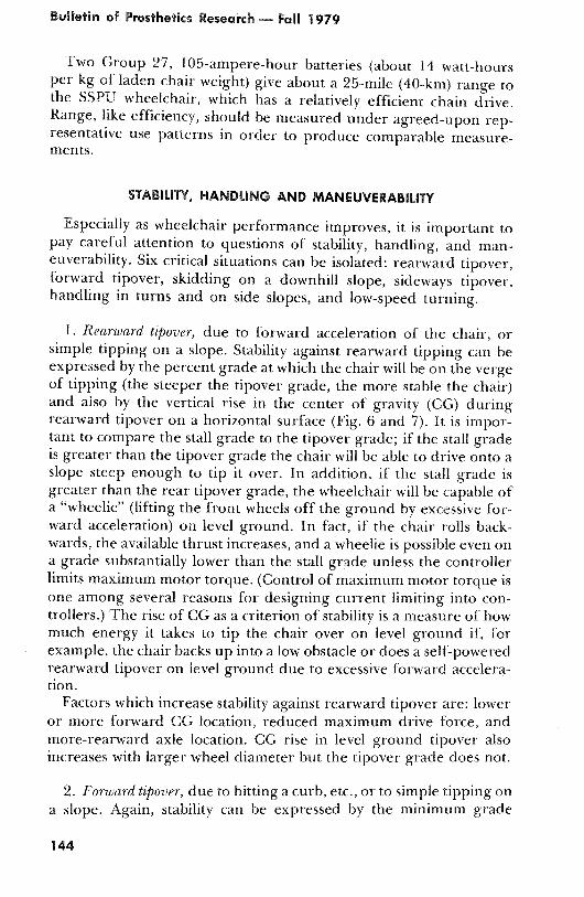
1. Rearward tipover, due to forward acceleration of the chair, orsimple tipping on a slope. Stability against rearward tipping can beexpressed by the percent grade at which the chair will be on the vergeof tipping (the steeper the tipover grade, the more stable the chair)and also by the vertical rise in the center of gravity (CG) duringrearward tipover on a horizontal surface (Fig . 6 and 7) . It is impor-tant to compare the stall grade to the tipover grade ; if the stall gradeis greater than the tipover grade the chair will be able to drive onto aslope steep enough to tip it over . In addition, if the stall grade isgreater than the rear tipover grade, the wheelchair will be capable ofa "wheelie" (lifting the front wheels off the ground by excessive for-ward acceleration) on level ground. In fact, if the chair rolls back-wards, the available thrust increases, and a wheelie is possible even ona grade substantially lower than the stall grade unless the controllerlimits maximum motor torque . (Control of maximum motor torque isone among several reasons for designing current limiting into con-trollers .) The rise of CG as a criterion of stability is a measure of howmuch energy it takes to tip the chair over on level ground if, forexample, the chair backs up into a low obstacle or does a self-poweredrearward tipover on level ground due to excessive forward accelera-tion.
Factors which increase stability against rearward tipover are: loweror more forward CG location, reduced maximum drive force, andmore-rearward axle location . CG rise in level ground tipover alsoincreases with larger wheel diameter but the tipover grade does not.
2. Forward tipover, due to hitting a curb, etc ., or to simple tipping ona slope. Again, stability can be expressed by the minimum grade
144

High Performance Wheelchairs
FIGURE 6 . — The rearward tipover grade is just steepenough to cause the wheelchair to be (statically) on theverge of tipping backwards.
which will cause forward tipping, or by the vertical rise in the centerof gravity during forward tip-over on level ground . (Fig . 8 .) Note thatwhile electric wheelchairs are generally harder to tip forwards thanbackwards, forward tipover is likely to be more dangerous than rear-ward tip-over since the wheelchair may land on its occupant.
Factors increasing stability against forward tipover are : lower ormore rearward CG location or a more forward front caster location.
3. Skidding on a downhill slope because of weight transfer to frontcaster wheels . Because the typical wheelchair configuration has nofront wheel brakes or steering, all control is lost when the rear wheelslose traction. For a given wheelchair, we can calculate the necessarycoefficient of friction between tires and ground to prevent skiddingon (for example) a 20 percent grade . The higher the required fric-tion, the more prone the chair is to skidding. (This is also a goodindex of the tendency of the chair to skid one or both rear wheelswhen applying reverse torque to slow down or steer the chair on levelground.) (Fig. 9 .)
Factors reducing the tendency to skid are : a lower or more rear-ward CG, or a more forward position of the front casters.
REARWARD TIPV
GRADE tars 9 RT

auuetan of rrosthetics Research ®— Fall 1979
FIGURE 7 .—Rearward tipover on level ground due to excessive forward acceleration.Center of gravity (CG) rise is a measure of the energy required to tip the chair back-wards to the point of no return . (Chair shown has 12-inch rear wheels .)
FORWARD TIPOVER
GRADE = tan OFT
FIGURE 8 . — The forward tipover grade is the gradewhich is just steep enough to cause the wheelchair to he(statically) on the verge of tipping forwards.
146

High Performance Wheelchairs
FIGURE 9 . — Skidding on a downhill slope is caused byweight transfer to the freewheeling front casters.
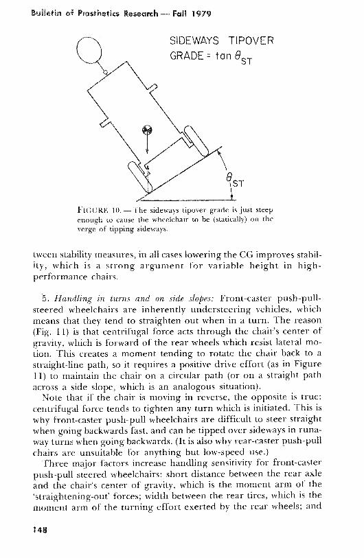
4 . Sideways tipover . Front-caster wheelchairs with normal push-pullsteering have an inherent safeguard against sideways tip-over : if apush-pull steered wheelchair with front casters is driven onto a sideslope extreme enough to risk tipping it over, the uphill drive wheelunweights completely and skids, and the chair simply points downhill.(See "Handling in turns and on side slopes", which follows .) Chairswith power steering do not have this safeguard, and need carefulattention to questions of lateral stability . But collisions, drivingcrosswise off a curb, or making a sharp turn while moving in reversecan tip any chair over sideways, and the tipover grade as shown inFigure 10 is a good index of lateral stability.
Sideways tipover stability is improved by lowered CG and increasedchair width.
Calculation of these indices of stability should take into account thestatic deflections of spring suspension so that some of the destabiliz-ing effect of the suspension is reflected in the stability measures . Notethat while fore-and-aft CG position is a matter of compromise be-
Bulletin of Prosthetics Research— Fall 1979
FIGURE 10 . —The sideways tipover grade is just steepenough to cause the wheelchair to be (statically) on theverge of tipping sideways.
tween stability measures, in all cases lowering the CG improves stabil-ity, which is a strong argument for variable height in high-performance chairs.
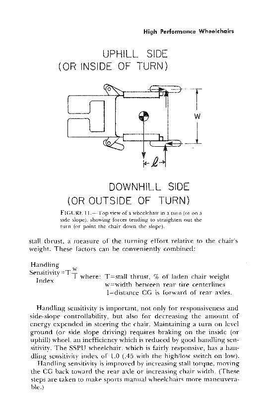
5 . Handling in turns and on side slopes : Front-caster push-pull-steered wheelchairs are inherently understeering vehicles, whichmeans that they tend to straighten out when in a turn . The reason(Fig . 11) is that centrifugal force acts through the chair's center ofgravity, which is forward of the rear wheels which resist lateral mo-tion. This creates a moment tending to rotate the chair back to astraight-line path, so it requires a positive drive effort (as in Figure11) to maintain the chair on a circular path (or on a straight pathacross a side slope, which is an analogous situation).
Note that if the chair is moving in reverse, the opposite is true:centrifugal force tends to tighten any turn which is initiated . This iswhy front-caster push-pull wheelchairs are difficult to steer straightwhen going backwards fast, and can be tipped over sideways in runa-way turns when going backwards . (It is also why rear-caster push-pullchairs are unsuitable for anything but low-speed use .)
Three major factors increase handling sensitivity for front-casterpush-pull steered wheelchairs : short distance between the rear axleand the chair's center of gravity, which is the moment arm of the`straightening-out ' forces; width between the rear tires, which is themoment arm of the turning effort exerted by the rear wheels ; and
SIDEWAYS TIPOVER
GRADE = tan 8ST
¶ST
148
High Performance Wheelchairs
UPHILL SIDE(OR INSIDE OF TURN)
DOWNHILL SIDE
(OR OUTSIDE OF TURN)FIGURE 11 .-Top view of a wheelchair in a turn (or on aside slope), showing forces tending to straighten out theturn (or point the chair down the slope).
stall thrust, a measure of the turning effort relative to the chair'sweight . These factors can be conveniently combined:
HandlingSensitivity=T 1 where
: T=stall thrust, % of laden chair weightIndex
w=width between rear tire centerlines1=distance CG is forward of rear axles.
Handling sensitivity is important, not only for responsiveness andside-slope controllability, but also for decreasing the amount ofenergy expended in steering the chair . Maintaining a turn on levelground (or side slope driving) requires braking on the inside (oruphill) wheel, an inefficiency which is reduced by good handling sen-sitivity. The SSPU wheelchair, which is fairly responsive, has a han-dling sensitivity index of 1 .0 ( .45 with the high/low switch on low).
Handling sensitivity is improved by increasing stall torque, movingthe CG back toward the rear axle or increasing chair width . (Thesesteps are taken to make sports manual wheelchairs more maneuvera-ble .)

Bulletin of Prosthetics Research ®- Fall 1979
6 . Low-speed turning resistance . When a wheelchair is turned at lowspeed, the casters have a significant frictional resistance to turningabout the caster pivot axis . This creates a lateral force on the casteraxis bearings which resists the intended turn . The turning resistanceis aggravated by (Fig . 12) : a long caster-axis-to-rear-axle wheelbase,which is the moment arm of the resisting force ; and weight on thefront casters, which increases the resisting force. Stall thrust andwheelchair width counteract turning resistance . An index of low-speed turning resistance is:
Caster drag leverage
T=stall thrust, % of ladenchair weight
w=width between rear tirecenterlines
The actual resistance of the caster to turning about the caster pivotaxis when the wheel is not rolling is the other major part of thelow-speed resistance to maneuvering . A caster turning friction coeffi-cient can be defined as the lateral force necessary to move the front of
FIGURE 12 . — Resistance to turning at low speeds is ag-gravated by the lateral resistance of the casters and therear-wheel-to-caster-pivot moment arm, and helped by thewheelchair width moment arm.
here : 1,=distance from rear axle tocaster pivot
C =% of laden chair weighton front casters
Tw
150

Hiah Performance Wheelchairs
the chair sideways (when the wheels are not rolling) divided by theweight carried by the casters . This can be measured directly by settingthe casters straight ahead, removing brakes and drives as necessary sothe rear wheels can turn freely, and measuring the peak force it takesto push the front of the chair sideways r/2 in. or so (pushing sidewayson the caster barrel) . The coefficient of friction between the tire andground is clearly crucial . One approach would be to use a dry,sidewalk-rough concrete surface for one measurement, and foranother put the casters on relatively frictionless turntables . Thiswould allow an assessment of the proportion of the total turningresistance in the caster bearings and that in the tire footprint . (This isalso relevant to the question of caster shimmy discussed later .)
The product of the caster drag leverage and the caster turningfriction coefficient gives a measure of total resistance to turning atslow speeds .
MOTORS °
The compactness, efficiency, lightness and low cost of thepermanent-magnet DC motor make it the prime candidate for wheel-chair° use, notwithstanding some interesting controller concepts whichinvolve other kinds of motors . Figure 13 shows the form of thecharacteristic curves of a permanent-magnet DC motor operating atfixed voltage . The conditions of operation represented by the curvescan be visualized as follows: batteries are connected across the motorterminals (which is about the same as pushing the joystick to theextreme of its travel) and a brake mounted on the motor shaft pro-vides variable output torque (which is about the same as putting thewheelchair on a slope of variable steepness) . The motor speed dropslinearly from its maximum at zero output torque to zero speed at stalltorque; from this speed-torque curve we can derive the curve of out-put power versus torque, which has a parabolic form reaching itsmaximum at half of stall torque . The motor's continuous-duty ratedpower is considerably less than the peak power, and while shortperiods of operation above rated power are permissible, extendedperiods will cause damage from overheating.
The motor draws current in direct proportion to the torque it pro-duces ; limiting current is an effective way of limiting torque . Themotor's efficiency curve drops at the extreme low-torque end due tobrush and bearing drag, but basically falls linearly with increasingtorque, reaching zero at stall torque . If the brush and bearing drag
e Reference 11 has a good discussion of permanent-magnet DC motors .

1500 —
6
2et.
p1000
0ww
500to
t a a10 20 30 40 50 60 70 80 90 100
TORQUE, N-LB1Ct0
• (•:t
10 20 30 40 50 60 70 80 90 100 110TORQUE, N-LB
80
60
40 • 2
20
are ignored, efficiency falls linearly from some maximum value (lessthan 100 percent) at zero torque to zero at stall torque . (Note : theefficiency curves shown in Figure 13 through 16 are based on man-ufacturers' data and should not be relied on for precision .)
If we choose a drive ratio and laden weight for the chair we cantranslate motor speed in revolutions-per-minute into wheelchair
I 1 1 a 1 1 1 I
10 20 30 40 50 60 70 80 90 100TORQUE, N-LB
FIGURE 13 . — DC permanent-magnet motor characteristics .
110
152
High Performance Wheelchairs
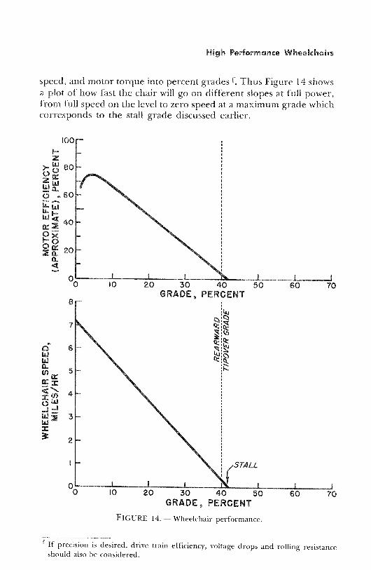
speed, and motor torque into percent grades I . Thus Figure 14 showsa plot of how fast the chair will go on different slopes at full power,from full speed on the level to zero speed at a maximum grade whichcorresponds to the stall grade discussed earlier.
0 11 I 1 1' 1 I0
10
20
30
40
50
60
70GRADE, PERCENT
FIGURE 14 . — Wheelchair performance.
f If precision is desired, drive train efficiency, voltage drops and rolling resistanceshould also be considered .
Bulletin of Prosthetics Research — Fall 1979
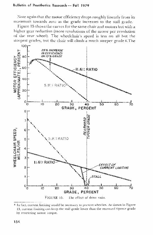
Note again that the motor efficiency drops roughly linearly from itsmaximum towards zero as the grade increases to the stall grade.
Figure 15 shows the curves for the same chair and motors but with ahigher gear reduction (more revolutions of the motor per revolutionof the rear wheel) . The wheelchair's speed is less on all but thesteepest grades, but the chair will climb a much steeper grade R .The
10025% INCREASE
Z /N EFFICIENCY>- ow 80 ON /5 % GRADE
g In fact, current limiting would be necessary to prevent wheelies . As shown in Figure15, current limiting can keep the stall grade lower than the rearward tipover gradeby restricting motor torque.
20
30
40GRADE, PERCENT
10
20
30
40
50
60
70
GRADE, PERCENTFIGURE 15 . --The effect of drive ratio.
154
High Performance Wheelchairs
efficiency curve slopes downwards more gently with increased grade,so on steep grades the motor efficiency is much higher than before.For example, on a 15 percent grade, efficiency is 25 percent higherthan with the lower gear reduction . If a variable-speed transmissionwere used to shift continuously between ratios, we would keep thegood level-ground speed of the first case and add the good hill-climbing ability of the second, along with substantially increasingmotor efficiency on steep grades . If the transmission is efficient, sim-ple, and inexpensive enough, this may be an excellent solution.
Another approach to the problem is to increase the size of themotors . As shown in Figure 16, this also increases the stall thrust andlessens the downward slope of the efficiency curve in much the sameway so that, again, motor efficiency on steep grades is increased . Thedifference is that the available power is greater, so speed on hills isenhanced relative to the multiple-ratio case . The cost is slightlyheavier, bulkier, and more expensive motors h .
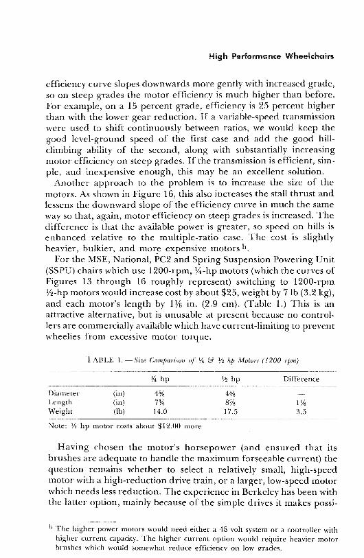
For the MSE, National, PC2 and Spring Suspension Powering Unit(SSPU) chairs which use 1200-rpm, ¾ -hp motors (which the curves ofFigures 13 through 16 roughly represent) switching to 1200-rpm1/2-hp motors would increase cost by about $25, weight by 7 lb (3 .2 kg),and each motor's length by 1 Vs in . (2 .9 cm). (Table 1 .) This is anattractive alternative, but is unusable at present because no control-lers are commercially available which have current-limiting to preventwheelies from excessive motor torque.
TABLE 1 . — Size Comparison of %a & 1/2 hp Motors (1200 rpm)
% hp ½ hp Difference
Diameter (in) 4% 4% —Length (in) 7 3/4 8% 1 i/sWeight (lb) 14 .0 17 .5 3 .5
Note : ½ hp motor costs about $12 .00 more
Having chosen the motor's horsepower (and ensured that itsbrushes are adequate to handle the maximum forseeable current) thequestion remains whether to select a relatively small, high-speedmotor with a high-reduction drive train, or a larger, low-speed motorwhich needs less reduction . The experience in Berkeley has been withthe latter option, mainly because of the simple drives it makes possi-
h The higher power motors would need either a 48 volt system or a controller withhigher current capacity . The higher current option would require heavier motorbrushes which would somewhat reduce efficiency on low grades.

tsuttetan at Prosthetics Research — Fall 1979
ble . Consider the effect of replacing the 1200-rpm %4-hp motors with3600 rpm motors also of %4 hp, and changing from a 5 .8 :1 drive ratioto 17 .4 :1, giving about the same speed/grade characteristics . Themajor benefit is that each motor is .81 in (2 .1 cm) shorter, and a pairof motors is 5 lb (2 .3 kg) lighter and costs about $28 less i .(See table 2 .)Whether these weight and space savings are worthwhile depends on a
Alternatively, 3600 rpm motors of i/2 hp are about the same size and cost as the1200-rpm ¼ -hp motors, and offer greater capacity and efficiency.
2/ % INCREASEIN EFFICIENCYON /5% GRADE
0_ t t t30
40
8
GRADE, PERCENT
21/4 HP MOTORS
R iO
1
1 t o%00
10
20
30
40
50
GRADE, PERCENTFIGURE 16 . — The effect of motor size.
156

High Performance Wheelchairs
consideration of what penalties are paid in obtaining the higher re-duction drive train necessary for the higher speed motors.
TABLE 2 . —Size Comparison of 1200 and 3600 r-pm ¼ hp Motors
1.200 rpm 3600 rpm Difference
Diameter (in) 4 5/s 4% —Length (in) 7% 6 15/1s 13/16
Weight (lb) 14 .0 11 .5 2 .5
Note : 3600 rpm motor costs about $14 .00 less but requires about three times as high agear ratio
Note : 3600 rpm 1/2 hp motor is same size, weight and cost as 1200 rpm'/ hp motor.
DRIVE TRAIN
Table 3 gives some performance and cost characteristics of severalof the many possible drive train types . (Among those omitted areplanetary, harmonic, Orbi-Drivel, and variable-speed transmissions .)The intent of the table is to give a rough description of some of theavailable options, and all of the numbers presented are approximate.
Drive train costs are presented in the table as a percentage of themost expensive type . The cost difference between the more and lessexpensive systems is large for low volume production, but decreasesfor greater quantities . Furthermore (as discussed later) initial costsavings may be overshadowed by maintenance costs, which means thatthe more expensive systems may in fact be economical choices . En-closed gearboxes can provide excellent durability and low-maintenance operation, and should be seriously considered for anychair likely to be produced in quantity.
The drive train should be designed in conjunction with the motors,wheel size, and chair layout, in order that the cost and efficiency ofthe overall system can be optimized . High peak drive torques oftenoccur in normal wheelchair use, which must be reflected in adequatestrength of drive components.
SPRING SUSPENSION
A number of wheelchairs have spring suspension, and trials of theMED, PC2 and SSPU wheelchairs indicate that this is a very worth-while feature, especially for a fast chair which is used outdoors . Ride
j Available from Compudrive Corp ., North Billerica, Mass.

TABLE 3 . —Characteristics of Drive Trains
FrictionontoTire
Frictiononto Separate
Surface
WormGearboxwith Belt
EnclosedWorm
Gearbox
EnclosedSpur
Gearbox
EnclosedHelicalGearbox
Single StageChain
(Silent Chain)Single StagejTiming Belt
Efficiency 65-80% 70-85% 60-80% 65-90% 90-97% 90-97% 80-95% 75-90%
Noise Excellent Excellent Good/exc . Good/Exc . Fair GoodFair
(Good) Good
Maintenance(if well
designed)
Fair-adjust,replace
tiresadjust?
Good-adjust,replace
beltsExcellent Excellent Excellent
Good-adjust,clean, oil,
replace chains
Good-adjust,replace
belts
Wet weatherperformance
can slip can slip?belt can
slipExcellent Excellent Excellent Excellent Excellent
Flat tiredrivability
can't be a
driven Drivable Drivable Drivable Drivable Drivable Drivable Drivable
Cost(relative to
Worm)40 70 100 70 80 ( 80 ) 40
Compactness Excellent Fair Fair Fair/good Fair/Exc . Fair/Exc . Poor
Durability(if well
designed)
hard on atires Good Excellent Excellent Excellent Good Good
MaximumReductionper stage
20 :1 10 :1 200 :1 70 :1 8 :1 8 :1 7 :1 6 :1
a The rear tires of VISE wheelchairs are often filled with BykFil, a rubber compound . This eliminates the flat-tire drivability problem, as well asincreasing drive efficiency and tire life.

High Performance Wheelchairs
comfort is much improved, driving fatigue is reduced, and good ac-commodation to rough terrain can be assured. The PC2 and SSPUwheelchairs have independent rear swing-arm suspension, with ten-sion springs and motorcycle steering shock absorbers. The MED chairhas front and rear swing-arms and four-wheel independent suspen-sion (utilizing rubber torsion springs) which appears to give an excel-lent ride . The Newton wheelchair also has rubber torsion springs forits independent rear swing-arm suspension, but the spring rate israther high for maximum confort.
How soft should the ride be? Spring rate is a good measure of ridefirmness, though for comparisons between chairs it is best to considerthe weight on the wheel and express the firmness in terms of thenatural frequency . k The SSPU rear suspension has a spring rate of 57lb/in (98 N/cm) at each wheel, which with 91 lb on each rear wheelcorresponds to an undamped natural frequency of 2 .5 cycles/second.The MED chair has a spring rate of 28 lb/in (49 N/cm) for each rearwheel, which with about 100 lb (45 kg) on each rear wheel gives anatural frequency of about 1 .6 cycles/second . Five problems may arisewhen the ride is softened much beyond these values:
1. Suspension travel must be increased to avoid bottoming out withthe softer springs, and long travel may be impractical because, forexample, the footrests strike the ground . A good measure of theadequacy of suspension travel is the maximum height from which thechair can be dropped without bottoming out . For the SSPU wheel-chair this is 2 .5 in (6 cm) which means that the chair can be driven offa 2.5 in curb without bottoming out . This seems adequate to preventbottoming in most situations.
2. Static lateral, rearward, and forward tipover stability may becompromised by center of gravity shifting due to large suspensiontravels . Stability measures should reflect this fact (see discussion ofstability above).
3. Because of its high center of gravity, a wheelchair has a largemoment of inertia in pitch (and in roll) . Care must be taken thatdeflections, especially in the pitch mode of vibration, do not becomeexcessive.
4. Excessive rear-end squat and front-end dive may result fromacceleration and braking, respectively. A similar problem exists withautomobiles, where the front end dropping down during brakingmay tilt the seats forward enough to aggravate the tendency to slideforward . With a rear swing arm suspension it is possible to locate the
k Simplifying the problem to a one degree of freedom spring-mass system,
f = 2~ V/rn where f is the undamped bounce frequency, k is the spring rate atthe wheel, and m is the mass carried by the wheel .
Bulletin of Prosthetics Research — Fall 1979
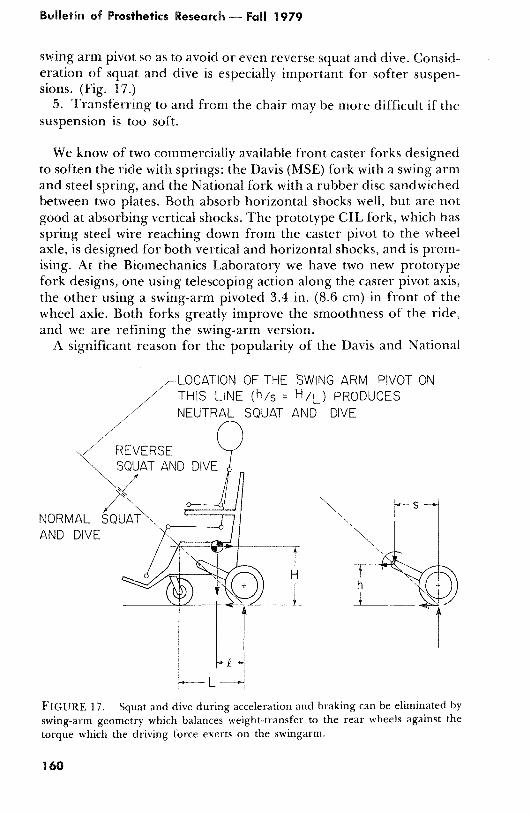
swing arm pivot so as to avoid or even reverse squat and dive . Consid-eration of squat and dive is especially important for softer suspen-sions . (Fig . 17.)
5. Transferring to and from the chair may be more difficult if thesuspension is too soft.
We know of two commercially available front caster forks designedto soften the ride with springs : the Davis (MSE) fork with a swing armand steel spring, and the National fork with a rubber disc sandwichedbetween two plates. Both absorb horizontal shocks well, but are notgood at absorbing vertical shocks . The prototype GIL fork, which hasspring steel wire reaching down from the caster pivot to the wheelaxle, is designed for both vertical and horizontal shocks, and is prom-ising. At the Biomechanics Laboratory we have two new prototypefork designs, one using telescoping action along the caster pivot axis,the other using a swing-arm pivoted 3 .4 in . (8 .6 cm) in front of thewheel axle. Both forks greatly improve the smoothness of the ride,and we are refining the swing-arm version.
A significant reason for the popularity of the Davis and National
LOCATION OF THE SWING ARM PIVOT ONTHIS LINE (h/s = H/L ) PRODUCESNEUTRAL SQUAT AND DIVE
FIGURE 17 .-Squat and dive during acceleration and braking can be eliminated byswing-arm geometry which balances weight-transfer to the rear wheels against thetorque which the driving force exerts on the swingarm.
160
High Performance Wheelchairs
forks is their ruggedness compared to conventional forks, which arenot strong enough for use on wheelchairs which go over 3 mi/hr.
The question arises whether the spring suspension effect can beobtained by using large soft tires instead of the relatively expensivemechanical means discussed above . Reducing tire pressures to lowerthe spring rates to acceptable levels courts two problems : lower tirepressures increase rolling resistance (and hence power consumption),and bigger tire footprints (though desirable on soft ground) make thechair harder to turn at low speed . It would be worth looking intowhether proper tire design might mitigate these problems.
WHEEL SIZE
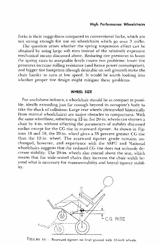
For usefulness indoors, a wheelchair should be as compact as possi-ble, ideally extending just far enough beyond its occupant's body totake the shock of collisions . Large rear wheels (descended historicallyfrom manual wheelchairs) are major obstacles to compactness . Withthe same wheelbase, substituting 12-in . for 20-in. wheels can shorten achair by 4-in. without affecting the parameters of stability discussedearlier except for the CG rise in rearward tipover . As shown in Fig-ures 18 and 19, the 20-in . wheel gives a 35 percent greater CG risethan the 12-in . wheel . The rearward tipover grade remains un-changed, however, and experience with the SSPU and Nationalwheelchairs suggests that the reduced CG rise does not seriously de-crease stability . The 20-in . wheels also extend above the seat, whichmeans that for wide-seated chairs they increase the chair width be-yond what is necessary for maneuverability and lateral tipover stabil-ity .
FIGURE 18 . — Rearward tipover on level ground with 12-inch wheels .

Bulletin of Prosthetics Research — Fall 1979
C.G. RISE 35%
GREATER THAN
WITH 12 " WHEELS
FIGURE 19 . — Rearward tipover on level ground with 20-inch wheels.
Beside the compactness advantages, a 12-in . wheel requires only 60percent of the drive reduction of a 20-in . wheel . This means that witha 1200 rpm motor a single stage chain or spur gear reduction ispossible, which can be a great simplification . Furthermore, since themajor loads on the wheel bearings are from the moment caused byside loading the wheel, the 12-in . wheel has much lower bearing loadsthan a 20-in . wheel.
Concern has been expressed that the 12-in . wheels will have prob-lems traversing bumps. This does not appear to be a problem,perhaps because the 8-in . casters are the limiting factor in either case;the SSPU wheelchair can climb up a 31-in . curb, which is adequatefor many purposes . The 12-in . wheels will have a somewhat higherrolling resistance, but this will probably be offset by the increasedefficiency of the lower ratio drive.
For a given tread material and thickness, smaller diameter tires canbe expected to have a shorter tire life, since they have a smaller cir-cumference on which to carry rubber . While the 20-in . tires are avail-able in a wide variety of profiles and rubber compounds, this will notbe true of smaller sizes until they become more widely used . The
16-in. x 1M-in . tires used on the PRAHN I and CIL chairs use readilyavailable black rubber Schwinn Sting-Ray bicycle tires, which can bemade in grey rubber if demand is sufficient . The National and Scottchairs both use 12-in . go-cart tires, which have good availability andruggedness for both tires and wheels, but are a minimum of 3½-in.wide and hence rather space-consuming . We favor a 12½-in. x 2%4-in.tire, a size used on wheelchairs in Europe, which is available in whiterubber as a relatively lightweight scooter tire in the U .S . and also as a
heavier duty tire in black and grey rubber in Germany.
162
High Performance Wheelchairs
BRAKES AND OTHER SAFETY EQUIPMENT
A high-performance wheelchair must have a reliable braking sys-tem. The usual method of using resistance braking across the motor isvery inexpensive and reasonably effective, but though it providessome degree of protection against electronic failures it is not in itselfan adequate fail-safe backup system . Resistance-braking torque variesdirectly with the speed of the wheelchair, which leads to sharp brak-ing at high speed, and little braking at low speed . This introducessome jerkiness in the controls at high speeds, and also means thatauxiliary parking brakes are required.
The Compass, National, Permobil, SSPU and PC2 wheelclhave independent brakes, which we feel is a necessity with high-performance wheelchairs . The manual brakes on the Col
(outdoor chair with manual steering and brakes) are effeedy, , fullyproportional brakes, though they require a positive effort to s
thechair.
The National wheelchair has an interesting braking system wlapplies brakes each time the joystick moves through neutral, pcing the double function of "dead man's" brakes (applied when (joystick is released) and slowing down the motors when switchingbetween forward and reverse, which prevents current surges danger-ous to the controller . The spring-loaded brakes are activated whenpower to an electromagnet is interrupted . The application of thebrakes while passing through neutral makes the control response veryjerky, however, and there is no manual brake disconnect to allow thechair to be pushed with dead batteries.
The Swedish Permobil chair has servoactivated brakes for whichthe interruption of power applies the brakes . This sounds like anideal, if bulky and expensive, system, since it combines proportionalbraking with fail-safe response.
The brakes on the SSPU and PC2 chairs, like those on the Nationalchair, are fixed-torque brakes which are activated by the interruptionof power to a solenoid . A pivoted, lightly spring-loaded paddle on topof the joystick box (other locations are possible, even the joystickitself) closes a switch which allows the chair to be driven when thepaddle is depressed by the hand holding the joystick. Sufficient over-travel of the paddle prevents small movements of the hand fromapplying the brakes . Removing the hand from the paddle activatesthe brakes . Brake torque is adjustable and brakes can be disconnectedfor manual pushing of the chair . Disadvantages are that jamming ofthe lightly sprung paddle could prevent activation of the brakes, andthat the dog-type brake now being used can accidentally be left en-

Bulletin of Prosthetics Research ® Fail 1979
gaged while the chair is driven, which can overheat the brakes.All of the systems just described function as parking and transfer
brakes.Features of a good braking system are:1. Application of brakes occurs upon interruption of power to
brakes.2. Brakes are controlled by a separate switch, not relying on the
controller logic (especially the neutral joystick position detectioncircuitry).
3. The switch which sets the brakes also interrupts power to themotors . This is necessary because if braking torque is set to ap-propriate levels for smooth stopping, the motor torque is suffi-cient to overcome the brakes.
4. The brakes should have a manual disconnect to allow manualpushing of the chair.
5. Ideally, location of the brake switch should be such that removalof control effort activates the brakes . The switch should be care-fully designed so that it is easily kept in the driving position.
Reflectors, lights, and horns are also safety equipment now appear-ing on wheelchairs . Their wider use should be encouraged by man-ufacturers offering them as standard options . Seatbelts and shoulderharnesses are also increasingly important to safety as wheelchair per-formance improves .
CASTER SHIMMY
There is an extensive literature on caster shimmy in aircraft appli-cations which deserves some attention (12,13) . Some general consid-erations are:
1. The rotational inertia of the fork and wheel about the casterpivot axis should be kept as low as possible . (This must be done withdue regard to strength, of course.) The wheel and tire especially mustbe kept light.
2. Looseness in the pivot or axle bearings should be minimized.3. Damping is required, either at the caster pivot or from the rota-
tional friction of the tire footprint on the ground . Viscous damping(with resistance proportional to rotational velocity) is ideal, becausethe increase in resistance to desired caster turning is minimal . Inpractice dry friction damping is much easier to obtain, but it decreasesslow speed maneuverability . The object is to have sufficient dampingto inhibit shimmy at the highest speeds expected ; for any amount ofdamping, a sufficiently high speed will generate shimmy.
The design of a compact, leakproof, reliable caster axis damper
164
High Performance Wheelchairs
permitting 360 deg rotation is possible and desirable — but so farelusive . Dry-friction damping can be obtained either by a large tirefootprint (which invites caster shimmy on slippery surfaces), or byfriction in the caster pivot . A method used in the PRAHN I and PC2wheelchairs is to use Rulon bushings for the caster pivot, along with a3A-in . dia fork stem to increase turning drag . E&J has a nylon bushingto replace the top caster bearing, which has a similar effect . We hadbeen satisfied with this arrangement until recently, when calculationsindicated that the turning drag is unnecessarily high ; Ralf Hotchkissof the Center for Concerned Engineering, Washington, D .C., pointedout that the configuration involves increased turning drag (without acorresponding increase in damping) because the side load on thewheel from turning puts an increased moment on the bushings . Apure thrust washer arrangement does not have this problem, thoughit is not clear whether it should be at the top caster bearing andspring-loaded for drag, or on the bottom using the weight on thecaster for drag . The latter solution is simpler, but may run into prob-lems with coupling between the shimmy and vertical motion, whichcould reduce (or increase) the damping just when it is most critical.Thorough study of this problem would be useful.
BATTERIES'
Batteries designed for starting automobiles have a short life whenused in wheelchairs, and batteries designed for deep cycling areslowly becoming more available in a full range of sizes . Still, batterylife even for deep cycling batteries is typically short, perhaps 3–9months for a fairly active person . This is 90 to 270 charge/dischargecycles, which is considerably less than the 500-cycle life expected fromsuch batteries . (Table 4) Since battery replacement costs are substan-tial, some research attention is needed to establish what the actual lifeis under realistic conditions, and what can be done to improve it . Inparticular, while it is clear that excess battery capacity on a chairmakes batteries last longer because they are cycled less deeply, thisrelation needs to be quantified so that rational decisions can be madeabout how much battery capacity a chair should have.
Battery charging also affects battery life, and information on theeffect of different charging cycles is needed for the design of im-
Given the economics of the wheelchair market, the internal combustion engine is theonly serious alternative energy source to batteries, and due to the necessity of indooroperation, it would have to be used in an electric/IC hybrid system . Such systemsseem to be too bulky and costly for general use . The University of Virginia REC hasdesigned such a system (14) .

Bulletin at Prosthetics Research—Fall 1979
TABLE 4 . —Characteristic s of Engineering Batteries (15)
State-of-the-artPb/acid
ImprovedPb/acid(goals)
ImprovedNi/Z.n(goals)
ImprovedNi/Fe(goals)
Specific energy, 35 50 90 60W^h/kg a
Volumetric energy 60 90 150 110density, W-h/l
Energy efficiency, % 65 65 65 60
Cycle life 500 1000 750 2000
Cost, 45 45 60 75a Assumes discharge at the 3-h rate.
proved battery chargers . Battery chargers also need some design at-tention with a view to reducing their bulk, so that they can be carriedon a chair. Some work has been done on a charger concept at theOntario Crippled Children's Center involving a frequency multiplierto reduce the size of the transformer ; this seems like a promisingapproach which should be pursued. There is also a need for a com-pact but rugged battery terminal connector with an integral plasticcover, to prevent objects from shorting the battery with resultantarcing, which can cause an explosion of the hydrogen gas which maybe present . Most wheelchairs have inadequate battery covers, as wellas non-weather-resistant wiring in general.
As to improving the batteries themselves, a clear short-term need isto reduce the maintenance required, since many battery failures inactual use are attributable to poor maintenance . Sealed batteries nowbeing used in cars would be excellent for wheelchairs if they could beredesigned for deep cycling capacity . Improvement both in batterysealing and in charging methods could both reduce the generation ofhydrogen gas, which as mentioned above can cause dangerous explo-sions.
There is considerable new research taking place in batteries with aview to improving performance for electric vehicles . Increasedenergy density and life are hoped for in the next 5 years, though howmuch and at what increase in cost is uncertain . A study conducted atthe Lawrence Livermore Laboratories (15) describes present and ex-pected battery performance, but with the caution that predictions offuture battery performance have traditionally been over-optimistic.(See Table 4 .) The report estimates that the probability of any of thesebatteries reaching all of their performance goals within 5 years is lessthan 50 percent.
What would be the effect of higher energy-density batteries for
166

High Performance Wheelchairs
wheelchairs? Lightweight folding wheelchairs would increase dramat-ically in range, which would both widen their appeal and increase thepressure to upgrade their durability and performance . High-performance nonfolding chairs (which now allocate 25 percent ofladen weight to batteries) would clearly improve in performance witha lighter battery pack, though attention will have to be paid to stabilitybecause the heavy batteries currently used help lower the center ofgravity . The possibility of lighter batteries may increase the desirabil-ity of variable-height chairs.
We should take a lesson from the fact that, at present, sealed bat-teries are available for cars but not wheelchairs . The wheelchair in-dustry is small, and it will take energetic action to ensure that newbattery technology gets to us.
CONTROLLERS
Higher performance wheelchairs demand higher current capacitiesfrom their controllers, and there is still a need for a safe, reliable,rugged, and inexpensive controller . There are many special featureswhich are desirable in a controller, but with all aspects of wheelchairs,reliability and ruggedness are the basic requirements . Some possiblefeatures are:
1. Current Limiting, to protect the power transistors and also toprevent excess motor torque (for example, when deliberately pushingthe joystick forward while moving backwards) which can tip the chairover backwards . High priority.
2. Soft Start circuitry that applies power gradually (even if joystickmovements are sudden) to inhibit sudden acceleration without reduc-ing hill climbing capacity (as happens with straight current limiting).This is effected by time-averaging the joystick input signal and isuseful for people with motion disorders . (Reference 16 describes atime-averaging system .)
3. Speed Limiting in Reverse, to prevent rearward tip-over due tocollisions while backing up . Low speed torque in reverse should notbe reduced, however.
4. Regenerative Braking, to feed braking energy back into the bat-teries . Electric cars gain 15 percent or so in range from regenerativebraking, and wheelchairs might expect somewhat greater benefitssince they use braking to steer.
5. Push-Pull Steering with Feedback, which would use feedback of themotor speed to obtain more precise steering control . Such a systemwould make the joystick function as a turning radius selector (like acar's steering wheel) rather than as a steering torque selector (like a
Bulletin of Prosthetics Research — Fall 1979
boat's rudder or a standard wheelchair) . This could increase drivingcontrol and smoothness, but would not eliminate one of the maindisadvantages of push-pull steering at outdoor speeds : the unneces-sary dissipation of energy because of the application of braking tor-que to steer the chair.
6. Power Steering, which does eliminate much of the inefficiency ofpush-pull steering at some cost in complexity . It is doubtful, however,whether a power-steered chair can ever be as maneuverable indoorsas a chair with push-pull steering, which suggests the use of a powersteering unit in conjunction with push-pull steering. In this concept,the power steering servo, which acts on one caster, can disengageitself at one extreme of its travel, allowing operation in the push-pullmode . When driving outdoors, the power steering is engaged (withthe chair stopped) and the controller operates in a second mode usingthe same drive motor controls, but with control of the servo for steer-ing. A disadvantage of power steering is that a power-steered chair,unlike a push-pull steered chair, can be tipped over fairly easily dur-ing a sharp turn on level ground . This requires either extra cautionon the part of the driver or safety interlocks to prevent turning toorapidly at high speeds.
7. Solid State Circuitry, which eliminates the noisy and unreliablerelays. A four-transistor bridge across each motor, with two transis-tors switched on at a time, allows on-off pulsing of the desired polar-ity . It is also possible to use only two transistors, and use one batteryfor forward, one for reverse (using the batteries the other way aroundfor the other motor to assure even use) though this means using onlya 12-volt system, with its lower efficiency and higher current re-quirements . (The Biomechanics Lab. is working on the design of asolid state controller, which we hope will provide smooth, somewhatregenerative braking .)
8. Motor and Brake Temperature Sensing, automatic circuitry or warn-ing lights to guard against motor or brake damage from overheating.This can be a fairly simple thermal cutout device, or better, a morecomplicated system which reduces current to the motor if the motoroverheats.
9. Adjustable Maximum Speed and Torque, to limit the wheelchair ' sperformance to suit individual requirements (or for high seat posi-tions of variable height wheelchairs) . This should be in addition to thenormal high/low speed switch.
10. Downhill Speed Limiting, a feature commonly incorporated incontrollers by placing a diode across the output power transistor.(The diode also protects the transistor against reverse voltage .) Whenthe chair exceeds its level-ground top speed, the motors generate
168

High Performance Wheelchairs
voltage above the battery voltage and current flows through the di-ode, charging the batteries and slowing down the chair.
11 . Higher-Voltage Operation . Especially if wheelchair performancecontinues to improve, 36- or 48-volt systems would be very attractivein efficiency and current levels compatible with inexpensive transis-tors .
VARIABLE HEIGHT
Variable height is a feature which can add considerable complexityto a wheelchair, but which has definite advantages . As discussed ear-lier, every measure of stability is improved by lowering the chair'scenter of gravity, and variable-height chairs are indeed much moreagreeable to drive outdoors with the seat low . A wheelchair whose seatlowers can be used for driving a van without lowering the floor orraising the roof, and that may save enough money in modifying thevan to more than pay for the variable-height feature . Raising the seatabove normal height is advantageous for access to counter tops andhigh objects, and also for conversing with standing people morenearly at eye level . The PC2 wheelchair automatically limitsmaximum wheelchair performance as the chair rises to the high posi-tion, to ensure adequate tipover stability.
FOLDABILITY
Especially for people who travel with the assistance of others in anautomobile, it can be very useful to have a compact, lightweight elec-tric wheelchair which can be readily folded and placed in a car's backseat or trunk . Many wheelchairs used in independent living situationsare never folded, however, and in any case, an indoor/outdoor wheel-chair weighing 200 lb (91 kg)--including 85 lb (39 kg) of batteries— .-isnot made much easier to handle by folding . Non-folding wheelchairscan have great advantages in strength as well as increased space forbatteries, motors and accessories.
A heavy, non-folding chair has different strength/weight trade-offsthan the lightweight folding electric . While unnecessary weight is tobe avoided, a few pounds of additional structural weight is not nearlyas important as it is with a chair that is routinely lifted by hand.High-performance chairs can and should be designed to withstand allforseeable use without structural failure.
RECLINERS
So many people require a recliner that the feature should probablybe an option on all but the simplest chairs . Recliners should he care-

Bulletin at Prosthetics Research -- Fall 1979
fully designed to obtain proper recline kinematics to avoid slidingand/or high shear forces due to the anatomical hip pivot not coincid-ing with the backrest pivot (17) . Proper kinematics can be obtained inone of two simple ways, by sliding the seat backward a few inchesduring recline (as on the Falcon, Rugg Chair and E&J IndependenceRecliner) or by sliding the backrest downward . Of these two, slidingthe backrest downward has the advantage of keeping the center ofgravity of the chair as far forward as possible, which can be helpfulwith a chair which has rearward tipover stability problems with thebackrest reclined . The sliding action of the backrest can be obtainedwith a freely sliding counterbalanced backrest, though such a backrestcan shift into the wrong position on the user's back, which can be areal annoyance . A much better solution is to constrain the backrestmotion, which can be done by one of a number of fairly simple link-ages or cable-and-pulley systems.
A second problem of recliners is keeping the feet on the footrestduring reclining . The problem here is that a person 's body rollsbackwards on the buttocks a few inches during reclining ; this movesthe knee backwards along the seat and pulls the feet off the footrest(if the legs are properly straightened out) . In the usual arrangementwhere the footrests rise in coupled motion with the reclining backrest,this problem is solved simply by offsetting the footrest pivot to a pointbehind and below the knee position . If properly done, this causes thefootrest to shift backwards the correct amount . On chairs where foot-rest motion is also possible independent of the recline action, thefootrest pivot must be kept at the knee to ensure proper footrestaction, so the simple solution described above will not work . Oneanswer is to slide the seat forward during recline just enough to keepthe knee aligned with the footrest pivot.
A third problem of recliners concerns the motion of the armrests,which should move to support the arms and keep the joystick box (if itis armrest-mounted) within easy sight and reach of the person in thechair . A method used on the PRAHN I and PC2 wheelchairs, and alsoon the E&j Independence Recliner, is to use an armrest pivoted fromthe non-sliding part of the backrest, with a link down to the seat . Thisconfiguration permits design so that the armrests follow the arm withno sliding or hunching up, and the front of the armrest tips upenough so the joystick box can be easily seen, but not so much that thearm is in danger of falling off. Collapsing the link to the seat alsoallows the armrest to fold away neatly for lateral transfer . The link tothe seat can be above the backrest/armrest pivot, which makes it acompression link, as on the PC2 . Good motion can also be obtainedwith an armrest pivot on the seat with a control link to the backrest.
170

High Performance Wheelchairs
COST-EFFECTIVE DESIGN FOR THE LIFE OF THE CHAIR
Wheelchair breakdowns are expensive, not only in inconvenienceand hazard to the user, but also in terms of repair costs . This shouldbe reflected in a design approach based on costs analyses of the entirelife of the chair, including maintenance costs and the cost of repairingbreakdowns (ideally with a cost allowance for inconvenience andhazard) weighted by the probability of the breakdown's occurrence.
At the risk of belaboring a point that has been made before, theselection of bearings is a good example of how considering costs overthe chair's lifetime changes important design decisions . The bearingarrangement that is still most common uses unsealed bearings in anarrangement which requires careful adjustment of preload (and al-lows destruction of the bearings by overly tight or loose preloading).Assuming a 5-year chair life, we can make an admittedly very roughcomparison with the cost of higher capacity sealed bearings in a con-figuration requiring no preload.
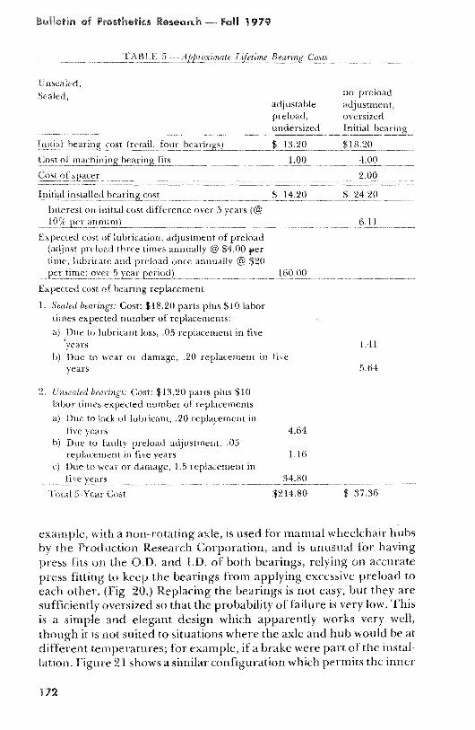
Table 5 compares the initial and lifetime cost for the two cases,based on estimates of retail prices . Note three things in that table:first, most strikingly, systems requiring regular maintenance are ex-pensive . (The $160 .00 5-year cost was built up from the manufac-turer's suggested maintenance schedule and shop time allocations forthe job, using a shop rate of $20 .00/hr) . Second, the cost of repairingthe bearing failures in the field is far greater than the cost of action atthe factory to prevent the failures (or make them much less likely).Third, no allowance is made for the cost of inconvenience and hazardto the user, a usual enough omission which leaves the true cost ofunreliability greatly understated.
Other aspects of wheelchair design have a similar tradeoff betweeninitial and lifetime costs . A chain or belt drive will probably have aconsiderably lower initial cost than an enclosed gearbox, but mayrequire enough additional maintenance and repair to be substantiallymore expensive in the long run . Undersized electric motors, drivetrain, structural or electronic components may also produce savings ininitial cost or weight, while increasing the total lifetime cost of the chair.
The redesign of wheelchairs for improved performance and heavieruse should be guided by the notion that reliability, durability andmaintenance-free operation are not luxuries, but necessary attributesof a safe, economical wheelchair.
BEARINGS
Three examples of sealed bearings used in configurations requiringno preload adjustment are found in Figures 20 through 22 . The first
Bulletiis of Prosthetics Research * Fall 1979
TABI..,E 5 --ter pi
Lijetint,
Rt ....
Unsealed,Sealed, no preload
adjustablepreload,undersized
adjustment,oversizedInitial bearingnnnn
n -Initial 11,
, t im cost
retatl
four bearings) $
13 .20-n nn .n..-.nnnn.nn nn.nn- -,a. n
$18 .20
Cos!:
t
hining bearing fits 1 00 4 .00
Cost (if sit :it
1 2 .00..nn.n..nnnnn
tlrch ta l tit
tailed bearing cost $14220 $tt 24 .20
Inti rest ou initial cost difference over 5 years (@10% per au uurn)_ _2
2_2 2 _i .e . _2_2_2_ _2_ 2 6 .1122 2_2
2rrr
Expected cost of lubrication, adjustment of preload(adjust pry Itta three times annually @ $4 .00 ipertime; labia vt and preload once annually @ $20per tin2 ,t 5 year period)
160ki0itt0 i
_
ttt
Expected cost of bearing replacement
1 . Sealed bearings : Cost : $18 .20 parts plus $10 labortimes expected number of replacements:
a) Due to lubricant loss, .05 replacement in five'years
1 .41b) Due to wear or damage, ,20 replacement in five
years
5 .64
2 .
,, trigs : Cost : $13 .20 parts plus $10labor times expected number of replacements
a) Due to lack of lubricant, .20 replacement infive years
4.64b) Due to faulty preload adjustment, .05
replacement in five years
1 .160 Due to weal or damage, 1 .5 replacement in
five years
34.80
Total 5-Year Cost
$214 .80
$ 37 .36
example, with a non- rotating axle, is used for manual wheelchair hubsby the Production Research Corporation, and is unusual for havingpress fits on the O.D. and I .D . of both bearings, relying on accuratepress fitting to keep the bearings from applying excessive preload toeach other . (Fig . 20.) Replacing the bearings is not easy, but they aresufficiently oversized so that the probability of failure is very low . Thisis a simple and elegant design which apparently works very well,though it is not suited to situations where the axle and hub would be atdifferent temperatures ; for example, if a brake were part of the instal-lation . Figure 21 shows a similar configuration which permits the inner
1 72

High Performance Wheelchairs
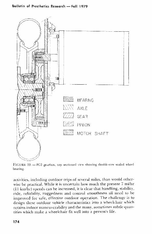
race of one bearing to float axially to permit take-up of thermal expan-sion differences. The third example, with a rotating axle, is thedouble-row sealed bearing used on the PC2 wheelchair, a simple andcompact arrangement made possible by the small (12-in .) rear wheeldiameter. The bearing cost is rather high at $15 .00 (small quantitywholesale price) but the bearing should outlast the chair . (Fig . 22.)
CONCLUSION
The high performance indoor/outdoor wheelchair is emerging as animportant mobility option which offers good outdoor performancewithout sacrificing usefulness indoors . The combination of indoor andoutdoor capability in a single vehicle can permit a much wider range of
lIII Al
110111
FIGURE 20 .—Bearing configuration used in ProductionResearch Corporation's manual wheelchair hubs, with pressfits on inner and outer races of both bearings.
w
M
Ul•lll
ll • Ii~W
i'•l l
li'illlafeS
w
FIGURE 21 . — Bearing configuration with provision foraxial bearing float in case of thermal gradients, with pressfits on both outer races, one inner race clamped against asnap ring, the other inner race a sliding fit .
Bulletin of Prosthetics Research — Fall 1979
AXLE
GEAR
PINION
MOTOR SHAFT
FIGURE 22 . — PC2 gearbox, top sectioned view showing double-row sealed wheelhearing.
activities, including outdoor trips of several miles, than would other-wise be practical . While it is uncertain how much the present 7 mi/hr(11 km/hr) speeds can be increased, it is clear that handling, stability,ride, reliability, ruggedness and control smoothness all need to beimproved for safe, effective outdoor operation . The challenge is todesign these outdoor vehicle characteristics into a wheelchair whichretains indoor maneuverability and the many, sometimes subtle quan-tities which make a wheelchair fit well into a person's life.
174
High Performance Wheelchairs
REFERENCES
1. Lipskin, Ronald : Trends in Nonlicensed Mobility Aids . Bull. Prosth . Res ., BPR
10-22, Fall 1974, 41-52.2. VAPC Research Report : VAPC Indoor-Outdoor Wheelchair . Bull . Prosth . Res .,
BPR 10-23, Spring 1975, 235-236.3. VAPC Research Report : VAPC Indoor-Outdoor Wheelchair . Bull. Prosth . Res .,
BPR 10-24, Fall 1975, 176-177.4. VAPC Research Report : Indoor-Outdoor Wheelchairs . Bull . Prosth . Res., BPR
10-26, Fall 1976, 232-234.5. Scott, Charles M ., and Ronald E . Prior : Mobility Engineering for the Severely
Handicapped . Bull . Prosth . Res ., BPR 10-30, Fall 1978, 248-255 . See also MobilityAids for the Severely Handicapped—A Status Report, C . M . Scott and R . E . Prior;
Bull . Prosth . Res ., BPR 10-26, Fall 1976, 192-213.6. Radcliffe, Charles W., Don M . Cunningham, et al . : Design of Prosthetic and Or-
thotic Devices (Mobility Aids for the Physically Disabled) . Bull Prosth . Res ., BPR10-28, Fall 1977, 151-153.
7. Cunningham, Don M . : Variable-Height Powered Wheelchair for the QuadriplegicDriver . Bull Prosth . Res ., 10-22, Fall 1974, 337-369.
8. University of Michigan RECorder, Rehabilitation Engineering Center, Ann Ar-bor, Michigan, 1(1), 1979.
9. VAPC Research Report: Handicar TVE. Bull . Prosth . Res ., BPR 10-30, Fall 1978,143-144.
10. Kauzlarich, J . J ., and L . Kline : Battery Testing . Univ . of Virginia REC AnnualReport — 1978, 56-66.
11. Electro-Craft Corp . : DC Motors/Speed Controls/Servo Systems . Hopkins, Minn .,1975.
12. Dengler, M ., et al . : A Bibliographic Survey of Automobile and Aircraft WheelShimmy. Wright Air Development Center, Dayton, Ohio, Tech . Report, 52-141,1951.
13. Moreland, William J . : Landing-Gear Vibration . AF Tech Report No . 6590, 1951.14. Kauzlarich, J . J ., and L . Kline : Auxiliary Power for Wheelchairs . Univ. of Virginia
REC Annual Report — 1978, 12-15.15. Behrin, E ., et al . : Energy Storage Systems for Automobile Propulsion . Lawrence
Livermore Laboratory Report, Livermore, Calif ., UCRL-52303, 2, p . 29, 1977.16. Aylor, J ., et al . : Versatile Wheelchair Control System . Med . & Biol . Eng . & Coln-
put . 17 :110-114, 1979.17. Warren, C . G., M. Ko, and E. Delahanty : Kinematic Analysis of Quadriplegic
Persons Using Powered Reclining Wheelchairs . Proc ., 5th Ann . Conf. on Systemsand Devices for the Disabled, 77-80, 1978 .