Embed Size (px)
Citation preview

BULKUser’s guide
Mar-98 / 1DEV/UG/BULK
BULK CARRIER SAFETY

BULK User’s Guide
1
INDEX
1. INTRODUCTION .....................................................................................................................................21.1 General ..................................................................................................................................................21.2 Program Requirements..........................................................................................................................21.3 Definitions & terminology .......................................................................................................................22. LIMITATIONS OF THE APPLICATION ...................................................................................................53. INPUT INTERFACE DESCRIPTION .......................................................................................................53.1 General ..................................................................................................................................................53.2 Basic Ship Data......................................................................................................................................83.2.1 Identification data ................................................................................................................................83.2.2 General data .....................................................................................................................................123.2.3 Material data .....................................................................................................................................143.3 Hold Data .............................................................................................................................................153.3.1 New Ship or Existing Ship calculated as new ...................................................................................153.3.2 Existing Ship .....................................................................................................................................173.4 Bulkhead Data......................................................................................................................................173.4.1 Geometric data..................................................................................................................................183.4.2 Span area data..................................................................................................................................193.4.3 Strake data........................................................................................................................................213.5 Double Bottom Data.............................................................................................................................213.5.1 General double bottom data for new ships .......................................................................................223.5.2 General double bottom data for existing ships..................................................................................233.5.3 Girder data ........................................................................................................................................243.5.4 Floor data ..........................................................................................................................................253.5.5 Girder and Floor Local data ..............................................................................................................264. RUN A CALCULATION..........................................................................................................................285. OUTPUT DESCRIPTION.......................................................................................................................285.1 Bulkhead results description ................................................................................................................295.1.1 New ship ...........................................................................................................................................295.1.2 Existing ships ....................................................................................................................................315.2 Double bottom results ..........................................................................................................................355.3 Input data .............................................................................................................................................366. GETTING STARTED .............................................................................................................................396.1 Execute a new calculation....................................................................................................................396.2 Execute a test calculation ....................................................................................................................406.3 Run a calculation..................................................................................................................................40

BULK User’s Guide
2
1. INTRODUCTION
1.1 GeneralRegistro Navale Italiano and Bureau Veritas have developed this tool in order to help the User
apply the IACS Unified Requirements on Strength S18, S19, S20, S22, from now on called simply bytheir acronym URS 18 URS 19 etc., 1997 edition.
1.2 Program RequirementsComputer: Any 386 or higher that will run Microsoft Windows 3.1 or higher with a least 4
megabytes of RAM.Software: An installed copy of Microsoft Windows 3.1 or higher.Disk Space: At least 8 megabytes of available space.Mouse: Any pointing device supported by Windows.
1.3 Definitions & terminologySpan Area: Span of the corrugation, is characterised by its length. In a
bulkhead there are many span areas and the User may checkthe bulkhead in as many as he wants (see UT S18 -19 fig. 2b).
Strake: In this application a strake is a part of the bulkhead platingcharacterised by a vertical co-ordinate from the baseline to itslower end and by a thickness for its flange and one for its web.A strake is liable to checks for local net plate thickness.

BULK User’s Guide
3
The following images, taken from the rules, help to better understand these terms:
Figure 1

BULK User’s Guide
4
Figure 2
In Figure 1 and Figure 2 each vertical line dimensioned with may be a Span Area, to be checkedfor general strength.Spacing of floor’s stiffening members andSpacing of longitudinal adjacent to hoppers
In the following figure are shown examples ofstructural data relevant for the calculation of thedouble bottom.
Figure 3
In Figure 3 is clearly shown which dimensions must be taken for Spacing of floor’s stiffeningmembers (“S1”) and Spacing of longitudinal adjacent to hoppers (“S”)

BULK User’s Guide
5
Stool Volume It is suggested to calculate the stool volumeconsidering Figure 4 and the related formula
Figure 4
The suggested formula is the following:
( ) ( ) ( )( )VLS HLS BLS HVR
B BHT BLS HVR BHT HLSHHT HDB
= ⋅ + ⋅− ⋅
++ ⋅ ⋅ ⋅
⋅ −
22
23
Where BLS , HLS and HVR have the meaning as per Figure 4 , BHT is the breadth of the hoppertank, HHT is the height of the hopper tanks and HDB is the height of the double bottom. For furtherinformation refer to the rules mentioned in 1.1 General.
2. LIMITATIONS OF THE APPLICATIONBULK is intended to perform the calculations required by IACS URS 18, URS 19, URS 20, and
URS 22, concerning the scantling of relevant structural parts of single skin hull bulk carriers. URS 18and URS 19 deal with vertically corrugated bulkheads between cargo holds, while URS 20 and URS 22deal with the double bottom under cargo holds.
BULK is not intended to substitute the rules, thus the only checks foreseen are the computationalones. The User should refer to the rules for the allowable design options which are not covered by thescope of this software (for example the general strength criteria in URS 18.4.1.). In short, BULK coversthe rule requirements only for what concerns intrinsically numerical results.
3. INPUT INTERFACE DESCRIPTIONSee also 6 GETTING STARTED.
3.1 GeneralWhen starting the program, a window similar to the one shown in Figure 5 will be displayed.

BULK User’s Guide
6
Figure 5
The User may choose one of the previously defined databases already stored in a file (e.g. any filewith the .sbu extension), or start to input the data for a new project.
BULK User’s Guide
7
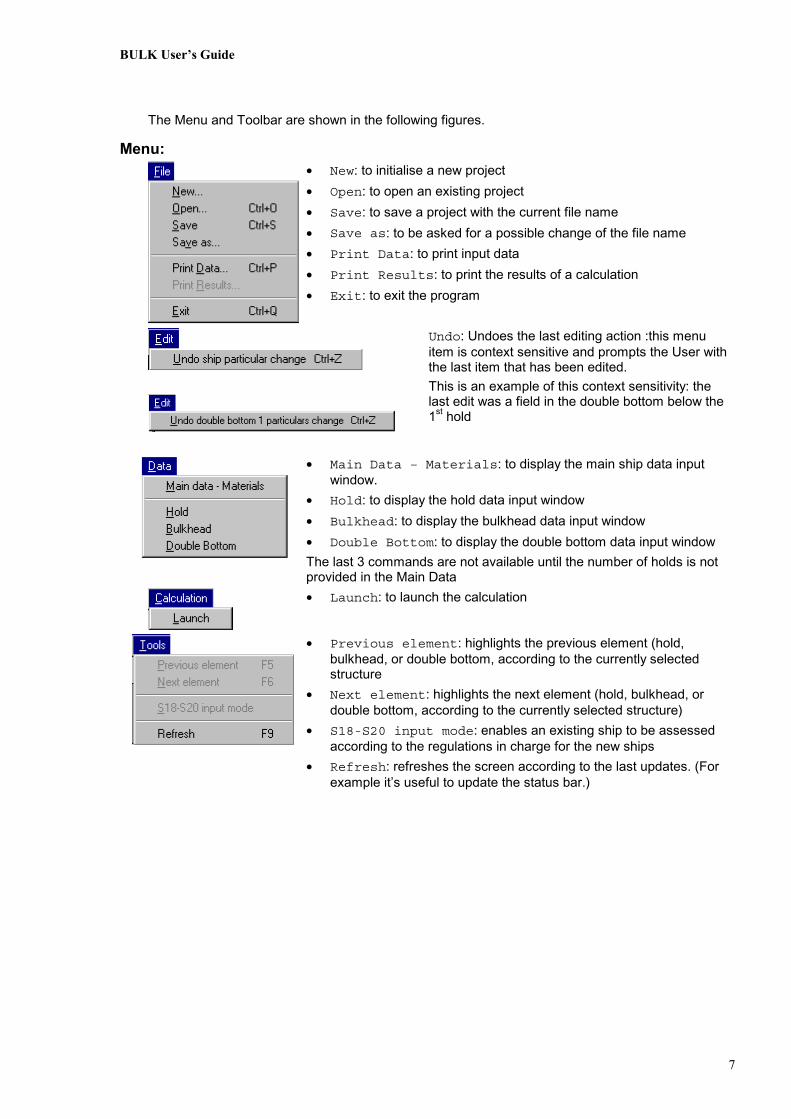
The Menu and Toolbar are shown in the following figures.
Menu:• New: to initialise a new project• Open: to open an existing project• Save: to save a project with the current file name• Save as: to be asked for a possible change of the file name• Print Data: to print input data• Print Results: to print the results of a calculation• Exit: to exit the program
Undo: Undoes the last editing action :this menuitem is context sensitive and prompts the User withthe last item that has been edited. This is an example of this context sensitivity: thelast edit was a field in the double bottom below the1st hold
• Main Data – Materials: to display the main ship data inputwindow.
• Hold: to display the hold data input window• Bulkhead: to display the bulkhead data input window• Double Bottom: to display the double bottom data input window The last 3 commands are not available until the number of holds is notprovided in the Main Data
• Launch: to launch the calculation
• Previous element: highlights the previous element (hold,bulkhead, or double bottom, according to the currently selectedstructure
• Next element: highlights the next element (hold, bulkhead, ordouble bottom, according to the currently selected structure)
• S18-S20 input mode: enables an existing ship to be assessedaccording to the regulations in charge for the new ships
• Refresh: refreshes the screen according to the last updates. (Forexample it’s useful to update the status bar.)

BULK User’s Guide
8
Toolbar:Launches the calculation process; has the same effect than the
menu item
Displays the main ship data and material data tabs; has thesame effect than the menu item
Displays the hold data window. The hold highlighted afterpressing the button is the last activated one; has the same effect thanthe menu item
Displays the bulkhead data window. The bulkhead highlightedafter pressing the button is the last activated ; has the same effectthan the menu item
Displays the double bottom data window. The double bottomhighlighted after pressing the button is the last activated ; has thesame effect than the menu item
Initialises a new project; Has the same effect than the menu item
Opens an existing project; has the same effect than the menuitem
Saves the project with the current name; has the same effectthan the menu item
Prints or previews the input data; has the same effect than themenu item
Print or previews the result data; has the same effect than themenu item
Exits the program BULK; has the same effect than the menuitem
Other Buttons:Add a new element (span areas, strake, cargoes) in an input
sequence
Delete input elements (span areas, strake, cargoes)
These buttons are present in the span area input, strake input and hold input windows
Status Bar:In the lower right part of the screen is always present a status bar that shows history of all the
warnings. An example is displayed hereafter:
3.2 Basic Ship Data
3.2.1 Identification dataThe first steps that must be accomplished while inputting data are:

BULK User’s Guide
9
• to discriminate whether the ship is new or an existing one, in point of view of the IACS UnifiedRequirements defined in 1.1 General.
• to provide the number of holds.All the other fields as Ship’s name and Builder etc. are useful for a correct definition of the
calculation report but are not essential for the calculation.The “File number” field for example may be used for the filing of the paper reports.After the User has input the number of holds and the attribute of existing or new ship, the window
changes. If an existing ship is chosen, as in the following example of a 5 holds bulk carrier only the 1st
hold , bulkhead and double bottom are available to receive input.
Figure 6

BULK User’s Guide
10
Instead if a new ship is chosen, as in the following example of a 7 holds bulk carrier, all the holds,bulkheads and double bottoms are available to receive input.
Figure 7

BULK User’s Guide
11
In any time, the User that is assessing an existing ship may want to calculate it with the new rules.Following this idea, BULK permits to activate a useful feature as may be noticed in the following
figure. All the items are now ready to receive input, not only the foremost ones.To enter in this input mode select “Tools”>”S18S20 input mode” as reminded in the right lower
part of the Identification tab.
Figure 8
From now, the User may click on a relevant item and, by doing this, to highlight it and to have itdisplayed in an appropriate window for data input.
As long as some data are missing, the User simply can’t continue. We have already seen anexample of this: the User may not input any data for the structures until the number of holds is set.

BULK User’s Guide
12
3.2.2 General dataThe general data tab may change according to the existing or new ship attribute.The following figure displays an existing ship one.
Figure 9
For the exact interpretation of the meaning of each field please refer to the relevant section ofBureau Veritas or Registro Italiano Navale rules and to IACS URS when needed.

BULK User’s Guide
13
The following general data tab displays the general data for a new ship.The only difference with an existing ship is that the draught reduction field is not present because
not needed for URS18 calculation.
Figure 10

BULK User’s Guide
14
3.2.3 Material dataIn Figure 11 shown hereafter the User may see an example of input of the material data.
Figure 11
The User may enter up to 6 materials, choosing among those proposed in the list. Themechanical properties that are not greyed may be changed. In the next windows, when asked for amaterial the User will be prompted with a listbox containing all the acronyms of the materials entered inthis tab: an example of this is shown immediately hereafter in Figure 12.
Figure 12

BULK User’s Guide
15
3.3 Hold DataAll the information concerning holds and carried cargoes may be input clicking on the relevant
hold in the ship’s picture.The User should fill the requested fields and add as many cargoes as desiredusing the add button. Then the User may retrieve the relevant data by selecting the cargo in the cargolist box. Obviously the currently selected cargo data may be deleted using the delete button.
The form is vertically divided into two logically separated zones:• the left part concerns the input of geometric data related to the hold.• the right part contains the fields related to the cargo parameters involved in the calculation.
3.3.1 New Ship or Existing Ship calculated as newHereafter follows an example of the windows displayed in the new ship or existing ship calculated
as new condition.
Figure 13
URS18 requires as input data the height of cargo; in any case the software provides a help incase the User wants to estimate the value of the height with some hold geometric data and the massof cargo.

BULK User’s Guide
16
In this case the height wizard control must be selected and the appearance will change asdisplayed in Figure 15. The hold’s breadth must be considered as a mean one (remember that it’s anestimation).
To better explain the subject a detailed description follows:The formula used to calculate the height is based on URS19 (see Figure 14) but the breadth is not
that of amidship and must be decided especially if the transversal geometry of the holdchanges along the hold itself.
Figure 14
This feature has been implemented just to help the User to get a quick estimation of the height,but more sophisticated means may be used to calculate the hold volume;
Figure 15
If Height wizard is selected the height field is no more accessible and is used just to show theresultant height interactively.

BULK User’s Guide
17
3.3.2 Existing ShipFor an existing ship the following figure is displayed.
Figure 16
In this window the Height wizard is not present because the URS19 rule prescribes to calculatethe height of cargo with the formula shown in Figure 14. The “Hold breadth” field is not presentbecause the application refers to the value of breadth amidship entered in the main ship data window.
The only other difference is that one more information is required for URS19 regulation and isdescribed in the following figure.
Figure 17
This information may be essential for the program to know whether to calculate the empty floodedloading case for the foremost bulkhead or not. For new ships the empty flooded loading case iscalculated always, and so this field is not necessary.
For further explanations on this subject, refer to the relevant section in URS19.The User should pay attention to the question asked. The attribute “Carried in a non
homogeneous loading condition” refers to the relevant cargo carried in the hold, while the one “Allowedto be loaded in a non homogeneous loading condition” refers to the foremost hold of an existing ship.
3.4 Bulkhead DataAll the information concerning bulkheads and may be input clicking on the desired bulkhead in the
ship’s picture. After having entered in this window the User should fill the desired fields.

BULK User’s Guide
18
3.4.1 Geometric dataEntering a bulkhead the following window is displayed.
Figure 18
The User should first enter the data concerning the bulkhead geometry.

BULK User’s Guide
19
The following figure shows the various dimensions that may be provided to describe a bulkhead.
Figure 19
It’s important to notice that the dimensions to be provided to the software may be calculated usingthe following formulas.
If a , b and c are provided in the plans, the User should first calculate d with:22 bcd −=
Then the S1 value to be input may be calculated with:S a b1 = +
If the angle ϕ is provided in the plans, together with a and S1 the following formula must be used :
( )d S a= − ⋅1 tan( )ϕThe section moduli are calculated using the formulae contained in RINA (Sez. B I Art. 5.4.1) and
BV (Partie II 5-016 ,12) rules.Little differences between the values calculated with this formula and the ones calculated with
other procedures may arise.
3.4.2 Span area dataClicking on the span area tab the following window will be displayed.After having entered in this windows the User should fill the desired fields and add as many span
areas as desired using the add button. After the User may retrieve the relevant data by selecting thespan areas in the span areas list box. Obviously the currently selected span areas data may be deletedusing the delete button.

BULK User’s Guide
20
Figure 20
The only difference to be noticed in this window between the existing and new ships is that for theexisting ones the thicknesses to be input are the actual while for the new ones are as built ones.
In any case there are reminders in the upper right corners as show hereafter.

BULK User’s Guide
21
3.4.3 Strake dataClicking on the “strakes” tab the following window will be displayed.After having entered in this window the User should fill the relevant fields and add as many
strakes as desired using the add button. Then the User may retrieve the relevant data by selecting thestrake in the strakes list box. Obviously the currently selected strake data may be deleted using thedelete button.
Figure 21
The only difference to be noticed in this window between the existing and new ships is that for theexisting ones the thicknesses to be input are the actual while for the new ones they are as built ones.
In any case there are reminders in the upper right corners as show hereafter.
3.5 Double Bottom DataAll the information concerning double bottoms may be input clicking on the desired double bottom
in the ship’s picture. After having entered in this window the User should fill the relevant fields.This window is organised in 4 tabs. General data, girder data, floor data and local data.It’s important to follow this logic path in order to fully benefit of the easiness in using this GUI.

BULK User’s Guide
22
3.5.1 General double bottom data for new shipsClicking on the “Double bottom n° x” data tab the following window will be displayed.
Figure 22
In this tab the User is asked to input the data concerning the number of floors and girders. Thesedata will be used to create a picture displaying the structural elements that contribute to the shearstrength of a double bottom.
It is important that these data are entered first because some others input depend from them. Forexample is impossible to define the floor spacing before a number of floors is input.
Then the User must enter the spacing of all the floors present in the relevant double bottom.To do this the User should first enter a spacing, then the starting and ending floor to which the
spacing is applied, then press the button. Every different spacing is added to the listboxon the left, so to give immediate feedback.
BULK User’s Guide
23
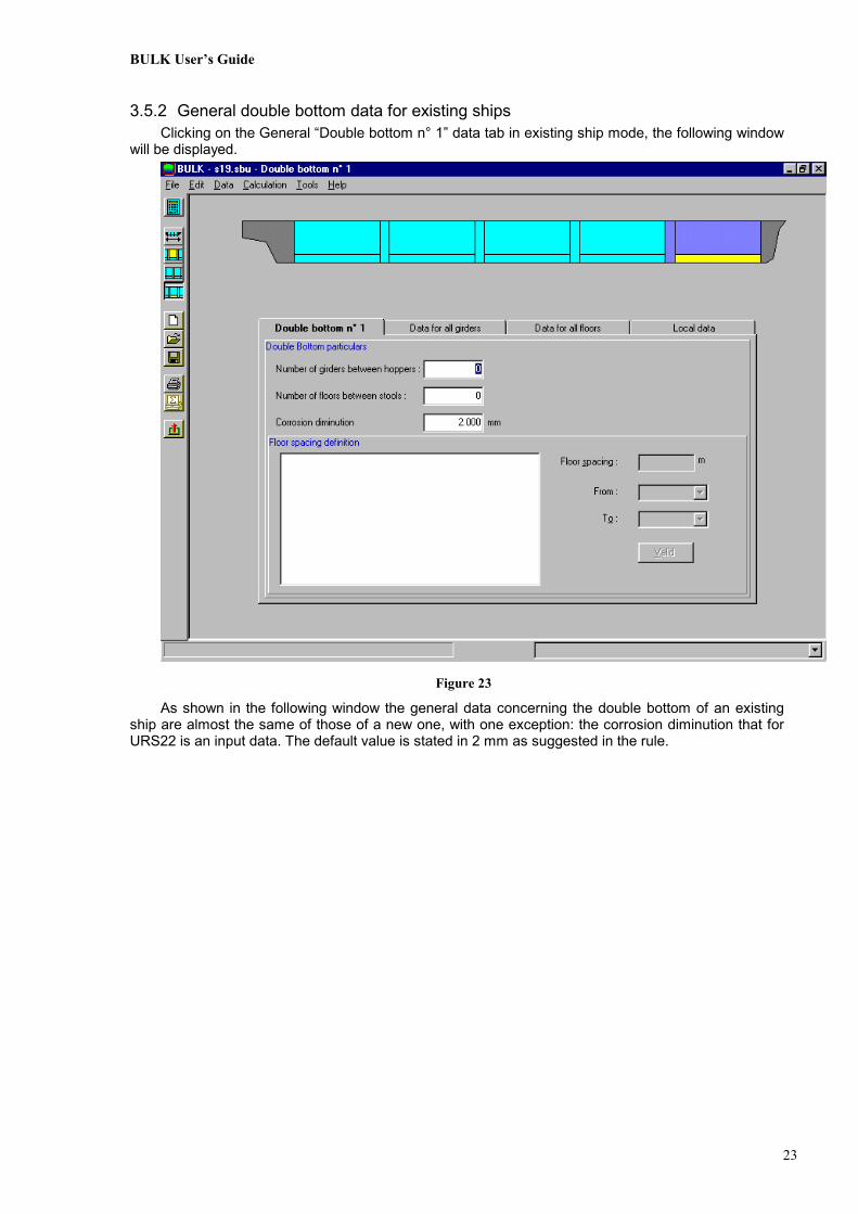
3.5.2 General double bottom data for existing shipsClicking on the General “Double bottom n° 1” data tab in existing ship mode, the following window
will be displayed.
Figure 23
As shown in the following window the general data concerning the double bottom of an existingship are almost the same of those of a new one, with one exception: the corrosion diminution that forURS22 is an input data. The default value is stated in 2 mm as suggested in the rule.

BULK User’s Guide
24
3.5.3 Girder dataAs many girders may have very similar data, BULK asks for the most common data to be input
just once.
Figure 24
The data input in this window will be used for all the girders unless differently stated in the Localdata tab. If the User changes some data in the local data window and then wants to reapply the “allgirder data”, he has to return in this tab and select the Yes options in the following radio buttons.

BULK User’s Guide
25
3.5.4 Floor dataAs many floors may have very similar data, BULK asks for the most common data to be input just
once.
Figure 25
The data input in this window will be used for all the floors unless differently stated in the Localdata tab. If the User changes some data in the local data window and then wants to reapply the “allfloors data”, he has to return in this tab and select the Yes options in the following radio buttons.

BULK User’s Guide
26
3.5.5 Girder and Floor Local dataClicking in the Local Data tab, if the numbers of floors and girders has been entered, the User will
see a grid representing the relevant structure of a double bottom.Clicking on a girder, using the same principle of the ship’s picture, the following window will be
displayed.
Figure 26

BULK User’s Guide
27
Clicking on a floor, using the same principle of the ship’s picture, the following window will bedisplayed.
Figure 27
If the User wants to change some local data, he may select the chosen floor or girder and changethe wrong “most common” data. The “most common” data are always shown in the greyed fields onthe right side.
The “Connected” data allows the User to disconnect the selected item i.e. not takingit into account for strength’s purposes.
To the User is given the possibility of entering directly the sectional areas relevant for thecalculation. In the greyed fields sideways are shown the sectional areas calculated from the “mostcommon” usual data. If the User inputs both a local sectional area and a local thickness or beamheight the value used by the program will be the one of the sectional area.
Hereafter follows a portion of the picture containing the described fields.

BULK User’s Guide
28
4. RUN A CALCULATIONTo calculate relevant items, follow the instructions contained in 6.3 Run a calculation
5. OUTPUT DESCRIPTION
To see the results, the User must click on the button or choose the File>Print Resultsitem on the menu. The following will be displayed:
Figure 28
Select the results and whether they must be Previewed (shown on the screen) or printed (Okbutton)
In browsing the results and data on screen the following logic is used:
• To move from one preview page to the following use the button
• To close the preview window use the button.

BULK User’s Guide
29
5.1 Bulkhead results description
5.1.1 New shipAll the results for bulkheads of new ships are calculated in the hypothesis of 3.5 mm corrosion
margin.The following figure shows the results concerning the net modulus of a bulkhead.The numbers on the left are progressive and represent different span areas, characterised by a
Span and by the input thicknesses and the calculated net thicknesses. The acronyms LE, MI, UEmean lower end, mid span and upper end i.e. the different parts of the bulkhead along the span areas.
The Net Moduli calculated are not the geometric values but those calculated following the IACSrules URS18 and URS19.
Figure 29

BULK User’s Guide
30
The following figure shows the results of the general strength calculations for each scantling areaand each loading condition.
The number on the left is an identification for each scantling area; each loading condition isidentified with an abbreviation i.e. the C (cargo) +number of cargo +H (hold) +number of hold, whileEMP Hx means Hold x empty-flooded loading condition. For every result are shown the outcomes ofthe calculation and the maximum permissible values; if the outcome exceeds the maximumpermissible values an asterisk (*) is printed.
Figure 30

BULK User’s Guide
31
The following figure shows the results of the local strength calculations.The approach is very similar to the scantling area results; the actual thicknesses are those input
by the User, while the application computes the net rule thickness and then (adding 3.5 mm corrosionmargin) the rule thickness. Finally actual and rule thicknesses are compared.
Figure 31
5.1.2 Existing shipsAll the results for existing ships bulkheads are calculated twice, the first time in the hypothesis
of 1 mm corrosion margin and then in the hypothesis of 0.5 mm corrosion margin.This will help the User to better assess the conditions of the structure, and decide how to remedy
weaknesses, if any.Except for this feature the structure of this output is very similar to that of new ships.

BULK User’s Guide
32
The following figure shows the results concerning the net modulus of a bulkhead.
Figure 32

BULK User’s Guide
33
The following figure shows the results of the general strength calculations for each scantling areaand each loading condition.
Figure 33

BULK User’s Guide
34
The following figure shows the results of the local strength calculations.
Figure 34
The results with 0.5 mm corrosion margin are organised the same way, except the followinginformation shown to remind the difference.
The rule thickness displayed in the 4th and 7th column of Figure 34 is that correspondent to 1 mmcorrosion margin and is just intended to be used for comparison with the actual one; the same thingcan be said for the one correspondent to 0.5 mm corrosion margin. The above mentioned “rulethicknesses” have thus meaning only relatively to the corresponding corrosion margin.
It is reminded that, in case the criteria are not satisfied for the gauged thicknesses andreinforcements are thus needed, these reinforcements are to be verified on the basis of their netthicknesses. According to URS19 the as built thickness for the renewed or reinforced parts is the netone +2.5 mm.

BULK User’s Guide
35
5.2 Double bottom resultsThe following figure shows an example of the results available for the double bottoms.
Figure 35
The output is basically constituted by the allowable height of cargoes. The application thencalculates the allowable loading by means of an approximated formula. This value may not be 100%correct for heights of cargoes from the baseline less than that of hopper tanks: it is due to the fact thegeometry of lower stool and the slope of hopper tanks is not taken into account to avoid additionalcomplexity of the input phase.
The only difference between the new and existing ships is the value of the corrosion margin: forURS20 this value is stated in 2.5 mm (see above picture), while for URS22 it’s an input (the defaultvalue is 2 mm as suggested in URS 22).

BULK User’s Guide
36
5.3 Input data
To print the input data press the button or choose File>Print Data.The following window will be displayed:
Figure 36
Select:• Which data to output.• The device will be: Ok for printer , Preview for screen.
As can be noticed all input data provided may be printed.

BULK User’s Guide
37
Hereafter follow some examples of input data prints.Of course BULK may selectively print all the data input by the User, the following ones are just
examples:Example of Basic Ship Data preview.
Figure 37
BULK User’s Guide
38
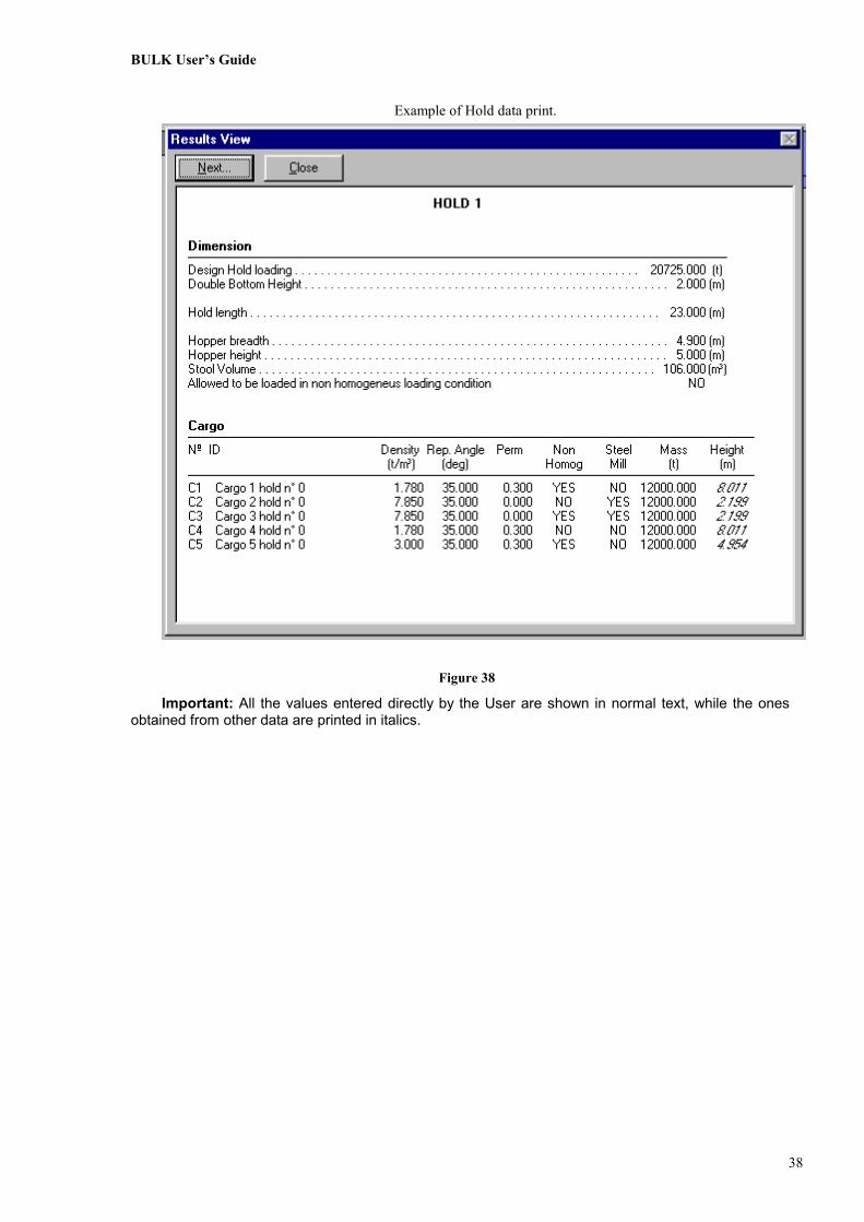
Example of Hold data print.
Figure 38
Important: All the values entered directly by the User are shown in normal text, while the onesobtained from other data are printed in italics.

BULK User’s Guide
39
6. GETTING STARTED
6.1 Execute a new calculationEntering the program (by clicking “New” in the Menu File or the New button of the toolbar), the
User Can introduce the Basic ship data, and must introduce the number of holds which is essential toenter further data.
The first main window is shown in the following figure and all the other interface windows arearranged in the same way.
Figure 39
Each window is divided into three main parts:Part 1: Shows the menu and toolbar and does not change during data input.
The User can select items from the menu and toolbar according to the status of theinterface that changes during the data input process.
Part 2: A “hot” picture of the ship which allows the User to select single items relevant to thiskind of calculation i.e bulkheads, double bottoms and holds. Important: This pictureis initialised only when the number of holds is entered.
Part 3: This area changes on the basis of the item selected by the User.The User may select each element (bulkheads, holds and double bottoms) in theabove picture and input or change the relevant data.A window in the double bottom contains a “hot” picture displaying the floors andgirders of the selected double bottom, with their scantling data.

BULK User’s Guide
40
A detailed description of each window and relevant data is given in 3 INPUT INTERFACEDESCRIPTION.
6.2 Execute a test calculationFollowing installation of the program, two ship examples are given:
Test_Old a bulk carrier to be checked with the URS19 URS22 rulesTest_New a bulk carrier to be checked with the URS18 URS20 rules
The User may load each of these two examples, using the File>Open menu command or theopen button. The User may also start one of the examples by double clicking on its icon in the datadirectory; any file with the .sbu extension will actually start the BULK application.
Using the same procedure given in (in 3 INPUT INTERFACE DESCRIPTION), the User may seeor change the input data relevant to the ship selected.
6.3 Run a calculation
To start the calculation of a ship, press the button or choose theCalculation>Launch command; the program will ask whether bulkheads or double bottoms are to beconsidered in the calculation as shown in the following figure.
Figure 40
To proceed, check the chosen boxes and click on the Next button.If the User is performing a test on more than one structure, he will be asked to choose from
among the present structures the ones to be calculated, as shown in the following figures.
Figure 41
BULK User’s Guide
41
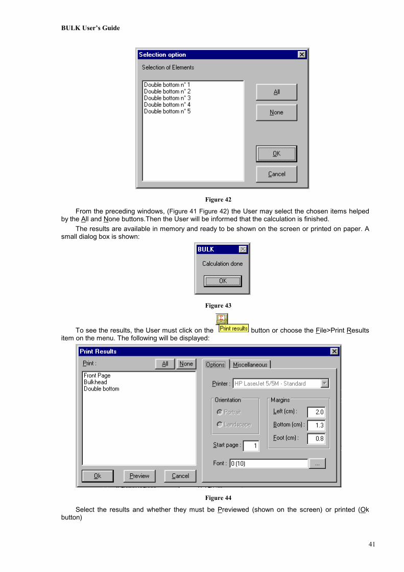
Figure 42
From the preceding windows, (Figure 41 Figure 42) the User may select the chosen items helpedby the All and None buttons.Then the User will be informed that the calculation is finished.
The results are available in memory and ready to be shown on the screen or printed on paper. Asmall dialog box is shown:
Figure 43
To see the results, the User must click on the button or choose the File>Print Resultsitem on the menu. The following will be displayed:
Figure 44
Select the results and whether they must be Previewed (shown on the screen) or printed (Okbutton)