Embed Size (px)
Citation preview


Design and specifications are each subject to change without notice. Ask factory for the current technical specifications before purchase and/or use.
Should a safety concern arise regarding this product, please be sure to contact us immediately.
Built-in Sensor
Water level detection for washing machinePS-A Pressure Sensor (Low pressure type)
Built-in sensor contributes to energy savings, safety, and comfort.Providing sensors for various aspects of our lives.
ON/OFF of exterior lightingNaPiCa (Brightness detection)
ON/OFF of door lightGrid-EYE (Human detection)NaPiCa (Brightness detection)
ON/OFF of garage lightGrid-EYE (Human detection)NaPiCa (Brightness detection)
Car navigation1-axis Acceleration Sensor(Inclination detection)
Occupancy detection, door opening/closingMA Motion Sensor (Position detection)
NaPiCa (Brightness detection)
Increased visibility of LCD TVs and personal computers.
Regular screen
Light turns off when surround-ings are bright.
Dim lighting when it gets dark.
Illumination at 100% when Grid-EYE detects a person nearby.
Returns to dim lighting when person is gone.
Backlight dims when the room gets dark.
ON/OFF of bicycles lightNaPiCa (Brightness detection)
SphygmomanomaterPressure Sensor
(Pressure detection)
ON/OFF of blindsNaPiCa
(Brightness detection)
Security cameraGrid-EYE
(Human detection)
ON/OFF of corridor light
NaPiCa (Brightness detection)
Grid-EYE (Human detection)
Brightness detection of
an electric wave clock
NaPiCa (Brightness
detection)
Air conditioner
Grid-EYE (Human detection)
When it gets light, the clock will set the correct time by reception of radio waves.
TICK
Microwave ovenGrid-EYE (Temperature measurement)
Infrared Array Sensor
Grid-EYE
Human・HeatAcceleration Sensors Light Sensors
Acceleration Brightness
2-axis GS2 1-axis GS1 1-axis GF1 Through-hole type
Aug. 201500

Design and specifications are each subject to change without notice. Ask factory for the current technical specifications before purchase and/or use.
Should a safety concern arise regarding this product, please be sure to contact us immediately.
Built-in Sensor
Automatic lighting in conference roomGrid-EYE (Human detection)NaPiCa (Brightness detection)
Customer detection for automated teller machineMA Motion Sensor (Position detection)
Trapezoidal compensation of LCD projectors1-axis Acceleration Sensor(Inclination detection)
Automatic toilet seat opening/closingMA Motion Sensor (Position detection)
Non-contact switchMA Motion Sensor (Position detection)
ON/OFF of lightingGrid-EYE (Human detection)
Running machineMA Motion Sensor(Position detection)
Motion detection forinstant photography machine
Grid-EYE (Human detection)
Automatic lighting for vending machine
NaPiCa (Brightness detection)
Permit dispenser for parking lotMA Motion Sensor (Position detection)
Security for parking lotGrid-EYE (Human detection)
NaPiCa (Brightness detection)
ON/OFF of street lightNaPiCa (Brightness detection)
Air bedPressure Sensor (Pressure detection)
Automatic doorMA Motion Sensor
(Position detection)
SphygmomanomaterPressure Sensor
(Pressure detection)
Automatic ticket gateMA Motion Sensor
(Position detection)
Motion detection for ticket vending
machineMA Motion Sensor
(Position detection)
Automatic ventilation fanGrid-EYE (Human detection)
Occupancy sensorMA Motion Sensor
(Position detection)
Color mode screen in the day.
Screen switches to night vision mode when it gets dark.
Construction machinery (inclination detection)1-axis Acceleration Sensor
Motion SensorsMotion
Pressure SensorsPressure
Thin short type(V type)
Short type(H type)
Middle type(H type)
Long type(H type)
Long type(V type)
PS
PFPS-A
(Low pressure type)
PS-A
Aug. 201500

Design and specifications are each subject to change without notice. Ask factory for the current technical specifications before purchase and/or use.
Should a safety concern arise regarding this product, please be sure to contact us immediately.
Built-in Sensor Selector Chart
Equipment sensors for improved comfort and convenience, safety and energy conservation
MotionMotion
BrightnessBrightness
AccelerationAcceleration
Making us more comfortable with energy efficient devices...Environmentally friendly, cadmium-free
Made possible by leading-edge MEMS technology, this acceleration sensor is ideal for automotive and mobile devices.
Cadmium-free Built-in optical filter for spectral response
similar to that of the human eye. Photocurrent is proportional to
illumination. (linear output)
Light Sensor
2-axis GS2
1-axis GS1
Product name Peak sensitivity wave length Characteristics
Through-hole type
580nm
±2g ±1.5g
High precision and high sensitivity High reliability: Detection errors due to
temperature fluctuation reduced to a minimum.
Product lineup covers range of operating voltage and acceleration detection.
Product name Acceleration detection range Characteristics
MotionSensors
LightSensors
AccelerationSensors
The sensors are ready for immediate use by simply connecting to a DC power supply. The built-in oscillation circuit removes the need to input a start signal.
Can be used with a number of different supply voltages. 1) 5 V.DC type (4.5 V.DC to 5.5 V.DC) 2) Free-ranging type (5.5 V.DC to 27 V.DC)
These sensors can be used in adjacent positions and can save energy.
Can be used with a number of different supply voltages. 1) 5 V.DC type (4.5 V.DC to 5.5 V.DC) 2) Free-ranging type (5.5 V.DC to 27 V.DC)
MA Motion Sensor
Short type(H type)
Thin shorttype (V type)
Middle type(H type)
Long type (H type) Long type (V type)
Sensor
Detectiondistance
5 cm to 200 cm1.969 inch to
78.74 inch
Detectiondistance
5 cm to 200 cm1.969 inch to
78.74 inch
Built-in oscillation circuit type
External trigger type
Detecting the presence of the human body (or another object) by the reflected beam of LED light from the sensor itself.
Ligh
t Sen
sor
Acc
eler
atio
n Se
nsor
1-axis GF1 Fast response, high reliability Compact size
±0.5g ±1.2g
Direct mount Bracket
Motion sensors that always detect your slightest movementProduct name Detection method Type Characteristics
Are
a re
flect
ive
type
Mot
ion
Sens
or
Aug. 201500

Design and specifications are each subject to change without notice. Ask factory for the current technical specifications before purchase and/or use.
Should a safety concern arise regarding this product, please be sure to contact us immediately.
Built-in Sensor Selector Chart
PressurePressure A wide range of rated pressure, including minute pressuresProduct name
Air
Ultra-miniature Base area 7.2 (W) x 7.2 (D) mm .283 (W) x .283 (D) inch
A wide range of rated pressure, including a minute pressure.
Pressuremedium Type (*Without glass base type)
Rated pressure
Terminaldirection
Pressure inlethole length
Bridge resistance
Characteristics
PS-A Pressure Sensor
PS Pressure SensorPF Pressure Sensor
Air
Low pressure type ideal for water level detection applications added to lineup.
Compact pressure sensor with built-in amplification and temperature compensation circuit
Rated pressure
*40kPa98.1, 980.7kPa
(PS only)
3mm
5mm
5mm3mm dia.
13.5mm5.45mm dia.
200, 500, 1,000 *40kPa
<Low pressure type>6kPa
4.9, 34.3, 49.0, 98.1, 196.1, 343.2, 490.3, 833.6, 980.7 kPa
PressureSensors
Pres
sure
Sen
sors
High Precision Infrared Array Sensor based on Advanced MEMS Technology
Grid-EYE
Product name Detection method Type Characteristics
Ther
mop
ile ty
pe
Sensor
Detecting the heat (infrared rays) of the human body and other objects.
InfraredArray
Sensor
Amplification factorHigh gainLow gain
Operating voltage3.3 V.DC5.0 V.DC
HeatHeatIn
frar
ed A
rray
Sen
sors
Temperature detection achieved on a two dimensional area with 8 × 8 (64) pixels.
Digital output Miniature SMD package
Opposite thepressure inlet
direction
(SMD terminal)
(SMD terminal)
Opposite thepressure inlet
direction
Pressure inlet direction
Aug. 201500

Design and specifications are each subject to change without notice. Ask factory for the current technical specifications before purchase and/or use.
Should a safety concern arise regarding this product, please be sure to contact us immediately.
GS2 Sensor (AGS2)
Number of detectable axis (Method)
Package type/Size
2-axis Acceleration Sensor (Electrostatic capacitance type)
:2
Operation power supply voltage/Output type
3 V.DC/Analog output5 V.DC/Analog output
::
35
TypeBuilt-in ASIC:1Ceramic package/6.2 × 8.5 mm:1 :
:::
Detection sensitivity1 V/g1.333 V/g0.6 V/g0.8 V/g
1368
AGS 2 1 1
High-precision MEMS2-axis acceleration sensor
GS2 SENSOR
● High precision, high reliability : offset temperature characteristics ±38 mg (Typ.)● High sensitivity : 1 to 1.333 V/g(5 V.DC)● Line-up for various operating power supply voltages and acceleration detection ranges.● RoHS compliant
● Car Electronics : Car navigation systems, Car security, Drive recorders● Ships and special vehicles : Marine equipment, construction/agricultural machines and welfare vehicles● Other : Theft prevention for faculty equipment, Measuring devices (levels, measuring instruments)
Features
Typical Applications
Ordering Information
Product nameOperation power
supply voltage
Acceleration
detection rangeDetection sensitivity Part number
2-axis
Acceleration sensor GS2
3 V.DC±2 g 0.6V/g AGS21631
±1.5 g 0.8V/g AGS21831
5 V.DC±2 g 1V/g AGS21151
±1.5 g 1.333V/g AGS21351
Name UnitAbsolute maximum ratings
RemarksMin. Typ. Max.
Max. applied voltage V –0.3 − 7 Ta=25 °C 77 °F
Storage temperature range °C °F –40 –40 − 85 185
Operation temperature range °C °F –40 –40 − 85 185
Anti-shock characteristic g − − 5,000
Types
Absolute Maximum Ratings
X-axisY-axis
: Direction of acceleration detection
Standard packing : Carton : 1,000 pcs.
Aug. 201500

Design and specifications are each subject to change without notice. Ask factory for the current technical specifications before purchase and/or use.
Should a safety concern arise regarding this product, please be sure to contact us immediately.
GS2 Sensor (AGS2)
−1.0 −0.5 0.0 0.5 1.01.0
1.5
2.0
2.5
3.0
3.5
4.0
Acceleration (g)
Ou
tpu
t vo
ltag
e (
V)
−5
−4
−3
−2
−1
0
1
2
3
4
5
−40 −20 0 20 40 60 80 100−40 −4 +32 +68 +104 +140 +176 +212
Temperature (°C °F)
Sens
itivi
ty c
hang
e (m
easu
red
valu
e) (%
)
−100 −80 −60 −40 −20 20 40 60 80 10001.0
1.5
2.0
2.5
3.0
3.5
4.0
Inclination angle ( °)
Ou
tpu
t vo
ltag
e (
V)
−100
−80
−60
−40
−20
0
20
40
60
80
100
−40 −20 0 20 40 60 80 100−40 −4 +32 +68 +104 +140 +176 +212
Temperature (°C °F)
Offse
t volt
age
chan
ge (m
easu
red
value
) (m
g)
−5−4
−3
−2
−1
0
1
2
3
4
5
−40 −20 0 20 40 60 80 100−40 −4 +32 +68 +104 +140 +176 +212
Temperature (°C °F)
Sens
itivi
ty c
hang
e (m
easu
red
valu
e) (%
)
−100
−80
−60
−40
−20
0
20
40
60
80
100
−40 −20 0 20 40 60 80 100−40 −4 +32 +68 +104 +140 +176 +212
Temperature (°C °F)
Offse
t volt
age
chan
ge (m
easu
red
value
) (m
g)
Item Unit
Performance
RemarksMin. Typ. Max.
AGS21151
AGS21351
AGS21631
AGS21831
AGS21151
AGS21351
AGS21631
AGS21831
AGS21151
AGS21351
AGS21631
AGS21831
Acceleration detection range ✽1 g −2 −1.5 −2 −1.5 − 2 1.5 2 1.5
Operation power supply voltage
V.DC 4.75 2.85 5 3 5.25 3.15−40 °C to +85 °C–40 °F to +185 °F
Current consumption mA − − 2 1.8 5 5 0g, Ta=25 °C 77 °F
Sensitivity V/g 0.975 1.3 0.585 0.78 1 1.333 0.6 0.8 1.025 1.366 0.615 0.82 Ta=25 °C 77 °F
Offset voltage (0 g) V 2.44 2.42 1.464 1.452 2.5 1.5 2.56 2.58 1.536 1.548 Ta=25 °C 77 °F
Temperature sensitivity characteristic
% −2 − 2−40 °C to +85 °C–40 °F to +185 °F
Offset voltage temperaturecharacteristic
mg −55 − 55−40 °C to +85 °C–40 °F to +185 °F
Other axis sensitivity ✽2 % −5 − 5 Ta=25 °C 77 °F
Non-linearity ✽3 %FS −1 − 1 Ta=25 °C 77 °F
Turn-on time ✽4 ms − 10 −0g, Ta=25 °C 77 °F
C1=220 nF, C2, C3=27 nF
Frequency response Hz DC − 60−3 dB point,C2=27 nF
Notes : ✽1 The acceleration unit “g” means 9.8 m/s2.
✽2 VDD typical value of each part number when nothing is specifi ed. ✽3 Maximum error from linear output that connects +2 g and –2 g output. (AGS21151, AGS21631) Maximum error from linear output that connects +1.5 g and –1.5 g output. (AGS21351, AGS21831) ✽4 “C1” is a ceramic capacitor installed between the VDD and GND terminals. “C2” is a ceramic capacitor installed between the Vout (X) and Ext-Cap (X) terminals. “C3” is a ceramic capacitor installed between the Vout (Y) and Ext-Cap (Y) terminals. ✽5 The frequency characteristics can be changed depending on the C2 and C3 capacitance value. Please refer to “Recommended circuit diagram” on the following page. Note that the maximum frequency response is 60 Hz
1. Output characteristics (AGS21151)
3.-2 Sensitivity temperature characteristics Y-axis (5 V.DC)
2. Inclination angle - Output voltage characteristics (AGS21151)
4.-1 Offset voltage temperature characteristics X-axis (5 V.DC)
3.-1 Sensitivity temperature characteristics X-axis (5 V.DC)
4.-2 Offset voltage temperature characteristics Y-axis (5 V.DC)
Electrical Characteristics
Reference DataReference Data
Aug. 201500

Design and specifications are each subject to change without notice. Ask factory for the current technical specifications before purchase and/or use.
Should a safety concern arise regarding this product, please be sure to contact us immediately.
GS2 Sensor (AGS2)
Frequency (Hz)1 10 60 100
−7.00
−6.00
−5.00
−4.00
−3.00
−2.00
−1.00
0.00(C2,C3=27 nF)
Ga
in (
dB
)
4-0.08 4-0.424-0.003 4-0.017
P1.27×4P0.500×4
1.2
0.0
47
10-0.510-0.020
1.6
±0
.20.
063±
0.00
8
Partnumber
Lot number
6.2
±0
.20
.24
4±
0.0
08
8.5±0.20.335±0.008
8
71
8
71
141001
AGS21151
14
14
8.1±0.05
0.9
0.0
35
6.9
0.2
72
0.8 0.80.70.031 0.0310.028
P1.27±0.05×4=5.08
0.319±0.002
P0.050±0.002×4=0.200
6.7±0.10.264±0.004
9.0
±0.1
0.3
54±
0.0
04
0.3±0.050.012±0.002
1.5
±0.1
dia
.0.
059+
0.00
4 d
ia.
1.95±0.20.077±0.008
1.5+0.1 dia.0
0.059+0.004 dia.0
12.0
±0.1
4.0
±0
.1
1.75±0.15.5±0.050.069±0.0040.217±0.002
12.0±0.20.472±0.008
2.0
±0.0
5
0.4
72±
.004
0.15
7±.0
040.0
79±
0.0
02
14
10
01
Direction o
f p
ickin
g
AG
S2115
114
10
01
AG
S21151
13.4±1
17.4±1
0.528±0.039
0.685±0.039
Embossed carrier tape
Top cover tape
80±1 dia.3.150±0.039 dia.
21±0.8 dia. 0.827±0.031 dia.
13±0.2 dia. 0.512±0.008 dia.2.0±0.50.079±0.020
80±1
dia
.
3.1
50
±0
.03
9 d
ia.
25
4±
2 d
ia.
10
.00
0±
0.0
79
dia
.
Recommended Circuit Diagram
Packing Format (Tape And Reel)
Number Terminal Name
1 NC
2 GND
3 NC
4 Vout(X)
5 Ext-Cap(X)
6 GND
7 NC
Number Terminal Name
8 NC
9 VDD
J Ext-Cap(Y)
K Vout(Y)
L NC
M NC
N NC
Leave terminal “NC (No. 1, 3, 7, 8 and 12 to 14)”
unconnected.
The No. 2 and No. 6 terminals are connected internally.
Dimensions
The CAD data of the products with a mark can be downloaded from: http://industrial.panasonic.com/
5. Frequency characteristics
Note : The frequency characteristics can be changed depending on the C2,C3 capacitance value. Please refer to “Recommended circuit diagram” on the following page.
Recommended PC board pad
unit : mm inch
5 V.DC
C1:220 nFMin.
VDD Vout(X) SensorOutput(X)
SensorOutput(Y)
Ext-Cap(X)
Vout(Y)
Ext-Cap(Y)
GND
C2 : 27 nF
The frequency characteristics value can be changeddepending on the C2 and C3 capacitance value.−3dB bandwidth is expressed in the formula below.
f-3dB=2π×(100 kΩ)×(C2 or C3)
1C3 : 27 nF
Tape dimensions Dimensions of tape reel
General tolerance : ±0.1 ±0.04
General tolerance : ±0.1 ±0.04unit : mm inch
Aug. 201500

Design and specifications are each subject to change without notice. Ask factory for the current technical specifications before purchase and/or use.
Should a safety concern arise regarding this product, please be sure to contact us immediately.
GS2 Sensor (AGS2)
T1
T2
T3
t1 t2
NOTES
■ Before use, carefully check theperformance and quality under actualuse conditions to enhance stability.
■ Mounting• Use the land of the printed-circuit boardon which
the sensor is securely fixed.• A large noise on the power supply may cause
malfunction. Place the recommended capacitor near the sensor (within 20 mm 0.787 inch of the wiring pattern length) between sensor input terminals (VDD-GND) to secure power superimposed noise resistance. Test with the actual machine and re-select the capacitor with optimal capacitance.
• Prevent the metal par t of other electronic components from contacting with the sensor body as the upper face (where part numbers are imprinted) of the sensor is GND.
■ Soldering• When soldering, avoid the external thermal
influence. Heat deformation may damage the sensor or deteriorate its performance.
• Use the non-corrosive rosin flux.1) Manual soldering
• Raise the temperature of the soldering tip between 350 and 400 °C 662 and 752 °F (30 and 60W) and solder within 3 seconds.
• The sensor output may vary if the load is applied on the terminal during soldering.
• Keep the soldering tip clean.2) Reflow soldering
Below are recommended temperature profiles/conditions of reflow.• When printing cream solder, the screen
printing method is recommended.• For the foot pattern, see the recommended
diagram of the printed-circuit board.• Carefully align the terminal with the pattern
as self-alignment may not be reliable.• The temperature of the profile is the value
measured near the terminal on the printed-circuit board.
• After reflowing, when performing reflow soldering on the back surface of the circuit board, use an adhesive to fix the board.
3) Rework soldering• Complete rework at a time.• Use a f l a t t ened so lde r i ng t i p when
performing rework on the solder bridge. Do not add the flux.• Keep the soldering tip below the temperature
described in the specifications.4) After soldering, do not apply stress on the soldered
part when cutting or bending the circuit board.5) Prevent human hands or metal pieces from
contacting with the sensor terminal. Such contact may cause anomalous outlets as the terminal is exposed to the atmosphere.
6) After soldering, prevent chemical agents from adhering to the sensor when applying coating to avoid insulation deterioration of the circuit board.3. Maximum applied pressure The maximum pressure that can be applied to the pressure sensor, after which, when the pressure is returned to below the rated pressure range, the specifications of the pressure sensor are guaranteed.
T1 = 150 to 180 °C 302 to 356 °FT2 = 230 °C 446 °FT3 = Below 250 °C 482 °Ft1 = 60 to 120 sec.t2 = Less than 30 sec.
■ Wire connection• Correctly wire as in the connection diagram.
Reverse connection may damage the product and degrade the performance.
• Do not connect wires with NC terminals. Such connection may damage the sensor.
■ CleaningAvoid ul trasonic cleaning as this maycause disconnection of the wire.
■ Environment• Avoid use and storage in the corrosive gas (organic
solvent, sulfurous acid and hydrogen sulfide gases) which negatively affects the product.
• When install ing the sensor, also install the capacitor as in the connection diagram.
• Use surge absorbers as applying the external surge voltage may damage the internal circuit.
• Malfunction may occur near electric noises from static electricity, lightning, broadcast or amateur radio stations and mobile phones.
• Avoid use in a place where these products come in contact with water.
• Avoid use in an environment where these products cause dew condensation. When water attached to the sensor chip freezes, the sensor output may be fluctuated or damaged.
• Do not apply high-frequency oscillation, such as ultrasonic waves, to the product.
■ Other precautionsThese specifications are for individual components. Before use, carefully checkthe performance and quality under actual use conditions to enhance stability.• Once the individual sensor is dropped, do not
use. Drop may cause functional disorders.• Misconnection and the wrong acceleration sensing
range may invite the risk of accidents.• Ensure that using acceleration is within the rated range.
Use beyond the range may damage the product.• Follow the instructions below as static electricity
may damage the product.(1) For storage and transportation, avoid plastic
containers which are easily electrified.(2) When storing and transporting the sensor,
choose the environment where static electricity is hardly generated (e.g., humidity between 45 and 60 %) and protect the product by using electroconductive packaging materials.
(3) Once unpacked, perform antistatic countermeasures.• Operators handling sensors must wear antistatic
cloths and human body grounding devices.• Cover the surface of workbench by electro-
conductive plates and ground measuring instruments and jigs.
• Use the soldering iron which has a small leakage current or ground the soldering tip.
• Ground the assembling equipment.
Aug. 201500

Design and specifications are each subject to change without notice. Ask factory for the current technical specifications before purchase and/or use.
Should a safety concern arise regarding this product, please be sure to contact us immediately.
GS2 Sensor (AGS2)
(4) Use surge absorbers as applying the external surge voltage may damage the internal circuit.
(surge resistance: power supply voltage as in the absolute maximum rating)
■ Special notesWe exert maximum efforts for quality control of the product, Please mind also about the following.
1) To preven t occur rence o f unexpected circumstances, please inform us of the specifications of your product, customers, use conditions and details of the attachment position.
2) Have sufficient margin values of driving/performance guarantee described in the specifications and apply safety measures with double circuits, if serious effects on human lives or property are predicted due to a quality failure of the product. Those countermeasures are also for the product liability.
3) A warranty period is one year after the delivery to your company. Quality assurance is limited to the i tems and the scopes described in the specifications. If a defect is found after the delivery, we will promptly provide a replacement or change/repair the defect part at the place of delivery in good faith. Exceptions are below.• Damages by a failure or a defect which
arose after the delivery.• Af ter the de l ivery, when s tor ing and
t ranspor t ing, i f condi t ions other than conditions in the specifications are applied to the product.
• Damages by unforeseen phenomenon which cannot be predicted with the technologies available at the time of delivery.
• Damages by natural and anthropogenic disasters, such as earthquake, flood, fire and war, which are beyond our reasonable control.
Aug. 201500
Design and specifications are each subject to change without notice. Ask factory for the current technical specifications before purchase and/or use.
Should a safety concern arise regarding this product, please be sure to contact us immediately.
GS1 Sensor (AGS1)
Number of detectable axis (Method)
Package type/Size
1-axis Acceleration Sensor(Electrostatic capacitance type)
:1
Operation power supply voltage/Output type
5 V.DC/Analog output:5
TypeBuilt-in ASIC:1Ceramic package/6.2 × 8.5 mm:1 :
:
Detection sensitivity1 V/g1.333 V/g
13
AGS 1 1 15
High-precision MEMS1-axis acceleration sensor
GS1 SENSOR
● High precision, high reliability : Offset temperature characteristics ±47 mg (Typ.)● High sensitivity : 1 to 1.333 V/g (5 V.DC)● RoHS compliant
● Car navigation systems● Projectors (trapezoidal distortion correction)● Elevators, welfare equipment (inclination detection)
Features
Typical Applications
Ordering Information
Product nameOperation power
supply voltage
Acceleration
detection rangeDetection sensitivity Part number
1-axis
Acceleration sensor GS15 V.DC
±2 g 1 V/g AGS11151
±1.5 g 1.333 V/g AGS11351
Name UnitAbsolute maximum ratings
RemarksMin. Typ. Max.
Max. applied voltage V –0.3 − 7 Ta=25 °C 77 ° F
Storage temperature range °C ° F –40 –40 − 85 185
Operation temperature range °C ° F –40 –40 − 85 185
Anti-shock characteristic g − − 5,000
Types
Absolute Maximum Ratings
Standard packing : Carton : 1,000 pcs.
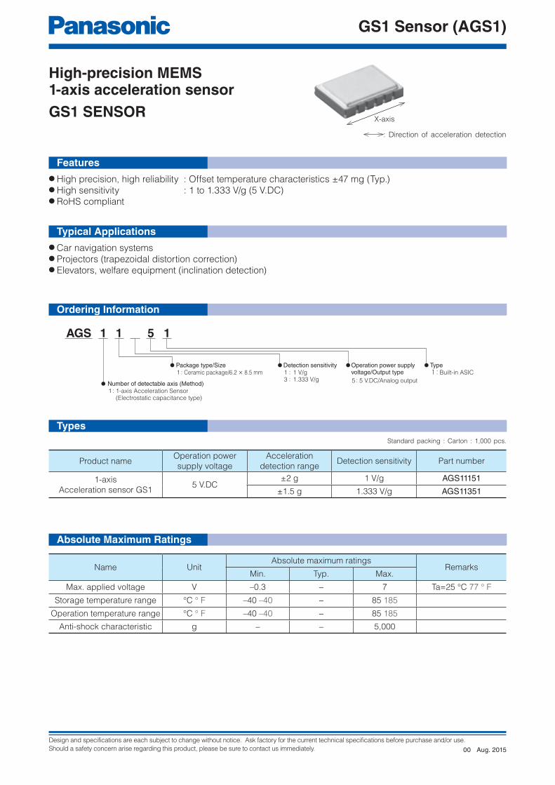
X-axis
: Direction of acceleration detection
Aug. 201500

Design and specifications are each subject to change without notice. Ask factory for the current technical specifications before purchase and/or use.
Should a safety concern arise regarding this product, please be sure to contact us immediately.
GS1 Sensor (AGS1)
−1.0 −0.5 0.0 0.5 1.01.0
1.5
2.0
2.5
3.0
3.5
4.0
Acceleration (g)
Ou
tpu
t vo
ltag
e (
V)
−100
−80
−60
−40
−20
0
20
40
60
80
100
−40 −20 0 20 40 60 80 100−40 −4 +32 +68 +104 +140 +176 +212
Temperature (°C °F)
Offse
t volt
age
chan
ge (m
easu
red
value
) (m
g)
−100 −80 −60 −40 −20 20 40 60 80 10001.0
1.5
2.0
2.5
3.0
3.5
4.0
Inclination angle ( °)
Ou
tpu
t vo
ltag
e (
V)
Frequency (Hz)1 10 60 100
−7.00
−6.00
−5.00
−4.00
−3.00
−2.00
−1.00
0.00(C2=27 nF)
Gain
(d
B)
−5
−4
−3
−2
−1
0
1
2
3
4
5
−40 −20 0 20 40 60 80 100−40 −4 +32 +68 +104 +140 +176 +212
Temperature (°C °F)
Sens
itivi
ty c
hang
e (m
easu
red
valu
e) (%
)
Item Unit
Performance
RemarksMin. Typ. Max.
AGS21151 AGS21351 AGS21151 AGS21351 AGS21151 AGS21351Acceleration detection range ✽1 g −2 −1.5 − 2 1.5
Operation power supply
voltageV.DC 4.75 5 5.25
−40 °C to +85 °C–40 °F to +185 °F
Current consumption mA − 2 5 0g, Ta=25 °C 77 °F
Sensitivity V/g 0.97 1.293 1 1.333 1.03 1.373 Ta=25 °C 77 °F
Offset voltage (0 g) V 2.4 2.5 2.6 Ta=25 °C 77 °F
Temperature sensitivity
characteristic% −4 − 4
−40 °C to +85 °C–40 °F to +185 °F
Offset voltage temperature
characteristicmg −70 − 70
−40 °C to +85 °C–40 °F to +185 °F
Other axis sensitivity ✽2 % −5 − 5 Ta=25 °C 77 °F
Non-linearity ✽3 %FS −1 − 1 Ta=25 °C 77 °F
Turn-on time ✽4 ms − 10 −0g, Ta=25 °C 77 °FC1=220 nF, C2=27 nF
Frequency response ✽5 Hz DC 60 −−3 dB point,C2=27 nF
Notes : ✽1 The acceleration unit “g” means 9.8 m/s2. ✽2 VDD=5 V when there is no indication. ✽3 Maximum error from linear output that connects +2 g and –2 g output. (AGS11151) Maximum error from linear output that connects +1.5 g and –1.5 g output. (AGS11351) ✽4 “C1” is a ceramic capacitor installed between the VDD and GND terminals. “C2” is a ceramic capacitor installed between the Vout and Ext-Cap terminals. ✽5 The frequency characteristics can be changed depending on the C2 capacitance value. Please refer to “Recommended circuit diagram” on the
following page. Note that the maximum frequency response is 200 Hz.
Electrical Characteristics
Note : The frequency characteristics can be changed depending on the C2 capacitance value. Please refer to “Recommended circuit diagram” on the following page.
1. Output characteristics (AGS11151)
2. Inclination angle - Output voltage characteristics (AGS11151)
3. Sensitivity temperature characteristics (5 V.DC)
4. Offset voltage temperature characteristics (5 V.DC)
5. Frequency characteristics
Reference Data
Aug. 201500

Design and specifications are each subject to change without notice. Ask factory for the current technical specifications before purchase and/or use.
Should a safety concern arise regarding this product, please be sure to contact us immediately.
GS1 Sensor (AGS1)
6.7±0.10.264±0.004
9.0
±0.1
0.3
54±
0.0
04
0.3±0.050.012±0.002
1.5
±0.1
dia
.0.0
59±
0.0
04 d
ia.
1.95±0.20.077±0.008
12.0
±0.1
4.0
±0
.1
1.75±0.15.5±0.05
12.0±0.2
0.069±0.0040.217±0.002
0.472±0.008
2.0
±0.0
5
0.4
72±
0.0
04
0.15
7±0.
004
0.07
9±0.
002
14
10
01
Dire
ctio
n o
f p
ickin
g
AG
S11151
14
10
01
AG
S11151
1.5+0.1 dia.0
0.59+0.004 dia.0
13.4±1
17.4±1
0.528±0.039
0.685±0.039
Embossed carrier tape
Top cover tape
80±1 dia.3.150±0.039 dia.
21±0.8 dia. 0.827±0.031 dia. 13±0.2 dia. 0.512±0.008 dia.2.0±0.5
0.079±0.020
80±1
dia
.
3.1
50
±0
.03
9 d
ia.
25
4±
2 d
ia.
10
.00
0±
0.0
79
dia
.
4-0.08 4-0.42
P1.27×4
P0.500×4
1.2
0.04
7
10-0.54-0.003 4-0.017 10-0.020
1.6
±0.2
Lot number
6.2
±0
.20.
063±
0.00
80
.24
4±
0.0
08
8.5±0.20.335±0.008
8
71
8
71
141001
AGS11151
14
14
Partnumber
8.1±0.05
0.9
0.0
35
6.9
0.2
72
0.8 0.80.70.031 0.0310.028
P1.27±0.05×4=5.08
0.319±0.002
P0.050±0.002×4=0.200
Dimensions
The CAD data of the products with a mark can be downloaded from: http://industrial.panasonic.com/
Tape dimensions Dimensions of tape reel
5 V.DC
C1:
220 nF
Min.
VDD Vout
GNDExt
-Cap
Sensor
Output
C2:
27 nF
The frequency characteristics value can be changed
depending on the C2 capacitance value.
-3dB bandwidth is expressed in the formula below.
f-3dB=2π×(100 kΩ)×C2
1
Recommended Circuit Diagram
Packing Format (Tape And Reel)
Number Terminal Name
1 NC
2 GND
3 NC
4 Vout
5 Ext-Cap
6 GND
7 NC
Number Terminal Name
8 NC
9 VDD
J NC
K NC
L NC
M NC
N NC
Leave terminal “NC (No. 1, 3, 7, 8 and 10 to 14)”
unconnected.
The No. 2 and No. 6 terminals are connected internally.
General tolerance : ±0.1 ±0.04
General tolerance : ±0.1 ±0.04
unit : mm inch
unit : mm inch
Recommended PC board pad
Aug. 201500

Design and specifications are each subject to change without notice. Ask factory for the current technical specifications before purchase and/or use.
Should a safety concern arise regarding this product, please be sure to contact us immediately.
GS1 Sensor (AGS1)
T1
T2
T3
t1 t2
NOTES
■ Before use, carefully check the performance and quality under actual use conditions to enhance stability.
■ Mounting• Use the land of the printed-circuit board on which
the sensor is securely fixed.• A large noise on the power supply may cause
malfunction. Place the recommended capacitor near the sensor (within 20 mm 0.787 inch of the wiring patternlength) between sensor input terminals (VDD-GND) to secure power superimposed noise resistance. Test with the actual machine and re-select the capacitor with optimal capacitance.
• Prevent the metal par t of other electronic components from contacting with the sensor body as the upper face (where part numbers are imprinted) of the sensor is GND.
■ Soldering• When soldering, avoid the external thermal
influence. Heat deformation may damage the sensor or deteriorate its performance.
• Use the non-corrosive rosin flux.1) Manual soldering
• Raise the temperature of the soldering tip between 350 and 400 °C 662 and 752 °F (30 and 60 W) and solder within 3 seconds.
• The sensor output may vary if the load is applied on the terminal during soldering.
• Keep the soldering tip clean.2) Reflow soldering
Below are recommended temperature profiles/conditions of reflow.• When printing cream solder, the screen
printing method is recommended.• For the foot pattern, see the recommended
diagram of the printed-circuit board.• Carefully align the terminal with the pattern
as self-alignment may not be reliable.• The temperature of the profile is the value
measured near the terminal on the printed-circuit board.
• After reflowing, when performing reflow soldering on the back surface of the circuit board, use an adhesive to fix the board.
3) Rework soldering• Complete rework at a time.• Use a f l a t t ened so lde r i ng t i p when
performing rework on the solder bridge. Do not add the flux.• Keep the soldering tip below the temperature
described in the specifications.4) After soldering, do not apply stress on the
soldered part when cutting or bending the circuit board.
5) Prevent human hands or metal pieces from contacting with the sensor terminal. Such contact may cause anomalous outlets as the terminal is exposed to the atmosphere.
6) After soldering, prevent chemical agents from adhering to the sensor when applying coating to avoid insulation deterioration of the circuit board.
T1 = 150 to 180 °C 302 to 356 °FT2 = 230 °C 446 °FT3 = Below 250 °C 482 °Ft1 = 60 to 120 sec.t2 = Less than 30 sec.
■ Wire connection• Correctly wire as in the connection diagram.
Reverse connection may damage the product and degrade the performance.
• Do not connect wires with NC terminals. Such connection may damage the sensor.
■ CleaningAvoid ultrasonic cleaning as this may cause disconnection of the wire.
■ Environment• Avoid use and storage in the corrosive gas
(organic solvent, sulfurous acid and hydrogen sulfide gases) which negatively affects the product.
• When install ing the sensor, also install the capacitor as in the connection diagram.
• Use surge absorbers as applying the external surge voltage may damage the internal circuit.
• Malfunction may occur near electric noises from static electricity, lightning, broadcast or amateur radio stations and mobile phones.
• Avoid use in a place where these products come in contact with water.
• Avoid use in an environment where these products cause dew condensation. When water attached to the sensor chip freezes, the sensor output may be fluctuated or damaged.
• Do not apply high-frequency oscillation, such as ultrasonic waves, to the product.
■ Other precautionsThese specifications are for individual components. Before use, carefully check the performance and quality under actual use conditions to enhance stability.• Once the individual sensor is dropped, do not
use. Drop may cause functional disorders.• Misconnection and the wrong acceleration sensing
range may invite the risk of accidents.• Ensure that using acceleration is within the rated range.
Use beyond the range may damage the product.• Follow the instructions below as static electricity
may damage the product.(1) For storage and transportation, avoid plastic
containers which are easily electrified.(2) When storing and transporting the sensor,
choose the environment where static electricity is hardly generated (e.g., humidity between 45 and 60 %) and protect the product by using electroconductive packaging materials.
(3) Once unpacked, perform antistatic countermeasures.• Operators handling sensors must wear
antistatic cloths and human body grounding devices.
• Cover the surface of workbench by electro-conductive plates and ground measuring instruments and jigs.
• Use the soldering iron which has a small leakage current or ground the soldering tip.
• Ground the assembling equipment.
Aug. 201500

Design and specifications are each subject to change without notice. Ask factory for the current technical specifications before purchase and/or use.
Should a safety concern arise regarding this product, please be sure to contact us immediately.
GS1 Sensor (AGS1)
(4) Use surge absorbers as applying the external surge voltage may damage the internal circuit. (surge resistance: power supply voltage as in the absolute maximum rating)
■ Special notesWe exert maximum efforts for quality control of the product, Please mind also about the following.
1) To preven t occur rence o f unexpected circumstances, please inform us of the specifications of your product, customers, use conditions and details of the attachment position.
2) Have sufficient margin values of driving/performance guarantee described in the specifications and apply safety measures with double circuits, if serious effects on human lives or property are predicted due to a quality failure of the product. Those countermeasures are also for the product liability.
3) A warranty period is one year after the delivery to your company. Quality assurance is limited to the items and the scopes described in the specifications. If a defect is found after the delivery, we will promptly provide a replacement or change/repair the defect part at the place of delivery in good faith. Exceptions are below.• Damages by a failure or a defect which
arose after the delivery.• Af ter the de l ivery, when s tor ing and
t ranspor t ing, i f condi t ions other than conditions in the specifications are applied to the product.
• Damages by unforeseen phenomenon which cannot be predicted with the technologies available at the time of delivery.
• Damages by natural and anthropogenic disasters, such as earthquake, flood, fire and war, which are beyond our reasonable control.
Aug. 201500

Design and specifications are each subject to change without notice. Ask factory for the current technical specifications before purchase and/or use.
Should a safety concern arise regarding this product, please be sure to contact us immediately.
AGF1
Number of detectable axis (Method)
Installation type
1-axis accleration sensor(Electrostatic capacitance type)
:1
Operation power supply voltage5 V.DC12 V.DC24 V.DC
:::
123
Installation direction typeHorizontal type:1Direct mount
Bracket
::
01
::
Detection sensitivity0.136 V/(m/s2) (1.333 V/g)0.306 V/(m/s2) (3.0 V/g)
37
AGF 1 1
Electrostatic capacitance detection sensor1-axis acceleration sensor
GF1
● High precision, High reliability : Superior offset voltage temperature characteristics (±33 mg (Typ.))● High sensitivity : 1.333 to 3.0 V/g● Compact size : 58×36.5×33 mm 2.283×1.437×1.299 inch (Direct-mount type)● RoHS compliant
● Automobiles : 4WD-ABS control, neutral control, idling stop system and suspension control● Special vehicles : Inclination detection (for enhanced safety and operating effi ciency) of agricultural machine, construction machine and welfare vehicles● Photovoltaic generation : Sun tracking panels
Features
Typical Applications
Ordering Information
Product Types
Product name Unit
Absolute maximum ratings
RemarksAGF1□□11 (Power supply: 5 V.DC type)
AGF1□□21 (Power supply: 12 V.DC type)
AGF1□□31 (Power supply: 24 V.DC type)
Maximum allowable voltage V.DC 7 16 30 Max. Ta=25 °C 68 °F
Maximum applied
acceleration
AGF1□3□1g
15 Max.
AGF1□7□1 5 Max.
Storage temperature range °C °F −30 to 85 –22 to 185
Operation temperature range °C °F −30 to 85 –22 to 185
Anti-shock characteristic g 5,000 Max.
Grade of protection ✽ IP67
Product nameOperation power
supply voltage
Acceleration detection
rangeDetection sensitivity
Installation
typePart number
1-axis
accleration sensor
GF1
5 V.DC±11.76 m/s2 (±1.2 g) 0.136 V/(m/s2) (1.333 V/g) Bracket AGF11311
±4.9 m/s2 (±0.5g) 0.306 V/(m/s2) (3.0 V/g) Direct mount AGF10711
12 V.DC±11.76 m/s2 (±1.2 g) 0.136 V/(m/s2) (1.333 V/g) Direct mount AGF10321
±4.9 m/s2 (±0.5g) 0.306 V/(m/s2) (3.0 V/g) Direct mount AGF10721
24 V.DC±11.76 m/s2 (±1.2 g) 0.136 V/(m/s2) (1.333 V/g) Direct mount AGF10331
±4.9 m/s2 (±0.5g) 0.306 V/(m/s2) (3.0 V/g) Direct mount AGF10731
Note : ✽ Performance when matching connector is connected.
Carton : 80 pcs. (Bracket), 150 pcs. (Direct mount)
Absolute Maximum Ratings
Direct mount Bracket
Aug. 201500

Design and specifications are each subject to change without notice. Ask factory for the current technical specifications before purchase and/or use.
Should a safety concern arise regarding this product, please be sure to contact us immediately.
AGF1
Item Unit
Performance
RemarksAGF1□□11 (Power supply: 5 V.DC type)
AGF1□□21 (Power supply: 12 V.DC type)
AGF1□□31 (Power supply: 24 V.DC type)
Operation power supply voltage V.DC 5 V.DC±5 % 12 V.DC±10 % 24 V.DC±10 %−30 °C to +85 °C–22 °F to +185 °F
Acceleration detection range ✽1 g (°) ±1.2 (90)
Current consumption mA 10 15 0g, Ta=20 °C 68 °F, Max.
Sensitivity V/g 1.333±3 %−30 °C to +85 °C–22 °F to +185 °F
Offset voltage (0g) V 2.5±0.1 Ta=20 °C 68 °F
Offset voltage temperature
characteristicV ±0.093
−30 °C to +85 °C–22 °F to +185 °F
Other axis sensitivity % ±5 Ta=20 °C 68 °F
Non-linearity ✽2 %FS ±1 Ta=20 °C 68 °F
Frequency response Hz 10 to 15 –3 dB point
Clamping voltage VH ✽3 V 4.5 − − Typ.
Clamping voltage VL ✽3 V 0.5 − − Typ.
Note : ✽1 The acceleration unit “g” means 9.8 m/s2. ✽2 Maximum error from linear output that connects +1.2 g and –1.2 g output. (AGF1□3□1) Maximum error from linear output that connects +0.5 g and –0.5 g output. (AGF1□7□1) ✽3 The 12 V and 24 V.DC operating power supply voltage types can also be compatible with the clamping voltage. Please consult us.
● AGF1□3□1 (Sensitivity : 1.333 V/g type)
Item Unit
Performance
RemarksAGF1□□11 (Power supply: 5 V.DC type)
AGF1□□21 (Power supply: 12 V.DC type)
AGF1□□31 (Power supply: 24 V.DC type)
Operation power supply voltage V.DC 5 V.DC±5 % 12 V.DC±10 % 24 V.DC±10 %−30 °C to +85 °C–22 °F to +185 °F
Acceleration detection range ✽1 g (°) ±0.5 (30)
Current consumption mA 10 15 0g, Ta=20 °C 68 °F, Max.
Sensitivity V/g 3.0±3 %−30 °C to +85 °C–22 °F to +185 °F
Offset voltage (0g) V 2.5±0.1 Ta=20 °C 68 °F
Offset voltage temperature
characteristicV ±0.21
−30 °C to +85 °C–22 °F to +185 °F
Other axis sensitivity % ±5 Ta=20 °C 68 °F
Non-linearity ✽2 %FS ±1 Ta=20 °C 68 °F
Frequency response Hz 10 to 15 –3 dB point
Clamping voltage VH ✽3 V 4.5 − − Typ.
Clamping voltage VL ✽3 V 0.5 − − Typ.
● AGF1□7□1 (Sensitivity : 3.0 V/g type)
Electrical Characteristics
Aug. 201500

Design and specifications are each subject to change without notice. Ask factory for the current technical specifications before purchase and/or use.
Should a safety concern arise regarding this product, please be sure to contact us immediately.
AGF1
−2.0 −1.0−1.5 −0.5 0.0 0.5 1.0 1.5 2.0
0.5
0.0
1.0
2.0
1.5
2.5
3.5
3.0
4.0
5.0
4.5
Acceleration (G)
Ou
tpu
t vo
ltag
e (
V)
AGF11311
AGF10711
−100
−75
−50
−25
0
25
50
75
100
−40 −20 0 20 40 60 80 100
Offs
et v
olta
ge c
hang
e (m
easu
red
valu
e) (m
g)
−40 −4 +32 +68 +104 +140 +176 +212Temperature (°C °F)
−100−80 −60 −40 −20 20 40 60 80 10000.0
1.5
0.5
1.0
2.0
2.5
3.0
3.5
4.5
4.0
5.0
Inclination angle ( °)
AGF11311
AGF10711
Ou
tpu
t vo
ltag
e (
V)
Frequency (Hz)1 10 60 100
−20
−18
−16
−14
−12
−10
−8
−6
−4
−2
0
Gain
(d
B)
−5
−4
−3
−2
−1
0
1
2
3
4
5
−40 −4 +32 +68 +104 +140 +176 +212−40 −20 0 20 40 60 80 100
Temperature (°C °F)
Sen
sitiv
ity c
hang
e (m
easu
red
val
ue)
(%)
1. Output characteristics
4. Offset voltage temperature characteristics
2. Inclination angle - Output voltage characteristics
5. Frequency characteristics
3. Sensitivity temperature characteristics
Reference Data
Aug. 201500

Design and specifications are each subject to change without notice. Ask factory for the current technical specifications before purchase and/or use.
Should a safety concern arise regarding this product, please be sure to contact us immediately.
AGF1
33
6
1.2
99
0.23
6
281.102
Vout
GND VDD
44±0.51.732±0.020
582.283
2-7 dia.2-0.275 dia.
36
.51
.43
7
De
tec
tio
n a
xis
JA
PA
N100610
61.82.433
853.346
40
1.5
75
6.5 dia.
0.256 dia.
AG
F11
311
Part No.
Lot No.
281.102
37
1.4
57
GND
Vout
VDD
De
tec
tio
n a
xis
Sensor
Output
VDD
VDD
RL
GND
Vout
RL=Load resistance (Min.50 kΩ)
● Direct mount (AGF10□□1)
● Bracket (AGF11□□1)
Matching connector:Manufacturing company : Yazaki CorporationHousing : 7283-8730-30
Matching connector :Manufacturing company : Yazaki CorporationHousing: 7283-8730-30
unit : mm inch
unit : mm inch
DimensionsThe CAD data of the products with a mark can be downloaded from: http://industrial.panasonic.com/
Wiring Diagram
Aug. 201500

Design and specifications are each subject to change without notice. Ask factory for the current technical specifications before purchase and/or use.
Should a safety concern arise regarding this product, please be sure to contact us immediately.
AGF1
NOTES
■ Before using the products, carefully check the quality under actual use conditions to enhance stability.
■ Wire connectionCorrectly wire as in the connection diagram. Reverse connection may damage the product and degrade the performance.
■ CleaningAvoid ultrasonic cleaning as this may cause disconnection of the wire.
■ Environment• Avoid use and storage in the corrosive gas
(organic solvent, sulfurous acid and hydrogen sulfide gases) which negatively affects the product.
• Use surge absorbers as applying the external surge voltage may damage the internal circuit.
• Malfunction may occur near electric noises from static electricity, lightning, broadcast or amateur radio stations and mobile phones.
• Avoid use in an environment where these products cause dew condensation. When water attached to the sensor chip freezes, the sensor output may be fluctuated or damaged.
• Do not apply high-frequency oscillation, such as ultrasonic waves, to the product.
• Do not use in direct sunlight or other comparable light.
■ Other precautionsThese specifications are for individual components. Before use, carefully check the performance and quality under actual use conditions to enhance stability.• M i s c o n n e c t i o n a n d t h e w ro n g r a n g e o f
acceleration detection may invite the risk of accidents.
• Avoid use beyond the specified acceleration range, as such use may damage the product.
• Carefully handle as static electricity may damage the product.
■ Special notesWe exert maximum efforts for quality control of the product, Please mind also about the following.
1) To preven t occur rence o f unexpected circumstances, please inform us of the specifications of your product, customers, use conditions and details of the attachment position.
2) Have sufficient margin values of driving/performance guarantee described in the specifications and apply safety measures with double circuits, if serious effects on human lives or property are predicted due to a quality failure of the product. Those countermeasures are also for the product liability.
3) A warranty period is one year after the delivery to your company. Quality assurance is limited to the items and the scopes described in the specifications.
If a defect is found after the delivery, we will promptly provide a replacement or change/repair the defect part at the place of delivery in good faith. Exceptions are below.• Damages by a failure or a defect which
arose after the delivery.• Af ter the de l ivery, when s tor ing and
t ranspor t ing, i f condi t ions other than conditions in the specifications are applied to the product.
• Damages by unforeseen phenomenon which cannot be predicted with the technologies available at the time of delivery.
• Damages by natural and anthropogenic disasters, such as earthquake, flood, fire and war, which are beyond our reasonable control.
Aug. 201500
Design and specifications are each subject to change without notice. Ask factory for the current technical specifications before purchase and/or use.
Should a safety concern arise regarding this product, please be sure to contact us immediately.
Light Sensor (AMS3)
Photo IC type high sensitive light sensor
● Built-in optical fi lter : visibility characteristics close to human visibility● Liner photocurrent output proportionating to the brightness of surrounding environment● Environmentally-friendly silicon chip● RoHS compliant
Types
Ratings
Features
● Automatic lighting of lighting apparatus (domestic lighting, security light)● Day and night power saving operation of domestic appliances● Brightness detection of wall clocks (radio clocks)
● Absolute maximum ratings (Measuring condition: ambient temperature: 25 °C 77 °F)
● Recommended operating condition
Typical Applications
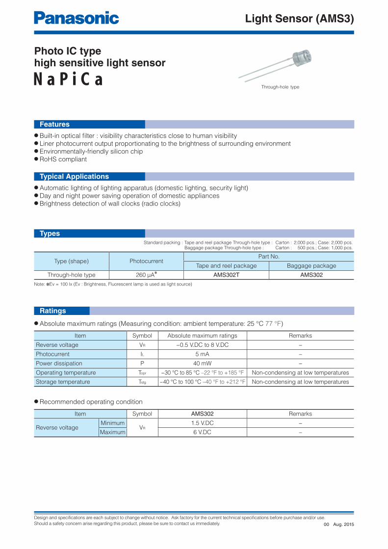
Through-hole type
Type (shape) PhotocurrentPart No.
Tape and reel package Baggage package
Through-hole type 260 μA✽ AMS302T AMS302
Item Symbol Absolute maximum ratings Remarks
Reverse voltage VR −0.5 V.DC to 8 V.DC −
Photocurrent IL 5 mA −
Power dissipation P 40 mW −
Operating temperature Topr −30 °C to 85 °C –22 °F to +185 °F Non-condensing at low temperatures
Storage temperature Tstg −40 °C to 100 °C –40 °F to +212 °F Non-condensing at low temperatures
Item Symbol AMS302 Remarks
Reverse voltageMinimum
VR
1.5 V.DC −
Maximum 6 V.DC −
Note: ✽Ev = 100 lx (Ev : Brightness, Fluorescent lamp is used as light source)
Standard packing : Tape and reel package Through-hole type : Carton : 2,000 pcs.; Case: 2,000 pcs. Baggage package Through-hole type : Carton : 500 pcs.; Case: 1,000 pcs.
Aug. 201500

Design and specifications are each subject to change without notice. Ask factory for the current technical specifications before purchase and/or use.
Should a safety concern arise regarding this product, please be sure to contact us immediately.
Light Sensor (AMS3)
0 20 40 60 80 1000
10
15
5
20
25
30
35
40
45
50
Ambient temperature (°C)
AMS302
Pow
er
dis
sip
ation (
mW
)
10 100 1000010001
10
1
100
1000
10000
0.1
Brightness (lx)
AMS302
Photo
curr
ent (μ
A)
500 600 700 800 900 1000 11004003000
0.2
0.1
0.4
0.6
0.8
0.3
0.5
0.7
0.9
1.0
human visibilityAMS302
Wavelength (nm)
Rela
tive s
ensitiv
ity
0−20−40 20 40 60 80 100+32−4−40 +68 +104 +140 +176 +212
0.6
0.8
1.0
1.2
1.4
Ambient temperature (°C °F)
AMS302
Rela
tive p
hoto
curr
ent
40 60 1008020+104 +140 +212+176+68
0.01
0.1
1
10
0.001
0.0001
Ambient temperature (°C °F)
AMS302
Dark
curr
ent
(μA
)
320 1 4 5 6 7 80
0.2
0.4
0.6
0.8
1.0
1.2
Reverse voltage (V.DC)
AMS302
Rela
tive p
hoto
curr
ent
IF
VO
tftr
90 %
10 %
White LED
Cathode
Anode
VCC
AMS✽✽✽
IF
RL
VO
VRAMS302 : 2.5 V
● Electrical and optical characteristics (Measuring condition: ambient temperature: 25 °C 77 °F)
Item Symbol AMS302 Condition
Peak sensitivity wavelength − lp 580 nm −
Photocurrent 1
Minimum
IL1
9.1 μA
VR=5 V.DC, Ev=5 lx ✽1Typical 13 μA
Maximum 16.9 μA
Photocurrent 2
Minimum
IL2
182 μA
VR=5 V.DC, Ev=100 lx ✽2Typical 260 μA
Maximum 338 μA
Photocurrent 3 Typical IL3 500 μA VR=5 V.DC, Ev=100 lx ✽2
Dark current Maximum ID 0.3 μA VR=5 V.DC, Ev=0 lx
Switching
time
Rise time Typical tr 8.5 msVcc=5.0 V.DC, V0=2.5 V.DC, RL=5 kΩ
Fall time Typical tf 8.5 ms
Note : ✽1 Fluorescent lamp is used as light source. Ev = Brightness ✽2 CIE standard illuminant ‘A’ is used as light source.
[Measuring method for switching time]
1. Power dissipation vs. ambient temperature characteristics
4. Photocurrent vs. brightness characteristics Light source : Fluorescent lamp Reverse voltage : 5 V.DC Ambient temperature : 25 °C 77 °F
2. Relative sensitivity vs. wavelength characteristics Reverse voltage : 5 V.DC Ambient temperature : 25 °C 77 °F
5. Relative photocurrent vs. ambient temperature characteristics Light source : Fluorescent lamp, Brightness : 100 lx Reverse voltage : 5 V.DC
3. Dark current vs. ambient temperature characteristics Reverse voltage : 5 V.DC
5. Relative photocurrent vs. reverse voltage characteristics Light source : Fluorescent lamp, Brightness : 100 lx Ambient temperature : 25 °C 77 °F
Reference Data
Aug. 201500

Design and specifications are each subject to change without notice. Ask factory for the current technical specifications before purchase and/or use.
Should a safety concern arise regarding this product, please be sure to contact us immediately.
Light Sensor (AMS3)
1001010.1 10000.1
1
10
100
Resistive load (kΩ)
AMS302 trAMS302 tf
Sw
itc
hin
g tim
e (
ms)
1 AMP 2
2Cathode
1Anode
− +
4.3
±0
.2
(2.54)
(0.100)
(1.0
)
0.16
9±0.
008
(0.0
39
)
2-□0.5
2-□0.020
34
±3
1.3
39
±0
.11
8
Ma
x.1
.5
(2.5
)
(0.0
98)
Max. 1.0Max.0.039
9.1
(1.0
)
(.0
39
)
(0.1
7)
(0.0
07
)
1.0
Max
.0.0
59
0.3
58
0.0
39
21
1 Anode : −2 Cathode : +
DETECTION AREA
5.0±0.2 dia.0.197±.008 dia.
5.8 dia.0.228 dia.
7. Switching time vs. resistive load characteristics Light source : White LED Power voltage : 5 V.DC Resistive load voltage : 2.5 V.DC Ambient temperature : 25 °C 77 °F
Dimensions
The CAD data of the products with a mark can be downloaded from: http://industrial.panasonic.com/
General tolerance : ±0.5 ±0.020
unit : mm inch
Safety PrecautionsFollow the instructions to prevent injuries and accidents. • Avoid use beyond the specifications. Such use may generate abnormal heat, smoke and fire.
• Correctly connect terminals according to the pin arrangement in the specifications. Misconnection may invite unexpected malfunction, abnormal heat, smoke and fire.
• For safety-sensitive use, arrange appropriate protective circuits and protection devices.
Aug. 201500

Design and specifications are each subject to change without notice. Ask factory for the current technical specifications before purchase and/or use.
Should a safety concern arise regarding this product, please be sure to contact us immediately.
Light Sensor (AMS3)
T1
T2
t1t2 t3
CAUTIONS FOR USE
■ Applying stress beyond absolute maximum rating
When voltage and current values of each terminal exceed absolute maximum rating, overvoltage and overcurrent may deteriorate the internal element. In extreme cases, such excess may melt wires or damage the silicon P/N junction. Design the product not to exceed the absolute maximum rating even momentarily.
■ Deterioration and damage by static electricity discharge
The phenomenon, deteriorating the internal element, is generally called electrostatic breakdown. It is caused by discharge of static electricity, arisen from multiple factors, to each terminal. Once unpacked, perform antistatic countermeasures and follow the instructions below.
1) Operators must wear antistatic cloths and human body grounding devices, and have the protective resistance of between 500 kΩ and 1 MΩ.
2) Cover the surface of workbench by electro-conductive metal plates and ground measuring instruments and jigs.
3) Use the soldering iron which has a small leakage current or ground the soldering tip. (The soldering iron for a low voltage is recommended)
4) Ground the assembling equipment.5) When packing printed-circuit boards and
devices, avoid polymeric materials, which have electrification characteristics, such as expanded polystyrene and plastic.
6) When storing and transporting the sensor, choose the environment where static electricity is hardly generated (e.g., humidity between 45 and 60 %) and protect the product by using electroconductive packaging materials.
■ When the power is supplied, the current fl owing into the
sensor varies in order to stabilize the internal circuit.
■ Storage
The sensor is in the transparent resin package. Due to its sensitivity to humidity, the package is moisture-proof. When storing the sensor, follow the instructions below.
1) Promptly use after opening. (within a week, below 30 °C 86 °F/60 % R.H.)
2) Once unpacked, preserving in a moisture-proof manner, such as keeping in a moisture-proof bag with silica gels, is recommended for long-term storage. (use within 3 months)
3) Ext remely bad storage condi t ions may deteriorate solderability or characteristics, and defect the appearance. Recommended conditions of the storage place are below. • Temperature : 0 to 30 °C 32 to 86 °F• Humidity : Below 60% R.H. (Avoid freezing
and dew condensation)• Atmosphere: Low-dust and free from noxious
chemicals such as sulfurous acid gas✽ During soldering, when adding thermal stress
in a moisture absorbing state, moisture evaporates, swells and generates stress to the internal package. To avoid swellings and cracks in the surface of the package, follow soldering conditions below.
■ Recommended soldering conditions<Through-hole type>
1) Recommended conditions(1) Double-wave soldering method
T1 = 120 °C 248 °FT2 = Below 260 °C 500 °Ft2 = Less than 120 sec.t2+t3 = Less than 6 sec.
(2) Soldering method Tip temperature : 350 to 400 °C 662 to 752 °F Wattage : 30 to 60 W Soldering time : Less than 3 sec.
2) Keep the soldering part at a distance of 3 mm 0.118 inch or more from the root of the lead.
■ Mounting1) When various packages are on one circuit board,
temperature rise of the lead largely depends on the package size. Keep temperature of the soldered terminals of the products below the previously mentioned specifications. Before use, check the performance with actual equipment.
2) I f mount ing condi t ions are beyond the specifications above, such use may decrease the resin strength, increase mismatching in the thermal expansion coefficient of each component material, generate cracks in the package and break the bonding wire. Please consult us before use.
■ CleaningFor flux cleaning, immersion cleaning by ASAHIKLIN AK-225 is recommended. If using ultrasonic cleaning for unavoidable reasons, implementation conditions should not be beyond the specifications below. Before use, check and ensure that there is no defect.
• Frequency : 27 to 29 kHz • Ultrasonic outlet : Below 0.25W/cm2 ✽
• Cleaning time : Less than 30 sec. • Cleaning solvent : ASAHIKLIN AK-225 • Others : In order to prevent the
printedcircuit board and elements from contacting with ultrasonic oscillator, clean the flux while the sensor is suspended in the solution.
✽ Ultrasonic outlet per unit area (bottom area) of cleaning tank
■ TransportationExcessive vibration during transport may deform the lead or damage the sensor. Carefully handle the exterior and interior boxes.
■ Avoid use in the highly-humid or dusty environment, the corrosive gas, an environment where organic solvent can be adhered.
■ Lead-forming and cuttings1) Before soldering, perform lead forming at
normal temperature.2) When forming or cutting the lead, keep the spot at
a distance of 3 mm 0.118 inch or more from the root of the lead.
3) When forming and cutting, fix the root of the lead.4) Avoid mounting which may cause stress on the
root of the lead.
Aug. 201500

Design and specifications are each subject to change without notice. Ask factory for the current technical specifications before purchase and/or use.
Should a safety concern arise regarding this product, please be sure to contact us immediately.
Light Sensor (AMS3)
D0
Δp Δh
H
L
F
P2 P
P0
W
W W0
W2
1
Anode side Cathode side
Note : Zigzag tape style is used.
● The following shows the packaging format
Through-hole type tape and reel (mm inch)
Type Tape dimensions
Light sensor
NaPiCa
Through-hole type
AMS302T
Term Symbol Explanation
Reverse voltage VR The applied voltage between the cathode and anode.
Photocurrent IL The current that fl ows between the cathode and anode when light is applied.
Power dissipation P The electric power loss that occurs between the cathode and anode.
Operating temperature ToprThe workable ambient temperature range at which normal operation is possible
under the condition of a prescribed allowable loss.
Storage temperature TstgThe ambient temperature range at which the sensor can be left or stored without
applying voltage.
Peak sensitivity wavelength lp The wavelength of light at which sensitivity is at its maximum.
Dark current IDThe current between the cathode and anode when reverse voltage is applied during
darkness.
Rise time tr Time required for the output waveform to rise from 10 % to 90 % when light is applied.
Fall time tf Time required for the output waveform to fall from 90 % to 10 % when light is cut.
Light Sensor NaPiCa terminology
Item Symbol Dimensions Remarks
Feed hole pitch
P012.7±0.30.500±0.012
Product interval pitch
P12.7±1.00.500±0.039
Product distance
P26.35±1.30.250±0.051
Product bottomdistance
H20.5±1.00.807±0.039
Lead interval F2.54±0.50.100±0.020
Product slant Δh0±1.0
0±0.039
Product tilt Δp0±1.0
0±0.039
Tape width W18.0+1.0
0.709+0.039
Holding tape width
W013.0±0.30.512±0.012
Feed hole position
W19.0+0.75
0.354+0.030
Holding tape distance
W20 to 0.5
0 to 0.020
Feed hole diameter
D03.8±0.2
0.150±0.008
Tape thickness
t0.5±0.20.020±0.008
Included holdingtape thickness
Defective productcutoff position
LMax:11.0Max:0.433
−0.5
−0.020
−0.020
−0.50
Aug. 201500
Design and specifications are each subject to change without notice. Ask factory for the current technical specifications before purchase and/or use.
Should a safety concern arise regarding this product, please be sure to contact us immediately.
MA Motion Sensor (AMA1, AMBA1, 2, 3)
:::
Detection distance type (shape)
Short typeMiddle typeLong type
123
:::
Classification by output method & mounting direction
NPN open collector/H typeNPN open collector/V typePNP open collector/V type
056
:
:
Operating voltageFree-ranging power type (5.5 V.DC to 27 V.DC)5V.DC type(4.5 V.DC to 5.5 V.DC)
2
9
:
:
Triggering functionExternal triggering typeBuilt-in oscillation circuit type (Internal trigger)
1
4
:A
:BA
AM
Thin short type MA Motion sensorMA Motion sensor
Rated detection distance
Active infrared(area refl ective)human detection sensorMA MOTION SENSOR
● Reliable detection hardly infl uenced by refl ectivity of targeted objects● Ready-to-use with DC power source (built-in oscillation circuit type)● Capability to adjoin sensors● RoHS compliant
● Equipment around water: automatic lighting of wash-units, toilets, automatic fl ush● Stores and fi nancial markets: automatic doors, lighting, ATM, visitor sensors● Amusement equipment: seating detection for pachinko machines, game displays● Medical equipment markets: noncontact switches
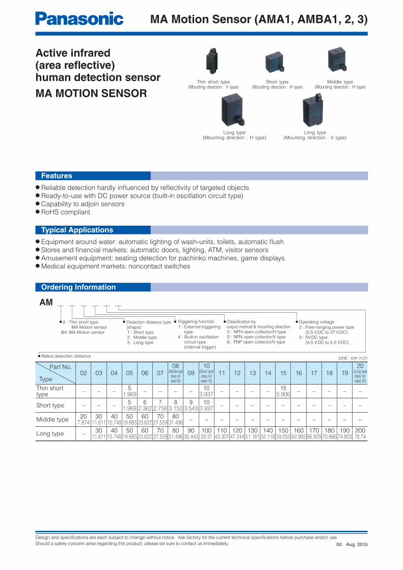
Thin short type(Mounting direction : V type)
Part No.
Type02 03 04 05 06 07
08(Middle type
does notneed 08)
0910
(Short typedoes notneed 10)
11 12 13 14 15 16 17 18 1920
(Long typedoes notneed 20)
Thin short type
– – –5
1.969– – – –
103.937
– – – –15
5.906– – – – –
Short type – – –5
1.9696
2.3627
2.7568
3.1509
3.54310
3.937– – – – – – – – – –
Middle type20
7.87430
11.81140
15.74850
19.68560
23.62270
27.55980
31.496– – – – – – – – – – – –
Long type –30
11.81140
15.74850
19.68560
23.62270
27.55980
31.49690
35.44310039.37
11043.307
12047.244
13051.181
14055.118
15059.055
16062.992
17066.929
18070.866
19074.803
20078.74
Short type(Mounting direction : H type)
Long type(Mounting direction : H type)
Long type(Mounting direction : V type)
Middle type(Mounting direction : H type)
Features
Typical Applications
Ordering Information
Unit : cm inch
Aug. 201500

Design and specifications are each subject to change without notice. Ask factory for the current technical specifications before purchase and/or use.
Should a safety concern arise regarding this product, please be sure to contact us immediately.
MA Motion Sensor (AMA1, AMBA1, 2, 3)
● Detection distance type (distance limited) 1) Thin short type (V type)
Operating voltage Output methodRated detection
distance
Built-in oscillation circuit type External triggering type
Part No. Part No.
4.5 V.DC to 5.5 V.DC
NPN open
collector output
5 cm 1.969 inch AMA145905 AMA115905
10 cm 3.937 inch AMA1459 AMA1159
15 cm 5.906 inch AMA145915 AMA115915
PNP open
collector output
5 cm 1.969 inch AMA146905 AMA116905
10 cm 3.937 inch AMA1469 AMA1169
15 cm 5.906 inch AMA146915 AMA116915
Note: If using multiple sensors adjacently or reducing power consumption, contact us for the optimal external trigger type.
2) Short type (H type)
3) Middle type (H type)
Rated operatingvoltage
Rated detectiondistance
Mounting direction : H type
Short type
Built-in oscillation circuit type External triggering type
Part No. Part No.
4.5 V.DC to 5.5 V.DC
5 cm 1.969 inch AMBA140905 AMBA110905
6 cm 2.362 inch AMBA140906 AMBA110906
7 cm 2.756 inch AMBA140907 AMBA110907
8 cm 3.150 inch AMBA140908 AMBA110908
9 cm 3.543 inch AMBA140909 AMBA110909
10 cm 3.937 inch AMBA1409 AMBA1109
5.5 V.DC to 27 V.DC
5 cm 1.969 inch AMBA140205 AMBA110205
6 cm 2.362 inch AMBA140206 AMBA110206
7 cm 2.756 inch AMBA140207 AMBA110207
8 cm 3.150 inch AMBA140208 AMBA110208
9 cm 3.543 inch AMBA140209 AMBA110209
10 cm 3.937 inch AMBA1402 AMBA1102
Rated operatingvoltage
Rated detectiondistance
Mounting direction : H type
Middle type
Built-in oscillation circuit type External triggering type
Part No. Part No.
4.5 V.DC to 5.5 V.DC
20 cm 7.874 inch AMBA240902 AMBA210902
30 cm 11.811 inch AMBA240903 AMBA210903
40 cm 15.748 inch AMBA240904 AMBA210904
50 cm 19.685 inch AMBA240905 AMBA210905
60 cm 23.622 inch AMBA240906 AMBA210906
70 cm 27.559 inch AMBA240907 AMBA210907
80 cm 31.496 inch AMBA2409 AMBA2109
5.5 V.DC to 27 V.DC
20 cm 7.874 inch AMBA240202 AMBA210202
30 cm 11.811 inch AMBA240203 AMBA210203
40 cm 15.748 inch AMBA240204 AMBA210204
50 cm 19.685 inch AMBA240205 AMBA210205
60 cm 23.622 inch AMBA240206 AMBA210206
70 cm 27.559 inch AMBA240207 AMBA210207
80 cm 31.496 inch AMBA2402 AMBA2102
Note: If using multiple sensors adjacently or reducing power consumption, contact us for the optimal external trigger type.
Standard packing: Carton: 20 pcs.; Case: 200 pcs.
Standard packing: Carton: 20 pcs.; Case: 200 pcs.
Standard packing: Carton: 20 pcs.; Case: 200 pcs.
Note: If using multiple sensors adjacently or reducing power consumption, contact us for the optimal external trigger type.
Product Types
Aug. 201500
Design and specifications are each subject to change without notice. Ask factory for the current technical specifications before purchase and/or use.
Should a safety concern arise regarding this product, please be sure to contact us immediately.
MA Motion Sensor (AMA1, AMBA1, 2, 3)
4) Long type
Rated operatingvoltage
Rated detectiondistance
Mounting direction : H type Mounting direction: V type
Long type
Built-in oscillation circuit type
External triggering type
Built-in oscillation circuit type
External triggering type
Part No. Part No. Part No. Part No.
4.5 V.DC to 5.5 V.DC
30 cm 11.811 inch AMBA340903 AMBA310903 AMBA345903 AMBA315903
40 cm 15.748 inch AMBA340904 AMBA310904 AMBA345904 AMBA315904
50 cm 19.685 inch AMBA340905 AMBA310905 AMBA345905 AMBA315905
60 cm 23.622 inch AMBA340906 AMBA310906 AMBA345906 AMBA315906
70 cm 27.559 inch AMBA340907 AMBA310907 AMBA345907 AMBA315907
80 cm 31.496 inch AMBA340908 AMBA310908 AMBA345908 AMBA315908
90 cm 35.433 inch AMBA340909 AMBA310909 AMBA345909 AMBA315909
100 cm 39.370 inch AMBA340910 AMBA310910 AMBA345910 AMBA315910
110 cm 43.307 inch AMBA340911 AMBA310911 AMBA345911 AMBA315911
120 cm 47.244 inch AMBA340912 AMBA310912 AMBA345912 AMBA315912
130 cm 51.181 inch AMBA340913 AMBA310913 AMBA345913 AMBA315913
140 cm 55.118 inch AMBA340914 AMBA310914 AMBA345914 AMBA315914
150 cm 59.055 inch AMBA340915 AMBA310915 AMBA345915 AMBA315915
160 cm 62.992 inch AMBA340916 AMBA310916 AMBA345916 AMBA315916
170 cm 66.929 inch AMBA340917 AMBA310917 AMBA345917 AMBA315917
180 cm 70.866 inch AMBA340918 AMBA310918 AMBA345918 AMBA315918
190 cm 74.803 inch AMBA340919 AMBA310919 AMBA345919 AMBA315919
200 cm 78.740 inch AMBA3409 AMBA3109 AMBA3459 AMBA3159
5.5 V.DC to 27 V.DC
30 cm 11.811 inch AMBA340203 AMBA310203 AMBA345203 AMBA315203
40 cm 15.748 inch AMBA340204 AMBA310204 AMBA345204 AMBA315204
50 cm 19.685 inch AMBA340205 AMBA310205 AMBA345205 AMBA315205
60 cm 23.622 inch AMBA340206 AMBA310206 AMBA345206 AMBA315206
70 cm 27.559 inch AMBA340207 AMBA310207 AMBA345207 AMBA315207
80 cm 31.496 inch AMBA340208 AMBA310208 AMBA345208 AMBA315208
90 cm 35.433 inch AMBA340209 AMBA310209 AMBA345209 AMBA315209
100 cm 39.370 inch AMBA340210 AMBA310210 AMBA345210 AMBA315210
110 cm 43.307 inch AMBA340211 AMBA310211 AMBA345211 AMBA315211
120 cm 47.244 inch AMBA340212 AMBA310212 AMBA345212 AMBA315212
130 cm 51.181 inch AMBA340213 AMBA310213 AMBA345213 AMBA315213
140 cm 55.118 inch AMBA340214 AMBA310214 AMBA345214 AMBA315214
150 cm 59.055 inch AMBA340215 AMBA310215 AMBA345215 AMBA315215
160 cm 62.992 inch AMBA340216 AMBA310216 AMBA345216 AMBA315216
170 cm 66.929 inch AMBA340217 AMBA310217 AMBA345217 AMBA315217
180 cm 70.866 inch AMBA340218 AMBA310218 AMBA345218 AMBA315218
190 cm 74.803 inch AMBA340219 AMBA310219 AMBA345219 AMBA315219
200 cm 78.740 inch AMBA3402 AMBA3102 AMBA3452 AMBA3152
Note: If using multiple sensors adjacently or reducing power consumption, contact us for the optimal external trigger type.
Notes : ✽1. Ambient brightness: 500 lx ✽2. Prevent direct light (within 30 ° against the optical axis of the sensor) from entering into the sensor.
● Detection performance 1) Thin short type (Measuring conditions: ambient temp. : 25 °C 77 °F; operating voltage : 5 V.DC)
ItemsUnit Thin short type Measured
conditionscm inch 5 1.969 10 3.937 15 3.937
Rated detection distance
Minimum
mm inch
45 1.772 90 3.543 135 5.315with a standard
refl ection board ✽1Typical 50 1.969 100 3.937 150 5.906
Maximum 55 2.165 110 4.331 165 6.496
Measuring tolerance Typical % 10 25 35 Refl ection rate: 90 % to 18 %
Usable ambientbrightness (Resistance to ambient light) ✽2
Brightness of sensor surface
Maximum
lx
30,000See the drawing (Fig. 1) on the Brightness next page.Brightness of
refl ection surfaceMaximum 24,000
Rating
Standard packing: Carton: 20 pcs.; Case: 200 pcs.
Aug. 201500

Design and specifications are each subject to change without notice. Ask factory for the current technical specifications before purchase and/or use.
Should a safety concern arise regarding this product, please be sure to contact us immediately.
MA Motion Sensor (AMA1, AMBA1, 2, 3)
Notes : ✽1. After the order receipt, the average rated detecting distance can be increased to max 15 cm 5.906 inch. Please consult us. ✽2. Prevent direct light (within 30 ° against the optical axis of the sensor) from entering into the sensor.
Notes : ✽1. After the order receipt, the average rated detecting distance can be increased to max 110 cm 43.307 inch. Please consult us. ✽2. Prevent direct light (within 30 ° against the optical axis of the sensor) from entering into the sensor.
Notes : ✽ Prevent direct light (within 30 ° against the optical axis of the sensor) from entering into the sensor.
2) Short type (Measuring conditions : ambient temp.: 25 °C 77 °F; operating voltage: 5 V.DC type 5 V.DC, Free-ranging power type 24 V.DC)
3) Middle type (Measuring conditions: ambient temp.: 25 °C 77 °F; operating voltage: 5 V.DC type 5 V.DC, Free-ranging power type 24 V.DC)
4) Long type (Measuring conditions: ambient temp.: 25 °C 77 °F; operating voltage: 5 V.DC type 5 V.DC, Free-ranging power type 24 V.DC)
ItemsUnit Short type ✽1
Measuredconditionscm
inch 5
1.969 6
2.362 7
2.756 8
3.150 9
3.54310
3.937
Rated detection distance
Minimum
mminch
451.772
542.126
63 2.480
722.835
81 3.189
903.543
with a standardrefl ection board
Typical50
1.96960
2.36270
2.75680
3.15090
3.543100
3.937
Maximum55
2.16566
2.59877
3.03188
3.46599
3.898110
4.331
Measuring tolerance Typical % 10 15 20 25 Refl ection rate: 90 % to 18 %
Usable ambientbrightness (Resistance to ambient light) ✽2
Brightness of sensor surface
Maximumlx
30,000 See the drawing (Fig. 1) on the next page.Brightness of
refl ection surfaceMaximum 24,000
ItemsUnit Middle type ✽1
Measuredconditionscm
inch 20
7.87430
11.81140
15.74850
19.68560
23.62270
27.55980
31.496
Rated detection distance
Minimum
mminch
1907.480
28511.220
38014.961
47518.701
57022.441
66526.181
76029.921
with a standardrefl ection board
Typical200
7.874300
11.811400
15.748500
19.685600
23.622700
27.559800
31.496
Maximum210
8.268315
12.402420
16.535525
20.669630
24.803735
28.937840
33.071
Measuring tolerance Typical % 3 5 10 Refl ection rate: 90 % to 18 %
Usable ambientbrightness (Resistance to ambient light) ✽2
Brightness of sensor surface
Maximumlx
30,000 See the drawing (Fig. 1) on the next page.Brightness of
refl ection surfaceMaximum 24,000
ItemsUnit Long type
Measuredconditionscm
inch30
11.81140
15.74850
19.68560
23.62270
27.55980
31.49690
34.433100
39.370110
43.307
Rated detection distance
Minimum
mminch
28511.220
38014.961
47518.701
57022.441
66526.181
76029.921
85533.661
95037.402
104541.142
with a standardrefl ection board
Typical300
11.811400
15.748500
19.685600
23.622700
27.559800
31.496900
34.433100039.370
110043.307
Maximum315
12.402420
16.535525
20.669630
24.803735
28.937840
33.071945
37.205105041.339
115545.472
Measuring tolerance Typical % 3 5 Refl ection rate: 90 % to 18 %
Usable ambientbrightness (Resistance to ambient light) ✽
Brightness of sensor surface
Maximumlx
30,000 See the drawing (Fig. 1) on the next page.Brightness of
refl ection surfaceMaximum 24,000
ItemsUnit Long type
Measuredconditionscm
inch120
47.244130
51.181140
55.118150
59.055160
62.992170
66.929180
70.866190
74.803200
78.740
Rated detection distance
Minimum
mminch
114044.882
123548.622
133052.362
142556.102
152059.842
161563.583
171067.323
180571.063
190074.803
with a standardrefl ection board
Typical120047.244
130051.181
140055.118
150059.055
160062.992
170066.929
180070.866
190074.803
200078.740
Maximum126049.606
136553.740
147057.874
157562.008
168066.142
178570.275
189074.409
199578.543
210082.677
Measuring tolerance Typical % 5 10 15 Refl ection rate: 90 % to 18 %
Usable ambientbrightness (Resistance to ambient light) ✽
Brightness of sensor surface
Maximumlx
30,000 See the drawing (Fig. 1) on the next page.Brightness of
refl ection surfaceMaximum 24,000
Aug. 201500

Design and specifications are each subject to change without notice. Ask factory for the current technical specifications before purchase and/or use.
Should a safety concern arise regarding this product, please be sure to contact us immediately.
MA Motion Sensor (AMA1, AMBA1, 2, 3)
Light meter
Sensor
✽Area for prohibit
direct light
(q1, q1´)> 15 °
q1
q1´
30°
Light meter
Rated detection distance
Sensor
Reflection
board
q2
30 ° < (q2, q2´) < 45 °
q2´
Items
Items
Absolute maximum rating
Built-in oscillation circuit type External triggering type
5 V.DC type Free-ranging power type 5 V.DC type Free-ranging power type
Power supply voltage −0.3 V.DC to 6 V.DC −0.3 V.DC to 30 V.DC −0.3 V.DC to 6 V.DC −0.3 V.DC to 30 V.DC
Output dielectric strength 30 V.DC 30 V.DC
Output fl ow current 100 mA 10 mA✽
Usable ambient temperature –25 °C to +75 °C +5 °F to +131 °F (No freezing) –25 °C to +75 °C +5 °F to +131 °F (No freezing)
Storage temperature –30 °C to +85 °C –4 °F to +176 °F –30 °C to +85 °C –4 °F to +176 °F
Items Symbol
Thin short type✽
Short type Middle type Long typeMeasuredconditionsNPN
output typePNP
output type
Rated operating voltage
Minimum
VDD
5 V.DC type : 4.5V.DC / Free-ranging power type : 5.5 V.DC
Typical –
Maximum 5 V.DC type : 5.5 V.DC /Free-ranging power type : 27 V.DC
Average currentconsumption(Iout=0 mA)
No detection
Minimum
It
–
Typical 4.5 mA5 V.DC type : 4.5 mA
Free-ranging power type : 5.6 mA
Maximum 6.2 mA5 V.DC type : 6.2 mA
Free-ranging power type : 7.8 mA
Detection
Minimum
It
–
Typical 7.0 mA 11.0 mA5 V.DC type : 7.0 mA
Free-ranging power type : 9.1 mA
Maximum 11.2 mA 15.2 mA5 V.DC type : 11.2 mA
Free-ranging power type : 14.2 mA
Measuring cycle Typical T 8 ms/cycle
Outputcharacteristics
Remain voltage Maximum Vr 1 V.DC 1.2 V.DC 1 V.DC It=100 mA
Leakage current Maximum II 5 μA 3 μA V=30 V.DC
● Measuring condition: ambient temp.: 25 °C 77 °F
● Measuring conditions : ambient temp.: 25 °C 77 °F; operating voltage: 5 V.DC type 5 V.DC, free-ranging power type 24 V.DC) 1) Built-in oscillation circuit type
Notes : ✽ Thin short type is only: 100 mA
Notes : ✽ The thin short type is only available for 5 V.DC.
• For thin short type: Standard reflection board : 150 mm 5.906 inch square area,
90% reflection rate.• For short type: Standard reflection board: 100 mm 3.937 inch square area,
90% reflection rate.• For middle type: Standard reflection board: 200 mm 7.874 inch square area,
90% reflection rate.• For long type: Standard reflection board: 500 mm 19.685 inch square area,
90% reflection rate.
<Fig. 1>[Brightness of sensor surface]
Notes : 1. Detecting an object within the maximum preset detection distance.
2. Distance deviation = a–ba × 100 (%)
a: detection distance of detection target with reflectance of 90 %. b: detection distance of standard detection target with reflectance of 18 %.
Notes : If sunlight or strobe/inverter light (including the regular refl ection light from glasses and mirrors) directly enters from the inhibition area, those lights may cause malfunction of the sensor.sensor) from entering into the sensor.
[Brightness of reflection surface]
Electrical characteristics
Absolute maximum rating
( )
Aug. 201500

Design and specifications are each subject to change without notice. Ask factory for the current technical specifications before purchase and/or use.
Should a safety concern arise regarding this product, please be sure to contact us immediately.
MA Motion Sensor (AMA1, AMBA1, 2, 3)
Stand by
2 ms(approx.)
Operation
OFF
(With trigger input) (With trigger input) (With trigger input) (With trigger input)
Non-detection statusinput
(The output is latched
by the previous trigger.)
(The output is latched
by the previous trigger.)
Detection status
OFF
ON
Internal sensoroperation
Trigger input
Output transistor
✤a ✤b ✤c
2 ms(approx.)
2 ms(approx.)
2 ms(approx.)
✤d
ON
OFF
OFF
ON
Power supply
Non-detection
status
Circuit
stability
time
Non-detection
status
Detection
status
Non-detection
status
Circuit
stability
time
Non-detection
status
Detection
status
(NPN output types of the AMA series and all of AMBA series)
ON
OFF
ON
OFF
(PNP output types of the AMA series)
Output transistor
(open collector)
Power supply
Output transistor
(open collector)
(NPN output types of the AMA series and all of AMBA series)
(PNP output types of the AMA series)
GND
Outputtransistor
Output
GND
Detection status:
output transistor ON
Non-detection status:
output transistor OFF
Detection status:
output transistor ON
Non-detection status:
output transistor OFF
GND
Outputtransistor Output
Items SymbolThin short type✽1
Short type Middle type Long typeMeasuredconditionsNPN
output typePNP
output type
Rated operating voltage
Minimum
VDD
5 V.DC type : 4.5 V.DC / Free-ranging power type : 5.5 V.DC
Typical –
Maximum 5 V.DC type : 5.5 V.DC/Free-ranging type : 27 V.DC
Average currentconsumption
Withouttrigger input
Output OFF
Minimum
Ib
–
✽2 ✤bTypical 0.1 mA 5 V.DC type: 0.1 mA/Free-ranging type: 1.0 mA
Maximum 0.3 mA 5 V.DC type: 0.3 mA/Free-ranging type: 1.8 mA
Output ON
Minimum
Id
–
✽2 ✤dTypical 2.6 mA 6.7 mA 5 V.DC type: 0.5 mA/Free-ranging type: 1.4 mA
Maximum 6.6 mA 9.6 mA 5 V.DC type: 3.4 mA/Free-ranging type: 4.5 mA
With triggerinput
Output OFF
Minimum
Ia
–
✽2 ✤aTypical 2.2 mA 5 V.DC type: 2.2 mA/Free-ranging type: 3.1 mA
Maximum 6.2 mA 5 V.DC type: 6.2 mA/Free-ranging type: 7.2 mA
Output ON
Minimum
Ic
–
✽2 ✤cTypical 4.2 mA 8.5 mA 5 V.DC type: 2.4 mA/Free-ranging type: 3.3 mA
Maximum 8.2 mA 12.5 mA 5 V.DC type: 8.2 mA/Free-ranging type: 9.3 mA
Measuring cycle (Trigger interval) Typical Tt 5 ms/cycle
External trigger
Pulse widthMinimum
Tw20 μs
Maximum 1/2 TtHalf off the distance period
LevelMinimum VTL 0.8 V
Maximum VTH 3 V ✽3Response performance:time from trigger pulse fall to detection output
Typical Tr 5 ms
Outputcharacteristics
Remain voltage Minimum Vr 1 V.DC 1.2 V.DC 1 V.DC It=10 mA
Leakage current Maximum II 5 μA 3 μA V=30 V.DC
2) External triggering type (trigger conditions: trigger pulse width = 20 μs and trigger synchronization = 5 ms)
Notes : ✽1. The thin short type is only available for 5 V.DC. ✽2. The ratio between the 4 operating modes (✤a to ✤d) depends
on the external trigger period and detector time, and the current consumption corresponds with this varying ratio.
✽3. A high level is established in the open state due to pull-up by the internal circuit. (Refer to the connector wiring diagram.)
Notes : ✽1. Circuit stability time : Max. 12 ms ✽2. During the time taken for the circuit to stabilize after the power is turned on, the ON/OFF status of the output transistor is not determined by
whether the sensor is in the detection status or non-detection status.
✽4. The output transistor is open collector. The output transistor is turned ON by the sensor detection
status and turned OFF by its non-detection status.
● Built-in oscillation circuit type
Timing Chart
Aug. 201500

Design and specifications are each subject to change without notice. Ask factory for the current technical specifications before purchase and/or use.
Should a safety concern arise regarding this product, please be sure to contact us immediately.
MA Motion Sensor (AMA1, AMBA1, 2, 3)
VTH
VTL
OFF
OFF
ON
External trigger
ONPower supply
ON
OFF
Output transistor
Output transistor(open collector)
NPN output types
of the AMA series
AMBA series
PNP output types
of the AMA series
Non-detection
status
Circuit
stability
time
Non-detection
status
Detection
status
Non-detection
status
Circuit
stability
time
Non-detection
status
Detection
status
VTH
VTL
Output
External trigger
Tt : Min. 5 ms
Change
(ON to OFF or
OFF to ON)
Tr : Max. 5 ms
Tw
Power supply
Min.33 μF✽3
Output
✽1
++
2
N.C. (No connection)
4
Tr1
3
GND
Power supply
Output
✽1
++
2
4
Tr1
3
GND
Min.33 μF✽3
N.C. (No connection)
Power supply
Output
2
External trigger
input4
1
3
GND
✽1
✽2
✽3
++ Min.
33 μF
2
1
3
GND
✽1
✽2
++
4
✽3
Power supply
OutputExternal trigger
input
Min.33 μF
● External triggering type
Notes: ✽1. The output transistor has an open collector structure. • Detection status: Output transistor ON (connected to GND) • Non-detection status: Output transistor OFF (open state) ✽2. The status of the external trigger input is as follows: • Open at the high level • GND (less than 0.8 V) at the low level Do not apply a high voltage. ✽3. Install capacitor (of 33 μF or over) on the power input terminal of the sensor in order to secure power superimposed noise resistance and
stabilize the power supply voltage.
Notes : The sensor recognizes at the VTH → VTL edge of an external trigger that the external trigger has been input.
● Wiring diagram of connector
Built-in oscillation circuit type External triggering type
NPN
output type
PNP
output type
Notes : ✽1. Circuit stability time: Max. 12 ms ✽2. During the time taken for the circuit to stabilize after the
power is turned on, the ON/OFF status of the output transistor is not determined by whether the sensor is in the detection status or non-detection status.is not determined by whether the sensor is in the detection status or non-detection status.
How To Use
Aug. 201500

Design and specifications are each subject to change without notice. Ask factory for the current technical specifications before purchase and/or use.
Should a safety concern arise regarding this product, please be sure to contact us immediately.
MA Motion Sensor (AMA1, AMBA1, 2, 3)
Dete
ction d
ista
nce L
(m
m inch)
0
1003.937
100.394
200.787
301.181
401.575
501.969
602.362
702.756
803.150
903.543
Operating area within the dotted lines
Operating region for rated detection distance of 8 cm3.150 inch
Objects that enter the entire area are detected.
Operating area within the dotted lines
Object
Operating area within the solid lines
Object
Objects that even partially enter the area are detected.
Operating area within the solid lines
Note: If only part of the object is in the detection area, it is not
detected.
Detection width W (mm inch)
010
0.39410
0.394
200.787
200.787
Reflection board200 × 200 mm
7.874 × 7.874 inch(reflectivity: 90%)
9 cm 3.534 inch
8 cm 3.150 inch
7 cm 2.756 inch
6 cm 2.362 inch
5 cm 1.969 inchY
X
Reflection boardD
ete
ction d
ista
nce L
(m
m inch)
0
1003.937
100.394
200.787
301.181
401.575
501.969
602.362
702.756
803.150
903.543
Operating region for rated detection distance of 10 cm 3.937 inch
Detection width W (mm inch)
010
0.39410
0.394
200.787
200.787
0
2509.843
50019.685
75029.528
100039.37
125049.213
150059.055
175068.898
200078.74
Reflection board500 × 500 mm
19.685 × 19.685 inch(reflectivity: 90%)
150 cm59.055 inch
100 cm39.37 inch
50 cm19.685 inch
Y
X
Reflection board
301.181
401.575
401.575
Detection width W (mm inch)
Dete
ction d
ista
nce L
(m
m inch)
010
0.39410
0.39430
1.181
200.787
200.787
Operating region for rated detection distance of 200 cm 78.74 inch
0
1003.937
2007.874
30011.811
40015.748
50019.685
60023.622
70027.559
80031.496
Reflection board200 × 200 mm
7.874 × 7.874 inch(reflectivity: 90%)
70 cm27.559 inch
60 cm23.622 inch
50 cm19.685 inch
40 cm15.748 inch
30 cm11.811 inch
20 cm7.874 inch
Y
X
Reflection boardD
ete
ction d
ista
nce L
(m
m inch)
Operating region for rated detection distance of 80 cm 31.496 inch
301.181
401.575
401.575
Detection width W (mm inch)
010
0.39410
0.39430
1.181
200.787
200.787
2-R3.25
2-R0.128
29.0
20.01.142
0.787
11.0
10.0
0.433
0.394
Stamped side (one side only)
12.70.5006.6
0.260
Receiver
Projector
22
19.35
f3.1
31.2
5
14 23.1
29.50.4
Connector surface
(Front lens surface)
Optical surface
0.866
0.762
f0.122
1.228
0.197
0.551 0.909
1.1610.016
16f2.5
6.5
16.25
10
11
Receiver
Projector
Connector surface
(Front lens surface)
Optical surface
20
19.522.5
4
6
0.630f0.098
0.256
0.640
0.394
0.433
0.787
0.7680.886
0.157
0.236
● Operating region characteristics
● Thin short type (V type)
● Middle type (H type)
● Short type (H type)
How to interpret the graph Example: Operating area of the Short Type
with rated detection distance of 8 cm 3.150 inch.
1.-(1) Thin short type (AMA1□□□□□) Short type (AMBA1□□□□□)
1.-(2) Middle type (AMBA2□□□□□) 1.-(3) Long type (AMBA3□□□□□)
✽ Rear side connector protrusion: Max. 0.4mm
(Common to the Built-in oscillation circuit type and External triggering type)
Reference Data
Dimensions
The CAD data of the products with a mark can be downloaded from: http://industrial.panasonic.com/
unit : mm inch
Aug. 201500

Design and specifications are each subject to change without notice. Ask factory for the current technical specifications before purchase and/or use.
Should a safety concern arise regarding this product, please be sure to contact us immediately.
MA Motion Sensor (AMA1, AMBA1, 2, 3)
10
33f4.2
24.7
46
20
43
Receiver
Projector
7
29.7Max. 1
Connector surface
(Front lens surface)Optical surface
0.394
1.299f.165
0.972
1.811
0.787
1.693
0.276
1.1690.039
43
21
BM04B-SRSS(J.S.T. Mfg. Co., Ltd.)
1: Output2: GND3: Power source4. Built-in oscillation circuit type: N.C. External triggering type: external trigger input
4321
DF13-4P-1.25DSA(HIROSE ELECTRIC CO., LTD.)
4: Output3: GND2: Power source1. Built-in oscillation circuit type: N.C. External triggering type: external trigger input
4321
DF13-4P-1.25DS(HIROSE ELECTRIC CO., LTD.)
4: Output3: GND2: Power source1. Built-in oscillation circuit type: N.C. External triggering type: external trigger input
4321
DF13-4P-1.25DSA(HIROSE ELECTRIC CO., LTD.)
4: Output3: GND2: Power source1. Built-in oscillation circuit type: N.C. External triggering type: external trigger input
4321
DF13-4P-1.25DSA(HIROSE ELECTRIC CO., LTD.)
4: Output3: GND2: Power source1. Built-in oscillation circuit type: N.C. External triggering type: external trigger input
MAX. 1
29.7
7Optical surface Connector
surface10
20
Receiver
Projector
46
55
65
f4.2
0.039
1.169
0.2760.394
0.787
1.811
2.165
2.559
f0.165
The edge is soldered
4.5±1
150±5
4
Socket housing DF13-4S-1.25C
Lead wires AWG 28
(HIROSE ELECTRIC CO., LTD.)
6.65
0.177±.039
5.906±0.197
0.157
0.262
4. Output (Black)
3. GND (Blue)
2. Power source (Brown)
1. Built-in oscillation circuit type: N.C. External triggering type: external trigger input (Purple)
3. Power source (Brown)
2. GND (Blue)
4. Start signal input (Purple)
1. Output (Black)
Solder coated
Lead wires UL 10368, AWG 30
Socket housing SHR-04V-S
4.5±20.177±0.079
150±55.906±0.197
50.197
50.197
● Long type (H type)
● Thin short type (V type)
● Long type (H type)
● Connector with cable (for Short, Middle and Long type) AMV9003
● Connector with cable (for Thin short type)
AMV9002
● Short type (H type)
● Long type (V type)
● Middle type (H type)
● Long type (V type)
unit : mm inch
unit : mm inch
(Common to the Built-in oscillation circuit type and External triggering type)
Wiring Diagram (Connector Surface View)
Options
unit : mm inch
Aug. 201500
Design and specifications are each subject to change without notice. Ask factory for the current technical specifications before purchase and/or use.
Should a safety concern arise regarding this product, please be sure to contact us immediately.
MA Motion Sensor (AMA1, AMBA1, 2, 3)
Advancing direction
Y
X
Z
Advancing direction
Advancing direction
Object
Object
ObjectWhen advancing from the Y direction, the
detecting distance may become unstable.
Tolerance range
85
15
0 75−25+32 +167−13
Humidity (%RH)
(Avoid freezing when
used at temperatures
lower than 0 °C 32 °F)
(Avoidcondensationwhen used attemperatureshigher than 0 °C32 °F)
Temperature (°C, °F)
■ Use environment1) Avoid use in the steamy or dusty environment,
the corrosive gas, an environment where organic solvent can be adhered.
2) When using in a high-noise environment, perform countermeasures such as installing capacitor (of 33 μF or over) on the power input terminal of the sensor. Before use, check the performance under actual use conditions.
■ Wire connection1) Before the power is supplied, recheck wiring as
misconnection may damage the internal circuit. (ensure to avoid reverse connection)
2) Use wires shorter than 3 m 9.842 ft to protect the internal circuit. Before use, check under actual use conditions if there is no influence by surrounding environments.
3) Do not repeatedly attach/detach the connector.
■ Detecting part1) Keep the detecting surface clean. The detecting
surface is resistant to trash/ dust, however, if an excessive amount of trash/dust adhere to the surface, it may reduce the margin of detecting distance.
2) Dew condensation on the detecting surface may cause malfunction.
3) The sensor aims to detect human bodies. If the targeted object has extremely low reflectivity (e.g., objects frosted by black rubbers) or extremely high reflectivity (e.g., objects which regularly reflect: mirrors, glasses or glossy papers), the sensor may not be able to detect or the detecting distance may become unstable.
4) The front face of the lense and the case are polycarbonate-based. Generally they are stable against water, alcohol, oil, salt and weak acids. However, avoid alkalis, aromatic hydrocarbons and halogenated hydrocarbons as those substances may expand or melt the lense and the case.
5) If placing filters (covers) in front of the sensor and perform detection through the filters, following may occur: detection of the filters (covers), changes of the detecting distance or unstable operations.
6) If sensors are in facing positions, light from the opposing sensor may cause mutual interferences and malfunction. Before use, check the installation conditions.
7) When arranging multiple sensors in parallel, keep the interval of neighboring sensors as below or over. Before use, ensure that there is no mutual interference.
■ Recommended mounting directionAs below, install the sensor for the X and Z advancing directions of the targeted object.
For general precautions, see “General precautions for motion sensors” in the next page.
Part No. Sensor intervalAMBA1 series 5 cm 1.969 inchAMA1 series 8 cm 3.150 inchAMBA2 series 10 cm 3.937 inchAMBA3 series 20 cm 7.874 inch
NOTES
■ Ambient operating conditions1) Temperature: Refer to the absolute maximum ratings
for the temperature of each individual sensor.2) Humidity : 15 % to 85 % RH (No freezing nor condensation at low temperature)3) Atmospheric pressure: 86 to 106 kPa4) Because the humidity range differs depending
on the ambient temperature, the humidity range indicated below should be used. Continuous operation of the switch is possible within this range, but continuous use near the limit of the range should be avoided. This humidity range does not guarantee permanent performance.
<MA Motion Sensor>
In general, degradation of electronic devices accelerates when they are operated under conditions of high temperature or high humidity. Before use, confirm the reliability of the sensors under the expected operating conditions.
5) The sensors do not have a water-proof or dust-proof construction. Depending on the ambient operating conditions, some means of providing protection from water and dust and preventing the formation of ice and condensation must be provided prior to using the sensors. If a sensor is used with a cover installed, the initial detection performance specifications may not be able to be met. Confirm the operation under the actual operating conditions.
6) Take care to avoid exposing the sensors to heat, vibration or impact since malfunctioning may result.
■ Concerning external surge voltagesSince the internal circuitry may be destroyed if an external surge voltages is supplied, provide an element which will absorb the surges.
■ Concerning power supplysuperimposed noise1) Use a regulated power supply as the power
supply. Otherwise, power supplysuperimposed noise may cause the sensors to malfunction.
2) To maintain the power supply noise performance, be certain to connect a capacitor (33 μF or more) to the sensor power supply input terminal in order to stabilize the power supply voltage.
■ Drop damageIf the sensor is dropped, damage can occur resulting in incorrect operation. If dropped, be sure to do a visual check of the exterior for noticeable damage and check the operation characteristics for faulty operation.
■ Concerning the circuit sidesSince the circuit sides given in this catalog are not protected in terms of circuit design, check out the performance and reliability of the circuits prior to using the sensors.
Aug. 201500

Design and specifications are each subject to change without notice. Ask factory for the current technical specifications before purchase and/or use.
Should a safety concern arise regarding this product, please be sure to contact us immediately.
MA Motion Sensor (AMA1, AMBA1, 2, 3)
Head the following precautions to prevent injury
or accidents.
• Do not use these sensors under any circumstances in which the range of their ratings, environment conditions or other specifications are exceeded. Using the sensors in any way which causes their specifications to be exceeded may generate abnormally high levels of heat, emit smoke, etc., resulting in damage to the circuitry and possibly causing an accident.
• Before connecting a connector, check the pin layout by referring to the connector wiring diagram, specifications diagram, etc., and make sure that the connector is connected properly. Take note that mistakes made in connection may cause unforeseen problems in operation, generate abnormally high levels of heat, emit smoke, etc., resulting in damage to the circuitry.
• Do not use any motion sensor which has been disassembled or remodeled.
• Protection circuit recommended The possible failure mode is either open or short of the output transistor. An excess heat is the cause for short mode failure. For any important and serious application in terms of safety, add protection circuit or any other protection method.
Safety Precautions
Aug. 201500

Design and specifications are each subject to change without notice. Ask factory for the current technical specifications before purchase and/or use.
Should a safety concern arise regarding this product, please be sure to contact us immediately.
Infrared Array Sensor Grid-EYE (AMG88)
Vertical pixel Horizontal pixel8 pixels:8 8 pixels:8
Applied voltageHigh gainLow gain
::
12
::
Applied voltage3.3 V.DC5 V.DC
35
AMG 8 8
Infrared Array Sensor
Grid-EYE
● Temperature detection of two-dimensional area: 8 × 8 (64 pixels)● Digital output (capability of temperature value output)● Compact SMD package (adaptively to refl ow mounting)● RoHS compliant
High Precision Infrared Array Sensor based on Advanced MEMS Technology
● High function home appliances (microwaves and air-conditioners)● Energy saving at offi ce (air-conditioning/lighting control)● Digital signage● Automatic doors/elevators
Product name Number of pixel Operating voltage Amplifi cation factor Part number
Infrared array sensor
Grid-EYE
64
(Vertical 8 × Horizontal 8 Matrix)
3.3 V.DCHigh gain AMG8831
Low gain AMG8832
5.0 V.DCHigh gain AMG8851
Low gain AMG8852
ItemPerformance
High gain Low gain
Applied voltage 3.3 V.DC±0.3 V.DC or 5.0 V.DC±0.5 V.DC
Temperature range of measuring object 0 °C to 80 °C +32 °F to +176 °F −20 °C to 100 °C –4 °F to +212 °F
Operating temperature range 0 °C to 80 °C +32 °F to +176 °F −20 °C to 80 °C –4 °F to +176 °F
Storage temperature range −20 °C to 80 °C –4 °F to +176 °F −20 °C to 80 °C –4 °F to +176 °F
Features
Typical Applications
Ordering Information
Types
Rating
Tape and reel package : 1,000 pcs.
Aug. 201500

Design and specifications are each subject to change without notice. Ask factory for the current technical specifications before purchase and/or use.
Should a safety concern arise regarding this product, please be sure to contact us immediately.
Infrared Array Sensor Grid-EYE (AMG88)
Infrared array sensor3.3 V.DC or 5 V.DC
Selector
Thermistor
Gain
amp ADC
Control
ROM
SDA
SCL
AD_SELECT
INT
I2C I/F
Sensor chip
VDD
Capacitor
10 μF
GND
GND
9
6
2
3
5
4
Item Absolute maximum ratings Terminal
Applied voltage −0.3 V.DC to 6.5 V.DC VDD
Input voltage −0.3 V.DC to VDD +0.3 V.DC SCL, SDA, AD_SELECT
Output sink current −10 mA to 10 mA INT, SDA
Static electricity (Human body model) 1 kV All terminals
Static electricity (Machine model) 200 V All terminals
ItemPerformance
High gain Low gain
Temperature accuracy Typical ±2.5 °C ±4.5 °F Typical ±3.0 °C ±5.4 °F
Human detection distance ✽1 Max. 5 m 16.404 ft
Viewing angle Typical 60 °
Optical axis gap Within Typical ±5.6 °
Current consumptionTypical 4.5 mA (normal mode)Typical 0.2 mA (sleep mode)Typical 0.8 mA (stand-by mode)
Setup timeTypical 50 ms (Time to enable communication after setup)Typical 15 s (Time to stabilize output after setup)
Item Performance
Number of pixel 64 (Vertical 8 × Horizontal 8 Matrix)
External interface I2C (fast mode)
Frame rate Typical 10 frames/sec or 1 frame/sec
Operating mode ✽1NormalSleep
Stand-by (10 sec or 60 sec intermittence)
Output mode Temperature output
Calculate mode No moving average or Twice moving average
Temperature output resolution 0.25 °C
Number of sensor address 2 (I2C slave address)
Thermistor output temperature range −20 °C to 80 °C –4 °F to +176 °F
Thermistor output resolution 0.0625 °C
Note: ✽1 To have more than 4 °C 7.2 °F of temperature difference from background Detection object size: 700 × 250 mm 27.559 × 9.843 inch (Assumable human body size)
Note: ✽1 Normal Mode : normal operation mode; Sleep Mode: detection is off (output and data reading not possible); Standby Mode: 1 frame measuring intermittently every 10 or 60 sec.
✽ INT terminal 4 normally has same voltage as VDD. When interrupting, same as GND (0V)
Absolute Maximum Ratings
Characteristics
Performance
Internal Circuit
Aug. 201500

Design and specifications are each subject to change without notice. Ask factory for the current technical specifications before purchase and/or use.
Should a safety concern arise regarding this product, please be sure to contact us immediately.
Infrared Array Sensor Grid-EYE (AMG88)
8 7 6 5 4 3 2 1
16 15 14 13 12 11 10 9
24 23 22 21 20 19 18 17
32 31 30 29 28 27 26 25
40 39 38 37 36 35 34 33
48 47 46 45 44 43 42 41
56 55 54 53 52 51 50 49
64 63 62 61 60 59 58 57
Horizontal viewing angle 60°
Vert
ical
vie
win
g a
ngle
60°
Pixel number
Ea
ch
pix
el’s
ho
rizo
nta
ll vi
ew
ing
an
gle
(°)
1 5 9 13 17 21
20
15
10
5
025 29 33 37 41 45 49 53 57 61
Pixel number1 5 9 13 17 21
20
15
10
5
025 29 33 37 41 45 49 53 57 61
Ea
ch
pix
el’s
ve
rtic
al vie
win
g a
ng
le (
°)
Horizontal viewing central angle (° )
Vert
ical vie
win
g c
entr
al ang
le (
° )
−30−40
−40
−30
−20
−10
−20 −10 00
10
10
20
30
40
20 30 40
(0.7
5)
3.6
(0.0
30
)0
.14
2
3.5
11.0±0.050.433±0.002
✽Four corners4-0.84-0.031
10-0.710-0.028
P1.27±0.05×4=5.08P0.050±0.002×4=0.200
8.7
0.1
38
0.3
43P
51
Part No.(AMG88 is omitted) Lot No.
1.5
5.3
8.90.350
7.8
13
-2.0
3.0
0.3
07
13-0
.079
0.1
18
14-0.514-0.020
10.90.429
P1.27×4P0.050×4
4.3 0.0
59
0.1
69
N
1 7
1 7
8
N 8
Lens
□2.6 0.1022.00.079
8.0
0.2
09
0.3
15
11.60.457
(1) Pixel array Pixel array from 1 to 64 is shown below.
(1) Each pixel’s viewing central angle
Sensor’s optical center (the origin of graph below)
gap: within ±5.6 ° (Typical) (Both horizontal and
vertical directions)
(2) Viewing field Sensor viewing field (typical) is shown below.
(2) Each pixel’s viewing angle (half angle)
Central 4 pixels (Pixel No. 28, 29, 36, 37) viewing
angle (half angle): horizontal direction 7.7 ° (Typical)
vertical direction 8 ° (Typical)
Number Terminal Name
1 NC
2 SDA
3 SCL
4 INT
5 AD_SELECT
6 GND
7 NC
Number Terminal Name
8 NC
9 VDD
J AVDD-PC
K NC
L DVDD-PC
M VPP
N NC
Note : Leave terminal “NC (No.1,7,8,K and N)” unconnected.
Make electrical potential of terminals 9 and
M the same.
External dimensions Recommended PC board pad
Pixel Array And Viewing Field
Optical Properties
Dimensions
General tolerance : ±0.2 ±0.08 unit : mm inch
Aug. 201500

Design and specifications are each subject to change without notice. Ask factory for the current technical specifications before purchase and/or use.
Should a safety concern arise regarding this product, please be sure to contact us immediately.
Infrared Array Sensor Grid-EYE (AMG88)
10
kΩ
±5
%
10
kΩ
±5
%
20
Ω±
5%
10 μF±20%
1.5 μF±10%
1 μ
F±
10
%
10
kΩ
±5
%
GND
VDD
To microcomputer etc.
To microcomputer etc.
To microcomputer etc.
2SDA
3SCL
4INT
5AD_SELECT
6GND
MVPP
LDVDD-PC
JAVDD-PC
9VDD
1.5
dia
.+
0.1
0
0.0
59
dia
.+
0.0
04
0
9.0±0.1
2.0
±0.1
4.0
±0.1
0.0
79±
0.0
04
0.1
57±
0.0
04
16
.0±
0.1
0.6
30±
0.0
04
12
.6±
0.1
0.4
96±
0.0
04
Dire
ctio
n o
f p
ickin
g
16.0±0.3
7.5±0.1 1.75±0.10.630±0.012
0.295±0.004 0.069±0.004
1.5dia.
+0.10
0.059dia.
+0.004
0
0.35±0.050.014±0.020
4.7±0.10.354±0.004 0.185±0.004
10
kΩ
±5
%
10
kΩ
±5
%
10
kΩ
±5
%
20
Ω±
5%
10 μF±20%
1.5 μF±10%
1 μ
F±
10
%
10
kΩ
±5
%
2SDA MVPP
LDVDD-PC
JAVDD-PC
9VDD
3SCL
4INT
5AD_SELECT
6GND
GND
VDD
To microcomputer etc.
To microcomputer etc.
To microcomputer etc.
38
0.0
±2.0
dia
.1
4.9
61
±0
.07
9 d
ia.
80±
0.1
dia
.
3.15
0±.0
39 d
ia.
Top cover tape
Embossed carrier tape
21.5±1.0
17.5±1.0
13±0.2 dia.
0.512±0.08 dia.
0.689±0.039
0.846±0.039
■ Precaution for fundamental structure of sensorInfrared Array Sensor is a thermopile type infrared sensor which detects the amount of infrared rays. Below conditions generally degrade the temperature accuracy.Carefully check the performance and stability under actual use conditions, and perform temperature corrections when necessary.
• When heating elements exist near the mounting position of the sensor.
• When the sensor is exposed to cold or hot air.• When the temperature of the sensor body rapidly
changes.• When substances (e.g., glasses, acrylics or steams),
which hardly transmit a far infrared ray, exist between the sensor and the detected object.
• When substances (e.g., foreign substances or water), which hardly transmit a far infrared ray, adhere to the lense of the sensor.
■ Use environment1) Temperature: See the specifications2) Humidity: Between 15% and 85% R.H. (Avoid
freezing and dew condensation)3) Atmospheric pressure: Between 86 and 106 kPa
4) Vibrations and shocks may damage the sensor, and cause malfunction and performance deterioration. If loads and shocks are applied on the lense, the damaged sensor may cause malfunction and performance deterioration.
5) The product is not water/splash-proof. Perform water/dust-proofing and dew condensation/freezing countermeasures in accordance with use environment. When dew condensation occurs, responsiveness of heat source detection may delay for several seconds.
6) Avoid use and storage in the corrosive gas (organic solvent, sulfurous acid and hydrogen sulfide gases) to avoid malfunction and performance deterioration.
7) Use surge absorbers as applying the external surge voltage may damage the internal circuit.
8) Malfunction may occur near electric noises from static electricity, lightning, broadcast or amateur radio stations and mobile phones.
9) The sensor can continuously operate within the range of using ambient temperature (using ambient humidity). However, ensure that humidity is within the range described in the following page as humidity varies according to temperature. Avoid the continuous operation near the operational limit. The temperature range does not guarantee the durability.
External Circuit
(1) In case of setting I2C slave address of the sensor 1101000 ✽ Connect terminal 5 (AD_SELECT) to GND.
This circuit is an example to drive infrared array sensor “Grid-EYE”, so that we will not take any responsibility of loss which is due to this circuit.
(2) In case of setting I2C slave address of the sensor 1101001 ✽ Connect terminal 5 (AD_SELECT) to VDD.
Tape dimensions Dimensions of tape reel
Packing Format (Tape and Reel)
Packing Format (Tape and Reel)
unit : mm inch
Aug. 201500

Design and specifications are each subject to change without notice. Ask factory for the current technical specifications before purchase and/or use.
Should a safety concern arise regarding this product, please be sure to contact us immediately.
Infrared Array Sensor Grid-EYE (AMG88)
Tolerance range
85
15
Humidity (%RH)
(Avoid freezing
at 0 °C 32 °F
or below)
(Avoid dew
condensation at
0 °C 32 °F or below)
Temperature (°C, °F)
0+32
80+176
−20−4
Temperature (°C, °F)
Humidity (%RH)
Tolerance range
0+32
80+176
−20−4
(Avoid dew
condensation)
(Avoid freezing
at 0 °C 32 °F
or below)
85
15
Low gain typeHigh gain type
T1
T2
T3
t1 t2
■ Other precautionsThese specifications are for individual components. Before use, carefully check the performance and quality under actual use conditions to enhance stability.
1) Once the individual sensor is dropped, do not use. Drop may cause functional disorders.
2) Writing to the unspecified register/with the unspecified bit may cause malfunction and performance deterioration. (please consult us)
3) Misconnection and use beyond the specified temperature range may damage the product.
4) Once below shocks are applied, do not use the product as applying highfrequency oscillation to the sensor body may damage the product. • Contact with metal objects• Contact with other sensors
5) Fol low the instruct ions below as stat ic electricity may damage the product.• For storage and transportation, avoid plastic
containers which are easily electrified.• When storing and transporting the sensor,
choose the envi ronment where stat ic electricity is hardly generated (e.g., humidity be tween 45 and 60 %) and pro tec t the product by using electroconductive packaging materials.
• O n c e u n p a c k e d , p e r f o r m a n t i s t a t i c countermeasures.(1) Operators handling sensors must wear
ant is ta t ic c lo ths and human body grounding devices.
(2) Cover the surface of workbench by electro-conductive plates and ground measuring instruments and jigs.
(3) Use the soldering iron which has a small leakage current or ground the soldering tip.
(4) Ground the assembling equipment.• Use a stabilized power supply. A power
superimposed noise may cause malfunction.
■ Range of using ambient temperature (using ambient humidity)The sensor can continuously operate within the range of using ambient temperature (using ambient humidity). However, ensure that humidity is within the range below as humidity varies according to temperature. Avoid the continuous operation near the operational limit. Before use, check the stability under the usage environment as high humidity or high temperatures generally accelerates deterioration of the electronic component.
• The temperature range does not guarantee the durability
■ MountingUse the land of the printed-circuit boardon which the sensor is securely fixed. The recommended printed-circuit board is FR4 (thickness 1.6 mm 0.063 inch). When mounting on the deprecated circuit board, carefully check the performance and quality under actual use conditions before use.
• A large noise on the power supply may cause malfunction. Place the recommended capacitor near the sensor (within 20 mm 0.787 inch of the wiring pattern length) between sensor input terminals (VDD-GND) to secure power superimposed noise resistance. Test with the actual machine and re-select the capacitor with optimal capacitance.
• Prevent the metal part of other electronic components from contacting with the sensor body as the upper face (where part numbers are imprinted) of the sensor is GND.
■ SolderingWhen soldering, avoid the external thermal influence. Heat deformation may damage the sensor or deteriorate its performance. Use the non-corrosive rosin flux.
1) Manual soldering• Raise the temperature of the soldering tip
between 350 and 400 °C 662 and 752 °F (30 and 60 W) and solder within 3 seconds.
• The sensor output may vary if the load is applied on the terminal during soldering.
• Keep the soldering tip clean.2) Reflow soldering Below are recommended temperature profiles/
conditions of reflow.• When printing cream solder, the screen
printing method is recommended.• For the foot pattern, see the recommended
diagram of the printed-circuit board.• Carefully align the terminal with the pattern
as self-alignment may not be reliable.• The temperature of the profile is the value
measured near the terminal on the printed-circuit board.
• After reflowing, when performing reflow soldering on the back surface of the circuit board, use an adhesive to fix the board.
T1 = 150 to 180 °C 302 °F to 356 °FT2 = 230 °C 446 °FT3 = Below 250 °C 482 °Ft1 = 60 to 120 sec.t2 = Less than 30sec.
3) After soldering, do not apply stress on the soldered part when cutting or bending the circuit board.
4) Rework soldering• Complete rework at a time.• Use a flattened soldering tip when performing
rework on the solder bridge. Do not add the flux.• Keep the soldering tip below the temperature
described in the specifications.5) Prevent human hands or metal pieces from
contacting with the sensor terminal. Such contact may cause anomalous outlets as the terminal is exposed to the atmosphere.
6) After soldering, prevent chemical agents from adhering to the sensor when applying coating to avoid insulation deterioration of the circuit board.
Aug. 201500

Design and specifications are each subject to change without notice. Ask factory for the current technical specifications before purchase and/or use.
Should a safety concern arise regarding this product, please be sure to contact us immediately.
Infrared Array Sensor Grid-EYE (AMG88)
■ Wire connection1) Correctly wire as in the connection diagram.
Reverse connection may damage the product and degrade the performance.
2) Do not use idle terminals. Such use may damage the sensor.
3) For cable wiring, use shield wires with possibly short wiring lengths to prevent the influence of the noise.
■ CleaningAvoid ultrasonic cleaning as this may cause disconnection of the wire.
■ Storage and transportation1) Excessive vibrations and shocks during transport
may damage the product. Carefully handle the exterior box and the reel.
2) Extremely bad storage conditions may deteriorate solderability or characteristics, and defect the appearance. Recommended conditions of the storage place are below.
• Temperature: 0 to 45 °C 32 to 113 °F• Humidity: Below 70 % R.H.• Atmosphere: Low-dust and free from noxious
chemicals such as sulfurous acid gas2) The package is moisture-proof due to i ts
sensitivity to humidity. When storing the sensor, follow the instructions below.
• Promptly use after opening. (within a week, below 30 °C 86 °F/60 % R.H.)
• Once unpacked, preserving in a moisture- proof manner, such as keeping in a moisture-proof bag with si l ica gels, is recommended for long-term storage. (use within 3 months)
✽ During soldering, when adding thermal stress in a moisture absorbing state, moisture evaporates, swells and generates stress to the internal package. To avoid swellings and cracks in the surface of the package, follow the soldering conditions.
■ Special notesWe exert maximum efforts for quality control of the product, however :
1) To preven t occur rence o f unexpected circumstances, please inform us of the specifications of your product, customers, use conditions and details of the attachment position.
2) Have sufficient margin values of driving/performance guarantee described in the specifications and apply safety measures with double circuits, if serious effects on human lives or property are predicted due to a quality failure of the product. Those countermeasures are also for the product liability.
3) A warranty period is one year after the delivery to your company. Quality assurance is limited to the items and the scopes described in the specifications.
If a defect is found after the delivery, we will promptly provide a replacement or change/repair the defect part at the place of delivery in good faith. Exceptions are below.• Damages by a failure or a defect which
arose after the delivery.• Af ter the de l ivery, when s tor ing and
t ranspor t ing, i f condi t ions other than conditions in the specifications are applied to the product.
• Damages by unforeseen phenomenon which cannot be predicted with the technologies available at the time of delivery.
• Damages by natural and anthropogenic disasters, such as earthquake, flood, fire and war, which are beyond our reasonable control.
■ Export control [Customers within Japan]
This product is subject to the Foreign Exchange and Foreign Trade Act enacted by the Japanese government. When exporting the product from Japan ortaking the product out of Japan, export permission from the Japanese government is required. (as of Aug 2015). Do not use the product for other purposes. When disposing surplus stock or inventory, prevent unauthorized reuse and do not sell the products to the third party.
[Customers outside Japan]This product is subject to the laws concerning security export control (the Foreign Exchange and Foreign TradeAct) enacted by the Japanese government. We obtain export permission by the Japanese government in order to resale/provide the products. Do not use the product for other purposes. If exporting the product from your country, laws or regulations of the country may restrict the export. When disposing surplus stock or inventory, prevent unauthorized reuse and do not sell the products to the third party.
Aug. 201500

Design and specifications are each subject to change without notice. Ask factory for the current technical specifications before purchase and/or use.
Should a safety concern arise regarding this product, please be sure to contact us immediately.
Pressure Sensor/PS-A (ADP5)
Terminal profile
Note : Some part numbers may not be available depending on the combination. Please refer to the Table of PRODUCT TYPES on the next page.
Package/Pressure inlet holeS Packagelength : 3 mm 0.118 inch, diameter : 3 mm 0.118 inch M Packagelength : 5 mm 0.197 inch, diameter : 3 mm 0.118 inchL Package (Only low pressure type)length : 13.5 mm 0.531 inch, diameter : 5.45 mm 0.215 inchP Package (Only low pressure type)length : 15.6 mm 0.615 inch, diameter : 5.45 mm 0.215 inch
:
:
:
:
0
1
2
3
Base typeWith glass base (Standard type)Low pressure typeWithout glass base (Economy type)
:
:
Nil
1
:1 DIP terminal1
SMD terminal:2
::::::::::
Rated pressure±100 kPa−100 kPa
25 kPa50 kPa
100 kPa200 kPa500 kPa
1,000 kPa40 kPa6 kPa
01234567AB6
ADP5
(Low pressure type)
Pressure Sensor
PS-A
Standard packing : Carton : 100 pcs.; Case : 1,000 pcs.
● Built-in amplifi er and temperature compensation circuit, no need for circuit design and characteristic adjustment● High accuracy and reliability : overall accuracy ±1.25% FS (Standard), ±2.5% FS (Low-pressure type)● Compact size, space-saving : compatible size for PS type (Standard/Economy, S and M packages)● RoHS compliant
Pressure sensorBuilt-in amplifi er and compensating circuit
Package(Pressure inlet
hole length)
Part No.
Standard type Standard/Economy type Low pressure type
S Package(3 mm 0.118 inch)
M Package(5 mm 0.118 inch)
M Package(5 mm 0.197 inch)
L Package(13.5 mm 0.531 inch)
P Package(15.6 mm 0.614 inch)
Pressure
TerminalDIP terminal
SMD terminal
DIP terminal
SMD terminal
DIP terminal
DIP terminal
DIP terminal
Standard
type
(with glass
base)
±100 kPa ADP5100 ADP5200 ADP5101 ADP5201 – – –
−100 kPa ADP5110 ADP5210 ADP5111 ADP5211 – – –
25 kPa ADP5120 – ADP5121 – – – –
50 kPa ADP5130 – ADP5131 – – – –
100 kPa ADP5140 ADP5240 ADP5141 ADP5241 – – –
200 kPa ADP5150 ADP5250 ADP5151 ADP5251 – – –
500 kPa ADP5160 ADP5260 ADP5161 ADP5261 – – –
1, 000 kPa ADP5170 ADP5270 ADP5171 ADP5271 – – –
Economy type
(without glass base)40 kPa – – ADP51A11 – – – –
Low pressure type 6 kPa – – – – ADP51B61 ADP51B62 ADP51B63
● Industrial use : pressure switches and pneumatic components, compressed air pressure measuring devices● Medical use : blood pressure meters, oxygen generator and airbeds● Others : pressure sensing devices for air pressure mediums
Low-pressure type● Water level detection for domestic appliances: washing machines and dishwashers● Air pressure control : cleanrooms and smoking rooms● Medical applications : breathing pressure measuring devices
Features
Ordering Information
Product Types
Typical Applications
Aug. 201500

Design and specifications are each subject to change without notice. Ask factory for the current technical specifications before purchase and/or use.
Should a safety concern arise regarding this product, please be sure to contact us immediately.
Pressure Sensor/PS-A (ADP5)
Rating
Item Standard type (with glass base) Remarks
Type of pressure Gauge pressure
Pressure medium Air ✽1
Rated pressure (kPa) ±100 −100 25 50 100 200 500 1,000
Max. applied pressure Twice of the rated pressure1.5 timesthe ratedpressure
Ambient temperature −10 °C to +60 °C 14 °F to +140 °F (no freezing or condensation)
Storage temperature −20 °C to +85 °C −4 °F to +185 °F (no freezing or condensation)
Drive voltage 5±0.25 V.DC
Temperature compensation range 0 °C to 50 °C 32 °F to 122 °F
Offset voltage 2.5±0.05 0.5±0.05 V ✽2, 3, 5
Rated output voltage4.5±0.05(+when
+100kPa)4.5±0.05 V ✽2, 3, 5
Overall accuracy ±1.25 %FS ✽3, 4, 5
Current consumption Max. 10 mA ✽2, 3
Output impedance 15 Ω (Typical) ✽2
Source current Max. 0.2 mA ✽2, 3
Sink current Max. 2 mA ✽2, 3
Item Economy type (without glass base) Remarks
Type of pressure Gauge pressure
Pressure medium Air ✽1
Rated pressure (kPa) 40
Max. applied pressure Twice of the rated pressure
Ambient temperature −5 °C to +50 °C 23 °F to +122 °F (no freezing or condensation)
Storage temperature −20 °C to +70 °C −4 °F to +158 °F (no freezing or condensation)
Drive voltage 3±0.15 V.DC
Temperature compensation range 5 °C to 45 °C 41 °F to 113 °F
Offset voltage 0.3±0.09 V ✽2, 3, 5
Span voltage 2.4±0.03 V ✽2, 3, 5
Offset voltage temperaturecharacteristics
±4.0 %FS ✽3, 4, 5
Sensitivity temperaturecharacteristics
1.3 %FS ✽3, 4, 5
Current consumption Max. 3 mA ✽2
Output impedance 20 Ω (Typical) ✽2, 3
Source current Max. 0.15 mA ✽2, 3
Sink current Max. 1.5 mA ✽2, 3
Notes : ✽1 Please consult us for pressure media other than air. ✽2 Indicates output when temperature is 25 °C 77 °F. ✽3 Indicates output when drive voltage is 5 V. Although output fl uctuates due to fl uctuations in the drive voltage, this is not included. ✽4 Overall accuracy indicates the accuracy of the offset voltage and rated output voltage at a temperature compensation range of 0 to 50 °C 32 to 122 °F. ✽5 Accuracy is the value at the time of our shipping. Please set Zero-point calibration function on your products in order to safely use if the offset voltage is shifted.
Notes : ✽1 Please consult us for pressure media other than air. ✽2 Indicates output when temperature is 25 °C 77 °F. ✽3 Indicates output when drive voltage is 3 V. Although output fl uctuates due to fl uctuations in the drive voltage, this is not included. ✽4 Indicates from output value at 25 °C 77 °F and the change of output at 5 and 45 °C 41 to 113 °F. ✽5 Accuracy is the value at the time of our shipping. Please set Zero-point calibration function on your products in order to safely use if the offset voltage is shifted.
● Standard type
● Economy type
Aug. 201500

Design and specifications are each subject to change without notice. Ask factory for the current technical specifications before purchase and/or use.
Should a safety concern arise regarding this product, please be sure to contact us immediately.
Pressure Sensor/PS-A (ADP5)
00
1
2
3
4
5
1000500
Outp
ut voltag
e (
V)
Pressure (kPa)
–1000
1
2
3
4
5
1000
Ou
tput voltag
e (
V)
Pressure (kPa)
0 32−1.25
−1.00
−0.75
−0.50
−0.25
0.00
0.25
0.50
0.75
1.00
1.25
25 77 50 122
Accura
cy (
%FS
)
Temperature (°C °F)
0 32−1.25
−1.00
−0.75
−0.50
−0.25
0.00
0.25
0.50
0.75
1.00
1.25
25 77 50 122
Accura
cy (
%FS
)
Temperature (°C °F)
−1.25
−1.00
−0.75
−0.50
−0.25
0.00
0.25
0.50
0.75
1.00
1.25
Accura
cy (
%FS
)
0 32 25 77 50 122 Temperature (°C °F)
−1.25
−1.00
−0.75
−0.50
−0.25
0.00
0.25
0.50
0.75
1.00
1.25
Ac
cura
cy (
%FS
)
0 32 25 77 50 122 Temperature (°C °F)
Notes : ✽1 Please consult us for pressure media other than air. ✽2 Indicates output when drive voltage is 5 V. Although output fl uctuates due to fl uctuations in the drive voltage, this is not included. ✽3 Overall accuracy indicates the accuracy of the offset voltage and span voltage at temperatures between 0 to 70 °C 32 to 158 °F (FS=4V) ✽4 The initial offset voltage error is not included in the overall accuracy.
● Low pressure type
Item Economy type (without glass base) Remarks
Type of pressure Gauge pressure
Pressure medium Air ✽1
Rated pressure (kPa) 6
Max. applied pressure Twice of the rated pressure
Ambient temperature 0 °C to +70 °C 32 °F to +158 °F (no freezing or condensation)
Storage temperature −30 °C to +100 °C −22 °F to +212 °F (no freezing or condensation)
Drive voltage 5±0.25 V.DC
Temperature compensation range 0 °C to 70 °C 32 °F to 158 °F
Offset voltage 0.5 V (Typical) ✽2
Span voltage 4.0 V (Typical) ✽2
Overall accuracy ±2.5 %FS ✽2, 3, 4
Current consumption Max. 10 mA
Output impedance 50 Ω (Typical)
Source current Max. 0.2 mA
Sink current Max. 2.0 mA
● Standard type
1.-(1) Output voltage ADP5170 Drive voltage : 5 V.DC Temperature : 25 °C 77 °F Applied pressure : 0 to +1,000 kPa
2.-(1) Output voltage ADP5100 Drive voltage : 5 V.DC Temperature : 25 °C 77 °F Applied pressure : −100 to +100 kPa
1.-(2) Overall accuracy (Offset voltage) ADP5170 Drive voltage : 5 V.DC Temperature : 0 to 50 °C 32 to 122 °F Applied pressure : 0 kPa
2.-(2) Overall accuracy (Offset voltage) ADP5100 Drive voltage : 5 V.DC Temperature : 0 to 50 °C 32 to 122 °F Applied pressure : 0 kPa
1.-(3) Overall accuracy (Rated output voltage) ADP5170 Drive voltage : 5 V.DC Temperature : 0 to 50 °C 32 to 122 °F Applied pressure : +1,000 kPa
2.-(3) Overall accuracy (Rated output voltage) ADP5100 Drive voltage : 5 V.DC Temperature : 0 to 50 °C 32 to 122 °F Applied pressure : +100 kPa
Reference Data
Aug. 201500

Design and specifications are each subject to change without notice. Ask factory for the current technical specifications before purchase and/or use.
Should a safety concern arise regarding this product, please be sure to contact us immediately.
Pressure Sensor/PS-A (ADP5)
0.00.0
1.0
2.0
3.0
4.0
5.0
3.0 6.0
Ou
tpu
t vo
lta
ge
(V
)
Applied pressure (kPa)
0 32 10 50 60 14025 77 70 158
1.00
0.80
0.60
0.40
0.20
0.00
Temperature (°C °F)
Off
set
voltag
e (
V)
4.50
4.30
4.10
3.90
3.70
3.50
intial after test
Sp
an v
oltag
e (
V)
intial 100h 500h
1.00
0.80
0.60
0.40
0.20
0.00
Offse
t vo
lta
ge
(V
)
4.50
4.30
4.10
3.90
3.70
3.50
Sp
an v
oltag
e (
V)
0 32 10 50 60 14025 77 70 158 Temperature (°C °F)
1.00
0.80
0.60
0.40
0.20
0.00intial after test
Offset voltag
e (
V)
intial 100h 500h
4.5
4.3
4.1
3.9
3.7
3.5
Sp
an
vo
lta
ge
(V
)
intial
1.00
0.80
0.60
0.40
0.20
0.00after test
Off
set
voltag
e (
V)
4.50
4.30
4.10
3.90
3.70
3.50
intial after test
Sp
an v
oltag
e (
V)
● Low pressure type
1 Output voltage ADP51B61 Drive voltage : 5 V.DC Temperature : 25 °C 77 °F Applied pressure : 0 to 6 kPa
3 Ambient temperature characteristics Ambient temperature : 25 °C 77 °F → 0 °C 32 °F→ 10 °C 50 °F → 60 °C 140 °F → 70 °C 158 °F
2 THB (high temperature high humidity bias test) ADP51B61 Within 85 °C 185 °F and 85% RH 5 V applied between No.2 (Vdd) and No.3 (GND) Applied pressure : 0 kPa
5 Vibration test ADP51B61 Vibration applied : 10 to 55 Hz, amplitude : 1.5mm, x, y and z directions, 2 hrs each Applied pressure : 0 kPa
4 Shock test ADP51B61 Shock applied : 981 m/s2, 3 times in x, y and z directions Applied pressure : 0 kPa
Aug. 201500

Design and specifications are each subject to change without notice. Ask factory for the current technical specifications before purchase and/or use.
Should a safety concern arise regarding this product, please be sure to contact us immediately.
Pressure Sensor/PS-A (ADP5)
1 cycle (24h)65 °C
149 °F65 °C 149 °F 25 °C
77 °F −10 °C
14 °F25 °C77 °F
0% RH95% RH
2.5h 2.5h 2.5h 2.5h 3.5h1.5h3h 3h 3h
Temp.
Time
□□□
1.00
0.80
0.60
0.40
0.20
0.00intial 10 cyc
Offse
t vo
lta
ge
(V
)
4.50
4.30
4.10
3.90
3.70
3.50
intial 10 cyc
Sp
an
vo
lta
ge
(V
)
6 Temperature/humidity cycle test ADP51B61 Exposed to 10 cycles in the temperature and humidity conditions given below. Applied pressure : 0kPa
Evaluation Test
Classifi cation Tested item Tested condition Result
Environmentalcharacteristics
Storage at high temperature Temperature : Left in a 85 °C 185 °F constant temperature bath; Time : 100 hrs. Passed
Storage at low temperature Temperature : Left in a –20 °C –4 °F constant temperature bath; Time : 100 hrs. Passed
Humidity resistance Temperature/humidity : Left at 40 °C 104 °F, 90 % RH; Time : 100 hrs. Passed
Temperature cycle Temperature : –20 °C to 85 °C –4 °F to 185 °F; 1 cycle : 30 min.; Times of cycle : 100 Passed
Endurancecharacteristics
High temperature/high humidity operation
Temperature/humidity : 40 °C 104 °F, 90% RH; Operation times : 106, rated voltage applied
Passed
Mechanicalcharacteristics
Vibration resistanceDouble amplitude : 1.5 mm 0.059 inch; Vibration : 10 to 55 Hz;Applied vibration direction : X, Y, Z 3 directions; Times : 2 hrs each
Passed
Dropping resistance Dropping height : 75 cm 29.528 inch; Times : 2 times Passed
Terminal strengthPulling strength : 9.8 N {1 kgf}, 10 sec.; Bending strength : 4.9 N {0.5 kgf}, left and right 90 ° 1 time
Passed
SolderingCharacteristics
Solderbility Temperature : 230 °C 446 °F; Time : 5 sec. Passed
Heat resistance (DIP) Temperature : 260 °C 500 °F; Time : 10 sec. Passed
Items Criteria
Offset voltageRated Output Voltage
Variation amountwithin ±2.5%FS of value
Aug. 201500

Design and specifications are each subject to change without notice. Ask factory for the current technical specifications before purchase and/or use.
Should a safety concern arise regarding this product, please be sure to contact us immediately.
Pressure Sensor/PS-A (ADP5)
0.5
0.020
6.5
0.2
56
f3.0
f0.118
3.0
0.1
18
1.8
0.0
71R0.2
R0.08
9.50.374
7.2
Max.
7.0
Max.
0.28
3Max
.
0.27
6Max
.
4-R0.7
4-R0.028
2.52.50.980.98
7.0
0.276
7.2
0.2
83
0.250.010
NUGND NU
JAPAN
Vcc NU Vout
NU NU
Vcc NU
GND
Vout
f2.2f0.087
Pressure
inlet hole
Atmospheric
pressure
inlet hole
Vcc(DC 5V) Vout1 2 3
6 5 4
C
GND
7.5
0.2
95
6-f0.9
6-f0.035
2.52.50.980.98
9.5
0.3
74
1.1
0.043
2.52.5
0.0980.098
1.9
0.0
75
Pressure
inlet hole
f2.2
0.510.0 0.0200.394
0.1
50.0
59
6.5
f3.0f0.118
3.0
0.2
56
0.1
18
0.5
2.52.5
0.20
0.0980.098
1.8
0.0
71R0.2
R0.008
0.250.01
Atmospheric
pressure
inlet hole
7.2
Max.
7.0
Max.
4-R0.7
7.0
0.276
7.2
0.2
83
NUGND NU
Vcc NU Vout
NU NU
Vcc NU
GND
Vout
JAPAN
Vcc(DC 5V) Vout
C
GND
1 2 3
6 5 4
0.28
3Max
.
0.27
6Max
.
f0.087
4-R0.028
● Standard type S Package (Terminal direction : DIP terminal Pressure inlet hole length : 3 mm 0.118 inch) ADP51□0
● Standard type S Package (Terminal direction : SMD terminal Pressure inlet hole length : 3 mm 0.118 inch) ADP52□0
Recommended PC board pattern
Recommended PC board pattern
Terminal connection diagram
Terminal connection diagram
Terminal No. Name1 Vcc (Power supply [+])2 NU (Not usable)3 Vout (Output)4 NU (Not usable)5 NU (Not usable)6 GND (Ground)
Terminal No. Name1 Vcc (Power supply [+])2 NU (Not usable)3 Vout (Output)4 NU (Not usable)5 NU (Not usable)6 GND (Ground)
Dimensions
The CAD data of the products with a mark can be downloaded from: http://industrial.panasonic.com/
unit : mm inchGeneral tolerance : ±0.3 ±0.012
unit : mm inchGeneral tolerance : ±0.3 ±0.012
Aug. 201500

Design and specifications are each subject to change without notice. Ask factory for the current technical specifications before purchase and/or use.
Should a safety concern arise regarding this product, please be sure to contact us immediately.
Pressure Sensor/PS-A (ADP5)
5.0
R0.2
8.5
Atmospheric
pressure
inlet hole
0.5
f3.0
1.8
9.5
7.2
Max.
7.0
Max.
4-R0.7
2.52.5
7.0
7.2
0.25
GND NUNU
JAPAN
Vcc NU Vout
NU NU
Vcc NU
GND
Vout
Pressure
inlet hole
f2.2
7.5
6-f0.9
2.52.5
Vcc(DC 5V) Vout
C
GND
1 2 3
6 5 4
0.28
3Max
.
0.27
6Max
.
4-R0.028
f0.087
0.2
56
0.1
97
f0.118
0.0
71R0.08
0.020
0.980.98
0.276
0.2
83
0.374
0.010
0.980.98
0.2
95
6-f0.035
NC NC
Vcc NC
GND
Vout
Atmospheric
pressure
inlet hole
8.5
5.0
R0.2
0.510.0
0.1
5
f3.0
0.5
2.52.5
1.8
0.25
7.2
Ma
x.
7.0
Ma
x.
4-R0.7
7.0
7.2
NCGND NC
Vcc NC Vout
Pressure
inlet hole
f2.2
JAPAN
Vcc(DC 5V) Vout
C
GND
1 2 3
6 5 4
0.28
3Max
.
0.27
6Max
.
f0.087
4-R0.028
f0.118
0.20
0.0980.098
0.0
71
0.3
35 0.1
97
R0.008
0.276
0.2
83
0.0200.394
0.0
59
0.01
9.5
0.3
74
1.1
0.043
2.52.5
0.0980.098
1.9
0.0
75
● Standard/Economy type M Package (Terminal direction : DIP terminal Pressure inlet hole length : 5 mm 0.197 inch) ADP51□1/ADP51A11
● Standard type M Package (Terminal direction : SMD terminal Pressure inlet hole length : 5 mm 0.197 inch) ADP52□1
Recommended PC board pattern
Recommended PC board pattern
Terminal connection diagram
Terminal connection diagram
Terminal No. Name1 Vcc (Power supply [+])2 NU (Not usable)3 Vout (Output)4 NU (Not usable)5 NU (Not usable)6 GND (Ground)
Terminal No. Name1 Vcc (Power supply [+])2 NU (Not usable)3 Vout (Output)4 NU (Not usable)5 NU (Not usable)6 GND (Ground)
Dimensions
The CAD data of the products with a mark can be downloaded from: http://industrial.panasonic.com/
unit : mm inchGeneral tolerance : ±0.3 ±0.012
unit : mm inchGeneral tolerance : ±0.3 ±0.012
Aug. 201500

Design and specifications are each subject to change without notice. Ask factory for the current technical specifications before purchase and/or use.
Should a safety concern arise regarding this product, please be sure to contact us immediately.
Pressure Sensor/PS-A (ADP5)
8
2 3
5
1 4
7 6
13.9
7
0.5
50
2.540.100
8-f1
.2
8-f0.
047
Atmospheric
pressure inlet hole
outVGndccVNU
NUNUNUNU
Pressure
inlet hole
f3.0f0.118
10.7
0.760.030
2.7
0.4
21
0.1
06
5.0
0.1
97
0.250.010
14.00.551
10.40.409
2.540.100
P2.54×3=7.62P0.100×3=0.300
P2.54×3=7.62
P0.100×3=0.300
10.4
0.4
09
R0.5R0.020P/N,Lot
1B61
70124JAPAN
0.01 μF
1.0 μF
13
.97
0.5
50
2.540.100
8-f1
.2
8-f0.
047
P2.54×3=7.62P0.100×3=0.300
8
2 3
5
1 4
7 6
Pressure
inlet hole
19
.3
0.76
0.030
2.7
0.7
60
0.10
6
(1
3.5)
(0
.53
5)
0.250.010
14.00.551
10.40.409
10
.40
.40
9
P/N,Lot
70124JAPAN
outVGndccVNU
NUNUNUNU
f5.45f0.215
C0.3C
0.012
R0.5R0.020
1B61
0.01 μF
1.0 μF
2.540.100
P2.54×3=7.62P0.100×3=0.300
Atmospheric
pressure inlet hole
JAPAN120215
1B63
P/N , Lot
0.250.010
1 2 3 4
8 7 6 5
14.00.551
20.2
3.3
0.7
95
0.1
30
10.4
0.4
09
13.9
70.5
5010.4
0.409
0.760.030
2.540.100
2.540.100
f5.45
f0.215
f3.00f0.118
5.6
0.2
20 1
5.6
0.6
14
P2.54×3=7.62
P0.100×3=0.300
P2.54×3=7.62
P0.100×3=0.300
outVGndccVNU
NUNUNUNU
8-f1
.2
8-f0
.047
0.01 μF
1.0 μF
Pressure
inlet hole
Atmospheric
pressure inlet hole
● Low pressure type M Package (Terminal direction : DIP terminal, Pressure inlet hole length : 5 mm 0.197 inch) ADP51B61
● Low pressure type P Package (Terminal direction : DIP terminal, Pressure inlet hole length : 15.6 mm 0.614 inch) ADP51B63
● Low pressure type L Package (Terminal direction : DIP terminal, Pressure inlet hole length : 13.5 mm 0.531 inch) ADP51B62
Recommended PC board pattern(BOTTOM VIEW)
Recommended PC board pattern(BOTTOM VIEW)
Recommended PC board pattern(BOTTOM VIEW)
Terminal connection diagram
Terminal connection diagram
Terminal connection diagram
Terminal No. Name5 NU (Not usable)6 NU (Not usable)7 NU (Not usable)8 NU (Not usable)
Terminal No. Name1 NU (Not usable)2 Vcc (Power supply [+])3 GND (Ground)4 Vout (Output)
Dimensions
The CAD data of the products with a mark can be downloaded from: http://industrial.panasonic.com/
Terminal No. Name5 NU (Not usable)6 NU (Not usable)7 NU (Not usable)8 NU (Not usable)
Terminal No. Name1 NU (Not usable)2 Vcc (Power supply [+])3 GND (Ground)4 Vout (Output)
Terminal No. Name5 NU (Not usable)6 NU (Not usable)7 NU (Not usable)8 NU (Not usable)
Terminal No. Name1 NU (Not usable)2 Vcc (Power supply [+])3 GND (Ground)4 Vout (Output)
unit : mm inchGeneral tolerance : ±0.3 ±0.012
unit : mm inchGeneral tolerance : ±0.3 ±0.012
unit : mm inchGeneral tolerance : ±0.3 ±0.012
Aug. 201500

Design and specifications are each subject to change without notice. Ask factory for the current technical specifications before purchase and/or use.
Should a safety concern arise regarding this product, please be sure to contact us immediately.
Pressure Sensor/PS-A (ADP5)
Preheating
With in 60 sec.With in10 sec.
230 °C
150 °C
446 °F
302 °F
Main heating
Tem
pera
ture
Time
NOTES
■ MountingUse the land of the printed-circuit board on which the sensor is securely fixed.
■ SolderingAvoid the external thermal influence as the product has a limited thermal capacity due to its compact structure. Heat deformation may damage the sensor or deteriorate its performance. Use the non-corrosive rosin flux. Prevent the flux from entering into the inside of the product as the sensor is exposed to the atmosphere.
1) Manual soldering• Raise the temperature of the soldering tip between 260 and
300 °C 500 and 572 °F (30 W) and solder within 5 seconds.• The sensor output may vary if the load is applied on the
terminal during soldering.• Keep the soldering tip clean.
2) DIP soldering (DIP Terminal)• Keep the temperature of the DIP solder tank below 260 °C
572 °F and solder within 5 seconds.• To avoid heat deformation, do not perform DIP soldering
when mounting on the circuit board which has a small thermal capacity.
3) Reflow soldering (SMD Terminal)• The recommended reflow temperature profile conditions are
given below.
• We recommend the screen solder printing method as the method of cream.
• Please refer to the recommended PC board specification diagram for the PC board foot pattern.
• Self alignment may not always work as expected, therefore, please carefully the position of the terminals and pattern.
• The temperature of the profile is assumed to be a value measured with the printed wiring board of the terminal neighborhood.
• Please evaluate solderbility under the actual mounting conditions since welding and deformation of the pressure inlet port may occur due to heat stress depending on equipments or conditions.
4) Rework soldering• Complete rework at a time.• Use a flattened soldering tip when performing rework on the
solder bridge. Do not add the flux.• Keep the soldering tip below the temperature described in
the specifications.
5) Avoid drop and rough handling as excessive force may deform the terminal and damage soldering characteristics.
6) Keep the circuit board warpage within 0.05 mm of the full width of the sensor.
7) After soldering, do not apply stress on the soldered part when cutting or bending the circuit board.
8) Prevent human hands or metal pieces from contacting with the sensor terminal. Such contact may cause anomalous outlets as the terminal is exposed to the atmosphere.
9) After soldering, prevent chemical agents from adhering to the sensor when applying coating to avoid insulation deterioration of the circuit board.
10) Please consult us concerning leadfree soldering.
■ Wire connection1) Correctly wire as in the connection diagram. Reverse connection
may damage the product and degrade the performance.
2) Do not use idle terminals to prevent damages to the sensor.
■ Cleaning• Prevent cleaning liquid from entering the inside of the product
as the sensor is exposed to the atmosphere.• Do not perform ultrasonic cleaning in order to prevent damages
to the product.
■ Environment1) Avoid use and storage in the corrosive gas (organic solvent,
sulfurous acid and hydrogen sulfide gases) which negatively affects the product.
2) Install the capacitor on the power supply terminal of the sensor and stabilize supply voltage to maintain a superimposed noise resistance. Recommended installation is to arrange 0.1 μF and 1,000 pF in parallel. Before use, check the noise resistance and select/add the optimal capacitor.
3) Use surge absorbers as applying the external surge voltage may damage the internal circuit.
4) Malfunction may occur near electric noises from static electricity, lightning, broadcast or amateur radio stations and mobile phones.
5) Avoid use in a place where these products come in contact with water as the sensor does not have a splash-proof construction.
6) Avoid use in an environment where these products cause dew condensation. When water attached to the sensor chip freezes, the sensor output may be fluctuated or damaged.
7) Due to the structure of the pressure sensor chip, the output varies under light. Do not expose the sensor chip to light when applying a voltage by using a transparent tube.
8) Do not apply high-frequency oscillation, such as ultrasonic waves, to the product.
■ Quality check under actual use conditionsThese specifications are for individual components. Before use, carefully check the performance and quality under actual use conditions to enhance stability.
■ Other precautions1) The wrong mounting method and the pressure range may invite
the risk of accidents.
2) Only applicable pressure medium is dry air. Avoid use in the corrosive gas (organic solvent, sulfurous acid and hydrogen sulfide gases) or other mediums containing moisture or foreign substances. Such mediums may damage or break the product.
3) The pressure sensor chip is located inside the pressure introduction port. Do not insert foreign substances, such as wires, into the port as those substances may damage the chip and close the port. Do not block the atmosphere introduction port.
4) Use electric power within the rated power range. Use beyond the range may damage the product.
5) Follow below instructions as static electricity may damage the product:(1) For Storage, short the circuit between terminals by using
conductive substances or wrap the whole chip with aluminum foil. For storage and transportation, avoid plastic containers which are easily electrified.
(2) Before use, connect electrified materials on desk and operators to the ground in order to safely discharge static electricity.
6) Carefully select and fix tubes, introduction pipes and products based on the working voltage. Please contact us for any inquires.
7) After mounding the pressure sensor, prevent the potting agent from entering the pressure and the atmosphere introduction ports when coating the circuit board. Use the elastic resin as the heated resin may expand, contract and apply pressure to the sensor. After coating, carefully check if the sensor can be used.
Aug. 201500

Design and specifications are each subject to change without notice. Ask factory for the current technical specifications before purchase and/or use.
Should a safety concern arise regarding this product, please be sure to contact us immediately.
Pressure Sensor/PS-A (ADP5)
Safety precautions
Accidents occur at certain probability for Electronic components and equipment in spite that we keep working on a improvement in quality and reliability. In order that accidents result in injury or death, fire accidents and social damages do not occur, please pay enough attention to safety design such as redundancy design, fire spread preventing design and malfunction preventing design etc.
Our quality standards fall into the following three categories depending on the applications of the products:Reference Standards, Special Standards, and Specified Standards that meet the quality assurance program designated by the customer. These quality standards have been established so that our products will be used for the applications listed below.
Reference Standards: Computers, office automation equipment, communications equipment, audio-video products, home electrical appliances, machine tools, personal devices, industrial robots
Special Standards: Transportation equipment (automobiles, trains, ships, etc.), traffic signal equipment, crime and disaster prevention devices, electric power equipment, various safety devices, and medical equipment not directly targeted for life support
Specified Standards: Aircraft equipment, aeronautical and space equipment, seabed relay equipment, nuclear power control systems, and medical equipment, devices and systems for life support
Before considering the use of our products under the following conditions, you must contact one of our customer service representatives without fail and exchange written specifications.
(1) When our products are to be used in any of the applications listed for the Special Standards or Specified Standards(2) When, even for any of the applications listed for the Reference Standards, our products may possibly be used beyond
the range of the specifications, environment or conditions listed in the document or when you are considering the use of our products in any conditions or an environment that is not listed in the document
Aug. 201500

Design and specifications are each subject to change without notice. Ask factory for the current technical specifications before purchase and/or use.
Should a safety concern arise regarding this product, please be sure to contact us immediately.
Pressure Sensor/PS(ADP4), PF(ADP1)
Product name Terminal profile and direction
Note : Some part numbers may not be available depending on the combination. Please refer to the Table of Product Types.
PF pressure sensorPS pressure sensor
::
14
TypeStandard type(With glass base)Economy type (Without glass base)
:
:
1
2
Bridge resistancePF 5 kΩPS 5 kΩ3.3 kΩ
:::
Nil03
DIP terminal (Direction opposite to thepressure inlet direction)
:1
DIP terminal (Pressure inlet direction)
:2
::::::::::
Rated pressure4.9 kPa
34.3 kPa49.0 kPa98.1 kPa
196.1 kPa343.2 kPa490.3 kPa833.6 kPa980.7 kPa
40.0 kPa
023456789A
ADP
Pressure Sensor
PS/PF
● Compact size (PS type)● High accuracy and liner characteristic● Broad line-up● RoHS compliant
High precision pressure sensor (without amp.)
Standard packing : Carton : 100 pcs.; Case : 1,000 pcs.
Brige resistancePart No.
PS pressure sensor PF pressure sensor
5 kΩ 3.3 kΩ 5 kΩ 3.3 kΩ
Terminal
DIP terminal:Direction opposite to the pressure inlet direction
DIP terminal:Pressure inletdirection
SMD terminal DIP terminal:Direction opposite to the pressure inlet direction
DIP terminal:Pressure inletdirection
DIP terminal:Direction opposite to the pressure inlet direction
DIP terminal:Pressure inletdirection
DIP terminal:Direction opposite to the pressure inlet direction
DIP terminal:Pressure inletdirectionPressure
Standard type
(with glass
base)
4.9kPa ADP41010 ADP42010 – – – ADP1101 ADP1201 – –
34.3kPa ADP41210 ADP42210 – – – ADP1121 ADP1221 – –
49.0kPa ADP41310 ADP42310 – – – ADP1131 ADP1231 – –
98.1kPa ADP41410 ADP42410 ADP4932 ADP41413 ADP42413 ADP1141 ADP1241 – –
196.1kPa ADP41510 ADP42510 – – – ADP1151 ADP1251 – –
343.2kPa ADP41610 ADP42610 – – – ADP1161 ADP1261 – –
490.3kPa ADP41710 ADP42710 – – – ADP1171 ADP1271 – –
833.6kPa ADP41810 ADP42810 – – – ADP1181 ADP1281 – –
980.7kPa ADP41910 ADP42910 ADP4933 ADP41913 ADP42913 ADP1191 ADP1291 – –
Economy type
(without glass
base)
40.0kPa – – – ADP41A23 ADP42A23 – – ADP11A23 ADP12A23
● Industrial use: pressure switches and pneumatic components, compressed air pressure measuring devices and airbeds● Medical use: blood pressure meters, oxygen generator and airbeds● Others: pressure sensing devices for air pressure mediums
Features
Types
Typical Applications
Ordering Information
PS Pressure Sensor PF Pressure Sensor
Aug. 201500

Design and specifications are each subject to change without notice. Ask factory for the current technical specifications before purchase and/or use.
Should a safety concern arise regarding this product, please be sure to contact us immediately.
Pressure Sensor/PS(ADP4), PF(ADP1)
60
40
50
20
30
10
0980.7/2{5} 980.7{10}
Pressure(kPa)
Outp
ut
voltag
e (
mV
)
0
−3
−2
0
0 5×10⁵
Pressure cycle(cycle)
Offset voltag
e r
ang
e(%
FS
)
1×10⁶
1
−1
3
2
4
3
2
1
0
−2
−1
30 86 60 1400 32Temperature (°C °F)
Offs
et v
olta
ge-te
mpe
ratu
re c
hara
cter
istic
s (%
FS)
4
3
2
1
0
−2
−1
Sens
itivi
ty-te
mpe
ratu
re c
hara
cter
istic
s(%
FS)
30 86 60 1400 32Temperature (°C °F)
−3
−2
0
0 5×10⁵
Pressure cycle(cycle)
Outp
ut sp
an v
oltag
e r
ang
e(%
FS
)
1×10⁶
1
−1
3
2
Rating
Reference Data
Type Standard type (With glass base)Economy type
(Without glass base)Type of pressure Gauge pressurePressure medium Air ✽2
Rated pressure (Unit: kPa) 4.9 34.3 to 343.2 490.3 833.6 980.7 98.1 ✽3 980.7 ✽3 40.0
Max. applied pressure Twice of the rated pressure1.5 times of the rated pressure
Twice of the rated pressure
1.5 times of the rated pressure
Twice of the rated pressure
Bridge resistance 5,000 Ω ±1,000 Ω 3,300 Ω ±700 Ω 3,300 Ω ±600 Ω
Ambient temperature −20 °C to +100 °C −4 °F to +212 °F (no freezing or condensation)−5 °C to +50 °C23 °F to +122 °F
Storage temperature −40 °C to +120 °C −40 °F to +248 °F (no freezing or condensation)−20 °C to +70 °C−4 °F to +158 °F
Standard temperature 25 °C 77 °F 30 °C 86 °F 25 °C 77 °F
Temperature compensation range 0 °C to 50 °C 32 °F to +122 °F 0 °C to 60 °C
32 °F to +140 °F 5 °C to 45 °C
41 °F to +113 °F Drive current (constant current) 1.5 mA.DC 1.0 mA.DC 1.5 mA.DCOutput span voltage 40±20 mV 100±40 mV 65±25 mV 43.5±22.5 mVOffset voltage ±20 mV ±15 mVLinearity ±0.7 %FS ±0.3 %FS ±0.5 %FS ±0.6 %FS ±1.0 %FS ±0.3 %FSPressure hysteresis ±0.6 %FS ±0.2 %FS ±0.4 %FS ±1.0 %FS ±0.7 %FSOffset voltage-temperature characteristics ✽4 ±15 %FS ±5.0 %FS ±3.5 %FS ±10 %FS
Sensitivity-temperaturecharacteristics ✽4 ±10 %FS ±2.5 %FS ±1.3 %FS
Notes : ✽1 Unless otherwise specifi ed, measurements were taken with a drive current of ±0.01 mA.DC and humidity ranging from 25% to 85%. ✽2 Please consult us if a pressure medium other than air is to be used. ✽3 For PS pressure sensor only ✽4 This is the regulation which applies within the compensation temperature range. ✽5 Please consult us if the intended use involves a negative pressure.
● Characteristics data
● Pressure cycle range (0 to rated pressure)
Even after testing for 1 million times, the variations in the offset voltage and output span voltage are minimal.
1.-(1) Output characteristics
ADP41913 Drive current : 1.0 mA.DC ; temperature : 30 °C 86 °F
Tested sample : ADP41913, temperature : 100 °C 212 °F, No. of cycle: 1×10⁶
Offset voltage range Output span voltage range
1.-(2) Offset voltage - temperature characteristics ADP41913 Drive current : 1.0 mA.DC; rating ±3.5 %FS
1.-(3) Sensitivity -temperature characteristics ADP41913 Drive current : 1.0 mA.DC; rating ±2.5 %FS
[PS pressure sensor]
Aug. 201500

Design and specifications are each subject to change without notice. Ask factory for the current technical specifications before purchase and/or use.
Should a safety concern arise regarding this product, please be sure to contact us immediately.
Pressure Sensor/PS(ADP4), PF(ADP1)
100
80
60
40
20
0
−20
−40 49{0.5} 98.1{1}
Pressure(kPa)
Ou
tpu
t vo
lta
ge
(m
V)
0
−2
−1
0
1
2
Pressure cycle(cycle)
Off
set
voltag
e r
ang
e(%
FS
)
0 1×10⁵ 5×10⁵ 1×10⁶
4
3
2
1
0
-2
-1O
ffset
vol
tage
-tem
pera
ture
cha
ract
eris
tics
(%FS
)
25 77 50 1220 32Temperature (°C °F)
4
3
2
1
0
−230 86 60 1400 32
Temperature (°C °F)
−1
Sen
sitiv
ity-t
emp
erat
ure
char
acte
ristic
s(%
FS)
−2
−1
0
1
2
Pressure cycle(cycle)
Outp
ut
sp
an v
oltag
e r
ang
e(%
FS
)
0 1×10⁵ 5×1051×106
● Characteristics data
1.-(1) Output characteristics
ADP1141 Drive current : 1.5 mA.DC; temperature : 30 °C 86 °F
1.-(2) Offset voltage - temperature characteristics ADP1141 Drive current : 1.5 mA.DC; rating ±5 %FS
1.-(2) Sensitivity - temperature characteristics ADP1141 Drive current : 1.5 mA.DC; rating ±2.5 %FS
[PF pressure sensor]
Evaluation Test
Classifi cation Tested item Tested condition Result
Environmentalcharacteristics
Storage at high temperature
Temperature : Left in a 120 °C 248 °F constant temperature bathTime : 1,000 hrs.
Passed
Storage at low temperature
Temperature : Left in a −40 °C –40 °F constant temperature bathTime : 1,000 hrs.
Passed
HumidityTemperature/humidity : Left at 40 °C 104 °F, 90 % RHTime : 1,000 hrs.
Passed
Temperature cycleTemperature : –40 °C to 120 °C –40 °F to 248 °F1 cycle : 30 Min.Times of cycle : 100
Passed
Endurancecharacteristics
High temperature/high humidity operation
Temperature/humidity : 40°C 104 °F, 90% RHOperation times : 106, rated voltage applied.
Passed
Mechanicalcharacteristics
Vibration resistance
Double amplitude : 1.5 mm 0.059 inchVibration : 10 to 55 HzApplied vibration direction : X, Y, Z 3 directionsTimes : 2 hrs each
Passed
Dropping resistanceDropping height : 75 cm 29.528 inchTimes : 2 times
Passed
Terminal strengthPulling strength : 9.8 N {1 kgf}, 10 sec.Bending strength : 4.9 N {0.5 kgf}, left and right 90 ° 1 time
Passed
Solderingresistance
Soldered in DIP soldering bath
Temperature : 230 °C 446 °FTime : 5 sec.
Passed
TemperatureTemperature : 260°C 500 °FTime : 10 sec.
Passed
Note: For details other than listed above, please consult us.
● Pressure cycle range (0 to rated pressure)
Tested sample : ADP1131, temperature : 25 °C 77 °F
Offset voltage range Output span voltage range
Even after testing for 1 million times, the variations in the offset voltage and output span voltage are minimal.
Items Criteria
Offset valtageOutput span voltage
Variation amountwithin ±5.0%FS of value
Aug. 201500

Design and specifications are each subject to change without notice. Ask factory for the current technical specifications before purchase and/or use.
Should a safety concern arise regarding this product, please be sure to contact us immediately.
Pressure Sensor/PS(ADP4), PF(ADP1)
7.5
0.2
95
6-f0.96-f0.035
2.52.50.0980.098
R2
R3
R1
R4
1
2
3
4
6
−Input+Input
5is no connection
+Output
−Output
4.6
0.1
81
8.2Max.0.323Max.
0.250.010 9.5
0.374
7.2
0.2
83
7.20.283
5
0.50.0202.5
3
.5
0.1
38
f2.5f0.098
2.50.020 0.020
4
0.1
97
0.1
57
R 0.2R
0.08
f4
f0.157
JAP
AN
Atmospheric
pressure inlet hole
456
21 3
Pressure
inlet hole
f1.1f0.043
R2
R3
R1
R4
1
2
3
4
6
−Input+Input
5is no connection
+Output
−Output
f5f0.197
7.5
0.2
95
6-f0.96-f0.035
2.52.50.0980.098
0.25
0.010
9.5
0.374
8.2Max.
0.323Max.
3.7
0.1
64
7.2
0.2
83
7.20.283
3.5
0.50.020
5
0.1
38
0.1
97
2.5 f2.5f0.098
2.50.098 0.098
R0.2
R0.0084
0.1
57
f4
f0.157
JAP
AN
Atmospheric
pressure inlet hole
456
21 3
Pressure
inlet hole
f1.1f0.043
1.9
0.0
75
2.5 2.50.098 0.098
1.1
0.043
9.5
0.3
74
2.52.50.0980.098
0.5 0.020
10.0
0.2837.2
7.2
0.2
83
f2.5 f0.098f4.0 f0.157
0.5
0.3940.020
4.0
5.0
8.50
.01
6
0.0
20
0.3
35 R
0.45
R 0.018 0
.15
0.0
06
JAP
AN
Atmospheric
pressure inlet hole
456
21 3
Pressure
inlet hole
f1.1f0.043 R2
R3
R1
R4
1
2
3
4
6
−Input+Input
5is no connection
+Output
−Output
DimensionsThe CAD data of the products with a mark can be downloaded from: http://industrial.panasonic.com/
● Terminal direction : DIP terminal Direction opposite to the pressure inlet direction ADP41□□□
● Terminal direction : SMD terminal ADP4932, ADP4933
● Terminal direction : DIP terminal Pressure inlet direction ADP42□□□
[PS pressure sensor]
Recommended PC board pattern(BOTTOM VIEW)
Recommended PC board pattern(BOTTOM VIEW)
Recommended PC board pattern(BOTTOM VIEW)
Terminal connection diagram
Terminal connection diagram
Terminal connection diagram
Terminal No. Name
1 Power supply (+)
2 Output (+)
3 Power supply (–)
4 Power supply (–)
5 Output (–)
6 No connection
Note: Leave terminal 6 unconnected.
Terminal No. Name
1 Power supply (+)
2 Output (+)
3 Power supply (–)
4 Power supply (–)
5 Output (–)
6 No connection
Note: Leave terminal 6 unconnected.
Terminal No. Name
1 Power supply (+)
2 Output (+)
3 Power supply (–)
4 Power supply (–)
5 Output (–)
6 No connection
Note: Leave terminal 6 unconnected.
unit : mm inchGeneral tolerance : ±0.3 ±0.012
unit : mm inchGeneral tolerance : ±0.3 ±0.012
unit : mm inchGeneral tolerance : ±0.3 ±0.012
Aug. 201500

Design and specifications are each subject to change without notice. Ask factory for the current technical specifications before purchase and/or use.
Should a safety concern arise regarding this product, please be sure to contact us immediately.
Pressure Sensor/PS(ADP4), PF(ADP1)
6-f0.9
6-f0.035
2.5
4
10
.16
0.1
00
0.4
00
2.54
5.08
0.100
0.200
f6
f0.236
2
3
5
6
1
R1R2
R4R3
−Output
−Input
+Output
+Input
C0.
5
C0.020
R0.5R0.020
40.6
0 to 15°
0.25
0.010
63.3
0.1
57
0.2
36
0.1
30
0.2
50.0
24
0.0
10
1.2
0.5
2.54 2.54
0.047
0.020
0.100 0.100
10.16
0.400
f3
f0.118
100.394
8.6
0.3
39
JAPAN
321
456
Atmospheric
pressure inlet hole
Pressure inlet hole
f0.8 f0.031
Tolerance : ±0.1
2
3
5
6
1
R1R2
R4R3
−Output
−Input
+Output
+Input
6-f0.96-f0.035
2.5
4
10
.16
0.1
00
0.4
00
2.54
5.08
0.100
0.200
1.1
0 to
15°
0.250.010
3.3
6
0.6
0.0
43
0.0
24
2.54
0.5
1.2
2.540.100
0.020
0.047
0.100
10.160.400
4.9
0.1
30
0.2
36
0.1
93
C0.
5
C0.020
R0.5R0.020
100.394
8.6
0.3
39
f3f0.118
JAPAN
321
456
Atmospheric
pressure inlet hole
Pressure inlet holef0.8 f0.031
Tolerance : ±0.1
DimensionsThe CAD data of the products with a mark can be downloaded from: http://industrial.panasonic.com/
Terminal No. Name
1 Output (–)
2 Power supply (+)
3 Output (+)
4 No connection
5 Power supply (–)
6 Output (–)
Note: Leave terminal 4 unconnected.
Terminal No. Name
1 Power supply (+)
2 Output (+)
3 Power supply (–)
4 Power supply (–)
5 Output (–)
6 No connection
Note: Leave terminal 4 unconnected.
● Terminal direction : DIP terminal Direction opposite to the pressure inlet direction ADP11□□(□)
● Terminal direction : DIP terminal Pressure inlet direction ADP12□□(□)
[PF pressure sensor]
Recommended PC board pattern(BOTTOM VIEW)
Recommended PC board pattern(BOTTOM VIEW)
Terminal connection diagram
Terminal connection diagram
unit : mm inchGeneral tolerance : ±0.3 ±0.012
unit : mm inchGeneral tolerance : ±0.3 ±0.012
Aug. 201500

Design and specifications are each subject to change without notice. Ask factory for the current technical specifications before purchase and/or use.
Should a safety concern arise regarding this product, please be sure to contact us immediately.
Pressure Sensor/PS(ADP4), PF(ADP1)
Amplifier circuit unitConstant current
circuit unit Pressuresensor
OP AMP
OP AMP
OP AMP
When the pressure is high(196.1 kPa to 980.7 kPa)
When the pressure is low(4.9k Pa to 98.1 kPa)
PC board PC board
O-ring
Pressureinlet pipeTube
If a tube is used as the pressure inlet pipe,
it may become disengaged. Use a sturdy
tube and secure it using O-rings.
Preheating
With in 60 sec.With in10 sec.
230 °C
150 °C
446 °F
302 °F
Main heating
Tem
pera
ture
Time
NOTES
APPLICATION CIRCUIT DIAGRAM (EXAMPLE)
MOUNTING METHOD
■ MountingUse the land of the printed-circuit board on which the sensor is securely fixed.
■ SolderingAvoid the external thermal influence as the product has a limited thermal capacity due to its compact structure. Heat deformation may damage the sensor or deteriorate its performance. Use the non-corrosive rosin flux. Prevent the flux from entering into the inside of the product as the sensor is exposed to the atmosphere.
1) Manual soldering• Raise the temperature of the soldering tip between 260 and
300 °C 500 and 572 °F (30 W) and solder within 5 seconds.• The sensor output may vary if the load is applied on the
terminal during soldering.• Keep the soldering tip clean.
2) DIP soldering (DIP Terminal)• Keep the temperature of the DIP solder tank below 260 °C
500 °F and solder within 5 seconds.• To avoid heat deformation, do not perform DIP soldering
when mounting on the circuit board which has a small thermal capacity.
3) Reflow soldering (SMD Terminal)• The recommended reflow temperature profile conditions are
given below.
• We recommend the screen solder printing method as the method of cream.
• Please refer to the recommended PC board specification diagram for the PC board foot pattern.
• Self alignment may not always work as expected, therefore, please carefully the position of the terminals and pattern.
• The temperature of the profile is assumed to be a value measured with the printed wiring board of the terminal neighborhood.
• Please evaluate solderbility under the actual mounting conditions since welding and deformation of the pressure inlet port may occur due to heat stress depending on equipments or conditions.
4) Rework soldering• Complete rework at a time.• Use a flattened soldering tip when performing rework on the
solder bridge. Do not add the flux.• Keep the soldering tip below the temperature described in
the specifications.
5) Avoid drop and rough handling as excessive force may deform the terminal and damage soldering characteristics.
6) Keep the circuit board warpage within 0.05 mm of the full width of the sensor.
7) After soldering, do not apply stress on the soldered part when cutting or bending the circuit board.
8) Prevent human hands or metal pieces from contacting with the sensor terminal.
Such contact may cause anomalous outlets as the terminal is exposed to the atmosphere.
9) After soldering, prevent chemical agents from adhering to the sensor when applying coating to avoid insulation deterioration of the circuit board.
10) Please consult us concerning leadfree soldering.
■ Cleaning• Prevent cleaning liquid from enteringthe inside of the product as
the sensor isexposed to the atmosphere.• Do not perform ultrasonic cleaning in order to prevent
damages to the product.
■ Environment1) Avoid use and storage in the corrosive gas (organic solvent,
sulfurous acid and hydrogen sulfide gases) which negatively affects the product.
2) Avoid use in a place where these products come in contact with water as the sensor does not have a splash-proof construction.
3) Avoid use in an environment where these products cause dew condensation.
When water attached to the sensor chip freezes, the sensor output may be fluctuated or damaged.
4) Due to the structure of the pressure sensor chip, the output varies under light.
Do not expose the sensor chip to light when applying a voltage by using a transparent tube.
5) Do not apply high-frequency oscillation, such as ultrasonic waves, to the product.
■ Quality check under actual use conditions
These specifications are for individual components. Before use, carefully check the performance and quality under actual use conditions to enhance stability.
■ Other precautions1) The wrong mounting method and the pressure range may invite
the risk of accidents.
2) Only applicable pressure medium is dry air. Avoid use in the corrosive gas (organic solvent, sulfurous acid and hydrogen sulfide gases) or other mediums containing moisture or foreign substances. Such mediums may damage or break the product.
3) The pressure sensor chip is located inside the pressure introduction port. Do not insert foreign substances, such as wires, into the port as those substances may damage the chip and close the port. Do not block the atmosphere introduction port.
4) Use electric power within the rated power range. Use beyond the range may damage the product.
5) Follow below instructions as static electricity may damage the product:(1) For Storage, short the circuit between terminals by using
conductive substances or wrap the whole chip with aluminum foil. For storage and transportation, avoid plastic containers which are easily electrified.
(2) Before use, connect electrified materials on desk and operators to the ground in order to safely discharge static electricity.
6) Carefully select and fix tubes, introduction pipes and products based on the working voltage. Please contact us for any inquires.
The general method of air pressure transmission varies depending on the low/high pressure condition.
• Usage note(1) Select a study pressure introduction pipe to avoid pressure leak.(2) Securely fix the pressure introduction pipe to avoid pressure leak.(3) Do not block the pressure introduction pipe.
The pressure sensor converts a voltage by constant current drive and if necessary, amplifies the voltage.
The circuit on the right is a typical use example.
Methodsof transmittingair pressures
Aug. 201500

Design and specifications are each subject to change without notice. Ask factory for the current technical specifications before purchase and/or use.
Should a safety concern arise regarding this product, please be sure to contact us immediately.
Glossary of Common Terms for Pressure Sensors
D1
D2
Rated pressure
Rate
d p
ressure
outp
ut
voltag
e
Outp
ut
voltag
e
1/2 rated Rated No load
Offset
voltage
FS
No load
Δ1
Δ2
No load
FS1
FS
Compensationlower limit temperature
NoCompensation upper
limit temperature
Standard temperature
FS2
Ou
tpu
t vo
lta
ge
The bridge resistance is
the resistance of the four
resistive elements that
make up the bridge
expressed as one
combined resistance.
R1R2
R4R3
■ Pressure objectThis is what can be used to activate the pressure sensor.(The Panasonic Corporation pressure sensor can be used with gas.)
■ Rated pressureThe pressure value up to which the specifications of the pressure sensor are guaranteed.
■ Maximum applied pressureThe maximum pressure that can be applied to the pressure sensor, after which, when the pressure is returned to below the rated pressure range, the specifications of the pressure sensor are guaranteed.
■ Temperature compensation rangeThe t empera tu re r ange ac ross wh ich t he specification values of the pressure sensor are guaranteed.
■ Drive current (voltage)The supply current (voltage) required to drive a pressure sensor.
■ Output span voltageThe difference between the rated output voltage and the offset voltage. The output span voltage is also called the full-scale voltage (FS).
■ Offset voltageThe output voltage of a pressure sensor when no pressure is applied.
■ Rated pressure output voltageOutput voltage when rated pressure is applied.
■ LinearityWhen the pressure is varied from no load to the rated pressure, the linearity is the amount of shift between the straight line that joins the no-load voltage value and the rated pressure voltage value (expressed as the ratio of the amount of shift (D1) at half of the rated pressure value with respect to the full scale voltage (FS)).
■ Output hysteresisThe ratio of the difference (D2) in the noload output voltages when the pressure is varied from no load to the rated pressure then reduced back to no load, with respect to the full scale voltage (FS).
■ Offset voltage temperature characteristicThe variation of the offset voltage with changes in ambient temperature. The difference between the offset voltage at the standard temperature and the offset values at the compensation lower limit temperature (low temperature) (D1) and compensation upper l imit temperature (high temperature) (D2) are obtained, and the offset voltage temperature characteristic is expressed as the ratio of the larger of these two differences (absolute) with respect to the full scale voltage (FS).
■ Temperature sensitivity characteristicThe variation of the sensitivity with changes in ambient temperature (variation in full scale (FS)). The difference between the full scale voltage at the standard temperature (FS) and the full scale values at the compensation lower limit temperature (low temperature) (FS1) and compensation upper limit temperature (high temperature) (FS2) are obtained, and the offset voltage temperature characteristic is expressed as the ratio of the larger of these two differences (FS1 - FS and FS2 - FS (absolute)) with respect to the full scale voltage (FS).
■ Bridge resistanceRefers to the resistance value of a piezoresistance formed on a monolithic silicon substrate.For example, the values of the resistances R1 to R4 in the bridge are typically 5 kΩ each.
✽ When the resistances of the resistive elements R1 to R4 that comprise the bridge are 5 kΩ each, the equivalent composite resistance of the bridge is 5 kΩ (3 kΩ bridges are also available).
■ Overall accuracyAccuracy of offset voltage and rated pressure output voltage within the temperature compensation range.
EXPLANATION OF TERMS
Aug. 201500
Design and specifications are each subject to change without notice. Ask factory for the current technical specifications before purchase and/or use.
Should a safety concern arise regarding this product, please be sure to contact us immediately.
ISO14001, ISO9001, ISO/TS16949 Certificate of approval
A PC D
ISO14001Certifi cate of approvalPanasonic Automation Controls Business Unit, which develops, manufactures and sells such as relays and switches, is certified according to the ISO 14001 environmental management system standard established by the International Standards for Organization (ISO).Through our business activities, which objectives are to live in harmony with the global environment and contribute to the realization of a sustainable society, we have been making efforts to reduce greenhouse gases and promote recycling of resources. Furthermore, with due consideration to biodiversity, we have been working for improving the global environment and living in harmony with the international community.
ISO/TS16949Certifi cate of approvalOur Switching Device Division has been accredited for ISO/TS16949, covering our quality management system for an entire spectrum of automotive products ranging from mechanical to semiconductor relays.ISO/TS16949 is a standard based on ISO9001 that adds items necessary for the automobile industry.It calls for a comprehensive quality management system that includes CS, cost performance, ongoing improvement, and many other aspects of quality management.
■ Certifi cation Status
• Switching Device Division approved
• Panasonic Industrial Devices Obihiro Co., Ltd. approved
• Panasonic Industrial Devices Taiko Co., Ltd. approved
• Panasonic Manufacturing (Thailand) Co., Ltd. approved
• Panasonic Industrial Devices Mexicana S.A. de C.V.
approved
• Panasonic Electric Works Taiko Device (Shenzhen) Co.,
Ltd. approved
Advantages • Strengthening and upgrading quality assurance
organizational structures applicable on an international basis
• Technology can be accumulated and disseminated through documentation and records
• Leads to improved reliability of the manufacturer’s quality and improved CS (customer satisfaction)
The Necessity andPursuit of ISO Certifi cation
• Expanding to other• Expanding to other overseas bases overseas bases• Expanding to affiliated• Expanding to affiliated companies and companies and cooperating companies cooperating companies
• Switching Device Division certified for • Switching Device Division certified for ISO9001 UKAS and RVA registration ISO9001 UKAS and RVA registration (October, 1993)(October, 1993)
• Panasonic Industrial Devices Obihiro • Panasonic Industrial Devices Obihiro Co., Ltd. certified for ISO9001Co., Ltd. certified for ISO9001
• Panasonic Electric Works Europe AG • Panasonic Electric Works Europe AG certified for ISO9001certified for ISO9001
• Panasonic Electric Works Europe AG. • Panasonic Electric Works Europe AG. German Factory certified for ISO9001German Factory certified for ISO9001
• Panasonic Industrial Devices (Beijing) • Panasonic Industrial Devices (Beijing) Co., Ltd. certified for ISO9001Co., Ltd. certified for ISO9001
• Panasonic Manufacturing (Thailand) • Panasonic Manufacturing (Thailand) Co., Ltd. certified for ISO9001Co., Ltd. certified for ISO9001
• Panasonic Electric Works, Mexicana • Panasonic Electric Works, Mexicana S.A. de C.V. certified for ISO9001S.A. de C.V. certified for ISO9001
• Instructional activit ies • Instructional activit ies relating to ISOrelating to ISO
• Preparation of quality • Preparation of quality manua ls and qua l i t y manua ls and qua l i t y planning manualsplanning manuals
• Establishment of new • Establishment of new qua l i t y sys tems and qua l i t y sys tems and e x p a n d i n g t h e m t o e x p a n d i n g t h e m t o business operationsbusiness operations
• U p g r a d i n g i n t e r n a l • U p g r a d i n g i n t e r n a l quality monitoringquality monitoring
• ISO9000• ISO9000 Certification Acquisition Certification Acquisition
ISO9001Certifi cate of approvalOur Switching Device Division, which handles from development to production and marketing, has been approved for certification of the ISO9001 quality assurance standard established by the International Standards for Organization (ISO).This achievement was officially registered by the certification organizations United Kingdom Accreditation Service (UKAS) and the Dutch accreditation council Raad voor Accreditatie (RVA) on Jun 29, 1993, and additionally certified by the German accreditation system Deutscher Akkreditierungs Rat (DAR) and Joint Accreditation System of Australia & New Zealand (JASANZ) on January 17, 1995 in our comprehensive product range from mechanical to semiconductor relays.
Aug. 201500


![Ultra-compact Laser Sensor [Amplifier Built-in] EX … and Brochures/ex-l200.pdfUltra-compact Laser Sensor Amplifier Built-in EX-L200 SERIES ... PNP output type available ... SPOT](https://img.pdfslide.us/doc/110x75/5aa8194e7f8b9aa2258b6a89/ultra-compact-laser-sensor-amplifier-built-in-ex-and-brochuresex-l200pdfultra-compact.jpg)

![Ultra-slim Photoelectric Sensor [Amplifier Built-in] EX-10 ... · Title: Ultra-slim Photoelectric Sensor [Amplifier Built-in] EX-10 SERIES Ver.2 Subject: General 2011-2012 Created](https://img.pdfslide.us/doc/110x75/60568f77f17dbd2ea05f58e6/ultra-slim-photoelectric-sensor-amplifier-built-in-ex-10-title-ultra-slim.jpg)


![Digital Mark Sensor [Amplifier Built-in] LX-100 SERIES](https://img.pdfslide.us/doc/110x75/61c21add9412ac39aa371f6a/digital-mark-sensor-amplifier-built-in-lx-100-series.jpg)
