Embed Size (px)
Citation preview
Last revision 23-09-2005 1
Table of content
General 1.1 General Page 2 1.2 Flanged compensators A60 class Page 3 1.3 Clamped compensators A0 and A60 class Page 4 Certificates 2.1 Certificate of fire approval Page 5 2.2 EC type examination (module B) certificate Page 6 Built-in instructions 3.1 Clamped texture compensators Page 7 3.2 Flanged texture compensators Page 8
Last revision 23-09-2005 2
1.1 General
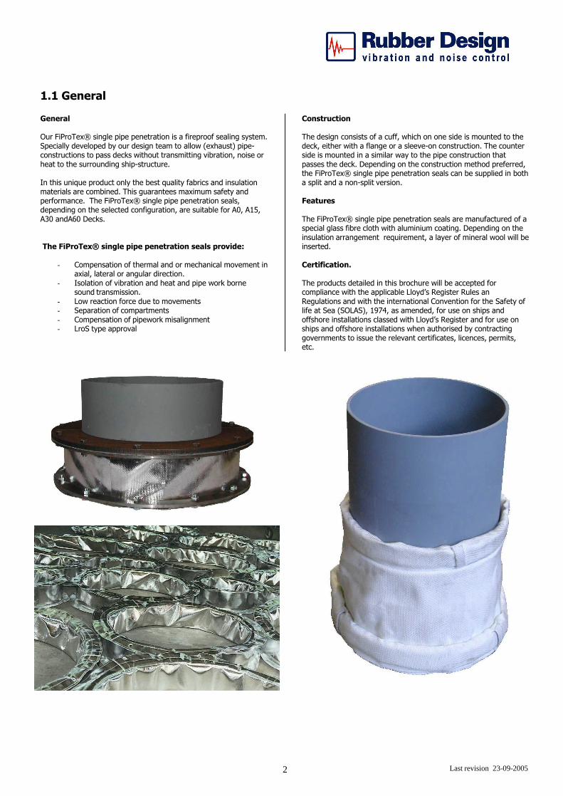
General Our FiProTex® single pipe penetration is a fireproof sealing system. Specially developed by our design team to allow (exhaust) pipe-constructions to pass decks without transmitting vibration, noise or heat to the surrounding ship-structure. In this unique product only the best quality fabrics and insulation materials are combined. This guarantees maximum safety and performance. The FiProTex® single pipe penetration seals, depending on the selected configuration, are suitable for A0, A15, A30 andA60 Decks. The FiProTex® single pipe penetration seals provide:
- Compensation of thermal and or mechanical movement in axial, lateral or angular direction.
- Isolation of vibration and heat and pipe work borne sound transmission.
- Low reaction force due to movements - Separation of compartments - Compensation of pipework misalignment - LroS type approval
Construction The design consists of a cuff, which on one side is mounted to the deck, either with a flange or a sleeve-on construction. The counter side is mounted in a similar way to the pipe construction that passes the deck. Depending on the construction method preferred, the FiProTex® single pipe penetration seals can be supplied in both a split and a non-split version. Features The FiProTex® single pipe penetration seals are manufactured of a special glass fibre cloth with aluminium coating. Depending on the insulation arrangement requirement, a layer of mineral wool will be inserted. Certification. The products detailed in this brochure will be accepted for compliance with the applicable Lloyd’s Register Rules an Regulations and with the international Convention for the Safety of life at Sea (SOLAS), 1974, as amended, for use on ships and offshore installations classed with Lloyd’s Register and for use on ships and offshore installations when authorised by contracting governments to issue the relevant certificates, licences, permits, etc.
Last revision 30-09-2005 3
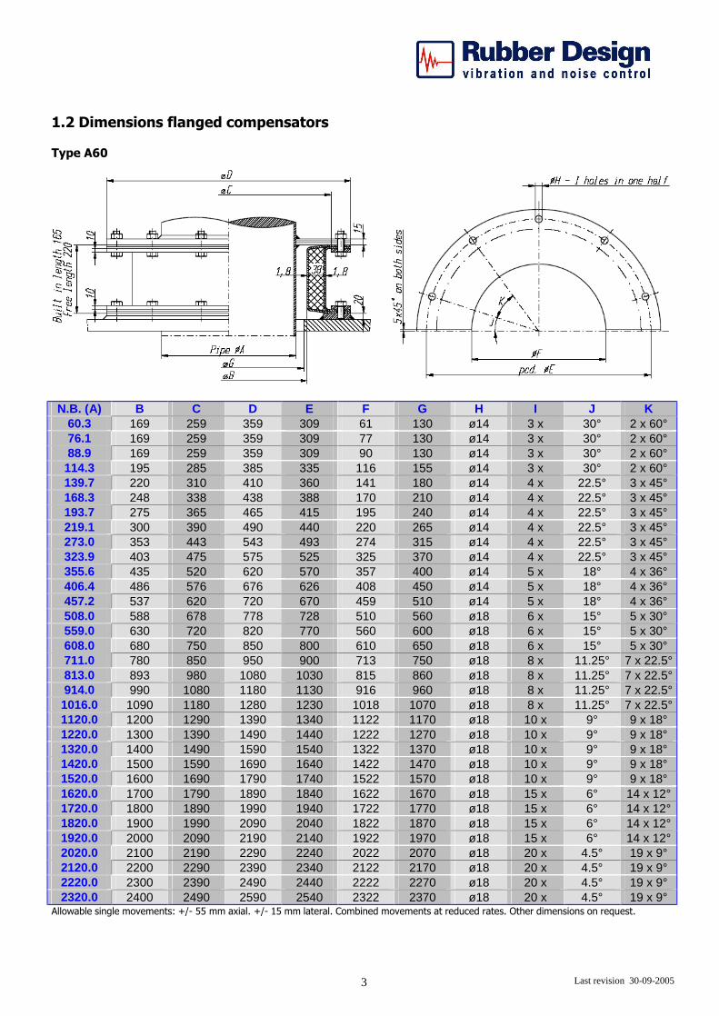
1.2 Dimensions flanged compensators Type A60
N.B. (A) B C D E F G H I J K
60.3 169 259 359 309 61 130 ø14 3 x 30° 2 x 60° 76.1 169 259 359 309 77 130 ø14 3 x 30° 2 x 60° 88.9 169 259 359 309 90 130 ø14 3 x 30° 2 x 60°
114.3 195 285 385 335 116 155 ø14 3 x 30° 2 x 60° 139.7 220 310 410 360 141 180 ø14 4 x 22.5° 3 x 45° 168.3 248 338 438 388 170 210 ø14 4 x 22.5° 3 x 45° 193.7 275 365 465 415 195 240 ø14 4 x 22.5° 3 x 45° 219.1 300 390 490 440 220 265 ø14 4 x 22.5° 3 x 45° 273.0 353 443 543 493 274 315 ø14 4 x 22.5° 3 x 45° 323.9 403 475 575 525 325 370 ø14 4 x 22.5° 3 x 45° 355.6 435 520 620 570 357 400 ø14 5 x 18° 4 x 36° 406.4 486 576 676 626 408 450 ø14 5 x 18° 4 x 36° 457.2 537 620 720 670 459 510 ø14 5 x 18° 4 x 36° 508.0 588 678 778 728 510 560 ø18 6 x 15° 5 x 30° 559.0 630 720 820 770 560 600 ø18 6 x 15° 5 x 30° 608.0 680 750 850 800 610 650 ø18 6 x 15° 5 x 30° 711.0 780 850 950 900 713 750 ø18 8 x 11.25° 7 x 22.5° 813.0 893 980 1080 1030 815 860 ø18 8 x 11.25° 7 x 22.5° 914.0 990 1080 1180 1130 916 960 ø18 8 x 11.25° 7 x 22.5° 1016.0 1090 1180 1280 1230 1018 1070 ø18 8 x 11.25° 7 x 22.5° 1120.0 1200 1290 1390 1340 1122 1170 ø18 10 x 9° 9 x 18° 1220.0 1300 1390 1490 1440 1222 1270 ø18 10 x 9° 9 x 18° 1320.0 1400 1490 1590 1540 1322 1370 ø18 10 x 9° 9 x 18° 1420.0 1500 1590 1690 1640 1422 1470 ø18 10 x 9° 9 x 18° 1520.0 1600 1690 1790 1740 1522 1570 ø18 10 x 9° 9 x 18° 1620.0 1700 1790 1890 1840 1622 1670 ø18 15 x 6° 14 x 12° 1720.0 1800 1890 1990 1940 1722 1770 ø18 15 x 6° 14 x 12° 1820.0 1900 1990 2090 2040 1822 1870 ø18 15 x 6° 14 x 12° 1920.0 2000 2090 2190 2140 1922 1970 ø18 15 x 6° 14 x 12° 2020.0 2100 2190 2290 2240 2022 2070 ø18 20 x 4.5° 19 x 9° 2120.0 2200 2290 2390 2340 2122 2170 ø18 20 x 4.5° 19 x 9° 2220.0 2300 2390 2490 2440 2222 2270 ø18 20 x 4.5° 19 x 9° 2320.0 2400 2490 2590 2540 2322 2370 ø18 20 x 4.5° 19 x 9°
Allowable single movements: +/- 55 mm axial. +/- 15 mm lateral. Combined movements at reduced rates. Other dimensions on request.
Last revision 30-09-2005 4
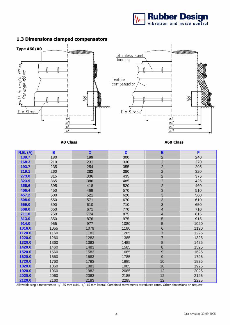
1.3 Dimensions clamped compensators Type A60/A0
A0 Class A60 Class
N.B. (A) B C D E F 139.7 180 199 300 2 240 168.3 210 231 330 2 270 193.7 235 254 355 2 295 219.1 260 282 380 2 320 273.0 315 336 435 2 375 323.9 365 386 485 2 425 355.6 395 418 520 2 460 406.4 450 469 570 3 510 457.2 500 521 620 3 560 508.0 550 571 670 3 610 559.0 590 610 710 3 650 608.0 650 671 770 4 710 711.0 750 774 875 4 815 813.0 850 876 975 5 915 914.0 955 977 1080 5 1020 1016.0 1055 1079 1180 6 1120 1120.0 1160 1183 1285 7 1225 1220.0 1260 1283 1385 7 1325 1320.0 1360 1383 1485 8 1425 1420.0 1460 1483 1585 8 1525 1520.0 1560 1583 1685 9 1625 1620.0 1660 1683 1785 9 1725 1720.0 1760 1783 1885 10 1825 1820.0 1860 1883 1985 10 1925 1920.0 1960 1983 2085 12 2025 2020.0 2060 2083 2185 12 2125 2120.0 2160 2183 2285 12 2225
Allowable single movements: +/- 55 mm axial. +/- 15 mm lateral. Combined movements at reduced rates. Other dimensions on request.
Last revision 30-09-2005 5
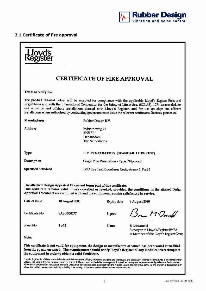
2.1 Certificate of fire approval
Last revision 30-09-2005 6
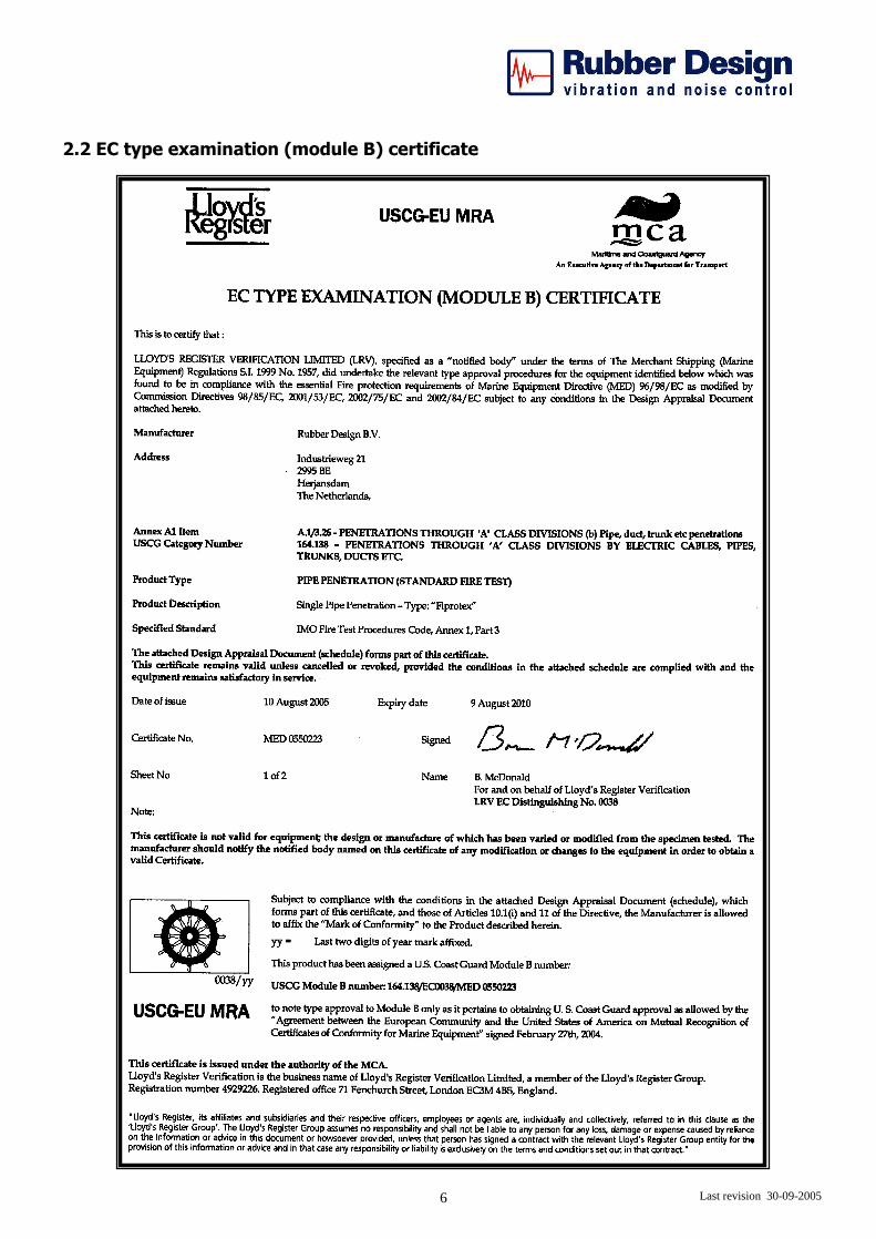
2.2 EC type examination (module B) certificate
Last revision 30-09-2005 7
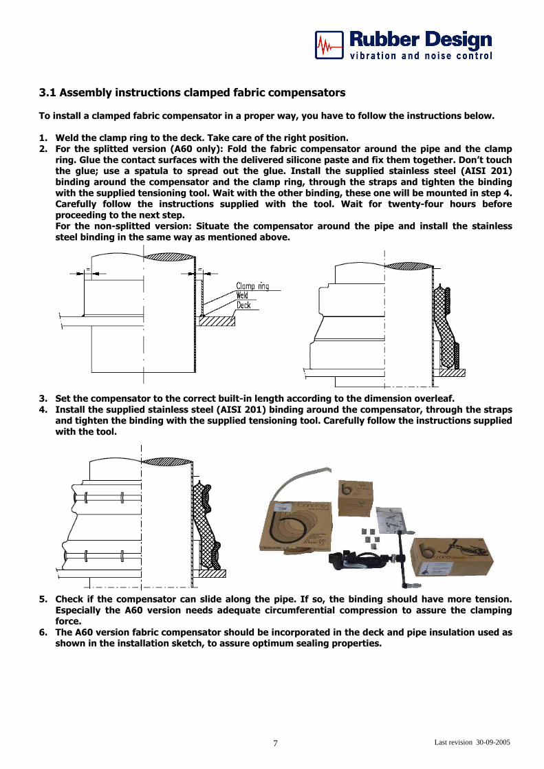
3.1 Assembly instructions clamped fabric compensators To install a clamped fabric compensator in a proper way, you have to follow the instructions below. 1. Weld the clamp ring to the deck. Take care of the right position. 2. For the splitted version (A60 only): Fold the fabric compensator around the pipe and the clamp
ring. Glue the contact surfaces with the delivered silicone paste and fix them together. Don’t touch the glue; use a spatula to spread out the glue. Install the supplied stainless steel (AISI 201) binding around the compensator and the clamp ring, through the straps and tighten the binding with the supplied tensioning tool. Wait with the other binding, these one will be mounted in step 4. Carefully follow the instructions supplied with the tool. Wait for twenty-four hours before proceeding to the next step. For the non-splitted version: Situate the compensator around the pipe and install the stainless steel binding in the same way as mentioned above.
3. Set the compensator to the correct built-in length according to the dimension overleaf. 4. Install the supplied stainless steel (AISI 201) binding around the compensator, through the straps
and tighten the binding with the supplied tensioning tool. Carefully follow the instructions supplied with the tool.
5. Check if the compensator can slide along the pipe. If so, the binding should have more tension. Especially the A60 version needs adequate circumferential compression to assure the clamping force.
6. The A60 version fabric compensator should be incorporated in the deck and pipe insulation used as shown in the installation sketch, to assure optimum sealing properties.
Last revision 30-09-2005 8
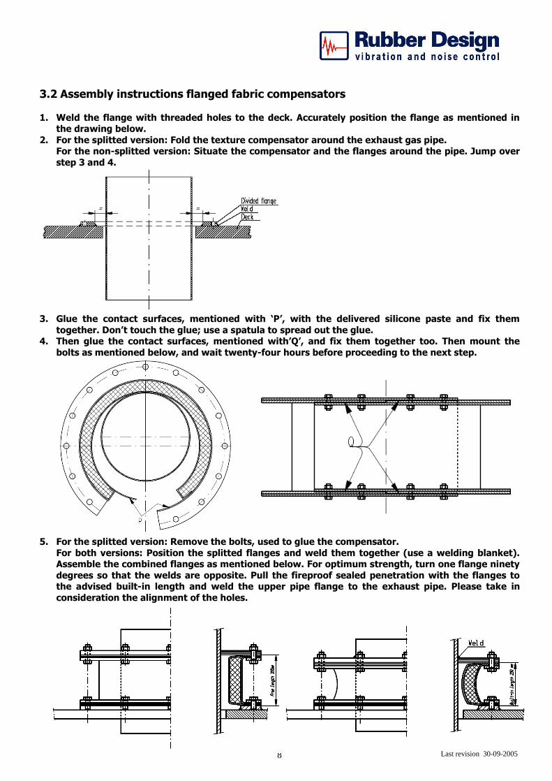
3.2 Assembly instructions flanged fabric compensators
1. Weld the flange with threaded holes to the deck. Accurately position the flange as mentioned in the drawing below.
2. For the splitted version: Fold the texture compensator around the exhaust gas pipe. For the non-splitted version: Situate the compensator and the flanges around the pipe. Jump over step 3 and 4.
3. Glue the contact surfaces, mentioned with ‘P’, with the delivered silicone paste and fix them together. Don’t touch the glue; use a spatula to spread out the glue.
4. Then glue the contact surfaces, mentioned with’Q’, and fix them together too. Then mount the bolts as mentioned below, and wait twenty-four hours before proceeding to the next step.
5. For the splitted version: Remove the bolts, used to glue the compensator. For both versions: Position the splitted flanges and weld them together (use a welding blanket). Assemble the combined flanges as mentioned below. For optimum strength, turn one flange ninety degrees so that the welds are opposite. Pull the fireproof sealed penetration with the flanges to the advised built-in length and weld the upper pipe flange to the exhaust pipe. Please take in consideration the alignment of the holes.