Building Volumetric Appearance Models of Fabric using Micro CT Imaging
Shuang Zhao Wenzel Jakob Steve Marschner Kavita Bala Cornell University
Presenter
Presentation Notes
Hello everyone! Today I will talk about a brand new way of building volumetric models of fabrics.
Fabric Challenging to model and render
Silk satin Gabardine wool Velvet
Presenter
Presentation Notes
Fabrics, being very common in the real world, have long been challenging to model and render due to their complex responses to the light which create a wide range of appearance. Silk satin usually has shiny anisotropic highlights. Gabardine, a wool twill fabric, is less glossy but strongly textured. Velvet produces characteristic grazing-angle highlights. It would be great to have a model that can capture all these effects and reproduce them in the virtual world of computer graphics.
Volumetric
Cloth Appearance Models Surface-based
[Irawan 2008] [Jakob et al. 2010] [Xu et al. 2001] [Ashikhmin et al. 2000]
Presenter
Presentation Notes
Two kinds of models, surface-based and volumetric, have been developed to describe the appearance of fabrics. Surface-based models only consider light-material interactions at one location where the light hits the surface. These models have produced nice results for thin materials, but they lack the power for representing thick ones and the generality for covering fabrics with greatly varying appearance. Volumetric models, on the other hand, explicitly describe light’s scattering within the material. With accurate structural information, very high-quality renderings can be produced using these models. The appearance of fabrics, although varying widely, is mainly determined by their structures. This makes volumetric models particularly suitable for cloth rendering.
Building Volumetric Models A procedural process Requires significant manual effort
[Kaldor et al. 2008]
Presenter
Presentation Notes
Being suitable, however, does not mean easy. The model construction process is normally procedural: a specialized piece of code needs to be written for describing the pattern of yarns for almost every kind of fabric. And writing such programs requires significant manual effort and is tedious, sometimes frustrating. Furthermore, the created models usually lack irregularities, which arises naturally and is one of the key factors for realism.
Our Goal Building high-quality volumetric models automatically
Material sample Volumetric appearance model
Presenter
Presentation Notes
Our goal is to build high-quality volumetric appearance models for fabrics automatically without frustration.
Prior Work Appearance modeling
[Dana et al. 1999], [Wang et al. 2008], … [Kajiya and Kay 1989], [Jakob et al. 2010], …
Cloth reflectance models [Irawan 2008], …
Cloth structure [Shinohara et al. 2010], …
[Shinohara et al. 2010]
[Irawan 2008]
[Jakob et al. 2010] [Wang et al. 2008]
Presenter
Presentation Notes
As prior work, many general appearance modeling techniques have been developed: both surface-based and volumetric. In addition, several reflectance models specific to cloth have been proposed. Since the structure plays an important role in the appearance of fabric, it has been studied by the textile community for decades. Recently, Shinohara et al. introduced a technique that tracks every yarn within a scanned 3D volume of a small piece of fabric.
A new way of building high-quality volumetric appearance models for fabrics
Our Contribution
Silk satin Gabardine Velvet Felt
Model Construction End-to-end pipeline
Rendering New sampling strategy
Presenter
Presentation Notes
Given the significance of fabrics’ structures to their appearance, our contribution is to show how to enhance the structural information for building plausible and consistent optical properties that produce highly realistic renderings. In particular, we developed an end-to-end pipeline consisting of three stages, which we will go into details later, to create volumetric appearance models. Moreover, we derived a new sampling strategy to make Monte Carlo volume path tracing practical.
Desktop micro CT scanner
X-ray Computed Tomography Micro CT scanner in UTCT
CT images Material sample
Silk satin
Velvet
Silk satin
Velvet
Presenter
Presentation Notes
How can we obtain the structural information of a real material sample? Thanks to the modern computed tomography (or CT) technology, now we can get high resolution scans of a piece of fabric in a couple of hours at the cost of several hundred US dollars. This photo shows a micro CT scanner in UT Austin, which has been used to scan all our samples. Next we show CT images, which are scanned slices going from the front to the back of the material. Pixel colors in these images indicate local material densities. In the scan of velvet with a resolution of 5 microns, we first see the tips of the fibers shown as bright dots as they are perpendicular to the screen, followed by the woven backside. In the scan of silk stain with a resolution of 2.5 microns, we first see the parallel yarns on the front surface which create the characteristic highlights, followed by the interlaced remainder. The micro CT technology has been developing rapidly. CT scanners are becoming cheaper, smaller, and easier to use. In the future, it may be possible to obtain high resolution CT scans using a desktop scanner right in your office. We believe it will become a great tool for appearance modeling.
Volumetric Appearance Model
Micro CT image Volumetric appearance model
Extend
Presenter
Presentation Notes
Although the structural information is incredibly important, they cannot be used for physically-based rendering directly. We need an volumetric appearance model that can be built based on the structure and is able to capture characteristic appearance of different kinds of fabrics.
Micro-flake Model
Anisotropic medium Rendered image
[Jakob et al. 2010]
Anisotropic model
Isotropic model
Crucial for cloth rendering
Presenter
Presentation Notes
Fortunately, the micro-flake model introduced by Jakob et al. fits our needs. Unlike traditional models, this model handles volume scattering based on anisotropic media modeled as a collection of small two-sided mirrors, which are called flakes. Intuitively, the micro-flake model is a volumetric version of the micro-facet reflectance model. Images on the right show that the micro-flake model can produce much sharper and more realistic results. Being able to handle anisotropic media is indispensable for capturing any view-dependent behavior such as specular highlights and thus is crucial for modeling the appearance of fabrics.
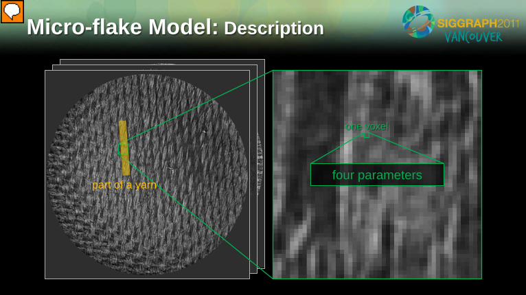
Micro-flake Model: Description
one voxel
four parameters part of a yarn
Presenter
Presentation Notes
In our scanned data, one voxel is normally much smaller than a single yarn, which consists of many fibers. As a volumetric model, the micro-flake model describes every voxel with four parameters. Next, we will go over these parameters in details.
Micro-flake Model: Parameters
Flake density Single-scattering albedo Flake spread Flake orientation
CT image processing Appearance matching
Fiber arrangement Fiber appearance
Presenter
Presentation Notes
For every voxel, flake density, a scalar, tells the number of flakes it contains. Flake orientation, a 3D vector, represents the average normal direction of those flakes. Flake spread, another scalar, describes how well the flakes are aligned along the flake orientation and is similar to surface roughness to surface-based models. Finally, single-scattering albedo, a per-channel scalar, determines the flakes’ reflectivity on that color channel. In the context of cloth rendering, flake density and orientation describe the fiber arrangement, and flake spread and the albedo describe fiber appearance. We assume that the material contains fibers with identical optical property. Then the latter two parameters become global attributes. To build the micro-flake model from a cloth sample automatically, we designed two processes for computing the values of these parameters. CT image processing is performed to obtain flake density and orientation. And appearance matching computes the flake spread and single-scattering albedo.
Our Pipeline
CT image processing Appearance matching Rendering
Micro CT images
Input:
Presenter
Presentation Notes
So our pipeline comes as follows. First, we process the CT images obtained from scanning a small piece of fabric to get density and orientation information for every voxel. Then, we perform appearance matching to compute flake spread and single-scattering albedo. Finally, the volume is tiled across an arbitrary surface and rendered. Next, I will give the details for every stage.
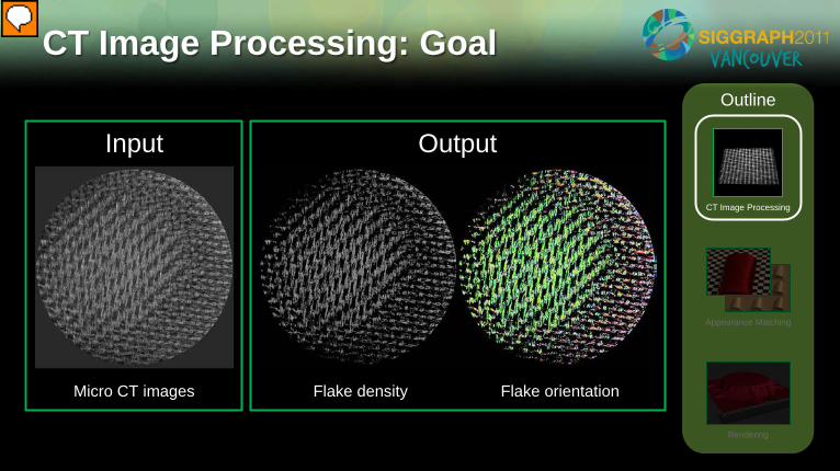
CT Image Processing: Goal
Micro CT images
Appearance Matching
Rendering
CT Image Processing
Outline
Flake density Flake orientation
Input Output
Presenter
Presentation Notes
Let us start with the CT image processing stage. The goal of this stage is to obtain flake density and orientation for every voxel. Note that flake orientation for fabrics is defined to be the direction along which the fibers go locally. CT images, as shown on the left, contain flake density information. Such raw information, however, cannot be used for rendering, since it is often noisy and does not tell the cloth fibers apart from the air. We need to denoise these images to obtain a clean field of flake density, as shown in the middle. The image on the right shows a computed orientation field encoded in false colors.
Fiber orientation detection
Denoising
CT Image Processing
Filter [Shinohara et al. 2010] High Aligned Unaligned Low
Orientation detected Appearance Matching
Rendering
CT Image Processing
Outline
negative positive
Presenter
Presentation Notes
To detect the local fiber orientation at a given point, we applied an approach introduced by Shinohara et al. from the textile community. The basic idea is to use a filter whose shape matches the fibers of the fabric. Here we show a 2D version of this filter, which becomes cylindrical in 3D. The animation shows that the response changes while rotating the filter… and is high when the filter is well aligned with the fiber. The local fiber orientation can therefore be determined by choosing the direction maximizing the response. Finally, a clean density field can be obtained by removing all voxels with maximized response below a pre-picked threshold.
CT Image Processing: Result
Appearance Matching
Rendering
CT Image Processing
Outline
Presenter
Presentation Notes
This is a 3D visualization of the denoised density field. And here is the computed orientation information for silk satin where we first see the green regions indicating vertical fibers and then mixed red & green indicating interlaced horizontal and vertical ones.
CT Image Processing
Flake density Single-scattering albedo Flake spread Flake orientation
Recall that we need to compute flake density and orientation for each voxel as well as flake spread and the albedo for the entire volume. At this point, the former two can be determined as follows. For each voxel, its flake density can be obtained by multiplying the corresponding value in the denoised density field with a pre-determined constant, called density multiplier. We use two main settings of this constant differing by an order of magnitude. And more details are available in the paper. The per-voxel flake orientation is directly given by the computed orientation field. Recall that the remaining parameters, flake spread and single-scattering albedo, are global attributes given the assumption of identical fibers. These parameters will be solved in the appearance matching stage.
Match
Appearance Matching: Goal
Rendering
CT Image Processing
Appearance Matching
Outline
Single-scattering albedo Flake spread
One photo (measured appearance) Rendered image Inverse rendering
problem
Presenter
Presentation Notes
To obtain the values of the remaining parameters, we need something that contains actual appearance of the material. And photographs are a great source of such information. Given a photo of the material sample under known lighting condition, the goal of this stage becomes to compute proper values for flake spread and single-scattering albedo so that the image rendered under the same lighting matches the photo. This is essentially an inverse rendering problem: to solve for optical parameters given the wanted appearance. We use a single photo for appearance matching, and it is possible to use multiple ones with varying lighting and viewing configurations in the future.
Appearance Matching
One photo (measured appearance) Rendered image
Single-scattering albedo Flake spread
Two statistical measures
Mean Standard deviation
What to match?
Rendering
CT Image Processing
Appearance Matching
Outline
Presenter
Presentation Notes
Before trying to solve this inverse rendering problem, we must first define what to match. Again, we assumes that the sample contains only one kind of fiber. Since we do not have pixel-wise registered geometry, we instead match two statistical measures independent of small-scale textures: the mean and the standard deviation of pixel intensities. These measures are computed over manually selected regions indicated with white rectangles to avoid involving background and out-of-focus regions. And the selection can be done easily since the statistical measures are insensitive to small changes of these regions. It turned out that the mean, representing the brightness, is closely related to single-scattering albedo and the standard deviation, representing the contrast, to flake spread.
Appearance Matching
Target
Single-scattering albedo
Flake Spread
Match
How to find the match?
Binary Search Match mean
Match standard deviation
Rendering
CT Image Processing
Appearance Matching
Outline
Presenter
Presentation Notes
Let us look at our search space. We need to find the values of single-scattering albedo and flake spread so that the rendered image matches the photo statistically. But how to find the match? Note that the mean pixel intensity increases monotonically with the albedo and the standard deviation with flake spread. Given this observation, we can solve for the match using binary search. In each iteration, we first fix flake spread and search for the value of the albedo so that the mean pixel intensities match. Then, we fix the albedo and search for the value of flake spread so that the standard deviations match. This method turns out to be quite robust for all our experiments, in which a match can usually be found in 2 or 3 iterations.
Appearance Matching: Result Appearance matching pair
Validation pair (rotated sample, same lighting)
Rendering
CT Image Processing
Appearance Matching
Outline
Presenter
Presentation Notes
Here we show the appearance matching result of silk satin. This photograph is used as the target for appearance matching. And this image is rendered using solved parameters. The second pair is used not for appearance matching but for validation. As shown on the left, when rotating the sample by 90 degrees and draping it to the same curved surface with lighting condition unchanged, the highlights vanish. This is caused by the parallel yarns on silk stain’s front surface which create highly anisotropic reflectance. Our model, which is aware of those structures, successfully predicts the vanishing highlights. This further demonstrates that with the structural information in mind, various virtual effects can be captured using one general and relatively simple appearance model.
Rendering Before rendering… Data Replication
Shellmap [Porumbescu et al. 2005]
Monte Carlo volume path tracing New sampling strategy
CT Image Processing
Appearance Matching
Outline
Rendering
Original data
Tiled data
Presenter
Presentation Notes
Now we have got a complete volumetric appearance model and can start performing physically-based rendering. Due to the limitation of current micro CT scanners, only a small piece of material can be scanned at a time. We performed a randomized tiling technique to extend the data volume for representing larger objects without having visible seams. Finally, we used Shellmap to wrap the tiled volume onto an arbitrary surface. To get best possible quality, we used Monte Carlo volume path tracing implemented by Mitsuba physically-based renderer to synthesize the images. To improve the convergence rate, we developed a new sampling strategy to importance sample the phase function determined by the micro-flake model. For more details, please refer to the paper.
Experimental Results Building Volumetric Appearance Models
of Fabric using Micro CT Imaging
Presenter
Presentation Notes
Next, we show rendering results using volumetric appearance models built with our method.
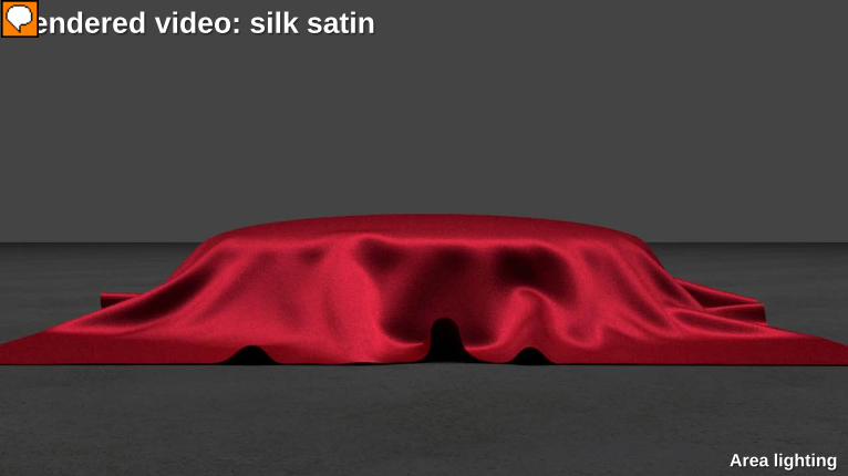
Here is a rendering of silk satin, which has a structure of mainly parallel fibers on the surface, resulting in a strong anisotropic highlight. Our model is able to capture these highlights and convey a convincing impression of silk satin.
Rendered video: silk satin
Area lighting
Presenter
Presentation Notes
Here we show a rendered video of silk satin. Note the smoothly moving highlights on the surface of this material.
For gabardine, the variation in texture with illumination direction is an important appearance characteristic. Our model successfully captures the subtle variations in texture across the surface.
Rendered video: gabardine
Environment lighting
Presenter
Presentation Notes
The appearance model constructed by our method is amazingly detailed: even extreme close-up views remain realistic, revealing the richly detailed fiber structure.
Next we show the results for velvet. Velvet has a visible surface composed of fibers that stick up from the base material, creating a very distinctive appearance with grazing-angle highlight. This effect has been difficult to model. In our system this highlight emerges automatically from the scanned structure.
Felt is a nonwoven textile consisting of a disorganized layer of matted fibers. Our model captures the thickness and fuzziness of this material, which are generally difficult to model and render.
Based on the appearance models created by our technique, various edited results can be obtained. On the left we show a gabardine rendered with blue hue. On the right, we extend the gabardine model with a spatially varying albedo, which is computed as a function of the flake orientation so that fibers in the warp and weft are assigned different colors. And the rendering of this edited model looks like denim. We believe that editing volumetric appearance model of fabric is an interesting research topic and expect to see more work on it in the future.
Conclusions A new way of building volumetric appearance models
The power of structural information Future work
Multicolored fibers, synthesis-based data replication Beyond fabrics and CT
In conclusion, we proposed a new way of building high-quality volumetric appearance models. Our approach uses CT imaging where it is strongest, in measuring 3D structure, and uses photographs where they are strongest, in measuring optical properties. By coupling these inputs using appearance matching, we can create appearance models that are able to capture a large variety of virtual effects: from anisotropic highlights to fuzzy surfaces. In terms of modeling the appearance of fabrics, this level of generality has never been achieved before. We have demonstrated that structural information can be amazingly helpful for appearance modeling. Since CT technology has been developing rapidly and micro CT scanners are becoming increasingly affordable, we expect to see this technique to be used for building appearance models of other structured materials. In the future, we plan to extend this method for handling fabrics with differently colored fibers. We also would like to improve the data replication process using generalized synthesis techniques. Finally, CT imaging is by no means the only modality of acquiring material structure. Alternative technology, such as MRI, may be used to build appearance models of materials whose structures cannot be accurately measured using CT imaging.
Acknowledgements Jessie Maisano Piti Irawan
Funding NSF grants CCF-0644175, CCF-0702490,
CCF-0811680, and IIS-1011919 Intel Autodesk
Presenter
Presentation Notes
We would like to thank Jessie at the UTCT scanning facility, Piti for providing the data and source code for his cloth model, and our funding agencies. And thank you for your attention.


![Building Volumetric Appearance Models of Fabric using ... · Cloth structure: The geometry of cloth structure has been stud-ied for decades [Pierce 1937; Kawabata et al. 1973]. More](https://img.pdfslide.us/doc/110x75/5f647ef22b383d53b859f73d/building-volumetric-appearance-models-of-fabric-using-cloth-structure-the-geometry.jpg)