Embed Size (px)
Citation preview

ARTICLE IN PRESS
Journal ofVisual Languages & ComputingJournal of Visual Languages and Computing
16 (2005) 508–540
1045-926X/$
doi:10.1016/j
�CorrespoE-mail ad
gpolese@uni
www.elsevier.com/locate/jvlc
Building syntax-aware editors forvisual languages
Gennaro Costagliola, Vincenzo Deufemia�,Giuseppe Polese, Michele Risi
Dipartimento di Matematica e Informatica, Universita di Salerno, 84084 Fisciano (SA), Italy
Received 12 December 2004; received in revised form 24 April 2005; accepted 29 June 2005
Abstract
Syntax-aware editors are a class of editors prompting users into writing syntactically correct
programs by exploiting visual language syntax. They are particularly useful in those
application domains where the way a visual symbol spatially relates to others depends from
the context. This does not mean constraining users to enter only correct syntactic states in a
visual sentence, rather it means detecting both syntax and potential semantic errors as early as
possible, and providing error feedbacks in a non-intrusive way during editing. As a
consequence, error handling strategies are an essential part of this editing style.
In this work, we present a strategy for the automatic generation of syntax-aware visual
language editors integrating incremental subsentence parsers into freehand editors. The
proposed parsing strategy has turned out to be useful in many application domains involving
spatial information systems, thanks to the possibility of interactively prompting feasible visual
sentence extensions, and to the presence of a non-correcting error recovery strategy. A first
experimental prototype implementing the whole approach has been embedded into the
VLDesk system, and empirical studies have been performed in order to verify the performance
and the effectiveness of the proposed approach.
r 2005 Elsevier Ltd. All rights reserved.
Keywords: Visual language parsing; Syntax-aware editing; Error-handling
- see front matter r 2005 Elsevier Ltd. All rights reserved.
.jvlc.2005.06.001
nding author. Fax: +39089 963 303.
dresses: [email protected] (G. Costagliola), [email protected] (V. Deufemia),
sa.it (G. Polese), [email protected] (M. Risi).

ARTICLE IN PRESS
G. Costagliola et al. / Journal of Visual Languages and Computing 16 (2005) 508–540 509
1. Introduction
In recent years much effort has been devoted to the development of tools assistingthe designer in the specification and implementation of visual environments [1–5].Visual language development tools raise several interesting issues, including thedefinition of the syntax and semantics of a graphical language, the specification ofcommands for editing, analyzing, and interpreting the rendering of diagrams on thescreen, etc.
Several researchers have exploited visual language grammars to model the syntaxof visual notations, and compiler generators to derive tools capable of processingthem [6]. Some modeling techniques exploit rigorous syntax and semantic modelingto derive freehand editors. These allow users to draw incomplete and incorrectsketches, and to insert visual symbols without any fixed order, postponing the syntaxchecking phase. The latter is invoked at user will. However, there are many methodsimplementing visual notations through dedicated visual editors enforcing a syntax-directed paradigm. Tools based on this approach maintain an internal semanticmodel of the diagram under editing, and check the consistency of the model at everyediting step. Editing actions leading to inconsistent states are rejected. Both freehandand syntax-directed editors have advantages and drawbacks. In general, we can saythat the formers are usually more suitable for experienced users, whereas the latterare more suitable for inexperienced users.
A class of editors combining the positive aspects of both the approaches above isthat of syntax-aware editors. Such editors do not prevent users from enteringincorrect syntactic states in a sentence. However, they inform him/her when objectsare syntactically correct. This means detecting errors as early as possible.
In this paper we propose a parsing technique for the construction of visuallanguage editors supporting the syntax-aware editing style. The generated editorssupport the editing of visual sentences in freehand style. Moreover, the underlyingparsers incrementally analyze the sentences while they are entered, providing animmediate feedback to the user by highlighting correct and incorrect subsentences,and offering additional support for the construction of the sentences. In particular,during the generation of an editor the parsing technique stores information that theeditor exploits to suggest the user how to construct the visual sentence in an easierand more effective way.
The approach is based on eXtended Positional Grammars (XPGs) and on aparsing technique for recognizing visual subsentences. The former is a powerfulgrammar formalism for modeling a broad class of visual languages [3], whereas thenew parsing methodology is based on the incremental and pseudo-parallel version ofTomita’s parsing algorithm developed for string languages [7], and the LR-basedparsing technique introduced in [3]. In particular, we have developed an algorithmfor non-deterministic incremental subsentence parsing, and combined two of themfor the construction of a bidirectional subsentence parser to start the parsing processfrom an arbitrary input symbol. Such parser has been profitably exploited forprompting the continuation of what the user is drawing, and for non-correcting errorrecovery of visual sentences.

ARTICLE IN PRESS
G. Costagliola et al. / Journal of Visual Languages and Computing 16 (2005) 508–540510
The proposed approach has been integrated into a prototype version of theVLDesk system, a powerful visual environment generator based on XPGs [3]. Thegeneration process leads to an integrated environment comprising a graphical editorthat supports the syntax-aware editing style by interacting with a compiler for thedefined visual language. Using the VLDesk system we have performed an empiricalevaluation of parser performance on practical visual languages, and a usability studyto assess the effectiveness of the proposed editing approach.
The paper is organized as follows. In Section 2 we outline the application scenarioof this research. Section 3 describes the main characteristics of the XPG grammarformalism, and shows a technique for parsing visual subsentences of languagesmodeled through XPGs. Section 4 illustrates how the proposed parsing techniquecan be used to prompt the next symbols during the editing process and to implementnon-correcting syntax error recovery. Sections 5 and 6 describe how the approachhas been integrated into the VLDesk system and an empirical evaluation of theproposed editing approach. Section 7 reviews the related approaches. Finally,conclusions and further researches are discussed in Section 8.
2. Motivations
The approach we describe in this article provides a general framework forautomatically generating editors assisting users during the composition of visualsentences.
In this scenario, our approach is mainly targeted to users having a superficialknowledge of the visual language, and particularly useful in presence of visuallanguages having visual symbols whose syntax and semantics highly depend on thecontext surrounding them.
As an example, let us consider the following visual language to be used forstructural design of urban plans. The language provides the possibility to definedifferent geographic areas, such as urban, suburban and industrial areas. Moreover,it is possible to annotate such areas with symbols representing possible buildings,plants, schools, which can in turn be connected to power stations. The buildings inurban areas can be connected to schools, squares, hospital, city hall, and post office.While the buildings in suburban and industrial areas have also to be connected topower stations and hydraulic networks, because these services are not systematicallyexpected in these areas.
Fig. 1 shows a visual sentence of such language. When editing the connectionsfrom a building a user might easily produce incorrect sentences, since the samebuilding icon positioned into different areas needs to be connected in different ways.
Symbol prompting turns out to be particularly useful to support grammardesigners in the testing phase of their grammar specifications. As a matter of fact,thanks to the systems like the VLDesk the user can easily develop a prototype of thevisual environment for the target visual language, and due to the presence of symbolprompting, rapidly verify the visual language. In particular, the presence of symbolprompting limits the number of visual sentences that need be edited in order to test

ARTICLE IN PRESS
Fig. 1. A visual sentence describing a structural urban plan.
G. Costagliola et al. / Journal of Visual Languages and Computing 16 (2005) 508–540 511
the correctness of the grammar specification. In fact, the designer can limit his/herattention to prompted symbols without needing to continuously verify thecorrectness of hypothesized sentences.
3. Recognizing visual subsentence with LR-based parsers
In this section we illustrate the main characteristics of the XPG and theincremental and generalized XpLR technique for parsing visual subsentencesmodeled through XPGs [8].
3.1. Modeling visual languages with XPG
XPGs are a grammar formalism that have been successfully used to model a wideclass of visual languages, including Class diagrams, Petri nets, Statechart diagrams,and Activity diagrams [3]. In the following we introduce the formalism by using theDataflow Diagrams language as running example. Dataflow diagrams are used toshow the functionality of a system: the various processes, and the flows ofinformation which link them to each other, to data stores, and to various entitiesexternal to the system. Thus, a dataflow diagram (DFD) consists of a collection ofprocesses, stores, and entities (visualized by ellipses, parallel lines, and rectangles,resp.) linked by flows. Fig. 2(a) shows a portion of a dataflow diagram, for a businessapplication.

ARTICLE IN PRESS
(a) (b)
Fig. 2. A data flow diagram (a) and its attribute-based representation (b).
G. Costagliola et al. / Journal of Visual Languages and Computing 16 (2005) 508–540512
The formalism conceives a visual sentence as a set of visual symbols withattributes. More formally, a visual symbol (vsymbol, for short) is a graphical objectcharacterized by a physical appearance and a type. The former is described throughthe size, color, shape, etc., whereas the type has associated a set of attributes. Eachattribute can be either syntactic or semantic. Syntactic attributes are used to relate avsymbol to others, and their values depend on the ‘‘position’’ of the vsymbol in thesentence, whereas the semantic attributes describe the semantic interpretation of avsymbol.
In general, the same type may be associated to different graphical objects,similarly to what happens in traditional string languages [9]. The set of graphicalobjects is described by a rule called visual pattern, which is associated with the type.
As an example, let us consider a vsymbol describing the flow of information of aDFD. In this case, a possible graphical object is. It abides by the visual pattern of thetype FLOW describing arrows. The syntactic attributes associated to FLOW are twoattaching points corresponding to the start and end points of the edge, which keeptrack of the links connected to each of them. Whereas the semantic attributes qualifyFLOW as the information flow element in a DFD.
A visual alphabet S is a set of vsymbol types. A visual sentence (vsentence, forshort) on S is a set of vsymbols fx1;x2; . . . ; xng whose types are in S and their(physical and) syntactic attributes are completely instantiated. In this case thevsymbols are named visual tokens or vtokens. In the following we will use the termvsymbol also to refer to the type associated to a vsymbol.
Thus, a visual sentence is specified by combining vsymbols with relations holdingamong their syntactic attributes. As an example, a DFD could be specified byproviding the vsymbols representing nodes (i.e., processes, entities and stores) andedges, and the relations between them. In particular, the syntactic attribute toexpress the attachment relation between the borderline of a node and the end pointof edges can be represented by an ‘‘attaching region’’ on that node. Fig. 2(b) showsthe attribute-based representation of the data flow diagram in Fig. 2(a). Herenode and edge labels have been explicitly represented (the symbols by numbers andthe relations by letters) in light gray only to better describe the corresponding

ARTICLE IN PRESS
G. Costagliola et al. / Journal of Visual Languages and Computing 16 (2005) 508–540 513
attribute-based representation. The node vsymbols have one attaching region as asyntactic attribute while the flow vsymbols have two attaching points as theirsyntactic attributes. The attaching points of a vsymbol are numbered andrepresented by an array aps½1�; . . . ; aps½n�. The value of aps½i� is given by a uniquelabel assigned to the link plugged into attaching point i of v; in the case of attachingregions the value of aps½i� is the set of labels of the links plugged into attaching regioni of v. As an example, the table entry ð4; aps½1�Þ ¼ fb; c; f g means that the vsymbol inrow 4 (whose type is PROCESS) is related through its attaching region 1 to thevsymbols having labels b, c, or f as values of their attaching points or regions (in thisexample the vsymbols of type FLOW in rows 2, 3, and 5, through the attachingpoints 2, 1 and 2, respectively).
An XPG is the pair ðG;PEÞ, where PE is a positional evaluator, and G is aparticular type of context-free string attributed grammar ðN;T [ POS;S;PÞ where:
N is a finite non-empty set of non-terminal vsymbols; T is a finite non-empty set of terminal vsymbols, with N \ T ¼ ;; POS is a finite set of binary relation identifiers, with POS \ N ¼ ; andPOS \ T ¼ ;;
S 2 N denotes the starting vsymbol; P is a finite non-empty set of productions of the following format:A ! x1R1x2R2 . . . xm�1Rm�1xm;D;G
where A is a non-terminal vsymbol, x1R1x2R2 . . . xm�1Rm�1xm is a linearrepresentation with respect to POS where each xi is a vsymbol in N [ T andeach Rj is partitioned in two subsequences
ðhRELh1j1; . . . ;RELhk
jki; hREL
hkþ1
jkþ1; . . . ;RELhn
jniÞ with 1pkpn.
Each RELhi
jirelates syntactic attributes of xjþ1 with syntactic attributes of xj�hi
,with 0phioj. In the rest of the paper, we will denote REL0
1 simply as REL1. Therelation identifiers in the first subsequence of an Rj are called driver relations,whereas the ones in the second subsequence are called tester relations. Driverrelations are used during syntax analysis to determine the next vsymbol to bescanned, whereas tester relations are used to check whether the last scannedvsymbol (terminal or non-terminal) is properly related to previously scannedvsymbols. We refer to the driver (tester, resp.) relations of Rj with driverðRjÞ
(testerðRjÞ, resp.).
D is a set of rules used to synthesize the values of the syntactic attributes of A fromthose of x1;x2; . . . ;xm.
G is a set of triples ðNj ;Condj ;DjÞj ¼ 1; . . . ; t and tX0, used to dynamicallyinsert new vsymbols in the input visual sentence during the parsing process. Inparticular,
Nj is a terminal vsymbol to be inserted in the input visual sentence; Condj is a pre-condition to be verified in order to insert Nj;
ARTICLE IN PRESS
G. Costagliola et al. / Journal of Visual Languages and Computing 16 (2005) 508–540514
Dj is the rule used to compute the values of the syntactic attributes of Nj fromthose of x1; . . . ;xm.Informally, a positional evaluator PE is a materialization function that transformsa linear representation into the corresponding visual sentence in the attribute-basedrepresentation and/or graphical representation. The attribute-based representationof a visual sentence is a list of all the objects forming the sentence together with thevalues of their syntactic attributes.
The language described by an XPG, LðXPGÞ, is the set of the visual sentences fromthe starting vsymbol S of XPG.
In the following we define the notion of reachability between two vsymbols whichwill be used in the description of the parser and in the next section. Given the twopairs ðx; kÞ and ðy; jÞ, where x 2 N [ T , y 2 T , k is a syntactic attribute of x, and j is asyntactic attribute of y, we say that ðy; jÞ is reachable from ðx; kÞ iff one of thefollowing situations occurs:
1.
x ¼ y; 2. there exists a production x ! x1R1x2 . . . xi . . .Rm�1xm, D, G in P such thatattribute k of x is synthesized from attribute h of xi by means of D, and ðy; jÞ isreachable from ðxi; hÞ.
If ðy; jÞ is reachable from ðx; kÞ, we also say that y is reachable from x. As an example,given the productions
A ! Br1Cr2D;D : ðA1 ¼ C2Þ,
C ! c;D : ðC2 ¼ c3Þ,
we have that ðc; 3Þ is reachable from ðA; 1Þ.Thus, the reachability between vsymbols relates the terminal vsymbols to the non-
terminals that synthesize their syntactic attributes, and will be useful during therecognition process to retrieve the next vsymbols to be parsed.
In the following we show an example of XPG grammar modeling the DFDlanguage. Let DFD be the name of the grammar, the set of non-terminals isN ¼ fDataFD;Nodeg, where each vsymbol has one attaching region as syntacticattribute, and DataFD is the starting vsymbol of DFD, i.e., S ¼ DataFD. The set ofterminals is given by T ¼ fPROCESS; STORE;ENTITY;FLOW;PLACEHOLDg.The terminal vsymbols PROCESS, STORE and ENTITY have one attaching regionas syntactic attribute. They represent, the processing step node, the data store (or data
source) node, and the externally entity node, respectively, of a DFD. The terminalvsymbol FLOW has two attaching points as syntactic attributes corresponding tothe start and end points of the edge. Finally, PLACEHOLD is a fictitious terminalvsymbol, i.e., it is not a symbol of the language, to be dynamically inserted in theinput sentence during the parsing process. It has one attaching region as syntacticattribute.

ARTICLE IN PRESS
Fig. 3. The terminals for the grammar DFD.
G. Costagliola et al. / Journal of Visual Languages and Computing 16 (2005) 508–540 515
In Fig. 3, each attaching region is represented by a bold line and is identified by thenumber 1, whereas the two attaching points of FLOW are represented by bullets andare identified each by a number.
The set of relations is given by POS ¼ fLINKh;k; anyg, where the relation identifierany denotes a relation that is always satisfied between any pair of vsymbols, whereasthe relation identifier LINK i;j is defined as: ‘‘a vsymbol x is in relation with avsymbol y iff attaching point i of x is connected to attaching point j of y’’, and will bedenoted as i_j to simplify the notation. Moreover, we use the notation h_k whendescribing the absence of a connection between two attaching areas h and k. The setof productions for DFD follows.
(1)
DataFD ! PROCESS D: DataFD1 ¼ PROCESS1Þ(2)
DataFD ! DataFD0hh1_1i; h1_2ii FLOW 2_1 NodeD: ðDataFD1 ¼ DataFD01 � FLOW1Þ
G: fðPLACEHOLD; true;PLACEHOLD1 ¼ Node1 � FLOW2Þg
(3)
DataFD ! DataFD0hh1_2i; h1_1ii FLOW 1_1NodeD: ðDataFD1 ¼ DataFD01 � FLOW2Þ
G: fðPLACEHOLD; true;PLACEHOLD1 ¼ Node1 � FLOW1Þg
(4)
DataFD ! DataFD0 hanyi PLACEHOLD D: ðDataFD1 ¼ DataFD01 [ PLACEHOLD1Þ
(5)
Node ! Node0hh1_1i; h1_2ii FLOWD: ðNode1 ¼ Node01 � FLOW1Þ
(6)
Node ! Node0hh1_2i; h1_1ii FLOWD: ðNode1 ¼ Node01 � FLOW2Þ
(7)
Node ! STORE D: ðNode1 ¼ STORE1Þ(8)
Node ! PROCESS D:ðNode1 ¼ PROCESS1Þ(9)
Node ! ENTITY D: ðNode1 ¼ ENTITY1Þ(10)
Node ! PLACEHOLD D: ðNode1 ¼ PLACEHOLD1ÞNotice that Node1 ¼ Node01 � FLOW1 indicates set difference and is to be
interpreted as follows: ‘‘the attaching area 1 of Node has to be connected to whateveris attached to the attaching area 1 of Node0 except for the attaching point 1 ofFLOW’’. Notice that the prime marks are used to distinguish different occurrencesof the same vsymbol.
ARTICLE IN PRESS
G. Costagliola et al. / Journal of Visual Languages and Computing 16 (2005) 508–540516
Fig. 4 shows a visual representation of the set of productions for describing DFDs.In particular, the terminal and non-terminal vsymbols are arranged on a two-dimensional space in a way that satisfies the grammar relations. Moreover, icons forvsymbols on the left-hand side are placed in a rectangular box together with theassociated D rules. A similar structure is used for the vsymbols introduced through Grules, with the only difference that the box includes a third area containing theassociated pre-condition.
According to these rules, a DFD is defined as
a processing step node (production 1) or, recursively, as a DFD connected to a node through an outgoing (production 2) or incoming(production 3) edge flow.A node can be either a node connected to an outgoing (production 5) or incoming(production 6) edge flow, or a processing step node (production 7), or a data storenode (production 8), or an entity node (production 9).
During the reduction process, the introduction of the PLACEHOLD terminals(productions 2 and 3) and their successive processing (productions 4 and 10) allow usto keep knowledge of the source and the target node of each reduced edge. The sameresult could be achieved by using the non-terminal Node instead of PLACEHOLD.However, this would let the grammar describe also unconnected graph structures.
Fig. 5(a–k) shows the steps to reduce the data flow diagram in Fig. 2(a) throughthe extended positional grammar DFD shown above. In particular, dashed ovalsindicate the handles to be reduced, and their labels indicate the productions to beused. The reduction process starts by applying production 1 to a processing step
Fig. 4. A visual representation of the productions for DFD grammar.

ARTICLE IN PRESS
(a) (b) (c) (d)
(e) (f) (g) (h) (i) (k)
Production 7
Production 1 Production 3
DataFD
Production 8
Production 9
Production 3
Production 3
Production 4
Production 2 Production 10
Production 4
Production 4
Node
Node Node
DataFD
Node
DataFD
Node
Node Node Node Node
DataFD DataFD
DataFD DataFD
DataFD
DataFD
Fig. 5. The reduction process for a data flow diagram.
G. Costagliola et al. / Journal of Visual Languages and Computing 16 (2005) 508–540 517
node. This causes the terminal PROCESS to be reduced to the non-terminalDataFD. Due to the D rule of production 1, DataFD inherits all the connections ofPROCESS. Similarly, the application of production 7 replaces a STORE vsymbol ofFig. 5(a) with the non-terminal Node. Fig. 5(b) shows the resulting visual sententialform, and highlights the handle for the application of production 3. The vsymbolsDataFD, FLOW, and Node are then reduced to the new non-terminal DataFD. Dueto the D rule of production 3, the new DataFD is connected to all the remainingedges attached to the old DataFD. Moreover, due to the G rule a new nodePLACEHOLD is inserted in the input, and it is connected to all the remaining edgesattached to the old Node as shown in Fig. 5(c).
After the application of productions 8, 9, 2, 10, and 3 the visual sentential formreduces to the one shown in Fig. 5(f). Then, production 4 reduces the non-terminalDataFD and PLACEHOLD to a new non-terminal DataFD. By applying the D ruleof production 4, the new DataFD inherits all the connections of PLACEHOLD (seeFig. 5(g)). The subsequent application of productions 4, 3, and 4 reduces the originalDFD to the starting vsymbol in Fig. 5(k), confirming that the visual sentenceassociated to the initial DFD belongs to the visual language LðDFDÞ.
Let us observe that the text of the labels associated to the flow and node vsymbolscan be the managed by using textual annotations, as done in [3].
3.2. An incremental subsentence parser for visual languages
Parsers based on XPGs are an extension of LR parsing, named XpLR parsing [3].An LR parser takes in input a sequence of tokens and returns a parse tree if thesequence is in the language accepted by the parser [9]. A peculiarity of XpLR parsersis its scanning of the input in a non-sequential way (driven by the relations used inthe grammar). However, this increases the occurrence of parsing conflicts. Indeed, anXpLR parser suffers from the same drawbacks as any other deterministic table-driven parser: the language grammar must be unambiguous and conform to the

ARTICLE IN PRESS
G. Costagliola et al. / Journal of Visual Languages and Computing 16 (2005) 508–540518
limitations of the particular table-generation algorithm, which, in many cases, isquite restrictive and requires significant ‘‘grammar-hacking’’. As an example, statetransition diagrams can be parsed with the XpLR methodology only by using asimple but ad hoc parsing table conflict handling heuristic.
Moreover, an XpLR parser as defined in [3] does not provide any feedback whilethe user composes a sentence. In many cases this is not desirable since a visualenvironment needs to be interactive in order to make the user comfortable with itsuse. In order to give immediate feedback to the user, a visual interactive environmentrequires the use of fast parsing methods. To this aim, in the following we introducean incremental and generalized version of the XpLR parser for recognizing visualsubsentences, namely X-Parser, which is based on the generalized LR parsing (GLR)[7,10].
GLR parsing is a technique for parsing arbitrary context-free grammars thatutilizes conventional LR table construction methods. Unlike deterministic parsers,however, a GLR parser permits these tables to contain conflicts. The conflicts aresuccessfully handled by using a graph-structured stack and by representing thepossible parse tree in a compact way (the packed shared parse forest). Additionally,GLR permits a syntactically ambiguous grammar specification, which is necessarybecause the syntax of many languages, included the visual ones, falls outside theLR(k) class of languages.
The components of an X-parser are shown in Fig. 6 and are detailed in thefollowing.
The input to the incremental parser is a dictionary storing the attribute-basedrepresentation of the modified visual sentence as produced by the visual editor (i.e.,the editor associates each graphical object to a proper type, and instantiates itssyntactic attributes), a parse forest and a graph stack built on the original visualsentence. The parser matches the modified visual sentence with the yield of the parseforest, restructures the parse forest on the base of the modifications, and updates thegraph stack. The match is accomplished by retrieving the objects in the dictionarythrough the Fetch_Vsymbol function according to the driver relations in the
action goto next
XpLR Parsing Table
Incremental X-parsingprogram
(driver program)
ModifiedVisual Sentence
Graph Stack
vsymbol
Next vsymbol request
Output
s0st
sj
sk
si
sv
Parse Forest
S
Fig. 6. The architecture of an X-parser.

ARTICLE IN PRESS
G. Costagliola et al. / Journal of Visual Languages and Computing 16 (2005) 508–540 519
grammar [3]. In other words, starting from a specific vsymbol in the sentence theparser launches the Fetch_Vsymbol function any time it needs to find the nextvsymbol to process.
In case of deletion of a vsymbol in the visual sentence, the parser also receives theidentifier of the deleted vsymbol from the visual editor. This information is used toimprove the parsing performance, since the parsing process can be restarted, byanalyzing the parse forest, from the state in which the parser was before therecognition of the deleted vsymbol.
The graph stack has more than one stack top (usually visualized by circles). Theoperations of Splitting, Combining and Local Ambiguity Packing avoid anexponential growth of the stack during the parsing process [10]. For a highlyambiguous grammar, many parse trees might be generated for the input. The packedshared parse forest allows to share common subtrees, and to pack vertices whoseparse subtrees describe the same portion of input and lead to the same state. Inparticular, when two parsers have the same state on top of their stack, they arejoined in a single parser with a forked stack. A reduce action which goes back over afork in a parse stack, splits the corresponding parser again into two separate parsers.If a parser hits an error entry in the parse table, it is killed by removing it from the setof active parsers.
An XpLR parsing table (see Fig. 7) is composed by a set of rows and is dividedinto three main sections: action, goto, and next. Each row corresponds to a parserstate and is composed of a set of one or more subrows. The action and goto sectionsare similar to the ones used in the LR parsing tables for string languages [9], while
St. Action Goto NEXTPROCESS STORE ENTITY FLOW PLACEHOLD EOI DataFD Node
0 :sh2 :1 (start, DataFD)
1 1 2_ : sh3(1_1, FLOW)
2 1_1: sh4 (1_2, FLOW)3 :sh5 (any, PLACEHOLD)
1
4 acc (end, EOI)2 r1 r1 r1 r1 r1 r1 -3 :sh11 :sh10 :sh12 :sh13 :6 (2_1, Node)4 :sh11 :sh10 :sh12 :sh13 :7 (1_1, Node)5 r4 r4 r4 r4 r4 r4 -
1 1_2: sh8 (1_1, FLOW)
2 1_1: sh9 (1_2, FLOW)6
3 r2 r2 r2 r2 r2 r2 -
1 1_2: sh8 (1_1, FLOW)
2 1_1: sh9 (1_2, FLOW)7
3 r3 r3 r3 r3 r3 r3 -8 r5 r5 r5 r5 r5 r5 -9 r6 r6 r6 r6 r6 r6 -10 r7 r7 r7 r7 r7 r7 -11 r8 r8 r8 r8 r8 r8 -12 r9 r9 r9 r9 r9 r9 -13 r10 r10 r10 r10 r10 r10 -
Fig. 7. The XpLR parsing table for DFD grammar.

ARTICLE IN PRESS
G. Costagliola et al. / Journal of Visual Languages and Computing 16 (2005) 508–540520
the next section is used by the parser to select the next vsymbol to be processed. Anentry next½k� for a state sk contains the pair ðRdriver; xÞ, which drives the parser inselecting the next vsymbol (derivable from x) by using the sequence of driverrelations Rdriver.
The special entry ðstart;SÞ is used to retrieve the first vsymbol to be parsed (whichis a vsymbol reachable from S), for example, a vsymbol of type PROCESS is the firstvsymbol retrieved by the parser constructed from the grammar DFD. Whereas theentry ðend ;EOIÞ is used to check whether the whole input sentence has been parsed.The action and goto entries are named conditioned actions and have the format‘‘Rtester: state’’ and ‘‘Rtester: shift state’’, respectively, where Rtester is a possibly emptysequence of tester relations. A shift or goto action is executed only if all the relationsin Rtester are true, or if Rtester is empty.
The X-parser permits XpLR parsing tables to contain conflicts: when a statetransition is multiply defined, the parser simply forks multiple parsers to follow eachpossibility. The algorithms for the construction of an XpLR parsing table are basedon the notion of item [9].
Fig. 8(a–e) shows the application of the X-parsing algorithm during thecomposition of a DFD. In particular, the top portion of each figure visualizesthe partial sentences created during the editing, while the bottom portions show thecorresponding parse shared forests. The shaded regions highlight the subtreesrecovered from the previous parsing execution.
In our approach the parsing algorithm is invoked by the editor as the visualsentence is modified, and it is immediately possible to tell whether the sentence editedso far is partially or completely accepted, just by looking at the parser state.However, it is worth noting that in the LR parsing of visual languages it is difficult toestablish from which vsymbol of a sentence the parsing process has to start. In fact,the parsing of a DFD with an X-parser starts always looking for a PROCESSvsymbol since, in the grammar, it is the first reachable vsymbol from the startingnon-terminal DataFD. This limitation prevents the parser from the possibility torecognize portions of correct sentences, and consequently prevents the editor toassist the user in the sentence composition. To this aim, the parsing algorithm hasto be modified to overcome the difficulty of starting the parsing process from anyvsymbol of a visual sentence.
(a) (b) (c) (d) (e)
Fig. 8. Incremental parsing of a data flow diagram.

ARTICLE IN PRESS
Fig. 9. The architecture of a bidirectional X-parser.
G. Costagliola et al. / Journal of Visual Languages and Computing 16 (2005) 508–540 521
In [8] an algorithm has been introduced that allows any element of the input to beconsidered as the starting one and, at the same time, assures that the parsing processis not compromised. The algorithm is based on the concepts of substring parsing aspresented in [11]. Since the X-parsing technique linearizes the input at run-time (byscanning the vsymbols in the order specified by the grammar productions), the idea isto use two parsers that proceed in parallel, scanning the input sentence in oppositedirections from an arbitrary starting vsymbol, as shown in Fig. 9. To this aim, thealgorithm creates the XpLR parsing tables for the original XPG grammar G ¼
ððN ;T [ POS;S;PÞ;PEÞ and for its reverse version revðGÞ ¼ ððN;T [ invðPOSÞ;S;P0Þ;PEÞ, where invðRÞ denotes the semantically opposed relation1 of R and P0 isdefined as in [8]. The productions of rev(DFD) follow, whereas Fig. 10 shows thecorresponding parsing table.
1We
same p
vice ve
ð10Þ
DataFD ! PROCESSD: ðDataFD1 ¼ PROCESS1Þ
ð20Þ
DataFD ! Node 1_2 FLOW hh 1_1i; h2_1iiDataFD0D: ðDataFD1 ¼ DataFD01 � FLOW1Þ
G: fðPLACEHOLD; true;PLACEHOLD1 ¼ Node1 � FLOW2Þg
ð30Þ
DataFD ! Node 1_1 FLOW hh2_1i; h1_1iiDataFD0D: ðDataFD1 ¼ DataFD01 � FLOW2Þ
G: fðPLACEHOLD; true;PLACEHOLD1 ¼ Node1 � FLOW1Þg
recall that given two relation identifiers REL1 and REL2, if x REL1 y and y REL2 x hold for the
airs of vsymbols x and y then REL2 is the inverse relation of REL1, i.e., invðREL1Þ ¼ REL2, and
rsa. Notice that inv (h_k) ¼ k_h.

ARTICLE IN PRESS
St. Action Goto NEXTPROCESS STORE ENTITY FLOW PLACEHOLD EOI DataFD Node
0 :sh6 :sh5 :sh7 :sh4 :sh3 :1 :2 (start, DataFD) 1 acc (end, EOI)1 sh12 (1_1, FLOW)
22 sh14 (1_2, FLOW)
1 :11 (any, DataFD) 3
2 r10 r10 r10 r10 r10 r10 -
1 :sh6 :sh5 :sh7 :sh4 :sh8 2_1: 9 (1_1, Node)4
2 :sh6 :sh5 :sh7 :sh4 :sh8 1_1: 10 (2_1, Node)5 r7 r7 r7 r7 r7 r7 -6 r1/r8 r1/r8 r1/r8 r1/r8 r1/r8 r1/r8 -7 r9 r9 r9 r9 r9 r9 -8 r10 r10 r10 r10 r10 r10 :7 - 9 r5 r5 r5 r5 r5 r5 -10 r6 r6 r6 r6 r6 r6 -11 r4 r4 r4 r4 r4 r4 -
12 :sh6 :sh5 :sh7 :sh4 :sh3 2_1: 13 :2 (1_1, DataFD)
13 r2 r2 r2 r2 r2 r2 -
14 :sh6 :sh5 :sh7 :sh4 :sh3 1_1: 15 :2 (2_1, DataFD)
15 r3 r3 r3 r3 r3 r3 -
Fig. 10. The XpLR parsing table for rev(DFD).
G. Costagliola et al. / Journal of Visual Languages and Computing 16 (2005) 508–540522
ð40Þ
DataFD ! PLACEHOLDhanyiDataFD0D: ðDataFD1 ¼ PLACEHOLD1 [ DataFD01Þ
ð50Þ
Node ! FLOWhh1_1i; h2_1iiNode0D: ðNode1 ¼ Node01 � FLOW1Þ
ð60)
Node ! FLOWhh2_1i; h1_1iiNode0D: ðNode1 ¼ Node01 � FLOW2Þ
ð70Þ
Node ! STORED: ðNode1 ¼ STORE1Þ
ð80Þ
Node ! PROCESSD: ðNode1 ¼ PROCESS1Þ
ð90Þ
Node ! ENTITYD: ðNode1 ¼ ENTITY1Þ
ð100Þ
Node ! PLACEHOLDD: ðNode1 ¼ PLACEHOLD1Þ
Note that LðGÞ is equivalent to LðrevðGÞÞ for each XPG grammar G.Once an arbitrary vsymbol x in the input sentence has been chosen, for each state
in G (revðGÞ, resp.) which is possible to reach with x the algorithm starts an X-parser,named forward (backward, resp.) parser. The forward parsers interact with thebackward parsers only when a parser tries to reduce a production requiring the stackto pop its bottom state. In this case, that parser waits for a rendezvous, i.e., anopposite parser attempting to apply the reverse version of the same reduction. Therendezvous produces a new set of forward and backward parsers and the process willcontinue till when either two opposite parsers have a rendezvous on the action

ARTICLE IN PRESS
Fig. 11. Bidirectional parsing of the DFD in Fig. 2(a).
G. Costagliola et al. / Journal of Visual Languages and Computing 16 (2005) 508–540 523
‘‘accept’’ or no rendezvous is possible and the input has all been consumed. Moreformally, a sentence w is recognized by the bidirectional parser if there exist abackward parser B and a forward parser F such that:
(1)
each vsymbol of w is visited by only one of the two parsers, except the startingone that is visited by both, and,(2)
if s1 ¼ xw1 and s2 ¼ xw2 are the subsentences recognized by B and F,respectively, then w ¼ invðw1Þxw2. Notice that x corresponds to the vsymbolfrom which the parsing starts.The forward and backward parser stacks can be considered as only one graph
stack expanding to the right and to the left, and with two types of nodes: simplestack node and joint stack node. The latter encloses a bipartite graph whose elementsare simple stack nodes from forward and backward parsers. Each stack nodeincludes information on the state reached by the parser, the last terminal parsed, anda pointer to a node in the packed shared forest. The incremental parser must controlthat the rendezvous operation can be applied before reusing a subtree. Moreover, thereintroduction of the terminals is local to the couple of forward and backwardparsers that execute the rendezvous.Fig. 11 shows the application of the bidirectional parser to the DFD in Fig. 2(a)where the STORE vsymbol is the starting vsymbol. The first row and the third rowvisualize in black the portions of the sentence recognized by the forward andbackward parsers, respectively. The second row describes the graph stack during therecognition of the sentence. Let us observe that the forward parser immediatelyenters into a wait state, trying to reduce with production (2). When the backwardparser finds a PROCESS vsymbol the forward one wakes up, and the backward oneenters in a wait state, trying to reduce with production ð10Þ, until the forward parsercompletes the recognition of the sentence and tries to reduce with production (1).
4. Symbol prompting and error recovery by using bidirectional X-parsers
In this section we show how to use the bidirectional parser for prompting thecontinuation of what the user is drawing and for implementing non-correctingsyntax error recovery.

ARTICLE IN PRESS
G. Costagliola et al. / Journal of Visual Languages and Computing 16 (2005) 508–540524
4.1. Exploiting parsing information for symbol prompting
In the following we describe how to prompt users to insert vsymbols during thecomposition of a visual sentence. The approach requires the modification of theparsing table construction algorithms in order to extract from the XPG grammarfurther static information about the relations among the grammar vsymbols, and themodification of the parsing algorithm in order to associate dynamic parsing contextinformation to each analyzed vsymbol. By joining the dynamic and staticinformation related to an edited vsymbol the parser is able to determine all thepossible related vsymbols. We also present a simpler symbol prompting strategy thatexploits the information in the next column of the parsing table only.
In the next subsection we introduce some preliminary definitions that will beuseful for showing the proposed method. Section 4.1.2 describes the proposedapproaches to suggest the continuation in the editing of visual sentences.
4.1.1. Preliminary definitions
The following definition introduces the possible relations instantiated by an XPGproduction, that is, the links defined by using explicit relations on the right-hand sideof the productions, and the tie-points defined implicitly in the D rules.
Definition 4.1. Let us consider a production p of the form:
A ! x1R1x2R2 . . . xm�1Rm�1xm;D;G for mX1.
1.
a couple ðM:h;N:kÞ is a link of p if there exists a relation in p that relates thegrammar vsymbols M and N in p through the syntactic attributes h and k,respectively.2.
a couple ðA:h;N:kÞ is a tie-point of p, denoted by ðA:h ¼ N:kÞ, if the syntacticattribute h of A is synthesized from the syntactic attribute k of N, i.e., the value ofA:h depends on N :k.3.
JSETðpÞ denotes the set of links and tie-points associated to a production p.Thus, JSETs contain the relations between vsymbols specified in an XPGproduction, i.e., both the relations defined in the productions explicitly and therelations obtained by applying the synthesis rules D. As an example, let us considerthe XPG DFD presented in Section 3.1. The link in production 5 isðNode:1;FLOW:1Þ; the links in production 2 are ðDataFD0:1;FLOW:1Þ andðFLOW:2;Node:1Þ. The tie-points in production 2 are ðDataFD:1 ¼ DataFD0:1Þand ðPLACEHOLD:1 ¼ Node:1Þ.
The notion of JSET for a production can be extended to the collection of XpLRitem sets used for constructing XpLR-parsing tables [3]. An XpLR item of anextended positional grammar is a production without the D and G rules, and with adot at some position of the right-hand side. However, a dot can never be placedbetween a relation identifier and the terminal or non-terminal vsymbol to its right [3].

ARTICLE IN PRESS
G. Costagliola et al. / Journal of Visual Languages and Computing 16 (2005) 508–540 525
As an example, the production A ! XR1YR2Z, D, G leads to the following fourtypes of XpLR(0) items:
½A ! �XR1YR2Z�, ½A ! X � R1YR2Z�, ½A ! XR1Y � R2Z�, ½A ! XR1YR2Z��
Intuitively, an item indicates how much of a production has already beenexamined during the parsing process and what is yet to come. For instance, the item½DataFD ! DataFD0 � hh1_1i; h2_1iiFLOW� means that the non-terminal DataFD0
has already been seen and a FLOW in relationhh1_1i; h2_1ii with DataFD0 isexpected next. A collection of sets of XpLR items provides the basis for constructingXpLR parsers. To construct such collection for a grammar G, we define anaugmented grammar, obtained by adding the new start vsymbol S0 and theproduction S0 ! S to G, and three functions: Closure, Partition and Goto [3].
By keeping track of the relations among the grammar vsymbols during theconstruction of the XpLR item set collection we are able to prompt the insertion ofcorrect vsymbols during the editing of a visual sentence. Indeed, at each step of theediting process we combine information about the current states of the parsers, eachof which correspond to a set of items, with the relations of the JSETs associated tosuch set of items, which yield the symbols that have been recognized to that pointand those that can be related to them. Such JSETs are named RelationSets and aredefined in the following.
Definition 4.2. Given an item I in an item set K, the set RelationSet of I, denoted byRelationSet(I), is defined as follows:
if I is the item S0 ! �S then RelationSetðIÞ ¼ ;; if I: A ! �a then RelationSetðIÞ ¼ JSETðA ! aÞ [ RelationSetðJÞ where J is theitem in K such that I 2 ClosureðJÞ [3]; if I: A ! aR1x � R2b then RelationSet(I) is the RelationSet associated to the itemJ: A ! a � R1xR2b where the syntactic attributes of the grammar vsymbol x aremarked. A marked syntactic attribute k of a grammar vsymbol x is denotedby x:k.The first rule initializes to empty the RelationSet of the item from which thecollection of XpLR item sets is constructed. The second rule establishes that theRelationSet of an XpLR item I whose dot is at the left end (i.e., the vsymbols of theproduction have not yet examined by the parser) is the union of the JSET associatedto corresponding production and the RelationSet of the item J such that I 2
ClosureðJÞ [3]. This means that RelationSetðIÞ contains the relations between thegrammar vsymbol in I and those in J, and recursively those in the items in which hasbeen applied a Closure operation. In the case the XpLR item set I is obtained fromthe Goto operation on a set J and a vsymbol x, then the third rule associates to I theRelationSet of J with the attributes of x marked as examined.
As an example, let us consider the XPG DFD. A subset of the sets of XpLR itemcollection with the associated RelationSet is shown in Fig. 12. In such figuresuperscripts are used to distinguish different occurrences of the same vsymbol indifferent items.

ARTICLE IN PRESS
Fig. 12. A subset of the XpLR item collection for the XPG DFD and the associated RelationSets.
G. Costagliola et al. / Journal of Visual Languages and Computing 16 (2005) 508–540526
Adding to each item the corresponding RelationSet, we have the notion ofextended item. In particular, an extended item I is a pair ½J; JS� where J is an XpLRitem and JS ¼ RelationSetðJÞ.
The algorithms for the construction of XpLR parsing tables presented in [3] can beeasily modified in order to construct such sets. However, suitable care must be takento ensure the termination of the procedures. As a matter of fact, if the grammar isrecursive, a loop may occur when generating the collections of XpLR extendeditems. As an example, let us consider the production DataFD ! DataFDhanyiPLACEHOLD. During the construction of the item set containing the itemDataFD ! �DataFDhanyi PLACEHOLD the closure operation goes into a loop.Indeed, we have the following infinite sequence of items:
DataFD0 ! �DataFD1hanyiPLACEHOLD1
DataFD1 ! �DataFD2hanyiPLACEHOLD1
DataFD2 ! �DataFD3hanyiPLACEHOLD1
..
.
In order to stop the generation of infinite extended items we do not consider thesuperscripts associated to the symbols, since a cycle in the construction of item setsdoes not produce any new information for the RelationSets.
4.1.2. Symbol prompting
RelationSets can be exploited for prompting the possible vsymbols that can berelated to a particular vsymbol of a visual sentence, since they include information ofboth driver and tester relations occurring in the grammar productions, differentlyfrom the next column entries in the parsing table where only driver relations arestored. As a consequence, two strategies of symbol prompting can be supported. Thefirst one, targeted to unexperienced users of the visual language being considered,exploits the entries in the next column to suggest the possible vsymbols that can beinserted into the vsentence together with their relations. In this case, the vsymbols to

ARTICLE IN PRESS
G. Costagliola et al. / Journal of Visual Languages and Computing 16 (2005) 508–540 527
be prompted depend on the form of the grammar productions. The second strategy,targeted to grammar designers and to users with deeper knowledge of the visuallanguage, exploits the information in the RelationSets to suggest the vsymbols thatcan be related to a particular vsymbol in the edited vsentence. As an example, Fig. 13shows a DFD where the STORE vsymbol is the starting vsymbol in the parsingprocess, the dashed vsymbols are those prompted by the first prompting technique,whereas the vsymbols in gray are those prompted by the second technique whenapplied to the vsymbol STORE of the diagram.
The following algorithm implements the first strategy, that is, it determines thenext vsymbols in a vsentence considering the parser state only.
Function Simple_Prompt_Symbol(int j)begin
let s ¼ p½j�;let next_set ¼ ;;
for each couple ðRdriver;xÞ in next½s� where Rdriver ¼ hRELh11 ; . . . ;RELhn
n i do
for each RELhi
i acting on a syntactic attribute ki of x do
let zi be the hi-th vtoken below the stack top;let next_seti ¼ fb 2 T jb has an attribute h such that (b, h) is reachable from
ðx; kiÞ,the relation RELi acts on a syntactic attribute of zi
and the syntactic attribute h of b, respectively g;let next_set ¼ next_set [ ð\i¼1...nnext_setiÞ;
return next_set;
Since the parsing algorithm is non-deterministic, we use an array p storing thestate of each parser. Thus, given the index of a parser, the algorithm stores in s thestate of parser j. Successively, it accesses to the next column and analyzes its entriesðRdriver;xÞ determining all the vsymbols reachable from such couples. In particular,
Fig. 13. A DFD with the symbols prompted by the two proposed strategies.

ARTICLE IN PRESS
G. Costagliola et al. / Journal of Visual Languages and Computing 16 (2005) 508–540528
the set next_set stores all the vsymbols able to satisfy all the relations in Rdriver.Notice that this algorithm has to be executed for both the forward and backwardparsers, and the set of vsymbols to be prompted is given by the union of the returnedsets. Moreover, the algorithm is applied to the parser that has recognized morevsymbols in the vsentence.
Fig. 14 shows the vsymbols returned by the previous algorithm during thecomposition of a DFD diagram. Such vsymbols are drawn as dashed or withinshaded areas. The first edited vsymbol, that is an ENTITY vsymbol, is the startingsymbol of the forward and backward parsers, and can be related to incoming oroutcoming edges as shown in Fig. 14(a). After the editing of an outcoming flow edge(see Fig. 14(b)), we have that the entity can always be related to incoming oroutcoming edges, whereas the edge can be related to a process, or an entity, or a datastore. By selecting the process symbol we have that the algorithm returns the flowedges that can be connected to the process and entity symbols as shown in Fig. 14(c).Finally, Fig. 14(d) shows the prompted symbols obtained by connecting anoutcoming edge to the process symbol.
The idea of the previous prompting approach is to guide the user into a sort ofsequence in the construction of a visual sentence, since the prompted symbols aredetermined considering only the current states of the parsers. Further informationare required to prompt the possible vsymbols that can be related to a particularvsymbol in a vsentence. In this case, we need to associate to each edited vsymbol theparsing information specifying the context in which it has been recognized. Inparticular, during the parsing process for each edited vsymbol we need to keep trackof the grammar vsymbols that synthesize its syntactic attributes. Thus, we associateto each vsymbol T a set of couples (GS:x, s) where GS is the grammar vsymbol thathas associated the syntactic attribute x of T due to the application of subsequentsynthesis rules, and s is the state of the forward or backward parser when thevsymbol GS has been processed. By analyzing the RelationSets of the extended itemsset Is of the forward or backward parser we extract the couples ðGS:x;NS:yÞwith NS:y unmarked attribute, and consider as vsymbols to be prompted all thevsymbols NS.
As an example, Fig. 15(a) shows a DFD where each symbol has associated the setof couples computed during the parsing, while Fig. 15(b) shows the parse treeproduced by the forward parser. The dashed lines in the tree represents the synthesisof the attributes, in particular, the syntactic attribute 1 of PROCESS is synthesizedfirst by DataFD through production 1, then by DataFD0 through production 2;
(a) (b) (c) (d)
Fig. 14. An example of symbol prompting based only on next column information.

ARTICLE IN PRESS
(a) (b) (c)
Fig. 15. A simple DFD (a) and the parse trees annotated with synthesis information produced by the
forward parser (b) and the backward parser (c).
G. Costagliola et al. / Journal of Visual Languages and Computing 16 (2005) 508–540 529
whereas the syntactic attribute 1 of ENTITY is synthesized first by the introducedPLACEHOLD vsymbol through production 2, then by DataFD0 through produc-tion 4. The corresponding backward parser simply reduces the PROCESS vsymbolto another DataFD vsymbol object through production 10 as shown by the parse treein Fig. 15(c).
For such couple of forward and backward parsers the PROCESS vsymbol hasassociated the two couples ðDataFD:1; 4Þ and ðDataFD:1; 10Þ, whereas the coupleðDataFD:1; 4Þ is associated to the ENTITY vsymbol. The FLOW vsymbol has nocouple associated since its attributes are not synthesized during the parsing. Thus,the vsymbols prompted by the forward and backward parsers on the PROCESSvsymbol are determined by analyzing the set of extended items I4 of the forwardparser and the set I 01 of the backward parser. In particular, by searching inRelationSetðI4Þ and RelationSetðI 01Þ the unmarked vsymbol attributes related toDataFD:1, since DataFD is the root of both the parse trees. As shown by the portionof extended item sets I4 and I 01 in Fig. 16 these vsymbol attributes are FLOW.1 andFLOW.2. This means that the start point or the end point of a FLOW vsymbol canbe connected to the borderline of the PROCESS vsymbol.
Given a vsymbol V in the vsentence and its syntactic attribute j, the followingalgorithm determines the vsymbols that can be related to it.
Function Prompt_Symbol (int k, vtoken V , attr j)begin
let s ¼ p½k�;let y be the syntactic attribute of non-terminal or terminal X that has inherited
the syntactic attribute j of V in the parser k;extract from RelationSetðsÞ the couples ðX :y;Z:tÞ with Z:t unmarked;return the sequence of unmarked Z:t;
4.2. Non-correcting syntax error recovery
In a syntax-aware editor if a visual sentence fails to satisfy the rules of thelanguage the parser must be able to indicate the piece of input that caused the failure.

ARTICLE IN PRESS
1_2
1_2 2_11_1
1_11_1
Fig. 16. A portion of extended item sets I4 and I 01.
G. Costagliola et al. / Journal of Visual Languages and Computing 16 (2005) 508–540530
Further, the parser must be able to recover from syntactic parse errors in order toallow the parsing of the remaining part of a sentence.
Notice that the parsing process of a visual sentence may fail
(i)
when the Fetch_Vsymbol function does not find the requested vsymbol, or (ii) when the last analyzed vsymbol is not properly related through the testerrelations to the previously analyzed vsymbols.
Moreover, as defined in [12] a global parsing failure means that (1) all the parallelparsers initiated by the arbitrary starting vsymbol failed, or that (2) at least one ofthe parsers succeeded, but there is unprocessed input left by each successful parser.In the first case, the parser-defined error is the set of input vsymbols causing theparse action failures at the end of the longest parse paths starting from the arbitrarypoint. Fig. 8(b) shows an example of this type of failure caused by the FLOWvsymbol. Note that there can be several equally long parse paths. In the second caseof failure, the parser-defined error is the set of extra input objects. Fig. 8(d) shows acorrect sentence with an extra vsymbol STORE causing this type of failure.
If the parser finds an error, it could try to correct it in order to continue parsing.However, if the parser makes false assumptions about the kind of error encounteredthen spurious errors are easily introduced.
In our approach, the parser does not make any assumption about how to correctthe error, nor skip input until a trusted vsymbol is found. In particular, if a parserdetects a parsing failure on some vsymbol, the subsentence parser is started on anunparsed vsymbol to discover additional parsing failures.
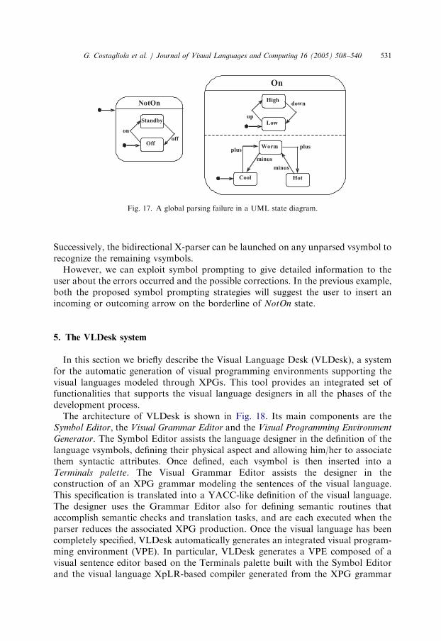
As an example, the UML state diagram in Fig. 17 contains a syntax error: the twoAND-states NotOn and On are not connected. Thus, if the parsing process startsfrom the state High then only the state On and its substates will be parsed.
ARTICLE IN PRESS
Fig. 17. A global parsing failure in a UML state diagram.
G. Costagliola et al. / Journal of Visual Languages and Computing 16 (2005) 508–540 531
Successively, the bidirectional X-parser can be launched on any unparsed vsymbol torecognize the remaining vsymbols.
However, we can exploit symbol prompting to give detailed information to theuser about the errors occurred and the possible corrections. In the previous example,both the proposed symbol prompting strategies will suggest the user to insert anincoming or outcoming arrow on the borderline of NotOn state.
5. The VLDesk system
In this section we briefly describe the Visual Language Desk (VLDesk), a systemfor the automatic generation of visual programming environments supporting thevisual languages modeled through XPGs. This tool provides an integrated set offunctionalities that supports the visual language designers in all the phases of thedevelopment process.
The architecture of VLDesk is shown in Fig. 18. Its main components are theSymbol Editor, the Visual Grammar Editor and the Visual Programming Environment
Generator. The Symbol Editor assists the language designer in the definition of thelanguage vsymbols, defining their physical aspect and allowing him/her to associatethem syntactic attributes. Once defined, each vsymbol is then inserted into aTerminals palette. The Visual Grammar Editor assists the designer in theconstruction of an XPG grammar modeling the sentences of the visual language.This specification is translated into a YACC-like definition of the visual language.The designer uses the Grammar Editor also for defining semantic routines thataccomplish semantic checks and translation tasks, and are each executed when theparser reduces the associated XPG production. Once the visual language has beencompletely specified, VLDesk automatically generates an integrated visual program-ming environment (VPE). In particular, VLDesk generates a VPE composed of avisual sentence editor based on the Terminals palette built with the Symbol Editorand the visual language XpLR-based compiler generated from the XPG grammar

ARTICLE IN PRESS
Fig. 18. The VLDesk architecture.
G. Costagliola et al. / Journal of Visual Languages and Computing 16 (2005) 508–540532
and semantic routines. A final user can then use the VPE to compose and processvisual sentences from the implemented language.
In the new prototype version, the VLDesk is based on the bidirectional X-parserpresented in the previous section. As a consequence the generated VPE supports theproposed syntax-aware editing style of visual sentences. In fact, during theconstruction of the visual sentence, the generated editors are able to suggest a setof possible symbols, based on the two strategies proposed in the previous section,that the user can add to the phrase being constructed.
As an example in Fig. 19 the symbol Processing is selected by the user and thepossible symbols that can be related to its syntactic attributes are shown at thebottom. In the case of state vsymbols of statecharts, they have an attaching regioncorresponding to the borderline of the state, and one containment area correspond-ing to the rectangle area representing the state. On the attaching region the user canconnect an incoming or outcoming arrow, whereas in the containment area the usercan draw only the symbol indicating an initial state. As shown in the figure, when theprompted symbol is selected a preview of the resulting visual sentence is shown in themain window with the prompted symbol highlighted.
Fig. 20 shows the statechart editor generated with VLDesk. The edited statechartis syntactically incorrect since the containment area of the OR-state Processing doesnot contain an initial state. The shaded area shows the containment area involved inthe error. Moreover, the missing initial state is also reported when the parserprocesses the internal states of Processing. In this case, the editor highlights theborderline of one of the states. A user can visualize an error message window wherethe description of the problem is detailed. The two subsentences recognized by theparser are colored with two different colors.

ARTICLE IN PRESS
Fig. 19. Symbol prompting within a visual editor generated with VLDesk.
G. Costagliola et al. / Journal of Visual Languages and Computing 16 (2005) 508–540 533
6. Empirical evaluation
We have performed an empirical evaluation of parser performance and a usabilitystudy to assess the effectiveness of the proposed editing approach. The tests werecarried out on a Pentium Centrino 1.5GHz machine running MS Windows XPoperating system. The performances of the parsing technique have been analyzed onsix different visual languages developed with the VLDesk system. The visuallanguages are DFDs, state transition diagrams, UML class diagrams, UML statediagrams, flowcharts, and the GIS language for urban planning introduced inSection 2. For each of such languages the performance tests have been carried out ontwo different parsers, both integrated into the visual environment generated withVLDesk. The first is the XpLR parser introduced in [3], which is deterministic, notincremental and not bidirectional, whereas the second is the bidirectional X-parser(bi-X) introduced in this paper. Table 1 reports some details about the grammarspecifications used for constructing the parsers and some statistic data obtained byrunning the parsers on sentences with various sizes. Notice that the grammarspecifications for implementing the XpLR parsers require a greater number ofproductions with respect to the corresponding bi-X parsers, since the designer needto solve more ambiguities in the grammar. For each visual language we haveconsidered three correct sentences having 20, 50 and 100 symbols, respectively. In

ARTICLE IN PRESS
Table 1
Performances of XpLR parsers and bidirectional X-parsers on practical visual languages
Fig. 20. Error reporting and symbol prompting to support error correction.
G. Costagliola et al. / Journal of Visual Languages and Computing 16 (2005) 508–540534
order to evaluate the performances of the XpLR parsers we have simply edited thediagrams within the VLDesk generated environment and have invoked the parser.To evaluate the bi-directional X-parsers we have calculated the time to parse the

ARTICLE IN PRESS
G. Costagliola et al. / Journal of Visual Languages and Computing 16 (2005) 508–540 535
intermediate sentences created during the editing process. In Table 1 we report theaverage and maximum of such times. As an example, for a DFD of 50 symbols wehave that the XpLR parser has a time of 0.030 s, whereas the average time of thebidirectional X-parser to recognize the intermediate subsentences is 0.032. Althoughthe bidirectional X-parser underperforms the XpLR parser, the experimental resultshave shown that on real-size visual sentences there is a reduced performance gap,which is largely recovered in terms of system usability, as shown below. In fact, withXpLR we cannot have highly interactive environments. Moreover, another strengthpoint of the proposed approach is the simplification of the grammar specificationprocess achieved through the use of a non-deterministic algorithm.
Table 2 shows the performance of the bi-X parsers with respect to the operationsof insertion, modification and deletion of symbols on sentences of differentlanguages and with various sizes. The values are calculated as the average of thetimes obtained by performing 10 different insertion, modification and deletionoperations on sentences having 20, 50 and 100 symbols, respectively. It can be notedthat the times for the modification of symbols are slightly greater of the times for theinsertion of a new symbol. This is due to the fact that most of the modificationschanged the syntax of the sentences, thus requiring a wide reconstruction of theparse forest by the parsers. Moreover, in several cases the time to parse a newsentence obtained by deleting a symbol is almost half the time for parsing a sentencewith a new or modified symbol.
We have conducted a usability study to assess the effectiveness of the proposedapproach. The diagrammatic language used in the experiment was UML classdiagrams annotated with UML state diagrams. In particular, we have asked 30students of a Software Engineering course to solve an UML exercise involving alarge number of symbols. Before this, we asked them to undergo a pre-test on theUML language. Therefore, based upon the pre-test scores, we separated studentsinto two groups A and B in such a way to have the same score distribution in bothgroups. Students of group A received a 30min tutorial about the features of symbolprompting and error correction provided by the syntax-aware editors. Students of
Table 2
Average times of bi-X parsers for processing 10 insertions, modifications and deletions of symbols on
sentences with various sizes

ARTICLE IN PRESS
Fig. 21. Statistical results from the usability study (a) and the users’ task completion times histogram (b).
G. Costagliola et al. / Journal of Visual Languages and Computing 16 (2005) 508–540536
group A have used the syntax-aware editor generated with VLDesk to complete theexercise, whereas those of group B have used a freehand editor generated with aprevious version of VLDesk that included an XpLR parser.
Results about the experiment are summarized in Fig. 21(a). We can notice that thesyntax-aware editor has considerably reduced (about 12%) the average taskcompletion time thanks to a reduced average number of editing operations requiredto solve the same exercise. The level of dispersions of average task completion timesrepresented by the standard deviation for syntax-aware editors is smaller than thatfor freehand editors. This is mainly due to the fact that syntax-aware editors reducethe times of users with not so much grasp of the visual language (as highlighted in thehistogram of users’ task completion times shown in Fig. 21(b)). As a consequence,for such users the new features provided by syntax-aware editors require not somuch time to be understood and from that moment on, the time to complete the taskis considerable reduced. Freehand editors, on the other hand, do not offer support toedit the sentences, thus the times to complete the task reflect the capacity of users tosolve the exercise independently from the available tool.
Regarding the editing operations, the greater number resulting for freehandediting is mainly due to a greater number of editing errors. This provides someevidence that prompting helps reducing editing errors. Moreover, in this experimentwe have noticed that users tended to accept prompts, since they accept more thenhalf of them. Finally, we have observed that the reduction of editing operations wasin part due to the fact that users found easier to integrate correct subsentences ratherthan unparsed subsentences, since their correction turned out to be much more acomplex task after integration.
7. Related work
In the literature there are many different grammar-based approaches forspecifying visual languages [4]. Some of the tools based on these grammar

ARTICLE IN PRESS
G. Costagliola et al. / Journal of Visual Languages and Computing 16 (2005) 508–540 537
formalisms support the freehand editing style [13,14] others the syntax-directedediting style [15]. In the last years, to overcome the limitations of these editing styleseveral approaches have been proposed.
The intelligent diagram metaphor is a recent metaphor in which the editor parsesthe diagram as it is being constructed, while performing error correction andcollecting geometric constraints that capture the relationships betweendiagram components. This metaphor is supported by the editors generated withthe visual programming environment generator Penguins [2]. In such editors thediagrams are created in free form and in any order. During diagram manipulationobjects in the diagram can be moved or resized while the constraint solvermaintains the semantics by preserving the geometric constraints between thediagram components. Penguins leverages a constraint solver that is able to maintainarbitrary linear arithmetic constraints necessary for geometric error correction anddiagram manipulation. The error correction mechanism used in Penguins is based onthe concept of the geometric distance between sentences. By computing thegeometrically closest sentence that belongs to the language, an incorrect sentencecan be automatically corrected by changing attribute values of the graphicalsymbols.
The issue of incorporating both editing the freehand and the syntax-directedediting modes into one editor has also been analyzed by Minas in [5]. They proposethe hypergraph grammars for the specification of visual languages, and graphtransformation rules for adding syntax-directed editing to the freehand editingmode. In particular, after each editing operation the corresponding transformationrules modify the internal hypergraph, which is then reparsed to indicate thecorrectness and to create a valid layout. The approach implemented into DiaGenalso contains an error-recovering strategy with immediate feedback to the user [5].
In GenGED the syntax specification of visual models is the basis for theconfiguration of a visual environment for syntax-directed or freehand editing [1]. Inparticular, a syntax grammar is used to specify the editing command (i.e., rules aredefined for modification, deletion, etc. of graphical elements), whereas a parse
grammar is used to define a parser that tries to recognize the edited diagrams. Thesespecifications based on algebraic graph transformation allow comprehensive editingand analysis of visual sentences.
An error handling strategy for the parsing algorithm based on atomic relationalgrammars has been proposed by Tuovinen [12]. The error recovery techniques aim atenabling the parser to continue processing the input in spite of syntactic errors ratherthan correcting the errors. In particular, the two techniques, namely patching anddetouring, ignore some erroneous part of input by creating new parse states from thestates representing the dead-ends on a parse path.
The approach proposed in this paper allows us to include interactivity into afreehand editor similarly to what has been done in [2]. However, it does not take intoaccount the problem of maintaining consistency between the symbols during theirmanipulation. On the other hand, an important aspect of our approach, not treatedby the previous quoted tools, is the assistance provided to the user in thecomposition of the visual sentences. Moreover, our error handling strategy attempts

ARTICLE IN PRESS
G. Costagliola et al. / Journal of Visual Languages and Computing 16 (2005) 508–540538
to find as many errors in the input as possible, similarly to Tuovinen’s andMinas’s approaches, but it does not take into consideration their correction. Asopposed to Tuovinen’s approach we try to group the input sentence symbolsinto correct subsentences, without ignoring portions of them. However, theproposed symbol prompting strategies enhance the capability of the user to detecterrors and their possible correction. Another strength point of our approach is thecapability to provide an efficient parser without limiting the modeling power. Inparticular, we have used a non-deterministic incremental predictive parser where theinput objects are processed according to an ordering criterion specified in thegrammar. The proposed parsing schema is conceptually similar to the incrementalbottom-up parsers for attributed graph grammars [2], even though our parsingprocess starts from a symbol in the sentence instead of ‘‘repeatedly using satisfiableproduction rules in the grammar to combine symbols into larger and larger parsetrees’’ [2].
Recently, several metamodeling approaches have been proposed for thespecification and modeling of visual languages [16–20]. In general, metamodelingapproaches are sufficiently simple to use because meta-languages are similar to thelanguages they model, hence they might be easily understood and deployed.However, their empirical and informal descriptions are not sufficient for verifyingcertain properties of the notations they model. In fact, in order to solve this problemthey have been combined with formal specification languages, such as Z [21] andOCL [22], providing the ability to express constraints in a textual form, in order torestrict the number of meaningful notations. In spite of these extensions, we still needto include additional mechanisms to enable model translation, such as codegeneration. Moreover, none of the metamodeling techniques supports grammarspecification for formal textual descriptions, such as process specifications, datadictionaries [23], or textual grammars [24]. Finally, metamodeling approaches do notsupport the generation of syntax-aware editors and do not consider the problem oferror recovery.
8. Conclusions and future work
We have presented a strategy for constructing syntax-aware visual languageeditors. The approach relies on the grammar formalism of XPGs and an incrementalLR-based subsentence parsing technique. Once integrated into a visual editor, theparser is able to provide immediate feedbacks to the users during the composition ofvisual sentences by highlighting correct and incorrect subsentences, and offeringadditional support in the construction of the sentences. Indeed, such approach hasbeen exploited for prompting the user with feasible vsymbols to complete partiallydrawn sentences, and for introducing a non-correcting error recovery strategy.
A prototype version of the visual environment generator VLDesk has beendeveloped to integrate the syntax-aware editing style. The generated editors havebeen used to perform an empirical evaluation of parser performance on practical
ARTICLE IN PRESS
G. Costagliola et al. / Journal of Visual Languages and Computing 16 (2005) 508–540 539
visual languages, and to conduct a usability study for assessing the effectiveness ofthe proposed editing approach.
In the future we plan to carry out an empirical evaluation of the new VLDesksystem by considering grammar designers as users. In particular, we are interested inmeasuring the time needed to design and test the underlying grammars.
References
[1] R. Bardohl, A visual environment for visual languages, Science of Computer Programming 44 (2)
(2002) 181–203.
[2] S. Chok, K. Marriot, Automatic generation of intelligent diagram editors, ACM Transactions on
Computer-Human Interaction 10 (3) (2003) 244–276.
[3] G. Costagliola, V. Deufemia, G. Polese, A framework for modeling visual notations with applications
to software engineering, ACM Transactions on Software Engineering and Methodology 13 (4) (2004)
431–487.
[4] K. Marriott, B. Meyer, Visual Language Theory, Springer, New York, 1998.
[5] M. Minas, Concepts and realization of a diagram editor generator based on hypergraph
transformation, Science of Computer Programming 44 (2) (2002) 157–180.
[6] K. Marriott, B. Meyer, K.B. Wittenburg, A survey of visual language specification and recognition,
in: K. Marriott, B. Meyer (Eds.), Visual Language Theory, 1998, pp. 5–86.
[7] M. Tomita (Ed.), Efficient Parsing for Natural Languages, Kluwer, Boston, 1985.
[8] G. Costagliola, V. Deufemia, Visual language editors based on LR parsing techniques, in: Proceeding
of SIGPARSE/ACL 8th International Workshop in Parsing Technologies, Nancy, France, April
2003, pp. 79–90.
[9] A.V. Aho, R. Sethi, J.D. Ullman, Compilers Principles, Techniques, and Tools, Addison-Wesley
Series in Computer Science, Reading, MA, 1987.
[10] M. Tomita (Ed.), Generalized LR Parsing, Kluwer, Boston, 1991.
[11] J. Rekers, W. Koorn, Substring parsing for arbitrary context-free grammars, in: Proceedings of
Second International Workshop on Parsing Technologies, February, 1991, pp. 218–224.
[12] A.-P. Tuovinen, Practical error handling in parsing visual languages, Journal of Visual Languages
and Computing 11(5) (2000) 505–528.
[13] E.J. Golin, Parsing visual languages with picture layout grammars, Journal of Visual Languages and
Computing 2 (4) (1991) 371–394.
[14] K. Zhang, D.Q. Zhang, J. Cao, Design, construction, and application of a generic visual
language generation environment, IEEE Transactions on Software Engineering 27 (4) (2001)
289–307.
[15] A. Schurr, A. Winter, A. Zundorf, The PROGRES approach: language and environment, in: H.
Ehrig, G. Engels, H.J. Kreowski, G. Rozenberg (Eds.), Handbook on Graph Grammars and
Computing by Graph Transformation: Applications, Languages, and Tools, World Scientific,
Singapore, 1999, pp. 487–550.
[16] J. de Lara, H. Vangheluwe, AToM3: a tool for multi-formalism and meta-modelling, in: 5th
International Conference FASE 2002, Grenoble, France, April 2002, Lecture Notes in Computer
Science, vol. 2306, Springer, Berlin, pp. 174–188.
[17] J. Ebert, R. Suttenbach, I. Uhe, Meta-CASE in practice: a case for KOGGE, in: Proceedings of 9th
International Conference CaiSE’97, Lecture Notes in Computer Science, vol. 1250, Springer, Berlin,
June 1997, pp. 203–216.
[18] R.I. Ferguson, A. Hunter, C. Hardy, Metabuilder: the diagrammer’s diagrammer, in: Proceedings
Diagrams 2000, Lecture Notes in Computer Science, vol. 1889, Springer, Berlin, September 2000,
pp. 407–421.
[19] A. Ledeczi, A. Bakay, M. Maroti, P. Volgyesi, G. Nordstrom, J. Sprinkle, G. Karsai, Composing
domain-specific design environments, IEEE Computer 34 (11) (2001) 44–51.

ARTICLE IN PRESS
G. Costagliola et al. / Journal of Visual Languages and Computing 16 (2005) 508–540540
[20] MetaCase Consulting, Domain specific modeling: 10 times faster than UML, Technical report, URL:
hhttp://www.metacase.com/papers/index.htmli.
[21] A.Z. Diller, Z: An Introduction to Formal Methods, Wiley, New York, 1992.
[22] Object Management Group, UML specification version 1.5. Technical report, OMG, 2003.
[23] E. Yourdon, Modern Structured Analysis, Prentice-Hall, Englewood Cliffs, NJ, 1989.
[24] K. Walden, J.-M. Nerson, Seamless Object-Oriented Software Architecture: Analysis and Design of
Reliable Systems, Prentice-Hall, Englewood Cliffs, NJ, 1995.