Embed Size (px)
DESCRIPTION
building
Citation preview
PAGE
CONTENTS 1
Use of guidance 3
Summary guide to the use of this Approved Document 5
The Requirements 8
Section 0 : General 10
Performance 10
Introduction to the provisions 10
Technical risk 10
Thermal conductivity and transmittance 11
U-value reference tables 11
Calculation of U-values 11
Roof window 12
Basis for calculating areas 12
Air permeability 12
Conversion between carbon and carbondioxide indices 12
Special cases 12
Low levels of heating 12
Low levels of use 12
Historic buildings 13
Buildings constructed from sub-assemblies 13
Mixed use development 13
Section 1 : Design 14
General 14
Alternative methods of showing compliance 14
Elemental Method 14
Standard U-values for construction elements 14
Thermal bridging at junctions and around openings 15
Maximum areas of windows, doors androoflights 16
Trade-off between construction elements 16
Building air leakage standards 17
Avoiding solar overheating 17
Heating systems 17
Carbon intensities of centralised heating plant 17
General 17
Calculating the carbon intensityof CHP systems 18
Calculating the carbon intensityof commumity heating 19
Other methods of heating 19
PAGE
Trade-off between construction elements and heating system efficiency 19
Space heating controls 19
Hot water systems and their control 19
Insulation of pipes, ducts and vessels 20
Lighting efficiency standards 20
General lighting efficacy in office, industrial and storage buildings 20
General lighting efficacy in all other buildings 21
Display lighting in all buildings 21
Emergency escape and specialist process lighting 22
Lighting controls 22
Controls in offices and storage buildings 22
Controls in buildings other than offices and storage buildings 22
Controls for display lighting (all building types) 22
Air conditioning and mechanical ventilation (ACMV) 22
CPR method for office buildings with ACMV 23
Methods for other buildingswith ACMV 24
Whole Building Method 24
Office buildings 24
Schools 24
Hospitals 24
Carbon Emissions Calculation Method 25
Conservatories, atria and similar sun-spaces 25
Section 2 : Construction 26
Building fabric 26
Continuity of insulation 26
Airtightness 26
Certificates and Testing 26
Inspection and commissioning of the building services systems 26
Section 3 : Providing information 28
Building Log Book 28
Installation of energy meters 28
Section 4 : Work on existing buildings 30
Replacement of a controlled service or fitting 30
Material alterations 30
Material changes of use 31
Historic buildings 31
Contents
Conservation of fuel and powerApproved Document L21
L2
PAGE
APPENDICESAppendix A: Tables of U-values 33
Appendix B: Calculating U-values 47
Appendix C: U-values of ground floors 53
Appendix D: Determining U-valuesfor glazing 56
Appendix E: Calculation examples 57
Appendix F: Meeting the lighting standards 60
Appendix G: Methods for office buildings 64
Appendix H: Methods for solar overheating 70
Standards referred to 73
Other publications referred to 74
Approved Document L22
L2
Conservation of fuel and power
THE APPROVED DOCUMENTS
This document is one of a series that hasbeen approved and issued by the Secretary ofState for the purpose of providing practicalguidance with respect to the requirements ofSchedule 1 to and regulation 7 of the BuildingRegulations 2000 (SI 2000/2531) for Englandand Wales. SI 2000/2531 has been amendedby the Building (Amendment) Regulations2001 (SI 2001/3335)
At the back of this document is a list of allthe documents that have been approved andissued by the Secretary of State for thispurpose.
Approved Documents are intended to provideguidance for some of the more commonbuilding situations. However, there may wellbe alternative ways of achieving compliancewith the requirements. Thus there is noobligation to adopt any particular solutioncontained in an Approved Document if youprefer to meet the relevant requirement insome other way.
Other requirements The guidance contained in an ApprovedDocument relates only to the particularrequirements of the Regulations which thedocument addresses. The building work willalso have to comply with the requirements ofany other relevant paragraphs in Schedule 1 tothe Regulations.
There are Approved Documents which giveguidance on each of the Parts of Schedule 1and on regulation 7.
LIMITATION ON REQUIREMENTSIn accordance with regulation 8, therequirements in Parts A to K and N (except forparagraphs H2 and J6) of Schedule 1 to theBuilding Regulations do not require anything tobe done except for the purpose of securingreasonable standards of health and safety forpersons in or about buildings (and any otherswho may be affected by buildings or mattersconnected with buildings).
Paragraphs H2 and J6 are excluded fromRegulation 8 because they deal directly withprevention of the contamination of water. PartsL and M are excluded because theyrespectively address the conservation of fueland power and access facilities for disabledpeople. These matters are amongst thepurposes, other than health and safety, thatmay be addressed by Building Regulations.
MATERIALS AND WORKMANSHIPAny building work which is subject to therequirements imposed by Schedule 1 to theBuilding Regulations should, in accordancewith regulation 7, be carried out with propermaterials and in a workmanlike manner.
You may show that you have complied withregulation 7 in a number of ways. Theseinclude the appropriate use of a productbearing CE marking in accordance with theConstruction Products Directive (89/106/EEC)1
as amended by the CE Marking Directive(93/68/EEC)2 , or a product complying with anappropriate technical specification (as definedin those Directives), a British Standard, or analternative national technical specification ofany state which is a contracting party to theEuropean Economic Area which, in use, isequivalent, or a product covered by a nationalor European certificate issued by a EuropeanTechnical Approval issuing body, and theconditions of use are in accordance with theterms of the certificate. You will find furtherguidance in the Approved Documentsupporting regulation 7 on materials andworkmanship.
Independent certification schemesThere are many UK product certificationschemes. Such schemes certify compliancewith the requirements of a recogniseddocument which is appropriate to the purposefor which the material is to be used. Materialswhich are not so certified may still conform toa relevant standard.
Many certification bodies which approve suchschemes are accredited by UKAS.
Technical specificationsUnder section 1(a) of the Building Act, BuildingRegulations may be made for various purposesincluding health, safety, welfare, convenience,conservation of fuel and power and preventionof contamination of water. Standards andtechnical approvals are relevant guidance tothe extent that they relate to theseconsiderations. However, they may alsoaddress other aspects of performance such asserviceability, or aspects, which although theyrelate to the purposes listed above, are notcovered by the current Regulations.
Use of guidance
Conservation of fuel and powerApproved Document L23
L2THE BUILDING REGULATIONS 2000
1 As implemented by the Construction ProductsRegulations 1991 (SI 1991/1620).
2 As implemented by the Construction Products(Amendment) Regulations 1994 (SI 1994/3051).

When an Approved Document makes referenceto a named standard, the relevant version ofthe standard is the one listed at the end of thepublication. However, if this version has beenrevised or updated by the issuing standardsbody, the new version may be used as a sourceof guidance provided it continues to addressthe relevant requirements of the Regulations.
The appropriate use of a product whichcomplies with a European Technical Approvalas defined in the Construction ProductsDirective will meet the relevant requirements.
The Department intends to issue periodicamendments to its Approved Documents toreflect emerging harmonised EuropeanStandards. Where a national standard is to bereplaced by a European harmonised standard,there will be a co-existence period duringwhich either standard may be referred to. Atthe end of the co-existence period the nationalstandard will be withdrawn.
THE WORKPLACE (HEALTH,SAFETY AND WELFARE)REGULATIONS 1992The Workplace (Health, Safety and Welfare)Regulations 1992 contain some requirementswhich affect building design. The mainrequirements are now covered by the BuildingRegulations, but for further information see:Workplace health, safety and welfare.Workplace (Health, Safety and Welfare)Regulations 1992. Approved Code of PracticeL24. Published by HSE Books 1992 (ISBN 0 7176 0413 6).
The Workplace (Health, Safety and Welfare)Regulations 1992 apply to the common parts offlats and similar buildings if people such ascleaners and caretakers are employed to workin these common parts. Where therequirements of the Building Regulations thatare covered by this Part do not apply todwellings, the provisions may still be requiredin the situations described above in order tosatisfy the Workplace Regulations.
MIXED USE DEVELOPMENTIn mixed use developments part of a buildingmay be used as a dwelling while another parthas a non-domestic use. In such cases, if therequirements of this Part of the Regulations fordwellings and non-domestic use differ, therequirements for non-domestic use shouldapply in any shared parts of the building.
Approved Document L2Conservation of fuel and power4
L2 THE BUILDING REGULATIONS 2000
Conservation of fuel and powerApproved Document L25
L2SUMMARY GUIDE
Summary guide to the use of this ApprovedDocument
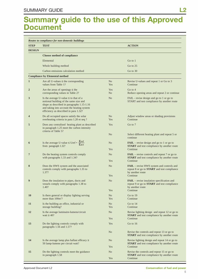
Routes to compliance for non-domestic buildings
STEP TEST ACTION
DESIGN
Choose method of compliance
Elemental Go to 1
Whole building method Go to 25
Carbon emissions calculation method Go to 30
Compliance by Elemental method
1 Are all U-values ≤ the corresponding No Revise U-values and repeat 1 or Go to 3values from Table 1? Yes Continue
2 Are the areas of openings ≤ the Yes Go to 4corresponding values in Table 2? No Reduce opening areas and repeat 2 or continue
3 Is the average U-value ≤ to that of a No FAIL - revise design and go to 1 or go to notional building of the same size and START and test compliance by another routeshape as described in paragraphs 1.15-1.16and taking into account the heating systemefficiency as described in para 1.32?
4 Do all occupied spaces satisfy the solar No Adjust window areas or shading provisionsoverheating criteria in para 1.20 et seq ? Yes Continue
5 Does any centralised heating plant as described Yes Go to 7in paragraph 1.25 meet the carbon intensity criteria of Table 5?
No Select different heating plant and repeat 5 or continue
6 Is the average U-value ≤ Uref • No FAIL – revise design and go to 1 or go tofrom paragraph 1.32? START and test compliance by another route
Yes Continue
7 Do the heating system controls comply No FAIL – revise controls and repeat 7 or go towith paragraphs 1.33 and 1.34? START and test compliance by another route
Yes Continue
8 Does the HWS system and the associated No FAIL – revise HWS system and controls andcontrols comply with paragraphs 1.35 to repeat 8 or go to START and test compliance 1.37? by another route
Yes Continue
9 Does the insulation to pipes, ducts and No FAIL – revise insulation specification and vessels comply with paragraphs 1.38 to repeat 9 or go to START and test compliance 1.40? by another route
Yes Continue
10 Is there general or display lighting serving No Go to 19more than 100m2? Yes Continue
11 Is the building an office, industrial or No Go to 14storage building? Yes Continue
12 Is the average luminaire-lumens/circuit No Revise lighting design and repeat 12 or go towatt ≥ 40? START and test compliance by another route
Yes Continue
13 Do the lighting controls comply with Yes Go to 16paragraphs 1.56 and 1.57?
No Revise the controls and repeat 13 or go toSTART and test compliance by another route
14 Is the average lamp plus ballast efficacy ≥ No Revise lighting design and repeat 14 or go to50 lamp-lumens per circuit watt? START and test compliance by another route
Yes Continue
15 Do the lighting controls meet the guidance No Revise the controls and repeat 15 or go toin paragraph 1.58 START and test compliance by another route
Yes Continue
εrefεact
Approved Document L2Conservation of fuel and power6
L2 SUMMARY GUIDE
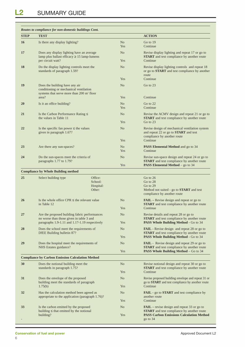
Routes to compliance for non-domestic buildings Cont.
STEP TEST ACTION
16 Is there any display lighting? No Go to 19Yes Continue
17 Does any display lighting have an average No Revise display lighting and repeat 17 or go tolamp plus ballast efficacy ≥ 15 lamp-lumens START and test compliance by another routeper circuit watt? Yes Continue
18 Do the display lighting controls meet the No Revise display lighting controls and repeat 18standards of paragraph 1.59? or go to START and test compliance by another
routeYes Continue
19 Does the building have any air No Go to 23conditioning or mechanical ventilation systems that serve more than 200 m2 floor area? Yes Continue
20 Is it an office building? No Go to 22Yes Continue
21 Is the Carbon Performance Rating ≤ No Revise the ACMV design and repeat 21 or go tothe values in Table 11 START and test compliance by another route
Yes Go to 23
22 Is the specific fan power ≤ the values No Revise design of mechanical ventilation systemgiven in paragraph 1.67? and repeat 22 or go to START and test
compliance by another routeYes Continue
23 Are there any sun-spaces? No PASS Elemental Method and go to 34Yes Continue
24 Do the sun-spaces meet the criteria of No Revise sun-space design and repeat 24 or go toparagraphs 1.77 to 1.79? START and test compliance by another route
Yes PASS Elemental Method – go to 34
Compliance by Whole Building method
25 Select building type Office: Go to 26School: Go to 28Hospital: Go to 29Other: Method not suited - go to START and test
compliance by another route
26 Is the whole office CPR ≤ the relevant value No FAIL – Revise design and repeat or go toin Table 12 START and test compliance by another route
Yes Continue
27 Are the proposed building fabric performances No Revise details and repeat 28 or go tono worse than those given in table 3 and START and test compliance by another routeparagraphs 1.9-1.11 and 1.17-1.19 respectively Yes PASS Whole Building Method - Go to 34
28 Does the school meet the requirements of No FAIL - Revise design and repeat 28 or go toDfEE Building bulletin 87? START and test compliance by another route
Yes PASS Whole Building Method - Go to 34
29 Does the hospital meet the requirements of No FAIL - Revise design and repeat 29 or go toNHS Estates guidance? START and test compliance by another route
Yes PASS Whole Building Method – Go to 34
Compliance by Carbon Emission Calculation Method
30 Does the notional building meet the No Revise notional design and repeat 30 or go to standards in paragraph 1.75? START and test compliance by another route
Yes Continue
31 Does the envelope of the proposed No Revise proposed building envelope and repeat 31 orbuilding meet the standards of paragraph go to START and test compliance by another route1.75(b) Yes Continue
32 Has the calculation method been agreed as No FAIL - go to START and test compliance by appropriate to the application (paragraph 1.76)? another route
Yes Continue
33 Is the carbon emitted by the proposed No FAIL – revise design and repeat 33 or go to building ≤ that emitted by the notional START and test compliance by another routebuilding? Yes PASS Carbon Emissions Calculation Method
- go to 34
Conservation of fuel and powerApproved Document L27
L2SUMMARY GUIDE
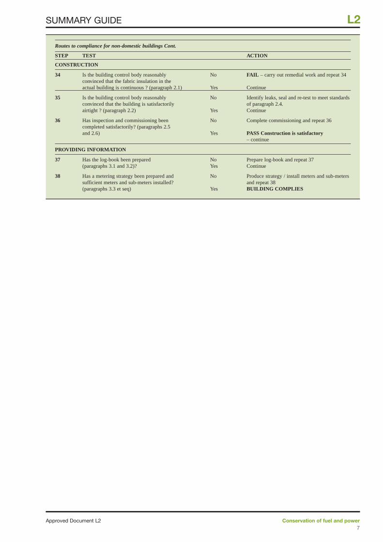
Routes to compliance for non-domestic buildings Cont.
STEP TEST ACTION
CONSTRUCTION
34 Is the building control body reasonably No FAIL – carry out remedial work and repeat 34convinced that the fabric insulation in the actual building is continuous ? (paragraph 2.1) Yes Continue
35 Is the building control body reasonably No Identify leaks, seal and re-test to meet standardsconvinced that the building is satisfactorily of paragraph 2.4.airtight ? (paragraph 2.2) Yes Continue
36 Has inspection and commissioning been No Complete commissioning and repeat 36completed satisfactorily? (paragraphs 2.5 and 2.6) Yes PASS Construction is satisfactory
– continue
PROVIDING INFORMATION
37 Has the log-book been prepared No Prepare log-book and repeat 37(paragraphs 3.1 and 3.2)? Yes Continue
38 Has a metering strategy been prepared and No Produce strategy / install meters and sub-meters sufficient meters and sub-meters installed? and repeat 38(paragraphs 3.3 et seq) Yes BUILDING COMPLIES
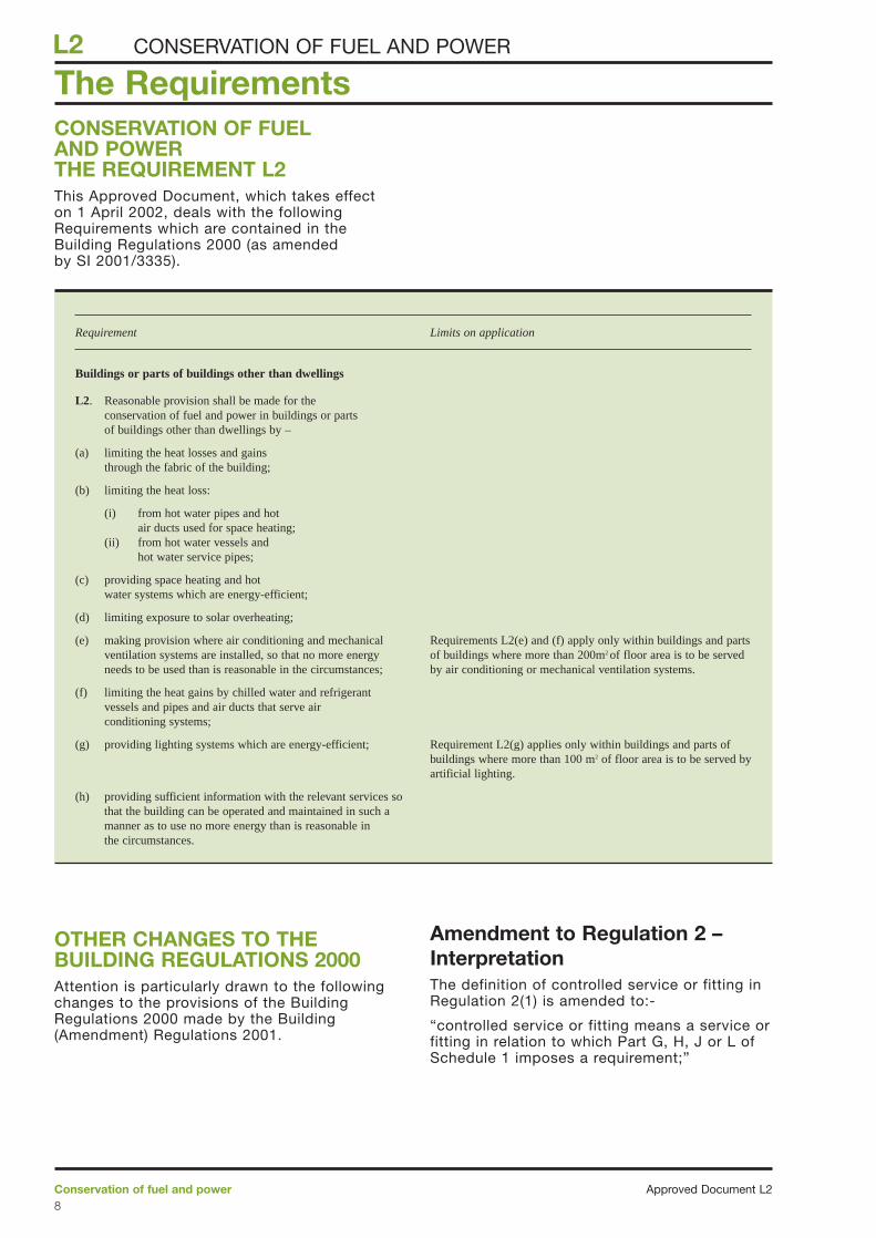
CONSERVATION OF FUELAND POWERTHE REQUIREMENT L2This Approved Document, which takes effecton 1 April 2002, deals with the followingRequirements which are contained in theBuilding Regulations 2000 (as amendedby SI 2001/3335).
OTHER CHANGES TO THEBUILDING REGULATIONS 2000Attention is particularly drawn to the followingchanges to the provisions of the BuildingRegulations 2000 made by the Building(Amendment) Regulations 2001.
Amendment to Regulation 2 –InterpretationThe definition of controlled service or fitting inRegulation 2(1) is amended to:-
“controlled service or fitting means a service orfitting in relation to which Part G, H, J or L ofSchedule 1 imposes a requirement;”
The Requirements
Approved Document L2Conservation of fuel and power8
L2 CONSERVATION OF FUEL AND POWER
Requirement Limits on application
Buildings or parts of buildings other than dwellings
L2. Reasonable provision shall be made for the conservation of fuel and power in buildings or partsof buildings other than dwellings by –
(a) limiting the heat losses and gains through the fabric of the building;
(b) limiting the heat loss:
(i) from hot water pipes and hot air ducts used for space heating;
(ii) from hot water vessels and hot water service pipes;
(c) providing space heating and hot water systems which are energy-efficient;
(d) limiting exposure to solar overheating;
(e) making provision where air conditioning and mechanical Requirements L2(e) and (f) apply only within buildings and parts ventilation systems are installed, so that no more energy of buildings where more than 200m2 of floor area is to be served needs to be used than is reasonable in the circumstances; by air conditioning or mechanical ventilation systems.
(f) limiting the heat gains by chilled water and refrigerantvessels and pipes and air ducts that serve air conditioning systems;
(g) providing lighting systems which are energy-efficient; Requirement L2(g) applies only within buildings and parts ofbuildings where more than 100 m2 of floor area is to be served byartificial lighting.
(h) providing sufficient information with the relevant services sothat the building can be operated and maintained in such amanner as to use no more energy than is reasonable inthe circumstances.
Amendments to Regulation 3 –Meaning of building workRegulation 3(1) is amended as follows:
“3(1) …
(b) subject to paragraph (1A), theprovision or extension of a controlledservice or fitting in or in connectionwith a building;”
New Regulation 18 –Testing of building workA new Regulation 18 is subtituted which says:-
“Testing of building work
The local authority may make such tests of anybuilding as may be necessary to establishwhether it complies with regulation 7 or any ofthe applicable requirements contained inSchedule 1.”
Conservation of fuel and powerApproved Document L29
L2CONSERVATION OF FUEL AND POWER
Performance0.1 In the Secretary of State's viewrequirement L2 (a) will be met by the provisionof energy efficiency measures which:
a) limit the heat loss through the roof, wall,floor, windows and doors etc by suitable meansof insulation, and where appropriate permit thebenefits of solar heat gains and more efficientheating systems to be taken into account; and
b) limit the heat gains in summer; and
c) limit heat losses (and gains whererelevant) through unnecessary air infiltration byproviding building fabric which is reasonablyairtight.
0.2 In the Secretary of State's viewrequirement L2 (b) will be met by limiting theheat loss from hot water pipes and hot airducts used for space heating and from hotwater vessels and hot water service pipes byapplying suitable thicknesses of insulationwhere such heat does not make an efficientcontribution to the space heating.
0.3 In the Secretary of State's viewrequirement L2 (c) will be met by the provisionof space heating and hot water systems withreasonably efficient equipment such as heatingappliances and hot water vessels whererelevant, and timing and temperature controls,and suitable energy consumption metering, thathave been appropriately commissioned suchthat the heating and hot water systems can beoperated effectively as regards theconservation of fuel and power.
0.4 In the Secretary of State’s viewrequirement L2 (d) will be met by theappropriate combination of passive measures,such as limiting the area of glazing which is notshaded and providing external building fabricthat limits and delays heat penetration, withactive measures, such as night ventilation, sothat the effects of solar heat gains are keptwithin limits that are reasonable in thecircumstances.
0.5 In the Secretary of State’s view, whenbuildings are proposed to be mechanicallyventilated or air conditioned, requirement L2 (e)will be met by:-
a) limiting the demands from within thebuilding for heating and cooling and circulationof air, water and refrigerants; and
b) providing reasonably efficient plant anddistribution systems, and timing, temperatureand flow controls, and suitable energyconsumption metering, that have beenappropriately commissioned.
0.6 In the Secretary of State's viewrequirement L2 (f) will be met by limiting theheat gains to chilled water and refrigerant
vessels and pipes and air ducts by applyingsuitable thicknesses of insulation includingvapour barriers.
0.7 In the Secretary of State's viewrequirement L2 (g) will be met by the provisionof lighting systems that where appropriate:
a) utilise energy-efficient lamps andluminaires, and
b) have suitable manual switching orautomatic switching, or both manual andautomatic switching controls, and
c) have suitable energy consumptionmetering, and
d) have been appropriately commissioned.
0.8 In the Secretary of State’s viewrequirement L2 (h) will be met by providinginformation, in a suitably concise andunderstandable form, and including the resultsof performance tests carried out during theworks, that shows how the building and itsrelevant building services can be operated andmaintained so that they use no more energythan is reasonable in the circumstances.
Introduction to the ProvisionsTechnical Risk
0.9 Guidance on avoiding technical risks (suchas rain penetration, condensation etc) whichmight arise from the application of energyconservation measures is given in BRE ReportNo 262: “Thermal Insulation: avoiding risks”,2002 Edition. As well as giving guidance onventilation for health, Approved Document Fcontains guidance on the provision ofventilation to reduce the risk of condensation inroof spaces. Approved Document J givesguidance on the safe accommodation ofcombustion systems including the ventilationrequirements for combustion and the properworking of flues. Approved Document E givesguidance on achieving satisfactory resistanceto the passage of sound. Guidance on somesatisfactory design details is given in therobust details publication 1.
Section 0: General guidance
Approved Document L2Conservation of fuel and power10
L2 GENERAL
1 Limiting thermal bridging and air leakage: Robustconstruction details for dwellings and similar buildings;TSO, 2001
Thermal conductivity and transmittance
0.10 Thermal conductivity (i.e. the lambda-value) of a material is a measure of the rate atwhich that material will pass heat and isexpressed in units of Watts per metre perdegree of temperature difference (W/mK).
0.11 Thermal transmittance (i.e. the U-value) isa measure of how much heat will pass throughone square metre of a structure when the airtemperatures on either side differ by onedegree. U-values are expressed in units ofWatts per square metre per degree oftemperature difference (W/m2K).
0.12 Exposed element means an elementexposed to the outside air (including asuspended floor over a ventilated orunventilated void, and elements so exposedindirectly via an unheated space), or anelement in the floor or basement in contactwith the ground. In the case of an elementexposed to the outside air via an unheatedspace (previously known as a “semi-exposedelement”) the U-value should be derived fromthe transmission heat loss coefficient2. Partywalls, separating two premises that canreasonably be assumed to be heated to thesame temperature, are assumed not to needthermal insulation.
0.13 In the absence of test information, thermalconductivities and thermal transmittances (U-values) may be taken from the tables in thisApproved Document or alternatively in the caseof U-values they may be calculated. However, iftest results for particular materials and makesof products obtained in accordance with aharmonised European Standard are availablethey should be used in preference.Measurements of thermal conductivity should
be made according to BS EN 126643, BS EN126674, or BS EN 129395. Measurements ofthermal transmittance should be madeaccording to BS EN ISO 89906 or, in the caseof windows and doors, BS EN ISO 12567-17.The size and configuration of windows fortesting or calculation should be representativeof those to be installed in the building, orconform to published guidelines on theconventions for calculating U-values8.
U-value reference tables
0.14 Appendix A contains tables of U-valuesand examples of their use, which provide asimple way to establish the amount ofinsulation needed to achieve a given U-valuefor some typical forms of construction. Theyyield cautious results that, in practice, areequal or better than the stated U values.However specific calculations whereproprietary insulation products are proposedmay indicate that somewhat less insulationcould be reasonable. The values in the tableshave been derived taking account of typicalthermal bridging where appropriate. AppendixA also contains tables of indicative U-valuesfor windows, doors and rooflights.
Calculation of U-values
0.15 U-values should calculated using themethods given in:
- for walls and roofs: BS EN ISO 69469
- for ground floors: BS EN ISO 1337010
- for windows and doors:BS EN ISO 10077-111 orprEN ISO 10077-212
- for basements: BS EN ISO 13370 or theBCA/NHBC Approved Document.13
Conservation of fuel and powerApproved Document L211
L2GENERAL
2 BS EN ISO 13789:1999 Thermal performance ofbuildings - Transmission heat loss coefficient -Calculation method
3 BS EN 12664:2001 Thermal performance of buildingmaterials and products – Determination of thermalresistance by means of guarded hot plate and heatflow meter methods – Dry and moist products of lowand medium thermal resistance
4 BS EN 12667:2000 Thermal performance of buildingmaterials and products – Determination of thermalresistance by means of guarded hot plate and heatflow meter methods – Products of high and mediumthermal resistance
5 BS EN 12939:2001 Thermal performance of buildingmaterials and products – Determination of thermalresistance by means of guarded hot plate and heatflow meter methods – Thick products of high andmedium thermal resistance
6 BS EN ISO 8990:1996 Thermal insulation –Determination of steady-state thermal transmissionproperties – Calibrated hot box
7 BS EN ISO 12567-1:2000 Thermal performance ofwindows and doors – Determination of thermaltransmittance by hot box method – Part 1: Completewindows and doors
8 Conventions for the calculation of U-values, BRE:expected publication date early 2002
9 BS EN ISO 6946:1997 Building components andbuilding elements – Thermal resistance and thermaltransmittance – Calculation method
10 BS EN ISO 13370:1998 Thermal performance ofbuildings – Heat transfer via the ground – Calculationmethods
11 BS EN ISO 10077-1:2000 Thermal performance ofwindows, doors and shutters – Calculation of thermaltransmittance – Part 1: Simplified methods
12 prEN ISO 10077-2: Thermal performance of windows,doors and shutters – Calculation of thermaltransmittance – Part 2: Numerical method for frames
13 Approved Document “Basements for dwellings”,ISBN 0-7210-1508-5, 1997
For building elements not covered by thesedocuments the following may be appropriatealternatives: BRE IP 5/9814 for curtain wallingthe CAB Guide15 or the methodology inCWCT guidance16,17, BRE guidance for lightsteel frame walls18, or finite element analysis inaccordance with BS EN ISO 10211-117 orBS EN ISO 10211-220 . BRE guidance onconventions for establishing U-values8 can befollowed. Some examples of U-valuecalculations are given in Appendix B andAppendix C gives data for ground floorsand basements.
0.16 Thermal conductivity values for commonbuilding materials can be obtained fromBS EN 1252421 or the CIBSE Guide SectionA322, but for ease of reference a table ofcommon materials is given in Appendix A. Forspecific insulation products, data should beobtained from the manufacturers.
0.17 When calculating U-values, the thermalbridging effects of, for instance, timber joists,structural and other framing, normal mortarbedding and window frames should generallybe taken into account using the proceduregiven in BS EN ISO 6946 (some examples aregiven in Appendix B). Thermal bridging can bedisregarded however where the difference inthermal resistance between the bridgingmaterial and the bridged material is less than0.1 m2K/W. For example normal mortar jointsneed not be taken into account in calculationsfor brickwork. Where, for example, wallscontain in-built meter cupboards, and ceilingscontain loft hatches , recessed light fittings,etc, area-weighted average U-values shouldbe calculated.
Roof window
0.18 A roof window is a window in the plane ofa pitched roof and may be considered as arooflight for the purposes of this ApprovedDocument.
Basis for calculating areas
0.19 The dimensions for the areas of walls,roofs and floors should be measured betweenfinished internal faces of the external elementsof the building including any projecting bays. Inthe case of roofs they should be measured inthe plane of the insulation. Floor areas shouldinclude non-useable space such as builders’ducts and stairwells.
Air permeability
0.20 Air permeability is the physical propertyused to quantify airtightness of building fabric.It measures the resistance of the buildingenvelope to inward or outward air permeation.It is defined as the average volume of air (incubic metres per hour) that passes through unitarea of the structure of the building envelope(in square metres) when subject to an internalto external pressure difference of 50 Pa. It is
expressed in units of cubic metres per hour,per square metre of envelope area, at apressure difference of 50 Pa. The envelopearea of the building is defined as the total areaof the floor, walls and roof separating theinterior volume (i.e. the conditioned space)from the outside environment.
Conversion between carbon and carbondioxide indices
0.21 To maintain consistency with theGovernment’s Climate Change Programme, theperformance targets in this ApprovedDocument are quoted in terms of kg of carbonrather than kg of carbon dioxide, or in energyterms such as GigaJoules or MegaWatt-hours.To convert from the carbon to carbon dioxidebasis multiply by the ratio of atomic weights(Carbon Dioxide 44 : Carbon 12). For example9 tonnes per square metre per year of carbonis equivalent to {9 x (44/12)} = 33 tonnes ofcarbon dioxide per square metre per year.
Approved Document L2Conservation of fuel and power12
L2 GENERAL
14 IP 5/98 Metal cladding: assessing thermalperformance, BRE, 1998
15 Guide to assessment of the thermal performance ofaluminium curtain wall framing, CAB, 1996
16 Guide to good practice for asessing glazing frameU-values, CWCT (1998, new edition in preperation).
17 Guide to good practice for assessing heat transfer andcondensation risk for a curtain wall, CWCT (1998, newedition in preperation).
18 U-value calculation procedure for light steel framewalls, BRE, to be published
19 BS EN ISO 10211-1:1996 Thermal bridges in buildingconstruction – Calculation of heat flows and surfacetemperatures – Part 1: General methods
20 BS EN ISO 10211-2:2001 Thermal bridges in buildingconstruction – Calculation of heat flows and surfacetemperatures – Part 2: Linear thermal bridges
21 BS EN 12524:2000 Building materials and products –Hygrothermal properties – Tabulated design values
22 CIBSE Guide A: Environmental design, Section A3:Thermal properties of building structures, CIBSE, 1999
Special casesLow levels of heating
0.22 Buildings or parts of buildings with lowlevels of heating or no heating do not requiremeasures to limit heat transfer through thefabric. The insulation properties of the fabriccontaining such spaces are chosen foroperational reasons and can be regarded asreasonable provision. Low levels of heatingmight be no more than 25W/m2, an examplebeing perhaps a warehouse where heating isintended to protect goods from condensationor frost, with higher temperatures providedonly around local work stations. A cold-storeis an example of a building where insulationproperties would be dictated byoperational needs.
Low levels of use
0.23 For buildings with low hours of use, lowerstandards for heating and lighting systemsmay be appropriate, but fabric insulationstandards should be no worse than theguidance in this Approved Document.Buildings used solely for worship at set timescould be one example where this paragraphwould be relevant.
Historic Buildings
0.24 Advice on the factors determining thecharacter of historic buildings is set out inPPG1523. Specific guidance on meeting therequirements of Part L when undertaking workin historic buildings is given in Section 4 of thisApproved Document.
Buildings constructed from sub-assemblies
0.25 Buildings constructed from sub-assemblies that are delivered newly made orselected from a stock are no different to anyother new building and must comply with allthe requirements in Schedule 1.
0.26 In some applications however, such asbuildings constructed to accommodateclassrooms, medical facilities, offices andstorage space to meet temporaryaccommodation needs, reasonable externalfabric provisions for the conservation of fueland power can vary depending on thecircumstances in the particular case.For example:-
a) A building created by dismantling,transporting and re-erecting on the samepremises the external fabric sub-assemblies ofan existing building would normally beconsidered to meet the requirement;
b) A building constructed from external fabricsub-assemblies obtained from other premisesor from a stock manufactured before 31December 2001, would normally be consideredto meet the requirement if the fabric thermalresistance or the prospective annual energy
use will be no worse than the relevantperformance standards given in the 1995edition of Approved Document L.
0.27 Enclosed and heated or cooled linksbetween such temporary accommodation,which may also be formed from sub-assemblies, should be insulated and madeairtight to the same standards as the buildingsthemselves.
0.28 Where heating and lighting are to beprovided in such temporary accommodation,the requirements may be satisfied in thefollowing ways although the extent of theprovisions will depend on the circumstances inthe particular case:-
a) heating and hot water systems:providing on/off, time and temperature controlsas indicated in Section 1 of this ApprovedDocument.
b) general and display lighting: providinggeneral lighting systems with lamp efficaciesthat are not less than those indicated inparagraph 1.48 and providing display lightingwith installed efficacies not less that thoseindicated in paragraphs 1.50-1.52.
Mixed use development0.29 When constructing buildings that haveparts used as dwellings as well as parts forother uses, account should be taken of theguidance in Approved Document L1.
Conservation of fuel and powerApproved Document L213
L2GENERAL
23 Planning and the historic environment, Planning PolicyGuidance PPG 15, DoE/DNH, September 1994. (InWales refer to Planning Guidance Wales PlanningPolicy First Revision 1999 and Welsh Office Circular61/96 Planning and Historic Environment: HistoricBuildings and Conservation Areas.)
General1.1 In order to achieve energy efficiency inpractice, the building and its services systemsshould be appropriately designed (Section 1)and constructed (Section 2). Information shouldalso be provided such that the performance ofthe building in use can be assessed (Section3). This Approved Document provides guidanceon meeting the requirements at each of theseimportant stages of procuring a building,whether it be a new building, an extension or arefurbishment project. More detailed guidanceon energy efficiency measures can be found inthe CIBSE Guide on Energy Efficiency inBuildings24.
1.2 When designing building servicesinstallations, provision should be made tofacilitate appropriate inspection andcommissioning (see paragraphs 2.5 – 2.6).
1.3 Specific guidance for work carried out onexisting buildings is given in Section 4.
1.4 In large complex buildings, it may besensible to consider the provisions for theconservation of fuel and power separately forthe different parts of the building in order toestablish the measures appropriate to eachpart.
1.5 Where alternative building servicessystems are provided (e.g. dual fuel boilers,and combined heat and power or heat pumpsystems paralleled by standby boiler capacity),then the building should meet the requirementsin each possible operating mode.
Alternative methods of showingcompliance1.6 Three methods are given fordemonstrating that reasonable provision hasbeen made for the conservation of fuel andpower. These different methods offer increasingdesign flexibility in return for greater demandsin terms of the extent of calculation required.However the overall aim is to achieve the samestandard in terms of carbon emissions. Themethods are:
a) an Elemental Method (paragraphs 1.7 –1.68). This method considers the performanceof each aspect of the building individually. Tocomply with the provisions of Part L, aminimum level of performance should beachieved in each of the elements. Someflexibility is provided for trading off betweendifferent elements of the construction, andbetween insulation standards and heatingsystem performance.
b) a Whole-Building Method (paragraphs1.69 - 1.73). This method considers theperformance of the whole building. For officebuildings, the heating, ventilation, air
conditioning and lighting systems should becapable of being operated such that they willemit no more carbon per square metre perannum than a benchmark based on the ECON19 data25. Alternative methods are alsoprovided for schools and hospitals.
c) a Carbon Emissions Calculation Method(paragraphs 1.74 – 1.76). This method alsoconsiders the performance of the wholebuilding, but can be applied to any buildingtype. To comply with the provisions of Part L,the annual carbon emissions from the buildingshould be no greater than that from a notionalbuilding that meets the compliance criteria ofthe Elemental Method. The carbon emissionsfrom the proposed building and the notionalbuilding need to be estimated using anappropriate calculation tool.
Elemental Method1.7 To show compliance following theElemental Method, the building envelope has toprovide certain minimum levels of insulation,and the various building services systems eachhave to meet defined minimum standards ofenergy efficiency as follows -
Standard U-values for construction elements
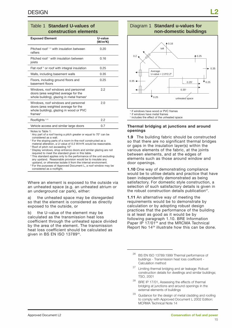
1.8 The requirement will be met if the thermalperformances of the construction elements areno worse than those listed in Table 1 (asillustrated in Diagram 1). One way of achievingthe U-values in Table 1 is by providinginsulation of a thickness estimated from theTables in Appendix A as illustrated in theexamples. An alternative for floors is to use thedata given in Appendix C.
Section 1: Design
Approved Document L2Conservation of fuel and power14
L2 DESIGN
24 CIBSE Guide, Energy efficiency in buildings, CIBSE,1998
25 Energy use in offices - Energy Consumption Guide 19,DETR, 1998
Where an element is exposed to the outside viaan unheated space (e.g. an unheated atrium oran underground car park), either:
a) the unheated space may be disregardedso that the element is considered as directlyexposed to the outside, or
b) the U-value of the element may becalculated as the transmission heat losscoefficient through the unheated space dividedby the area of the element. The transmissionheat loss coefficient should be calculated asgiven in BS EN ISO 1378926.
Thermal bridging at junctions and aroundopenings
1.9 The building fabric should be constructedso that there are no significant thermal bridgesor gaps in the insulation layer(s) within thevarious elements of the fabric, at the jointsbetween elements, and at the edges ofelements such as those around window anddoor openings.
1.10 One way of demonstrating compliancewould be to utilise details and practice that havebeen independently demonstrated as beingsatisfactory. For domestic style construction, aselection of such satisfactory details is given inthe robust construction details publication27.
1.11 An alternative way of meeting therequirements would be to demonstrate bycalculation or by adopting robust designpractices that the performance of the buildingis at least as good as it would be byfollowing paragraph 1.10. BRE InformationPaper IP 17/0128 and the MRCMA TechnicalReport No 1429 illustrate how this can be done.
Conservation of fuel and powerApproved Document L215
L2DESIGN
Table 1 Standard U-values ofconstruction elements
Exposed Element U-value(W/m2K)
Pitched roof 1, 2 with insulation between 0.20rafters
Pitched roof 1 with insulation between 0.16joists
Flat roof 3 or roof with integral insulation 0.25
Walls, including basement walls 0.35
Floors, including ground floors and 0.25basement floors
Windows, roof windows and personnel 2.2doors (area weighted average for the whole building), glazing in metal frames4
Windows, roof windows and personnel 2.0doors (area weighted average for the whole building), glazing in wood or PVC frames4
Rooflights 5, 6 2.2
Vehicle access and similar large doors 0.7
Notes to Table 1:1 Any part of a roof having a pitch greater or equal to 70° can be
considered as a wall.2 For the sloping parts of a room-in-the-roof constructed as a
material alteration, a U-value of 0.3 W/m2K would be reasonable.3 Roof of pitch not exceeding 10°4 Display windows, shop entrance doors and similar glazing are not
required to meet the standard given in this table.5 This standard applies only to the performance of the unit excluding
any upstand. Reasonable provision would be to insulate anyupstand, or otherwise isolate it from the internal environment.
6 For the purposes of Approved Document L, a roof window may beconsidered as a rooflight.
Diagram 1 Standard u-values for non-domestic buildings
loft
unheated space
0.35
0.2
0.16
0.25
0.35
0.250.25c
0.35c
0.25
AverageU-value = 2.0a/2.2b
26 BS EN ISO 13789:1999 Thermal performance ofbuildings - Transmission heat loss coefficient -Calculation method
27 Limiting thermal bridging and air leakage: Robustconstruction details for dwellings and similar buildings;TSO, 2001
28 BRE IP 17/01, Assessing the effects of thermalbridging at junctions and around openings in theexternal elements of buildings
29 Guidance for the design of metal cladding and roofingto comply with Approved Document L 2002 Edition:MCRMA Technical Note 14
a if windows have wood or PVC framesb if windows have metal framesc includes the effect of the unheated space
Maximum areas of windows, doors androoflights
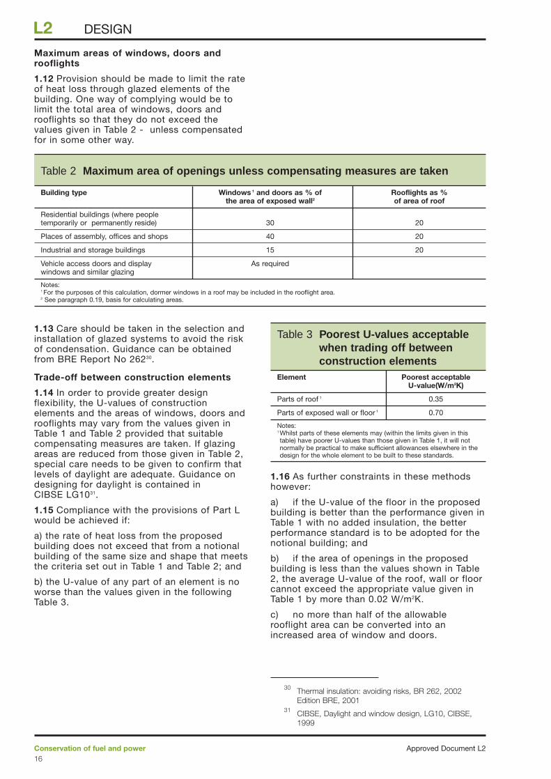
1.12 Provision should be made to limit the rateof heat loss through glazed elements of thebuilding. One way of complying would be tolimit the total area of windows, doors androoflights so that they do not exceed thevalues given in Table 2 - unless compensatedfor in some other way.
1.13 Care should be taken in the selection andinstallation of glazed systems to avoid the riskof condensation. Guidance can be obtainedfrom BRE Report No 26230.
Trade-off between construction elements
1.14 In order to provide greater designflexibility, the U-values of constructionelements and the areas of windows, doors androoflights may vary from the values given inTable 1 and Table 2 provided that suitablecompensating measures are taken. If glazingareas are reduced from those given in Table 2,special care needs to be given to confirm thatlevels of daylight are adequate. Guidance ondesigning for daylight is contained inCIBSE LG1031.
1.15 Compliance with the provisions of Part Lwould be achieved if:
a) the rate of heat loss from the proposedbuilding does not exceed that from a notionalbuilding of the same size and shape that meetsthe criteria set out in Table 1 and Table 2; and
b) the U-value of any part of an element is noworse than the values given in the followingTable 3.
1.16 As further constraints in these methodshowever:
a) if the U-value of the floor in the proposedbuilding is better than the performance given inTable 1 with no added insulation, the betterperformance standard is to be adopted for thenotional building; and
b) if the area of openings in the proposedbuilding is less than the values shown in Table2, the average U-value of the roof, wall or floorcannot exceed the appropriate value given inTable 1 by more than 0.02 W/m2K.
c) no more than half of the allowablerooflight area can be converted into anincreased area of window and doors.
Approved Document L2Conservation of fuel and power16
L2 DESIGN
Table 3 Poorest U-values acceptable when trading off between construction elements
Element Poorest acceptable U-value(W/m2K)
Parts of roof 1 0.35
Parts of exposed wall or floor 1 0.70
Notes:1 Whilst parts of these elements may (within the limits given in thistable) have poorer U-values than those given in Table 1, it will notnormally be practical to make sufficient allowances elsewhere in thedesign for the whole element to be built to these standards.
Table 2 Maximum area of openings unless compensating measures are taken
Building type Windows 1 and doors as % of Rooflights as %the area of exposed wall2 of area of roof
Residential buildings (where people temporarily or permanently reside) 30 20
Places of assembly, offices and shops 40 20
Industrial and storage buildings 15 20
Vehicle access doors and display As requiredwindows and similar glazing
Notes:1 For the purposes of this calculation, dormer windows in a roof may be included in the rooflight area.2 See paragraph 0.19, basis for calculating areas.
30 Thermal insulation: avoiding risks, BR 262, 2002Edition BRE, 2001
31 CIBSE, Daylight and window design, LG10, CIBSE,1999
Building air leakage standards
1.17 Buildings should be reasonably airtight toavoid unnecessary space heating and coolingdemand and to enable the effectiveperformance of ventilation systems.
1.18 Without prejudice to the need forcompliance with all the requirements inSchedule 1 however, the need to provide foradequate ventilation for health (Part F) andadequate air for combustion appliances (Part J)should particularly be taken into account.
1.19 A way of meeting the requirement wouldbe to incorporate sealing measures to achievethe performance standard given in paragraph2.4. Some ways of achieving satisfactoryairtightness include:
a) providing a reasonably continuous airbarrier in contact with the insulation layer overthe whole thermal envelope (includingseparating walls). Special care should be takenat junctions between elements and around doorand window openings. For domestic typeconstructions, some satisfactory design detailsand installation practice are described in therobust details publication25. Guidance for thedesign of metal cladding and roofing systemsto minimise air infiltration is given in theMCRMA Technical Report No 1427.
b) sealing gaps around service penetrations.
c) draught-proofing external doors andwindows.
Avoiding solar overheating
1.20 Buildings should be constructed suchthat:
a) those occupied spaces32 that rely onnatural ventilation should not overheat whensubject to a moderate level of internal heatgain and
b) those spaces that incorporate mechanicalventilation or cooling do not require excessivecooling plant capacity to maintain the desiredspace conditions.
1.21 Ways of meeting the requirement would bethrough:
a) the appropriate specification of glazing,and
b) the incorporation of passive measuressuch as shading (detailed guidance being givenin BRE Report No 36433), and
c) the use of exposed thermal capacitycombined with night ventilation (detailedguidance being given in GIR 3134).
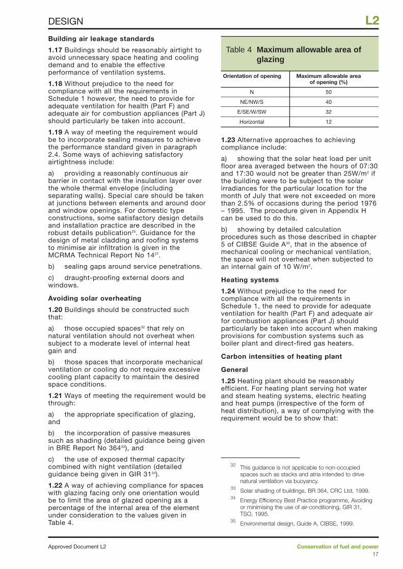
1.22 A way of achieving compliance for spaceswith glazing facing only one orientation wouldbe to limit the area of glazed opening as apercentage of the internal area of the elementunder consideration to the values given inTable 4.
1.23 Alternative approaches to achievingcompliance include:
a) showing that the solar heat load per unitfloor area averaged between the hours of 07:30and 17:30 would not be greater than 25W/m2 ifthe building were to be subject to the solarirradiances for the particular location for themonth of July that were not exceeded on morethan 2.5% of occasions during the period 1976– 1995. The procedure given in Appendix Hcan be used to do this.
b) showing by detailed calculationprocedures such as those described in chapter5 of CIBSE Guide A35, that in the absence ofmechanical cooling or mechanical ventilation,the space will not overheat when subjected toan internal gain of 10 W/m2.
Heating systems
1.24 Without prejudice to the need forcompliance with all the requirements inSchedule 1, the need to provide for adequateventilation for health (Part F) and adequate airfor combustion appliances (Part J) shouldparticularly be taken into account when makingprovisions for combustion systems such asboiler plant and direct-fired gas heaters.
Carbon intensities of heating plant
General
1.25 Heating plant should be reasonablyefficient. For heating plant serving hot waterand steam heating systems, electric heatingand heat pumps (irrespective of the form ofheat distribution), a way of complying with therequirement would be to show that:
Conservation of fuel and powerApproved Document L217
L2DESIGN
Table 4 Maximum allowable area ofglazing
Orientation of opening Maximum allowable area of opening (%)
N 50
NE/NW/S 40
E/SE/W/SW 32
Horizontal 12
32 This guidance is not applicable to non-occupiedspaces such as stacks and atria intended to drivenatural ventilation via buoyancy.
33 Solar shading of buildings, BR 364, CRC Ltd, 1999.34 Energy Efficiency Best Practice programme, Avoiding
or minimising the use of air-conditioning, GIR 31,TSO, 1995.
35 Environmental design, Guide A, CIBSE, 1999.
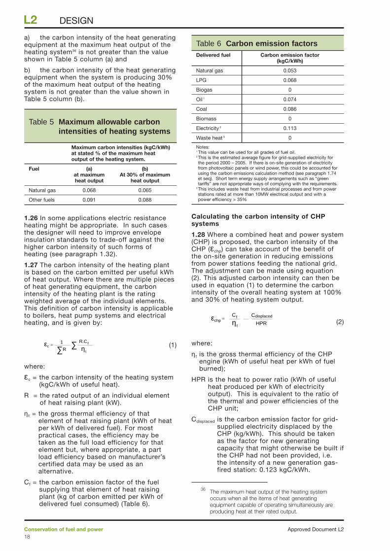
a) the carbon intensity of the heat generatingequipment at the maximum heat output of theheating system36 is not greater than the valueshown in Table 5 column (a) and
b) the carbon intensity of the heat generatingequipment when the system is producing 30%of the maximum heat output of the heatingsystem is not greater than the value shown inTable 5 column (b).
1.26 In some applications electric resistanceheating might be appropriate. In such casesthe designer will need to improve envelopeinsulation standards to trade-off against thehigher carbon intensity of such forms ofheating (see paragraph 1.32).
1.27 The carbon intensity of the heating plantis based on the carbon emitted per useful kWhof heat output. Where there are multiple piecesof heat generating equipment, the carbonintensity of the heating plant is the ratingweighted average of the individual elements.This definition of carbon intensity is applicableto boilers, heat pump systems and electricalheating, and is given by:
(1)
where:
εc = the carbon intensity of the heating system(kgC/kWh of useful heat).
R = the rated output of an individual elementof heat raising plant (kW).
η t = the gross thermal efficiency of thatelement of heat raising plant (kWh of heatper kWh of delivered fuel). For mostpractical cases, the efficiency may betaken as the full load efficiency for thatelement but, where appropriate, a partload efficiency based on manufacturer’scertified data may be used as analternative.
Cf = the carbon emission factor of the fuelsupplying that element of heat raisingplant (kg of carbon emitted per kWh ofdelivered fuel consumed) (Table 6).
Calculating the carbon intensity of CHPsystems
1.28 Where a combined heat and power system(CHP) is proposed, the carbon intensity of theCHP (εchp) can take account of the benefit ofthe on-site generation in reducing emissionsfrom power stations feeding the national grid.The adjustment can be made using equation(2). This adjusted carbon intensity can then beused in equation (1) to determine the carbonintensity of the overall heating system at 100%and 30% of heating system output.
(2)
where:
η t is the gross thermal efficiency of the CHPengine (kWh of useful heat per kWh of fuelburned);
HPR is the heat to power ratio (kWh of usefulheat produced per kWh of electricityoutput). This is equivalent to the ratio ofthe thermal and power efficiencies of theCHP unit;
Cdisplaced is the carbon emission factor for grid-supplied electricity displaced by theCHP (kg/kWh). This should be takenas the factor for new generatingcapacity that might otherwise be built ifthe CHP had not been provided, i.e.the intensity of a new generation gas-fired station: 0.123 kgC/kWh.
HPRε =chp η t
CdisplacedCf
∑ ∑ Rε = 1
c η t
R.Cf
Approved Document L2Conservation of fuel and power18
L2 DESIGN
Table 5 Maximum allowable carbonintensities of heating systems
Maximum carbon intensities (kgC/kWh) at stated % of the maximum heat output of the heating system.
Fuel (a) (b)at maximum At 30% of maximum heat output heat output
Natural gas 0.068 0.065
Other fuels 0.091 0.088
Table 6 Carbon emission factorsDelivered fuel Carbon emission factor
(kgC/kWh)
Natural gas 0.053
LPG 0.068
Biogas 0
Oil 1 0.074
Coal 0.086
Biomass 0
Electricity 2 0.113
Waste heat 3 0
Notes:1 This value can be used for all grades of fuel oil.2 This is the estimated average figure for grid-supplied electricity forthe period 2000 – 2005. If there is on-site generation of electricityfrom photovoltaic panels or wind power, this could be accounted forusing the carbon emissions calculation method (see paragraph 1.74et seq). Short term energy supply arrangements such as “greentariffs” are not appropriate ways of complying with the requirements.
3 This includes waste heat from industrial processes and from powerstations rated at more than 10MW electrical output and with apower efficiency > 35%
36 The maximum heat output of the heating systemoccurs when all the items of heat generatingequipment capable of operating simultaneously areproducing heat at their rated output.
1.29 Where the CHP has no facility for heatdumping, the gross thermal efficiency is simplythe CHP heat output divided by the energycontent of the fuel burned. Where the CHPincludes facilities for heat dumping, the grossthermal efficiency should be based on anestimate of the useful heat supplied to thebuilding, i.e. the heat output from the CHPminus the heat dumped. Certification underthe CHPQA37 scheme would be a way ofshowing that the gross thermal efficiency hasbeen estimated in a satisfactory way.
Calculating the carbon intensity ofcommunity heating
1.30 When calculating the carbon intensity ofthe heat supplied to the building by acommunity heating system, account should betaken of the performance of the whole system,(i.e. the distribution circuits, and all the heatgenerating plant including any CHP or wasteheat recovery) and the carbon emission factorsof the different fuels. Certification under theCHPQA37 scheme would be a way of showingthat the thermal and power efficiencies havebeen estimated in a satisfactory way.
Other methods of heating
1.31 In buildings such as factories, warehousesand workshops it can be more efficient toprovide local warm air or radiant heatingsystems. GPG 30338 provides guidance on theapplication of such systems.
Trade - off between construction elementsand heating system efficiency
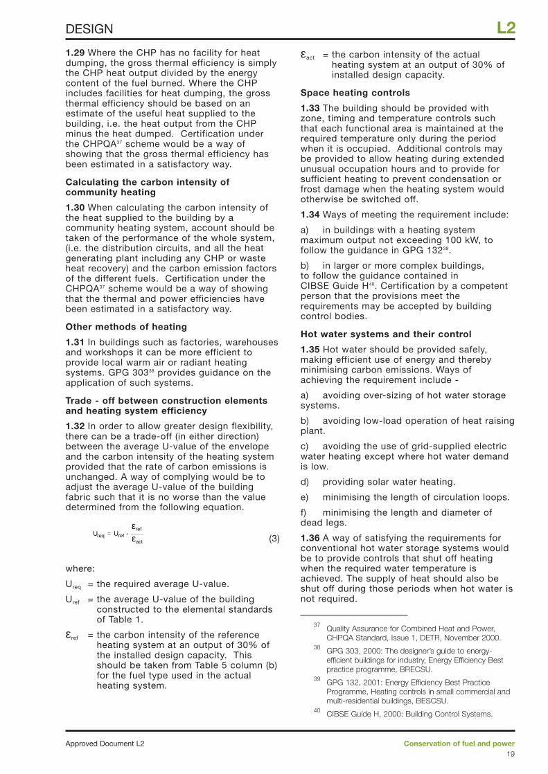
1.32 In order to allow greater design flexibility,there can be a trade-off (in either direction)between the average U-value of the envelopeand the carbon intensity of the heating systemprovided that the rate of carbon emissions isunchanged. A way of complying would be toadjust the average U-value of the buildingfabric such that it is no worse than the valuedetermined from the following equation.
(3)
where:
Ureq = the required average U-value.
Uref = the average U-value of the buildingconstructed to the elemental standardsof Table 1.
εref = the carbon intensity of the referenceheating system at an output of 30% ofthe installed design capacity. Thisshould be taken from Table 5 column (b)for the fuel type used in the actualheating system.
εact = the carbon intensity of the actualheating system at an output of 30% ofinstalled design capacity.
Space heating controls
1.33 The building should be provided withzone, timing and temperature controls suchthat each functional area is maintained at therequired temperature only during the periodwhen it is occupied. Additional controls maybe provided to allow heating during extendedunusual occupation hours and to provide forsufficient heating to prevent condensation orfrost damage when the heating system wouldotherwise be switched off.
1.34 Ways of meeting the requirement include:
a) in buildings with a heating systemmaximum output not exceeding 100 kW, tofollow the guidance in GPG 13239.
b) in larger or more complex buildings,to follow the guidance contained inCIBSE Guide H40. Certification by a competentperson that the provisions meet therequirements may be accepted by buildingcontrol bodies.
Hot water systems and their control
1.35 Hot water should be provided safely,making efficient use of energy and therebyminimising carbon emissions. Ways ofachieving the requirement include -
a) avoiding over-sizing of hot water storagesystems.
b) avoiding low-load operation of heat raisingplant.
c) avoiding the use of grid-supplied electricwater heating except where hot water demandis low.
d) providing solar water heating.
e) minimising the length of circulation loops.
f) minimising the length and diameter ofdead legs.
1.36 A way of satisfying the requirements forconventional hot water storage systems wouldbe to provide controls that shut off heatingwhen the required water temperature isachieved. The supply of heat should also beshut off during those periods when hot water isnot required.
U =req Uref
εref
εact
.
Conservation of fuel and powerApproved Document L219
L2DESIGN
37 Quality Assurance for Combined Heat and Power,CHPQA Standard, Issue 1, DETR, November 2000.
38 GPG 303, 2000: The designer’s guide to energy-efficient buildings for industry, Energy Efficiency Bestpractice programme, BRECSU.
39 GPG 132, 2001: Energy Efficiency Best PracticeProgramme, Heating controls in small commercial andmulti-residential buildings, BESCSU.
40 CIBSE Guide H, 2000: Building Control Systems.
1.37 Ways of meeting the requirement include:-
a) in small buildings, following the guidancein GPG 13239.
b) in larger, more complex buildings or foralternative systems (e.g. solar hot waterheating), following the guidance contained inCIBSE Guide H40. Certification by a competentperson that the provisions meet therequirements may be accepted by buildingcontrol bodies.
Insulation of pipes, ducts and vessels
Limit of application:
1.38 This section only applies to pipework,ductwork and vessels for the provision ofspace heating, space cooling (including chilledwater and refrigerant pipework) and hot watersupply for normal occupation. Pipework,ductwork and vessels for process use areoutside the scope of the Building Regulations.
Meeting the requirement
1.39 A way of meeting the requirement wouldbe to apply insulation to the standards requiredin BS 542241 to all pipework, ductwork andstorage vessels. The requirement for storagevessels should be taken as that given inBS 5422 for flat surfaces.
1.40 Insulation would not be necessary forcompliance with Part L if the heat flow throughthe walls of the pipe, duct or vessel is alwaysuseful in conditioning the surrounding spacewhen fluid is flowing through the pipe or duct,or is being stored in the vessel in question.However, it may be prudent to provide it tofacilitate control stability.
Lighting efficiency standards
1.41 Lighting systems should be reasonablyefficient and make effective use of daylightwhere appropriate.
1.42 For the purposes of Approved Document Lcircuit-watts means the power consumed inlighting circuits by lamps and their associatedcontrol gear and power factor correctionequipment.
General lighting efficacy in office, industrialand storage buildings
1.43 Electric lighting systems serving thesebuildings should be provided with reasonablyefficient lamp/luminaire combinations. A way ofmeeting the requirements would be to providelighting with an initial efficacy averaged overthe whole building of not less than 40luminaire-lumens/circuit-watt. This allowsconsiderable design flexibility to vary the lightoutput ratio of the luminaire, the luminousefficacy of the lamp or the efficiency of thecontrol gear.
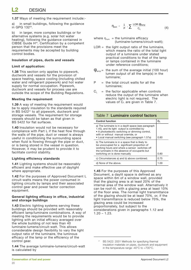
1.44 The average luminaire-lumens/circuit-wattis calculated by
(4)
where η lum = the luminaire efficacy (luminaire-lumens/circuit-watt);
LOR = the light output ratio of the luminaire,which means the ratio of the total lightoutput of a luminaire under statedpractical conditions to that of the lampor lamps contained in the luminaireunder reference conditions;
φlamp = the sum of the average initial (100 hour)lumen output of all the lamp(s) in theluminaire;
P = the total circuit watts for all theluminaires;
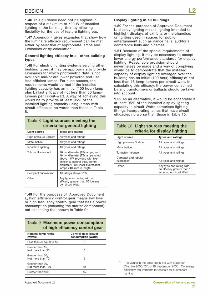
CL = the factor applicable when controlsreduce the output of the luminaire whenelectric light is not required. Thevalues of CL are given in Table 7.
1.45 For the purposes of this ApprovedDocument, a daylit space is defined as anyspace within 6m of a window wall, providedthat the glazing area is at least 20% of theinternal area of the window wall. Alternatively itcan be roof-lit, with a glazing area at least 10%of the floor area. The normal light transmittanceof the glazing should be at least 70%, or, if thelight transmittance is reduced below 70%, theglazing area could be increasedproportionately, but subject to theconsiderations given in paragraphs 1.12 and1.20 – 1.23.
∑ Pη = 1
lumCL
LOR. lampφ.
Approved Document L2Conservation of fuel and power20
L2 DESIGN
Table 7 Luminaire control factorsControl function CL
a) The luminaire is in a daylit space (see paragraph 1.45), and its light output is controlled by • A photoelectric switching or dimming control, with or without manual override, or• Local manual switching (see paragraph 1.57a) 0.80
b) The luminaire is in a space that is likely to be unoccupied for a significant proportion of working hours and where a sensor switches off the luminaire in the absence of occupants but switching on is done manually 0.80
c) Circumstances a) and b) above combined. 0.75
d) None of the above. 1.00
41 BS 5422: 2001 Methods for specifying thermalinsulation materials on pipes, ductwork and equipmentin the temperature range -40°C to +700°C.
1.46 This guidance need not be applied inrespect of a maximum of 500 W of installedlighting in the building, thereby allowingflexibility for the use of feature lighting etc.
1.47 Appendix F gives examples that show howthe luminaire efficacy requirement can be meteither by selection of appropriate lamps andluminaires or by calculation.
General lighting efficacy in all other buildingtypes
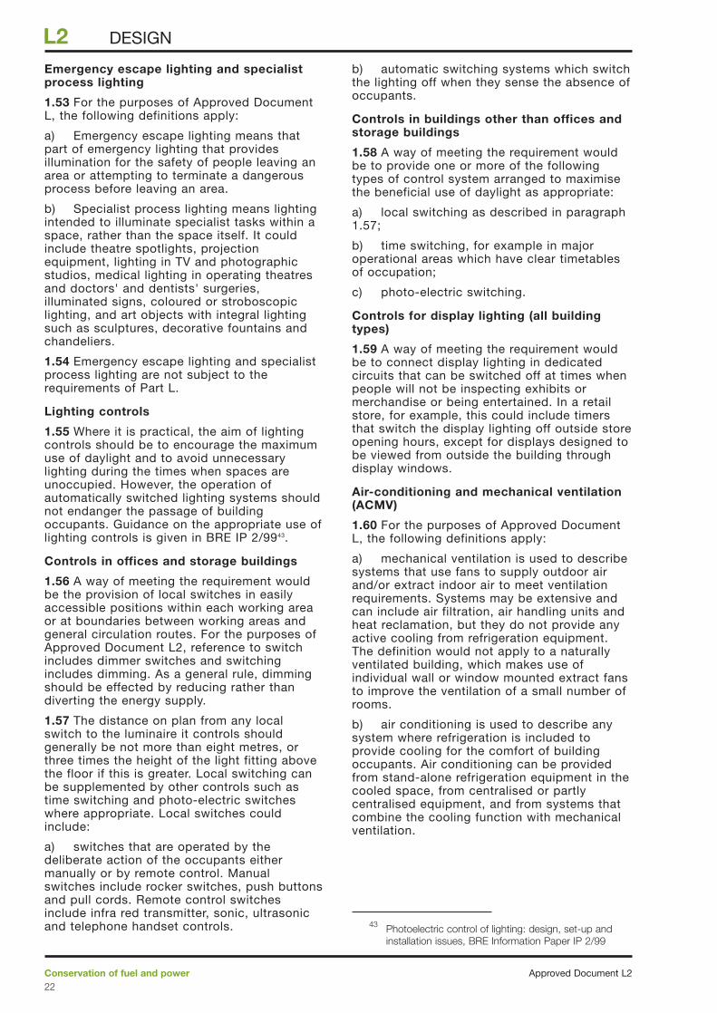
1.48 For electric lighting systems serving otherbuilding types, it may be appropriate to provideluminaires for which photometric data is notavailable and/or are lower powered and useless efficient lamps. For such spaces, therequirements would be met if the installedlighting capacity has an initial (100 hour) lampplus ballast efficacy of not less than 50 lamp-lumens per circuit-watt. A way of achieving thiswould be to provide at least 95% of theinstalled lighting capacity using lamps withcircuit efficacies no worse than those in Table8.
1.49 For the purposes of Approved DocumentL, high efficiency control gear means low lossor high frequency control gear that has a powerconsumption (including the starter component)not exceeding that shown in Table 942.
Display lighting in all buildings
1.50 For the purposes of Approved DocumentL, display lighting means lighting intended tohighlight displays of exhibits or merchandise,or lighting used in spaces for publicentertainment such as dance halls, auditoria,conference halls and cinemas.
1.51 Because of the special requirements ofdisplay lighting, it may be necessary to acceptlower energy performance standards for displaylighting. Reasonable provision shouldnevertheless be made and a way of complyingwould be to demonstrate that the installedcapacity of display lighting averaged over thebuilding has an initial (100 hour) efficacy of notless than 15 lamp-lumens per circuit-watt. Incalculating this efficacy, the power consumedby any transformers or ballasts should be takeninto account.
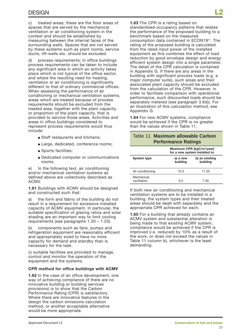
1.52 As an alternative, it would be acceptable ifat least 95% of the installed display lightingcapacity in circuit-Watts comprises lightingfittings incorporating lamps that have circuitefficacies no worse than those in Table 10.
Conservation of fuel and powerApproved Document L221
L2DESIGN
Table 8 Light sources meeting the criteria for general lighting
Light source Types and ratings
High pressure Sodium All types and ratings
Metal halide All types and ratings
Induction lighting All types and ratings
Tubular fluorescent 26mm diameter (T8) lamps, and 16mm diameter (T5) lamps rated above 11W, provided with high efficiency control gear. 38mm diameter (T12) linear fluorescent lamps 2400mm in length
Compact fluorescent All ratings above 11W
Other Any type and rating with an efficacy greater than 50 lumens per circuit Watt.
Table 9 Maximum power consumptionof high efficiency control gear
Nominal lamp rating Control gear power(Watts) consumption (Watts)
Less than or equal to 15 6
Greater than 15, Not more than 50 8
Greater than 50, Not more than 70 9
Greater than 70, Not more than 100 12
Greater than 100 15
Table 10 Light sources meeting thecriteria for display lighting
Light source Types and ratings
High pressure Sodium All types and ratings
Metal halide All types and ratings
Tungsten halogen All types and ratings
Compact and tubular fluorescent All types and ratings
Other Any type and rating with an efficacy greater than 15lumens per circuit Watt.
42 The values in the table are in line with EuropeanDirective 2000/55/EC 18 September 2000 : On energyefficiency requirements for ballasts for fluorescentlighting
Emergency escape lighting and specialistprocess lighting
1.53 For the purposes of Approved DocumentL, the following definitions apply:
a) Emergency escape lighting means thatpart of emergency lighting that providesillumination for the safety of people leaving anarea or attempting to terminate a dangerousprocess before leaving an area.
b) Specialist process lighting means lightingintended to illuminate specialist tasks within aspace, rather than the space itself. It couldinclude theatre spotlights, projectionequipment, lighting in TV and photographicstudios, medical lighting in operating theatresand doctors' and dentists' surgeries,illuminated signs, coloured or stroboscopiclighting, and art objects with integral lightingsuch as sculptures, decorative fountains andchandeliers.
1.54 Emergency escape lighting and specialistprocess lighting are not subject to therequirements of Part L.
Lighting controls
1.55 Where it is practical, the aim of lightingcontrols should be to encourage the maximumuse of daylight and to avoid unnecessarylighting during the times when spaces areunoccupied. However, the operation ofautomatically switched lighting systems shouldnot endanger the passage of buildingoccupants. Guidance on the appropriate use oflighting controls is given in BRE IP 2/9943.
Controls in offices and storage buildings
1.56 A way of meeting the requirement wouldbe the provision of local switches in easilyaccessible positions within each working areaor at boundaries between working areas andgeneral circulation routes. For the purposes ofApproved Document L2, reference to switchincludes dimmer switches and switchingincludes dimming. As a general rule, dimmingshould be effected by reducing rather thandiverting the energy supply.
1.57 The distance on plan from any localswitch to the luminaire it controls shouldgenerally be not more than eight metres, orthree times the height of the light fitting abovethe floor if this is greater. Local switching canbe supplemented by other controls such astime switching and photo-electric switcheswhere appropriate. Local switches couldinclude:
a) switches that are operated by thedeliberate action of the occupants eithermanually or by remote control. Manualswitches include rocker switches, push buttonsand pull cords. Remote control switchesinclude infra red transmitter, sonic, ultrasonicand telephone handset controls.
b) automatic switching systems which switchthe lighting off when they sense the absence ofoccupants.
Controls in buildings other than offices andstorage buildings
1.58 A way of meeting the requirement wouldbe to provide one or more of the followingtypes of control system arranged to maximisethe beneficial use of daylight as appropriate:
a) local switching as described in paragraph1.57;
b) time switching, for example in majoroperational areas which have clear timetablesof occupation;
c) photo-electric switching.
Controls for display lighting (all buildingtypes)
1.59 A way of meeting the requirement wouldbe to connect display lighting in dedicatedcircuits that can be switched off at times whenpeople will not be inspecting exhibits ormerchandise or being entertained. In a retailstore, for example, this could include timersthat switch the display lighting off outside storeopening hours, except for displays designed tobe viewed from outside the building throughdisplay windows.
Air-conditioning and mechanical ventilation(ACMV)
1.60 For the purposes of Approved DocumentL, the following definitions apply:
a) mechanical ventilation is used to describesystems that use fans to supply outdoor airand/or extract indoor air to meet ventilationrequirements. Systems may be extensive andcan include air filtration, air handling units andheat reclamation, but they do not provide anyactive cooling from refrigeration equipment.The definition would not apply to a naturallyventilated building, which makes use ofindividual wall or window mounted extract fansto improve the ventilation of a small number ofrooms.
b) air conditioning is used to describe anysystem where refrigeration is included toprovide cooling for the comfort of buildingoccupants. Air conditioning can be providedfrom stand-alone refrigeration equipment in thecooled space, from centralised or partlycentralised equipment, and from systems thatcombine the cooling function with mechanicalventilation.
Approved Document L2Conservation of fuel and power22
L2 DESIGN
43 Photoelectric control of lighting: design, set-up andinstallation issues, BRE Information Paper IP 2/99
c) treated areas; these are the floor areas ofspaces that are served by the mechanicalventilation or air conditioning system in thecontext and should be established bymeasuring between the internal faces of thesurrounding walls. Spaces that are not servedby these systems such as plant rooms, serviceducts, lift-wells etc. should be excluded.
d) process requirements; in office buildingsprocess requirements can be taken to includeany significant area in which an activity takesplace which is not typical of the office sector,and where the resulting need for heating,ventilation or air conditioning is significantlydifferent to that of ordinary commercial offices.When assessing the performance of airconditioning or mechanical ventilation systems,areas which are treated because of processrequirements should be excluded from thetreated area, together with the plant capacity,or proportion of the plant capacity, that isprovided to service those areas. Activities andareas in office buildings considered torepresent process requirements would thusinclude:
● Staff restaurants and kitchens;
● Large, dedicated, conference rooms;
● Sports facilities;
● Dedicated computer or communicationsrooms.
e) In the following text, air conditioningand/or mechanical ventilation systems asdefined above are collectively described asACMV.
1.61 Buildings with ACMV should be designedand constructed such that:
a) the form and fabric of the building do notresult in a requirement for excessive installedcapacity of ACMV equipment. In particular, thesuitable specification of glazing ratios and solarshading are an important way to limit coolingrequirements (see paragraphs 1.20 – 1.23).
b) components such as fans, pumps andrefrigeration equipment are reasonably efficientand appropriately sized to have no morecapacity for demand and standby than isnecessary for the task.
c) suitable facilities are provided to manage,control and monitor the operation of theequipment and the systems.
CPR method for office buildings with ACMV
1.62 In the case of an office development, oneway of achieving compliance (if there are noinnovative building or building servicesprovisions) is to show that the CarbonPerformance Rating (CPR) is satisfactory.Where there are innovative features in thedesign the carbon emissions calculationmethod, or another acceptable alternativewould be more appropriate.
1.63 The CPR is a rating based onstandardised occupancy patterns that relatesthe performance of the proposed building to abenchmark based on the measuredconsumption data contained in ECON1923. Therating of the proposed building is calculatedfrom the rated input power of the installedequipment as this combines the effect of loadreduction by good envelope design and energyefficient system design into a single parameter.The detail of the CPR calculation is containedin Appendix G. If there are any areas in thebuilding with significant process loads (e.g. amajor computer suite), such areas and theirassociated plant capacity should be excludedfrom the calculation of the CPR. However, inorder to facilitate comparison with operationalperformance, such discounted loads should beseparately metered (see paragraph 3.6d)). Foran illustration of this calculation method, seeAppendix G.
1.64 For new ACMV systems, compliancewould be achieved if the CPR is no greaterthan the values shown in Table 11.
If both new air conditioning and mechanicalventilation systems are to be installed in abuilding, the system types and their treatedareas should be dealt with separately and theappropriate CPR achieved for each.
1.65 For a building that already contains anACMV system and substantial alteration isbeing made to that existing ACMV system,compliance would be achieved if the CPR isimproved (i.e. reduced) by 10% as a result ofthe work, or does not exceed the values inTable 11 column b), whichever is the leastdemanding.
Conservation of fuel and powerApproved Document L223
L2DESIGN
Table 11 Maximum allowable CarbonPerformance Ratings
Maximum CPR (kgC/m2/year) for a new system installed in:
System type a) a new b) an existingbuilding building
Air conditioning 10.3 11.35
Mechanical ventilation 6.5 7.35
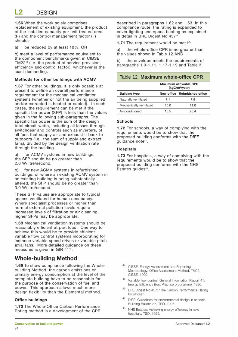
1.66 When the work solely comprisesreplacement of existing equipment, the productof the installed capacity per unit treated area(P) and the control management factor (F)should:-
a) be reduced by at least 10%, OR
b) meet a level of performance equivalent tothe component benchmarks given in CIBSETM2244 (i.e. the product of service provision,efficiency and control factor), whichever is theleast demanding.
Methods for other buildings with ACMV
1.67 For other buildings, it is only possible atpresent to define an overall performancerequirement for the mechanical ventilationsystems (whether or not the air being suppliedand/or extracted is heated or cooled). In suchcases, the requirement can be met if thespecific fan power (SFP) is less than the valuesgiven in the following sub-paragraphs. Thespecific fan power is the sum of the designtotal circuit-watts, including all losses throughswitchgear and controls such as inverters, ofall fans that supply air and exhaust it back tooutdoors (i.e., the sum of supply and extractfans), divided by the design ventilation ratethrough the building.
a) for ACMV systems in new buildings,the SFP should be no greater than2.0 W/litre/second.
b) for new ACMV systems in refurbishedbuildings, or where an existing ACMV system inan existing building is being substantiallyaltered, the SFP should be no greater than3.0 W/litre/second.
These SFP values are appropriate to typicalspaces ventilated for human occupancy.Where specialist processes or higher thannormal external pollution levels requireincreased levels of filtration or air cleaning,higher SFPs may be appropriate.
1.68 Mechanical ventilation systems should bereasonably efficient at part load. One way toachieve this would be to provide efficientvariable flow control systems incorporating forinstance variable speed drives or variable pitchaxial fans. More detailed guidance on thesemeasures is given in GIR 4145.
Whole-building Method1.69 To show compliance following the Whole-building Method, the carbon emissions orprimary energy consumption at the level of thecomplete building have to be reasonable forthe purpose of the conservation of fuel andpower. This approach allows much moredesign flexibility than the Elemental method.
Office buildings
1.70 The Whole-Office Carbon PerformanceRating method is a development of the CPR
described in paragraphs 1.62 and 1.63. In thiscompliance route, the rating is expanded tocover lighting and space heating as explainedin detail in BRE Digest No 45746.
1.71 The requirement would be met if:
a) the whole-office CPR is no greater thanthe values shown in Table 12 AND
b) the envelope meets the requirements ofparagraphs 1.9-1.11, 1.17-1.19 and Table 3.
Schools
1.72 For schools, a way of complying with therequirements would be to show that theproposed building conforms with the DfEEguidance note47.
Hospitals
1.73 For hospitals, a way of complying with therequirements would be to show that theproposed building conforms with the NHSEstates guides48.
Approved Document L2Conservation of fuel and power24
L2 DESIGN
Table 12 Maximum whole-office CPRMaximum allowable CPR
(kgC/m2/year)
Building type New office Refurbished office
Naturally ventilated 7.1 7.8
Mechanically ventilated 10.0 11.0
Air-conditioned 18.5 20.4
44 CIBSE, Energy Assessment and ReportingMethodology: Office Assessment Method, TM22,CIBSE, 1999.
45 Variable flow control, General Information Report 41,Energy Efficiency Best Practice programme, 1996.
46 BRE Digest No 457: “The Carbon Performance Ratingfor offices”.
47 DfEE, Guidelines for environmental design in schools,Building Bulletin 87, TSO, 1997.
48 NHS Estates: Achieving energy efficiency in newhospitals, TSO, 1994.
Carbon Emissions CalculationMethod1.74 To show compliance using the CarbonEmissions Calculation Method, the calculatedannual carbon emissions of the proposedbuilding should be no greater than those from anotional building of the same size and shapedesigned to comply with the Elemental Method.This approach allows more flexible design ofthe building, taking advantage of any validenergy conservation measure and takingaccount of useful solar and internal heat gains.
1.75 The following constraints should howeverbe applied:-
a) when establishing the parameters of thenotional building, the constraint on floorU-value in paragraph 1.16a) should be applied,and
b) the proposed building fabric and airleakage performances should be no worse thanthose given in Table 3 and paragraphs 1.9-1.11and 1.17-1.19 respectively.
1.76 The calculations should be carried outusing an acceptable method. The method maybe acceptable to building control bodies if:-
a) it has been approved by a relevantauthority responsible for issuing professionalguidance, or
b) it has been accepted by the organisationresponsible for the work as having satisfiedtheir in-house quality assurance procedures.This could be demonstrated by submitting withthe calculations a completed copy ofAppendix B (Checklist for choosing BEEMsoftware) of AM1149, showing that the softwareused is appropriate for the purpose to which ithas been applied.
Conservatories, atria and similarsun-spaces1.77 For the purposes of section 1 of ApprovedDocument L2, sun-space (which includesconservatories and atria) means a building orpart of a building having not less than three-quarters of the area of its roof and not lessthan half the area of its external walls (if any)made of translucent material.
1.78 When a sun-space is attached to and builtas part of a new building:
a) where there is no separation between thesun-space and the building, the sun-spaceshould be treated as an integral part of thebuilding;
b) where there is separation between thesun-space and the building, energy savings canbe achieved if the sun-space is not heated ormechanically cooled. If fixed heating ormechanical cooling installations are proposed,
however, they should have their own separatetemperature and on/off controls.
1.79 When a sun-space is attached to anexisting building and an opening is enlarged ornewly created as a material alteration,reasonable provision should be made to enablethe heat loss from, or the summer solar heatgain to, the building to be limited. Ways ofmeeting the requirement would be:
a) to retain the existing separation where theopening is not to be enlarged; or
b) to provide separation as, or equivalent to,windows and doors having the average U-valuegiven in Table 1.
1.80 For the purposes of this ApprovedDocument, separation between a building anda sun-space means:
a) separating walls and floors that areinsulated to at least the same degree as theexposed walls and floors;
b) separating windows and doors with thesame U-value and draught-proofing provisionsas the exposed windows and doors elsewherein the building.
1.81 Attention is drawn to the safetyrequirements of Part N of the BuildingRegulations regarding glazing materials andprotection.
Conservation of fuel and powerApproved Document L225
L2DESIGN
49 CIBSE AM11, 1998: Building Energy andEnvironmental Modelling.
Building FabricContinuity of insulation
2.1 To avoid excessive thermal bridging,appropriate design details and fixings shouldbe used (see paragraph 1.9). Responsibility forachieving compliance with the requirements ofPart L rests with the person carrying out thework. In the case of new buildings, that“person” will usually be, e.g., a developer ormain contractor who has carried out the worksubject to Part L, directly or by engaging asubcontractor. The person responsible forachieving compliance should (if suitablyqualified) provide a certificate or declarationthat the provisions meet the requirements ofPart L2(a); or they should obtain a certificate ordeclaration to that effect from a suitablyqualified person. Such certificates ordeclarations would state:
a) that appropriate design details andbuilding techniques have been used and thatthe work has been carried out in ways that canbe expected to achieve reasonable conformitywith the specifications that have beenapproved for the purposes of compliance withPart L2; or
b) that infra-red thermography inspectionshave shown that the insulation is reasonablycontinuous over the whole visible envelope.BRE Report 17650 gives guidance on the use ofthermography for building surveys.
Airtightness
2.2 Air barriers should be installed to minimiseair infiltration through the building fabric (seeparagraph 1.19). In this case too, certificates ordeclarations should be provided or obtained bythe person carrying out the work, stating:
a) for buildings of any size, that the resultsof air leakage tests carried out accordance withCIBSE TM 2351 are satisfactory; or
b) alternatively for buildings of less than1000m2 gross floor area, that appropriatedesign details and building techniques havebeen used, and that the work has been carriedout in ways that can be expected to achievereasonable conformity with the specificationsthat have been approved for the purposes ofcompliance with Part L2.
Certificates and Testing
2.3 Certificates or declarations such as thosementioned in paragraphs 2.1 and 2.2 may beaccepted by building control bodies asevidence of compliance. The building controlbody will, however, wish to establish, inadvance of the work, that the person who willbe giving the certificates or declarations issuitably qualified.
2.4 If using the CIBSE TM 23 pressure testprocedures as the means of showingcompliance:-
a) With effect from 1 October 2003,reasonable provision would be test resultsshowing that the air permeability (seeparagraph 0.20) does not exceed 10m3/h/m2 atan applied pressure difference of 50 Pa.
b) In the period up to and 30 September2003, reasonable provision in the event thatinitial test results are unsatisfactory would bethe results of further tests carried out afterappropriate remedial work showing:-
i) an improvement of 75% of the differencebetween the initial test result and the targetstandard of 10 m3/h/m2 at 50 Pa; OR, if lessdemanding
ii) a performance no worse than 11.5 m3/h/m2
at 50 Pa.
Inspection and Commissioning ofthe Building Services Systems2.5 In Part L2, in the context of buildingservices systems, ‘providing’ and ‘makingprovision’ should be taken as including, whererelevant, inspection and commissioning withmeanings as described below:
a) Inspection of building services systemsmeans establishing at completion ofinstallation that the specified and approvedprovisions for efficient operation have beenput in place.
b) Commissioning means the advancementof these systems from the state of staticcompletion to working order to thespecifications relevant to achievingcompliance with Part L, without prejudice tothe need to comply with health and safetyrequirements. For each system it includessetting-to-work, regulation (that is testingand adjusting repetitively) to achieve thespecified performance, the calibration,setting up and testing of the associatedautomatic control systems, and recording ofthe system settings and the performancetest results that have been acceptedas satisfactory.
2.6 As noted in paragraph 2.1, responsibiltyfor achieving compliance with the requirementsof Part L rests with the person carrying out thework. In the case of building services systems,that “person” may be, e.g., a developer or main
SECTION 2: Construction
Approved Document L2Conservation of fuel and power26
L2 CONSTRUCTION
50 A practical guide to infra-red thermography for buildingsurveys, BRE report 176, BRE, 1991.
51 CIBSE, Testing buildings for air leakage, TM 23,CIBSE, 2000.
contractor who has carried out the workdirectly, or by engaging a subcontractor tocarry it out; or it may be a specialist firmdirectly engaged by a client. The personresponsible for achieving compliance shouldprovide a report, or obtain one from a suitablyqualified person, that indicates the inspectionand commissioning activities necessary toestablish that the work complies with Part Lhave been completed to a reasonable standard.Such reports should include:
a) a commissioning plan that shows thatevery system has been inspected andcommissioned in an appropriate sequence. Away of demonstrating compliance would be tofollow the guidance in the CIBSECommissioning Codes and BSRIACommissioning Guides52.
b) the results of the tests confirming theperformance is reasonably in accordance withthe approved designs including writtencommentaries where excursions are proposedto be accepted.
2.7 Such reports may be accepted by buildingcontrol bodies as evidence of compliance. Thebuilding control body will, however, wish toestablish, in advance of the work, that anyperson who will be providing such a report issuitably qualified.
Conservation of fuel and powerApproved Document L227
L2CONSTRUCTION
52 The Commissioning Specialists Association TechnicalMemorandum 1 Standard specification for thecommissioning of mechanical engineering servicesinstallations for buildings (1999), provides a standardspecification for the commissioning of mechanicalengineering services installations and also givesguidance on managing the process.
Building log-book3.1 The owner and/or occupier of the buildingshould be provided with a log-book giving detailsof the installed building services plant andcontrols, their method of operation andmaintenance, and other details that collectivelyenable energy consumption to be monitored andcontrolled. The information should be provided insummary form, suitable for day-to-day use. Thissummary could draw on or refer to informationavailable as part of other documentation, suchas the Operation and Maintenance Manuals andthe Health and Safety file.
3.2 The details to be provided could include:
a) a description of the whole building, itsintended use and design philosophy and theintended purpose of the individual buildingservices systems;
b) a schedule of the floor areas of each ofthe building zones categorised byenvironmental servicing type (e.g. air-conditioned, naturally ventilated);
c) the location of the relevant plant andequipment, including simplified schematicdiagrams;
d) the installed capacities (input power andoutput rating) of the services plant;
e) simple descriptions of the operational andcontrol strategies of the energy consumingservices in the building;
f) a copy of the report confirming that thebuilding services equipment has beensatisfactorily commissioned (see paragraph2.6(b);
g) operating and maintenance instructionsthat include provisions enabling the specifiedperformance to be sustained during occupation;
h) a schedule of the building's energy supplymeters and sub-meters, indicating for eachmeter, the fuel type, its location, identificationand description, and instructions on their use.The instructions should indicate how theenergy performance of the building (or eachseparate tenancy in the building whereappropriate) can be calculated from theindividual metered energy readings to facilitatecomparison with published benchmarks (seeparagraphs G6 to G9 in Appendix G). Guidanceon appropriate metering strategies is given,starting at paragraph 3.3 below;
i) for systems serving an office floor areagreater than 200 m2, a design assessment ofthe building services systems’ carbonemissions and the comparable performancebenchmark (see paragraph G4 in Appendix G);
j) the measured air permeability of thebuilding (see paragraph 2.4).
Installation of energy meters3.3 To enable owners or occupiers tomeasure their actual energy consumption, thebuilding engineering services should beprovided with sufficient energy meters andsub-meters. The owners or occupiers shouldalso be provided with sufficient instructionsincluding an overall metering strategy thatshow how to attribute energy consumptions toend uses and how the meter readings can beused to compare operating performance withpublished benchmarks (see paragraph 3.2.h).GIL 6553 provides guidance on developingmetering strategies.
3.4 Reasonable provision would be to enableat least 90% of the estimated annual energyconsumption of each fuel to be accounted for.Allocation of energy consumption to thevarious end uses can be achieved using thefollowing techniques:-
a) direct metering;
b) measuring the run-hours of a piece ofequipment that operates at a constant knownload;
c) estimating the energy consumption, e.g.from metered water consumption for HWS, theknown water supply and delivery temperaturesand the known efficiency of the water heater;
d) estimating consumption by difference, e.g.measuring the total consumption of gas, andestimating the gas used for catering bydeducting the measured gas consumption forheating and hot water;
e) estimating non-constant small power loadsusing the procedure outlined in Chapter 11 ofthe CIBSE Energy Efficiency Guide54.
SECTION 3: Providing information
Approved Document L2Conservation of fuel and power28
L2 PROVIDING INFORMATION
53 GIL 65, 2001: Sub metering new build non-domesticbuildings, BRECSU.
54 CIBSE Energy Efficiency Guide, 1998: Chapter 11,General electric power.
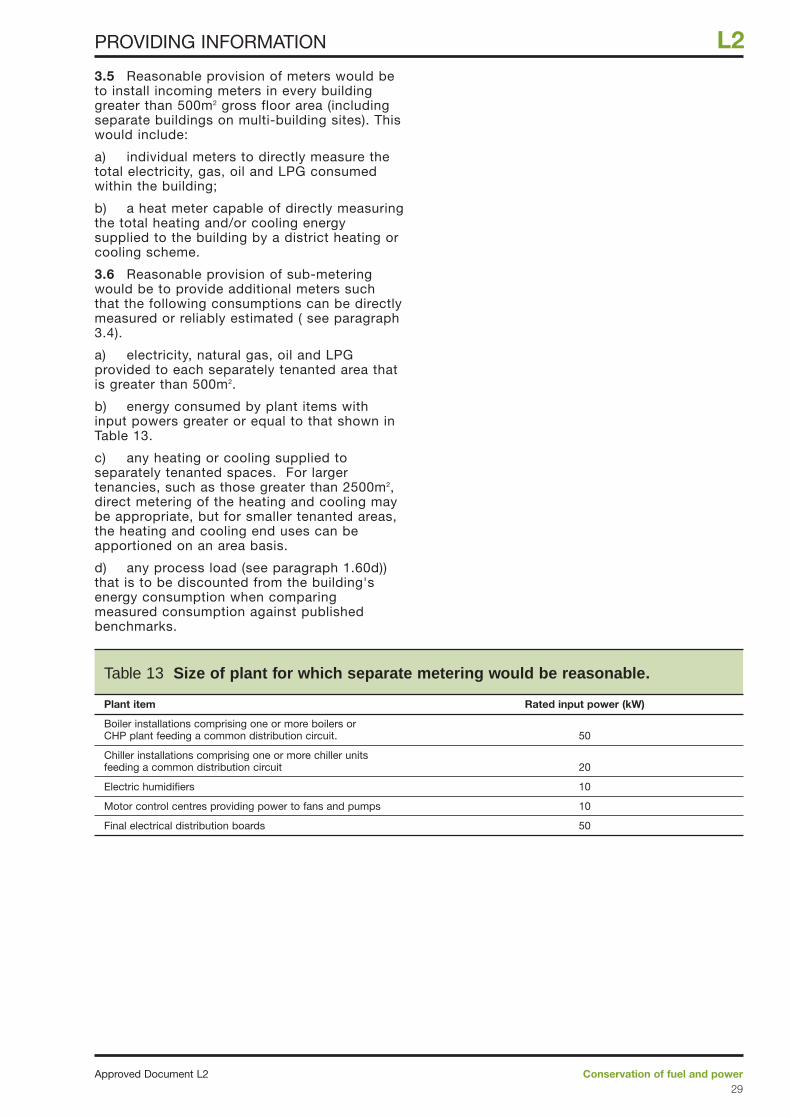
3.5 Reasonable provision of meters would beto install incoming meters in every buildinggreater than 500m2 gross floor area (includingseparate buildings on multi-building sites). Thiswould include:
a) individual meters to directly measure thetotal electricity, gas, oil and LPG consumedwithin the building;
b) a heat meter capable of directly measuringthe total heating and/or cooling energysupplied to the building by a district heating orcooling scheme.
3.6 Reasonable provision of sub-meteringwould be to provide additional meters suchthat the following consumptions can be directlymeasured or reliably estimated ( see paragraph3.4).
a) electricity, natural gas, oil and LPGprovided to each separately tenanted area thatis greater than 500m2.
b) energy consumed by plant items withinput powers greater or equal to that shown inTable 13.
c) any heating or cooling supplied toseparately tenanted spaces. For largertenancies, such as those greater than 2500m2,direct metering of the heating and cooling maybe appropriate, but for smaller tenanted areas,the heating and cooling end uses can beapportioned on an area basis.
d) any process load (see paragraph 1.60d))that is to be discounted from the building'senergy consumption when comparingmeasured consumption against publishedbenchmarks.
Conservation of fuel and powerApproved Document L229
L2PROVIDING INFORMATION
Table 13 Size of plant for which separate metering would be reasonable.
Plant item Rated input power (kW)
Boiler installations comprising one or more boilers or CHP plant feeding a common distribution circuit. 50
Chiller installations comprising one or more chiller units feeding a common distribution circuit 20
Electric humidifiers 10
Motor control centres providing power to fans and pumps 10
Final electrical distribution boards 50
Replacement of a controlledservice or fitting4.1 “Controlled service or fitting” is defined inRegulation 2(1) of the Building Regulations2000 (as amended by the Building(Amendment) Regulations 2001) as follows:
Controlled service or fitting means a service orfitting in relation to which part G, H, J or L ofSchedule 1 imposes a requirement.
4.2 Building work is defined in Regulation 3(1)to include the provision or extension of acontrolled service or fitting in or in connectionwith a building.
4.3 Reasonable provision where undertakingreplacement work on controlled services orfittings (whether replacing with new butidentical equipment or with different equipmentand whether the work is solely in connectionwith controlled services or includes work onthem) depends on the circumstances in theparticular case and would also need to takeaccount of historic value (see paragraph 4.10).Possible ways of meeting the requirementsinclude the following:
a) Windows, doors and rooflights. Whenthese elements are to be replaced, provideunits that meet the requirements for newbuildings or that provide a centre-paneU-value no worse than 1.2 W/m2K (therequirement does not apply to repair work onparts of these elements, such as replacingbroken glass or sealed double-glazing units orreplacing rotten framing members). Thereplacement work should comply with therequirements of Part L and (unless onlynon-glazed fittings are involved) Part N. Inaddition the building should not have a worselevel of compliance, after the work, with otherapplicable Parts of Schedule 1. These mayinclude Parts B, F and J.
b) Heating systems. Where heating systemsare to be substantially replaced, providing anew heating system and controls as if they arenew installations. In lesser work, makereasonable provision for insulation, zoning,timing, temperature and interlock controls.Without prejudice to the need for compliancewith all the requirements in Schedule 1, theneed to comply with the requirements ofParts F and J should particularly be takeninto account.
c) Hot water systems. When substantiallyreplacing hot water systems, pipes andvessels – providing controls and insulation asif they are new installations. In lesser work,make reasonable provision for insulation,timing and thermostatic controls.
d) When replacing a complete lightingsystem serving more than 100m2 of floor area,provide a new lighting system as if for a newbuilding. Where only the complete luminairesare being replaced, provide new luminairesthat meet the the standards given inparagraphs 1.43 or 1.48 (but the requirementdoes not apply where only components suchas lamps or louvres are being replaced). Whereonly the control system is to be replaced,provide new controls that meet the standardsin paragraphs 1.56 to 1.58 (but therequirement does not apply where onlycomponents such as switches and relays arebeing replaced).
e) Air conditioning or mechanicalventilation systems. When replacing airconditioning or mechanical ventilation systemsthat serve more than 200m2 of floor area inoffice buildings, improving the CarbonPerformance Rating in line with the guidance inparagraphs 1.62 to 1.66 of this ApprovedDocument. In buildings other than offices,provide mechanical ventilation systems thatmeet the SFP standards in paragraph 1.67.
4.4 When carrying out work as described inparagraph 4.3 sub-clauses (b) to (e):
a) the work should be inspected andcommissioned following the guidance inparagraph 2.6.
b) the building log-book should be preparedor updated as necessary to provide theappropriate details of the replacementcontrolled service or fitting (paragraphs 3.1and 3.2).
c) the relevant part of the metering strategyshould be prepared or revised as necessary,and additional metering provided whereneeded so as to enable the energyconsumption of the replacement controlledservice or fitting to be effectively monitored(paragraphs 3.3 to 3.6).
Material Alterations4.5 “Material alterations” are defined inRegulation 3(2) as follows.
“An alteration is material for the purposes ofthese Regulations if the work, or any part of it,would at any stage result -
(a) in a building or controlled service or fittingnot complying with a relevant requirementwhere previously it did; or
(b) in a building or controlled service orfitting which before the work commenced didnot comply with a relevant requirement,being more unsatisfactory in relation to sucha requirement.”
SECTION 4: Work on existing buildings
Approved Document L2Conservation of fuel and power30
L2 WORK ON EXISTING BUILDINGS
4.6 “Relevant requirement" is defined inRegulation 3(3) as follows.
“In paragraph (2) "relevant requirement" meansany of the following applicable requirements ofSchedule 1, namely –
Part A (structure)
paragraph B1 (means of warning andescape)
paragraph B3 (internal fire spread -structure)
paragraph B4 (external fire spread)
paragraph B5 (access and facilities for thefire service)
Part M (access and facilities for disabledpeople).”
4.7 Reasonable provision where undertakingmaterial alterations depends on thecircumstances in the particular case and wouldneed to take account of historic value (seeparagraph 4.10 et seq). Without prejudice tothe need for compliance with all therequirements in Schedule 1, the need tocomply with the requirements of Parts Fand J should particularly be taken intoaccount. Possible ways of satisfying therequirements include:
a) Roof insulation. When substantiallyreplacing any of the major elements of a roofstructure - providing insulation to achieve theU-value for new buildings.
b) Floor insulation. Where the structure of aground floor is to be substantially replaced – orre-boarded, providing insulation in heatedrooms to the standard for new buildings.
c) Wall insulation. When substantiallyreplacing complete exposed walls or theirexternal renderings or cladding or internalsurface finishes, or the internal surfaces ofseparating walls to unheated spaces, providinga reasonable thickness of insulation.
d) Sealing measures. When carrying out anyof the above work, including reasonable sealingmeasures to improve airtightness.
e) Controlled services and fittings. Whenreplacing controlled services and fittings,following the guidance in paragraph 4.3and 4.4.
Material changes of use4.8 “Material changes of use” are defined inRegulation 5 as follows.
… for the purposes of these Regulations, thereis a material change of use where there is achange in the purposes for which or thecircumstances in which a building is used, sothat after that change -
(a) the building is used as a dwelling, wherepreviously it was not;
(b) the building contains a flat, wherepreviously it did not;
(c) the building is used as an hotel or aboarding house, where previously it was not;
(d) the building is used as an institution,where previously it was not;
(e) the building is used as a public building,where previously it was not;
(f) the building is not a building described inClasses I to VI in Schedule 2, where previouslyit was; or
(g) the building, which contains at least onedwelling, contains a greater or lesser number ofdwellings than it did previously.
4.9 Reasonable provision where undertaking amaterial change of use depends on thecircumstances in the particular case andwould need to take account of historic value(see paragraph 4.10 et seq). Without prejudiceto the need for compliance with all therequirements in Schedule 1, the need tocomply with the requirements of Parts Fand J should particularly be taken intoaccount. Possible ways of satisfying therequirements include:
a) Accessible lofts. When upgradinginsulation in accessible lofts, providingadditional insulation to achieve a U-value notexceeding 0.25 W/m2K where the existinginsulation provides a U-value worse than0.35 W/m2K.
b) Roof insulation. When substantiallyreplacing any of the major elements of a roofstructure - providing insulation to achieve theU-value considered reasonable for newbuildings.
c) Floor insulation. Where the structure of aground floor is to be substantially replaced –providing insulation in heated rooms to thestandard considered reasonable for newbuildings.
d) Wall insulation. When substantiallyreplacing complete exposed walls or theirexternal renderings or cladding or internalsurface finishes, or the internal surfaces ofseparating walls to unheated spaces, providinga reasonable thickness of insulation.
e) Sealing measures. When carrying out anyof the above work, including reasonable sealingmeasures to improve airtightness.
f) Controlled services and fittings. Whenreplacing controlled services and fittings,following the guidance in paragraphs 4.3and 4.4.
Conservation of fuel and powerApproved Document L231
L2WORK ON EXISTING BUILDINGS
Historic buildings4.10 Historic buildings include -
a) listed buildings,
b) buildings situated in conservation areas,
c) buildings which are of architectural andhistorical interest and which are referred to asa material consideration in a local authority’sdevelopment plan,
d) buildings of architectural and historicinterest within national parks, areas ofoutstanding natural beauty, and worldheritage sites.
4.11 The need to conserve the specialcharacteristics of such historic buildings needsto be recognised: see BS 791355. In such workthe aim should be to improve energy efficiencywhere and to the extent that it is practicallypossible, always provided that the work doesnot prejudice the character of the historicbuilding, or increase the risk of long-termdeterioration to the building fabric or fittings.In arriving at an appropriate balance betweenhistoric building conservation and energyconservation, it would be appropriate to takeinto account the advice of the local planningauthority’s conservation officer.
4.12 Particular issues relating to work inhistoric buildings that warrant sympathetictreatment and where advice from others couldtherefore be beneficial include –
a) restoring the historic character of abuilding that had been subject to previousinappropriate alteration, e.g. replacementwindows, doors and rooflights.
b) rebuilding a former historic building (e.g.following a fire or filling in a gap site in aterrace).
c) making provisions enabling the fabric to“breathe” to control moisture and potential longterm decay problems: see SPAB InformationSheet No 456.
Approved Document L2Conservation of fuel and power32
L2 WORK ON EXISTING BUILDINGS
55 BS 7913 The principles of the conservation of historicbuildings, BSI, 1998 provides guidance on theprinciples that should be applied when proposing workon historic buildings.
56 The need for old buildings to breathe, SPABInformation sheet 4, 1986.
Contents
Tables PAGE
Windows, doors and rooflights
Table A1: Indicative U-values for 34windows and rooflights with wood or PVC-U frames, and doors
Table A2: Indicative U-values for 35windows with metal frames
Table A3: Adjustments to U-values in 35Table A2 for frames with thermal breaks
Corrections to U-values of roofs, walls and floors
Table A4: Corrections to U-values 36
Roofs
Table A5: Base thickness of insulation 37between ceiling joists or rafters
Table A6: Base thickness of insulation 37between and over joists or rafters
Table A7: Base thickness for 37continuous insulation
Table A8: Allowable reduction in base 38thickness for common roof components
Walls
Table A9: Base thickness of 40insulation layer
Table A10: Allowable reduction in 40base thickness for common components
Table A11: Allowable reductions in base 41 thickness for concrete components
Table A12: Allowable reductions in base 41thickness for insulated timber framed walls
Ground floors
Table A13: Insulation thickness for 43solid floors in contact with the ground
Table A14: Insulation thickness for 44suspended timber ground floors
Table A15: Insulation thickness for 44suspended concrete beam and block ground floors
Upper floors
Table A16: Upper floors of timber 45construction
Table A17: Upper floors of concrete 45construction
Table A18: Upper floors: allowable 45reductions in base thickness for commoncomponents
Building materials
Table A19: Thermal conductivity of somecommon building materials 46
Note: The values in these tables have beenderived using the combined method, takinginto account the effects of thermal bridgingwhere appropriate. Intermediate values can beobtained from the tables by linear interpolation.As an alternative to using these tables, theprocedures in Appendices B and C can beused to obtain a more accurate calculation ofthe thickness of insulation required.
Example calculations
Note: the examples are offered as indicatingways of meeting the requirements of Part L butdesigners also have to ensure that theirdesigns comply with all the other parts ofSchedule 1 to the Building Regulations.
PAGE
Roofs
Example 1: Pitched roof with insulation 38between ceiling joists or between rafters
Example 2: Pitched roof with insulation 39between and over ceiling joists
Example 3: Concrete deck roof 40
Walls
Example 4: Masonry cavity wall with 41internal insulation
Example 5: Masonry cavity wall (tied 42with vertical-twist stainless-steel ties) filledwith insulation with plasterboard on dabs
Example 6: Masonry wall (tied with 42vertical-twist stainless-steel ties) with partial cavity-fill
Example 7: Timber-framed wall 43
Ground floors
Example 8: Solid floor in contact with 45the ground
Example 9: Suspended timber floor 45
Appendix A: Tables of U-values
Conservation of fuel and powerApproved Document L233
L2TABLES OF U-VALUES
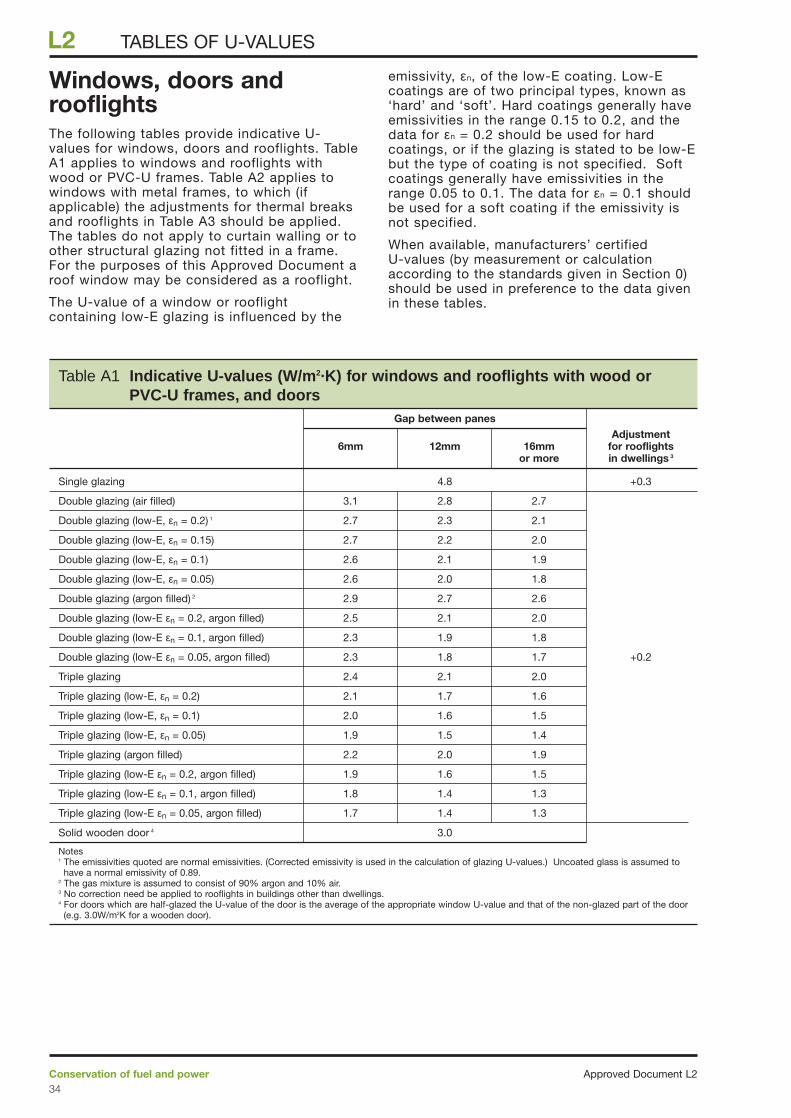
Windows, doors androoflightsThe following tables provide indicative U-values for windows, doors and rooflights. TableA1 applies to windows and rooflights withwood or PVC-U frames. Table A2 applies towindows with metal frames, to which (ifapplicable) the adjustments for thermal breaksand rooflights in Table A3 should be applied.The tables do not apply to curtain walling or toother structural glazing not fitted in a frame.For the purposes of this Approved Document aroof window may be considered as a rooflight.
The U-value of a window or rooflightcontaining low-E glazing is influenced by the
emissivity, εn, of the low-E coating. Low-Ecoatings are of two principal types, known as‘hard’ and ‘soft’. Hard coatings generally haveemissivities in the range 0.15 to 0.2, and thedata for εn = 0.2 should be used for hardcoatings, or if the glazing is stated to be low-Ebut the type of coating is not specified. Softcoatings generally have emissivities in therange 0.05 to 0.1. The data for εn = 0.1 shouldbe used for a soft coating if the emissivity isnot specified.
When available, manufacturers’ certified U-values (by measurement or calculationaccording to the standards given in Section 0)should be used in preference to the data givenin these tables.
Approved Document L2Conservation of fuel and power34
L2 TABLES OF U-VALUES
Table A1 Indicative U-values (W/m2·K) for windows and rooflights with wood or PVC-U frames, and doors
Gap between panesAdjustment
6mm 12mm 16mm for rooflights or more in dwellings 3
Single glazing 4.8 +0.3
Double glazing (air filled) 3.1 2.8 2.7
Double glazing (low-E, εn = 0.2) 1 2.7 2.3 2.1
Double glazing (low-E, εn = 0.15) 2.7 2.2 2.0
Double glazing (low-E, εn = 0.1) 2.6 2.1 1.9
Double glazing (low-E, εn = 0.05) 2.6 2.0 1.8
Double glazing (argon filled) 2 2.9 2.7 2.6
Double glazing (low-E εn = 0.2, argon filled) 2.5 2.1 2.0
Double glazing (low-E εn = 0.1, argon filled) 2.3 1.9 1.8
Double glazing (low-E εn = 0.05, argon filled) 2.3 1.8 1.7 +0.2
Triple glazing 2.4 2.1 2.0
Triple glazing (low-E, εn = 0.2) 2.1 1.7 1.6
Triple glazing (low-E, εn = 0.1) 2.0 1.6 1.5
Triple glazing (low-E, εn = 0.05) 1.9 1.5 1.4
Triple glazing (argon filled) 2.2 2.0 1.9
Triple glazing (low-E εn = 0.2, argon filled) 1.9 1.6 1.5
Triple glazing (low-E εn = 0.1, argon filled) 1.8 1.4 1.3
Triple glazing (low-E εn = 0.05, argon filled) 1.7 1.4 1.3
Solid wooden door 4 3.0
Notes1 The emissivities quoted are normal emissivities. (Corrected emissivity is used in the calculation of glazing U-values.) Uncoated glass is assumed to
have a normal emissivity of 0.89.2 The gas mixture is assumed to consist of 90% argon and 10% air. 3 No correction need be applied to rooflights in buildings other than dwellings. 4 For doors which are half-glazed the U-value of the door is the average of the appropriate window U-value and that of the non-glazed part of the door
(e.g. 3.0W/m2K for a wooden door).
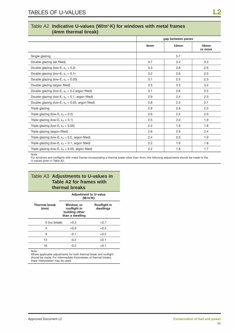
Conservation of fuel and powerApproved Document L235
L2TABLES OF U-VALUES
Table A2 Indicative U-values (W/m2·K) for windows with metal frames(4mm thermal break)
gap between panes
6mm 12mm 16mm or more
Single glazing 5.7
Double glazing (air filled) 3.7 3.4 3.3
Double glazing (low-E, εn = 0.2) 3.3 2.8 2.6
Double glazing (low-E, εn = 0.1) 3.2 2.6 2.5
Double glazing (low-E, εn = 0.05) 3.1 2.5 2.3
Double glazing (argon filled) 3.5 3.3 3.2
Double glazing (low-E, εn = 0.2,argon filled) 3.1 2.6 2.5
Double glazing (low-E, εn = 0.1, argon filled) 2.9 2.4 2.3
Double glazing (low-E, εn = 0.05, argon filled) 2.8 2.3 2.1
Triple glazing 2.9 2.6 2.5
Triple glazing (low-E, εn = 0.2) 2.6 2.2 2.0
Triple glazing (low-E, εn = 0.1) 2.5 2.0 1.9
Triple glazing (low-E, εn = 0.05) 2.4 1.9 1.8
Triple glazing (argon-filled) 2.8 2.5 2.4
Triple glazing (low-E, εn = 0.2, argon filled) 2.4 2.0 1.9
Triple glazing (low-E, εn = 0.1, argon filled) 2.2 1.9 1.8
Triple glazing (low-E, εn = 0.05, argon filled) 2.2 1.8 1.7
NoteFor windows and rooflights with metal frames incorporating a thermal break other than 4mm, the following adjustments should be made to theU-values given in Table A2.
Table A3 Adjustments to U-values inTable A2 for frames withthermal breaks
Adjustment to U-value (W/m2K)
Thermal break Window, or Rooflight in(mm) rooflight in dwellings
building other than a dwelling
0 (no break) +0.3 +0.7
4 +0.0 +0.3
8 -0.1 +0.2
12 -0.2 +0.1
16 -0.2 +0.1
NoteWhere applicable adjustments for both thermal break and rooflightshould be made. For intermediate thicknesses of thermal breaks,linear interpolation may be used.
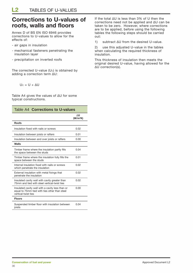
Corrections to U-values ofroofs, walls and floors Annex D of BS EN ISO 6946 providescorrections to U-values to allow for the effects of:
- air gaps in insulation
- mechanical fasteners penetrating theinsulation layer
- precipitation on inverted roofs
The corrected U-value (UC) is obtained byadding a correction term ∆U:
UC = U + ∆U
Table A4 gives the values of ∆U for sometypical constructions.
If the total ∆U is less than 3% of U then thecorrections need not be applied and ∆U can betaken to be zero. However, where correctionsare to be applied, before using the followingtables the following steps should be carriedout:
1) subtract ∆U from the desired U-value.
2) use this adjusted U-value in the tableswhen calculating the required thickness ofinsulation.
This thickness of insulation then meets theoriginal desired U-value, having allowed for the∆U correction(s).
Approved Document L2Conservation of fuel and power36
L2 TABLES OF U-VALUES
Table A4 Corrections to U-values∆U
(W/m2K)
Roofs
Insulation fixed with nails or screws 0.02
Insulation between joists or rafters 0.01
Insulation between and over joists or rafters 0.00
Walls
Timber frame where the insulation partly fills 0.04the space between the studs
Timber frame where the insulation fully fills the 0.01space between the studs
Internal insulation fixed with nails or screws 0.02 which penetrate the insulation
External insulation with metal fixings that 0.02penetrate the insulation
Insulated cavity wall with cavity greater than 0.0275mm and tied with steel vertical-twist ties
Insulated cavity wall with a cavity less than or 0.00equal to 75mm tied with ties other than steel vertical-twist ties
Floors
Suspended timber floor with insulation between 0.04joists
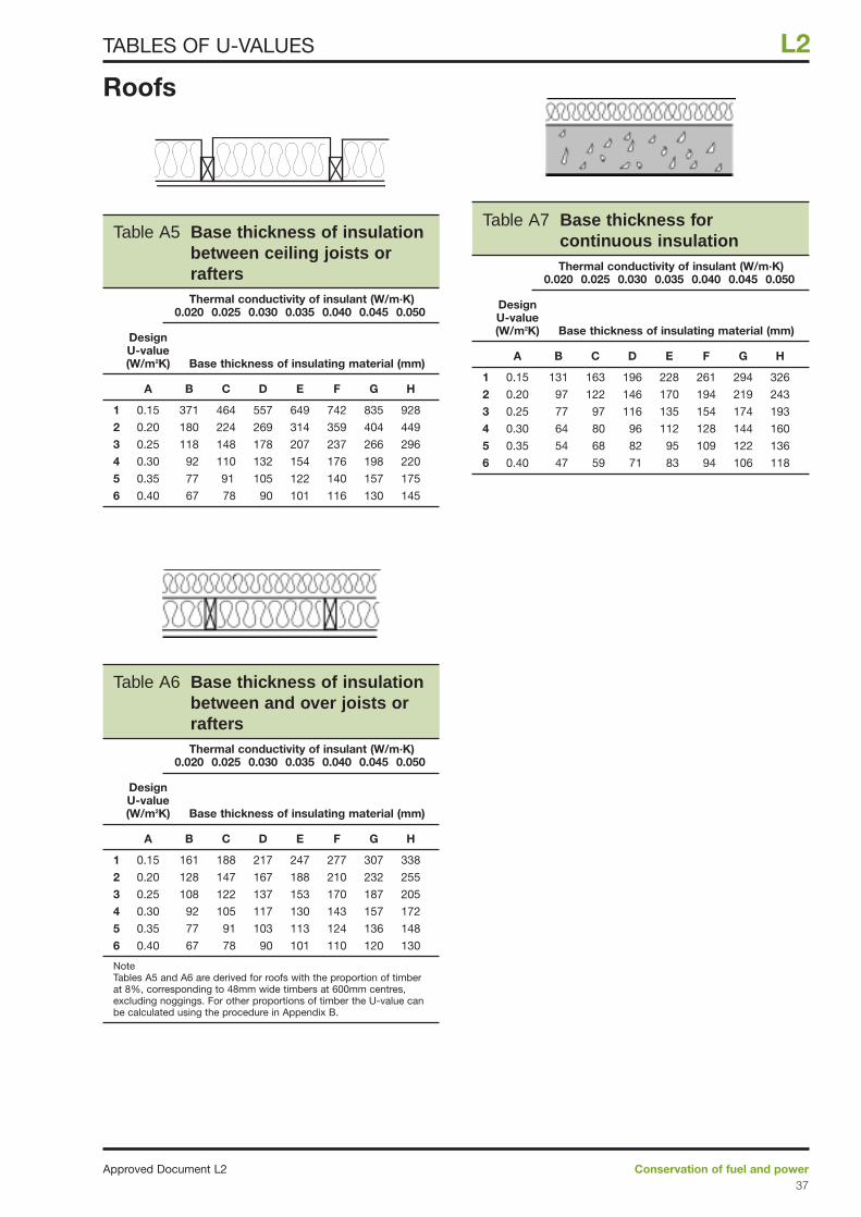
Roofs
Conservation of fuel and powerApproved Document L237
L2TABLES OF U-VALUES
Table A5 Base thickness of insulationbetween ceiling joists orraftersThermal conductivity of insulant (W/m·K)
0.020 0.025 0.030 0.035 0.040 0.045 0.050
DesignU-value(W/m2K) Base thickness of insulating material (mm)
A B C D E F G H
1 0.15 371 464 557 649 742 835 928
2 0.20 180 224 269 314 359 404 449
3 0.25 118 148 178 207 237 266 296
4 0.30 92 110 132 154 176 198 220
5 0.35 77 91 105 122 140 157 175
6 0.40 67 78 90 101 116 130 145
Table A6 Base thickness of insulationbetween and over joists orraftersThermal conductivity of insulant (W/m·K)
0.020 0.025 0.030 0.035 0.040 0.045 0.050
DesignU-value(W/m2K) Base thickness of insulating material (mm)
A B C D E F G H
1 0.15 161 188 217 247 277 307 338
2 0.20 128 147 167 188 210 232 255
3 0.25 108 122 137 153 170 187 205
4 0.30 92 105 117 130 143 157 172
5 0.35 77 91 103 113 124 136 148
6 0.40 67 78 90 101 110 120 130
NoteTables A5 and A6 are derived for roofs with the proportion of timberat 8%, corresponding to 48mm wide timbers at 600mm centres,excluding noggings. For other proportions of timber the U-value canbe calculated using the procedure in Appendix B.
Table A7 Base thickness forcontinuous insulationThermal conductivity of insulant (W/m·K)
0.020 0.025 0.030 0.035 0.040 0.045 0.050
DesignU-value(W/m2K) Base thickness of insulating material (mm)
A B C D E F G H
1 0.15 131 163 196 228 261 294 326
2 0.20 97 122 146 170 194 219 243
3 0.25 77 97 116 135 154 174 193
4 0.30 64 80 96 112 128 144 160
5 0.35 54 68 82 95 109 122 136
6 0.40 47 59 71 83 94 106 118
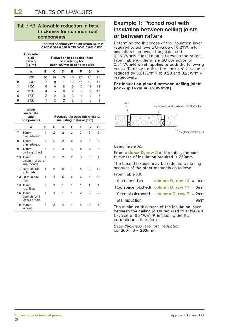
Example 1: Pitched roof withinsulation between ceiling joistsor between raftersDetermine the thickness of the insulation layerrequired to achieve a U-value of 0.21W/m2K ifinsulation is between the joists, and0.26 W/m2K if insulation is between the rafters.From Table A4 there is a ∆U correction of0.01 W/m2K which applies to both the followingcases. To allow for this, the ‘look-up’ U-value isreduced by 0.01W/m2K to 0.20 and 0.25W/m2Krespectively.
For insulation placed between ceiling joists(look-up U-value 0.20W/m2K)
Using Table A5:
From column D, row 2 of the table, the basethickness of insulation required is 269mm.
The base thickness may be reduced by takingaccount of the other materials as follows:
From Table A8:
19mm roof tiles column D, row 13 = 1mm
Roofspace (pitched) column D, row 11 = 6mm
10mm plasterboard column D, row 7 = 2mm
Total reduction = 9mm
The minimum thickness of the insulation layerbetween the ceiling joists required to achieve aU-value of 0.21W/m2K (including the ∆Ucorrection) is therefore:
Base thickness less total reductioni.e. 269 – 9 = 260mm.
Approved Document L2Conservation of fuel and power38
L2 TABLES OF U-VALUES
10 mm plasterboard
Insulation (thermal conductivity 0.030 W/m·K)Joist
Table A8 Allowable reduction in basethickness for common roofcomponents
Thermal conductivity of insulation (W/m·K) 0.020 0.025 0.030 0.035 0.040 0.045 0.050
Concreteslab Reduction in base thickness
density of insulating for (kg/m3) each 100mm of concrete slab
A B C D E F G H
1 600 10 13 15 18 20 23 25
2 800 7 9 11 13 14 16 18
3 1100 5 6 8 9 10 11 13
4 1300 4 5 6 7 8 9 10
5 1700 2 2 3 3 4 4 5
6 2100 1 2 2 2 3 3 3
Other materials
and Reduction in base thickness of components insulating material (mm)
A B C D E F G H
7 10mm 1 2 2 2 3 3 3plasterboard
8 13mm 2 2 2 3 3 4 4 plasterboard
9 13mm 2 2 3 3 4 4 5 sarking board
10 12mm 1 2 2 2 3 3 4calcium silicate liner board
11 Roof space 4 5 6 7 8 9 10 (pitched)
12 Roof space 3 4 5 6 6 7 8 (flat)
13 19mm 0 1 1 1 1 1 1 roof tiles
14 19mm 1 1 1 1 2 2 2 asphalt (or 3 layers of felt)
15 50mm 2 3 4 4 5 5 6 screed
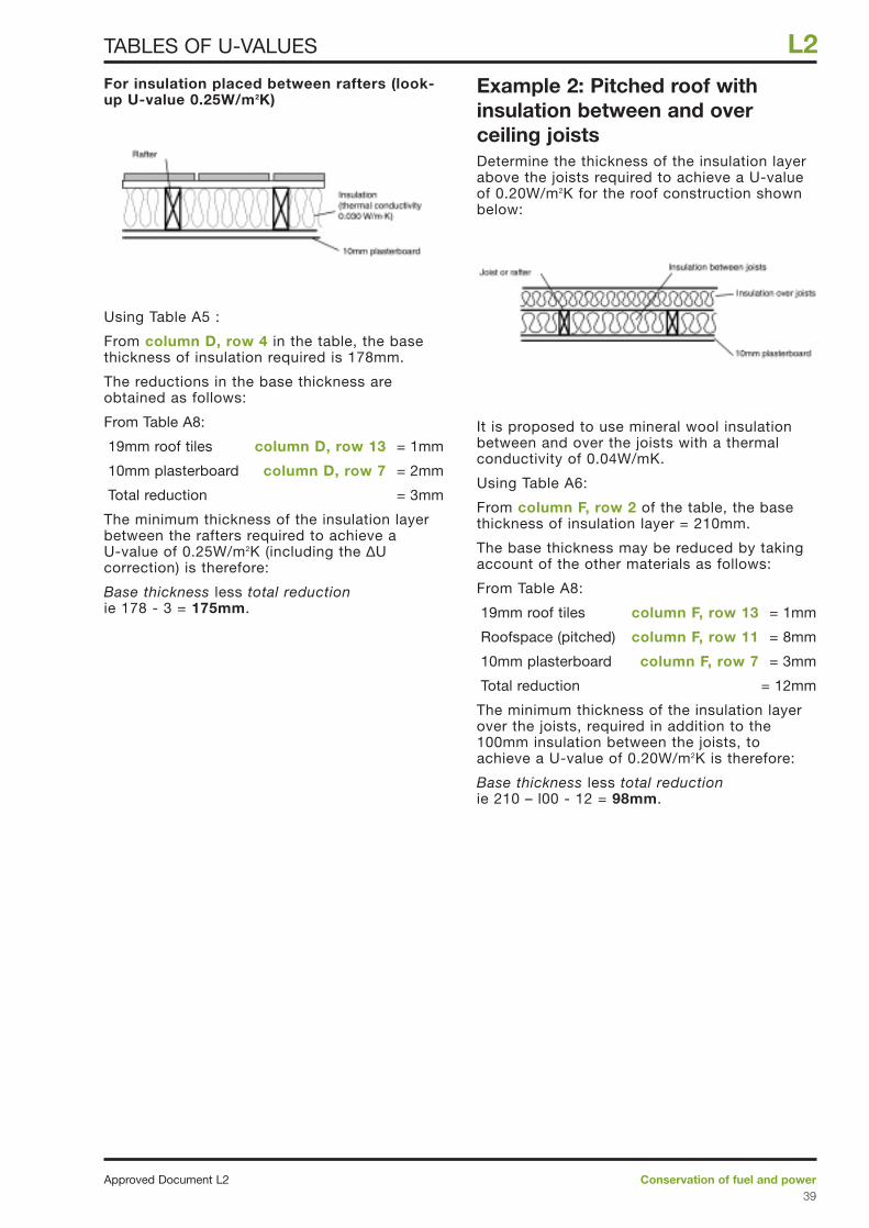
For insulation placed between rafters (look-up U-value 0.25W/m2K)
Using Table A5 :
From column D, row 4 in the table, the basethickness of insulation required is 178mm.
The reductions in the base thickness areobtained as follows:
From Table A8:
19mm roof tiles column D, row 13 = 1mm
10mm plasterboard column D, row 7 = 2mm
Total reduction = 3mm
The minimum thickness of the insulation layerbetween the rafters required to achieve a U-value of 0.25W/m2K (including the ∆Ucorrection) is therefore:
Base thickness less total reductionie 178 - 3 = 175mm.
Example 2: Pitched roof withinsulation between and overceiling joistsDetermine the thickness of the insulation layerabove the joists required to achieve a U-valueof 0.20W/m2K for the roof construction shownbelow:
It is proposed to use mineral wool insulationbetween and over the joists with a thermalconductivity of 0.04W/mK.
Using Table A6:
From column F, row 2 of the table, the basethickness of insulation layer = 210mm.
The base thickness may be reduced by takingaccount of the other materials as follows:
From Table A8:
19mm roof tiles column F, row 13 = 1mm
Roofspace (pitched) column F, row 11 = 8mm
10mm plasterboard column F, row 7 = 3mm
Total reduction = 12mm
The minimum thickness of the insulation layerover the joists, required in addition to the100mm insulation between the joists, toachieve a U-value of 0.20W/m2K is therefore:
Base thickness less total reductionie 210 – l00 - 12 = 98mm.
Conservation of fuel and powerApproved Document L239
L2TABLES OF U-VALUES
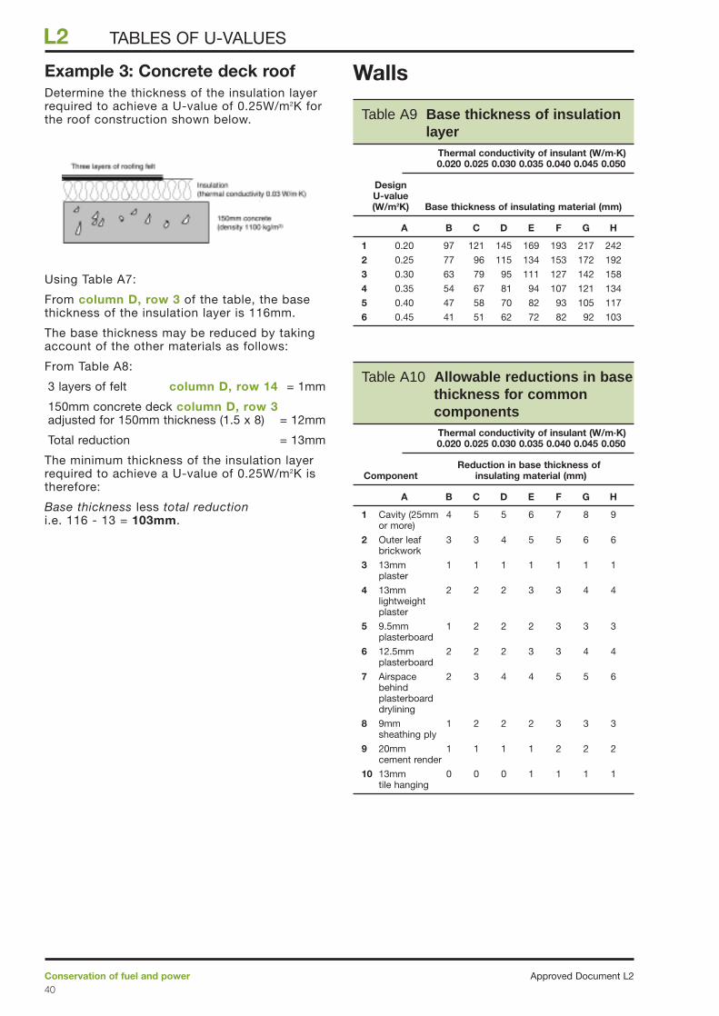
Example 3: Concrete deck roofDetermine the thickness of the insulation layerrequired to achieve a U-value of 0.25W/m2K forthe roof construction shown below.
Using Table A7:
From column D, row 3 of the table, the basethickness of the insulation layer is 116mm.
The base thickness may be reduced by takingaccount of the other materials as follows:
From Table A8:
3 layers of felt column D, row 14 = 1mm
150mm concrete deck column D, row 3adjusted for 150mm thickness (1.5 x 8) = 12mm
Total reduction = 13mm
The minimum thickness of the insulation layerrequired to achieve a U-value of 0.25W/m2K istherefore:
Base thickness less total reduction i.e. 116 - 13 = 103mm.
Walls
Approved Document L2Conservation of fuel and power40
L2 TABLES OF U-VALUES
Table A10 Allowable reductions in basethickness for commoncomponentsThermal conductivity of insulant (W/m·K) 0.020 0.025 0.030 0.035 0.040 0.045 0.050
Reduction in base thickness of Component insulating material (mm)
A B C D E F G H
1 Cavity (25mm 4 5 5 6 7 8 9 or more)
2 Outer leaf 3 3 4 5 5 6 6 brickwork
3 13mm 1 1 1 1 1 1 1 plaster
4 13mm 2 2 2 3 3 4 4 lightweight plaster
5 9.5mm 1 2 2 2 3 3 3 plasterboard
6 12.5mm 2 2 2 3 3 4 4 plasterboard
7 Airspace 2 3 4 4 5 5 6 behind plasterboard drylining
8 9mm 1 2 2 2 3 3 3 sheathing ply
9 20mm 1 1 1 1 2 2 2 cement render
10 13mm 0 0 0 1 1 1 1 tile hanging
Table A9 Base thickness of insulationlayer
Thermal conductivity of insulant (W/m·K) 0.020 0.025 0.030 0.035 0.040 0.045 0.050
DesignU-value(W/m2K) Base thickness of insulating material (mm)
A B C D E F G H
1 0.20 97 121 145 169 193 217 242
2 0.25 77 96 115 134 153 172 192
3 0.30 63 79 95 111 127 142 158
4 0.35 54 67 81 94 107 121 134
5 0.40 47 58 70 82 93 105 117
6 0.45 41 51 62 72 82 92 103
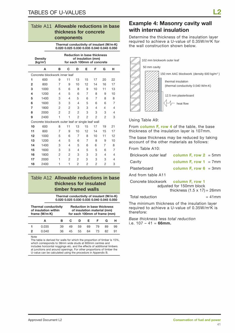
Example 4: Masonry cavity wallwith internal insulationDetermine the thickness of the insulation layerrequired to achieve a U-value of 0.35W/m2K forthe wall construction shown below.
Using Table A9:
From column F, row 4 of the table, the basethickness of the insulation layer is 107mm.
The base thickness may be reduced by takingaccount of the other materials as follows:
From Table A10:
Brickwork outer leaf column F, row 2 = 5mm
Cavity column F, row 1 = 7mm
Plasterboard column F, row 6 = 3mm
And from table A11
Concrete blockwork column F, row 1adjusted for 150mm block
thickness (1.5 x 17) = 26mm
Total reduction = 41mm
The minimum thickness of the insulation layerrequired to achieve a U-value of 0.35W/m2K istherefore:
Base thickness less total reduction i.e. 107 – 41 = 66mm.
102 mm brickwork outer leaf
50 mm cavity
150 mm AAC blockwork (density 600 kg/m3 )
thermal insulation
(thermal conductivity 0.040 W/m·K)
12.5 mm plasterboard
heat flow
Conservation of fuel and powerApproved Document L241
L2TABLES OF U-VALUES
Table A11 Allowable reductions in basethickness for concretecomponentsThermal conductivity of insulant (W/m·K) 0.020 0.025 0.030 0.035 0.040 0.045 0.050
Reduction in base thicknessDensity of insulation (mm)(kg/m3) for each 100mm of concrete
A B C D E F G H
Concrete blockwork inner leaf
1 600 9 11 13 15 17 20 22
2 800 7 9 10 12 14 16 17
3 1000 5 6 8 9 10 11 13
4 1200 4 5 6 7 8 9 10
5 1400 3 4 5 6 7 8 8
6 1600 3 3 4 5 6 6 7
7 1800 2 2 3 3 4 4 4
8 2000 2 2 2 3 3 3 4
9 2400 1 1 2 2 2 2 3
Concrete blockwork outer leaf or single leaf wall
10 600 8 11 13 15 17 19 21
11 800 7 9 10 12 14 15 17
12 1000 5 6 7 8 10 11 12
13 1200 4 5 6 7 8 9 10
14 1400 3 4 5 6 6 7 8
15 1600 3 3 4 5 5 6 7
16 1800 2 2 3 3 3 4 4
17 2000 1 2 2 3 3 3 4
18 2400 1 1 2 2 2 2 3
Table A12 Allowable reductions in basethickness for insulatedtimber framed wallsThermal conductivity of insulant (W/m·K) 0.020 0.025 0.030 0.035 0.040 0.045 0.050
Thermal conductivity Reduction in base thicknessof insulation within of insulation material (mm)frame (W/m·K) for each 100mm of frame (mm)
A B C D E F G H
1 0.035 39 49 59 69 79 89 99
2 0.040 36 45 55 64 73 82 91
NoteThe table is derived for walls for which the proportion of timber is 15%,which corresponds to 38mm wide studs at 600mm centres andincludes horizontal noggings etc. and the effects of additional timbersat junctions and around openings. For other proportions of timber theU-value can be calculated using the procedure in Appendix B.
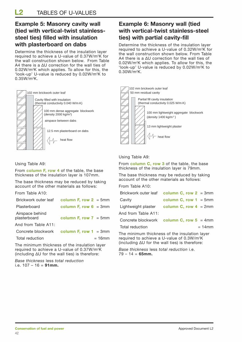
Example 5: Masonry cavity wall(tied with vertical-twist stainless-steel ties) filled with insulationwith plasterboard on dabsDetermine the thickness of the insulation layerrequired to achieve a U-value of 0.37W/m2K forthe wall construction shown below. From TableA4 there is a ∆U correction for the wall ties of0.02W/m2K which applies. To allow for this, the‘look-up’ U-value is reduced by 0.02W/m2K to0.35W/m2K.
Using Table A9:
From column F, row 4 of the table, the basethickness of the insulation layer is 107mm.
The base thickness may be reduced by takingaccount of the other materials as follows:
From Table A10:
Brickwork outer leaf column F, row 2 = 5mm
Plasterboard column F, row 6 = 3mm
Airspace behind plasterboard column F, row 7 = 5mm
And from Table A11:
Concrete blockwork column F, row 1 = 3mm
Total reduction = 16mm
The minimum thickness of the insulation layerrequired to achieve a U-value of 0.37W/m2K(including ∆U for the wall ties) is therefore:
Base thickness less total reduction i.e. 107 – 16 = 91mm.
Example 6: Masonry wall (tiedwith vertical-twist stainless-steelties) with partial cavity-fillDetermine the thickness of the insulation layerrequired to achieve a U-value of 0.32W/m2K forthe wall construction shown below. From TableA4 there is a ∆U correction for the wall ties of0.02W/m2K which applies. To allow for this, the‘look-up’ U-value is reduced by 0.02W/m2K to0.30W/m2K.
Using Table A9:
From column C, row 3 of the table, the basethickness of the insulation layer is 79mm.
The base thickness may be reduced by takingaccount of the other materials as follows:
From Table A10:
Brickwork outer leaf column C, row 2 = 3mm
Cavity column C, row 1 = 5mm
Lightweight plaster column C, row 4 = 2mm
And from Table A11:
Concrete blockwork column C, row 5 = 4mm
Total reduction = 14mm
The minimum thickness of the insulation layerrequired to achieve a U-value of 0.3W/m2K(including ∆U for the wall ties) is therefore:
Base thickness less total reduction i.e. 79 – 14 = 65mm.
102 mm brickwork outer leaf
Partial fill cavity insulation(thermal conductivity 0.025 W/m·K)
100 mm lightweight aggregate blockwork
(density 1400 kg/m 3 )
13 mm lightweight plaster
heat flow
50 mm residual cavity102 mm brickwork outer leaf
Cavity filled with insulation(thermal conductivity 0.040 W/m·K)
100 mm dense aggregate blockwork (density 2000 kg/m3)
12.5 mm plasterboard on dabs
heat flow
airspace between dabs
Approved Document L2Conservation of fuel and power42
L2 TABLES OF U-VALUES
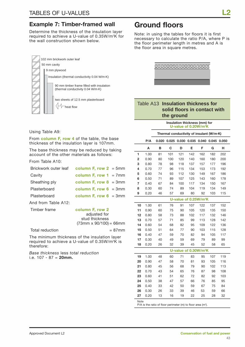
Example 7: Timber-framed wallDetermine the thickness of the insulation layerrequired to achieve a U-value of 0.35W/m2K forthe wall construction shown below.
Using Table A9:
From column F, row 4 of the table, the basethickness of the insulation layer is 107mm.
The base thickness may be reduced by takingaccount of the other materials as follows:
From Table A10:
Brickwork outer leaf column F, row 2 = 5mm
Cavity column F, row 1 = 7mm
Sheathing ply column F, row 8 = 3mm
Plasterboard column F, row 6 = 3mm
Plasterboard column F, row 6 = 3mm
And from Table A12:
Timber frame column F, row 2adjusted for
stud thickness (73mm x 90/100) = 66mm
Total reduction = 87mm
The minimum thickness of the insulation layerrequired to achieve a U-value of 0.35W/m2K istherefore:
Base thickness less total reductioni.e. 107 - 87 = 20mm.
Ground floorsNote: in using the tables for floors it is firstnecessary to calculate the ratio P/A, where P isthe floor perimeter length in metres and A isthe floor area in square metres.
102 mm brickwork outer leaf
Insulation (thermal conductivity 0.04 W/m·K)
90 mm timber frame filled with insulation(thermal conductivity 0.04 W/m·K)
two sheets of 12.5 mm plasterboard
heat flow
50 mm cavity
9 mm plywood
Conservation of fuel and powerApproved Document L243
L2TABLES OF U-VALUES
Table A13 Insulation thickness for solid floors in contact withthe ground
Insulation thickness (mm) forU-value of 0.20W/m2K
Thermal conductivity of insulant (W/m.K)
P/A 0.020 0.025 0.030 0.035 0.040 0.045 0.050
A B C D E F G H
1 1.00 81 101 121 142 162 182 202
2 0.90 80 100 120 140 160 180 200
3 0.80 78 98 118 137 157 177 196
4 0.70 77 96 115 134 153 173 192
5 0.60 74 93 112 130 149 167 186
6 0.50 71 89 107 125 143 160 178
7 0.40 67 84 100 117 134 150 167
8 0.30 60 74 89 104 119 134 149
9 0.20 46 57 69 80 92 103 115
U-value of 0.25W/m2K
10 1.00 61 76 91 107 122 137 152
11 0.90 60 75 90 105 120 135 150
12 0.80 58 73 88 102 117 132 146
13 0.70 57 71 85 99 113 128 142
14 0.60 54 68 82 95 109 122 136
15 0.50 51 64 77 90 103 115 128
16 0.40 47 59 70 82 94 105 117
17 0.30 40 49 59 69 79 89 99
18 0.20 26 32 39 45 52 58 65
U-value of 0.30W/m2K
19 1.00 48 60 71 83 95 107 119
20 0.90 47 58 70 81 93 105 116
21 0.80 45 56 68 79 90 102 113
22 0.70 43 54 65 76 87 98 108
23 0.60 41 51 62 72 82 92 103
24 0.50 38 47 57 66 76 85 95
25 0.40 33 42 50 59 67 75 84
26 0.30 26 33 39 46 53 59 66
27 0.20 13 16 19 22 25 28 32
NoteP/A is the ratio of floor perimeter (m) to floor area (m2).
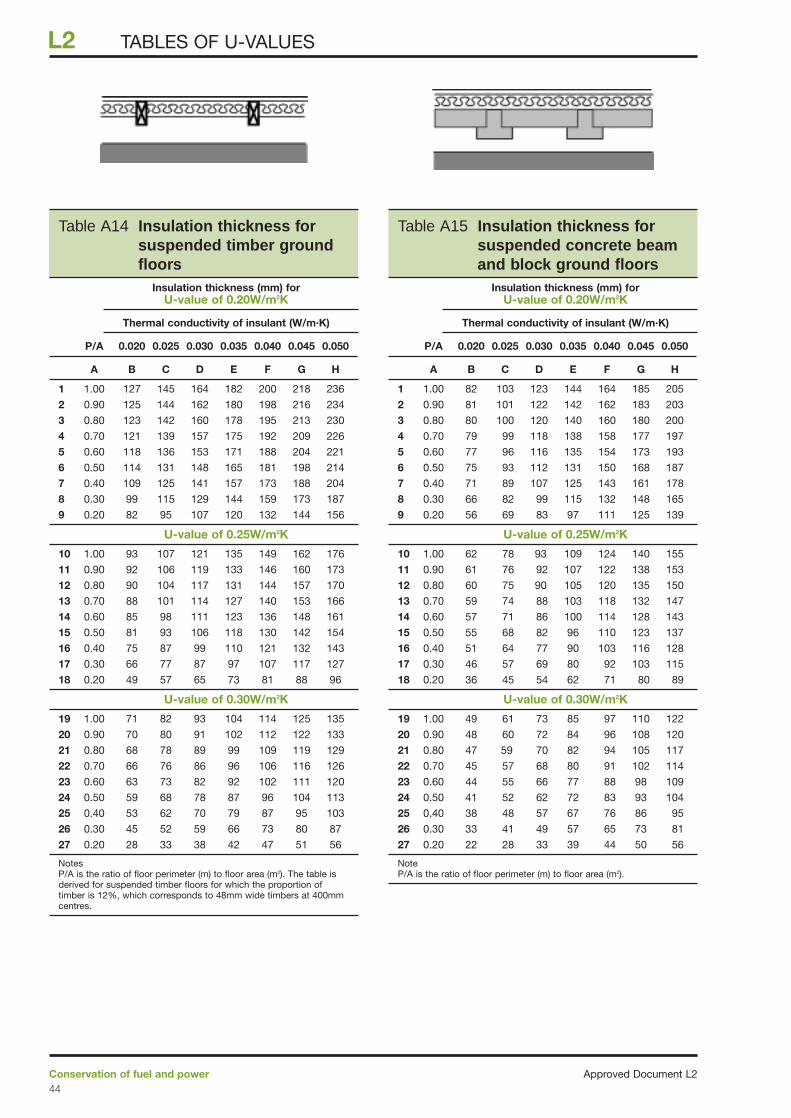
Approved Document L2Conservation of fuel and power44
L2 TABLES OF U-VALUES
Table A14 Insulation thickness forsuspended timber groundfloors
Table A15 Insulation thickness forsuspended concrete beamand block ground floors
Insulation thickness (mm) forU-value of 0.20W/m2K
Thermal conductivity of insulant (W/m.K)
P/A 0.020 0.025 0.030 0.035 0.040 0.045 0.050
A B C D E F G H
1 1.00 82 103 123 144 164 185 205
2 0.90 81 101 122 142 162 183 203
3 0.80 80 100 120 140 160 180 200
4 0.70 79 99 118 138 158 177 197
5 0.60 77 96 116 135 154 173 193
6 0.50 75 93 112 131 150 168 187
7 0.40 71 89 107 125 143 161 178
8 0.30 66 82 99 115 132 148 165
9 0.20 56 69 83 97 111 125 139
U-value of 0.25W/m2K
10 1.00 62 78 93 109 124 140 155
11 0.90 61 76 92 107 122 138 153
12 0.80 60 75 90 105 120 135 150
13 0.70 59 74 88 103 118 132 147
14 0.60 57 71 86 100 114 128 143
15 0.50 55 68 82 96 110 123 137
16 0.40 51 64 77 90 103 116 128
17 0.30 46 57 69 80 92 103 115
18 0.20 36 45 54 62 71 80 89
U-value of 0.30W/m2K
19 1.00 49 61 73 85 97 110 122
20 0.90 48 60 72 84 96 108 120
21 0.80 47 59 70 82 94 105 117
22 0.70 45 57 68 80 91 102 114
23 0.60 44 55 66 77 88 98 109
24 0.50 41 52 62 72 83 93 104
25 0.40 38 48 57 67 76 86 95
26 0.30 33 41 49 57 65 73 81
27 0.20 22 28 33 39 44 50 56
NoteP/A is the ratio of floor perimeter (m) to floor area (m2).
Insulation thickness (mm) forU-value of 0.20W/m2K
Thermal conductivity of insulant (W/m.K)
P/A 0.020 0.025 0.030 0.035 0.040 0.045 0.050
A B C D E F G H
1 1.00 127 145 164 182 200 218 236
2 0.90 125 144 162 180 198 216 234
3 0.80 123 142 160 178 195 213 230
4 0.70 121 139 157 175 192 209 226
5 0.60 118 136 153 171 188 204 221
6 0.50 114 131 148 165 181 198 214
7 0.40 109 125 141 157 173 188 204
8 0.30 99 115 129 144 159 173 187
9 0.20 82 95 107 120 132 144 156
U-value of 0.25W/m2K
10 1.00 93 107 121 135 149 162 176
11 0.90 92 106 119 133 146 160 173
12 0.80 90 104 117 131 144 157 170
13 0.70 88 101 114 127 140 153 166
14 0.60 85 98 111 123 136 148 161
15 0.50 81 93 106 118 130 142 154
16 0.40 75 87 99 110 121 132 143
17 0.30 66 77 87 97 107 117 127
18 0.20 49 57 65 73 81 88 96
U-value of 0.30W/m2K
19 1.00 71 82 93 104 114 125 135
20 0.90 70 80 91 102 112 122 133
21 0.80 68 78 89 99 109 119 129
22 0.70 66 76 86 96 106 116 126
23 0.60 63 73 82 92 102 111 120
24 0.50 59 68 78 87 96 104 113
25 0.40 53 62 70 79 87 95 103
26 0.30 45 52 59 66 73 80 87
27 0.20 28 33 38 42 47 51 56
NotesP/A is the ratio of floor perimeter (m) to floor area (m2). The table isderived for suspended timber floors for which the proportion oftimber is 12%, which corresponds to 48mm wide timbers at 400mmcentres.
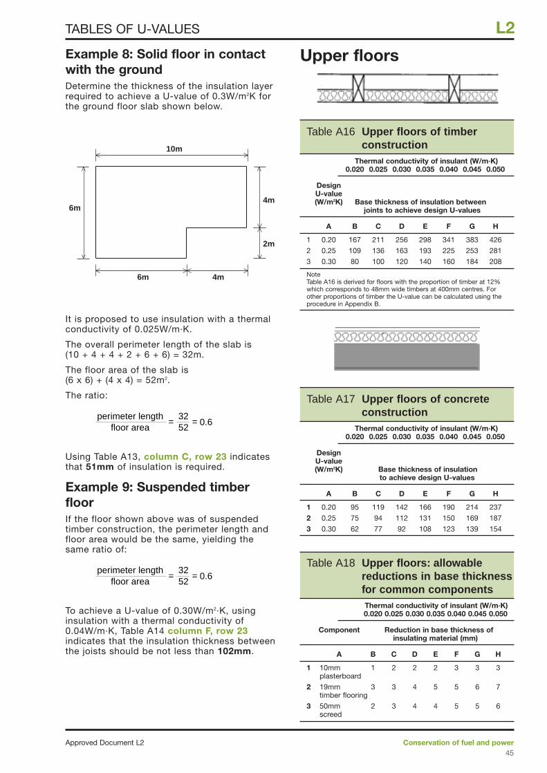
Example 8: Solid floor in contactwith the groundDetermine the thickness of the insulation layerrequired to achieve a U-value of 0.3W/m2K forthe ground floor slab shown below.
It is proposed to use insulation with a thermalconductivity of 0.025W/m·K.
The overall perimeter length of the slab is (10 + 4 + 4 + 2 + 6 + 6) = 32m.
The floor area of the slab is (6 x 6) + (4 x 4) = 52m2.
The ratio:
Using Table A13, column C, row 23 indicatesthat 51mm of insulation is required.
Example 9: Suspended timberfloorIf the floor shown above was of suspendedtimber construction, the perimeter length andfloor area would be the same, yielding thesame ratio of:
To achieve a U-value of 0.30W/m2·K, usinginsulation with a thermal conductivity of 0.04W/m·K, Table A14 column F, row 23indicates that the insulation thickness betweenthe joists should be not less than 102mm.
Upper floors
perimeter lengthfloor area
3252
= = 0.6
perimeter lengthfloor area
3252
= = 0.6
10m
6m 4m
2m
4m6m
Conservation of fuel and powerApproved Document L245
L2TABLES OF U-VALUES
Table A17 Upper floors of concreteconstruction
Thermal conductivity of insulant (W/m·K) 0.020 0.025 0.030 0.035 0.040 0.045 0.050
DesignU-value(W/m2K) Base thickness of insulation
to achieve design U-values
A B C D E F G H
1 0.20 95 119 142 166 190 214 237
2 0.25 75 94 112 131 150 169 187
3 0.30 62 77 92 108 123 139 154
Table A18 Upper floors: allowablereductions in base thicknessfor common componentsThermal conductivity of insulant (W/m·K) 0.020 0.025 0.030 0.035 0.040 0.045 0.050
Component Reduction in base thickness of insulating material (mm)
A B C D E F G H
1 10mm 1 2 2 2 3 3 3 plasterboard
2 19mm 3 3 4 5 5 6 7 timber flooring
3 50mm 2 3 4 4 5 5 6 screed
Table A16 Upper floors of timberconstruction
Thermal conductivity of insulant (W/m·K) 0.020 0.025 0.030 0.035 0.040 0.045 0.050
DesignU-value(W/m2K) Base thickness of insulation between
joints to achieve design U-values
A B C D E F G H
1 0.20 167 211 256 298 341 383 426
2 0.25 109 136 163 193 225 253 281
3 0.30 80 100 120 140 160 184 208
NoteTable A16 is derived for floors with the proportion of timber at 12%which corresponds to 48mm wide timbers at 400mm centres. Forother proportions of timber the U-value can be calculated using theprocedure in Appendix B.
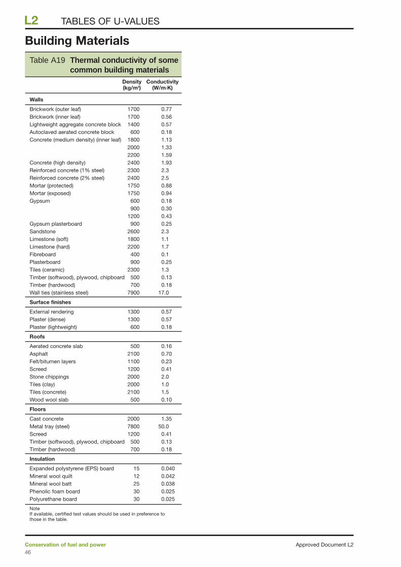
Building Materials
Approved Document L2Conservation of fuel and power46
L2 TABLES OF U-VALUES
Table A19 Thermal conductivity of somecommon building materials
Density Conductivity (kg/m2) (W/m·K)
Walls
Brickwork (outer leaf) 1700 0.77Brickwork (inner leaf) 1700 0.56Lightweight aggregate concrete block 1400 0.57Autoclaved aerated concrete block 600 0.18Concrete (medium density) (inner leaf) 1800 1.13
2000 1.332200 1.59
Concrete (high density) 2400 1.93Reinforced concrete (1% steel) 2300 2.3Reinforced concrete (2% steel) 2400 2.5Mortar (protected) 1750 0.88Mortar (exposed) 1750 0.94Gypsum 600 0.18
900 0.301200 0.43
Gypsum plasterboard 900 0.25Sandstone 2600 2.3Limestone (soft) 1800 1.1Limestone (hard) 2200 1.7Fibreboard 400 0.1Plasterboard 900 0.25Tiles (ceramic) 2300 1.3Timber (softwood), plywood, chipboard 500 0.13Timber (hardwood) 700 0.18Wall ties (stainless steel) 7900 17.0
Surface finishes
External rendering 1300 0.57 Plaster (dense) 1300 0.57Plaster (lightweight) 600 0.18
Roofs
Aerated concrete slab 500 0.16Asphalt 2100 0.70Felt/bitumen layers 1100 0.23Screed 1200 0.41 Stone chippings 2000 2.0 Tiles (clay) 2000 1.0Tiles (concrete) 2100 1.5Wood wool slab 500 0.10
Floors
Cast concrete 2000 1.35Metal tray (steel) 7800 50.0Screed 1200 0.41 Timber (softwood), plywood, chipboard 500 0.13Timber (hardwood) 700 0.18
Insulation
Expanded polystyrene (EPS) board 15 0.040Mineral wool quilt 12 0.042Mineral wool batt 25 0.038Phenolic foam board 30 0.025Polyurethane board 30 0.025
NoteIf available, certified test values should be used in preference tothose in the table.
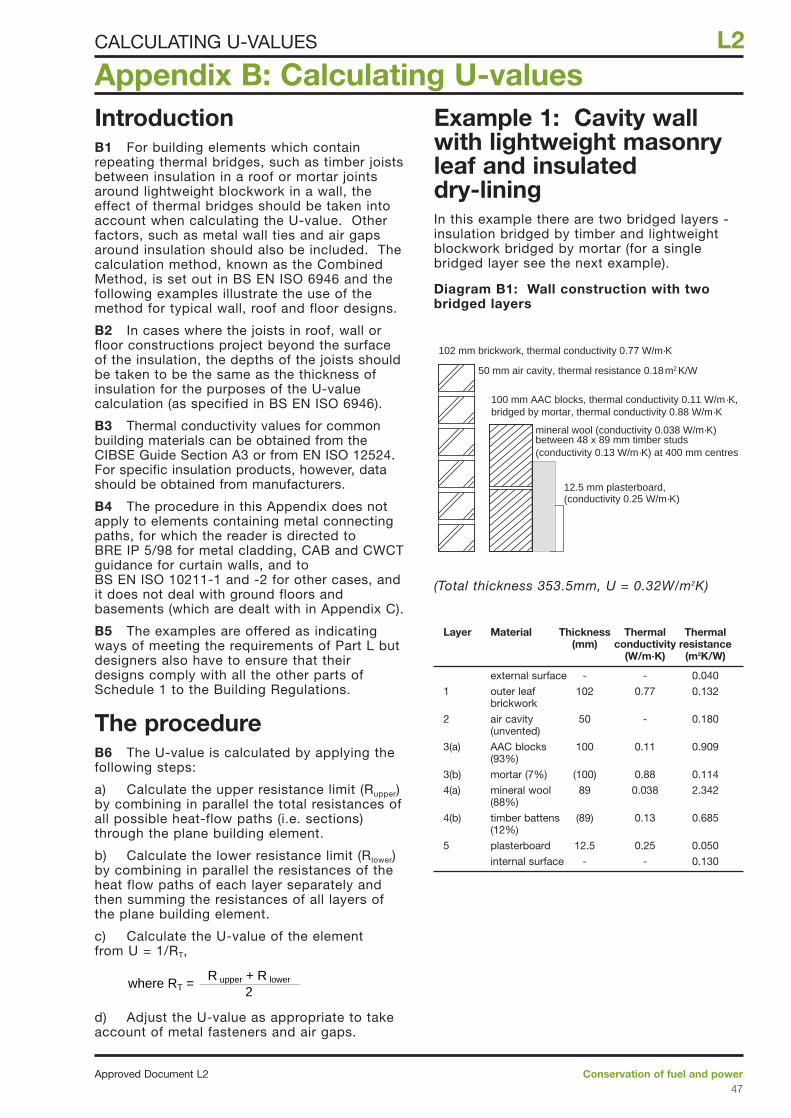
IntroductionB1 For building elements which containrepeating thermal bridges, such as timber joistsbetween insulation in a roof or mortar jointsaround lightweight blockwork in a wall, theeffect of thermal bridges should be taken intoaccount when calculating the U-value. Otherfactors, such as metal wall ties and air gapsaround insulation should also be included. Thecalculation method, known as the CombinedMethod, is set out in BS EN ISO 6946 and thefollowing examples illustrate the use of themethod for typical wall, roof and floor designs.
B2 In cases where the joists in roof, wall orfloor constructions project beyond the surfaceof the insulation, the depths of the joists shouldbe taken to be the same as the thickness ofinsulation for the purposes of the U-valuecalculation (as specified in BS EN ISO 6946).
B3 Thermal conductivity values for commonbuilding materials can be obtained from theCIBSE Guide Section A3 or from EN ISO 12524.For specific insulation products, however, datashould be obtained from manufacturers.
B4 The procedure in this Appendix does notapply to elements containing metal connectingpaths, for which the reader is directed toBRE IP 5/98 for metal cladding, CAB and CWCTguidance for curtain walls, and toBS EN ISO 10211-1 and -2 for other cases, andit does not deal with ground floors andbasements (which are dealt with in Appendix C).
B5 The examples are offered as indicatingways of meeting the requirements of Part L butdesigners also have to ensure that theirdesigns comply with all the other parts ofSchedule 1 to the Building Regulations.
The procedureB6 The U-value is calculated by applying thefollowing steps:
a) Calculate the upper resistance limit (Rupper)by combining in parallel the total resistances ofall possible heat-flow paths (i.e. sections)through the plane building element.
b) Calculate the lower resistance limit (Rlower)by combining in parallel the resistances of theheat flow paths of each layer separately andthen summing the resistances of all layers ofthe plane building element.
c) Calculate the U-value of the element from U = 1/RT,
d) Adjust the U-value as appropriate to takeaccount of metal fasteners and air gaps.
Example 1: Cavity wallwith lightweight masonryleaf and insulated dry-liningIn this example there are two bridged layers -insulation bridged by timber and lightweightblockwork bridged by mortar (for a singlebridged layer see the next example).
Diagram B1: Wall construction with twobridged layers
(Total thickness 353.5mm, U = 0.32W/m2K)
Layer Material Thickness Thermal Thermal (mm) conductivity resistance
(W/m·K) (m2K/W)
external surface - - 0.040
1 outer leaf 102 0.77 0.132brickwork
2 air cavity 50 - 0.180(unvented)
3(a) AAC blocks 100 0.11 0.909(93%)
3(b) mortar (7%) (100) 0.88 0.114
4(a) mineral wool 89 0.038 2.342(88%)
4(b) timber battens (89) 0.13 0.685(12%)
5 plasterboard 12.5 0.25 0.050
internal surface - - 0.130
102 mm brickwork, thermal conductivity 0.77 W/m·K
50 mm air cavity, thermal resistance 0.18 m2 K/W
100 mm AAC blocks, thermal conductivity 0.11 W/m·K,bridged by mortar, thermal conductivity 0.88 W/m·K
mineral wool (conductivity 0.038 W/m·K)between 48 x 89 mm timber studs(conductivity 0.13 W/m·K) at 400 mm centres
12.5 mm plasterboard,(conductivity 0.25 W/m·K)
R upper + R lower
2where RT =
Appendix B: Calculating U-values
Conservation of fuel and powerApproved Document L247
L2CALCULATING U-VALUES
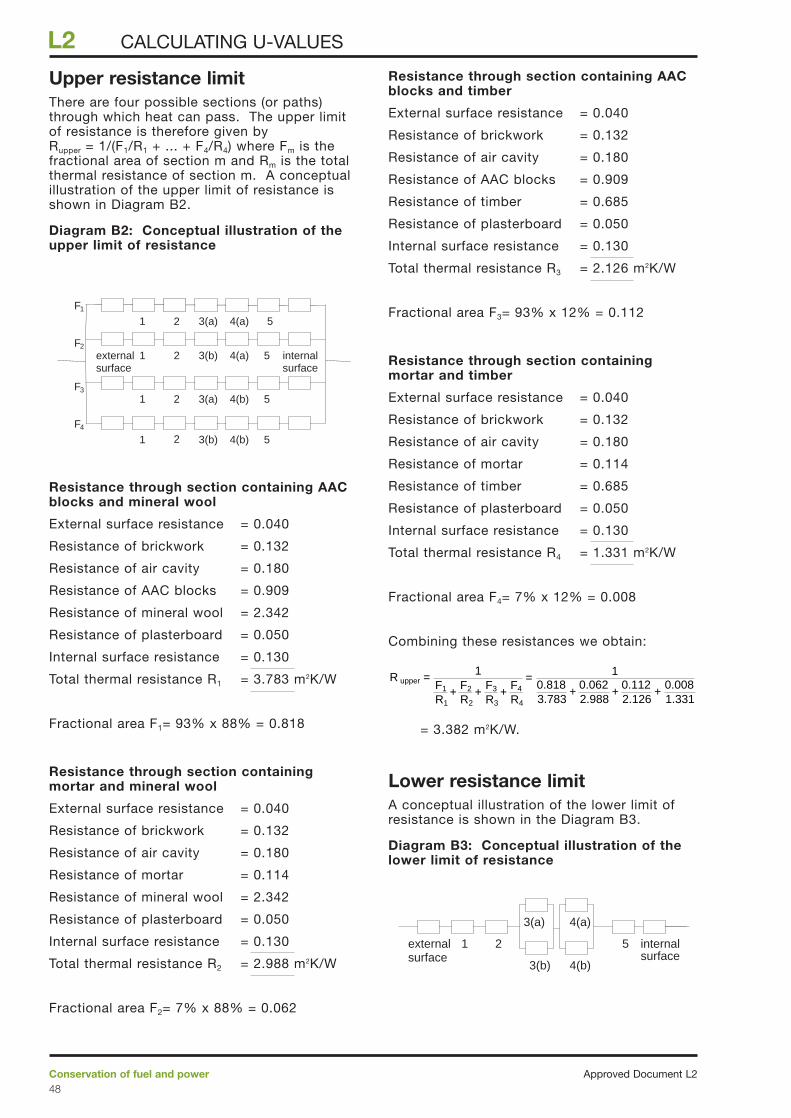
Upper resistance limitThere are four possible sections (or paths)through which heat can pass. The upper limitof resistance is therefore given by Rupper = 1/(F1/R1 + ... + F4/R4) where Fm is thefractional area of section m and Rm is the totalthermal resistance of section m. A conceptualillustration of the upper limit of resistance isshown in Diagram B2.
Diagram B2: Conceptual illustration of theupper limit of resistance
Resistance through section containing AACblocks and mineral wool
External surface resistance = 0.040
Resistance of brickwork = 0.132
Resistance of air cavity = 0.180
Resistance of AAC blocks = 0.909
Resistance of mineral wool = 2.342
Resistance of plasterboard = 0.050
Internal surface resistance = 0.130
Total thermal resistance R1 = 3.783 m2K/W
Fractional area F1= 93% x 88% = 0.818
Resistance through section containingmortar and mineral wool
External surface resistance = 0.040
Resistance of brickwork = 0.132
Resistance of air cavity = 0.180
Resistance of mortar = 0.114
Resistance of mineral wool = 2.342
Resistance of plasterboard = 0.050
Internal surface resistance = 0.130
Total thermal resistance R2 = 2.988 m2K/W
Fractional area F2= 7% x 88% = 0.062
Resistance through section containing AACblocks and timber
External surface resistance = 0.040
Resistance of brickwork = 0.132
Resistance of air cavity = 0.180
Resistance of AAC blocks = 0.909
Resistance of timber = 0.685
Resistance of plasterboard = 0.050
Internal surface resistance = 0.130
Total thermal resistance R3 = 2.126 m2K/W
Fractional area F3= 93% x 12% = 0.112
Resistance through section containingmortar and timber
External surface resistance = 0.040
Resistance of brickwork = 0.132
Resistance of air cavity = 0.180
Resistance of mortar = 0.114
Resistance of timber = 0.685
Resistance of plasterboard = 0.050
Internal surface resistance = 0.130
Total thermal resistance R4 = 1.331 m2K/W
Fractional area F4= 7% x 12% = 0.008
Combining these resistances we obtain:
= 3.382 m2K/W.
Lower resistance limitA conceptual illustration of the lower limit ofresistance is shown in the Diagram B3.
Diagram B3: Conceptual illustration of thelower limit of resistance
4(a)
21 5 internalsurface
3(a)
externalsurface
4(b)3(b)
R upper = F1
R1+
F2
R2+
F3
R3+
F4
R4
10.8183.783
+0.0622.988
+0.1122.126
+0.0081.331
1=
externalsurface
internalsurface
1 4(a)2
2
2
2
1
53(b)
F1
F2
3(a) 4(b) 5F3
F4
3(b)
3(a) 4(a)
4(b) 5
5
1
1
Approved Document L2Conservation of fuel and power48
L2 CALCULATING U-VALUES
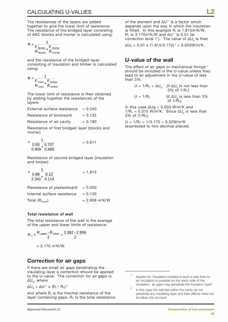
The resistances of the layers are addedtogether to give the lower limit of resistance.The resistance of the bridged layer consistingof AAC blocks and mortar is calculated using:
and the resistance of the bridged layerconsisting of insulation and timber is calculatedusing:
The lower limit of resistance is then obtainedby adding together the resistances of thelayers:
External surface resistance = 0.040
Resistance of brickwork = 0.132
Resistance of air cavity = 0.180
Resistance of first bridged layer (blocks andmortar)
= 0.611
Resistance of second bridged layer (insulationand timber)
= 1.815
Resistance of plasterboard = 0.050
Internal surface resistance = 0.130
Total (Rlower) = 2.958 m2K/W
Total resistance of wall
The total resistance of the wall is the averageof the upper and lower limits of resistance:
= 3.170 m2K/W.
Correction for air gapsIf there are small air gaps penetrating theinsulating layer a correction should be appliedto the U-value. The correction for air gaps is∆Ug, where
∆Ug = ∆U'' x (RI / RT) 2
and where RI is the thermal resistance of thelayer containing gaps, RT is the total resistance
of the element and ∆U'' is a factor whichdepends upon the way in which the insulationis fitted. In this example RI is 1.815m2K/W,RT is 3.170m2K/W and ∆U'' is 0.01 (iecorrection level 11). The value of ∆Ug is then
∆Ug = 0.01 x (1.815/3.170) 2 = 0.003W/m2K.
U-value of the wallThe effect of air gaps or mechanical fixings 2
should be included in the U-value unless theylead to an adjustment in the U-value of lessthan 3%.
U = 1/RT + ∆Ug (if ∆Ug is not less than3% of 1/RT)
U = 1/RT (if ∆Ug is less than 3% of 1/RT)
In this case ∆Ug = 0.003 W/m2K and1/RT = 0.315 W/m2K. Since ∆Ug is less than3% of (1/RT),
U = 1/RT = 1/3.170 = 0.32W/m2K(expressed to two decimal places).
R T =2
R upper + R lower
23.382 + 2.958
=
0.882.342
0.120.114
+
1=
0.930.909
0.7070.685
+
1=
R =F insul
R insul
F timber
R timber+
1
R =F blocks
R blocks
F mortar
R mortar+
1
Conservation of fuel and powerApproved Document L249
L2CALCULATING U-VALUES
1 Applies for “Insulation installed in such a way that noair circulation is possible on the warm side of theinsulation; air gaps may penetrate the insulation layer”
2 In this case the wall ties within the cavity do notpenetrate any insulating layer and their effects need notbe taken into account
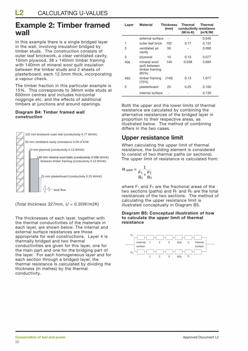
Example 2: Timber framedwallIn this example there is a single bridged layerin the wall, involving insulation bridged bytimber studs. The construction consists ofouter leaf brickwork, a clear ventilated cavity,10mm plywood, 38 x 140mm timber framingwith 140mm of mineral wool quilt insulationbetween the timber studs and 2 sheets ofplasterboard, each 12.5mm thick, incorporatinga vapour check.
The timber fraction in this particular example is15%. This corresponds to 38mm wide studs at600mm centres and includes horizontalnoggings etc. and the effects of additionaltimbers at junctions and around openings.
Diagram B4: Timber framed wallconstruction
(Total thickness 327mm, U = 0.30W/m2K)
The thicknesses of each layer, together withthe thermal conductivities of the materials ineach layer, are shown below. The internal andexternal surface resistances are thoseappropriate for wall constructions. Layer 4 isthermally bridged and two thermalconductivities are given for this layer, one forthe main part and one for the bridging part ofthe layer. For each homogeneous layer and foreach section through a bridged layer, thethermal resistance is calculated by dividing thethickness (in metres) by the thermalconductivity.
Layer Material Thickness Thermal Thermal (mm) conductivity resistance
(W/m·K) (m2K/W)
external surface - - 0.040
1 outer leaf brick 102 0.77 0.132
2 ventilated air 50 - 0.090cavity
3 plywood 10 0.13 0.077
4(a) mineral wool 140 0.038 3.684quilt between timber framing (85%)
4(b) timber framing (140) 0.13 1.077(15%)
5 plasterboard 25 0.25 0.100
internal surface - - 0.130
Both the upper and the lower limits of thermalresistance are calculated by combining thealternative resistances of the bridged layer inproportion to their respective areas, asillustrated below. The method of combiningdiffers in the two cases.
Upper resistance limitWhen calculating the upper limit of thermalresistance, the building element is consideredto consist of two thermal paths (or sections).The upper limit of resistance is calculated from:
where F1 and F2 are the fractional areas of thetwo sections (paths) and R1 and R2 are the totalresistances of the two sections. The method ofcalculating the upper resistance limit isillustrated conceptually in Diagram B5.
Diagram B5: Conceptual illustration of howto calculate the upper limit of thermalresistance
external
surface
internal
surface
1 4(a)2
21
3
F1
F2
3 4(b)
5
5
R upper =F1
R1+
F2
R2
1
102 mm brickwork outer leaf (conductivity 0.77 W/mK)
25 mm plasterboard (conductivity 0.25 W/mK)
heat flow
50 mm ventilated cavity (resistance 0.09 m K/W
10 mm plywood (conductivity 0.13 W/mK)
140 mm mineral wool batts (conductivity 0.038 W/mK)between timber framing (conductivity 0.13 W/mK)
2
Approved Document L2Conservation of fuel and power50
L2 CALCULATING U-VALUES
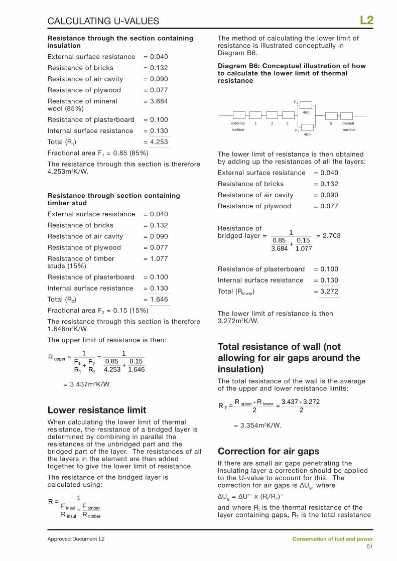
Resistance through the section containinginsulation
External surface resistance = 0.040
Resistance of bricks = 0.132
Resistance of air cavity = 0.090
Resistance of plywood = 0.077
Resistance of mineral = 3.684wool (85%)
Resistance of plasterboard = 0.100
Internal surface resistance = 0.130
Total (R1) = 4.253
Fractional area F1 = 0.85 (85%)
The resistance through this section is therefore4.253m2K/W.
Resistance through section containingtimber stud
External surface resistance = 0.040
Resistance of bricks = 0.132
Resistance of air cavity = 0.090
Resistance of plywood = 0.077
Resistance of timber = 1.077studs (15%)
Resistance of plasterboard = 0.100
Internal surface resistance = 0.130
Total (R2) = 1.646
Fractional area F2 = 0.15 (15%)
The resistance through this section is therefore1.646m2K/W
The upper limit of resistance is then:
= 3.437m2K/W.
Lower resistance limitWhen calculating the lower limit of thermalresistance, the resistance of a bridged layer isdetermined by combining in parallel theresistances of the unbridged part and thebridged part of the layer. The resistances of allthe layers in the element are then addedtogether to give the lower limit of resistance.
The resistance of the bridged layer iscalculated using:
The method of calculating the lower limit ofresistance is illustrated conceptually inDiagram B6.
Diagram B6: Conceptual illustration of howto calculate the lower limit of thermalresistance
The lower limit of resistance is then obtainedby adding up the resistances of all the layers:
External surface resistance = 0.040
Resistance of bricks = 0.132
Resistance of air cavity = 0.090
Resistance of plywood = 0.077
Resistance of bridged layer = = 2.703
Resistance of plasterboard = 0.100
Internal surface resistance = 0.130
Total (Rlower) = 3.272
The lower limit of resistance is then 3.272m2K/W.
Total resistance of wall (notallowing for air gaps around theinsulation)The total resistance of the wall is the averageof the upper and lower resistance limits:
= 3.354m2K/W.
Correction for air gaps If there are small air gaps penetrating theinsulating layer a correction should be appliedto the U-value to account for this. Thecorrection for air gaps is ∆Ug, where
∆Ug = ∆U'' x (RI/RT) 2
and where RI is the thermal resistance of thelayer containing gaps, RT is the total resistance
R T =2
R upper + R lower
23.437 + 3.272
=
0.853.684
+0.151.077
1
4(a)
21 5
F1
F2
internal
surface
3
4(b)
external
surface
R =F insul
R insul
F timber
R timber+
1
R upper = F1
R1+
F2
R2
10.854.253
+0.151.646
1=
Conservation of fuel and powerApproved Document L251
L2CALCULATING U-VALUES
of the element and ∆U'' is a factor whichdepends upon the way in which the insulationis fitted. In this example RI is 2.703m2K/W, RT
is 3.354m2K/W and ∆U'' is 0.01 (ie correctionlevel 1). The value of ∆Ug is then
∆Ug = 0.01 x (2.703/3.354)2 = 0.006W/m2K.
U-value of the wallThe effect of air gaps or mechanical fixingsshould be included in the U-value unless theylead to an adjustment in the U-value of lessthan 3%.
U = 1/RT + ∆Ug (if ∆Ug is not less than3% of 1/RT)
U = 1/RT (if ∆Ug is less than 3% of 1/RT)
In this case ∆Ug = 0.006W/m2K and 1/RT = 0.298W/m2K. Since ∆Ug is less than 3%of (1/RT),
U = 1/RT = 1 / 3.354 = 0.30W/m2K.
Approved Document L2Conservation of fuel and power52
L2 CALCULATING U-VALUES
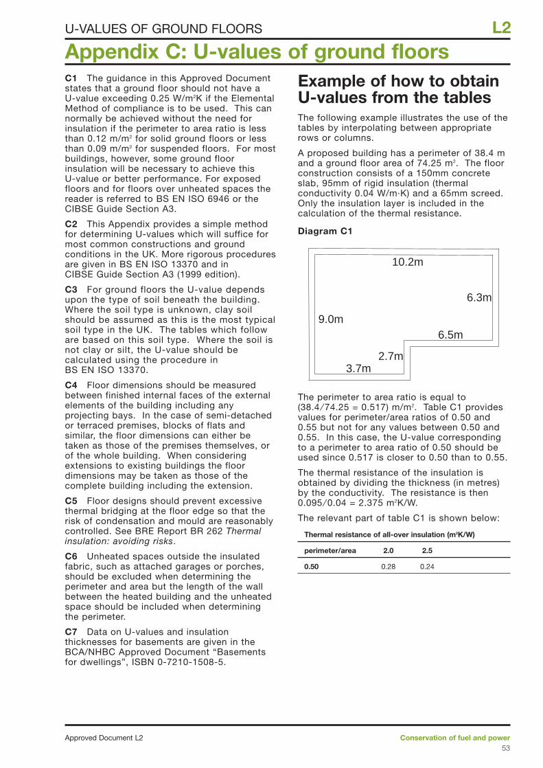
C1 The guidance in this Approved Documentstates that a ground floor should not have a U-value exceeding 0.25 W/m2K if the ElementalMethod of compliance is to be used. This cannormally be achieved without the need forinsulation if the perimeter to area ratio is lessthan 0.12 m/m2 for solid ground floors or lessthan 0.09 m/m2 for suspended floors. For mostbuildings, however, some ground floorinsulation will be necessary to achieve this U-value or better performance. For exposedfloors and for floors over unheated spaces thereader is referred to BS EN ISO 6946 or theCIBSE Guide Section A3.
C2 This Appendix provides a simple methodfor determining U-values which will suffice formost common constructions and groundconditions in the UK. More rigorous proceduresare given in BS EN ISO 13370 and inCIBSE Guide Section A3 (1999 edition).
C3 For ground floors the U-value dependsupon the type of soil beneath the building.Where the soil type is unknown, clay soilshould be assumed as this is the most typicalsoil type in the UK. The tables which followare based on this soil type. Where the soil isnot clay or silt, the U-value should becalculated using the procedure inBS EN ISO 13370.
C4 Floor dimensions should be measuredbetween finished internal faces of the externalelements of the building including anyprojecting bays. In the case of semi-detachedor terraced premises, blocks of flats andsimilar, the floor dimensions can either betaken as those of the premises themselves, orof the whole building. When consideringextensions to existing buildings the floordimensions may be taken as those of thecomplete building including the extension.
C5 Floor designs should prevent excessivethermal bridging at the floor edge so that therisk of condensation and mould are reasonablycontrolled. See BRE Report BR 262 Thermalinsulation: avoiding risks.
C6 Unheated spaces outside the insulatedfabric, such as attached garages or porches,should be excluded when determining theperimeter and area but the length of the wallbetween the heated building and the unheatedspace should be included when determiningthe perimeter.
C7 Data on U-values and insulationthicknesses for basements are given in theBCA/NHBC Approved Document “Basementsfor dwellings”, ISBN 0-7210-1508-5.
Example of how to obtainU-values from the tablesThe following example illustrates the use of thetables by interpolating between appropriaterows or columns.
A proposed building has a perimeter of 38.4 mand a ground floor area of 74.25 m2. The floorconstruction consists of a 150mm concreteslab, 95mm of rigid insulation (thermalconductivity 0.04 W/m·K) and a 65mm screed.Only the insulation layer is included in thecalculation of the thermal resistance.
Diagram C1
The perimeter to area ratio is equal to (38.4 ⁄ 74.25 = 0.517) m/m2. Table C1 providesvalues for perimeter/area ratios of 0.50 and0.55 but not for any values between 0.50 and0.55. In this case, the U-value correspondingto a perimeter to area ratio of 0.50 should beused since 0.517 is closer to 0.50 than to 0.55.
The thermal resistance of the insulation isobtained by dividing the thickness (in metres)by the conductivity. The resistance is then0.095 ⁄ 0.04 = 2.375 m2K/W.
The relevant part of table C1 is shown below:
Thermal resistance of all-over insulation (m2K/W)
perimeter/area 2.0 2.5
0.50 0.28 0.24
Appendix C: U-values of ground floors
Conservation of fuel and powerApproved Document L253
L2U-VALUES OF GROUND FLOORS
9.0m
6.3m
3.7m
6.5m
10.2m
2.7m
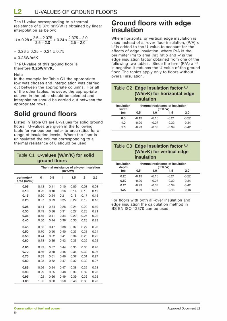
The U-value corresponding to a thermalresistance of 2.375 m2K/W is obtained by linearinterpolation as below:
= 0.28 x 0.25 + 0.24 x 0.75
= 0.25W/m2K
The U-value of this ground floor is therefore 0.25W/m2K.
NoteIn the example for Table C1 the appropriaterow was chosen and interpolation was carriedout between the appropriate columns. For allof the other tables, however, the appropriatecolumn in the table should be selected andinterpolation should be carried out between theappropriate rows.
Solid ground floorsListed in Table C1 are U-values for solid groundfloors. U-values are given in the followingtable for various perimeter-to-area ratios for arange of insulation levels. Where the floor isuninsulated the column corresponding to athermal resistance of 0 should be used.
Ground floors with edgeinsulationWhere horizontal or vertical edge insulation isused instead of all-over floor insulation, (P/A) xΨ is added to the U-value to account for theeffects of edge insulation, where P/A is theperimeter (m) to area (m2) ratio and Ψ is theedge insulation factor obtained from one of thefollowing two tables. Since the term (P/A) x Ψis negative it reduces the U-value of the groundfloor. The tables apply only to floors withoutoverall insulation.
For floors with both all-over insulation andedge insulation the calculation method inBS EN ISO 13370 can be used.
U = 0.28 x + 0.24 x2.5 – 2.3752.5 – 2.0
2.375 – 2.02.5 – 2.0
Approved Document L2Conservation of fuel and power54
L2 U-VALUES OF GROUND FLOORS
Table C1 U-values (W/m2K) for solidground floors
Thermal resistance of all-over insulation(m2K/W)
perimeter/ 0 0.5 1 1.5 2 2.5area (m/m2)
0.05 0.13 0.11 0.10 0.09 0.08 0.08
0.10 0.22 0.18 0.16 0.14 0.13 0.12
0.15 0.30 0.24 0.21 0.18 0.17 0.15
0.20 0.37 0.29 0.25 0.22 0.19 0.18
0.25 0.44 0.34 0.28 0.24 0.22 0.19
0.30 0.49 0.38 0.31 0.27 0.23 0.21
0.35 0.55 0.41 0.34 0.29 0.25 0.22
0.40 0.60 0.44 0.36 0.30 0.26 0.23
0.45 0.65 0.47 0.38 0.32 0.27 0.23
0.50 0.70 0.50 0.40 0.33 0.28 0.24
0.55 0.74 0.52 0.41 0.34 0.28 0.25
0.60 0.78 0.55 0.43 0.35 0.29 0.25
0.65 0.82 0.57 0.44 0.35 0.30 0.26
0.70 0.86 0.59 0.45 0.36 0.30 0.26
0.75 0.89 0.61 0.46 0.37 0.31 0.27
0.80 0.93 0.62 0.47 0.37 0.32 0.27
0.85 0.96 0.64 0.47 0.38 0.32 0.28
0.90 0.99 0.65 0.48 0.39 0.32 0.28
0.95 1.02 0.66 0.49 0.39 0.33 0.28
1.00 1.05 0.68 0.50 0.40 0.33 0.28
Table C2 Edge insulation factor Ψ(W/m·K) for horizontal edgeinsulation
insulation thermal resistance of insulation width (m2K/W)
(m) 0.5 1.0 1.5 2.0
0.5 -0.13 -0.18 -0.21 -0.22
1.0 -0.20 -0.27 -0.32 -0.34
1.5 -0.23 -0.33 -0.39 -0.42
Table C3 Edge insulation factor Ψ(W/m·K) for vertical edgeinsulation
insulation thermal resistance of insulation depth (m2K/W)
(m) 0.5 1.0 1.5 2.0
0.25 -0.13 -0.18 -0.21 -0.22
0.50 -0.20 -0.27 -0.32 -0.34
0.75 -0.23 -0.33 -0.39 -0.42
1.00 -0.26 -0.37 -0.43 -0.48
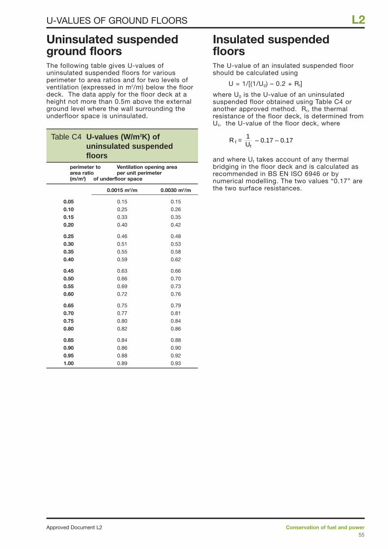
Uninsulated suspendedground floorsThe following table gives U-values ofuninsulated suspended floors for variousperimeter to area ratios and for two levels ofventilation (expressed in m2/m) below the floordeck. The data apply for the floor deck at aheight not more than 0.5m above the externalground level where the wall surrounding theunderfloor space is uninsulated.
Insulated suspendedfloorsThe U-value of an insulated suspended floorshould be calculated using
U = 1/[(1/U0) – 0.2 + Rf]
where U0 is the U-value of an uninsulatedsuspended floor obtained using Table C4 oranother approved method. Rf, the thermalresistance of the floor deck, is determined fromUf, the U-value of the floor deck, where
and where Uf takes account of any thermalbridging in the floor deck and is calculated asrecommended in BS EN ISO 6946 or bynumerical modelling. The two values “0.17” arethe two surface resistances.
R f = Uf
1– 0.17 – 0.17
Conservation of fuel and powerApproved Document L255
L2U-VALUES OF GROUND FLOORS
Table C4 U-values (W/m2K) ofuninsulated suspended floors
perimeter to Ventilation opening area area ratio per unit perimeter (m/m2) of underfloor space
0.0015 m2/m 0.0030 m2/m
0.05 0.15 0.15
0.10 0.25 0.26
0.15 0.33 0.35
0.20 0.40 0.42
0.25 0.46 0.48
0.30 0.51 0.53
0.35 0.55 0.58
0.40 0.59 0.62
0.45 0.63 0.66
0.50 0.66 0.70
0.55 0.69 0.73
0.60 0.72 0.76
0.65 0.75 0.79
0.70 0.77 0.81
0.75 0.80 0.84
0.80 0.82 0.86
0.85 0.84 0.88
0.90 0.86 0.90
0.95 0.88 0.92
1.00 0.89 0.93
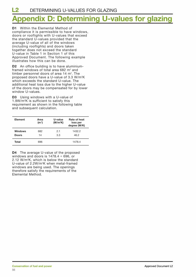
D1 Within the Elemental Method ofcompliance it is permissible to have windows,doors or rooflights with U-values that exceedthe standard U-values provided that theaverage U-value of all of the windows(including rooflights) and doors takentogether does not exceed the standardU-value in Table 1 in Section 1 of thisApproved Document. The following exampleillustrates how this can be done.
D2 An office building is to have aluminium-framed windows of total area 682 m2 andtimber personnel doors of area 14 m2. Theproposed doors have a U-value of 3.3 W/m2Kwhich exceeds the standard U-value. Theadditional heat loss due to the higher U-valueof the doors may be compensated for by lowerwindow U-values.
D3 Using windows with a U-value of1.9W/m2K is sufficient to satisfy thisrequirement as shown in the following tableand subsequent calculation.
Element Area U-value Rate of heat (m 2) (W/m2K) loss per
degree (W/K)
Windows 682 2.1 1432.2
Doors 14 3.3 46.2
Total 696 1478.4
D4 The average U-value of the proposedwindows and doors is 1478.4 ÷ 696, or2.12 W/m2K, which is below the standardU-value of 2.2W/m2K when metal-framedwindows are being used. The openingstherefore satisfy the requirements of theElemental Method.
Appendix D: Determining U-values for glazing
Approved Document L2Conservation of fuel and power56
L2 DETERMINING U-VALUES FOR GLAZING
Approved Document L2
L2
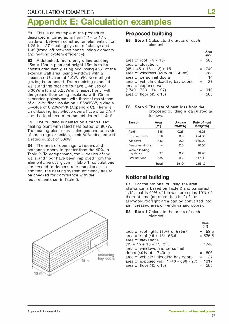
E1 This is an example of the proceduredescribed in paragraphs from 1.14 to 1.16(trade-off between construction elements), from1.25 to 1.27 (heating system efficiency) and1.32 (trade-off between construction elementsand heating system efficiency).
E2 A detached, four storey office building45m x 13m in plan and height 15m is to beconstructed with glazing occupying 45% of theexternal wall area, using windows with ameasured U-value of 2.0W/m2K. No rooflightglazing is proposed. The remaining exposedwalls and the roof are to have U-values of0.30W/m2K and 0.25W/m2K respectively, withthe ground floor being insulated with 75mmexpanded polystyrene with thermal resistanceof all-over floor insulation 1.85m2K/W, giving aU-value of 0.20W/m2K (Appendix C). There isan unloading bay whose doors have area 27m2
and the total area of personnel doors is 14m2.
E3 The building is heated by a centralisedheating plant with rated heat output of 90kW.The heating plant uses mains gas and consistsof three regular boilers, each 80% efficient witha rated output of 30kW.
E4 The area of openings (windows andpersonnel doors) is greater than the 40% inTable 2. To compensate, the U-values of thewalls and floor have been improved from theElemental values given in Table 1: calculationsare needed to demonstrate compliance. Inaddition, the heating system efficiency has tobe checked for compliance with therequirements set in Table 5.
Proposed buildingE5 Step 1 Calculate the areas of each
element:
Area(m2)
area of roof (45 x 13) = 585area of elevations (45 + 45 + 13 + 13) x 15 = 1740area of windows (45% of 1740m2) = 783area of personnel doors = 14area of vehicle unloading bay doors = 27area of exposed wall (1740 - 783 - 14 - 27) = 916area of floor (45 x 13) = 585
E6 Step 2 The rate of heat loss from theproposed building is calculated asfollows:
Element Area U-value Rate of heat (m2) (W/m2K) loss(W/K)
Roof 585 0.25 146.25
Exposed walls 916 0.3 274.80
Windows 783 2.0 1566.00
Personnel doors 14 2.0 28.00
Vehicle loading bay doors 27 0.7 18.90
Ground floor 585 0.2 117.00
Total 2910 2151.0
Notional buildingE7 For the notional building the areaallowance is based on Table 2 and paragraph1.15: that is 40% of the wall area plus 10% ofthe roof area (no more than half of theallowable rooflight area can be converted intoan increased area of windows and doors).
E8 Step 1 Calculate the areas of eachelement:
Area(m2)
area of roof lights (10% of 585m2) = 58.5area of roof (45 x 13) –58.5 = 526.5area of elevations (45 + 45 + 13 + 13) x15 = 1740area of windows and personnel doors (40% of 1740m2) = 696area of vehicle unloading bay doors = 27area of exposed wall (1740 - 696 - 27) = 1017area of floor (45 x 13) = 585
Appendix E: Calculation examples
Conservation of fuel and powerApproved Document L257
L2CALCULATION EXAMPLES
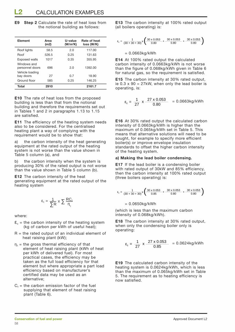
E9 Step 2 Calculate the rate of heat loss fromthe notional building as follows:
Element Area U-value Rate of heat(m2) (W/m2K) loss (W/K)
Roof lights 58.5 2.0 117.00
Roof 526.5 0.25 131.63
Exposed walls 1017 0.35 355.95
Windows and personnel doors 696 2.0 1392.00
Vehicle loading bay doors 27 0.7 18.90
Ground floor 585 0.25 146.25
Total 2910 2161.7
E10 The rate of heat loss from the proposedbuilding is less than that from the notionalbuilding and therefore the requirements set outin Tables 1 and 2 in paragraphs 1.13 to 1.15are satisfied.
E11 The efficiency of the heating system needsalso to be considered. For the centralisedheating plant a way of complying with therequirement would be to show that:
a) the carbon intensity of the heat generatingequipment at the rated output of the heatingsystem is not worse than the value shown inTable 5 column (a), and
b) the carbon intensity when the system isproducing 30% of the rated output is not worsethan the value shown in Table 5 column (b).
E12 The carbon intensity of the heatgenerating equipment at the rated output of theheating system
where:
εc = the carbon intensity of the heating system(kg of carbon per kWh of useful heat);
R = the rated output of an individual element ofheat raising plant (kW);
η t = the gross thermal efficiency of thatelement of heat raising plant (kWh of heatper kWh of delivered fuel). For mostpractical cases, the efficiency may betaken as the full load efficiency for thatelement but where appropriate a part loadefficiency based on manufacturer’scertified data may be used as analternative;
Cf = the carbon emission factor of the fuelsupplying that element of heat raisingplant (Table 6).
E13 The carbon intensity at 100% rated output(all boilers operating) is:
= 0.0663kg/kWh
E14 At 100% rated output the calculatedcarbon intensity of 0.0663kg/kWh is not worsethan the figure of 0.068kg/kWh given in Table 6for natural gas, so the requirement is satisfied.
E15 The carbon intensity at 30% rated output,ie 0.3 x 90 = 27kW, when only the lead boiler isoperating, is:
= 0.0663kg/kWh
E16 At 30% rated output the calculated carbonintensity of 0.0663kg/kWh is higher than themaximum of 0.065kg/kWh set in Table 5. Thismeans that alternative solutions will need to besought, for example to specify more efficientboiler(s) or improve envelope insulationstandards to offset the higher carbon intensityof the heating system.
a) Making the lead boiler condensing.
E17 If the lead boiler is a condensing boilerwith rated output of 30kW and 85% efficiency,then the carbon intensity at 100% rated output(three boilers operating) is:
= 0.0650kg/kWh
(which is less than the maximum carbonintensity of 0.068kg/kWh).
E18 The carbon intensity at 30% rated output,when only the condensing boiler only isoperating:
= 0.0624kg/kWh
E19 The calculated carbon intensity of theheating system is 0.0624kg/kWh, which is lessthan the maximum of 0.065kg/kWh set in Table5. The requirement as to heating efficiency isnow satisfied.
ε =0.85
27 x 0.053c
127
x
ε =(30 + 30 + 30)
10.85
30 x 0.053x
0.8030 x 0.053
+0.80
30 x 0.053+c ( )
ε =0.80
27 x 0.053c
127
x
ε =(30 + 30 + 30)
10.80
30 x 0.053x
0.8030 x 0.053
+0.80
30 x 0.053+c ( )
1R∑
=εc x RCf
ηt
∑
Approved Document L2Conservation of fuel and power58
L2 CALCULATION EXAMPLES
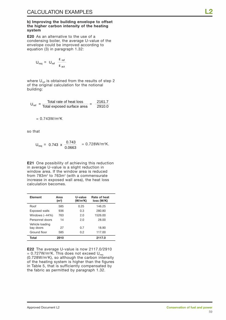
b) Improving the building envelope to offsetthe higher carbon intensity of the heatingsystem
E20 As an alternative to the use of acondensing boiler, the average U-value of theenvelope could be improved according toequation (3) in paragraph 1.32:
where Uref is obtained from the results of step 2of the original calculation for the notionalbuilding:
= 0.743W/m2K
so that
= 0.728W/m2K.
E21 One possibility of achieving this reductionin average U-value is a slight reduction inwindow area. If the window area is reducedfrom 783m2 to 763m2 (with a commensurateincrease in exposed wall area), the heat losscalculation becomes.
Element Area U-value Rate of heat(m2) (W/m2K) loss (W/K)
Roof 585 0.25 146.25
Exposed walls 936 0.3 280.80
Windows (~44%) 763 2.0 1526.00
Personnel doors 14 2.0 28.00
Vehicle loading bay doors 27 0.7 18.90
Ground floor 585 0.2 117.00
Total 2910 2117.0
E22 The average U-value is now 2117.0/2910= 0.727W/m2K. This does not exceed Ureq
(0.728W/m2K), so although the carbon intensityof the heating system is higher than the figuresin Table 5, that is sufficiently compensated bythe fabric as permitted by paragraph 1.32.
=Ureq 0.743 x0.743
0.0663
=Total exposed surface area
Total rate of heat loss2910.02161.7
=Uref
=Ureq Uref ε act
ε ref
Conservation of fuel and powerApproved Document L259
L2CALCULATION EXAMPLES
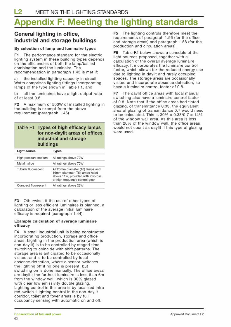
General lighting in office,industrial and storage buildingsBy selection of lamp and luminaire types
F1 The performance standard for the electriclighting system in these building types dependson the efficiencies of both the lamp/ballastcombination and the luminaire. Therecommendation in paragraph 1.43 is met if:
a) the installed lighting capacity in circuitWatts comprises lighting fittings incorporatinglamps of the type shown in Table F1, and
b) all the luminaires have a light output ratioof at least 0.6.
F2 A maximum of 500W of installed lighting inthe building is exempt from the aboverequirement (paragraph 1.46).
F3 Otherwise, if the use of other types oflighting or less efficient luminaires is planned, acalculation of the average initial luminaireefficacy is required (paragraph 1.44).
Example calculation of average luminaireefficacy
F4 A small industrial unit is being constructedincorporating production, storage and officeareas. Lighting in the production area (which isnon-daylit) is to be controlled by staged timeswitching to coincide with shift patterns. Thestorage area is anticipated to be occasionallyvisited, and is to be controlled by localabsence detection, where a sensor switchesthe lighting off if no one is present, butswitching on is done manually. The office areasare daylit; the furthest luminaire is less than 6mfrom the window wall, which is 30% glazedwith clear low emissivity double glazing.Lighting control in this area is by localised infrared switch. Lighting control in the non-daylitcorridor, toilet and foyer areas is by fulloccupancy sensing with automatic on and off.
F5 The lighting controls therefore meet therequirements of paragraph 1.56 (for the officeand storage areas) and paragraph 1.58 (for theproduction and circulation areas).
F6 Table F2 below shows a schedule of thelight sources proposed, together with acalculation of the overall average luminaireefficacy. It incorporates the luminaire controlfactor, which allows for the reduced energy usedue to lighting in daylit and rarely occupiedspaces. The storage areas are occasionallyvisited and incorporate absence detection, sohave a luminaire control factor of 0.8.
F7 The daylit office areas with local manualswitching also have a luminaire control factorof 0.8. Note that if the office areas had tintedglazing, of transmittance 0.33, the equivalentarea of glazing of transmittance 0.7 would needto be calculated. This is 30% x 0.33/0.7 = 14%of the window wall area. As this area is lessthan 20% of the window wall, the office areaswould not count as daylit if this type of glazingwere used.
Appendix F: Meeting the lighting standards
Approved Document L2Conservation of fuel and power60
L2 MEETING THE LIGHTING STANDARDS
Table F1 Types of high efficacy lampsfor non-daylit areas of offices,industrial and storagebuildings
Light source Types
High pressure sodium All ratings above 70W
Metal halide All ratings above 70W
Tubular fluorescent All 26mm diameter (T8) lamps and16mm diameter (T5) lamps ratedabove 11W, provided with low-lossor high frequency control gear.
Compact fluorescent All ratings above 26W

F8 From Table F2, the total corrected lumenoutput of all the lamps in the installation is333,730 lumens.
F9 The total circuit Watts of the installation is7292 Watts. Therefore the average luminaireefficacy is 333,730/7292 = 45.8 lumens/Watt.As this is greater than 40 lumens/Watt, theproposed lighting scheme therefore meets therequirements of this Approved Document. Notethat up to 500W of any form of lighting,including lamps in luminaires for which lightoutput ratios are unavailable, could also beinstalled in the building according toparagraph 1.46.
General lighting in otherbuilding typesLighting calculation procedure to showaverage circuit efficacy is not less than 50lumens/watt
F10 A lighting scheme is proposed for a newpublic house comprising a mixture ofconcealed perimeter lighting using highfrequency fluorescent fittings andsupplementary tungsten lamps in the diningarea. Lights in the dining and lounge areas areto be switched locally from behind the bar.Lighting to kitchens and toilets is to beswitched locally.
Conservation of fuel and powerApproved Document L261
L2MEETING THE LIGHTING STANDARDS
Position Number Description Circuit Lamp lumen Luminaire Luminaire Total corrected Total
N Watts (W) output Ø (lm) light output control luminaire output circuitper fitting per fitting ratio LOR factor CL =Nx Ø x Watts (W)
LOR/CL(lm)
Production 16 250W high bay 271 17000 0.8 1 217600 4336metal halide
Offices 12 4 x 18W 73 4600 0.57 0.8 39330 876fluorescent withaluminium Cat 2louvre and highfrequency controlgear
Storage 16 58W fluorescent 70 4600 0.6 0.8 55200 1120with aluminiumlouvres and mainsfrequency controlgear
Circulation, 30 24W compact 32 1800 0.4 1 21600 960toilets and fluorescent mainsfoyer frequency
downlights
Totals 333730 7292
Table F2
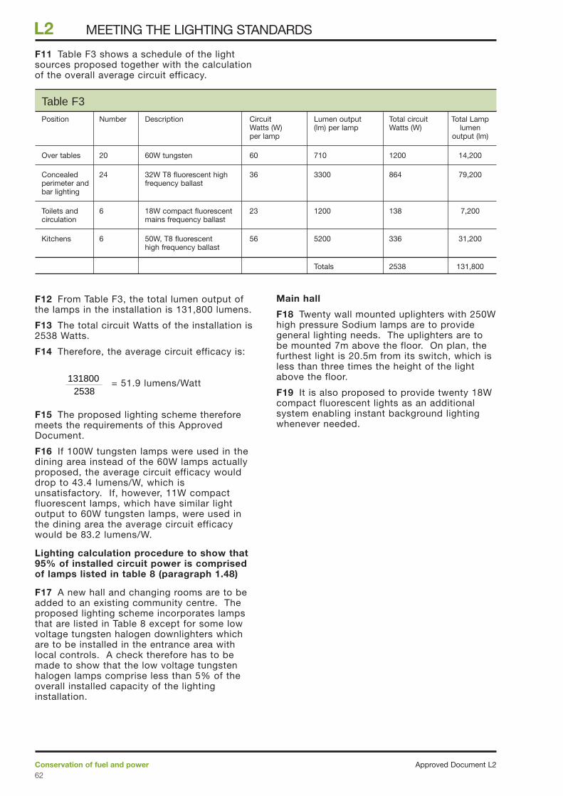
F11 Table F3 shows a schedule of the lightsources proposed together with the calculationof the overall average circuit efficacy.
F12 From Table F3, the total lumen output ofthe lamps in the installation is 131,800 lumens.
F13 The total circuit Watts of the installation is2538 Watts.
F14 Therefore, the average circuit efficacy is:
= 51.9 lumens/Watt
F15 The proposed lighting scheme thereforemeets the requirements of this ApprovedDocument.
F16 If 100W tungsten lamps were used in thedining area instead of the 60W lamps actuallyproposed, the average circuit efficacy woulddrop to 43.4 lumens/W, which isunsatisfactory. If, however, 11W compactfluorescent lamps, which have similar lightoutput to 60W tungsten lamps, were used inthe dining area the average circuit efficacywould be 83.2 lumens/W.
Lighting calculation procedure to show that95% of installed circuit power is comprisedof lamps listed in table 8 (paragraph 1.48)
F17 A new hall and changing rooms are to beadded to an existing community centre. Theproposed lighting scheme incorporates lampsthat are listed in Table 8 except for some lowvoltage tungsten halogen downlighters whichare to be installed in the entrance area withlocal controls. A check therefore has to bemade to show that the low voltage tungstenhalogen lamps comprise less than 5% of theoverall installed capacity of the lightinginstallation.
Main hall
F18 Twenty wall mounted uplighters with 250Whigh pressure Sodium lamps are to providegeneral lighting needs. The uplighters are tobe mounted 7m above the floor. On plan, thefurthest light is 20.5m from its switch, which isless than three times the height of the lightabove the floor.
F19 It is also proposed to provide twenty 18Wcompact fluorescent lights as an additionalsystem enabling instant background lightingwhenever needed.
2538131800
Approved Document L2Conservation of fuel and power62
L2 MEETING THE LIGHTING STANDARDS
Position Number Description Circuit Lumen output Total circuit Total LampWatts (W) (lm) per lamp Watts (W) lumenper lamp output (lm)
Over tables 20 60W tungsten 60 710 1200 14,200
Concealed 24 32W T8 fluorescent high 36 3300 864 79,200perimeter and frequency ballastbar lighting
Toilets and 6 18W compact fluorescent 23 1200 138 7,200circulation mains frequency ballast
Kitchens 6 50W, T8 fluorescent 56 5200 336 31,200high frequency ballast
Totals 2538 131,800
Table F3
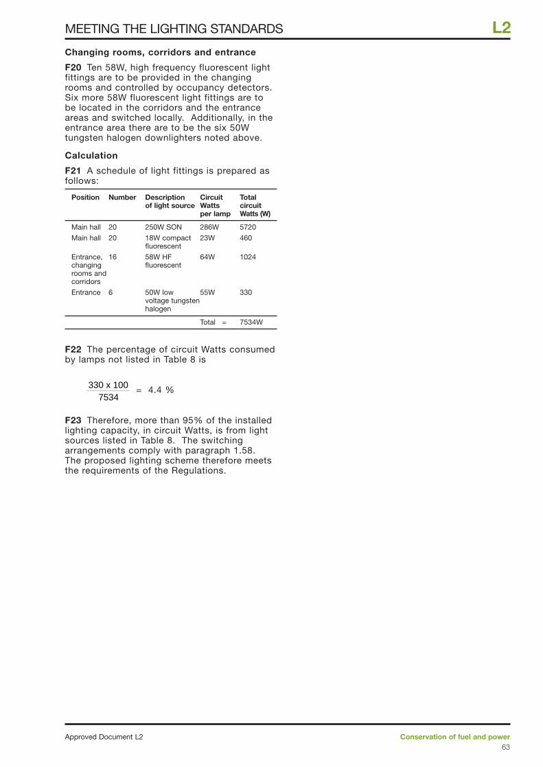
Changing rooms, corridors and entrance
F20 Ten 58W, high frequency fluorescent lightfittings are to be provided in the changingrooms and controlled by occupancy detectors.Six more 58W fluorescent light fittings are tobe located in the corridors and the entranceareas and switched locally. Additionally, in theentrance area there are to be the six 50Wtungsten halogen downlighters noted above.
Calculation
F21 A schedule of light fittings is prepared asfollows:
Position Number Description Circuit Totalof light source Watts circuit
per lamp Watts (W)
Main hall 20 250W SON 286W 5720
Main hall 20 18W compact 23W 460fluorescent
Entrance, 16 58W HF 64W 1024changing fluorescentrooms and corridors
Entrance 6 50W low 55W 330voltage tungsten halogen
Total = 7534W
F22 The percentage of circuit Watts consumedby lamps not listed in Table 8 is
= 4.4 %
F23 Therefore, more than 95% of the installedlighting capacity, in circuit Watts, is from lightsources listed in Table 8. The switchingarrangements comply with paragraph 1.58.The proposed lighting scheme therefore meetsthe requirements of the Regulations.
7534330 x 100
Conservation of fuel and powerApproved Document L263
L2MEETING THE LIGHTING STANDARDS
Assessing the contribution tocarbon emissions due to buildingservices design and operationG1 The efficiencies of buildings, and of theservices systems that produce the indoorconditions required by occupants, can beassessed and compared provided a consistentsystem is used to describe the buildings andtheir energy use.
G2 Applying such a consistent approach inthe office building sector has allowed energyconsumption benchmarks to be developed withwhich the performance of existing buildings, orthe likely performance of new designs, can becompared. The benchmarks result from anumber of surveys of operational buildings, andare included in Energy Consumption Guide 19“Energy use in offices” (ECON 19).
Performance benchmarks
G3 The information contained in ECON 19provides benchmarks for the energy consumedby ACMV, heating and lighting services,together with benchmark informationdescribing the hours of use of the equipment.Benchmarks also describe the energyconsumed by the additional equipmentnecessary to support use of the building fortypical office activities. The benchmarks referto office buildings described as representing‘typical’ and ‘good practice’ for the sector.
Design Assessment
G4 The annual energy likely to be consumedby a particular service can be estimated as theproduct of the total installed input powerrating of the plant installed to provide theservice and the annual hours of use of thatplant at the equivalent of full load. The annualhours of use can be considered to be theresult of combining a benchmark value for the‘typical’ hours of use of the service with amanagement factor that acts to reduce orincrease this value. The management factor isa number related to the provisions that havebeen included that have the potential to helpthe occupier control and manage the use ofthe plant.
G5 The Carbon Performance Rating (CPR)referred to in paragraphs G10 to G19 of thisAppendix is a technique for assessing thelikely performance of building servicessystems using this design information. It usesbenchmarks consistent with ECON19 and isintended to estimate the potential for efficientoperation of building services systems usinginformation available at the design orconstruction stage.
Performance assessment
G6 The inclusion of meters (Section 3 of thisApproved Document) improves the confidencewith which occupiers may assess their buildings’performance by estimating the energy consumedby servicing plant and the additional equipmentrequired for the full operation of the building.
G7 A technique of estimating operationalenergy consumption, and comparing theachieved performance of buildings with theECON19 benchmarks, has been developed toassess the achieved performance of officebuildings. This method is described in CIBSETechnical Memorandum TM 22 “EnergyAssessment and Reporting Methodology: OfficeAssessment Method”.
G8 A means of comparing the design ofservices with benchmarks of installed load andenergy use is described the CIBSE Guidevolume “Energy Efficiency in Buildings”.
G9 The results of ongoing performanceassessment could be used to provide valuableinformation from which to maintain and improveperformance benchmarks, and hence the CPRmethod, and to inform the design process.
The Carbon Performance Rating(CPR) The CPR for mechanical ventilation - CPR(MV)
G10 The assessment is based on thecalculation of a Carbon Performance Ratingusing the following relationship:
CPR(MV) = PD x HD x CD x FD
G11 The design is considered to representacceptable practice where the result of thecalculation CPR(MV) = 6.5 or less.
G12 For the system installed to providemechanical ventilation, the factors PD, HD, CDand FD are as defined below:
PD is the total installed capacity (sum of theinput kW ratings) of the fans installed toprovide mechanical ventilation divided bythe relevant treated area (square metres)
HD is the typical annual equivalent hours offull load operation, and is taken as 3700hours per year
CD is the conversion factor relating theemissions of carbon to the fuel used, hereelectricity, in kgC/kWh. (See Table 6 forcarbon emission factors)
FD is a factor which depends on theprovisions that are made to control andmanage the installed plant and whichcould act to improve the annual efficiencyof the plant above that of the typicalinstallation, or to reduce the effectiveannual hours of use. (See Table G1)
Appendix G: Methods for office buildings
Approved Document L2Conservation of fuel and power64
L2 METHODS FOR OFFICE BUILDINGS
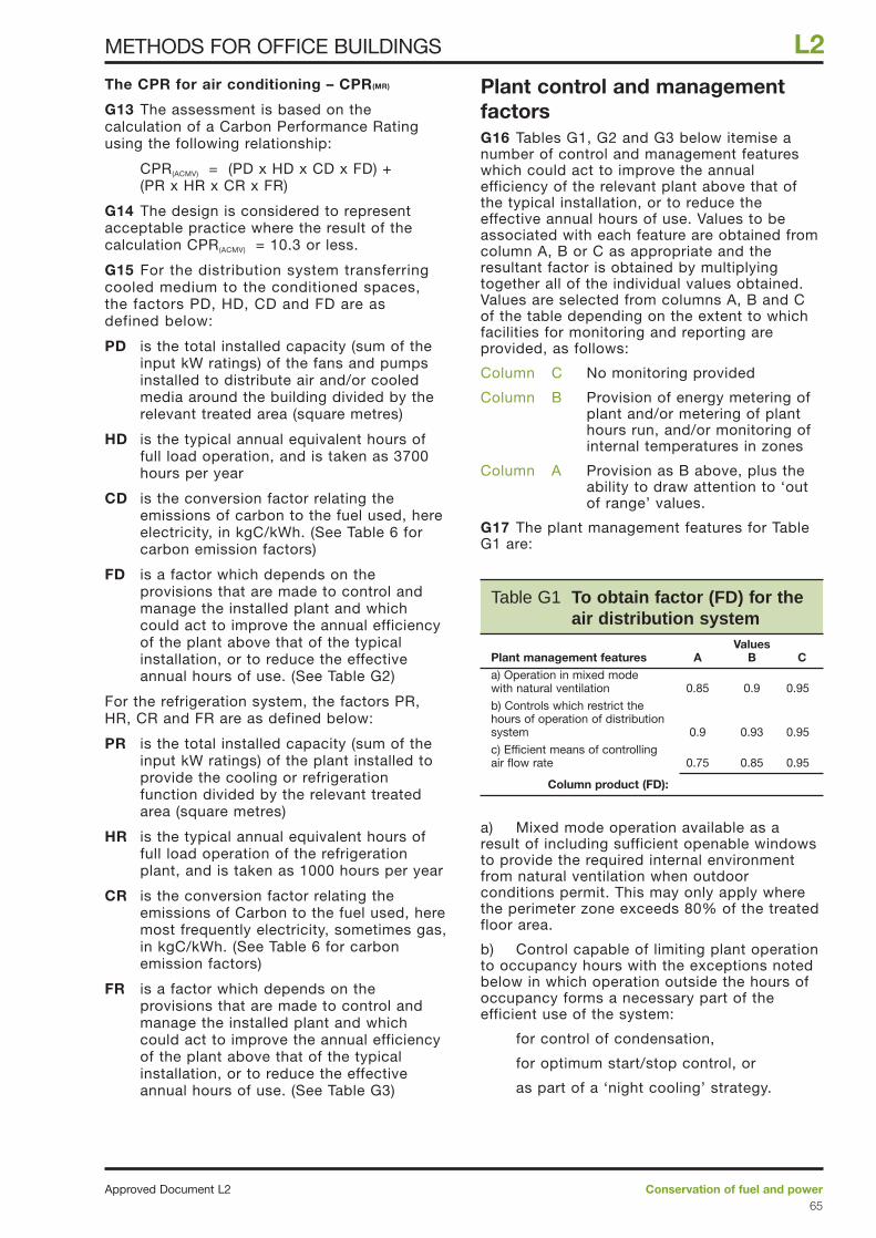
The CPR for air conditioning – CPR(MR)
G13 The assessment is based on thecalculation of a Carbon Performance Ratingusing the following relationship:
CPR(ACMV) = (PD x HD x CD x FD) +(PR x HR x CR x FR)
G14 The design is considered to representacceptable practice where the result of thecalculation CPR(ACMV) = 10.3 or less.
G15 For the distribution system transferringcooled medium to the conditioned spaces,the factors PD, HD, CD and FD are asdefined below:
PD is the total installed capacity (sum of theinput kW ratings) of the fans and pumpsinstalled to distribute air and/or cooledmedia around the building divided by therelevant treated area (square metres)
HD is the typical annual equivalent hours offull load operation, and is taken as 3700hours per year
CD is the conversion factor relating theemissions of carbon to the fuel used, hereelectricity, in kgC/kWh. (See Table 6 forcarbon emission factors)
FD is a factor which depends on theprovisions that are made to control andmanage the installed plant and whichcould act to improve the annual efficiencyof the plant above that of the typicalinstallation, or to reduce the effectiveannual hours of use. (See Table G2)
For the refrigeration system, the factors PR,HR, CR and FR are as defined below:
PR is the total installed capacity (sum of theinput kW ratings) of the plant installed toprovide the cooling or refrigerationfunction divided by the relevant treatedarea (square metres)
HR is the typical annual equivalent hours offull load operation of the refrigerationplant, and is taken as 1000 hours per year
CR is the conversion factor relating theemissions of Carbon to the fuel used, heremost frequently electricity, sometimes gas,in kgC/kWh. (See Table 6 for carbonemission factors)
FR is a factor which depends on theprovisions that are made to control andmanage the installed plant and whichcould act to improve the annual efficiencyof the plant above that of the typicalinstallation, or to reduce the effectiveannual hours of use. (See Table G3)
Plant control and managementfactorsG16 Tables G1, G2 and G3 below itemise anumber of control and management featureswhich could act to improve the annualefficiency of the relevant plant above that ofthe typical installation, or to reduce theeffective annual hours of use. Values to beassociated with each feature are obtained fromcolumn A, B or C as appropriate and theresultant factor is obtained by multiplyingtogether all of the individual values obtained.Values are selected from columns A, B and Cof the table depending on the extent to whichfacilities for monitoring and reporting areprovided, as follows:
Column C No monitoring provided
Column B Provision of energy metering ofplant and/or metering of planthours run, and/or monitoring ofinternal temperatures in zones
Column A Provision as B above, plus theability to draw attention to ‘outof range’ values.
G17 The plant management features for TableG1 are:
a) Mixed mode operation available as aresult of including sufficient openable windowsto provide the required internal environmentfrom natural ventilation when outdoorconditions permit. This may only apply wherethe perimeter zone exceeds 80% of the treatedfloor area.
b) Control capable of limiting plant operationto occupancy hours with the exceptions notedbelow in which operation outside the hours ofoccupancy forms a necessary part of theefficient use of the system:
for control of condensation,
for optimum start/stop control, or
as part of a ‘night cooling’ strategy.
Conservation of fuel and powerApproved Document L265
L2METHODS FOR OFFICE BUILDINGS
Table G1 To obtain factor (FD) for theair distribution system
ValuesPlant management features A B Ca) Operation in mixed mode with natural ventilation 0.85 0.9 0.95
b) Controls which restrict the hours of operation of distribution system 0.9 0.93 0.95
c) Efficient means of controlling air flow rate 0.75 0.85 0.95
Column product (FD):
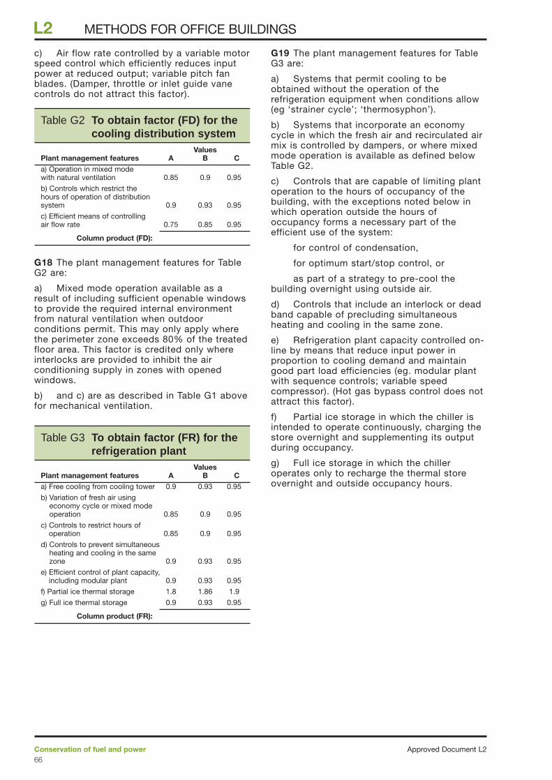
c) Air flow rate controlled by a variable motorspeed control which efficiently reduces inputpower at reduced output; variable pitch fanblades. (Damper, throttle or inlet guide vanecontrols do not attract this factor).
G18 The plant management features for TableG2 are:
a) Mixed mode operation available as aresult of including sufficient openable windowsto provide the required internal environmentfrom natural ventilation when outdoorconditions permit. This may only apply wherethe perimeter zone exceeds 80% of the treatedfloor area. This factor is credited only whereinterlocks are provided to inhibit the airconditioning supply in zones with openedwindows.
b) and c) are as described in Table G1 abovefor mechanical ventilation.
G19 The plant management features for TableG3 are:
a) Systems that permit cooling to beobtained without the operation of therefrigeration equipment when conditions allow(eg ‘strainer cycle’; ‘thermosyphon’).
b) Systems that incorporate an economycycle in which the fresh air and recirculated airmix is controlled by dampers, or where mixedmode operation is available as defined belowTable G2.
c) Controls that are capable of limiting plantoperation to the hours of occupancy of thebuilding, with the exceptions noted below inwhich operation outside the hours ofoccupancy forms a necessary part of theefficient use of the system:
for control of condensation,
for optimum start/stop control, or
as part of a strategy to pre-cool thebuilding overnight using outside air.
d) Controls that include an interlock or deadband capable of precluding simultaneousheating and cooling in the same zone.
e) Refrigeration plant capacity controlled on-line by means that reduce input power inproportion to cooling demand and maintaingood part load efficiencies (eg. modular plantwith sequence controls; variable speedcompressor). (Hot gas bypass control does notattract this factor).
f) Partial ice storage in which the chiller isintended to operate continuously, charging thestore overnight and supplementing its outputduring occupancy.
g) Full ice storage in which the chilleroperates only to recharge the thermal storeovernight and outside occupancy hours.
Approved Document L2Conservation of fuel and power66
L2 METHODS FOR OFFICE BUILDINGS
Table G2 To obtain factor (FD) for thecooling distribution system
ValuesPlant management features A B Ca) Operation in mixed mode with natural ventilation 0.85 0.9 0.95
b) Controls which restrict the hours of operation of distribution system 0.9 0.93 0.95
c) Efficient means of controlling air flow rate 0.75 0.85 0.95
Column product (FD):
Table G3 To obtain factor (FR) for therefrigeration plant
ValuesPlant management features A B Ca) Free cooling from cooling tower 0.9 0.93 0.95
b) Variation of fresh air usingeconomy cycle or mixed modeoperation 0.85 0.9 0.95
c) Controls to restrict hours ofoperation 0.85 0.9 0.95
d) Controls to prevent simultaneousheating and cooling in the same zone 0.9 0.93 0.95
e) Efficient control of plant capacity,including modular plant 0.9 0.93 0.95
f) Partial ice thermal storage 1.8 1.86 1.9
g) Full ice thermal storage 0.9 0.93 0.95
Column product (FR):
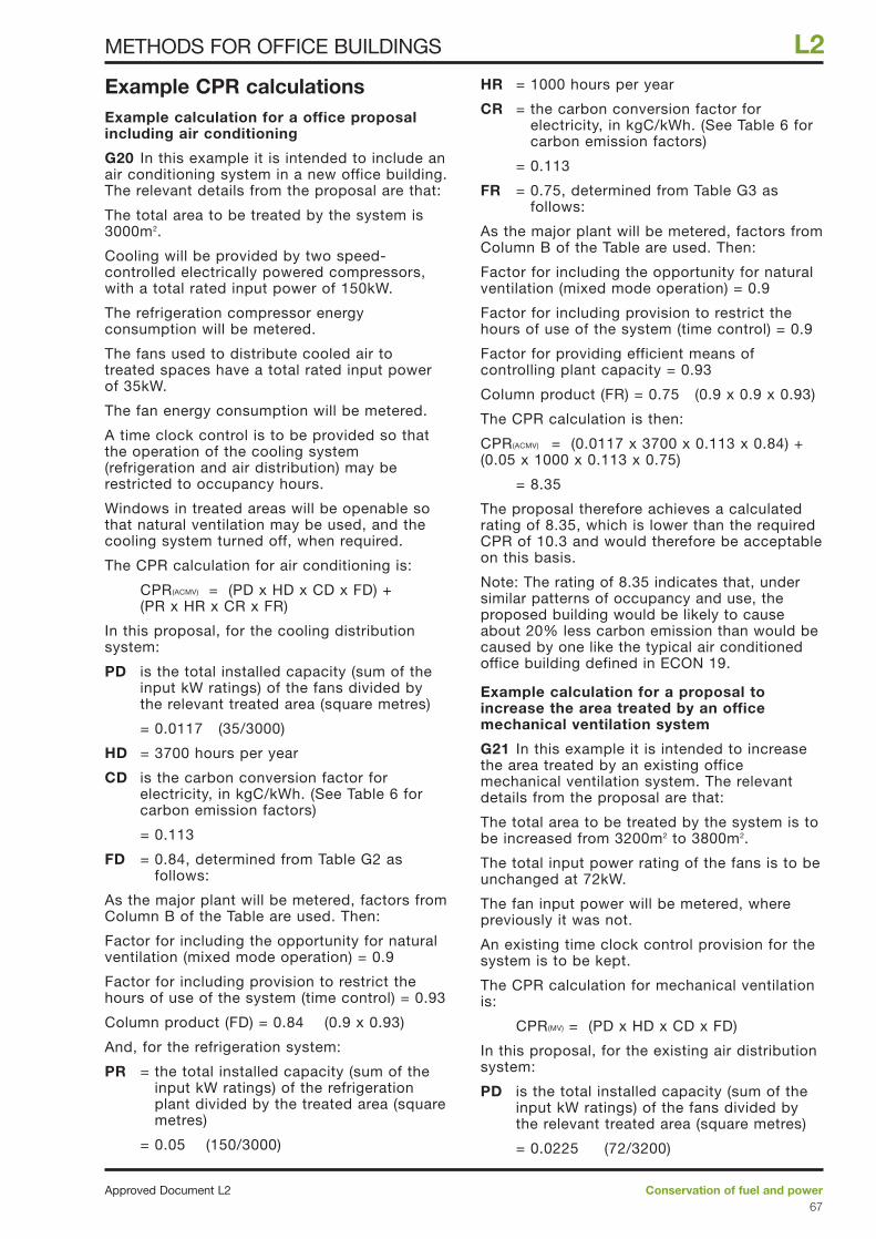
Example CPR calculationsExample calculation for a office proposalincluding air conditioning
G20 In this example it is intended to include anair conditioning system in a new office building.The relevant details from the proposal are that:
The total area to be treated by the system is3000m2.
Cooling will be provided by two speed-controlled electrically powered compressors,with a total rated input power of 150kW.
The refrigeration compressor energyconsumption will be metered.
The fans used to distribute cooled air totreated spaces have a total rated input powerof 35kW.
The fan energy consumption will be metered.
A time clock control is to be provided so thatthe operation of the cooling system(refrigeration and air distribution) may berestricted to occupancy hours.
Windows in treated areas will be openable sothat natural ventilation may be used, and thecooling system turned off, when required.
The CPR calculation for air conditioning is:
CPR(ACMV) = (PD x HD x CD x FD) + (PR x HR x CR x FR)
In this proposal, for the cooling distributionsystem:
PD is the total installed capacity (sum of theinput kW ratings) of the fans divided bythe relevant treated area (square metres)
= 0.0117 (35/3000)
HD = 3700 hours per year
CD is the carbon conversion factor forelectricity, in kgC/kWh. (See Table 6 forcarbon emission factors)
= 0.113
FD = 0.84, determined from Table G2 asfollows:
As the major plant will be metered, factors fromColumn B of the Table are used. Then:
Factor for including the opportunity for naturalventilation (mixed mode operation) = 0.9
Factor for including provision to restrict thehours of use of the system (time control) = 0.93
Column product (FD) = 0.84 (0.9 x 0.93)
And, for the refrigeration system:
PR = the total installed capacity (sum of theinput kW ratings) of the refrigerationplant divided by the treated area (squaremetres)
= 0.05 (150/3000)
HR = 1000 hours per year
CR = the carbon conversion factor forelectricity, in kgC/kWh. (See Table 6 forcarbon emission factors)
= 0.113
FR = 0.75, determined from Table G3 asfollows:
As the major plant will be metered, factors fromColumn B of the Table are used. Then:
Factor for including the opportunity for naturalventilation (mixed mode operation) = 0.9
Factor for including provision to restrict thehours of use of the system (time control) = 0.9
Factor for providing efficient means ofcontrolling plant capacity = 0.93
Column product (FR) = 0.75 (0.9 x 0.9 x 0.93)
The CPR calculation is then:
CPR(ACMV) = (0.0117 x 3700 x 0.113 x 0.84) +(0.05 x 1000 x 0.113 x 0.75)
= 8.35
The proposal therefore achieves a calculatedrating of 8.35, which is lower than the requiredCPR of 10.3 and would therefore be acceptableon this basis.
Note: The rating of 8.35 indicates that, undersimilar patterns of occupancy and use, theproposed building would be likely to causeabout 20% less carbon emission than would becaused by one like the typical air conditionedoffice building defined in ECON 19.
Example calculation for a proposal toincrease the area treated by an officemechanical ventilation system
G21 In this example it is intended to increasethe area treated by an existing officemechanical ventilation system. The relevantdetails from the proposal are that:
The total area to be treated by the system is tobe increased from 3200m2 to 3800m2.
The total input power rating of the fans is to beunchanged at 72kW.
The fan input power will be metered, wherepreviously it was not.
An existing time clock control provision for thesystem is to be kept.
The CPR calculation for mechanical ventilationis:
CPR(MV) = (PD x HD x CD x FD)
In this proposal, for the existing air distributionsystem:
PD is the total installed capacity (sum of theinput kW ratings) of the fans divided bythe relevant treated area (square metres)
= 0.0225 (72/3200)
Conservation of fuel and powerApproved Document L267
L2METHODS FOR OFFICE BUILDINGS

HD = 3700 hours per year
CD is the carbon conversion factor forelectricity, in kgC/kWh. (See Table 6 forcarbon emission factors)
= 0.113
FD = 0.95, determined from Table G1 asfollows:
As the plant is not metered, factors fromColumn C of the Table are used. Then:
Factor for including provision to restrict thehours of use of the system (time control) = 0.95
Column product (FD) = 0.95
The CPR calculation is then:
CPR(MV) = (0.0225 x 3700 x 0.113 x 0.95) = 8.94
Since this calculated rating of 8.94 for theexisting system is higher than the target 6.5 fornew construction, the altered system would berequired to reduce the rating by 10%, or to7.15 (6.5+10%), whichever is the lessdemanding. In this case the 10% reduction isthe less demanding and results in a targetrating of 8.04.
In this proposal, for the extended airdistribution system:
PD is the total installed capacity (sum of theinput kW ratings) of the fans divided bythe relevant treated area (square metres)
= 0.01895 (72/3800)
HD = 3700 hours per year
CD is the carbon conversion factor forelectricity, in kgC/kWh. (See Table 6 forcarbon emission factors)
= 0.113
FD = 0.93, determined from Table G1 asfollows:
As plant will now be metered, factors fromColumn B of the Table are used, then:
Factor for including provision to restrict thehours of use of the system (time control) = 0.93
Column product (FD) = 0.93
The CPR calculation is then:
CPR(MV) = (0.01895 x 3700 x 0.113 x 0.93)= 7.37
This alteration achieves a rating lower than itsparticular target of 8.04 and would therefore beacceptable on this basis.
Note: The rating of 7.37 indicates that, undersimilar patterns of occupancy and use, theproposed building would be likely to causeabout 13% greater carbon emission than onelike the typical air conditioned office buildingdefined in ECON 19.
Example calculation for a office proposalincluding air conditioning and a dedicated,air conditioned, computer suite.
G22 In this example it is intended to include anair conditioning system in a new office buildingthat also houses a dedicated computer suitethat will be served as a separate controlledzone from the centralised air conditioningsystem. The relevant details from the proposalare that:
The total area to be treated by the system is3500m2.
Cooling will be provided by two speed-controlled electrically powered compressors,with a total rated input power of 225kW.
The refrigeration compressor energyconsumption will be metered.
The fans used to distribute cooled air totreated spaces have a total rated input powerof 45kW.
The fan energy consumption will be metered.
Windows in treated office areas will beopenable, with interlocks to disable the localair conditioning terminals, so that naturalventilation may be used when required.
Efficient fan speed control will be installed toaccommodate the variations in demand for airsupply.
The treated area of the computer room is500m2. The designer has estimated that therefrigeration input power required to service thecomputer room is 45kW and the fan inputpower required to provide air supply to thecomputer room is 10kW.
The relevant plant input power ratings and therelevant treated area are the result ofsubtracting the computer room area and theplant required to service it from the totals,hence:
Relevant treated area = 3000m2
(3500 – 500)
Relevant refrigeration installed capacity = 180kW (225 – 45)
Relevant fan installed capacity = 35kW (45 – 10)
The CPR calculation for air conditioning is:
CPR(ACMV) = (PD x HD x CD x FD) + (PR x HR x CR x FR)
In this proposal, for the cooling distributionsystem:
PD is the total installed capacity (sum of theinput kW ratings) of the fans divided bythe relevant treated area (square metres)
= 0.0117 (35/3000)
HD = 3700 hours per year
Approved Document L2Conservation of fuel and power68
L2 METHODS FOR OFFICE BUILDINGS
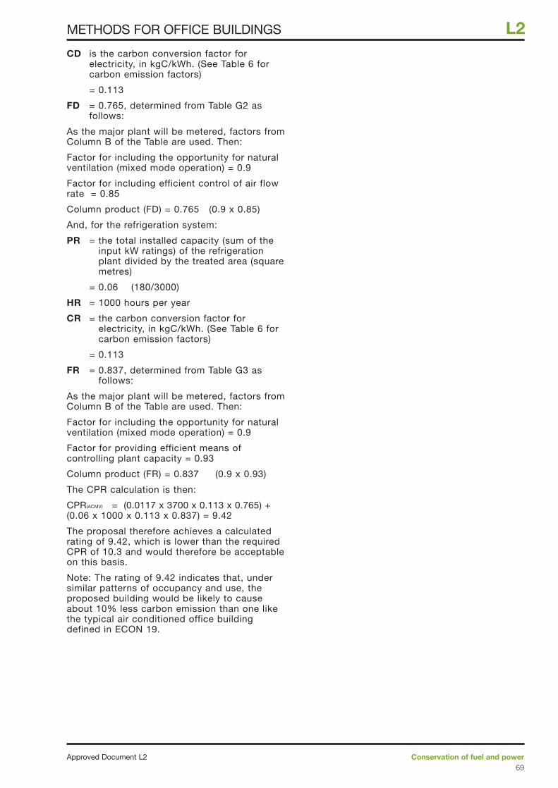
CD is the carbon conversion factor forelectricity, in kgC/kWh. (See Table 6 forcarbon emission factors)
= 0.113
FD = 0.765, determined from Table G2 asfollows:
As the major plant will be metered, factors fromColumn B of the Table are used. Then:
Factor for including the opportunity for naturalventilation (mixed mode operation) = 0.9
Factor for including efficient control of air flowrate = 0.85
Column product (FD) = 0.765 (0.9 x 0.85)
And, for the refrigeration system:
PR = the total installed capacity (sum of theinput kW ratings) of the refrigerationplant divided by the treated area (squaremetres)
= 0.06 (180/3000)
HR = 1000 hours per year
CR = the carbon conversion factor forelectricity, in kgC/kWh. (See Table 6 forcarbon emission factors)
= 0.113
FR = 0.837, determined from Table G3 asfollows:
As the major plant will be metered, factors fromColumn B of the Table are used. Then:
Factor for including the opportunity for naturalventilation (mixed mode operation) = 0.9
Factor for providing efficient means ofcontrolling plant capacity = 0.93
Column product (FR) = 0.837 (0.9 x 0.93)
The CPR calculation is then:
CPR(ACMV) = (0.0117 x 3700 x 0.113 x 0.765) +(0.06 x 1000 x 0.113 x 0.837) = 9.42
The proposal therefore achieves a calculatedrating of 9.42, which is lower than the requiredCPR of 10.3 and would therefore be acceptableon this basis.
Note: The rating of 9.42 indicates that, undersimilar patterns of occupancy and use, theproposed building would be likely to causeabout 10% less carbon emission than one likethe typical air conditioned office buildingdefined in ECON 19.
Conservation of fuel and powerApproved Document L269
L2METHODS FOR OFFICE BUILDINGS
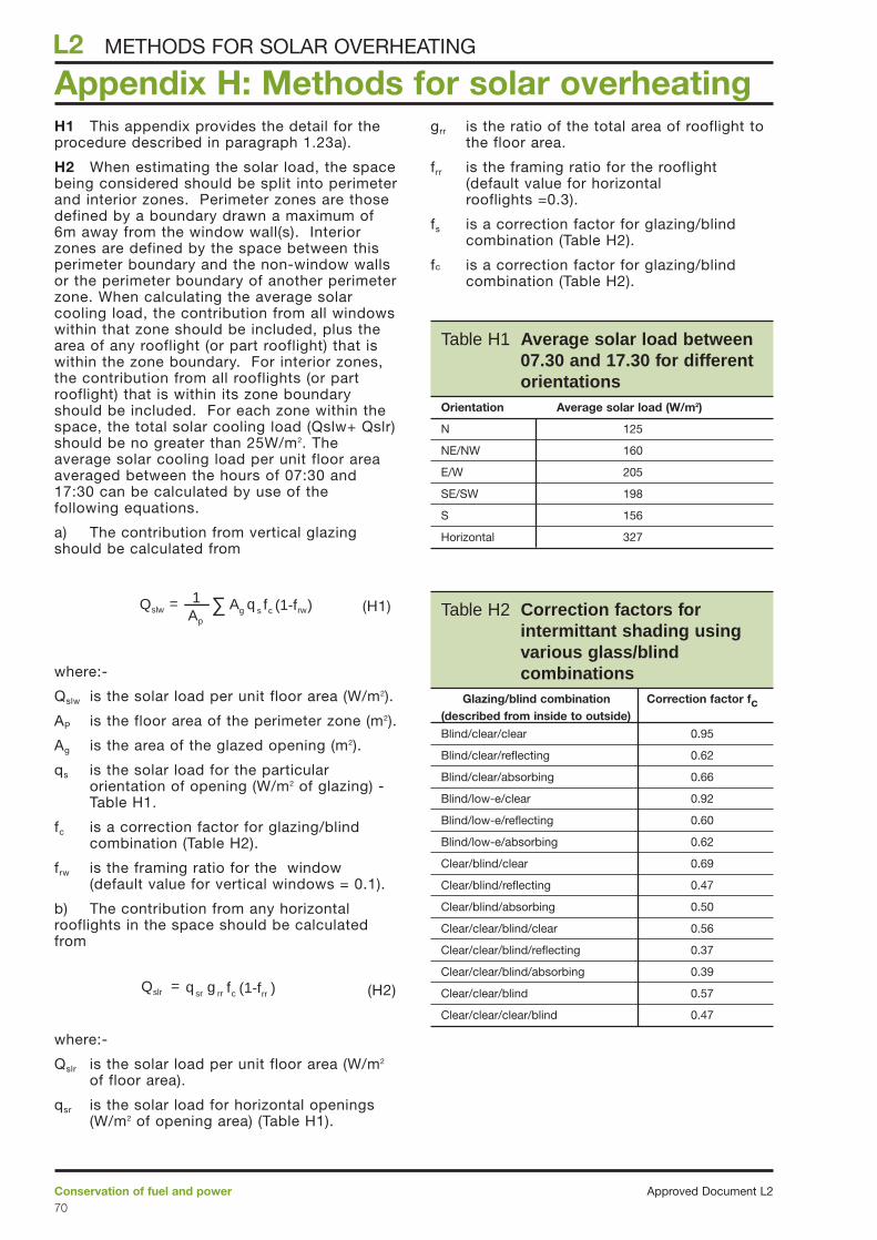
H1 This appendix provides the detail for theprocedure described in paragraph 1.23a).
H2 When estimating the solar load, the spacebeing considered should be split into perimeterand interior zones. Perimeter zones are thosedefined by a boundary drawn a maximum of6m away from the window wall(s). Interiorzones are defined by the space between thisperimeter boundary and the non-window wallsor the perimeter boundary of another perimeterzone. When calculating the average solarcooling load, the contribution from all windowswithin that zone should be included, plus thearea of any rooflight (or part rooflight) that iswithin the zone boundary. For interior zones,the contribution from all rooflights (or partrooflight) that is within its zone boundaryshould be included. For each zone within thespace, the total solar cooling load (Qslw+ Qslr)should be no greater than 25W/m2. Theaverage solar cooling load per unit floor areaaveraged between the hours of 07:30 and17:30 can be calculated by use of thefollowing equations.
a) The contribution from vertical glazingshould be calculated from
(H1)
where:-
Qslw is the solar load per unit floor area (W/m2).
AP is the floor area of the perimeter zone (m2).
Ag is the area of the glazed opening (m2).
qs is the solar load for the particularorientation of opening (W/m2 of glazing) -Table H1.
fc is a correction factor for glazing/blindcombination (Table H2).
frw is the framing ratio for the window(default value for vertical windows = 0.1).
b) The contribution from any horizontalrooflights in the space should be calculatedfrom
(H2)
where:-
Qslr is the solar load per unit floor area (W/m2
of floor area).
qsr is the solar load for horizontal openings(W/m2 of opening area) (Table H1).
grr is the ratio of the total area of rooflight tothe floor area.
frr is the framing ratio for the rooflight(default value for horizontalrooflights =0.3).
fs is a correction factor for glazing/blindcombination (Table H2).
fc is a correction factor for glazing/blindcombination (Table H2).
= q sr g rr fc (1-frr )Qslr
1= ∑Ap
Ag q s fc (1-frw)Qslw
Approved Document L2Conservation of fuel and power70
L2
Appendix H: Methods for solar overheating METHODS FOR SOLAR OVERHEATING
Table H2 Correction factors forintermittant shading usingvarious glass/blindcombinations
Glazing/blind combination Correction factor fc(described from inside to outside)
Blind/clear/clear 0.95
Blind/clear/reflecting 0.62
Blind/clear/absorbing 0.66
Blind/low-e/clear 0.92
Blind/low-e/reflecting 0.60
Blind/low-e/absorbing 0.62
Clear/blind/clear 0.69
Clear/blind/reflecting 0.47
Clear/blind/absorbing 0.50
Clear/clear/blind/clear 0.56
Clear/clear/blind/reflecting 0.37
Clear/clear/blind/absorbing 0.39
Clear/clear/blind 0.57
Clear/clear/clear/blind 0.47
Table H1 Average solar load between07.30 and 17.30 for differentorientations
Orientation Average solar load (W/m2)
N 125
NE/NW 160
E/W 205
SE/SW 198
S 156
Horizontal 327
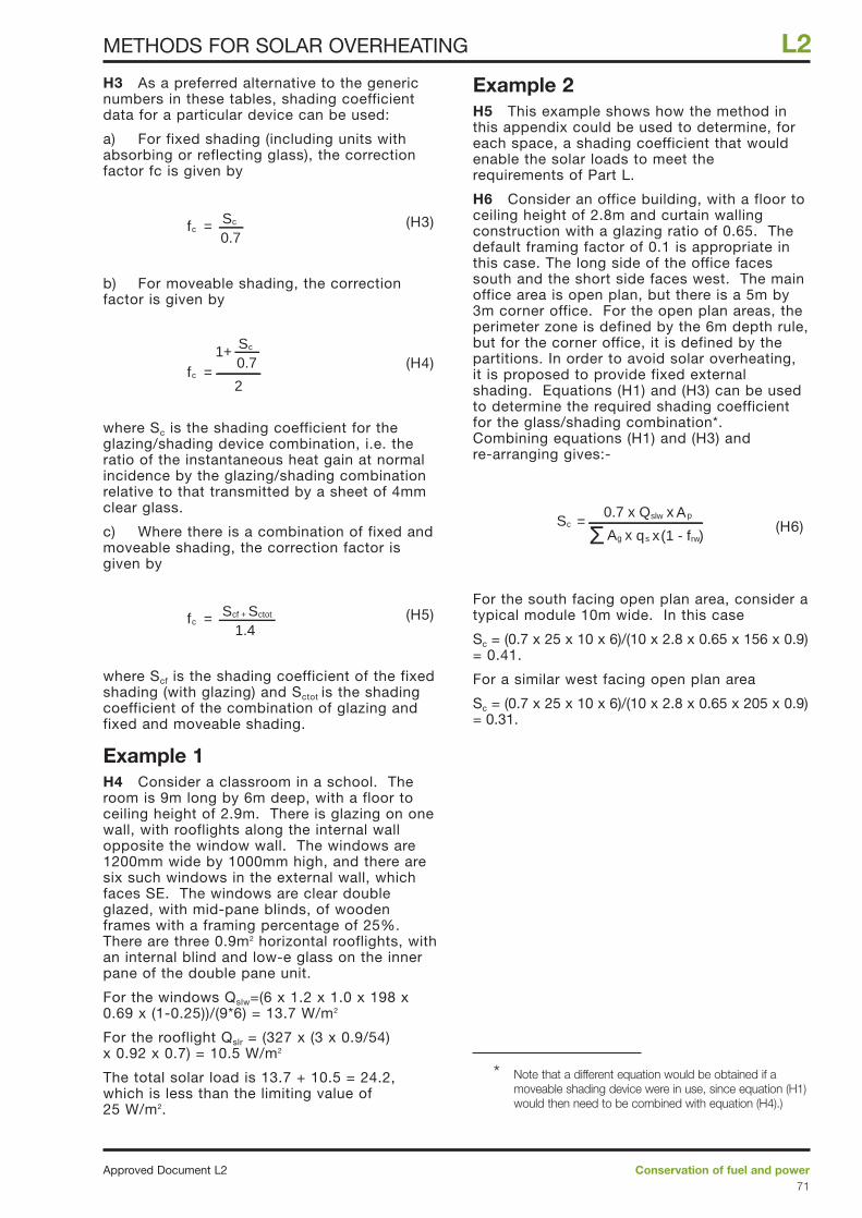
H3 As a preferred alternative to the genericnumbers in these tables, shading coefficientdata for a particular device can be used:
a) For fixed shading (including units withabsorbing or reflecting glass), the correctionfactor fc is given by
(H3)
b) For moveable shading, the correctionfactor is given by
(H4)
where Sc is the shading coefficient for theglazing/shading device combination, i.e. theratio of the instantaneous heat gain at normalincidence by the glazing/shading combinationrelative to that transmitted by a sheet of 4mmclear glass.
c) Where there is a combination of fixed andmoveable shading, the correction factor isgiven by
(H5)
where Scf is the shading coefficient of the fixedshading (with glazing) and Sctot is the shadingcoefficient of the combination of glazing andfixed and moveable shading.
Example 1H4 Consider a classroom in a school. Theroom is 9m long by 6m deep, with a floor toceiling height of 2.9m. There is glazing on onewall, with rooflights along the internal wallopposite the window wall. The windows are1200mm wide by 1000mm high, and there aresix such windows in the external wall, whichfaces SE. The windows are clear doubleglazed, with mid-pane blinds, of woodenframes with a framing percentage of 25%.There are three 0.9m2 horizontal rooflights, withan internal blind and low-e glass on the innerpane of the double pane unit.
For the windows Qslw=(6 x 1.2 x 1.0 x 198 x0.69 x (1-0.25))/(9*6) = 13.7 W/m2
For the rooflight Qslr = (327 x (3 x 0.9/54) x 0.92 x 0.7) = 10.5 W/m2
The total solar load is 13.7 + 10.5 = 24.2,which is less than the limiting value of25 W/m2.
Example 2H5 This example shows how the method inthis appendix could be used to determine, foreach space, a shading coefficient that wouldenable the solar loads to meet therequirements of Part L.
H6 Consider an office building, with a floor toceiling height of 2.8m and curtain wallingconstruction with a glazing ratio of 0.65. Thedefault framing factor of 0.1 is appropriate inthis case. The long side of the office facessouth and the short side faces west. The mainoffice area is open plan, but there is a 5m by3m corner office. For the open plan areas, theperimeter zone is defined by the 6m depth rule,but for the corner office, it is defined by thepartitions. In order to avoid solar overheating,it is proposed to provide fixed externalshading. Equations (H1) and (H3) can be usedto determine the required shading coefficientfor the glass/shading combination*.Combining equations (H1) and (H3) andre-arranging gives:-
(H6)
For the south facing open plan area, consider atypical module 10m wide. In this case
Sc = (0.7 x 25 x 10 x 6)/(10 x 2.8 x 0.65 x 156 x 0.9)= 0.41.
For a similar west facing open plan area
Sc = (0.7 x 25 x 10 x 6)/(10 x 2.8 x 0.65 x 205 x 0.9)= 0.31.
= 0.7 x Q xSc
Σslw Ap
A xg q xs (1 - f )rw
=1.4
fcScf + Sctot
= 0.7fc
Sc1+
2
=0.7
fcSc
Conservation of fuel and powerApproved Document L271
L2METHODS FOR SOLAR OVERHEATING
* Note that a different equation would be obtained if amoveable shading device were in use, since equation (H1)would then need to be combined with equation (H4).)
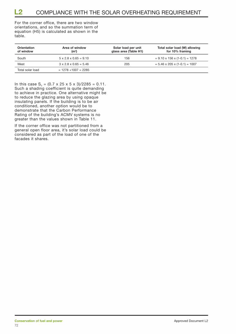
For the corner office, there are two windoworientations, and so the summation term ofequation (H5) is calculated as shown in thetable.
In this case Sc = (0.7 x 25 x 5 x 3)/2285 = 0.11.Such a shading coefficient is quite demandingto achieve in practice. One alternative might beto reduce the glazing area by using opaqueinsulating panels. If the building is to be airconditioned, another option would be todemonstrate that the Carbon PerformanceRating of the building’s ACMV systems is nogreater than the values shown in Table 11.
If the corner office was not partitioned from ageneral open floor area, it’s solar load could beconsidered as part of the load of one of thefacades it shares.
Approved Document L2Conservation of fuel and power72
L2 COMPLIANCE WITH THE SOLAR OVERHEATING REQUIREMENT
Orientation Area of window Solar load per unit Total solar load (W) allowingof window (m2) glass area (Table H1) for 10% framing
South 5 x 2.8 x 0.65 = 9.10 156 = 9.10 x 156 x (1-0.1) = 1278
West 3 x 2.8 x 0.65 = 5.46 205 = 5.46 x 205 x (1-0.1) = 1007
Total solar load = 1278 +1007 = 2285
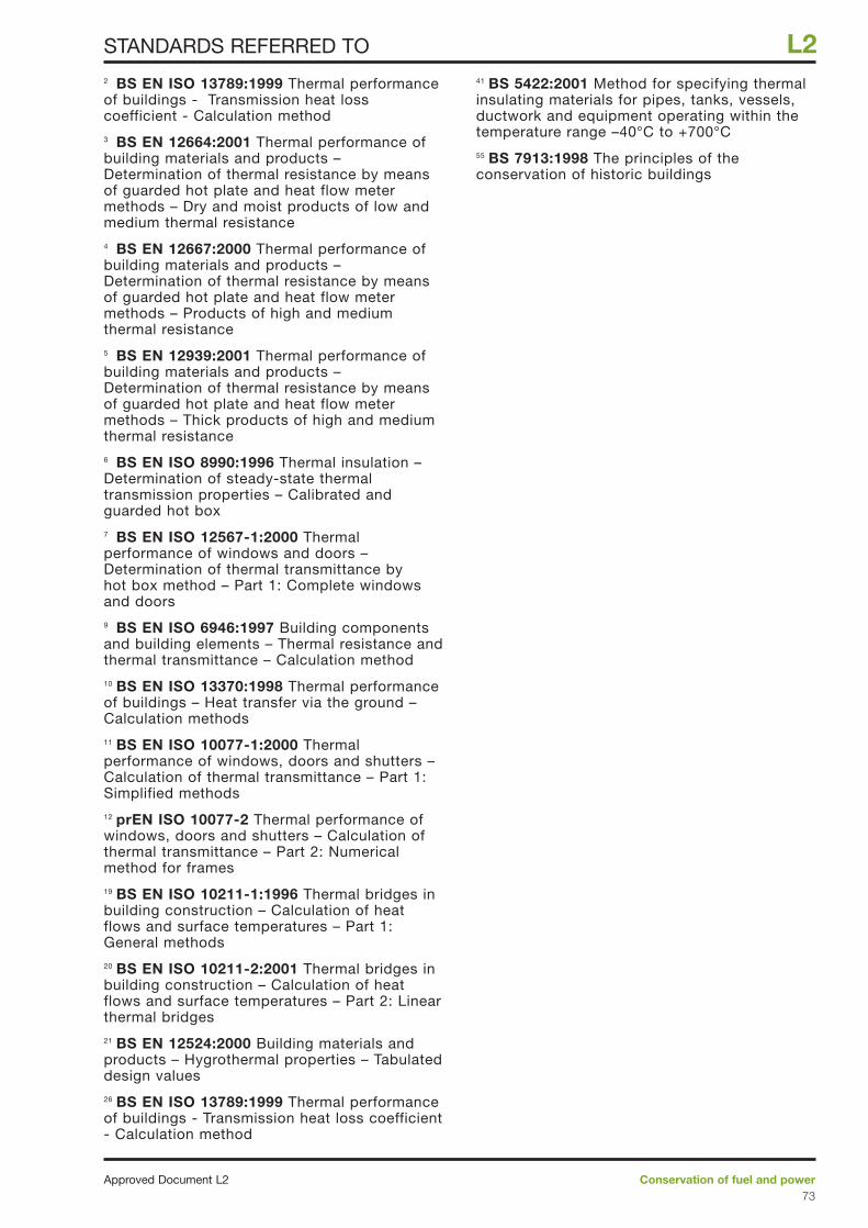
2 BS EN ISO 13789:1999 Thermal performanceof buildings - Transmission heat losscoefficient - Calculation method3 BS EN 12664:2001 Thermal performance ofbuilding materials and products –Determination of thermal resistance by meansof guarded hot plate and heat flow metermethods – Dry and moist products of low andmedium thermal resistance4 BS EN 12667:2000 Thermal performance ofbuilding materials and products –Determination of thermal resistance by meansof guarded hot plate and heat flow metermethods – Products of high and mediumthermal resistance5 BS EN 12939:2001 Thermal performance ofbuilding materials and products –Determination of thermal resistance by meansof guarded hot plate and heat flow metermethods – Thick products of high and mediumthermal resistance6 BS EN ISO 8990:1996 Thermal insulation –Determination of steady-state thermaltransmission properties – Calibrated andguarded hot box7 BS EN ISO 12567-1:2000 Thermalperformance of windows and doors –Determination of thermal transmittance byhot box method – Part 1: Complete windowsand doors9 BS EN ISO 6946:1997 Building componentsand building elements – Thermal resistance andthermal transmittance – Calculation method10 BS EN ISO 13370:1998 Thermal performanceof buildings – Heat transfer via the ground –Calculation methods11 BS EN ISO 10077-1:2000 Thermalperformance of windows, doors and shutters –Calculation of thermal transmittance – Part 1:Simplified methods12 prEN ISO 10077-2 Thermal performance ofwindows, doors and shutters – Calculation ofthermal transmittance – Part 2: Numericalmethod for frames19 BS EN ISO 10211-1:1996 Thermal bridges inbuilding construction – Calculation of heatflows and surface temperatures – Part 1:General methods20 BS EN ISO 10211-2:2001 Thermal bridges inbuilding construction – Calculation of heatflows and surface temperatures – Part 2: Linearthermal bridges21 BS EN 12524:2000 Building materials andproducts – Hygrothermal properties – Tabulateddesign values26 BS EN ISO 13789:1999 Thermal performanceof buildings - Transmission heat loss coefficient- Calculation method
41 BS 5422:2001 Method for specifying thermalinsulating materials for pipes, tanks, vessels,ductwork and equipment operating within thetemperature range –40°C to +700°C55 BS 7913:1998 The principles of theconservation of historic buildings
Conservation of fuel and powerApproved Document L273
L2STANDARDS REFERRED TO
The Stationery Office1, 27 Limiting thermal bridging and air leakage:Robust construction details for dwellings andsimilar buildings, TSO 200147 Guidelines for environmental design inschools, Building Bulletin 87, TSO, 1997.48 NHS Estates: Achieving energy efficiency innew hospitals, TSO, 1994.
British Cement Association (BCA) andNational House Building Council (NHBC)12, 21 Approved Document – Basements fordwellings, 1997, ISBN 0-7210-1508-5
Building Research Energy ConservationSupport Unit (BRECSU)34 GIR 31, 1995 Avoiding or minimising the useof air-conditioning 38 GPG 303, 2000 The designer’s guide toenergy-efficient buildings for industry.39 GPG 132, 2001 Heating controls in smallcommercial and multi-residential buildings45 GIR 41, 1996 Variable flow control53 GIL 65, 2001 Sub-metering New Build Non-domestic Buildings: A guide to help buildingdesigners meet Part L of the BuildingRegulations.
Building Research Establishment (BRE)(published by CRC Ltd)8 Conventions for the calculation of U-values:expected publication date early 200214 IP 5/98 Metal cladding: assessing thermalperformance18 U-value calculation procedure for light steelframe walls: expected publication date early200228 IP 17/01 Assessing the effects of thermalbridging at junctions and around openings30 BR 262, 2002 Edition Thermal insulation:avoiding risks, 33 BR 364, 1999 Solar shading of buildings43 IP 2/99 Photoelectric control of lighting:design, set-up and installation issues 46 Digest 457, 2001, The Carbon PerformanceRating for offices, 50 BR 176, 1991 A practical guide to infra-redthermography for building surveys,.
Centre for Window and Cladding Technology(CWCT)16 Guide to good practice for assessing glazingframe U-values (1998, new edition inpreparation)17 Guide to good practice for assessing heattransfer and condensation risk for a curtainwall (1998, new edition in preparation)
Chartered Institution of Building ServicesEngineers (CIBSE)22 Guide A: Environmental design, Section A3:Thermal properties of building structures, 199924 Energy efficiency in buildings, 199831 LG10: Daylight and window design, 199935 Guide A: Environmental Design, Section A5:Thermal response and plant sizing, 1999.40 Guide H: Building Control Systems, 200044 TM22: Energy Assessment and ReportingMethodology: Office Assessment Method, 199949 AM11; Building Energy and EnvironmentalModelling, 199851 TM23: Testing buildings for air leakage, 200054 Energy Efficiency in Buildings, Chapter 11:General electric power, 1998
Commissioning Specialists Association52 Technical Memorandum 1: Standardspecification for the commissioning ofmechanical engineering services installationsfor buildings, 1999
Council for Aluminium in Building (CAB)15 Guide for assessment of the thermalperformance of aluminium curtain wall framing,1996
Department of the Environment (DoE) andDepartment for National Heritage (DNH)23 Planning and the historic environment,Planning Policy Guidance PPG 15, DoE/DNH,September 1994. (In Wales refer to PlanningGuidance Wales Planning Policy First Revision1999 and Welsh Office Circular 61/96 Planningand Historic Environment: Historic Buildingsand Conservation Areas.)
Department of the Environment, Transportand the Regions (DETR)25 Energy Consumption Guide 19: Energy use inoffices-, 199837 CHPQA Standard: Quality Assurance forCombined Heat and Power, Issue 1, November2000.
Metal Cladding and Roofing ManufacturersAssociation (MCRMA)29 Technical Note 14: Guidance for the designof metal cladding and roofing to comply withApproved Document L 2002 Edition:
Society for the Protection of AncientBuildings (SPAB)56 Information sheet 4: The need for oldbuildings to breathe, 1986.
Approved Document L2Conservation of fuel and power74
L2 OTHER PUBLICATIONS REFERRED TO

Conservation of fuel and powerApproved Document L275
L2