Embed Size (px)
Citation preview

Building Metering Guide
Rev. 06-18-2012 1
The
California
State
University Office of the Chancellor
Building Metering Guide

Building Metering Guide
Rev. 06-18-2012 2
Acknowledgement
The California State University (CSU) gratefully acknowledges the effort and work of Jai
Agaram, Douglas Effenberger, Paulo Fundament, Richard Henrikson, Malcolm Lewis, Kent
Peterson, Steven Taylor and Satinder Gulati. Comments or inquiries may be directed to:
The California State University
Office of the Chancellor
Capital Planning Design and Construction
Long Beach, California
Attention: Thomas Kennedy, Chief Architecture and Engineering
Telephone: (562) 951-4129
E-mail: [email protected]

Building Metering Guide
Rev. 06-18-2012 3
INDEX
1 Introduction ______________________________________________________ 5
2 What to Meter _____________________________________________________ 6
3 Metering Devices __________________________________________________ 8
3.1 Metering Selection Criteria ______________________________________ 8
3.2 Electric Power Meters __________________________________________ 9
A. Metering System __________________________________________ 9
B. Metering Fundamentals ____________________________________ 9
C. Meter Types _____________________________________________ 11
D. Instrument Transformers __________________________________ 13
3.3 Natural Gas ___________________________________________________ 14
A. Meter Types _____________________________________________ 14
B. Adjustment for Pressure and Temperature ___________________ 17
3.4 Hot Water and Chilled Water ___________________________________ 18
A. BTU Calculation __________________________________________ 18
B. BTU Meters _____________________________________________ 19
C. Flow Meters _____________________________________________ 20
D. Temperature Sensors _____________________________________ 25
3.5 Steam ________________________________________________________ 26
3.6 Domestic Water _______________________________________________ 28
A. Meter Types _____________________________________________ 28
B. Selecting a Meter _________________________________________ 31
C. Meter Installation _________________________________________ 31
3.7 Sewage _______________________________________________________ 32
4 Commissioning and Calibration ___________________________________ 33
4.1 Definitions ____________________________________________________ 33
4.2 Installation ____________________________________________________ 33
Building Metering Guide
Rev. 06-18-2012 4
4.3 Practical Accuracy Validation Process __________________________ 33
4.4 Formal Calibration and Validation Process ______________________ 34
5 Specifying Metering ______________________________________________ 35

Building Metering Guide
Rev. 06-18-2012 5
1 INTRODUCTION
The purpose of this Guide is to assist CSU campuses in properly metering of utilities and other
services at each building in the campus. This Guide is the first of a two part series. This part
covers:
What utilities and services must or should be metered
What devices can be used for metering
How are these devices commissioned and calibrated to ensure accurate data
Part 2 will cover how to collect and store metering data and how to analyze and visualize the
data to improve energy efficiency and operations. The reason for breaking the Guides into two
parts is not to imply the second part is less important (it is not) but to allow Part 1 of the Guide
to be published more quickly in response to requests from several CSU campuses.

Building Metering Guide
Rev. 06-18-2012 6
2 WHAT TO METER
Meters can be installed to measure data for several objectives:
For performance evaluation and benchmarking of a building. Measured data are used to
establish baseline energy use, monitor changes in consumption, and to share data with
program managers and designers.
For billing purposes. These meters should be utility revenue grade accuracy and installed
with metering accuracy instrument transformers.
For measurement & verification of a building or building systems. Measured data are
used to identify inefficient operations and validate proper operation of systems during
commissioning and on an ongoing basis.
To initiate demand side management programs. Measured data are used to trigger
demand limiting logic such as setting thermostat setpoints up a few degrees, limiting fan
static pressure in VAV systems, etc.
Table 1 summarizes both minimum and recommended metering requirements for CSU
campuses. It applies to each building on campus unless the campus energy and utilities manager
provides otherwise.

Building Metering Guide
Rev. 06-18-2012 7
Table 1 – CSU Metering Requirements (each Building)
Service Minimum Metering Recommended Metering Remarks
Electricity Whole building Whole building
Submeter lighting
Submeter plug loads
Submeter HVAC
Submeter primary HVAC equipment (e.g. chillers, AHU fans)
Whole building meters shall be revenue quality unless the campus energy and utilities manager gives written approval. Submeters are not required to be revenue-grade.
Natural Gas Whole building Whole building
Submeter each boiler
Submeter each domestic water heater
Whole building meters shall be revenue quality unless the campus energy and utilities manager gives written approval. Sub-meters are not required to be revenue-grade.
Central Plant Chilled and Hot Water
Whole building Whole building A self-contained “BTU” meter is recommended as opposed to using separate flow and temperature sensors because the accuracy is generally better (matched sensors) and data collection is simpler, particularly if energy is being metered for revenue purposes.
Central Plant Steam
Whole building Whole building Revenue grade meters are not required.
Domestic Water Whole building
Meter or submeter irrigation
Whole building
Meter or submeter irrigation
Submeter domestic hot water
Revenue grade meters are not required.
Sewage Not Required Not Required Only should be considered when water use for irrigation or evaporative processes (e.g. cooling towers) are large and utility provides financial credit for reduced sewer burden

Building Metering Guide
Rev. 06-18-2012 8
3 METERING DEVICES
3.1 Metering Selection Criteria
The devices used to meter utility usage must be sufficiently accurate for the application and
should be reliable with minimal periodic maintenance required. The first cost of metering must
also be reasonable. This section discusses meters that are currently available. When there is
more than one option, the plusses and minuses of each option are explained to assist CSU in
making a choice that reasonably balances costs and performance.
Meter Selection is based on many factors including: cost, functionality, data storage and
retrieval, communication, integration into existing facilities data networks, and security. In each
case, a meter is selected for each application after consideration of the following criteria:
Identify the data requirements for the meter. Is the meter measuring the utility for a
recharge account? Is the facility a laboratory or building with sensitive power or other
special requirements? Is the meter going to be used as a sub-meter to monitor a utility
within a building?
Identify compatibility issues and technical criteria. Many campuses have existing
metering systems. Meters should be compatible with the Building Management System
(BMS) or Energy Management & Control System (EMCS) and the data network and
centralized utility management software.
Develop a campus standard for the metering system based on first cost, operation costs,
and operation and maintenance. Meters can be specified with a local display and
communications ports to allow local and remote data retrieval and troubleshooting. Meters
should be installed so they can be easily isolated and removed from service without
impacting building services or network operation. Meters or data acquisition software
should alarm for a meter fault.
Prepare a campus specification or design guideline for use by campus personnel,
Architects and Engineers for the specification, application and procurement of all
utility meters. New meters must comply with the campus standard and design guideline
and integrate seamlessly with BMS, EMCS and utility monitoring software. The completed
installations must include all communications cabling and be commissioned for service.
Prepare acceptance testing and commissioning requirements for new meters. Meter
installations must be verified as working properly before acceptance. Acceptance
testing and commissioning must include confirmation of instrument transformer ratio,
polarity and connections to the meter, sensor ratings and other issues that can affect the data
produced. The meter readings must be validated by a second standard. Controls,
communication and data acquisition must be function tested.

Building Metering Guide
Rev. 06-18-2012 9
3.2 Electric Power Meters
A. Metering System
Electric power meter measurement, power quality analysis and data storage have kept
pace with the advances in solid state components, especially microprocessors, memory
and communication. Data measurement, data storage, data processing and analysis, event
capture, remote data monitoring and retrieval, and remote control are all features that are
readily available from the modern power meter. The modern campus metering system
will consist of the power meter, a secure data communication network, data collection
hardware, data storage, and software for data collection, data analysis, presentation, and
cost allocation. It is recommended that revenue grade power meters and metering
accuracy instrument transformers be installed in buildings whenever possible. Revenue
grade power meters used in combination with metering class instrument transformers will
provide accurate data.
B. Metering Fundamentals
Electric power measurements and calculations for alternating current (AC) circuits are
made in terms of root mean square (RMS) values.
Each of the sine waves shown in Figure 1 below has the exact same RMS value of 1.0
when measured with a true RMS responding meter. If an average responding meter is
used, it will read 0.9 in one case and 0.775 in the other. Only true RMS responding
meters should be used in electric power measurements.
(a) Pure Sine Wave (b) Sine Wave with Third Harmonic Distortion
Figure 1. Effects of Harmonics on a Sine Wave
Power in an AC circuit consists of apparent power (total power), true power (work), and
reactive power (capacitive and inductive power) − see Figure 2. Apparent power is the
sum in quadrature of the true power and reactive power. Power factor is the ratio of true
power divided by apparent power. Power factor is also the cosine of the phase angle,

Building Metering Guide
Rev. 06-18-2012 10
between the voltage across the circuit (or load) and the current through the circuit (or
load).
Figure 2. Power Triangles for Capacitive and Inductive Circuits
Metering electric energy usage requires the measurement of several variables including:
Voltage (V)
Current (A)
Frequency (Hz)
Phase angle between the voltage and current (θ)
Electric energy is measured for both magnitude (kW) and time (hour) and is metered as
kilowatt-hours (kWh) where the constant “k” stands for “kilo” and is a multiplier of
1,000. Electric energy billings typically consist of an energy consumption component
(kWh), a demand component (kW) and power factor (pf) or reactive power component
(kVar).
Electro-mechanical watt-hour-meter technology and nomenclature were developed and
evolved during the twentieth century. The advent and application of solid state
technology to the watt-hour-meter has greatly enhanced the data processing capabilities of
power meters. Electro-mechanical meters measured energy use and demand through
rotation of an induction disk as a result of torque created by the applied voltage, current
and system frequency. A solid state meter converts current and voltage inputs to digital
signals through an analog to digital converter and measures power using microprocessor
based algorithms, calculations and an internal clock. The microprocessor based meter is
also capable of measuring harmonics, event capture and estimating peak demand.
Electric energy parameters such as KW, KVAR, kVA, and power-factor, can be
calculated as follows:
kW = AV cosine θ (True Power for single phase loads)
kW = AV3 cosine θ (True Power for three phase loads)

Building Metering Guide
Rev. 06-18-2012 11
kVAR = AV3 sine θ (Reactive Power for three phase loads)
Power factor = cosine θ (True Power)÷(Apparent Power)
kVA = (kw2+kVAR
2) ½ (Apparent Power for three phase loads)
C. Meter Types
The most basic energy meters provide energy and demand information. More
sophisticated meters provide information on power quality, capture events, log and store
data, display data through a local screen and communicate with or control other devices
or systems. Meters can be grouped into several categories based on their capabilities:
revenue grade meters advanced energy meters, and sub-meters.
Meters can be installed as socket-mount, semi-flush switch board case style, or on panels
in cabinets. Meters should be installed indoors in a dry conditioned space, such as an
indoor service entrance switchboard room, whenever possible. Other factors to consider
include the proximity to a data network gateway, Modbus, BACnet or other network
communication to a building BMS, EMCS, as well as sub-meter locations and other
communication requirements.
Power meters are available in several ampere rating classes. The class designation
denotes the maximum load capacities (in amperes) of the meter. The classes typically
used include 2, 10, 20,100, 200 and 320. Class 2, 10 and 20 meters are intended to be
used with current transformer (CT) and potential transformer (PT) inputs while Class 100,
200 and 320 meters are direct reading requiring no current transformers. Class 100 and
200 meters are limited to 480V circuits rated no more than 100 A, 200 A and 320A
respectively. In general, voltage transformers are required for circuit applications where
the voltage exceeds 600V. Consult with the meter manufacturer or the meter specification
data sheet for input requirements and limitations.
Power meters are also rated in terms of accuracy. Metering accuracy should be a
minimum of 1% where used for billing purposes. Meters with accuracy classifications
better than 1% are readily available at reasonable cost. ANSI Standard C12.10, Code for
Electricity Metering lists metering accuracy requirements and applications. In general,
except for campus service entrance, certified revenue grade meters are not required to be
installed on CSU installations. However, revenue grade meters are readily available that
are cost competitive with the non-revenue grade type. Revenue grade and metering
accuracy class instrument transformers should be specified for campus power distribution
and building service entrance meters whenever possible. The total accuracy of any meter
installation depends on the accuracy of the meter and also the accuracy of the instrument
transformers.

Building Metering Guide
Rev. 06-18-2012 12
Table 2 – Typical Meter Capabilities By Type
Capability Revenue Grade Meter Advanced Energy
Meter
Sub-meter
Configuration Utility Socket, Panel,
Switchboard
Utility Socket, Panel,
Switchboard
Panel Stand-alone
Revenue Accuracy Yes Yes Not Typical
Energy and Demand Yes Yes Yes
Power Quality Analysis No Yes No
Data Logging Optional Yes Optional
Data Output
And Communications
Pulse RS-232/485 Fiber Optic Wireless Modem
Ethernet TCP/IP
Modbus, BACnet
DNP3.0
Pulse RS-232/485 Fiber Optic Wireless Modem
Ethernet TCP/IP
Modbus, BACnet
DNP3.0
Pulse RS-232 Modem
Modbus, BACnet
Alarm and Control No Yes No
Programmable Input Connections
No Yes No
Graphic Display No Yes Not Typical
Cost $800-$2,000 $2,000 - $5,000 $600-$1,200
Figure 3. Typical Socket Based Meter
Building Metering Guide
Rev. 06-18-2012 13
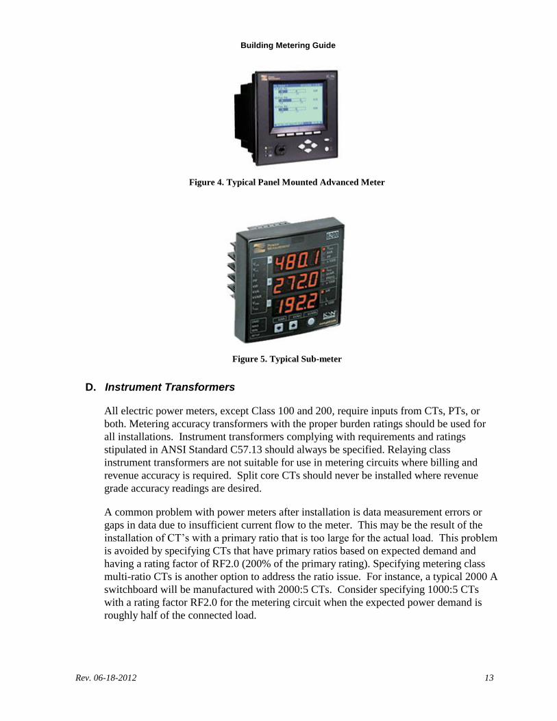
Figure 4. Typical Panel Mounted Advanced Meter
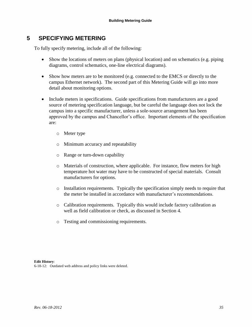
Figure 5. Typical Sub-meter
D. Instrument Transformers
All electric power meters, except Class 100 and 200, require inputs from CTs, PTs, or
both. Metering accuracy transformers with the proper burden ratings should be used for
all installations. Instrument transformers complying with requirements and ratings
stipulated in ANSI Standard C57.13 should always be specified. Relaying class
instrument transformers are not suitable for use in metering circuits where billing and
revenue accuracy is required. Split core CTs should never be installed where revenue
grade accuracy readings are desired.
A common problem with power meters after installation is data measurement errors or
gaps in data due to insufficient current flow to the meter. This may be the result of the
installation of CT’s with a primary ratio that is too large for the actual load. This problem
is avoided by specifying CTs that have primary ratios based on expected demand and
having a rating factor of RF2.0 (200% of the primary rating). Specifying metering class
multi-ratio CTs is another option to address the ratio issue. For instance, a typical 2000 A
switchboard will be manufactured with 2000:5 CTs. Consider specifying 1000:5 CTs
with a rating factor RF2.0 for the metering circuit when the expected power demand is
roughly half of the connected load.

Building Metering Guide
Rev. 06-18-2012 14
All metering devices require the installation of voltage and current circuit disconnecting
devices. These circuits should always include a properly rated (circuit voltage and
interrupting rating) fused disconnect with rejection type fuses and a CT shorting terminal
block with safety ground.
Figure 6. Typical Wattmeter Three-line Diagram with Instrument Transformers
3.3 Natural Gas
A. Meter Types
There are numerous common types of meters that may be used to measure natural gas –
diaphragm, rotary, turbine, and thermal gas mass flow.
Diaphragm meters are positive-displacement devices that have fixed-volume measurement
compartments formed by a two-sided convoluted diaphragm. A small pressure drop across the
meter causes it to cycle so these compartments alternately fill with gas at the inlet, and then
empty at the outlet. By counting the number of cycles, the meter provides a measure of gas
volume.

Building Metering Guide
Rev. 06-18-2012 15
Figure 7. Diaphragm Meter
Figure 8. Rotary Meter
Rotary meters are also positive-displacement measurement devices. In this case, a pair of
impellers form the fixed-volume compartments. When downstream demand initiates the flow of
gas, the impellers rotate to receive a fixed volume of gas at the inlet and then discharge it at the
outlet.
In place of fixed-volume compartments, a turbine meter has a rotor in the gas stream. As gas
flows through the meter, the rotor turns at a speed that is proportional to the rate of gas. This
type of meter is termed an inferential meter.
Figure 9. Turbine Meter

Building Metering Guide
Rev. 06-18-2012 16
Figure 10. Thermal Mass Meter
Natural gas thermal mass flow meters utilize a thermal sensing principle for direct mass
measurement of the gas. These meters can be specified as insertion type or in-line type. The
thermal mass flow sensor consists of two RTDs. The sensor elements are constructed of a
reference grade platinum wire wound around mandrels usually inserted into stainless steel or
Hastelloy tubes. The reference RTD measures the gas temperature. The instrument electronics
heats the mass flow sensor to a constant temperature differential above the gas temperature and
measures the cooling effect of the gas flow. The electrical power required to maintain a constant
temperature differential is directly proportional to the gas flow rate.
Deciding which type of meter is the best choice for a particular application depends upon the
following:
the pressure of the gas being measured
the maximum flow rate to be measured
the minimum flow rate to be measured
the cost of the meter
These issues are summarized in Table 3.

Building Metering Guide
Rev. 06-18-2012 17
Table 3. Domestic Water Flow Meter Comparison
Meter Type Maximum
Gas Pressure
psig
Maximum
(Minimum)
Capacity
scfh
Typical
Accuracy/
Rangeability
Advantages Disadvantages
Diaphragm 100 5,000
(no minimum)
±1% 100:1
Inexpensive
Good at measuring low flow rates
Mechanical components can get fouled and fail
Temperarature correction recommended
Rotary 285 16,000
(1,000 scfh minimum)
±1% 30:1 to 120:1
Good for commercial and industrial gas flow measurment
Mechanical components can get fouled and fail
Turbine 300 150,000
(50,000 scfh minimum)
±1%of reading
Great for large gas flow rates such as central heating plants
Low pressure drop
Expensive
Not good for measuring low flow rates
Thermal Gas Mass flow
300 384,000
(no minimum)
±1%+ 0.2% of full scale
Easy to install Straight pipe critical for accuracy and stability
B. Adjustment for Pressure and Temperature
Gas meters perform measurements at line conditions of pressure and temperature. This
measurement is known as the uncorrected volume. With many meters, it is necessary to convert
uncorrected volume to the equivalent volume at standard conditions (corrected volume). At line
pressures above the reference pressure (typically 14.73 psia), the corrected volume will be
greater than the uncorrected volume. The effect of pressure can be calculated as:
ref
ga tm
ACF
ref
aACFSCF
P
PPV
P
PVV
)(
where VSCF is gas volume in “standard” cubic feet, VACF is the actual volume, Pa is absolute gas
pressure, Pref is the reference gas pressure, Patm is atmospheric pressure, Pg is the gas gauge
pressure (pressure relative to atmospheric pressure).
When actual flowing temperatures are above the reference temperature (60ºF), corrected volume
will be less than the uncorrected volume. Conversely, at temperatures below 60ºF, corrected
volume will be greater than uncorrected volume. The effect of temperature can be calculated as:
)460(
)460(
g
ref
ACFSCFT
TVV
where Tref is the reference temperature and Tg is the actual gas temperature.

Building Metering Guide
Rev. 06-18-2012 18
In actual practice, some type of correcting device is normally used with a meter to automatically
convert to standard cubic feet. For diaphragm, rotary and turbine meters in an application where
line pressure is stable, the meter can be supplied with an index that corrects for a constant
pressure. Diaphragm and rotary meters can also be supplied with an integral continuous
mechanical temperature-compensating device for temperature correction. For turbine meters and
larger diaphragm meters, a correcting instrument is typically used.
3.4 Hot Water and Chilled Water
A. BTU Calculation
Metering building hot and chilled water energy usage requires the measurement of three
variables:
Entering water temperature (TE, ºF)
Leaving water temperature (TL, ºF)
Flow rate (GPM)
From these, energy usage, Q, in Btu/hr can be calculated as
)(**500 EL TTGPM
hmQ
This equation has several sources of error:
The equation assumes water is an incompressible fluid. This is a good assumption for
the pressures and temperatures commonly found in building hydronic systems.
The conversion “constant” 500 assumes a density and specific heat based on 68ºF water.
The value is reasonably accurate for chilled water but a few percent off for hot water.
This may or may not be significant in energy calculations depending on how the energy
data are used. If metering is for utility cost charge back, a more accurate calculation of
this constant is probably warranted and can be interpolated from the following table as a
function of average fluid temperature:
Table 4. Water Properties as a Function of Temperature
Property of
water
Units Symbol Temperature
40 60 80 100 200
Specific heat Btu/lbm- F c 1.006 1.001 0.999 0.999 1.006
Density lbm /ft3 62.42 62.36 62.21 61.99 60.12
Conversion
Constant
Btu-
min/gal-°F-
hr
C 503.4 500.7 498.6 496.7 485.1
Flow measurement can be quite inaccurate depending on the type of meter, calibration,
and how it is installed. Meter types are discussed in detail below.

Building Metering Guide
Rev. 06-18-2012 19
Temperature measurement accuracy also varies by sensor type and calibration. For non-
revenue metering of hot water, relatively inexpensive sensors can be used since the
temperature difference between entering and leaving water is generally large (>20ºF).
For chilled water applications, sensor accuracy relative to each other becomes significant
since the temperature differences can be small (<10ºF). For instance, if one sensor reads
1ºF high while the other is 1ºF low, the energy calculation can be on the order of 20%
off. Temperature sensor types are also discussed in more detail below.
B. BTU Meters
The BTU calculation above can be performed by the energy management & control system
(EMCS) from flow and temperature sensors or it can be done by a device called a “BTU meter.”
The BTU meter generally is configured to send calculated BTU data, optionally along with
individual temperature and flow measurement data, to the EMCS or other data collection system
for monitoring. It may also have a display for manual reading of internally stored energy usage
data. The main advantage of the BTU meter is that temperature sensors are factory matched to
minimize temperature difference calculation error. However, they generally cost more than
using individual sensors connected to the EMCS. Nevertheless, BTU meters are recommended
due to their improved temperature measurement accuracy and stability and ease of data
collection, particularly if energy is being metered for revenue purposes (allocating costs of
chilled or hot water usage per building).
Figure 11 shows a typical BTU meter. With this style, which is used for larger piping, the flow
meter and temperature sensors are all field mounted; with some smaller BTU meters, the flow
meter and one temperature sensor are built into the main meter housing. The temperature
sensors are provided with BTU meter so that they can be factory matched and calibrated for
improved accuracy. The flow meter can be any type depending on the desired accuracy – see
flow meter discussion below. The output of the Btu meter can be a pulse or analog output
connected to an EMCS or other data collection system. Modern BTU meters also include the
ability to directly connect to common control networks such as BACnet/MSTP, Modbus/EIA-
485, LonWorks, and various proprietary networks. This allows, at low cost, not only the BTU
data but also the flow and temperature data to be monitored by the EMCS.

Building Metering Guide
Rev. 06-18-2012 20
Figure 11: BTU Meter
C. Flow Meters
The most common flow meters used for chilled and hot water metering applications are:
Turbine (Figure 12)
Full-bore magnetic (Figure 13)
Single point magnetic (Figure 14)
Vortex shedding (Figure 15)
Transit time ultrasonic (Figure 16)
This Guide does not include a description of how each meter works; the reader is referred to
manufacturer’s websites for this information. Another resource is ASHRAE’s Fundamentals of
HVAC Controls self-directed learning textbook.

Building Metering Guide
Rev. 06-18-2012 21
Figure 12. Dual Turbine Meter
Figure 13. Full Bore Magnetic Meter

Building Metering Guide
Rev. 06-18-2012 22
Figure 14. Insertion Magnetic Meter

Building Metering Guide
Rev. 06-18-2012 23
Figure 15. Vortex Shedding Meter
Figure 16. Transit Time Ultrasonic Meter
Table 5 compares the features, advantages and disadvantages of these meters, with application
issues summarized below:
The turbine meter is perhaps the most common for this application because of its low
cost, but it is prone to clogging on open systems such as condenser water systems.
Because of the moving parts, routine maintenance is required.
Full bore magnetic flow meters are the best from an accuracy (very accurate even at very
low flow rates) and operational standpoint (lowest maintenance costs, longest lasting),
but they are expensive. Until recently they were extremely expensive because most
manufacturers designed the meters for the more demanding industrial market, but
commercial quality meters are now available at much lower cost. Because the full bore
meter senses the entire water flow (not just a single point), they are much less sensitive
to installation problems; as long as turbulence does not cause reversing eddy currents
within the flow tube the meter will be accurate.
Single point magnetic meters are often used for large piping when the cost of full bore
meters becomes prohibitive, but because they measure flow only at a single point in the
pipe, they are much less accurate than full bore meters.
Vortex shedding meters were more common before magnetic meters came down in
price. They are now more commonly used on gas and steam flow. A significant
limitation is that they are not very accurate at low flow.
Ultrasonic meters are non-invasive, i.e. they do not require any openings into the pipe,
and were initially used for ad hoc flow measurements such as for test and balance.
Installation details are critical. Manufacturers provide jigs and assemblies to ensure the
sensors are accurately installed, but they are still prone to inaccuracies from installation
error. Because they are non-invasive, ultrasonic meters are particularly applicable to
retrofit applications.
For metering chilled and hot water flows at buildings, particularly for revenue purposes, the full
bore magnetic flow meter is strongly recommended. The pipe sizes are generally small enough
at building connections that these meters are affordable. If budget constraints are such that they

Building Metering Guide
Rev. 06-18-2012 24
are cost prohibitive, dual turbine meters are recommended. They are reasonably accurate if well
maintained but they are relatively inexpensive. Full bore magnetic flow meters are also strongly
recommended for metering total central plant output of variable flow chilled water and heating
hot water systems.
Table 5. HW & CHW Flow Meter Comparison
Type Configuratio
n
Typical
Accuracy/
Minimum
Flow
Advantages Disadvantages
Turbine (single for small pipes, dual for pipes 2.5” and larger)
Insertion ±2%
0.5 fps
Usually least expensive
Insertion style allows easy retrofit (via hot tap) and removal for cleaning, replacement
Can be fouled by contaminants in water; not recommended for open circuit systems
Moving parts result in lower operating life, possibly degrading accuracy
Requires correct installation depth to be accurate
Sensitive to installation details – long straight inlet and outlet runs required
Full-bore magnetic Flow tube ±0.5%
0.05 fps
Most accurate meter
Lowest minimum flow rate
Least sensitive to installation problems and requires least amount of straight piping runs at inlet and discharge
Very little maintenance required; no moving parts
Long life with little calibration required
Most expensive meter, and especially expensive for large pipes (>12”)
Cannot be removed without shutting off system or providing an expensive bypass
Single point magnetic
Insertion ±1%
0.2 fps
Insertion style allows easy retrofit (via hot tap) and removal for cleaning, replacement
Very little maintenance required; no moving parts
Long life with little calibration required
Relatively expensive for small pipe sizes
Requires correct installation depth to be accurate
Sensitive to installation details – long straight inlet and outlet runs required
Vortex shedding Insertion ±2%
1 fps
Insertion style allows easy retrofit (via hot tap) and removal for cleaning, replacement
Not accurate at low flows
Can be fouled by contaminants in water;
Requires correct installation depth to be accurate
Sensitive to installation details – long straight inlet and outlet runs required

Building Metering Guide
Rev. 06-18-2012 25
Type Configuratio
n
Typical
Accuracy/
Minimum
Flow
Advantages Disadvantages
Transit time ultrasonic
External ±0.5%
1 fps
External mount allows easy retrofit and replacement
No moving parts and no parts exposed to fluid so maintenance costs are low
Relatively expensive for small pipe sizes
Not accurate at low flows or quick rate of change
Requires correct configuration to be accurate – sensitive to configuration details such as pipe dimensions and wall thickness
Sensitive to installation details – long straight inlet and outlet runs and precise mounting required
D. Temperature Sensors
The most common temperature sensing devices used in hydronic applications are:
Thermistors
Resistance Temperature Detectors (RTDs)
Integrated circuit (solid-state) temperature sensors
These all use materials whose resistance or impedance changes with temperature.
Thermistors are generally the least expensive and are fairly accurate (±0.4ºF for standard
thermistors, ±0.2ºF for extra precision thermistors). Historically they had problems staying in
calibration but this is not a problem with modern thermistors which drift less than about 0.04°F
over a five-year period. Thermistors have sufficient resistance that they may be connected to the
EMCS with only a two-wire connection; a transmitter is not required. Their temperature range
is very broad so a single thermistor sensor can be used for virtually all HVAC applications;
specific ranges do not have to be specified. Their signal is non-linear with respect to
temperature changes so signal conditioning is required, but this capability is standard for most
modern EMCS.
RTDs were once the most common temperature sensor in HVAC applications, but they recently
have been mostly displaced by less expensive thermistors. RTDs have low resistance so
transmitters are required and, unlike thermistors, they must be ordered for the specific
temperature range required by the application. Accuracies of RTDs vary widely from ±0.02°F to
±1.0°F depending on the material (platinum is most common) and construction.
Integrated circuit temperature sensors are not commonly used in HVAC applications except with
BTU meters. They are not very accurate (~±1.0°F) but they are extremely repeatable and linear.
They also do not require calibration. Hence they are excellent for differential temperature
measurement once the two sensors are matched and calibrated at the factory. Differential
temperature measurement accuracy is typically about ±0.15 F.
Differential temperature accuracy and sensor recommendations for metering purposes are:

Building Metering Guide
Rev. 06-18-2012 26
Hot Water Systems. Differential temperature accuracy: ±0.5ºF. Two extra precision
thermistors (±0.2ºF each) can meet this requirement, as can high accuracy RTDs with at
least ±0.25ºF accuracy, and matched integrated circuit sensors supplied with a BTU
meter.
Chilled Water Systems. Differential temperature accuracy: ±0.15ºF. Thermistors will
not be able to meet this accuracy requirement. Ultra-high accuracy RTDs or matched
integrated circuit sensors supplied with a BTU meter must be used.
The accuracy and long term stability of the BTU meter integrated circuit sensors is one of their
main advantages and why BTU meters are recommended for chilled and hot water flow
metering.
3.5 Steam
Steam usage can be metered in two ways:
Measuring steam vapor flow and converting to mass flow (lbs/hr) by adjusting for
density variations based on steam temperature or pressure (if steam is assumed to be
saturated) or based on temperature and pressure (if steam is superheated)
Measuring steam condensate flow and converting to mass flow (lbs/hr) by adjusting for
density variations based on fluid temperature
Historically, the latter approach was most popular because measuring liquid flow was much less
expensive and it is accurate over a very wide flow range. Utility grade diaphragm meters were
most commonly used (see Figure 7) particularly for building sub-metering applications, but
turbine meters (see Figure 9) are another option. However, condensate flow does not include
processes for which no condensate is returned, such as steam used for humidification and some
sterilizers. With the advent of more accurate gas flow measurement devices, direct
measurement of steam is becoming the preferred metering approach and the approach
recommended for CSU campuses.
The most common steam volumetric flow measuring device is the vortex shedding meter (see
Figure 15). It is accurate across a fairly wide flow range (at least 25::1 but as high as 150::1),
but as with all meters its accuracy drops off at very low flow rates. If the range is expected to
vary widely and accuracy is required at low flow rates, consider splitting the steam service into
two or more (e.g. one service for year-round low flow steam usage and another for high flow
winter heating and humidification loads) each with its own meter sized for the expected flow
rate and range.
Steam vapor volumetric flow rate can be converted to mass flow rate using the following
equation:
VG

Building Metering Guide
Rev. 06-18-2012 27
where G is the mass flow rate (lbs/hr), V is the volumetric flow rate (ft3/hr) as measured by the
flow meter, and is the specific volume (ft3/lb). To determine the specific volume for
saturated steam, steam temperature or pressure must be measured from which specific volume
can be determined from a look-up table (Table 6) or equations approximating the table. For
superheated steam, both temperature and pressure must be measured from which specific
volume can be approximated by perfect gas laws or determined more accurately with empirical
correlations with temperature and pressure. Typically steam is not superheated by the time it
reaches the meter from the steam boilers so these more complex calculations are not required.

Building Metering Guide
Rev. 06-18-2012 28
Table 6. Specific Volume for Saturated Steam
Temperature
, °F
Pressure Specific
Volume,
ft3/lb
Absolute,
psia
Gauge,
psig
212 14.7 0.0 26.802
220 17.2 2.5 23.133
230 20.8 6.1 19.371
240 25.0 10.3 16.314
250 29.8 15.1 13.815
260 35.4 20.8 11.759
270 41.9 27.2 10.058
280 49.2 34.5 8.6431
290 57.6 42.9 7.4600
300 67.0 52.3 6.4658
310 77.7 63.0 5.6263
320 89.7 75.0 4.9142
330 103.1 88.4 4.3075
340 118.0 103.3 3.7884
350 134.6 119.9 3.3425
Many meters are available that make the volumetric to mass flow rate conversion using a built-
in temperature or pressure sensor and conversion logic within the meter transmitter so that
external conversion to mass flow rate is not required. Figure 17 is an example or a vortex
shedding meter with this capability.
Figure 17. Vortex Shedding Meter with Integral Mass Flow Conversion
3.6 Domestic Water
A. Meter Types
Water meters can be classified into two basic types: positive displacement and velocity. Each of
these meter types has variations, leading to the perception that there are several different kinds.
Meters that feature both positive displacement and velocity are known as compound meters. The

Building Metering Guide
Rev. 06-18-2012 29
unit of measurement is typically in gallons or cubic feet. Water meters specified should meet
performance and accuracy requirements listed in the American Water Works Association
(AWWA) applicable standards.
Positive Displacement Meters
In this type of meter, a known volume of liquid in a tiny compartment moves with the
flow of water. Positive displacement flow meters operate by repeatedly filling and
emptying these compartments. The flow rate is calculated based on the number of times
these compartments are filled and emptied. The movement of a disc or piston drives an
arrangement of gears that registers and records the volume of liquid exiting the meter.
There are two types of positive displacement meters: nutating disc and piston.
Nutating disc meters have a round disc that is located inside a cylindrical chamber. The
disc is mounted on a spindle. The disk nutates, or wobbles, as it passes a known volume
of liquid through the cylindrical chamber. The rotating motion of the disk is then
transmitted to the register that records the volume of water that went through the meter.
(See Figure 1 below.)
Piston meters have a piston that oscillates back and forth as water flows through the
meter. A known volume of water is measured for each rotation, and the motion is
transmitted to a register through an arrangement of magnetic drive and gear assembly.
Positive displacement meters are sensitive to low flow rates and have high accuracy over
a wide range of flow rates. Positive displacement meters are used for smaller flow
applications. They are available in sizes from 5/8” to two inches.
Velocity Meters
Velocity meters operate on the principle that water passing through a known cross-
sectional area with a measured velocity can be equated into a volume of flow. Velocity
meters are good for high flow applications.
Velocity meters come in different types, including venturi, orifice, turbine, ultrasonic,
and magnetic meters.
Venturi meters (Figure 18) have a section that has a smaller diameter than the pipe on the
upstream side. Based on a principle of hydraulics, as water flows through the pipe, its
velocity is increased as it flows through a reduced cross-sectional area. Difference in
pressure before water enters the smaller diameter section and at the smaller diameter
“throat” is measured. The change in pressure is proportional to the square of velocity.
Flow rate can be determined by measuring the difference in pressure. Venturi meters are
suitable for large pipelines and do not require much maintenance.

Building Metering Guide
Rev. 06-18-2012 30
Figure 18. Venturi Flow Meter
Orifice meters (Figure 19) work on the same principle as venturi meters, except that,
instead of the decreasing cross-sectional area, there is a circular disk with a concentric
hole. Flow rate is calculated similarly to the venturi meter by measuring the difference in
pressures. Pressure drop is very high through these meters and consequently they are
seldom used in modern applications.
Figure 19. Orifice Plate Flow Meter
Turbine meters have a rotating element that turns with the flow of water. The number of
rotor revolutions measures volume of water. See Figure 9.
Magnetic meters have an insulated section through which water flows. The flow of water
induces an electrical current that is proportional to the velocity and hence the flow rate.
See Figure 13.

Building Metering Guide
Rev. 06-18-2012 31
Compound Meters
In some cases, it is necessary to have a combination meter—both a positive displacement
meter and velocity meter installed together—to be able to measure extremely high flow
rate applications. Low flows are measured through positive displacement while high
flows are measured by velocity. A valve arrangement directs flows into each part of the
meter.
B. Selecting a Meter
Meters are selected using several factors: flow range, size of pipe, pressure loss and safety
considerations, such as fire service regulations. The most common meters used in domestic
water applications are positive displacement and turbine flow meters.
For sizes of one inch and smaller and low flow rates, positive displacement types of meters are
common.
For flows up to 160 gpm, positive displacement meters in sizes of 1”, 1-1/2”, or two inches are
commonly used. In sizes of 2-3 inches, either, displacement or turbine types of meters can be
used. In the 3-4 inch size range, the meter type depends on the average flow rate. If the flow rate
is between five and 35 percent of maximum flow rate, the positive displacement type is better. If
the flow rates are going to be 10 to 15 percent of the maximum capacity, a turbine type should
be used. If close accuracy at low flows is important, but large flows also have to be measured, a
compound meter is best.
Venturi meters can be considered as an option for a large range of flows such as metering a main
if you need a meter that will not interfere with the flow if the meter fails. Magnetic meters offer
high accuracy with no head loss but are the most expensive option for metering water.
C. Meter Installation
Meters are installed either in outdoor meter pits (also known as meter wells) or inside the
building served. General guidelines for installing meters are:
In outdoor meter pits, the face of the meter should be between 18 and 24 inches from the
ground surface or top of the meter pit lid.
Meter pits or wells should have six to 12 inches of gravel at the bottom to help with
drainage.
If at all possible, the meter pit or well should not be located in an area prone to flooding.
The meter setting should have a shut-off valve on both sides of the meter
If possible, the meter should be installed in a horizontal position.

Building Metering Guide
Rev. 06-18-2012 32
The meter should be easily accessible for service, inspection, and reading
Protect the meter from freezing, where applicable
3.7 Sewage
The most accurate sewage flow meter is a full-bore magnetic flow meter (Figure 13) in part
because it can measure flow in a partially filled waste line. Most other sensors (e.g. single point
magnetic, turbine, and ultrasonic meters) cannot be used to measure flow in partially filled
pipes. Unfortunately, full-bore magnetic flow meters are extremely expensive for the size
required for most waste lines.
A less expensive option is a velocity meter (e.g. ultrasonic, single point electromagnetic)
combined with a level meter (e.g. radar) or depth meter (e.g. pressure transducer) to estimate
flow area. Accuracy is typically no better than ±5%.
Another option commonly used prior to the affordability of velocity meters but less popular
today is the weir meter. It consists of an obstruction (see Figure 20) across the open channel
with a specially shaped opening or notch. The obstruction results in an increase in the water
level upstream of the structure. The flow rate can be calculated from this depth (measured with
an ultrasonic level sensor or pressure transducer), basic flow equations, and a field calibrated
flow coefficient. One obvious problem with weir meters is that flow is restricted possibly
causing a sewage backup.
Figure 20. Weir Meters
Because of the expense and potential problems, measuring sewage flow should only be
considered when water use for irrigation or evaporative processes (e.g. cooling towers,
evaporative condensers, direct/indirect evaporative cooling) are large and the local utility
provides a financial credit for the reduced sewer burden. Even in these cases, it is usually more
cost effective to sub-meter the water flow to these applications and deducting these flows from
overall water usage.

Building Metering Guide
Rev. 06-18-2012 33
4 COMMISSIONING AND CALIBRATION
4.1 Definitions
Commissioning and calibration of metering devices are the processes that contribute to the
proper installation and provision of adjustments necessary to generate accurate meter data. The
accuracy and reliability of the data obtained from meters largely depends on whether they are
properly installed and calibrated. Installation details must strictly follow the meter
manufacturer’s instructions. Once a meter is properly installed, a process must be conducted to
confirm accuracy and calibration.
Accuracy is the ability of a measurement to match the actual value being measured. Calibration
is the act of checking or adjusting the accuracy of meter by comparison it with a known
standard. The known standard in the case of most meters can be a portable meter of greater
accuracy with calibration traceable to the National Institute of Standards and Technology
(NIST). All revenue grade meters should have a calibration certificate indicating measurements
traceable to the NIST or equivalent institution. Meter manufacturers and suppliers must produce
the criteria for installed accuracy validation. Documentation affirming that the meter was
properly installed and providing accurate data should be specified to be a part of the
commissioning process.
4.2 Installation
Proper installation must be verified in detail by a commissioning process containing checklists
of all items and processes necessary to ascertain compliance to the installation criteria provided
by the meter manufacturer. Different types of meters have very specific installation requirements
that are necessary for proper function. The meter manufacturer installation procedures and
recommendations should be followed in detail. Meters should be installed by factory qualified
contractors under the supervision of the project commissioning agent, the project inspector, the
project manager and the engineer of record.
4.3 Practical Accuracy Validation Process
Since NIST traceable accuracy validation my be impractical , expensive, or unnecessary for
certain applications, a more practical approach should be implemented as discussed below
followed by a formal approach for cases that require a formal traceable calibration process.
It is at times more practical to require that meters be factory calibrated rather than field
calibrated since the necessary instrumentation and test rigs are readily available in the factory.
This is particularly true of flow meters, since field calibration is often impractical if not
impossible, due to lack of a good location to mount a temporary meter (it is hard enough finding
a good location for the permanent meter) and because finding a sufficiently accurate temporary
meter may not be practical. Still, a check must be made to ensure that the meter and transmitter
were properly configured. For instance, a flow meter can be checked by causing the entire flow
to go through a device with a flow measurement capability (however accurate) or with a known

Building Metering Guide
Rev. 06-18-2012 34
flow and pressure drop relationship (e.g. a chiller). This test will allow the meter to be checked
for the right order of magnitude reading to ensure proper configuration, but it cannot be used for
actual calibration; the factory calibration must be relied upon.
It is ultimately the responsibility of the project team to assure that the data produced by a meter
is sufficiently reliable for the given application. For applications requiring a very high degree
assured accuracy a more formal process should be followed as discussed below.
4.4 Formal Calibration and Validation Process
Formally, the definition of calibration traceability that has achieved global acceptance in the
metrology community is contained in the International Vocabulary of Basic and General Terms
in Metrology (VIM; 1993):
"…The property of the result of a measurement or the value of a standard whereby it can be
related to stated references, usually national or international standards, through an unbroken
chain of comparisons, all having stated uncertainties."
It is important to note that traceability is the property of the result of a measurement, not of an
instrument or calibration report or laboratory. It is not achieved by following any one particular
procedure or using special equipment. Merely having an instrument calibrated, even by NIST, is
not enough to make the measurement result obtained from that instrument traceable to
realizations of the appropriate SI unit or other stated references. The measurement system by
which values are transferred must be clearly understood and under control. In other words,
traceable measurements or meter data must follow a traceable calibration protocol involving
proper instruments and certified calibration professionals.
Therefore a thorough review of the installation process and requirements for each meter needs to
be conducted. This process must address proper installation, calibration verification and
traceability to a known established standard. Usually, manufacturer installation manuals furnish
specific information on the proper installation of meters and related devices.
Test equipment used for testing and calibration of field devices shall be at least twice as accurate
as respective field device. For example if field device is ±0.5% accurate, test equipment shall be
±0.25% accurate over same range.
Building Metering Guide
Rev. 06-18-2012 35
5 SPECIFYING METERING
To fully specify metering, include all of the following:
Show the locations of meters on plans (physical location) and on schematics (e.g. piping
diagrams, control schematics, one-line electrical diagrams).
Show how meters are to be monitored (e.g. connected to the EMCS or directly to the
campus Ethernet network). The second part of this Metering Guide will go into more
detail about monitoring options.
Include meters in specifications. Guide specifications from manufacturers are a good
source of metering specification language, but be careful the language does not lock the
campus into a specific manufacturer, unless a sole-source arrangement has been
approved by the campus and Chancellor’s office. Important elements of the specification
are:
o Meter type
o Minimum accuracy and repeatability
o Range or turn-down capability
o Materials of construction, where applicable. For instance, flow meters for high
temperature hot water may have to be constructed of special materials. Consult
manufacturers for options.
o Installation requirements. Typically the specification simply needs to require that
the meter be installed in accordance with manufacturer’s recommendations.
o Calibration requirements. Typically this would include factory calibration as
well as field calibration or check, as discussed in Section 4.
o Testing and commissioning requirements.
Edit History:
6-18-12: Outdated web address and policy links were deleted.