Embed Size (px)
Citation preview
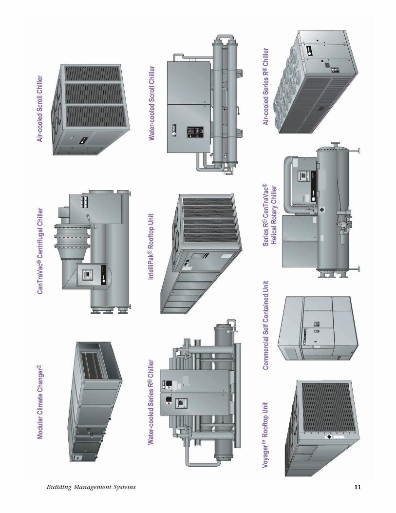
Building Management Systems
The Trane CompanyWorldwide Applied Systems Group3600 Pammel Creek RoadLa Crosse, WI 54601-7599
www.trane.com© American Standard Inc. 1999
BAS-DS-1Supersedes BAS-DS-1-796
File No. PL-ES-BAS-000-DS-1-0499
Printed on recycled paper.
The Trane Company has a policy ofcontinuous product improvement andreserves the right to change designand specification without notice.
© American Standard Inc. 1999. All rights reserved.
Cover illustration: Frank Miller Studios, Inc.
Published by the Trane Building Automation Systems, St. Paul, Minnesota. Printed in the USA.
Integrated Comfort, Tracer 100i, and Voyager are trademarks of The Trane Company. CenTraVac, Series RCenTraVac, IntelliPak, Climate Changer, Series R, 3-D, Tracer, Tracer Summit, Tracker, Trane, VariTrac, andVariTrane are registered trademarks of The Trane Company.
The following are trademarks or registered trademarks of their respective companies: ARCNET fromDatapoint Corporation, AutoCAD from Autodesk, Inc., BACnet from ASHRAE, Pentium from IntelCorporation, 3Com/U.S. Robotics Sportster from 3Com, and Windows and Internet Explorer from MicrosoftCorporation.
ContentsTrane Building Management Systems
Standalone Building Control .......................................... 2Networked Building Control ......................................... 4Chiller Plant (Subsystem) Management ........................ 6Simple Building Control ................................................. 8
ICS ArchitectureOperator Interface .......................................................... 12Building Control ............................................................. 12Unit Control .................................................................... 12
Operator InterfaceTracer Summit PC Workstation ...................................... 13Building Management Network ..................................... 16
Building ControlTracer Summit Building Control Unit ............................ 17Tracer 100 Series Systems: Tracer L, CPM, and 100i ...... 18Tracker and VariTrac Zoning System ............................. 20Simple Zoning Control ................................................... 21
General-Purpose Unit ControlThermostat Control Module .......................................... 23Programmable Control Module ..................................... 24Universal Programmable Control Module ..................... 24
Application-Specific Unit ControlTerminal Unit Controller ................................................ 26Lighting Control Panel ................................................... 27DDC Chiller Sequencer .................................................. 28
Factory-Mounted Unit ControlChillers ............................................................................ 29VariTrane VAV Terminal Units ......................................... 29Commercial Self Contained Units ................................. 29IntelliPak Rooftop Units ................................................. 30Voyager Rooftop Units ................................................... 30Air Handlers .................................................................... 30Terminal Unit Controllers .............................................. 30VariTrac Changeover-Bypass Zoning System ................. 30VAV Command Unit ....................................................... 30
Trane SensorsSensors ............................................................................ 31
Building Management Systems 1
Trane Building Management SystemsThe Trane Company’s line ofbuilding management systemsincludes a product for everycontrol need, from a remedy for aproblem area in an existingbuilding to a comprehensivesystem for a major complex orcampus. Trane buildingmanagement system capabilitiesand features include:
• Scheduling for weekdays andholidays
• After-hours usage tracking
• Management reports and logs
• Dynamic and interactive colorgraphics
• Direct digital control and customprogramming routines
• Comfort monitoring by zone
• Energy-saving software includingchiller plant control, demandlimiting, optimal start/stop, andnight setback
• Operator interface that is easy tolearn and use
• Architecturally-compatible,ergonomic design
Trane is unique in its ability to offertotal Integrated Comfort systems,HVAC, controls, and buildingmanagement from a single source.These systems constitute avigorous response to today’sdemands from regulatory agencies,building designers, contractors,owners, and occupants.
Pages two through nine in thiscatalog illustrate four typical Tranebuilding management systemapplications. They demonstrate theversatility and integrationcapabilities of the various productsin this catalog. Each Trane buildingmanagement installation isdesigned specifically for the facilityit manages and may be configureddifferently than the examplesshown.
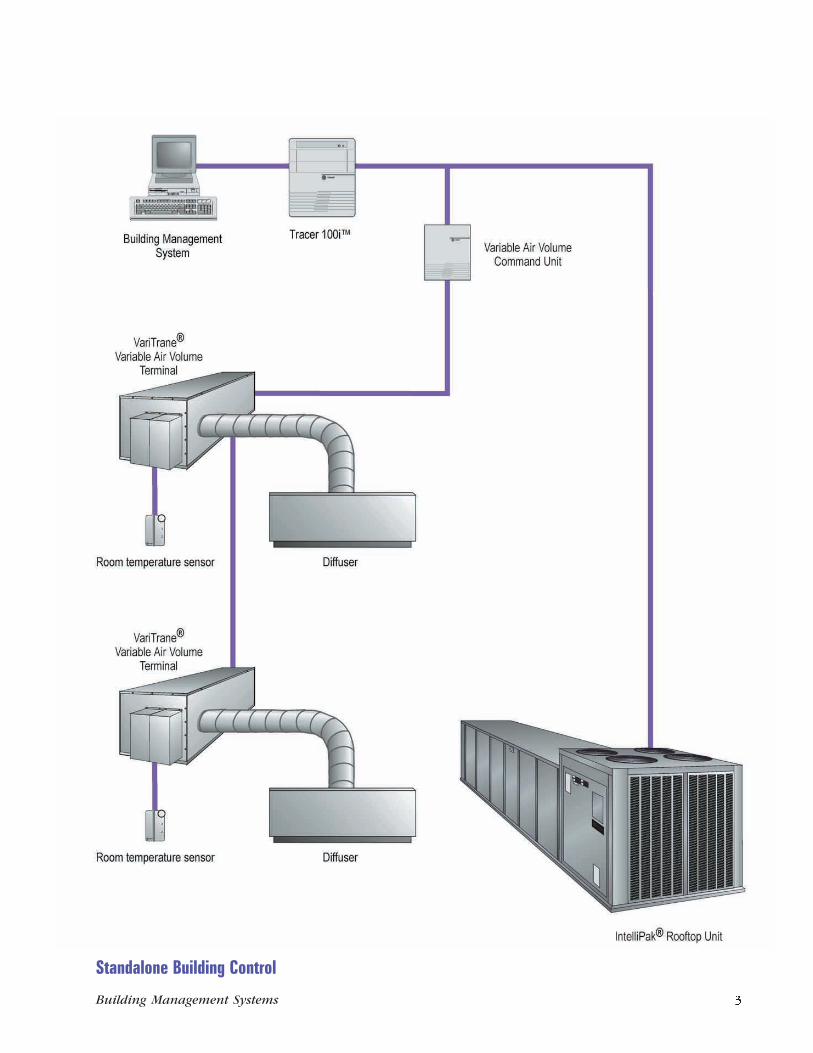
Standalone Building ControlSystems
• Applied commercial
• Unitary
Building Size
• Mid-size to large
Features
• Time of day schedulingincluding optimum start/stopand night purge
• Demand limiting
• Timed override
• Reports and trends
• Remote communications
• Custom programming routines
• Chiller sequencing
• Year 2000 compliant
• Manufactured in an ISO 9001certified facility
Benefits
• Comprehensive set of reports totrack and analyze data
• Reduced energy costs withstandard, tested energymanagement applications
• Flexibility to provide after-hourscomfort through timed override
• Quick identification of operatingproblems using equipmentdiagnostics
• Easy-to-use, dynamic colorgraphics (optional)
For more information about See page
IntelliPak Rooftop Unit .............................................................. 30
Room Temperature Sensor ......................................................... 31
Tracer 100i ................................................................................. 18
Variable Air Volume Command Unit .......................................... 30
VariTrane Variable Air Volume Terminal Unit ............................. 29
Trane SensorsControlling the comfort in abuilding space begins with Tranesensors. We designed our sensorsfor use with Trane Tracer systemsto provide the accuracy andrepeatability required by DDCcontrol. Trane sensors arecompatible with a variety of Tranebuilding level and unit levelcontrollers. In addition, thesensors are architecturallycompatible with each other andwith modern building interiors.
Sensor CapabilitiesTrane room temperature sensorsare available in several variations,and include options for setpointadjustment and override switches.Use Trane room humidity sensorsto control humidifiers anddehumidification equipment.Controlling building humidity is animportant element in maintainingindoor air quality. Trane also offersfield-applied sensors to measurepressure, temperature, andhumidity in air and waterapplications.
CO2 Sensor CapabilitiesCarbon dioxide is present in the airin variable amounts and can bemeasured in parts per million(PPM) by the Trane CarbonDioxide (CO2) Sensor. Elevatedconcentrations of carbon dioxidein a building zone can indicate aspace is occupied above designconditions, or that there is a
problem or deficiency with thebuilding’s ventilation system.
When connected to a Tracerbuilding management system andthe appropriate ventilationequipment, the Trane CO2 Sensorprovides building designers,operators, and owners a practicaland affordable means to respond toconcerns of indoor air quality andoccupant comfort.
Typical applications for the CO2Sensor include:
• Monitoring and recording CO2
levels in occupied buildingspaces
• Identifying underventilated
building zones
• Overriding outdoor air flow
beyond design ventilation rates ifCO2 exceeds an acceptable level
• Using CO2 measurement toidentify changes in occupancy
of a space
Hardware Description
The Trane CO2 Sensor can eitherbe wall-mounted or duct-mountedusing an optional duct enclosurekit.
For more information on the CO2 Sensor, referto Trane publication BAS-PD-8.
2 Building Management Systems Building Management Systems 31
IntelliPak Rooftop UnitsThe 20- to 130-ton IntelliPakRooftop is a self-contained heatingand cooling air handling unit. TheIntelliPak can be configured aseither constant volume or variableair volume system control. TheIntelliPak UCM is factory-installedon each unit, and can be connectedto a Tracer Summit BCU or a Tracer100 series controller via a TraneCommunication Interface (TCI).Each system provides control,monitoring, and diagnostics for therooftop unit.
For more information about IntelliPak Rooftops,refer to Trane publication RT-DS-8.
Voyager Rooftop UnitsThe 3- to 50-ton Voyager Rooftopunit is a self-contained heating andcooling air conditioner normallyinstalled on a building’s roof. Wedesigned the Voyager Rooftop tocompete in the price-competitivemarket of light commercialpackaged rooftops. The Voyagercan be factory-configured for eitherconstant volume or variable airvolume (27½- to 50-ton VoyagerCommercial only) system control.The Voyager Micro is applied on allTrane Voyager Rooftops and can beconnected to a Tracer Summit BCU,a Tracer 100 series controller or aTracker panel via a TCI. Eachsystem provides control,monitoring, and diagnostics for therooftop unit.
For more information about Voyager Rooftops,refer to Trane publications RT-DS-9, YC-D-7,WC-D-4, and TC-D-5.
Air HandlersTrane’s indoor, outdoor, andcustom air handlers are available
with complete turnkey factory-packaged controls systems.Universal PCMs, PCMs, sensors,actuators, and other controldevices (including starters andvariable frequency drives) arefactory-engineered, mounted,wired, and tested.
Six standard factory PCM programsare available. Custom programs canbe written and factory-downloadedto meet special buildingrequirements. Simple connectionsfor power, piping, and ductwork,and a basic startup sequence helpminimize labor and expediteconstruction cycles. Each airhandler performs fully standalone,or can be tied with a pair of wiresto a Trane Tracer buildingmanagement system.
For more information about air handlercontrol systems, refer to Trane publicationCLCH-S-24, CLCH-DS-7, CLCH-DS-9, andPCC-DS-1.
Terminal Unit ControllersThe Trane Terminal Unit Controller(TUC) is a microprocessor-based,direct digital controller used on thefollowing terminal products:
• Fan coils
• Water source heat pumps
• Unit ventilators
• Blower coil air handling units
The TUC is configurable from a listof predefined features including 2-pipe or 4-pipe valve control, faceand bypass damper control,compressor control, andeconomizer control. The TUC canbe applied as a field-installedcontroller to retrofit existing aircondition equipment, includinginstallation in non-Traneequipment. In addition, the TUC isavailable factory installed, wired
and tested in Trane air conditioningequipment.
For more information about Terminal UnitControllers, refer to page 26 of this catalog orTrane publication BAS-PD-7.
VariTrac Changeover-BypassZoning SystemThe VariTrac Central Control Panel(CCP) provides coordination,monitoring, and diagnostics for theVariTrac zone control system. TheCCP also communicates with theVariTrac zone dampers todetermine space heating andcooling requirements. The VariTracZoning System can communicatewith Tracer Summit, the Tracer 100series building controllers, and theTracker building control panel.
For more information about VariTrac CentralControl Panel, refer to Trane publicationsBAS-TS-73 and VAV-DS-12. Also, refer topage 20 in this catalog.
VAV Command UnitThe Tracer 100 series VAVCommand Unit system providescontrol, monitoring, anddiagnostics of Trane VAV terminalunits. Through the VAV CommandUnits, the Tracer 100 series panelcan maintain and monitorindividual zone comfortrequirements. The Tracer panelalso makes the comfort systemflexible to occupants’ cooling andheating requirements by groupingVAV terminal units togetherthrough software.
For more information about VAV CommandUnits, refer to Trane publication BAS-TS-64.
Standalone Building Control
30 Building Management Systems Building Management Systems 3
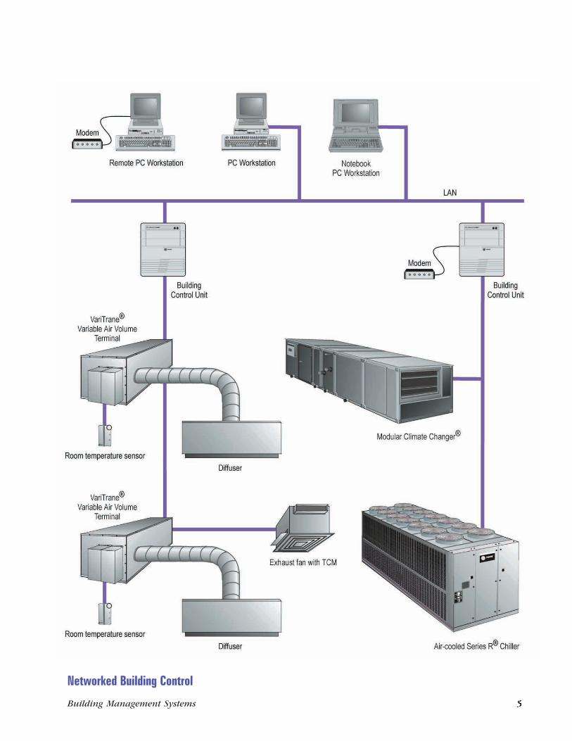
For more information about See page
Air-cooled Series R Chiller ......................................................... 29
Building Control Unit ................................................................. 17
Tracer Summit PC Workstation Software .................................. 13
Modular Climate Changer Air Handler ...................................... 30
Room Temperature Sensor ......................................................... 31
Networked Building ControlSystems
• Applied commercial
• Unitary
Building Size
• Mid-size to large
Features
• Chiller plant control
• High speed ARCNET or EthernetLAN communications betweenpanels
• Graphical user interface
• Remote communications
• Custom programming routines
• Reports and trends
• Time of day scheduling includingoptimum start/stop and nighteconomizing
• Area control to coordinate HVACequipment and lighting
• VAV air system control
• Interoperability with other non-Trane systems and subsystemsusing the BACnetcommunications protocol
• Year 2000 compliant
• Manufactured in an ISO 9001certified facility
Benefits
• Reduced operating costs throughenergy management strategies
• Flexibility to grow with buildingexpansion or remodeling
• Easy-to-learn, easy-to-usegraphical user interface
• Consistent, reliable operationwith standard, pre-engineeredand pre-tested applications
• Easier, faster troubleshootingwith in-depth data and diagnosticinformation
• Advance notice of systemproblems before they become anemergency
• Automatic printing or saving ofreports for analysis or regulatorypurposes
• Quick, at-a-glance graphicalviews of current building status
• Safety and peace of mind withmulti-level operator security
• Truly open communications toBACnet-compatible subsystemsor non-Trane equipment
Factory-Mounted Unit ControlTrane’s Integrated Comfort systems(ICS) concept incorporates thebenefits of factory-mounted, wired,and tested microprocessor controlson each piece of Trane equipmentdescribed in this section. TraneTracer building managementsystems link the HVAC equipmentinto truly integrated comfortsystems that address the criticalissues facing building owners,engineers, and contractors.
ChillersTrane chillers are available with acompressor type, refrigerant type,and capacity to meet nearly anyneed. These chillers are designedto provide a reliable source ofchilled water and are equally suitedfor comfort, industrial, or processapplications.
Unit controllers factory-mountedon Trane chillers provide access toinformation and functions withineach chiller. This access allows thebuilding management productsdescribed in this catalog tooptimize the operation of eachchiller individually and to optimizetheir performance within a chillerplant.
You can link any of the chillerslisted below to a Trane ICS toprovide system-level monitoring,diagnostics, and controlcapabilities, including sequencingchillers as well as controllingpumps and cooling towers:
• CenTraVac Centrifugal Chillers
• Series R CenTraVac HelicalRotary Chillers
• Air-cooled and water-cooledHelical Rotary Chillers
• Air-cooled and water-cooledScroll Chillers
• Absorption Chillers with UCP2,classic or Horizon controls
Refrigerant managementmonitoring and reporting is alsoavailable for applicable chillers.
For more information about Trane chillers, referto Trane publications PROD-DS-1, CTV-DS-1,RLC-DS-1, RLC-DS-2, RLC-DS-4, SLC-DS-1,CG-DS-4, ABS-DS-1, ABS-DS-2, andABS-DS-4.
VariTrane VAV Terminal UnitsVariTrane terminal units areavailable with either pneumatic,electronic, or microprocessorcontrols (DDC/VAV).
Factory-installed DDC/VAV controlsare available with all shutoffterminal units, including parallelfan-powered and series fan-powered units. Dual duct units areequipped with two Unit ControlModules (UCMs) — one for theheat duct and one for the coolduct.
The Variable Air Volume (VAV)UCM is a microprocessor-based,direct digital controller (DDC) forthe VAV terminal unit. It containsthe control logic to modulate theflow of supply air through the VAVterminal in response to the loadrequirements within the VAV zone.The VAV UCM can communicatewith the Tracer 100 series buildingcontrollers and the Tracer SummitBCUs.
For more information about VariTrane VAVterminals, refer to Trane publicationsVAV-D-7 and VAV-DS-9.
Commercial Self ContainedUnitsTrane Commercial Self Containedair conditioners efficiently bridgethe gap between unitary andcentral systems by factory-packaging rugged commercialcomponents in a floor-by-floordecentralized system. Multiple,independent refrigerant circuits —using the 3-D scroll compressor —provide high performanceredundancy. For applicationflexibility, units are factory-equipped for either water-cooled orremote air-cooled condensing.
Acoustically designed for locationnear occupied building spaces, oneor more compact Commercial SelfContained air conditioners arecommonly placed in an equipmentroom on each floor. Supply air isducted to VariTrane VAV terminals.Alternatively, these units can beused with constant volume airsupply systems.
Commercial Self Contained unitsequipped with UCMs can beconnected directly to a TracerSummit BCU or Tracer 100 seriescontroller. These systems providecontrol, monitoring, anddiagnostics capabiliti--––es.
For more information about Commercial SelfContained Units, refer to Trane publicationPKG-DS-6.
4 Building Management Systems Building Management Systems 29
DDC Chiller SequencerThe DDC Chiller Sequencer is asequencing panel that providesstart/stop control of two chillersand associated pumps, setpointcontrol, lead/lag, soft loading,failure recovery, chilled water reset,and ice-making mode.
Software Capabilities• System enable . A contact
closure input to the panel selectseither enable or disable mode.This input is typically connectedto a time clock for time of dayscheduling, but can be wired to aManual/Off/Auto switch andthermostat to provide an ambientinterface.
• Chiller/pump control . The DDCChiller Sequencer providesbinary outputs to control twochillers and two pumps.
• Lead/lag control . The operatorcan select manual or automaticchiller rotation through the panelkeypad. Automatic rotationforces daily rotation at midnight.In the manual rotation mode, aseparate manual 2-positionswitch is used to determine thelead chiller.
• Soft loading preventsunnecessary operation of the lagchiller on initial system startup.
• Failure recovery . In the event ofa chiller failure, the lag chillerstarts (through a normal Addprogram) when the systemsupply water temperatureexceeds setpoint. The sequencerturns on its alarm output if:
– the system setpoint isexceeded for an extendedperiod of time
– a sensor fails
– the DDC Chiller Sequencerloses power
– or the DDC Chiller Sequencerhas a power failure
• Setpoint control (optional) .The operator can enter thesystem setpoint through thesequencing panel keypad. Thesequencing software sends asetpoint to each chiller. Nomanual setpoint coordination isrequired.
• Common leaving water control
for one-pump systems . Theindividual chiller setpoint isautomatically adjusted tomaintain the common leavingwater temperature at setpoint in1-pump systems with one chillerenabled (constant flow throughboth chillers).
• Chilled water reset resets thesystem setpoint based on eitherreturn water temperature or aseparate reset sensor input asdetermined in system setup.
Hardware DescriptionThe DDC Chiller Sequencerpackage consists of a Trane 20-point PCM with LCD and keypad, amatched pair of thermistor sensors,and the sequencer software.
For more information about the DDC ChillerSequencer, refer to Trane publicationBAS-MG-21.
Networked Building Control
28 Building Management Systems Building Management Systems 5
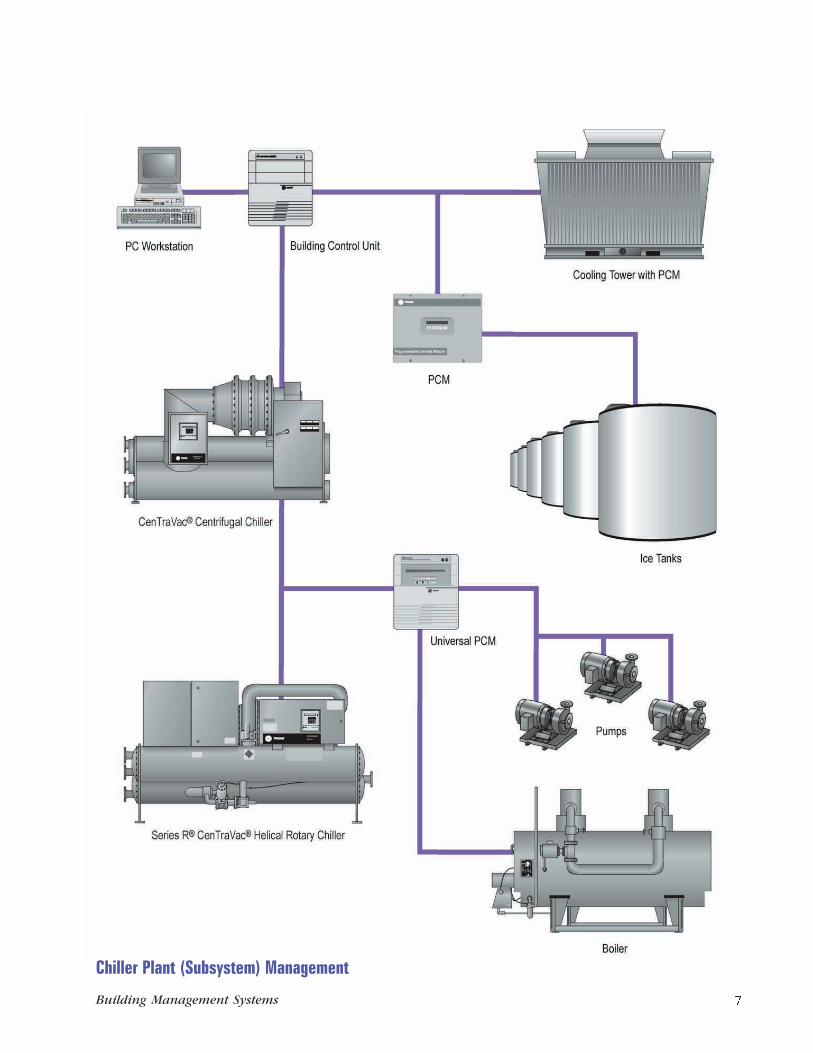
Chiller Plant (Subsystem)ManagementSystems
• Multiple chiller applications
• Ice storage systems
• Dual fuel chiller plants
• Comfort and industrialapplications
Features
• Chiller sequencing
• Rotation changes
• Base, peak, and swing operation
• Soft start
• Individual chiller setpointcalculations
• Failure detection and recovery
• Manual override
• Chiller performance reports
• Remote communications
• Pump and tower control
• Interoperability with BACnet-compatible building managementsystems
• Refrigerant managementmonitoring and reports
• Year 2000 compliant
• Manufactured in an ISO 9001certified facility
Benefits
• Improves chiller efficiency
• Reduces operating costs
• Balances equipment runtimes
• Provides data for managementreports and maintenance
• Uses standard, tested controlroutines for reliable operation
• Recovers safely from power ormachine failures
• Allows orderly startup andshutdown of chillers
• Protects the significantinvestment in the chiller plant
For more information about See page
Building Control Unit ................................................................. 17
Tracer Summit PC Workstation Software .................................. 13
CenTraVac Centrifugal Chiller ................................................... 29
Programmable Control Module ................................................. 24
Series R CenTraVac Helical Rotary Chiller ................................ 29
Universal Programmable Control Module ................................. 24
Lighting Control PanelThe Tracer Lighting Control Panel(LCP) is a microprocessor-basedcontroller that manages buildinglighting circuits according to timeof day schedules and local switchinputs.
The LCP can operate as astandalone device or interface to aTrane Tracer 100 or Tracer Summitbuilding management system;integrating the HVAC and lightingsystems. LCP accessories provideadditional system flexibility andexpansion capabilities.
An LCP telephone interface maycomplement the system byproviding easy override access toany building occupant with atouch-tone telephone.
ICS CapabilityA building operator can use aTracer Summit BCU or a Tracer 100series building management panelto monitor the status of switchedinputs and lighting circuit outputs,provide time of day control, andintegrate lighting control functionsinto the total building managementsystem.
Software CapabilitiesThe LCP database groups relayoutputs into independent lighting
zones, and executes applicationprograms such as blink warningand after-hours operator override.
Zones may be controlled by thefollowing:
• Wall switches
• Occupancy sensors
• Commanded from Tracerapplications programs
• Overridden via local keypad orremote touch-tone telephone
A standalone schedulingapplication allows the LCP toprovide time of day control, evenwhen it is not linked with a Tracerbuilding management system.
Blink Warning
LCP outputs can be programmed toprovide blink warning before theyare switched off at the end of atime of day schedule or overrideperiod. This allows occupants tosafely exit the area or requestadditional override lighting via awall switch input or touch-tonetelephone.
Time of Day Scheduling
When used independently from aTracer building managementsystem, the LCP can beprogrammed to support weekday,weekend, and holiday time of dayscheduling.
LCP Edit Software
Lighting zone circuits can be easilyrezoned without changing fieldwiring by using LCP Edit software.
Hardware DescriptionModular design allows the LCP tobe configured with as few as eightor as many as 32 relay outputs. Arelay expansion card can be addedanytime to extend capacity.
For more information about the LCP, refer toTrane publication BAS-PD-4.
6 Building Management Systems Building Management Systems 27
Application-Specific Unit ControlApplication-specific controllers aredesigned to provide custom controlinterfaces to specific types ofequipment and applications. Thiscontrasts with the general-purposeunit controllers, which provideflexible control options for avariety of equipment.
Terminal Unit ControllerThe Terminal Unit Controller(TUC) is a microprocessor-baseddirect digital controller that cancontrol a range of air conditioningequipment including:
• Fan coils
• Unit ventilators
• Water source heat pumps
• Blower coil air handling units
ICS CapabilitiesWhen linked to a Trane Tracersystem, the TUC provides buildingoperators with centralized buildingmanagement. Using a datacommunications link, you can
connect TUCs to Tracer Summit,Tracer 100i, or Tracer L panels.These panels monitor theoperation of TUC equipment andother unit controllers that are partof a Trane building managementsystem. Tracer systems providecentralized control of equipment,including coordination of setpointsand schedules.
Software CapabilitiesTUCs are proportional integralderivative (PID) control algorithmsspecifically developed for theequipment types listed above, toprovide accurate and reliablecontrol operation.
The TUC is configurable to provideseveral different predefined controlschemes, including 2-pipe or 4-pipevalve control, face and bypassdamper control, compressorcontrol, and economizer control.The TUC is configurable fordifferent input and output devices,
such as 2-position, floating, ormodulating valves.
The TUC can be applied as a field-installed controller to retrofitexisting air conditioningequipment, including installation innon-Trane equipment. The TUC isalso available factory-installed,wired, and tested in Trane airconditioning equipment.
Hardware DescriptionTwo versions of the TUC areavailable for field installation:
• Standard ambient:NEMA Type 1 resin enclosure(32 to 120°F, 0 to 49°C)
• Extended ambient:NEMA Type 1 painted metalenclosure (-40 to 158°F, -40 to70°C)
For more information about the TUC, refer toTrane publication BAS-PD-7.
Chiller Plant (Subsystem) Management
26 Building Management Systems Building Management Systems 7
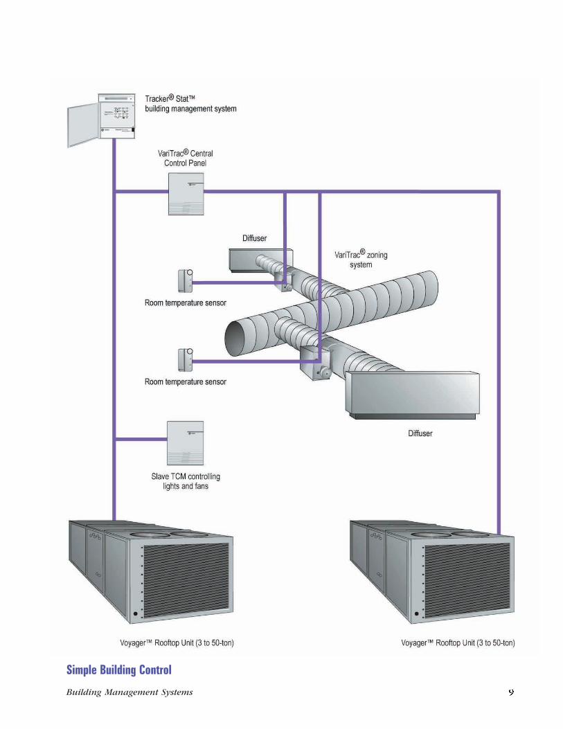
Simple Building ControlSystems
• Light commercial unitary systems
Building Size
• Small to mid-size
Features
• Time of day scheduling
• Optimal start
• Trend logs
• Demand limiting
• Timed override
• Remote communications
• French or Spanish alternatelanguage display
• Fahrenheit or Celsius alternatetemperature display
• Alarm log
• Year 2000 compliant
• Manufactured in an ISO 9001certified facility
Benefits
• Easy-to-use, affordable buildingcontrol for light commercialunitary buildings
• Efficiently matches equipmentoperating times to comfort needs
• Provides monitoring and controleither onsite or from a remotelocation
• Multiple language supportsuitable for internationalinstallations
• Allows the flexibility totemporarily turn on equipmentafter hours
• Reduces peak power demandwithout jeopardizing occupantcomfort
• Can operate from the localkeypad or from a personalcomputer
For more information about See page
Room Temperature Sensor ......................................................... 31
Thermostat Control Module ...................................................... 23
Tracker Stat Building Management System ............................... 20
VariTrac Central Control Panel .................................................. 21
VariTrac Zoning System ............................................................. 20
Voyager Rooftop Unit (3- to 50-ton) .......................................... 30
100 series (L, 100, and 100i) andthe Tracer Summit family ofproducts via an ICS communicationlink.
Software CapabilitiesLike the PCM, the Universal PCMhas the flexibility of customizedcontrol sequences using UPCM EditSoftware. Each Universal PCMsupports 25 PCL routines and 20DDC loops, which can execute at amaximum frequency of onesecond.
Operator-defined PCL routines canperform logical and mathematicalcalculations, and can beautomatically executed or initiatedby an event such as a binary inputchange-of-state or an analog inputhigh or low limit. Each PCL routinecan be manually executed, onestatement at a time, in a special testmode to allow the operator toverify program logic.
DDC loops provide proportional,integral, and derivative (PID)control of analog output devices.PID gains are operator-defined asconstants or as variables calculatedin the PCL routines. The operator
can graphically plot each DDC loopoperation via the UPCM Editsoftware, to assist in optimizing theperformance of controlled devices.UPCM Edit software also offers thefollowing capabilities:
• Current point status screensprovide the status of eachavailable hardware and softwarepoint. Diagnostic informationabout each hardware point is alsoavailable.
• Optional manual overrides oneach output card are available.The manual override on a binaryoutput card is an On/Off/Autoswitch. The manual override onan analog output card is apotentiometer.
• The optional LCD providesmonitoring capability and theability to override pointsconnected to a Universal PCM.This backlit, 2-line by 40-character display provides anoperator interface via eightfunction keys, and includes fouroperator-definable status displayscapable of displaying 16 pointseach. A fifth display includes
Universal PCM status anddiagnostics.
• A calendar/time clock isincluded with the Universal PCM.This clock allows the UniversalPCM to completely recover froma power failure with the correcttime and data. The clock/calendar is backed by a supercapacitor for seven days undernormal operating conditions.
• Modular packaging of theUniversal PCM improvesefficiency and makes job siteinstallation easy.
Hardware DescriptionThree versions of the UniversalPCM are available:
• Standard ambient:NEMA Type 1 metal enclosureconsisting of a steel backplaneand a resin cover (32 to 122°F,0 to 50°C)
• Extended ambient:NEMA Type 1 metal enclosureconsisting of a steel backplaneand a resin cover (-40 to 158°F,-40 to 70°C)
• Weatherproof:NEMA Type 4 metal enclosuresuitable for outdoor use (-40 to158°F, -40 to 70°C)
In addition to the enclosures listedabove, a unit frame mount is alsoavailable. The Universal PCM is UL-approved as a modular energymanagement panel, allowing fieldassembly of the modular partswhile maintaining UL approval.
The Universal PCM supports up tosix operator-selectable, input/output cards (each with 6 points)for a total of 36 points.
For more information about the Universal PCM,refer to Trane publication BAS-PD-5.
8 Building Management Systems Building Management Systems 25
Simple Building Control
Programmable Control ModuleA Programmable Control Module(PCM) provides direct digitalcontrol and monitoring for a widerange of HVAC and otherapplications. Typical uses includecontrolling air handling equipment,interfacing with water chillingunits and boiler systems, andcontrolling pumps and coolingtowers.
ICS CapabilityThe PCM extends the Trane ICStechnology to existing, auxiliary,and non-Trane equipment. A PCMcommunicates with a Tracerbuilding control system over asingle communication link.
Software CapabilitiesThe PCM has the flexibility toprovide custom standalone controlsequences using Process ControlLanguage (PCL). The PCL routinesare programmable and can performlogical and mathematicalcalculations.
The PCM also provides directdigital control (DDC) loops, whichare separate software modules,enabling proportional, integral, andderivative (PID) control of
modulating devices. The operatorcan define PID gains along withhigh and low output limits. ThePCL routines and DDC loops canexecute as frequently as once everyfive seconds.
Both the PCL and DDC softwareprovide special testing capabilitiesfor the custom control sequences.Each PCL routine can be manuallyexecuted, one statement at a time,in a special test mode to allow theoperator to verify the programlogic. The performance of eachDDC loop can be graphicallyplotted to assist the operator intuning the loop.
PCM programs are written andcompiled on a PC using PCM Editsoftware.
This software also allows theoperator to access the PCM toperform the following functions:
• Modify parameters
• Edit the display setup
• View input/output status
• Use the PCL test function
• Plot DDC loops
• Manually control the PCMoutputs
Hardware DescriptionThree versions of the PCM areavailable:
• Standard ambient:NEMA Type 1 metal enclosure(32 to 120°F, 0 to 49°C)
• Extended ambient:NEMA Type 1 metal enclosure(-40 to 158°F, -40 to 70°C)
• Weatherproof:NEMA Type 4 metal enclosuresuitable for outdoor use(-40 to 158°F, -40 to 70°C)
An optional display and keypadinclude a 2-line by 20-characterLCD that can display up to 32status and control points.
For more information about the PCM, refer toTrane publication BAS-TS-43.
Universal ProgrammableControl ModuleThe Universal ProgrammableControl Module, or Universal PCM,is a programmable, direct digitalcontroller that provides controland monitoring for a wide range ofequipment. Typical uses includecontrolling air handling units,monitoring chiller plants includingpumps and cooling towers, andserving as a central point gatheringpanel.
ICS CapabilityAs part of the ICS family and as anextension of the existing PCM, theUniversal PCM provides flexible,independent control for a variety ofapplications. Because of itsflexibility, the Universal PCM canprovide control of both Trane andnon-Trane products. The UniversalPCM communicates with the Tracer
24 Building Management Systems Building Management Systems 9
General-Purpose Unit ControlGeneral-purpose controllersprovide the capability to tie Traneequipment without unit controlmodules and non-Trane equipmentinto the Trane communicationnetwork. Products include theThermostat Control Module,Programmable Control Module, andthe Universal ProgrammableControl Module.
Thermostat Control ModuleThe Thermostat Control Module(TCM) provides a basic yetpowerful interface between TracerSummit, Tracer 100 series, orTracker systems and mechanicalequipment.
The TCM can extend the IntegratedComfort system (ICS) technologyto existing, auxiliary, and non-Traneequipment. The TCMcommunicates with a buildingcontroller over a singlecommunication link.
ICS CapabilityThe TCM provides an interfacebetween the building control paneland equipment not having TraneUnit Control Modules (UCMs), suchas lighting, fans, and non-Traneunitary equipment normallyoperated by a standard thermostat.
Software CapabilitiesThe TCM can function either as a 2-stage heat/2-stage cool thermostatfor air conditioning units and heatpumps, or as a provider of slavepoints for the buildingmanagement panel.
In thermostat mode, the TCMmonitors its sensors and controlsits outputs like a wall thermostat.The TCM can be configured aseither a 2-stage heat/2-stage cool airconditioning thermostat or a heatpump thermostat. This controlresides in the TCM, and the TCMcan operate standalone (withoutthe building management panel)during system startup or whenthere is a communication loss.
In slave mode, the buildingcontroller monitors the TCM inputsand directly controls the TCMoutputs. The TCM input andoutput points function as thoughthey are hardwired, generic pointson the building control panel.
The building control panelprovides control such as time ofday scheduling and demandlimiting.
See the appropriate BuildingControl section of this catalog fordetails on each panel’s capabilities.
Hardware DescriptionThree versions of the TCM areavailable:
• Standard ambient:Resin enclosure (32 to 120°F, 0 to49°C)
• Extended ambient:NEMA Type 1 metal enclosure(-40 to 158°F, -40 to 70°C)
• Weatherproof:NEMA Type 4 metal enclosuresuitable for outdoor use(-40 to 158°F, -40 to 70°C)
For more information about the TCM, refer toTrane publication BAS-TS-32.
10 Building Management Systems Building Management Systems 23
The system can provide multipleOn/Off time periods per day foreach of the seven weekdays. It alsocan provide:
• Holiday schedules and multipleholiday dates
• Exception day schedules
• Automatic daylight saving time
• Optimal start by group
Setpoint Control
The system allows the operator tocontrol setpoints for all VariTraczone UCMs. Setpoint controlincludes occupied and unoccupiedheating and cooling setpoints, andair volume minimum andmaximum setpoints. If desired, usea setpoint control mounted on thezone sensor. The setpoint knob canbe enabled and disabled via theTracer Summit, Tracer 100, orTracker system. The operatingrange of the setpoint knob can belimited to maintain system stabilitywhile still allowing for occupantcomfort control.
After Hours Override
Use either a space-mountedoverride button, or the Tracker,Tracer Summit, or Tracer 100system to temporarily provideoverride from the unoccupied tothe occupied mode. The systemcan also specify the length of theoverride period. An override for aspecific zone becomes an overridefor its group. The associated HVACunit operates in the occupied modefor the duration of the overrideperiod.
Group Control
The Tracker, Tracer Summit, orTracer 100 system enables accessto overrides by group. This allowsthe operator to manually controlthe groups’ occupied/unoccupiedmode, damper position override,and VAV terminal unit heater andfan mode if available. It also
provides for operation of aventilation cycle when the HVACunit is in a zero energy state. Thisprovides greater zone ventilationcapability without affectingcomfort.
System Status
The current operating status of theVariTrac system can be accessedthrough the Tracker or TracerSummit, or Tracer 100 system. Theoperator can view a servicesummary of the entire VariTracsystem at a glance, a more detailedview of each zone, or the currentoperating status of the HVAC unit.
Alarming and Alarm Log
The Tracker, Tracer Summit, orTracer 100 system has thecapability of monitoring VariTracfor system and zone alarms. Suchthings as sensor failure orcommunication loss can bemonitored. Custom alarms are alsoavailable. The system retains a listof past alarms in an alarm log foroperator review. If a Trane Voyagerrooftop is attached to the VariTracsystem, Voyager alarms can bemonitored.
For more information about the VariTrac II CCP,refer to Trane publication BAS-TS-73.
22 Building Management Systems Building Management Systems 11
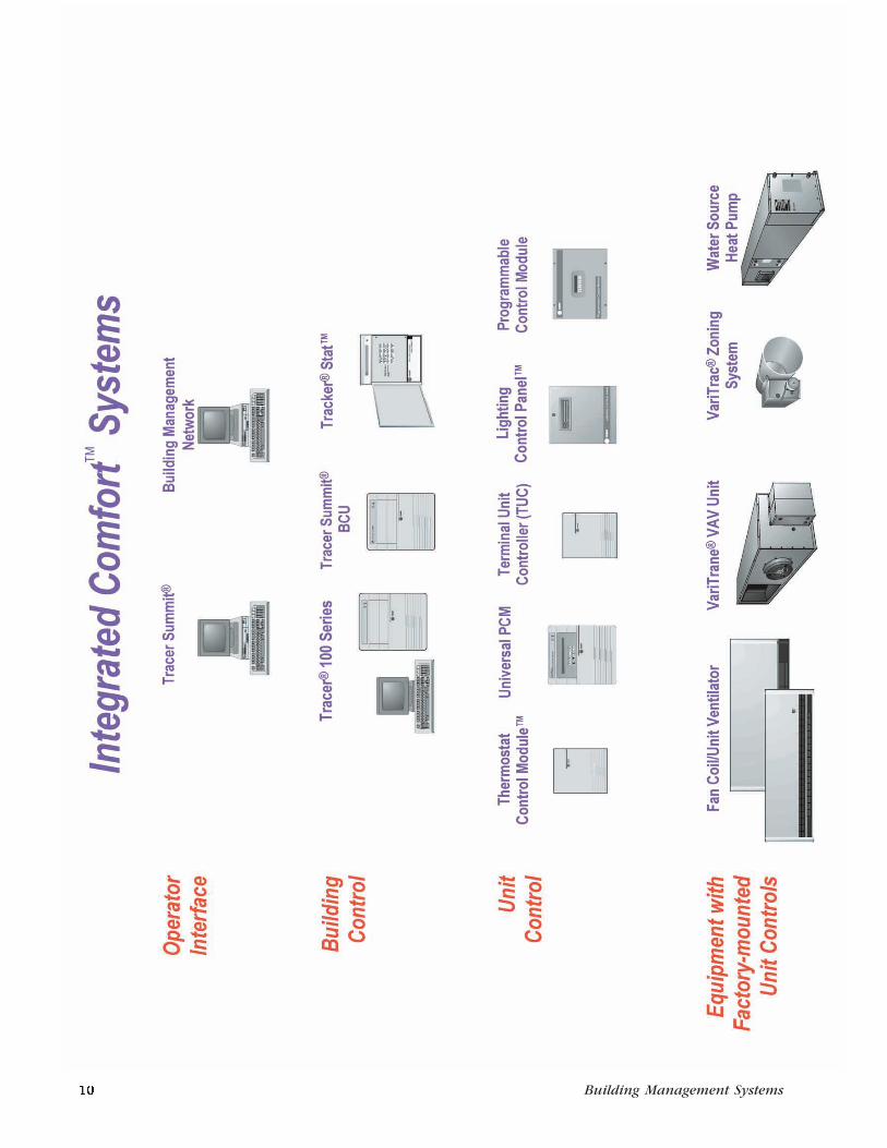
Trane is uniquely qualified toimplement system-wide strategiesfor energy efficiency, refrigerantmanagement, and indoor air qualitybased on expertise gained fromthousands of building automationinstallations and more than 80years as an HVAC systems provider.
Trane’s Integrated Comfort system(ICS) architecture integratesoperator workstations, buildingmanagement panels, and HVACequipment with microprocessor-based control modules for totalbuilding operating efficiency andcomfort. The ICS architecture alsointerfaces with other buildingsystems, such as fire alarm andlighting control.
The foldout on the previous pageillustrates the three levels of an ICSarchitecture:
• Operator interface
• Building control
• Unit control
Operator InterfacePC-based operator workstationsprovide an advanced graphicalinterface that enables operators toperform building operationfunctions quickly with minimalexperience and training. Thesetasks include:
• Viewing the status of thebuilding
• Changing setpoints
• Viewing and modifying schedules
• Responding to alarms
• Viewing historical reportinformation
Building ControlBuilding control functionsincluding energy management,equipment coordination, and alarmprocessing are performed by TracerSummit, Tracer 100 series, orTracker building managementpanels. These panels may belocated in a single facility or inremote buildings with dial-upaccess for communication.
ICS ArchitectureWith thousands of buildingmanagement panels in operation,the full line of Trane buildingmanagement systems is proventechnology.
Unit ControlTrane microprocessor-based unitcontrol modules provide pressure,temperature, and flow control ofHVAC equipment, in addition tomaking comprehensive diagnosticinformation available to buildingmanagement system operators.These Unit Control Modules(UCMs) are factory-mounted on abroad range of Trane equipment.
Auxiliary equipment withoutfactory-mounted UCMs, such ascooling towers, pumps, boilers, andnon-Trane HVAC equipment, can belinked through Trane field-installedcontrollers. These standalonedevices are the ideal base for theHVAC control system upgrades thatare often part of major facilityrenovations.
Remote OperationsThe Tracker system has advancedcommunication and operationcapability via a directly connectededit device, or remotely via anoptional internal modem. TheTracker features a standard RS-232port for connecting the editterminal. All status and setupfeatures previously discussed areaccessible through the RS-232 portor modem, along with theseadditional capabilities:
• Trend logs (up to 8) are availableto monitor any analog input inthe system.
• Custom alarms (up to 24) can beconfigured in addition to thestandard alarm list. These alarmscan be configured for automaticdial out via modem for remotealarm notification.
• Demand limiting . The Stat 16model is capable of demandmonitoring and limiting up to 24loads. All HVAC loads utilizetemperature-compensateddemand control to insureoccupant comfort. Twenty-fourhour and 35-day energy historyusage logs are available toprovide the operator withhistorical data on kW peaks andkWh consumption.
For more information about Tracker, refer toTrane publications BAS-TS-47 and BAS-S-18.
Simple Zoning ControlThe VariTrac II comfort controlsystem provides individualtemperature control to eachcomfort zone in a building whileusing the same single zone airconditioning unit. The VariTrac IIalso varies the flow of supply air toeach zone, providing the heating
and cooling capacity required tomatch the load in each specificzone.
ICS CapabilityThe VariTrac II Central ControlPanel (CCP) interfaces with theTracker, Tracer Summit, or Tracer100 series building managementsystem. It provides control,monitoring, and diagnostics of theindividual VariTrac dampers, CCP,and corresponding HVAC unit.
Software CapabilitiesThe VariTrac II CCP scans the zoneUCMs to determine the deviationsfrom setpoint, length of deviation,time from last heat or coolchangeover, and number of zonesrequiring heating or cooling. Basedon this information, the CCP selectsthe system heat or cool mode andstages of capacity. The CCP alsomonitors the system airtemperature to ensure that highand low temperature limits aremaintained.
The CCP monitors system airvelocity or static pressure and
VariTrac damper position to controlduct air pressure, and to maintainproper air velocity through theHVAC unit.
Group Control of ZonesAll VariTrac UCM zone dampers ona system can be designated as amember of one or four groups. Allgroup members respond togetherto group commands such as timedoverride, time of day control, airflow control overrides, andventilation settings.
Tracker, Tracer Summit, and Tracer100 Series Operating CapabilitiesOccupied/Unoccupied Mode
The Tracker, Tracer Summit, orTracer 100 series panel providestime of day control for the VariTracII zone groups. Each group on aVariTrac system can be individuallyscheduled, enabling greaterscheduling flexibility of each HVACsystem. When any group is in theoccupied mode, the associatedHVAC unit operates in theoccupied mode.
12 Building Management Systems Building Management Systems 21
Operator InterfaceTracer Summit and BuildingManagement Network are theoptions available for high-leveloperator interface.
Operator interfaces provide globalcontrol and serve as acommunication link between theoperator and the buildingmanagement panels. Theseoperator interfaces use adistributed processing architecture,which shares information withbuilding control panels and unitcontrollers — the other two levelsof a building automation system.
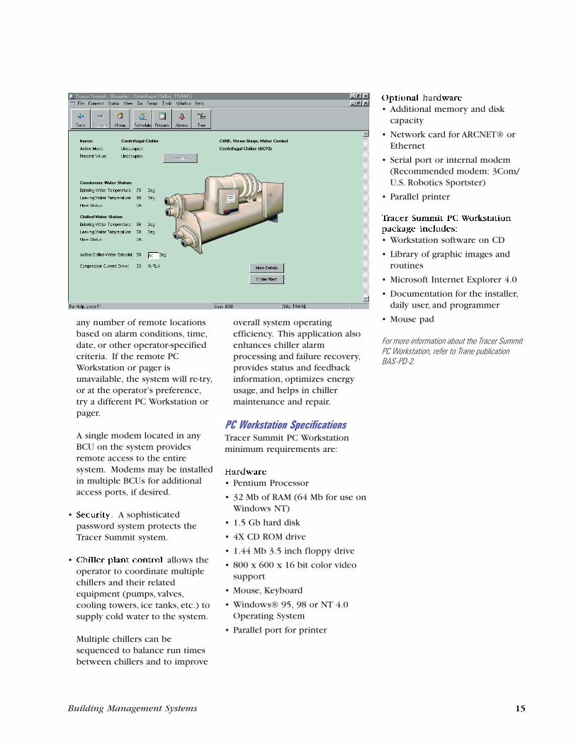
Tracer Summit PC WorkstationThe PC Workstation is the primaryoperator interface for the TracerSummit system. Each PCWorkstation provides a graphicalinterface to system information.The operator can create and editsystem databases, view current andtrended information, acknowledgealarms, and perform operatoroverrides and other operatortransactions from the PCWorkstation. Extensive usabilitytesting incorporated into thedesign of the product makes theTracer Summit PC Workstationsoftware easy to use.
ICS CapabilityThe PC Workstation and the TracerSummit software serve as acommunication link between theoperator and the Building ControlUnits (BCUs) and other equipment.PC Workstations can be connectedand disconnected on an ARCNET orEthernet local area network (LAN)as needed. System operation is notdependent on the PC Workstation.
The Tracer Summit system uses anobject-oriented database thatresides in the BCUs. Each PC
Workstation contains a backupcopy of the fully distributeddatabase. The system is scanned atregular intervals to update thedatabase with changes made fromany PC Workstation.
Operators have the ability to viewthe current setup and configurationfor all unit controllers, inputs, andoutputs for a selected site. Thisinformation can be accessed by aPC Workstation onsite or remotelyvia a modem connection.Operators with the proper securityaccess can edit, add, or deleteobjects. Each editor uses a graphicinterface that allows quick and easyrevision of setup and configurationvalues.
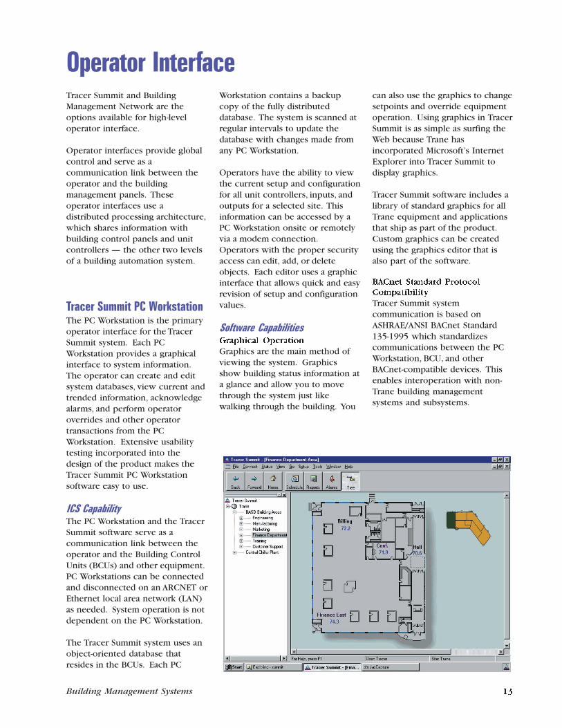
Software CapabilitiesGraphical Operation
Graphics are the main method ofviewing the system. Graphicsshow building status information ata glance and allow you to movethrough the system just likewalking through the building. You
can also use the graphics to changesetpoints and override equipmentoperation. Using graphics in TracerSummit is as simple as surfing theWeb because Trane hasincorporated Microsoft’s InternetExplorer into Tracer Summit todisplay graphics.
Tracer Summit software includes alibrary of standard graphics for allTrane equipment and applicationsthat ship as part of the product.Custom graphics can be createdusing the graphics editor that isalso part of the software.
BACnet Standard Protocol
Compatibility
Tracer Summit systemcommunication is based onASHRAE/ANSI BACnet Standard135-1995 which standardizescommunications between the PCWorkstation, BCU, and otherBACnet-compatible devices. Thisenables interoperation with non-Trane building managementsystems and subsystems.
Tracker and VariTracZoning SystemSimple Building ControlThe Trane Tracker Stat system forlight commercial buildings isdesigned to make effective buildingcontrol simple and affordable. TheTracker provides microelectroniccontrol and monitoring of HVACsystems in new or existingbuildings. Tracker communicateson a serial communication linkwith packaged HVAC equipment,zone controllers, and auxiliarypoints of control, creating a totalIntegrated Comfort system. Trackerprovides the operator withmanagement information andcontrol either onsite or from aremote location.
The three models of the TrackerStat are the Stat 4, Stat 7, and Stat16. Each successive model hasadditional unit capacity and featurecapabilities for different buildingand system needs.
ICS CapabilityTracker can communicate over adata link with the following ICSunits:
• VariTrac II changeover-bypasszoning system with CentralControl Panel (CCP) and VariTraczone dampers
• Voyager packaged HVAC rooftopunits with micro controls
• Thermostat Control Modules
(TCMs) for controlling genericrooftop units, split systems, orheat pumps, and Slave TCMs forcontrolling miscellaneous loadssuch as fans and lights
Front Panel OperationUsing a simple 16-button keypadand 2-line LCD, the onsite operator
can perform the followingfunctions:
• Setpoint control allowsoperators to control heating andcooling setpoints for eachconnected ICS device for boththe occupied and unoccupiedmode.
• Time of day scheduling allowseach unit or load to beindividually scheduled for twoOn/Off periods per day for eachweekday, plus separate holidayand exception day scheduling.
• Holiday dates (up to 24) can bedefined for the Trackerscheduling program.
• Timed override allows theoperator to place any area or unitin the temporary occupied modefor up to four hours.
• Alarms and alarm log . Allconnected ICS devices arecapable of delivering alarms tothe Tracker panel. For example,Voyager Rooftops can alarm suchthings as compressor lockout or
airflow failure. The last 32 alarmevents are maintained in an alarmlog for viewing at the front panel.
Additional Software CapabilitiesIn addition to the operatorinterface capabilities, the Trackeralso provides the followingfeatures:
• Powerfail protection of theclock and database informationfor 14 days without usingbatteries
• Automatic daylight saving time
• Optimal start for each unit
• Unit fan mode control (On/Auto) for Voyager Rooftops andTCMs
• Language display in English,French, or Spanish
• Temperature display inFahrenheit or Celsius
• Password protection of thefront panel control is enabled atthe factory
20 Building Management Systems Building Management Systems 13
Application Programs
Tracer Summit offers the followingcapabilities:
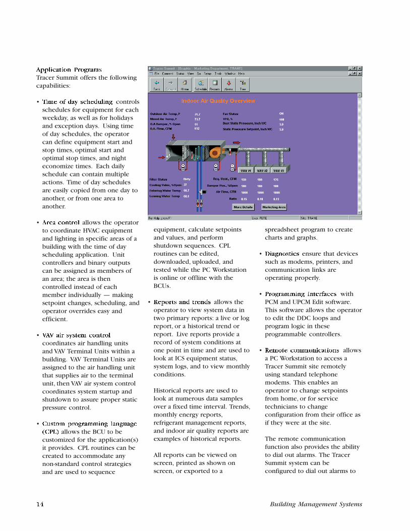
• Time of day scheduling controlsschedules for equipment for eachweekday, as well as for holidaysand exception days. Using timeof day schedules, the operatorcan define equipment start andstop times, optimal start andoptimal stop times, and nighteconomize times. Each dailyschedule can contain multipleactions. Time of day schedulesare easily copied from one day toanother, or from one area toanother.
• Area control allows the operatorto coordinate HVAC equipmentand lighting in specific areas of abuilding with the time of dayscheduling application. Unitcontrollers and binary outputscan be assigned as members ofan area; the area is thencontrolled instead of eachmember individually — makingsetpoint changes, scheduling, andoperator overrides easy andefficient.
• VAV air system control
coordinates air handling unitsand VAV Terminal Units within abuilding. VAV Terminal Units areassigned to the air handling unitthat supplies air to the terminalunit, then VAV air system controlcoordinates system startup andshutdown to assure proper staticpressure control.
• Custom programming language
(CPL) allows the BCU to becustomized for the application(s)it provides. CPL routines can becreated to accommodate anynon-standard control strategiesand are used to sequence
equipment, calculate setpointsand values, and performshutdown sequences. CPLroutines can be edited,downloaded, uploaded, andtested while the PC Workstationis online or offline with theBCUs.
• Reports and trends allows theoperator to view system data intwo primary reports: a live or logreport, or a historical trend orreport. Live reports provide arecord of system conditions atone point in time and are used tolook at ICS equipment status,system logs, and to view monthlyconditions.
Historical reports are used tolook at numerous data samplesover a fixed time interval. Trends,monthly energy reports,refrigerant management reports,and indoor air quality reports areexamples of historical reports.
All reports can be viewed onscreen, printed as shown onscreen, or exported to a
spreadsheet program to createcharts and graphs.
• Diagnostics ensure that devicessuch as modems, printers, andcommunication links areoperating properly.
• Programming interfaces withPCM and UPCM Edit software.This software allows the operatorto edit the DDC loops andprogram logic in theseprogrammable controllers.
• Remote communications allowsa PC Workstation to access aTracer Summit site remotelyusing standard telephonemodems. This enables anoperator to change setpointsfrom home, or for servicetechnicians to changeconfiguration from their office asif they were at the site.
The remote communicationfunction also provides the abilityto dial out alarms. The TracerSummit system can beconfigured to dial out alarms to
• Demand limiting monitors thebuilding’s electrical demand andturns off certain electrical loadsor resets equipment setpointswhen demand exceeds aspecified limit. This helps toreduce peak power demand andsubsequent utility costs. Eachdemand limited load has amaximum off time andtemperature limits to ensureoccupant comfort.
• Chiller sequencing sequencesand automatically rotates up tosix chillers and their associatedpumps to control and monitorchiller operation. Thesequencing program can be usedto control virtually any type ofwater chiller.
• Priority control allows theoperator to define customcontrol sequences that respondto alarm conditions. Prioritycontrol sequences receive thehighest priority, overriding allother control sequences.
• Process control language (PCL)
allows the operator to createcustom control sequences, whichcomplement standard controlprograms by addressing abuilding’s individualrequirements. PCL routinesperform calculations based onreal time data, and can use analogand binary point values, alarmstatus, constants, equationvariables, and mathematical andlogical operations.
• Timed override allows theoperator to temporarily turn on adevice or a specified equipmentgroup that was scheduled off.Timed override can be activatedby a switch on a zone sensor orby a keyboard command from aCRT. Weekly and monthly timed
override reports document after-hours operation.
ICS Status DisplaysAll Trane ICS equipment hasstandard, preformatted displaysthat provide current, historical, anddiagnostic data.
Tracer L and 100i HardwareTracer L, 100i, and CPM contain asingle circuit card that incorporatesprocessor, memory, andcommunications functions. Eachunit includes battery backup,RS-232 communications ports, andan optional internal modem.
ICS system hardware includes theTracer panel, optional system CRT,and optional printer. MultipleTracers can be integrated into asingle system through a unit-to-unitcommunication link.
Tracers can be operated throughthe standard CRT, or optionally,through PC-based Tracer BuildingManagement Network operatorworkstations. BuildingManagement Network provides adynamic operator interface throughthe use of color graphics.
Refer to the Operator Interfacesection of this catalog for moreinformation about BuildingManagement Network.
For more information refer to Trane publicationBAS-S-10.
14 Building Management Systems Building Management Systems 19
any number of remote locationsbased on alarm conditions, time,date, or other operator-specifiedcriteria. If the remote PCWorkstation or pager isunavailable, the system will re-try,or at the operator’s preference,try a different PC Workstation orpager.
A single modem located in anyBCU on the system providesremote access to the entiresystem. Modems may be installedin multiple BCUs for additionalaccess ports, if desired.
• Security. A sophisticatedpassword system protects theTracer Summit system.
• Chiller plant control allows theoperator to coordinate multiplechillers and their relatedequipment (pumps, valves,cooling towers, ice tanks, etc.) tosupply cold water to the system.
Multiple chillers can besequenced to balance run timesbetween chillers and to improve
overall system operatingefficiency. This application alsoenhances chiller alarmprocessing and failure recovery,provides status and feedbackinformation, optimizes energyusage, and helps in chillermaintenance and repair.
PC Workstation SpecificationsTracer Summit PC Workstationminimum requirements are:
Hardware
• Pentium Processor
• 32 Mb of RAM (64 Mb for use onWindows NT)
• 1.5 Gb hard disk
• 4X CD ROM drive
• 1.44 Mb 3.5 inch floppy drive
• 800 x 600 x 16 bit color videosupport
• Mouse, Keyboard
• Windows® 95, 98 or NT 4.0Operating System
• Parallel port for printer
Optional hardware
• Additional memory and diskcapacity
• Network card for ARCNET® orEthernet
• Serial port or internal modem(Recommended modem: 3Com/U.S. Robotics Sportster)
• Parallel printer
Tracer Summit PC Workstation
package includes:
• Workstation software on CD
• Library of graphic images androutines
• Microsoft Internet Explorer 4.0
• Documentation for the installer,daily user, and programmer
• Mouse pad
For more information about the Tracer SummitPC Workstation, refer to Trane publicationBAS-PD-2.
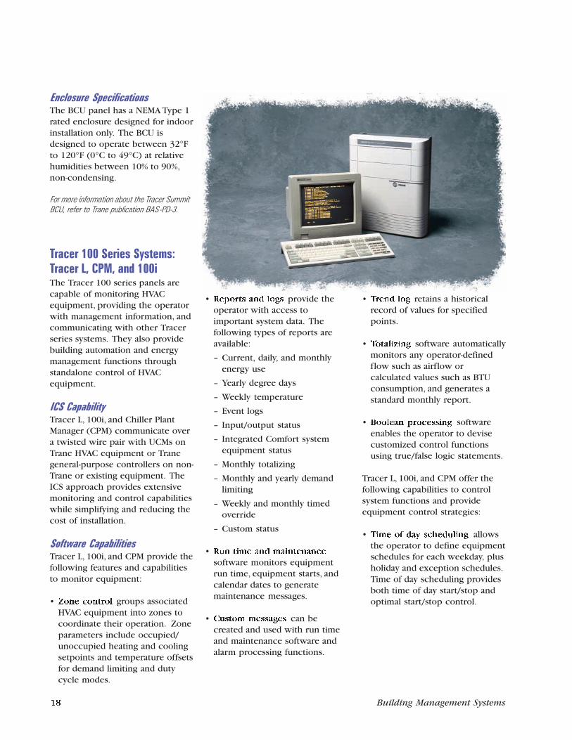
Enclosure SpecificationsThe BCU panel has a NEMA Type 1rated enclosure designed for indoorinstallation only. The BCU isdesigned to operate between 32°Fto 120°F (0°C to 49°C) at relativehumidities between 10% to 90%,non-condensing.
For more information about the Tracer SummitBCU, refer to Trane publication BAS-PD-3.
Tracer 100 Series Systems:Tracer L, CPM, and 100iThe Tracer 100 series panels arecapable of monitoring HVACequipment, providing the operatorwith management information, andcommunicating with other Tracerseries systems. They also providebuilding automation and energymanagement functions throughstandalone control of HVACequipment.
ICS CapabilityTracer L, 100i, and Chiller PlantManager (CPM) communicate overa twisted wire pair with UCMs onTrane HVAC equipment or Tranegeneral-purpose controllers on non-Trane or existing equipment. TheICS approach provides extensivemonitoring and control capabilitieswhile simplifying and reducing thecost of installation.
Software CapabilitiesTracer L, 100i, and CPM provide thefollowing features and capabilitiesto monitor equipment:
• Zone control groups associatedHVAC equipment into zones tocoordinate their operation. Zoneparameters include occupied/unoccupied heating and coolingsetpoints and temperature offsetsfor demand limiting and dutycycle modes.
• Reports and logs provide theoperator with access toimportant system data. Thefollowing types of reports areavailable:
– Current, daily, and monthlyenergy use
– Yearly degree days
– Weekly temperature
– Event logs
– Input/output status
– Integrated Comfort systemequipment status
– Monthly totalizing
– Monthly and yearly demandlimiting
– Weekly and monthly timedoverride
– Custom status
• Run time and maintenance
software monitors equipmentrun time, equipment starts, andcalendar dates to generatemaintenance messages.
• Custom messages can becreated and used with run timeand maintenance software andalarm processing functions.
• Trend log retains a historicalrecord of values for specifiedpoints.
• Totalizing software automaticallymonitors any operator-definedflow such as airflow orcalculated values such as BTUconsumption, and generates astandard monthly report.
• Boolean processing softwareenables the operator to devisecustomized control functionsusing true/false logic statements.
Tracer L, 100i, and CPM offer thefollowing capabilities to controlsystem functions and provideequipment control strategies:
• Time of day scheduling allowsthe operator to define equipmentschedules for each weekday, plusholiday and exception schedules.Time of day scheduling providesboth time of day start/stop andoptimal start/stop control.
18 Building Management Systems Building Management Systems 15
Building Management NetworkBuilding Management Network(BMN) is a software package usedto communicate with Tracer andTracker panels. These panels maybe located in the same facility or indifferent remote facilities.
ICS CapabilityBMN’s communication capabilitiesmake detailed ICS informationavailable. With BMN’s dynamicinterface, an operator can monitorand control up to 120 independentTracer and Tracker systems.
BMN receives specific mechanicalequipment alarm data as it occursfrom remote unit controllers viamodem or from equipment in thesame building. BMN providesdetailed diagnostic informationunique to the equipment involved,including probable servicingsolutions. BMN can also dial out toremote ICS locations automaticallyeach day to collect specific pointdata and usage reports. Anymodification to schedules orsetpoints for a group of buildingscan be easily implemented acrossall Tracer systems.
Software CapabilitiesBMN offers the following softwarecapabilities:
• An event log retains a historicalrecord of events, includingalarms.
• Reports provide the operatorwith access to important energyand billing data. The followingtypes of reports are available:
– Daily and monthly energyusage reports
– HVAC unit controller and zonestatus reports
– Weekly and monthly afterhours usage reports
• A trend log retains a historicalrecord of values for specifiedpoints. This information oftenprovides troubleshootinganswers for service technicians.
• Operator-defined maintenance
messages can be used withalarms or equipment run timelimits to help schedulepreventive maintenance.
• Save and restore software savesprogramming from a Tracer orTracker panel to a disk. A remotepanel can be reprogrammed laterby downloading the savedprogramming.
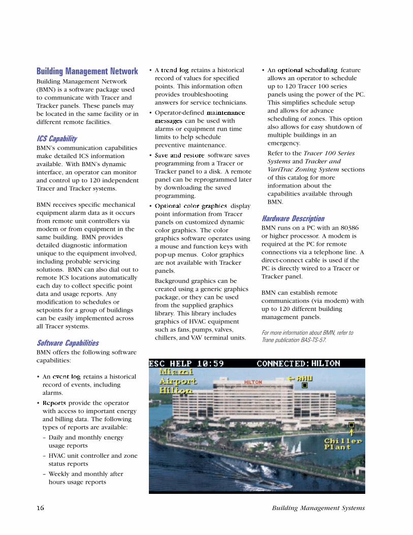
• Optional color graphics displaypoint information from Tracerpanels on customized dynamiccolor graphics. The colorgraphics software operates usinga mouse and function keys withpop-up menus. Color graphicsare not available with Trackerpanels.
Background graphics can becreated using a generic graphicspackage, or they can be usedfrom the supplied graphicslibrary. This library includesgraphics of HVAC equipmentsuch as fans, pumps, valves,chillers, and VAV terminal units.
• An optional scheduling featureallows an operator to scheduleup to 120 Tracer 100 seriespanels using the power of the PC.This simplifies schedule setupand allows for advancescheduling of zones. This optionalso allows for easy shutdown ofmultiple buildings in anemergency.
Refer to the Tracer 100 SeriesSystems and Tracker andVariTrac Zoning System sectionsof this catalog for moreinformation about thecapabilities available throughBMN.
Hardware DescriptionBMN runs on a PC with an 80386or higher processor. A modem isrequired at the PC for remoteconnections via a telephone line. Adirect-connect cable is used if thePC is directly wired to a Tracer orTracker panel.
BMN can establish remotecommunications (via modem) withup to 120 different buildingmanagement panels.
For more information about BMN, refer toTrane publication BAS-TS-57.
Building ControlTracer Summit Building ControlUnits (BCUs), Tracer 100 seriesbuilding management panels, andTracker all monitor and coordinatecontrol of Trane HVAC equipment,non-Trane HVAC equipment, andrelated building systems.
A single Integrated Comfort systemis created by linking multiplebuilding level control panels via acommunications network.
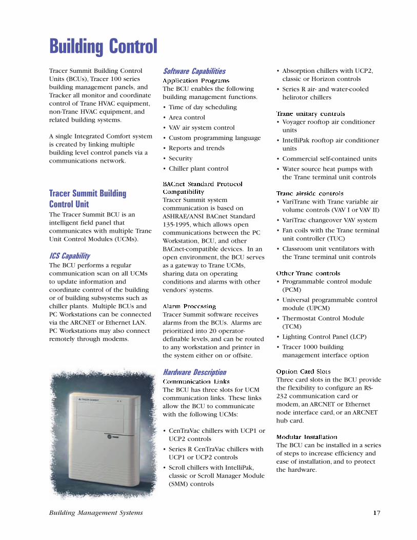
Tracer Summit BuildingControl UnitThe Tracer Summit BCU is anintelligent field panel thatcommunicates with multiple TraneUnit Control Modules (UCMs).
ICS CapabilityThe BCU performs a regularcommunication scan on all UCMsto update information andcoordinate control of the buildingor of building subsystems such aschiller plants. Multiple BCUs andPC Workstations can be connectedvia the ARCNET or Ethernet LAN.PC Workstations may also connectremotely through modems.
Software CapabilitiesApplication Programs
The BCU enables the followingbuilding management functions.
• Time of day scheduling
• Area control
• VAV air system control
• Custom programming language
• Reports and trends
• Security
• Chiller plant control
BACnet Standard ProtocolCompatibility
Tracer Summit systemcommunication is based onASHRAE/ANSI BACnet Standard135-1995, which allows opencommunications between the PCWorkstation, BCU, and otherBACnet-compatible devices. In anopen environment, the BCU servesas a gateway to Trane UCMs,sharing data on operatingconditions and alarms with othervendors’ systems.
Alarm Processing
Tracer Summit software receivesalarms from the BCUs. Alarms areprioritized into 20 operator-definable levels, and can be routedto any workstation and printer inthe system either on or offsite.
Hardware DescriptionCommunication Links
The BCU has three slots for UCMcommunication links. These linksallow the BCU to communicatewith the following UCMs:
• CenTraVac chillers with UCP1 orUCP2 controls
• Series R CenTraVac chillers withUCP1 or UCP2 controls
• Scroll chillers with IntelliPak,classic or Scroll Manager Module(SMM) controls
• Absorption chillers with UCP2,classic or Horizon controls
• Series R air- and water-cooledhelirotor chillers
Trane unitary controls
• Voyager rooftop air conditionerunits
• IntelliPak rooftop air conditionerunits
• Commercial self-contained units
• Water source heat pumps withthe Trane terminal unit controls
Trane airside controls
• VariTrane with Trane variable airvolume controls (VAV I or VAV II)
• VariTrac changeover VAV system
• Fan coils with the Trane terminalunit controller (TUC)
• Classroom unit ventilators withthe Trane terminal unit controls
Other Trane controls
• Programmable control module(PCM)
• Universal programmable controlmodule (UPCM)
• Thermostat Control Module(TCM)
• Lighting Control Panel (LCP)
• Tracer 1000 buildingmanagement interface option
Option Card Slots
Three card slots in the BCU providethe flexibility to configure an RS-232 communication card ormodem, an ARCNET or Ethernetnode interface card, or an ARCNEThub card.
Modular Installation
The BCU can be installed in a seriesof steps to increase efficiency andease of installation, and to protectthe hardware.
16 Building Management Systems Building Management Systems 17
Building Management NetworkBuilding Management Network(BMN) is a software package usedto communicate with Tracer andTracker panels. These panels maybe located in the same facility or indifferent remote facilities.
ICS CapabilityBMN’s communication capabilitiesmake detailed ICS informationavailable. With BMN’s dynamicinterface, an operator can monitorand control up to 120 independentTracer and Tracker systems.
BMN receives specific mechanicalequipment alarm data as it occursfrom remote unit controllers viamodem or from equipment in thesame building. BMN providesdetailed diagnostic informationunique to the equipment involved,including probable servicingsolutions. BMN can also dial out toremote ICS locations automaticallyeach day to collect specific pointdata and usage reports. Anymodification to schedules orsetpoints for a group of buildingscan be easily implemented acrossall Tracer systems.
Software CapabilitiesBMN offers the following softwarecapabilities:
• An event log retains a historicalrecord of events, includingalarms.
• Reports provide the operatorwith access to important energyand billing data. The followingtypes of reports are available:
– Daily and monthly energyusage reports
– HVAC unit controller and zonestatus reports
– Weekly and monthly afterhours usage reports
• A trend log retains a historicalrecord of values for specifiedpoints. This information oftenprovides troubleshootinganswers for service technicians.
• Operator-defined maintenance
messages can be used withalarms or equipment run timelimits to help schedulepreventive maintenance.
• Save and restore software savesprogramming from a Tracer orTracker panel to a disk. A remotepanel can be reprogrammed laterby downloading the savedprogramming.
• Optional color graphics displaypoint information from Tracerpanels on customized dynamiccolor graphics. The colorgraphics software operates usinga mouse and function keys withpop-up menus. Color graphicsare not available with Trackerpanels.
Background graphics can becreated using a generic graphicspackage, or they can be usedfrom the supplied graphicslibrary. This library includesgraphics of HVAC equipmentsuch as fans, pumps, valves,chillers, and VAV terminal units.
• An optional scheduling featureallows an operator to scheduleup to 120 Tracer 100 seriespanels using the power of the PC.This simplifies schedule setupand allows for advancescheduling of zones. This optionalso allows for easy shutdown ofmultiple buildings in anemergency.
Refer to the Tracer 100 SeriesSystems and Tracker andVariTrac Zoning System sectionsof this catalog for moreinformation about thecapabilities available throughBMN.
Hardware DescriptionBMN runs on a PC with an 80386or higher processor. A modem isrequired at the PC for remoteconnections via a telephone line. Adirect-connect cable is used if thePC is directly wired to a Tracer orTracker panel.
BMN can establish remotecommunications (via modem) withup to 120 different buildingmanagement panels.
For more information about BMN, refer toTrane publication BAS-TS-57.
Building ControlTracer Summit Building ControlUnits (BCUs), Tracer 100 seriesbuilding management panels, andTracker all monitor and coordinatecontrol of Trane HVAC equipment,non-Trane HVAC equipment, andrelated building systems.
A single Integrated Comfort systemis created by linking multiplebuilding level control panels via acommunications network.
Tracer Summit BuildingControl UnitThe Tracer Summit BCU is anintelligent field panel thatcommunicates with multiple TraneUnit Control Modules (UCMs).
ICS CapabilityThe BCU performs a regularcommunication scan on all UCMsto update information andcoordinate control of the buildingor of building subsystems such aschiller plants. Multiple BCUs andPC Workstations can be connectedvia the ARCNET or Ethernet LAN.PC Workstations may also connectremotely through modems.
Software CapabilitiesApplication Programs
The BCU enables the followingbuilding management functions.
• Time of day scheduling
• Area control
• VAV air system control
• Custom programming language
• Reports and trends
• Security
• Chiller plant control
BACnet Standard ProtocolCompatibility
Tracer Summit systemcommunication is based onASHRAE/ANSI BACnet Standard135-1995, which allows opencommunications between the PCWorkstation, BCU, and otherBACnet-compatible devices. In anopen environment, the BCU servesas a gateway to Trane UCMs,sharing data on operatingconditions and alarms with othervendors’ systems.
Alarm Processing
Tracer Summit software receivesalarms from the BCUs. Alarms areprioritized into 20 operator-definable levels, and can be routedto any workstation and printer inthe system either on or offsite.
Hardware DescriptionCommunication Links
The BCU has three slots for UCMcommunication links. These linksallow the BCU to communicatewith the following UCMs:
• CenTraVac chillers with UCP1 orUCP2 controls
• Series R CenTraVac chillers withUCP1 or UCP2 controls
• Scroll chillers with IntelliPak,classic or Scroll Manager Module(SMM) controls
• Absorption chillers with UCP2,classic or Horizon controls
• Series R air- and water-cooledhelirotor chillers
Trane unitary controls
• Voyager rooftop air conditionerunits
• IntelliPak rooftop air conditionerunits
• Commercial self-contained units
• Water source heat pumps withthe Trane terminal unit controls
Trane airside controls
• VariTrane with Trane variable airvolume controls (VAV I or VAV II)
• VariTrac changeover VAV system
• Fan coils with the Trane terminalunit controller (TUC)
• Classroom unit ventilators withthe Trane terminal unit controls
Other Trane controls
• Programmable control module(PCM)
• Universal programmable controlmodule (UPCM)
• Thermostat Control Module(TCM)
• Lighting Control Panel (LCP)
• Tracer 1000 buildingmanagement interface option
Option Card Slots
Three card slots in the BCU providethe flexibility to configure an RS-232 communication card ormodem, an ARCNET or Ethernetnode interface card, or an ARCNEThub card.
Modular Installation
The BCU can be installed in a seriesof steps to increase efficiency andease of installation, and to protectthe hardware.
16 Building Management Systems Building Management Systems 17
any number of remote locationsbased on alarm conditions, time,date, or other operator-specifiedcriteria. If the remote PCWorkstation or pager isunavailable, the system will re-try,or at the operator’s preference,try a different PC Workstation orpager.
A single modem located in anyBCU on the system providesremote access to the entiresystem. Modems may be installedin multiple BCUs for additionalaccess ports, if desired.
• Security. A sophisticatedpassword system protects theTracer Summit system.
• Chiller plant control allows theoperator to coordinate multiplechillers and their relatedequipment (pumps, valves,cooling towers, ice tanks, etc.) tosupply cold water to the system.
Multiple chillers can besequenced to balance run timesbetween chillers and to improve
overall system operatingefficiency. This application alsoenhances chiller alarmprocessing and failure recovery,provides status and feedbackinformation, optimizes energyusage, and helps in chillermaintenance and repair.
PC Workstation SpecificationsTracer Summit PC Workstationminimum requirements are:
Hardware
• Pentium Processor
• 32 Mb of RAM (64 Mb for use onWindows NT)
• 1.5 Gb hard disk
• 4X CD ROM drive
• 1.44 Mb 3.5 inch floppy drive
• 800 x 600 x 16 bit color videosupport
• Mouse, Keyboard
• Windows® 95, 98 or NT 4.0Operating System
• Parallel port for printer
Optional hardware
• Additional memory and diskcapacity
• Network card for ARCNET® orEthernet
• Serial port or internal modem(Recommended modem: 3Com/U.S. Robotics Sportster)
• Parallel printer
Tracer Summit PC Workstation
package includes:
• Workstation software on CD
• Library of graphic images androutines
• Microsoft Internet Explorer 4.0
• Documentation for the installer,daily user, and programmer
• Mouse pad
For more information about the Tracer SummitPC Workstation, refer to Trane publicationBAS-PD-2.
Enclosure SpecificationsThe BCU panel has a NEMA Type 1rated enclosure designed for indoorinstallation only. The BCU isdesigned to operate between 32°Fto 120°F (0°C to 49°C) at relativehumidities between 10% to 90%,non-condensing.
For more information about the Tracer SummitBCU, refer to Trane publication BAS-PD-3.
Tracer 100 Series Systems:Tracer L, CPM, and 100iThe Tracer 100 series panels arecapable of monitoring HVACequipment, providing the operatorwith management information, andcommunicating with other Tracerseries systems. They also providebuilding automation and energymanagement functions throughstandalone control of HVACequipment.
ICS CapabilityTracer L, 100i, and Chiller PlantManager (CPM) communicate overa twisted wire pair with UCMs onTrane HVAC equipment or Tranegeneral-purpose controllers on non-Trane or existing equipment. TheICS approach provides extensivemonitoring and control capabilitieswhile simplifying and reducing thecost of installation.
Software CapabilitiesTracer L, 100i, and CPM provide thefollowing features and capabilitiesto monitor equipment:
• Zone control groups associatedHVAC equipment into zones tocoordinate their operation. Zoneparameters include occupied/unoccupied heating and coolingsetpoints and temperature offsetsfor demand limiting and dutycycle modes.
• Reports and logs provide theoperator with access toimportant system data. Thefollowing types of reports areavailable:
– Current, daily, and monthlyenergy use
– Yearly degree days
– Weekly temperature
– Event logs
– Input/output status
– Integrated Comfort systemequipment status
– Monthly totalizing
– Monthly and yearly demandlimiting
– Weekly and monthly timedoverride
– Custom status
• Run time and maintenance
software monitors equipmentrun time, equipment starts, andcalendar dates to generatemaintenance messages.
• Custom messages can becreated and used with run timeand maintenance software andalarm processing functions.
• Trend log retains a historicalrecord of values for specifiedpoints.
• Totalizing software automaticallymonitors any operator-definedflow such as airflow orcalculated values such as BTUconsumption, and generates astandard monthly report.
• Boolean processing softwareenables the operator to devisecustomized control functionsusing true/false logic statements.
Tracer L, 100i, and CPM offer thefollowing capabilities to controlsystem functions and provideequipment control strategies:
• Time of day scheduling allowsthe operator to define equipmentschedules for each weekday, plusholiday and exception schedules.Time of day scheduling providesboth time of day start/stop andoptimal start/stop control.
18 Building Management Systems Building Management Systems 15
Application Programs
Tracer Summit offers the followingcapabilities:
• Time of day scheduling controlsschedules for equipment for eachweekday, as well as for holidaysand exception days. Using timeof day schedules, the operatorcan define equipment start andstop times, optimal start andoptimal stop times, and nighteconomize times. Each dailyschedule can contain multipleactions. Time of day schedulesare easily copied from one day toanother, or from one area toanother.
• Area control allows the operatorto coordinate HVAC equipmentand lighting in specific areas of abuilding with the time of dayscheduling application. Unitcontrollers and binary outputscan be assigned as members ofan area; the area is thencontrolled instead of eachmember individually — makingsetpoint changes, scheduling, andoperator overrides easy andefficient.
• VAV air system control
coordinates air handling unitsand VAV Terminal Units within abuilding. VAV Terminal Units areassigned to the air handling unitthat supplies air to the terminalunit, then VAV air system controlcoordinates system startup andshutdown to assure proper staticpressure control.
• Custom programming language
(CPL) allows the BCU to becustomized for the application(s)it provides. CPL routines can becreated to accommodate anynon-standard control strategiesand are used to sequence
equipment, calculate setpointsand values, and performshutdown sequences. CPLroutines can be edited,downloaded, uploaded, andtested while the PC Workstationis online or offline with theBCUs.
• Reports and trends allows theoperator to view system data intwo primary reports: a live or logreport, or a historical trend orreport. Live reports provide arecord of system conditions atone point in time and are used tolook at ICS equipment status,system logs, and to view monthlyconditions.
Historical reports are used tolook at numerous data samplesover a fixed time interval. Trends,monthly energy reports,refrigerant management reports,and indoor air quality reports areexamples of historical reports.
All reports can be viewed onscreen, printed as shown onscreen, or exported to a
spreadsheet program to createcharts and graphs.
• Diagnostics ensure that devicessuch as modems, printers, andcommunication links areoperating properly.
• Programming interfaces withPCM and UPCM Edit software.This software allows the operatorto edit the DDC loops andprogram logic in theseprogrammable controllers.
• Remote communications allowsa PC Workstation to access aTracer Summit site remotelyusing standard telephonemodems. This enables anoperator to change setpointsfrom home, or for servicetechnicians to changeconfiguration from their office asif they were at the site.
The remote communicationfunction also provides the abilityto dial out alarms. The TracerSummit system can beconfigured to dial out alarms to
• Demand limiting monitors thebuilding’s electrical demand andturns off certain electrical loadsor resets equipment setpointswhen demand exceeds aspecified limit. This helps toreduce peak power demand andsubsequent utility costs. Eachdemand limited load has amaximum off time andtemperature limits to ensureoccupant comfort.
• Chiller sequencing sequencesand automatically rotates up tosix chillers and their associatedpumps to control and monitorchiller operation. Thesequencing program can be usedto control virtually any type ofwater chiller.
• Priority control allows theoperator to define customcontrol sequences that respondto alarm conditions. Prioritycontrol sequences receive thehighest priority, overriding allother control sequences.
• Process control language (PCL)
allows the operator to createcustom control sequences, whichcomplement standard controlprograms by addressing abuilding’s individualrequirements. PCL routinesperform calculations based onreal time data, and can use analogand binary point values, alarmstatus, constants, equationvariables, and mathematical andlogical operations.
• Timed override allows theoperator to temporarily turn on adevice or a specified equipmentgroup that was scheduled off.Timed override can be activatedby a switch on a zone sensor orby a keyboard command from aCRT. Weekly and monthly timed
override reports document after-hours operation.
ICS Status DisplaysAll Trane ICS equipment hasstandard, preformatted displaysthat provide current, historical, anddiagnostic data.
Tracer L and 100i HardwareTracer L, 100i, and CPM contain asingle circuit card that incorporatesprocessor, memory, andcommunications functions. Eachunit includes battery backup,RS-232 communications ports, andan optional internal modem.
ICS system hardware includes theTracer panel, optional system CRT,and optional printer. MultipleTracers can be integrated into asingle system through a unit-to-unitcommunication link.
Tracers can be operated throughthe standard CRT, or optionally,through PC-based Tracer BuildingManagement Network operatorworkstations. BuildingManagement Network provides adynamic operator interface throughthe use of color graphics.
Refer to the Operator Interfacesection of this catalog for moreinformation about BuildingManagement Network.
For more information refer to Trane publicationBAS-S-10.
14 Building Management Systems Building Management Systems 19
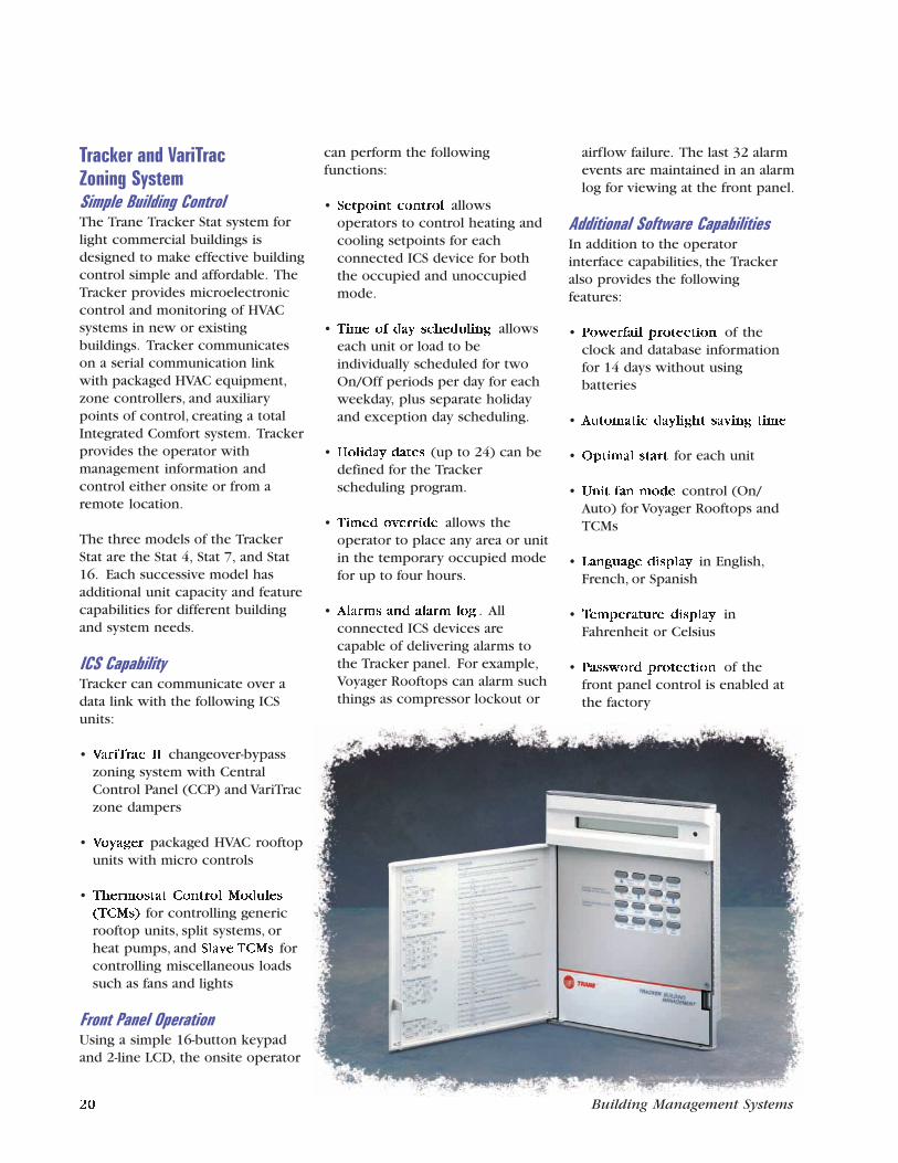
Operator InterfaceTracer Summit and BuildingManagement Network are theoptions available for high-leveloperator interface.
Operator interfaces provide globalcontrol and serve as acommunication link between theoperator and the buildingmanagement panels. Theseoperator interfaces use adistributed processing architecture,which shares information withbuilding control panels and unitcontrollers — the other two levelsof a building automation system.
Tracer Summit PC WorkstationThe PC Workstation is the primaryoperator interface for the TracerSummit system. Each PCWorkstation provides a graphicalinterface to system information.The operator can create and editsystem databases, view current andtrended information, acknowledgealarms, and perform operatoroverrides and other operatortransactions from the PCWorkstation. Extensive usabilitytesting incorporated into thedesign of the product makes theTracer Summit PC Workstationsoftware easy to use.
ICS CapabilityThe PC Workstation and the TracerSummit software serve as acommunication link between theoperator and the Building ControlUnits (BCUs) and other equipment.PC Workstations can be connectedand disconnected on an ARCNET orEthernet local area network (LAN)as needed. System operation is notdependent on the PC Workstation.
The Tracer Summit system uses anobject-oriented database thatresides in the BCUs. Each PC
Workstation contains a backupcopy of the fully distributeddatabase. The system is scanned atregular intervals to update thedatabase with changes made fromany PC Workstation.
Operators have the ability to viewthe current setup and configurationfor all unit controllers, inputs, andoutputs for a selected site. Thisinformation can be accessed by aPC Workstation onsite or remotelyvia a modem connection.Operators with the proper securityaccess can edit, add, or deleteobjects. Each editor uses a graphicinterface that allows quick and easyrevision of setup and configurationvalues.
Software CapabilitiesGraphical Operation
Graphics are the main method ofviewing the system. Graphicsshow building status information ata glance and allow you to movethrough the system just likewalking through the building. You
can also use the graphics to changesetpoints and override equipmentoperation. Using graphics in TracerSummit is as simple as surfing theWeb because Trane hasincorporated Microsoft’s InternetExplorer into Tracer Summit todisplay graphics.
Tracer Summit software includes alibrary of standard graphics for allTrane equipment and applicationsthat ship as part of the product.Custom graphics can be createdusing the graphics editor that isalso part of the software.
BACnet Standard Protocol
Compatibility
Tracer Summit systemcommunication is based onASHRAE/ANSI BACnet Standard135-1995 which standardizescommunications between the PCWorkstation, BCU, and otherBACnet-compatible devices. Thisenables interoperation with non-Trane building managementsystems and subsystems.
Tracker and VariTracZoning SystemSimple Building ControlThe Trane Tracker Stat system forlight commercial buildings isdesigned to make effective buildingcontrol simple and affordable. TheTracker provides microelectroniccontrol and monitoring of HVACsystems in new or existingbuildings. Tracker communicateson a serial communication linkwith packaged HVAC equipment,zone controllers, and auxiliarypoints of control, creating a totalIntegrated Comfort system. Trackerprovides the operator withmanagement information andcontrol either onsite or from aremote location.
The three models of the TrackerStat are the Stat 4, Stat 7, and Stat16. Each successive model hasadditional unit capacity and featurecapabilities for different buildingand system needs.
ICS CapabilityTracker can communicate over adata link with the following ICSunits:
• VariTrac II changeover-bypasszoning system with CentralControl Panel (CCP) and VariTraczone dampers
• Voyager packaged HVAC rooftopunits with micro controls
• Thermostat Control Modules
(TCMs) for controlling genericrooftop units, split systems, orheat pumps, and Slave TCMs forcontrolling miscellaneous loadssuch as fans and lights
Front Panel OperationUsing a simple 16-button keypadand 2-line LCD, the onsite operator
can perform the followingfunctions:
• Setpoint control allowsoperators to control heating andcooling setpoints for eachconnected ICS device for boththe occupied and unoccupiedmode.
• Time of day scheduling allowseach unit or load to beindividually scheduled for twoOn/Off periods per day for eachweekday, plus separate holidayand exception day scheduling.
• Holiday dates (up to 24) can bedefined for the Trackerscheduling program.
• Timed override allows theoperator to place any area or unitin the temporary occupied modefor up to four hours.
• Alarms and alarm log . Allconnected ICS devices arecapable of delivering alarms tothe Tracker panel. For example,Voyager Rooftops can alarm suchthings as compressor lockout or
airflow failure. The last 32 alarmevents are maintained in an alarmlog for viewing at the front panel.
Additional Software CapabilitiesIn addition to the operatorinterface capabilities, the Trackeralso provides the followingfeatures:
• Powerfail protection of theclock and database informationfor 14 days without usingbatteries
• Automatic daylight saving time
• Optimal start for each unit
• Unit fan mode control (On/Auto) for Voyager Rooftops andTCMs
• Language display in English,French, or Spanish
• Temperature display inFahrenheit or Celsius
• Password protection of thefront panel control is enabled atthe factory
20 Building Management Systems Building Management Systems 13
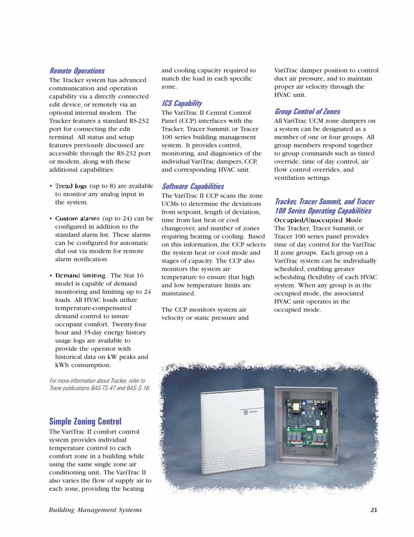
Trane is uniquely qualified toimplement system-wide strategiesfor energy efficiency, refrigerantmanagement, and indoor air qualitybased on expertise gained fromthousands of building automationinstallations and more than 80years as an HVAC systems provider.
Trane’s Integrated Comfort system(ICS) architecture integratesoperator workstations, buildingmanagement panels, and HVACequipment with microprocessor-based control modules for totalbuilding operating efficiency andcomfort. The ICS architecture alsointerfaces with other buildingsystems, such as fire alarm andlighting control.
The foldout on the previous pageillustrates the three levels of an ICSarchitecture:
• Operator interface
• Building control
• Unit control
Operator InterfacePC-based operator workstationsprovide an advanced graphicalinterface that enables operators toperform building operationfunctions quickly with minimalexperience and training. Thesetasks include:
• Viewing the status of thebuilding
• Changing setpoints
• Viewing and modifying schedules
• Responding to alarms
• Viewing historical reportinformation
Building ControlBuilding control functionsincluding energy management,equipment coordination, and alarmprocessing are performed by TracerSummit, Tracer 100 series, orTracker building managementpanels. These panels may belocated in a single facility or inremote buildings with dial-upaccess for communication.
ICS ArchitectureWith thousands of buildingmanagement panels in operation,the full line of Trane buildingmanagement systems is proventechnology.
Unit ControlTrane microprocessor-based unitcontrol modules provide pressure,temperature, and flow control ofHVAC equipment, in addition tomaking comprehensive diagnosticinformation available to buildingmanagement system operators.These Unit Control Modules(UCMs) are factory-mounted on abroad range of Trane equipment.
Auxiliary equipment withoutfactory-mounted UCMs, such ascooling towers, pumps, boilers, andnon-Trane HVAC equipment, can belinked through Trane field-installedcontrollers. These standalonedevices are the ideal base for theHVAC control system upgrades thatare often part of major facilityrenovations.
Remote OperationsThe Tracker system has advancedcommunication and operationcapability via a directly connectededit device, or remotely via anoptional internal modem. TheTracker features a standard RS-232port for connecting the editterminal. All status and setupfeatures previously discussed areaccessible through the RS-232 portor modem, along with theseadditional capabilities:
• Trend logs (up to 8) are availableto monitor any analog input inthe system.
• Custom alarms (up to 24) can beconfigured in addition to thestandard alarm list. These alarmscan be configured for automaticdial out via modem for remotealarm notification.
• Demand limiting . The Stat 16model is capable of demandmonitoring and limiting up to 24loads. All HVAC loads utilizetemperature-compensateddemand control to insureoccupant comfort. Twenty-fourhour and 35-day energy historyusage logs are available toprovide the operator withhistorical data on kW peaks andkWh consumption.
For more information about Tracker, refer toTrane publications BAS-TS-47 and BAS-S-18.
Simple Zoning ControlThe VariTrac II comfort controlsystem provides individualtemperature control to eachcomfort zone in a building whileusing the same single zone airconditioning unit. The VariTrac IIalso varies the flow of supply air toeach zone, providing the heating
and cooling capacity required tomatch the load in each specificzone.
ICS CapabilityThe VariTrac II Central ControlPanel (CCP) interfaces with theTracker, Tracer Summit, or Tracer100 series building managementsystem. It provides control,monitoring, and diagnostics of theindividual VariTrac dampers, CCP,and corresponding HVAC unit.
Software CapabilitiesThe VariTrac II CCP scans the zoneUCMs to determine the deviationsfrom setpoint, length of deviation,time from last heat or coolchangeover, and number of zonesrequiring heating or cooling. Basedon this information, the CCP selectsthe system heat or cool mode andstages of capacity. The CCP alsomonitors the system airtemperature to ensure that highand low temperature limits aremaintained.
The CCP monitors system airvelocity or static pressure and
VariTrac damper position to controlduct air pressure, and to maintainproper air velocity through theHVAC unit.
Group Control of ZonesAll VariTrac UCM zone dampers ona system can be designated as amember of one or four groups. Allgroup members respond togetherto group commands such as timedoverride, time of day control, airflow control overrides, andventilation settings.
Tracker, Tracer Summit, and Tracer100 Series Operating CapabilitiesOccupied/Unoccupied Mode
The Tracker, Tracer Summit, orTracer 100 series panel providestime of day control for the VariTracII zone groups. Each group on aVariTrac system can be individuallyscheduled, enabling greaterscheduling flexibility of each HVACsystem. When any group is in theoccupied mode, the associatedHVAC unit operates in theoccupied mode.
12 Building Management Systems Building Management Systems 21
The system can provide multipleOn/Off time periods per day foreach of the seven weekdays. It alsocan provide:
• Holiday schedules and multipleholiday dates
• Exception day schedules
• Automatic daylight saving time
• Optimal start by group
Setpoint Control
The system allows the operator tocontrol setpoints for all VariTraczone UCMs. Setpoint controlincludes occupied and unoccupiedheating and cooling setpoints, andair volume minimum andmaximum setpoints. If desired, usea setpoint control mounted on thezone sensor. The setpoint knob canbe enabled and disabled via theTracer Summit, Tracer 100, orTracker system. The operatingrange of the setpoint knob can belimited to maintain system stabilitywhile still allowing for occupantcomfort control.
After Hours Override
Use either a space-mountedoverride button, or the Tracker,Tracer Summit, or Tracer 100system to temporarily provideoverride from the unoccupied tothe occupied mode. The systemcan also specify the length of theoverride period. An override for aspecific zone becomes an overridefor its group. The associated HVACunit operates in the occupied modefor the duration of the overrideperiod.
Group Control
The Tracker, Tracer Summit, orTracer 100 system enables accessto overrides by group. This allowsthe operator to manually controlthe groups’ occupied/unoccupiedmode, damper position override,and VAV terminal unit heater andfan mode if available. It also
provides for operation of aventilation cycle when the HVACunit is in a zero energy state. Thisprovides greater zone ventilationcapability without affectingcomfort.
System Status
The current operating status of theVariTrac system can be accessedthrough the Tracker or TracerSummit, or Tracer 100 system. Theoperator can view a servicesummary of the entire VariTracsystem at a glance, a more detailedview of each zone, or the currentoperating status of the HVAC unit.
Alarming and Alarm Log
The Tracker, Tracer Summit, orTracer 100 system has thecapability of monitoring VariTracfor system and zone alarms. Suchthings as sensor failure orcommunication loss can bemonitored. Custom alarms are alsoavailable. The system retains a listof past alarms in an alarm log foroperator review. If a Trane Voyagerrooftop is attached to the VariTracsystem, Voyager alarms can bemonitored.
For more information about the VariTrac II CCP,refer to Trane publication BAS-TS-73.
22 Building Management Systems Building Management Systems 11
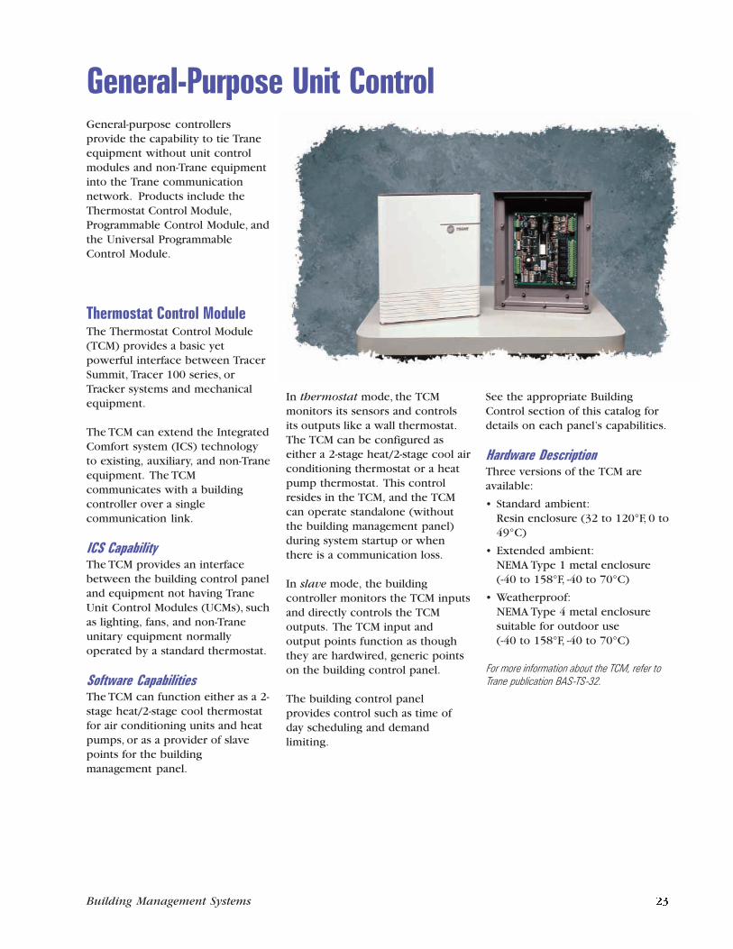
General-Purpose Unit ControlGeneral-purpose controllersprovide the capability to tie Traneequipment without unit controlmodules and non-Trane equipmentinto the Trane communicationnetwork. Products include theThermostat Control Module,Programmable Control Module, andthe Universal ProgrammableControl Module.
Thermostat Control ModuleThe Thermostat Control Module(TCM) provides a basic yetpowerful interface between TracerSummit, Tracer 100 series, orTracker systems and mechanicalequipment.
The TCM can extend the IntegratedComfort system (ICS) technologyto existing, auxiliary, and non-Traneequipment. The TCMcommunicates with a buildingcontroller over a singlecommunication link.
ICS CapabilityThe TCM provides an interfacebetween the building control paneland equipment not having TraneUnit Control Modules (UCMs), suchas lighting, fans, and non-Traneunitary equipment normallyoperated by a standard thermostat.
Software CapabilitiesThe TCM can function either as a 2-stage heat/2-stage cool thermostatfor air conditioning units and heatpumps, or as a provider of slavepoints for the buildingmanagement panel.
In thermostat mode, the TCMmonitors its sensors and controlsits outputs like a wall thermostat.The TCM can be configured aseither a 2-stage heat/2-stage cool airconditioning thermostat or a heatpump thermostat. This controlresides in the TCM, and the TCMcan operate standalone (withoutthe building management panel)during system startup or whenthere is a communication loss.
In slave mode, the buildingcontroller monitors the TCM inputsand directly controls the TCMoutputs. The TCM input andoutput points function as thoughthey are hardwired, generic pointson the building control panel.
The building control panelprovides control such as time ofday scheduling and demandlimiting.
See the appropriate BuildingControl section of this catalog fordetails on each panel’s capabilities.
Hardware DescriptionThree versions of the TCM areavailable:
• Standard ambient:Resin enclosure (32 to 120°F, 0 to49°C)
• Extended ambient:NEMA Type 1 metal enclosure(-40 to 158°F, -40 to 70°C)
• Weatherproof:NEMA Type 4 metal enclosuresuitable for outdoor use(-40 to 158°F, -40 to 70°C)
For more information about the TCM, refer toTrane publication BAS-TS-32.
10 Building Management Systems Building Management Systems 23
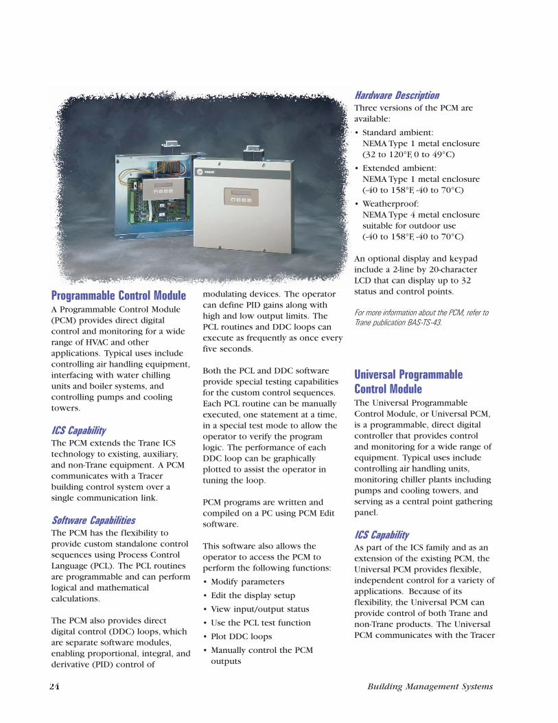
Simple Building Control
Programmable Control ModuleA Programmable Control Module(PCM) provides direct digitalcontrol and monitoring for a widerange of HVAC and otherapplications. Typical uses includecontrolling air handling equipment,interfacing with water chillingunits and boiler systems, andcontrolling pumps and coolingtowers.
ICS CapabilityThe PCM extends the Trane ICStechnology to existing, auxiliary,and non-Trane equipment. A PCMcommunicates with a Tracerbuilding control system over asingle communication link.
Software CapabilitiesThe PCM has the flexibility toprovide custom standalone controlsequences using Process ControlLanguage (PCL). The PCL routinesare programmable and can performlogical and mathematicalcalculations.
The PCM also provides directdigital control (DDC) loops, whichare separate software modules,enabling proportional, integral, andderivative (PID) control of
modulating devices. The operatorcan define PID gains along withhigh and low output limits. ThePCL routines and DDC loops canexecute as frequently as once everyfive seconds.
Both the PCL and DDC softwareprovide special testing capabilitiesfor the custom control sequences.Each PCL routine can be manuallyexecuted, one statement at a time,in a special test mode to allow theoperator to verify the programlogic. The performance of eachDDC loop can be graphicallyplotted to assist the operator intuning the loop.
PCM programs are written andcompiled on a PC using PCM Editsoftware.
This software also allows theoperator to access the PCM toperform the following functions:
• Modify parameters
• Edit the display setup
• View input/output status
• Use the PCL test function
• Plot DDC loops
• Manually control the PCMoutputs
Hardware DescriptionThree versions of the PCM areavailable:
• Standard ambient:NEMA Type 1 metal enclosure(32 to 120°F, 0 to 49°C)
• Extended ambient:NEMA Type 1 metal enclosure(-40 to 158°F, -40 to 70°C)
• Weatherproof:NEMA Type 4 metal enclosuresuitable for outdoor use(-40 to 158°F, -40 to 70°C)
An optional display and keypadinclude a 2-line by 20-characterLCD that can display up to 32status and control points.
For more information about the PCM, refer toTrane publication BAS-TS-43.
Universal ProgrammableControl ModuleThe Universal ProgrammableControl Module, or Universal PCM,is a programmable, direct digitalcontroller that provides controland monitoring for a wide range ofequipment. Typical uses includecontrolling air handling units,monitoring chiller plants includingpumps and cooling towers, andserving as a central point gatheringpanel.
ICS CapabilityAs part of the ICS family and as anextension of the existing PCM, theUniversal PCM provides flexible,independent control for a variety ofapplications. Because of itsflexibility, the Universal PCM canprovide control of both Trane andnon-Trane products. The UniversalPCM communicates with the Tracer
24 Building Management Systems Building Management Systems 9
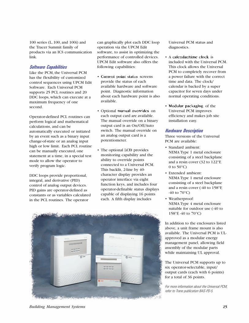
Simple Building ControlSystems
• Light commercial unitary systems
Building Size
• Small to mid-size
Features
• Time of day scheduling
• Optimal start
• Trend logs
• Demand limiting
• Timed override
• Remote communications
• French or Spanish alternatelanguage display
• Fahrenheit or Celsius alternatetemperature display
• Alarm log
• Year 2000 compliant
• Manufactured in an ISO 9001certified facility
Benefits
• Easy-to-use, affordable buildingcontrol for light commercialunitary buildings
• Efficiently matches equipmentoperating times to comfort needs
• Provides monitoring and controleither onsite or from a remotelocation
• Multiple language supportsuitable for internationalinstallations
• Allows the flexibility totemporarily turn on equipmentafter hours
• Reduces peak power demandwithout jeopardizing occupantcomfort
• Can operate from the localkeypad or from a personalcomputer
For more information about See page
Room Temperature Sensor ......................................................... 31
Thermostat Control Module ...................................................... 23
Tracker Stat Building Management System ............................... 20
VariTrac Central Control Panel .................................................. 21
VariTrac Zoning System ............................................................. 20
Voyager Rooftop Unit (3- to 50-ton) .......................................... 30
100 series (L, 100, and 100i) andthe Tracer Summit family ofproducts via an ICS communicationlink.
Software CapabilitiesLike the PCM, the Universal PCMhas the flexibility of customizedcontrol sequences using UPCM EditSoftware. Each Universal PCMsupports 25 PCL routines and 20DDC loops, which can execute at amaximum frequency of onesecond.
Operator-defined PCL routines canperform logical and mathematicalcalculations, and can beautomatically executed or initiatedby an event such as a binary inputchange-of-state or an analog inputhigh or low limit. Each PCL routinecan be manually executed, onestatement at a time, in a special testmode to allow the operator toverify program logic.
DDC loops provide proportional,integral, and derivative (PID)control of analog output devices.PID gains are operator-defined asconstants or as variables calculatedin the PCL routines. The operator
can graphically plot each DDC loopoperation via the UPCM Editsoftware, to assist in optimizing theperformance of controlled devices.UPCM Edit software also offers thefollowing capabilities:
• Current point status screensprovide the status of eachavailable hardware and softwarepoint. Diagnostic informationabout each hardware point is alsoavailable.
• Optional manual overrides oneach output card are available.The manual override on a binaryoutput card is an On/Off/Autoswitch. The manual override onan analog output card is apotentiometer.
• The optional LCD providesmonitoring capability and theability to override pointsconnected to a Universal PCM.This backlit, 2-line by 40-character display provides anoperator interface via eightfunction keys, and includes fouroperator-definable status displayscapable of displaying 16 pointseach. A fifth display includes
Universal PCM status anddiagnostics.
• A calendar/time clock isincluded with the Universal PCM.This clock allows the UniversalPCM to completely recover froma power failure with the correcttime and data. The clock/calendar is backed by a supercapacitor for seven days undernormal operating conditions.
• Modular packaging of theUniversal PCM improvesefficiency and makes job siteinstallation easy.
Hardware DescriptionThree versions of the UniversalPCM are available:
• Standard ambient:NEMA Type 1 metal enclosureconsisting of a steel backplaneand a resin cover (32 to 122°F,0 to 50°C)
• Extended ambient:NEMA Type 1 metal enclosureconsisting of a steel backplaneand a resin cover (-40 to 158°F,-40 to 70°C)
• Weatherproof:NEMA Type 4 metal enclosuresuitable for outdoor use (-40 to158°F, -40 to 70°C)
In addition to the enclosures listedabove, a unit frame mount is alsoavailable. The Universal PCM is UL-approved as a modular energymanagement panel, allowing fieldassembly of the modular partswhile maintaining UL approval.
The Universal PCM supports up tosix operator-selectable, input/output cards (each with 6 points)for a total of 36 points.
For more information about the Universal PCM,refer to Trane publication BAS-PD-5.
8 Building Management Systems Building Management Systems 25
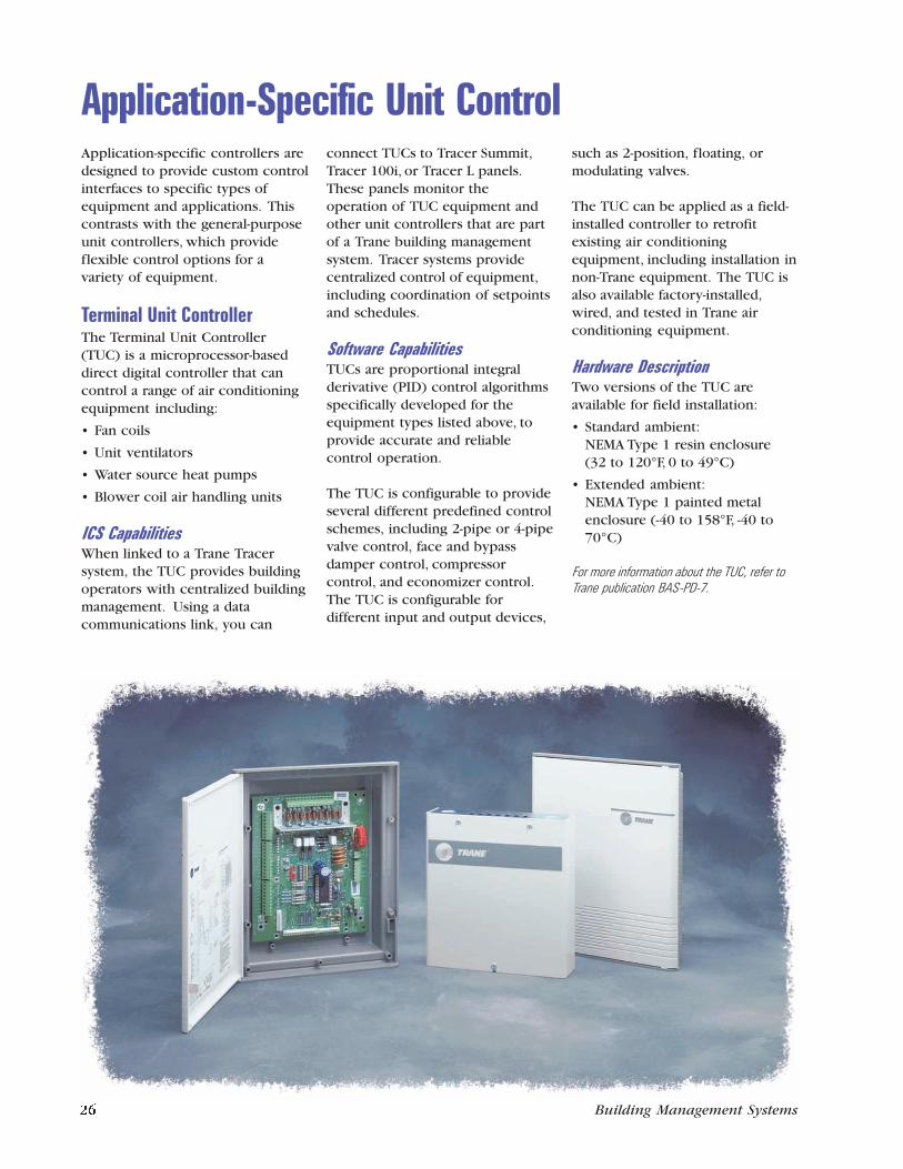
Application-Specific Unit ControlApplication-specific controllers aredesigned to provide custom controlinterfaces to specific types ofequipment and applications. Thiscontrasts with the general-purposeunit controllers, which provideflexible control options for avariety of equipment.
Terminal Unit ControllerThe Terminal Unit Controller(TUC) is a microprocessor-baseddirect digital controller that cancontrol a range of air conditioningequipment including:
• Fan coils
• Unit ventilators
• Water source heat pumps
• Blower coil air handling units
ICS CapabilitiesWhen linked to a Trane Tracersystem, the TUC provides buildingoperators with centralized buildingmanagement. Using a datacommunications link, you can
connect TUCs to Tracer Summit,Tracer 100i, or Tracer L panels.These panels monitor theoperation of TUC equipment andother unit controllers that are partof a Trane building managementsystem. Tracer systems providecentralized control of equipment,including coordination of setpointsand schedules.
Software CapabilitiesTUCs are proportional integralderivative (PID) control algorithmsspecifically developed for theequipment types listed above, toprovide accurate and reliablecontrol operation.
The TUC is configurable to provideseveral different predefined controlschemes, including 2-pipe or 4-pipevalve control, face and bypassdamper control, compressorcontrol, and economizer control.The TUC is configurable fordifferent input and output devices,
such as 2-position, floating, ormodulating valves.
The TUC can be applied as a field-installed controller to retrofitexisting air conditioningequipment, including installation innon-Trane equipment. The TUC isalso available factory-installed,wired, and tested in Trane airconditioning equipment.
Hardware DescriptionTwo versions of the TUC areavailable for field installation:
• Standard ambient:NEMA Type 1 resin enclosure(32 to 120°F, 0 to 49°C)
• Extended ambient:NEMA Type 1 painted metalenclosure (-40 to 158°F, -40 to70°C)
For more information about the TUC, refer toTrane publication BAS-PD-7.
Chiller Plant (Subsystem) Management
26 Building Management Systems Building Management Systems 7
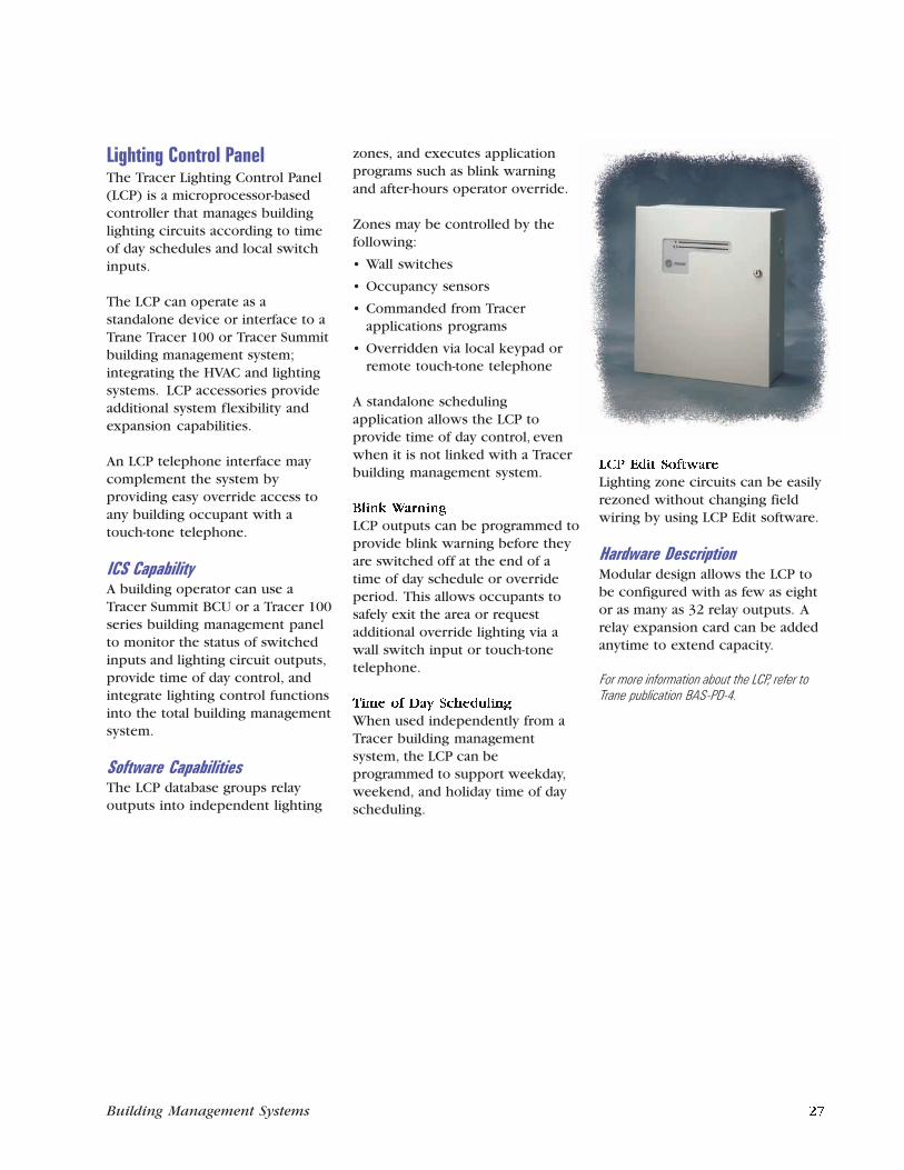
Chiller Plant (Subsystem)ManagementSystems
• Multiple chiller applications
• Ice storage systems
• Dual fuel chiller plants
• Comfort and industrialapplications
Features
• Chiller sequencing
• Rotation changes
• Base, peak, and swing operation
• Soft start
• Individual chiller setpointcalculations
• Failure detection and recovery
• Manual override
• Chiller performance reports
• Remote communications
• Pump and tower control
• Interoperability with BACnet-compatible building managementsystems
• Refrigerant managementmonitoring and reports
• Year 2000 compliant
• Manufactured in an ISO 9001certified facility
Benefits
• Improves chiller efficiency
• Reduces operating costs
• Balances equipment runtimes
• Provides data for managementreports and maintenance
• Uses standard, tested controlroutines for reliable operation
• Recovers safely from power ormachine failures
• Allows orderly startup andshutdown of chillers
• Protects the significantinvestment in the chiller plant
For more information about See page
Building Control Unit ................................................................. 17
Tracer Summit PC Workstation Software .................................. 13
CenTraVac Centrifugal Chiller ................................................... 29
Programmable Control Module ................................................. 24
Series R CenTraVac Helical Rotary Chiller ................................ 29
Universal Programmable Control Module ................................. 24
Lighting Control PanelThe Tracer Lighting Control Panel(LCP) is a microprocessor-basedcontroller that manages buildinglighting circuits according to timeof day schedules and local switchinputs.
The LCP can operate as astandalone device or interface to aTrane Tracer 100 or Tracer Summitbuilding management system;integrating the HVAC and lightingsystems. LCP accessories provideadditional system flexibility andexpansion capabilities.
An LCP telephone interface maycomplement the system byproviding easy override access toany building occupant with atouch-tone telephone.
ICS CapabilityA building operator can use aTracer Summit BCU or a Tracer 100series building management panelto monitor the status of switchedinputs and lighting circuit outputs,provide time of day control, andintegrate lighting control functionsinto the total building managementsystem.
Software CapabilitiesThe LCP database groups relayoutputs into independent lighting
zones, and executes applicationprograms such as blink warningand after-hours operator override.
Zones may be controlled by thefollowing:
• Wall switches
• Occupancy sensors
• Commanded from Tracerapplications programs
• Overridden via local keypad orremote touch-tone telephone
A standalone schedulingapplication allows the LCP toprovide time of day control, evenwhen it is not linked with a Tracerbuilding management system.
Blink Warning
LCP outputs can be programmed toprovide blink warning before theyare switched off at the end of atime of day schedule or overrideperiod. This allows occupants tosafely exit the area or requestadditional override lighting via awall switch input or touch-tonetelephone.
Time of Day Scheduling
When used independently from aTracer building managementsystem, the LCP can beprogrammed to support weekday,weekend, and holiday time of dayscheduling.
LCP Edit Software
Lighting zone circuits can be easilyrezoned without changing fieldwiring by using LCP Edit software.
Hardware DescriptionModular design allows the LCP tobe configured with as few as eightor as many as 32 relay outputs. Arelay expansion card can be addedanytime to extend capacity.
For more information about the LCP, refer toTrane publication BAS-PD-4.
6 Building Management Systems Building Management Systems 27
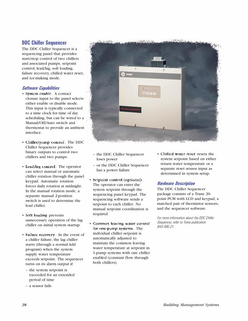
DDC Chiller SequencerThe DDC Chiller Sequencer is asequencing panel that providesstart/stop control of two chillersand associated pumps, setpointcontrol, lead/lag, soft loading,failure recovery, chilled water reset,and ice-making mode.
Software Capabilities• System enable . A contact
closure input to the panel selectseither enable or disable mode.This input is typically connectedto a time clock for time of dayscheduling, but can be wired to aManual/Off/Auto switch andthermostat to provide an ambientinterface.
• Chiller/pump control . The DDCChiller Sequencer providesbinary outputs to control twochillers and two pumps.
• Lead/lag control . The operatorcan select manual or automaticchiller rotation through the panelkeypad. Automatic rotationforces daily rotation at midnight.In the manual rotation mode, aseparate manual 2-positionswitch is used to determine thelead chiller.
• Soft loading preventsunnecessary operation of the lagchiller on initial system startup.
• Failure recovery . In the event ofa chiller failure, the lag chillerstarts (through a normal Addprogram) when the systemsupply water temperatureexceeds setpoint. The sequencerturns on its alarm output if:
– the system setpoint isexceeded for an extendedperiod of time
– a sensor fails
– the DDC Chiller Sequencerloses power
– or the DDC Chiller Sequencerhas a power failure
• Setpoint control (optional) .The operator can enter thesystem setpoint through thesequencing panel keypad. Thesequencing software sends asetpoint to each chiller. Nomanual setpoint coordination isrequired.
• Common leaving water control
for one-pump systems . Theindividual chiller setpoint isautomatically adjusted tomaintain the common leavingwater temperature at setpoint in1-pump systems with one chillerenabled (constant flow throughboth chillers).
• Chilled water reset resets thesystem setpoint based on eitherreturn water temperature or aseparate reset sensor input asdetermined in system setup.
Hardware DescriptionThe DDC Chiller Sequencerpackage consists of a Trane 20-point PCM with LCD and keypad, amatched pair of thermistor sensors,and the sequencer software.
For more information about the DDC ChillerSequencer, refer to Trane publicationBAS-MG-21.
Networked Building Control
28 Building Management Systems Building Management Systems 5
For more information about See page
Air-cooled Series R Chiller ......................................................... 29
Building Control Unit ................................................................. 17
Tracer Summit PC Workstation Software .................................. 13
Modular Climate Changer Air Handler ...................................... 30
Room Temperature Sensor ......................................................... 31
Networked Building ControlSystems
• Applied commercial
• Unitary
Building Size
• Mid-size to large
Features
• Chiller plant control
• High speed ARCNET or EthernetLAN communications betweenpanels
• Graphical user interface
• Remote communications
• Custom programming routines
• Reports and trends
• Time of day scheduling includingoptimum start/stop and nighteconomizing
• Area control to coordinate HVACequipment and lighting
• VAV air system control
• Interoperability with other non-Trane systems and subsystemsusing the BACnetcommunications protocol
• Year 2000 compliant
• Manufactured in an ISO 9001certified facility
Benefits
• Reduced operating costs throughenergy management strategies
• Flexibility to grow with buildingexpansion or remodeling
• Easy-to-learn, easy-to-usegraphical user interface
• Consistent, reliable operationwith standard, pre-engineeredand pre-tested applications
• Easier, faster troubleshootingwith in-depth data and diagnosticinformation
• Advance notice of systemproblems before they become anemergency
• Automatic printing or saving ofreports for analysis or regulatorypurposes
• Quick, at-a-glance graphicalviews of current building status
• Safety and peace of mind withmulti-level operator security
• Truly open communications toBACnet-compatible subsystemsor non-Trane equipment
Factory-Mounted Unit ControlTrane’s Integrated Comfort systems(ICS) concept incorporates thebenefits of factory-mounted, wired,and tested microprocessor controlson each piece of Trane equipmentdescribed in this section. TraneTracer building managementsystems link the HVAC equipmentinto truly integrated comfortsystems that address the criticalissues facing building owners,engineers, and contractors.
ChillersTrane chillers are available with acompressor type, refrigerant type,and capacity to meet nearly anyneed. These chillers are designedto provide a reliable source ofchilled water and are equally suitedfor comfort, industrial, or processapplications.
Unit controllers factory-mountedon Trane chillers provide access toinformation and functions withineach chiller. This access allows thebuilding management productsdescribed in this catalog tooptimize the operation of eachchiller individually and to optimizetheir performance within a chillerplant.
You can link any of the chillerslisted below to a Trane ICS toprovide system-level monitoring,diagnostics, and controlcapabilities, including sequencingchillers as well as controllingpumps and cooling towers:
• CenTraVac Centrifugal Chillers
• Series R CenTraVac HelicalRotary Chillers
• Air-cooled and water-cooledHelical Rotary Chillers
• Air-cooled and water-cooledScroll Chillers
• Absorption Chillers with UCP2,classic or Horizon controls
Refrigerant managementmonitoring and reporting is alsoavailable for applicable chillers.
For more information about Trane chillers, referto Trane publications PROD-DS-1, CTV-DS-1,RLC-DS-1, RLC-DS-2, RLC-DS-4, SLC-DS-1,CG-DS-4, ABS-DS-1, ABS-DS-2, andABS-DS-4.
VariTrane VAV Terminal UnitsVariTrane terminal units areavailable with either pneumatic,electronic, or microprocessorcontrols (DDC/VAV).
Factory-installed DDC/VAV controlsare available with all shutoffterminal units, including parallelfan-powered and series fan-powered units. Dual duct units areequipped with two Unit ControlModules (UCMs) — one for theheat duct and one for the coolduct.
The Variable Air Volume (VAV)UCM is a microprocessor-based,direct digital controller (DDC) forthe VAV terminal unit. It containsthe control logic to modulate theflow of supply air through the VAVterminal in response to the loadrequirements within the VAV zone.The VAV UCM can communicatewith the Tracer 100 series buildingcontrollers and the Tracer SummitBCUs.
For more information about VariTrane VAVterminals, refer to Trane publicationsVAV-D-7 and VAV-DS-9.
Commercial Self ContainedUnitsTrane Commercial Self Containedair conditioners efficiently bridgethe gap between unitary andcentral systems by factory-packaging rugged commercialcomponents in a floor-by-floordecentralized system. Multiple,independent refrigerant circuits —using the 3-D scroll compressor —provide high performanceredundancy. For applicationflexibility, units are factory-equipped for either water-cooled orremote air-cooled condensing.
Acoustically designed for locationnear occupied building spaces, oneor more compact Commercial SelfContained air conditioners arecommonly placed in an equipmentroom on each floor. Supply air isducted to VariTrane VAV terminals.Alternatively, these units can beused with constant volume airsupply systems.
Commercial Self Contained unitsequipped with UCMs can beconnected directly to a TracerSummit BCU or Tracer 100 seriescontroller. These systems providecontrol, monitoring, anddiagnostics capabiliti--––es.
For more information about Commercial SelfContained Units, refer to Trane publicationPKG-DS-6.
4 Building Management Systems Building Management Systems 29
IntelliPak Rooftop UnitsThe 20- to 130-ton IntelliPakRooftop is a self-contained heatingand cooling air handling unit. TheIntelliPak can be configured aseither constant volume or variableair volume system control. TheIntelliPak UCM is factory-installedon each unit, and can be connectedto a Tracer Summit BCU or a Tracer100 series controller via a TraneCommunication Interface (TCI).Each system provides control,monitoring, and diagnostics for therooftop unit.
For more information about IntelliPak Rooftops,refer to Trane publication RT-DS-8.
Voyager Rooftop UnitsThe 3- to 50-ton Voyager Rooftopunit is a self-contained heating andcooling air conditioner normallyinstalled on a building’s roof. Wedesigned the Voyager Rooftop tocompete in the price-competitivemarket of light commercialpackaged rooftops. The Voyagercan be factory-configured for eitherconstant volume or variable airvolume (27½- to 50-ton VoyagerCommercial only) system control.The Voyager Micro is applied on allTrane Voyager Rooftops and can beconnected to a Tracer Summit BCU,a Tracer 100 series controller or aTracker panel via a TCI. Eachsystem provides control,monitoring, and diagnostics for therooftop unit.
For more information about Voyager Rooftops,refer to Trane publications RT-DS-9, YC-D-7,WC-D-4, and TC-D-5.
Air HandlersTrane’s indoor, outdoor, andcustom air handlers are available
with complete turnkey factory-packaged controls systems.Universal PCMs, PCMs, sensors,actuators, and other controldevices (including starters andvariable frequency drives) arefactory-engineered, mounted,wired, and tested.
Six standard factory PCM programsare available. Custom programs canbe written and factory-downloadedto meet special buildingrequirements. Simple connectionsfor power, piping, and ductwork,and a basic startup sequence helpminimize labor and expediteconstruction cycles. Each airhandler performs fully standalone,or can be tied with a pair of wiresto a Trane Tracer buildingmanagement system.
For more information about air handlercontrol systems, refer to Trane publicationCLCH-S-24, CLCH-DS-7, CLCH-DS-9, andPCC-DS-1.
Terminal Unit ControllersThe Trane Terminal Unit Controller(TUC) is a microprocessor-based,direct digital controller used on thefollowing terminal products:
• Fan coils
• Water source heat pumps
• Unit ventilators
• Blower coil air handling units
The TUC is configurable from a listof predefined features including 2-pipe or 4-pipe valve control, faceand bypass damper control,compressor control, andeconomizer control. The TUC canbe applied as a field-installedcontroller to retrofit existing aircondition equipment, includinginstallation in non-Traneequipment. In addition, the TUC isavailable factory installed, wired
and tested in Trane air conditioningequipment.
For more information about Terminal UnitControllers, refer to page 26 of this catalog orTrane publication BAS-PD-7.
VariTrac Changeover-BypassZoning SystemThe VariTrac Central Control Panel(CCP) provides coordination,monitoring, and diagnostics for theVariTrac zone control system. TheCCP also communicates with theVariTrac zone dampers todetermine space heating andcooling requirements. The VariTracZoning System can communicatewith Tracer Summit, the Tracer 100series building controllers, and theTracker building control panel.
For more information about VariTrac CentralControl Panel, refer to Trane publicationsBAS-TS-73 and VAV-DS-12. Also, refer topage 20 in this catalog.
VAV Command UnitThe Tracer 100 series VAVCommand Unit system providescontrol, monitoring, anddiagnostics of Trane VAV terminalunits. Through the VAV CommandUnits, the Tracer 100 series panelcan maintain and monitorindividual zone comfortrequirements. The Tracer panelalso makes the comfort systemflexible to occupants’ cooling andheating requirements by groupingVAV terminal units togetherthrough software.
For more information about VAV CommandUnits, refer to Trane publication BAS-TS-64.
Standalone Building Control
30 Building Management Systems Building Management Systems 3
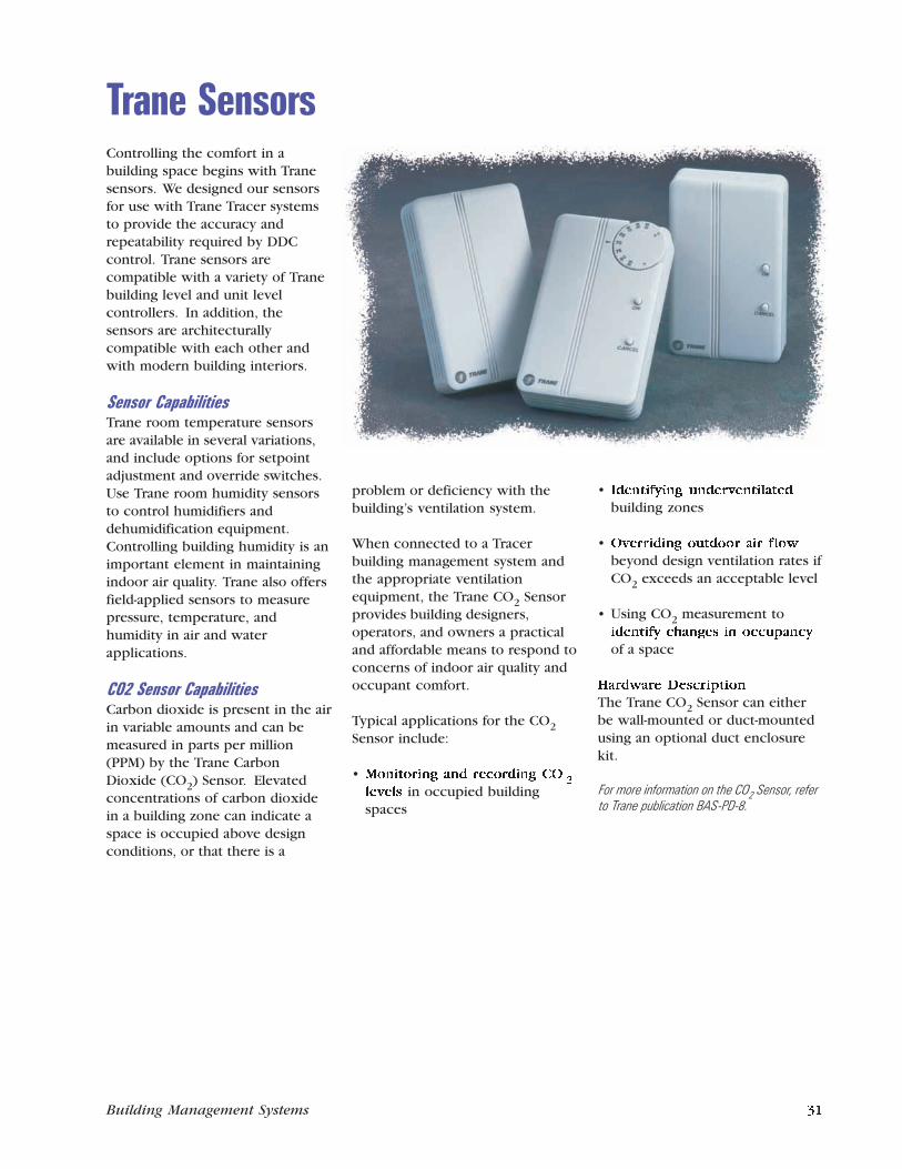
Trane Building Management SystemsThe Trane Company’s line ofbuilding management systemsincludes a product for everycontrol need, from a remedy for aproblem area in an existingbuilding to a comprehensivesystem for a major complex orcampus. Trane buildingmanagement system capabilitiesand features include:
• Scheduling for weekdays andholidays
• After-hours usage tracking
• Management reports and logs
• Dynamic and interactive colorgraphics
• Direct digital control and customprogramming routines
• Comfort monitoring by zone
• Energy-saving software includingchiller plant control, demandlimiting, optimal start/stop, andnight setback
• Operator interface that is easy tolearn and use
• Architecturally-compatible,ergonomic design
Trane is unique in its ability to offertotal Integrated Comfort systems,HVAC, controls, and buildingmanagement from a single source.These systems constitute avigorous response to today’sdemands from regulatory agencies,building designers, contractors,owners, and occupants.
Pages two through nine in thiscatalog illustrate four typical Tranebuilding management systemapplications. They demonstrate theversatility and integrationcapabilities of the various productsin this catalog. Each Trane buildingmanagement installation isdesigned specifically for the facilityit manages and may be configureddifferently than the examplesshown.
Standalone Building ControlSystems
• Applied commercial
• Unitary
Building Size
• Mid-size to large
Features
• Time of day schedulingincluding optimum start/stopand night purge
• Demand limiting
• Timed override
• Reports and trends
• Remote communications
• Custom programming routines
• Chiller sequencing
• Year 2000 compliant
• Manufactured in an ISO 9001certified facility
Benefits
• Comprehensive set of reports totrack and analyze data
• Reduced energy costs withstandard, tested energymanagement applications
• Flexibility to provide after-hourscomfort through timed override
• Quick identification of operatingproblems using equipmentdiagnostics
• Easy-to-use, dynamic colorgraphics (optional)
For more information about See page
IntelliPak Rooftop Unit .............................................................. 30
Room Temperature Sensor ......................................................... 31
Tracer 100i ................................................................................. 18
Variable Air Volume Command Unit .......................................... 30
VariTrane Variable Air Volume Terminal Unit ............................. 29
Trane SensorsControlling the comfort in abuilding space begins with Tranesensors. We designed our sensorsfor use with Trane Tracer systemsto provide the accuracy andrepeatability required by DDCcontrol. Trane sensors arecompatible with a variety of Tranebuilding level and unit levelcontrollers. In addition, thesensors are architecturallycompatible with each other andwith modern building interiors.
Sensor CapabilitiesTrane room temperature sensorsare available in several variations,and include options for setpointadjustment and override switches.Use Trane room humidity sensorsto control humidifiers anddehumidification equipment.Controlling building humidity is animportant element in maintainingindoor air quality. Trane also offersfield-applied sensors to measurepressure, temperature, andhumidity in air and waterapplications.
CO2 Sensor CapabilitiesCarbon dioxide is present in the airin variable amounts and can bemeasured in parts per million(PPM) by the Trane CarbonDioxide (CO2) Sensor. Elevatedconcentrations of carbon dioxidein a building zone can indicate aspace is occupied above designconditions, or that there is a
problem or deficiency with thebuilding’s ventilation system.
When connected to a Tracerbuilding management system andthe appropriate ventilationequipment, the Trane CO2 Sensorprovides building designers,operators, and owners a practicaland affordable means to respond toconcerns of indoor air quality andoccupant comfort.
Typical applications for the CO2Sensor include:
• Monitoring and recording CO2
levels in occupied buildingspaces
• Identifying underventilated
building zones
• Overriding outdoor air flow
beyond design ventilation rates ifCO2 exceeds an acceptable level
• Using CO2 measurement toidentify changes in occupancy
of a space
Hardware Description
The Trane CO2 Sensor can eitherbe wall-mounted or duct-mountedusing an optional duct enclosurekit.
For more information on the CO2 Sensor, referto Trane publication BAS-PD-8.
2 Building Management Systems Building Management Systems 31

© American Standard Inc. 1999. All rights reserved.
Cover illustration: Frank Miller Studios, Inc.
Published by the Trane Building Automation Systems, St. Paul, Minnesota. Printed in the USA.
Integrated Comfort, Tracer 100i, and Voyager are trademarks of The Trane Company. CenTraVac, Series RCenTraVac, IntelliPak, Climate Changer, Series R, 3-D, Tracer, Tracer Summit, Tracker, Trane, VariTrac, andVariTrane are registered trademarks of The Trane Company.
The following are trademarks or registered trademarks of their respective companies: ARCNET fromDatapoint Corporation, AutoCAD from Autodesk, Inc., BACnet from ASHRAE, Pentium from IntelCorporation, 3Com/U.S. Robotics Sportster from 3Com, and Windows and Internet Explorer from MicrosoftCorporation.

ContentsTrane Building Management Systems
Standalone Building Control .......................................... 2Networked Building Control ......................................... 4Chiller Plant (Subsystem) Management ........................ 6Simple Building Control ................................................. 8
ICS ArchitectureOperator Interface .......................................................... 12Building Control ............................................................. 12Unit Control .................................................................... 12
Operator InterfaceTracer Summit PC Workstation ...................................... 13Building Management Network ..................................... 16
Building ControlTracer Summit Building Control Unit ............................ 17Tracer 100 Series Systems: Tracer L, CPM, and 100i ...... 18Tracker and VariTrac Zoning System ............................. 20Simple Zoning Control ................................................... 21
General-Purpose Unit ControlThermostat Control Module .......................................... 23Programmable Control Module ..................................... 24Universal Programmable Control Module ..................... 24
Application-Specific Unit ControlTerminal Unit Controller ................................................ 26Lighting Control Panel ................................................... 27DDC Chiller Sequencer .................................................. 28
Factory-Mounted Unit ControlChillers ............................................................................ 29VariTrane VAV Terminal Units ......................................... 29Commercial Self Contained Units ................................. 29IntelliPak Rooftop Units ................................................. 30Voyager Rooftop Units ................................................... 30Air Handlers .................................................................... 30Terminal Unit Controllers .............................................. 30VariTrac Changeover-Bypass Zoning System ................. 30VAV Command Unit ....................................................... 30
Trane SensorsSensors ............................................................................ 31
Building Management Systems 1

Building Management Systems
The Trane CompanyWorldwide Applied Systems Group3600 Pammel Creek RoadLa Crosse, WI 54601-7599
www.trane.com© American Standard Inc. 1999
BAS-DS-1Supersedes BAS-DS-1-796
File No. PL-ES-BAS-000-DS-1-0499
Printed on recycled paper.
The Trane Company has a policy ofcontinuous product improvement andreserves the right to change designand specification without notice.