Embed Size (px)
Citation preview

GRAUPNER GmbH & Co. KG D-73230 KIRCHHEIM/TECK GERMA NY Modifications reserved. No liability for printing errors. Id.-Nr. 0062273 3/2011 - 1 -
Order No. 4239
BUILDING INSTRUCTIONS
ELEKTRO-ROOKIE QR
RC electric-powered model for three LiPo cells of a round 2500 mAh
This model requires a 3-function or 4-function HoTT radio control system

GRAUPNER GmbH & Co. KG D-73230 KIRCHHEIM/TECK GERMA NY Modifications reserved. No liability for printing errors. Id.-Nr. 0062273 3/2011 - 2 -
Please be sure to read through the Safety Notes in the Appendix to these operating instructions. If you ever dispose of the model, it is important to pass on the complete building instructions to the new owner.
Introduction The ELEKTRO-ROOKIE QR is an RC model aircraft designed expressly for the newcomer to model flying, and offers a superb performance in the air. Either the rudder or the ailerons can be set up as the primary directional control. If you intend only to fit rudder control at first, it is nevertheless an easy job to fit working ailerons at a later stage. For safety reasons the model’s all-up weight should not exceed 850 g.
RC system accessories (not included) GRAUPNER MX-12 HoTT 2.4 COMPUTER SYSTEM Order No. 4754 ULTRAMAT 16S battery charger Order No. 6468 C231 servo (two to four required) Order No. 5109.LOSE Servo extension lead, 100 mm (two required) Order No. 3935.11 Servo extension lead, 320 mm (two required) Order No. 3935.32 LiPo battery, 20C 3/2500, 11.1 V, G3.5 Order No. 7633.3
Essential tools and adhesives (not included) Balsa knife Order No. 980 Cyano-acrylate (“cyano”) Order No. 5821 Cyano-acrylate activator (“kicker”) Order No. 953.150 You will also need the following items: cross-point screwdriver, flat-nose pliers, paper scissors, 1.5 mm A/F allen key, adhesive tape, paper towel, protective gloves, goggles.
Building instructions Please start by reading right through these building instructions, so that you gain an overall understanding of how the model goes together. Lay out the components required for each stage of construction, together with the tools and adhesives. When working on the model always keep the bench surface clean and smooth, or cover it with a sheet of soft foam; this avoids damage to the model’s surfaces. Unless stated otherwise, use cyano-acrylate glue (“cyano”) and activator (“kicker”) for all joints on this model: the best method is to apply adhesive to one side of the joint, and spray activator on the mating surface. Please take particular care to avoid adhesive getting on your hands or the surface of the model: wipe off excess glue immediately using kitchen paper (paper towel). Caution: cyano-acrylate adhesives must not be allow ed to come into contact with any part of your body, and especially not your eyes. For this reason we recommend that you wear goggles when building the m odel. Store all glues well out of the reach of children. For safety reaso ns use the adhesive stated above exclusively. Please take the time to read through the operating instructions for the BRUSHLESS CONTROL 18 speed controller, which is sup plied in the motor set.
GRAUPNER GmbH & Co. KG D-73230 KIRCHHEIM/TECK GERMA NY Modifications reserved. No liability for printing errors. Id.-Nr. 0062273 3/2011 - 3 -
Fuselage and fin You will find a strip of foam linking the bottom edge of the rudder to the fuselage; cut this away, and move the rudder repeatedly from side to side to free up the integral hinge line.
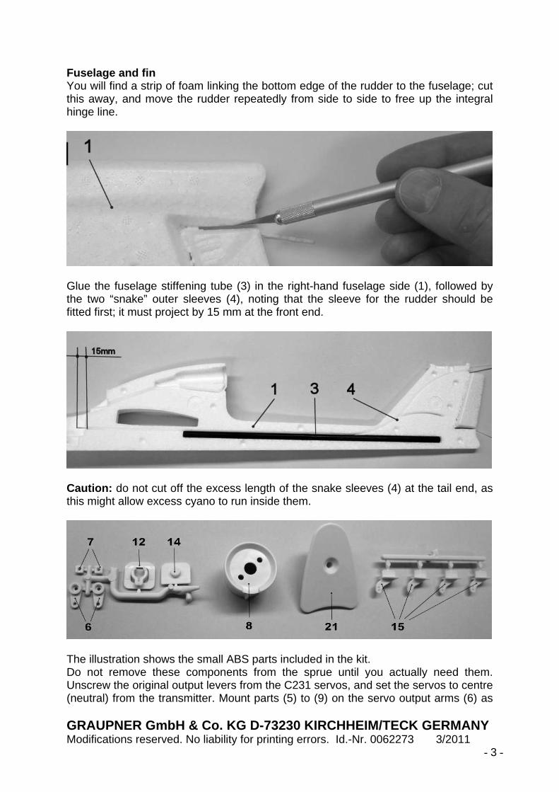
Glue the fuselage stiffening tube (3) in the right-hand fuselage side (1), followed by the two “snake” outer sleeves (4), noting that the sleeve for the rudder should be fitted first; it must project by 15 mm at the front end.
Caution: do not cut off the excess length of the snake sleeves (4) at the tail end, as this might allow excess cyano to run inside them.
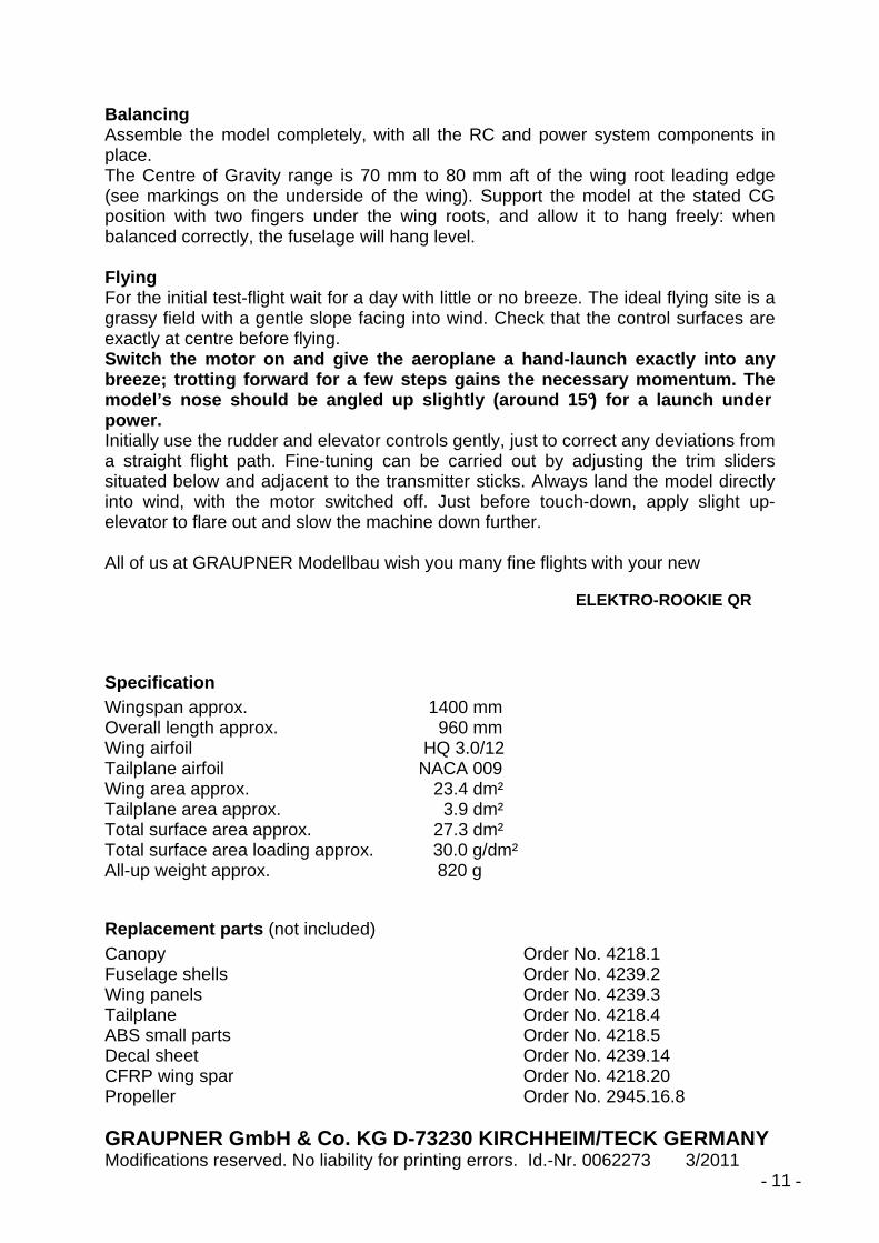
The illustration shows the small ABS parts included in the kit. Do not remove these components from the sprue until you actually need them. Unscrew the original output levers from the C231 servos, and set the servos to centre (neutral) from the transmitter. Mount parts (5) to (9) on the servo output arms (6) as

GRAUPNER GmbH & Co. KG D-73230 KIRCHHEIM/TECK GERMA NY Modifications reserved. No liability for printing errors. Id.-Nr. 0062273 3/2011 - 4 -
shown in the photo. Tighten the nuts just to the point where the swivel pushrod connectors rotate smoothly, but without lost motion.
Screw the servo output arms to the servos in the arrangement shown in the picture.
Fix the rudder servo in the right-hand fuselage shell (1) with a single drop of cyano on each mounting lug and one on the underside of the servo case. Caution: do not use thin cyano to secure the servos , or too much cyano of any type, as it could penetrate the case and jam the mo ving parts. Use the same procedure to glue the elevator servo in the left-hand fuselage shell (2). Check from the transmitter that both servos still work correctly. Fix the motor (10) to the motor mount (8) using the two screws (9). Tighten the screws fully, and secure each one with a drop of cyano.
The motor mount (8) can now be glued in the right-hand fuselage shell. Press the cables into the channel, and secure them with a little glue. If necessary, shorten the motor cables by deploying them in a curve - as shown in the photo - so that the BRUSHLESS CONTROL 18 speed controller lies flat on the fuselage. Tack the speed controller in place with a little adhesive.

GRAUPNER GmbH & Co. KG D-73230 KIRCHHEIM/TECK GERMA NY Modifications reserved. No liability for printing errors. Id.-Nr. 0062273 3/2011 - 5 -
Connect the power system - but without fitting the propeller - and check that it functions properly, referring to the instructions supplied with the power set.
Fit the countersunk plastic screw (22) in the threaded insert (11), then glue the insert in the top of the fin as shown, again using cyano. Remove the plastic screw. The fuselage shells (1) and (2) are now ready for joining. To be on the safe side, repeat the check of the servos and the motor (without propeller), and temporarily fit the pushrods (16) and (18) in the outer sleeves to ensure that they slide smoothly. The photo below shows the fuselage shells (1) and (2) ready for joining.
The first step in joining the shells is to offer them up “dry” (no glue). It is a good idea to secure the loose cables temporarily with tape to avoid them getting caught in the joint.

GRAUPNER GmbH & Co. KG D-73230 KIRCHHEIM/TECK GERMA NY Modifications reserved. No liability for printing errors. Id.-Nr. 0062273 3/2011 - 6 -
Caution: the next procedure demands your full conce ntration. Take great care to avoid glue getting onto the area of the rudder h inge. Keep some absorbent kitchen paper to hand so that you can wipe away exc ess cyano immediately. Tip: if you are not an experienced model builder, avoid using activator spray for this procedure. Instead tape the fuselage shells together and leave the assembly while the glue sets hard; this may take several hours. The canopy Glue the canopy retainer clip (12) in the fuselage as shown, and glue the mating spigot (14) in the canopy (13).
Allow the glue to harden fully before fitting the canopy on the fuselage. Tip: if the retainer clip (12) grips too strongly for comfort, bend the two claws outwards, working gently and evenly. The tailplane Cut away the unwanted foam at both ends of the elevator, and move the control surface repeatedly in both directions to free up the integral hinge. This procedure should also be carried out with the wing-mounted ailerons. Glue the spreader plate (21) to the top of the tailplane as shown, and glue the horn (15) in the slot in the underside of the elevator.

GRAUPNER GmbH & Co. KG D-73230 KIRCHHEIM/TECK GERMA NY Modifications reserved. No liability for printing errors. Id.-Nr. 0062273 3/2011 - 7 -
The control surface linkages Cut off the excess length of the snake outer sleeves (4) at the tail end of the fuselage. Slip the rudder pushrod (16) into the outer sleeve from the tail end, and slip the front end through the swivel pushrod connector (5) mounted on the right-hand servo. Connect the rudder horn (15) to the pre-formed end of the pushrod, then glue the horn in the slot in the rudder. Install the elevator pushrod (18) in the same way.
Place the tailplane (20) on the fin and secure it with the countersunk plastic screw (22). Tip: if you are a beginner to model flying, connect the pushrods to the outer holes in the rudder and elevator horns in order to obtain small control surface travels. If you prefer more marked control response, use the inner holes in the horns, as shown in the photographs.
Set the rudder and elevator to centre, then tighten the clamping screws (9). Hold the connector barrel tightly in a pair of flat-nose pliers while you do this, as shown in the photograph.
The wing Glue the spar channel covers (24) and (26) in the wing panels as shown, but do not use activator spray for these joints. Spray cyano activator in the channel for the spar (27) to eliminate any possibility that it might become stuck permanently in the wing. If you do not intend to equip the model with aileron servos initially, apply adhesive film (33) over the aileron servo openings and the aileron hinge line. Please note that the following parts are not required for the rudder / elevator version: four servo extension leads, two aileron pushrods (31), two aileron horns (15), and two C 231 servos. Please refer to the section entitled “Control surface checks ” for information on control surface travels.

GRAUPNER GmbH & Co. KG D-73230 KIRCHHEIM/TECK GERMA NY Modifications reserved. No liability for printing errors. Id.-Nr. 0062273 3/2011 - 8 -
The picture shows the version of the wing without aileron servos.
Fit 14 mm long output arms (supplied with the servos) on the aileron servos. Set the servos to centre from the transmitter, press them into the servo wells, and press the servo leads in the channels. Check that the servos work properly before securing them with a drop of glue on each mounting lug.
Installing the receiving system

GRAUPNER GmbH & Co. KG D-73230 KIRCHHEIM/TECK GERMA NY Modifications reserved. No liability for printing errors. Id.-Nr. 0062273 3/2011 - 9 -
The illustration shows the HoTT receiver installed above the rudder servo using Velcro tape (32). Route the receiver aerials through the fuselage opening above the speed controller. We recommend the following receiver channel assignment: Connect the speed controller to receiver socket I, the left aileron servo to socket II, the elevator servo to socket III, the rudder to socket IV, the right-hand aileron servo to socket V. Coil up the servo leads next to the receiver, so that they cannot obstruct the servo output arms when they move. Connect the 100 mm servo extension leads to sockets II and V. Note: if the model is fitted with rudder and elevator controls only, the rudder servo should be connected to socket II. The receiving system is switched on by connecting the G3.5 plugs and sockets, as shown in the photo. Bind the receiver to the transmitter using the procedure outlined in the manual supplied with your RC system. Check the direction of motor rotation: if the propeller spins clockwise when viewed from the tail, disconnect the push-button (bottom of picture) from the speed controller. Installing the wing Push the right-hand wing panel into the side of the fuselage, then slide the CFRP spar into place, followed by the left-hand wing panel. Tip: squeeze together the pro-jecting lugs at the root of the left-hand wing panel, as this makes it easier to engage the wing retainer system.
Slip the servo leads through the appropriate channel in the left-hand fuselage side (2) as shown in the picture; this is easier if you use a pair of tweezers or small pliers. Checking the control surfaces The stick mode at the transmitter should be set as shown in the photograph: throttle (motor speed) and direction (aileron) on the right-hand stick. Stick back (towards you) equates to motor off; stick forward means full power. Elevator control should be on the left-hand stick: pulling the stick back deflects the elevator up; pushing it away from you produces down-elevator. The rudder is operated by moving the left-hand stick left and right. If any function works the wrong way round, use your transmitter’s servo reverse facility to correct that channel. If you want maximum possible control surface travels, connect the pushrods to the innermost holes in the control surface horns (15). If you are a relative beginner to model flying, we recommend that you connect the pushrods to the outer holes.

GRAUPNER GmbH & Co. KG D-73230 KIRCHHEIM/TECK GERMA NY Modifications reserved. No liability for printing errors. Id.-Nr. 0062273 3/2011 - 10 -
Fitting the propeller Install the propeller on the motor as shown in the photo, using a 1.5 mm Ø steel rod to tighten the spinner. Caution: fit the propeller with the lettering facing forward, i.e. towards the model’s nose. If you fit it the other way round, motor power will be greatly reduced.
Decals It is not necessary to paint the model’s SOLIDPOR® components. If you wish to give the aircraft a coloured finish, we recommend the use of GRAUPNER LEXACOLOR spray paints, Order No. 945... Do not rub down the surfaces prior to painting; instead wipe them with cellulose thinners, Order No. 1409, and a piece of absorbent paper towel. Cut out and apply the decals from the decal sheet (28) to complete the model.
GRAUPNER GmbH & Co. KG D-73230 KIRCHHEIM/TECK GERMA NY Modifications reserved. No liability for printing errors. Id.-Nr. 0062273 3/2011 - 11 -
Balancing Assemble the model completely, with all the RC and power system components in place. The Centre of Gravity range is 70 mm to 80 mm aft of the wing root leading edge (see markings on the underside of the wing). Support the model at the stated CG position with two fingers under the wing roots, and allow it to hang freely: when balanced correctly, the fuselage will hang level. Flying For the initial test-flight wait for a day with little or no breeze. The ideal flying site is a grassy field with a gentle slope facing into wind. Check that the control surfaces are exactly at centre before flying. Switch the motor on and give the aeroplane a hand-l aunch exactly into any breeze; trotting forward for a few steps gains the necessary momentum. The model’s nose should be angled up slightly (around 1 5°) for a launch under power. Initially use the rudder and elevator controls gently, just to correct any deviations from a straight flight path. Fine-tuning can be carried out by adjusting the trim sliders situated below and adjacent to the transmitter sticks. Always land the model directly into wind, with the motor switched off. Just before touch-down, apply slight up-elevator to flare out and slow the machine down further. All of us at GRAUPNER Modellbau wish you many fine flights with your new
ELEKTRO-ROOKIE QR
Specification Wingspan approx. 1400 mm Overall length approx. 960 mm Wing airfoil HQ 3.0/12 Tailplane airfoil NACA 009 Wing area approx. 23.4 dm² Tailplane area approx. 3.9 dm² Total surface area approx. 27.3 dm² Total surface area loading approx. 30.0 g/dm² All-up weight approx. 820 g
Replacement parts (not included) Canopy Order No. 4218.1 Fuselage shells Order No. 4239.2 Wing panels Order No. 4239.3 Tailplane Order No. 4218.4 ABS small parts Order No. 4218.5 Decal sheet Order No. 4239.14 CFRP wing spar Order No. 4218.20 Propeller Order No. 2945.16.8

GRAUPNER GmbH & Co. KG D-73230 KIRCHHEIM/TECK GERMA NY Modifications reserved. No liability for printing errors. Id.-Nr. 0062273 3/2011 - 12 -
Parts List - ELEKTRO-ROOKIE QR Part No.
Description No. off
Material Dimensions, mm
1 R.H. fuselage shell 1 SOLIDPOR® Ready made 2 L.H. fuselage shell 1 SOLIDPOR® Ready made 3 Fuselage stiffening tube 1 CFRP 10 / 9 Ø x 450 4 Control “snake” outer sleeve 2 Nylon 1.9 Ø 5 Swivel pushrod connector 2 Steel M2, ready made 6 Servo output lever 2 ABS Ready made 7 Self-locking nut 2 ABS Ready made 8 Motor mount 1 ABS Ready made 9 Cheesehead screw 4 Steel M3 x 5 10 COMPACT 300 7.4 V power set 1 Steel / plastic Ready made 11 Threaded insert 1 Nylon M4, ready made 12 Canopy retainer clip 1 ABS Ready made 13 Canopy 1 SOLIDPOR® Ready made 14 Canopy retainer spigot 1 ABS Ready made 15 Control surface horn 4 ABS Ready made 16 Rudder pushrod 1 Steel 0.6 Ø x 708,
ready made 17 Spigot 1 ABS Ready made 18 Elevator pushrod 1 Steel 0.6 Ø x 774,
ready made 19 Rudder horn 1 ABS Ready made 20 Tailplane 1 SOLIDPOR® Ready made 21 Tailplane spreader plate 1 ABS Ready made 22 Countersunk screw 1 Nylon M4 x 25 23 L.H. wing panel 1 SOLIDPOR® Ready made 24 L.H. spar channel cover 1 SOLIDPOR® Ready made 25 R.H. wing panel 1 SOLIDPOR® Ready made 26 R.H. spar channel cover 1 SOLIDPOR® Ready made 27 CFRP wing spar 1 CFRP 10 / 8 Ø x 600 28 Decal 12 Self-adhesive film Sheet 29 Propeller 1 Plastic 160 x 80 30 Grubscrew 22 Steel M3 x 3 31 Aileron pushrod 2 Steel Ready made 32 Velcro tape 1+1 Plastic 33 x 25 x 3 33 Aileron servo / aileron gap cover L+R Adhesive film Oversize
Environmental Protection Notes The presence of this symbol on a product, in the user instructions or the packaging, means that you must not dispose of that item, in the ordinary domestic waste when the product comes to the end of its useful life. The correct method of disposal is to take it to your local collection point for recycling electrical and electronic equipment. Individual markings indicate which materials can be recycled and re-used. You can make an important contribution to the protection of our shared environment by re-using the product, recycling the basic materials or
re-processing redundant equipment in other ways. Dry cells and rechargeable batteries must be removed from the device and taken separately to a suitable battery disposal centre.

GRAUPNER GmbH & Co. KG D-73230 KIRCHHEIM/TECK GERMA NY Modifications reserved. No liability for printing errors. Id.-Nr. 0062273 3/2011 - 13 -
If you don’t know the location of your nearest disposal centre, please enquire at your local council office.
Safety Notes Before you fly the model for the first time it is essential (and a legal requirement) to take out an insurance policy designed to cover modelling risks. Be sure to read right through the instructions covering assembly and ope ration of your model before you attempt to operate it for the first time. You alone ar e responsible for the safe operation of your radio-controlled model aeroplane. Young people should onl y be permitted to build and fly this model under the instruction and supervision of an adult who is aware of the hazards involved in this activity. In legal terms our models are classed as aircraft, and as such are subject to statutory regulations and restrictions which must be observed. Our brochure “Model lflugrecht, Paragrafen und mehr” (Model Aviation Law, Legal Requirements and m ore) is available under Order No. 8034.02, and contains a summary of all these rules; your local model shop should have a copy which you can read. There are also Post Office regul ations concerning your radio control system, and these must always be observed. Refer to your RC system instructions for more details. It is important to use only those parts included in the kit, together with other genuine Graupner accessories and replacement parts as recommended expressly by us. Even if you change a single component, you can no longer be sure that the whole system w ill work reliably, and such changes also invalidate your guarantee. Avoid short circuits and reverse polarity at all times. The high energy density of rechargeable batteries involves a consta nt risk of fire and even explosion. A radio-controlled model aircraft can only work properly and fulfi l your expectations if it is built very carefully, and in accordance with the building instructions. If you wish to avoid injuring people and damaging property, it is essential to be cautious and pai nstaking at all stages of building and operating your model. Nobody would climb into a full-size sai lplane and try to fly it without first completing a course of training. Model flying i s just such a skill, and has to be learned in exactly the same way. However, as manufacturers we have no means of influencing the w ay you build and operate your RC model aircraft, and for this reason we can do no more tha n point out the hazards expressly. We accept no further liability. If you need help, please enlist the aid of an experienced modell er, join a model club or enrol at a model flying training school. Model shops and the specialist model press are also good sources of information. The best course is always to join a club and fly at the approved model flying site. Adhesives and paints contain solvents which may be hazardous to heal th under certain circumstances. Always read and observe the notes and warnings suppli ed by the manufacturer of these materials. The operator of the model must be in full possession of his or her bodily and mental faculties. As with car driving, flying a model aircraft under the influence of alcohol or drugs is highly dangerous and not permissible under any circumstances. Make sure that all passers-by and onlookers are aware of the hazards involved in the operation of your model. Remind spectators to keep a safe distance from the model. Always maintain a safe distance between your model and other people or objects. Never fly low over people or directly towards them. Radio-controlled models should only be flown in “normal” weather condi tions, i.e. a temperature range of -5° to +35°C. More extreme temperatures can lead to changes in battery capacity, material characteristics, the strength of glued joi nts and other unwanted effects.

GRAUPNER GmbH & Co. KG D-73230 KIRCHHEIM/TECK GERMA NY Modifications reserved. No liability for printing errors. Id.-Nr. 0062273 3/2011 - 14 -
All model flyers should behave in a way which minimises the dang er to people and property. Never act in any manner which will disturb other pilots, or hav e an adverse effect on safe, orderly flying at the site. Don’t operate your model aeroplane in the vicinity of overhead power cables, industrial sites, residential areas, public roads, school playgrounds or sports fiel ds etc.
Pre-flight checks Check that the radio control system works correctly and at f ull range before every flight: switch on the transmitter and the receiving system, fit the transmi tter aerial and extend it to its full length; walk away from the model, and check that all the contr ol surfaces work smoothly and immediately at an appropriate distance; check also that they deflect in the correct “sense” in relation to the stick movements. Repeat the check with the motor running, while a friend holds the model securely for you. If you are a relative beginner to this type of model flying, we r ecommend that you enlist an experienced model pilot to help you check and test-fly the model. Please don’t ignore our warnings. They refer to hazardous materials and processes which, if ignored, can result in fatal injury or serious damage to property. Propellers powered by a motor constitute a permanent hazard a nd represent a real risk of injury. Don’t touch them with any part of your body. For example, a propeller spinning at high speed can easily cut your finger badly. Keep well clear of the rotational plane of the propeller. You never know when some part may come loose and fly off at high speed, hitting you or anybody else in the vicinity. In unfavourable circumstances this could result in serious injury. Ensur e that the revolving propeller never comes into contact with any object. Make sure that it is impossible for any object to stall or bl ock the propeller. Every time you intend to operate your model, check carefully that it and everything attached to it (e.g. propeller, RC components etc.) is in good condition and undamage d. If you find a fault, do not fly the model until you have corrected it. Satisfy yourself that your frequency is unoccupied before you switc h on. Radio interference caused by unknown sources can occur at any time without warning. If this should happen, your model will be uncontrollable and completely unpredictable. Nev er leave your radio control system unguarded, as other people might pick it up and try to use it. Do not switch the electric motor on unless you have checked that t here is nothing in the rotational plane of the propeller. Never attempt to stop the pr opeller when it is spinning. Electric motors with propellers fitted must only be run when fi rmly mounted. If you are to fly your model safely and avoid problems, it is e ssential that you are aware of its position and attitude throughout each flight - so don’t let it fly t oo far away. If you detect a control problem or interference during a flight, immediately land the model to prevent a potential accident. Model aeroplanes must always give way to f ull-size aircraft. Take-off and landing strips should be kept free of people and other obstacles. Your RC system can only work reliably if the batteries are kept fully charged. Never use hot, faulty or damaged batteries. It is important to observe the instructions supplied by the battery manufacturer. Before every flight ensure that all functions are working correc tly, and carry out a range check. Always ensure that the throttle stick (or other throttle cont rol) is at the motor OFF position before switching the transmitter on. To avoid the electric motor bursting into life unexpectedly, always switch the transmitter on first, followed by the r eceiving system. When switching off, reverse the order: receiving system first, then the transmit ter.

GRAUPNER GmbH & Co. KG D-73230 KIRCHHEIM/TECK GERMA NY Modifications reserved. No liability for printing errors. Id.-Nr. 0062273 3/2011 - 15 -
Check that the control surfaces work in the correct “sense”, i.e. that they deflect in the direction which corresponds to the movement of the stick. After each session remove all the batteries from the model and store them in a discharged state at a temperature of about +5° to +25°C. They must be k ept out of the reach of children. Please don’t misunderstand the purpose of these notes. We only want to make you aware of the many dangers and hazards which can arise if you lack knowl edge and experience, or work carelessly or irresponsibly. Provided that you take reasonabl e care, model flying is a highly creative, instructive, enjoyable and relaxing pastime. Manufacturer’s declaration: If material defects or manufacturing faults should arise in a product distributed by us in the Federal Republic of Germany and purchased by a consumer (§ 13 BGB ), we, Graupner GmbH & Co. KG, D-73230 Kirchheim/Teck, Germany, acknowledge the obl igation to correct those defects within the limitations described below. The consumer is not entitled to exploit this manufacturer’s decla ration if the failure in the usability of the product is due to natural wear, use under competiti on conditions, incompetent or improper use (including incorrect installation) or external influe nces. This manufacturer’s declaration does not affect the consumer’s lega l or contractual rights regarding defects arising from the purchase contract between th e consumer and the vendor (dealer). Extent of the guarantee If a claim is made under guarantee, we undertake at our discre tion to repair or replace the defective goods. We will not consider supplementary claims, es pecially for reimbursement of costs relating to the defect (e.g. installation / removal cost s) and compensation for consequent damages unless they are allowed by statute. This does not af fect claims based on legal regulations, especially according to product liability law. Guarantee requirements The purchaser is required to make the guarantee claim in writing, a nd must enclose original proof of purchase (e.g. invoice, receipt, delivery note) and this guarantee card. The purchaser must send the defective goods to us at his own cost, using the addr ess stated above. The purchaser should state the material defect or manufacturing fa ult, or the symptoms of the fault, in as accurate a manner as possible, so that we can c heck if our guarantee obligation is applicable. The goods are transported from the consumer to us and from us to the co nsumer at the risk of the consumer. Duration of validity This declaration only applies to claims made to us during the claim period as stated in this declaration. The claim period is 24 months from the date of purcha se of the product by the consumer from a dealer in the Federal Republic of Germany (purchas e date). If a defect arises after the end of the claim period, or if the evidence or docum ents required according to this declaration in order to make the claim valid are not presented u ntil after this period, then the consumer forfeits any rights or claims from this declarati on. Limitation by lapse of time If we do not acknowledge the validity of a claim based on thi s declaration within the claim period, all claims based on this declaration are barred by the s tatute of limitations after six months from the time of implementation; however, this cannot occur before the end of the claim period. Applicable law This declaration, and the claims, rights and obligations arising from it, are based exclusively on the pertinent German Law, excluding the norms of international private law, and excluding UN retail law.