Embed Size (px)
Citation preview
Version 1 – December 2014
Building Information Modeling (BIM) Standard & Guide
No portion of this work may be reproduced without the express written permission
of the copyright holders. All rights reserved by Florida International University.
` FIU BIM Specification ‐ Final 120814
1
Table of Contents INTRODUCTION ............................................................................................................................................. 4
Intent: ........................................................................................................................................................ 4
BIM Goals: ................................................................................................................................................. 4
BIM Uses: .................................................................................................................................................. 5
Capital planning support: ...................................................................................................................... 6
Pre‐Design and Programming ............................................................................................................... 6
Site Conditions ‐ Existing Conditions and New Construction ............................................................... 6
Architectural Model ‐ Spatial and Material Design Models .................................................................. 7
Space and Program Validation .............................................................................................................. 7
Design Visualization .............................................................................................................................. 7
System Models ‐ Structural, MEPF and Civil design .............................................................................. 8
Leadership in Energy and Environmental Design (LEED) Analysis ........................................................ 8
Spatial Coordination & Constructability Review ................................................................................... 8
4D Scheduling and Sequencing ............................................................................................................. 9
5D Estimation ........................................................................................................................................ 9
Design for Maintenance (D4M) Review .............................................................................................. 10
Shop Drawings, Sleeve Drawings and Fabrication .............................................................................. 10
BIM in the field for Installation ........................................................................................................... 10
REQUIREMENTS .......................................................................................................................................... 10
General Overview of Deliverables .............................................................................................................. 11
Two dimensional (2D) documents .......................................................................................................... 12
Ownership & Reuse: ............................................................................................................................... 12
BIM Execution Plan ................................................................................................................................. 13
Model Progression Schedule .................................................................................................................. 13
LOD vs. Level of Detail ............................................................................................................................. 14
LOD Definition ......................................................................................................................................... 14
Model Accuracy & Tolerances: ............................................................................................................... 15
General Information ................................................................................................................................... 15
Software .................................................................................................................................................. 16
Versions ................................................................................................................................................... 17
` FIU BIM Specification ‐ Final 120814
2
Geo ‐ Reference ...................................................................................................................................... 17
Project North ........................................................................................................................................... 17
File Sharing Platform ............................................................................................................................... 17
File Structure & Naming .......................................................................................................................... 17
Sheet Sizes and Naming Conventions ................................................................................................. 18
Units and Tolerances........................................................................................................................... 18
Compensation ............................................................................................................................................. 18
BIM Roles & Responsibilities ....................................................................................................................... 19
Owners Role & Responsibility ................................................................................................................. 19
Design Team Roles & Responsibility ....................................................................................................... 19
Construction Team Roles & Responsibility ............................................................................................. 21
Process and BIM Workflows ....................................................................................................................... 22
General Requirement .............................................................................................................................. 22
Existing Conditions .............................................................................................................................. 22
Topographic and Property Line Surveying .......................................................................................... 22
Model Information Requests (MIR) / Request for Information (RFI) ................................................. 22
Change Orders .................................................................................................................................... 23
Spatial Coordination & Constructability Requirements ...................................................................... 23
BIM Use Matrix Minimum Requirements ........................................................................................... 25
Progress of Models & Review ............................................................................................................. 25
Planning Stage Requirements ................................................................................................................. 26
Area Calculations ................................................................................................................................ 27
Program Deliverables .......................................................................................................................... 27
Design Stage Requirements .................................................................................................................... 27
Model Content Requirements ............................................................................................................ 27
Design Deliverables ............................................................................................................................. 31
Bidding Phase .......................................................................................................................................... 32
Contractor Bidding .............................................................................................................................. 32
Construction Phase Requirements ......................................................................................................... 32
General ................................................................................................................................................ 32
Model Sharing ..................................................................................................................................... 32
Model Content Requirements ............................................................................................................ 32
Construction Deliverable .................................................................................................................... 35
` FIU BIM Specification ‐ Final 120814
3
Pay Application Verification ................................................................................................................ 36
As‐Built Model ......................................................................................................................................... 36
Design Team Responsibilities .............................................................................................................. 36
Construction Team Responsibilities .................................................................................................... 36
Archiving of Models .................................................................................................................................... 37
Information Exchanges ............................................................................................................................... 37
Construction Operations Building Information Exchange (COBie) Workflow, Roles and Responsibilities
and Deliverables ...................................................................................................................................... 37
A. List of Assets requiring COBie Data Set ........................................................................................... 38
B. Roles & Responsibilities .................................................................................................................. 38
C. COBie tabs required FIU: ................................................................................................................. 40
D. Classification tables ......................................................................................................................... 40
E. COBie Standard and FIU specified data set ..................................................................................... 41
F. Best Practices .................................................................................................................................. 41
G. COBie Progression Schedule (CPS) .................................................................................................. 43
Appendix: .................................................................................................................................................... 47
Sample BIMPxP and JBIMPxP .................................................................................................................. 47
Model Progression Schedule .................................................................................................................. 58
Deliverable Summary .............................................................................................................................. 63
Glossary ....................................................................................................................................................... 65
Acknowledgements ..................................................................................................................................... 68
References Used: ........................................................................................................................................ 68

` FIU BIM Specification ‐ Final 120814
4
INTRODUCTION In promoting the use of Building Information Modeling (BIM) 3D technology, Florida International University (FIU) has created this BIM Standard to define the Design and Construction BIM scope of work and the university’s operational intent for data usage when using BIM on new FIU Construction projects, major renovations and other projects. It is the University’s hope that by creating this Standard, they will continue to encourage further industry adoption of building information modeling both on the professional and academic level, and to allow the University’s Facility Management Department to achieve cost savings from BIM by making it easier for management personnel and future design and construction teams to access information about the buildings from the technology. BIM will be used as a tool to improve quality, cost and schedule by assisting in the coordination of trades, reducing field conflicts and improving the overall design and construction process. In creating this Standard, the University, its Consultants and local market BIM experts explored options in the implementation of building information modeling to determine optimum practical strategy. This Standard is a reflection of the teams work and will be reviewed periodically to ensure that it is reflected of current best practices. This Guide will be incorporated by reference into FIU design and construction project contracts and
annual contracts.
Intent: It is FIU’s intent to use BIM on all design and construction projects in the future and to reuse design and
construction BIMs and data for facility lifecycle management, capital planning, future alterations,
additions and renovations. To achieve this end, the BIMs must be structured to achieve this desired
purpose and the FIU BIM Standard will require that all design and construction deliverables for the
projects be created and derived from building information models.
BIM Goals: To maximize the value of BIM for the University;
BIM as an initial planning and program validation tool;
BIM as a visualization tool for campus master planning;
BIM as a visualization, coordination and communication tool during design, construction
and facility operations;
BIM as a resource for the design and construction of future alterations to buildings;
BIM for constructability and maintainability review to minimize change orders;
BIM for collecting and exchanging facility data through the use of an open standard, the
Construction Operations Building information exchange (COBie), from design through
construction to facility operations;
To use FIU BIMs as case studies for educational curriculum.
Additional goals and uses of BIM exist, and if so required, will be detailed in the RFP, RFQ, Contract
and /or BIM Project Execution plan (BIMPxP).
` FIU BIM Specification ‐ Final 120814
5
BIM Uses: Throughout the design, construction and operations process, various FIU departments and user groups
will be reviewing the BIMs and verifying that the model content is accurate and up to date and that FIU
BIM protocols are being followed. These stakeholders have various needs and uses for the BIMs.
The following is a list of FIU’s BIM Expectations by Department:
o Planning Department
The BIMs may be used for:
Space Planning & Visual 3D Analysis
Way finding
Feasibility studies
GIS data input management
Campus Master Planning
Evaluation of sites for new buildings
Design of spaces between buildings including circulation routes, utilities,
landscape and hardscape
Management of campus‐wide 3D information for utilities and civil engineering
infrastructure elements.
o FIU Construction Project Manager
The BIMs may be used for:
Pay application justification
Change Order clarification
Design for Maintenance Reviews
Clash Detection and Coordination
Construction staging and Phasing Plan Approval
Scheduling
o Facilities Management Operations Department
The BIMs may be used for:
Design for Maintenance Reviews
Preventative Maintenance
Corrective Maintenance
Scheduled Inspections
Asset Management
Inventory
Visualization
Schematic Diagram of Systems
IT Department
The BIMs may be used for:
Information Data Exchange from BIM to Maximo FIU’s Facilities Computerized
Maintenance Management System via COBie.
` FIU BIM Specification ‐ Final 120814
6
Security Camera Layout
Access Controls
o Academic Space Planning
The BIMs may be used for:
Area Calculations
Room Classifications
User Groups:
The BIMs may be used for:
Review of Program and space layout, access, design reviews.
BIM output can be utilized in a variety of ways to provide stakeholders with a greater understanding of
how a building is to be used, designed, constructed, maintained and adopted over time.
The various support activities in which BIM shall be utilized for FIU BIM projects shall be as follows:
Capital planning support: The model may be required to support owner planning activities for capital project development. The
model will be of sufficient development to assist the owner in reviewing renovation and systems
requirements for future projects. Planning review may include assessment of structural, mechanical,
electrical, and other systems, roofing fenestration and doors, circulation in and around the building,
underground utilities, as well as shading and views.
Pre‐Design and Programming For each campus FIU shall develop Programming Requirements which shall define space and adjacency
requirements to be adhered for individual projects. These requirements shall be based upon the
Education Plant Survey and Campus Master Plan. As‐Built Records of Existing Facilities shall be included
in this documentation and provided to project teams for their use during the Pre‐Design phase. Where
possible, all programming and as built data provided by FIU shall be expected to be incorporated in to
their design processes for reference and verification purposes.
Site Conditions ‐ Existing Conditions and New Construction For new construction and renovation projects, the modeling of the project site and the existing
structures, shall be included in the BIM requirements. Depending upon the project site, a model of the
site may be provided by FIU or by an external consultant using an approved IFC Compliant, 3D Site and
Utility Modeling BIM tool. Where no model exists, the Design Team must create one.
For all projects, the modeling of existing buildings shall be performed based upon provided as‐built
information, with field verification or electronic measurements conducted by Project team to validate
the level of accuracy.
For all existing conditions to be directly impacted, altered, or to be demolished by a proposed
renovation, Project Designers shall model those conditions to the appropriate level of detail that will
clearly demonstrate the design intent to building stakeholders, other Project Team Members, and
construction trades directly involved with executing this change.

` FIU BIM Specification ‐ Final 120814
7
Proposed site conditions shall reference campus benchmarks, and reference existing surveys. New site
and utility conditions shall be modeled in 3D, and shall coordinate system and spatial models three
dimensionally. Where other systems are directly impacted by landscape features (i.e. vegetation,
irrigation), those elements shall be modeled with correct size and clearance requirements in BIM.
Architectural Model ‐ Spatial and Material Design Models The Architectural Spatial model evolves during the design process, and the information modeled in BIM
shall be further refined as a project progresses toward construction. In the early phases of design, an
Architectural Model may be as simple as a massing model validating program requirements, basic
geometries, and building orientation to climate and site conditions.
As the design progresses, design options shall develop and need to be clearly documented and
delineated in the Model. Likewise, as materials and components are selected, generic assemblies shall
be assigned material properties, sizes, track LEED values, and other specific component information to
clearly define various building features such as walls, floors, roofs, doors and windows. Program space
requirements shall be modeled in the spatial model and validated using schedules and other validation
tools designated by the Department for the specific project.
Space and Program Validation The Design Team shall implement an iterative BIM‐enabled process to validate their adherence to the
Program in terms of Space and Equipment. That process can be established using the BIM authoring
software being used to produce the design, or it can be done using specialized Program Validation
software that utilizes the Design BIMs to validate adherence to the program. The Design Team shall
disclose the specifics of what software and format(s) will be used to perform Program Validation when
putting together the Design BIMPxP. Continued validation of the program and project requirements are
required as part of the BIM deliverable.
Design Visualization Design Visualization refers to animations, fly‐throughs, real‐time walk‐throughs, augmented reality,
static 3D renderings, 4D, and 3D Physical Models exported directly from a BIM Authoring Tools. The
BIMs shall be used to communicate the intent and workability of the proposed design solutions in
various ways and through various means to project stakeholders including FIU project managers, end
users, maintenance staff and financial stakeholders. For example, maintenance managers may review
maintenance clearances for air handlers in mechanical rooms and for VAV boxes above ceilings. FIU
encourages the Design & Construction Teams to find efficient and effective ways to communicate their
intent using BIM. At a minimum, the BIMs shall be used for design reviews, submittals, and construction
documents.
The Design and Construction Teams shall identify what specific means of visualization will be used for
design review and review submittals when putting together the BIMPxP. Those means may include, but
would not be limited to, the following:
Images (Screen Shots, Renderings)
Animations (Fly‐through, Panoramic immersion)
Federated BIMs in a Read‐only format. It is the Design & Construction Team’s
responsibility to make a free viewer available to the user.

` FIU BIM Specification ‐ Final 120814
8
Special consideration shall be given to security, safety and maintenance issues. At a minimum
visualization strategies shall be used to help analyze the following areas and needs:
Egress and other life safety related circulation
ADA Accessibility
Serviceability of equipment
Building Security (Access Control & Surveillance)
Daylight and artificial light levels
Crime Prevention through Environmental Design (CPTED)
It should be noted that even though the BIMs contain most of the source information needed for
visualization, they may require further refinement in specific animation and visualization software to
accomplish intended results.
System Models ‐ Structural, MEPF and Civil design With current technology, building systems are best organized as separate BIMs. Similar to the
Architectural models, the level of detail in these models shall evolve as design progresses such that
these systems are accurately modeled, and include sufficient performance, clearance, and LEED
requirements as part of the BIM. All underground utilities shall be 3D objects located at topographic
elevations, illustrating nominal sizes and type. The Owner may wish to integrate the BIMs into an energy
management system so models may be required to provide a level of development to support and
analyze electronic management systems or other monitoring and control systems.
Leadership in Energy and Environmental Design (LEED) Analysis Design Teams shall utilize energy modeling and sustainable design software that extracts BIM data in the
appropriate file format for the analysis tool to perform energy simulation and life cycle cost calculations
to validate their energy modeling. The Architectural model will be used as the basis of the analysis along
with associated material and building system information. Proper modeling techniques shall be used
with environmental parameters. The Design and Construction Teams shall disclose the specifics of what
software format(s) will be used to perform the Energy Validation Analysis when putting together the
BIMPxP. Energy simulation and life‐cycle cost calculations shall be based upon information extracted
directly from BIM technology and validated by energy modeling, whole building commissioning
requirements and LEED Certification when applicable. Utilization of the Model for lighting and acoustical
studies is encouraged.
Spatial Coordination & Constructability Review Spatial coordination means coordination between systems and components in the Design &
Construction BIMs appropriate to the design and construction phases. This process differs from Clash
Detection in that clashes may be deemed allowable by the Design Team depending on what systems are
conflicting. Clashes are not acceptable during Construction. The Design and Construction Teams shall
assure constructability by using a Federated Design BIM. A constructability review meeting where the
Design & Construction Teams invite FIU to participate is expected at least once during DD and CD phases
and throughout construction.
` FIU BIM Specification ‐ Final 120814
9
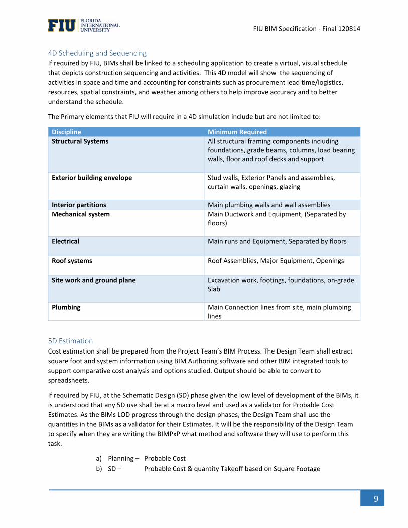
4D Scheduling and Sequencing If required by FIU, BIMs shall be linked to a scheduling application to create a virtual, visual schedule
that depicts construction sequencing and activities. This 4D model will show the sequencing of
activities in space and time and accounting for constraints such as procurement lead time/logistics,
resources, spatial constraints, and weather among others to help improve accuracy and to better
understand the schedule.
The Primary elements that FIU will require in a 4D simulation include but are not limited to:
Discipline Minimum Required
Structural Systems All structural framing components including foundations, grade beams, columns, load bearing walls, floor and roof decks and support
Exterior building envelope Stud walls, Exterior Panels and assemblies, curtain walls, openings, glazing
Interior partitions Main plumbing walls and wall assemblies
Mechanical system Main Ductwork and Equipment, (Separated by floors)
Electrical Main runs and Equipment, Separated by floors
Roof systems Roof Assemblies, Major Equipment, Openings
Site work and ground plane Excavation work, footings, foundations, on‐grade Slab
Plumbing Main Connection lines from site, main plumbing lines
5D Estimation Cost estimation shall be prepared from the Project Team’s BIM Process. The Design Team shall extract
square foot and system information using BIM Authoring software and other BIM integrated tools to
support comparative cost analysis and options studied. Output should be able to convert to
spreadsheets.
If required by FIU, at the Schematic Design (SD) phase given the low level of development of the BIMs, it
is understood that any 5D use shall be at a macro level and used as a validator for Probable Cost
Estimates. As the BIMs LOD progress through the design phases, the Design Team shall use the
quantities in the BIMs as a validator for their Estimates. It will be the responsibility of the Design Team
to specify when they are writing the BIMPxP what method and software they will use to perform this
task.
a) Planning – Probable Cost
b) SD – Probable Cost & quantity Takeoff based on Square Footage
` FIU BIM Specification ‐ Final 120814
10
c) DD – Probable Cost & quantity Takeoff based on available BIMs at LOD 200
d) CD – Probable Cost & quantity Takeoff based on available BIMs at LOD 300
Design for Maintenance (D4M) Review Using a Federated BIM, the Designer and Construction teams shall demonstrate there is sufficient access
to perform proper maintenance activities on building systems and their associated components. D4M
reviews differ from constructability reviews as they seek to ensure that elements surrounding these
components do not hinder accessibility to safely perform scheduled or corrective maintenance
activities.
The schedule of when these reviews take place will be defined in the BIMPxP, but at a minimum the
Design and Construction Teams will incorporate them into constructability reviews. Reviews should
address access at a minimum: all asset types requiring COBie data set deliverables. Although some
elements may be closely located to components, FIU may deem the restricted clearance allowable. This
shall not be in conflict with any code required clearances. D4M Review meetings where the Design &
Construction Teams invite FIU Facilities Management Group are expected at least once during DD and
CD phases and at least once during construction.
Shop Drawings, Sleeve Drawings and Fabrication a) Shop drawings
Shop Drawings shall be produced directly from the construction BIMs. No parallel 2D
process will be accepted without prior approval.
b) Sleeve Drawings
Sleeve drawings for cast‐in‐place or precast systems shall be produced after BIM
Coordination is completed for the area of construction requiring the sleeve drawings.
c) Fabrication & Preassembly
Whenever possible the Construction Team shall use the Construction BIMs to
fabricate or preassemble their systems.
BIM in the field for Installation The GC shall take measures to assure that what is being installed at the field is what was agreed upon on
the Coordinated Federated Construction BIM. Any deviations must be documented as updates to the
BIMs and the party responsible for resulting conflicts will be liable for costs associated with such
deviations.
REQUIREMENTS BIM is mandated on all construction projects (new and additions/ alterations, building utility) with a
total project funding of $2 M or greater.
BIM is mandated on all construction projects regardless of size if the project has already been designed
in a BIM platform. This includes remodeling and renovation projects.
BIM is preferred on all other projects.
` FIU BIM Specification ‐ Final 120814
11
Sustainable design principles and LEED Credit Documentation shall be included in the BIMs to analyze,
document and verify project goals.
BIM Technology can and should be used when applicable to develop and establish a baseline performance.
Analytic tools include but are not limited to building envelope, orientation, daylighting, energy
consumption, renewable energy, space/ program validation and life‐cycle cost analysis. Acoustic modeling
may be required for specialized rooms such as lecture halls, auditoriums and theaters.
Building information models shall be created that include all geometry, physical characteristics, and
product data needed to describe the design and construction work. All drawings and schedules required
for assessment, review, bidding, and construction shall be derived from these models either directly (as
in schedules, floor plans, etc.) or indirectly (as may be the case with details).
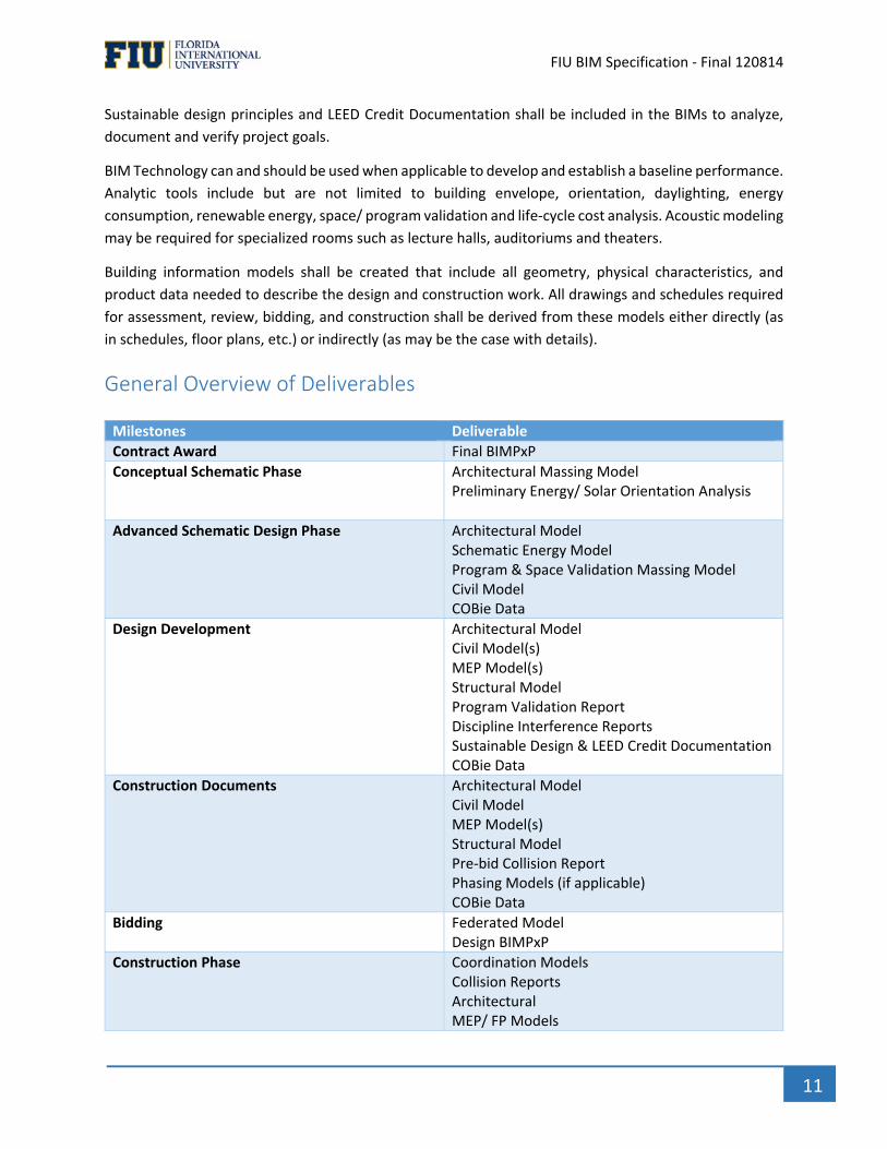
General Overview of Deliverables
Milestones Deliverable
Contract Award Final BIMPxP
Conceptual Schematic Phase Architectural Massing Model Preliminary Energy/ Solar Orientation Analysis
Advanced Schematic Design Phase Architectural Model Schematic Energy Model Program & Space Validation Massing Model Civil Model COBie Data
Design Development Architectural Model Civil Model(s) MEP Model(s) Structural Model Program Validation Report Discipline Interference Reports Sustainable Design & LEED Credit Documentation COBie Data
Construction Documents Architectural Model Civil Model MEP Model(s) Structural Model Pre‐bid Collision Report Phasing Models (if applicable) COBie Data
Bidding Federated Model Design BIMPxP
Construction Phase Coordination Models Collision Reports Architectural MEP/ FP Models

` FIU BIM Specification ‐ Final 120814
12
FIU requires that all design and construction deliverables for BIM projects be created and derived from
Building Information Models (BIMs) and that data associated to be COBie compliant. Both Native File and
IFC File Formats may be required as a final deliverable
All BIMs regardless of software shall be the same scale and in imperial units.
At regular predetermined intervals throughout the design and construction phases FIU will require the
Design & Construction Teams to submit individual BIMs, Federated BIMs, drawings, documents and
COBie files as contract deliverables. These deliverables are complements to the typical 2D deliverable
usually expected from the Design & Construction Teams at each regular project milestone or phase.
Project specific deliverables will be further defined in the BIM Project Execution Plan (BIMPxP).
Two dimensional (2D) documents To promote efficiency and continuity, the 2D construction documents must be extracted directly from
the Design BIMs and both the BIMs and the 2D Deliverables will be integral parts of the contract
documents. Two dimensional details, enlargements, General Notes, externally‐generated Schedules,
and specifications will take precedence over the Design BIMs.
FIU expects 2D Deliverables, namely Site Plans, Plans, Sections, Elevations and the Schedules typically
found in construction documents to be extracted directly from the BIMs. The BIMs shall include all
elements and information needed to produce Permit Documents for Design Intent, Shop Drawings for
Construction installation, Record BIM As‐Built, and COBie data sets.
2D CAD drawing information for the purposes of assembling a printed set of plans shall be derived from
the BIM(s) to the fullest extent possible. All BIM information shall be fully parametric so that all
applicable information regarding fixtures and/or elements can be generated for the schedules.
Ownership & Reuse: The Model Files are considered the intellectual property of the Model authors. Sharing of the Models
does not affect the Model author’s copyright or intellectual property rights in any way.
Upon receipt of any deliverable, Florida International University has and will maintain ownership of all
CAD files, BIM and Facility Data developed for the project.
The Owner will have unlimited use of the Design, Construction and Data Models produced for the
Project. The Owner acknowledges that the Design, Construction and Data Models are an Instrument of
the Designer’s or Contractor’s Service and that the author of the Models does not represent or
Structural Models Fabrication Models (if applicable) Phasing Models COBie Data
Project Close‐out Record Model ‐ Architect As Built Model ‐ Contractor Record Documents Project Drawings O &M Manuals COBie Data

` FIU BIM Specification ‐ Final 120814
13
guarantee that the Models will be useful to the Owner for any purposes beyond those uses that they
were authored for.
BIM Execution Plan The BIM Execution Plan is a living document that will continue to mature over the course of project
deliverable and milestones.
The National Building Information Modeling Standard‐ United States (most current version at contract
award) shall be used as the basis of the BIMPxP. The BIM protocols, roles and responsibilities
customized for the needs of each project requiring BIM will be addressed in the BIMPxP of the Design &
Construction Teams. No more than thirty (30) days after the contract is awarded, a project‐specific
BIMPxP shall be developed. FIU will review the BIMPxP and make comments and suggestions. The
Design & Construction Teams will then have two (2) weeks to incorporate and adopt said changes.
The Architect and Contractor must each submit a BIMPxP that includes roles and responsibilities of the
teams demonstrating a high level of project integration and process workflow. The BIMPxP shall be
developed jointly with both Architect and Contractor when feasible and as early on in the project as
possible.
Upon Contractor or CM selection a Joint BIM Project Execution Plan (JBIMPxP) must be created and will
become the final BIMPxP. All parties including the Architect, Engineers, Contractors, Trades, Owner and
any Consultants affected by its content must agree with signature to the JBIMPxP and will be held
accountable for its content and execution.
At a minimum the BIMPxP and JBIMPxP should address the following:
BIM Project Execution Plan Overview
Project Information
Key Project Contact
Project Goals / BIM Uses
Organizational Roles / Staffing
BIM Process Design
BIM Information Exchanges
BIM and Facility Data Requirements
Collaboration Procedures
Quality Control
Technological Infrastructure Needs
Model Structure
Project Deliverables
Delivery Strategy / Contract
Model Progression Schedule A Model Progression Schedule shall be used as a tool to help Model Contributors throughout the Design,
Construction and Operation phases understand what should be included in the BIMs when at each
project milestone. The MPS shall be based on the CSI’s OmniClass Table 22 Work Results, formerly
known as MasterFormat, the version currently in the NIBMS‐US Standard. It shall be the responsibility of
` FIU BIM Specification ‐ Final 120814
14
the Design & Construction Teams to tailor the MPS to meet the requirements of this standard and their
project‐specific needs. An MPS shall be submitted along with the BIMPxP for review by FIU. You will find
a sample MPS in the Appendix of this document.
LOD vs. Level of Detail When talking about Level of Detail one generally refers to an object, while Level of Development is
generally referred to when evaluating the reliability of the information contained in a building system or
a discipline as relevant to a specific BIM Use Case. For example, a low level of detail object can be part of
an LOD 500 BIM. For the purposes set forth in this standard LOD will always mean Level of
Development. FIU will adopt the definitions established by the BIMForum’s 2013 Draft LOD
Specification.
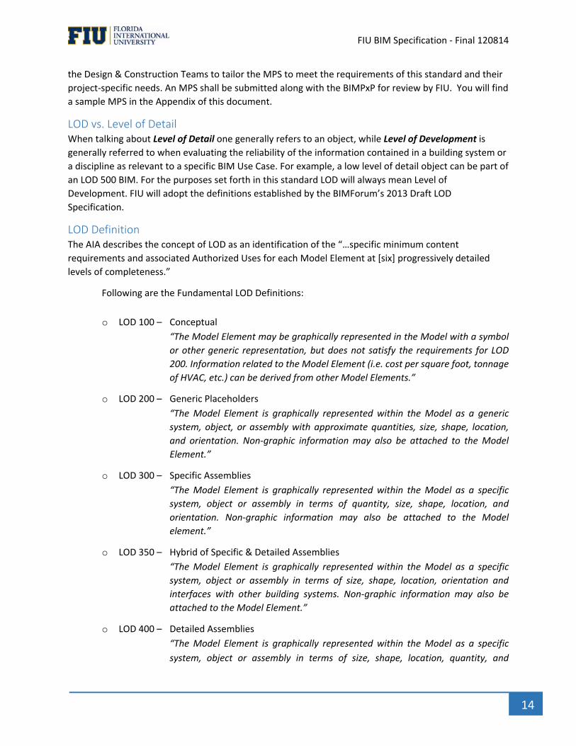
LOD Definition The AIA describes the concept of LOD as an identification of the “…specific minimum content
requirements and associated Authorized Uses for each Model Element at [six] progressively detailed
levels of completeness.”
Following are the Fundamental LOD Definitions:
o LOD 100 – Conceptual
“The Model Element may be graphically represented in the Model with a symbol
or other generic representation, but does not satisfy the requirements for LOD
200. Information related to the Model Element (i.e. cost per square foot, tonnage
of HVAC, etc.) can be derived from other Model Elements.”
o LOD 200 – Generic Placeholders
“The Model Element is graphically represented within the Model as a generic
system, object, or assembly with approximate quantities, size, shape, location,
and orientation. Non‐graphic information may also be attached to the Model
Element.”
o LOD 300 – Specific Assemblies
“The Model Element is graphically represented within the Model as a specific
system, object or assembly in terms of quantity, size, shape, location, and
orientation. Non‐graphic information may also be attached to the Model
element.”
o LOD 350 – Hybrid of Specific & Detailed Assemblies
“The Model Element is graphically represented within the Model as a specific
system, object or assembly in terms of size, shape, location, orientation and
interfaces with other building systems. Non‐graphic information may also be
attached to the Model Element.”
o LOD 400 – Detailed Assemblies
“The Model Element is graphically represented within the Model as a specific
system, object or assembly in terms of size, shape, location, quantity, and
` FIU BIM Specification ‐ Final 120814
15
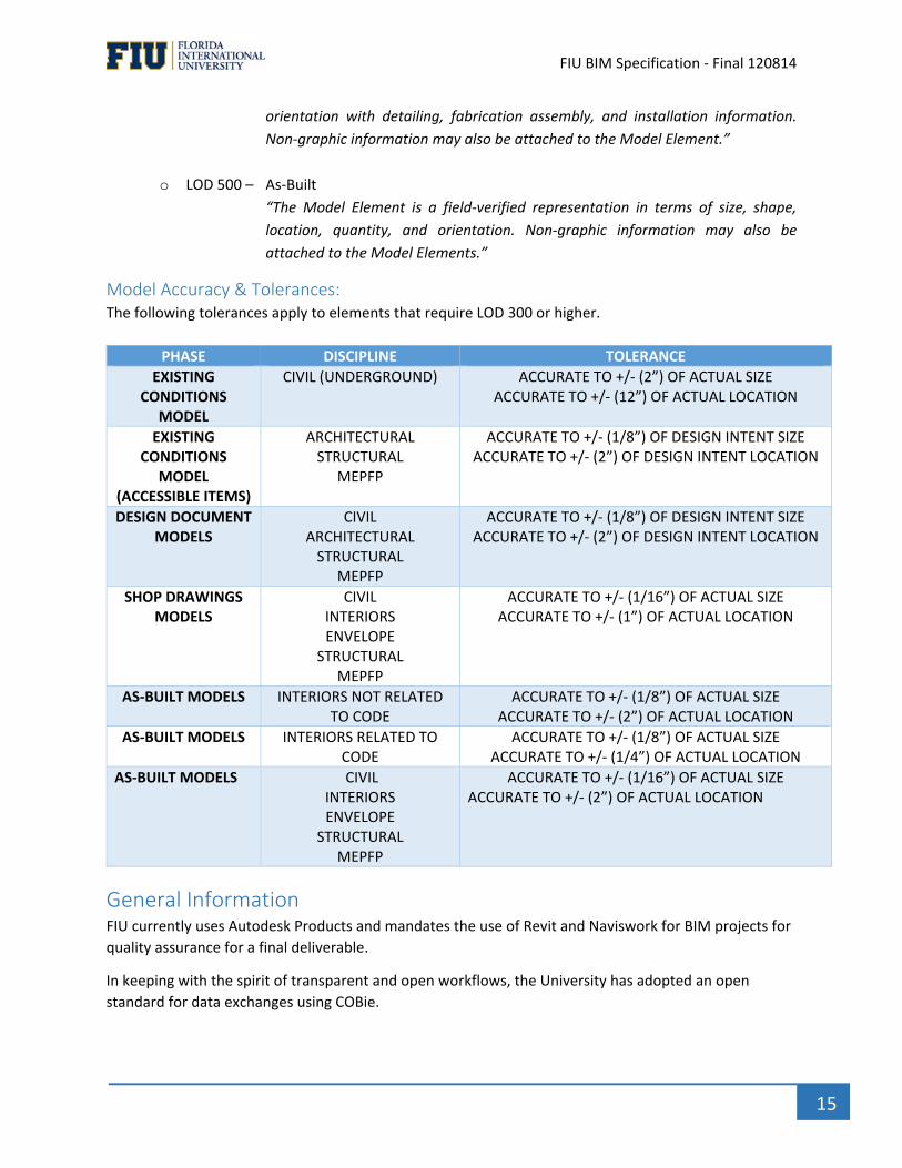
orientation with detailing, fabrication assembly, and installation information.
Non‐graphic information may also be attached to the Model Element.”
o LOD 500 – As‐Built
“The Model Element is a field‐verified representation in terms of size, shape,
location, quantity, and orientation. Non‐graphic information may also be
attached to the Model Elements.”
Model Accuracy & Tolerances: The following tolerances apply to elements that require LOD 300 or higher.
PHASE DISCIPLINE TOLERANCE
EXISTING CONDITIONS
MODEL
CIVIL (UNDERGROUND) ACCURATE TO +/‐ (2”) OF ACTUAL SIZE ACCURATE TO +/‐ (12”) OF ACTUAL LOCATION
EXISTING CONDITIONS
MODEL (ACCESSIBLE ITEMS)
ARCHITECTURAL STRUCTURAL
MEPFP
ACCURATE TO +/‐ (1/8”) OF DESIGN INTENT SIZE ACCURATE TO +/‐ (2”) OF DESIGN INTENT LOCATION
DESIGN DOCUMENT MODELS
CIVIL ARCHITECTURAL STRUCTURAL
MEPFP
ACCURATE TO +/‐ (1/8”) OF DESIGN INTENT SIZE ACCURATE TO +/‐ (2”) OF DESIGN INTENT LOCATION
SHOP DRAWINGS MODELS
CIVIL INTERIORS ENVELOPE
STRUCTURAL MEPFP
ACCURATE TO +/‐ (1/16”) OF ACTUAL SIZE ACCURATE TO +/‐ (1”) OF ACTUAL LOCATION
AS‐BUILT MODELS INTERIORS NOT RELATED TO CODE
ACCURATE TO +/‐ (1/8”) OF ACTUAL SIZE ACCURATE TO +/‐ (2”) OF ACTUAL LOCATION
AS‐BUILT MODELS INTERIORS RELATED TO CODE
ACCURATE TO +/‐ (1/8”) OF ACTUAL SIZE ACCURATE TO +/‐ (1/4”) OF ACTUAL LOCATION
AS‐BUILT MODELS CIVIL INTERIORS ENVELOPE
STRUCTURAL MEPFP
ACCURATE TO +/‐ (1/16”) OF ACTUAL SIZE ACCURATE TO +/‐ (2”) OF ACTUAL LOCATION
General Information FIU currently uses Autodesk Products and mandates the use of Revit and Naviswork for BIM projects for
quality assurance for a final deliverable.
In keeping with the spirit of transparent and open workflows, the University has adopted an open
standard for data exchanges using COBie.
` FIU BIM Specification ‐ Final 120814
16
Design and Construction teams that use software other than Revit and Navisworks must assure data
integration, quality of information, and interoperability with FIU’s databases. The Design and
Construction teams must provide the University with access and visibility to the BIMs during all phases
of the project, while ensuring COBie compliance.
Project Teams must get approval when using products other than the following software: Revit, Civil 3D
and Navisworks. Project teams will be required to show that they have previous experience with the
software and IFC conversions on past projects with references and that they can meet the BIMs and
data exchange requirements that are outlined in this Standard.
Software It is the responsibility of both the Design Team and Prime Contractor to have or obtain, at their cost, the
trained personnel, hardware, and software needed to successfully use BIM for the project. Equipment
used by the subcontractors during the on‐site coordination meetings must meet the requirements of the
software being implemented so as not to cause delays in modeling. All technical disciplines shall be
responsible for their data integration and data reliability of their work and coordinated BIMs.
Compatibility: Software used for Design and Construction team shall be compatible and be Industry
Foundation Class (IFC) certified as needed for IFC deliverables.
Data Exchange Open Standards: To ensure the life‐cycle use of building Information and interoperability between BIMs using competing but approved software, FIU allows that data be exchanged in IFC where applicable. IFC Certification: BIM authoring software shall be certified to the latest release of the Industry
Foundation Class (IFC) performed by the buildingSMART International. A list of IFC certified software
can be found at http://www.buildingsmart.org/compliance/certified‐software/
IFC ‐ The IFC files must come from IFC certified software for export and be the IFC Coordination View (2x3). The coordination view shall contain:
a) Building spatial structure b) Building elements and spaces with their semantic information c) IFC Property sets as well as native properties
Approved vendors: FIU requires parametric, object oriented software applications that are able to be
used in a collaborative environment. All software platforms used for FIU projects shall be compliant
with:
Where required, the most current version of Industry Foundation Class (IFC) certified by building
Smart International
Commercially available collaboration software that provides interoperability between the
different software applications (ex. NavisWorks or equal).
Traditional 2D documentation shall be prepared BIM authoring software and plans, elevations,
sections, schedules, and details shall be derived and fully coordinated with the coordinated
building model.

` FIU BIM Specification ‐ Final 120814
17
Versions Versioning of software shall be managed by the BIM teams throughout the project lifecycle. The version
number of any software to be used including collaboration software (e.g. Revit, Navisworks, etc.) must
be announced at the start of the project and must be maintained throughout the project close‐out
unless the team as a whole agrees to upgrade to a newer version. The versioning of software must be
identified in the BIMPxP.
Geo ‐ Reference The Architects will set the spatial coordinates at the beginning of the project. The coordinates will be
accurately geo‐referenced to a permanent campus monument. This will be coordinated between the
Civil Engineer, the Architects and FIU. It is the Architects responsibility to verify the accuracy of the
coordinates and to provide a grid intersection at 0, 0 for all other team members.
Datum: All objects in models are to be modeled at true scale and at true elevation above sea level in accordance with the datum to be provided by Florida International University.
Project North Definitions: For the purpose of specifying horizontal locations and orientations of objects in models and drawings the following definitions apply: True North: Orientation of objects in a model or a drawing in accordance with the geographical North orientation. Locations have the correct coordinates in accordance with the state plane coordinate system of Florida. Project North: Objects in a model are oriented for convenience of the modeling and drafting process. Project North is one defined orientation and location of the building defined by the Architect‐Engineer and followed by all project participants. Project North must be defined in terms of its rotation angle relative to true North to at least 8 decimal places. Project North: All models and documents shall follow the Project North orientation and location.
File Sharing Platform The Model Files are considered the intellectual property of the Model authors. Sharing of the Models
does not affect the Model author’s copyright or intellectual property rights in any way. FIU requires the
Project Team to establish an accessible file sharing platform, for common access of all BIMs. Project
Teams should update the BIMs on the file sharing platform no less than bi‐monthly during Design and
weekly during Coordination and Construction, or as requested by FIU.
Versioning of files enables an audit trail of the modeling process and enables FIU and the team to
determine which BIM’s constitute the current version. FIU requires that BIMs versions be preserved
through a versioning process and not overwritten. The Version Management Process (VMP) should be
clearly detailed in the BIMPxP so that external reference links can be maintained.
File Structure & Naming All Project central files and model files shall have a consistent naming convention as established by
the principle design firm for discipline specific model coordination. The Design Team BIM Manager
shall coordinate this activity with all sub ‐consultants and design disciplines.

` FIU BIM Specification ‐ Final 120814
18
Model views shall have a consistent naming convention as established by the Design Team BIM
Manager. Consistent view naming allows for the automatic sorting of views for ease of identification.
The protocol facilitates low maintenance of the view name as project conditions change throughout the
Project.
Sheet Sizes and Naming Conventions Preferred format size for Construction Drawings is 24" X 36" (Architectural "D" Size). Other sizes may be
used if required and approved by FIU.
Sheet names should be descriptive of drawing content and the building discipline represented (i.e., A‐1,
P‐1, and M‐1 would be typical designations for Architectural, Plumbing, and Mechanical Drawings,
respectively).
Units and Tolerances For Project Teams using Revit: The Revit Project Units and Tolerances settings affect the way that
information in the model is displayed. It does not limit tolerances of how things are modeled. The
Project will utilize the Revit Project Unit settings as established by the Architect’s model manager.
Modifications to the settings should be made as necessary and agreed to by the Project Team.
Compensation The use of BIM on a project should not result in increased fees, and BIM deliverables at the minimum
levels of development shall be included in the basic fee as negotiated. There are items that should be
reviewed by the owner prior to issuance of the request for qualification and bid document for the
potential cost impact that may be associated with unique modeling and/or data requirements. Requests
for additional embedded data in a model may result in additional service fees to compensate for the
level of effort required. BIM deliverables at a higher LOD required by the owner shall be identified in the
schedule of additional services.
The cost for purchasing BIM authoring software and training will not be compensated by the owner for
the projects requiring BIM implementation. If the owner or contracting authority requires software
license(s) for their use, the costs will be included as a reimbursable expense.
Additional service fees beyond the basic services may be considered for further model development and
enhancement during the construction phase, but not for typical as‐built or post construction
documentation requirements. This remains the CM’s responsibility.
Specific management or coordination requirements of contractor models may be negotiated as
necessary through specific project requirements and additional services if necessary.
Construction manager requirements for BIM management and participation will be described in the
request for qualifications, and will be incorporated into the construction manager’s fee proposal.
Contractor modeling requirements will be described within the bid documents, and will be included in
the contractor’s bid.
BIMS will be used by FIU to verify pay applications and invoicing from the Design and Construction
Teams.
` FIU BIM Specification ‐ Final 120814
19
BIM Roles & Responsibilities The Owner and Project Team roles may vary from project to project depending on the BIM experience and proficiency of that project’s Design and Construction Teams. Following is an overview.
Owners Role & Responsibility The primary role of the Owner is to monitor the BIM processes in all stages of design, construction into Operations and to insure that FIU’s BIM Standard is adhered to throughout design, construction, close‐out and commissioning. Some of the Owners, or Owners representatives’ responsibilities include the following:
a. FIU BIM Standard Oversight: FIU Staff and/or BIM representatives will do regular model and content checks on all Design and Construction BIM projects to ensure that FIU BIM Standards requirements are correctly being delivered and that the BIM data is COBie compliant.
b. Review, evaluate, and comment on the BIM Execution Plans (BIMPxP) provided by both the
Design Team, the General Contractor and the Construction Manager and ensure that it meets with the FIU BIM Standard.
c. Conduct two BIM kickoff meetings: FIU Staff and /or BIM representative will participate in a BIM Project kick‐off meeting at the start of the project with the entire Design Team including major consultants including but not limited to, Mechanical, Electrical, Plumbing, Civil and Structural, which shall be led by the Prime Consultant or its BIM representative. A second meeting will be held upon once a Contractor or Construction Manager has been selected and shall include the Design Team and the major construction trades including, but not limited to, Mechanical, Electrical, Plumbing, Fire Protection, Civil, and Structural, which shall be led by the Prime Contractor or its BIM representative.
d. Conduct BIM review meetings as necessary: FIU Staff and / or BIM Representative will coordinate and participate in BIM review meetings at all phases of design and construction. BIM reviews can include visual examination of the Federated models, model assembly, clash detection for all major trades modeled, and COBie compliance.
e. Model Handover Coordination: FIU Staff and / or BIM Representative will help facilitate the hand‐over of the design BIMs to the general contractor.
f. Date Integration for Facilities Management: FIU Staff and / or BIM Representative will define the FM model / data requirements and review access and clearances to equipment that needs to be serviced and maintained.
Design Team Roles & Responsibility Design Project Manager (PM)
` FIU BIM Specification ‐ Final 120814
20
The Project Manager is the ultimate point of contact for the overall project. The individual can serve as
the BIM Manager if he/she has the relevant BIM experience depending on the size and complexity of the
project.
Design BIM PM (BPM)
The design team shall have a dedicated Project BIM Manager that has sufficient experience for the size
and complexity of the project and shall be proficient in the authoring and coordination of BIMs. This
individual will serve as the main point of contact for project‐related BIM & VDC information.
This Design BIM PM shall be qualified enough to implement the Design BIMPxP and interface with outside
BIM stakeholders. Those stakeholders will include, at a minimum, FIU’s PM and BIM Controller, but may
also include various FIU end user groups, and the Contractor and its subcontractors when they are already
known and are a part of the Design & Construction Teams.
COBie Coordinator
The COBie Coordinator will be responsible for the COBie process including assigning room information in
the Architectural model. All other project models using room information must reference the room
information assigned in the Architectural model. This will ensure the proper location information is
provided in the COBie deliverable. If the case where room‐naming conventions are provided by FIU, the
room names must be strictly enforced in the COBie deliverables. The COBie Coordinator will collect Asset
Data for export to Maximo.
Some of the Design Teams responsibilities include the following:
1. Responsible for the overall development and delivery of the Building Information Model.
2. Monitors compliance with the BIM Execution Plan and related BIM Level of Detail Development
(LOD) Matrix.
3. Responsible for the development, coordination, publication, and verification that all BIM
configurations are in place as required for the integration of the design phase and construction
phase model information, elements, etc.
4. Coordinates the file management procedures and protocols for the BIMs
5. Responsible for the coordination and set‐up of shared file servers to be utilized for the Model,
including related access, permissions, protocols, etc.
6. Prepares, assembles, and facilitates the use of the Model for design meetings, coordination
meetings, and BIM deliverables.
7. Assumes responsibility for the proper classification of all spaces, equipment, and components
within the Model for COBie compliance and Maximo import.
8. Schedules, coordinates, and facilitates BIM technical meetings between all design disciplines
and Owner.
9. Coordinates and facilitates the clash detection and coordination efforts among all design
disciplines.
10. Determines the project BIM geo‐reference point(s), and ensures that the models from all design
disciplines are properly referenced and coordinated with the geo‐reference point(s).
` FIU BIM Specification ‐ Final 120814
21
11. Primary interface with FIU Facilities Group and IT Managers for BIM data and file transfers as
required at each design phase or otherwise necessary.
12. Ensures that the BIM design deliverables specified and/or required by contract are provided in
accordance with the Contract Documents.
13. Ensures that the 2D project drawings and project specifications produced for bidding and construction purposes are properly derived from and adequately represent the information
contained within the Model.
14. Coordinates with the Construction BIM Manager to ensure that all requirements for the final
BIMs deliverables are achieved.
15. Coordinates with the Construction BIM Manager on the JBIMPxP.
Construction Team Roles & Responsibility
Construction PM (PM)
The Project Manager is the ultimate point of contact for the overall project. This individual can also serve
as the BIM Manager for the project if he/she has the relevant BIM experience with the size and complexity
of the project.
Construction BIM PM (BPM)
The Construction team shall have a dedicated BIM PM to the project that has sufficient experience for the
size and complexity of the project and shall be proficient in the management of project BIMs. This
individual will serve as the main point of contact for BIM. The Construction BIM PM shall be qualified to
implement the Construction BIMPxP and interface with outside BIM stakeholders.
COBie/ Information Coordinator
The Construction COBie Coordinator will be responsible for coordinating the COBie process with the
design team’s COBie Coordinator and for completing his/her assigned portion of the COBie deliverable
including make, model, description, serial number and installation date.
Some of the Construction Teams responsibilities include the following:
1. Coordinates with Design Team BIMPM on the creation of the JBIMPxP.
2. Responsible for the overall development of BIMs content and information that is developed
from construction operations.
3. Serves as the main point of contact for BIM related issues between the Construction Team,
Subcontractors, Suppliers, and the Design Team, FIU, and others as required.
4. Ensures that the Construction Team has the necessary hardware, BIM authoring and analysis
software, and adequate training to facilitate the use of the BIMs as a tool during construction.
5. Responsible for the integration and/or coordination of the construction schedule with the
Construction BIMs.
6. Facilitates the use of trade models for the purpose of trade coordination and clash detection
(when available or provided by trade contractors).
7. Communicates requests by trade contractors for data extraction sets to the Design Team and
ensures that these requests are fulfilled.
8. Coordinates with the Design Team to facilitate timely updates to the Construction BIMs for
design changes that may occur after construction has commenced
` FIU BIM Specification ‐ Final 120814
22
9. Works with Lead Trade Fabrication Modelers as may be required for procurement and
construction activities.
10. Coordinates updates to the BIMs as necessary to reflect the “as‐built” or “as‐constructed”
conditions in the final As‐Built BIMs.
Process and BIM Workflows BIM is a process for creating and managing all of the information on a project – before, during and after
construction. The true value of BIM can only be realized when it is taken beyond the design team – to
subcontractors, the owner and facility managers. Designing and building is a complex process that
requires a tremendous amount of collaboration, dedication and hard work. Using the BIM Process
defined below, Project teams can benefit from BIM by utilizing models created by all members of the
design and construction team to improve project coordination and scheduling while also improving
overall quality while minimizing project risk. This FIU BIM Standard is intended to incorporate BIM as an
integral part of FIU’s Planning, Design, Construction and Facilities Management processes. Any deviation
of this guide must be documented in advance by the Project Team and then reviewed and approved by
FIU prior to commencement.
General Requirement The 3D models shall consist of 3D‐Solids (not lines or wire frames) that represent the actual dimensions
of the building elements and the equipment that will be installed on the project.
Existing Conditions The Design Team shall model all existing conditions needed to explain the extent of the construction work for alterations and additions projects. The extent of modeling beyond the affected areas and the level information to be included will be determined based on project needs. These requirements may be stated in the project program or discussed during the project kickoff meeting. The BIMPxP should define the agreed upon scope of the modeling effort.
Topographic and Property Line Surveying Detailed requirements of what is to be included in surveying deliverables is managed by FIU staff in consultation with the Design Team on a project‐by‐project basis. Surveys shall be provided in electronic format and should include at minimum: 3D topographic information, paving and retaining walls. The file(s) shall be in a format that allows for importing into the Design Team’s BIM authoring software.
Model Information Requests (MIR) / Request for Information (RFI) Establishing a collaborative use of the BIMs during the design and construction process, the Designers, Contractors, and FIU can work proactively to resolve issues together and reduce the number of RFI’s / MIR’s generated. Project BIMs shall be used for model geometry and extract graphical information for generating Model Information Requests. Clash reports may also be issued by the General Contractor as background information for MIRs The design and construction teams will be responsible for timely updates to their models based on MIR and RFI responses. The architect’s BIM manager will work with their consulting engineers to incorporate changes or updates to their models and the General Contractors / Construction Managers BIM manager will update the Construction model(s).
` FIU BIM Specification ‐ Final 120814
23
Contractor’s fabrication models shall be coordinated with the design model. Any conflicts to the design model that need to be made prior to fabrication and construction shall be reported to the Design Team in the form of MIR. If required by contract, the Design Team will manage and update the Design BIM(s) through the end of the construction phase, incorporating all updates and/or revisions to the model(s) as necessary to reflect design changes initiated by MIR, RFI, Owner Changes, or coordination with existing conditions.
Change Orders It is the Construction Team’s responsibility to ensure that Clash Detection and Coordination is used to the fullest extent in order to avoid any problems during installation. FIU will not accept change orders due to failed construction BIM coordination. Coordination shall be complete and the Construction Federated BIM shall show zero non‐justified clashes between the Building components prior to construction and installation.
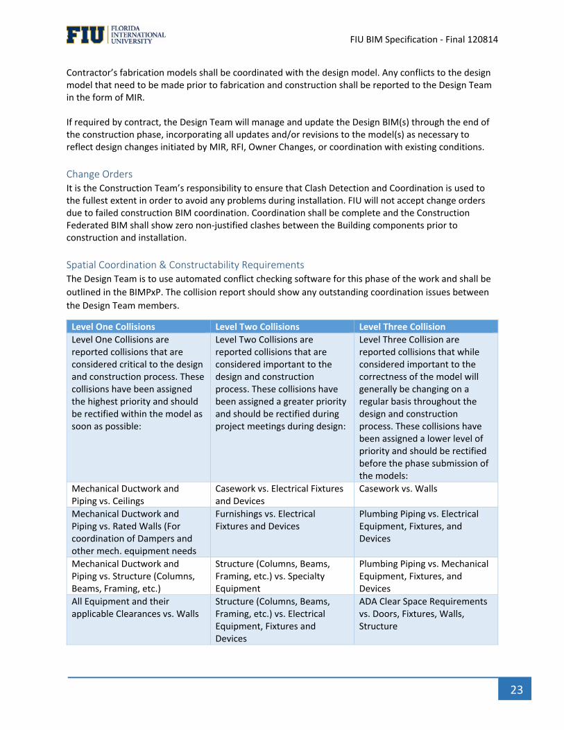
Spatial Coordination & Constructability Requirements The Design Team is to use automated conflict checking software for this phase of the work and shall be
outlined in the BIMPxP. The collision report should show any outstanding coordination issues between
the Design Team members.
Level One Collisions Level Two Collisions Level Three Collision
Level One Collisions are reported collisions that are considered critical to the design and construction process. These collisions have been assigned the highest priority and should be rectified within the model as soon as possible:
Level Two Collisions are reported collisions that are considered important to the design and construction process. These collisions have been assigned a greater priority and should be rectified during project meetings during design:
Level Three Collision are reported collisions that while considered important to the correctness of the model will generally be changing on a regular basis throughout the design and construction process. These collisions have been assigned a lower level of priority and should be rectified before the phase submission of the models:
Mechanical Ductwork and Piping vs. Ceilings
Casework vs. Electrical Fixtures and Devices
Casework vs. Walls
Mechanical Ductwork and Piping vs. Rated Walls (For coordination of Dampers and other mech. equipment needs
Furnishings vs. Electrical Fixtures and Devices
Plumbing Piping vs. Electrical Equipment, Fixtures, and Devices
Mechanical Ductwork and Piping vs. Structure (Columns, Beams, Framing, etc.)
Structure (Columns, Beams, Framing, etc.) vs. Specialty Equipment
Plumbing Piping vs. Mechanical Equipment, Fixtures, and Devices
All Equipment and their applicable Clearances vs. Walls
Structure (Columns, Beams, Framing, etc.) vs. Electrical Equipment, Fixtures and Devices
ADA Clear Space Requirements vs. Doors, Fixtures, Walls, Structure
` FIU BIM Specification ‐ Final 120814
24
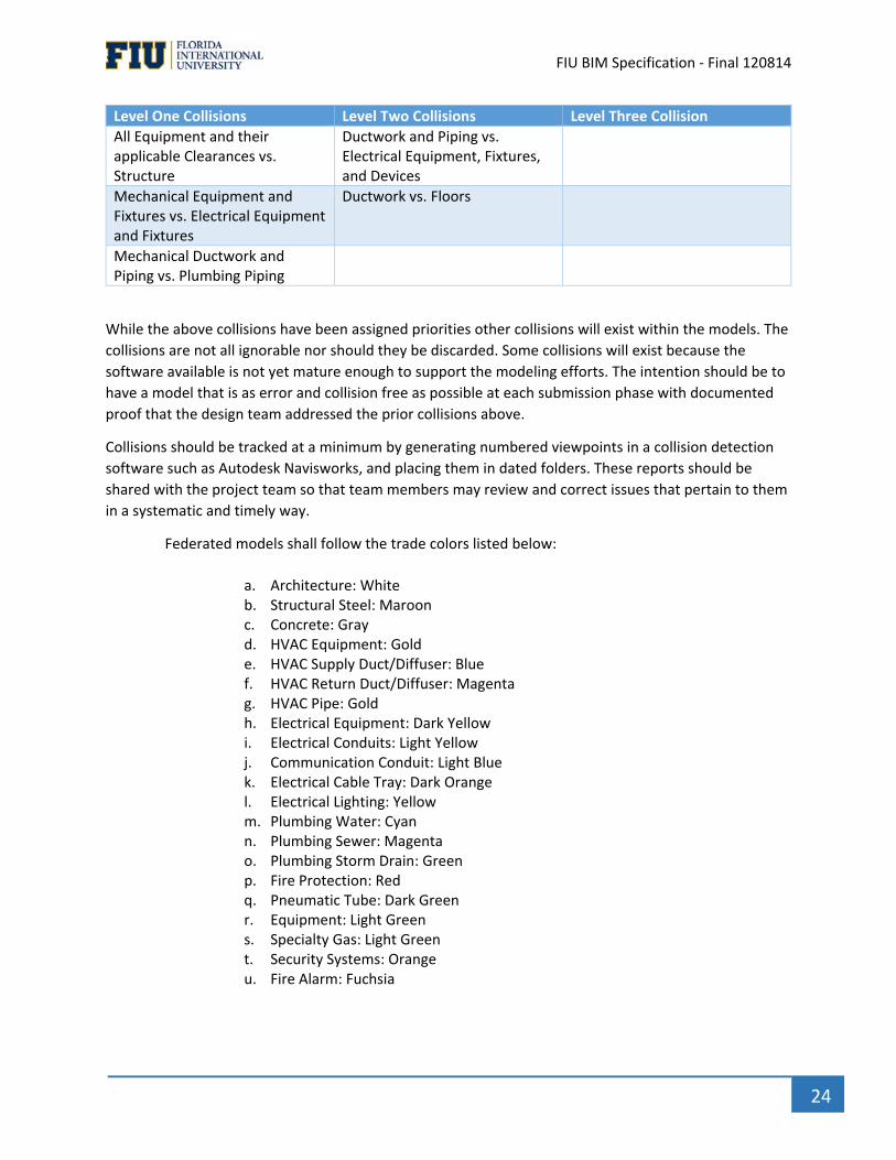
Level One Collisions Level Two Collisions Level Three Collision
All Equipment and their applicable Clearances vs. Structure
Ductwork and Piping vs. Electrical Equipment, Fixtures, and Devices
Mechanical Equipment and Fixtures vs. Electrical Equipment and Fixtures
Ductwork vs. Floors
Mechanical Ductwork and Piping vs. Plumbing Piping
While the above collisions have been assigned priorities other collisions will exist within the models. The
collisions are not all ignorable nor should they be discarded. Some collisions will exist because the
software available is not yet mature enough to support the modeling efforts. The intention should be to
have a model that is as error and collision free as possible at each submission phase with documented
proof that the design team addressed the prior collisions above.
Collisions should be tracked at a minimum by generating numbered viewpoints in a collision detection
software such as Autodesk Navisworks, and placing them in dated folders. These reports should be
shared with the project team so that team members may review and correct issues that pertain to them
in a systematic and timely way.
Federated models shall follow the trade colors listed below:
a. Architecture: White b. Structural Steel: Maroon c. Concrete: Gray d. HVAC Equipment: Gold e. HVAC Supply Duct/Diffuser: Blue f. HVAC Return Duct/Diffuser: Magenta g. HVAC Pipe: Gold h. Electrical Equipment: Dark Yellow i. Electrical Conduits: Light Yellow j. Communication Conduit: Light Blue k. Electrical Cable Tray: Dark Orange l. Electrical Lighting: Yellow m. Plumbing Water: Cyan n. Plumbing Sewer: Magenta o. Plumbing Storm Drain: Green p. Fire Protection: Red q. Pneumatic Tube: Dark Green r. Equipment: Light Green s. Specialty Gas: Light Green t. Security Systems: Orange u. Fire Alarm: Fuchsia

` FIU BIM Specification ‐ Final 120814
25
BIM Use Matrix Minimum Requirements The BIM Uses currently highlighted in green and checked with an (Y) are required by FIU at a minimum.
Additional BIM uses may be selective and on a per project basis and will be detailed either in the Project
initial request for information or contract. This BIM Use Matrix must be competed and incorporated into
the BIMPxP and agreed upon by all project participants
Y Plan Y Design Y Construct Y Operate PROGRAMMING Y DESIGN AUTHORING SITE UTILIZATION
PLANNING BUILDING SYSTEM ANALYSIS
SITE ANALYSIS Y PROGRESS REVIEWS Y CONSTRUCTION SYSTEM DESIGN
ASSET MANAGEMENT
CAMPUS MASTER MODEL INTEGRATION
Y 3D COORDINATION AND CLASH DETECTION
Y 3D COORDINATION AND CLASH DETECTION
SPACE MANAGEMENT AND TRACKING
NAMING CONVENTIONS STRUCTURAL ANALYSIS
DIGITAL FABRICATION DIASTER PLANNING
ENERGY ANALYSIS
Y RECORD MODEL Y BIM2MAXIMO
LIGHTING ANALYSIS FIELD AND MATERIAL TRACKING
Y PROGRAM VALIDATION
DIGITAL LAYOUT –BIM2FIELD
MECHANICAL ANALYSIS
OTHER ENG. ANALYSISSUSTAINABILITY (LEED) EVALUATION
LASER SCANNING AND POINT CLOUD INTEGRATION
PROGRAM / CODE VALIDATION
PRELIMINARY CONSTRUCTION SCHEDULING (4D)
CONSTRUCTION SCHEDULING (4D)
COST ESTIMATION (5D)
COST ESTIMATION (5D)
AS BUILT MODEL Y AS BUILT MODEL
EXISTING CONDITION MODELING
Y EXISTING CONDITIONS MODELING
EXISTING CONDITION MODELING
EXISTING CONDITION MODELING
CONSTRUCTION OPERATIONS BUILDING INFORMATION EXCHANGE (COBie)
CONSTRUCTION OPERATIONS BUILDING INFORMATION EXCHANGE (COBie)
CONSTRUCTION OPERATIONSBUILDING INFORMATION EXCHANGE (COBie)
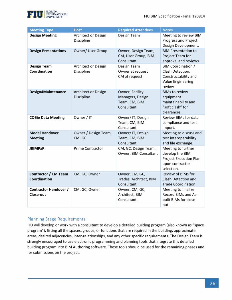
Progress of Models & Review There will be different types of Collaboration and model review meetings needed for the project,
including general progress meetings, design coordination meetings, etc. The following table includes,
but is not limited to, some of the types of potential meetings necessary for the project, meeting host(s),
required attendees, and required technology. FIU understands that these meeting may be actual, virtual
and/ or a combination of both.
Meeting Type Host Required Attendees Notes
BIMPxP Meeting Prime Consultant Design Team, Owner, BIM Consultant
Meeting to develop BIM Execution Plan.
` FIU BIM Specification ‐ Final 120814
26
Meeting Type Host Required Attendees Notes
Design Meeting Architect or Design Discipline
Design Team Meeting to review BIM Progress and Project Design Development.
Design Presentations Owner/ User Group Owner, Design Team, CM, User Group, BIM Consultant
BIM Presentation to Project Team for approval and reviews.
Design Team Coordination
Architect or Design Discipline
Design Team Owner at request CM at request
BIM Coordination / Clash Detection. Constructability and Value Engineering review
Design4Maintenance Architect or Design Discipline
Owner, Facility Managers, Design Team, CM, BIM Consultant
BIMs to review equipment maintainability and “soft clash” for clearances.
COBie Data Meeting Owner / IT Owner/ IT, Design Team, CM, BIM Consultant
Review BIMs for data compliance and test import.
Model Handover Meeting
Owner / Design Team, CM, GC
Owner/ IT, Design Team, CM, BIM Consultant
Meeting to discuss and test interoperability and file exchange.
JBIMPxP Prime Contractor CM, GC, Design Team, Owner, BIM Consultant
Meeting to further develop the BIM Project Execution Plan upon contractor selection.
Contractor / CM Team Coordination
CM, GC, Owner Owner, CM, GC, Trades, Architect, BIM Consultant
Review of BIMs for Clash Detection and Trade Coordination.
Contractor Handover / Close‐out
CM, GC, Owner Owner, CM, GC, Architect, BIM Consultant.
Meeting to finalize Record BIMs and As‐built BIMs for close‐out.
Planning Stage Requirements FIU will develop or work with a consultant to develop a detailed building program (also known as “space
program”), listing all the spaces, groups, or functions that are required in the building, approximate
areas, desired adjacencies, inter‐relationships, and any other specific requirements. The Design Team is
strongly encouraged to use electronic programming and planning tools that integrate this detailed
building program into BIM Authoring software. These tools should be used for the remaining phases and
for submissions on the project.
` FIU BIM Specification ‐ Final 120814
27
Area Calculations The Design Professional shall calculate the area of the project using the following method and compare
this information to the owner’s requirements as outlined in the detailed building program.
Area calculations shall be determined as follows:
1. Building Gross Square Feet: Determine the total building gross square feet by adding the sum of the
floor areas of the building included within the outside faces of exterior walls for all stories, or areas that
have floor surfaces. Gross area should be computed by measuring from the outside face of exterior
walls, disregarding cornices, pilasters, buttresses, etc., which extend beyond the wall face. Gross area
should include basements (except unexcavated portions), attics, garages, enclosed porches, penthouses,
mechanical equipment floors, lobbies, mezzanines, all balconies (inside and outside) utilized for
operational functions, and corridors, provided they are within the outside face lines of the building.
Stairways, elevator shafts, mechanical service shafts, and ducts are to be counted as gross area on each
floor through which the shaft passes. Exclude open courts and light wells, portions of upper floors
eliminated by rooms or lobbies that rise above single floor height, and non‐enclosed covered walkways.
2. Net Assignable Square Feet: Determine the sum of room areas excluding non‐assignable areas. Room
area is defined as the net area of the room in square feet, measured between the inside surfaces of
walls and partitions. Non‐assignable areas include interior circulation space (including stairs), custodial
areas, mechanical areas, structural areas, public rest rooms, exterior circulation space (including stairs),
elevators, and telephone/data communication equipment areas.
3. Non‐Assignable Square Feet: Determine the net room area of all non‐assignable spaces as defined in
Item 2 above.
4. Covered Walkway Gross Square Feet: Measure floor area, excluding any areas which were included in
Building Gross Square Feet calculations.
5. Impervious Surface Gross Square Feet: Measure impervious surfaces created as part of the project
site plan including sidewalks, service drives, parking, plazas, etc. that are not covered in Paragraph 3
above.
Program Deliverables At a minimum a CSV Format spreadsheet will be required to track and compare requirements to actual
as it relates to the detailed building program. Variances must be notes and explained.
Design Stage Requirements All information needed to describe the “detailed design” shall be graphically or alphanumerically included in and derived from these models only, except for the Specifications. Documentation of the models shall not happen outside of the BIM Authoring software.
Model Content Requirements A Model Progression Schedule shall be used as a tool to help Model Contributors throughout the Design,
Construction and Operation phases understand what should be included in the BIMs when at each
project milestone. It is the responsibility of the Design and Construction Team to use the MPS as part of
the BIMPxP to establish how they progressively reach FIU’s expectations. FIU defines a minimum BIM
content expectation for CD’s at an LOD 300.

` FIU BIM Specification ‐ Final 120814
28
Architecture:
Model the architectural elements to a level that defines the design intent and accurately represents the design solution. The detail and responsibility to fulfill these modeling requirements should be addressed fully within the BIM Execution Plan. The model shall include the following architectural elements:
Architectural Site plan • Paving, grades, sidewalks, curbs, gutters, site amenities and other elements typically
included on enlarged scale site drawings in building vicinity.
Existing conditions to the extent required
Demolished items to the extent required
New interior and exterior walls including but not limited to: • Doors, windows, openings, louvers and vents. • Interior and exterior soffits, overhangs, sun control elements • Parapets, screening elements • Architectural precast
Floor, ceiling and roof systems including but not limited to: • Appropriate structural items listed below if not provided by the structural engineer and • Integrated into the architectural model for coordination and document generation. • Insulation, ceiling systems, and floor are to be included. • Roof, floor and ceiling slopes, if needed, shall be modeled. • Soffits, openings, scuppers, conductor heads, downspouts, gutters and accessories will
also be modeled.
Elevators, stairs, ramps, guardrails for balconies and level changes, and railings for stairs and ramps should be included.
Casework, shelving, and other interior architectural elements
Furnishings, fixtures, and equipment (if not provided by others and integrated into the architectural model for coordination and document generation.)
Furniture (Fixed and Loose)
Furniture Systems
Specialty equipment (food service, medical, etc.)
Model mechanical, electrical and plumbing items that require architectural space (toilets/sinks/etc.), require color/finish selection (louvers, diffusers, etc.) or affect 3D visualization (lighting fixtures) unless provided by engineers.
Clearance zones for access, door swings, service space requirements, gauge reading, and other operational clearance must be modeled as part of all equipment and checked for conflicts with other elements. These clearance zones should be modeled as invisible solids within the object.
Structural
Model the following structural elements. The detail and responsibility to fulfill these modeling requirements should be addressed fully within the BIM Execution Plan. The model shall include the following structural elements: Foundations such as:
Spread Foundations
Caisson Foundations
` FIU BIM Specification ‐ Final 120814
29
Pile Foundations
Mat Foundations
Load‐bearing Wall Foundations Framing such as:
Steel Columns (with correct shape and size)
Steel Floor C‐Joists
Open Web Joists
Joist Girders
Steel Beams (with correct shape and size)
Precast Concrete Elements (Hollow Core Plank may be modeled as a slab unless the hollow core is being used for mechanical systems and coordination with those systems needs to occur)
Cast‐In‐Place Concrete Elements
Floors including overall extents and openings
Model overall thickness of wood floor systems
Wood Posts/Column
All other Joists
Wood Trusses
Solid Wood or Laminated Beams Wall Types including openings
Load Bearing Walls – for calculations only (Masonry, Concrete, Cold‐Formed Steel, and Wood)
Model overall thickness of Cold‐Formed Steel and Wood Stud walls (individual members may be modeled at the Design Team’s option)
Structural Foundation Walls including brick ledges These items may be modeled at the Design Team’s option:
Steel reinforcing in concrete
Embeds in concrete Miscellaneous Steel
Angles for openings, deck bearing, etc.
Channels for mechanical units needed for coordination reviews between structural and mechanical
Lintels (unless considered a major member)
HVAC
Model the following HVAC elements at a minimum. The detail and responsibility to fulfill these modeling requirements should be addressed fully within the BIMPxP. The model shall include the following HVAC elements:
Equipment • Fans, VAV’s, compressors, chillers, cooling towers, air handlers etc.
Distribution • Supply, return, exhaust, relief and outside air ductwork modeled to outside face
dimension or duct insulation (whichever is greater) • Duct Joints • Diffusers, grilles, louvers, hoods, radiant panels, perimeter units, wall units
Pipes larger than 3/4” diameter, include any insulation in model.
` FIU BIM Specification ‐ Final 120814
30
Clearance zones for access, door swings, service space requirements, gauge reading, and other operational clearance must be modeled as part of the HVAC equipment and checked for conflicts with other elements. These clearance zones should be modeled as invisible solids within the object.
Electrical System
Model the following Electrical elements at a minimum. The detail and responsibility to fulfill these modeling requirements should be addressed fully within the BIMPxP. The model shall include the following Electrical elements:
Power and Telecommunications • Interior and exterior transformers, emergency generators, and other equipment • Main and distribution panels and switchgear including access clearances • Main IDF’s • Feeders and conduit larger than 3/4”diameter • Outlets, switches, junction boxes and pull boxes
Lighting • Permanently mounted lighting fixtures (moveable, plug‐in fixtures need not be modeled
as part of the electrical package unless needed for plug load calculations or for estimating purposes within a loose furnishings package. Should be discussed and agreed upon within the BIM Execution Plan)
• Lighting Controls and sensors • Switches • Junction Boxes
Fire Alarm and Security Systems • Input devices • Notification devices • Associated equipment and access clearances • Permanently mounted fixtures
Building Controls
Clearance zones for access, door swings, service space requirements, gauge reading, valve clearances and other operational clearance must be modeled as part of the electrical equipment for collision checking. These clearance zones should be modeled as invisible solids within the object.
Plumbing & Fire Protection
Model the following Plumbing & Fire Protection elements at a minimum. The detail and responsibility to fulfill these modeling requirements should be addressed fully within the BIMPxP. The model shall include the following Plumbing & Fire Protection elements:
• Waste and Vent Piping sized at and over 3/4” diameter, includes any insulation in model. • Roof and floor drains, leaders, sumps, grease interceptors, tanks, water treatments and
other major items. • Supply Piping larger than 3/4” diameter, includes any insulation in model.
• Domestic Booster Pumps • Fixtures: sinks, toilet fixtures, water tanks, floor sinks
` FIU BIM Specification ‐ Final 120814
31
• Fire protection • Sprinkler lines larger than 3/4”diameter • Sprinkler heads, Fire Protection Pumps • Stand pipes, wall hydrants, fire department connections, risers, including valve
clearances • Clearance zones for access, service space requirements, gauge reading, valve clearances and
other operational clearance must be modeled as part of the plumbing and fire protections system and checked for conflicts with other elements. These clearance zones should be modeled as invisible solids within the object.
Civil Engineering
Model the following Civil elements at a minimum. The detail and responsibility to fulfill these modeling requirements should be addressed fully within the BIMPxP. The model shall include the following Civil elements:
• Topography – 3D terrain of all site work as designed, including retaining walls. This model should include the site and surrounding areas that contribute to the site’s drainage system or otherwise impact on the site. In most cases this will require that adjacent roadways be modeled.
• Landscaping elements: planting areas, such as raised planting beds and berms, parking islands, pools/ponds/other water features, terraces and other items not included elsewhere in the model.
• Storm water management structures, pump stations, fueling systems, manholes and other major items that impact on the overall project understanding or which may become project design constraints. All items must be geo‐referenced such that all elements can be viewed as an overlay in the building information model.
Specialty Consultants
Model the following Specialty elements at a minimum. The detail and responsibility to fulfill these modeling requirements should be addressed fully within the BIMPxP. The model shall include the following Specialty elements:
Equipment provided or specified by said consultant • Rough‐in connection points for power, data, communications, water service and waste, gas,
steam, or other needed utilities. • Extent of specialty consultant modeling shall be coordinated with the Design Team and
described in the BIM Execution Plan. • Clearance zones for access, doors swings, service space requirements, controls, gauge reading,
and other operational clearance must be modeled as part of the equipment and checked for conflicts with other elements.
Design Deliverables The Design Team shall be responsible for providing a coordinated and assembled BIM in a collaboration
software format (Navisworks or equal) and separate copies of each technical discipline model in the
original software authoring tool, as well as a 2D plan set including Specification Manual, derived from
the assembled BIM, for contract bidding. (See table above)
` FIU BIM Specification ‐ Final 120814
32
Design Team ‐ Native file format(s) of Design Models (version as agreed in BIMPxP)
Design Team – Native file of federated Design Coordination model
Design Team ‐ IFC (Coordination View) files at 100% CDs or final design stage deliverable
Design Team— Provide COBIE compliant file containing room and product data information (see COBie
Section of the Standard)
Bidding Phase During bidding, the use of BIM Standards will be announced and reviewed with potential bidders, and
then reviewed with the selected General Contractor and major sub‐contractors prior to the start of
construction. The solicitation for bids shall define the legal status of the model to the bidders (binding,
informational, reference, etc.) by determining the Contract Record Document (the Model(s) or the
extracted 2D plan set).
Contractor Bidding Contractors who are bidding on this project are to review the BIM Execution Plan, this FIU’s BUILDING INFORMATION MODELING (BIM) Standard for bidding. Contractor will follow the guidelines and requirements as set forth by the BIM Execution Plan and this Standard.
Construction Phase Requirements It is the Contractor's responsibility to assure that all major trades are modeled and used for clash
detection, construction phasing, and installation coordination.
General During construction the Design Team shall update the models with all addendum, accepted alternates and/or value enhancement proposals and share those updated models with the Construction team in a timely manner.
Model Sharing The Contractor shall have access to the Design BIMs during construction. Regardless of whether or not
the Design Models(s) is the Contract Record Document, after a contract is awarded for construction the
coordinated design BIM and all native BIM files shall be provided to the appropriate contractor entities
as needed.
The Contractor shall review the BIM Execution Plan with the Design Team and FIU and submit any Addendums within thirty (30) days of contract award. The Design Team and FIU will review and approve of any Addendum within fourteen (14) days of submittal.
Model Content Requirements A Model Progression Schedule shall be used as a tool to help Model Contributors throughout the Design, Construction and Operation phases understand what should be included in the BIMs when at each project milestone. The Construction Models should reflect the exact geometric properties of the materials and/or systems being submitted. These models should reflect the exact material properties and performance data. It is the responsibility of the Design and Construction Team to use the MPS as part of the BIMPxP or JBIMPxP to establish how they progressively reach FIU’s expectations. FIU defines a minimum BIM content expectation for Construction Coordination at an LOD 350.
` FIU BIM Specification ‐ Final 120814
33
The models shall include, but are not limited to:
1. Architectural Model
Wall thickness and height – Required for routing main utilities, locating VAV boxes, identifying
priority wall framing, wall penetrations, fire stopping.
Hard ceilings and soffits – Required for identifying HVAC diffuser locations, electrical fixture
locations, and routing of utilities with openings for diffusers and lights.
Exteriors walls / storefront – Required for identifying the location of rain water leaders.
Shafts, wall chases – Required for identifying the correct locations of plumbing vents, and HVAC
shafts.
Architectural features requiring utilities – Required for utility routing.
Architectural features in mechanical spaces – Required for utility routing.
2. Structural Model
• Beams and columns
• Braces and gusset plates
• Supplemental steel
• Miscellaneous supports for equipment, toilet partitions, etc.
• External wall framing connections
3. Drywall/Framing Model
• Studs, bottom and top track
• Kickers or other drywall supports
• Roof framing
4. Concrete
• Footings and foundations
• Area of influence zones under foundations
• Slabs and slab depressions
5. Mechanical Model
• Medium pressure duct – Required for coordination and routing of other trades as well as pre‐
fabrication.
• Low pressure duct – Required for coordination and routing of other trades as well as pre‐
fabrication.
• Shaft locations – Required for coordination and routing of other trades and for locating smoke
dampers, etc.
• Flanges
• VAV boxes – Required for pre‐fabrication purposes, coordination with HVAC heating hot water
piping, tagged with correct Equipment ID.
• Fire smoke dampers – Required in coordination, tagged with correct Equipment ID.
• Flex ducts – Required for showing how low pressure ducts connect to the diffusers.
` FIU BIM Specification ‐ Final 120814
34
• Diffuser locations and sizes – Required for coordination of finish utilities with the other fixtures
in a room (like electrical fixtures, etc.).
• All duct and pipe insulation – Should be included where required so that the maximum sizes are
represented in the model. – Required for coordination.
• Hangers and seismic bracing – Required for coordination and routing of other trades and for
inserting the deck correctly before installation begins.
• HVAC piping to VAV boxes – Main lines are required for coordinating with other trades; also
required if they will be pre‐fabricated; connections to VAV boxes can be left for field routing.
• HVAC piping to Equipment – Main lines are required for coordinating with other trades; also
required if they will be pre‐fabricated; final connections to equipment need to be coordinated
on model as well.
• Underground utilities ‐ required for underground MEP / FP coordination.
• Mechanical room
• All equipment – Required for coordinating with other trades, tagged with correct Equipment ID.
6. Electrical Model
• Branch and feeder conduits – Required for coordination with other trades and for pre‐
fabrication. Conduits 3/4” and greater need to be modeled. Flex and MC not required.
• All underground conduits – Required for underground MEP / FP coordination.
• Junction boxes and Pull Boxes – Required for coordination with other trades.
• Lighting fixtures – Required for coordination with other trades and finish utilities like ceiling grid,
sprinkler heads, HVAC diffusers and specialty lighting. Tag with Circuit number.
• All lighting supports for special lighting – Required for routing and coordination of other trades.
• Cable trays and other supports – Required for coordination with other trades.
• Hangers and seismic bracing – Required for coordination with other trades and for inserting the
deck.
• Equipment Panels – Required for coordinating with wall framing to determine backing, etc. Tag
with Panel number.
• Electrical rooms – Required for coordination with wall framing and other trades.
• Bundles of cable or wiring – Useful for coordination and pre‐fabrication.
• Outlets and switch locations in rooms – Useful for pre‐fabrication and coordination. Tag with
Circuit number.
• Electrical power off buttons
• All equipment including transformers, TVSS devices, etc. – Required for coordinating with other
trades.
7. Plumbing Model
• Plumbing fixtures – Required for coordination with other MEP trades.
• Graded cast iron pipe lines – Required for coordination with other trades and pre‐ fabrication.
• Underground storm and sewer pipes – Required for underground utilities coordination and for
prefabrication.
• Waste and vent lines – Required for coordination with other trades and with architectural walls,
shafts and for pre‐fabrication.
` FIU BIM Specification ‐ Final 120814
35
• Cold and hot water piping – Required for coordination with other trades and for pre‐fabrication.
Identify valves and tag with appropriate valve number.
• Hangers and seismic bracing details – Required for coordination with other trades and for
inserting before installation.
• Specialty piping – Required for coordination with other trades and for pre‐ fabrication.
• All equipment – Required for coordination.
8. Sprinkler Model
• Sprinkler mains and branches – Required for coordination with other trades and for pre‐
fabrication.
• Sprinkler head drops – Required for coordination with finish utilities like electrical lighting,
diffusers, etc.
• Sprinkler pipes – Required if hard pipe is used, useful if the newer type of flex pipe is used.
• Hangers and seismic bracing – Required for coordination with other trades and for inserting the
deck
• Correctly before installation begins.
• Underground utilities ‐ required for underground MEP / FP coordination.
• All equipment – Required for coordination.
9. Process Piping Model
• Process piping – All piping, valves, actuators, and fittings required for coordination with other
trades.
• Hangers and seismic bracing – Required for coordination and routing of other trades and for
inserting the deck correctly before installation begins.
• Process equipment – A model of each piece of equipment must be provided by the equipment
manufacturer for coordination with other trades.
10. Controls Model
• Conduit and tubing – All Instrument Air, power and control wiring conduit, conduit and
distribution boxes serving control tubing are required for coordinating with other trades.
• Equipment panels – Required with associated conduit and gutters in the model for space
coordination with other trades as well as determining backing.
• Raceways ‐ required for coordination with other trades.
Construction Deliverable Upon Substantial Completion, BIM files shall be summited to FIU,and shall be cleaned of extraneous
“scrap” or “working space” layers, stories, abandoned designs, object creation and testing places, empty
layers, and other content which is typically produced in BIM construction coordination.
The Contractor shall be responsible for providing FIU a federated as‐built Model that includes all
building systems. The Model shall be coordinated and clash free.
Contractor—Native file of the final federated as‐built Model for building systems used in the multi‐
discipline coordination process (version as agreed in BIM PXP)
` FIU BIM Specification ‐ Final 120814
36
Contractor—Native file formats used in the final federated as‐built Model for building systems for the
multi‐discipline coordination process (version as agreed in BIM PXP)
Contractor—IFC files of as‐built models (version as agreed in BIM PXP)
Contractor—Provide COBIE compliant file containing room and product data information (see COBie
Section of the Standard)
Pay Application Verification An application for payment is a document that identifies and presents a method on how a contractor
will be paid. The application for payment contains the services or items that are being incorporated or
jobs being executed under a contract agreement. An application for payment provides both the owner
and the contractor, with a method of controlling what items or materials have been provided by the
contractor.
FIU will be using BIMs as part of the pay application process. BIMs should accurate reflect the
percentage complete on the pay request or a written explanation must be given to explain any variance.
As‐Built Model FIU recognizes the complementary nature of the Design and Construction Models that are created
during the Project and that, at the end of the project, components from both models will be compiled
into an As‐Built Model. For example, the architectural design model may be used as background for
individual trade Component Models as part of the Construction Model, and eventually the As‐Built
Model.
Responsibilities Related to the Final As‐Built Model
Design Team Responsibilities 1. The Design Team will update the Architectural and Structural model(s) through the end of the
construction phase, incorporating all updates and/or revisions to the model(s) as necessary to reflect
design changes initiated by ASI, RFI, MIRs, Owner Changes, or coordination with existing conditions.
Construction Team Responsibilities 1. During the construction phase, the Construction Team will maintain “red‐line” as‐built drawings.
2. At Substantial Completion, the Construction Team will:
a. Make all necessary updates and/or revisions to the model(s) to reflect the as‐built
information to the tolerance specified in the Standard or agreed upon in the BIMPxP. It is the
responsibility of each subcontractor to keep accurate “red‐line” markups from the field in order
to produce accurate as‐built models and drawings.
b. Final updates to material/equipment data and properties where installations differ from the
“basis of design” included in the Design Team Model(s).
c. Incorporation or linking of certain close‐out documents to the Federated Model (as agreed in
BIM PXP).

` FIU BIM Specification ‐ Final 120814
37
3. All model updates by the Construction Team shall be complete one (1) week prior to Final Completion
at which time all the required close out deliverables shall be transmitted to the FIU (as agreed in BIM
PXP).
Archiving of Models At the completion of each delivery phase, BIMs should be archived and stored with the project file
folder with a heading corresponding to the submittal typ. (100% Construction Documents). This folder
structure and archiving naming structure should be detailed in the BIMPxP or JBIMPxP.
Information Exchanges Construction Operations Building Information Exchange (COBie) Workflow, Roles and
Responsibilities and Deliverables
Construction Operations Building information exchange (COBie) was created to standardize the exchange
of information between construction and Facilities Mangers at handover in a consistent format.
Standardizing information exchanges eliminates the need for repeated or custom mapping. Once a
standard is adopted, the software vendors can incorporate the Standard into their applications and users
do not have to worry about connecting databases as they can be pre‐mapped.
Although the COBie deliverable format has been in practice for several years, it had not been incorporated
into software development plans as it was not considered a “standard”. In 2011, COBie Standard was
adopted into the National Building Information Modeling Standard‐ United States, Version 2 (NBIMS‐US
v2). Now as a recognized standard, COBie has been implemented by BIM authoring tool software vendors
as well CMMS providers. For a complete list of COBie capable software can be found on the
buildingSMARTalliance website at http://www.nibs.org/?page=bsa_cobiemm
Information on how to use COBie may be found at http://www.wbdg.org/resources/cobie.p
This section is intended to:
Describe the List of Assets requiring COBie Data Set Define the Roles and Responsibilities of Design & Construction Team members for COBie
deliverables Identify both the COBie and FIU specified data sets (attributes) to meet the required
deliverable, Recommend best practices Discuss data validation processes for quality control Provide a COBie Deliverable Progression Schedule
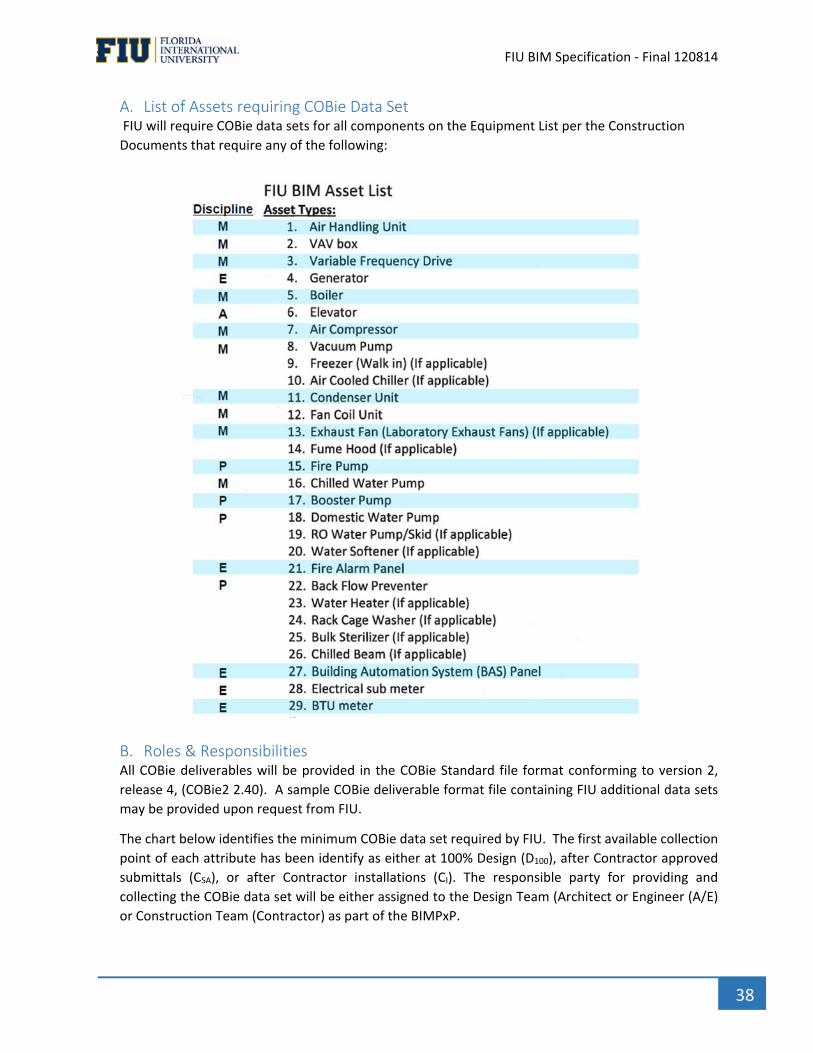
` FIU BIM Specification ‐ Final 120814
38
A. List of Assets requiring COBie Data Set FIU will require COBie data sets for all components on the Equipment List per the Construction
Documents that require any of the following:
B. Roles & Responsibilities All COBie deliverables will be provided in the COBie Standard file format conforming to version 2,
release 4, (COBie2 2.40). A sample COBie deliverable format file containing FIU additional data sets
may be provided upon request from FIU.
The chart below identifies the minimum COBie data set required by FIU. The first available collection
point of each attribute has been identify as either at 100% Design (D100), after Contractor approved
submittals (CSA), or after Contractor installations (CI). The responsible party for providing and
collecting the COBie data set will be either assigned to the Design Team (Architect or Engineer (A/E)
or Construction Team (Contractor) as part of the BIMPxP.

` FIU BIM Specification ‐ Final 120814
39
In the case where FIU may request additional sets of data to be provided, it will then be the
responsibility of the Design & Construction Teams to add those attribute names to the chart, and
identify when first available and who is responsible for collection. A revised chart should become part
of the approved BIMPxP plan.
A/E Holds the Design Team Prime Contract
Contractor Holds the Construction Team Prime Contract
D100 100% design stage/CD
CSA Contractor Approved submittals
CI Contractor Installation
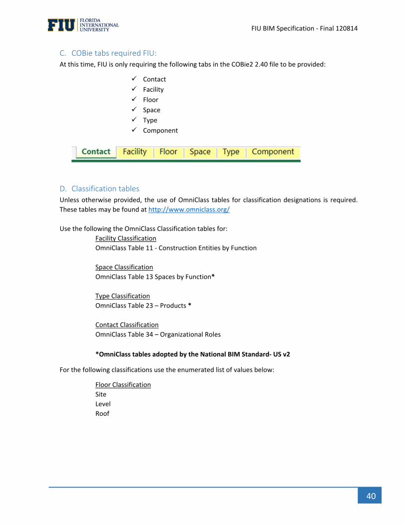
` FIU BIM Specification ‐ Final 120814
40
C. COBie tabs required FIU: At this time, FIU is only requiring the following tabs in the COBie2 2.40 file to be provided:
Contact
Facility
Floor
Space
Type
Component
D. Classification tables Unless otherwise provided, the use of OmniClass tables for classification designations is required.
These tables may be found at http://www.omniclass.org/
Use the following the OmniClass Classification tables for:
Facility Classification
OmniClass Table 11 ‐ Construction Entities by Function
Space Classification
OmniClass Table 13 Spaces by Function*
Type Classification
OmniClass Table 23 – Products *
Contact Classification
OmniClass Table 34 – Organizational Roles
*OmniClass tables adopted by the National BIM Standard‐ US v2
For the following classifications use the enumerated list of values below:
Floor Classification
Site
Level
Roof
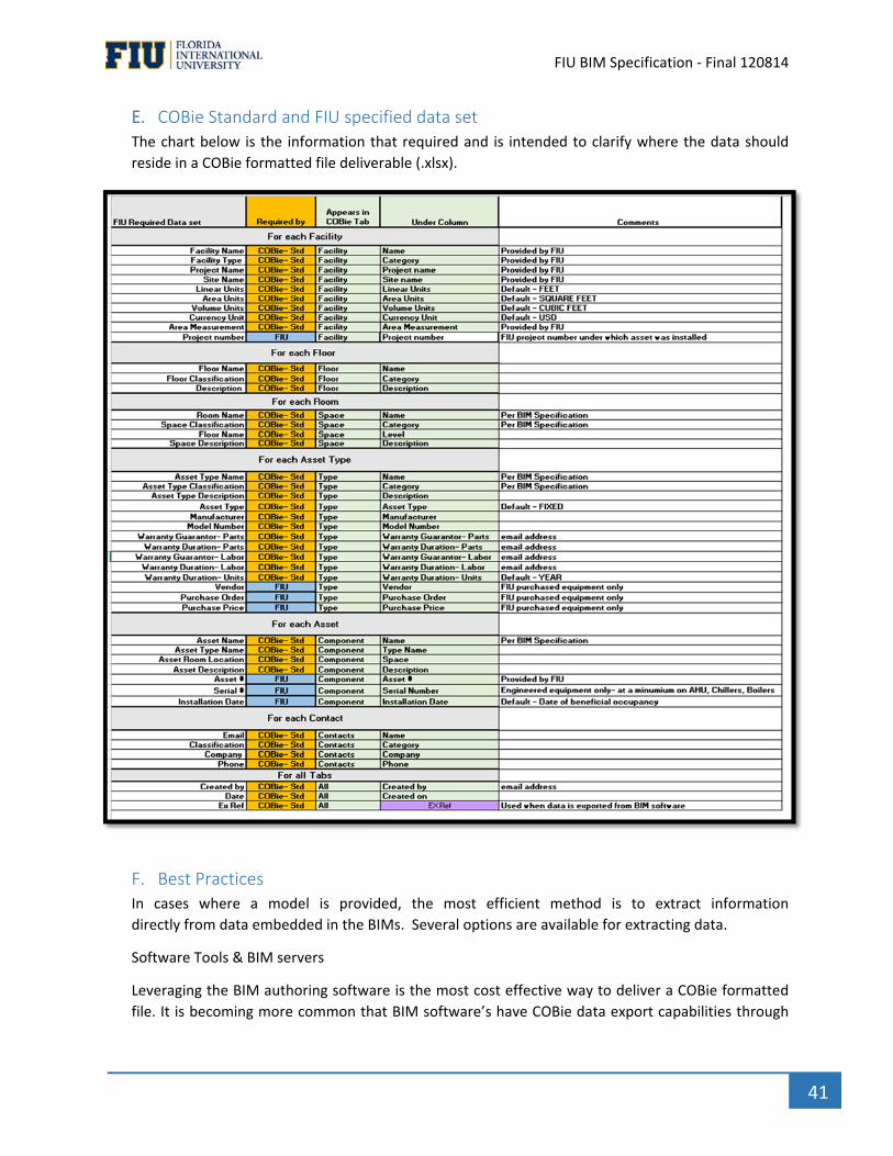
` FIU BIM Specification ‐ Final 120814
41
E. COBie Standard and FIU specified data set The chart below is the information that required and is intended to clarify where the data should
reside in a COBie formatted file deliverable (.xlsx).
F. Best Practices In cases where a model is provided, the most efficient method is to extract information
directly from data embedded in the BIMs. Several options are available for extracting data.
Software Tools & BIM servers
Leveraging the BIM authoring software is the most cost effective way to deliver a COBie formatted
file. It is becoming more common that BIM software’s have COBie data export capabilities through
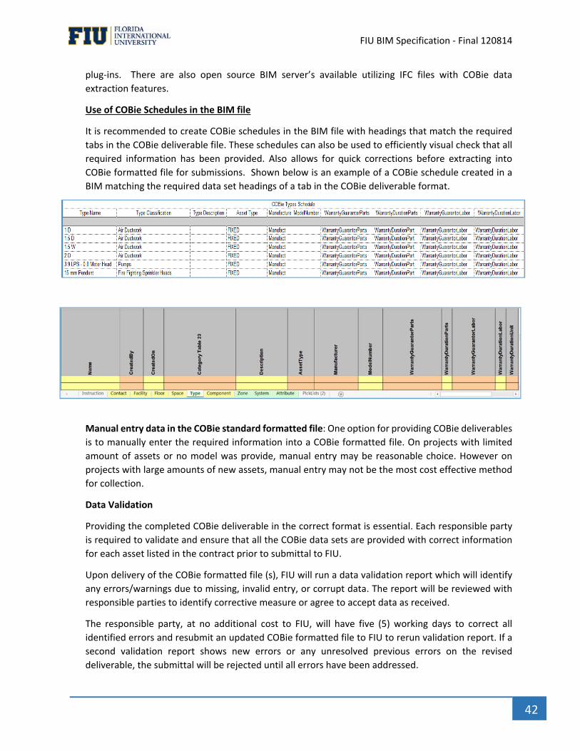
` FIU BIM Specification ‐ Final 120814
42
plug‐ins. There are also open source BIM server’s available utilizing IFC files with COBie data
extraction features.
Use of COBie Schedules in the BIM file
It is recommended to create COBie schedules in the BIM file with headings that match the required
tabs in the COBie deliverable file. These schedules can also be used to efficiently visual check that all
required information has been provided. Also allows for quick corrections before extracting into
COBie formatted file for submissions. Shown below is an example of a COBie schedule created in a
BIM matching the required data set headings of a tab in the COBie deliverable format.
Manual entry data in the COBie standard formatted file: One option for providing COBie deliverables
is to manually enter the required information into a COBie formatted file. On projects with limited
amount of assets or no model was provide, manual entry may be reasonable choice. However on
projects with large amounts of new assets, manual entry may not be the most cost effective method
for collection.
Data Validation
Providing the completed COBie deliverable in the correct format is essential. Each responsible party
is required to validate and ensure that all the COBie data sets are provided with correct information
for each asset listed in the contract prior to submittal to FIU.
Upon delivery of the COBie formatted file (s), FIU will run a data validation report which will identify
any errors/warnings due to missing, invalid entry, or corrupt data. The report will be reviewed with
responsible parties to identify corrective measure or agree to accept data as received.
The responsible party, at no additional cost to FIU, will have five (5) working days to correct all
identified errors and resubmit an updated COBie formatted file to FIU to rerun validation report. If a
second validation report shows new errors or any unresolved previous errors on the revised
deliverable, the submittal will be rejected until all errors have been addressed.

` FIU BIM Specification ‐ Final 120814
43
G. COBie Progression Schedule (CPS) FIU will implement a Transition to Operations approach to allow the facility management team time
to prepare for the new assets by requiring progressive delivery of COBie data sets based on Project
Phases. In some cases, there could be multiple deliverables within one project phase. The complete
schedule of deliverables is to be stated in the BIMPxP.
The first COBie file deliverable will be from the Design Team with a data set using the 100% design
model provided in the contract documents or created from 2D contract documents. This first
deliverable will be due with 30 days of Construction Documents submittal.
For the assets listed in the contract as requiring COBie data sets, the following information is to be
delivered in a COBie2 2.40 formatted file:

` FIU BIM Specification ‐ Final 120814
44
The second COBie file deliverable will be during submittal approval (Csa) phase, also provided by
design team. This deliverable should be stated in the BIMPxP as it may be done incrementally or at
one time after all approvals have been completed and models have been updated with approved
assets. For the assets listed in the contract as requiring COBie data sets, the following information is
to be delivered in a COBie formatted file:
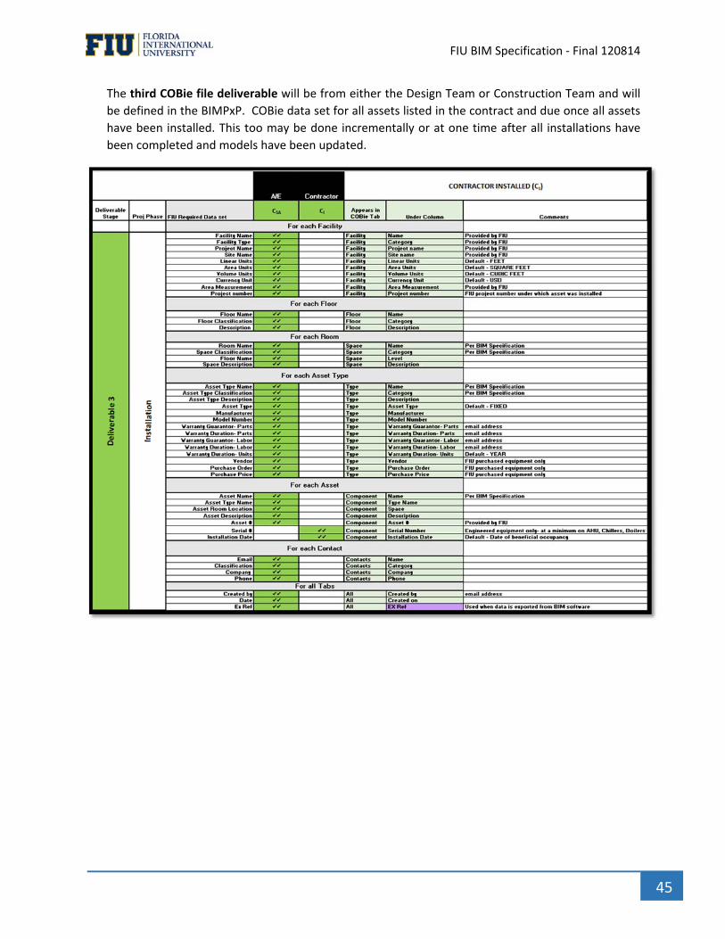
` FIU BIM Specification ‐ Final 120814
45
The third COBie file deliverable will be from either the Design Team or Construction Team and will
be defined in the BIMPxP. COBie data set for all assets listed in the contract and due once all assets
have been installed. This too may be done incrementally or at one time after all installations have
been completed and models have been updated.

` FIU BIM Specification ‐ Final 120814
46
The final COBie file deliverable will be from Design Team or Construction Team as defined in the
BIMPxP that represents the As‐Built models and will be a complete COBie data set for all assets listed
in the contract, and due same time as As‐Built models.
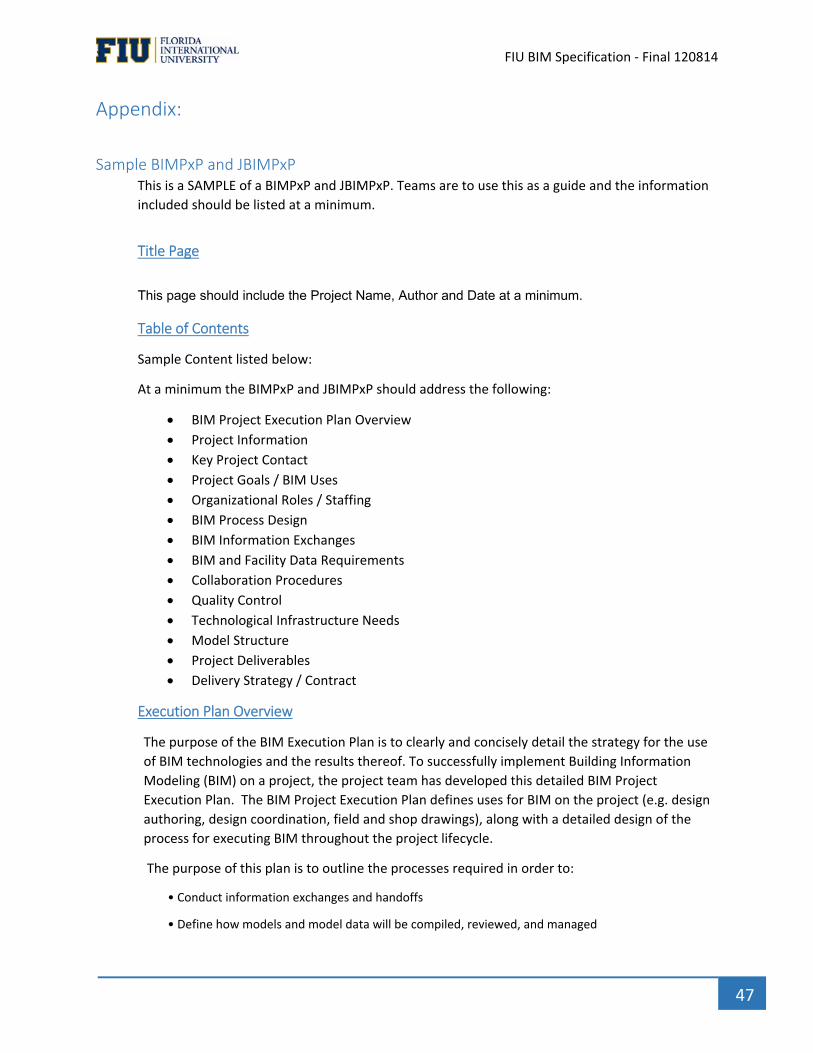
` FIU BIM Specification ‐ Final 120814
47
Appendix:
Sample BIMPxP and JBIMPxP This is a SAMPLE of a BIMPxP and JBIMPxP. Teams are to use this as a guide and the information
included should be listed at a minimum.
Title Page
This page should include the Project Name, Author and Date at a minimum. Table of Contents
Sample Content listed below:
At a minimum the BIMPxP and JBIMPxP should address the following:
BIM Project Execution Plan Overview
Project Information
Key Project Contact
Project Goals / BIM Uses
Organizational Roles / Staffing
BIM Process Design
BIM Information Exchanges
BIM and Facility Data Requirements
Collaboration Procedures
Quality Control
Technological Infrastructure Needs
Model Structure
Project Deliverables
Delivery Strategy / Contract
Execution Plan Overview
The purpose of the BIM Execution Plan is to clearly and concisely detail the strategy for the use
of BIM technologies and the results thereof. To successfully implement Building Information
Modeling (BIM) on a project, the project team has developed this detailed BIM Project
Execution Plan. The BIM Project Execution Plan defines uses for BIM on the project (e.g. design
authoring, design coordination, field and shop drawings), along with a detailed design of the
process for executing BIM throughout the project lifecycle.
The purpose of this plan is to outline the processes required in order to:
• Conduct information exchanges and handoffs
• Define how models and model data will be compiled, reviewed, and managed
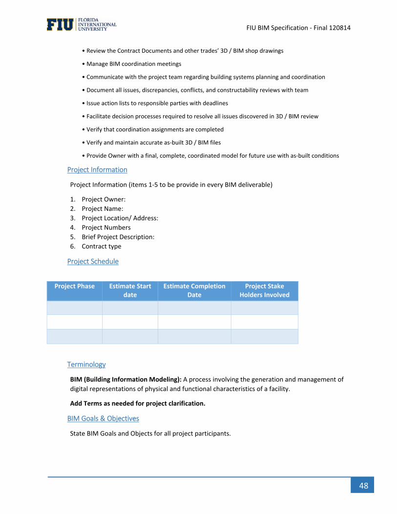
` FIU BIM Specification ‐ Final 120814
48
• Review the Contract Documents and other trades’ 3D / BIM shop drawings
• Manage BIM coordination meetings
• Communicate with the project team regarding building systems planning and coordination
• Document all issues, discrepancies, conflicts, and constructability reviews with team
• Issue action lists to responsible parties with deadlines
• Facilitate decision processes required to resolve all issues discovered in 3D / BIM review
• Verify that coordination assignments are completed
• Verify and maintain accurate as‐built 3D / BIM files
• Provide Owner with a final, complete, coordinated model for future use with as‐built conditions
Project Information
Project Information (items 1‐5 to be provide in every BIM deliverable)
1. Project Owner:
2. Project Name:
3. Project Location/ Address:
4. Project Numbers
5. Brief Project Description:
6. Contract type
Project Schedule
Project Phase Estimate Start date
Estimate Completion Date
Project Stake Holders Involved
Terminology
BIM (Building Information Modeling): A process involving the generation and management of
digital representations of physical and functional characteristics of a facility.
Add Terms as needed for project clarification.
BIM Goals & Objectives
State BIM Goals and Objects for all project participants.
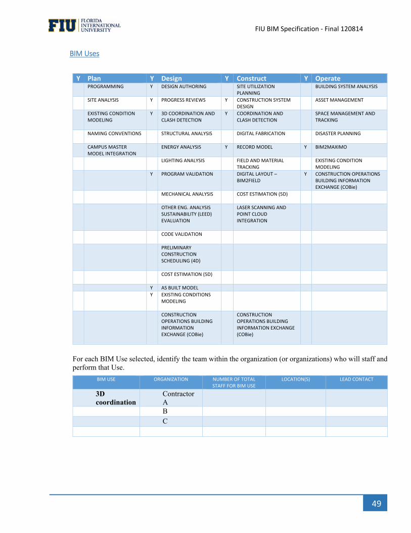
` FIU BIM Specification ‐ Final 120814
49
BIM Uses
Y Plan Y Design Y Construct Y Operate PROGRAMMING Y DESIGN AUTHORING SITE UTILIZATION
PLANNING BUILDING SYSTEM ANALYSIS
SITE ANALYSIS Y PROGRESS REVIEWS Y CONSTRUCTION SYSTEM DESIGN
ASSET MANAGEMENT
EXISTING CONDITION MODELING
Y 3D COORDINATION AND CLASH DETECTION
Y COORDINATION AND CLASH DETECTION
SPACE MANAGEMENT AND TRACKING
NAMING CONVENTIONS STRUCTURAL ANALYSIS
DIGITAL FABRICATION DISASTER PLANNING
CAMPUS MASTER MODEL INTEGRATION
ENERGY ANALYSIS
Y RECORD MODEL Y BIM2MAXIMO
LIGHTING ANALYSIS FIELD AND MATERIAL TRACKING
EXISTING CONDITION MODELING
Y PROGRAM VALIDATION
DIGITAL LAYOUT –BIM2FIELD
Y CONSTRUCTION OPERATIONSBUILDING INFORMATION EXCHANGE (COBie)
MECHANICAL ANALYSIS
COST ESTIMATION (5D)
OTHER ENG. ANALYSISSUSTAINABILITY (LEED) EVALUATION
LASER SCANNING AND POINT CLOUD INTEGRATION
CODE VALIDATION
PRELIMINARY CONSTRUCTION SCHEDULING (4D)
COST ESTIMATION (5D)
Y AS BUILT MODEL
Y EXISTING CONDITIONS MODELING
CONSTRUCTION OPERATIONS BUILDING INFORMATION EXCHANGE (COBie)
CONSTRUCTION OPERATIONS BUILDING INFORMATION EXCHANGE (COBie)
For each BIM Use selected, identify the team within the organization (or organizations) who will staff and perform that Use.
BIM USE ORGANIZATION NUMBER OF TOTAL STAFF FOR BIM USE
LOCATION(S) LEAD CONTACT
3D coordination
Contractor A
B
C
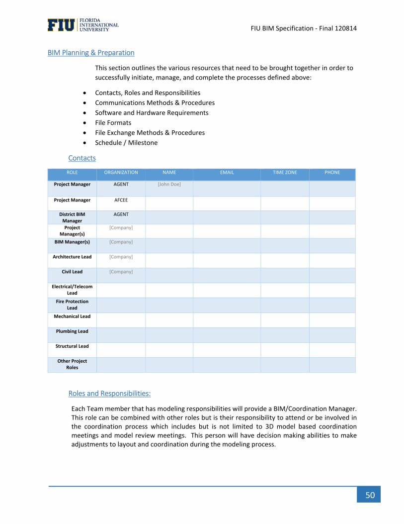
` FIU BIM Specification ‐ Final 120814
50
BIM Planning & Preparation
This section outlines the various resources that need to be brought together in order to
successfully initiate, manage, and complete the processes defined above:
Contacts, Roles and Responsibilities
Communications Methods & Procedures
Software and Hardware Requirements
File Formats
File Exchange Methods & Procedures
Schedule / Milestone
Contacts
ROLE ORGANIZATION NAME EMAIL TIME ZONE PHONE
Project Manager AGENT [John Doe]
Project Manager AFCEE
District BIM Manager
AGENT
Project Manager(s)
[Company]
BIM Manager(s) [Company]
Architecture Lead [Company]
Civil Lead [Company]
Electrical/Telecom Lead
Fire Protection Lead
Mechanical Lead
Plumbing Lead
Structural Lead
Other Project Roles
Roles and Responsibilities:
Each Team member that has modeling responsibilities will provide a BIM/Coordination Manager. This role can be combined with other roles but is their responsibility to attend or be involved in the coordination process which includes but is not limited to 3D model based coordination meetings and model review meetings. This person will have decision making abilities to make adjustments to layout and coordination during the modeling process.

` FIU BIM Specification ‐ Final 120814
51
Role Responsibility
Design / Construction BIM Manager
BIM Coordinator
Model Manager
Communications Methods & Procedures:
Model managers shall be the point of contact for all model coordination. File sharing shall be
accomplished via the use of an online file‐transfer site (XX) to allow access and sharing of all
necessary information, documents, and models. (XX) will setup and grant all of the consultants’
access rights.
Modeling
Origin Monument, Location, and Base
(xx) will provide (XX) with the origin monument, grids and levels. The starting origin shall be
the Location with Project Base Point (PBP) aligned. The column grid starting point of A‐1 will
align with the starting origin mentioned.
Units shall be Imperial units. Grid intersection A‐1 of the structural grid found on sheet ( ) and elevation 0’‐0” (T.O.S. GROUND FLOOR (+16’‐6” NGVD)) shall be used as the origin point for all models, and an object named “ORIGIN MONUMENT,” and placed on a unique layer named “ORIGIN MONUMENT”, 12”x12” in plan and 100 feet high shall be inserted at the origin point of all files in accordance with the below example diagram.
Scope of Work & Level of Development
Discipline Model LOD Modeler Responsible Party for QA/QC Notes
Architecture
Structural
Mechanical
Electrical
Plumbing
Fire Protection
Furnishing (appliance)
Furnishing (casework)
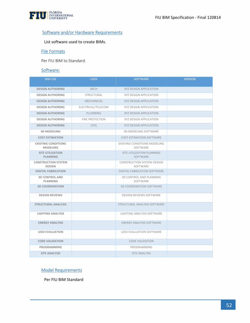
` FIU BIM Specification ‐ Final 120814
52
Software and/or Hardware Requirements
List software used to create BIMs.
File Formats
Per FIU BIM to Standard.
Software:
BIM USE USER SOFTWARE VERSION
DESIGN AUTHORING ARCH XYZ DESIGN APPLICATION
DESIGN AUTHORING STRUCTURAL XYZ DESIGN APPLICATION DESIGN AUTHORING MECHANICAL XYZ DESIGN APPLICATION DESIGN AUTHORING ELECTRICAL/TELECOM XYZ DESIGN APPLICATION DESIGN AUTHORING PLUMBING XYZ DESIGN APPLICATION DESIGN AUTHORING FIRE PROTECTION XYZ DESIGN APPLICATION DESIGN AUTHORING CIVIL XYZ DESIGN APPLICATION
4D MODELING 4D MODELING SOFTWARE
COST ESTIMATION COST ESTIMATION SOFTWARE
EXISTING CONDITIONS MODELING
EXISTING CONDITIONS MODELING SOFTWARE
SITE UTILIZATION PLANNING
SITE UTILIZATION PLANNING SOFTWARE
CONSTRUCTION SYSTEM DESIGN
CONSTRUCTION SYSTEM DESIGN SOFTWARE
DIGITAL FABRICATION DIGITAL FABRICATION SOFTWARE
3D CONTROL AND PLANNING
3D CONTROL AND PLANNING SOFTWARE
3D COORDINATION 3D COORDINATION SOFTWARE
DESIGN REVIEWS DESIGN REVIEWS SOFTWARE
STRUCTURAL ANALYSIS STRUCTURAL ANALYSIS SOFTWARE
LIGHTING ANALYSIS LIGHTING ANALYSIS SOFTWARE
ENERGY ANALYSIS ENERGY ANALYSIS SOFTWARE
LEED EVALUATION LEED EVALUATION SOFTWARE
CODE VALIDATION CODE VALIDATION
PROGRAMMING PROGRAMMING
SITE ANALYSIS SITE ANALYSIS
Model Requirements
Per FIU BIM Standard
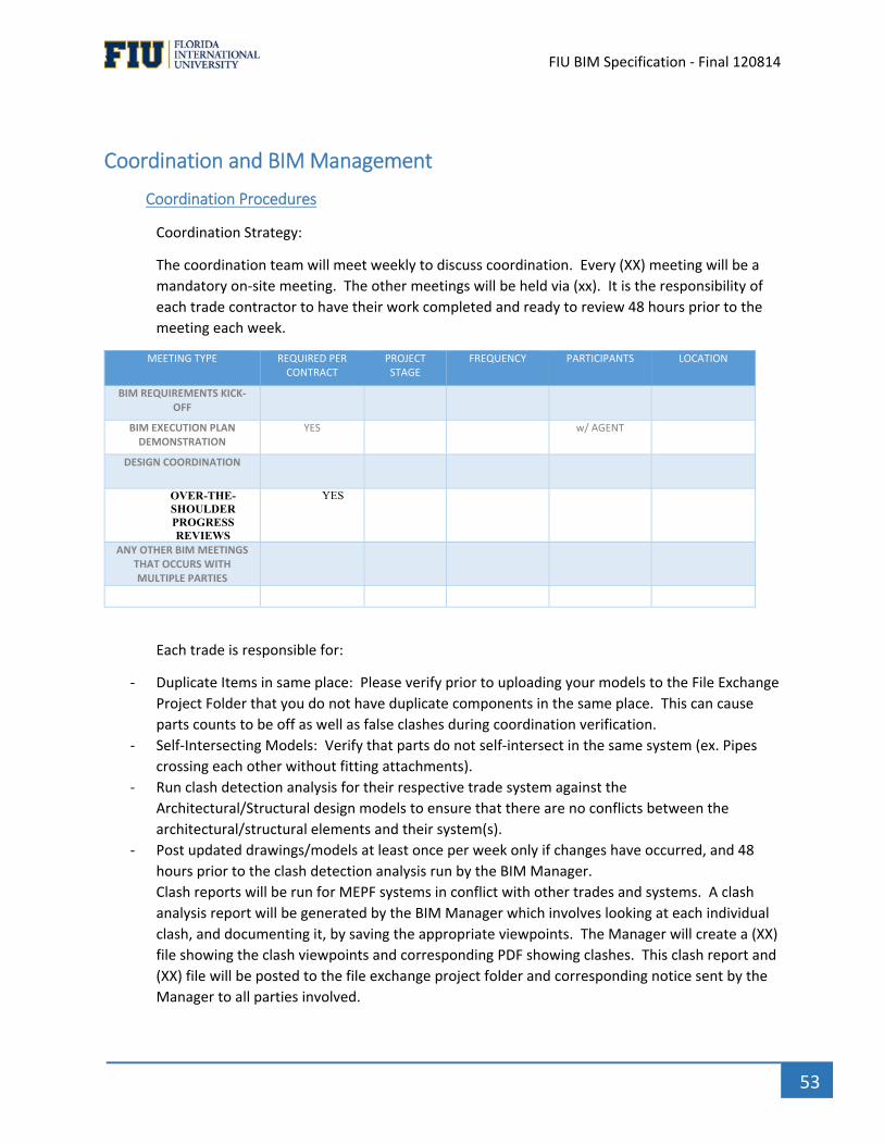
` FIU BIM Specification ‐ Final 120814
53
Coordination and BIM Management
Coordination Procedures
Coordination Strategy:
The coordination team will meet weekly to discuss coordination. Every (XX) meeting will be a
mandatory on‐site meeting. The other meetings will be held via (xx). It is the responsibility of
each trade contractor to have their work completed and ready to review 48 hours prior to the
meeting each week.
MEETING TYPE REQUIRED PER CONTRACT
PROJECT STAGE
FREQUENCY PARTICIPANTS LOCATION
BIM REQUIREMENTS KICK‐OFF
BIM EXECUTION PLAN DEMONSTRATION
YES w/ AGENT
DESIGN COORDINATION
OVER-THE-SHOULDER PROGRESS REVIEWS
YES
ANY OTHER BIM MEETINGS THAT OCCURS WITH MULTIPLE PARTIES
Each trade is responsible for:
‐ Duplicate Items in same place: Please verify prior to uploading your models to the File Exchange
Project Folder that you do not have duplicate components in the same place. This can cause
parts counts to be off as well as false clashes during coordination verification.
‐ Self‐Intersecting Models: Verify that parts do not self‐intersect in the same system (ex. Pipes
crossing each other without fitting attachments).
‐ Run clash detection analysis for their respective trade system against the
Architectural/Structural design models to ensure that there are no conflicts between the
architectural/structural elements and their system(s).
‐ Post updated drawings/models at least once per week only if changes have occurred, and 48
hours prior to the clash detection analysis run by the BIM Manager.
Clash reports will be run for MEPF systems in conflict with other trades and systems. A clash
analysis report will be generated by the BIM Manager which involves looking at each individual
clash, and documenting it, by saving the appropriate viewpoints. The Manager will create a (XX)
file showing the clash viewpoints and corresponding PDF showing clashes. This clash report and
(XX) file will be posted to the file exchange project folder and corresponding notice sent by the
Manager to all parties involved.

` FIU BIM Specification ‐ Final 120814
54
‐ Review the clash detection report generated by the BIM Manager before the weekly meeting
and arrive at the meeting prepared to address the unresolved clashes in a constructive manner.
‐ Each trade is required to collaborate with each other trade through email, telephone and in
person to resolve basic clashes outside of the weekly coordination meetings. A report will be
generated by each trade documenting the resolutions of basic clashes. It is expected that the
weekly coordination meetings are held to address difficult areas that are not able to be
coordinated between the multiple trades themselves. At these meetings, the resolution will be
mutually agreed upon by involved parties, and a trade will be assigned as having to “move.”
This assigned trade will adjust the respective model and repost it for the following weeks
meeting. All trades are responsible to update and post the changes agreed upon prior to the
following coordination meeting.
File Exchange Methods & Procedures
File exchange will be conducted via (XX). Each consultant will receive an invitation to access the
project folder. (XX) will be responsible for maintaining and integrating all of the 3D trades’
models into a single consolidated master model. This master model will be available to all
parties for review. The master model will be updated weekly and accessible for download from
(XXX).
Each party will be required to notify all affected trades on the contact list when a new file is
uploaded. The sooner that people have access to the updated files, the better coordinated all of
the trades can be. An effort will be made to automate the notification system directly from the
Exchange Server being used.
Preliminary BIMs will be provided by ( ) at the start of the project and will include Base,
Architectural, and Structural models. This will serve as a framework for MEP trades to begin
modeling their systems.
(XX) will provide an updated (xxx) coordination model weekly showing clashes and notations.
Each party is responsible for reviewing the saved reports and all notes each week as the new
document is published. Even if said clashes or notes are not resolved before they have been
assigned, please be prepared to discuss the clashes and notes in the following coordination
meetings.
Once the updated coordination model is released, all previous models should be archived,
considered previous revisions and no longer valid to model from.
(XX) will combine and review the newly updated files and will re‐check for clashes and verify
changes. This will become the new basis for the next master coordination model and will
include any new viewpoints, notes, redlines and clashes.
The weekly coordination meetings will require all parties inclusive of all sub‐contractors as well
as the (XX)’ BIM Manager and Project Team Member to be available by both telephone and
webcast or in person if applicable.
This process will be repeated and coordination meetings will continue until all members sign off
on the final design and construction procedures.
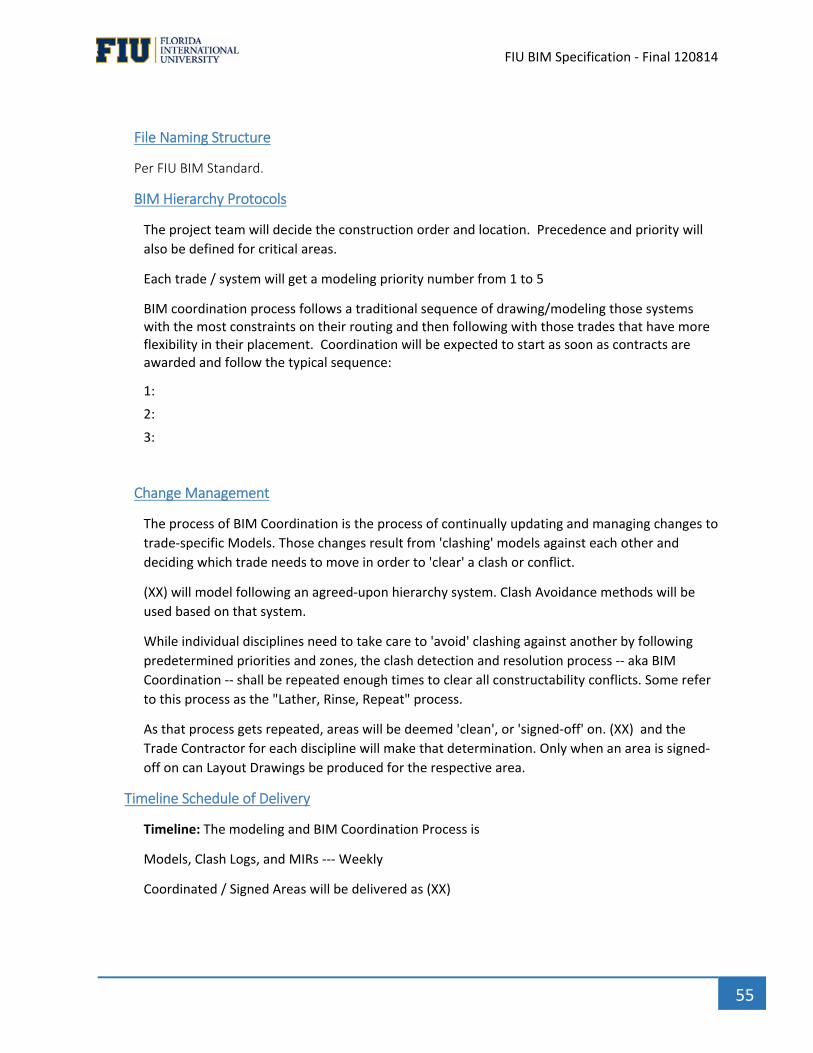
` FIU BIM Specification ‐ Final 120814
55
File Naming Structure
Per FIU BIM Standard.
BIM Hierarchy Protocols
The project team will decide the construction order and location. Precedence and priority will
also be defined for critical areas.
Each trade / system will get a modeling priority number from 1 to 5
BIM coordination process follows a traditional sequence of drawing/modeling those systems with the most constraints on their routing and then following with those trades that have more flexibility in their placement. Coordination will be expected to start as soon as contracts are awarded and follow the typical sequence:
1:
2:
3:
Change Management
The process of BIM Coordination is the process of continually updating and managing changes to
trade‐specific Models. Those changes result from 'clashing' models against each other and
deciding which trade needs to move in order to 'clear' a clash or conflict.
(XX) will model following an agreed‐upon hierarchy system. Clash Avoidance methods will be
used based on that system.
While individual disciplines need to take care to 'avoid' clashing against another by following
predetermined priorities and zones, the clash detection and resolution process ‐‐ aka BIM
Coordination ‐‐ shall be repeated enough times to clear all constructability conflicts. Some refer
to this process as the "Lather, Rinse, Repeat" process.
As that process gets repeated, areas will be deemed 'clean', or 'signed‐off' on. (XX) and the
Trade Contractor for each discipline will make that determination. Only when an area is signed‐
off on can Layout Drawings be produced for the respective area.
Timeline Schedule of Delivery
Timeline: The modeling and BIM Coordination Process is
Models, Clash Logs, and MIRs ‐‐‐ Weekly
Coordinated / Signed Areas will be delivered as (XX)

` FIU BIM Specification ‐ Final 120814
56
Discipline Project Phase Modeling Start Date
Modeling End Date
Coordination Start Date
Coordination End Date
Project Stakeholders
Architecture
Structure
Electrical
Mechanical
Plumbing
Fire Protection
Civil / Site
Shop & Field Implementation & Execution
(XXX) will prepare architectural and structural layouts.
The official Contract Documents are still the traditional Construction Documents along with the
Specifications and Qualifications – Subcontractors are not relieved from verifying compliance
with CDs.
Final Submission
(XYZ) will deliver final BIMs per trade/or discipline in (XYZ) format, and a federated BIM in (XYZ)
format to FIU.
BIM SUBMITTAL ITEM STAGE FORMAT NOTES
QA/QC reports – Model Standards Check Report
QA/QC reports - Interference Report (2.4.2)
IFC file Native files Visualization Model (Navigator, Navisworks, 3dPDF, Google Earth, etc.)
List of all submitted files (Excel spreadsheet preferred)
COBie Final Design Submittal Construction Submittals As-Built Submittal (3.6) [Other BIM Deliverables]
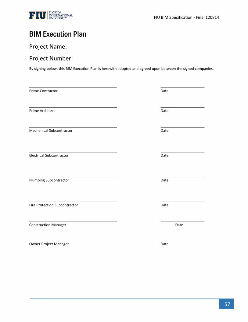
` FIU BIM Specification ‐ Final 120814
57
BIM Execution Plan
Project Name:
Project Number:
By signing below, this BIM Execution Plan is herewith adopted and agreed upon between the signed companies.
Prime Contractor Date Prime Architect Date Mechanical Subcontractor Date Electrical Subcontractor Date Plumbing Subcontractor Date Fire Protection Subcontractor Date Construction Manager Date
Owner Project Manager Date
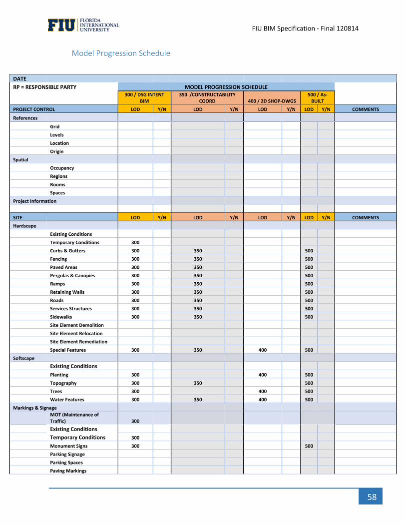
` FIU BIM Specification ‐ Final 120814
58
Model Progression Schedule
DATE
RP = RESPONSIBLE PARTY MODEL PROGRESSION SCHEDULE 300 / DSG INTENT
BIM 350 /CONSTRUCTABILITY
COORD 400 / 2D SHOP‐DWGS 500 / As‐BUILT
PROJECT CONTROL LOD Y/N LOD Y/N LOD Y/N LOD Y/N COMMENTS
References
Grid
Levels
Location
Origin
Spatial
Occupancy
Regions
Rooms
Spaces
Project Information
SITE LOD Y/N LOD Y/N LOD Y/N LOD Y/N COMMENTS
Hardscape
Existing Conditions
Temporary Conditions 300
Curbs & Gutters 300 350 500
Fencing 300 350 500
Paved Areas 300 350 500
Pergolas & Canopies 300 350 500
Ramps 300 350 500
Retaining Walls 300 350 500
Roads 300 350 500
Services Structures 300 350 500
Sidewalks 300 350 500
Site Element Demolition
Site Element Relocation
Site Element Remediation
Special Features 300 350 400 500
Softscape
Existing Conditions
Planting 300 400 500
Topography 300 350 500
Trees 300 400 500
Water Features 300 350 400 500
Markings & Signage
MOT (Maintenance of Traffic) 300
Existing Conditions
Temporary Conditions 300
Monument Signs 300 500
Parking Signage
Parking Spaces
Paving Markings
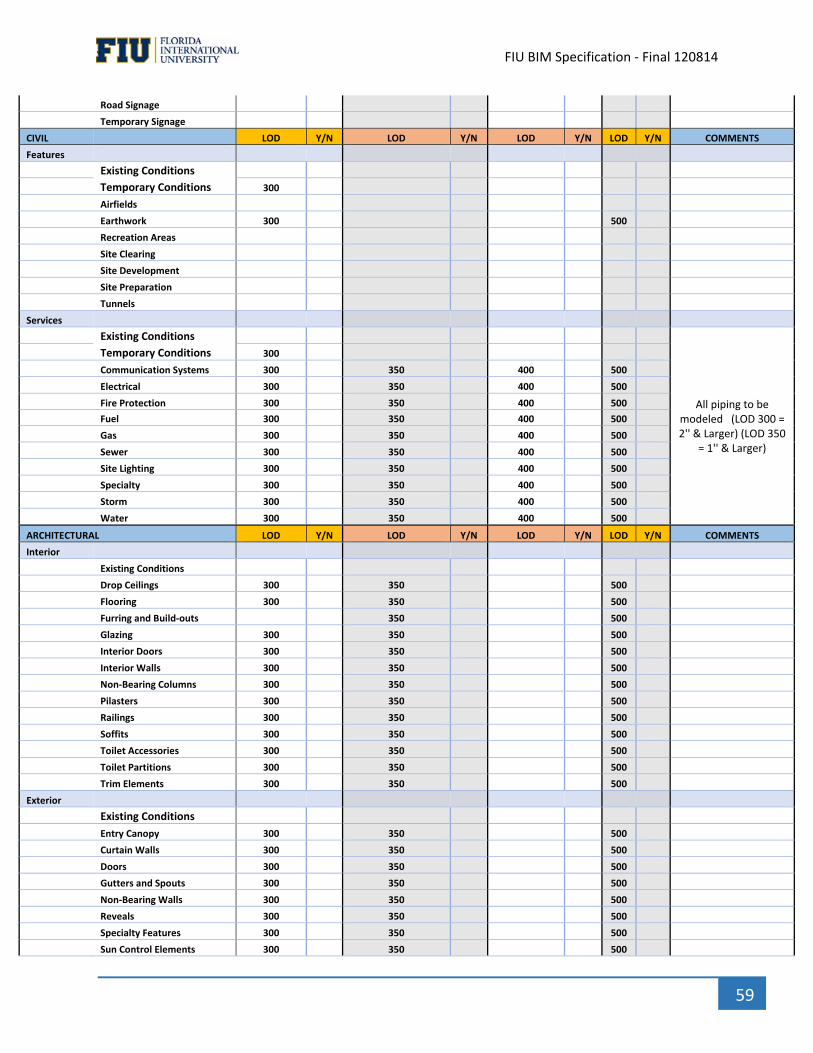
` FIU BIM Specification ‐ Final 120814
59
Road Signage
Temporary Signage
CIVIL LOD Y/N LOD Y/N LOD Y/N LOD Y/N COMMENTS
Features
Existing Conditions
Temporary Conditions 300
Airfields
Earthwork 300 500
Recreation Areas
Site Clearing
Site Development
Site Preparation
Tunnels
Services
Existing Conditions
All piping to be modeled (LOD 300 = 2'' & Larger) (LOD 350
= 1'' & Larger)
Temporary Conditions 300
Communication Systems 300 350 400 500
Electrical 300 350 400 500
Fire Protection 300 350 400 500
Fuel 300 350 400 500
Gas 300 350 400 500
Sewer 300 350 400 500
Site Lighting 300 350 400 500
Specialty 300 350 400 500
Storm 300 350 400 500
Water 300 350 400 500
ARCHITECTURAL LOD Y/N LOD Y/N LOD Y/N LOD Y/N COMMENTS
Interior
Existing Conditions
Drop Ceilings 300 350 500
Flooring 300 350 500
Furring and Build‐outs 350 500
Glazing 300 350 500
Interior Doors 300 350 500
Interior Walls 300 350 500
Non‐Bearing Columns 300 350 500
Pilasters 300 350 500
Railings 300 350 500
Soffits 300 350 500
Toilet Accessories 300 350 500
Toilet Partitions 300 350 500
Trim Elements 300 350 500
Exterior
Existing Conditions
Entry Canopy 300 350 500
Curtain Walls 300 350 500
Doors 300 350 500
Gutters and Spouts 300 350 500
Non‐Bearing Walls 300 350 500
Reveals 300 350 500
Specialty Features 300 350 500
Sun Control Elements 300 350 500
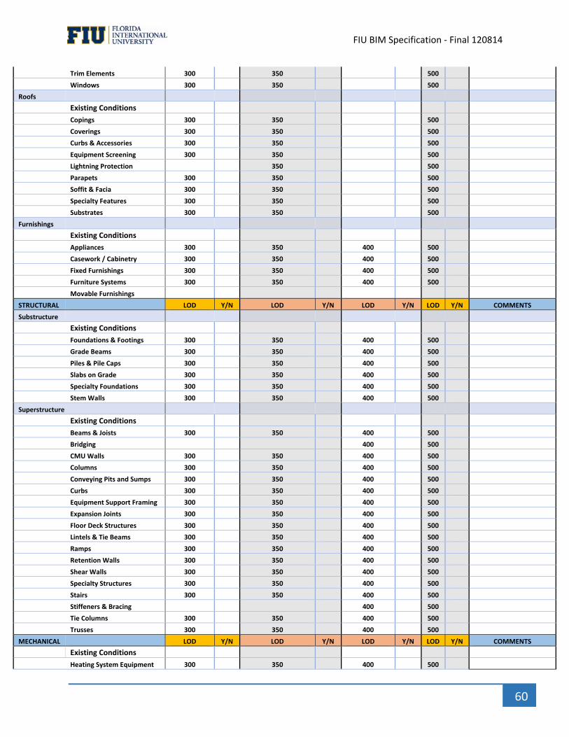
` FIU BIM Specification ‐ Final 120814
60
Trim Elements 300 350 500
Windows 300 350 500
Roofs
Existing Conditions
Copings 300 350 500
Coverings 300 350 500
Curbs & Accessories 300 350 500
Equipment Screening 300 350 500
Lightning Protection 350 500
Parapets 300 350 500
Soffit & Facia 300 350 500
Specialty Features 300 350 500
Substrates 300 350 500
Furnishings
Existing Conditions
Appliances 300 350 400 500
Casework / Cabinetry 300 350 400 500
Fixed Furnishings 300 350 400 500
Furniture Systems 300 350 400 500
Movable Furnishings
STRUCTURAL LOD Y/N LOD Y/N LOD Y/N LOD Y/N COMMENTS
Substructure
Existing Conditions
Foundations & Footings 300 350 400 500
Grade Beams 300 350 400 500
Piles & Pile Caps 300 350 400 500
Slabs on Grade 300 350 400 500
Specialty Foundations 300 350 400 500
Stem Walls 300 350 400 500
Superstructure
Existing Conditions
Beams & Joists 300 350 400 500
Bridging 400 500
CMU Walls 300 350 400 500
Columns 300 350 400 500
Conveying Pits and Sumps 300 350 400 500
Curbs 300 350 400 500
Equipment Support Framing 300 350 400 500
Expansion Joints 300 350 400 500
Floor Deck Structures 300 350 400 500
Lintels & Tie Beams 300 350 400 500
Ramps 300 350 400 500
Retention Walls 300 350 400 500
Shear Walls 300 350 400 500
Specialty Structures 300 350 400 500
Stairs 300 350 400 500
Stiffeners & Bracing 400 500
Tie Columns 300 350 400 500
Trusses 300 350 400 500
MECHANICAL LOD Y/N LOD Y/N LOD Y/N LOD Y/N COMMENTS
Existing Conditions
Heating System Equipment 300 350 400 500
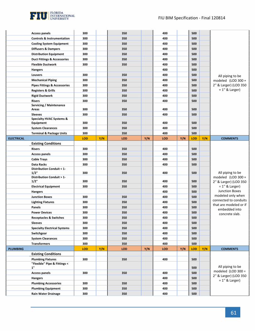
` FIU BIM Specification ‐ Final 120814
61
Access panels 300 350 400 500
All piping to be modeled (LOD 300 = 2'' & Larger) (LOD 350
= 1'' & Larger)
Controls & Instrumentation 300 350 400 500
Cooling System Equipment 300 350 400 500
Diffusers & Dampers 300 350 400 500
Distribution Equipment 300 350 400 500
Duct Fittings & Accessories 300 350 400 500
Flexible Ductwork 300 350 400 500
Hangers 400 500
Louvers 300 350 400 500
Mechanical Piping 300 350 400 500
Pipes Fittings & Accessories 300 350 400 500
Registers & Grills 300 350 400 500
Rigid Ductwork 300 350 400 500
Risers 300 350 400 500
Servicing / Maintenance Areas 300 350 400 500
Sleeves 300 350 400 500
Specialty HVAC Systems & Equipment 300 350 400 500
System Clearances 300 350 400 500
Terminal & Package Units 300 350 400 500
ELECTRICAL LOD Y/N LOD Y/N LOD Y/N LOD Y/N COMMENTS
Existing Conditions
All piping to be modeled (LOD 300 = 2'' & Larger) (LOD 350
= 1'' & Larger) Junction Boxes
modeled only when connected to conduits that are modeled or if
embedded into concrete slab.
Risers 300 350 400 500
Access panels 300 350 400 500
Cable Trays 300 350 400 500
Data Racks 300 350 400 500
Distribution Conduit < 1‐1/2" 300 350 400 500
Distribution Conduit > 1‐1/2" 300 350 400 500
Electrical Equipment 300 350 400 500
Hangers 400 500
Junction Boxes 300 350 400 500
Lighting Fixtures 300 350 400 500
Panels 300 350 400 500
Power Devices 300 350 400 500
Receptacles & Switches 300 350 400 500
Sleeves 300 350 400 500
Specialty Electrical Systems 300 350 400 500
Switchgear 300 350 400 500
System Clearances 300 350 400 500
Transformers 300 350 400 500
PLUMBING LOD Y/N LOD Y/N LOD Y/N LOD Y/N COMMENTS
Existing Conditions
All piping to be modeled (LOD 300 = 2'' & Larger) (LOD 350
= 1'' & Larger)
Plumbing Fixtures 300 350 400 500
"Flexible" Pipe & Fittings < 1" 500
Access panels 300 350 400 500
Hangers 400 500
Plumbing Accessories 300 350 400 500
Plumbing Equipment 300 350 400 500
Rain Water Drainage 300 350 400 500

` FIU BIM Specification ‐ Final 120814
62
Rigid Piping & Fittings 300 350 400 500
Risers 300 350 400 500
Sleeves 300 350 400 500
Specialty Plumbing Systems 300 350 400 500
System Clearances 300 350 400 500
FIRE PROTECTION LOD Y/N LOD Y/N LOD Y/N LOD Y/N COMMENTS
Existing Conditions
All piping to be modeled (LOD 300 = 2'' & Larger) (LOD 350
= 1'' & Larger)
Risers 300 350 400 500
Sprinklers & Drops 300 350 400 500
Rigid Piping & Fittings 300 350 400 500
Fire Protection Equipment 300 350 400 500
Accessories 300 350 400 500
Drain Valves 300 350 400 500
Standpipes 300 350 400 500
Access panels 300 350 400 500
System Clearances 300 350 400 500
Sleeves 300 350 400 500
Hangers 400 500
Specialty Fire Protection Systems 300 350 400 500
Specialty Fire Protection Accessories 300 350 400 500
SECURITY LOD Y/N LOD Y/N LOD Y/N LOD Y/N COMMENTS
Existing Conditions
Cameras 300 350 400 500
Alarms 300 350 400 500
Card Readers 300 350 400 500
Sensors 300 350 400 500
Control Systems 300 350 400 500
SPECIALIZED SYSTEMS LOD Y/N LOD Y/N LOD Y/N LOD Y/N COMMENTS
Specialty Construction
Existing Conditions
Specialty Building Features
Specialty Systems 300 350 400 500
Specialty Instrumentation
Conveying Systems
Existing Conditions
Baggage Handling System
Elevators & Lifts 300 350 400 500
Escalators & Moving Walks 300 350 400 500
Other Conveying Systems
Equipment
Existing Conditions
Access Zones
Clearance Zones 300 350 400 500
Commercial Equipment
Institutional Equipment
Laboratory Equipment
Other Specialty Equipment
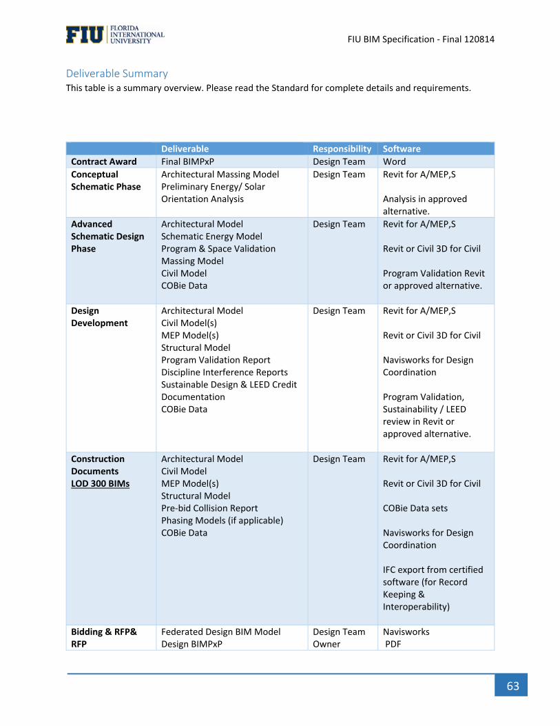
` FIU BIM Specification ‐ Final 120814
63
Deliverable Summary This table is a summary overview. Please read the Standard for complete details and requirements.
Deliverable Responsibility Software
Contract Award Final BIMPxP Design Team Word
Conceptual Schematic Phase
Architectural Massing Model Preliminary Energy/ Solar Orientation Analysis
Design Team Revit for A/MEP,S Analysis in approved alternative.
Advanced Schematic Design Phase
Architectural Model Schematic Energy Model Program & Space Validation Massing Model Civil Model COBie Data
Design Team Revit for A/MEP,S Revit or Civil 3D for Civil Program Validation Revit or approved alternative.
Design Development
Architectural Model Civil Model(s) MEP Model(s) Structural Model Program Validation Report Discipline Interference Reports Sustainable Design & LEED Credit Documentation COBie Data
Design Team Revit for A/MEP,S Revit or Civil 3D for Civil Navisworks for Design Coordination Program Validation, Sustainability / LEED review in Revit or approved alternative.
Construction Documents LOD 300 BIMs
Architectural Model Civil Model MEP Model(s) Structural Model Pre‐bid Collision Report Phasing Models (if applicable) COBie Data
Design Team Revit for A/MEP,S Revit or Civil 3D for Civil COBie Data sets Navisworks for Design Coordination IFC export from certified software (for Record Keeping & Interoperability)
Bidding & RFP& RFP
Federated Design BIM Model Design BIMPxP
Design Team Owner
Navisworks PDF
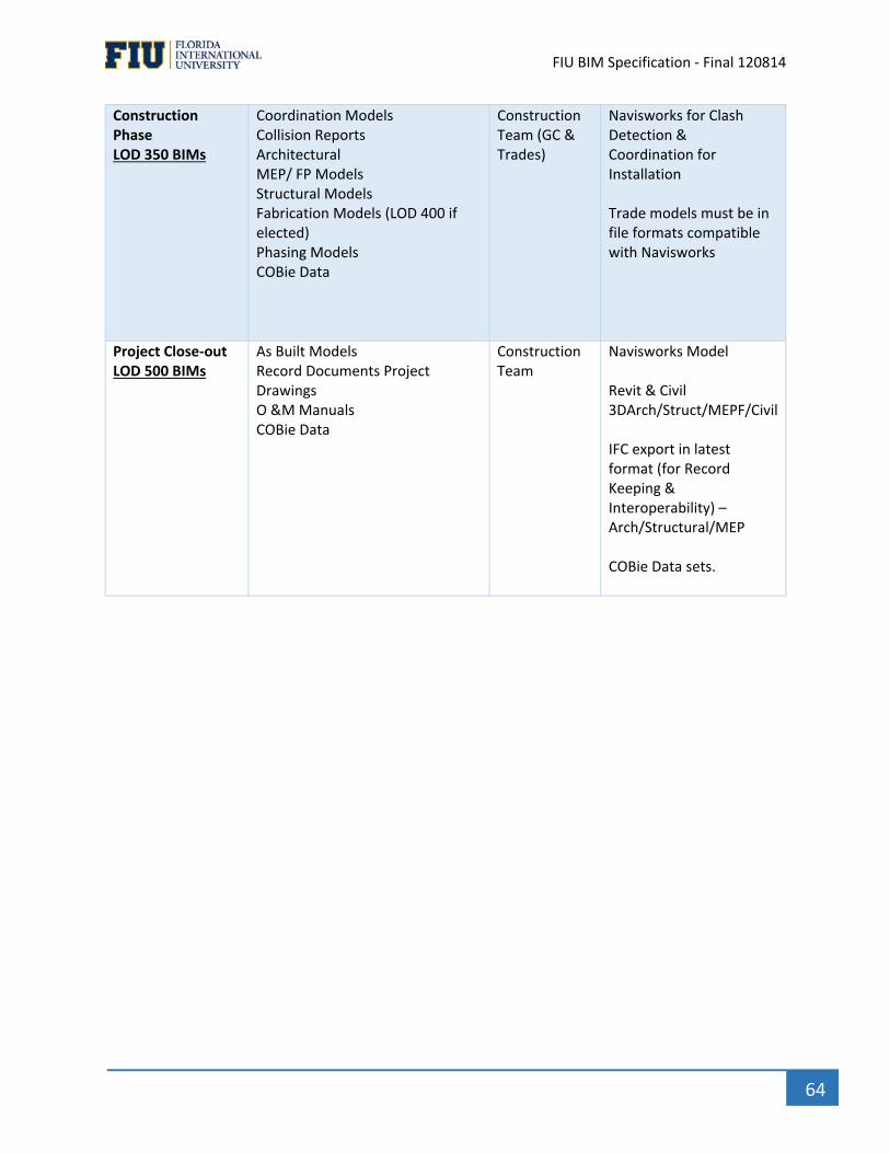
` FIU BIM Specification ‐ Final 120814
64
Construction Phase LOD 350 BIMs
Coordination Models Collision Reports Architectural MEP/ FP Models Structural Models Fabrication Models (LOD 400 if elected) Phasing Models COBie Data
Construction Team (GC & Trades)
Navisworks for Clash Detection & Coordination for Installation Trade models must be in file formats compatible with Navisworks
Project Close‐out LOD 500 BIMs
As Built Models Record Documents Project Drawings O &M Manuals COBie Data
Construction Team
Navisworks Model Revit & Civil 3DArch/Struct/MEPF/Civil IFC export in latest format (for Record Keeping & Interoperability) –Arch/Structural/MEP COBie Data sets.
` FIU BIM Specification ‐ Final 120814
65
Glossary
2D Two dimensional
3D Three dimensional
4D BIM + Schedule (Time) = 4D
5D BIM + Cost = 5D
A/E Architect and Engineer
AHJ Authorities Having Jurisdiction (AHJ)
As‐Constructed BIM The updated Contractor BIMs which represent what was installed in the field.
As‐Built BIM Design Intent Models that have been updated throughout the construction
process. These changes and updates have been communicated from the GC to
the Designer through comments, annotations and mark‐ups from the As‐Built
Documents or red lines.
BIM Building Information Model or Building Information Modeling
BIM Proficiency Matrix A matrix design to measure the expertise of the firm as it relates to using
BIM on a project.
BIMPxP Building Information Modeling Project Execution Plan
BPM BIM Project Manager
CAD Computer‐Aided Design
CAFM Computer‐ Aided Facility Management
CD Construction Documents
CMMS Computerized Maintenance Management System: A type of management
software that performs functions in support of operations and maintenance
(O&M) programs.
COBie Construction Operation Building Information Exchange. An information standard
that captures facility data generated during the facility’s design, construction
and commissioning phases. It is a data Specification.
CPS COBie Progression Schedule
Construction BIM Building Information Model typically representing a single building system
created for purposes of planning, scheduling, coordinating, fabricating, and
installing during construction. Model elements are accurate in terms of size,
shape, location, quantity and orientation and may include fabrication, assembly,
detailing and non‐geometric information. MEPF System models include COBie
` FIU BIM Specification ‐ Final 120814
66
data. Construction BIMs are maintained in the native format of the authoring
software.
Coordination BIM Composite model that includes multiple Design or Construction BIMs, registered
spatially, used for the purpose of interference checking (clash detection),
visualization and 4D applications during construction. Coordination BIMs are
maintained in the native format of the coordination software.
CI Contractor Installation
Csa Contractor Submittal Approval
D100 100% Design Stage / Construction Document
DB Design Build
DD Design Development
DQC Deliverable Quality Control
DWG DWG is a binary file format used for storing two and three dimensional design
data and metadata. It is the native format for several CAD packages.
Federated Model An aggregation of Models in a single database.
FLCM Facility Life Cycle Management
FM Facility Management or Facility Manager
IFC (2X3) Industry Foundation Classes: an object oriented neutral file format with a data
model developed by the buildingSMART (International Alliance of
Interoperability, IAI) to describe, exchange and share information typically used
with the building and facility management industry sector. IFC (2X3) is an
International Standard. (ISO 16739)
JBIMPxP Joint BIM Project Execution Plan
Level of Detail The amount of parts modeled inside an object or system.
LOD Level of Development. The specific minimum content requirements and
associated Authorized Uses or each Model Element at six progressively detailed
levels of completeness.
MasterFormat , a publication of CSI and CSC, is a master list of numbers and titles classified by
work results. It primarily used to organize project manuals and detailed cost
information, and to relate drawings notations to specifications.
MEPF Mechanical, Electrical, Plumbing, Fire Protection
MIR Model Information Request
` FIU BIM Specification ‐ Final 120814
67
MPS Model Progression Schedule (MPS) also known as the Model Element Table as
referenced in the AIA G202 document and is a matrix that defines specific
model elements by Uniformat classification.
NBIMS National Building Information Modeling Standard‐ United States, Version 2
(NBIMS‐US v2)
OmniClass OmniClass Construction Classification System – Open Source‐ is a classification system for the construction industry. It incorporates other extant systems currently in use as the basis of many of its Tables – MasterFormat for work results and UniFormat for elements.
PxP Project Execution Plan
Record BIM The updated BIMS that come from the architect that includes the contractors AS
Constructed BIMS.
RFI Request for Information
RFP Request for Proposal
RFQ Request for Qualifications
RP Responsible Party
SD Schematic Design
VDC Virtual Design and Construction
VDCO Virtual Design Construction and Operation (VDCO)
VMP Version Management Process

` FIU BIM Specification ‐ Final 120814
68
Acknowledgements Florida International University would like to thank all who contributed research, knowledge, effort and
time in the development of this BIM Standard.
Developed by: FIU BIM Committee: Chaired by Mr. Brian Perez
VDCO Tech, Inc
For Further Information about this Standard or to submit comments or questions, please contact:
Florida International University Mr. Brian Perez Florida International University
11555 SW 17th Street
Modesto Maidique Campus
Miami, FL 33199
References Used: National Building Information Modeling Standard – United States, Version 2 (NBIMS‐ US v2)
BIM Forum’s 2013 LOD Specification
Construction Specification Institute (CSI) 2011 OmniClass Tables
LACCD Building Information Modeling Standard
University of Florida BIM Guides & Standards
Indiana University BIM Guideline
VA BIM Guide 2012
Broward County Aviation Department (BCAD) ‐ BIM Standard
George Tech University
USC BIM Guidelines


![BUILDING INFORMATION MODELING [BIM]](https://img.pdfslide.us/doc/110x75/568c3a761a28ab0235a64bb9/building-information-modeling-bim-56f20f2323409.jpg)