Embed Size (px)
Citation preview

Building Extensible and Secure Networks
by
Lucian Popa
A dissertation submitted in partial satisfaction of the
requirements for the degree of
Doctor of Philosophy
in
Computer Science
in the
Graduate Division
of the
University of California, Berkeley
Committee in charge:
Professor Ion Stoica, ChairProfessor Sylvia Ratnasamy
Professor Daniel Tataru
Fall 2011

Building Extensible and Secure Networks
Copyright 2011by
Lucian Popa

1
Abstract
Building Extensible and Secure Networks
by
Lucian Popa
Doctor of Philosophy in Computer Science
University of California, Berkeley
Professor Ion Stoica, Chair
In this dissertation, we present a network design called Rule-Based Forwarding (RBF)that provides flexible and policy-compliant forwarding. Our proposal centers around a newarchitectural concept: that of packet rules. A rule is a simple if-then-else construct thatdescribes the manner in which the network should – or should not – forward packets. Apacket identifies the rule by which it is to be forwarded and routers forward each packet inaccordance with its associated rule. On one hand, rules are flexible, as they can explicitlyspecify paths and invoke packet processing inside the network. This enables RBF to supportmany previously proposed Internet extensions, such as explicit middleboxes, multiple paths,source routing and support for host mobility. On the other hand, rules are certified, whichguarantees that packets comply with the policies of the parties forwarding them. Thisproperty also enables a more secure architecture, since unwanted packets can be droppedin the network, allowing RBF to stop denial of service (DoS) attacks. Using our prototyperouter implementation we show that the overhead RBF imposes is within the capabilities ofmodern network equipment.
We also describe how the ideas behind RBF can be used to improve access control incloud computing, and present CloudPolice an access control mechanism implemented inhypervisors. CloudPolice scales to millions of hosts, is independent of the network topology,routing and addressing, and can specify flexible access control policies. These propertiesare not provided by traditional access control mechanisms, because these mechanisms wereoriginally designed for enterprise environments that do not share the same challenges ascloud computing.

i
To my wife and my parents

ii
Contents
1 Introduction 11.1 Contributions . . . . . . . . . . . . . . . . . . . . . . . . . . . . . . . . . . . 41.2 Organization . . . . . . . . . . . . . . . . . . . . . . . . . . . . . . . . . . . 5
2 Design Rationale and Overview 62.1 Architecture Overview . . . . . . . . . . . . . . . . . . . . . . . . . . . . . . 7
2.1.1 Distributing rules to routers . . . . . . . . . . . . . . . . . . . . . . . 72.1.2 Applying Rules . . . . . . . . . . . . . . . . . . . . . . . . . . . . . . 82.1.3 Distributing rules to end-hosts . . . . . . . . . . . . . . . . . . . . . . 92.1.4 Ensuring Rules Are Authorized . . . . . . . . . . . . . . . . . . . . . 92.1.5 Assumptions . . . . . . . . . . . . . . . . . . . . . . . . . . . . . . . . 102.1.6 Summary . . . . . . . . . . . . . . . . . . . . . . . . . . . . . . . . . 10
3 RBF Data Plane 123.1 Rule Specification . . . . . . . . . . . . . . . . . . . . . . . . . . . . . . . . . 123.2 Rule Verification . . . . . . . . . . . . . . . . . . . . . . . . . . . . . . . . . 153.3 Usage Examples . . . . . . . . . . . . . . . . . . . . . . . . . . . . . . . . . . 163.4 Source Rules . . . . . . . . . . . . . . . . . . . . . . . . . . . . . . . . . . . . 253.5 Functions on Both Forward and Reverse Paths . . . . . . . . . . . . . . . . . 26
4 RBF Control Plane 284.1 Rule Creation and Certification . . . . . . . . . . . . . . . . . . . . . . . . . 284.2 Rule Distribution . . . . . . . . . . . . . . . . . . . . . . . . . . . . . . . . . 33
4.2.1 Distributing Rules for DDoS Protection . . . . . . . . . . . . . . . . . 344.3 Rule Leases . . . . . . . . . . . . . . . . . . . . . . . . . . . . . . . . . . . . 34
4.3.1 Alternative Lease Mechanism Not Using Global Synchronization . . . 354.4 Anti-spoofing mechanism . . . . . . . . . . . . . . . . . . . . . . . . . . . . . 36
5 Security Analysis 375.1 Security Properties . . . . . . . . . . . . . . . . . . . . . . . . . . . . . . . . 375.2 Mechanisms . . . . . . . . . . . . . . . . . . . . . . . . . . . . . . . . . . . . 38

iii
5.3 Analysis . . . . . . . . . . . . . . . . . . . . . . . . . . . . . . . . . . . . . . 38
6 Evaluation 436.1 Implementation . . . . . . . . . . . . . . . . . . . . . . . . . . . . . . . . . . 43
6.1.1 An RBF Rule Compiler . . . . . . . . . . . . . . . . . . . . . . . . . 436.1.2 A Prototype RBF Router . . . . . . . . . . . . . . . . . . . . . . . . 44
6.2 Evaluation Results . . . . . . . . . . . . . . . . . . . . . . . . . . . . . . . . 456.2.1 Packet Size Overhead . . . . . . . . . . . . . . . . . . . . . . . . . . . 456.2.2 Router Overhead . . . . . . . . . . . . . . . . . . . . . . . . . . . . . 476.2.3 Router Functions . . . . . . . . . . . . . . . . . . . . . . . . . . . . . 516.2.4 RCE Load . . . . . . . . . . . . . . . . . . . . . . . . . . . . . . . . . 53
7 Related Work 54
8 Discussion and Limitations 588.1 Discussion on Policy Compliance . . . . . . . . . . . . . . . . . . . . . . . . 598.2 Incremental Deployment Through Infrastructure Upgrade . . . . . . . . . . . 608.3 Limitations of RBF . . . . . . . . . . . . . . . . . . . . . . . . . . . . . . . . 61
8.3.1 Using Mobility and DoS Protection Simultaneously . . . . . . . . . . 618.3.2 Rule Expressivity . . . . . . . . . . . . . . . . . . . . . . . . . . . . . 628.3.3 ICMP-like protocols . . . . . . . . . . . . . . . . . . . . . . . . . . . 63
9 CloudPolice - Applying RBF to Data Centers and Cloud Computing 649.1 Background . . . . . . . . . . . . . . . . . . . . . . . . . . . . . . . . . . . . 65
9.1.1 Examples of Cloud Access Control Policies . . . . . . . . . . . . . . . 669.1.2 Properties Required for Cloud Access Control . . . . . . . . . . . . . 69
9.2 CloudPolice Overview . . . . . . . . . . . . . . . . . . . . . . . . . . . . . . 699.2.1 Design Space . . . . . . . . . . . . . . . . . . . . . . . . . . . . . . . 709.2.2 CloudPolice’s Design . . . . . . . . . . . . . . . . . . . . . . . . . . . 70
9.3 Detailed Design and Implementation . . . . . . . . . . . . . . . . . . . . . . 719.3.1 Proposed Policy Model . . . . . . . . . . . . . . . . . . . . . . . . . . 719.3.2 Design Details . . . . . . . . . . . . . . . . . . . . . . . . . . . . . . . 749.3.3 Implementation and Evaluation of Overhead . . . . . . . . . . . . . . 769.3.4 Security Analysis . . . . . . . . . . . . . . . . . . . . . . . . . . . . . 79
9.4 Related Work . . . . . . . . . . . . . . . . . . . . . . . . . . . . . . . . . . . 83
10 Future Work 8410.1 Extending RBF . . . . . . . . . . . . . . . . . . . . . . . . . . . . . . . . . . 8410.2 Deploying RBF Through HTTP . . . . . . . . . . . . . . . . . . . . . . . . . 8510.3 Extending CloudPolice . . . . . . . . . . . . . . . . . . . . . . . . . . . . . . 86
11 Conclusion 87

iv
Bibliography 88
A Static Analysis of Rules for Forwarding Loops 94A.1 Rule FSM . . . . . . . . . . . . . . . . . . . . . . . . . . . . . . . . . . . . . 95A.2 The Loop-Free Rule (LFR) algorithm . . . . . . . . . . . . . . . . . . . . . . 96A.3 Proving Rule Safety . . . . . . . . . . . . . . . . . . . . . . . . . . . . . . . . 100A.4 Complexity . . . . . . . . . . . . . . . . . . . . . . . . . . . . . . . . . . . . 101
B Static Analysis of Rules for Local Loops 102

v
Acknowledgments
I am extremely grateful to my advisor, Ion Stoica for guiding me through my graduatestudies. Ion has been an amazing advisor and is a wonderful person. I have learned a greatdeal from Ion, especially on how to approach a research problem by decoupling propertiesfrom the mechanism and trying to come up with simple solutions. I am still working on that!I thank Ion for always encouraging me through a positive attitude and for finding time tomeet with me even during his busiest periods.
I also want to thank Sylvia Ratnasamy for her immense contribution to the work inthis dissertation. I am also very grateful to Sylvia for the opportunity to have an extendedinternship, during which I had a productive learning experience. Sylvia taught me a lot abouthow to structure and present research ideas. Future students will be extremely fortunate tohave her as an advisor.
I am also grateful to my undergrad advisor, Irina Athanasiu, whom I deeply miss, andwithout whom I would not be here. Rest in peace Irina.
The research comprised into my thesis is joined work with Norbert Egi, Vjekoslav Bra-jkovic, Minlan Yu, Steven Y. Ko, Arvind Krishnamurthy, Sylvia Ratnasamy and Ion Stoica,and I am grateful to them. I thank the other members of my qualifying exam committeeScott Shenker and Daniel Tataru for their feedback on my work.
I was fortunate to have a number of collaborators and friends that I profoundly thank,among which: Costin Raiciu, Sergiu Nedevschi, David Chu, Ali Ghodsi, Ovidiu Savin,Ioan Berbec, Gianluca Iannaccone, Byung-Gon Chun, Jaideep Chandrashekar, Dilip Joseph,Brighten Godfrey, Arsalan Tavakoli, Gautam Altekar, Matei Zaharia, Rodrigo Fonseca, NinaTaft, Afshin Rostamizadeh and Vyas Sekar. I am also grateful to several Berkeley professors,including: Christos Papadimitriou, Richard Karp and Joseph Hellerstein. Special thanks toRadu Teodorescu for giving me the opportunity to work on a research project as an under-grad; I would not be here without that opportunity. I am also grateful to Mihai Budiu forthe great experience I had during my internship.
I want to thank my mother Veronica, my father Valentin and my brother Ovidiu forencouraging me to pursue graduate studies, for their support and for their love. They arethe most amazing family in the world.
Last but not least, I am deeply indebted to my dear wife Iuliana for her incredible supportduring my PhD. Iuliana has been the most understanding wife on earth, always supportingme during the busy periods, despite the fact that, as a consequence, we spent less timetogether. She always encouraged me and gave me the strength to continue. Thank youIuliana for your love and your sacrifices.

1
Chapter 1
Introduction
A central component of a network design is its forwarding architecture that determinesthe manner in which packets are transported between two endpoints. Today’s Internetoffers users a simple forwarding model: a user hands the network a packet with a destinationaddress and the network makes a best-effort attempt to deliver the packet to the destination.Although simple, this architecture is also fairly limited and there have been repeated calls toextend the Internet’s forwarding architecture for greater flexibility—allowing, for example,the user to select the path his packets should traverse [36, 90, 98, 104] or to specify whetherpackets can/should be processed by middleboxes and active routers [42,61,98,101,104].
Achieving a flexible forwarding architecture has thus been a long-held, if elusive, goalof Internet research [36, 42, 61, 86, 98, 101, 104]. Our work in this dissertation shares thisgoal. Our point of divergence from prior efforts starts with the observation that forwardingflexibility is inherently coupled with issues of policy.
Our thesis is that achieving flexibility is not just a matter of augmenting packets withmore expressive forwarding directives that routers execute. Rather, in addition, for eachforwarding directive that enhances flexibility, the parties involved in forwarding should beable to set policies that constrain that directive. By the policy of entity A (host, middleboxoperator or ISP) we refer to the decision whether to approve or reject a forwarding directivebased on A’s business or technical goals. By forwarding directive we refer to instructionsprovided by endpoints to routers and middleboxes on how to forward their packets. Forexample, a forwarding directive could specify that sender S can forward its packets throughmiddlebox M before reaching destination D. An example of policy would be M refusing toaccept packets from S.
To better illustrate our thesis, consider its application to the Internet. Since the mainforwarding directive in IP is for sender S to send packets to destination D, D should be ableto specify that the traffic from S should not reach it, i.e., either by explicitly allowing ordenying packets from D. Unfortunately, IP does not provide such functionality, effectivelyleaving the end-hosts vulnerable to DoS attacks. Unsurprisingly, this lack of functionalityhas been identified as one of the main security vulnerabilities of the Internet, and several

2
solutions have been proposed to address this limitation [37,38,68,78,108,110].Of course, forwarding directives and policies are only as good as the ability of the network
to enforce them and to guarantee their authenticity. What complicates policy enforcement isthe involvement of multiple parties in achieving the packet’s flexible behavior—the networkservice providers along the path, potential middlebox operators and, of course, the sourceand destination. As such, the network must ensure that a packet’s forwarding directivecomplies with the policies of all parties involved. In our previous middlebox example, thenetwork must ensure that M is willing to relay packets from S to D. If M does not approve,the network should simply drop the packets before reaching M.
In this dissertation, we propose a new rule-based forwarding architecture, RBF, thattreats flexibility and policy enforcement as equal design goals. RBF is based on a new archi-tectural concept – that of packet rules. In RBF, instead of sending packets to a destination(IP) address, end-hosts send packets to a rule. Rules are created by destinations. A senderfetches the destination’s rule from a DNS-like infrastructure and inserts it in the packetssent to that destination.
A rule is a simple if-then-else construct that describes the manner in which the net-work should – or should not – forward packets. For example, a destination A can receivepackets only from source S using the rule:
RA : i f ( packet . source 6= S)drop packet
Or a mobile client B might route certain video content through a 3rd-party transcoding proxywith:
RB : i f ( packet .URL = videowebs i t e . com)sendPacketTo transcoderProxy
The above examples are anecdotal (we present precise syntax Section 3 and additionalexamples in Section 3.3) but serve to illustrate how destinations can control and customizehow the network forwards their packets in a manner not easily accommodated by current IP.In effect, with rules, a receiving host must specify both which packets it is willing to receiveas well as how it wants these packets forwarded and processed by the network.
The rule-based architecture we develop offers the following properties:
1. Rules are mandatory: routers drop packets without rules
2. Rules are provably authorized: all recipients (end-hosts, middleboxes and/orrouters) named in the rule must explicitly agree to receive the associated packet(s).Routers, middleboxes and end-users can verify a rule’s authorization.
3. Rules are provably safe: rules cannot exhaust network resources (e.g., cause for-warding loops) and cannot compromise routers.

3
4. Rules allow flexible forwarding: rules are a (constrained) program that allows auser to “customize” how the network forwards its packets.
The first two properties assist in policy enforcement by ensuring a packet is only forwardedif explicitly cleared by all recipients (i.e., if it conforms with the policies of all recipients)specified in the rule. Since RBF defines policies on rules, any recipient will have the ultimatesay on whether to accept any rule that contains forwarding directives sending packets to it.Since all forwarding directives are encoded into rules, we achieve our goal of enabling anyentity affected by a forwarding directive to constrain that directive.
The third property ensures rules cannot be (mis)used to attack the network itself. As weshall show, the last property provides flexibility since users can give the network fine-grainedinstructions on how to handle their packets, enabling: explicit use of in-network functionalityat middleboxes and routers, loose path forwarding, multipath forwarding, anycast, multicast,mobility, filtering of undesired senders/ports/protocols, recording of on-path information,etc. In this dissertation, we present the design, implementation and evaluation of a forwardingarchitecture that meets the above properties.
RBF relates to an extensive body of work on both forwarding flexibility and policyenforcement. We discuss related work in detail in Section 7 and here only note that, ata high level, we believe what distinguishes RBF is its focus on simultaneously supportingflexibility and the multi-party policy requirements that such flexibility implies. As we shallsee, this goal leads us to a design that differs significantly from prior proposals.
We note up-front that RBF is more complex than the existing IP forwarding architecture,which is frequently cited for its simplicity. In addition, RBF relies on strong assumptions suchas anti-spoofing, the existence of rule-certifying authorities and a DNS-like infrastructureto distribute rules. The gain, relative to today’s IP forwarding, is significantly improvedflexibility and security; we posit that the greater complexity of our solution is a perhapsinevitable consequence of this richer service model.
In this dissertation, we also explore the application of the core ideas behind RBF tocloud computing. Cloud computing is growing in importance as a new paradigm for accessto computational resources. Core to cloud computing is the ability to share and multiplexresources across multiple users. Since cloud computing environments are shared by multipleusers, they should ideally provide network-level access control mechanisms between users(typically called tenants). The majority of existing access control techniques used for cloudcomputing were originally designed for enterprise environments. However, compared to en-terprises, cloud computing environments impose new challenges on access control techniquesdue to multi-tenancy, the growing scale and dynamicity of hosts within the cloud infrastruc-ture, and the increasing diversity of data center network architectures. Therefore, the accesscontrol mechanisms inherited from enterprises are poorly suited for cloud environments. Infact, as cloud computing services evolve, they run into analogous security and inflexibilityproblems as the Internet. Clouds are expanding to very large sizes (currently, hundreds ofthousands of machines) and, like the Internet, they have tens of thousands of users. The

4
latter also leads to growing concerns about potential DoS attacks between users inside thecloud. One of the properties offered by RBF is access control at the Internet level.
Starting from this observation, we propose CloudPolice. Similarly to RBF, in CloudPolicethe access control decisions are specified by each destination on the control plane (conformingto the destination’s policy) and are enforced on the data plane by having packets carry aproof of their policy compliance. On the other hand, CloudPolice takes advantage of thefact that, unlike the Internet, each cloud is owned by a single administrative domain thatowns not only the network, but also the servers. In particular, cloud computing is typicallya virtualized environment, where a trusted layer of software, the hypervisor, sits betweeneach customer machine and the network. In this context, we argue that it is both sufficientand advantageous to implement access control only within hypervisors at end-hosts. For thisreason, CloudPolice has a lower overhead and is easier to adopt when compared to RBF. Infact, cloud providers can adopt CloudPolice through a simple software update to hypervisors,without requiring any hardware upgrades or changes to applications. Our evaluation showsthat CloudPolice does not impose a significant overhead on hosts.
1.1 Contributions
The contributions of this dissertation are as follows:
1. We present the design of RBF, a first network architecture that is both flexible andpolicy compliant. While many have proposed more flexible networks, we argue thatadding more flexibility alone can, in fact, lead to less secure architectures. In addition,we argue that respecting the policy of destinations is also necessary in order to improvethe security of today’s networks and block DoS attacks. Furthermore, the lack of aguaranteed policy compliance property is one of the reasons that makes the adoptionof new architectural proposals difficult, since, without such a property, many of theISPs’ concerns are not addressed.
2. We analyze RBF’s flexibility and its security properties. We show that RBF cansupport a large number of desirable and previously proposed extensions to today’snetworks such as explicit use of in-network functionality at middleboxes and routers,loose path forwarding, multipath forwarding, anycast, multicast, mobility, filtering ofundesired senders/ports/protocols, recording of on-path information, etc. Our securityanalysis shows that RBF is resistant to attacks from endpoints trying to forge, tamperor evade rules and that users cannot create malicious rules to attack the network itself.
3. We evaluate RBF’s feasibility. We show that the increase in the traffic size for through-put intensive applications can be as low as 6% on average. Using a prototype softwarerouter implementation, we show that RBF’s overhead compared to the state of the artsoftware routers is minimal.

5
4. We present CloudPolice, a mechanism to implement access control in cloud computinginspired by RBF. Compared to the traditional access control mechanisms inheritedfrom enterprises, CloudPolice can scale to millions of hosts, is independent of thenetwork topology, routing and addressing, and can specify more flexible access controlpolicies. In addition, CloudPolice is easy to adopt by cloud providers, requiring onlya software update.
1.2 Organization
This dissertation is organized as follows. We start by presenting the design rationale andthe overview of RBF in Section 2. We then present the details of RBF’s data plane and aset of examples that can be supported by using the described data plane (Section 3). Next,we detail RBF’s control plane (Section 4). Section 5 presents a security analysis of RBF andSection 6 presents details of the implementation and evaluation of RBF. We present relatedwork in Section 7 and discuss different concerns associated with RBF and RBF’s limitationsin Section 8. Section 9 presents CloudPolice, a mechanism inspired by RBF to provide accesscontrol in data centers. Finally, Section 10 outlines our plans for future work and Section 11concludes this dissertation.

6
Chapter 2
Design Rationale and Overview
We start with the goal of network flexibility and allowing users control over how the net-work processes their packets. The abstraction that perhaps best supports flexibility is simplythat of a program, leading to an architecture where users write packet-processing programsthat routers execute. This vision of code-carrying packets is, of course, the cornerstoneof active networking [101, 105] and we borrow this as our starting point in designing RBF.However, as we shall see, RBF severely dials back on the full-fledged generality of the originalactive networks’ vision to arrive at a significantly simpler and safer architecture.
Rules are thus a form of program. The challenge then is to appropriately constrain theseprograms/rules to ensure that they cannot harm the network or other hosts. The key insightbehind RBF is that these constraints must extend along two dimensions. First, rules must besafe, i.e., guaranteed not to corrupt or exhaust network resources. In addition, however, wemust constrain rules to respect the policies of all stakeholders involved—source, destination,middleboxes and ISPs. This latter requirement is unique and yet critical to networkingcontexts but was under appreciated in early active networking proposals.
To address policy safety, RBF incorporates two key design decisions:
• (D1) Layering: we believe network operators will be unwilling to relinquish control ofroute discovery and computation and hence we layer RBF above current IP forwardingand do not allow rules to modify the IP-layer forwarding information base (FIB).
• (D2) Verifiable stakeholder agreement: we require that a rule be authorized byall entities it explicitly names (e.g., destination, middleboxes or routers). This ensuresagreement of the stakeholders’ policies with the rule’s intent; in particular it alsoensures that rules cannot violate ISPs’ routing policies, since providers must explicitlyagree to have their routers named in rules. To achieve this property, in RBF rulesare certified by trusted third parties, which in turn gather proofs of policy compliancefrom each of the rule participants.
To address rule safety, we impose strict constraints on rule syntax, such that safety canbe verified through simple static analysis:

7
• (C1) Rules cannot directly modify router state. This avoids corruption of routerstate. However, this can be a limiting restriction, particularly to network operatorswho wish to expose in-network services such as caching or monitoring to end users.To accommodate this, RBF allows operators to deploy specialized packet-processingfunctions at their routers and allows rules to invoke these functions. Such “router-defined functions” do allow rules to update router state, but only indirectly via codeinstalled, and hence presumably trusted, by operators. This model for router-definedfunctions thus represents a middle ground in the tradeoff between flexibility and safety.
• (C2) The rule “instruction set” is limited to only four possible action statements:(a) forward the packet to the underlying IP layer, (b) invoke a router-defined function,(c) modify the packet header and (d) drop the packet, plus conditionals that determinewhether an action should be taken based on reading packet headers and router state.Note that there is no action that allows backward jumps across rule statements. Thisprevents looping or resource exhaustion at routers and ensures execution time is linearin program size.
The above constraints represent a stark departure from the rich generality of the activenetworks vision. Indeed, rules are more a sequence of packet steering directives, rather thana full-fledged program. The benefit is verifiable rule and policy safety. Moreover we findthat, despite these constraints, rules suffice to express a wide variety of forwarding behaviorsas we will later illustrate.
2.1 Architecture Overview
In this section we provide an overview of the main components and assumptions of theRBF architecture and the rationale behind their design. The subsequent sections of thisdissertation will present the detailed design of these components.
With RBF, end-users control packet forwarding using rules. Each packet has an associ-ated rule and contains a set of attribute-value pairs in its header. Upon receiving a packet,the router forwards the packet conforming to the packet’s rule.
2.1.1 Distributing rules to routers
To process a packet, a router needs to know the rule associated with the packet. There aretwo basic approaches by which routers can obtain rules: (1) rules are carried in packets, (2)routers use an out-of-band mechanism to obtain the rules.
Carrying rules in packets frees routers from maintaining per-rule state, and implementingcostly rule distribution protocols. On the other hand, this approach incurs a high overheadon the data plane as rules increase packet headers, and routers need to verify the rules toensure their validity.

8
IDS
ulticast
aching Specialized
forwardingfunctions
…
Mu Ca functions
(optional)
RuleForwarding
Router Attributes
RBF
FIB IPIPForwarding
R l A ib 1 R l A ib 2Rule Attributes 1 Rule Attributes 2
Figure 2.1: RBF router and rule forwarding
In contrast, installing rules at routers has a lower overhead on the data plane, as packetsneed only to carry rule identifiers instead of the rules themselves. However, the process ofobtaining rules can be complex; the router can either get rules in advance, in which case itmay need to store a huge number of rules or the router can download rules on demand, inwhich case the router may need to buffer the packets it receives until it obtains the rulesfor those packets. Moreover, since we do not want to have any type of “special” traffic thattravels without using rules, the packets installing rules have to themselves travel on rules.This makes the rule installation process very difficult.
For these reasons, we chose to have packets carry rules. In Section 6 we evaluate theoverhead of rules.
2.1.2 Applying Rules
Figure 2.1 illustrates the forwarding architecture of an RBF-enabled router. On receiving apacket, the router hands it to the rule forwarding engine, which processes the packet’s rule.Such processing may involve reading router state that the network operator has opted toexpose; we term such state router attributes. Examples of routing attributes may include therouter’s IP address, AS number, congestion level, flags indicating whether the router imple-ments a specific functionality such as intrusion detection and so forth. Based on informationin the packet header (packet attributes) and router attributes, the rule forwarding engine mayupdate the value of the packet attributes (including its destination), invoke router functions,drop the packet and/or hand the packet to the underlying IP forwarding engine. Recall thatfor safety reasons the rule is not allowed to update router state.

9
2.1.3 Distributing rules to end-hosts
As discussed above, in our instantiation of RBF, rules are carried in the packets. Since thefirst router on the packet’s path expects each packet to carry its associated rule, rules needto be inserted by senders. Furthermore, since in general rules are provided by destinations,there needs to be a way for senders to obtain these rules.
RBF leverages an extended DNS infrastructure to distribute rules. The end-hosts (orother entities on their behalf) publish rules to the infrastructure. In turn, each senderqueries this infrastructure to obtain the destination’s rule, similarly to the way the senderqueries DNS to obtain the receiver IP address. This is the common case of distributing rules.
2.1.4 Ensuring Rules Are Authorized
To guarantee that entities participating in a rule authorize the rule, each rule is certified bya third party certifying authority, called Rule Certification Entity, or RCE for short. TheRCE guarantees that all nodes whose addresses appear explicitly in a rule (i.e., destinations,middleboxes and indirection routers) agree with the rule. In addition, the RCE may verifythe rule for forwarding-loops before certifying it (see Section 5 and Appendices A and B).Upon receiving a packet, an RBF router verifies the rule’s signature. If the verification fails,the router drops the packet; otherwise, the router applies the rule.
Since a rule cannot use a router as an indirection point without the router agreement,the ISP that owns the respective router retains full control on packet forwarding at the IPlayer.
Thus, the RBF architecture consists of four main components:
• The specification of packet rules – their syntax, packet encoding, constraints on whatrules can and cannot do. We discuss the details for the rule specification in Section 3.
• Certificate authorities called Rule Certification Entities (RCEs) that certify rules afterchecking that they are well formed, and that every destination specified in the ruleagrees with (i.e., has signed) the rule. We discuss the details of rule certification inSection 4.
• Modified IP routers that verify rule certificates and process packets as described above.We present a prototype router implementation and evaluation in Section 6.
• A modified DNS infrastructure that either directly resolves a host D’s domain name toD’s rule, or resolves D’s domain name to another rule resolution server which in turnprovides D’s rule. We discuss the details of rule distribution in Section 4.

10
2.1.5 Assumptions
RBF builds on three major assumptions.
Anti-Spoofing: First, RBF assumes the existence of an anti-spoofing mechanism. This isrequired because rules may use source and destination IP addresses in their decision processand hence addresses must be legitimate, otherwise policy compliance cannot be enforced.Note that any solution for blocking undesired traffic inside the network requires a way toidentify sources. Anti-spoofing identifies users based on their addresses. An alternative, isto identify users by their access path [108,110], however this approach ties communicationsto a specific path restricting flexibility (e.g., for mobility, traffic engineering, multi-pathforwarding). In this dissertation we assume the use of ingress filtering as the anti-spoofingmechanism, although RBF can accommodate alternate solutions, e.g., Passports [77]. Therationale behind our choice of ingress filtering is described in Section 4.
RCE Key Distribution: Second, we assume routers know the public keys of RCEs andcan thus verify rule certificates. We assume the number of RCE organizations is relativelysmall and these keys can be statically configured at routers, akin to how browsers todayare configured with the list of major certificate authorities. We discuss alternatives to thisdeployment in §4. Note that although we assume a small number of RCE organizations, weenvisage each organization will run geographically replicated instances of their service forimproved scalability and robustness.
Provisioning of Rule Distribution Infrastructure: Finally, we assume that the ruleresolution infrastructure (whether DNS or the resolution servers the DNS points to) is wellprovisioned, akin to how major Internet services (Google, DNS, Amazon) operate today,relying on engineering approaches such as maintaining a presence at major ISPs, IP any-casting, bandwidth provisioning, and so forth. As described in §4, we make this assumptionto protect against “denial of rule” attacks.
2.1.6 Summary
RBF can be succinctly described as:
1. Every packet contains a rule; there are no exceptions and no special traffic.
2. A rule is a set of forwarding directives associated to the packet by end-users; theexpressivity of rules enables forwarding flexibility.
3. Each rule bears a trusted entity’s signature, which guarantees the rule is authorizedand safe.
4. Routers verify the rule signature and forward conforming to the rule’s directives.

11
The described architecture supports RBF’s target properties as follows:
• Rules are mandatory: This is easily enforced; if a router receives a packet withouta rule, it simply drops the packet.
• Rules are provably authorized: Each rule is certified by an RCE, which guaranteesthat every destination or provider of router-defined function in the rule has authorized(signed) the rule. Any router and end-host can verify a rule certificate thus preventingattackers from modifying rules.
• Rules are provably safe: This follows from the constraints on rule syntax describedearlier. We constrain rules in three important ways that enable safety: (i) an RCEcertifies a rule only after checking that it cannot cause loops, (ii) a rule cannot directlymodify router state and hence cannot corrupt a router, (iii) rule execution time islinear in the size of the rule. We analyze attacks using rules and defenses in §5.
• Rules allow flexible forwarding: We illustrate this through examples in Section 3.3.
RBF assumes routers will incorporate support for rules (i.e., implement a rule forwardinglayer, specialized functionality, etc.) and allows users to specify rules thereby achievingflexibility. Importantly however, RBF’s design ensures that rules accommodate operatorpolicies and concerns – for example, the path specified in a rule cannot violate ISP routingpolicies, providers must explicitly agree to have their routers named in rules, rules can onlyoperate on explicitly exposed router attributes, any modification of router state or specializedpacket processing can only be achieved through provider-installed functions, and so forth.
In effect, with RBF, users and network operators share control over how routers processpackets. This feature distinguishes RBF from prior network architectures. Current IP allowsusers little control over how routers process their packets thereby limiting flexibility. At theother extreme: the active networks vision of routers executing code carried in packets allowedusers almost unlimited control, leading to grave security concerns. In a different approach,overlay-based architectures allow users flexibility without raising new security challengesbut cannot leverage in-network information and support and are thus less powerful. Forexample, overlay-based architectures can only drop unwanted packets at overlay nodes andhence cannot create a network that is fundamentally default-off, once the network-layeraddress of a node is known, it can always be attacked at the underlying network layer.
To conclude this overview, the RBF architecture consists of a data plane componentthat includes the rule forwarding mechanism and a control plane component that includesrule creation, certification and distribution; we describe each in detail in Sections 3 and 4respectively.

12
Chapter 3
RBF Data Plane
In this section we describe the key components of the RBF data plane – how users specifypacket rules and how routers verify and execute these rules.
3.1 Rule Specification
A rule can be represented by a simple transition table: based on the current value of packetattributes and router attributes, the rule may generate a new set of packet attributes andforward/drop the packet. In practice, we encode rules using an if-then-else tree-like structure,which has a more compact representation than a simple transition table.
Thus, a rule is represented by a sequence of actions that can be conditioned throughif-then-else structures of the following form:
i f (<CONDITION>)ACTION1
e l s eACTION2
Conditions are comparison operators applied on the packet and router attributes.The actions can be:
1. Forward the packet to the underlying IP forwarding engine;
2. Invoke a local function available at the router;
3. Drop the packet.
4. Update the value of the packet attributes;
Routers and hosts forward packets according to the actions specified by the rule. Whenone of the first three actions listed above (forward, invoke, drop) is encountered, the

13
R1Destination Rule
Packet Format:
AttributesRBFTransport Header
AD
R_D State = 0IP Header
R A’s attributes
R_D State = 1
R A R_A s attributesR_A
Figure 3.1: Simple indirection example.
application of the rule is ended and the appropriate action is executed. When the update
action is encountered, the value of the packet attribute is changed accordingly, and the ruleexecution continues.
The packet attribute set consists of the five-tuple in the IP header (i.e., IP addresses,ports, protocol type), and a number of custom attributes with user-defined semantics. Theuser-defined attributes can be used to identify different states that the packet finds itselfduring its journey through the network or to record information from the path. For simplicity,performance and security reasons, RBF does not allow rules to add new packet attributes.By default, user-defined packet attributes are initialized with the value zero, but can be setto a different value by senders.
Router attribute, on the other hand, can include the router’s IP address, AS number,congestion level, flags indicating whether the router implements a specific functionality suchas intrusion detection and so forth.
Packet attributes can be seen as having a local scope, since their semantics are associatedonly with the packet’s rule. Router attributes, on the other hand, have a global scope, sincethey have semantics shared by the rules of all the packets.
Each rule has an associated lease that ensures the rule can only be used for a limitedperiod of time. Routers drop packets with expired leases. For details on the lease mechanismsee Section 4.3.
Also, every rule has an identifier (ID) defined as the concatenation of a hash of the ruleowner’s public key and an index unique to the owner, hash(PK owner):index. In Section 6we present an optimization to reduce packet overhead and identify most rules by using ahash over their content. This optimization can be used in the common case when there isno need for multiple rules with the same identifier; for example, mobile hosts may requiredifferent rules with the same identifier (see §3.3).
For example, the following rule forwards a packet to a destination D via a waypoint routerR1; a packet attribute named state indicates whether or not the packet has already visitedR1:
R D :i f ( packet . s t a t e == 0) // from source to R1

14
i f ( r out e r . address != R1)sendto R1
e l s e packet . s t a t e = 1 // at R1 sending to Di f ( packet . s t a t e == 1)
sendto D
where the sendto action is a short form for the following: change the destination address toD and forward the packet using IP if D is not the local address, or forward it to the transportlayer otherwise. Once the packet is forwarded or dropped, the rule execution stops; the packetis by default dropped if it is not explicitly forwarded by the rule. Figure 3.1 illustrates thisexample, when D is communicating with another host A, who’s rule is R A.
While RBF does not allow rules to modify the packet payload or replicate packets, RBFenables rules to invoke such functionality at middleboxes or routers, if available. Thisallows RBF to leverage recent advancements in router design that enable network operatorsto provide new functionality through router extensions [27,28,81]. While the router functioninvoked by a rule at a router may modify the packet payload, may replicate packets andmay change the router state, such actions are done by code that is trusted and controlledby the network operator. The invoked router function will typically return the packet backto the forwarding layer with the same header (IP, RBF and transport), but potentially withmodified payload, and multiple replicas.
The generic structure or rules enables RBF to provide a rich set of forwarding functionali-ties, including explicit middlebox traversal, multi-path routing, anycast, multicast, and loosesource routing. We illustrate the generality of rules through a set of examples in Section 3.3.
Return rule: A packet with source S and destination D must include a destination rule,R D, which is the rule specified and owned by D. In addition, each packet may include areturn rule; this is the rule specified and owned by S and is used for return traffic from Dto S.
Expressivity: At a high-level, our rule specification can be viewed as defining a finite statemachine (FSM): the state is encoded in the packet attributes, while the input is representedby the attributes of the routers along the data path. The rule specifies the transition functionof the FSM. The RBF mechanism can theoretically implement any deterministic forwardingfunction that can change the packet attributes only. However, due to the limited size ofpackets, there are forwarding functions that cannot be efficiently expressed in RBF. Thislimitation is similar to the impracticality of implementing complex functions with the simpleFSM mechanism due to the exponential growth in the number of states. In particular,forwarding decisions based on any functions other than comparisons of packet and routerattributes (e.g., sum, hash, logarithm) are not practically expressible in RBF. For example,forwarding based on the sum of the addresses of routers on the path could not be easilywritten with rules. See Section 8.3 for a discussion on RBF’s limitations.

15
3.2 Rule Verification
As mentioned earlier, rules are certified by a Rule Certification Entity (RCE) and all packetscarry a signature that routers must verify. The verification load at routers is eased by twofactors.
• First, not all routers need to verify rules but only routers at the boundaries betweentrusted domains. The routers inside each trusted domain simply rely on these routersto have verified the policy compliance of packets. Since trust boundary routers aretypically situated at the edge of the network, they also see less traffic than core routersand can more easily accommodate the cost of verification.
• Second, routers can cache verification results by maintaining a hash of the rule andits signature. With caching, the full signature verification is only required for the firstpacket forwarded on a new rule (during the period in which the verification result iscached).
Thus, verifications can be limited only to border routers and, assuming a large enough cache,the verification rate is given by the arrival rate of packets with new rules. By contrast, thesignature length adds to the overhead of every packet.
Different cryptographic solutions offer different tradeoffs between signature length, sign-ing time (incurred only at RCEs), verification time (incurred at routers) and security. RSAis the most commonly used digital signature scheme. RSA signature verification is rela-tively fast compared to other signature schemes, however, RSA signatures are large. Ourcurrent RBF design assumes Elliptical Curve Cryptography (ECC) because ECC signatures(ECDSA) are shorter than RSA ones, while exhibiting similar security properties. At thesame time, verification time in ECC is typically longer than RSA’s. However, in practice,verification can be accelerated using ASIC-based implementations or dedicated specializedco-processors. Such implementations are already commercially available [10, 15, 16] and in-corporated into network appliances and routers. Furthermore, traffic measurements [9] showthat new flow arrivals represent less than 1% of the link capacity on average and less than5% of the total number of packets, a volume that could be accommodated using commercialECC modules [10,15] or recent research proposals [70,112]. We evaluate the size overhead ofECC signatures compared to RSA as well as the verification overhead of RSA in Section 6.
Note that the RBF design is independent of the signature scheme used. If fast enoughsupporting hardware is built, other signature schemes such as DSA or very short signatureschemes such as those proposed in [40, 84] could be used. Since RSA is the only signaturescheme used at scale today, there are few high speed commercial products for other signaturetypes. However, this may change in the future.

16
3.3 Usage Examples
RBF gives end-users four basic types of control:
1. Block unwanted packets in the network;
2. Redirect packets through a sequence of waypoints ;
3. Use enhanced functions at routers (if available) and middleboxes ;
4. Use router state in the forwarding decision and record such state (e.g., the maximumcongestion level).
Next, we present several examples to illustrate RBF’s flexibility.
Port-based filtering
A web server, D, can use the following simple rule – registered under its DNS name – tomake sure that it receives only packets destined to port 80:
R f i l t e r p o r t :i f ( packet . d s t p o r t != 80)
drop ;sendto D
Middlebox Support
In addition to accepting traffic directly on port 80, D can use the following rule to route allthe other incoming traffic through a packet scrubber [7,13], deployed either by D’s provider,or a third party:
R mbox port :i f ( packet . d s t p o r t == 80)
sendto De l s e
i f ( packet . s t a t e == 0) // be f o r e scrubberi f ( r out e r . address != Scrb )
sendto Scrbe l s e
packet . s t a t e = 1 //mark scrubbedinvoke S c r b s e r v i c e
e l s e i f ( packet . s t a t e == 1)sendto D // packet has been scrubbed

17
Thus, similar to other previous proposals [98, 104], RBF provides explicit support formiddleboxes, such as WAN optimizers, proxies, caches, compression or encryption engines,transcoders, SSL offloaders, intrusion detection (IDS) boxes.
Secure Middlebox Traversal
In the previous example, an attacker can directly send a packet with the attribute values setsuch as to appear that the packet has already visited the middlebox. The destination canprotect against this behavior in two ways, which we describe next.
In the first approach, D can simply ensure that the packet does indeed arrive from themiddlebox when the state attribute is set to the value of one (three lines have been addedto the previous rule):
R mbox port ant i spoof :i f ( packet . d s t p o r t == 80)
sendto De l s e
i f ( packet . s t a t e == 0) // be f o r e scrubberi f ( r out e r . address != Scrb )
sendto Scrbe l s e
packet . source = Scrb //NEW −− mark from Scrbpacket . s t a t e = 1 //mark scrubbedinvoke S c r b s e r v i c e
e l s e i f ( packet . s t a t e == 1)i f ( packet . source != Scrb ) //NEW −− check i f from Scrb
drop //NEW −− drop i f notsendto D // packet has been scrubbed
This rule relies on the anti-spoofing mechanism used in RBF to block packets with spoofedsource address attributes.
Note that to avoid legitimate packets being dropped by the anti-spoofing mechanism, thesource address attribute should be set at all off-path waypoints and routers that change thedestination address; we omit this in the presented rules for readability purposes.
In a second approach, the destination can use stronger cryptographic guarantees. For thispurpose, the middlebox must implement a certifying function that creates a cryptographicproof to certify that the packet visitied it. The destination must implement another functionthat verifies these proofs before delivering the packet to the application. These functions areinvoked by the rule:
R mbox port crypto :i f ( packet . d s t p o r t == 80)
sendto D

18
e l s ei f ( packet . s t a t e == 0) // be f o r e scrubber
i f ( r out e r . address != Scrb )sendto Scrb
e l s epacket . s t a t e = 1 //mark as scrubbedinvoke S c r b s e r v i c e
e l s e i f ( packet . s t a t e == 1)packet . s t a t e = 2invoke C e r t i f y // c r e a t e proo f at Scrb
e l s e i f ( packet . s t a t e == 2)i f ( r out e r . address != D)
sendto De l s e
invoke Ver i fyAndDel iver // v e r i f y at D
One example for the Certify function at the middlebox signs an attribute that initiallyrepresents a hash of the packet header (or payload) content that does not change during thepacket forwarding. The VerifyAndDeliver function checks if the certification function wasactually invoked at the middlebox; for this purpose it, has to know the public key of themiddlebox. If the verification condition is met, this functionality delivers the packet to thetransport layer. This process can be generalized to arbitrary rules, middleboxes signing thisattribute one after the other. To determine whether a sequence of signatures is valid, theverification function must apply static analysis and check whether the packet attributes cancorrespond to the sequence of signatures. Note that many other cryptographic procedurescan be used in this context, e.g., secret hash functions, secret keys, etc..
Also note that to increase the performance, the certifying function can be applied to anentire batch of packets instead of individual packets. In this case, the entire batch must bebuffered and checked at the receiver before being delivered to the application.
DoS Protection
To protect against DDoS attacks, a server, D can create a custom rule for each client, whichdrops packets from any source other than the client. By controlling the number of rulesactive at a given time, D controls the maximum number of active clients (each rule hasassociated a lease period). An example of a rule similar to a network capability [108,110] is:
R f i l t e r s r c :i f ( packet . source != r e q u e s t e r I P )
drop ;. . . / / r e s t o f the r u l e

19
Similarly to capability based architectures [108,110], our solution is based on the premisethat destinations are able to grant rules on demand, and that any requester can ask for adestination’s rule. In RBF, this task falls to the rule resolution infrastructure and raisesthe possibility of a “denial of rule” attack on this infrastructure (akin to denial-of-capabilityattacks in capability-based systems [87]). We present the details of rule resolution and discussdenial-of-rule attacks in §4.
To see how different types of uses can be naturally combined in RBF, note that thispreamble can be applied to any other rule. For example, one can create a rule that onlyaccepts packets from one source on one port, or a rule that uses a middlebox but only acceptspackets from a given address prefix, etc.
DTN Support
An ISP can partner with a third-party storage provider gooInc to offer a delay-tolerantnetwork (DTN) service [52]. The ISP uses an intermediate router Ind that tracks the avail-ability of a disconnection-prone destination D; this availability is indicated by the D online
router attribute. Packets destined to D are routed to Ind. When D is reachable, Ind forwardsthe packets directly to D; otherwise it forwards D’s packets to a DTN storage box St providedby gooInc. The following rule captures this functionality:
R DTN:i f ( packet . s t a t e == 0) // to Ind
i f ( r out e r . address != Ind )sendto Ind
e l s ei f ( r ou t e r . D onl ine == TRUE)
packet . s t a t e = 1 // to hoste l s e
packet . s t a t e = 2 // to DTN−boxi f ( packet . s t a t e == 1)
sendto Di f ( packet . s t a t e == 2)
sendto St
In this example we have assumed that the DTN host returns online having the same IPaddress as earlier (D). Otherwise, the DTN host must update its rule in the rule distributioninfrastructure every time it gets online to reflect the new address, but can still recover thepackets sent to it while offline from the storage box St.
Mobility
The mobile node M changes its network IP address due to physical movement. In RBF, Mcan continue an existing communication without having to re-establish it. To achieve this,

20
M creates a rule for the new address with the same identifier as the rule used in the existingcommunication, and places it in the packet as the return rule.
Multicast
For security reasons, RBF does not support packet replication, and thus multicast cannot beimplemented entirely at the RBF layer. Instead, multicast can be implemented by invokingmulticast functions deployed by ISPs at some of their routers; these functions maintain(soft) state at routers to create a multicast (reverse path) tree. This approach implementsessentially an overlay multicast solution, which leverages the IP multicast functionality aton-path routers. For simplicity, here we consider only single-source multicast trees.
Consider source S that wants to send packets to a multicast group uniquely identified byG. S advertises (e.g., on the web) that receivers should use the following registration rule:
R m u l t i c a s t r e g i s t r a t i o n G :i f ( r out e r . m u l t i c a s t a v a i l a b l e and
packet . c r t r o u t e r != route r . address )packet . c r t r o u t e r = route r . addressinvoke m u l t i c a s t r e g i s t r a t i o n
sendto S
where the crt router attribute makes sure multicast registration is called just once at eachmulticast router.
When joining the multicast tree, a receiver, D, sends a registration packet using the aboverule. Prior to sending this registration packet, D creates a rule to receive the multicast packetssent by S and inserts it in the packet’s payload:
R mcast forwarding to D :packet . d s t p o r t = PORT D LISTENS MCAST Gsendto D
The packet payload also contains the identifier G. The first multicast enabled routerR processing the registration packet, stores the mapping G→R mcast forwarding to D. Rcreates its own rule to receive these multicast packets, replaces D’s rule in the packet, andsends the packet further. The registration continues recursively until it reaches a multicast-capable router on the (reverse) path from D to S that already stores an entry for groupG.
To send a multicast packet, S sends a copy of the packet to every router from which ithas received a registration.
On top of the vanilla multicast functionality, this approach can easily implement otherfunctionalities, such as access control and traffic accounting, which have been previouslyproposed to “fix” the IP multicast [67].

21
Path Selection
We consider a web server D that wants traffic from its clients to travel along low congestionpaths. Similar to prior proposals [36], D achieves this using a form of loose source routingalthough in this case routes are selected by the destination. We assume D has knowledge ofsome small number of potential indirection points located in different ASes. While in generalthese can be routers that D discovers through agreements with ISPs or middleboxes offeredby third-party service providers, our example below assumes these are routers.
Initially, D simply uses normal routing and records the congestion level on all packets itreceives using the following rule:
R congest ion :i f ( r ou t e r . congested >= packet . c o n g e s t i o n l e v e l )
packet . c o n g e s t i o n l e v e l = route r . congestedsendto D
If D notices that incoming traffic from a source A is seeing high congestion, then D asks A
to switch to a new destination rule R congestion lsr1 that routes traffic from A to D via aseries of indirection points that D selects based on its knowledge of AS topology. D effectsthis switch by simply setting R congestion lsr1 as the return rule on packets from D to A.An example of such a rule using two indirection routers IR1 and IR2 is as follows:
R c o n g e s t i o n l s r 1 :// record conges t i oni f ( r out e r . congested >= packet . c o n g e s t i o n l e v e l )
packet . c o n g e s t i o n l e v e l = route r . congested
// f o l l o w the l o o s e pathi f ( packet . s t a t e == 0) // to IR1
i f ( r out e r . address != IR1 )sendto IR1
e l s epacket . s t a t e = 1
i f ( packet . s t a t e == 1) // to IR2i f ( r out e r . address != IR2 )
sendto IR2e l s e
packet . s t a t e = 2i f ( pkt . s t a t e == 2) // to D
sendto D
Notice that D continues to measure the congestion level on all incoming traffic and canhence continue experimenting with alternate incoming routes until it finds a satisfactory one.

22
Also, note that unlike IP source routing and similar to other proposals [86, 90], RBF’sloose paths are “secure”, bearing the approval of the waypoints; users cannot arbitrarilyselect loose paths but these have to be contracted with the ISPs.
Multiple Paths
As we have shown in the previous example, a rule can encode a loosely specified path. Thisenables RBF to route packets along multiple paths. For example, a multi-homed host D canchoose its network provider similar to [86, 90]; e.g., D could select one provider for VoIPtraffic and another provider for large data transfers. D can also use multiple paths for thesame flow to increase throughput. For this purpose, D could use a rule that encodes twodistinct paths, and ask the sender to set one attribute with random values to select betweenthe two paths; this selection could also be done through a random attribute at a router. Inanother example, D could use two rules with the same name that encode different looselyspecified paths and alternate the two rules in the return packets.
On-path router function – Caching
Consider an ISP I that deploys caching functionality at some of its (border) routers. Aweb-service D can contract with I and use this functionality. For this purpose, D creates andpublishes the following rule:
R caching :i f ( r ou t e r . c a c h i n g a v a i l a b l e and
packet . c r t r o u t e r != route r . address )packet . c r t r o u t e r = route r . addressinvoke caching
sendto D
where the crt router attribute makes sure the caching functionality is called just once ateach caching-enhanced router.
In this example, the caching functionality can decide to respond to the requester directlyand not forward the packets further to D, which reduces the latency for the requester andthe traffic at D.
Anycast and on-path IDS function
In this scenario, we consider a CDN akInc that wants to direct clients to close by servers.We assume that loc is a well-known packet attribute in which a source may optionally recordits AS number, and the CDN provider redirects packets based on their loc attributes andits knowledge of the global AS-level topology. The CDN provider akInc thus publishes asimple rule R ak of the form:

23
R ak :i f ( packet . l o c == L1) sendto D1e l s e i f ( packet . l o c == L2) sendto D2. . .e l s e sendto Dn // d e f a u l t ( undef ined l o c a t i o n )
A source A then sets the loc attribute in its outgoing packets and uses R ak as itsdestination rule.
Now let’s say that akInc is interested in leveraging the IDS infrastructure deployed by amajor ISP. On entering an agreement with the ISP, akInc is informed of the requisite routerattribute ids avail and handle ids func by which these IDS services might be invoked.Then, akInc updates its rule as follows:
R ak ids :i f ( ( packet . u s e d i d s == FALSE) and
( route r . i d s a v a i l == TRUE) )packet . u s e d i d s = TRUEinvoke i d s f u n c
i f ( packet . l o c == L1) sendto D1. . .
This allows akInc to quickly incorporate IDS functionality into its deployment and allowsthe provider to offer use of its IDS service without revealing details of its IDS deploymentsuch as the IP addresses of IDS routers.
Note that this form of anycast may sometimes lead to large rules (e.g., the number ofservers can be large, the selection criteria can be complex). RBF users can augment the abovetype of implementing anycast by using specific in-network anycast functionality deployed byISPs. Such functionality can use arbitrary metrics (e.g., a network map) to select the serversto which to send the packet. However, when invoked, the anycast router function needs totunel the packet to the intended anycast destination since the rule inserted by the sender isnot authorized to send packets to the (unknown by the rule) anycast destination.
Network Probing
With RBF, end-users can record network monitoring information from the path, e.g., some ofthe router attributes can be elements of the management information base (MIB) table. Forexample a rule can record from the path the maximum/minimum link bandwidth, forwardingtable size, number of incoming/error packets, number of neighbors, queue size, etc. Also,users can verify whether the path passes through a certain link type or through a particularAS/country. Furthermore, specialized router probing functions, such as proposed in [96],can be invoked for many other use cases.

24
Path Identifier
A rule that records the last four routers of the path can easily be created with RBF; this issimilar to Pi [107]. Such a rule can be used to detect attackers, in case a partial anti-spoofingmechanism is used and some of the hosts can spoof their addresses. Further potentialrefinements of the path identifier recording (such as to record only the routers for whichthe destination address was not learned through IGP, see [107]) can be done by invokingspecialized router functions.
On-path router function – Energy Saving
ISPs can deploy a router forwarding mechanism that saves energy at routers at the expenseof minor extra delay experienced by users [85]. Users are informed by the requisite router at-tribute green avail and handle green func by which this service might be invoked. Energycautious users explicitly invoke this functionality to reduce the global energy usage:
R green :i f ( r ou t e r . g r e e n a v a i l == TRUE and
packet . c r t r o u t e r != route r . address )packet . c r t r o u t e r = route r . addressinvoke green func
sendto D1
On-path router function – Content-based Routing
Recently, several research proposals [46, 69, 76] argue for embedding in routers an anycastprimitive that forwards packets to the closest copy of the data based on the name of therequested data. This would help to reduce the cost of the anycast service, increase data’savailability and reduce latency (as DNS queries might be be avoided). RBF can implementcontent-based routing by invoking route-by-name functionality available at enhanced routers:
R route−by−name :i f ( r ou t e r . route−by−name ava i lab le and
packet . c r t r o u t e r != route r . address )packet . c r t r o u t e r = route r . addressinvoke route−by−name
sendto DefaultDst
where DefaultDst is the original holder of the data. The route-by-name functionality readsthe data name from the packet (e.g., this could be applied to HTTP packets), and if it hasan entry for this data, it replaces the current rule with the rule of the next hop towards theclosest data copy, and then forwards the packet. The original destination rule used by thesender should also be kept in the packet and be returned to the sender as the return rule.

25
3.4 Source Rules
In some cases, the source may also desire control over how its outgoing packets are forwarded.For example, the source might want to send packets through an anonymizer, behavior thatshould not be under the control of the destination.
For this purpose, we incorporate the ability to have a source rule in packets in additionto the destination rule. A packet is always forwarded first on the source rule (if present) andonce the source rule has been completed, the packet is forwarded as per the destination rule.We use a special (one bit) packet attribute to denote which rule is currently active and onlyallow this attribute to be set, thus ensuring that control does not return to the source ruleonce the destination rule has been activated. This can be enforced through runtime checksmade by the rule execution engine (i.e., by specification this operation is not allowed) or caneasily be verified by static analysis before rule certification.
For example, while the scenario discussed in the previous section used loosely specifiedpaths and congestion recording based on destination rules, one could achieve a similar effectusing source rules for outgoing traffic, and the selected paths can be different paths to/fromthe Internet core.
Note that the same result as when using source rules can be achieved by simply encap-sulating packets. Specifically, the host S could encapsulate packets sent to host D with anouter header which contains a rule desired by S; the recipient of that rule simply removesthe outer header and continues to forward the packets using D’s rule. However, havingsupport for source rules built in RBF does not require middleboxes/routers to be aware ofencapsulation nor to strip packets of the source-added headers.
Importantly, note that not all (destination) rules are compatible with the use of sourcerules. Specifically, only the destination rules that accept traffic from any source address canbe used with arbitrary source rules. For example, in the communication between hosts S
and D, S can use a source rule that sends packets through an indirection host M, only if D’srule accepts packets generated by M. Otherwise, D’s rule will simply drop packets forwardedthrough M since, in general, the anti-spoofing mechanism prevents M from sending packetswith S’s source address. These conflicts can simply be discovered by marking some of therules as incompatible with the use of source rules. Specifically, if the destination’s rule isincompatible with source rules, the sender must not use any source rule (or otherwise itcannot communicate with the destination). It is easy to statically verify the property ofbeing incompatible with source rules. For simplicity, this property could also be signaledthrough a bit in the rule identifier.
One could generalize source rules to having a stack of rules in the packet, which areexecuted one after the other. We leave to future work the decision of whether to incorporatethis abstraction within the rule mechanism.
Throughout this dissertation, unless otherwise specified, we assume there is no sourcerule present in packets.

26
3.5 Functions on Both Forward and Reverse Paths
Some middleboxes and router-defined functions change the data payload of packets beforesending them to the destination. Examples of such functionalities are compression engines,encryption engines, transcoders and TCP accelerators. Examples of functionalities that arenot in this category are firewalls, intrusion detection systems, load balancers, deep packetinspection boxes/packet classifiers, packet markers, simple proxies and some redundancyelimination boxes.
Assume host S communicates with host D and that the rule of host D uses such a boxM (middlebox or router) that implements a function modifying the data payload. If thecommunication between S and D requires end-to-end reliability (usually the case) D has torequest retransmissions of lost packets from M rather than the original source of packets S,since the bytes received by D do not correspond to those sent by S.1 To enable D to requestretransmissions from M, the traffic returned from D to S should also pass through M. In otherwords, instead of having only the direct traffic from the source to the destination goingthrough M (as specified in the destination’s rule), the return traffic from the destination tothe source should also pass through that middlebox or router. For example, a commonscenario in today’s Internet is for such types of functions to terminate TCP connections,i.e., have two TCP connections one between S and M and one between M and D.
In addition, even functionalities that do not change the payload content of packets mightbenefit from being on the return path as well, e.g., IDS may be able to more easily reconstructthe state of some protocols, caches need to know the state of the TCP stack to be able totake over the response from destinations, etc.
We call these types of middleboxes and router-defined functions that require to be onboth the forward as well as the return paths as “bidirectional”, in short BD.
Therefore, the reverse traffic from destination D must pass through the BD box M (mid-dlebox or router) on its return to source S. Note that M is actually specified in D’s rule andthus, D knows about M’s existence. We discuss two separate contexts: (i) M is a middleboxspecified in D’s rule and (ii) M is a router that implements a function invoked by D’s rule. Inthe latter case D does not know M’s identity. We assume RD is D’s rule (containing M), RS isS’s rule.
i) Middleboxes on return path: We describe two methods by which the reverse trafficfrom the destination D can pass through the middlebox M on its way to the source S.
1. Explicit: RBF enables the explicit placing of middleboxes through rules. Therefore, inorder for M to be situated on the path from D to S, the natural solution is to have M
appear in S’s rule, RS, as well. In this way, M is explicitly located on both directions ofthe communication and S is fully aware of M’s (off-path) presence for the traffic from
1Applications could require retransmissions of entire application data units, but this may lead to poorthroughput.

27
D. This approach does, however, require S to communicate with M on the control planeand, most likely, create a rule for sole purpose of communicating with D.
2. Source rule: D can use the source rule RM which directs packets to M; from M packetsare forwarded using RS. In this way, S does not need to create any new rule if simplydoes not care about the middleboxes used by D. D and M can create rule RM out ofband, e.g., at the same time with RD. Alternatively, M could place RM in the payloadof some of the packets on their way from S to D; however, this latter approach wouldnot scale to multiple middleboxes.
The aforementioned limitation of the ability to use source rules applies when source rulesare used to place BD middleboxes on the reverse path. Specifically, in our previous example,RS should accept packets generated by M, and cannot drop all packets not initiated by D,since, in general, the anti-spoofing mechanism may prevent M from sending packets with D’ssource address. However, as we will discuss in Section 4.2.1, this limitation can be addressedby having endpoints (or their RCEs) create DoS protection rules that also accept packetsfrom the middleboxes used in the endpoints’ rules, in addition to the endpoints.
ii) Router-defined functions on return path: We now discuss how router Rtr imple-menting a BD function invoked by D’s rule RD can be placed on the return path from D toS.
1. Implicit: Since routing paths are not controlled by end-users, ISPs should typicallydeploy BD functions only at routers close to hosts, which are guaranteed to be onboth the forward and the return path of packets. In this case, the BD router functioninvoked by RD and located on Rtr can simply inform the forwarding module of Rtrto capture the return packets associated with the respective flow and forward themthrough the BD function.
2. Source rule: The BD function could also be implemented at a router in the networkcore. However, in this case, if the path changes, the communication will be broken andneeds to be re-established. To ensure packets go through Rtr on their way back from D
to S, source rules can be used as described above for the case of BD middleboxes. SinceRtr is not known by D before S communicates with it, Rtr’s rule must be communicatedto D at runtime, e.g., by including it in some of the packets sent to D.
Importantly, note that rules using a BD function must not dynamically select waypointson the path based on router attributes or, otherwise, not all packets may pass through theBD box (such a rule would be a poorly designed rule).

28
Chapter 4
RBF Control Plane
In this section, we describe the RBF mechanisms for rule creation and certification (§4.1),rule distribution (§4.2), lease enforcement (§4.3) and anti-spoofing (§4.4).
Setup: In RBF, ISPs must provide their clients rules to access a local DNS server, as well asa Rule Certification Entity (RCE), which can certify clients’ rules. This information can beprovided through a modified DHCP service, similar to the way ISPs or organizations providethe IP address of DNS servers today.
4.1 Rule Creation and Certification
To receive traffic, a client must create a rule that allows one or more sources to send trafficto it. Before distributing this rule, the client must ask an RCE to certify it. If a rule is notcertified, the RBF routers will drop all packets using that rule.
RCE certification guarantees that rules obey the policies of all stakeholders. In particular,certification guarantees the following properties:
1. Every destination in the rule (i.e., any address that appears as an argument of a sendto
instruction) has agreed to receive packets using that rule;
2. The operators providing router functions invoked by the rule approve the rule behavior(i.e., the rule invoking those functions);
3. The rule cannot cause infinite loops;
4. The rule cannot bypass ISP routing policies (see §5).
A client can either create rules itself and directly ask an RCE to certify these rules, oruse a trusted DHCP-like service to create and certify rules on its behalf. In the remainderof this section we present the former case. We simply note here that through DHCP-like

29
services (the latter case) ISPs can use rules offer a broader ranger of services to clients, whileclients are not aware of the use of rules.
As mentioned earlier, the ISP provides each client with a rule to access an RCE that hasa contract with the ISP. The following example shows a possible rule that allows a client D
to access an RCE named C:
RD→C : i f ( source == D) sendto C
Before certifying a rule, an RCE verifies that the rule has been authorized by eachdestination that appears in the rule. The client who has created the rule authorizes itby simply signing the rule with its private key. A client that appears in the rule as adestination, other than the rule’s creator, will first verify that the content of the rule obeysits policies before signing the rule. For example, an intrusion detection box may verify thatthe destination indeed belongs to a client allowed to use the service (e.g., based on a contractbetween the client and the provider of the intrusion detection service), a waypoint routermay verify that the final destination is allowed to use source-routing, etc.
Let (KD, K−1D ) denote the (public, private) key pair of client D, and let IPD be the IP
address of D. To prove to an RCE that the client signing the rule with private key K−1D
indeed owns IP address IPD, client D sends a certificate along with the signed rule thatbinds its public key KD and IP address IPD. This certificate is signed by an entity T,i.e., [IPD, KD]K−1
T, where K−1
T represents the private key of T. Clearly, the RCE must trustentity T. In fact, in our solution we will assume that T is itself an RCE.
Next, we present the rule certification process in detail, initially for the case in which therule has a single destination, and then for the case in which the rule has multiple destinationsor waypoints/middleboxes.
Certify single-destination rules: Assume destination D wishes to certify a rule R thatforwards packets only to its address IPD, e.g., R: sendto IPD. Also, assume D already hasa rule RD on which it can be reached by the RCE C. D obtains this rule as part of thebootstrapping process, which we discuss later.
Fig. 4.1(a) shows the certification of D’s rule, R, by C:
1. Host D signs rule R with its private key, and sends it to C using rule RD→C . In addition,D sends the certificate binding its public key and address, i.e., [IPD, KD]K−1
T. Upon
receiving this request, C verifies the certificate as well as the signature of the requestedrule. These ensure that the request has been made by the owner of KD and that therequester is also the owner of IPD. In addition, C verifies that R is well formed (see§5). For C to learn KD, KD should also typically be contained in the same packet or inan earlier one (or instead of using a signed binding between the public key and the IPaddress, one can use an encrypted such binding).
2. If rule verification succeeds, C signs the rule with its private key and sends it backto D using the return rule in its certification request, RD. At this point, host D can
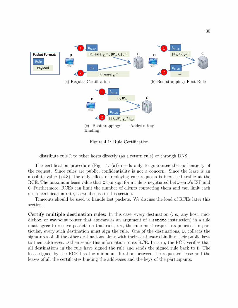
30
[R, lease] KD‐1 , [IPD,KD] KT
‐1
1
D CPacket Format:
RD→C
2 [R lease] ‐1
RDPayload
Rule
2 [R, lease] KC1
(a) Regular Certification
[IPD,KD] KT‐1
1
D C
RD→C
2RC→D
―
(b) Bootstrapping: First Rule
1
KD, IPDD C
RD→C
2 [ [K IP ] ‐1 ]
RC→D
2 [ [KD,IPD] KC1 ] KD
(c) Bootstrapping: Address-KeyBinding
Figure 4.1: Rule Certification
distribute rule R to other hosts directly (as a return rule) or through DNS.
The certification procedure (Fig. 4.1(a)) needs only to guarantee the authenticity ofthe request. Since rules are public, confidentiality is not a concern. Since the lease is anabsolute value (§4.3), the only effect of replaying rule requests is increased traffic at theRCE. The maximum lease value that C can sign for a rule is negotiated between D’s ISP andC. Furthermore, RCEs can limit the number of clients contacting them and can limit eachuser’s certification rate, as we discuss in this section.
Timeouts should be used to handle lost packets. We discuss the load of RCEs later thissection.
Certify multiple destination rules: In this case, every destination (i.e., any host, mid-dlebox, or waypoint router that appears as an argument of a sendto instruction) in a rulemust agree to receive packets on that rule, i.e., the rule must respect its policies. In par-ticular, every such destination must sign the rule. One of the destinations, D, collects thesignatures of all the other destinations along with their certificates binding their public keysto their addresses. D then sends this information to its RCE. In turn, the RCE verifies thatall destinations in the rule have signed the rule and sends the signed rule back to D. Thelease signed by the RCE has the minimum duration between the requested lease and theleases of all the certificates binding the addresses and the keys of the participants.

31
Certify rules invoking functions: Operators providing router functions can restrict whichrules can invoke these functions. The certification process is similar to certifying multipledestination rules. The identifiers of functions whose invocation requires authorization arerepresented as hashes of public keys. RCEs certify a rule containing such an invocation onlyif the rule is signed with the private key corresponding to the function identifier.
Bootstrapping: To certify rules, client D must contact an RCE. Recall that the ISP providesD with a rule to access an RCE, C. In addition, D needs to provide C with a return rule.Otherwise, C cannot send the certified rule back to D, since RBF requires every packet tohave a rule. The question is how can D get its first rule certified by C, without having areturn rule in the first place?
To get around this challenge, D asks C first to certify a rule that allows C to send packetsback to D, e.g.,
RC→D :i f ( packet . source == C)
sendto D
Upon receiving such certification request, C certifies it and sends the certificate back usingthe certified rule itself, RC→D. If the certification request has no return rule, C simply sendsthe certificate back using the certified rule. Fig.4.1(b) illustrates the first rule’s certification.
Recall that when sending a rule certification request, client D also needs to provide theRCE C with a certificate issued by a trusted authority, T, which signs the binding betweenD’s key KD and its address IPD. In general T can be any authority trusted by C. For example,T can be the ISP that provides service to D. For simplicity, in this dissertation, we assumethat T is also an RCE and, in particular, that T and C are the same.
Fig.4.1(c) shows how client D obtains a certificate of the binding between its address andpublic key. First, D sends to C a request containing only KD and its address IPD with noreturn rule (at this point D has no rule). Upon receiving this request, C signs the bindingbetween KD and IPD, and encrypts it with KD to guarantee D indeed owns the private keyK−1
D . To return this packet to D, C creates a rule with the same content as RC→D, but unlikeRC→D, this rule is named using one of C’s keys and not D’s key.1 The lease of the bindingalso represents a contractual agreement between the D’s ISP and the RCE C.
This procedure for obtaining the binding between a public key and an address, relies onthe fact that D is indeed the actual owner of IPD. A malicious router on the reverse pathfrom C to D or another host2 that can spoof D’s IP and can intercept its incoming packetscould make such requests for IPD. These attackers can forge rules named with their keysthat send traffic to victim D’s IP. We discuss this attack in more detail in §5.
1Note that in general, an RCE can always contact a host by just creating a rule to its address.2E.g. a host on the same wireless network as the victim.

32
Source Rules: We note that there is no difference in the certification procedure betweenrules logically imposed by sources and those of destinations.
RCE load and availability: To control its certification load, an RCE can rate-limit thenumber of certification requests that it processes from each individual client. Clients areidentified by IP address; the anti-spoofing mechanism prevents clients from impersonatingeach other. Alternatively, clients can be identified by the “personalized” rules provided bythe ISP to each customer to access the RCE; such rules may have a finer granularity thanthe anti-spoofing mechanism. RCEs can indirectly protect themselves against link-level DoSattacks by controlling the number of clients under contract.
RCEs must be highly available to enable rule certification at any time. RCEs can meetthis requirement by using multiple servers and multiple sites. ISPs and destinations canprotect themselves against RCE unavailability by contracting with multiple RCEs.
Automatic rule agreement: A host or middlebox appearing in a rule with multipledestinations needs an automatic way to check if it agrees with the rule, in the case whenthe rule was created by one of the other destinations. We expect an out-of-band processby which operators of middleboxes decide which sources/destinations they are willing to actfor and the nature of acceptable rules (lease durations, other middleboxes, etc.). Given thispredetermined information, a rule participant M can automatically check if it agrees with arule created by another rule participant by verifying the following properties: (1) only sourcesagreed by M are allowed to send packets on the rule, (2) the rule lease does not exceed M’sdesired duration for the rule. Optionally, some participants may verify whether certaindestinations are reached after themselves; e.g., middleboxes may want to verify whetherpackets are indeed going to the desired destination afterwards. These properties are verifiedby statically analyzing the rule. We leave implementing such tools to future work (see §10).
RCE Key Distribution and Revocation: In this dissertation we do not explore solutionsfor the distribution and revocation of RCE keys to routers. Here, we simply mention twopossible approaches towards this goal. In one approach, RCE keys could be distributed andrevoked using DNSSEC. For example, in the txt or other RR type, one DNS entry containsthe number of RCEs and, for each RCE, there is one DNS entry (based on its index suchas “ID24.rce”) that contains the RCE’s key. Routers periodically update the RCE keys. Inanother approach, RCEs could be deployed along AS boundaries, such that each AS wouldhave its own RCE. This approach has the advantage that additional security can be enforced,e.g., the trust in some RCEs can be restricted to their own address ranges. Secure BGP canbe used to distribute RCE keys in this case, but at the expense of extra complexity.3
3Note that DNSSEC could also potentially be used to distribute keys when RCEs are deployed along ASboundaries.

33
RCEDNS
S D
B
2
1 A
S D2
(a) Regular Distribution
E RCEDNS
S D
1 2 3 4
5S D
6
(b) DoS protection (Throttling Entity)
DNSE + RCE
S D
1 2A
3S D3
(c) DoS protection (Throttling Entity+ RCE)
Figure 4.2: Rule Distribution(solid lines = rule lookup process; dashed lines = data communication; dotted lines = setup)
4.2 Rule Distribution
RBF uses an extended DNS infrastructure to distribute rules, as illustrated in Fig. 4.2(a).The destination D creates and certifies a rule for itself (step A) and inserts it into the DNS(step B). A sender S that wants to contact D looks up D’s name in the DNS; the DNS isextended to return D’s rule rather than its address (step 1).4 After obtaining a rule to D, Sdirectly sends packets to D (step 2).
For practical purposes, the rules of the DNS root servers should have long leases or neverexpire. In this way, tedious reconfigurations or refresh protocols are avoided, similar to howtoday DNS root servers have long-lived addresses.
In Section 3.3 we pointed out that rules can be used to block DDoS attacks. This relieson (1) the ability to distribute customized rules to different senders (i.e., give a sender S
a rule that drops all packets not generated by S) and on (2) the ability to protect the ruledistribution itself from DoS attacks. We discuss distribution mechanisms to achieve thesenext.
4For example, DNS could be incrementally extended with a new type of record to serve rules rather thanaddresses.

34
4.2.1 Distributing Rules for DDoS Protection
To protect against DDoS attacks, client D can contract with a large entity E, and redirectits DNS entry to E, by registering E’s rule under its DNS name. Fig. 4.2(b) illustrates thisapproach. DNS will reply to a lookup for D’s name with E’s rule (step 1). The DNS entrythat contains E’s rule must belong to a new type of DNS RR. This new class of entries isreturned directly to clients by DNS resolvers. Upon a receipt of such an answer to its DNSquery, the requester will continue the DNS lookup by contacting E (step 2). E rate-limitsrule requests and forwards them to D (step 3), thus protecting D from DoS attacks. For theauthorized requesters, D creates rules (step 4) and replies back to the requesters (step 5). E
forwards requests to D conforming to a policy (see §3.3), which can be updated by D at anytime.
Note that some malicious users may still get their requests forwarded by E and authorizedby D. To alleviate this attack, E can employ fair queuing across senders, and D can blacklistknown attackers at E. Such an approach offers a protection similar to network capabilitiesthat apply per-source fair queuing at routers [78].
Fig. 4.2(c) presents an alternative solution, in which E directly creates rules for requesters.In this case, E has to incorporate the functionality of an RCE. To enable E to generate ruleson its behalf, D provides it a rule template parameterized by the requester’s address (step A).For example, the template could be similar to the rule for protecting against DoS presentedin §3.3: if (packet.source != <requester>) drop; else ...; E uses this template togenerate a unique rule per client. Upon receiving a lookup request from client S, E replacesthe <requester> template parameter with S’s address(es) extracted from S’s return rule,and sends the newly created rule to S (step 2). In addition to the rule template, D informsE of a rule granting policy, which also contains the maximum number of active rules E cangrant at a given time. If under attack or heavy load, D informs E to stop granting new rules,to reduce the maximum number of rules it can grant, or to block specific clients.
Compared to the approach presented in Fig.4.2(b), the solution from Fig.4.2(c) avoidsinvolving the destination in the rule certification process; however, it requires some of theRCEs to be able to withstand DoS attacks (those that provide this service) and may requiremore frequent policy updates between D and E.
Typically, to avoid the limitations of using middleboxes that should be on both theforward and reverse paths (see §8.3), the rules created to protect against DDoS attacksshould allow packets generated from all the addresses expressed in the requester’s rule.
4.3 Rule Leases
The lease is an expiration time stamp certified along with the rule description. A routerdrops a packet if its current time exceeds the rule expiration time.
To implement leases, we propose that all routers and RCEs are synchronized, via NTP

35
[26] as recommended by router manufacturers [32]. In this context, a lease is an absoluteexpiration time value (see Section 6.1 for details on our implementation).
In the absence of global clock synchronization, we next describe an alternative solutionin which lease times are relative to the RCE.
4.3.1 Alternative Lease Mechanism Not Using Global Synchro-nization
At a high level, each router maintains one timer per RCE and the current time at routersis set and updated from the flowing packets. For this purpose, rules also have associated acreation time besides the lease expiration time.
Each RCE associates to each certified rule two time stamps: a certification time cer time,and an expiration time exp time (when using NTP only the expiration is required). Thetimestamps are relative to the time of the RCE certifying the rule.
Each router maintains a clock tC for each RCE C. tC advances at the router’s internalclock rate. tC is initially in an uninitialized state and is initialized to the cer time value ofthe first forwarded packet that is certified by C.
Upon receiving a packet certified by C with certification time cer time, the router updatestC as follows:
tC = max(tC , cer time) (4.1)
In other words, the current time estimate for RCE C is set to the most accurate value; ifthe cer time is higher than tC it means that the current time estimate is behind the actualtime of RCE C and it should be updated (the rule is seen as certified in the future).
Routers drop expired packets, i.e., packets containing an exp time greater than thecorresponding tC . This ensures that in the absence of clock drift between the router and theRCE, and in the absence of router failure, a rule can be used for at most its lease period,i.e., exp time−cer time.
To protect against clock drifts that cause tC to increase faster than the RCE time, therouter resets tC (marks it as uninitialized) if it has not been updated for a predefined intervalof time I (e.g., several hours or days). In particular, the router resets tC to the largestcer time of any rule (certified by that RCE) that the router has seen during interval I. Weassume that clock drifts between any router in the Internet and any RCE are bounded by asmall value D within the interval I, such that D is much smaller than rule leases, e.g., D issmaller than one second.
Finally, note that rules of unpopular RCEs could potentially be replayed by malicioushosts (unpopular RCEs are those whose certified rules do not travel for long periods of timethrough the network). However, we expect unpopular RCEs to not exist in practice, giventhat collocated destinations of one ISP should typically be certified by the same RCE, andthus all packets going to that ISP should use the same router timer. Moreover, even ifunpopular RCEs would exist, given that no traffic is being sent to the particular destination

36
whose rules are replayed, the incentives for the attacker are small; more specifically, since noclients are accessing the destination, there are almost no incentives for DDoS attacks.
4.4 Anti-spoofing mechanism
If a source can spoof addresses on packets it sends, it can send packets to a destination D evenif the rule does not allow it to, and in this way evade D’s policy. Moreover, one can mounta DDoS attack by using a single rule distributed by a malicious source to a set of colluders.To address this problem, RBF can use a previously proposed anti-spoofing mechanism. Inthis dissertation, we propose the use of ingress filtering, which is already deployed by over75% of today’s ASes [39]. When deploying RBF, RBF routers could also be used to applyingress filtering. Note that if malicious ASes do not apply ingress filtering, DoS protectionis not fully compromised as only hosts in these ASes can launch attacks.
Instead of ingress filtering, RBF could leverage other anti-spoofing mechanisms suchas Passport [77]. However, Passport [77] requires a secure routing layer and incurs extraoverhead in packets.
The anti-spoofing mechanism requires middleboxes and routers that change a packet’sdestination address also to change the packet’s source address attribute.
Finally, note that RBF can function even with a partially deployed anti-spoofing mech-anism, such as the currently existing ingress-filtering. The default-off nature of RBF scalesdown the bots available to attackers since it reduces the spreading potential of viruses(e.g., viruses cannot perform random scanning because they have to know a rule for thecontacted destination). Moreover, a DoS attack will stop once the lease of the rule expires;the victim can detect the attacker, and stop providing new rules to it for a period of time.To detect attackers in this case, destinations can use a rule to record routers on the path(i.e., such as the the Pi [107] example in Section 3.3.) In addition, RBF could be used toincentivize the deployment of ingress filtering; destinations under attack can simply denyrules to requesters from ASes known not to ingress filter (e.g., which can be learned throughan independent service).

37
Chapter 5
Security Analysis
The RBF design aims to achieve the following three goals: (i) policy enforcement –ensure that the authorized rules respect the policies of all participants (routers, middleboxes,destinations), and packets with unauthorized rules are dropped inside the network; (ii) ruleenforcement - rules cannot be used by malicious senders and, if senders or rule participantsare untrusted, respect of rule directives can be enforced; and (iii) rule safety rules cannotbe used to attack the network. Next, we summarize RBF’s security properties, the threatmodel and assumptions under which they hold, and the mechanisms that allow RBF to meetthese goals.
Assumptions: We assume that DNS resolution is secure, that distribution of RCE keys torouters is secure, and that RCEs are not malicious.
Attackers: An attacker in RBF can be any host, middlebox, or router: sources can attemptto attack destinations by forging, evading or tampering with their rules; destinations cantry to attack the network by creating rules that waste resources and slow down routers;middleboxes and routers can attempt both of these attacks.
5.1 Security Properties
We decompose the aforementioned security goals into four specific desired properties:
1. No Rule Forging: A host S cannot manufacture a rule that sends packets to anotherhost D, unless D explicitly agrees with this rule, i.e., destinations and middleboxescontrol the creation of rules that send traffic to them.
2. No Rule Tampering: Sources, routers and middleboxes cannot tamper with thedestination’s rules.

38
\Mechanisms Certifi- Lease Anti- StaticProperties\ cation Spoofing AnalysisNo Rule Forging × ×No Rule Tampering ×No Rule Evasion × ×Network Safety × ×
Table 5.1: Properties and Defense Mechanisms
3. No Rule Evasion: Host S cannot send packets to destination D, if D’s rules do notaccept packets from S.
4. Network Safety: A destination D cannot create unsafe rules. In particular, D cannotcreate rules that (a) cause infinite loops, (b) corrupt router state, (c) DoS routers orRCEs, or (d) violate ISP policies.
5.2 Mechanisms
RBF uses four mechanisms to achieve the above properties:
1. rule certification
2. rule leases
3. anti-spoofing
4. static analysis.
Next, we discuss how these mechanisms achieve the four aforementioned security properties.Table 5.1 summarizes this information at a very high level.
5.3 Analysis
Rule Forging
To forge a rule that sends packets to an address IPD of a destination D, an attacker has tobe able to receive packets addressed to IPD as well as to send spoofed packets as originatedat IPD. The set of attackers in this category are mainly represented by the routers on thereverse path from the RCE to D. However, note that such attackers can already disrupt D atthe routing level (e.g., routers can drop/amplify packets to D, can insert malicious routing

39
updates such that packets do not reach D, etc.). Furthermore, using forging rules to mounta DoS attack is not easy. A malicious router creating a rule pointing to D would need toemploy a set of colluders to which it can distribute the rule, and then have these colludersDoS the victim. In the absence of such colluders, the malicious router can only use the ruleto send itself packets to D. Finally, the victim can detect the attack by checking whether ithas authorized the rules used by the packets it receives. This also means that a maliciousrouter M cannot deceit D into using rules created by M that allow M to eavesdrop packetssent to D, i.e., rules in which M is imposing itself as an unwanted middlebox. If D does notrecognize the rules it can immediately contact its ISP.
Based on these considerations, we believe that the possible rule forging attacks are rela-tively benign. Still, if needed, these attacks could be prevented by (a) having ISPs uploadto the RCEs the binding between the IP and the public key of their customers, or (b) byhaving the ISPs themselves sign the binding between their clients’ addresses and their keys(e.g., through an extended DHCP like service). For example, in our presented approach,a large enterprise could protect against malicious routers forging rules to its addresses byhaving its ISP upload its public key to all RCEs, together with its address prefix.
Even though an attacker cannot forge a rule, it may still be able to send packets to ahost which did not approve the rule. Assume the address of host D changes from IPD to IP′D,and that IPD is immediately assigned to host X. If D grants a rule to host A, then A can usethe rule to send packets to host X once the address has changed. However, we argue thatthe impact of such attack is negligible. First, the attacker can use the stale rule only for theduration of its lease. Second, the attacker cannot influence the selection of the new addressowner, so it cannot pick its victim.
Rule tampering
The fact that rules are signed prevents any router or middlebox along the path to tamperwith the rules.
Rule evasion
Host A can attempt to elude D’s rules by (a) spoofing its address, (b) mounting a replayattack, or (c) using a reflection attack.
The anti-spoofing mechanism employed by RBF precludes an attacker (e.g., A) fromspoofing its address.
The lease mechanism mitigates the replay attacks, by limiting the ability of A to use therule beyond the time intended by D.
Finally, an attacker A can indirectly send packets to a destination D by sending packetsto a reflector R with a return rule pointing to D. D can defend against receiving reflectedpackets by specifying in each of its rules the sources that are allowed to send packets on thatrule. Unless R is in this set, the routers will drop the packets reflected by R. A sophisticated

40
attacker might attempt to find rules that the victim D uses to communicate with R. If R isa large entity (such as Google), the attacker might have the opportunity to mount a DoSattack on D. However, to find such rules the attacker would typically need to collude withcompromised routers on the paths between R and D, which can most likely already harm D
as discussed earlier. In addition, R can detect whether the other communication endpointdoes not send meaningful responses (the attacker does not receive any traffic back) and candetect such attacks.
Network safety
D can attempt to create rules which (a) cause infinite loops, (b) corrupt router state, (c)DoS routers, and (d) violate ISP policies. Furthermore, D may also attempt to (e) DoS theRCEs. Next, we consider each of these attacks in turn.
Infinite Loops – A rule could potentially create a forwarding loop by changing the packetdestination in a circular fashion (the packets using such a rule would be dropped only whentheir TTL expires). To protect against such attacks, RCEs use static analysis to checkwhether the rule may cause forwarding loops. In Appendix A, we present an algorithm,called Loop-Free Rule (LFR), that detects forwarding loops, and we prove the followingresult:Theorem: A rule cannot create forwarding loops if it is validated by the LFR algorithm.
Similarly, in Appendix B we present an algorithm that detects rules that can lead toinvocation loops, i.e., the packet keeps invoking functionalities at one router.
Importantly, note that both these types of attacks (that form loops) can be avoidedthrough runtime mechanisms (see Appendices A and B). However, we take advantage of therule certification and keep the forwarding mechanism simple by using static analysis.
In a nutshell, to detect loops, it suffices to verify whether the finite state machine (FSM)modeling the rule execution has cycles containing one or more destination addresses. Thestates of the FSM are of the form <packet.attributes, router.attributes>. While given a ruleit is easy to find the transitions between these states, the number of states can be large.Fortunately, the rule structure is very simple, and rules only allow comparison operationsand assignments. This allows us to use a highly simplified version of symbolic-execution [75]to reduce the number of states to that of the number of destinations in the rule.
On the data plane, a malicious router can induce loops by changing the packet state. Forexample, a packet that has just visited a middlebox can be turned back to the middleboxby resetting its state to that before the middlebox. However, note that this attack doesnot represent an infinite loop since it requires the attacker to process the packet every timeit comes back. For rules that filter out source addresses, the anti-spoofing mechanism canprevent most of these attacks because the router cannot send packets back to the middleboxwhile pretending to be the source.
Router corruption – The rule forwarding logic is simple enough so that we can assumethat routers implementation of this logic is correct. Together with the fact that rules cannot

41
modify router attributes, this guarantees that rules cannot compromise router state.Attackers might also try to corrupt routers by exploiting errors in the invoked router
functionalities. However, routers can use techniques such as virtualization [12,51] to protectagainst such attacks.
DoS Routers – With RBF, an attacker can attempt to slow down routers by sendingpackets with random certificates, causing the router to waste time verifying these bogussignatures. RBF routers can simply blacklist such attackers. Moreover, this attack can onlyoccur at the first RBF router. For this reason, the incentives for it are low, as the attackerends up targeting its own access route and, at most, other collocated users. The attack canfurther be alleviated by having two forwarding paths, a fast path for the already verified andcached certifications, and a slow path for first time rules. A more sophisticated version ofthis attack may use a large number of valid rules instead of random certificates. This attackis both more difficult to mount and to detect, and can be mitigated by placing a cap on therate of new rules per host.
Another DoS attack on routers is to use rules that take a long time to forward. However,the rule forwarding time is directly proportional with the rule size, which is bounded.
Attackers may also attempt to slow down a router by extensively invoking the function-alities it exposes. In fact, there is a broader question about how one should architect routerimplementations to accommodate functions invoked by end users and, in particular, to makesure functions do not open additional vulnerabilities through resource exhaustion attacks.While a comprehensive treatment of this question is an active research topic [41, 53, 113]and beyond the scope of this dissertation, in Sections 6.1 and 6.2 we present and evaluate aprototype software router that offers isolation between the plain forwarding traffic and trafficinvoking functionalities as well as isolation between different functionalities.
Path violation – Malicious hosts can create rules which violate ISP routing policies.For example, two colluders A and B could create a rule as follows: the packet leaves thesource towards A but when reaching a certain AS or router (before reaching A), it suddenlychanges the destination to B. In this way, with multiple colluders, arbitrary AS path couldpotentially be selected. To prevent such a malicious behavior, RCEs may use static analysisto guarantee that the destination attribute is not changed before the packet reaches thecurrent rule destination.1
DoS RCEs – By sending certification requests at a high rate, attackers may attemptto indirectly attack other destinations by slowing down their RCEs. However, RCEs cancontrol the number of destinations that use them and rate-limit the certification requestfor each destination (§4.1). Moreover, to improve availability, each host can use multipleRCEs. Malicious routers may also attempt to replay a destination’s certification requests ata high-rate in an attempt to prevent it from certifying new rules. However, this does notrepresent a new attack ability for malicious routers, which can already drop any packet of
1Similarly to the case of infinite loops, this attack could be prevented by restricting the rule forwardingmechanism, but we again take advantage of the already existing certification.

42
that destination, just as they can also drop the certification requests.Source Rules – Given that the control from the destination rule is never returned to the
source rule, each packet containing a source rule can be considered as two distinct packets:one using the source rule and one using the destination rule. Thus, the use of source rulesdoes not create any new threats compared to having a single rule in packets. Note thata source rule is just as any other rule and must have at least one destination (middlebox,indirection router, etc.). In order to prevent the path violation attack described before, theattribute that switches the control from the source rule to the destination rule can be setonly when arriving at one of the destination addresses specified in the source rule.

43
Chapter 6
Evaluation
6.1 Implementation
This section describes our prototype RBF router and rule compiler.
6.1.1 An RBF Rule Compiler
Our prototype implementation offers users a high-level language in which to write rules,language that is largely identical to the rule syntax used in this dissertation. We wrote anRBF compiler in C++ that translates this high-level language into a compact rule formatcarried in packets. This compact format uses the following types of statements: drop,sendto address, set the value of a packet attribute, compare attributes (with values orbetween them), jump to a forward statement (always or on false/true conditions) and invoke
a router-defined function. The compare statement sets a flag depending on the result of thecomparison, which is used by the jump statements (the flag is initialized with zero at the startof the rule). The jump statements can only take positive offsets. To reduce the size of rules,we use variable-length encoding in representing the internal rule structure. We also use:8B(ytes) for public-key hashes, 3B for the user-local index (contained in the rule identifier),3B to identify the RCE, 3B to identify router-defined functions that do not require approvalto be invoked and 8B for those that do, and 2B as the default RBF packet attribute values.1
For the lease we use an absolute expiration time consisting of first 4B of the NTP format,with second-level granularity and a wrap-around period of 136 years. The maximum ruledescription size is 256B in our implementation.
1Our current prototype only supports this default size.

44
6.1.2 A Prototype RBF Router
Rationale: We implemented RBF forwarding using Click [83] and RouteBricks [48]. Mostcommercial routers implement packet processing using ASICs or specialized network proces-sors (NPs) rather than general-purpose CPUs and, as such, our software-based prototype isnot entirely representative of currently deployed routers. To a large extent, our choice of pro-totyping platform is borne of necessity since commercial routers are closed. Beyond necessity,however, we believe a software-based prototype is valuable for multiple reasons. First, recentresearch [48,50,65] has demonstrated that, with modern multi-core servers, it is now possibleto build high-speed software routers up to edge and even core speeds. Secondly, while notdirectly reusable, several aspects of our implementation architecture such as our approachto partitioning tasks across multiple cores should apply to network processor-based routers.Finally, several research [23, 60] and commercial switches [8] augment ASIC-based switcheswith some number of co-located general-purpose cores or servers for greater flexibility inpacket processing – our prototype architecture is directly applicable to such platforms.
Design requirements: We build our prototype in the context of modern multi-core serversthat incorporate multiple processors or “sockets”, each with multiple cores [5,29]. As shownin Fig. 2.1, the software stack of an RBF router includes the following key components:(1) an IP forwarding module, (2) the rule execution engine, and (3) some (possibly zero)number of specialized forwarding function modules. All packets traverse the rule executionand IP forwarding components, while different subsets of packets may traverse one or morespecialized functions. In addition, the resources required to process a packet may varywidely across functions; e.g., an encryption function would use lots of CPU but little cache,while a caching module may use more cache and less CPU. At a high level, our design goalis to balance high performance (i.e., making efficient use of resources) with performanceisolation, both across different functions, and between functions and the rule execution engine(i.e., sharing resources in a fair manner).
Approach: In its full generality, the above goal requires contention-aware scheduling thatsimultaneously takes into account the multiple resources (cores, various caches, memorybandwidth, I/O bandwidth) for which tasks might contend. For modern multi-core systems,this is in itself an area of active research [41,113] and beyond the scope of this dissertation.Instead, in our prototype, we address the issue as follows. The IP forwarding module andthe rule execution engine are the central, most critical, components of the router and hencewe assign these to a socket of their own and do not run specialized functions at cores inthis socket. This avoids having the IP and rule execution engines contend with specializedfunctions for cache, CPU and other resources at the cost of some potential inefficiency sincethese “reserved” cores (if unused) cannot be used by specialized functions (if needed). Wethen assign specialized functions to the remaining “unreserved” cores. We rely on the existing(Click and Linux in our implementation) system schedulers to ensure fair sharing of CPU

45
Kernel Kernel User level
RBF + IP
RBF + IP
RBF + IP
RBF + IP
Multicast
Firewall
Multicast
Firewall
Caching
IDS
Cacning
IDS
M M C C
Socket 0 Socket 1CPU Cores
Figure 6.1: Core Allocation Example in RBF Router
resources between functions on the same core.To achieve high performance, we run a single thread performing both IP forwarding and
rule execution at each of the reserved cores; this ensures that packets that do not invoke anyspecialized functions are processed entirely by a single core avoiding potentially expensivecache misses and inter-core synchronization [48]. Packets that invoke specialized functionsmust be relayed across cores and hence incur corresponding performance overheads due tocache misses and so forth. To improve the efficiency of such transfers when these functionsare implemented in user space, we use shared memory pages and event queues. An exampleof the resulting system architecture is depicted in Fig. 6.1.
6.2 Evaluation Results
We use our prototype to evaluate the overhead RBF imposes on packets (§6.2.1), routers(§6.2.2) and RCEs (§6.2.4).
6.2.1 Packet Size Overhead
Fig. 6.2 presents rule sizes (in bytes) for a range of examples, including those from §3.3.The figure captures all the RBF-related fields and presents the size broken down into (a)the rule and the associated attributes’ binary encoding; (b) the control fields used for thelease, RCE identification, to specify whether the return rule is in the packet, whether thepacket has a source rule, and so forth; and (c) the rule signature. We assume a 41B signatureobtained using ECDSA with ECC public keys for RCEs derived from the NIST B-163 orK-163 curves [30], offering 80 bits of security. Note that RBF is independent of the exactsignature scheme used and that smaller (and faster) signatures can be used. However,shorter RCE keys may require more frequent updates to compensate for the lower security

46
0
20
40
60
80
100
120
140
Bytes
Rule Encoding Control Signature
Figure 6.2: Rule Sizes
guarantees. The rules in Fig. 6.2 do not contain an identifier, and are identified by endpointsand routers using a hash over their content. Rule identifiers are required for rules whosecontent may change during a communication (such as the rules of mobile hosts) and incursan additional 11B overhead in our implementation (8B for the hash of the public key and 3Bfor the user-selected index). Note that the rule identifier need be unique only with respectto a single communication endpoint (i.e., all parties that a host X communicates with shouldhave unique rule identifiers).
From Fig. 6.2 we can see that many common forwarding scenarios (unicast, routing viamiddleboxes, rules for DoS protection) can be expressed with around 60-80B rules whilemore complex rules (e.g., loose source routing, secure middleboxes, anycast) can take asmuch as 140B. The average rule size across all examples we have implemented is 85B, rep-resenting 13% overhead for an average packet of 630B [9] and 6% overhead for a 1500Bpacket. By comparison, using RSA-1024 signatures (instead of ECDSA) would incur 27%overhead on a 630B packet and 11% overhead on a 1500B packet. Note that the packet sizeoverhead matters mainly when links are congested, in which case the goodput (application-level throughput) of the participants to the traffic is reduced proportionally with the RBFoverhead.2 Links usually get congested when many endpoints use throughput-intensive ap-plications. Since throughput-intensive applications typically use large packets, we expect
2The added latency due to the additional per-packet overhead is minimal.

47
the observed goodput reduction to be in practice closer to the overhead associated withlarge packets rather than average-sized packets. Moreover, we expect this overhead to besignificantly reduced in the future with the adoption of jumbo frames.
Potential Optimization - Rule Caching: Per-packet overhead can be significantly re-duced by caching rules at endpoints and routers; packets whose rules have been cached needonly carry rule identifiers. There are two opportunities for caching. First, destinations cancache return rules; this allows the return rule to be eliminated from all but the first packetin a source-to-destination exchange. Second, rules can also be cached at routers. Here, how-ever, we must ensure no packet carrying only a rule identifier arrives at a router that doesnot store the corresponding rule description. This might occur, for example, due to a routechange or when a router deletes the rule from its cache. In such cases, the router can simplydrop the packet in question, if the endpoints include the rule on all retransmissions andduring periods of high packet loss. Of course, caching imposes additional storage overheadat routers as we evaluate shortly.
In summary, based on our evaluation, we see that the per-packet overhead due to RBF canrange from as low as 24B when using caching and up to ∼250B in the bad case where thereis no caching and the packet carries complex destination and return rules. Sources can addtheir own control for outgoing packets through source rules, at the expense of an additionalrule in the packet. In general, the more endpoints take advantage of the flexibility offeredby rules, the higher the overhead. Based on their interests, endpoints can select differentpoints on this tradeoff between flexibility and overhead.
6.2.2 Router Overhead
In this section, we evaluate the overhead RBF imposes on routers for rules that do not invokespecialized processing functions; we consider router functions in the following section. Theprimary overhead RBF imposes on routers is the additional processing required to executeand authenticate rules and the additional storage capacity required if rules are cached.
Rule Forwarding
We first measure the overhead of rule processing by comparing the performance of RBF-on-RouteBricks to that of unmodified RouteBricks running on a single high-end server machine.We use a dual-socket server with four 2.8GHz Intel Xeon (X5560) cores per socket to (from)which we generate (sink) traffic over two dual-port 10G NICs. In this experiment, we useall 8 cores to forward packets and do not perform rule authentication (i.e., the RBF routeris assumed to be inside a trusted domain).
Fig. 6.3 plots forwarding rates for some of the examples from Fig. 6.2. The first columnrepresents a packet stream with sizes generated based on a packet trace collected on theAbilene backbone [22]; since the packets from the trace do not have rules, we add to each

48
05
10
1520
2530
35
40
Gbp
s
RBF over RouteBricks RouteBricks alone
Figure 6.3: Forwarding speed for RBF over RouteBricks
packet the slowest rule that fits in the packet. By “slowest” we mean the rule that takes thelongest time to forward, as determined by the number of conditions and actions encounteredduring forwarding. To capture the performance impact for small packets, we profile eachrule without any payload and with no return rules. In the figure, packet sizes are shown nextto the example name and entries are sorted in order of increasing packet size; the packetsize also includes the Ethernet and IP headers. The last columns depict forwarding of largerpackets, i.e., that also contain data payload. To see the impact of the type of rule for thesepackets, we profiled them with the fastest and the slowest rules. Note that all rules areprofiled in the worst case, meaning that the longest path through the rule is considered. Forthe slowest rule we use a 145B anycast rule which selects one out of 10 destinations basedon the value of a packet attribute (the last destination is always selected in our tests to usethe longest path in the rule).
Overall, we see in Fig. 6.3 that the performance degradation due to RBF’s more complexper-packet processing is always modest (<15%) and virtually non-existent at larger packetsizes. For small packets the CPU is the forwarding bottleneck, and RBF’s added processingslows the router. For larger packets the I/O system is the bottleneck, and there are enoughfree CPU cycles to execute rules. A fine-grained profile of the rule execution module showedthat it uses between 120 CPU cycles per packet for the fastest rule and 600 CPU cyclesfor the slowest rule; in comparison, the IP router used in our experiments requires around3000 cycles per packet without rule execution. Also note that compared to the network-levelforwarding results from Fig. 6.3, application-level goodput is further reduced by the RBFheader.
RBF is also compatible with high-end routers that use specialized hardware, rather thanthe general-purpose x86 hardware we consider. Increasingly, high-end routers rely on network

49
processors [49,103] for data plane processing (e.g., Cisco’s flagship CRS router uses networkprocessors). We expect network processors can accommodate the flexibility RBF requiresin per-packet processing (since network processors are fully programmable, much like ourgeneral-purpose server but simply use a different programming paradigm) with a similartype of overhead.
Rule Authentication
Recall that routers must verify rule signatures. While signature verification is expensive,there are two reasons we argue this overhead is manageable. First, only routers at trustboundaries need to authenticate rules; border routers see lower traffic loads than core ones,and hence can more easily accommodate the cost of authentication. Second, routers cancache the results of authentication checks, maintaining a hash of the rule and signature.With caching, the full signature verification is only required for the first packet forwardedon a new rule, within a certain caching period. Thus verifications can be limited to onlyborder routers and, assuming a large enough cache, the rate of verifications is on the orderof the rate of arrival of packets with new rules.
In this dissertation we proposed the use of ECC signatures applied on rules and weare pursuing a hardware based implementation of RBF that uses ECC signatures. In themeantime, we have evaluated RBF with a software implementation of RSA which is moreamenable to software implementations (we have compared the packet overheads of ECC andRSA previously, in Section 6.2.1). New CPU hardware can handle thousands of public keysignature verifications per second. For example one core of the router machine that we usedto forward rules in the previous experiment can perform over 38k verifications per second forRSA 1024. Moreover, these verifications can be parallelized; if all the 8 cores of the routermachine are used, the machine can process almost 300k 1024bit RSA signatures per second.However, if the same hardware is used both to verify signatures and to forward packets, theextra processing required by authentication may slow down forwarding.
In Fig. 6.4 we evaluate the impact of rule verification on forwarding, using the same twomachine setup as before. On the X axis we show the percent of packets with rules beingauthenticated. For the rest of the packets (which are not authenticated), we assume therouter has cached authentication information, since those packets belong to flows alreadyestablished. Note that we ignore the cache lookup time. We use 1024 bit RSA keys. Todecouple the effect of rule processing from that of authentication, we profiled different packetsizes containing the slowest rule; to capture the impact of authentication for small packet,we also profiled this rule with no data payload. The vertical line at approximately 5% inFig. 6.4 shows the average rate of packets corresponding to new flows in the Internet; weextracted this rate from recent backbone traffic monitoring at [9]3 However, we think this
3This ratio represents the number of flows to the number of packets (i.e., the inverse of the flow lengthin packets). We use this value in this experiment because we fill up the entire available bandwidth. Asmentioned in §3, we have observed a rate of less than 1% when comparing the bandwidth used by packets

50
20
25
30
35
40
ps
5
10
15
20
25
30
35
40
Gbp
s
0
5
10
15
20
25
30
35
40
0 5 10 15 20 25 30
Gbp
s
% Packets Authenticated
Real Traffic (Abilene) 700B pkt 220B pkt 1500B pkt
0
5
10
15
20
25
30
35
40
0 5 10 15 20 25 30
Gbp
s
% Packets Authenticated
Real Traffic (Abilene) 700B pkt 220B pkt 1500B pkt
0
5
10
15
20
25
30
35
40
0 5 10 15 20 25 30
Gbp
s
% Packets Authenticated
Real Traffic (Abilene) 700B pkt 220B pkt 1500B pkt
0
5
10
15
20
25
30
35
40
0 5 10 15 20 25 30
Gbp
s
% Packets Authenticated
Real Traffic (Abilene) 700B pkt 220B pkt 1500B pkt
Figure 6.4: Forwarding speed when verifying packets.
rate represents a pessimistic estimate for average rate of packets with new rules seen bya router because multiple connections share the same rule, e.g., a client makes multipleconnections to a web server all sharing the same rule.
As we can see, authentication does impact forwarding as the CPU becomes the scarceresource. As expected, this impacts mostly the smaller packets. However, the rate for thepackets generated using real traffic data (Abilene) is not significantly impacted up to the5% threshold derived from the Internet’s average rate of new flows. Moreover, the goodnews is that by adding more cores, this process can be parallelized; current industry trendsseem to indicate that end-hosts as well as routers will increase their number of cores. Wethus expect a linear increase in performance as more and more cores are used, up to theforwarding results presented earlier in Fig. 6.3.4
Slowing down routers by purposely sending many valid new rules is difficult. First, theattacker has to find a large number of valid rules and use them before they expire. Forexample, assuming a 1 million rule cache, the attacker would have to find over 1 millionvalid rules. Second, routers can detect such behavior and block attackers, similar to theattack with random certifications described in §5. For example, a typical user is expectedto send packets containing only a few new rules per second. In addition, as mentioned in§5, the incentives to mount such attacks are not as high as, for example, DoS attacks, sinceattackers would have a short range of action. Essentially, attackers can only attempt to slowdown their access path and attack their own provider.
indicating new flows to the link capacity, because the link is not fully utilized.4In addition, historically, network speed has increased at a smaller pace than computational power (see
Nielsen’s law [18] vs. Moore’s law); accordingly, we expect such a trend to persist in the future, in whichcase, authentication will be more and more easy to perform at line speed.

51
% packets invoking Snort0 25 50 75 100
Gbp
s
0
5
10
15
20
Total inRegular inSnort in
Regular outSnort out
(a) Large Packet Trace
% packets invoking Snort0 25 50 75 100
Mpp
s
0
1
2
3
4
5
6
7
Total traffic inRegular inSnort in
Regular outSnort out
(b) Small Packet Trace
Figure 6.5: Performance Isolation Between Router Functions and Regular Traffic
Router cache sizes
We earlier proposed that routers cache rule authentications and/or even rule descriptions.In each case, the number of cache entries required depends on the number of distinct rulesthe router sees. If we assume that all packets in a flow share the same rule, then thenumber of distinct rules passing through a given router varies between the worst case ofO(#flows) to the best case of O(#destinations) seen by the router. The former correspondsto a destination that uses a different rule for every source it communicates with, the latterto a destination that uses a single rule for all potential sources.
In our implementation, each cached authentication is 19 bytes – 11B for the rule identifierand an 8-byte hash value used to verify whether the rule has changed since it was authen-ticated. Each router uses its own secret hash function to prevent attackers from using hashcollisions. Thus, one million rules would require only 19MB of memory. For caching entirerules, Fig. 6.2 reveals average and worst-case rule sizes of 85 and 133 bytes, respectively. Ifwe conservatively assume traffic is uniformly distributed across these forwarding categories,we arrive at an estimated cache size of 85MB (average) to 133MB (worst-case) for 1M rules,which is within the scope of memory available in current routers.
6.2.3 Router Functions
Our router prototype supports specialized functions implemented at either kernel-level oruser-level. We currently support three router functions: (i) the Snort IDS [24] adapted to

52
Input Rate Gbps0 5 10 15 20 25
Gbp
s
0
5
10
15
20
Firewall onlyEncryption onlyFirewall sharedEncryption shared
(a) Large Packet TraceM
pps
01234567
alon
e
shar
ed
alon
e
shar
ed
FirewallEncryption
50%
50%
(b) Small Packet Trace
Figure 6.6: Fairness Between Router Functions
run as a user-level function, (ii) a kernel-mode firewall implemented in Click and (iii) akernel-mode encryption engine also implemented in Click. Each function runs as a separateprocess/kernel thread isolated from the packet forwarding path through queues. We measureperformance and fairness using the above functions on the same hardware as before. Wededicate four cores to the standard forwarding path and the remaining four cores to customfunctions.
Fig. 6.5 illustrates the resource isolation between forwarding and router functions; thefunction used in this experiment is Snort (running on four cores). To generate traffic weuse real traces of malicious traffic created particularly for IDS testing [20, 64]. The averagepacket size of the trace used in Fig. 6.5(a) was 1065 bytes while in Fig. 6.5(b) was 195 bytes.To avoid biasing our results, we modify Snort not to drop any malicious packets so packetsare only dropped due to resource exhaustion. Our test maintains constant total input trafficwhile increasing the percentage of input traffic that invokes Snort (X-axis). We see fromFig. 6.5 that Snort traffic does not affect the “regular” traffic that does not invoke Snort,in the sense that no regular traffic is dropped, even as a growing percentage of input Snorttraffic is dropped.5
Fig. 6.6 illustrates isolation between router functions. We use two functions, firewall
5We also measured the performance of the system with all the eight cores running both forwarding andSnort, and all the packets directed to Snort. While this configuration does not provide isolation for theregular traffic, it can forward a higher total throughput of 22Gbps when using large packets.

53
and encryption, and we run three experiments: (1) all traffic invokes the firewall functionand no traffic invokes encryption; (2) all traffic invokes encryption; and (3) equal halves oftraffic invoking firewall and encryption. In the third (shared) test the CPU is shared fairlybetween functions (we use Click-level scheduling); thus, the ratio between the maximumthroughputs achieved by each router function is expected to roughly match the ratio betweenthe throughputs of the functions when running in isolation. Fig. 6.6(a) plots the resultingforwarding rates under increasing input traffic, when generating packets from a trace withan average packet size of 1065 bytes. Perhaps surprisingly, in Fig. 6.6(a) the encryptionthroughput is higher for a mix of firewalled and encrypted traffic than 50% of the throughputwhen encryption is executed alone. The reason is that the trace contains large packets. Inthis case, the CPU is not the bottleneck for the firewall functionality, but is the bottleneck forencryption (since it is more CPU-intensive), and thus encryption ends up using the leftoverfirewall CPU cycles. Fig. 6.6(b) shows this result when using a trace with very small packets– the average size is only 195 Bytes. In this case, both functionalities achieve around 50%of their throughput in isolation. In general, the high throughput achieved when runningeach function in isolation illustrates the benefit of running instances of a single function atmultiple cores, as opposed to one function per core, since this allows the unused resourcesfrom one function to be seamlessly utilized by other functions.
6.2.4 RCE Load
We use a simple back-of-the-envelope calculation to estimate the total number of RCE serversrequired for the Internet. The bulk of requests to RCEs are determined by IP address changesand per-client certifications requested by sites that protect against DoS (by redirecting DNSrequests to powerful entities, see §3.3,§4.2). Note that in the latter case, requests to RCEsare made only for approved customers. There are currently around 800 million hosts in theInternet [31]; for simplicity, we consider 1 billion hosts. We assume a worst-case scenario inwhich all hosts request certifications in the same second, i.e., these requests are made eitherby hosts individually or by DoS-concerned websites that hosts are trying to access. Weimplemented RCE rule certification in software using RSA signatures, and measured it onthe same 8-core server used throughout our evaluation. We find a single server can achieve acertification rate of over 16,000 rules per second. Based on benchmarks of our implementationand assuming an oversubscription rate of 10× (ISPs today commonly oversubscribe by 100×),the total load due to certifying rules above could be accommodated by around 6,000 servers;e.g., handled by 20 RCEs with 300 servers each. Hardware implementations might reduce thisnumber by more than an order of magnitude. For example, using recent ECC prototypes [70,112] a single ASIC could potentially perform 40,000 RCE certifications per second, requiringa total of only 2500 such devices.
54
Chapter 7
Related Work
RBF is inspired by and extends several directions in past research. At a high level,RBF’s contribution is in offering extensive flexibility while respecting policies, where priorapproaches tended to focus on one or the other. We next contrast RBF to a large bodyof work proposing more flexible or more secure network architectures. At the end of thissection we present a table summarizing most of the properties by which RBF differs fromother proposals. We then also show that key to RBF’s ability to provide both flexibility andpolicy compliance is a new division between the data-plane and control plane compared toprevious work.
RBF’s focus on flexibility in forwarding is, of course, similar to that of active net-works [101]. Where RBF differs is in constraining this flexibility—RBF forwarding directivesare simple if-then-else constructs rather than arbitrary code. And while RBF does accom-modate specialized functions at routers, we assume these are installed by network providers.Nor does RBF permit endpoints to introduce or manipulate router state (unlike, for example,schemes such as ESP [42]). Because of this constraint, RBF cannot support as complex formsof packet processing – e.g., RBF cannot support the forms of reliable multicast and multi-cast feedback thinning that ESP does. The flip side is that, because of RBF’s constraints onrules and because RBF mandates the use of these rules, it achieves greater security throughprovable rule safety and the ability to prevent unwanted traffic by default.
More generally, previous architectures that aim to provide flexible forwarding e.g., [37,42,78,86,90,98,101,104,106] can be divided into four classes based on whether end-users areallowed to (i) modify router forwarding state, or/and (ii) modify forwarding information inpacket headers (e.g., destination address):
1. Modify both router forwarding state and forwarding information in packet headers(e.g., most Active Network proposals [101], ESP [42]).
2. Modify router state but not packet headers (e.g., Active Networks focusing on “activestorage” [102]).

55
3. Modify packet forwarding information but not routing state (e.g., i3 [98], DOA [104]).
4. Modify neither router forwarding state nor packet state (e.g., IP). 1
RBF belongs to the third class above, which we argue provides the best tradeoff betweenflexibility and security. The first two classes allow data packets to modify router forwardingstate, which poses significant security risks. Indeed, at the limit, an application could imple-ment complicated distributed protocols (e.g., routing protocols) whose safety is notoriouslyhard to verify. In contrast, the last class offers limited flexibility, as end-users can exerciseno control on packet forwarding.
RBF is likewise inspired by the growing body of research advocating a default-off modelfor network connectivity [38, 43, 66, 72, 91]. What RBF adds is a focus on flexibility (unlike,for example, [38, 66] that only consider simple access control), extending this flexibility tothe wide-area (unlike [43, 72] that focus on enterprise or data-center environments) andin providing forwarding directives with end-to-end semantics (unlike [91]). Moreover RBFachieves the above without requiring the dynamic creation/teardown of state at routers(unlike [38]) or centralized policy entities (unlike [43,72]).
RBF also shares aspects of the work on capability-based architectures (e.g., [87,108,110])since rules are essentially capabilities. RBF uses capabilities/rules in all packets and (again)adds a focus on flexibility in forwarding, showing how endpoints can choose to incorporatemiddleboxes and router extensions, implement multicast, anycast, multipath routing and soforth. RBF also differs in the mechanisms adopted. In particular, RBF does not requiredifferent router-level treatment for control traffic, opting instead for a scalable distributedinfrastructure to alleviate DoS attacks on the control plane.
More generally, there are a vast number of proposals for DoS protection [37,47,68,78,79].RBF offers similar protection while introducing a focus on flexible forwarding. Fundamen-tally, RBF’s ability to offer flexibility is because rules are not bound to in-network state(unlike, for example, [37] or [68]).
RBF also draws inspiration from overlay-based architectures that aim to extend IP for-warding [34, 71, 98, 104] but instead operates at the network layer. This offers improvedsecurity (since RBF can block unwanted packets even if the attacker knows the target’s IPaddress) and the ability to influence path selection at the router-level.
NUTSS [61] employs on path middleboxes to provide control access, and off-path mid-dleboxes to implement per-domain on/off policies. Compared to NUTSS, rules in RBF areglobal, which allows RBF to block traffic closer to the source. In addition, RBF providesa more flexible data plane, and does not require inter-domain synchronization to supportfunctionality such as mobility.
RBF also adopts the philosophy of decoupling forwarding and routing proposed by path-pinning architectures such as Platypus [90] and SNAPP [86] but extends these for greater
1Of course, routers perform logging and monitoring tasks which change their state, and routers modifythe TTL value which represents state in packet, but here we refer to user-controlled forwarding abilities.

56
Property Architecture
Explicit Middle-box Support
Multi-ple Paths
Invoke Router Extensions (e.g. IDS, multicast)
Use Router State in Forwarding (e.g. anycast, DTN)
Record Router State (e.g. network probing, ECN)
Mobi-lity
Policy Compliant Loose Paths
Policy Compliant In-network Functionality Use
ReceiverReacha-bility Control
Host DDoS Protec-tion
Safety of Network & Routers (e.g. loops, break ISP policies)
RBF Yes Yes Yes Yes Yes Yes Yes Yes Yes Yes Yes Active Networks
Yes Yes Yes Yes Yes Yes No No No No No
ESP No No Yes No Yes No No No No No Yes i3, DOA Yes No No No No Yes No No No No Yes Platypus, SNAPP
Yes Yes No No No No Yes No No No Yes
TVA, SIFF No No No No No No No No No Yes Yes NUTSS Yes No No No No No Yes No Yes No Yes PushBack, AITF, StopIt
No No No No No No No No No Yes Yes
Predicate routing, Off-by-default
No No No No No No No No Yes No Yes
ICING Yes No No No No No Yes No Yes No Yes
Security / Policy Compliance Flexibility Available to End-hosts
Figure 7.1: A comparison of RBF to: Active Networks [101,105], ESP [42], i3 [98], DOA [104],Platypus [90], SNAPP [86], TVA [110], SIFF [108], NUTSS [61], PushBack [68], AITF [37],StopIt [78], Predicate Routing [91], Off-by-default [38], ICING [93]
generality in forwarding.Karsten et al. [74] propose an axiomatic model for network communication. The for-
warding primitives used in [74] differ from rules in two ways. First, RBF can modify thepacket header (attributes) in a more general way than the axiomatic model that only sup-ports packet encapsulation. Second, RBF does not allow packet replication for safety andmanageability reasons. Note that both RBF and [74] do not enable the forwarding processto modify state at routers.
RBF is complementary to recent efforts proposing open router APIs [27, 28, 81] – weoffer an overall network design by which endpoints use the new functionality these routerarchitectures promise to enable.
Comparison Table: Fig. 7.1 presents a summary of comparing various flexibility and secu-rity properties of RBF with those of several previous proposals: Active Networks [101,105],ESP [42], i3 [98], DOA [104], Platypus [90], SNAPP [86], TVA [110], SIFF [108], NUTSS [61],PushBack [68], AITF [37], StopIt [78], Predicate Routing [91], Off-by-default [38], IC-ING [93]. Each column in Fig. 7.1 represents a property related to flexibility and/or security.For example, only the traditional active network proposals, ESP and RBF are architecturesthat expose router extensions (i.e., router-defined functions) to end users, allowing themto invoke these extensions; however, only RBF guarantees that the use of these in-network

57
functionalities is policy compliant. Note that by reachability control we refer to destination’sability to specify which packets can reach it and which packets should be dropped in thenetwork.
Data-plane vs. Control-plane division: A key feature that distinguishes RBF fromprevious proposals and allows it to achieve both flexibility and policy compliance is itsdivision of functionality between the data and control planes. Active Networks typicallymake little use of the control plane, as they deploy the forwarding functionality and enforcesecurity on the data plane. This makes policy compliance hard to achieve. In contrast, morerecent proposals such as OpenFlow [23] rely heavily on the control plane and install flow statein the network to make sure the data plane respects the appropriate policies. This approach,while simplifies the data plane, results in a more rigid architecture. For example, supportinghost mobility and traffic engineering require tearing down the old paths and instantiatingnew ones. These are expensive operations which have a negative impact on the scalability ofthese proposals. In contrast, with RBF, each packet contains (in its rule) enough informationto prove to routers that it respects the policies of all participants involved in forwarding thepacket. RBF achieves this property despite the fact that neither the routers nor the packetcontain the policies. Thus, RBF retains the datagram model of the IP, unlike other recentproposals (e.g., network capabilities [108, 110], ICING [93] and OpenFlow [23]), which aremore akin to a connection-oriented model.
Finally, in RBF we mainly focus on the flexibility and policies available to end-pointsrather than to ISPs and, as a consequence, rules are not tightly coupled with routing algo-rithms, e.g., unlike in ICING [93], NIRA [109] or Pathlets [57]. We have taken this decisionbecause forwarding flexibility is typically associated with end-points rather than ISPs, andbecause ISPs are likely unwilling to directly involve end-points in the routing decisions. ISPscan reuse RBF to achieve their own desired flexible forwarding patterns by defining them-selves the rules of end-points (rules could be returned by DHCP) or by “rule tunneling”(i.e., stamping the ISP rule on the packets).

58
Chapter 8
Discussion and Limitations
RBF is an architecture that we argue strikes a desirable balance between flexibility andthe ability to guarantee policy compliance of all network entities. We started this work withtwo high level goals in mind. First, we wanted a complete architecture that supports not onlypreviously proposed communication primitives, but also future ones. Second, we wanted anefficient architecture in that a packet unwanted by a receiver along its path is dropped asearly as possible.
While completeness in this context is difficult to formalize, intuitively we have reducedit to (1) supporting arbitrary communication paths, and (2) allowing all network entities(i.e., sender, receivers, middleboxes, and routers) to be involved in the decision process. Inother words, we wanted to be able to define virtually any forwarding path and give all involvedparties a say in defining it. We noted that such a path can be encoded by associating witheach node an “if-then-else” code snippet, which specifies the next node down the path. Wefurther noted that allowing different network entities to define the communication patternis equivalent to allowing them to define these code snippets. This is roughly what the RBFproposal is.
These goals are ambitious – they subsume, unite and extend many years of proposals forgreater flexibility and security in networks – and much of RBF’s complexity follows fromthese goals.
In addition to RBF’s complexity, there are a number of aspects concerning RBF’s designthat might raise concerns such as: Can RBF be used to violate the polices of some of theASes? Can RBF be deployed incrementally? What are RBF’s limitations? In the rest of thissection we try to answer these questions by discussing: RBF’s definition of policy complianceand its implications (Section 8.1), incremental deployment paths for RBF (Section 8.2) andRBF’s limitations (Section 8.3).
59
8.1 Discussion on Policy Compliance
A rule is explicitly guaranteed to comply with the policies of all the entities named in therule (in fact the policies of the organizations owning these entities). The entities named inthe rule are: (1) the waypoint routers, middleboxes and invoked functions, which enable therule’s flexible forwarding and (2) the destination. This property enables RBF to addressthe security concerns associated with previous proposals for more flexible forwarding suchas source routes and active networks, making sure that any extra flexibility can be fullyconstrained by the policies of the participants; this property also enables destinations toprotect against DoS attacks.
However, rules do not name all the entities participating in forwarding a packet. Thus,a legitimate concern is whether rules respect the policies of all the ASes on the path. Morespecifically, there are two distinct concerns that we discuss next.
First, some regard the current IP forwarding layer as not policy compliant, since it doesnot guarantee that the agreed path (given by routing) has been respected by ASes [93]. Inthis context, one might question whether RBF is able to enforce stronger guarantees forpolicy compliance than the current IP. In short, the answer is no. RBF operates on topof a routing-controlled point-to-point forwarding layer and is not concerned with how thisforwarding occurs. In a different design, RBF’s mechanism could (in theory) be applied toenforce path-compliant forwarding by specifying a waypoint in each AS along the desiredpath (and potentially using cryptographic functions to prove that the path was obeyed).However, we leave such exploration to future work. We note that RBF can run on top ofany improved (policy-compliant) version of a point-to-point forwarding layer.
Second, due to its ability to use loosely specified paths (through waypoints), there isthe question of whether RBF can violate the policies of some ASes. For example, ASesbetween two waypoints may not want to relay traffic from the original source to the finaldestination. We argue that this is equivalent to the question of whether overlay networksviolate ISP policies or not, i.e., waypoint routers/middleboxes can be seen as participatingin an overlay. Although RBF belongs to the network layer, rules cannot change the stateat routers and, compared to overlays, the only mechanism added by rules that can affectASes is the ability to invoke router functions. However, function invocation is fully policycompliant, since each AS can restrict which rules can invoke its functions. The debate ofwhether overlays violate ISP policies is arguably an open question, which still generatespowerful debates in the community and we leave a comprehensive discussion on this topicto future work. Our position in this debate is that as long as overlay participants agreeon a loosely specified path, the lower level point-to-point forwarding cannot and shouldnot distinguish this traffic from other traffic occurring between the waypoints, because thewaypoints pay for the relayed traffic as if that traffic was received/generated by them.
Finally, to offer stronger policy-compliance guarantees, one could combine the RBF layerand the routing-controlled forwarding layer into a single layer. This is a valid point thatcan be applied to any monolithic vs. layered design, and we leave its exploration to future

60
work. The principles and mechanisms of RBF can be used to guide the design of such anapproach. We note, however, that such a layer would be more complex, in that (1) the controlplane is concerned with both routing as well as the enhanced flexibility offered through in-network functions, middleboxes, multiple paths, mobile hosts, etc. (for example a distributedimplementation of such an algorithm in a similar way to BGP would be quite difficult) and(2) the data plane would be more heavyweight, as it has to always contain information aboutboth the policy-compliant flexibility as well as the policy-compliant routing.
8.2 Incremental Deployment Through Infrastructure
Upgrade
RBF requires upgrading routers, DNS servers and end-hosts, but is nonetheless amenableto incremental deployment through strategies similar to those proposed by prior clean-slateproposals [46, 55, 76]. In this section we discuss strategies for deploying support for RBF inthe network infrastructure.
Initially, only a part of the infrastructure and a part of the traffic could be RBF-enabled.Indeed, all the benefits of RBF shown in Fig. 7.1 except receiver reachability control andDDoS protection can be achieved with a partial deployment of RBF routers and middleboxes.In a partial deployment, not all routers within an AS are upgraded to handle RBF packets.For example, an AS might start by upgrading only border routers and a selected part ofthe other routers and middleboxes. Such an arrangement should suffice for a wide categoryof uses of rules (e.g., to leverage middleboxes, for filtering, path selection, mobility, etc.)although it is non-ideal for rules that require the participation of every router along a path(e.g., a rule that records the worst-case congestion along a path).
In an initial deployment phase, RBF routers could support both RBF and legacy (non-RBF) traffic. Techniques such as network slicing and virtualization (e.g., [19,45,94]) can beused to enable RBF traffic to coexist with legacy one. We also note that rules can alwaysincorporate RBF-aware middleboxes located in ASes that do not support RBF. To alsooffer DoS protection and reachability control, individual ASes can fully upgrade to RBF bydropping legacy traffic.
Until all ASes are upgraded to RBF, some hosts in ASes that have already upgraded toRBF may want to communicate with hosts in ASes using legacy traffic. A simple way toachieve this is through multihoming, i.e., have two interfaces one to an RBF-enabled ASand one to a legacy AS. However, multihomed hosts will be vulnerable to DoS attacks onlegacy interfaces. An alternative to multihoming is to have RBF-enabled ASes support thecommunication with legacy ASes by encapsulating/decapsulating packets at their borders.To allow RBF-enabled and legacy end-hosts to communicate, an RBF-enabled AS wouldknow its customers’ rules and have its border routers actively add rules on packets arrivingfrom a legacy host destined to one of its RBF-enabled customers. Likewise, a default rule

61
forwarding on IP can be used as a stub rule for legacy destinations outside the RBF-enabledAS, and border routers can strip this rule from packets sent from a customer of the RBF-enabled AS to a legacy destination.
ISP are incentivized to upgrade to RBF, since by upgrading to RBF, ISPs gain a networkthat is fundamentally more secure (because of its default-off nature) while also allowingISPs to deploy a variety of higher-level network-based services (intrusion detection, caching,transcoders, etc.). This diversified set of services can be made available for customers touse as they see fit, in a flexible and controlled manner. In addition, ISPs can also partnerwith other businesses, which are not their direct customers, offering them services such ason-path caches or multicast.
8.3 Limitations of RBF
The RBF architecture has several limitations. A first limitation arises when one endpointchanges its network address, while the rule of the other endpoint makes use of that address(see Section 8.3.1). A second limitation is that rules may not be able to express all theforwarding behaviors useful to users (see Section 8.3.2). Lastly, some protocols involvingfeedback from routers may be more difficult to implement due to RBF’s default-off nature(Section 8.3.3).
8.3.1 Using Mobility and DoS Protection Simultaneously
As we have described in Section 3.3, RBF supports host mobility. When a host changesits address from A1 to A2, it can update its rule to send packets to A2 rather than A1. Bypreserving the same name for the rule, an existing communication will not be disrupted.However, if the other endpoint of the communication, B, uses a rule that drops all packetsnot sent from the address A1 (e.g., to protect against DoS attacks), packets will not reach B
after the change of addresses (as they will be dropped by B’s rule). Thus, a communicationcannot be maintained while one endpoint changes its network address if the rule of theother endpoint is aimed at protecting against DoS attacks. Next, we briefly discuss how thislimitation could be alleviated.
In the simplest instance, the destination could use a different type of rule for the sourcesthat might change their address (information specified by the source). Compared to theother rules used by B to protect against DoS, this rule, RX , should simply not filter packetsbased on the source address. The destination will be vulnerable to DoS attacks on RX upto its expiration, and for this reason, RX should have a shorter lease than the typical rulesprotecting against DoS attacks. Before RX expires, if no attack was detected, RX ’s lease isrenewed. However, if an attack was detected, the destination can stop granting such rulesfor a period of time as well as reject regular DoS-protection rules to the hosts from which ithas received packets on RX during the attack.

62
In a more complex solution, but which does not create any vulnerability periods, thedestination rule RB could filter packets based on the name of the return rule RA (that containsthe public key of A) rather than the address of A. This would prevent hosts with other returnrules than RA to send packets to B. However, this approach alone is not enough to protectagainst DDoS attacks, and we also need to make sure other hosts cannot use the same nameas RA for their rules. To enable its colluders to create return rules with the same rule nameas RA, A could simply share with them its private key. To prevent this, RCEs should restricteach host to using a single key (or a small number of keys in a predetermined period). Verywell coordinated colluders could potentially start many hosts using the same key, but theycould attack the destination only once, up to the expiration of the rule RB. A could alsosimply distribute its rule to colluders to be used as return rule, i.e., host X would use RA
as its return rule. This can be prevented by the anti-spoofing filters for a restricted set ofrules, e.g., unicast rules. Specifically, the anti-spoofing routers can verify whether the sourceaddress appears in the return rule. In turn, the destination rule RB should specify that onlysuch return rules (belonging to the class can be verified by the anti-spoofing machines) areallowed in packets using RB as the destination rule. We leave the full description of thisapproach and its implications to future work.
8.3.2 Rule Expressivity
The forwarding behaviors that can be expressed by users through rules are limited in threedimensions.
First, rules cannot modify state at routers, but can only modify state inside the packets.Therefore, users cannot hold state at routers on the path and share this state between packetsat the RBF layer (see §7 for a discussion on this topic).
Second, as describes in Section 3, in RBF it is not practical to express forwarding decisionsbased on any functions other than comparisons of packet and router attributes, e.g., RBFcannot implement forwarding logics based on sum, hash, logarithm of router attributes andaddresses.
Third, forwarding patterns requiring variable length fields (such as recording all routersfrom the path) are also difficult to support in RBF, since the rule forwarding mechanismdoes not allow adding new attributes during packet forwarding.
These limitations of the rule expressivity were all traded for simplicity, the ability tohave provable rule safety and the ease of ensuring policy compliance. The aforementionedlimitations of rule expressivity are partly compensated by rules’ ability to invoke router-defined functions. The router-defined functions can change the router’s state, can implementarbitrary functions and can record variable-sized data in packets, but these functions arecontrolled by ISPs rather than endpoints. Throughout this dissertation, we showed that awide range of desirable and previously-proposed forwarding scenarios can be easily expressedusing our simple rule syntax.

63
8.3.3 ICMP-like protocols
Finally, another limitation of RBF is that ICMP-like protocols, in which routers send infor-mative packets back to the source, may not be supported. This limitation is a consequenceof RBF’s default-off nature, since routers may not be able to send unexpected packets to ahost. The ability to deploy such protocols depends on the type of anti-spoofing mechanismused. Specifically, if routers on the path are not be able to send back packets to the sourceby using the return rule of the packet, such protocols cannot be deployed. Typically, routerscould have difficulties sending back packets only for return rules that filter packets basedon the source address. Even for such return rules, most anti-spoofing mechanisms, such asingress filtering or Passport [77] would allow routers on the path to initiate packets back tothe source by spoofing the source’s address.
Importantly, note that in RBF, for troubleshooting and probing purposes (the typical useof the ICMP-like protocols), endpoints can use router-defined functions deployed by ISPs.For example, router-defined functions can be used to trace routes, record timestamps orperform tracing similar to XTrace [54].

64
Chapter 9
CloudPolice - Applying RBF to DataCenters and Cloud Computing
RBF describes a general network model that can be applied to other networks than theInternet. In particular, RBF can be applied to data centers and cloud computing environ-ments. Cloud computing is a growing business paradigm in which customers (typically calledtenants) temporarily rent machines in data centers owned by cloud computing providers. Inessence, cloud computing brings the “pay as you go” model to data centers, allowing clientsto dynamically scale up/down to as many machines as needed inside the cloud.
As cloud computing services evolve, they run into analogous security and inflexibilityproblems as the Internet. Clouds are expanding to very large sizes (currently, hundreds ofthousands of machines) and, like the Internet, they have tens of thousands of users. Thelatter also leads to growing concerns for DoS attacks between users inside the cloud.
In this context, we focus on the problem of providing network-level access control betweenthe machines in the cloud, i.e., drop packets undesired by the destination inside the network(close to the source if possible) such that they do not reach their intended destination. Accesscontrol is important for security reasons, in order to prevent customers compromising themachines of other customers or mounting DoS attacks on them. Current mechanisms toimplement access control policies in clouds are inherited from enterprises, i.e., mechanismssuch as VLANs and firewalls. But compared to clouds, enterprise networks have fewerdistinct organizations using them, fewer requirements for the flexibility of access controlpolicies, and fewer concerns with internal DoS attacks (for more details see Section 9.1). Onthe other hand, access control mechanisms designed for the Internet already accommodateall these constraints (large scale, high dynamicity and DoS attacks). In particular, RBFprovides access control as one of its properties. Thus, RBF can be applied as previouslydescribed in the smaller context of data centers and cloud computing. Moreover, unlike theInternet, each data center or cloud is owned by a single administrative entity and hence itis much easier to adopt new network designs.
However, the same observation (that clouds are owned by a single administrative entity)

65
leads us to another observation: compared to the Internet, today’s data centers are closedenvironments. In particular, since a single administrative entity owns the entire infrastruc-ture, all the traffic sources in the network can be controlled, monitored and accounted formuch better than in the Internet. This observation, leads us to the conclusion that RBFmight be simplified when applied to cloud computing.
To this end, we propose CloudPolice, a simplified version of RBF tailored to provideaccess control in cloud computing. Similarly to RBF, CloudPolice aims to respect the accesscontrol policies of the destination and block unwanted traffic close to the source. And, againsimilarly to RBF, the access control decisions based on destination’s policy are made on thecontrol plane and enforced on the data plane by having packets carry a proof of their policycompliance.
On the other hand, CloudPolice takes advantage of the fact that, unlike the Internet, eachcloud is owned by a single administrative domain that owns not only the network but alsothe servers. In particular, cloud computing is typically a virtualized environment, wherea trusted layer of software, the hypervisor, sits between each customer machine and thenetwork. In this context, we argue that it is both sufficient and advantageous to implementaccess control only within hypervisors at end-hosts. In this way, CloudPolice has a loweroverhead and is easier to adopt. In fact, Cloud providers can adopt CloudPolice through asimple software update to hypervisors, without requiring any hardware upgrades or changesto applications.
Compared to access control techniques inherited from enterprises, CloudPolice can sup-port more sophisticated access control policies, and it can do so in a manner that is simpler,more scalable and more robust.
Next, we describe in more detail the challenges faced by solutions for access control inher-ited from enterprises when applied to cloud computing and a set of motivating access controlpolicy examples (Section 9.1). We then present an overview of CloudPolice (Section 9.2).Finally, we present more details on the implementation and overhead of CloudPolice (Sec-tions 9.3) as well as on the comparison with other proposals (Section 9.4).
9.1 Background
A major hurdle to the widespread adoption of cloud computing is security, as customersoften want to export sensitive data and computation into the cloud. Threats arise not onlyfrom privacy leaks to the cloud operating company (outsourcing of data center managementis in fact common) but also due to the multi-tenant nature of clouds. For this reason,network-level access control policies are a critical component for preserving security whenmigrating to the cloud computing model. For example, tenants would want their traffic tobe, by default, isolated from all other tenants.
Today, access control in cloud environments is typically provided using techniques suchas VLANs and firewalls. These techniques, however, were originally designed for enterprise

66
environments and as such are ill suited to meet the challenges unique to cloud computing.Specifically, we argue that existing techniques are challenged by three key characteristics ofemerging cloud environments:
1. The large scale and high dynamism of cloud infrastructures
2. Diversity in cloud network architectures
3. Multi-tenancy
We expand on each of these challenges in what follows.Today’s clouds house tens of thousands of physical machines, and even more virtual
machines that are constantly added and removed (AWS [3] reports over 100 thousand VMsstarted per day). Current access control mechanisms were not designed to handle such scaleand churn. For example, firewalls have problems scaling to large numbers of entries andcoordinating access control across multiple firewalls is complex (as described in §9.4), whileVLANs do not support dynamic configuration, are limited in scalability and complex tosetup and configure [99, 111]. More generally, our observation is that as clouds scale tolarge numbers of users (AWS reports over 10 thousand users), they will face many of theproblems traditionally associated with the public Internet, including DoS attacks betweencloud tenants. Such attacks are known to be very difficult to tackle [35,37,108,110] but arenot typically the concern of (internal) enterprise access control mechanisms.
Network-diversity is another new challenge for access control. The architecture of datacenters has evolved significantly from that of the traditional enterprises and is currently influx, with many new architectures being proposed, e.g., [33, 59, 62, 63]. These new architec-tures typically employ multiple paths and require specific routing algorithms and addressassignments. Therefore, they severely limit the applicability of current mechanisms such asVLANs and firewalls (as we discuss in §9.4).
Furthermore, multi-tenancy introduces new requirements to access control as intra-cloudcommunication (i.e., provider-tenant and tenant-tenant) is becoming more popular. For ex-ample, Amazon provides their tenants with services such as SimpleDB and Simple QueueService (SQS); there are also tenants that provide services to other tenants, e.g., mapre-duce++ and desktop services [25]. Thus, the intra-cloud communication is likely to requirenew types of access control policies. Starting from this observation, we next examine afew examples of access control policies that we believe are important for cloud computingenvironments.
9.1.1 Examples of Cloud Access Control Policies
Our focus for these example policies is on intra-cloud traffic. As we will discuss, several ofthese policies bring new challenges to cloud policy support and are not supported by existingaccess control mechanisms or cloud provider APIs. From these examples we will derive adesirable policy model for cloud computing environments (§9.3.1).

67
Note that the access control policies should have the ability to be defined at a finergranularity than per tenant, e.g., for intra-tenant access control. In this dissertation, werefer to the security principals used in the cloud access control policies as groups ; this meansthat a common policy can be defined for all the VMs belonging to the same group and alsothat policies can be based on (source/destination) groups. A group can be viewed as similarto an AWS security group [3].
Traditional Access Control Policies
The traditional access control lists enable administrators to allow/block traffic through thenetwork based on packet headers. We argue that support for such policies is fundamentallyneeded in clouds and that new access control mechanisms are required even for implementingthese basic access control policies.
Tenant Isolation: The simplest and most common type of access control policy is to blockall traffic from other tenants (in particular groups) and this is the default policy in thecurrent cloud environments. Isolation prevents hosts from being compromised and blocksDoS attacks if correctly implemented, i.e., if the traffic from the other tenants is blocked atthe source. Note that DoS attacks in the cloud environment can be easier to mount than inthe Internet because attackers may not need to compromise hosts to create botnets, but canalso simply pay for the hosts used for the attack. Traffic isolation is traditionally implementedby VLANs, which, however, are not a good fit for the cloud environment (§9.4).
Inter-tenant Communication: We expect that the shared environment of cloud comput-ing will enable users to offer each other services more easily than with traditional businessmodels. The main ingredient enabling tenants to more easily offer each other services is theclose coupling between the machines in the cloud, i.e., the small latencies and large band-widths. For example, real time advertising [6, 17] is a fast growing ad-paradigm, projectedby Google to serve over 50% of the traffic in the next five years [82]. In real time advertising,a website sends (anonymized) information about a visiting client to a set of ad-providers.The ad-providers send back bids to the website for the ads that should be served to theclient. The website then returns to the client the ad of the highest bidder. This ad paradigmrequires low latency between advertising providers and providers of web content (which areadvertising consumers). Cloud computing offers the perfect environment for such a collabo-ration between tenants. This example requires the ability to communicate between the adprovider and the ad consumer (for ad bidding, ad retrieval) and to isolate the traffic fromthe other consumers to avoid DoS attacks.1 Even this simple communication pattern is notwell supported by the traditional enterprise mechanisms such as firewalls and VLANs in the
1A mechanism for isolation that also protects against DoS attacks can be very important for services suchas bidding and betting, where tenants can indirectly influence each other’s bids / bets by creating large droppacket rates for those services.

68
cloud environment (§9.4).
New Potential Types of Access Control Policies
In addition to the traditional types of access control policies, we believe clouds would likelybenefit from new types of access control policies that involve: rate-limiting, fair sharingof the access bandwidth and stateful information on past traffic. Existing mechanisms are(again) not able to support these access control policies.
Fair-Sharing among Tenants: Since multiple tenants may access the services offered byone tenant or by the cloud provider, the entity offering the service may want to implementbandwidth fair-sharing among the groups accessing the service. For example, tenants thathave more machines or higher available bandwidth (e.g., are better positioned in the networktopology) should not be able to get better service nor impact the services available to othertenants more than their fair share. This is not a feature supported by traditional access con-trol mechanisms, but we believe that it should be supported in cloud computing. Scenariosthat show the importance of fair-sharing are storage and database services, e.g., Amazon’sSimpleDB [2] and Simple Queue Service (SQS) [1].
Rate Limiting Tenants: As a mechanism, rate-limiting is required by access control toimplement the previously mentioned fair-sharing policies. But we argue that in clouds rate-limiting is also important as a policy. For example, in a cloud that charges for bandwidthusage, one tenant A may want to rate-limit tenant B when accessing A’s services. In this case,attackers can financially damage their victims by increasing the bandwidth usage of eachVM being attacked; the “pay-as-you-go” pricing model will automatically charge the victim.Moreover, tenants and cloud providers may implement elastic services that automaticallyadd more VMs if the demand increases (e.g., AWS auto scaling). Thus, if there is a DoSattack, more VMs will be added automatically; the charge for the added VMs will fall to thevictim.
Allowing Locally Initiated Connections: A common envisioned usage of cloud com-puting is for virtual desktops [25]. The machines hosting the virtual desktops could usevarious services also located inside the cloud (to take advantage of the low latencies andlarge bandwidths), such as SMTP, HR database, EPMAP, a service provided by Facebook,etc. Different users with different security credentials can log in the virtual desktop hosts.In these circumstances, it is hard to know in advance what cloud services will be accessedby the virtual desktops. Therefore, it is desired to allow incoming traffic from all of theother groups (of the same tenant or not), but only in response to connections initiated bythe virtual desktops. This behavior is typically implemented by stateful firewalls and is notavailable in current cloud provider APIs.

69
Time Restricted Access: Tenants offering services may want the other tenants to use theseservices only during specific time intervals. For example, one tenant could offer backup orarchival services, but may be willing to provide these services only during the nighttime inUS, when its servers are not heavily serving other clients. Such an access control policy isnot typically supported by enterprise mechanisms, and is not currently offered by the cloudprovider APIs.
9.1.2 Properties Required for Cloud Access Control
In summary, we believe that the aforementioned challenges call for a new access controlmechanism that provides three properties:
1. Scalability in handling hundreds of thousands of machines and users.
2. Network-independence in decoupling access control from the network topology, routingand addressing.
3. Flexibility in providing support for policies in multi-tenant environments such as tenantisolation, fair-sharing, and rate-limiting policies.
9.2 CloudPolice Overview
We now describe CloudPolice, a new access control mechanism implemented in hypervisors,which provides the aforementioned properties. We choose to implement CloudPolice inhypervisors because hypervisors are:
1. Trusted. For security reasons, access control needs to be implemented inside a compo-nent controlled by hypervisors.
2. Network-independent. In this way, our solution is independent of the network archi-tecture and we are avoiding needlessly tying the development of access control to thatof specific network equipment and protocols that are known to be slow to change.
3. Close to VMs. Thus, unwanted traffic can be blocked before even reaching the network.
4. Have full software programmability. For this reason, CloudPolice can provide a broadclass of access control polices needed for multi-tenancy.
To achieve scalability, CloudPolice proposes a distributed solution, where hypervisorscommunicate with each other to exchange access control information. More specifically,CloudPolice uses an approach for enforcing access control on the data plane inspired byInternet mechanisms such as RBF, network capabilities [108, 110] and push-back filters [35,68]. In CloudPolice, hypervisors of traffic sources attach security credentials to the outgoing

70
packets, and hypervisors of destination VMs push blocking and rate-limiting filters back tothe hypervisors of the sources according to the access control policies of destinations.
We start by discussing the design space for mechanisms by which hypervisors can learnand apply access control policies (Section 9.2.1) and then present the details of our specificmechanism (Section 9.2.2).
9.2.1 Design Space
Although the access control policies are defined by the destination, the policies should beenforced close to the source rather than at the destination. This prevents unauthorizedtraffic from abusing the network (e.g., causing congestion, mounting DoS attacks, etc.).
A naıve solution for applying the destination’s access control policy at the source is toinstall all policies and the entire mapping between active VMs and groups in all hypervisors.In this way, the source hypervisor can directly apply the policy of the destination to all theflows sent by its hosted VMs. Unfortunately, this solution scales poorly due to the highchurn rate expected for the active VMs. For example, AWS reports about 100 thousand newVMs started per day; in a data center with 100 thousand servers [3, 21, 58], this translatesinto more than 100 thousand update messages sent per second on average (peak update rateswould likely be much higher).
Another extreme solution is to distribute no policies to hypervisors, but use a centralizedrepository for policies and group membership. Hypervisors then consult this repositoryfor each new flow and possibly cache the access control policies. However, the centralizedresolution service is likely to represent a tempting target for DoS attacks. Moreover, thecentralized service has to sustain very high availability and low response times. For example,assuming an average of 10 new flows per second per server [97], and a 100K server cloud,the centralized service would need to process 1M flows per second on average (again, withhigher peak rates expected). Note also that caching may be ineffective since the traffic isexpected to be randomly distributed [73, 97] and since policies and VM locations change intime.
For these reasons, we propose a distributed solution. In CloudPolice, hypervisors needonly know the policies of their hosted VMs and not the policies of any other group in thecloud, nor the group membership. In order to learn which flows should be allowed, blocked orrate limited, CloudPolice uses a runtime approach in which hypervisors communicate withone another using a secure channel as we describe next.
9.2.2 CloudPolice’s Design
Fig. 9.1 shows a high level description of the operation of CloudPolice.When a new flow is initiated by a VM, the source hypervisor sends a control packet
containing the security credentials of the source VM (step 1). In particular, the controlpacket contains the security group to which the source VM belongs to; this packet is sent

71
VM VMSrc.VM
VMDst.VM
= data packet between VMs
= secure control packet between hypervisors
Hypervisor Hypervisor
Destination hypervisor checks
p yp
= CloudPolice
2= filter for incoming/outgoing traffic
= access control policy of destination VM
Source hypervisor sends a packet with group of source VM before flow
yppolicy of destination VM
Destination hypervisor may respond with“block” or “rate-limit” messages
1
3
Figure 9.1: CloudPolice Overview
before the the packets belonging to the flow. When the destination hypervisor receives sucha control packet, it checks the policy of the group of the destination VM (step 2). If thepolicy allows the traffic, the destination hypervisor creates state for this flow; subsequentpackets will be forwarded up to the destination VM by using this entry. If the traffic is notallowed or should be rate limited, the destination hypervisor will send a control packet backto the source hypervisor to block or rate-limit the flow or the VM (step 3). By default, VMsare blocked if the policy contains no rule for that traffic.
Note that the control packets containing the source’s security credentials can be seen assimilar to how each RBF packet contains a proof of its policy compliance. However, unlikeRBF, the security credentials are contained in a separate packet for each flow (rather thanin each packet) and do not use cryptographic techniques. These simplifications are meantto make the scheme more easily deployable and are specific to data center environments. Indata centers, one can guarantee that each misbehaving host can be blocked by its hypervisorand also that control packets cannot be injected by malicious VMs (for more details see thesecurity discussion in Section 9.3.4).
9.3 Detailed Design and Implementation
We now present more details on the design and implementation of CloudPolice.
9.3.1 Proposed Policy Model
We aim to design a policy model that supports the examples presented earlier in Section 9.1.1.Table 9.1 presents the syntax of one such policy model. The policy is formed by a sequenceof entries processed in order. Each entry is of the form if condition then action . For

72
Policy := [Entry]+
Entry := if Condition then Action
Condition := Predicate [(and | or) Predicate]∗
Predicate := Field Op (value | ANY ) | locally initiatedOp := > | < | ≤ | ≥ | == | 6=Field := source group | HeaderField | crt time | StatisticsField
HeaderField := src addr | src port | protocol | dst port | ... (others)
StatisticsField := StatisticsType period (vm-level | group-level)StatisticsType := in bytes | out bytes | in flows | out flows | rej flows
Action := block | allow | rate-limit RateType
RateType : (absolute value | relative weight) (vm-level | group-level)
Table 9.1: CloudPolice’s access control policy model for incoming traffic.
every new incoming flow, CloudPolice iterates over all entries and checks the condition ofeach entry. CloudPolice applies the action corresponding to the first matching condition.
Conditions are designed to capture three new types of access control necessary for clouds— (i) group-based, (ii) time-based, and (iii) usage-based. Group-based access control allowsapplying the same action over a group of VMs, e.g., all VMs that belong to a tenant. Time-based access control allows tenants to control traffic at specific periods of time. Usage-basedaccess control allows tenants to control traffic based on statistics such as the number of activeconnections or traffic volume. For example, if we want to prevent port scanning, we can keepa count on how many ports (or how many rejected flows) have been used by a group of VMswithin a given period of time, and block the traffic if the count exceeds a threshold.
Table 9.1 presents the specific syntax of the policy model. To simplify the explanation,we assume the access control policy belongs to a given group A. src group represents thegroup of the remote (source) VM trying to contact the VM belonging to group A at whichthe policy is applied. crt time represents the current GMT time; for ease of use, the syntaxcould expose specific parts of the current time like day, month, hour, etc. To enable the useof the current time in the access control policy, we assume servers are using a form of timesynchronization such as NTP. locally initiated is a predicate that is true if the current flow(for which the policy is applied) has been initiated by the VM belonging to group A, i.e., thereceived traffic for which the policy is applied is only in response to this locally-initiatedtraffic. HeaderField represent fields in the packet header, while StatisticsType encodesdifferent types of statistics gathered in a given period such as the number of incoming flows(in flows), rejected flows (ref flows), etc. vm-level statistics are maintained at each VMbelonging to group A while group-level statistics represent an aggregate value for all theVMs belonging to A. Rate limiting at vm-level means that the rate-limit value is applied

73
independently at each machine belonging to group A, while rate-limiting at the group-levelmeans that the rate-limit value specified in the policy is an aggregate at the level of all themachines in group A. For example, if groups B and C are rate-limited at the group level byA’s policy, the entire aggregated traffic from B and C to A is rate-limited at the value specifiedin the policy.2 For a better understanding, please also see the examples below.
Examples
We now present a few examples in order to illustrate how the above policy model is ableto express the desired access control policies in clouds. We assume the following examplesrepresent the access control policy of group A.• Tenant isolation: Group A blocks all traffic except that generated from its own group.
if source group 6= A then block• Providing services: Group A provides a service to group B on port 80.
if source group == B and dst port == 80 then allow• Rate limiting: Rate limit traffic incoming at any machine belonging to group A from the
set of all machines belonging to group B to at most 100Mbps.if source group == B then rate-limit absolute 100Mbps vm-level
• Timed access: Tenant A provides a backup service to tenant B but wants B to be able toaccess it only during nighttime (within a given time zone, we assume GMT here).
if source group == B and (crt time.hour > 22 or crt time.hour < 6) then allow• Traffic size limit: Tenant A wants to limit the total traffic received from group B to 1GB
per day.if source group == B and in bytes < 1GB day then allow
• Fair sharing: Group A would like to provide equal service throughput in case of congestionto groups B and C. The following policy assigns them equal relative weights.
if source group == B then rate-limit relative 1 group-levelif source group == C then rate-limit relative 1 group-level
Policy restrictions
We now discuss how policies should be restricted to ensure that different entries of the policydo not conflict with each other, causing inconsistent semantics. The described policy modelis more prone to conflicts than traditional access control policies since it is more complex.
First, we require that the locally initiated predicate, which has semantics only at thedestination VM, is not used with the group-level rate-limiting action, which has semanticsat the level of the entire destination group.
The second restriction is that the policy does not contain multiple entries with rate-limiting actions defined on overlapping flow sets, i.e., that the set of conditions that can
2Note that the access control policy does not specify how the rates should be distributed between thedifferent source or destination VMs, but only that the entire traffic is rate-limited.

74
lead to rate-limiting actions have void intersections. For example, if one entry rate-limitsthe total traffic from port range 50-100 to 20Mbps, while another entry rate-limits the trafficfrom group B to 10Mbps, the semantics of the rate-limit value for the traffic sent by groupB using port range 50-100 are not clear. One can simply apply the first matching entryand restrict the flow along with the rest of the flows that are matched by the same entry,however, we impose this restriction for the clarity of policies.
Note that there can be other policies with difficult to understand semantics. For example,when some tenants are rate-limited to an absolute value and others using a relative value,the latter are in fact sharing the remaining bandwidth of the former. In another example,some tenants could be rate-limited at the entire group level while others at the VM-level,which results in the relation between the service allocation between the different tenantsdependent on the communication pattern. However, we leave further restrictions that couldease the use of the policy model to future work
Limitations of current implementation
Our implementation currently supports a limited subset of the described policy model intwo ways. First, our current implementation does not support the group-level keyword,i.e., it does not support group-aggregated state, nor rate-limiting policies at the group level.Second, our implementation does not handle rate-limiting across an aggregate set of flows,i.e., we only support rate-limiting of individual flows or entire VMs. We plan to addressthese limitations in future work (see Section 10).
In the rest of this section we describe a detailed design an implementation with theaforementioned limitations.
9.3.2 Design Details
CloudPolice requires maintaining state at hypervisors as well as communicating policy in-formation and actions between hypervisors using special control packets. Next, we discussthese in turn.
Soft State: CloudPolice maintains soft state (i.e., removed after expiration) to enforce thepolicy actions (block, remove and rate-limit). After the expiration of the soft state, theentire process for setting up the state is restarted. Soft state makes it easier to support VMmigration and handle packet losses. In our current design, revocation (of state and policies)is also handled through the expiration of the soft state. However, explicit state invalidationon policy updates could be implemented, by using control packets between hypervisors, in asimilar fashion with the rest of CloudPolice’s design.
Control Packets: There are three types of control packets sent between hypervisors:
1. source: This type of control packets is sent by a source hypervisor to inform the

75
destination about the security credentials of the source. The source control packet ispresented in step 1 in Fig. 9.1.
2. action: This type of control packet is sent by a destination hypervisor to block or ratelimit the traffic of a specific source. The action control packets are presented in step3 in Fig. 9.1.
3. query: Finally, the query control packets are sent by a destination hypervisor to querythe source hypervisor about the security credentials of a specific VM (i.e., requestingthe hypervisor of the source VM to resend the source control packet). As we shalldescribe, the query control packet is used when the original source control packet islost.
The source control packet contains the group to which the source address belongs to.When receiving a source control packet, hypervisors insert the mapping between the networkaddress of the source VM and its group into an internal cache. The action control packetspecifies the type of action that should be applied, which can be one of (a) block or (b) rate-limit. The action control packet also contains the granularity at which this action shouldbe applied. The granularity can be per flow or per VM in our current implementation. Rate-limiting actions also contain the value of the rate to which the respective flow/VM shouldbe limited.
In our current design, control packets are distinguished from the rest of the data packetsby using a special transport protocol number in the IP header, e.g., the protocol number254, which is reserved for testing. Note that CloudPolice is independent of the mechanismused to distinguish control packets from data packets and, in the future, other approachesare possible. Also note that only hypervisors can send control packets. The control packetssent by VMs or incoming to the data center from outside Internet hosts are dropped.
Lost/Reordered Control Packets: First, assume the original source control packet islost. If a destination hypervisor receives a flow for which it has no entry, it sets up aquerying state for the flow and sends a query control message to the source hypervisor.3 Atthe receipt of the query control message, the source hypervisor resends the source controlpacket. There is a timer associated with the querying state and a new query request is madeto the source hypervisor when that timer expires, i.e., in the case the query control packetis lost.
Second, assume an action control packet, sent by the destination hypervisor, is lost andthe destination keeps receiving unwanted traffic. After sending each action packet to blocktraffic, the destination hypervisor sets up a short term state to block the incoming traffic,waiting for the action message to arrive at the source hypervisor. If packets are still receivedafter the short timeout expires, the destination hypervisor resends the action packet. In
3Note that the rest of the incoming packets belonging to this flow may be buffered into a small sizedqueue for performance reasons.

76
case of rate limiting, the destination monitors the incoming rate and, if the limit is notrespected, it sends back a new action control packet to the source hypervisor. However,rate-limiting control packets are usually sent periodically to the source due to policies basedon traffic statistics (which are updated periodically) or policies at the group-level (whichneed periodic refreshing).
Note that the above timers used to retransmit lost control packets can be set proportionalto the maximum latency of the network.
Policy Distribution and Updates: We envision two models for distributing and updatingpolicies to hypervisors. In the first model, the cloud provider uploads the group policyto the hypervisor at the VM startup and updates it at all the group members when thepolicy changes. Since policy changes should be infrequent, we do not expect this serviceto be a burden for the cloud provider. Moreover, cloud providers must have a service forstarting and shutting down VMs; we expect that installing and updating policies can beeasily piggybacked on top of this existing service.
In a second model, VMs can directly communicate their policies to hypervisors. Thismodel does not require a policy management service from the cloud provider but requiresand additional API in both the hypervisor and the VMs.
Stateful Policies: As we have described, some policies can be based on past history oftraffic (i.e., traffic statistics). For each entry of the policy that uses traffic statistics and thathas been activated by one or several of the incoming flows, we start a thread that collectsthe desired statistics. The tread is waken periodically, using the period(s) specified in theentry of the policy. The policy is re-applied at the end of each period for the active flowsmatching the respective policy entry.
The policies containing the group-level keyword require state maintained at the granu-larity of a group. Such policies require either direct communication between the hypervisorshosting one group’s VMs or the use of a centralized state repository offered by the provider,to which all the hypervisors hosting VMs of that group communicate. As mentioned, we donot discuss these options in this dissertation.
9.3.3 Implementation and Evaluation of Overhead
We have implemented CloudPolice using Open vSwitch [88]. More specifically, we haveprototyped CloudPolice as a NOX module [100] that controls a single Open vSwitch instanceand is co-located with it on the same physical machine. Thus, we control the virtual switchof the hypervisor with a controller that runs as well in the (user space of the) hypervisor.We use this approach for the simplicity of the implementation (Open vSwitch already hascontrol hooks implemented through OpenFlow [23]) and since we have observed that theperformance is not significantly affected compared to running Open vSwitch alone. A futureand more efficient implementation might be directly performed inside Open vSwitch.

77
Number of flows
1 2 5 10 20
CP
U U
tiliz
atio
n (%
)
50
60
70
80
90
100
No Virtual SwitchBuilt−in SwitchCloudPolice (Open vSwitch)
(a) Multiple TCP flows
Gbps
0.1 0.5 1 1.5 2 3 4
CP
U U
tiliz
atio
n (%
)
0
10
20
30
40
50
60
70
80
90
100
No Virtual SwitchBuilt−in SwitchCloudPolice (Open vSwitch)
(b) Single UDP flow
Figure 9.2: Overhead of CloudPolice in terms of utilization of a single CPU core comparedto using no virtual switch and to using the default (built-in) switch of the hypervisor.
As described earlier, we use soft state and timeouts to invalidate the actions specified bythe CloudPolice policy.
In this dissertation, we only evaluate the overhead added by our implementation ofCloudPolice to the end hosts. We use a setup formed by two machines running Xen connectedthrough a 10Gbps cable. Each machine is a dual-socket server with four 2.8GHz Intel Xeon(X5560) cores per socket.
Due to extra processing of packets and of policies, CloudPolice adds extra latency andincurs additional CPU utilization at the end hosts compared to other types of access controlmechanisms such as VLANs and in-network firewalls (which incur other types of costs). Wemeasure the overhead of CloudPolice compared to two different baselines. (1) The commoncase of using a virtual switch inside hypervisors (as it seems to be performed by today’scloud providers). (2) We assume that VMs can access the network interface card directly,bypassing the virtual switch, e.g., see [14].
Measuring overhead in virtualized environments is complex, because the overhead residesin many components: guest domain (DomU), driver domain (Dom0) and the virtual machinemonitor (Xen in our case) [80, 92]. Since our setup does not support accessing the networkinterface directly from the VM (the second baseline above), we assume the overhead in theguest domain to be similar for CloudPolice and the two aforementioned baselines, and werestrict to measuring the overhead in the driver domain. The purpose of this evaluation isnot to measure overhead associated with a specific virtualization environment, but instead,provide a relative comparison among different forwarding schemes.

78
Latency: There are two types of latency that can be added by CloudPolice: to all packetsand to the flow setup (i.e., to the first packet only). The virtual switch in the hypervisoradds a negligible latency to each packet – less than 0.1ms per round-trip. CloudPolice addsessentially no additional latency compared to that, assuming that the state allowing thetraffic has been instantiated in the virtual switch (i.e., the flow has been set up).
For the flow setup, in our measurements, CloudPolice, adds ≈ 1.5ms round-trip latency.Note that this additional latency of CloudPolice is mostly an artifact of our prototype imple-mentation, done as a NOX controller in userspace. We expect a production implementationto reduce this latency significantly.
Therefore, in practice, CloudPolice adds no noticeable overhead in terms of flow comple-tion time.
CPU overhead: Typically, the additional CPU usage incurred by CloudPolice on top of thevirtual switch is negligible, since CloudPolice is not acting on a per-packet basis. However,different virtual switches have different overheads. Fig. 9.2 shows the CPU overhead ofCloudPolice (built on top of Open vSwitch) compared to the built in bridge module of Xenand compared to not using any virtual switch. Since CloudPolice has an analogous CPUutilization as Open vSwitch (not displayed in the charts), we believe that the additionaloverhead of CloudPolice compared to the switch built in the hypervisor can be reduced inthe future through improved implementations (e.g., either by implementing CloudPolice ina different virtual switch module or by improving the Open vSwitch module). Note thatwe use a simple allow/deny access control policy and we leave the evaluation of the policyengine to future work.
Fig. 9.2(a) shows the CPU utilization when using multiple concurrent TCP flows thatsend as much traffic as possible. As mentioned, we start these flows from the driver domain(Dom0). The CPU utilization is scaled to a single core, i.e., 50% means half of one CPU coreis used and the others are idle (remember that our testing machine has 8 cores). Startingfrom around two TCP flows we fully utilize the 10Gbps link (the throughput is the samefor the different plotted series). As one can see, the price paid for using a virtual switchcompared to using no virtual switch is at most 20% of one CPU core for 10Gbps of traffic.For example, assume we divide the machine to four VMs, each with two CPU cores. If eachVM is sending at 2.5Gbps4 the added overhead associated with using the virtual switch foreach VM relative to its CPU power is 2.5% (5% of a single CPU core for each VM and theVM has two cores). Since, I/O intensive applications are typically not concurrently CPUintensive, this small overhead should not be noticed by users. More generally, the use of avirtual switch allows us to implement access control and achieve all the advantages describedfor CloudPolice (scalability, network independence, flexibility), and thus we believe that thisoverhead is a modest price to pay.
Fig. 9.2(b) shows the CPU utilization when using a single variable rate UDP flow (again
4In our tests, VMs with two cores can communicate with more than 2.5Gbps.

79
sent from Dom0). We believe the higher CPU utilization compared to the case of TCPis due to the hardware and kernel support for TCP in the network stack, and due to theinefficiency of the traffic generator/sink when manipulating UDP packets. In this case, at4Gbps the largest overhead due to using a virtual switch is about 30% of one CPU. For ourprevious example with four VMs running on the server, the overhead for each VM whensending 1Gbps of UDP traffic is less than 4%.
9.3.4 Security Analysis
We now analyze possible attacks originated inside clouds by either malicious tenants orcompromised VMs. We consider three classes of attacks: (1) circumvent the access controlpolicies and reach a destination VM with unauthorized traffic, (2) mount a DoS attack usingunauthorized traffic, and (3) mount DoS attacks by using authorized traffic. Next we discusshow CloudPolice addresses each of them.
Circumvent CloudPolice Policies
There are two potential cases in which a VM could receive undesired packets that circumventits policies.
The first case is when the hosting hypervisor is compromised. However, when a hyper-visor is compromised, access control is not the main concern. For example, a compromisedhypervisor might directly corrupt and spoof on the private data of the VMs that it hosts.
The second case is when a hypervisor receives fake information about the sender. Thiscould occur even without compromised hypervisors, e.g., if VMs could inject spurious controlpackets into the network. To prevent this case, CloudPolice requires hypervisors and ingressrouters to drop control packets sent by VMs or incoming to the cloud from external sources.Therefore, only hypervisors can send control packets. For this reason, CloudPolice does notrequire packet encryption or other security protocols to protect control packets, and thuscan generate control packets with low overhead.
Above, we have assumed hypervisors are not compromised. However, if hypervisors arecompromised, they could send spurious control packets. Next, we discuss mechanisms toprotect against the case when some of the hypervisors are compromised.
Compromised Hypervisors: If at least one hypervisor is compromised, the attacker caninject arbitrary control packets into the network. By inserting fake source control packets,destinations can be fooled into accepting packets from unauthorized sources. These packetscan be used to corrupt the destination. By inserting spurious action control packets, otherVMs can be blocked and not allowed to communicate.
To prevent these attacks, CloudPolice needs extra support from the network. The sim-plest solution is to implement an anti-spoofing mechanism. This prevents corrupted hyper-visors from sending packets with spoofed IP addresses, which do not belong to any of the

80
Induced control packet loss rate (%)
0 25 50 75
MB
ytes
0
20
40
60
80
Figure 9.3: Unwanted traffic received by recipient. We simulate large drop rates for controlpackets.
VMs running on it. Thus, anti-spoofing prevents corrupted hypervisors from lying aboutthe credentials of any VM in the network except for the VMs located on that machine. Italso prevents a corrupted hypervisor H from blocking a communication that does not involveany of the VMs running on top of H. Note that cloud providers today already implementanti-spoofing mechanisms to prevent hosts inside the cloud to be used to mount DoS attackson hosts external to the cloud [4].
The cloud provider can further prevent a compromised hypervisor H to lie even aboutthe credentials of the VMs running on top of it. For this purpose, in conjunction with anti-spoofing, the cloud provider must sign the binding between the VM’s IP address and itsgroup. In this way, each source control packet contains the binding between < source ip,source group > signed with the private key of the cloud provider. The destination hypervisoruses the public key of the cloud provider to verify whether these credentials are correct.Therefore, even compromised hypervisors cannot send malicious source control packetscontaining fake groups, and cannot circumvent the access control policies.
DoS with unauthorized traffic
In order to not add additional latency to the flow setup, CloudPolice optimistically allows allflows and requires destination hypervisors to block unwanted traffic through action controlpackets sent back to the source hypervisor. Thus, some amount of unauthorized traffic canbe injected into the network. Attackers can try to take advantage of this and attempt toDoS a victim VM V by sending it unauthorized traffic. Since, as we shall see, only a small

81
amount of unauthorized traffic is allowed through the network, attackers can attempt toincrease the amount of unauthorized traffic in the network in two ways.
First, an attacker VM X can try to prevent control packets from reaching its hypervisorHX . In this way, HX would not know that X’s traffic should be blocked. To mount this attack,X’s group can flood HX (possibly with authorized traffic), and in this way induce losses ofcontrol packets. A simple fix for this attack is to prioritize control packets in switches (mostswitches today support QoS). However, even in the absence of traffic prioritization, with aloss rate of 50%, only two control messages are required to block one VM.
Fig. 9.3 quantifies the previous attack by showing the amount of unwanted traffic receivedat a destination from a source blasting at 3Gbps with UDP packets. We use the same two-machine setup described in Section 9.3.3. To simulate the worst case scenario for the cloudprovider, we assumed control plane traffic is not prioritized and competes directly with dataplane traffic. Thus, we simulated significant loss rates for control packets. The amountof unwanted traffic received in case of lost control packets depends on the retransmissiontimeout for control packets; we use a retransmission timeout of 50ms, which we believecan accommodate even large data centers.5 The amount of unwanted traffic received alsodepends on the round-trip time (RTT) between the source and the destination. In our setup,the RTT is very small (less than 1ms); for larger networks, the values in Fig. 9.3 should beincreased with the amount of traffic sent in the additional RTT. For example, if the RTT is10ms larger, we should add 3.75MB for each data point in Fig. 9.3 and also add the sameamount for each lost control packet. However, we leave further investigation of larger RTTsto future work. We note that the received traffic shown in Fig. 9.3 is higher than the trafficsent during the RTT even when there are (almost) no control packets lost, amounting to≈50ms of traffic. We believe this additional traffic is due to (1) buffering at endpoints,buffers that are sent by the virtual switch despite the blocking signal and (2) the fact thatthe blocking state is not instantiated immediately in the virtual switch. For example, thevirtual switch may not update the same flow entry immediately (an entry allowing the flowis always inserted at the flow start), the software path installing the blocking state competesfor a lock on the flow table with the forwarded packets, etc. We believe these shortcomingscan be addressed by improved future implementations.
Importantly, the amount of traffic shown in Fig. 9.3 is received periodically, where eachperiod equals the timeout of the soft state associated with blocking a VM. In our implemen-tation, we use a value of 20 seconds for this period. Hence, even with a very high loss rate of50%, to fill up 3Gbps of traffic at a single victim VM, the attacker would need ≈300 VMs,each of them being able to send 3Gbps.
In a second attack, X tries to exhaust the filters available at hypervisors (either at HX orat V’s hypervisor HV ). In the unlikely event for this to occur (since we expect CloudPolice tostore a small amount of memory and memory to be abundant), CloudPolice can aggregate
5We use this timeout for both the retransmission of a block control packet, as well as for the querycontrol packet sent in case the source packet was lost.

82
the per-flow state into per-VM state and block the VMs that have a significant fraction oftheir flows blocked.
Note that compromised hypervisors can send any amount of unauthorized traffic. How-ever, if the rate of compromised hypervisors is that high to mount a DoS attack, DoS is infact not the main worry of the cloud provider.
DoS with authorized traffic
Access control policies ensure that only authorized traffic competes for bandwidth. However,access control does not protect against floods of authorized traffic between colluders that haveaccess to a shared link with the victim (a well known limitation of network capabilities [110]).Due to the virtualized environment, this situation is much more common in clouds than inthe Internet. For example, an attacker can attempt to DoS a VM V by sending a lot ofauthorized traffic to VM X located on the same physical machine with V.
Preventing DoS attacks in the above scenario requires performance isolation betweenVMs, in addition to access control. Performance isolation can be implemented using anorthogonal mechanism, and we do not discuss it in this dissertation.
However, we point out that CloudPolice’s mechanism could be used to implement perfor-mance isolation by rate limiting VMs in case of congestion with the same mechanism used foraccess control. For example, if the hypervisor runs N VMs, the VMs sending traffic to eachone of these N VMs can be rate-limited together to 1/N (with equal shares between themor a more sophisticated distribution algorithm). In other words, the bandwidth is evenlyshared between the destination VMs. This approach does not guarantee the fair sharing of acongested link, but does guarantee fair sharing of the bandwidth at the destination. In thisway, a performance isolation framework based on CloudPolice can prevent DoS attacks withauthorized traffic as well. For instance, a legitimate VM cannot be DoSed with authorizedtraffic sent to another VM located on the same physical machine. Existing approaches toimplement performance isolation do not block DoS attacks with authorized traffic becausethe sharing is based on the source VMs rather than the destination ones. For example, onesolution for performance isolation is to statically share the bandwidth, i.e., if there are NVMs on each machine, each can send up to 1/N of the available bandwidth. This approachcannot prevent DoS attacks since the attacker can use an arbitrary number of VMs to sendtraffic. In another example, (dynamic) fair sharing per source VM has been recently pro-posed to be implemented in clouds [95]. This approach is more effective in mitigating DoSattacks compared to static bandwidth sharing, but still suffers from the problem that theattacker can use more source VMs than the legitimate traffic, and thus reduce the bandwidthof the destination VMs proportionally.

83
9.4 Related Work
A traditional mechanism to implement access control is through the use of VLANs. How-ever, VLANs have several limitations. First, since VLANs couple access control and switch-ing, they cannot be applied to new network topologies such as FatTrees [33], BCube [62],DCell [63], etc., nor to topologies that use L3 routing instead of switching. In addition,VLANs have much overhead both in spanning tree creation/maintenance and in switchingbetween VLANs (which typically requires L3 routing) [56,99]. VLANs are also limited by thenumber of hosts in one VLAN and the number of VLANs in a network [111]. Furthermore,VLANs do not offer the flexible policies proposed in this dissertation.
Firewalls can also be used to block unwanted traffic at the source, e.g., by placing themat the first-hop switches. However, this approach presents a major maintenance overhead,since every time a destination changes its policy, all the firewalls at all possible sources needto be updated. Moreover, in order to support group-based policies, firewalls either need tocreate an entry for each VM in the group, or group the VMs by the same IP prefixes andcreate an entry for each prefix. Neither of the solutions is desirable because the former facesa scalability limit, and the latter makes VM address management unnecessarily complex.
Centralized controllers such as OpenFlow and Ethane [23, 43] can be used to provideaccess control. However, these approaches are network-dependent, i.e., they require changesto the switching hardware. Open vSwitch [88] can be used to achieve network-independence,but it still requires a centralized controller. Using Open vSwitch with a centralized controllerinherits all the drawbacks of centralized approaches – the centralized controller could be ascaling bottleneck, and a potential attraction for DoS attacks from the tenants. Moreover,the OpenFlow API implemented by Open vSwitch is designed for switches, but much richerpolicies can (and should) be implemented in hypervisors. VL2 [59] also discusses a mechanismto make address assignment independent of the underlying topology, but still makes use of acentralized service for access control. Thus, it suffers from the same drawbacks listed abovefor Open vSwitch.
AWS [3] offers a limited set of access control policies [4] such as isolation and on/off accessbetween groups. We are not aware of public information describing AWS’s implementation.

84
Chapter 10
Future Work
In this section, we list a few avenues for future work for RBF and CloudPolice.
10.1 Extending RBF
Automated Tools for Rule Creation and Policy Compliance Verification: Thedeployability of RBF depends, in addition to incentives for ISPs, on the ease of use forend users. We envision most end users to not have to do anything else compared to today.Specifically, rules will be created for end users by their ISPs, enterprises (for employees),by third parties (e.g., middlebox service providers) or by firewall-like tools located on theend user’s machines. We envision all these entities will use automated tools to create rules.For example, such tools could be similar to the current firewall configuration programs andcreate simple rules given various properties desired by end users. An end user could selectfor which ports to receive data, could chose to enable mobility or could decide to use amiddlebox service such as intrusion detection. Note that middlebox rules can be createdby programs located on the end user’s machine or can be created by the middlebox serviceprovider (e.g., the user fills out an application form to use the middlebox service on thewebsite of the provider of the service). Thus, the existence of automated tools to createrules is fundamental for the ability to deploy RBF and is an important place for future work.
In addition to the tools for creating rules, providers and end-users should also use auto-mated tools for verifying the policy compliance. Typically, these tools should verify simpleproperties of the rules, such as which senders are allowed to send and which other destinationsare named in the rule (as discussed in §4).
High-speed RBF Router: In this dissertation we have presented a software router pro-totype to evaluate the performance of forwarding on rules. RBF is also compatible withhigh-end routers that use specialized hardware, rather than the general-purpose x86 hard-ware we have used. Increasingly, high-end routers rely on network processors [49,103] for data

85
plane processing (e.g., Cisco’s high end CRS routers [11] use network processors). We expectnetwork processors can accommodate the flexibility RBF requires in per-packet processing,and we leave building such a prototype to future work.
RBF is also a candidate for implementations based on “hybrid” forwarding planes asproposed by Casado et al. [44]; In brief, the proposal in [44] is to use TCAMs to cacherecent forwarding decisions. Incoming packets that hit in the cache are forwarded at high-speed using TCAM lookups while the remaining packets are forwarded using in-softwareprocessing. The software processing creates entries in the TCAM for future packets. Sincerules are deterministic and likely shared across multiple packets, we expect RBF wouldachieve the high cache hit rates required by a router design similar to the one in [44].
Extending RBF’s Design: In Section 8.3 we have describe a set of limitations of RBF.While we have hinted to possible solutions to address the respective limitations, we leave afull integration of such approaches into the architecture to future work.
We also leave to future work a full extension of RBF to enable ISPs, in addition to sourcesand destinations, to benefit from the flexibility offered by RBF. ISPs can encapsulate packetsand use their own rules (i.e., a form of tunneling), however, one might imagine integratingsuch support into the rule forwarding mechanism in the future.
10.2 Deploying RBF Through HTTP
Fueled by the explosive growth of video traffic and HTTP infrastructure (e.g., CDNs, webcaches), HTTP is fast becoming an integral part of the Internet architecture. Starting fromthis observation, we argue that HTTP may be a fertile ground (more so than IP) for deployingsolutions and techniques provided by the clean slate proposals. There are three reasons forthis. First, HTTP is more extensible than IP in that is easier to add functionality to anHTTP server or proxy than an IP router. Second, HTTP allows incremental deployability,as clients are able to explicitly pick the the proxies and servers implementing the desiredfunctionality. Third, HTTP already provides a massive infrastructure, thus alleviating amajor hurdle a clean-slate architecture needs to overcome.
Many of the ideas proposed by RBF can be implemented through HTTP. In particular,the HTTP header can contain an RBF rule. This would improve the current Internet in twoways.
First, it would enable end users to have better control over HTTP proxies. Throughinstructions in the HTTP header rule, clients and servers could configure forward and reverseproxies, as well as specify which functionality should or should not be invoked for differentrequests. For example, endpoints could redirect packets across a set of HTTP proxies toavoid failed routes (e.g., similar to RON [34]), and activate intrusion prevention to detectmalware for some of the requests.
Second, RBF can also be used to provide access control for one endpoint A, assuming
86
that all the communication of A is enforced to occur through (a) an HTTP proxy or through(b) a set of indirection servers that relay HTTP requests between endpoints as proposedin [89]. Specifically, the HTTP proxy / relay server can verify whether the endpoints tryingto contact A have valid rules to grant them access as discussed in this dissertation. Inaddition, A could also use rules to push packet filters and firewall rules at these proxies /relaying servers.
Note that having rules in the HTTP header also inherits RBF’s policy compliance prop-erty. Specifically, the ability of the end users to use the respective proxies and invoke theirfunctionalities is contained by the rule’s policy compliance mechanism. This should reduceCDN’s and ISP’s concerns for exposing a larger API at their HTTP proxies and servers.
We leave a comprehensive description of the detailed components necessary to deployRBF through HTTP to future work.
10.3 Extending CloudPolice
There are two directions we are actively pursuing to extend CloudPolice as presented in thisdissertation.
First, we are working on implementing global policies that require state maintained at thelevel of an entire security group. For example, to rate-limit the traffic between two groups,we need to maintain aggregated state about the rates experienced by all the machines inboth groups. This extension requires a mechanism to share state between the hypervisorshosting VMs belonging to the same group, as well as distributed algorithms for how to usethis state to implement the access control policies.
Second, we are investigating a class of dynamic policies that are controlled at runtimeby VMs based on application-level semantics. For example, source VMs could obtain accesscapabilities dynamically (e.g., obtained through external websites), allowing them to accesscertain groups. Destinations, on the other hand, could block unwanted traffic at runtime,based on application-level semantics.

87
Chapter 11
Conclusion
In this dissertation we introduce the idea of forwarding rules and develop the design ofa rule-based forwarding (RBF) architecture. A network based on RBF is flexible and, atthe same time, policy compliant. To demonstrate flexibility, we consider a wide variety offorwarding scenarios and show how rules can be used to implement them, e.g., forwardingthrough waypoints, middleboxes, using router extensions, achieving mobility, etc. We showthat policy compliance is a required architectural property in order to (a) prevent the addi-tional flexibility available to end users to enable new malicious attacks and (b) be able toprevent DoS attacks. Through a prototype implementation and evaluation of RBF-relatedoverheads we show that RBF is feasible for implementation at Internet scale.
We also show how to apply the concepts behind RBF to cloud computing. We describeCloudPolice, an access control mechanism implemented in hypervisors that is scalable, net-work independent and provides flexible policies.
We hope that the ideas developed in this dissertation will help the computer sciencecommunity to arrive at better network designs in the future, as the importance of networksin the human society continues to grow.

88
Bibliography
[1] Amazon Simple Queue Service (Amazon SQS). http://aws.amazon.com/sqs/.
[2] Amazon SimpleDB. http://aws.amazon.com/simpledb/.
[3] Amazon Web Services. http://aws.amazon.com.
[4] Amazon Web Services Security Whitepaper. http://awsmedia.s3.amazonaws.com/pdf/AWS_Security_Whitepaper.pdf.
[5] AMD Opteron Server Processor White Papers. http://www.amd.com/us/products/server/processors/opteron/Pages/server-white-papers.aspx.
[6] Appnexus real-time ad platform. http://www.appnexus.com.
[7] Arbor Networks Peakflow. www.arbornetworks.com/en/peakflow-ip-flow-based-technology.html.
[8] Arista 7100 Series Switches. http://www.aristanetworks.com/en/7100Series.
[9] CAIDA. www.caida.org/data/realtime/.
[10] Certicom Suite B IP Core, http://www.certicom.com.
[11] Cisco Carrier Routing System. http://www.cisco.com/en/US/products/ps5763/index.html.
[12] Cisco: Router Virtualization in Service Providers. http://www.cisco.com/en/US/solutions/collateral/ns341/ns524/ns562/ns573/white_paper_c11-512753_ns573_Networking_Solutions_White_Paper.html.
[13] Cisco Traffic Anomaly Detector. www.cisco.com/en/US/products/ps5892/.
[14] Cisco UCS Virtualized Adapter. http://www.cisco.com/web/learning/le21/le34/downloads/689/vmworld/preso/UCSVirtualizedAdapter.pdf.
[15] CLP-17: High Performance Elliptic Curve Cryptography (ECC) Point Multiplier Core. http://www.ellipticsemi.com/products-clp-17.php.
[16] Elliptic Curve Point Multiply and Verify Core, http://www.ipcores.com/elliptic_curve_crypto_ip_core.htm.
[17] Instant Ads Set the Pace on the Web. The New York Times. http://www.nytimes.com/2010/03/12/business/media/12adco.html?emc=eta1.
[18] J. Nielsen. Nielsen’s Law of Internet Bandwidth. http://www.useit.com/alertbox/980405.html.
[19] Juniper Networks. Juniper Logical Router. http://www.juniper.net/techpubs/software/junos/junos85/feature-guide-85/id-11139212.html.

89
[20] Lincoln laboratory: Darpa intrusion detection data set (week 6). http://www.ll.mit.edu/mission/communications/ist/corpora/ideval/data/index.html.
[21] Microsoft Azure. http://www.microsoft.com/windowsazure.
[22] NLANR: Internet Measurement and Analysis. http://moat.nlanr.net.
[23] The OpenFlow Switch Consortium. www.openflowswitch.org.
[24] Snort intrusion prevention and detection system (IDS/IPS). http://www.snort.org.
[25] Virtual desktop services for aws. http://desktop-client-for-amazon-s3.qarchive.org.
[26] RFC 1305 - Network Time Protocol, 1992.
[27] Juniper Networks Delivers Platform for Customer and Partner Application Development. In JuniperPress Release (Dec. 2007).
[28] Cisco Opens Routers to Customers and Third-Party Applications. In Cisco Press Release (April 2008).
[29] Next Generation Intel Microarchitecture (Nehalem). http://intel.com/pressroom/archive/reference/whitepaper_Nehalem.pdf, 2008.
[30] Digital Signature Standard (DSS). Federal Information Processing Standards Publication (June 2009).
[31] Internet Systems Consortium, Internet Host Count History, 2011. https://www.isc.org/solutions/survey/history.
[32] Akin, T. Hardening Cisco routers. O’Reilly, 2002.
[33] Al-Fares, M., Loukissas, A., and Vahdat, A. A scalable, commodity data center networkarchitecture. In Proceedings of the ACM SIGCOMM 2008 conference on Data communication (NewYork, NY, USA, 2008), SIGCOMM ’08, ACM, pp. 63–74.
[34] Andersen, D., Balakrishnan, H., Kaashoek, F., and Morris, R. Resilient overlay networks.In Proceedings of the eighteenth ACM symposium on Operating systems principles (New York, NY,USA, 2001), SOSP ’01, ACM, pp. 131–145.
[35] Andersen, D. G., Balakrishnan, H., Feamster, N., Koponen, T., Moon, D., and Shenker,S. Accountable Internet Protocol (AIP). In Proceedings of the ACM SIGCOMM 2008 conference onData communication (New York, NY, USA, 2008), SIGCOMM ’08, ACM, pp. 339–350.
[36] Argyraki, K., and Cheriton, D. R. Loose Source Routing as a Mechanism for Traffic Policies.In ACM SIGCOMM Workshops (2004).
[37] Argyraki, K., and Cheriton, D. R. Active Internet Traffic Filtering: Real-time Response toDenialof-Service Attacks. In USENIX Annual Tech. Conf. (2005).
[38] Ballani, H., Chawathe, Y., Ratnasamy, S., Roscoe, T., and Shenker, S. Off by Default! InACM HotNets (2005).
[39] Beverly, R., and Bauer, S. The Spoofer project: Inferring the extent of source address filteringon the Internet. In SRUTI Workshop (2005).
[40] Boneh, D., Lynn, B., and Shacham, H. Short signatures from the weil pairing. In ASIACRYPT(2001), C. Boyd, Ed., vol. 2248 of Lecture Notes in Computer Science, Springer, pp. 514–532.
[41] Boyd-Wickizer, S., Morris, R., and Kaashoek, M. F. Reinventing Scheduling for MulticoreSystems. In HotOS (2009).

90
[42] Calvert, K. L., Griffioen, J., and Wen, S. Lightweight Network Support for Scalable End-to-End Services. In ACM SIGCOMM (August 2002).
[43] Casado, M., Freedman, M. J., Pettit, J., Luo, J., McKeown, N., and Shenker, S. Ethane:Taking control of the enterprise. In ACM SIGCOMM (2007).
[44] Casado, M., Koponen, T., Moon, D., and Shenker, S. Rethinking Packet Forwarding Hardware.In ACM Hotnets (2008).
[45] Chen, X., Mao, Z. M., and Van Der Merwe, J. Shadownet: a platform for rapid and safe networkevolution. In Proceedings of the 2009 conference on USENIX Annual technical conference (Berkeley,CA, USA, 2009), USENIX’09, USENIX Association, pp. 3–3.
[46] Cheriton, D. R., and Gritter, M. Triad: A scalable deployable nat-based internet architecture.In Stanford Computer Science Technical Report (2000).
[47] Dixon, C., Anderson, T. E., and Krishnamurthy, A. Phalanx: Withstanding multimillion-nodebotnets. In USENIX NSDI (2008).
[48] Dobrescu, M., Egi, N., Argyraki, K., Chun, B.-g., Fall, K., Iannaccone, G., Knies, A.,Manesh, M., and Ratnasamy, S. RouteBricks: Exploiting Parallelism to Scale Software Routers.In ACM SOSP (2009).
[49] Eatherton, W. Keynote Address: The Push of Network Processing to the Top of the Pyramid. InANCS (2005).
[50] Egi, N., Greenhalgh, A., Handley, M., Hoerdt, M., Huici, F., and Mathy, L. TowardsHigh Performance Virtual Routers on Commodity Hardware. In Proceedings of 4th Conference onFuture Networking Technologies (ACM CoNEXT 2008) (Madrid, Spain, December 2008).
[51] Egi, Norbert and Greenhalgh, Adam and Handley, Mark and Hoerdt, Mickael andHuici, Felipe and Mathy, Laurent. Fairness issues in software virtual routers. In PRESTO’08: Proceedings of the ACM workshop on Programmable routers for extensible services of tomorrow(2008).
[52] Fall, K. A Delay-Tolerant Network Architecture for Challenged Internets. In ACM SIGCOMM(2003).
[53] Fedorova, A., Blagodurov, S., and Zhuravlev, S. Managing Contention for Shared Resourceson Multicore Processors. Communications of the ACM 53, 2 (February 2010).
[54] Fonseca, R., Porter, G., Katz, R. H., Shenker, S., and Stoica, I. X-trace: A pervasivenetwork tracing framework. In USENIX NSDI (2007).
[55] Francis, P., and Gummadi, R. Ipnl: A nat-extended internet architecture. ACM SIGCOMM(2001).
[56] Garimella, P., Sung, Y.-W. E., Zhang, N., and Rao, S. Characterizing VLAN usage in anoperational network. Workshop on Internet Network Management (2007).
[57] Godfrey, P. B., Ganichev, I., Shenker, S., and Stoica, I. Pathlet routing. In ACM SIGCOMM(New York, NY, USA, 2009), ACM, pp. 111–122.
[58] Greenberg, A., Hamilton, J., Maltz, D. A., and Patel, P. The Cost of a Cloud: ResearchProblems in Data Center Networks. Comput. Commun. Rev. (2009).
[59] Greenberg, A., Hamilton, J. R., Jain, N., Kandula, S., Kim, C., Lahiri, P., Maltz, D. A.,Patel, P., and Sengupta, S. VL2: A Scalable and Flexible Data Center Network. ACM SIGCOMM(August 17 - 21 2009).

91
[60] Greenhalgh, A., Huici, F., Hoerdt, M., Papadimitriou, P., Handley, M., and Mathy, L.Flow processing and the rise of commodity network hardware. SIGCOMM Comput. Commun. Rev.39, 2 (April 2009).
[61] Guha, S., and Francis, P. An End-Middle-End Approach to Connection Establishment. In ACMSIGCOMM (2007).
[62] Guo, C., Lu, G., Li, D., Wu, H., Zhang, X., Shi, Y., Tian, C., Zhang, Y., and Lu, S.BCube: A High Performance, Server-centric Network Architecture for Modular Data Centers. ACMSIGCOMM (2009).
[63] Guo, C., Wu, H., Tan, K., Shi, L., Zhang, Y., and Lu, S. Dcell: A Scalable and Fault-tolerantNetwork Structure for Data Centers. In SIGCOMM (2008).
[64] Haines, J. W., Lippmann, R. P., Fried, D. J., Tran, E., Boswell, S., and Zissman, M. A.1999 DARPA Intrusion Detection System Evaluation: Design and Procedures. In MIT Lincoln Labo-ratory Technical Report.
[65] Han, S., Jang, K., Park, K., and Moon, S. PacketShader: A GPU-Accelerated Software Router.In ACM SIGCOMM (2010).
[66] Handley, M., and Greenhalgh, A. Steps towards a dosresistant internet architecture. In ACMSIGCOMM Workshops (2004).
[67] Holbrook, H. W., and Cheriton, D. R. IP multicast channels: EXPRESS support for large-scalesingle-source applications. ACM SIGCOMM (1999).
[68] Ioannidis, J., and Bellovin, S. M. Implementing Pushback: Router-Based Defense Against DDoSAttacks. In NDDS (2002).
[69] Jacobson, V., Smetters, D. K., Thornton, J. D., Plass, M. F., Briggs, N. H., and Bray-nard, R. L. Networking Named Content. In ACM CoNEXT) (2009).
[70] Jarvinen, K., and Skytta, J. Fast point multiplication on koblitz curves: Parallelization methodand implementations. Microprocessors and Microsystems 33, 2 (2009), 106–116.
[71] Joseph, D., Kannan, J., Kubota, A., Lakshminarayanan, K., Stoica, I., and Wehrle, K.Ocala: An architecture for supporting legacy applications over overlays. In USENIX NSDI (2006).
[72] Joseph, D. A., Tavakoli, A., and Stoica, I. A policy-aware switching layer for data centers. InACM SIGCOMM (2008).
[73] Kandula, S., Padhye, J., and Bahl, P. Flyways To De-Congest Data Center Networks. InHotNets (2009).
[74] Karsten, M., Keshav, S., Prasad, S., and Beg, M. An axiomatic basis for communication. InACM SIGCOMM (2007).
[75] King, J. C. Symbolic execution and program testing. Commun. ACM (1976).
[76] Koponen, T., Chawla, M., Chun, B.-G., Ermolinskiy, A., Kim, K. H., Shenker, S., andStoica, I. A data-oriented (and beyond) network architecture. In ACM SIGCOMM (2007).
[77] Liu, X., Li, A., Yang, X., and Wetherall, D. Passport: Secure and Adoptable Source Authen-tication. In USENIX NSDI (2008).
[78] Liu, X., Yang, X., and Lu, Y. To Filter or to Authorize: Network-Layer DoS Defense AgainstMultimillion-node Botnets. In ACM SIGCOMM (2008).

92
[79] Mahimkar, A., Dange, J., Shmatikov, V., Vin, H., and Zhang, Y. dfence: Transparentnetwork-based denial of service mitigation. In USENIX NSDI (2007).
[80] Menon, A., Cox, A. L., and Zwaenepoel, W. Optimizing network virtualization in xen. InUSENIX Annual Technical Conference, General Track (2006), USENIX, pp. 15–28.
[81] Mogul, J. C., Yalagandula, P., Tourrilhes, J., McGeer, R., Banerjee, S., Connors, T.,and Sharma, P. API Design Challenges for Open Router Platforms on Proprietary Hardware. InACM Hotnets (2008).
[82] Mohan, N. Display 2015: Smart and Sexy. Interactive Advertising Bureaus MIXX Conference (2010).
[83] Morris, R., Kohler, E., Jannotti, J., and Kaashoek, M. F. The click modular router. SIGOPSOper. Syst. Rev. 33, 5 (1999), 217–231.
[84] Naccache, D., and Stern, J. Signing on a postcard. In Financial Cryptography (2000), Y. Frankel,Ed., vol. 1962 of Lecture Notes in Computer Science, Springer, pp. 121–135.
[85] Nedevschi, S., Popa, L., Iannaccone, G., Ratnasamy, S., and Wetherall, D. Reducingnetwork energy consumption via rate-adaptation and sleeping. In USENIX NSDI (2008).
[86] Parno, B., Perrig, A., and Andersen, D. G. SNAPP: Stateless Network-Authenticated PathPinning. In ACM ASIACCS (2008).
[87] Parno, B., Wendlandt, D., Shi, E., Perrig, A., Maggs, B., and Hu, Y.-C. Portcullis:Protecting Connection Setup from Denial-of-Capability Attacks. In ACM SIGCOMM (2007).
[88] Pfaff, B., Pettit, J., Amidon, K., Casado, M., Koponen, T., and Shenker, S. ExtendingNetworking into the Virtualization Layer. In HotNets (2009).
[89] Popa, L., Ghodsi, A., and Stoica, I. Http as the narrow waist of the future internet. In HotNets(2010), G. G. Xie, R. Beverly, R. Morris, and B. Davie, Eds., ACM, p. 6.
[90] Raghavan, B., and Snoeren, A. C. A System for Authenticated Policy-Compliant Routing. InACM SIGCOMM (2004).
[91] Roscoe, T., Hand, S., Isaacs, R., Mortier, R., and Jardetzky, P. Predicate Routing: En-abling Controlled Networking. In ACM Hotnets (2002).
[92] Santos, J. R., Janakiraman, G., and Turner, Y. Xen Network I/O: Performance Analysis andOpportunities for Improvement. In Xen Summit (2007).
[93] Seehra, A., Nous, J., Walfish, M., Mazieres, D., Nicolosi, A., and Shenker, S. A PolicyFramework for the Future Internet. In ACM Hotnets (2009).
[94] Sherwood, R., Gibb, G., kiong Yap, K., Casado, M., Mckeown, N., and Parulkar, G. Canthe production network be the testbed. In In USENIX Symposium on Operating Systems Design andImplementation (OSDI (2010).
[95] Shieh, A., Kandula, S., Greenberg, A., Kim, C., and Saha, B. Sharing the Data CenterNetwork. In Usenix NSDI (2011).
[96] Sommers, J., Barford, P., and Crovella, M. Router primitives for programmable active mea-surement. In PRESTO, ACM SIGCOMM workshop (2009).
[97] Srikanth K and Sudipta Sengupta and Albert Greenberg and Parveen Patel and RonnieChaiken. The Nature of Datacenter Traffic: Measurements & Analysis. In Internet MeasurementConference (November 2009), ACM.

93
[98] Stoica, I., Adkins, D., Zhuang, S., Shenker, S., and Surana, S. Internet Indirection Infras-tructure. In ACM SIGCOMM (2002).
[99] Sung, Y.-W. E., Rao, S., Xie, G., and Maltz, D. Towards Systematic Design of EnterpriseNetworks. In ACM CoNEXT (2008).
[100] Tavakoli, A., Casado, M., Koponen, T., and Shenker, S. Applying nox to the datacenter. InProc. of workshop on Hot Topics in Networks (HotNets-VIII) (2009).
[101] Tennenhouse, D. L., Smith, J. M., Sincoskie, W. D., Wetherall, D. J., and Minden, G. J.A Survey of Active Network Research. IEEE Communications (1997).
[102] Tennenhouse, D. L., and Wetherall, D. J. Towards an Active Network Architecture. SIGCOMMComput. Commun. Rev. 37, 5 (2007).
[103] Turner, J. S., Crowley, P., DeHart, J., Freestone, A., Heller, B., Kuhns, F., Kumar,S., Lockwood, J., Lu, J., Wilson, M., Wiseman, C., and Zar, D. Supercharging PlanetLab:A High Performance, Multi-Application, Overlay Network Platform. ACM SIGCOMM (2007).
[104] Walfish, M., Stribling, J., Krohn, M., Balakrishnan, H., Morris, R., and Shenker, S.Middleboxes no longer considered harmful. In OSDI (2004).
[105] Wetherall, D. Active network vision and reality: Lessons from a capsulebased system. In ACMSOSP (1999).
[106] Xu, W., and Rexford, J. MIRO: Multi-path Interdomain ROuting. In ACM SIGCOMM (2006).
[107] Yaar, A., Perrig, A., and Song, D. Pi: A Path Identification Mechanism to Defend against DDoSAttacks. In IEEE Symposium on Security and Privacy (2003), pp. 93–107.
[108] Yaar, A., Perrig, A., and Song, D. SIFF: A Stateless Internet Flow Filter to Mitigate DDoSFlooding Attacks. In IEEE Symp. on Security and Priv. (2004).
[109] Yang, X. NIRA: a new Internet routing architecture. In FDNA ’03: ACM SIGCOMM workshop onFuture directions in network architecture (New York, NY, USA, 2003), ACM, pp. 301–312.
[110] Yang, X., Wetherall, D. J., and Anderson, T. A DoS-limiting Network Architecture. In ACMSIGCOMM (2005).
[111] Yu, M., Sun, X., Feamster, N., Rao, S., and Rexford, J. A Survey of Virtual LAN Usage inCampus Networks. IEEE Communications Magazine 49, 7 (2011), 98–103.
[112] Zhang, Y., Chen, D., Choi, Y., Chen, L., and Ko, S.-B. A high performance ecc hardwareimplementation with instruction-level parallelism over gf(2163). Microprocessors and Microsystems34, 6 (2010), 228–236.
[113] Zhuravleva, S., Blagodurov, S., and Fedorova, A. Addressing Shared Resource Contentionin Multicore Processors via Scheduling. In ASPLOS (2010).

94
Appendix A
Static Analysis of Rules forForwarding Loops
We describe an algorithm called Loop-Free Rule (LFR) that signals whether a rule canresult in a forwarding loop. A rule can result in a forwarding loop when the packet is sentfrom one destination to another indefinitely (or through a sequence of destinations); droppingsuch a packet requires the forwarding layer to rely on the TTL field in the IP header or othersimilar mechanisms. 1
Importantly, this static analysis is required due to our design decision to keep the ruleforwarding mechanism as simple as possible. Indeed, forwarding loops could be avoided byusing runtime mechanisms. In one example, all the destinations in a rule can be encodedin the packet using a loop-free data structure such as a Directed Acyclic Graph (DAG); theforwarding mechanism can impose the restriction that the destination address attribute canonly be set such as to advance in this data structure (i.e., can only set the destination tochildren of the current destination in the DAG). Note that such a mechanism is not restrictingrule expressivity (all rules that cannot generate forwarding loops can be expressed this way),but it incurs some extra overhead for storing the loop-less data structure in the packet.
Rules have to be loop-free regardless of the attributes inserted by senders. However, weare not concerned with the fact that attributes can be changed outside the rule forwardingengine by malicious routers or by functionality invocations; such changes could lead to loopsat the overlay level rather than at the forwarding level, i.e., malicious routers have to per-petually change the attributes to preserve the loop. Indeed, changing the packet attributesby a malicious router is equivalent to the insertion of random attributes by the sender, andthe packet has to be loop-free unless it is changed again by another malicious router.
We next present the LFR algorithm that detects those rules that can result in forwardingloops. LFR is based on the creation and analysis of the rule finite state machine (FSM),which captures the states in which the packet can be during forwarding – we defined the
1Note that obviously we are assuming there are no routing loops, which are outside the scope of RBF.

95
rule FSM in the next section. LFR relies on the following observation: a forwarding loopis possible only if the rule FSM has a cycle that involves states with multiple destinationaddresses.
Note that in RBF all attributes have unsigned integer values.
A.1 Rule FSM
We assume a rule R with packet attributes pa1,...,pan using router attributes ra1,...,ram. Thepossible sets of values for these attributes are PA1,...,PAn and respectively RA1,...,RAm.We note the concatenation of all the packet attributes with pa = pa1...pan and PA =PA1×PA2× ...PAn. Similarly, RA = RA1× ...RAm. Note that PAi and RAi are finite setswhose size depends on the binary representation of the attributes; in our current implemen-tation most attributes are represented using two byte values. Without loss of generality, wecommonly assume in this section that these values represent positive integers.
We define the following finite state machine: (Σ, S, S0, δ, F ). The input alphabet isΣ = RA. The set of states S = (PA × Invoke) ∪ {drop}. The last state is a specialstate where the packet has been dropped. Invoke can be seen as equivalent to a specialattribute encoding whether the packet is currently in process at a higher layer functionalityor not. The Invoke attribute equals the value of the invoked functionality in R. Specifically,Invoke = {invokei|invokei ∈ R} ∪ {NO INV OKE}, where invokei is the identifier of arouter defined function invoked by R, and NO INV OKE is a special value for all othercases when the packet is simply in the process of being forwarded (which is the commoncase).
By R(s, r) = sr we note the application of the rule R when the packet is in state s ∈ S,the router attributes at the current router are r ∈ RA, and the resulting state of the packetis sr ∈ S. Note that it does not make sense to apply the rule to the drop state (since thepacket is dropped). The Invoke attribute is ignored at the application of the rule, but itsvalue is set as the invoked functionality identifier, in case a router function was invoked, orto NO INV OKE otherwise. Also, note that some of the state transitions occur irrespectiveof the router attribute values; these are similar to the FSM λ transitions.
In this dissertation, we are interested in the properties of the FSM regardless of the initialstate or of the final states, and thus S0 and F are not of interest for our analysis (all statescan be considered both as initial and final).
Lemma 1. A forwarding loop is possible in a rule R iff. R’s FSM contains a cycle and atleast two of the states from the cycle have different values for the destination address packetattribute.
Proof. First, assume the rule can lead to a forwarding loop. This means that the packetdestination address attribute has to change during the packet’s forwarding. Since the spaceof all packet attribute values is finite (PA), this implies there is a cycle in the FSM.

96
Second, if such a cycle in the FSM exists, this means that the rule could oscillate betweenmultiple destinations indefinitely if the router attribute values match specific requirements.
The problem with the rule FSM is that the number of states ca be very large. Next, wepresent aggregated states, a method used by LFR to reduce the number of states.
Aggregated States: We define an aggregated state sagg as a subset of PA × Invoke,sagg ⊂ PA×Invoke, i.e., for an aggregated state, the packet attribute values are generalizedto have multiple values (such as entire intervals).
We generalize the rule application for aggregated states as such: ∀sagg ⊂ PA× Invoke,R(sagg, r) = ∪s∈sagg(R(s, r)). In other words, R(sagg, r) = {So}, s.t. ∀s ∈ sagg, then, R(s, r) ∈So and ∀so ∈ So, ∃s ∈ sagg s.t. R(s, r) = so.
Similarly to above, we also extend the rule application notation to subsets of the routerattribute space. If Rs ∈ RA, we define R(sagg, Rs) = ∪r∈Rs(R(sagg, r))
We note with Sp ⊂ S, the subset of all possible states after the rule application, Sp =R(PA×Invoke,RA), i.e., we obtain all possible states at the end of the rule if we apply therule to the aggregated state representing all the possible inputs. In other words, Sp containsall the possible packet states before the packet is forwarded to IP or to upper layers; in thelatter case, the invoke attribute captures the identifier of the invoked functionality. Notethat not all possible states are in Sp, i.e., in general S 6= Sp. For instance, if an attribute X
is always set to the value 3 in the rule, all states where X 6= 3 are not in Sp.
A.2 The Loop-Free Rule (LFR) algorithm
The high level idea is to reduce the states of the rule FSM to a set of aggregated states (suchthat the analysis is feasible), but, at the same time preserve a large enough number of statesto permit an accurate detection of one rule’s ability to create forwarding loops.
LFR has three steps. The first step identifies a set of k aggregated states S FSMagg ={s1agg,...skagg} such that s1agg ∪ s2agg ∪ skagg = Sp and s1agg ∩ s2agg ∩ skagg = Φ. These arethe states of the reduced FSM. The second step creates all the possible transitions betweenthese states. Note that we are not interested in the inputs to the FSM that make thesetransitions possible (i.e., the router attributes) since we want to prevent loops regardless ofthe value of the router attributes, which are under router control. Finally, the third steptakes the decision of whether the rule can lead to a forwarding loop or not based on whetherthe FSM graph created has cycles or not.
The first two steps of LFR rely on a procedure that computes R(sagg, RA), i.e., the setof states that can result by applying the rule R to any input state in sagg and using anyvalue for the router attributes. This procedure is called Rule Application Procedure (RAP)and we present it next.

97
RAP: Rule Application Procedure: RAP simulates the rule application and in factperforms a simple form of symbolic execution (simple because rules have a very constrainedformat). RAP identifies an aggregated state as the “current state” in which the packet isduring the rule application. For conditional branches, this analysis is replicated and thesimulation continues for each branch. The current state is initialized with an input valuesstart and is modified during the rule application, when some of the attributes are set tospecific values or when conditional branches are taken.
The input of RAP is an aggregated state sstart that corresponds to the states the packetcan be in at the beginning of the rule application.
The output of RAP is a set of aggregated states, S OUTagg = {s1agg, ..., skagg}. Thereare two important properties of the resulting aggregated states. First, s1agg ∪s2agg ∪skagg =R(sstart, RA). Second, these states correspond to different sendto and invoke actions in therule, and thus, they capture the essential properties for detecting loops.
Below, we note with “*” an attribute not set, i.e., can have any value.RAP defined by the following procedures to be applied when the corresponding rule
actions are encountered:
1. if(packet.a <op> value): If the current state can accommodate both decisionbranches, we replicate the state, one for each branch, and continue to apply RAPfor each of the resulting states. We set the value of the a attribute in each resultingstate to an interval or value conforming to the decision taken. For example, if the ini-tial value of attribute a is * and a takes positive integer values, then for the conditionif(packet.a < 5) the two created states will have intervals 0 − 4 and 5 −max fora’s value.
2. if(router.a <op> b): The state is replicated as before, but remains unchanged forboth branches, regardless of b, which can be a packet attribute or a constant.
3. if(packet.a <op> packet.b): The state is replicated and the generalized values fora and b are possibly constrained if one of them is constrained; e.g., if <op> is “<”,b is constrained to the range 2 − 7 and a is unconstrained (i.e., *), the two resultingstates will constrain a to 0− 6 on one branch and 3−max on the other.
4. packet.a = value: The a attribute is set in the current state to that specific value.
5. packet.a = router.b: a’s value in the current state is set to *.2
6. packet.a = packet.b: a takes the generalized value of b.
2If we assume that a router attribute’s value is the same throughout the rule execution, an improvementcan be made to this algorithm, to also constrain the value of the packet attribute, if previous constraintshave already been made on the router attribute’s value. For simplicity, here we make no such assumption.

98
7. sendto D: Set packet.destination to D, set the Invoke attribute to NO INV OKEand add the aggregated state to S OUTagg.
8. drop (or the end of the rule): Discard current aggregated state and add drop toS OUTagg (if not already in).
9. invoke func id: Set the Invoke attribute to func id and add the current state toS OUTagg.
RAP terminates when all states resulted from different branch replication are added toS OUTagg.
Lemma 2. R(sstart, RA) = s1agg ∪ s2agg ∪ ...skagg, where siagg states are computed as theresult of applying RAP to sstart, i.e., RAP (sstart). This means that RAP simulates allpossible rule executions.
Proof. This lemma is proven by the construction of RAP and by exhaustively taking intoconsideration all the possible statements in rules. After each rule action or decision, theset of aggregated states maintained by RAP covers all the possible states resulted from theapplication of that action/decision.
Explaining this argument a bit more, assume there is sx ∈ R(sstart, RA) but sx /∈ s1agg ∪...skagg. This means ∃s0 ∈ sstart, ∃r0 ∈ RA s.t. R(s0, r0) = sx. Since we apply the ruleto sstart 3 s0, this situation can only occur if: (1) the presented algorithm does not takea possible rule branch or (2) the generalized state at the end of the branch of sx does notcontain sx. First, by branching, RAP covers all possible branches, by definition settingthe value of all attributes to the most general value that the attribute can have on thatbranch regardless of the value of the router attributes. Second, within each branch, for eachpossible rule action, it is easy to see from the algorithmic RAP steps above that the valueof any attribute is set to the most general subset that can result from that action. Thus,R(sstart) ⊂ s1agg ∪ s2agg ∪ ...skagg.
On the other hand, assume that exists state sy ∈ s1agg ∪ ...skagg but sy /∈ R(sstart, RA).This means RAP maintained as current states, some states that are not actually possible. Byanalyzing all the rule actions and decisions exhaustively captured by RAP , one can see thatsuch a situation cannot occur unless the router attributes or the initial packet attributes haveconstrained value ranges; however, we cannot make such an assumption in the presence ofmalicious adversaries and arbitrary semantics associated to router and packet attributes.
First Step of LFR: The first step is to apply the RAP algorithm to the most generalaggregated input state PA× Invoke, by computing RAP (PA× Invoke), i.e., all attributeshave the value ∗. This can be seen as computing R(PA× Invoke,RA), i.e., all the possibleresults of the rule applications when the values of the packet attributes and of the routerattributes are not constrained.

99
The result of the first step of LFR is a set of aggregated states S FSMagg. The elementsof S FSMagg represent the aggregated states of the finite state machine we will use to detectloops.
S FSMagg is initialized with the output S OUTagg of RAP (PA× Invoke). LFR makestwo further (simplifying) adjustments to this set. First, if ∃i, j s.t. sjagg ⊂ siagg, we onlyretain siagg in S FSMagg. Second, if ∃i, j s.t. the destination attribute in sjagg is equal tothat in siagg and siagg∩sjagg 6= Φ and both aggregated states have the invoke attribute equalto NO INV OKE, we remove siagg and sjagg from S FSMagg and insert siagg∪sjagg. Theseadjustments do not pose security threats since the destination address attribute (relevant inloop detection) is not aggregated.
Lemma 3. Sp = s1agg ∪ s2agg ∪ ...skagg, where siagg ∈ S FSMagg, i.e., are the aggregatedstates computed by the first step of LFR.
Proof. This simply results from Lemma 2 and the definition of Sp, Sp = R(PA×Invoke,RA).The two minor adjustments described above do not remove states nor introduce new statesto S FSMagg.
Note here that a malicious router could create states that are not in Sp (e.g., set randomvalues to the packet attributes) but, as mentioned, this is equivalent to having the senderinsert random attribute values; the state of the packet after the next (non malicious) routerwill get back in Sp.
Lemma 4. s1agg ∩ s2agg ∩ ...skagg = Φ, where siagg ∈ S FSMagg.
Proof. By construction, all states with the invoke attribute set to NO INV OKE are dis-joint either by having different destination address attributes or by the fact that we joinoverlapping aggregated states with the same destination address (see above adjustments).All the other states have different invoke attribute values (for simplicity, we assume here thatthe functionalities invoked in the rule are distinct, i.e., no functionality is invoked by twodifferent invoke statements).3. This shows that there are no states that belong to multipleaggregated states identified by the first step of LFR.
Second Step of LFR: We now create the transitions between the states in S FSMagg
identified at the previous step. For this purpose we use the following algorithm:
for all siagg ∈ S FSMagg docompute R(siagg, RA) // i.e. apply RAP (siagg)for all sjagg ∈ S FSMagg do
if R(siagg, RA) ∩ sjagg 6= � thenadd link from siagg to sjagg
3The algorithm can easily be extended when this is not the case (e.g., by uniquifying the identifiers).

100
end ifend for
end for
In other words, the second step of LFR applies the RAP algorithm for each of theaggregated states siagg in S FSMagg (identified at the first step). If some of the statesresulted belong to other aggregated states sjagg from S FSMagg then we create an edge fromsiagg to sjagg. Such a link means that it is possible for the packet to go from a state in siagg
to a state in sjagg for some values of the router attributes; given the above construction ofthe aggregated states, this signifies that the destination address or the invoked functionalitychanged.
Third Step of LFR: In this step, LFR decides whether the rule R can lead to forwardingloops.
At the end of the second step, we obtain a graph of aggregated states; the nodes in thisgraph are the members of the S FSMagg set and are the result of the first step of LFR, whilethe edges are added in the second step. We name this graph R FSM , since it simulates an(aggregated) finite state machine of the rule R.
We further remove all the ”invocation” states in R FSM , i.e., those states that have theinvoke attribute different than NO INV OKE, since these are not relevant for forwardingloop detection. When removing such an aggregated state siagg, we connect each of the neigh-boring states sjagg that have transitions to siagg to each neighboring state skagg reachablefrom siagg, unless sjagg and skagg are already connected through a direct edge.
If the resulting graph has cycles, LFR returns TRUE, meaning that the rule can lead tocycles, otherwise LFR returns FALSE.
A.3 Proving Rule Safety
Theorem Forwarding-loop Safety. A rule R is guaranteed to not result in forwardingloops if the LFR algorithm returns FALSE.
Proof. A network loop requires at least two distinct destination address attributes. Thepacket finds itself at each point during its life in exactly one of the states in S FSMagg; thisis proven by Lemma 3 and Lemma 4. All the possible transitions between the aggregatedstates in S FSMagg are captured by the transitions created at the second step of the LFRalgorithm; this is true since the RAP algorithm captures the rule application, see Lemma 2.(Note that the removal of states with the invoke attribute different than NO INV OKE atthe third step of the LFR algorithm does not remove any possible path between two of theremaining states since we add extra edges between all neighbors.) Finally, by construction,each state has a single value for the packet destination attribute.
Therefore, a forwarding loop actually requires a cycle in the graph constructed by the

101
LFR algorithm. Thus, if the LFR algorithm returns FALSE, the rule cannot lead to forward-ing loops regardless of the value of the router attributes encountered on its path.
Although we do not present it here, the LFR algorithm does not create false positives,i.e., cases when LFR returns TRUE but the rule cannot lead to a forwarding loop.
A.4 Complexity
We make the following notations: RS represents the rule size, measured in the numberof statements: actions (sendto and invoke), settings of attribute values and branchingconditions in the rule; D is the number of destinations in the rule (the number of distincttargets of sendto actions); and A is the number of packet attributes of rule R.
The complexity of the first step of the LFR algorithm is O(RS). (We ignore here thecomplexity of maintaining the generalized attribute values.) This represents the complexityof applying the RAP procedure. The complexity of the second step is: O(|S FSMagg|·(RS+(|S FSMagg| ·A)). To understand this result, see that the RAP algorithm is applied for eachaggregated state resulted from the first step; the result of each such application is alsocompared with all the other states to check for intersections; finally, this check depends onthe number of packet attributes in the rule. The number of aggregated states (|S FSMagg|)is on the order of the number of sendto actions in the rule. Therefore, the complexity of thesecond step is O(D · RS + D2 · A)). The complexity of the last step of the LFR algorithmis, in the worst case, O((|S FSMagg|+ |E|) · |S FSMagg|), where |E| is the number of edgesbetween the aggregated states in S FSMagg. This step tries to detect whether there arecycles in the R FSM graph and we apply DFS from each of the aggregated states. Hence,the last step of the LFR algorithm has a worst case complexity of O(D3).
In conclusion, the complexity of the LFR algorithm is O(D · RS + D2 · A + D3). If weconsider RS to be dominated by D2 (RS also contains the sendto actions) and A to be onthe same order as D, we obtain a simplified worse case complexity of O(D3) .
Since rules are bounded to a small size (the rule description is bounded to 256 bytes in ourcurrent implementation), we expect all rules to be easily statically analyzable; e.g., we expectthe number of destinations D to be well less than a dozen. For example, with our currentimplementation, one could fit 24 destinations in a 256B rule encoding using an anycast-likerule (note that RS for such a rule has a value around 50).

102
Appendix B
Static Analysis of Rules for LocalLoops
A local loop is a continuous invocation of functionality at a router; the packet invokes arouter functionality, then it returns to the forwarding layer after the functionality invocationends, but the rule invokes the functionality again creating a loop. Such a loop could also becreated by looping among multiple functionalities offered by the same router.
Similarly to forwarding loops, local loops can be prevented through the use of runtimemechanisms. For example, invocation statements can be associated an order number in therule; at each host, the forwarding layer remembers which functionality returned the packetback to it and prevents the rule from accessing another functionality with the same ordernumber or a smaller one. This approach does not constrain the rule expressivity, since theinvoked functionalities at a router can always be consistently ordered, but it does incur extraoverhead for packet forwarding and packet payload (to store the ordered of the invocationstatements).1
To detect the rules that can lead to local loops, one could use the same LFR algorithmas for detecting forwarding loops presented in Appendix A. The difference is in the conditionto be checked on the R FSM graph.
However, the assumption used in Appendix A that router attributes can have arbitraryvalues at each rule application is sometimes too constraining for this type of analysis. Moreprecisely, since local loops occur at a single router, we can assume that the router attributeshave the same value before and after the functionality invocation. For example, the routeraddress will not change between each functionality invocation. This relaxation of the algo-rithm comes in handy for functionalities that are accessed over and over again at multiplerouters such as the multicast registration example in Section 3.3. We expect that routerattributes have the same value before and after the functionality invocation, because weexpect the duration of the packet processing at the invoked functionality to be much shorter
1This approach would not allow invoking a function twice at the same router.

103
than the period between router attribute updates.2
For this reason, we modify slightly the algorithm presented in Appendix A. Each packetattribute pai can take values in PAi ∪ RA ID (instead of only PAi), where RA ID is aset containing the identifiers for each router attribute used by the rule R. This extends thesymbolic execution of the RAP algorithm in the following way: the value of each packetattribute can also signify that the respective attribute has been set to the value of a routerattribute. To achieve this change, the RAP algorithm presented in Appendix A is modifiedin the following case:
5. packet.a = router.b: a’s value is set to the identifier of the attribute b ∈ RA ID.
We construct an algorithm called Local Loop-Free Rule (LLFR) to detect whether a rulecan result in a local loop. As the LFR algorithm presented in the Appendix A, LLFR hasthree steps; the first two steps are identical to those of LFR (but using the modified RAPalgorithm as described above). Thus, at the end of these two steps the R FSM graph iscomputed.
The third step of the LLFR algorithm removes all the states in the R FSM graph thathave the invoke attribute different than NO INV OKE; the edges adjacent to these statesare also removed. Note that these states are not relevant for local loops since the packet isbeing forwarded between different network nodes.
LLFR returns FALSE (i.e., the rule cannot result in a local loop) if the remaining graphhas no cycles, otherwise returns TRUE.
Theorem Local-loop Safety. A rule R is guaranteed to not result in local loops if theLLFR algorithm returns FALSE.
Proof. The argument is similar to the forwarding loops, so we rely on Lemmas 2, 3, and asimilar Lemma to 4 from Appendix A.
Assume the rule forms a local loop. This means that after each functionality invocation,the rule directly uses another functionality invocation. Since the number of functionalitiesis limited, and since each state of the reduced FSM created by our algorithm are disjoint,representing distinct functionalities, this implies a cycle between one or more aggregatedstates has to exist. But such cycle is detected by the LLFR algorithm. Note that fora local loop, all the aggregated states in the cycle have to invoke functionality (i.e., theinvoke attribute be different than NO INV OKE) and so, we can safely ignore the other(forwarding) states as described above.
2Even if this were not the case, loops could hardly be created because the rule creator would have toguess the new value of the router attribute.


![[Developer Shed Network] Server Side - PHP - Building an Extensible Form Validator Class](https://img.pdfslide.us/doc/110x75/577cdcfa1a28ab9e78abe6bf/developer-shed-network-server-side-php-building-an-extensible-form-validator.jpg)