Embed Size (px)
Citation preview

1
Building Envelope & Lighting Systems
Reference Manual
Authors Mr Kelvin Kan
Mr Alvin Cheong
Mr K. Seshadri

2
Preface
This Building Envelope and Lighting Systems (BELS) elective module consists of the following
sub-modules:
1. Façade Systems (2 Sections): The façade of a building is an important contributor to
the solar heat gain of a building. Energy managers should be well-equipped with
knowledge and technical skills to minimise this load. This sub-module broadly
comprises the following elements:
a. Façade Development and Design Considerations (Chapters 1 and 2)
b. Materials Availability and Processing (Chapters 3 to 6)
c. Façade Construction and Applications (Chapters 7 to 9)
d. Design Consideration and Safety aspects (Chapters 10 to 13)
2. Building Envelope And Thermal Transfer Values (3 Sections): Every energy manager
is concerned with the Envelope Thermal Transfer Value (ETTV), Roof Thermal
Transfer Value (RTTV) and Residential Thermal Transfer Value (RETV). There are
minimum standards for these parameters when seeking building plan approval as well
as for Green Mark Awards. This sub-module covers the following:
a. Definition and components of building envelope and Thermal Transfer Values
of Envelope and Roof
b. Definition and calculation method for ETTV, RTTV and RETV
c. Calculation examples
d. Daylighting Design Principles, Concepts, Tools and Standards
3. Artificial Lighting Design For Energy-Efficiency and Sustainability (1 Section): Energy
managers are expected to have good knowledge of electrical lighting products,
systems, lighting design and methods of integrating with daylight to reduce thermal
loads and energy consumption of lighting systems. This sub-module comprises the
following aspects:
a. Principles of Light, Definitions and Terminologies
b. Eco-friendly Lighting Design Method
c. Characteristics of Lamps, Ballasts Accessories
d. Energy-efficiency and Life Cycle Study

3
The authors of this module (Kelvin Kan, Alvin Cheong and K.Seshadri) would like to record
their appreciation to Mr. Andy Ong of the Institution of Engineers, Singapore (IES) for his able
co-ordination of our inputs, assistance with templates and other aspects as well as co-
ordination with the National Environment Agency (NEA) for the benefit of energy managers
and professionals.

4
Table of Contents
Façade Systems
Section 1 - Introduction ....................................................................................................... 13
Learning Outcomes Of Section 1 (Chapter 1 To Chapter 2) ............................................... 14
1. Façade Developments: Historical To Modern Trends ...................................................... 14
1.1 Skylight .................................................................................................................... 14
1.2 Early Precedents ...................................................................................................... 16
1.3 Modern Architecture Precedents .............................................................................. 17
2. Façade Considerations – A Single “Skin” To Satisfy Many Issues ................................... 19
Section 2 - Introduction ....................................................................................................... 22
Learning Outcomes Of Section 2 (Chapter 3 To Chapter 13) .............................................. 22
3. Curtain Wall Systems ...................................................................................................... 25
3.1 Modern Architecture Precedents .............................................................................. 25
3.2 Two Basic Types Of Curtain Wall Systems .............................................................. 25
3.2.1 Custom Design ............................................................................................. 25
3.2.2 Standard Design ........................................................................................... 25
3.3 The 3 Main Façade Systems Are: ............................................................................ 25
3.3.1 Stick System ................................................................................................. 25
3.3.2 Semi-Unitised System .................................................................................. 25
3.3.3 Unitised System ........................................................................................... 25
3.4 Why Is It Called: “Curtain Walls”? ............................................................................. 25
3.5 Must Curtain Walls Be Used In High-Rise Buildings? ............................................... 26
4. Façade Design Requirements: Main Design Drivers For Unitised Curtain Walls ............. 27
4.1 Unitised Curtain Wall ................................................................................................ 27
4.1.1 Characteristics .............................................................................................. 27
4.1.2 System Requirements .................................................................................. 27
4.2 Semi Unitised System .............................................................................................. 28
4.2.1 Characteristics .............................................................................................. 28
4.2.2 System Requirements .................................................................................. 28
4.3 Stick System ............................................................................................................ 29
4.3.1 Characteristics .............................................................................................. 29
4.3.2 System Requirements .................................................................................. 29
5. Curtain Wall: Key Points.................................................................................................. 30
6. Components Of Curtain Wall Façades – Glass, Aluminium Extrusion And Sealants ....... 33
6.1 Glass ........................................................................................................................ 33
6.2 Aluminum Extrusion ................................................................................................. 34

5
6.2.1 The Process Of Aluminum Extrusion ............................................................ 34
6.2.2 The Common Finishes In Aluminum ............................................................. 35
6.3 Gasket And Sealant ................................................................................................. 35
7. Façade Systems: Specialist Design – Monocoque /”Hybrid” Custom Design .................. 37
7.1 Monocoque Facade ................................................................................................. 37
7.2 Hybrid Facades ........................................................................................................ 38
7.2.1 Glass Fins Facade ........................................................................................ 38
7.2.2 Infinity Pool Integrated Facade ..................................................................... 38
7.2.3 Layered-Glass Facade ................................................................................. 39
7.3 Design Process – Key Principles .............................................................................. 39
8. Frameless Structural Glass Walls ................................................................................... 40
8.1 Frameless Structural Glass Walls ............................................................................. 40
8.1.1 Point Fixed Glass ......................................................................................... 40
8.1.2 Clamp-Plate Glass ........................................................................................ 40
8.2 Four Categories Of Frameless Glass Walls .............................................................. 41
8.2.1 Glass Fin System ......................................................................................... 41
8.2.2 Steel Frame Or Steel Post ............................................................................ 42
8.2.3 Truss System ............................................................................................... 43
8.2.4 Cable-Net System ........................................................................................ 43
8.3 Examples Of Structural Glazing............................................................................... 44
8.3.1 “Glass Connector” ........................................................................................ 44
8.3.2 Glass Bottom And Glass-End Pool (Unbuilt) ................................................. 45
8.3.3 Glass Tubes ................................................................................................. 45
9. Glass Processing And Criteria ........................................................................................ 46
9.1 How Is Glass Made? ................................................................................................ 46
9.2 Glass Processing ..................................................................................................... 46
9.3 Thermal Performance Glass ..................................................................................... 46
9.4 Structural Performance Glass .................................................................................. 47
9.4.1 Glass Processing And Glass Traceability ..................................................... 47
9.4.2 Heat And Quenching Process ...................................................................... 48
9.4.3 Heat Soak Test ............................................................................................. 50
9.5 Laminating Glass ..................................................................................................... 50
10. Design Consideration And Safety In Design .................................................................. 52
10.1 “Safety Glass” ....................................................................................................... 52
10.2 Glass Break Patterns ............................................................................................ 52
10.3 What Is Safety Glazing? ........................................................................................ 53
10.4 What Is Security Glazing? ..................................................................................... 53

6
10.5 Fabrication And Design Limitations ....................................................................... 54
10.6 Glass Processing Lines ......................................................................................... 54
11. Energy And Sustainability With Building Envelopes ...................................................... 56
11.1 Orientation ............................................................................................................. 56
11.2 Insulation ............................................................................................................... 57
11.3 Shaded Envelope .................................................................................................. 57
11.4 Landscape............................................................................................................. 58
11.5 Ventilation ............................................................................................................. 59
11.6 Design Considerations .......................................................................................... 60
11.6.1 Air-Conditioned Versus Naturally Ventilated Space .................................... 60
11.6.2 Safety In Design ......................................................................................... 63
12. Shades And Louvres For Building Envelopes ................................................................ 65
12.1 Orientation ............................................................................................................. 65
12.2 Shade And Louvres ............................................................................................... 65
12.3 Performance Louvres ............................................................................................ 67
12.3.1 Water-Tight Louvres ................................................................................... 67
12.3.2 Acoustic Louvres ........................................................................................ 68
12.3.3 Sand Trap Louvres ..................................................................................... 68
12.3.4 Optional Accessories .................................................................................. 70
12.3.4.1 Shades ...................................................................................... 70
12.3.4.2 Indirect Lighting ......................................................................... 70
12.3.5 Building-Integrated Photovoltaics (BIPV) ................................................... 70
13. Project Work Stages ..................................................................................................... 75
13.1 Architect Work Stages ........................................................................................... 75
13.1.1 Design Concept / Scheme Design .............................................................. 75
13.1.2 Tender Preparation Stage .......................................................................... 75
13.1.3 Site Commencement And Installation Stage ............................................... 76
13.2 Design Stage ......................................................................................................... 76
13.2.1 3D Modelling .............................................................................................. 77
13.2.2 Structural Analysis ...................................................................................... 78
13.2.3 Shop Drawings Preparation ........................................................................ 79
13.2.4 Visual Mock-Up (VMU) ............................................................................... 79
13.2.5 Performance Prototype Test (PPT) ............................................................. 81
13.2.6 Material Testing .......................................................................................... 82
Building Envelope And Thermal Transfer Values
Section 3 - Introduction ....................................................................................................... 83

7
Learning Outcomes For Section 3 (Chapter 14 To Chapter 15) .......................................... 84
14. Building Envelope ......................................................................................................... 84
14.1 Roofs ..................................................................................................................... 84
14.2 Walls ...................................................................................................................... 84
14.3 Windows, Doors And Skylights ............................................................................... 84
15. Key Parameters Affecting Building Envelope ................................................................ 86
15.1 Massing And Building Orientation .......................................................................... 86
15.2 Window To Wall Ratio ........................................................................................... 86
15.3 Wall Fabric ............................................................................................................ 89
15.4 Thermo-Physical Properties .................................................................................. 90
15.4.1 Thermal Conductivity (K-value) ................................................................... 90
15.4.2 Thermal Resistivity (r) ................................................................................. 92
15.4.3 Thermal Conductance (c) ........................................................................... 92
15.4.4 Surface Air Film Resistance........................................................................ 92
15.5 Thermal Transmittance (U-Value) ......................................................................... 96
15.6 Thermal Transmittance (U-Value) Of Fenestration ................................................ 96
15.7 Air Space Resistance ............................................................................................ 96
15.8 Window And Glazing ............................................................................................. 98
15.9 Shading Devices ................................................................................................. 103
Section 4 – Introduction ................................................................................................... 106
Learning Outcomes For Chapter 16 To Chapter 18 .......................................................... 107
16. Envelope Thermal Transfer Value (ETTV) .................................................................. 107
16.1 Formula ............................................................................................................... 107
16.2 Solar Correction Factor (CF) ............................................................................... 108
16.3 Roof Thermal Transfer Value (RTTV) .................................................................. 109
16.3.1 Formula For RTTV .................................................................................... 109
17. Residential Thermal Transfer Value ............................................................................ 107
17.1 Residential Thermal Transfer Value (RETV) ........................................................ 107
17.1.1 Formula For RETV ................................................................................... 110
17.1.2 Deem-To-Satisfy Criteria For RETV .......................................................... 110
17.2 Shading Coefficient ............................................................................................. 111
17.3 Types Of External Shading Devices .................................................................... 112
17.3.1 Horizontal Projections ............................................................................... 112
17.3.2 Vertical Projections ................................................................................... 113
17.3.3 Egg-Crate Louvres ................................................................................... 113
18. BCA Green Mark ETTV Requirements ........................................................................ 115
18.1 BCA Green Mark For New Buildings (Non-Residential) ........................................ 115

8
18.1.1 Change In Baseline .................................................................................. 115
18.1.2 Tropical Façade Performance ................................................................... 115
Section 5 - Introduction ..................................................................................................... 119
Learning Outcomes For Section 5 (Chapter 19 To Chapter 26) ........................................ 122
19. Daylighting .................................................................................................................. 122
19.1 Principles............................................................................................................. 122
20. The Sun ...................................................................................................................... 122
20.1 Visible Light ......................................................................................................... 123
21. Advantages And Disadvantages ................................................................................. 127
21.1 Advantages ......................................................................................................... 127
21.2 Disadvantages .................................................................................................... 129
22. Design Parameters ..................................................................................................... 133
22.1 Daylight Factor ..................................................................................................... 133
22.2 Green Mark ......................................................................................................... 135
22.2.1 BCA Green Mark –Residential Criteria Version 4.1 ................................... 135
22.2.2 BCA Green Mark – Non- Residential Criteria Version 4.1 ......................... 135
22.3 LEED ................................................................................................................... 136
23. Design Principles ........................................................................................................ 137
23.1 Types Of Skies .................................................................................................... 137
23.2 Components Of Daylight ..................................................................................... 138
24. Design Tools ............................................................................................................... 139
24.1 Heliodon .............................................................................................................. 139
24.2 Artificial Sky ......................................................................................................... 140
24.3 Computer Modelling ............................................................................................ 141
25. Design Concept .......................................................................................................... 142
25.1 Overview ............................................................................................................. 142
25.2 Daylight Penetration ............................................................................................ 142
25.2.1 Light Shelves ............................................................................................ 143
25.3 Building Orientation .............................................................................................. 145
25.4 Window Orientation .............................................................................................. 147
25.5 Window Performance ........................................................................................... 147
25.5.1 Solar Heat Gain ........................................................................................ 147
25.5.2 Glazing ..................................................................................................... 148
25.5.3 Switchable Glazing ................................................................................... 149
25.6 Skylight ................................................................................................................ 150
25.7 Diffusion ............................................................................................................... 151
25.8 Skylight Material ................................................................................................... 152

9
25.9 External Shading Devices .................................................................................... 153
25.10 Light Transport Systems..................................................................................... 153
25.10.1 Light Pipes .............................................................................................. 153
26. Controlling Lighting ..................................................................................................... 154
26.1 Controlling Daylighting ......................................................................................... 154
26.1.1 Manual Control ......................................................................................... 154
26.1.2 Automatic Systems ................................................................................... 154
26.1.3 Case Study: Changi Airport Terminal 3 ..................................................... 155
Artificial Lighting Design For Energy-Efficiency And Sustainability
Section 6 - Introduction ..................................................................................................... 158
Lighting As A Building Utility .............................................................................................. 158
Learning Outcomes Of Section 6 (Chapter 27 To Chapter 30) .......................................... 158
27. Principles Of Light, Definitions And Terminologies ...................................................... 159
27.1 Light, Infrared And Ultraviolet ............................................................................... 159
27.2 Definition Of Lighting Units ................................................................................... 160
27.2.1 Light Output: ........................................................................................... 160
27.2.2 Efficacy ................................................................................................... 160
27.2.3 Light Intensity ......................................................................................... 161
27.2.4 Lighting Level (Or Illuminance) ............................................................... 162
27.3 Basis Of Singapore Standard Lighting Recommendations .................................... 163
27.3.1 Ophthalmologic Investigations ................................................................ 163
27.3.2 Lighting-Productivity-Errors And Eye Fatigue ......................................... 163
27.4 Colour Temperature And Colour Rendering Index ................................................. 166
27.4.1 Correlated Colour Temperature (CCT) .................................................... 166
27.4.2 Colour Rendering Index (CRI) ................................................................. 168
27.5 Essentials Of Visual Perception And Visual Comfort ............................................. 169
27.5.1 Important Elements ................................................................................. 169
27.6 Measurement Method And Worked Example ........................................................ 170
27.6.1 Measurement Method And Grid ................................................................ 170
27.6.2 Worked Example: ..................................................................................... 170
28. Eco-Friendly Lighting Design ...................................................................................... 171
28.1 Singapore Standard SS 531-1:2006 ..................................................................... 171
28.1.1 Maintained Lighting Level ......................................................................... 171
28.1.2 Scale Of Illuminance ................................................................................. 173
28.1.3 Illuminance Of Immediate Surroundings ................................................... 173
28.1.4 Discomfort Glare And Unified Glare Rating (UGR) ................................... 174

10
28.2 Green Mark Guidelines Of BCA Singapore .......................................................... 175
28.3 Luminaire Types And Modern Developments ...................................................... 177
28.4 Uniformity And Glare ........................................................................................... 180
28.4.1 Uniformity ................................................................................................. 180
28.4.2 Glare ........................................................................................................ 180
28.5 Photometric Data, Room Reflectance And Room Index ....................................... 181
28.5.1 Photometric Data ...................................................................................... 181
28.5.2 Room Reflectances .................................................................................. 183
28.5.3 Room Index (With K As Abbreviation) ....................................................... 184
28.6 Utilisation Factor, Maintenance Factor And Spacing-To- Height Ratio ................. 185
28.6.1 Utilisation Factor ....................................................................................... 185
28.6.2 Maintenance Factor (MF) ......................................................................... 186
28.6.3 Spacing To Height Ratio (SHR) ................................................................ 187
28.7 Indoor Lighting Design And Calculating Power Density ....................................... 188
28.7.1 Design Steps For Indoor Lighting ............................................................. 188
28.7.2 Calculating Power Density (Watts / M2) .................................................... 189
28.7.3 Case Study ............................................................................................... 189
29. Characteristics of Lamps-Ballasts And Accessories .................................................... 192
29.1 Introduction ........................................................................................................ 192
29.2 Lamps and Ballast Characteristics ..................................................................... 193
29.2.1 Incandescent Lamp .................................................................................. 193
29.2.2. Halogen Lamp ......................................................................................... 193
29.2.3 Energy Saving Alternatives ....................................................................... 194
29.2.4 T8-T5 Fluorescent Tubes ......................................................................... 195
29.2.5 Ballasts For Fluorescent lamp .................................................................. 197
29.2.5.1 The Electro Magnetic (EM) Ballast ......................................................... 197
29.2.5.2 The Electronic (EL) Ballast .................................................................... 197
29.2.6 Compact Fluorescent Lamp ...................................................................... 198
29.2.7 High Pressure Mercury (HPM) Lamp ........................................................ 199
29.2.8 High Pressure Metal Halide (MH) Lamp ................................................... 200
29.2.9 High Pressure Sodium (HPS) Lamp ......................................................... 200
29.2.10 Low Pressure Sodium (LPS) Lamp ......................................................... 201
29.2.11 Ceramic Metal Halide (CMH) Lamp ........................................................ 202
29.2.12 Common Characteristics Of HID Lamps ................................................. 203
29.3 Electrode-Free Lamps ......................................................................................... 203
29.3.1 Light Emitting Diode ................................................................................. 204
29.3.2 Principles Of LED Operation ..................................................................... 204

11
29.3.3. Heat From LED........................................................................................ 206
29.3.4 Making White Light From LED .................................................................. 207
29.3.5 LED Efficacy (Lumens/W) ......................................................................... 207
29.3.6 Induction Lamp ......................................................................................... 208
29.4 Comparison Of Different Lamps For Same Interior .............................................. 209
29.5 Selection Criteria Of Different Lighting Systems .................................................. 211
30. Energy Efficiency And Life-Cycle Study ...................................................................... 213
30.1 Factors Affecting Lighting Energy ....................................................................... 213
30.1.1 Ratio Of Lighting Energy Cost To Product Cost ........................................ 213
30.2 High Efficiency Light Sources And Gears ........................................................... 213
30.2.1 LED As Leading Light Source ................................................................... 214
30.3 Selection Of Luminaires With High Utilisation Factor (UF) ................................... 214
30.3.1 Luminaire Light Distribution ...................................................................... 214
30.3.2 Reflection Of Room Surfaces ................................................................... 217
30.4 Lamp And Ballast Retro-Fit And Luminaire Upgrades .......................................... 217
30.4.1 Lamp Retrofits .......................................................................................... 217
30.4.2 Ballast Retrofits ........................................................................................ 218
30.5 Depreciation, Product Mortality And Maintenance Issues .................................... 218
30.5.1 Lamp Lumen Depreciation, Mortality And Group Replacement ................. 218
30.6 Dimming Controls, Occupancy Sensor And Daylight Link .................................... 218
30.6.1 Switching, Timer And Dimmer Control For Luminaires .............................. 220
30.6.2 Occupancy Sensing .................................................................................. 221
30.6.3 Daylight Linking ........................................................................................ 221
30.7 TCO And Case Study .......................................................................................... 222
30.7.1 What Constitutes The Total Cost Of Ownership (TCO)? ........................... 222
30.7.2 TCO Of Lighting Systems ......................................................................... 223
30.7.3 TCO Worked Example .............................................................................. 224
30.8 Selection Criteria Of Lighting Systems ................................................................ 225
30.8.1 Electrical Criteria ...................................................................................... 225
30.8.2 Mechanical Criteria ................................................................................... 226
30.8.3 Optical Criteria .......................................................................................... 226
30.8.4 Ease Of Installation And Maintenance ...................................................... 226
30.9 Survey Of Existing Lighting In A Building ............................................................. 227
30.10 Summing Up ..................................................................................................... 227
References And Links ....................................................................................................... 228
Suggested Reading Materials (For Lighting) ..................................................................... 229

12
© 2016 The Institution of Engineers, Singapore and National Environment Agency.
All rights reserved. No part of this manual may be reproduced, distributed, transcribed, stored in a retrieval
system, translated into any language or computer language or transmitted in any form or by any means,
electronic, mechanical, photocopying, recording or otherwise, without the prior written permission of the
copyright owner.
The copyright owners give no warranties and make no representations about the contents of this manual
and specifically disclaim any implied warranties or merchantability or fitness for any purpose.
The copyright owners reserve the right to revise this manual and to make changes from time to time in its
contents without notifying any person of such revisions or changes.

13
Façade Systems
Section 1:
Introduction
The 3 basic needs for human beings are; “food, clothing and shelter”
In this module, “food” will not be discussed but “clothing” in the form of “façades” will be the
main topic and “shelter” in the form of “building or architecture” will be included to illustrate the
different aspects of “building envelope”.
From individual houses to multi-storey towers and mega developments in any part of the world,
the building “envelope” or façades (minus the “roof”) is often the largest element a building will
be composed of. As such, building façades have become the most recognisable element for
any building type regardless of wherever or whatever the climatic conditions it is located in.
Because of this, its significance as a “barrier” is essential to achieve the “performance” needed
for a building. Similarly, “clothing” is essential to the survival or comfort for humans ranging
from extreme cold weather where igloos are used to extreme hot weather where “mud walls”
are used as forms of “climatic control devices” to moderate temperatures.
As the human race progressed from the roots of our forefathers to the present day, building
enclosures have significantly progressed that façades are now expected to meet the essential
requirements well beyond the basic needs of “food, clothing and shelter” that were once called
upon. Beyond the “technical” requirements, one of the most common expectations now is the
“aesthetics value” façades can provide or even “value add” in some similar ways like clothing
that has often become a “fashion statement” for its owners.
However, there is a vast difference between clothing and how building façades “respond” to
the environment due to the difference in size of each. Buildings are “static” whilst clothing is
constantly on the move as it is worn on a live person.
The “comparison” between façades and clothing shall stop here and discussions on façade
developments and its design considerations shall be illustrated in the different chapters below.

14
Learning Outcomes For This Section (Chapter 1 to Chapter 2):
i. To be aware of the different periods of how façades evolved and its developments
ii. To understand the impact of “in/out” relationships from views through façades
iii. To understand the “role of façades” and expectations from them
iv. To be aware of the different elements and requirements façades have to face
Chapter 1: Façade Developments: Historical To Modern Trends
1.1 Skylight
Historically, man resided in the jungle in shelters created from available materials. The
materials used may be classified as “unprocessed” in the sense that they were merely cut or
shaped to required lengths, etc and used as they were found, i.e. not “processed” into a more
superior form of “building material” as we know it today.
Starting with the simplest building constructed using basic materials like stones, which is still
commonly used as a building construction material, stones were merely stacked above one
another and joined using some form of “mortar”. That is how “walls” are created. Where
openings or windows are required, a “lintel1” is required to create the opening where an
opening for a window can be formed.
The building in Figure 1 demonstrates that views out of a building bring a high value to its
occupants by offering visual connections to the outside world. It is this “in-out” relationship that
provides psychological comfort of being protected and yet being able to relate to the changing
environment.
1 A lintel is a horizontal structural member that spans the space or opening between two vertical
supports.

15
Figure 1 Basic Openings In Stone Stacked Wall (Courtesy: Pixabay.com)
The façade is nothing more than “holes in wall” which are formed by the stone lintels spanning
across the top of the openings thereby allowing the stones beneath it to be omitted to form the
window openings.
In general, the windows are also of similar sizes as the span of the lintel is limited to the
material’s inherent capability to span and carry the weight of the remaining walls above it.
However, visually “larger” openings with curved tops can be formed using smaller stones
acting upon each other in the form of a “compression arch” to transfer the loads to the sides.
This early “engineering” principle has been adopted into grander buildings as shown in Figure
2 and Figure 3
Figure 2 And 3 Arched And Circular Windows Formed By Compression Arches Or A Circle
(Courtesy: Graham Lacdao, © The Chapter of St Paul’s Cathedral (Fig 2) and Pixabay.com (Fig 3))
The basic “openings” in Figure 1 have now progressed into some elaborate form of façade
treatment as shown in Figures 2 and 3.
To counter the external elements, glass was incorporated as a “filter” device to provide some
level of “performance” in protecting the occupants besides allowing views out of and into the
building.

16
1.2 Early Precedents
However, limitation of the material itself has restricted the treatment of the façades although
attempts have been made to improve the amount of window openings primarily to achieve
more visual connections to the outside world as shown in Figures 4 - 7
Figures 4 And 5 Windows Placed Adjacent To Each Other To Give An Illusion Of A “Longer Window” (Courtesy:
Pixabay.com)
Figure 6 Arched Thermal Window With Vertical Supports Enables “Larger” Window To Be Formed (Courtesy:
Pixabay.com)
Figure 7 Windows Are Placed To Face And Connect To External Visual Features (Courtesy: Pixabay.com)
The desire for bigger openings in a façade has continued to the present day and the search
is to achieve the ultimate “all glass box” or “all glass building” where 360 degrees of views can
be achieved. Whether this is possible or not and how it can be achieved will be discussed in
subsequent chapters under different topics and considerations.

17
1.3 Modern Architecture Precedents
In the development towards modern architecture, buildings with remarkable architectural
significance due to their design, and use of materials and its applications have been built. This
has led to innovative building designs which have functional and “timeless” aesthetics.
Through the use of technology, the design of “Fallingwater” (Figures 8 and 9) by American
architect Frank Lloyd Wright has created a private residence in Pennsylvania, USA back in the
1930s. Dubbed a “classic” in modern architecture history, “Fallingwater” has many “firsts” in
construction methods on how it deploys them and transforms it from a “traditional” to a “modern”
architectural masterpiece. Its “floating balconies” and façade design are a result of
understanding the materials and processing technologies. The transformation of an “ordinary
material” into one that has a much “higher performance” allows for innovative designs.
Figure 8 External View Cantilever RC Decks (Courtesy: Pixabay.com)
Figure 9 View Of Metal Frame “Picture Window” (Courtesy: Pixabay.com)
In the earlier examples, we looked at “material”, i.e. mainly “stone” and its limitations in
achieving long spans. At “Fallingwater”, the use of “basic” materials and their subsequent
“processing” resulted in reinforced concrete (RC) and glazing, which are superior building
materials.
a. Reinforced Concrete: Achieved by incorporating steel (bars) into the concrete slabs to take
tensile forces. Large cantilevers of “floating decks” are possible.

18
b. Glazing System: Using steel frame as mullions2 and transom3 members enabled large
glazing area with slim framing aesthetics and “frameless” glass corners to be achieved.
The above examples show the importance of understanding properties of material and how
technology can be used to “process materials” transforming them into higher performance
elements. Technology, if used appropriately can have a significant impact on how buildings
can be designed and constructed.
With the advent of computers and software development, façade designs and construction
have now gone to a stage where “any design is possible” to build. The only restriction is
one’s imagination and design capabilities.
It is with such “Information Technology” and software that buildings with “free-form” façades
or “blob architecture” have emerged. Although “organic” designs are achievable, most free-
form façades are limited due to costs and/or appropriateness for different building functions.
However, with parametric modelling, design of buildings will move further to address some of
the “impracticalities” and mitigate or minimise them while making the form and space planning
more efficient.
2 A mullion is a vertical member that forms a division between units of a window or other
openings.
3 A transom is a horizontal member within a window unit usually at waist height (about 1m level)
providing a horizontal “barrier” and / or at ceiling level allowing the termination of the ceiling and
floor to floor separation elements known as “spandrel panel” (See figure 32).

19
Chapter 2: Façade Considerations – A Single “Skin” To Satisfy Many Issues
Figure 10 Façade As An Envelope Or “Skin” To A Building (Courtesy: AgFacadesign & G Facadesign Pte Ltd)
As mentioned earlier, a façade has to satisfy and perform a lot more than what is expected of
“clothing” on a person.
From the most fundamental requirements like keeping water out to some not too common
occurrences like explosion, other aspects a façade (Figure 10) needs to satisfy include the
following considerations (Figures 11 to 22);
Figure 11 Water: Rain, Humidity, Condensation Figure 12 Heat: Solar Radiation, Air Temperature

20
Figure 13 Air: Wind, Ventilation Figure 14 Pollution: Gases, Particles, Haze
Figure 15 Sound: Desired, Undesired Figure 16 Light: Sunlight, Glare, Day/Artificial Light
Figure 17 Views: In/Out, Private/Public Figure 18 Safety: Falling Out
Figure 19 Snow: Condensation, Air leaks Figure 20 Fire: In/Out, Flames, Smoke, Radiant heat

21
Figure 21 Security: Breaking In/Out Figure 22 Explosion: From Outside/Inside
(Courtesy: AgFacadesign & G Facadesign Pte Ltd)
From the above figures it can be seen that the façade “skin” on most buildings needs to
overcome different aspects of the elements. However, unlike “clothing”, the façade “skin” has
to withstand loads from within the building as well as external forces, which can be of a much
higher magnitude.
However, through development of technologies, glass has developed significantly as a
material providing high thermal and structural performance capabilities. In addition, extrusion
technologies for different materials like aluminium and other rubberised form have enabled
different façade systems to be developed to meet the different design, aesthetic and
performance requirements of a building.

22
Section 2:
Introduction
From understanding the basic needs and desire of having “windows” to connect to the outside
world, the next section will be investigating what makes the “skin” of a building or what is
known as “façades”.
However, while façades cover the vertical surfaces of the building elevation, what is now
commonly known as “the fifth elevation” is the “roof elevation” which is constructed
horizontally. Together with the vertical façades, they form the “building envelope” which is the
largest surface area in any building.
In order to cover the building efficiently and effectively, there are many types of “systems” that
are available and with the advent of computer software, free-form or “blob” architecture is not
an unusual sight today.
However, the system requirements of the basic façade systems will need to be understood
before one can proceed to design and erect bespoke façade systems. We have mentioned in
Section 1 that understanding materials, technology and information technology are the key
ingredients for a designer to achieve any innovative outcome.
In this section, we will discuss all possible façade systems available including bespoke
systems that are specifically created to meet different technical, functional or aesthetic
requirements. The key considerations in the design process include fundamental aspects like
planning or orientation layout and how to optimise the site features to bring out the best of the
building in response to the climatic conditions that it is located in.
We will also be looking into the different components that form the bulk of the different systems
namely, glass, aluminum extrusions and sealants.
The unique quality of glass as a “transparent material”, its behavior in both compression and
tension, how heat treatment transforms this fragile material that breaks “spontaneously”, what
can be done to minimise such occurrences and “safety” glass will be discussed.
The use of glass on its own, with coatings applied and in combination with other elements
transforming it into a material that has structural and thermal qualities will be discussed.
With the advent and advancement of glass treatment and processing, one often wonders if an
“all glass house” would be a possible outcome in the near future. The answer at present is
that “it can be possible” but glass must be used in combination with other elements. The

23
design considerations of the designer, site and/or weather conditions also contribute to this
outcome.
Provision of external shades often provides the most effective solution. Shades in the form of
“louvres” to elaborate “screens” are often used and it is up to the designer’s creativity to
achieve an efficient design that provides the optimum thermal performance.
With global warming and the search for alternative or renewable energy, solar panels are
being adopted. Singapore being close to the equator has a sun path that is often “overhead”.
As such, solar panels are laid “flat” on the roof while building integrated photo-voltaics (BIPV)
are more suitable in some European countries like Spain.
Taking into consideration all the design and technical considerations discussed, building
construction will need to go through a process where design drawings are used for pricing and
tender before commencement of construction.
For the building envelope, two major processes are highly recommended and will be required
for most large scale projects. The Visual Mock-up (VMU) and Performance Prototype Testing
(PPT) will be conducted before the full scale production of the façade – envelope panels. In
special cases where the performance of the materials is critical, material testing will also be
required to ensure that not only are the design criteria met but that safety is also assured.
Learning Outcomes For This Section (Chapters 3 to 13):
i. To understand what curtain wall systems are
ii. To know the various systems available and differences between them
iii. To be aware of the limitations of curtain walls
iv. To understand what are the main components used in curtain wall façades
v. To understand what are the different façade systems and key principles of the design
process
vi. To understand glass production and how raw glass quality can be determined
vii. To be aware of the impact glass processing has and how it transforms the glass
characteristics
viii. To be aware of the key factors in glass for thermal consideration
24
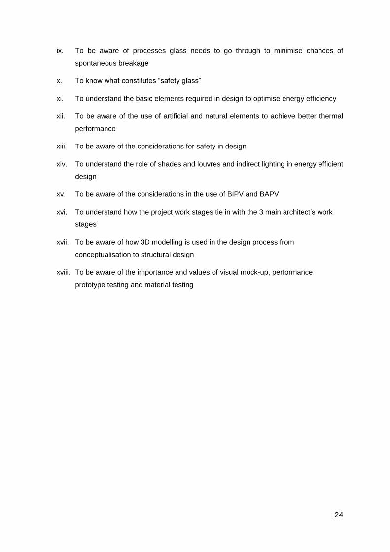
ix. To be aware of processes glass needs to go through to minimise chances of
spontaneous breakage
x. To know what constitutes “safety glass”
xi. To understand the basic elements required in design to optimise energy efficiency
xii. To be aware of the use of artificial and natural elements to achieve better thermal
performance
xiii. To be aware of the considerations for safety in design
xiv. To understand the role of shades and louvres and indirect lighting in energy efficient
design
xv. To be aware of the considerations in the use of BIPV and BAPV
xvi. To understand how the project work stages tie in with the 3 main architect’s work
stages
xvii. To be aware of how 3D modelling is used in the design process from
conceptualisation to structural design
xviii. To be aware of the importance and values of visual mock-up, performance
prototype testing and material testing

25
Chapter 3: Curtain Wall Systems
3.1 Modern Architecture Precedents
Curtain walls are commonly described as an external building wall which carries no roof or
floor loads and comprises primarily of metal, or a combination of metal, glass and other
surfacing materials like granite or any other stones supported by a metal framework.
3.2 Two Basic Types Of Curtain Wall Systems
3.2.1 Custom Design
Walls designed specifically for one project, using parts and details specially made for this
purpose.
3.2.2 Standard Design
Walls made up principally of parts and details standardised by their manufacturer and
assembled in accord with either the architect's design or the manufacturer's stock patterns.
3.3 The 3 Main Façade Systems Are:
3.3.1 Stick System (Figure 23)
3.3.2 Semi-Unitised System (Figure 24)
3.3.3 Unitised System (Figure 25)
Figure 23 Stick System Figure 24 Semi-Unitised System Figure 25 Unitised System
(Courtesy: AgFacadesign & G FACADESIGN Pte Ltd (Fig 23 & 24) and Pixabay.com(Fig 25))
One of the most commonly used terms for façade systems is “curtain wall”.
3.4 Why Is It Called: “Curtain Walls”?
The term “curtain walls” refers to the “unitised system” as the key characteristic of it is that the
system resembles how curtains are installed. Their behaviour after installation enables it to

26
move “freely from its hung (installed) position”. Hence, it is often referred to as “unitised curtain
wall system”.
Figures 26 And 27 Unitised System Used On High Rise Buildings
(Courtesy: Wikimedia - Hawyih (Fig 26) and Pixabay.com (Fig 27))
3.5 Must Curtain Walls Be Used in High-Rise Buildings?
Images from around the world continuously show “glass towers” in almost every major city
(Figures 26 and 27). This is because unitised curtain wall systems today have been so well
developed and refined to a level that it meets the high performance requirements needed for
tall buildings including “super high rise towers”. It has become a standard practice that
prefabricated unitised curtain walls are used whenever a high-rise building is built.
However, low-rise buildings although not subjected to the extreme high wind loads, can also
use unitised curtain wall systems. The main reasons for low-rise buildings using unitised
curtain wall systems include:
a. Quality of finishes,
b. Speed of erection
c. High performance value
d. Aesthetics value

27
Chapter 4: Façade Design Requirements: Main Design Drivers For Unitised Curtain
Walls
4.1 Unitised Curtain Wall
4.1.1 Characteristics:
a. Prefabricated in controlled environment, glazed panels mounted directly onto slab
edges (Figures 28 and 29).
b. Full height mullions and transoms erected into position between slab edges.
c. The system spans between floors of heights up to 6 metres or maximum length of
extruded mullions.
d. Vertical movements between floors are accommodated in stack joints of mullions
located typically at slab/floor finish level.
e. Glass glazed into mullion/transom frames provide the air/water seals.
f. Structural sealant and/or clips and fixings where mechanical fixings are required
by codes secure the glass panel.
4.1.2 System Requirements:
a. Holes in mullions (concealed within horizontal transom) provide the pressure
equalization (Figures 30 and 31)
b. Extruded “male and female” mullion configuration provides the movement
capability under creep.
c. Stack joint allows for anticipated movements particularly those associated with the
dead load loading.
d. Extruded gaskets within provide the air, water and acoustic seals while allowing
for predicted movements
e. One key brackets from mullion fixed directly to structure to take the dead load of
the façade panel itself

28
Figures 28 And 29 Unitised System Under Erection And Completion (Courtesy: Fosters + Partners Pte Ltd (Fig 28)
and Pixabay.com (Fig 29))
Figure 30 Typical Mullion Figure 31Typical Stack-Joint
(Courtesy: Arup Singapore Pte Ltd)
4.2 Semi Unitised System
4.2.1 Characteristics:
a. Prefabricated, glazed panels mounted on a site installed sub frame (Figures 32 and 33).
b. Sub frame consists of mullions, and perhaps transoms erected into position between
slab edges.
c. The system spans between floors of heights between 5.5 metres to 12.5 metres
d. Vertical movements between floors are accommodated in sliding splice joints of mullions.
e. Glass is glazed into cassette frames that form air seals against the sub frame.
f. Cassettes are secured to the sub frame by means of clips and fixing
4.2.2 System Requirements:
a. Cavities between cassette elements that are pressure equalised as set out
b. Mullion joints are fully spliced and sealed. Seals shall allow for predicted movements
c. Cassette frames designed with sufficient strength and rigidity consistent with rear air
seals and restraint positions
d. Metal brackets connected onto the mullions are then fixed onto metal frame structure
Holes in Mullion

29
Figures 32 Semi-Unitised System Completion Figures 33 Semi-Unitised System Detail
(Courtesy: Wikimedia - Socksiong (Fig 32) and Arup Singapore (Fig 33))
4.3 Stick System
4.3.1 Characteristics:
a. Mullions and transoms erected into position between slab or parapet edges complete
with gaskets where detailed (Figures 34 and 35)
b. Gaskets and small joint sealant between mullions and transoms as required
c. Vertical movements between floors are accommodated in sliding splice joints of mullions
d. Glass is frameless glazed on-site, with minimum use of wet seals
4.3.2 System Requirements:
a. Machined mullions and transoms delivered to site
b. Brackets to main structure supporting mullions
c. Mullion joints are fully spliced and sealed. Seals shall allow for predicted movements
d. Allowance for tolerance and thermal expansion at transom – mullion connections
e. Glazing support and back-pans with jointing consistent with the predicted movements,
particularly those associated with the mullion splice
f. Covers and clips with jointing consistent with predicted movements
Figure 34 Stick System Under Installation Figure 35 Installation Require External Access
(Courtesy: AgFacadesign & G FACADESIGN Pte Ltd (Fig 34) and Arup Singapore Pte Ltd (Fig 35))

30
Chapter 5: Curtain Wall: Key Points – Fabrication And Assembly / Structural Comparison / Weather Proofing
In summary, the major differences between the 3 “basic” façade systems are tabulated in table below.
Table 1: Comparison Of 3 Main Façade Systems
Unitised System Semi Unitised Stick System
Design Comprises aluminum
extrusions
Mullions: Vertical split “male
and female” profiles
interlocked for side (“Left-
Right”) movements
Stack joint: Horizontal split
“male and female” profiles
for vertical (“up-down”)
movements
Transom: Horizontal “box”
profile at waist level (as
barrier) or close to ceiling
Comprises extruded
sections specifically
designed for each
installation
“Gutter” profile forms the
base with secondary profiles
to capture and secure the
“cassette” where it is
structurally bonded onto the
glass
Dead load supports and
toggle to provide support
and secure the glass
Window units made to be
inserted into “openings”.
Lugs used for adjustments
of frames
Control to achieve
consistent “designed joints”
widths difficult to achieve
High level of quality checks
required especially for
setting out
Panels alignment between
different levels/floors not
achievable as panels are
31
level to form the spandrel
panel
Panels alignment between
different levels/floors
achievable
Panels alignment between
different levels/floors
achievable
installed on a floor by floor
basis
Fabrication Glazed panels are
fabricated and completed in
factory ready for installation
when delivered to site
Glazed panel with aluminum
“cassette” structurally
bonded
Glazed panels are often
“site glazed” into the frame
with beading to hold the
glass into position
Installation Installed straight onto (RC)
slab edge through a single
fixing angle bracket to
provide the “in/out”
tolerance during installation
Extruded channels secured
onto steel frame structure
with extruded clips and
toggle designed to receive
the glass panel where the
“cassette” had been
structurally bonded
Glazing frames temporarily
propped and plumbed on-
site within the “opening”
prepared. Precise
accuracies are often difficult
to achieve due to the
different trades and
materials involved
Pressure
equalization
Neatly concealed within the
mullion and transom
intersection
Achieved through the
different extruded frames
Not achievable

32
Sun shading Easily accommodated with a
metal bracket-plate
mounted to mullion
extrusions
Difficult to integrate into the
glazed system
Unable to incorporate into
the window system.

33
Chapter 6: Components Of Curtain Wall Façades – Glass, Aluminium Extrusion And
Sealants
The main components used in a typical façade comprises the following:
6.1 Glass
a. Glass is a non-crystalline amorphous solid that is often transparent and has
widespread practical, technological, and decorative usage in, for example, window
panes, tableware, etc.
b. The most familiar, and historically the oldest types of glass are based on the
chemical compound silica (silicon dioxide), the primary constituent of sand.
c. Many applications of silicate glasses are derived from their optical transparency.
This gives rise to one of silicate glasses' primary use as window panes. Glass will
transmit, reflect and refract light. Glass can be coloured by adding metallic salts,
and can also be painted.
d. For building façades, glass used are typically as follows;
i. Single or monolithic glass
ii. Laminated glass - where 2 sheets are adhered together using Poly Vinyl Butryl
(PVB), a form of inter layer that bonds the glass sheets together
iii. Double glazing - where an air gap for thermal reasons, separates the sheet
glass which is often mounted onto a frame.
Building envelope glass may also be processed to achieve a more superior quality in
performance. Some of the common glasses used in buildings are;
a. Annealed glass - non heat treated glass
b. Heat strengthened glass - heat treated
c. Tempered (or toughened) glass - heat treated
Other types of glass treated to produce a different quality of glass include:
a. Low Emissivity (Low E) glass - a coating on glass to improve its thermal properties
b. Low iron glass - a reduction in iron content to provide “clearer” glass visibility
c. Non-slip glass - a coating applied onto the glass to achieve anti-slip properties
d. Laminated glass - to achieve some “safety” quality by “bonding” the glass together
and prevent shards from “flying” in the event of breakage. The laminate will also
add acoustic value to the glass. Coloured laminate may be used to achieve
different tones and/or “patterns” inherent within the laminate. Overhead glass like
canopies will require lamination to prevent glass falling in event of breakage
(Figure 36).

34
e. Fritted glass - a paint coating “baked” onto glass to provide additional shading
value.
Figure 36 Canopy Laminated Glass With Frit Coating. (Courtesy: AgFacadesign & G FACADESIGN Pte Ltd).
6.2 Aluminum Extrusion
Aluminum extrusion is a technique used to transform aluminum alloy into objects with a
definitive cross-sectional profile for a wide range of uses (Figures 37 and 38). Building façades
use the extrusion process to make the most of aluminum’s unique combination of physical
characteristics. Its malleability allows it to be easily machined and cast. As aluminum is one
third the density and stiffness of steel, the resulting products offer strength and stability,
particularly when alloyed with other metals.
6.2.1 The Process Of Aluminum Extrusion
The process of aluminum extrusion consists of the following steps:
a. After designing and creating the shape of the die, a cylindrical billet of aluminum
alloy is heated to 427 oC - 496 oC (800°F-925°F).
b. The aluminum billet is then transferred to a loader, where a lubricant is added to
prevent it from sticking to the extrusion machine, the ram or the handle.
c. Substantial pressure is applied to a dummy block using a ram, which pushes the
aluminum billet into the container, forcing it through the die.
d. To avoid the formation of oxides, nitrogen in liquid or gaseous form is introduced
and allowed to flow through the sections of the die. This creates an inert
atmosphere and increases the life of the die.
e. The extruded part passes onto a run-out table as an elongated piece that is now
the same shape as the die opening. It is then pulled to the cooling table where

35
fans cool the newly created aluminum extrusion.
f. When the cooling is completed, the extruded aluminum is moved to a stretcher,
for straightening and work hardening.
g. The hardened extrusions are brought to the saw table and cut to the required
lengths.
h. The final step is to treat the extrusions with heat in age ovens, which hardens the
aluminum by speeding the aging process.
6.2.2 The Common Finishes In Aluminum
a. Natural anodized
b. Polyester Powder Coating
c. Fluorocarbon or PVF2 Finish
Figure 37 Extruded Aluminium Glazing Frame Figure 38 Extruded Structural Aluminium Bracket
(Courtesy: AgFacadesign & G Facadesign Pte Ltd)
6.3 Gasket And Sealant
A gasket is a mechanical seal which fills the space between two or more mating surfaces,
generally to prevent leakage from or into the joined objects while under compression.
In building façades, extruded gaskets are used to separate the aluminum from being in contact
with each other and causing friction and “cracking” sounds. The gasket will also provide
addition “seals” against water and noise (Figure 39).
In general, gaskets allow for "less-than-perfect" mating surfaces on machined parts where
they can fill irregularities.
It is usually desirable that the gasket be made from a material that is to some degree yielding
such that it is able to deform and tightly fill the space it is designed for, including any slight
irregularities. A few gaskets require an application of sealant directly to the gasket surface to
function properly.

36
Figure 39 Extruded Gaskets (Courtesy: AgFacadesign & G Facadesign Pte Ltd)
Sealant is a substance used to block the passage of fluids through the surface or joints or
openings in materials (Figure 40).
In building construction sealant is sometimes synonymous with caulking and also serves the
purposes of blocking dust, sound and heat transmission. Sealants may be strong or weak,
flexible or rigid, permanent or temporary. Sealants are not adhesives but some have adhesive
qualities and are called adhesive-sealants or structural sealants (Figure 41). Others are used
primarily as “weather seals”.
Figure 40 Weather Sealant Figure 41 Structural Sealant
(Courtesy: AgFacadesign & G Facadesign Pte Ltd )

37
Chapter 7: Façade Systems: Specialist Design – Monocoque /”Hybrid” Custom Design
However, through the advent of information technology, 3D modelling software and the desire
of designers to provide “creative designs”, façade systems beyond the 3 main categories listed
above have inevitably evolved to capture the imagination and desires of designers and owners
alike.
For ease of reference, we shall call this “specialist designed system”. These systems look very
different from the 3 basic façade systems mentioned above. However, all systems will have to
incorporate the fundamental performance requirements needed for a “curtain wall”.
7.1 Monocoque Facade
An easy point of reference is to compare this to a seashell. In a seashell, the “skin” and the
“structure” are fused into a homogeneous element making it impossible to separate them apart
(Figures 42, 43 and 44).
In building façades, glass cladding is the “skin” and the support members are the “structure”.
Attempts to mimic the seashell have resulted in a monocoque façade system where the glass
and frames “act as one”. However, in construction terms this is not possible as glass cracks
when subjected to forces when in contact with harder materials like metal.
Although the “skin” of a seashell contributes to direct load transfer, in a monocoque façade
system, the glass is not subjected to any in-plane stress and are allowed to move “freely” but
contained within its own module.
Figures 42, 43 And 44 Monocoque Structures Used On Different Sites And Support Systems
(Courtesy: Pixabay.com)

38
7.2 Hybrid Facades
7.2.1 Glass Fins Facade
Glass fins are integrated into aluminium panels to provide additional thermal insulation value
to a distinctive façade (Figures 45, 46 and 47). Glass fins are “sandwiched” between the
insulated aluminium panels, which provide a thermally efficient barrier to screen off the sun
and harmful UV radiation into the building.
Figures 45, 46 And 47 Glass Fins With Aluminum Insulated Panels
(Courtesy: Arup Singapore Pte Ltd (Fig 45) and AgFacadesign & G Facadesign Pte Ltd (Fig 46 & 47))
7.2.2 Infinity Pool Integrated Facade
Infinity pool glass panels are integrated within the façade modules (Figures 48 and 49). The
“spandrel” panels between the double volume glazing aligned with the pool glass form a
continuous “band” around the façades.
Figures 48 Completed Building Figure 49 Façade With Infinity pool
(Courtesy: AgFacadesign & G Facadesign Pte Ltd)

39
7.2.3 Layered-Glass Facade
A naturally ventilated façade using glass panels that are staggered in both horizontal and
vertical directions (Figures 50 and 51). Supported off a central mullion, glass panels are
supported using “clips” at the outer edges. The module of these can be adjusted to suit both
horizontal and/or vertical directional requirements.
Figure 50 And 51 Layered Glass Façade Allows Air And Drizzles In For The Plants
(Courtesy: AgFacadesign & G Facadesign Pte Ltd)
Although very different in appearance, all façade systems are subjected to the same criteria
and must strictly comply with them. The main difference will be the different loads each façade
will be subjected to. This will vary with site and building performance requirements which are
set by the structural engineer before commencement of the design process.
For thermal performance, sun screens may be integrated depending on the system(s) selected
and design requirement(s).
7.3 Design Process – Key Principles
The above examples show that façades can be developed to meet any design required. The
key is to understand the following;
a. Materials - the limits and capabilities of different materials
b. Technology - how materials can be transformed into a much stronger form
c. Information Technogy - the capabilities of different softwares and programmes that
can assist in simulation prior to fabrication

40
Chapter 8: Frameless Structural Glass Walls – “Spider” Clamps On Glass Fins, Steel
Frame Or Cable-Net systems, Patch-Plate And Clamp-Plate
8.1 Frameless Structural Glass Walls
Another façade type is known as “frameless glass” system.
Glass panels for these are not contained within any edge frame to act as supports. The glass
panels are held in place either by “point-fix” (“spider”) rotules or “clamp-plate”.
There are 2 basic systems available:
8.1.1 Point Fixed Glass
Require the glass panels to have holes at the 4 corners and additional holes at mid span of
glass for longer span glass (Figure 52).
Stainless steel rotules and threaded bolt with the required separators connect the glass back
to the spider-arms which are fixed onto the system.
Figure 52 Point-Fix Stainless Steel Cast Supports (Courtesy: AgFacadesign & G Facadesign Pte Ltd)
8.1.2 Clamp-Plate glass
Does not require any pre-drilled holes in the glass.
The glass panel sits on the “ledge” typically close to either end of the glass panel and relies
on plates on either side of the glass to keep it in position and not falling out (Figures 53 and
54).

41
Figures 53 And 54 Clamp-Plate Fittings In Different Profiles
(Courtesy: AgFacadesign & G Facadesign Pte Ltd)
For better thermal performance, double glazed units with low-E coatings may be used.
Frameless glass walls are often used as “high screen glass” around “podium” levels and
comprises mainly of “fixed” glass panels i.e. no window openable units.
It is also difficult to incorporate other elements like sun-shades, louvres, etc.
8.2 Four Categories Of Frameless Glass Walls
8.2.1 Glass Fin System
Laminated glass fins provide the structural support for the face glass panels.
Due to glass transparency, glass fin system is visually less obstructive and is often used where
“visual transparency” is of high importance (Figures 55 and 56).
Care is needed in the design to ensure that the face glass will not collapse progressively
should the supporting glass fins break.
Typical examples where glass fin frameless glass walls are commonly used include car
showrooms, VIP viewing boxes, exhibition areas, etc
Glass fin system may be either:
a. Full height – from floor to ceiling; or
b. Cantilevered from the top – allows wider usage of space beneath

42
Steel Post
Figures 55 And 56 Glass Fins Allows Transparent Views In And Out Of The Building
(Courtesy: Patricia Collera (Fig 55) and Foster + Partners Pte Ltd – Nigel Young (Fig 56))
8.2.2 Steel Frame Or Steel Post
Steel member provides the structural support for the face glass. This is one of the simpler
systems. The size of the steel section is determined by the total span required and can use
standard off the shelf profiles (Figure 57).
The bigger the cross section, the more obstructive it is visually.
The steel frame system can be used for any building type as long as “transparent vision” is
not a priority.
Steel Frame or Steel Post are available in standard profiles like;
a. Circular or rectangular sections
b. “I” or “H” profiles
c. Built-up sections to suit
Figure 57 Steel Post With Point-Fix Glass System (Courtesy: AgFacadesign & G FACADESIGN Pte Ltd)

43
8.2.3 Truss System
A truss system allows a large area of glass wall to be achieved.
Depending on the system, trusses can be formed using standard sections or machined rods
and cables to provide an intricate network assembly (Figures 58 to 61)
Engineering of cable truss system will be more elaborate and the structure will also need to
be analysed together to determine the forces.
Different truss systems are:
a. Bow truss
b. Cable truss
c. Standard truss
Figure 58 Bow Truss System Figure 59 Truss System Figure 60 Cable Truss Figure 61 Hanging Truss
(Courtesy: AgFacadesign & G FACADESIGN Pte Ltd (Fig 58-60) and Arup Singapore Pte Ltd (Fig 61))
8.2.4 Cable-Net System
Often referred to as the “racket system”, cable net systems resemble how the guts are strung
in rackets to provide the necessary tension to counter the forces acting on it, just like when a
ball at high speed bounces off the surface of the tensioned guts of the racket (Figures 62 and
63).
Technically, this system, like the cable truss needs to be engineered with the supporting
structure to ensure that the tensile forces of the cable-net (or “guts”) on the perimeter frame
are able to withstand the forces acting on the perimeter frame. It can have very large spans
horizontally (i.e. as a “roof element”) or vertically as a “wall”. For added safety measure,
additional layer of cables may be integrated behind the cable-net supporting the glass wall to
provide an added “security feature” against flying laminated glass in the event of a bomb blast.
Aesthetically, it is probably the least visible (from afar) as the tensioned cables tend to be
relatively small in diameter and “disappear” from view.
Truss System

44
Figures 62 And 63: Cable-Net System (Detail And General View)
(Courtesy: AgFacadesign & G FACADESIGN Pte Ltd (Fig 62) and W&W Glass, LLC (Fig 63))
Although glass is brittle in tension, it can be extremely strong in compression when
appropriately used. It is up to the designer’s understanding of how glass (or materials) is used
and develop a detail that allows the glass (or other materials) to be applied “innovatively” such
that it will perform at its optimum state to achieve maximum efficiency.
8.3 Examples Of Structural Glazing
8.3.1 “Glass Connector”
A “glass connector” is a covered link to the new wing at the Singapore National Museum
(Figures 64 and 65). It consists of an all glass structure that uses laminated glass as wall
panels, fin stabilizers and roof panels. All the laminated glass are connected using high
strength stainless steel plates. The glass connector which measures 6m(W)x5m(H)x25m(L)
is supported on a steel frame structure embedded within the century old brickwalls.
Figures 64 And 65: Glass Used In More Structural Applications As Vertical Supports And As Fin Stabilizers
(Courtesy: AgFacadesign & G FACADESIGN Pte Ltd)

45
8.3.2 Glass Bottom And Glass-End Pool (Unbuilt)
Figures 66 and 67 show an all glass end and glass bottom pool. It consists of the laminated
glass with embedded steel plates which are connected using point-fix connections.
Figures 66 And 67: Glass End / Bottom Pool With Embedded Steel Plates Connected Using Point-Fix Connections
(Courtesy: Arup Singapore Pte Ltd)
8.3.3 Glass Tubes
Figure 68 shows “glass tubes” as structural compression members to resist wind loads on a
cable-net façade.
Glass tubes are tensioned via a steel rod at both ends of special castings. They are fixed onto
a cable net system and the glass tubes act as compression struts transferring the live wind
loads from the all glass façade onto the steel columns.
Figure 68 Glass Tubes As Compression Struts (Courtesy: Foster + Partners Pte Ltd)

46
Chapter 9: Glass Processing And Criteria
9.1 How Is Glass Made?
Almost all glass produced today in developed countries is done by the “float process”.
The glass composition materials, mainly silica sand, soda ash and limestone, are melted in a
furnace and then flowed onto a bath of molten tin. The glass is formed and gradually cools as
it moves from the tin bath to an annealing lehr, which is a controlled cooling chamber. As it
moves through this process, the glass is in the form of a continuous ribbon, which is cut to
size and packaged at the final stage.
9.2 Glass Processing
Ever since glass was first produced, the use of it has been widespread and the demand for
use of glass on interiors and/or exteriors will keep increasing.
In building envelopes, glass forms the most area of any curtain wall façade.
Through advancement in technology, glass treatment has developed over the years to meet
different building requirements.
Below are two different types of glass performance requirements that are mostly considered
for buildings;
a. Thermal - through the use of coating technology
b. Structural - from heat treatment process on the glass
9.3 Thermal Performance Glass
High energy consumption is the main concern for commercial buildings as bills chalk up in
terms of air-conditioning and lighting costs.
Low Emissivity (Low E) glass provides the solution to achieve both interior comfort and energy
cost savings. It avoids unwanted heating of interiors while still allowing as much daylight into
the building as possible.
The Low E coat provides maximum solar control with astonishing light transmittance and a
low external reflection. There is also considerable freedom when designing the façade as Low
E glass is available in various thickness and sizes.

47
Besides double glazing units (DGU), Low-E coating on glass has developed significantly to
meet certain performance standards.
Originally started off in the cold climates, it is now commonly used in the tropical heat
environment.
The 2 main factors concerning thermal requirements are;
a. U-value
b. Shading Coefficient (SC) value
Low E coated solar control glass, comes in various colours, solar control and light
transmittance. A Low E coating applied via chemical vapour deposition is commonly referred
to as a “hard coat”, whilst a Low E coating applied via magnetron sputtering is known as a
“soft coat”.
Soft coat Low E Glass performs better at thermal insulation, but is prone to oxidation upon
exposure to the atmosphere. Hence, soft coat Low E Glass needs to be double-glazed or
laminated with edge deletion.
“Triple coat Silver Low E” is also available for an ideal balance of solar control and high visibility
for all-year round comfort, making it perfect for façades, windows and building envelopes.
9.4 Structural Performance Glass
9.4.1 Glass Processing And Glass Traceability
Glass is made up of different raw materials such as sand, soda, lime, silica, etc..
The material will be cleaned and have to go through certain processes to ensure that the “right”
quality is achieved before the production of float glass.
“Impurities” inherent in various raw materials will determine the quality of the raw glass. These
are impossible to totally remove.
However, “impurities” in float glass can be detected by laser scanners while still on the
production line. (Figures 69 and 70).

48
Figures 69 And 70: Glass On Roller Bed Production Line Being Scanned For Impurities
(Courtesy: AgFacadesign & G Facadesign Pte Ltd)
Impurities are traced and “marked” onto the glass (Figures 71 and 72) using a computer
system. Depending on the proximity of the impurities, the glass will be cut and directed to
different “groups” of glass production from low to high presence of impurities.
Glass with the least or low presence of “impurities” will be treated as high quality production
glass and will command a higher premium.
Figures 71 And 72: Glass Impurities Check Scanning By Computer And Distributed To Different Areas For Sorting.
(Courtesy: AgFacadesign & G Facadesign Pte Ltd)
9.4.2 Heat And Quenching Process
Heat treatment is the main process that glass needs to go through in order to transform it from
a normal (annealed) glass to either heat-strengthened or tempered glass.
Glass sheets flow into a heat oven to be heated up and subsequently go through quenching
(by air).
The heated top and bottom surfaces of the glass sheet will be in a state of “tension” and when
it goes through the sudden cool air quenching process (Figures 73, 74 and 75), the surfaces
retract and go into compression .
It is through this transformation process that “surface compression” on the glass surfaces is
obtained.
Two factors that determine whether the glass will be transformed into “heat strengthened” or
“tempered” glass within the heat oven are:

49
a. Temperature
b. Speed of roller bed
Figures 73 And 74: Heat Oven And Quenching Compartment Of Tempering Line
(Courtesy: AgFacadesign & G Facadesign Pte Ltd)
Figure 75: Close Up View Of Roller Bed And Air Nozzles At Quenching Compartment
(Courtesy: AgFacadesign & G Facadesign Pte Ltd)
Heat treated glass has “surface hardness” comparable to untreated “annealed” glass. It’s the
surface compressive forces that give it the “impact resistance” so that it can withstand impact
unless the impact exceeds the compressive forces of the glass. When this happens, the
pattern of glass breakage will reveal if the glass has been “heat strenghtened” or “tempered”.
In general the surface hardness of “tempered” glass is about twice that of “heat strengthened”
glass.
At the end of the tempering line, the glass will be given a visual check on the “flatness” of the
heat processed glass. The glass will be viewed against a “zebra board” (Figures. 76 and 77)
where the reflections will show if the “roller waves” on the glass have visually exceeded the
limits.
Figures 76 And 77: “Zebra Board” Lines Reflected For Visual Check On The Processed Glass Flatness At End Of
Tempering Process (Courtesy: AgFacadesign & G Facadesign Pte Ltd)

50
When glass breaks “spontaneously” or “on its own”, it usually occurs in “tempered glass”
because surface compression in tempered glass is almost 4 times that of annealed glass.
One of the most common causes is often due to nickel sulphide (NiS) impurities embedded
within the glass which has expanded beyond the surface compressive forces of the tempered
glass.
9.4.3 Heat Soak Test
NiS can be detected through the “heat soak” process.
The objective of this test is to allow any impurities embedded within the tempered glass to
expand so that they penetrate through the surface of the tempered glass. This allows the glass
panel to shatter “safely” within the heat soak oven (Figure 78).
Figure 78: “A”- Frame On Roller Track Where Glass Sheets Are Placed During Heat Soak Process Inside The
Heat Soak Oven (Courtesy: AgFacadesign & G Facadesign Pte Ltd)
Heat soak process standards are found in different codes but in general the process involves
the following steps within the heat soak oven;
- Temperature raised to 290oC (+/- 5oC)
- Temperature of 290oC and holding time of 2-4 hours
- Temperature drops to room temperature before heat soak oven is opened
The total duration ranges between 4 to 6 hours depending on the code requirements and/or
the heat soak oven capabilities.
9.5 Laminating Glass
Glass technology has progressed and laminating glass using poly vinyl butryal or “PVB”
provides added “structural” strength and additional “safety”.
Laminating glass is manufactured in a cleanroom. This is to ensure that there is no dirt or
particles trapped between the glass before the lamination process (Figures 79 - 81).

51
Figures 79, 80 And 81: Glass Is Cleaned Before Entering The Cleanroom Where PVB Sheet Is Laid
Figures 82, 83 And 84: Glass Coming Out Of Cleanroom And The Heat Machine And Lifted Off
Figure 85 Autoclave Oven
(Courtesy: AgFacadesign & G Facadesign Pte Ltd)
The final step in the glass lamination process is in the autoclave oven (Figure 85) where the
opacity of the pvb and traces of bubbles trapped between the sheets of glass are cleared
through heat pressure resulting in the “transparency” of the “clear” laminated glass that we
see.

52
Chapter 10: Design Consideration and Safety in Design
10.1 “Safety Glass”
In Singapore, for single ply applications only “tempered glass” is considered as “safety glass”.
This is due to the break pattern in tempered glass which breaks into small granules (Figure
88) as opposed to “shards” like break patterns (Figure 86) in annealed and heat strengthened
glass (Figure 87).
Other types of “safety” glass are laminated glass (Figure 89) and bullet-proof glass (Figure
90).
10.2 Glass Break Patterns
Figure 86: Annealed Glass (Courtesy: Pixabay.com)
Figure 87: Heat Strengthened Glass (Courtesy: AgFacadesign & G Facadesign Pte Ltd)
Figure 88: Tempered Glass (Courtesy: Pixabay.com)

53
Figure 89: Laminated Glass (Courtesy: Pixabay.com)
Figure 90: Bullet-Proof Glass (Courtesy: Saudi American Glass Company Pte Ltd)
10.3 What Is Safety Glazing?
Glass is a breakable material, which breaks into smaller sharp pieces called shards. Shards
can cause serious injury. Safety glazing material, usually tempered glass or laminated glass,
reduces the risk of injury. This is accomplished in the case of tempered glass by the
characteristic break pattern of breaking into many small pieces. In the case of laminated glass,
it is the adhesion of the glass pieces to the inner plastic layer.
In Singapore, laminated glass with the pvb will keep the broken glass “in place” during
breakage and prevent glass from “flying off”. This is seen as a “safety feature” and hence
laminated glass is considered as “safety glass”
10.4 What Is Security Glazing?
Security glazing products usually involve multiple layers of glass, and in some cases acrylics
which are usually laminated. This achieves maximum impact resistance from explosions,
ballistic assaults and even simple forced entry. There is a wide range of such specialty glass
products.

54
10.5 Fabrication And Design Limitations
As mentioned earlier, with the understanding of materials, technology and aid from computer
software, there are literally “no limits” to the façade designs that can be achieved.
However, to achieve efficient and economical solutions, the designer must also be aware of
what the industry “standard” capabilities and practices can achieve.
For building envelope or façade design, the key material is glass and it forms a large portion
of the overall costs.
It is vital that glass sizes are designed optimally so that the production, fabrication, installation
and replacement can be done with ease.
10.6 Glass Processing Lines
For glass production, the following processes and machines limit maximum glass sizes;
a. Low-E coating line
b. Tempering machine
c. Lamination plant
Glass sheet sizes - Glass comes in standard “stock sizes” including “Jumbo size” glass. Where
possible it will be beneficial if glass modulation can be optimised to minimise wastage.
Glass thickness - Standard glass thickness commonly used in building façades range from
6mm, 8mm, 10mm, 12mm, 15mm, 20mm. Each increment has added strength as well as
costs. The design should therefore consider these carefully to avoid using thicker glass than
necessary.
Glass fixings - Depending on the system used, how the glass is fixed will have a significant
impact on the type of glass and thickness required. Fixings as described above ranges from
“frameless point-fixed, clamp-plates, structurally glazed to fully embedded glass.
Glass shapes - The modulation or shape of the glass will have direct impact on the “deflection
and stress” on the glass. This will have direct impact on the glass thickness to be used.
Glass types - Thermal performance requirements will determine whether the glass needs to
be single or double glazed units (IGU or DGU) or to what extent of Low-E coating the glass
should have. An alternative but less popular nowadays is the use of tinted glass.

55
Glass coatings - Coating technology on glass is constantly improving. The main focus has
been on thermal performance where the important “U” and “SC” values will have direct impact
on thermal requirements and calculations.
Coatings such as “non-slip” and “anti-reflective” are also commonly produced.
“Clear glass” - Iron content in glass contributes to the “green edge” of glass. However low iron
glass reduces this “green edge” and provides a “clearer” glass often used in locations where
“clarity” of the objects are important, like jewellery cases where the “natural colour” of the
display can be easily seen.
Curved glass - including “double curve” and as well as “free form” glass is also getting used
quite often. Production of these is not cheap and not many plants have such machines and
capabilities. Quality control will be essential especially where laminated curved glass is
required; the alignment of glass sheets will be vital to prevent chipping and cracking.
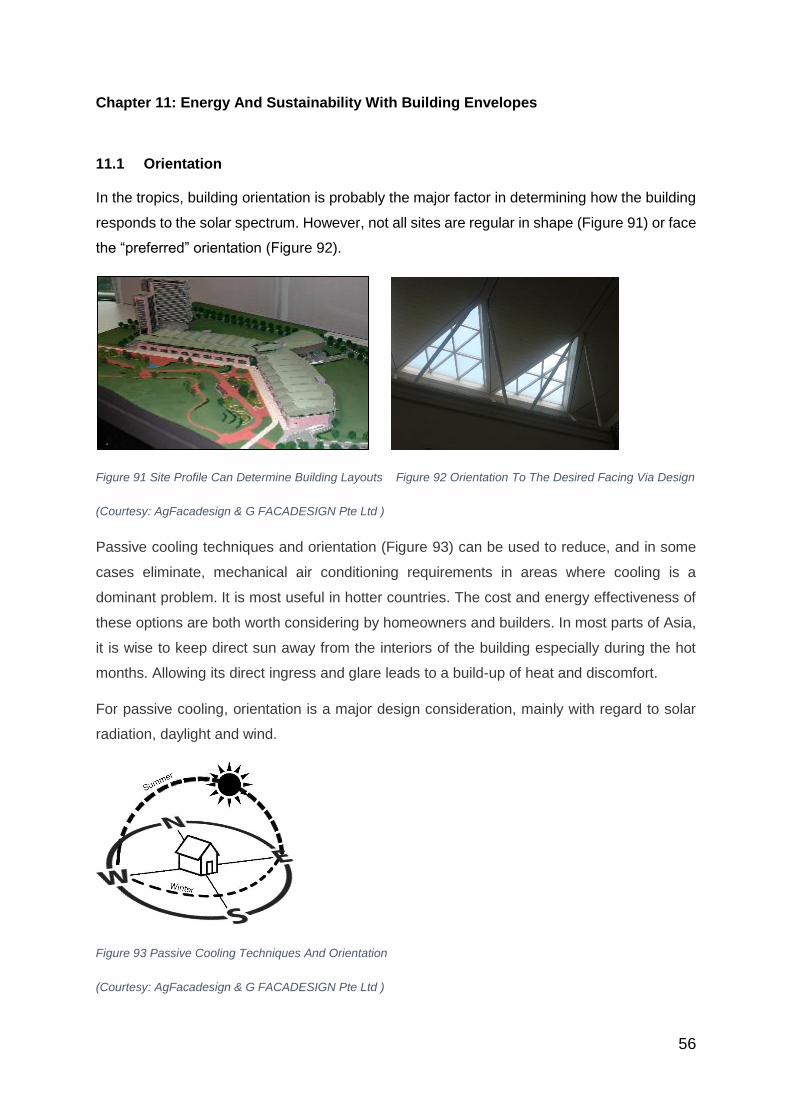
56
Chapter 11: Energy And Sustainability With Building Envelopes
11.1 Orientation
In the tropics, building orientation is probably the major factor in determining how the building
responds to the solar spectrum. However, not all sites are regular in shape (Figure 91) or face
the “preferred” orientation (Figure 92).
Figure 91 Site Profile Can Determine Building Layouts Figure 92 Orientation To The Desired Facing Via Design
(Courtesy: AgFacadesign & G FACADESIGN Pte Ltd )
Passive cooling techniques and orientation (Figure 93) can be used to reduce, and in some
cases eliminate, mechanical air conditioning requirements in areas where cooling is a
dominant problem. It is most useful in hotter countries. The cost and energy effectiveness of
these options are both worth considering by homeowners and builders. In most parts of Asia,
it is wise to keep direct sun away from the interiors of the building especially during the hot
months. Allowing its direct ingress and glare leads to a build-up of heat and discomfort.
For passive cooling, orientation is a major design consideration, mainly with regard to solar
radiation, daylight and wind.
Figure 93 Passive Cooling Techniques And Orientation
(Courtesy: AgFacadesign & G FACADESIGN Pte Ltd )

57
In places with a tropical climate like Singapore, long façades of buildings oriented towards
North—South are preferred as East and West receive maximum solar radiation throughout
the year.
11.2 Insulation
The purpose of insulation is to reduce heat gain and heat loss. Insulating the roof is a good
idea to reduce the heat transfer from the roof. The more insulation in a building exterior
envelope, the less heat is transferred into or out of the building. Materials and easy techniques
are available for insulating jobs (Figure 94). Materials like 40 mm thick expanded polystyrene
insulation (thermo coal) or broken bricks are laid on top of the roof and finished with mortar.
Roof tiles with less thermal conductivity are also available in the market. Painting the roof
white will reduce heat absorption. Air cavities within walls or an attic space in the roof ceiling
combination reduce the solar heat gain factor. Vacuum insulated glass, thermal insulating
glass and heat reflective glass can be used in windows and glazing. These will reduce the
heat transfer from outside to inside the building significantly.
Figure 94 Insulating Building Material (Courtesy: AgFacadesign & G FACADESIGN Pte Ltd )
11.3 Shaded Envelope
Heat gain through a window is much higher as compared to that through an opaque wall.
Incorporation of shading elements with windows help in keeping out the sun‘s heat, block
uncomfortable direct sun, and soften harsh daylight contrasts. Shading devices are therefore
necessary to allow glare-free natural light. External shading is the most effective way of
shading, as it cuts off direct sunlight during summer and allows winter sunlight to enter inside
the space (Figure 95). It is preferable to design movable external shading devices on East and
West façades, so that the shades can be removed after the sun faces opposite orientation.
Minimum or no shading is required on North orientation. On South orientation external shades
should be designed after studying the sun path.

58
.
Figure 95 Trellis As A Form Of Shading (Courtesy: AgFacadesign & G Facadesign Pte Ltd)
Movable louvres can cope well with the sun’s altitude and can also be adjusted as per the
angle of the sun‘s altitude, but can be very costly.
Figure 96 Use Of Sunshade Device (Courtesy: AgFacadesign & G Facadesign Pte Ltd)
Shading walls from direct sun can be one of the simplest and most effective ways of reducing
the heat load on a building (Figure 96). Clever use of shade can dramatically improve the
comfort conditions inside. Shading can be done by sun-proof fabric covers, light colour coated
roof sheets and even by grabbing plants. Shading of roof through design features like pergolas
or solar photovoltaic panels help in reducing the incident direct solar radiation on the roof
surface. This in turn helps to reduce the air temperature of the roof and conduction gains in
the space below.
11.4 Landscape
Landscaping is an important element in altering the micro-climate of a place. Proper
landscaping reduces direct sun from striking and heating up building surfaces (Figure 97). It
is the best way to provide a buffer for heat, sun, traffic noise, and airflow or for diverting airflow
or exchanging heat in a solar-passive design. It prevents reflected light from carrying heat into

59
a building from the ground or other surfaces. Additionally, the shade created by trees, reduces
air temperature of the microclimate around the building through evapo-transpiration. Properly
designed roof gardens help to reduce heat loads in a building.
Figure 97 Use Of Landscaping To Assist In Shading (Courtesy: AgFacadesign & G Facadesign Pte Ltd)
11.5 Ventilation
In humid places like the coastal areas, having air flowing over your skin; evaporating the sweat
and cooling your body achieves comfort conditions (Figure 98). For this, it is advisable to have
large openings in the building’s envelope. However, deep overhangs need to be used to
minimise direct entry of sunlight. In addition, openings can be strategically placed to allow the
heat to escape. In a single-storey house, high-level or clerestory windows allow hot air to
escape and thus generate circulation even when there is very little natural breeze. Another
way to set up a stack effect is to install a wind-driven roof vent. They do not require electricity
to run and spin based on the difference between outside and inside temperatures – the hotter
it is outside, the faster they go.

60
Figure 98 Cross Ventilation Across Living Spaces (Courtesy: AgFacadesign & G Facadesign Pte Ltd)
11.6 Design Considerations
11.6.1 Air-Conditioned Versus Naturally Ventilated Space
Places with tropical climate like Singapore, Malaysia, etc can be non-air conditioned (or
naturally ventilated) due to its temperature all year round.
Figure 99 Areas In The Tropics (Courtesy: Wikipedia – Peel, M.C., Finlayson, B.L., and McMahaon, T.A. (University
of Melbourne))
A tropical climate is a climate typically found within the Tropics (Figure 99), while a few
locations outside the Tropics are considered to have a tropical climate. According to the
Köppen climate classification system it is a non-arid climate in which all twelve months have
mean temperatures of at least 18 °C (64 °F).
However, besides temperature, other factors that need to be considered in the design of
naturally ventilated spaces include:

61
a. Relative humidity
b. Wind conditions
c. Security
d. Weather conditions like haze
e. Smells
Other factors are dependent on the needs and requirements of the owners/users and/or
function of the spaces that include:
a. Image
b. Consistent comfort
c. Merchandise
d. Safety
Naturally ventilated spaces are more sustainable (Figure 101) compared to air-conditioned
spaces (Figure 100) but may not be possible due to different conditions
Figure 100 Air Conditioned Office Spaces Figure 101 Naturally Cross Ventilated Spaces
(Courtesy: Pixabay.com (Fig 100) and Foster + Partners Pte Ltd – Nigel Young (Fig 101))
For high rise buildings, natural ventilation with open windows may not be practical as wind
pressure can be extremely high and unpredictable. Hence, curtain walls are mostly not
openable and cooling of the building is by air conditioning.
In most advanced countries, sustainability and energy design will need to be incorporated to
meet the relevant energy ratings. In Singapore, “There are different “Green Mark” ratings
which are regulated by the Building and Construction Authority (BCA).
Buildings with “glass box” aesthetics will have double glazed units (DGU) for its thermal
properties with Low-E coated glass used to enhance its thermal performance. Due to the high
percentage of glass façade to solid “wall” surface area, the use of Low-E and DGU glass may

62
satisfy the relevant “Green Mark” rating but heat is often felt within the internal spaces. Such
conditions will have a greater psychological impact on the thermal “performance” of the glazed
units.
A louvre (American English) or louvre (British English) is a window blind or shutter with
horizontal slats that are angled to admit light and air, but to keep out rain, direct sunshine, and
noise. The angle of the slats may be adjustable, usually in blinds and windows, or fixed.
An efficient way to achieve effective thermal shading is to use external sun-shades. Louvre
sometimes also known as “Brise soleil” (Figure 102) is an architectural feature of a building
that reduces heat gain within that building by deflecting sunlight.
Figure 102: A Basic Brise Soleil As Shading Device For Vehicles At The Outdoor Carpark Of CENTRAL Mall In
Singapore. (Courtesy: Patricia Collera)
Brise-soleils comprises a variety of permanent sun-shading structures, ranging from the
simple horizontal shades (Figure 103) to elaborate patterned devices (Figure 104)
Figure 103: Bentini S.P.A, Italia Figure 104: Triangulated Screens
(Courtesy: PiuArchitects – Andrea Martiradonna (Fig 103) and Patricia Collera (Fig 104) )
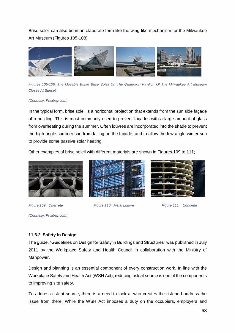
63
Brise soleil can also be in an elaborate form like the wing-like mechanism for the Milwaukee
Art Museum (Figures 105-108)
Figures 105-108: The Movable Burke Brise Soleil On The Quadracci Pavilion Of The Milwaukee Art Museum
Closes At Sunset
(Courtesy: Pixabay.com)
In the typical form, brise soleil is a horizontal projection that extends from the sun side façade
of a building. This is most commonly used to prevent façades with a large amount of glass
from overheating during the summer. Often louvres are incorporated into the shade to prevent
the high-angle summer sun from falling on the façade, and to allow the low-angle winter sun
to provide some passive solar heating.
Other examples of brise soleil with different materials are shown in Figures 109 to 111;
Figure 109 : Concrete Figure 110 : Metal Louvre Figure 111 : Concrete
(Courtesy: Pixabay.com)
11.6.2 Safety In Design
The guide, “Guidelines on Design for Safety in Buildings and Structures” was published in July
2011 by the Workplace Safety and Health Council in collaboration with the Ministry of
Manpower.
Design and planning is an essential component of every construction work. In line with the
Workplace Safety and Health Act (WSH Act), reducing risk at source is one of the components
to improving site safety.
To address risk at source, there is a need to look at who creates the risk and address the
issue from there. While the WSH Act imposes a duty on the occupiers, employers and
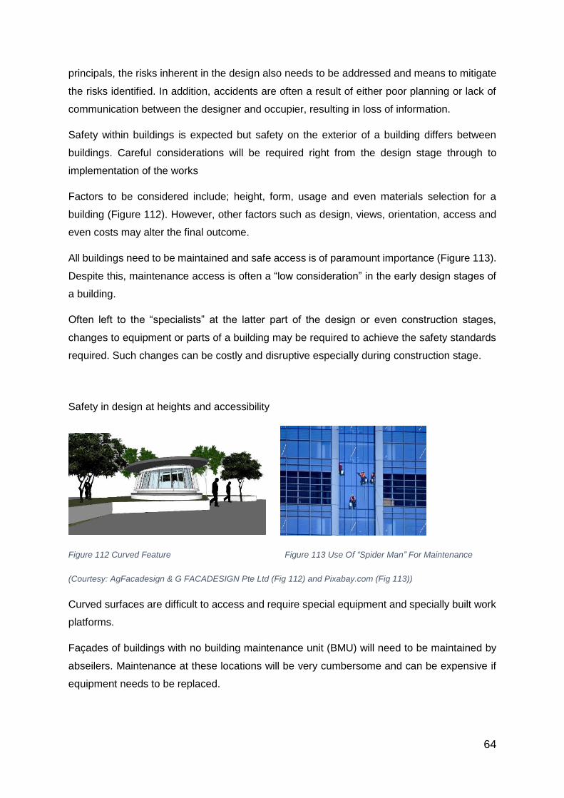
64
principals, the risks inherent in the design also needs to be addressed and means to mitigate
the risks identified. In addition, accidents are often a result of either poor planning or lack of
communication between the designer and occupier, resulting in loss of information.
Safety within buildings is expected but safety on the exterior of a building differs between
buildings. Careful considerations will be required right from the design stage through to
implementation of the works
Factors to be considered include; height, form, usage and even materials selection for a
building (Figure 112). However, other factors such as design, views, orientation, access and
even costs may alter the final outcome.
All buildings need to be maintained and safe access is of paramount importance (Figure 113).
Despite this, maintenance access is often a “low consideration” in the early design stages of
a building.
Often left to the “specialists” at the latter part of the design or even construction stages,
changes to equipment or parts of a building may be required to achieve the safety standards
required. Such changes can be costly and disruptive especially during construction stage.
Safety in design at heights and accessibility
Figure 112 Curved Feature Figure 113 Use Of “Spider Man” For Maintenance
(Courtesy: AgFacadesign & G FACADESIGN Pte Ltd (Fig 112) and Pixabay.com (Fig 113))
Curved surfaces are difficult to access and require special equipment and specially built work
platforms.
Façades of buildings with no building maintenance unit (BMU) will need to be maintained by
abseilers. Maintenance at these locations will be very cumbersome and can be expensive if
equipment needs to be replaced.

65
Chapter 12: Shades And Louvres For Building Envelopes
12.1 Orientation
In the tropical climate, the orientation of a building plays a significant part in the exposure of
solar heat into the building. In Singapore, it is a well-known fact that the late afternoon sun
from the West direction should be avoided as much as possible.
In most cases, sites are usually different in size, shape and orientation. However, in “terraces”,
similar size plots are aligned side-by-side facing the same orientation.
Understanding the site and its surroundings in relation to the sun path movements, angles and
prevailing wind directions will minimise energy consumed by air-conditioners to cool the
building.
Sun-shading elements like brise soleil and other architectural features effectively integrated
into the building design will significantly reduce the energy demand of the building.
In addition, using environmental sustainable design (ESD) software such as ECOTEC, etc will
enable the building to be designed to optimise the environmental conditions for the site.
12.2 Shade And Louvres
Direct sun can generate the same heat as a single bar radiator over each square metre of a
surface, but effective shading can block up to 90% of this heat. By shading a building and its
outdoor spaces we can reduce summer temperatures, improve comfort and save energy.
A variety of shading techniques from fixed or adjustable shades to trees and vegetation can
help depending on the building’s orientation as well as climate and latitude.
In the tropical climate, shades and louvres installed vertically onto building façades (Figures
114 and 115) are very effective as they allow breeze to pass through allowing cross ventilation
and help to deflect rainwater outwards.
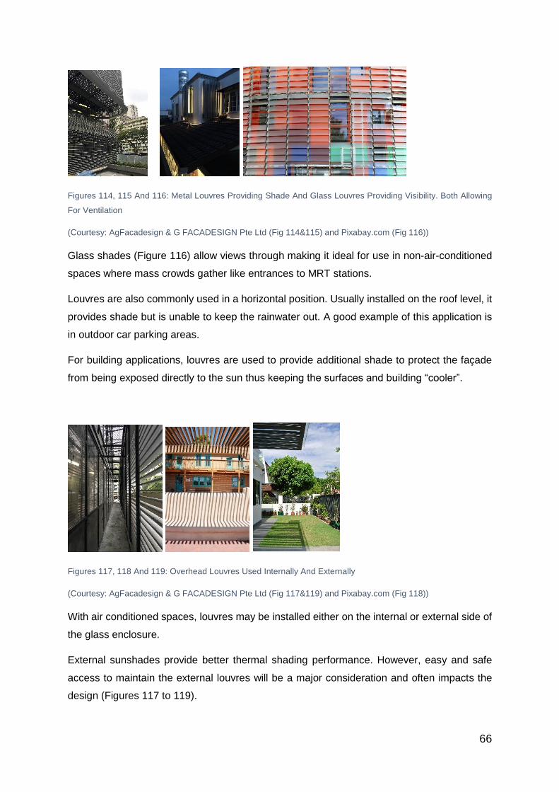
66
Figures 114, 115 And 116: Metal Louvres Providing Shade And Glass Louvres Providing Visibility. Both Allowing
For Ventilation
(Courtesy: AgFacadesign & G FACADESIGN Pte Ltd (Fig 114&115) and Pixabay.com (Fig 116))
Glass shades (Figure 116) allow views through making it ideal for use in non-air-conditioned
spaces where mass crowds gather like entrances to MRT stations.
Louvres are also commonly used in a horizontal position. Usually installed on the roof level, it
provides shade but is unable to keep the rainwater out. A good example of this application is
in outdoor car parking areas.
For building applications, louvres are used to provide additional shade to protect the façade
from being exposed directly to the sun thus keeping the surfaces and building “cooler”.
Figures 117, 118 And 119: Overhead Louvres Used Internally And Externally
(Courtesy: AgFacadesign & G FACADESIGN Pte Ltd (Fig 117&119) and Pixabay.com (Fig 118))
With air conditioned spaces, louvres may be installed either on the internal or external side of
the glass enclosure.
External sunshades provide better thermal shading performance. However, easy and safe
access to maintain the external louvres will be a major consideration and often impacts the
design (Figures 117 to 119).

67
12.3 Performance Louvres
The specification of performance louvres always involves compromises and requires some
judgement to take into account the particular needs of each application. At one end of the
scale, for example a car park may require maximum ventilation but little protection from rain
penetration. Alternatively, a plant room containing special machinery or electrical equipment
may still need high levels of ventilation but with maximum protection from water entry.
The ideal design solution is to produce a louvre system that offers the best rain defence and
aerodynamic performance. Unfortunately, this seems to be unachievable.
Considerations to be taken into account are:
a. Site location and exposure
b. Severity of local (site) weather conditions
c. Location and exposure of louvres on building
d. Airflow rate and direction through louvre
e. Maximum acceptable pressure drop
f. Acceptable degree and depth of water penetration
g. Special solutions for sloping applications
12.3.1 Water-Tight Louvres
In areas where water tightness is required, “weather-proof” louvres can be used (Figure 120).
To achieve water tightness, “double” or triple banks” louvres will be required. These
“performance louvres” are laboratory tested and provide a “water proof” effect of close to 100%
depending on the wind and rainfall conditions. Typical examples of weatherproof louvres are
found in sub-stations, which require good air ventilation as well as a dry environment.

68
Figure 120: Water-Tight Louvres (Courtesy: Patricia Collera)
12.3.2 Acoustic Louvres
In areas where noise will be a problem such as plant rooms, acoustic louvre panels can be
installed.
Plant room openings, cooling towers, substations, etc. typically produce noise levels which
may exceed existing or required noise control levels at prescribed distances from the building.
Acoustic louvres are mounted behind standard louvre panels and can help to reduce noise
egress (Figure 121).
For flexibility, the louvre panels can either be supplied partly pre-assembled, with the louvres
pre-cut to size and fitted with insulation and the frames supplied separately, or be supplied in
its component parts.
Figure 121: Acoustic Louvres (Courtesy: AgFacadesign & G FACADESIGN Pte Ltd)
12.3.3 Sand Trap Louvres
Although not an issue in tropical countries like Singapore, in arid areas, the provision of natural
inlet ventilation is essential in commercial and industrial premises if a satisfactory environment
is to be maintained. Yet providing this ventilation invariably allows sand to penetrate into the

69
building causing discomfort to personnel and possible damage to machinery (Figures 122 and
123).
How do sand trap louvres work?
Airborne particles pass through a series of deflector louvres arranged such that the sand hits
the louvres. The sand’s forward momentum is arrested and the particles fall out of the
airstream. The sand falls out of the bottom of the louvre panel. Due to the panel’s configuration,
additional filters are not required and since it has no moving parts, it is virtually maintenance
free.

70
12.3.4 Optional Accessories
Depending on the location and its environment, bird and insect guards can be integrated
where required. Usually fitted to the panels in the factory, slight modifications to the basic
design and profiles can be incorporated to suit specific aesthetic requirements i.e. extended
cills, flashings, etc.
Figures 122 And 123: Sand Trap Louvres
(Courtesy: AgFacadesign & G FACADESIGN Pte Ltd)
12.3.4.1 Shades
Another form of protection from the sun is the use of screens.
“Breeze blocks”, usually made from precast concrete can be stacked up easily to provide an
effective screen against the harsh sunlight (Figures 124 to 126).
The “perforations” in the block allow air to flow through making it an “ideal” building block for
buildings in the tropics with natural ventilation and shades. Breeze blocks were very popular
in the 70’s and due to the interesting “patterns” that can be achieved, this has become a
favourite amongst some architects especially in passive energy design (Figures 127 to 129).
Figures 124, 125 And 126: Use Of Air Block In PJ Trade Centre
(Courtesy: AgFacadesign & G FACADESIGN Pte Ltd (Fig 124-126)
71
Figures 127, 128 And 129: Air Blocks With Different Profiles As Shades
(Courtesy: AgFacadesign & G FACADESIGN Pte Ltd)
Another form of shade is more for “shading” against rain rather than sunlight.
Ethylene tetrafluoroethylene (ETFE), an extremely lightweight plastic material can be formed
into “pillows” filled with air. This enables large areas to be easily covered with minimal
structural provision (Figures 130 and 131).
However, for thermal performance, such “ETFE pillows” are not very effective and is often
used in an open-air area. In tropical regions, such applications will be suitabe for night time
use but will have restricted use in the day.
Figures 130 And 131 ETFE Roof Canopy At Clarke Quay, Singapore
(Courtesy: Patricia Collera)
12.3.4.2 Indirect Lighting
There are 2 types of indirect light;
a. Natural Daylight
In architecture, a clerestory is a high section of wall that contains windows above eye level.
The purpose is to admit light, fresh air, or both.
Historically, clerestory (Figures 132 and 133) denoted an upper level of a Roman basilica or
of the nave of a Romanesque or Gothic church, the walls of which rise above the rooflines of
the lower aisles and are pierced with windows.

72
Figures 132 And 133: Clerestory Lights Figure 134: Skylight To Staircase
(Courtesy: AgFacadesign & G Facadesign Pte Ltd)
Figures 135, 136, 137, 138: Clerestory Lights
(Courtesy: AgFacadesign & G FACADESIGN Pte Ltd (Fig 135-137) and Pixabay.com (Fig 138))
Figures 139 And 140: Skylights And Natural Day-Lighting
(Courtesy: Dr Joseph Lim - Architect)
b. Artificial Lighting
Benefits of Indirect Lighting
Indirect linear fluorescent lighting directs light upwards towards the ceiling and, depending
upon placement within the space, may also provide light to upper walls (Figure 141).

73
Favorable attributes include, but are not limited to:
• Soft and even illumination – from light bouncing off surfaces instead of direct lighting
• Computer friendly – minimal or no glare problems created to the computer screens
• No visible lamp image – light fittings are designed to be concealed within ceiling profiles
• Increased perception of comfort within the space
• Light is applied to ceilings (and often, to upper walls)
Figure 141 Indirect Artificial Lighting (Courtesy: AgFacadesign & G Facadesign.com Pte Ltd)
12.3.5 Building-Integrated Photovoltaics (BIPV)
BIPV are photovoltaic materials that are used to replace conventional building materials in
parts of the building envelope such as the roof, skylights, or façades.
Since Singapore is located close to the equator, the sun path is generally in an “overhead”
position. The potential gain for the solar panels is maximised if they are placed on the roof as
the roof surface is most exposed along the sun path. However, due to limited land, buildings
in Singapore tend to be “high” rather than “low rise” in nature. This gives the buildings a much
higher façade area compared to roof surface areas.
Photovoltaics are more commonly found on low rise slab blocks like factories and individual
houses where the ratio of roof to façade areas is much higher compared to high rise buildings.
BIPV on façades in Singapore is in general not suitable due to the overhead sun angle along
the Equator. However, in some European countries like Spain, BIPV on façades is possible
due to the amount of sun exposure on their façades (Figures 142 and 143).
BIPVs are incorporated into the construction of new buildings as a principal or ancillary source
of electrical power, although existing buildings may be retrofitted with similar technology.
In certain countries, where a “power grid” system is available, excess energy generated from
solar panels can be sold to the national grid. However, this is not common in Singapore yet.
The advantage of integrated photovoltaics over more common non-integrated systems is that

74
the initial cost can be offset by reducing the amount spent on building materials and labor that
would normally be used to construct the part of the building that the BIPV modules replaces.
These advantages make BIPV one of the fastest growing segments of the photovoltaic
industry and is popular with owners.
The term building-applied photovoltaics (BAPV) is sometimes used to refer to photovoltaics
that are retrofit – integrated into the building after construction is complete. Most building-
integrated installations are actually BAPV.
Some manufacturers and builders differentiate new construction BIPV from BAPV
Figure 142: Photovoltaic Wall (Courtesy: Pixabay.com)
Figure 143: BIPV Façade With CIGS Film Solar Modules (Courtesy: Mansz-AG, www.manz.com)
After learning about façade evolvement, various types of façade systems and glass
technologies, we now move onto the practical aspects of the building process.

75
Chapter 13: Project Work Stages
It is important to understand the key phases involved in the architectural process and what the
key elements of the phases are.
The 3 key phases are:
a. Design Stage
b. Tender Process
c. On-site construction
The main activities are briefly summarised for each of the key phases as follows:
13.1 Architect Work Stages
The following will illustrate the main elements involved in the different stages:
13.1.1 Design Concept / Scheme Design
- Sketches, Building Forms and Massing 4, Planning / Authority Requirements, etc.
a. Design Development
- Building layouts, building service core5 efficiency and spatial planning designs, building
elevation design and aesthetics, etc.
a. Detail Design
- Space efficiency design and Gross Floor Area (GFA) calculations, window
fenestrations and elevations treatments, materials selection, etc.
13.1.2 Tender Preparation Stage
- Preparation of Working Drawings and Performance Specifications
4 Building forms and massing refer to the building shape seen three-dimensionally.
5 A building service core refers to the vertical space used by pedestrians for circulation in-
between floors. This includes elevators, staircase, and M&E (Mechanical & Electrical) services.
76
a. Tender Calling / Award
- Administering the tender process and conducting interviews, making
recommendations and award to contractors, etc
13.1.3 Site Commencement And Installation Stage
- Conduct and chair meetings, review and attend to design clarifications, conduct
inspections, etc
a. Completion Stage – preparation of handover documentations and review of “As-built”
drawings and compile operations manuals for maintenance
b. Authority Applications / Inspections – conduct on-site inspections with officers on
building compliances
c. Defects Period – establish works to be rectified within the defects period.
13.2 Design Stage
Building envelope design especially façades has progressed from the basic plaster and paint
to cladding, curtain wall and beyond. “Free form façades have also led to a new term called
“blob architecture” which used to be associated with “expensive”, “difficult to build”, etc.
However, such preconceived notions are no longer the case with the advent of computers and
drawing software. With the aid of information technology (IT), literally any form of façade
“skins” is possible not only in terms of constructing complex geometries on the computer but
its ability to transform the information into fabricated components and eventually onto site for
assembly.
One such example is the free form “monocoque skin” found in the ION Orchard shopping
complex building in Singapore.
The completed façade skin was first modelled on the computer to optimise the curvature for
the different façades. Where the curvature was too much, the panels were required to be
triangulated in order to achieve the required “bends” while identifying the maximum twist
permitted for the “flat” panels. Together with the steel structure members, glass panels were
identified and itemised individually in drawings, then fabricated in the fabrication yard before
being delivered to site. All members were assembled on-site with almost zero wastage.

77
Figures 144 And 145 Computer Simulation Of Canopy And Façade Elements
(Courtesy: Arup Singapore Pte Ltd)
13.2.1 3D Modelling
An example is the duty-free shop in Bangkok where 3D modelling was used in the design
stages to on-site installation (Figures 146 to 149).
Figure 146: 3D Modelling Figure 147: Structural Analysis
Figure 148: On-Site Construction Figure 149: Completion
(Courtesy : Arup Singapore Pte Ltd)

78
13.2.2 Structural Analysis
To support the modelling of the building, software for structural analysis is required to analyse
the behaviour of the elements (Figures 150 to 153). Checks are done mainly for deflection and
stress in the key components such as;
a. Structural frames
b. Connections
c. Glass and/or cladding panels
Figures 150 And 151: Structural Analysis Of Structural Frame And Glass
Figures 152 Steel Frame Figure 153: 3D Documentation
(Courtesy : Arup Singapore Pte Ltd)
From concept to detailed design, the information and drawings will be collated and together
with the performance specifications, these will form the tender documents (Figures 154 and
155).
Specialist façade contractors will price according to the tender documentation. Project
consultants assess their bids in terms of compliances, track record and experience before
making their recommendations to owners for award.

79
Figures 154 And 155: 3D Tender Documentation
(Courtesy: Arup Singapore Pte Ltd)
For façade works upon award, the critical activities are as follows:
13.2.3 Shop Drawings Preparation – for comments and approval by Consultant
Preparation for this can almost be instantaneous as the design intent has already been
established. It is also common to expect that any major technical issues would have been
addressed during the tender interview rounds of Question and Answer sessions.
13.2.4 Visual Mock-up (VMU) – to be erected, reviewed and approved by Client/Consultants
After award of the façade package, one of the critical and often most urgent items is to have
the VMU set up (Figures 156 to 162).
Usually erected on a full size scale of 1:1, the key objectives of the VMU are to review the
major and typical components of the façade assembly in terms of:
a. the overall size(s) of the members
b. colour and finishes of the components
c. visible connections and interfacing of different members and components
d. assembly sequence of erection
e. glass - internal and external impact
It is important to know which critical components to review and approve for works to proceed.
Due to urgency, most items in VMUs are often “simulated to look like what they should be” i.e.
they need not be the actual components if unavailable. However, glass will have to be the
actual component specified in the tender because it will need to be approved before the order
for glass fabrication can be made. Often the long procurement time is attributed to the time
required for glass processing.

80
One of the important objectives of VMU is also to obtain approval for items by having them
“signed off” as minimum benchmarks to follow. This minimises disputes during on-site
installation (Figures 163 and 164).
Figures 156, 157 And 158: VMU Of Glass Tonality In Day And Night Conditions
Figures 159 And 160: Close Up Of Glass Tonality In VMUs
Figure 161: VMU Of Monocoque Frame And Glass Condition
Figure 162: LED Lights In Façade
(Courtesy : AgFacadesign & G FACADESIGN Pte Ltd (Fig 156-162))

81
Figure 163 And 164: Record Of Approvals Documented
(Courtesy: AgFacadesign & G FACADESIGN Pte Ltd)
13.2.5 Performance Prototype Test (PPT) – to establish if the system and its components
as designed meet the performance requirements (Figures 165 to 167)
This is one of the most critical stages where actual components are assembled in full scale
for testing against the elements in simulated real life conditions. Typically the tests are done
to 1.5 times the design requirements.
Typical tests cover:
a. Structural performance on the framing system and glass
b. Leakage tests - for air and water
c. Destructive testing (to failure)
Most of the tests pertain to structural and leakage requirements.
Destructive tests are usually for items where safety is of utmost importance so the user knows
what the limits are before failure occurs which can be catastrophic in nature.
Figures 165, 166 And 167 Performance Test Assembly (Courtesy: Arup Singapore Pte Ltd)

82
13.2.6 Material Testing
In certain instances, only certain critical components and materials are required to be tested.
Typically, these are connections and materials where the performance requirements are of a
specific nature.
Figure 168, 169 And 170: Material Testing Diagrams For Glass And Bolts
(Courtesy: AgFacadesign & G Facadesign Pte Ltd)
Figures 171, 172 And 173: Material Testing Of Bolts
(Courtesy: AgFacadesign & G Facadesign Pte Ltd)

83
Building Envelope And Thermal Transfer Values
Section 3:
Introduction
Since early days, the primary aim of a shelter was to provide protection against the natural
elements and to provide thermal comfort. While design has evolved through the times, the
primary objective remains the same. It is thus necessary to understand the fundamentals of
heat transfer to ensure the most effective and suitable design.
The building envelope is the interface between the interior of the building and the outdoor
environment, including the walls, roof and foundation. By acting as a thermal barrier, the
building envelope plays an important role in regulating interior temperatures and helps to
determine the amount of energy required to maintain thermal comfort. Minimising heat transfer
through the building envelope is crucial for reducing the need for space heating and cooling.
In cold climates, the building envelope can reduce the amount of energy required for heating;
in hot climates, the building envelope can reduce the amount of energy required for cooling. It
is thus important that the building envelope should respond to the local climate.
Figure 174: Building Envelope (Credit: Hammerandhand.com)

84
Learning Outcomes For This Section (Chapter 14 And Chapter 15):
i. To understand the various methods of heat transfer
ii. To analyse key parameters that affect building envelope
iii. To calculate the performance of the different thermo-physical properties
iv. To analyse how different components of a building’s façade affect the thermal
transfer value
v. To determine the various ways to improve a building’s envelope performance
Chapter 14: Building Envelope
14.1 Roofs
Roof design and materials play an integral part in reducing the amount of air-conditioning
required in hot climates. Such design considerations and materials selection will increase the
amount of solar heat reflected, which coupled with proper insulation will result in reduced
amount of heat absorbed by the roof. Roofs serve as ready platforms for installing on-site
energy generation systems such as solar photovoltaic (PV) systems. Such systems can either
be installed as a rooftop array on the top of a building or integrated into building roofing tiles
or finishes as a building-integrated photovoltaic system (BIPV).
14.2 Walls
Similarly, the amount of energy lost or retained through walls is also dependent on both design
and materials. Design considerations such as placement of windows and doors, their sizes
and locations are instrumental and should be optimised to reduce energy losses. Materials
selection, including wall construction and insulation, can affect the building’s thermal
properties. Thermal mass buildings absorb energy slowly, have longer heat-retention
capability and thus effectively reduce fluctuations in indoor temperatures and overall heating
and cooling requirements.
14.3 Windows, Doors And Skylights
Collectively known as fenestrations, windows, exterior doors and skylights affect both the
lighting and HVAC requirements of a building. While design influences the amount of available
natural lighting transmitted through fenestrations, material and installation influence the
amount of energy transmitted and air leakages through the fenestrations. Emerging materials,

85
coatings and designs have all contributed to the improved energy efficiency of high-performing
windows, doors and buildings. Recent technology for windows include multiple glazing, which
is the use of two or more panes of glass, layered with insulating films, or air gap filled with low-
conductivity gas such as argon, or coated with low-emissivity (low-E) coatings, which functions
to reduce the flow of heat energy between the building and the environment.

86
Chapter 15: Key Parameters Affecting Building Envelope
15.1 Massing And Building Orientation
It is important to consider building geometry as part of passive design strategy, to ensure that
exposure to the sun at different times of the day, building height and width can be optimised
for passive comfort.
Strategies for a passive massing and orientation depends on climate. It is important to note
that the sun path depends largely on the geographical location. Figure 175 below shows the
different sun path diagrams for a similar development in (a) Singapore, (b) Canada and (c)
Australia.
(a) (b) (c)
Figure 175: Comparison Of Annual Sun Path Diagram
The strategies for passive building envelope design should not be confused with those for
daylighting. Some important points to note:
a) The amount of sunlight required for daylighting is not optimal for solar heat gain.
b) While daylight comes from all directions, the heat from the sun is dependent on its solar
orientation. Façades facing away from the sun’s path can still get sufficient amount of
diffused light required for daylighting and will not get significant heat gain.
c) The heat from the sun can be stored by thermal mass while the sun’s light cannot. This is
an important consideration when designing the window and wall fabric for the west-facing
façade.

87
The orientation of the building can affect the choice of material and glazing to be used.
Taller buildings with a lower roof area per unit volume are able to reduce unwanted heat gain
in hot climates like Singapore.
As mentioned, walls facing the sun’s path get the most light as well as heat. Windows and
walls on the east façade are warmed in the morning, while those in the west façade are heated
in the afternoon. To even out the temperature gain, the façades on the west should be
designed with better insulation and low thermal mass to reduce the amount of heat absorbed.
Figure 176: Orientation Of Building (Credit: Wikipedia.org)
88
15.2 Window To Wall Ratio
The window to wall ratio (WWR) is the percentage that results from dividing the total glazed
area of the building by the total exterior wall area. The following examples below provide a
better understanding of WWR.
Total Wall area = 100m2
Window Area = 20m2
Window to Wall Ratio (WWR) = (20
100) = 0.2
Should the wall area remain the same, and the number of windows doubled,
the WWR would thus be (40
100) = 0.4
10m
10m
5m
4m

89
15.3 Wall Fabric
The wall fabric forms the interface between the inside and outside of a building. It has a
tremendous impact on the climatic regulation, energy consumption as well as the building’s
overall carbon intensity. The thermal performance of a wall fabric is thus dependent on the
heat transfer across the materials of the wall fabric.
There are three basic methods of heat transfer; conduction, convection and radiation. It is
important to understand heat transfer in order to determine the allowances for thermal
movement in terms of contraction and expansion, as well as to calculate the energy efficiency
of the wall design.
Conduction: The transfer of heat across a temperature gradient through direct molecular
contact. This can occur either through a single material or through multiple materials. For solid
building materials, this is the method by which most heat is transferred. Exterior walls made
for highly conductive heat flow can thus result in significant heat gain if not thermally isolated.
Convection: The transfer of heat across a temperature gradient through fluids (liquids, gases).
Convective heat and mass transfer take place both by diffusion and advection.
90
Radiation: The transfer of heat by electromagnetic waves through a vacuum or transparent
medium (solid or fluid). This is a result of random movements of atoms and molecules in
matter.
Figure 177: Modes Of Heat Transfer (Credit: chem1.com)
15.4 Thermo-Physical Properties
The different thermo-physical properties of building materials are discussed below:
15.4.1 Thermal Conductivity (K-Value)
Thermal conductivity is the quantity of heat transmitted under steady state conditions through
unit area of material of unit thickness in unit time when unit temperature difference exists
between the opposite sides. Thermal conductivity describes the ability of a material to conduct
heat and the unit is W/mK.

91
Figure 178: Heat Conduction Across Material (Image Credit: Openstax College Physics)
The thermal conductivity of some typical materials is given in Table 2 below:
Table 2: Thermal Conductivity Of Typical Materials. (Table extracted from BCA “Guidelines on Envelope Thermal
Transfer Value for Buildings)

92
15.4.2 Thermal Resistivity (r)
Thermal resistivity is the reciprocal of thermal conductivity. It is expressed in mK/W and is
given by:
r = 𝟏
𝒌
It can be defined as the time required for one unit of heat to pass through unit area of a material
of unit thickness when unit temperature difference exists between opposite faces. Thermal
resistance is the ability of a material to resist heat flow.
15.4.3 Thermal Conductance (c)
Thermal conductance refers to specific thickness of a material or construction. It is the thermal
transmission through unit area of a material per unit temperature difference between the hot
and cold faces. It is expressed in W/m2K and is given by:
c = 𝒌
𝒃
where b is the thickness of the material (m)

93
15.4.4 Surface Air Film Resistance
The presence of a thin layer of air above the surface of a material adds to the insulating
properties of a construction. These static layers of air on both sides of a wall provide additional
resistance and results in a temperature drop across the layer of air.
The air resistance results from convention currents at the surface of a material and is affected
by wind velocity. The outside and inside air films would therefore have different resistance
values. These are defined as:
Ro : air film resistance of external surface (moving air)
Ri : air film resistance of internal surface (still air)
Table 3: Surface Film Resistance For Walls And Roofs (Table Extracted From BCA “Guidelines On Envelope
Thermal Transfer Value For Buildings)
Type of Surface Thermal Resistance
(m2K/W)
A. Surface Film Resistance for Walls
1. Inside Surface (Ri)
(a) High Emissivity
(b) Low Emissivity
2. Outside surface (Ro) – High emissivity
0.120
0.299
0.044
B. Surface Film Resistance for Roof
1. Inside Surface (Ri)
(a) High Emissivity
(i) Flat roof
(ii) Sloped roof 22½ o
(iii) Sloped roof 45o
(b) Low Emissivity
(i) Flat roof
(ii) Sloped roof 22½ o
(iii) Sloped roof 45o
2. Outside surface (Ro) – High emissivity
Flat or sloped
0.162
0.148
0.133
0.801
0.595
0.391
0.055

94
15.5 Thermal Transmittance (U-Value)
The thermal transmittance of a construction is defined as the quantity of heat that flows
through a unit area of a building section under steady-state conditions in unit time per unit
temperature difference of the air on either side of the section.
The thermal transmittance of a construction takes into account losses due to thermal radiation,
thermal convection and thermal conduction. Well insulated walls have a low thermal
transmittance while poorly insulated walls have a high transmittance. The lower the U-value,
the lower the heat flow and this results in greater energy savings as a lower amount of energy
is required to maintain a constant room temperature.
Thermal transmittance of wall depends on the following factors:
a) Material layers
b) Thickness of materials
c) Thermal conductivity of material
d) Air resistance
It is expressed in W/m2K and is given by:
U = 𝟏
𝑹𝑻
Where RT is the total thermal resistance and is given by:
𝑅𝑇 = 𝑅𝑜 +𝑏1
𝑘1+
𝑏2
𝑘2+ ⋯ +
𝑏𝑛
𝑘𝑛+ 𝑅𝑖
Where
Ro : air film resistance of external surface (m2K/W)
Ri : air film resistance of internal surface (m2K/W)
k1, k2, kn : thermal conductivity of basic material (W/mK)
b1, b2, bn : thickness of basic material (m)

95
Example:
Layer Thickness
(mm)
Thermal
Conductivity
(W/mk)
Thermal
Resistance
(m2k/W)
External air film 0.040
External wall plaster 18 0.533 0.034
Brickwall 200 0.807 0.248
Internal wall plaster 18 0.533 0.034
Internal surface 0.120
Total R 0.475
U-Value = (1/R) = 2.104 W/m2k
External
Surface
200
18 18

96
15.6 Thermal Transmittance (U-Value) Of Fenestration
The U-value of a fenestration system measures the rate of non-solar heat gain or loss through
the assembly, which includes the effect of the frame, glass, seal and spacers if any. Again,
the lower the U-value, the greater is the window’s resistance to heat flow across the assembly.
The U-Value of the glass depends on:
a) Glass Thickness
b) Air Gap
c) Low Emissivity Coating
Typical U-values of various glass types can be found in table 4 below:
Table 4: U values of different glazing
Glazing Type U-Value (W/m2K)
Single Pane 4.8
Double pane, air filled 2.5
Double pane, low-E 2.1
Triple pane 2.1
Triple pane, low-E 1.4
15.7 Air Space Resistance
Air is a poor conductor of heat. If there is an air space between 2 layers of wall or roof
construction, the air trapped between the 2 layers acts as a barrier to heat transfer due to the
poor conduction of heat.
Heat is transferred across the air space by conduction, convection and radiation. The
effectiveness of the air space as an insulation layer is thus dependent on the thickness of the
air gap. Typical values of thermal resistance for air cavities are provided in table 5:

97
Table 5: Air Space Resistances For Walls And Roofs (Table Extracted From BCA “Guidelines on Envelope
Thermal Transfer Value for Buildings)
Type of Air Space
Thermal Resistances
(m2K/W)
5mm 20mm 100mm
A Air Space Resistances (Ra) for walls
Vertical air space (Heat flows horizontally)
(a) High emissivity 0.110 0.148 0.160
(b) Low emissivity 0.250 0.578 0.606
B Air Space Resistances (Ra) for Roofs
Horizontal or sloping air space (Heat flows horizontally)
(a) High emissivity
(i) horizontal air space 0.110 0.148 0.174
(ii) sloped air space 22.5o 0.110 0.148 0.165
(iii) sloped air space 45o 0.110 0.148 0.158
(b) Low emissivity
(i) horizontal air space 0.250 0.572 1.423
(ii) sloped air space 22.5o 0.250 0.571 1.095
(iii) sloped air space 45o 0.250 0.570 0.768
C Attic space resistance (R attic)
(a) High emissivity 0.458
(b) Low emissivity 1.356
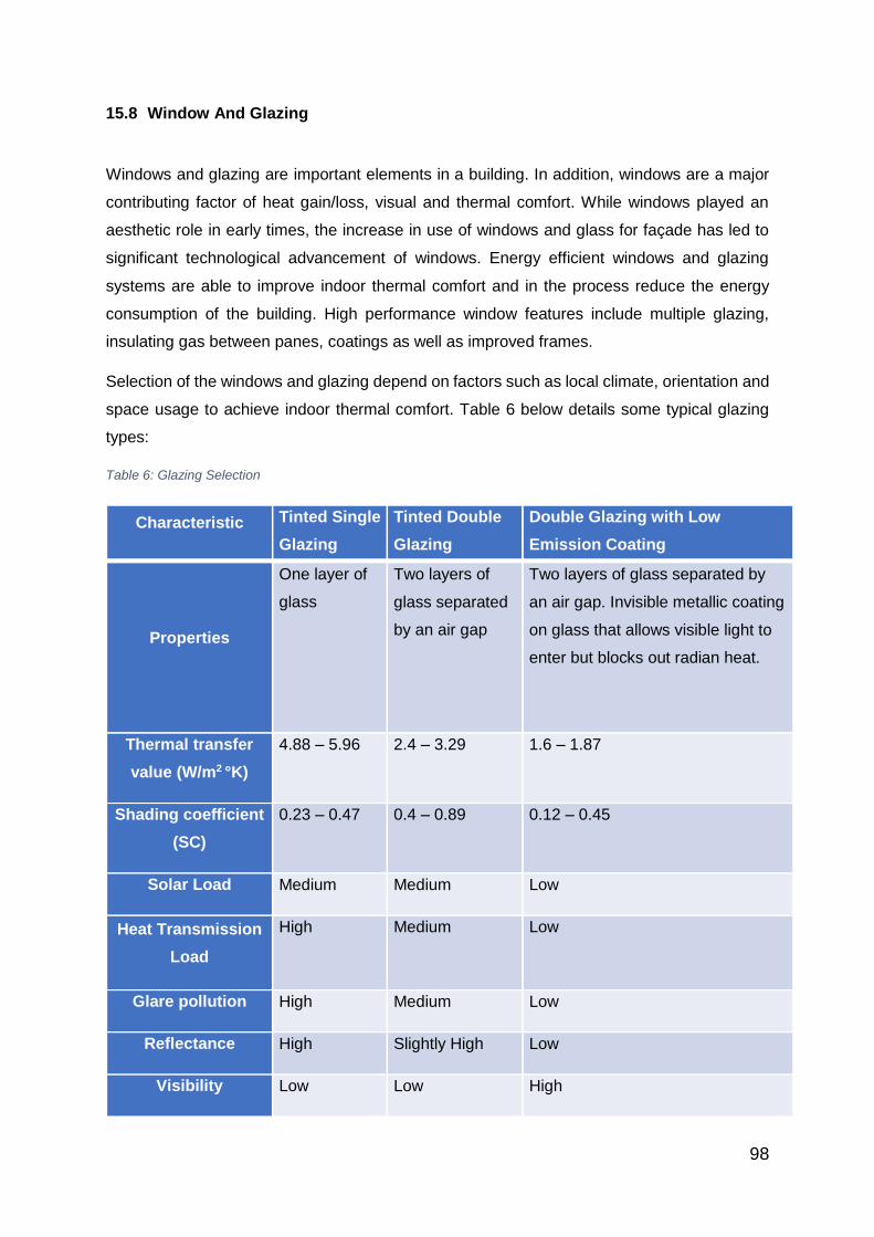
98
15.8 Window And Glazing
Windows and glazing are important elements in a building. In addition, windows are a major
contributing factor of heat gain/loss, visual and thermal comfort. While windows played an
aesthetic role in early times, the increase in use of windows and glass for façade has led to
significant technological advancement of windows. Energy efficient windows and glazing
systems are able to improve indoor thermal comfort and in the process reduce the energy
consumption of the building. High performance window features include multiple glazing,
insulating gas between panes, coatings as well as improved frames.
Selection of the windows and glazing depend on factors such as local climate, orientation and
space usage to achieve indoor thermal comfort. Table 6 below details some typical glazing
types:
Table 6: Glazing Selection
Characteristic Tinted Single
Glazing
Tinted Double
Glazing
Double Glazing with Low
Emission Coating
Properties
One layer of
glass
Two layers of
glass separated
by an air gap
Two layers of glass separated by
an air gap. Invisible metallic coating
on glass that allows visible light to
enter but blocks out radian heat.
Thermal transfer
value (W/m2 °K)
4.88 – 5.96 2.4 – 3.29 1.6 – 1.87
Shading coefficient
(SC)
0.23 – 0.47 0.4 – 0.89 0.12 – 0.45
Solar Load Medium Medium Low
Heat Transmission
Load
High Medium Low
Glare pollution High Medium Low
Reflectance High Slightly High Low
Visibility Low Low High
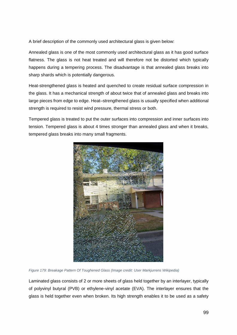
99
A brief description of the commonly used architectural glass is given below:
Annealed glass is one of the most commonly used architectural glass as it has good surface
flatness. The glass is not heat treated and will therefore not be distorted which typically
happens during a tempering process. The disadvantage is that annealed glass breaks into
sharp shards which is potentially dangerous.
Heat-strengthened glass is heated and quenched to create residual surface compression in
the glass. It has a mechanical strength of about twice that of annealed glass and breaks into
large pieces from edge to edge. Heat–strengthened glass is usually specified when additional
strength is required to resist wind pressure, thermal stress or both.
Tempered glass is treated to put the outer surfaces into compression and inner surfaces into
tension. Tempered glass is about 4 times stronger than annealed glass and when it breaks,
tempered glass breaks into many small fragments.
Figure 179: Breakage Pattern Of Toughened Glass (Image credit: User Markjurrens Wikipedia)
Laminated glass consists of 2 or more sheets of glass held together by an interlayer, typically
of polyvinyl butyral (PVB) or ethylene-vinyl acetate (EVA). The interlayer ensures that the
glass is held together even when broken. Its high strength enables it to be used as a safety

100
glazing and often in skylights. In addition, the interlayer provides protection from ultraviolet
rays as well as good acoustical characteristics due to its ability to absorb vibration.
Figure 180: Laminated Glass
Tinted glass with heat absorbing properties is made by adding colour pigments to the raw
materials in the float process. The colour density is dependent on the thickness. As the glass
gets thicker, the density of the colour increases and the amount of light transmittance
decreases. In reducing the transmittance of visible light, tinted glass also reduces the amount
of infrared radiation passing through.
Coated glass is often covered with a reflective or low-emissivity (low-E) coating. This coating
improves the thermal performance of the glass by reflecting visible light and infrared radiation,
while still maintaining a clear look. The low-E glass has a microscopically thin, transparent
coating that reflects long wave infrared energy as well as UV transmission.

101
Figure 181: Low- E Glass (Photo Credit: Efficient Windows Collaborative)
The coating is typically coated on one glass surface facing into the air gap. The surface to be
treated with low-E coating depends on the climate.
For climates dominated by the need for cooling, a low U-value and low SC is required. The
coating is usually coated on outer glazing (Surface #2), where it rejects most of the solar heat
gain.
For climates dominated by the need for heating, the need would be to block radiation from the
inside, thus the low- E coating would be coated on the interior glazing (Surface #3) for effective
passive solar heating applications where low U-value and high SC is required.
Insulating glass units consist of 2 or more panes of glass separated by a spacer material and
sealed together. The insulating airspace can be filled with air or other inert gases such as
argon or krypton, thereby improving the overall U-value of the window. In addition, when the
2 panes of glass have different thickness, the acoustical performance of the insulating glass
units is also greatly improved.
Surface #2 Surface #3

102
Figure 182: Types Of Insulating Glass (Photo Credit: Efficient Windows Collaborative)

103
15.9 Shading Devices
In tropical climates, external shading devices are very useful in keeping solar radiation off the
external façade of the building envelope. Special design consideration should be taken to
shade windows and transparent surfaces. External shading devices are often preferred to
internal ones as they are more effective.
The type of shading devices depends on building orientation and geographical location. For
locations with seasonal variation, the solar position is an important characteristic. For the
southern-hemisphere, the sun rises slightly south-east and sets slightly south west. In winter,
the sun rises slightly north-east and sets slightly north-west. The sun also rises earlier and
sets later in summer than in winter.
Figure 183: Sun Path Of A House In Southern Hemisphere

104
For a building in the southern hemisphere, the following guidelines would apply:
Orientation Effective Shading
North (Facing equator) Fixed horizontal device
East or West Vertical louvres
South (Facing Pole) Not required
The reverse would apply for a building in the northern hemisphere
Figure 184: Sun Path Of A House In Northern Hemisphere
Orientation Effective Shading
North (Facing equator) Not Required
East or West Vertical louvres
South (Facing Pole) Fixed horizontal device
For a building in the tropics, the sun path remains relatively the same throughout the year.

105
Figure 185: Sun Path Of A House In The Tropics
Orientation Effective Shading
North or South Fixed horizontal device
East or West Vertical louvres
When designing shading systems, fixed overhangs should be used to control direct beam
solar radiation. Indirect (diffuse) radiation should be controlled by the use of high performance
glazing.

106
Section 4:
Introduction
Envelope Thermal Transfer Value (ETTV) is a result of a review of the Overall Thermal
Transfer Value (OTTV) previously used to regulate the design of air-conditioned buildings.
Buildings must be designed to have an OTTV of not more than 45W/m2. It was however found
that OTTV did not accurately reflect the relative performance of the different elements in an
envelope system. It was found that OTTV underestimated the solar radiation gain component
through the fenestration system and hence did not represent the full extent of heat gain
through the envelope.
The OTTV was thus reviewed and a new formula that more accurately measures the thermal
performance of building envelope was derived and given the name ETTV.
ETTV formula consists of 3 basic components:
a) Heat conduction through opaque walls
b) Heat conduction through fenestration
c) Solar radiation through glass windows
These three components of heat input are averaged over the whole envelope area of the
building to give an ETTV that represents more accurately the thermal performance of the
envelope. For the purpose of energy conservation, the maximum permissible ETTV has been
set at 50W/m2. The baseline has been tightened to 45W/m2 with the launch of BCA Green
Mark for New Buildings (Non-Residential) 2015.
Learning Outcomes for Chapter 16 to Chapter 18:
i. To understand the importance of the development of ETTV
ii. To determine the 3 basic components of ETTV
iii. To identify the various components in the ETTV formula
iv. To extract the necessary data from the various tables provided in the BCA “Code on
Envelope Thermal Transfer Value for Buildings.”
v. To analyse the effectiveness of the different types of shading devices
vi. To calculate the ETTV of different types of building façade

107
Chapter 16: Envelope Thermal Transfer Value (ETTV)
16.1 Formula
𝑬𝑻𝑻𝑽 = 𝟏𝟐(𝟏 − 𝑾𝑾𝑹)𝑼𝒘 + 𝟑. 𝟒(𝐖𝐖𝐑)𝑼𝒇 + 𝟐𝟏𝟏(𝐖𝐖𝐑)(𝐂𝐅)(𝐒𝐂)
Where
ETTV : envelope thermal transfer value (W/m2)
WWR : window-to-wall ratio (fenestration area / gross area of external wall)
Uw : thermal transmittance of opaque wall (W/m
2K)
Uf : thermal transmittance of fenestration (W/m2K)
CF : correction factor for solar heat gain through fenestration
SC : shading coefficients of fenestration
Where more than one type of material and/or fenestration is used, the respective term or
terms shall be expanded into sub-elements as shown:
Where
Aw1, Aw2, Awn : areas of different opaque wall (m2)
Af1, Af2, Afn : areas of different fenestration (m2)
A0 : gross area
Uw1, Uw2, Uwn : thermal transmittances of opaque walls (W/m2K)
Uf1, Uf2, Ufn : thermal transmittances of fenestrations (W/m2K)
SCf1, SCf2, SCfn : shading coefficients of fenestrations

108
16.2 Solar Correction Factor (CF)
The solar correction factors for the eight primary orientations of the walls have been
determined for the Singapore climate. These can be found in Table 7 below:
Table 7: Solar Correction Factors (CF) For Walls (ETTV) (Table Extracted From BCA “Code On Envelope
Thermal Transfer Value for Buildings” Table C1)
For curved walls, the eight primary orientations are segmented as follows:

109
16.3 Roof Thermal Transfer Value (RTTV)
The concept of ETTV would apply to an air-conditioned roof with a skylight opening. The
term RTTV is used to differentiate between the walls and roof of a building.
RTTV formula consists of 3 basic components:
d) Heat conduction through opaque roof
e) Heat conduction through skylight
f) Solar radiation through skylight
The maximum permissible RTTV is 50W/m2
16.3.1 Formula For RTTV
𝑹𝑻𝑻𝑽 = 𝟏𝟐. 𝟓(𝟏 − 𝑺𝑲𝑹)𝑼𝒓 + 𝟒. 𝟖(𝐒𝐊𝐑)𝑼𝒔 + 𝟒𝟖𝟓(𝐒𝐊𝐑)(𝐂𝐅)(𝐒𝐂)
Where
RTTV : roof thermal transfer value (W/m2)
SKR : skylight ratio of roof (skylight area / gross area of roof)
Ur : thermal transmittance of opaque roof (W/m
2K)
Us : thermal transmittance of skylight area (W/m2K)
CF : correction factor for roof
SC : shading coefficients of skylight portion of the roof

110
Chapter 17: Residential Thermal Transfer Value
17.1 Residential Thermal Transfer Value (RETV)
The RETV calculation is largely similar to the ETTV calculation and applies to residential
buildings. The RETV formula consists of 3 basic components:
a) Heat conduction through opaque walls
b) Heat conduction through glass windows
c) Solar radiation through glass windows
The maximum permissible RETV has been set at 25W/m2
17.1.1 Formula For RETV
𝑹𝑬𝑻𝑽 = 𝟑. 𝟒(𝟏 − 𝑾𝑾𝑹)𝑼𝒘 + 𝟏. 𝟑(𝐖𝐖𝐑)𝑼𝒇 + 𝟓𝟖. 𝟔(𝐖𝐖𝐑)(𝐂𝐅)(𝐒𝐂)
Where
RETV : envelope thermal transfer value (W/m2)
WWR : window-to-wall ratio (fenestration area / gross area of external wall)
Uw : thermal transmittance of opaque wall (W/m
2K)
Uf : thermal transmittance of fenestration (W/m2K)
CF : correction factor for solar heat gain through fenestration
SC : shading coefficients of fenestration
17.1.2 Deem-To-Satisfy Criteria For RETV
Should the building’s WWR and SC fall within any of the following sets of criteria, the
building is deemed to have complied with RETV and hence exempted from computing RETV
WWRBldg SCfaçade
< 0.3 < 0.7
< 0.4 < 0.5
< 0.5 < 0.43
Where
WWR : Window to wall ratio

111
SC : Shading coefficient of fenestration = SCGlass X SCshading device
17.2 Shading Coefficient
The rate of solar heat gain through a fenestration system is altered by the shading
coefficient, which is defined as the ratio of heat gain through the fenestration system having
combination of glazing and shading device to the solar heat gain through an unshaded 3mm
clear glass.
𝑆𝐶 = Solar heat gain of any glass and shading combination
𝑆𝑜𝑙𝑎𝑟 ℎ𝑒𝑎𝑡 𝑔𝑎𝑖𝑛 𝑡ℎ𝑟𝑜𝑢𝑔ℎ 𝑎 3𝑚𝑚 𝑢𝑛𝑠ℎ𝑎𝑑𝑒𝑑 𝑐𝑙𝑒𝑎𝑟 𝑔𝑙𝑎𝑠𝑠
The shading coefficient of any fenestration system can be obtained as follows:
SC = SC1 x SC2
Where
SC: shading coefficient of the fenestration system
SC1: shading coefficient of glass or effective shading coefficient of glass with
solar control film where a solar control film is used on the glass
SC2: effective shading coefficient of external shading devices
It should be noted that the shading coefficient of the glass (SC1) should be based on the
manufacturer’s recommended value.
The effective shading coefficient (SC2) of external device can be obtained in Tables C12 to
C23 of the BCA “Code on Envelope Thermal Performance for Buildings” and will be discussed
briefly below. In cases where the type of shading device is not included in the table, the
effective shading coefficient shall be calculated from the basic solar data based on first
principles, in accordance with the method specified in the guideline.
Alternatively, the shading coefficient can be obtained by the use of software to obtain solar
insolation data.

112
17.3 Types Of External Shading Devices
17.3.1 Horizontal Projections
Figure 186: Horizontal Projections (Extracted From BCA Code On Envelope Thermal Performance For Buildings,
Section B4.1)
Figure 187: Effective Shading Coefficients Of Horizontal Projection (Extracted From BCA Code On Envelope
Thermal Performance For Buildings, Section B4.1)
Example (Extracted from BCA Code On Envelope Thermal Performance For Buildings,
Section B5.1)
Given : Window on South-West facing wall with a 0.3m horizontal overhang.
Find : The effective shading coefficient if (a) height of window is 0.6m; (b) height of
window is 0.75m with the overhang inclined at 30o to the horizontal.
Solution: Refer to Table C15
a) R1 = 0.5 SC = 0.698
b) R1 = 0.4 SC = 0.669

113
17.3.2 Vertical Projections
Figure 188: Vertical Projections (Extracted From BCA Code On Envelope Thermal Performance For Buildings,
Section B4.2)
Figure 189: Effective Shading Coefficients Of Vertical Projection For North And South (Extracted From BCA
Code On Envelope Thermal Performance For Buildings, Table C16)
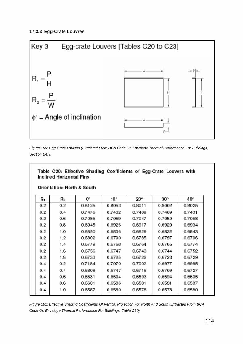
114
17.3.3 Egg-Crate Louvres
Figure 190: Egg-Crate Louvres (Extracted From BCA Code On Envelope Thermal Performance For Buildings,
Section B4.3)
Figure 191: Effective Shading Coefficients Of Vertical Projection For North And South (Extracted From BCA
Code On Envelope Thermal Performance For Buildings, Table C20)
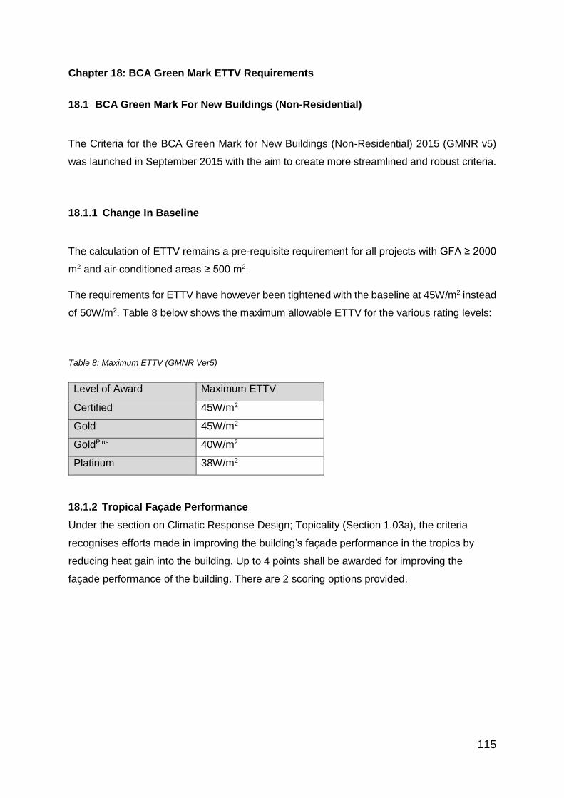
115
Chapter 18: BCA Green Mark ETTV Requirements
18.1 BCA Green Mark For New Buildings (Non-Residential)
The Criteria for the BCA Green Mark for New Buildings (Non-Residential) 2015 (GMNR v5)
was launched in September 2015 with the aim to create more streamlined and robust criteria.
18.1.1 Change In Baseline
The calculation of ETTV remains a pre-requisite requirement for all projects with GFA ≥ 2000
m2 and air-conditioned areas ≥ 500 m2.
The requirements for ETTV have however been tightened with the baseline at 45W/m2 instead
of 50W/m2. Table 8 below shows the maximum allowable ETTV for the various rating levels:
Table 8: Maximum ETTV (GMNR Ver5)
Level of Award Maximum ETTV
Certified 45W/m2
Gold 45W/m2
GoldPlus 40W/m2
Platinum 38W/m2
18.1.2 Tropical Façade Performance
Under the section on Climatic Response Design; Topicality (Section 1.03a), the criteria
recognises efforts made in improving the building’s façade performance in the tropics by
reducing heat gain into the building. Up to 4 points shall be awarded for improving the
façade performance of the building. There are 2 scoring options provided.

116
Example
Part 1
Given:
𝑬𝑻𝑻𝑽 = 𝟏𝟐(𝟏 − 𝑾𝑾𝑹)𝑼𝒘 + 𝟑. 𝟒(𝐖𝐖𝐑)𝑼𝒇 + 𝟐𝟏𝟏(𝐖𝐖𝐑)(𝐂𝐅)(𝐒𝐂)
Proposed Solution:
ETTVN = 12(1- 0.2) (2.7) + 3.4 (0.2)(5.82) + 211 (0.2)(0.57)(0.47) = 41.18W/m2
ETTVs = 46.52W/m2
ETTVE = 48.72W/m2
ETTVW = 49.11W/m2
ETTVT = 0.2 (ETTVN) + 0.2 (ETTVs) + 0.3 (ETTVE) + 0.3 (ETTVW)
= 46.89 W/m2

117
Part 2
From Part 1;
Given ETTV = 46.89 W/m2
What is the highest WWR possible to achieve ETTV of 50W/m2?
Proposed Solution:
𝑬𝑻𝑻𝑽 = 𝟏𝟐(𝟏 − 𝑾𝑾𝑹)𝑼𝒘 + 𝟑. 𝟒(𝐖𝐖𝐑)𝑼𝒇 + 𝟐𝟏𝟏(𝐖𝐖𝐑)(𝐂𝐅)(𝐒𝐂)
ETTVN = 12 (1-WWR) (2.7) + 3.4 (WWR) (5.82) + 211 (WWR) (0.57)(0.47)
= 32.4 (1-WWR) + 19.788 (WWR) + 56.527 (WWR)
= 32.4 – 32.4 WWR + 19.788 WWR + 56.527 WWR
= 32.4 + 43.915 WWR
ETTVS = 12 (1-WWR) (2.7) + 3.4 (WWR) (5.82) + 211 (WWR) (0.58)(0.68)
= 32.4 (1-WWR) + 19.788 (WWR) + 83.218 (WWR)
= 32.4 – 32.4 WWR + 19.788 WWR + 83.218 WWR
= 32.4 + 70.606 WWR
ETTVE = 12 (1-WWR) (2.7) + 3.4 (WWR) (5.82) + 211 (WWR) (0.77) (0.58)
= 32.4 (1-WWR) + 19.788 (WWR) + 94.233 (WWR)
= 32.4 – 32.4 WWR + 19.788 WWR + 94.233 WWR
= 32.4 + 81.621 WWR
ETTVE = 12 (1-WWR) (2.7) + 3.4 (WWR) (5.82) + 211 (WWR) (0.97) (0.47)
= 32.4 (1-WWR) + 19.788 (WWR) + 96.194 (WWR)
= 32.4 – 32.4 WWR + 19.788 WWR + 96.194 WWR
= 32.4 + 83.582 WWR

118
ETTVT = 0.2 (ETTVN) + 0.2 (ETTVs) + 0.3 (ETTVE) + 0.3 (ETTVW)
50 = 0.2 (32.4 + 43.915 WWR) + 0.2 (32.4 + 70.606 WWR) +0.3 (32.4 + 81.621 WWR) +
0.3 (32.4 + 83.582 WWR)
50 = 6.48 + 8.783 WWR + 6.48 + 14.121 WWR + 9.72 +24.486 WWR + 9.72 + 25.075
WWR
50 = 32.4 + 72.465 WWR
17.7 =72.465 WWR
WWR = 17.7/72.465 = 0.244
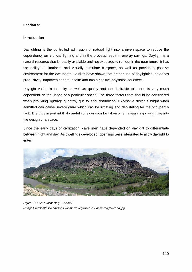
119
Section 5:
Introduction
Daylighting is the controlled admission of natural light into a given space to reduce the
dependency on artificial lighting and in the process result in energy savings. Daylight is a
natural resource that is readily available and not expected to run out in the near future. It has
the ability to illuminate and visually stimulate a space, as well as provide a positive
environment for the occupants. Studies have shown that proper use of daylighting increases
productivity, improves general health and has a positive physiological effect.
Daylight varies in intensity as well as quality and the desirable tolerance is very much
dependent on the usage of a particular space. The three factors that should be considered
when providing lighting: quantity, quality and distribution. Excessive direct sunlight when
admitted can cause severe glare which can be irritating and debilitating for the occupant’s
task. It is thus important that careful consideration be taken when integrating daylighting into
the design of a space.
Since the early days of civilization, cave men have depended on daylight to differentiate
between night and day. As dwellings developed, openings were integrated to allow daylight to
enter.
Figure 192: Cave Monastery, Erusheli.
(Image Credit: https://commons.wikimedia.org/wiki/File:Panorama_Wardzia.jpg)

120
From such crude openings, windows were later developed to control the flow of air, heat and
cold into a space. The primary function of a window was still the introduction of daylight into
a given space. While glass had been discovered as early as 3000BC in Egypt, it was used
mostly for decorative objects. During the Roman period, small pieces of hand –blown glass
set in bronze frames were used as infill for window openings.
While the mediaeval cathedrals had illustrious stained glass designs for daylighting, it was
only in the seventeenth century that advancement in manufacturing process allowed large
panes of glass to be used as window infills. This led to the wondrous interiors of the Baroque
churches.
Figure 193: Stained Glass (Image Credit: User Eusebius_Wikipedia)
Figure 194: Sunlight Shining Through Stained Glass (Image: User Ayyoubsabawiki-Wikipedia)

121
Daylighting remained the primary means of lighting for all types of buildings until the light bulb
was made commercially available in 1880 by Thomas Edison. In the early twentieth century,
with the development of electric sources, the design for daylighting began to decline. With
reduction in floor to floor height due to economics of structure, daylight penetration into
buildings was reduced.
It was not until the recent energy crisis that people realised the need to reduce the reliance on
fossil fuels. The approach to reduce the electrical load in the buildings led to the return to an
understanding of the natural resource of daylight.
Learning Outcomes For This Section (Chapter 19 To Chapter 26):
i. To appreciate the importance of daylighting
ii. To analyse the advantages and disadvantages of daylighting
iii. To evaluate the different parameters that determine the effectiveness of daylighting
design
iv. To describe the various design tools used for daylighting design
v. To develop different design concepts for maximising daylighting

122
Chapter 19: Daylighting
19.1 Principles
Daylighting needs to be considered from the initial design stage of a building and requires a
holistic approach to design. Part of sustainable architecture is associated with minimising the
energy consumption in the operating of the building throughout its life. Daylighting does not
only reduce the dependency on artificial lighting and reduce electricity consumption of lighting,
it also reduces the cooling load of a space.
Daylighting design takes into account the following factors which will be discussed further in
the following chapters:
a. The siting of the building, taking into account its orientation, sun path and surrounding
buildings and landscape;
b. The function and purpose of the building as these will determine the floor height and
floor division. These have an impact on the daylight penetration as well as the building
costs;
c. The location and size of the windows, as these have a bearing on the control of heat
gain and loss, glare as well as provision of views. This will depend on the glass
selection and will be discussed in some detail later.
Chapter 20: The Sun
The Sun is our singular source of renewable energy and sits at the center of our solar system.
It emits energy in the form of electromagnetic radiation at a very large and relatively constant
rate. The sun produces 63MW/m2 of energy and has a brightness of about 6000 million
lumens. It is about 150 million km away and light from the sun takes about 8 minutes to reach
the earth.
Figure 195: Planets In The Solar System (Image Credit: User PlanetUser_Wikipedia)

123
The rate at which solar energy reaches a unit area on the earth is known as the solar irradiance
or insolation and the unit is W/m2. The earth absorbs about 70 percent of the total solar
irradiance (TSI) that falls on the outermost atmosphere of the Earth, the rest is reflected into
space. The TSI does not remain constant and varies with sunspots and solar weather
activities.
Figure196: Solar Irradiance Spectrum Above Atmosphere And At Surface (Image Credit: User
BenRG_Wikipedia)
20.1 Visible Light
Sunlight might appear white, but it actually consists of electromagnetic waves with a wide
range of wavelengths. This broad range of wavelengths is known as the electromagnetic
spectrum.
This spectrum is subdivided into regions in order of decreasing wavelength and increasing
energy and frequency. These regions as shown in Figure 197 below are radio waves,
microwaves, infrared (IR), visible light, ultraviolet (UV), X-rays and gamma-rays.

124
Figure197: Electromagnetic Spectrum
All electromagnetic radiation is light, however only a small portion of this radiation, called
visible light can be seen. The wavelengths in the visible light spectrum range from about 400
nanometres to 700 nanometres
Approximately 45% of the radiation energy from the sun is within the visible light range.
Light can be reflected and refracted.
Reflection occurs when the angle of reflection equals the angle of incidence.
Surface
Normal
Incident ray Reflected ray
Surface
Normal
Incident ray Reflected ray

125
Refraction is the bending of a wave when it enters a medium where its speed is different.
When light passes from a less dense to a denser medium, the light is refracted towards the
normal.
The bending occurs because light travels more slowly in a denser medium.
White light is actually made of a whole range of colours mixed together. When visible light
travels through a prism, it is separated into its different wavelengths and shows the various
colours that make up visible light.
Figure 198: Separation Of Light By A Prism According To Wavelength (Image Credit: D-Kuru/Wikipedia
Commons)
Light Beam
Normal
(B) Denser Medium (A) Less Dense Medium

126
Figure 199: Waves Of Light With Different Wavelengths (Image Courtesy Of Windows To The Universe)
When light of that particular wavelength strikes the retina of our eye, we perceive that specific
colour sensation.
When all the wavelengths of the visible light spectrum strike our eyes at the same time, we
perceive the colour white, which is a combination of all the colours of the visible light spectrum.
Similarly, if none of the wavelengths reach our eyes, we perceive the colour black, which is
merely the absence of the wavelengths within the visible light spectrum.

127
Chapter 21 Advantages And Disadvantages
21.1 Advantages
a. Its free
Solar energy is the most abundant natural resource available and most importantly it is
completely free. No electricity is required when designing for daylighting and this energy is not
likely to run out in the near future.
b. It minimises the use of artificial lighting, reduces electricity cost and lowers HVAC cost.
The main objective of daylighting is to minimise the dependency on artificial lighting. Electrical
lighting accounts for 20% of the total electrical energy consumption in a commercial building.
The waste heat generated by electrical lighting imposes additional heat loads on the building’s
mechanical cooling system. The energy savings from reduced electrical lighting through
daylighting design is about 10% to 30%. Actual savings depend on several factors such as
efficiency of the HVAC system, usage of building as well as the building footprint.
c. Impact on occupant comfort
Daylight regulates circadian rhythms and psychological mood. The human circadian system
consists of the biological process that regulates our sleep-wake cycle. It was found that without
exposure to normal 24-hour light –dark cycles, a person’s sleep- wake cycle can deviate by
as much as two hours a day.
The production of neurohormones regulates our patterns of alertness and sleepiness.
Exposure to sunlight increases the brain’s release of a hormone, serotonin, which boosts
mood and helps a person stay calm and focused. At night, darker light triggers the release of
melatonin, which causes drowsiness. Without sufficient exposure to daylight, a person’s
serotonin levels can dip and the levels of melatonin increase. This leads to a higher risk of
‘Seasonal Affected Disorder’ or SAD which affects a large number of people at certain times
of the year due to lack of sunlight.
Exposure to sunlight has been found to increase the production of Vitamin D, which has a
significant impact on bone health.

128
d. Humans have a natural attraction to sunlight
Studies have shown that humans have a natural attraction to sunlight as it increases occupant
satisfaction and productivity. Daylight also gives the occupant a psychological value of space
and a sense of security. It has been observed that a view of a natural scene through a window
can relieve stress.
From the commercial aspect, studies have been conducted on malls with skylights and those
without (Heschong-Mahone, 1999a; Heschong et al., 2002a). The most obvious difference
apart from the skylights, was that malls with skylights had generally higher ceilings and had
photo sensor control of the artificial lighting under the skylights. The higher ceiling created a
general sense of space within the mall.
After dark, the appearance of all the malls were found to be similar. By day however, the
illuminances under the skylights were often much higher than those provided by artificial
lighting in malls without skylights. It was found that malls with skylights had a higher sales
index over the duration of the opening hours than malls designed without the skylights.
Figure 200: Mall With Skylight (Image Credit: User VictoriaDFong_Wikipedia)
e. Colour rendering
Daylight is often considered the best source of light for good colour rendering as it matches
human visual response most closely. Daylight will almost always have a good light spectrum,
in the sense that it has a high CIE (The International Commission on Illumination) General
Colour Rendering Index.

129
21.2 Disadvantages
a. Fluctuation In Illumination
One major disadvantage of daylighting is the large fluctuation in illumination intensity caused
by movement of clouds across the sky as well as reflection from terrain and surrounding
buildings. Since we are unable to control or predict the movement of clouds and the natural
elements, careful consideration has to be taken to determine if a particular space is suitable
for daylighting.
Spaces where light intensity is not critical are suitable for daylighting. These include
staircases, corridors, toilets and lift lobbies. Such spaces are usually also equipped with photo
sensors so that the artificial light can be turned on or adjusted should the lux level fall below a
required level.
Figure 201: Fluctuation In Illumination Intensity
b. Undesirable Heat Gain
If not designed properly, direct sunlight falling directly incident on occupants near the window
can cause thermal discomfort. It is thus important that the glazing designed for daylighting
does not contribute to undesirable heat gain. If so, the added cooling load may offset any
savings from the decreased lighting cost.
The following chapters will discuss how to maximise daylighting designs to ensure that energy
savings achieved from reduced artificial lighting are not lost through increased cooling needs.

130
c. Glare
The purpose of daylighting is not only to provide sufficient illuminance levels for good
performance, but also to maintain a comfortable and pleasing atmosphere. Direct sunlight
penetration into a space can result if not designed properly and results in unpleasant glare.
Glare often refers to an area of intense brightness within the visual field and the difficulty in
seeing in the presence of bright light. The Illuminating Engineering Society (IES) defines glare
as one of two conditions: too much light, or excessive contrast, where the range of luminance
in the visual field is too great.
Glare can be experienced as discomfort glare or disability glare.
Discomfort glare is glare which is distracting or uncomfortable, and can interfere with the visual
perception but does not reduce the ability to see.
Disability glare is glare which reduces the ability to see and is usually caused by light scattered
within the eye, decreasing contrast and reducing visibility.
Figure 202: Example Of Glare: Excessive Contrast
The human eye is able to perceive light levels of less than 1 lux (equivalent to starlight) to
more than 100,000 lux (equivalent to a sunny day). The eye can however only adapt to a small
part of this range at one time and takes a few moments to adapt whenever the range changes.
This is apparent when you enter a dark tunnel on a sunny day and you are temporarily blinded
as your eyes are already adapted to the daylight. As you leave the tunnel, the external daylight
is temporarily glaring.
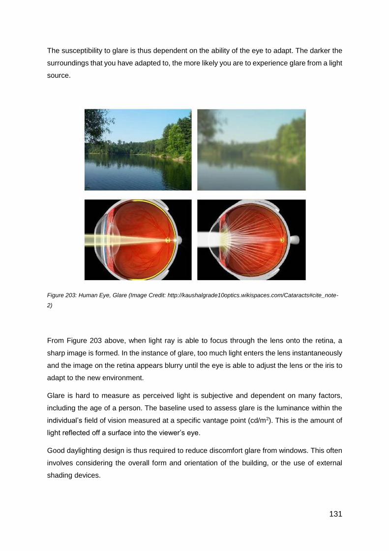
131
The susceptibility to glare is thus dependent on the ability of the eye to adapt. The darker the
surroundings that you have adapted to, the more likely you are to experience glare from a light
source.
Figure 203: Human Eye, Glare (Image Credit: http://kaushalgrade10optics.wikispaces.com/Cataracts#cite_note-
2)
From Figure 203 above, when light ray is able to focus through the lens onto the retina, a
sharp image is formed. In the instance of glare, too much light enters the lens instantaneously
and the image on the retina appears blurry until the eye is able to adjust the lens or the iris to
adapt to the new environment.
Glare is hard to measure as perceived light is subjective and dependent on many factors,
including the age of a person. The baseline used to assess glare is the luminance within the
individual’s field of vision measured at a specific vantage point (cd/m2). This is the amount of
light reflected off a surface into the viewer’s eye.
Good daylighting design is thus required to reduce discomfort glare from windows. This often
involves considering the overall form and orientation of the building, or the use of external
shading devices.

132
The Unified Glare Rating (UGR) is widely used as a general assessment of glare. The formula is given below:
𝑈𝐺𝑅 = 8 log [0.25
𝐿𝑏∑ (
𝐿2𝜔
𝑝2)]
Where
Lb is the background luminance
L is the luminance of the luminaire
P is the Guth index, which increases the further the luminaire is from the viewer’s line of sight
ω is the Solid angle of the light-emitting surface of each light relative to the observer’s eye
Thus, from the formula, it can be seen that glare increases with a stronger light source and
lower background light. Similarly, as the source moves further from the line of sight, glare as
measured by the UGR decreases.
Some points to note:
UGR < 10 is considered insignificant and can be ignored
UGR > 30 is considered excessive and might cause discomfort

133
Chapter 22: Design Parameters
Design parameters vary with the building applications and can be used to determine the most
suitable system to be used to achieve the design objective. Parameters include visual
performance and comfort, usage of the building and the integration with the building system.
The primary objective of daylighting design should be to provide usable daylight for the specific
building type, which allows natural daylight to offset the dependence on artificial lighting.
Design solutions should aim to maximise the usage of usable daylight in climates with
predominately overcast skies; reduce exterior obstructions to increase usable daylight and
transport usable daylight deeper into a given space or into windowless spaces.
22.1 Daylight Factor
Daylight factor (DF) is a measure of the amount of natural light in a space. It quantifies the
amount of light at a particular point relative to the instantaneous amount of daylight available
outside.
Daylight factor is defined as the ratio of the interior illuminance to the horizontal illuminance
under a standard overcast sky condition. It is expressed as a percentage; the higher the
daylight factor, the more natural light is available in the space.
Daylight factor can be expressed as:
𝑫𝑭 = 𝑬𝒊
𝑬𝟎𝑿𝟏𝟎𝟎 (%)

134
Where
Ei = illuminance due to daylight at a point on the indoors working plane
E0 = simultaneous outdoor illuminance on a horizontal plane from an unobstructed
hemisphere of overcast sky
Therefore, a DF of 4 % means that the indoor light is 4% of the available outside daylight.
SS531: Part 1
Below is an extract from SS531: Part 1 on Daylighting requirements:
Daylight may provide all or part of the lighting for visual tasks.
Daylight varies in level and spectral composition with time and therefore provides variability
within an interior. Daylight may create a specific modelling and luminance distribution due to
its nearly horizontal flow from side windows. Daylight can also be provided by roof lights and
other fenestration elements.
Windows can also provide a visual contact with the outside world, which is preferred by most
people. Avoid excessive contrast and thermal discomfort caused by direct sunlight in work
areas. Provide adequate sun control such as blinds and shades, so that direct sunlight does
not hit workers and/or surfaces within their field of view.
In interiors with side windows, the available daylight decreases rapidly with distance from the
window. In these interiors, the daylight factor should not fall below 1% on the working plane
3m from the window wall and 1m from side walls. Supplementary lighting should be provided
to achieve the required illuminance at the work place and to balance the luminance distribution
within the room. Automatic or manual switching and/or dimming can be used to ensure
appropriate integration between artificial lighting and daylight.
*Note: The above extract is reproduced with the kind permission of the International Organization for
Standardization (ISO). All rights reserved by ISO

135
22.2 Green Mark
Extracts of the Daylighting requirements from the BCA Green Mark Residential and Non-
Residential criteria can be found below
22.2.1 BCA Green Mark –Residential Criteria Version 4.1
22.2.2 BCA Green Mark – Non- Residential Criteria Version 4.1
*It should be noted that the various Green Mark criteria mentioned are the prevailing criteria
at the time of writing

136
22.3 LEED
Below are extracts of daylighting from the LEED Green Building Rating system Version 2.1
Credit 8.1
Achieve a minimum Daylight factor of 2% in 75% of all space occupied for critical visual
tasks. Spaces such as storage areas, mechanical plant rooms, laundry and other low
occupancy support areas are excluded from this requirement

137
Chapter 23: Design Principles
23.1 Types Of Skies
a. Uniform Sky
Characterised by a uniform luminance that does not change with altitude or azimuth.
Used from days when calculations were done by hand or tables and of Right of Light
cases.
b. Overcast Sky
Changes with altitude. Three times as bright in the zenith as it is near the horizon.
Used when measuring daylight factors.
b. Clear Sky
Luminance varies over both altitude and azimuth. Brightest around the sun and
dimmest opposite. Brightness of the horizon lies in between these extremes.
c. Intermediate Sky
Somewhat hazy variant of clear sky. Sky is not as bright as the clear sky and the
brightness changes are not as drastic.
Figure 204: Types Of Sky (CIE) (Credit: Comfortable Low Energy Architecture)
The CIE standard Overcast Sky is used to assume the luminance distribution of the sky when
determining the minimum contribution of daylight to an interior. This assumption does not take
into account sunlight.

138
23.2 Components Of Daylight
Daylight consists of the following components:
a) Direct Sun
b) Direct Sky
c) Externally Reflected
d) Internally Reflected
The Direct Sun and Direct Sky are light that reaches the measurement point directly from the
sky. The externally reflected component is daylight that reaches the measurement point after
reflection outside the room, either from natural or man-made structures. The internally
reflected component is daylight that arrives at the measurement point after reflection inside
the room.
Figure 205: Components Of Daylight
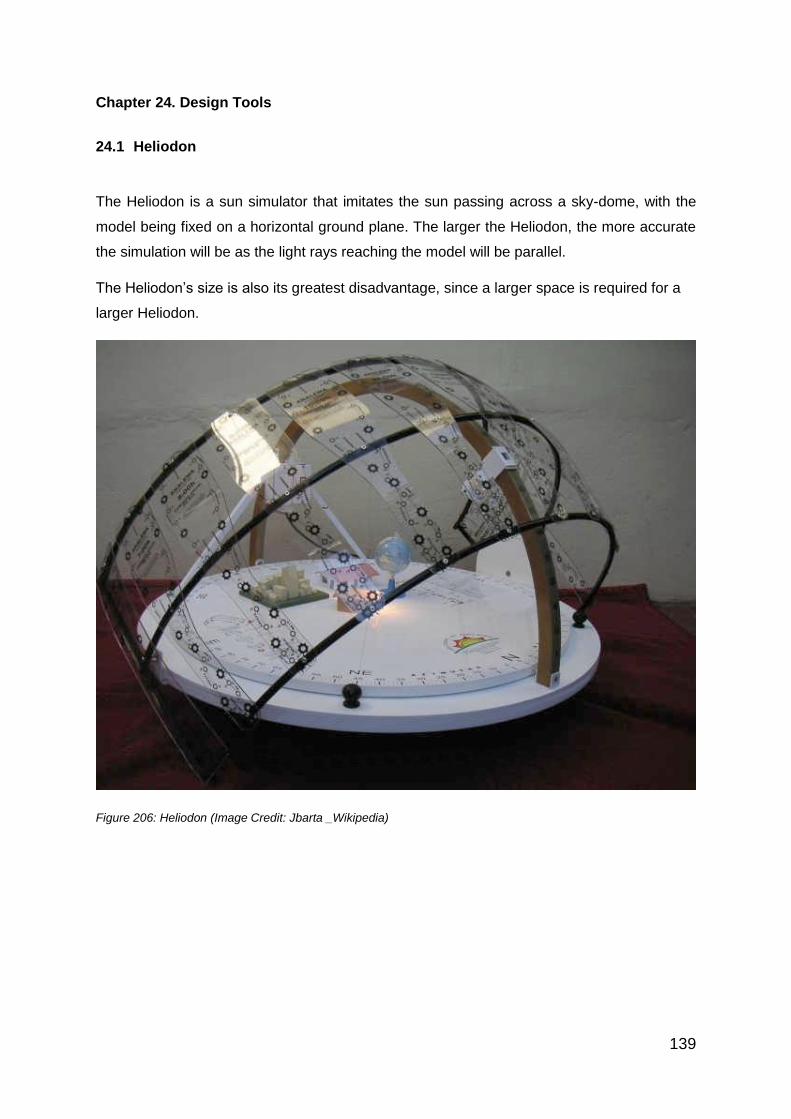
139
Chapter 24. Design Tools
24.1 Heliodon
The Heliodon is a sun simulator that imitates the sun passing across a sky-dome, with the
model being fixed on a horizontal ground plane. The larger the Heliodon, the more accurate
the simulation will be as the light rays reaching the model will be parallel.
The Heliodon’s size is also its greatest disadvantage, since a larger space is required for a
larger Heliodon.
Figure 206: Heliodon (Image Credit: Jbarta _Wikipedia)

140
24.2 Artificial Sky
An artificial sky allows the testing of scaled models under simulated standard CIE overcast
sky conditions. The daylighting performance of the proposed model can then be determined
and fine-tuned. The daylight factors can be measured with special multiple lux meters for
optimisation of daylighting. These are however expensive to set up and maintain and are being
replaced by computer models.
Figure 207: Box Shaped Artificial Sky (Image Credit Vashon Baker)
Figure 208: Artificial Sky Lab (Image Credit: User Vu K Hoang_Wikipedia)

141
24.3 Computer Modelling
With the advancement in technology and graphics techniques, computer simulations are more
commonly used to predict daylighting levels as well as solar insolation. The software allows
the accurate modelling of interiors to produce realistic images and quantified photometric
output.
Figure 209: Daylight Simulation Of House In Ecotect
Figure 210: Image Showing Solar Insolation Simulation

142
Chapter 25: Design Concept
25.1 Overview
Daylighting concepts involve the integration of the different disciplines of design. Daylighting
design should be integrated early in the design process to ensure that concepts and ideas are
carried out throughout the project.
The amount of daylight that penetrates a space depends on the window orientation, size and
glazing characteristics.
25.2 Daylight Penetration
The two factors that quantify daylight penetration are the amount and distance of daylight.
The amount of daylight that penetrates a space depends on the window orientation, size and
glazing properties. The distance that adequate daylight penetrates a room depends on the
window location and interior surfaces.
Typical adequate daylight should penetrate about one and a half times the height of the
window head.
Figure 211: Adequate Daylight Penetration

143
22.3.1 Light Shelves
The use of light shelves can increase the depth of penetration into a given space and are
most suitable for spaces with higher than average floor-to-ceiling height.
A light shelf is a horizontal element designed to shade and reflect light on its top surface and
shield direct glare from the sky. It is usually mounted horizontally on either side of the window
above eye height. The lower the height of the window, the greater amount of light is reflected
onto the internal ceiling.
Depending on the length of the light shelf, the depth of penetration can be increased to about
two and a half times the window height.
Figure 212: Increase Depth Of Penetration From Light Shelves
Light shelves can be mounted on the interior or exterior. Compared to those installed at the
exterior, light shelves on the interior reduce the amount of light brought into the space;
however the light distribution is more even.
For best results, light shelves should be mounted horizontally and the surface of the shelf
should be highly reflective. The surface can also be painted with a rougher, less mirror-like
finish to diffuse the spread of the incoming sunlight. Similarly, the ceiling should also be
painted with a light coloured reflective paint to allow the light to reflect further into the internal
space.

144
Figure 213: Reduction Of Glare
For workspaces along the building perimeter, light shelves are able to reduce the effect of
glare by directing the incoming light upwards towards the ceiling.
Light shelves can be constructed of any material, not necessarily metallic. Factors such as
construction cost, structural strength, ease of maintenance and aesthetics should be taken
into account when designing light shelves.

145
25.3 Building Orientation
To maximise the advantage from daylighting design, buildings should be orientated to take
advantage of the sun’s path throughout the day, and seasonal variations if any. A sun path
diagram allows the designers to strategically place openings to admit usable daylighting and
at the same time minimise low angle direct sunlight entering a space.
Figure 214: Annual Sun Path Diagram Of Singapore
For optimum daylight potential, the building should have their long axes running east and west,
instead of north-south. This orientation allows daylight to be harnessed consistently and
control glare along the long faces of the building. The glare from the rising and setting sun is
also minimised.
North
East West
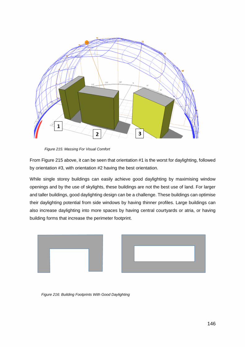
146
Figure 215: Massing For Visual Comfort
From Figure 215 above, it can be seen that orientation #1 is the worst for daylighting, followed
by orientation #3, with orientation #2 having the best orientation.
While single storey buildings can easily achieve good daylighting by maximising window
openings and by the use of skylights, these buildings are not the best use of land. For larger
and taller buildings, good daylighting design can be a challenge. These buildings can optimise
their daylighting potential from side windows by having thinner profiles. Large buildings can
also increase daylighting into more spaces by having central courtyards or atria, or having
building forms that increase the perimeter footprint.
Figure 216: Building Footprints With Good Daylighting

147
25.4 Window Orientation
Window orientation is largely dependent on the building orientation and Sun path. The greatest
amount of solar energy received through a window is when the sun is perpendicular to the
window and about 30 to 35 degrees above the horizon.
In Singapore’s context, our Sun path deviates little along the east and west axis. It is thus
advantageous to maximise window openings along the north and south façades. The diffused
light from the north and south façade will provide sufficient illuminance for interior lighting
needs while reducing solar heat gain.
Windows at the eastern and western façade should be minimised as these are where the sun
angle is the lowest and most likely to cause glare and excessive solar heat gain. Sunshades
can be added at these directions to minimise discomfort.
25.5 Window Performance
25.5.1 Solar Heat Gain
The Solar Heat Gain Coefficient (SHGC) measures the amount of solar energy through a
window. The SHGC can be measured for the entire window unit, including the frames, or for
just the glazed area. The higher the SHGC, the more solar energy is collected by the window.
Windows should have a lower SHGC to reduce heat gain from solar energy.
Figure 217: Solar Heat Gain (Source: Efficient Windows Collaborative)

148
25.5.2 Glazing
Glazing is an important element for daylighting and the simplest method to maximise daylight
within a space is to increase the glazing area. However, three characteristics of glass need to
be understood in order to optimise a fenestration system:
a) U-Value: represents the rate of heat transfer due to temperature difference through a
particular glazing material. The lower the U-value, the greater a glazing’s resistance to
heat flow and the better its insulating property.
b) Shading Coefficient (SC): a ratio of solar heat gain of a given glazing assembly
compared to double-strength, single glazing. It is a measure of how well a glazing
lowers solar heat gain from the sun. The shading coefficient is the percentage of the
incident solar radiation (both directly transmitted and absorbed) admitted through a
window, and subsequently released to the interior. It is expressed as a number
between 0 and 1. A lower value represents less solar heat transmitted and thus better
performance.
c) Visible Transmittance (VT): a measure of how much visible light is transmitted through
a given glazing material. It is expressed as a number between 0 and 1; the higher the
number, the more light is transmitted.
A high-performance glazing system will admit more light and less heat than a typical system.
The performance of a glazing material is often compared against a single pane of clear glass,
which will admit the most visible solar radiation, some infrared radiation and little ultraviolet
radiation.
Glazing materials can be altered to increase both thermal and optical performance. Glazing
manufacturers have a wide variety of tints, metallic and low-emissivity coatings, and fittings
available in their range of products. Other options include multi-paned glass panels filled with
air or other inert gases such as argon or krypton to improve U-values.
For effective daylighting in large buildings, the use of glass with moderate-to-low shading
coefficient and relatively high visible transmittance should be considered.

149
25.5.3 Switchable Glazing
Recent developments in glazing technology include glazing materials that can vary their
optical or solar properties according to the external stimuli such as light (photochromic), heat
(thermochromic) or electric current (electrochromic)
Figure 218: Photochromic Glass
Figure 219: Diagram Of Thermochromic Film (Image Credit Commercial Windows)
Figure 220: Diagram Of Electrochromic Coating (Image Credit: Commercial Windows)

150
25.6 Skylight
Skylights can provide satisfactory lighting for spaces that can tolerate large variations in
illumination levels. The major advantage of skylights is the ideal colour rendition of daylight.
Skylights have a positive effect on retailing, restaurants and public areas, providing a sense
of natural ambience. The major disadvantage is the large fluctuation in illumination intensity
that cannot be controlled, and this often results in annoyance. Spaces such as offices,
classrooms are thus not suitable for skylight applications.
Skylights should be installed at a high place to allow for daylight penetration and reduce the
likelihood of excessive brightness. It is better to have a large number of smaller skylights as
this would allow better distribution of light, less modification to the roof structure as well as
avoiding leakage problems.
Figure 221: Skylight Designs (Image Credit: Unicel Architectural)

151
25.7 Diffusion
Direct sunlight is usually not suitable for daylighting as it results in localised bright spots.
Diffusion of the direct sunlight minimises the changes in illumination intensity caused by the
motion of the sun.
Figure 222: Materials To Diffuse Direct Sunlight

152
25.8 Skylight Material
Skylights are commonly made from glass, glass composites, plastics and plastic composites.
All these materials can be treated to reduce light transmission and heat load.
The advantages and disadvantages of glass and plastic are summarised in the tables below:
Table 9: Glass As Skylight Material
Advantages Disadvantages
Unlimited life Vulnerability to breakage
High light transmission Weight
Hard, rigid
Can be coated to reduce UV
Table 10: Plastic As Skylight Material
Advantages Disadvantages
Light weight Buckling with age
Resistant to shattering Strength deteriorates with age
Easily moulded to reduce water
leakage
Reduction in light transmission
due to UV light, heat , oxidation
Can be reinforced with fibres to
diffuse light
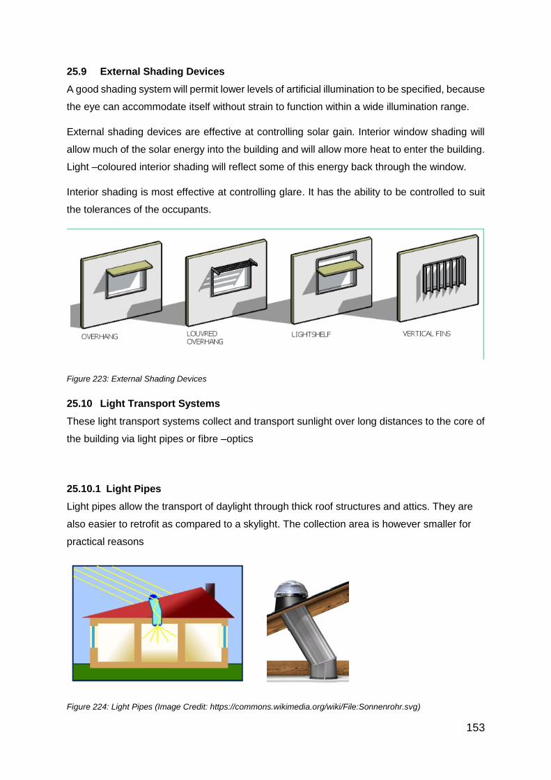
153
25.9 External Shading Devices
A good shading system will permit lower levels of artificial illumination to be specified, because
the eye can accommodate itself without strain to function within a wide illumination range.
External shading devices are effective at controlling solar gain. Interior window shading will
allow much of the solar energy into the building and will allow more heat to enter the building.
Light –coloured interior shading will reflect some of this energy back through the window.
Interior shading is most effective at controlling glare. It has the ability to be controlled to suit
the tolerances of the occupants.
Figure 223: External Shading Devices
25.10 Light Transport Systems
These light transport systems collect and transport sunlight over long distances to the core of
the building via light pipes or fibre –optics
25.10.1 Light Pipes
Light pipes allow the transport of daylight through thick roof structures and attics. They are
also easier to retrofit as compared to a skylight. The collection area is however smaller for
practical reasons
Figure 224: Light Pipes (Image Credit: https://commons.wikimedia.org/wiki/File:Sonnenrohr.svg)

154
Chapter 26: Controlling Lighting
It is desirable to control both artificial lighting within a space as well as the daylight entering it.
This allows the user to minimise the usage of electricity for artificial lighting, benefit from the
usage of daylight while maintaining the required level of illuminance.
26.1 Controlling Daylighting
The primary control of daylighting should be made by choice of window size and position. The
daylight transmittance of the glazing then determines the maximum light that can be received
in the room.
26.1.1 Manual Control
Manual control over the quantity and quality of daylight in the rooms can be provided either by
simple diffusing curtains or venetian blinds, or by more sophisticated light redirecting systems.
The latter aims to optimise the quantity and quality of the incident natural light and thus the
avoidance of glare.
26.1.2 Automatic Systems
Automatic systems can perform a wide range of control actions. They can tilt or turn horizontal
/ vertical lamellae, lower or raise curtains and rotate sun-tracking systems. Many of these
systems do not respond to overall daylight availability, but respond only to the direct sunlight
or solar position. The heliostat shown in figure 225 is based on solar position.
Figure 225: Mirror Heliostat (Image Credit: Comfortable Low Energy Architecture, Bartenbach Lichtlabor, Austria)

155
Daylight responsive daylighting control systems consist of a sensor to measure incident flux,
and a control system acting according to the sensor’s signal. An example of such system is
the fibre optics system
Figure 226: Fibre-Optic System
26.1.3 Case Study: Changi Airport Terminal 3
The Singapore Changi Airport Terminal 3 has a roof consisting of 919 skylights which allow
daylight into the terminal building. Direct sunlight is limited by the louvres suspended below
the skylight, thus flooding the terminal with diffused, ambient light.
Figure 227: Daylighting System In Changi Airport Terminal 3

156
Each skylight has its own shading system comprising 2 aluminium panels aligned like butterfly
wings. The aluminum reflectors ensure that maximum daylight is reflected to the terminal
below.
Figure 228: Cross Section Of Skylight At T3
Figure 229: Rooftop Installation Of Daylighting System In Changi Airport Terminal 3

157
The main terminal is aligned in an east-west orientation to maximise the daylight harvesting
potential. The computer controlled system, together with strategically placed sensors results
in an intelligent and efficient daylight system.
Figure 230: Daylighting System In Changi Airport Terminal 3
In the morning, the eastern wing of the skylight will be closed to reduce the direct sunlight
entering the shaft. The western wing will remain open to allow diffused daylight to enter. When
the sun is directly overhead at mid-day, both the wings will be folded half-way, allowing
diffused light to enter from both sides, but at the same time preventing direct sunlight from
entering the shaft. In the afternoon, the west wing will be closed while the east wing will be
opened. The skylight consists of insulated laminated glass to further reduce solar heat gain.
In addition to the skylights, artificial lamps were also integrated into the skylight. These lamps
are switched on and off depending on weather conditions as well as the time of the day. The
lamps ensure that the illumination provided is uniform throughout the terminal. The system
also ensures that with decreasing amount of daylight towards the evening, the illumination is
supplemented seamlessly by artificial lighting.

158
Section 6:
Introduction
Lighting As A Building Utility
Electric lighting has become indispensable for our work, home-life, travel, entertainment, and
recreation, etc. It has extended the day into night for commercial establishments, industries,
hotels, airports, seaports, hospitals and innumerable other facilities round the clock. Our
sense of vision (i.e. the ability to see things with clarity and comfort) is recognized as the most
important link with our surroundings. Over 80 per cent of all information reaches our brain
through the eyes and strongly influences the way we understand, function and act.
From the time Thomas Alva Edison invented the incandescent bulb in 1879, lighting technology
has developed substantially. The functional, physiological and psychological aspects of light
are increasingly recognized. The stringent requirements being placed on lighting parameters,
the growing ‘appreciation’ of light by building occupants and the need to achieve energy-saving
without compromising the end-results, are positive stimulants for the development of lighting
products and application techniques.
SS 531:2006 (with its parts 1-2-3) is the Singapore lighting code of practice for indoor and
outdoor work places. It is an approved code of the Building and Construction Authority for
Green Mark award. Its recommendations are compulsory under the Workplace, Safety and
Health Act. Thus, we now fully appreciate that electric light is no longer just a substitute for
daylight but has its own leading position in building services.
Learning Outcomes Of This Section (Chapter 27 to Chapter 30)
i. To survey the existing lighting of a building with the use of a pre-designed template
ii. To analyse current lighting components and devise possible changes and retrofits with
state-of-the-art lighting products for greater energy-efficiency and use of sustainable
products
iii. To evaluate the most appropriate new or retrofit solution based on initial cost as well
as life-cycle economics; and
iv. To integrate the above management practice into the business practices of clients and
their own organisations

159
Chapter 27: Principles of Light, Definitions and Terminologies
27.1 Light, Infrared And Ultraviolet
Light is part of the electromagnetic spectrum together with X-Rays, Radio waves, Microwaves,
etc. These forms of energy are each propagated and grouped at certain range of frequencies
with corresponding wavelengths (Figure 231).
Figure 231: The Electromagnetic Spectrum (Image Credit: NASA Free Use Guidelines)
When the spectrum range is 400-700 Nanometer (nm) in wavelength, it makes an impression
on our eye and is called visible light. There are two other bands of energy on either side of
light i.e. infrared and ultraviolet that are supposed to be invisible. But at certain close
wavelengths to light, they make a small impression of light in the eye (Figure 232).
Figure 232: Light, Infrared And Ultraviolet
(Image Credit: NASA Free Use Guidelines)
Infrared (when it is emitted as part of a lamp’s output) becomes radiated heat that contributes
to the cooling load of an interior. E.g. the incandescent lamp gives out about 90% of its output
as infrared heat and the rest as light. That is one of the reasons why the incandescent bulb is
being phased out in many countries.

160
27.2 Definition of Lighting Units
27.2.1 Light Output:
Figure 233: Light Output (Image Credit: Author)
Light output (also called Luminous flux – Figure 233) is the quantum of energy radiated per
second by a light source in the ‘visible’ waveband of 400-700 nm. The unit of light output is
Lumens. Every light source has certain light output in Lumens published by lamp makers in
their catalogue as per examples below.
- Incandescent bulb 75W = 900 Lumens
- LED Torch bulb 1W = 40 Lumens
- Compact Fluorescent Lamp 15W = 900 Lumens
- 36W Fluorescent Daylight type = 2400 Lumens
- High Pressure Sodium 400W = 56000 Lumens
27.2.2 Efficacy
Efficacy is the light output of a lamp divided by its input wattage (without taking into
consideration the possible losses in ballast, driver, etc). In the above example, the following
efficacies can be derived:
- Incandescent bulb 75W = 900 / 75W = 12 Lumens/W
- LED Torch bulb 1W = 40 / 1W = 40 Lumens/W
- Compact Fluorescent Lamp 15W = 900 / 15W = 60 Lumens/W
- 36W Fluorescent Daylight = 2400 Lumens / 36W = 67 Lumens/W
- High Pressure Sodium 400W = 56000 Lumens / 400W = 140 Lumens/W
Efficacy (at a glance) shows to what extent a lamp can be an energy-saving type provided
other aspects like electrical, mechanical and optical characteristics suit the installation.

161
27.2.3 Light Intensity
Figure 234A: Light Intensity (Image Credit: Author)
Light intensity (unit = Candela Cd) Figure 234A is defined as the light output of a source per
solid angle. The solid angle’s unit is a Steradian (see Figure 234B) and it is the angle submitted
by an area of radius2 at the centre of a sphere where the light source is deemed to be
positioned.
Figure 234B: Solid Angle (Steradian)
(Image Credit: Wikipedia Free Use Guidelines)
A few examples of lighting intensity are as follows:
- Bicycle lamp with no reflector = 2.5 Cd
- Bicycle lamp with reflector = 250 Cd
- Halogen 50W lamp at centre of beam = 10,000 Cd
Intensity
Solid angle
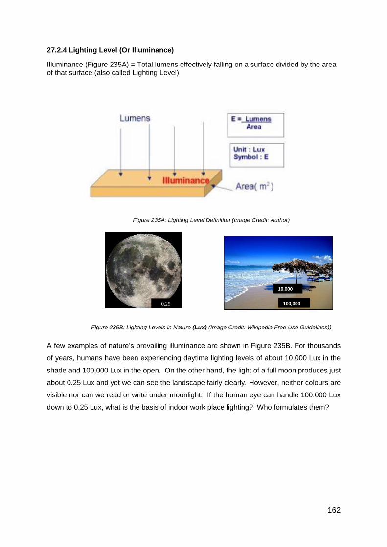
162
27.2.4 Lighting Level (Or Illuminance)
Illuminance (Figure 235A) = Total lumens effectively falling on a surface divided by the area of that surface (also called Lighting Level)
Figure 235A: Lighting Level Definition (Image Credit: Author)
Figure 235B: Lighting Levels in Nature (Lux) (Image Credit: Wikipedia Free Use Guidelines))
A few examples of nature’s prevailing illuminance are shown in Figure 235B. For thousands
of years, humans have been experiencing daytime lighting levels of about 10,000 Lux in the
shade and 100,000 Lux in the open. On the other hand, the light of a full moon produces just
about 0.25 Lux and yet we can see the landscape fairly clearly. However, neither colours are
visible nor can we read or write under moonlight. If the human eye can handle 100,000 Lux
down to 0.25 Lux, what is the basis of indoor work place lighting? Who formulates them?
100,000 Lux
10,000 Lux
0.25

163
27.3 Basis of Singapore Standard Lighting Recommendations
27.3.1 Ophthalmologic Investigations
Figure 236: Age Vs Lighting Level
(Image Credit: Federal Highway Handbook 2012 Free Use Guidelines)
Like many other biological functions like hearing, walking, talking or comprehending, our ability
to ‘see’ things will also get impaired as we grow old. So the lighting requirement of a 40-year-
old worker in an office will be much higher than a younger worker of 20. This ophthalmologic
research finding is shown in Figure 236. Because the retirement age in many countries is
expected to increase beyond 60 years, it is possible that the average working illuminance in
future may have to be raised further. At the same time, there is a limit to the lighting level that
we can provide due to energy considerations.
27.3.2 Lighting-Productivity-Errors And Eye Fatigue
Research on the impact of lighting on productivity and errors, etc. has been ongoing in different
forms by the Illuminating Engineering Societies of Europe and USA as well as the International
Commission on Lighting (CIE in French). This continued research has been on how the
human eye works, how we see, and what role lighting plays with respect to productivity, safety,
errors and visual comfort. A summary of these research findings were published by Dr. Dietrich
Fischer (in Philips International Lighting Review 1985 /Vol 2). In these investigations, productivity
(Figure 237) was found to be highest under 10,000 Lux. That is the same as noon time-illuminance
under the shade of a tree. Such a high level is obviously impossible to realise in an office or
industry. Progressive reduction of illuminance to 2,000 Lux, 1,000 Lux and 500 Lux (in the
experiments) still showed no great fall in productivity up to 500 Lux. But, going below 500 resulted
in a steep drop in productivity.

164
Figure 237: Lighting and Productivity
Errors were likewise minimum under 10,000 Lux but gradually increased as the
illuminance decreased to 500 Lux. Below this level, errors (rejects and accidents)
increased exponentially (Figure 238)
Figure 238: Lighting and Errors
500 2000
500 2000

165
Fig 9. Lighting and Eye Fatigue
Figure 239: Lighting And Eye Fatigue
(Figure237, 238, 239 Image Credit: Philips International Lighting Review Vol 2 1985)
Eye-Fatigue likewise (Figure 239), increased drastically when the average illuminance
decreased below 500 Lux. So there are consistent indicators to the desirability of having 500
Lux in working interiors. This is the basis for SS 531-1 (Lighting of indoor work places) to
specify 500 Lux for many applications (see Table 11)
Table 11: Lighting Levels Specified In SS 531-1:2013
Interior Application area Lighting
level (Lux)
1. Filing, Copying 300
2. Reading, Writing, Data
processing
500
3. Technical Drawings 750
4. CAD work stations 500
5. Conference and Meeting
rooms
500
6. Reception desk 300
7. Archives 200
500 2000

166
27.4 Colour Temperature And Colour Rendering Index
27.4.1 Correlated Colour Temperature (CCT)
The CCT of a light source has important applications for lighting of indoor and outdoor work
places, videography and photography. Colour temperature is conventionally stated in the unit
of Absolute temperature (Kelvin), with symbol K.
An easy way to understand Colour temperature is to look at the gas-flame in a gas cooker
(Figure 240). The blue flame is obviously hotter than the yellow flame of match stick. But blue
is a ‘cool’ colour and so we can draw an analogy that if a lamp looks blue or bluish white, its
“Correlated Colour Temperature’ will be high. For the same reason, a yellow light (like Sodium)
has low Colour temperature because it resembles the less hot yellow flame.
Figure 240: Correlation Of Colour Temperatures (Image Credit: Author)
The ‘Colour Temperature’ of light is not the actual temperature of the lamp. The standard
incandescent lamp and the Halogen lamp are thermal radiators and so their colour
temperature is also their filament temperature. All other light sources like fluorescent lamp or
LED (light emitting diodes) give out light primarily by processes other than thermal radiation.
Their light output is in bands rather than continuous. It means that the emitted radiation does
not follow the form of a black-body as it is heated up. These sources are assigned what is
known as Correlated Colour Temperature (CCT). CCT is the colour temperature of a
corresponding black-body radiator which most closely matches the light from that lamp.
In the morning as the sun crosses the sky from the horizon, it first appears to be reddish and
the sky gradually changes to blue at noon. This mid-day sky corresponds to a black body with
colour temperature of 6000 K. So a fluorescent tube that gives bluish-white light is called
‘Daylight’ tube. Figure 241 shows two impressions of ‘Cool or ‘Warm’ interiors that have the
same ‘physical temperature’ otherwise!

167
Figure 241 Illustration Of Colour Temperatures In An Interior (Image Credit: Philips Lighting)
In Figure 242 is an illustration of Colour Temperatures in nature
Figure 242: Colour Temperatures In Nature (Image Credit: Philips Lighting)
10 000 K
2000 K
6000 K
5000 K

168
SS 531-1 shows a division of three groups according to their CCT (Table 12).
Table 12: Colour Temperature Groups.
Colour appearance Correlated colour temperature
warm below 3300 K
intermediate 3300 K to 5300 K
cool above 5300 K
The choice of colour appearance is a matter of psychology, aesthetics and what is considered
to be natural by the user or owner of a premises. The choice depends on illuminance, colours
of the room and furniture, dominant external climate, etc. In warm climates, generally a cooler
light colour appearance is preferred, and in cold climates a warmer light colour appearance is
preferred. This is borne out by the fact that until now, fluorescent tubes of 6000K were hardly
ever marketed in Europe while Asians hardly bought any tubes below 4000K for homes or
offices. Different manufacturers used to call the same CCT by fancy-names such as ‘warm’,
warm white’, ‘white’, ‘cool white’ that are confusing. The present practice in professional
lighting is to specify lamp colour in Kelvin.
27.4.2 Colour Rendering Index (CRI)
A simple definition of Colour Rendering Index is - it is a measure of the ability of a light source
to accurately render all colours of an object or scene so that there is true colour perception.
This is very important for ‘Visual Satisfaction’ of users. CRI is rated on a scale from 1-100.
The lower the CRI rating, the less accurately colours will be reproduced. Of all the light
sources, only the Sun, and incandescent and Halogen lamps have a CRI of 100 because they
are thermal emitters with a continuous spectrum with all the colours present them (Figure 243).
Figure 243: Full Spectrum Of An Incandescent / Halogen Lamp With CRI=100
(Image Credit: neonlighting.com)

169
SS 531 stipulates that for most of working interiors (Commercial and Industrial), the CRI
should be more than 80. It is because 80 is the threshold at which our eyes can discern colours
reasonably well. Occupants should have visual satisfaction of their own skin tone, objects,
ladies’ cosmetics and surrounds. Figure 244 illustrates the effect of different CRIs on the
same bunch of flowers.
Figure. 244. Different CRI At Same Lighting Level
(Image Credit: Philips Lighting)
27.5 Essentials Of Visual Perception And Visual Comfort
27.5.1 Important Elements
Apart from illuminance, there has to be restriction on Glare as it will produce discomfort to make
things less visible in spite of proper lighting levels. Also, the colours of objects, humans and
surroundings should come out reasonably well to produce visual satisfaction. So the following
criteria are important for indoor lighting.
Illuminance (in Lux)
Discomfort glare (Numerical rating)
Colour Rendering Index (Numerical rating)
There are other criteria which are less critical but nevertheless that contribute to visual
perception and satisfaction. They are:
Colour Temperature
Brightness or luminance in the field of view
Directionality and shadows
The above criteria, together with the aesthetics of an installation, define what is loosely termed
as the ‘lighting quality’. It is important that these criteria should not be seen in isolation but
more as inter-dependent factors.

170
27.6 Measurement Method And Worked Example
27.6.1 Measurement Method And Grid
The lighting measurement (for illuminance) is done at a height of 0.85 to 1.0 m above the
working plane. To have a uniform method of calculation, the following formula can be used to
calculate the maximum grid size to measure the average illuminance.
P = 0.2 × 5 log10 (d)
Where:
‘d’ is normally the longer dimension of the calculation area (m). However, if the ratio of the
longer to the shorter side is 2 or more, d becomes the shorter dimension of the area.
‘P’ is the maximum grid cell size (m) when length of area is less than 10m. That will result in
the following grid sizes for a number of example dimensions (Table 13):
Table 13: Measurement Grid For Indoor Illuminance
(Source: EN 12464-1:2014 Lighting Of Work Places Appendix 1)
Length of Area Maximum distance between
Grid points
Minimum no. of
Grid points
0.40 0.15 3
0.60 0.20 3
1.00 0.20 5
2.00 0.30 6
5.00 0.60 8
10.00 1.00 10
15.00 2.00 12
50.00 3.00 17
100.00 5.00 20
27.6.2 Worked Example:
As the principles of indoor lighting design have to be understood first, the worked example to
calculate number of luminaires and their layout to achieve recommended illuminance is moved
to Chapter 28.

171
Chapter 28: Eco-Friendly Lighting Design
Figure 245A: A Modern Office Interior (Image Credit Philips Lighting)
28.1 Singapore Standard SS 531-1:2006
28.1.1 Maintained Lighting Level SS 531-1 is based on an international standard ISO 8995-1: 2003 whose recommendations
cover commercial, industrial and other work places. The right choice of lighting level
(illuminance) is the first important consideration when designing a lighting installation. It is
specified in terms of ‘average illuminance’ and measured on the ‘working plane’ which is taken
at 1.00 meter above the floor-level for offices and industries (Figure 245B). Asia work tables
tend to have a lower height of 0.85m but the lighting design is deemed to make little difference
by taking 1.0 meter for the working plane.
Figure 245B: Measuring Plane For Indoor Work Place Illuminance
(Image Credit: OSH Fact Sheet- Canadian Center For Occupational Health And Safety)
Our visual acuity (or sharpness of vision) is directly dependent upon the illuminance – the
higher it is, smaller are the objects that can be discerned and less is the eye-strain. So lighting
1.0 m
Lux

172
that is suited to the nature of the task being performed improves visual perception for that task.
The choice of lighting level also depends on other factors like:
a. Work duration;
b. Contrast of the task;
c. The risk of making mistakes;
d. Age of the worker; and
e. Amount of daylight present
SS 531 (with Part 1-2 and 3) stipulates what is called the ‘maintained illuminance’ over the
task area or a reference surface which may be horizontal, vertical or inclined. Maintained
illuminance is the depreciated level of lighting taking into consideration the lamp lumen
depreciation, luminaire output depreciation and room surface depreciation (Figure 246). When
the combined impact of these reaches 70% of the initial lighting level, it will signal the
replacement of the lamp or luminaire. That is called ‘maintained illuminance’ which should not
fall below the values given in the code regardless of the age and condition of the installation.
Figure 246: Maintained Lighting Level (Image Credit: Author)
If the visual conditions are poorer than based on normal assumptions, the value of illuminance
may be increased by at least one step on the scale of illuminance. This can happen when:
a. Contrasts are poor in the working area;
b. Work is critical;
c. Errors are costly to rectify; and
d. Accuracy and higher productivity are important

173
28.1.2 Scale Of Illuminance
A factor of approximately 1.5 represents the smallest significant difference in subjective effect
of illuminance. In normal lighting conditions, about 20 lux of horizontal illuminance is required
to just discern features of the human face and is the lowest value taken for the scale of
illuminances. The recommended scale of illuminance is:
20 - 30 - 50 - 75 - 100 - 150 - 200 - 300 - 500 - 750 - 1000 - 1500 - 2000 - 3000 - 5000 lux.
Likewise, the maintained illuminance may be reduced when:
a. Details are of large size or with high contrast; and
b. Task is undertaken for an unusually short time.
As a default, in any area where continuous work is carried out, the maintained illuminance
shall not be less than 200 lux.
28.1.3 Illuminance Of Immediate Surroundings
The illuminance of immediate surroundings shall be related to the illuminance of the task area
and should provide a well-balanced distribution of luminance (brightness) in the field of view.
Rapid spatial changes in illuminance around the task area may lead to visual stress and
discomfort. The maintained illuminance of immediate surrounding areas may be lower than
the task illuminance but shall not be less than the values given in the Table 14.
Table 14: Ratio Of Task To Surrounding Illuminance.
(Source: SS 531-1:2006)
Task illuminance
lux
Illuminance of immediate
surroundings
lux
> 750 500
500 300
300 200
< 200 Same as task illuminance

174
28.1.4 Discomfort Glare And Unified Glare Rating (UGR)
Glare from the lighting system impairs vision and produces discomfort to occupants in working
interiors. An empirical formula is used to determine Glare. Because there are many occupants
in a working interior, their directions of view and luminaire-brightness that comes into their
view, cannot be controlled. That will again vary due to the constant multi-directional viewing
of occupants. Also glare is a ‘subjective’ feeling. So UGR cannot be physically measured. It
can only be derived from software programs like Dialux that take into account the above
factors automatically while computing Glare.
In the Formula above, the number 8 gives a multiplying factor to get a UGR range of 10-40.
The Log function is because our eye has a logarithmic way of registering brightness.
The Summation sign is to take into account all the luminaires in the field of view of an occupant.
L is the luminance of the luminaire
The sign Omega is the angle between the line of sight of occupant and the luminaire
p is the so-called Guth index and it is based on the distance of a group of luminaires from the
observer. P being in the denominator of above equation, it would mean that the further away
a luminaire, the less glare it will produce.
Lb is the background luminance in Cd/m2, while L is the luminance of an individual luminaire.
Looking at L (which gets squared) and Lb that is linear, it is clear that glare increases for those
lamps with high luminance (like LED) at normal ceiling heights. With more diffused sources
like fluorescent, UGR tends to be less. That is one of the reasons LED luminaires are
equipped with prismatic or opal diffusors to limit the glare.
Some limits:
UGR < 13: Hardly any glare experienced
UGR < 19: Tolerable for normal office interiors
UGR > 28: High glare tolerated only in non-working areas

175
Figure 247: Contribution To Glare By Luminaires
(Image Credit: OSH Fact Sheet- Canadian Center For Occupational Health And Safety)
Figure 247 shows which rows of luminaires can produce direct discomfort glare at a work
station. Details of the UGR method are given in document CIE 117 - 1995. We have already
seen that factors like frequently-changing viewing directions of occupants, layout of work-
stations as well as office equipment or industrial machines in an interior will affect glare. Glare
is also ‘subjective’ and hence it is not possible to calculate UGR manually. It is done by the
computer using lighting design software and based on various interior parameters, luminaire
optics and layout. For accuracy of result on Glare, the most important parameter is the integrity
of the Photometric characteristics of the luminaire. This is called the Illuminating Engineering
Society ‘IES file’ of a luminaire-Photometrics. The IES file contains digital plot of the light
output and intensities in all the planes surrounding a luminaire.
The UGR value of a lighting installation shall not exceed the value given in SS 531. The values
of UGR limits in clause 5 of the Code are taken from the so-called UGR scale - where each
step in the scale represents one significant change in glare and No.13 represents the least
glare and it increases in steps of 3 as below.
The UGR scale is: 13 - 16 - 19 - 22 - 25 – 28
28.2 Green Mark Guidelines Of BCA Singapore
The Building and Construction Authority (BCA) of Singapore administers the Green Mark
scheme for buildings. It is a rating system to evaluate a building for its environmental impact
and performance. It is endorsed and supported by National Environment Agency and provides
a comprehensive framework for assessing the overall environmental performance of new and

176
existing buildings to promote sustainable design, construction and operation practices in
buildings.
Under the assessment framework for new buildings, developers and design teams are
encouraged to design and construct green, sustainable buildings which can promote energy
savings, water savings, healthier indoor environment as well as the adoption of more extensive
greenery for their projects. For existing buildings, the building owners and operators are
encouraged to meet their sustainable-operation goals and to reduce adverse impacts of their
buildings on the environment and occupant health over the entire building life cycle.
The assessment criteria cover the following key areas: -
Energy Efficiency
Water Efficiency
Environmental Protection
Indoor Environmental Quality
Other Green Features and Innovation
Lighting finds a place under Energy Efficiency and Indoor Environmental Quality, the latter (at
present) preferring the use of Electronic High Frequency ballast for fluorescent luminaires.
The major Green Mark criteria are the lighting power density (in Watts/m2) as per SS 530:2014.
The Green Mark assessment identifies the specific energy-efficient and environment-friendly
features and practices incorporated in the projects. Points are awarded for incorporating
environment-friendly features which are better than normal or approved practice. The total
number of points obtained will provide an indication of the environmental friendliness of the
building design and operation. Depending on the overall assessment and points scoring, the
building will be certified to have met the BCA Green Mark Platinum, Gold Plus, or Gold rating.
Certified Green Mark buildings are required to be re-assessed every three years to maintain
the Green Mark status. Table 15 shows the Points that can be scored for lighting as per BCA’
brochure “Green Mark Non-Residential Buildings NRB:2015 Technical Guide and
Requirements”

177
Table 15: BCA NRB:2015 Green Mark Rating For Lighting
Energy Efficiency Green Mark Points
Non-Residential Building Clause 1-6
Encourage the use of energy efficient
lighting to minimise energy consumption
from lighting usage while maintaining proper
lighting level
Baseline Maximum lighting power budget
stated in SS 530:2014
0.3 point for every percentage improvement
in lighting power budget
Points scored = 0.3 (% improvement)
(including Tenant lighting provision)
(up to 12 points)
(Excluding tenant lighting provision)
(up to 5 points)
28.3 Luminaire Types And Modern Developments
T8-T5 fluorescent luminaires have been the dominant light source for commercial offices and
flatted factories with ceilings up to a maximum of 7 metres in height. Currently, there are
millions of fluorescent luminaires used in Singapore and the ASEAN region. Their replacement
with more modern luminaires (using Light Emitting Diode) calls for understanding of the
existing lighting system and characteristics.
Figure 248 Figure 249 Figure 250 Figure 251
(Image Credit Philips Lighting)
Of these, the bare-tube fluorescent luminaire (Figure 248) is the least expensive. Because of
its basic look and glare, it is limited to usage in corridors, passages, small shops, food courts,
toilets, etc.
Figure 249: This luminaire with a trapezoidal metal reflector directs the tube’s output mainly
downward and a small amount of light upwards. Downward efficiency is higher but glare is still
a problem due to bare lamp.
Figure 250 and 251: These are luminaires with opal (milky) or prismatic diffusor. The diffusor
helps to conceal the lamp from direct view, reduces glare and helps to distribute the light wider.
However, absorption of light in the diffusor could be up to 30% and hence efficiency is not that
good. (In a strange twist of technology, LED indoor luminaires have got to make use of these
diffusors again)

178
The so-called mirror optic fluorescent luminaires (Figure 252) are installed in most Singapore
office interiors.
Figure 252: A Typical Mirror Optic Luminaire
(Image Credit Philips Lighting)
Mirror optic luminaires have a pair of glossy or semi-glossy reflectors surrounding the tube to
provide optic control, beam spread and glare-control at certain viewing angles. The cross-
blades or laminations shield the lamp from direct view along the length of the lamp. Such a
luminaire (with no blockage of light like a diffusor) can direct the light better where needed.
Different mirror louvres are used to provide different beam spreads depending on the interior
and the choice of specifier. (Figures 253-254-255).
Figure 253 Figure 254 Figure 255
Typical Mirror-Optic Fluorescent Luminaires
(Image Credit: Philips Lighting)
LED Luminaires are getting increasingly specified and used for indoor lighting. They do not
use mirror-optics because LED itself has a directional output and mirrors cannot contribute
further. Instead, such luminaires use opal or prismatic diffusors because LED can otherwise
cause glare (Figure 256). Because LED’s efficacy is increasing, the limitation of the diffusor
absorbing some light, will not be a hindrance and may be overcome soon.

179
Figure 256: LED Luminaire With Prismatic Diffusor
(Image Credit: Philips Lighting)
For more than 7-8 meters mounting height, the so-called High Intensity Discharge (HID) lamps
were preferred until now. HID lamp family consists of High Pressure Mercury, Standard Metal
Halide, Ceramic Metal Halide, Sodium and Induction lamps. Typical HID high bay luminaires
are shown in Figure 257 and 258. In the last few years, LED high bay luminaires are also
entering this field. Cost-benefit analysis should be done while making a choice between HID
and LED High bay luminaires. Figure 259 shows a typical LED high bay luminaire.
Figure 257 Figure 258 Figure 259
HID And LED High Bay Luminaires (Image Credit: Philips Lighting)

180
28.4 Uniformity And Glare
28.4.1 Uniformity
Regarding uniformity of lighting, Singapore standard SS 531-1 stipulates the following.
“The uniformity of the illuminance is the ratio of the minimum to average value. The illuminance
shall change gradually. The task area shall be illuminated as uniformly as possible. The
uniformity of the task illuminance shall not be less than 0.7. The uniformity of the illuminance
of the immediate surrounding areas shall be not less than 0.5.
28.4.2 Glare
On glare, SS 531-1 has the following stipulations
“Glare is the visual sensation produced by bright areas within the field of view and may be
experienced either as discomfort glare or disability glare. Glare may also be caused by
reflections in specular surfaces usually known as veiling reflections or reflected glare. It is
important to limit the glare to avoid errors, fatigue and accidents”.
A typical recommendation including Glare (in terms of Unified Glare Rating-UGR) is shown in
Table 16 below.
Table 16: Glare (UGR) Limits By SS 531-1
Clause Application area Maintained lighting
level Lux
UGR CRI
3.1 Filing, Copying 300 19 80
3.2 Writing, Reading
and Data
processing
500 19 80
3.3 Technical
Drawings
750 16 80
3.4 CAD Work
stations
500 19 80
3.6 Reception 300 22 80

181
28.5 Photometric Data, Room Reflectance And Room Index
28.5.1 Photometric Data
What are photometric data of a lamp or luminaire? The total luminous flux of a lamp and how
it manifests in various directions with different intensities are captured in the photometric
data of a lamp or luminaire. The intensities can be upward, downward and sideward and in
infinite number of planes as in Figure 260.
Figure 260: Light Intensity Diagram On Multiple Planes
(Image credit: Philips Lighting)
While the multi-directional output of bulb is in Figure 260, the controlled downward light
intensity of a luminaire is shown in Figure 261.
Figure 261: Downward Light Intensity (In Red)
(Image Credit: Zumtobel Lighting)
These intensity diagrams are plotted using the so-called Gonio Photometer. It is a mechanical
device to support and optionally position the light source (a luminaire or lamp) and a photo-
15
0°
120°
90°
60°
30°
180°
150°
0° 30°
120°
90°
60°

182
sensor which measures luminous intensity at each angle, at a set distance. In this case, the
luminaire is mounted on an automatic turning frame, which rotates the device under test
through two axes. A measurement of luminous intensity is taken at each angle as shown in
further figures.
If it is a rectangular luminaire – Figure 262 (as is often used in office lighting), its light
distribution in two cardinal planes as below will be practical.
Figure 262: Light Intensity Diagram Of A Rectangular Luminaire (Image Credit: Author)
However, to calculate the lighting level that will be produced at several points of the working
plane of an office, it will be too cumbersome to calculate each point manually. So to enable a
lighting design software to use luminaire Photometrics, it is necessary to make the data
electronically transferable.
The Illuminating Engineering Society of North America (IES), created the standard document
LM-63-86, “IES Recommended Standard File Format for Electronic Transfer of Photometric
Data.” This is called the IES file of given luminaire and the most common method used globally
to do lighting design is with software like Dialux.
C0 - C180 plane C90 - C270 plane
C-planes
-angles

183
28.5.2 Room Reflectances
When room surfaces reflect more of the available light, they contribute towards higher
utilisation of the lighting system. Hence for commercial and industrial interiors, light-colour or
pastel colour finishes are suggested to increase the surface reflectance of the Ceiling, Walls,
Working plane and Floor as shown in Figure 263.
Figure 263: Surface Reflectance In A Room
(Image Credit: OSH Fact Sheet- Canadian Center for Occupational Health and Safety)

184
28.5.3 Room Index (with K as abbreviation)
K (the Room Index) is the ratio of the vertical reflecting surfaces of an interior to its horizontal
reflecting surfaces as shown in Figure 264.
Figure 264: Room Dimensions Of An Interior (Image Credit: Author)
K = Length (L) X Width (W)
Hm (L+W)
Where Hm is the height of Luminaire above the Working plane
Floor cavity
Ceiling cavity
Working plane
Ceiling plane hm
Length L
Width W

185
28.6 Utilisation Factor, Maintenance Factor and Spacing-to- Height Ratio
28.6.1 Utilisation Factor
Utilisation factor (UF) is the proportion of the luminous flux emitted by the lamps to what is
utilized to produce the illuminance on the working plane. Factors that affect the value of UF
are:
Room Index (based on room proportions)
Room Reflectances
Photometrics of the luminaire
Room Reflectances and Room Index have been explained earlier. We have to consider the
reflectance of the Ceiling (Rc) (False or hard ceiling), Walls (Rw) and working plane (Rp).
Typical reflectances in a modern office interior are:
Ceiling = 0.70
Wall = 0.50
Working plane = 0.30
Together with the Room Reflectances and Room Index, we can get the Utilisation Factor of a
selected luminaire as in Table 17:
Table 17: Typical Utilisation Factor Table Of A Luminaire (Source: CIE, 1995)
For example, if the room index K is 2.5 and room reflectances are 70/50/30, the UF of the
particular luminaire in this situation will be 0.76.

186
28.6.2 Maintenance Factor (MF)
MF is the overall ratio of the lighting level produced by an installation at a specified time,
compared to the lighting level it produced when it is new. The gradual decline in lighting level
is caused by the following sub-factors:
Lamp lumen maintenance factor (LLMF). This is the ratio of a lamp’s light output after a set
time to its output when the lamp was new. This factor allows for the depreciation of lumen
output with age. For example, in the graph of Figure 265, the lamp lumens will depreciate to
70% of initial output when the lamp reaches 12,500 hours of burning. In this case, LLMF =
0.70
Figure 265: Typical Lamp Lumen Depreciation (Image Credit: Author)
Luminaire maintenance factor (LMF) is the proportion of the light output from a luminaire after
a set time to the initial light output from the luminaire. It is mainly due to the accumulation of
dust and dirt on the luminaire. The factors to consider here are the type of luminaire, indoor
atmospheric conditions and maintenance interval.
Room surface maintenance factor (RSMF) is the proportion of the illuminance provided by a
lighting installation in a room after a set time compared with what occurred when the room
was clean. It takes into account possible dust and dirt that accumulate on room surfaces and
reduce surface reflectance.
Combining the 3 above elements, the Maintenance Factor of a lighting installation is the
product of above three elements:
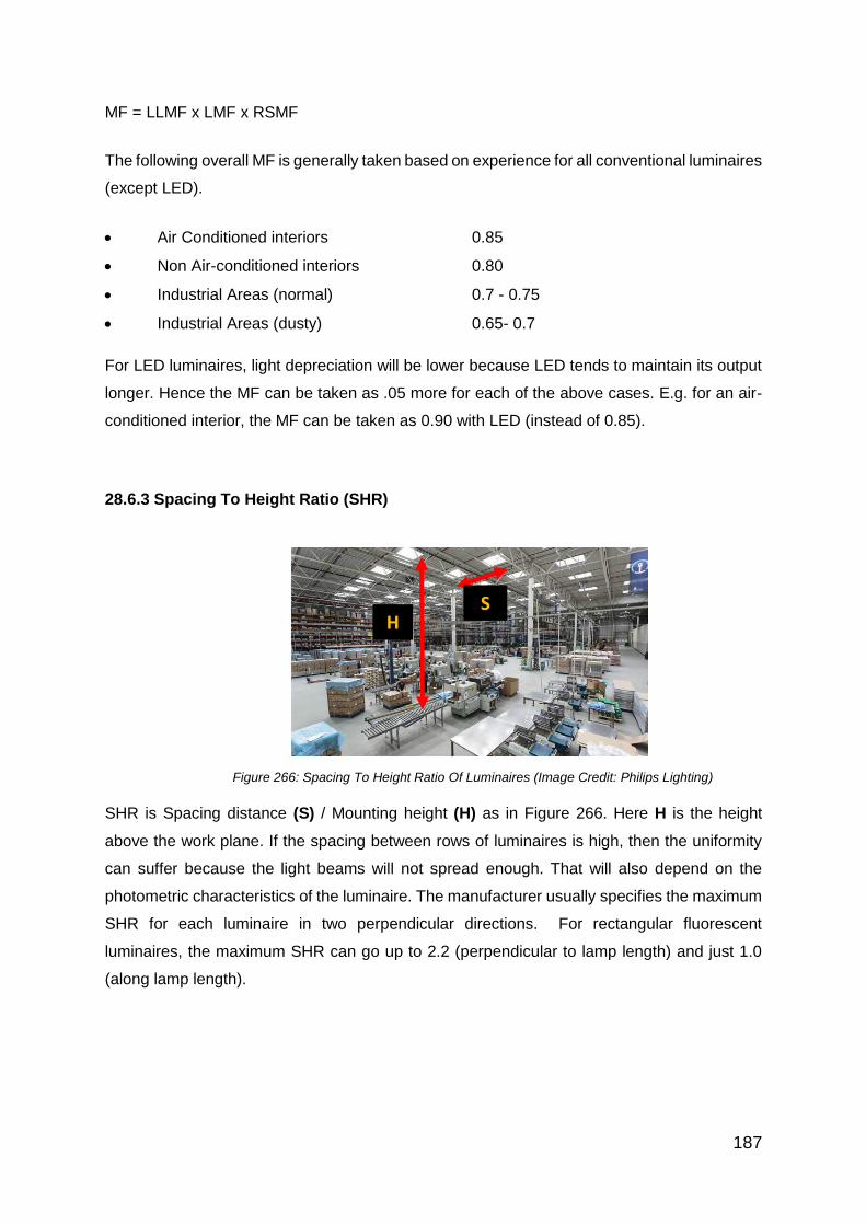
187
MF = LLMF x LMF x RSMF
The following overall MF is generally taken based on experience for all conventional luminaires
(except LED).
Air Conditioned interiors 0.85
Non Air-conditioned interiors 0.80
Industrial Areas (normal) 0.7 - 0.75
Industrial Areas (dusty) 0.65- 0.7
For LED luminaires, light depreciation will be lower because LED tends to maintain its output
longer. Hence the MF can be taken as .05 more for each of the above cases. E.g. for an air-
conditioned interior, the MF can be taken as 0.90 with LED (instead of 0.85).
28.6.3 Spacing To Height Ratio (SHR)
Figure 266: Spacing To Height Ratio Of Luminaires (Image Credit: Philips Lighting)
SHR is Spacing distance (S) / Mounting height (H) as in Figure 266. Here H is the height
above the work plane. If the spacing between rows of luminaires is high, then the uniformity
can suffer because the light beams will not spread enough. That will also depend on the
photometric characteristics of the luminaire. The manufacturer usually specifies the maximum
SHR for each luminaire in two perpendicular directions. For rectangular fluorescent
luminaires, the maximum SHR can go up to 2.2 (perpendicular to lamp length) and just 1.0
(along lamp length).
H
S

188
28.7 Indoor Lighting Design And Calculating Power Density
28.7.1 Design Steps For Indoor Lighting
a. Identify the lighting requirements for the application. This is taken from SS 531-1 for
the specific application. Examples can be seen in Table 1 earlier.
b. Select the lamp type and luminaire. This selection is based on the familiarity and
knowledge of the designer about a specific luminaire, previous experience, in-house
preference for a particular brand, the marketing and sales efforts of the lighting
company, etc. The selected lamps and luminaires will influence lighting level,
Correlated colour temperature, CRI and efficiency of the lighting system.
c. Use the Lumen method of calculation
The lumen method of lighting design is a well-established method. It gives good insight into
what a lighting design software does. It is good for practitioners to know the Lumen method in
order to understand the choices they have while giving inputs to computer programs. A
software called Dialux is freely available to make lighting design easier and elegant. Most
lighting companies seem to support Dialux by providing details of their luminaire range and
IES files to be easily exported to Dialux. The lumen method of lighting design involves a few
easy steps as below:
a. Determine, length, width and height of working space
b. Calculate Room Index (K)
c. Select the reflectance factors of ceiling/wall /working plane
Rc / Rw/ Rp (For offices, 0.7, 0.5, 0.3 are common default values)
d. Look at the Utilisation Factor table of the selected luminaire
e. Choose Utilisation factor (UF) from the Luminaire’s UF table
f. Select Maintenance factor (MF)
g. Calculate no. of luminaires with the formula
N = E x L x W
C x T x UF x MF
Where,
E = Average Illuminance (lux)
L = Length of room in ‘m’
W = Width of Room in ‘m’
C = Light output / lamp (lumens)

189
T = No. of lamps per luminaire
UF = Utilisation Factor
MF = Maintenance Factor
Make a layout of the luminaires
When applied to a square or rectangular interior, the general layout can be as in Figure
267.
Figure 267: Luminaire Spacing Arrangements (Image Credit: Author)
28.7.2 Calculating Power Density (Watts / m2)
a. The first step is to calculate the load (in Watts) per luminaire. That will include (lamp
load + ballast loss per lamp) x the no. of lamps per luminaire. That is the load per
luminaire.
b. The next step is to multiply the above by the no. of luminaires installed.
c. Calculate the area of interior in m2
d. Power Density = Total Watts / m2
28.7.3 Case Study
Kapco Motor Traders Pte Ltd (KMT) is renovating their office with following parameters:
Area = 48m x 20m x 2.8m
Design illuminance = 500 lux
Luminaire = Type ABC with 2 x 36W with Mirror louvre
Lamp = T-8 36W with 2 lamps in each fitting
Maintenance Factor = 0.85
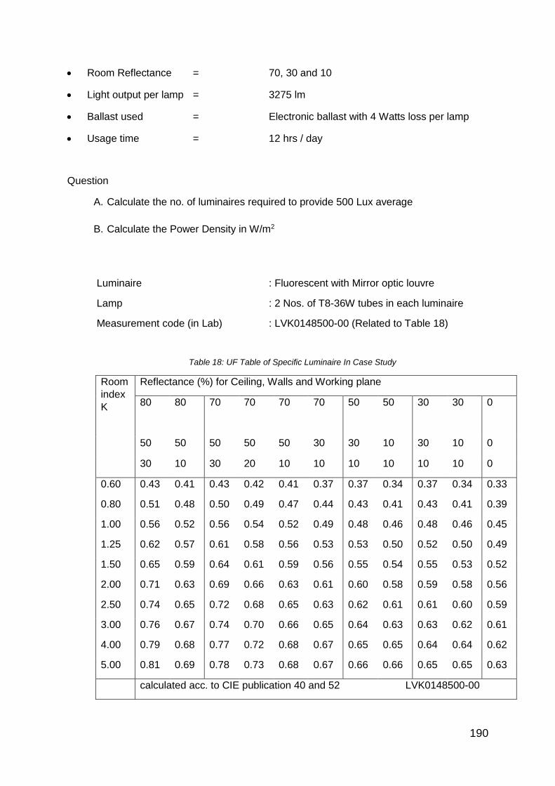
190
Room Reflectance = 70, 30 and 10
Light output per lamp = 3275 lm
Ballast used = Electronic ballast with 4 Watts loss per lamp
Usage time = 12 hrs / day
Question
A. Calculate the no. of luminaires required to provide 500 Lux average
B. Calculate the Power Density in W/m2
Luminaire : Fluorescent with Mirror optic louvre
Lamp : 2 Nos. of T8-36W tubes in each luminaire
Measurement code (in Lab) : LVK0148500-00 (Related to Table 18)
Table 18: UF Table of Specific Luminaire In Case Study
Room
index
K
Reflectance (%) for Ceiling, Walls and Working plane
80 80 70 70 70
70 50 50 30 30 0
50 50 50 50 50 30 30 10 30 10 0
30 10 30 20 10 10 10 10 10 10 0
0.60 0.43 0.41 0.43 0.42 0.41 0.37 0.37 0.34 0.37 0.34 0.33
0.80 0.51 0.48 0.50 0.49 0.47 0.44 0.43 0.41 0.43 0.41 0.39
1.00 0.56 0.52 0.56 0.54 0.52 0.49 0.48 0.46 0.48 0.46 0.45
1.25 0.62 0.57 0.61 0.58 0.56 0.53 0.53 0.50 0.52 0.50 0.49
1.50 0.65 0.59 0.64 0.61 0.59 0.56 0.55 0.54 0.55 0.53 0.52
2.00 0.71 0.63 0.69 0.66 0.63 0.61 0.60 0.58 0.59 0.58 0.56
2.50 0.74 0.65 0.72 0.68 0.65 0.63 0.62 0.61 0.61 0.60 0.59
3.00 0.76 0.67 0.74 0.70 0.66 0.65 0.64 0.63 0.63 0.62 0.61
4.00 0.79 0.68 0.77 0.72 0.68 0.67 0.65 0.65 0.64 0.64 0.62
5.00 0.81 0.69 0.78 0.73 0.68 0.67 0.66 0.66 0.65 0.65 0.63
calculated acc. to CIE publication 40 and 52 LVK0148500-00

191
ANSWER (in steps)
A. No. of Luminaires
Room Index K =
(Length 48m x Width 20m) = 7.8
(Height 2.8m—1) (48+20)
1.When K = 7.8., take the maximum of 5.00 from the UF table
2. From the Table, for K = 5.00 and Room Reflectances of 70-30-10, the UF=0.67
3. Use the formula
N = E x L x W
C x T x UF x MF
48 x 20 x 500
=
3275 x 2 x 0.67 x 0.85
i. Luminaires
1. Power Density
1. A 36W tube dissipates only 32W when operated with an Electronic ballast
2. Load per lamp = 32W (lamp) + 4W (ballast loss) = 36W
3. Load for 125 x Twin-lamp Luminaires = 125 x 36W x 2 = 9.00 kW
4. Area served = 48 x 20 metres
Power density = 9000W / 960 Sq. Meters = 9.40 W/ m2

192
Chapter 29: Characteristics of Lamps-Ballasts And Accessories
29.1 Introduction
Buildings and projects now have a vast choice of lamps and LEDs to suit their applications.
The history of electric lighting has been one of continuous development with major
innovations in the last few decades.
When the incandescent lamp was invented in 1879 by Thomas Alva Edison, its “efficacy* was
just 3 lm/W. That has now improved to about 12 lm/W for commonly used wattages 25-100W.
In 1930s and 40s, the invention and commercialisation of Fluorescent and Gas discharge
lamps offered efficacies around 30 to 35 lm/W. Now they have reached beyond 100 lm/W. In
fact, the T5 fluorescent lamp seems to be still one of the most suitable light sources for interiors
up to 8 Metres in height in terms of Total Cost of Ownership. A fast-progressing innovation in
lighting is the use of Solid State Lighting i.e. Light Emitting Diode (LED). An overall look at the
Lamp family is in Figure 268.
+ LED
Figure 268: The Lamp Family (Image Credit: Author)
Low Pr Sodium
High Pr
Mercury
Standard Incand
Halogen
Gas-Discharge
Lamp Family
Incandescent
Sodium Metal Halide
High Pr Sodium
Fluorescent CFL and Induction
Mercury
Standard and Ceramic
MH

193
29.2 Lamps And Ballast Characteristics
29.2.1 Incandescent Lamp
Figure 269: Typical Incandescent Lamps
(Image Credit: Philips Lighting)
In a typical incandescent lamp (Figure 269), an electric current passes through a tungsten
filament which is a high-resistance wire and heats it to incandescence (= light emitted
through heat). To prevent oxidation of the filament, the bulb contains some inert gases like
Argon and Nitrogen. Over time, the evaporation of tungsten from the filament blackens the
inside of the bulb and depletes the filament until it eventually breaks at its thinnest point. So
the life of the incandescent bulb is just about 1,000 hours. Because of its low efficacy, this
lamp is gradually being banned in many countries including Singapore (from mid-2015). Still
this family of lamps is expected to be used for a long time in future by many under-electrified
countries of Asia, Africa, and Latin America because of its affordability, ability to glow at any
low voltage and freedom from accessories like ballast, starter, capacitor etc.
29.2.2. Halogen Lamp
The halogen lamp family (Figure 270) is also incandescent lamp with a tiny filament. To
minimise its evaporation, some ‘halogen’ compounds are introduced in a quartz or hard-glass
bulb. This lamp comes in a few shapes and wattages to suit different applications, mainly in
social (and non-working) areas and car headlights. Its efficacy is about 25 lm/W but it is still
deemed as an energy-guzzler and a source that heats up the interior.
Figure 270: The Halogen Lamp Family
(Image credit: Philips Lighting)

194
The spectrum of both incandescent bulb and halogen lamp contains all wavelengths of the
visible spectrum (from violet to red) as shown in Figure 271.
Figure 271: The Rich Spectrum Of Halogen Lamp Used Mainly In Shop Lighting
(Image Credit: Philips Lighting)
Because of this rich spectrum, these lamps are deemed to have the highest Colour Rendering
Index of 100. Especially it is more popular in lighting up shops and shopping centres, hotels,
homes, restaurants, etc because of its CRI and the sparkling light appearance. With the small
size of its filament and easy optical control of light beam, the halogen lamp is also a preferred
light source for car head-lights.
29.2.3 Energy Saving Alternatives
Both the standard bulb and Halogen are thermal emitters of light and hence not so energy-
efficient. They add to the air-conditioning load to cool the interior. While the incandescent bulb
is getting banned in Singapore and some other countries, Halogen lamps are very much in
use. There are energy-saving alternatives to Halogen lamps such as Compact Fluorescent
Lamp, Ceramic Metal Halide Lamp and Light Emitting Diode. These lamps are covered later.

195
29.2.4 T8-T5 Fluorescent Tubes
Figure 272: The Fluorescent Lamp Family
(Image Credit: Philips Lighting)
The Fluorescent lamps (Figure 272) come in 3 diameters. The oldest is T12 (1.5” diameter).
Though it is not so energy-efficient, it is used in many developing countries because of its
ability to start at low voltage at night. The T8 (1.0” diameter) provides the same output as 40W
but with 10% less power. T5 is the most efficient in this family. But its diameter is lower (5/8”)
and its length shorter than the T12-T8 tubes. It is highly recommended to avoid the use of T5-
Adapter tubes or LED tubes in an old luminaire that is pre-wired for T8 tube. That is because
the reflector of the old luminaire was designed for T8’s bigger diameter that does not suit T5.
The old accessories (like magnetic or electronic ballast, starter, capacitor, etc for T8) will still
remain inside the fitting. Hence, there is a possibility that those existing accessories may get
in series with the built-in driver of a LED tube. The result could be overheating or short-circuit
of some of the components that could cause fire hazard or electrical faults.
A fluorescent tube is basically a low pressure mercury vapour Lamp with a small dose of noble
gases like Argon and Krypton (Figure 273). Initially, free accelerated electrons from the heated
electrodes tend to excite the noble gas and then the mercury atoms via impact ionisation. This
creates UV emission which is converted by the fluorescent powder to visible light.
T12 – 32 mm dia 40W – 1.24 M long
T8 – 26 mm dia 36W – 1.24 M long
lamp
T5 – 16 mm dia 28W – 1.16 M long

196
Figure 273: The Fluorescent Lamp Operation
(Image Credit: Philips Lighting)
The composition of the fluorescent powder determines the desired light spectrum and colour
temperature. The tubes that are preferred for offices and industries are the ‘Tri-Phosphor’ type
that give out 30% more light than the common Daylight tube. The latter has also a lower Colour
Rendering Index of 70 and hence not recommended for working interiors as per SS 531-1.
Figure 274 shows the fluorescent lamp spectrum of 4000K and CRI of 85.
Figure 274: Spectrum of Daylight Tube
(Image Credit: Philips Lighting)
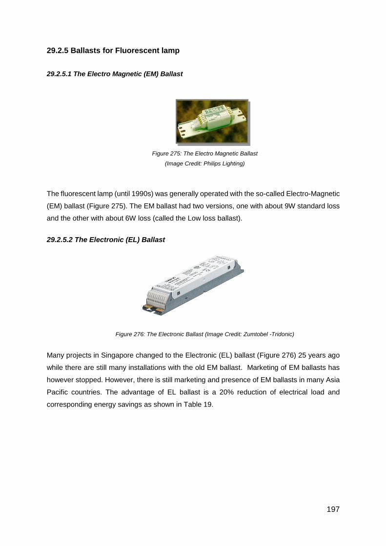
197
29.2.5 Ballasts for Fluorescent lamp
29.2.5.1 The Electro Magnetic (EM) Ballast
Figure 275: The Electro Magnetic Ballast
(Image Credit: Philips Lighting)
The fluorescent lamp (until 1990s) was generally operated with the so-called Electro-Magnetic
(EM) ballast (Figure 275). The EM ballast had two versions, one with about 9W standard loss
and the other with about 6W loss (called the Low loss ballast).
29.2.5.2 The Electronic (EL) Ballast
Figure 276: The Electronic Ballast (Image Credit: Zumtobel -Tridonic)
Many projects in Singapore changed to the Electronic (EL) ballast (Figure 276) 25 years ago
while there are still many installations with the old EM ballast. Marketing of EM ballasts has
however stopped. However, there is still marketing and presence of EM ballasts in many Asia
Pacific countries. The advantage of EL ballast is a 20% reduction of electrical load and
corresponding energy savings as shown in Table 19.

198
Table 19: Energy Saving Due To EL Ballast
Same
Lamp
Ballast
Type
Lamp
Watts*
Ballast
loss
Total
Watts/lamp
T8-36W EM 36W 9W 45W
T8-36W EL 32W* 4W 36W
Note*: The T8-36W tube when operated with the EL ballast will dissipate only 32W in the tube.
With a ballast loss of 4W, the total input-power per lamp will be 36W.
So the load-reduction with an EL ballast in a twin tube fitting will be 18W (= 2 x 9W). Besides,
the EL ballast provides more visual comfort due to avoidance of the so-called stroboscopic
effect that is possible at 50 Hz. The EL ballast is also cooler in temperature and enables longer
life of the fluorescent lamp due to less stress on the lamp electrodes.
29.2.6 Compact Fluorescent Lamp
This miniaturized fluorescent lamp (called Compact Fluorescent Lamp or CFL Figure 277)
became commercially available from the eighties. They are now extensively used in homes,
commercial centres, hotels, restaurants, public housing, etc because of its compact size and
higher efficacy at about 55 lm/W compared to incandescent’s 12 lm/W. The latter comes in 2
versions i.e. “Integrated” (with the ballast inside) and Non-Integrated (with ballast outside in
the luminaire)
Figure 277: Compact Fluorescent Lamp (Image Credit Philips Lighting)

199
29.2.7 High Pressure Mercury (HPM) Lamp
While the fluorescent tube produces low light intensities and suitable for ceilings up to 8 metres
(for T5), there is another group of lamps with higher intensities suitable for mounting heights
greater than 8 metres. These applications are in high bay industries, warehouse and street
lighting. These lamps are collectively called HID lamps as follows:
Figure 278: High Pressure Mercury (HPM) Lamp
(Image Credit: Philips Lighting)
The HPM lamp (Figure 278) contains mercury vapour in a quartz discharge tube (called a
burner) which is inside a pear-shaped bulb. It emits a large proportion of its energy in bluish-
white light. The inner surface of its pear-shaped bulb is coated with a fluorescent powder that
produces about 10 % additional light from the UV content of the burner. The HPM lamp has
rather low efficacy of about 60 lm/W and hence it is gradually being phased out by the lighting
industry with higher efficacy lamps like LED, Induction, etc.
The HPM spectrum and an application example are in Figure 279
Figure 279: HPM Lamp Spectrum And Typical Application
(Image Credit: Philips Lighting)

200
29.2.8 High Pressure Metal Halide (MH) Lamp
Figure 280: The Metal Halide Lamp (Image Credit: Philips Lighting)
The High Pressure Metal halide simply called as Metal Halide (MH) (Figure 280) is basically
also a Mercury lamp with Quartz tube. But additional ‘Halide’ compounds (i.e. salts of Iodine
and Bromine) are introduced to serve as a catalyst that produces higher light output and better
CRI. This lamp is mainly used for sports lighting like swimming pools, sports stadium, tennis
and basketball courts and also for high bay lighting of some industries. The limitation is the
colour-shift during lamp-life and rather short life of about 8000 hours. (Note: There is another
version of Metal Halide with more refinements to increase its Colour Rendering Index to >90
for colour telecast from professional sports facilities like Olympic stadiums, F-1, World cup
soccer. Its spectrum is as shown in Figure 281.
Figure 281: Spectrum of Sports Lighting MH lamp
(Image Credit: Philips Lighting)
29.2.9 High Pressure Sodium (HPS) Lamp
Figure 282: High Pressure Sodium Lamp (Image Credit: Philips Lighting)
The HPS (High-Pressure Sodium) lamp (Figure 282), gives a very high efficacy of 140 lm/W
due to the nature of sodium and gases inside. But the spectrum is not rich enough that it only
gives predominantly yellow light output and its CRI is low at 25. Because of these reasons,

201
sodium is not preferred for indoor applications but more or less exclusively used in road
lighting (Figure 283).
Figure 283: High Pressure Sodium Spectrum and Road Lighting Application
(Image Credit: Philips Lighting)
29.2.10 Low Pressure Sodium (LPS) Lamp
Figure 284: Low Pressure Sodium Lamp (Image Credit: Philips Lighting)
Low Pressure Sodium (Figure 284) has the highest efficacy of about 200 lm/W in the lighting
industry (higher than LED at this point of time). Despite such high efficacy and energy-saving
possibility, the LPS lamp is not accepted in working or social areas due to its ‘mono-
chromatic’ yellow colour with practically zero Colour Rendering. The only place where it is
still useful is in tunnels (Figure 285) where very high lighting levels are required at the
entrance zone to help adapt the vision of drivers from high daylight illumination outside to the
‘black hole’ nature of the tunnel opening. Here the Colour Rendering is not known to be
critical.
Figure 285: LPS Lamp Mono-Chromatic Spectrum And Tunnel Application
(Image Credit: Philips Lighting)

202
29.2.11 Ceramic Metal Halide (CMH) lamp
Figure 286: Ceramic Metal Halide (CMH) Lamps (Image Credit: Philips Lighting)
The standard Metal Halide lamp uses a ‘Quartz’ tube and Metal Halide vapour. But the
Ceramic Metal Halide (CMH) Figure 286 uses a ‘Ceramic’ tube instead. The discharge of metal
halide in a ceramic tube produces entirely different light spectrum suitable for many indoor
and outdoor applications. The efficacy increases to about 90 lm/W and CRI ranges to 80-90.
So this lamp is preferred for shop and show-window lighting. It is an ideal replacement for
Halogen lamps because of about 4 times more light output/W and much longer life-span. But
the existing Halogen luminaire has to be changed because CMH is a gas-discharge lamp
requiring a ballast, while halogen is incandescent with a step-down transformer. The rich
spectral light distribution of CMH lamp (called “Mastercolor” by one Brand with 4000K Colour
Temperature) is shown in Figure 287. For the past several years, CMH has become one of
the best shop-lighting lamps and energy-saving substitute for Halogen.
Figure 287: The Rich Spectrum Of CMH For Shop Lighting
(Image Credit: Philips Lighting)

203
29.2.12 Common Characteristics Of HID Lamps
From the time of switching, HID lamps can take up to 4 minutes to reach full brightness and
stabilised electrical state as seen in the Figure 288. They also have another limitation. When
there is power interruption and after it is restored quickly, the lamp will not re-strike
immediately but take some time. This can take up to 8 minutes during which there could be
total darkness and safety issues. Hence it is advisable to use a few Halogen, LED or
fluorescent lamps that will re-strike immediately after power restoration.
Figure 288: The Start-Up Characteristics Of HID Lamps (Image Credit: Philips Lighting)
29.3 Electrode-Free Lamps
All the lamps described so far have electrodes at both ends of the discharge tube or burner.
The gradual evaporation of the emission-coating on this electrode signals the end of lamp life.
What, if there is a lamp with no electrodes? Theoretically such a lamp could have decades of
maintenance-free life. There are 3 such light sources:
1. Light Emitting Diode (LED)
2. Induction Lamp (IL)
3. Light Emitting Plasma (LEP) (Not covered in this manual as it is less suitable
for Building interiors)
0
20
40
60
80
100
120
140
160
0 1 2 3 4
%
time (In min)
Ila
Wl Vla
Lm

204
29.3.1 Light Emitting Diode
LED has been an ‘indicator’ lamp in our TV sets and appliances for almost 40 years now. So
the LED technology has been around for a long time without our paying much attention.
Electrical control panels and traffic lights started to make LED more visible. From that position
of ‘indicator’, LED has now become a big time ‘illuminator’ in many applications (Figure 289)
with clear advantages of ‘white’ light, long life, high efficacy, and small size and little
maintenance.
Figure 289: Some Applications Of LED (Image Credit: Philips Lighting)
29.3.2 Principles Of LED Operation
LED’s light generation principle is similar to what happens in a gas discharge lamp except the
discharge happens in a solid state material. Hence LED is also called Solid State Lighting
(SSL). As the name implies, LED is a Diode belonging to the Semi-conductor field. Photon-
emitting p-n junctions are typically based on a mixture of elements like Gallium, Arsenic,
Phosphorous, Indium, and Aluminum. The recent addition of Silicon Carbide and Gallium
Nitride has yielded Blue-emitting diodes. The p and n junction is the meeting point of two
different semiconductor materials (Figure 290).

205
Figure 290: LED Light Generation Method
(Image credit: Wikipedia, The Free Encyclopedia)
When dissimilar semiconductor materials are fused, the flow of current into the junction and
the wavelength of light are determined by the electronic character of each material. Electrons
from the n-type region and holes from the p-type region recombine in the vicinity of the junction
that inhibits current flow and creates heat. So to make the current flow, an external DC voltage
is necessary. This DC voltage is provided by an electronic driver that converts AC to low
voltage DC (usually 12V or 24V). A typical LED cross section is shown in Figure 291.

206
Figure 291: Cross Section of A LED
(Image Credit: Wikipedia, The Free Encyclopedia)
29.3.3. Heat From LED
At the p-n junction, substantial heat is developed and it needs to be conducted away through
a heat sink (as shown below) or other dissipation methods. So heat sinks with cooling fins
(Figure 292) are common features of many LED luminaires and lamps.
Figure 292: Cooling Fins On LED Luminaire Ad Lamps
(Image Credit: Philips Lighting)

207
The heatsink is important part of LED luminaires because it can affect both light output and
lifespan.
29.3.4 Making White Light From LED
By nature, LED generates monochromatic light. To create white light, two or more colours
need to be combined. One solution is to mix the output of LEDs in Red, Green and Blue
(RGB colours) in a single window and get white light. This is as per the well-known Physics
principle of adding Red, Green and Blue to produce White light as in Figure 293.
Figure 293: RGB Producing White Light Figure 294: Blue LED With Yellow Phosphor
(Image Credit: Philips Lighting)
Another and more common approach is to use LED that emits blue light and coat it with
yellow phosphor that converts part of the blue to yellow light (Figure 294). In the additive
colour-mixing process, Blue + Yellow = White. If the yellow coating is less, the LED looks
bluer (like 6000K). If the yellow coating is more, then it looks more yellow (like 3000K). By
applying multiple phosphor coatings, blue light can be converted into more colours to
improve the CRI to a level of >80 recommended for working interiors and shop lighting. But
heat-resisting phosphor can be expensive. So a bluish white (6000K) LED will cost less than
a white (4000K) LED because of additional phosphor layer for the latter. For the same
reason, the light output of blue LED is higher than white LED as the phosphor tends to
absorb part of the light.
29.3.5 LED Efficacy (Lumens/W)
Right now, the LED industry claims an operational efficacy of about 140 lm/Watt. This is the
so-called ‘performance efficacy’ delivered after taking care of heat dissipation in the total
system. Further increase is predicted in the coming years taking LED to unique high levels.
The nearest established competitor to LED in office lighting is T5 Tube and for street lighting,
the HPS lamp both having >100 Lumens/W and lifespans exceeding 20,000 hrs. Just for this
group of applications, a comparison of Sodium and T5 with LED and Induction are in Table
20. The Induction lamp is described further on.

208
Table 20: Comparison Of High Efficacy Lamps
Lamp Efficacy
Lumens/
W
Life
time
Hrs
CRI Applications and Remarks
Induction 85 50,000 80-90 Industries, Warehouses and Street
lighting. No temperature issues and hence
known to be durable where maintenance-
freedom is important.
T5 104 20,000 >80 Offices, industries and supermarkets. Well-
established and trouble-free product
HPS 140 24,000 25 Street lighting. Well-established, most
common and durable product
LED 140 50,000 70-90 Offices, industries, Supermarkets, shops,
Streets, Tunnels, etc. 140 lm/W is the
‘delivered efficacy” under practical
conditions.
It can be seen that T5 and Sodium are still good competitors of LED in similar applications
but the former are at lower cost. This may change more in favour of LED in the coming years
due to fast technological improvements by many brands, the huge installed manufacturing
capacities and decreasing prices.
29.3.6 Induction Lamp
The induction lamp is a well-established technology which features reasonably good efficiency
and very long life. It creates light by using high-frequency (>250 KHz) in an electromagnetic
field to excite mercury atoms (Figure 295). The ionized mercury creates UV radiation which is
converted to visible light via a fluorescent coating.

209
Figure 295: Principle Of Induction Lamp
(Image Credit: Philips Lighting)
The difference of Induction lamp is – there is no electrode and hence theoretically this lamp
can last longer than any known lamp. However, the High Frequency generator (at >250 KHz)
in Figure 296 is like any other electronic ballast with a lifespan of 50K-60K hours (about 15
years in an office or industry use).
Figure 296: Electronic Ballast Of Induction Lamp
(Image Credit: Philips Lighting)
Induction lamps use a small dose of mercury amalgam i.e. mercury combined with other
metals. This amalgam is in a chemically stable state, more like a solid paste and not harmful
in the way pure mercury is. It can be recovered at the end of lamp-life more safely than pure
mercury which is in liquid form and more difficult to gather without spillage.
29.4 Comparison Of Different Lamps For Same Interior
A comparison of the characteristics of lamps used from similar heights are shown in Table 21.
Ballast
Discharge Bulb
Power Coupler
Fluorescent powder
I
UV
Visible light
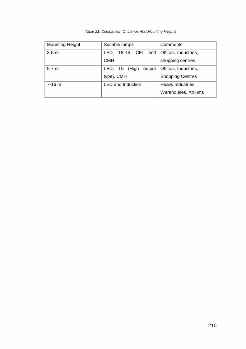
210
Table 21: Comparison Of Lamps And Mounting Heights
Mounting Height Suitable lamps Comments
3-5 m LED, T8-T5, CFL and
CMH
Offices, Industries,
shopping centres
5-7 m LED, T5 (High output
type), CMH
Offices, Industries,
Shopping Centres
7-16 m LED and Induction Heavy Industries,
Warehouses, Atriums

211
29.5 Selection Criteria Of Different Lighting Systems
Table 22 shows the selection criteria and the technical boundaries that are relevant to the different lamps and their cost-benefit for the various
light sources.
Table 22: Technical And Application Comparison Of Light Sources In Professional Applications
Technical
Boundary
T8-T5 with
Electronic
ballast
Sodium Metal Halide LED Induction Remarks
1 Life span 20K hrs 24K hrs 8K hrs 50K hrs 60-80K hrs As of now, many LED
systems seem to have
shorter life due to the acute
competition and consequent
quality-compromise. The
technology itself is sound.
2 Colour
Rendering
Index
80-90 25 70 70-90 80-90 Working areas must have
CRI of minimum 80
3 Mercury
content (If it is
Amalgam,
only weight of
pure Mercury
is taken)
10mg 10-50mg 20-60mg Nil 10-15mg

212
4 Photopic
lumens / Watt
90-104 100-140 70 40-140 75-85 Photopic lumen is applicable
during daytime and
generally lighting levels >20
Lux.
5 Time to full
brightness
1-5 Sec 3-5
Minutes
3-5 Minutes 1-5 Sec 10-30 Sec
6 Colour
temperature
range
2700-
6500K
1950K 3500-5400K 2700-
6000K
2000-6000K
7 Flicker No Yes Yes No No
8 Application
areas
Offices
and
industries
up to 8
metres in
height
Roads,
Open
areas
and
tunnels
Mostly for
Sports
(Flicker
control for
professional
applications
necessary
Retail,
Office,
industries,
Roads,
Façades
and
dynamic
effects
Industries and
warehouse with
>10 meters’
height, Roads
and tunnels

213
Chapter 30: Energy Efficiency And Life-Cycle Study
30.1 Factors Affecting Lighting Energy
30.1.1 Ratio Of Lighting Energy Cost To Product Cost
Lighting (together with other building services like air-conditioning or lifts), consumes certain
amount of energy. For an air-conditioned commercial building in the tropical climate, this is
estimated at 20% of the total energy consumption of the building. So every effort must of
course be made to minimise this energy. But the surprising part is – when we do the Total
Cost of Ownership (TCO) / year, the energy-part constitutes a very high percentage of the
TCO in a lighting installation unlike other services. Table 23 shows this.
Table 23: Typical Lamps And Energy Consumption
Lamp
Type
Ballast
loss
Total W Lamp
life
Energy
consumed
in life time
Energy
cost @S$
0.20/kWh
Product
cost
75W bulb Nil 75W 1000 hrs 75 kWh S$ 15.00 S$ 0.80
36W
tube
9W 45W 10,000
hrs
450 kWh S$ 90.00 S$ 3.50
For a product like incandescent bulb, the energy cost is 18.75 times the product price (=15.00
/ 0.80). For a fluorescent tube, it is 90.00 / 3.50 = 25.71 times the product price.
For other services like air-conditioning or lifts, the capital cost of equipment (and annual
depreciation) will form a much bigger part of TCO. But lighting equipment are relatively
inexpensive but its annual energy-consumption is substantial. Hence careful choice of
luminaires (even with higher investment on reputable and dependable brands) can provide
both economy and peace of mind to building professionals.
30.2 High Efficiency Light Sources And Gears
Table 22 of Chapter 29 has covered many light sources for indoor and outdoor use. Of them,
the following are deemed to be high efficiency types with the option to use with electronic
gear (i.e. Ballast or Driver):
a. LED (for Offices, Industries, shops and Commercial premises)
b. T8-T5 (for Offices, Industries, shops and Commercial premises)
c. Ceramic Metal Halide (Shops, shopping centres)

214
30.2.1 LED As Leading Light Source
From an old indicator lamp on our TV sets and appliances, LED has grown to be a highly
useful light source for many applications. The principles, operating characteristics and
applications of LED are listed in Chapter 29. Unlike most other lamps, LED has no mercury
content and hence is a truly sustainable light source. With its low energy requirement, it can
also operate on direct DC supply of solar power. Thus, the advantage of LED can be
summed up as follows:
a. Ultra-long life (>50K hours including the Driver)
b. Low power consumption
c. Low maintenance
d. No moving parts
e. No UV radiation
f. Cool beam of light
g. Digitally controllable
h. Environment-friendly
30.3 Selection Of Luminaires With High Utilisation Factor (UF)
30.3.1 Luminaire Light Distribution
In selecting luminaires with high Utilisation Factor (UF), we have to reckon with the specific
interior and what type of lighting distribution will provide maximum impact suited to that interior.
In other words, simply directing all the available light downwards is not always the solution.

215
The distribution of light from luminaires is broadly classified in Figure 297.
Figure 297: Luminaire Light Distribution Types
(Image Credit: Philips Lighting)
Direct lighting (Figure 298) applies to offices and industries with heights of up to 7-8 metres.
Coupled with walls, ceiling and work surfaces being ‘light or pastel’ colour in finish, it will lead
to high Utilisation Factor. Glare control of the luminaire is important through the use of
appropriate diffusors or mirror-reflectors.
Semi-direct (Figure 299) may give the impression of sending some light upwards and wasting
it thereby decreasing Utilisation Factor. But in high-ceiling interiors like heavy engineering
workshops and warehouses, the throw of all the light downwards may render the ceiling dark
and occupants may get visually tired with the dark contrast of ceiling. To have a sense of well-
being, they ought to know the finite space in which they work. For this, high bay luminaires
often come with slots or gaps on the upper part of the reflector so that some light is deliberately
sent upwards to the ceiling. That provides a view of the ceiling and an assurance that
occupants are not in a ‘tunnel’ like situation. So, achieving the highest Utilisation Factor is not
always the aim in lighting practice. Avoiding severe contrast in the work interior is equally
important to reduce eye-fatigue.
General diffuse lighting (Figure 300) is used where some ‘vertical’ illumination is important to
reveal the walls, pillars and other possible obstructions in basements, in multi-storey car parks,
corridors and passages of public housing apartments. Revealing of the human face from a
distance is important to some extent for reasons of public safety.

216
Figure 298: Direct Lighting (Image Credit: Zumtobel -Tridonic)
Figure 299: Semi-Direct Lighting (Image Credit: Zumtobel -Tridonic)
Figure 300: General Diffuse Lighting
(Image Credit: Zumtobel -Tridonic)
Other light distributions (like Direct-indirect, Semi-indirect and Indirect) are not preferred in
work spaces. They are somewhat wasteful of light but they are important to create ‘impact’ in
social spaces like the Main lobby and Lift lobbies of prestigious hotels, atriums, conference
and exhibition centres etc. Here the finish of the luminaire (like gold-plating and use of use of

217
crystal glass, high-grade plastics, light-diffusing marble, etc) can emphasise the prestige of
the building more)
30.3.2 Reflection Of Room Surfaces
Room Reflectances have been covered under chapter 28. They play a very useful part to give
a higher UF of the installed light. Other than direct light from the system, what is diffused and
reflected back from these surfaces contribute to better utilisation. For working interiors, it is
highly recommended to use ‘light or pastel’ colour finish of the ceiling, walls and work surfaces.
Restaurants, Clubs, theatres, etc are known to use dark colour finish for their interior as their
aim is to create the so-called ‘cozy’ atmosphere and such premises are not governed by SS
531-1 requirements.
30.4 Lamp And Ballast Retro-Fit And Luminaire Upgrades
30.4.1 Lamp Retrofits
There are many situations where the change of an entire lighting system is not affordable or
practical. Also, Luminaires in offices and industries often continue to be used for > 25 years
without renewal, though their life class is about 10 years. In such cases, the changing over to
retrofit lamps that save energy is logical. The following retrofits are common in existing
luminaires:
a. CFL replacing the Incandescent lamp
b. LED bulbs replacing incandescent and Halogen lamps
c. LED tube to replace T8 Fluorescent tube
Most hotels and commercial establishments in Singapore have more or less retrofitted their
incandescent downlights with CFLs. In a typical example, the 11W CFL with 8000 hrs lifespan
replaces a 60W bulb with 1000 hrs lifespan.
Load reduction (60-11) W = 49W
Energy saved in 8000 hrs life (49x8000/1000) = 392 kWh
@S$ 0.20/Unit, the monetary savings (392 x 0.20) = S$ 78.40
Avoidance of 8 incandescent Bulbs @ S$ 0.80 each = S$ 6.40
Total benefit of CFL = S$ 84.80
Price of one CFL = S$ 8.00!

218
Similarly, the economics of LED bulbs and Retro-fit tubes can be calculated. While selecting
the LED Retrofit tube, it should conform to the most recent standard IEC 62776: 2014 (Double-
capped LED Retrofit Lamps). Non-conforming tubes have the potential to create Fire and
Electrical safety incidents.
30.4.2 Ballast Retrofits
In Table 19 (chapter 29), we saw that the load-reduction due to a ‘twin tube’ EL ballast for 4’
lamp is 18W. The extra cost of a twin-lamp EL ballast (over 2 x EM ballasts) can be recovered
in a matter of less than 2 years. However, ballast retrofit is a very cumbersome process in
existing fittings. The old luminaires have to be taken down to a workshop where the EM ballast,
Capacitor, etc have to be taken out and re-wiring done with EL ballast. Luminaires have to be
tested again and transported back to site and installed. During this time, the office or industry
will have many dark areas and constant site work leading to employee discontent and
complaints. So it is more elegant to procure new luminaires with EL ballast or totally new LED
luminaires rather than retrofitting existing luminaires with so many site problems.
30.5 Depreciation, Product Mortality and Maintenance Issues
30.5.1 Lamp Lumen Depreciation, Mortality and Group Replacement
Figure 301: Lamp Depreciation And Mortality Graph (Image Credit: Author)

219
The declared life of a lamp by the manufacturer is the time when 50% of lamps will fail (Figure
301). Obviously, no building can afford to wait till half the lighting has failed. When a lamp
burns out, the maintenance person first ascertains the lamp type (by visiting the site), gets a
replacement lamp from the store, carries a ladder to the site, opens the fixture, replaces the
lamp and then arranges for disposal of the failed lamp. The entire process may well distract
employees in the vicinity. And without close supervision, the tendency is to drop the failed
lamp into the nearest dust bin where they are quickly covered or probably smashed by other
trash, releasing a small dose of mercury.
So, most lamp manufacturers and lighting maintenance firms recommend “Group replacement
of lamps” at some point before they burn out. It greatly reduces labour wasted on spot re-
lamping, reduces workplace disruption and better controls the lamp disposal process.
Group re-lamping is often done by professional contractors who have focus and training in this
field. The other advantages of group replacement are:
a. Reduce inventory of replacement lamp and ballast. Lighting maintenance contractors
maintain their own stock of lamps and ballasts, obviating the need for a customer to
do the same.
b. Recycle lamps: Many facilities seeking LEED points or other green status may wish
to hand this task over to a firm that knows the most economical and acceptable ways
to meet requirements.
c. Secure incentives. Some lamp manufacturers occasionally offer rebates or discounts
for bulk purchase of lamps. Some countries (like USA) offer incentives for reducing
the load demand that is possible when switching to low-power lamps during group
re-lamping.
d. Handle difficult locations. Professionals are better equipped for high bay or
inaccessible situations.
How Often?
With increased lamp life of T8-T5 tubes, re-lamping cycles are spaced 3 to 4 years apart.
The average T5 lamp life is typically 20,000 hours when (by definition) 50 percent of lamps
will have burned out. At 70 percent of that time (about 14,000 hours) and 4,000 hours’ usage
per year, the group replacement time will come to about 3.5 years.
With LED luminaires, it is common to take a 10-year life span as the time when the initial
light output will depreciate to 70% of the initial value and it is called L70 life.
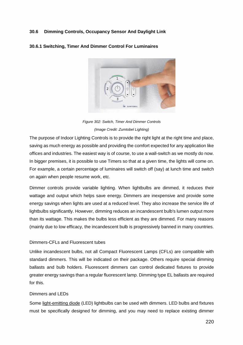
220
30.6 Dimming Controls, Occupancy Sensor And Daylight Link
30.6.1 Switching, Timer And Dimmer Control For Luminaires
Figure 302: Switch, Timer And Dimmer Controls
(Image Credit: Zumtobel Lighting)
The purpose of Indoor Lighting Controls is to provide the right light at the right time and place,
saving as much energy as possible and providing the comfort expected for any application like
offices and industries. The easiest way is of course, to use a wall-switch as we mostly do now.
In bigger premises, it is possible to use Timers so that at a given time, the lights will come on.
For example, a certain percentage of luminaires will switch off (say) at lunch time and switch
on again when people resume work, etc.
Dimmer controls provide variable lighting. When lightbulbs are dimmed, it reduces their
wattage and output which helps save energy. Dimmers are inexpensive and provide some
energy savings when lights are used at a reduced level. They also increase the service life of
lightbulbs significantly. However, dimming reduces an incandescent bulb's lumen output more
than its wattage. This makes the bulbs less efficient as they are dimmed. For many reasons
(mainly due to low efficacy, the incandescent bulb is progressively banned in many countries.
Dimmers-CFLs and Fluorescent tubes
Unlike incandescent bulbs, not all Compact Fluorescent Lamps (CFLs) are compatible with
standard dimmers. This will be indicated on their package. Others require special dimming
ballasts and bulb holders. Fluorescent dimmers can control dedicated fixtures to provide
greater energy savings than a regular fluorescent lamp. Dimming type EL ballasts are required
for this.
Dimmers and LEDs
Some light-emitting diode (LED) lightbulbs can be used with dimmers. LED bulbs and fixtures
must be specifically designed for dimming, and you may need to replace existing dimmer

221
switches with ones that are compatible with LED. The packaging or accompanying instructions
will indicate if the product is dimmable and which dimmers are compatible. Fully compatible
LED dimmers are expected to become more common as the LED industry expands.
30.6.2 Occupancy Sensing
Occupancy sensors work on the principle of sensing the natural heat emitted from humans or
scanning for microwaves due to any interruption by moving objects (i.e. occupants).
Occupancy sensors detect indoor activity within a certain area. They provide convenience by
turning lights on automatically when someone enters a room, and save energy by turning lights
off soon after the last occupant has left the room. Occupancy sensors must be located where
they will detect occupants in all parts of the room.
There are two types of occupancy sensors: Microwaves and Infrared. The former sensor
detects reflected waves (with Doppler Effect), while infrared sensors detect heat given out by
humans. In addition to controlling ambient lighting in a room, they are useful for task lighting
applications such as kitchen counters. In such applications, task lights are turned on by the
motion of a person washing dishes and automatically turn off a few minutes after the person
leaves the area.
Figure 303: Functioning Of The Occupancy Sensor
(Image Credit: Philips Lighting)
30.6.3 Daylight Linking
Lighting (whether natural or artificial) has a big influence on the appearance of a space and
the moods and productivity of its occupants (Chapter 29). Daylighting is the controlled

222
admission of natural light into a space to reduce or eliminate the need for electric lighting. It
offers environmental, economic and social benefits when applied successfully. There is a great
variation between sky conditions in tropical climates like ASEAN and those in Europe and
USA. Most daylighting research is conducted in Europe and daylighting technologies, lighting
calculations and simulations have been developed for those climates. Such welcome
admission of daylight can bring in a lot of solar heat, thereby increasing the Envelope Thermal
Transfer Value (ETTV) of the building. ETTV is the main component for the cooling load of a
building. In general, bright skies and hot climates mean that daylighting cannot be a great
advantage to reduce the electrical lighting load. In order to develop effective daylighting
practices, it is necessary to have a thorough understanding of how particular daylighting
devices will affect a space and its occupants by admitting more solar heat.
Figure 304: Daylight Penetration Through Skylight And Windows Image
Credit:(D/A Magazine By VELUX And Photo Credit To Adam Mørk/ Daniel Blaufuks)
Shading devices and small window openings are employed as the main features of building
design to control excessive penetration of direct sunlight so that heat-gain and glare can be
reduced. Daylighting techniques are explained in the Building Envelope sub-module and not
in the realm of this electric lighting section.
30.7 TCO And Case Study
30.7.1 What Constitutes The Total Cost Of Ownership (TCO)?
The Total Cost of Ownership (TCO) is a financial estimate intended to help buyers and owners
determine the direct and indirect long-term costs of a product or system. It is a management
accounting concept that can be used in full cost accounting or even ecological economics
including social costs.
223
Methods include:
a. Return on investment
b. Time to recover the extra price (Delta) of a chosen system over a cheaper alternative
c. Economic value added by a system
30.7.2 TCO Of Lighting Systems
A Customer’s decision when based only on the initial price of a lighting system, can lead to:
a. Long term high energy expenditure;
b. Frequent lamp replacements; and
c. Defective accessories and maintenance problems; and
d. Poor impression about Facilities Department in the eyes of occupants
Financial Decision-makers often prefer to know the long term cost of owning a system rather
than just the initial investment at the lowest price. They are increasingly calling for the TCO
approach for procurement decisions. Put in a simple way,
TCO = THE ‘ANNUALISED’ COST OF (INVESTMENT + MAINTENANCE).
Generally, a lighting installation is supposed to have a life of 10 years and during this life span,
we can calculate the cost of owning it each year.
Annualized cost of investment = Taken at 10% of the cost of luminaires (on a 10 year life
span).
The initial lamps’ cost is excluded in the investment cost because a lamp is more a
‘consumable’ item and cannot be depreciated over 10 years. So they are taken under annual
maintenance cost as a replaceable item.
Annualized cost of maintenance = Energy cost + Replacement lamp cost + Labour cost
Usually, cleaning charges are not taken into account in most Asian countries because it is
done whenever the lamp is replaced.
Energy cost / yr. = (Load kW x Burning hrs per year) x Tariff charge
per kWh
Lamp cost (Pro-rated for each yr.) =
(No. of lamps x price per lamp x Burning hrs per year)
Lamp life in hours
cleaning charges
224
30.7.3 TCO Worked Example
Question: A factory decides to procure 100 Nos of 2 x 36W fluorescent luminaires with Electro
Magnetic (EM) ballast. A supplier offers the specified luminaire at S$ 80.00 each (excluding
lamps). The vendor has also made an alternative offer for that luminaire but with a twin-lamp
Electronic (EL) ballast. The cost of the latter is S$ 20 more. Given the following data, compare
the TCO of both luminaires
EM Ballast loss for each lamp = 9W
EL Ballast loss for each lamp = 4W
No. of burning hours per year = 4,000 hrs
Electricity tariff = S$ 0.20/kWh
Lamp price (each) = S$ 4.00
Lamp life with EM ballast = 8,000 hrs
Lamp; life with EL ballast = 12,000 hrs
Table 24: Answer To Worked Example
Description Luminaire with
2 x 36W EM
ballasts
Luminaire with
1 x Twin 36W
EL ballast
1 No of luminaires 100 100
2 Price of each luminaire S$ 80.00 S$ 100.00
3 Investment on 100 luminaires S$ 8,000.00 S$ 10,000.00
4 10% Depreciation per year S$ 800.00 S$ 1,000.00
5 2 lamps’ load 2 x 36W=72W 2 x 32W=64W
6 2 EM ballast or 1 Twin EL ballast loss 2 x 9W=18W 2 x 4W=8W
7 Total load per luminaire 90W 72W
8 Load for 100 luminaires 9.0 kW 7.2 kW
9 Energy for 4000 hrs per year 36,000 kWh 28,800 kWh
10 Energy cost @S$ 0.20 per kWh / S$ 7,200.00 S$ 5760.00
11 Lamp life 8,000 hrs 12,000 hrs
12 No. of Pro-rated Lamp replacements
per year
100 67
13 Price of each spare lamp S$ 4.00 S$ 4.00
14 Lamp replacement cost / yr S$ 400.00 S$ 268.00

225
15 Total Cost of Ownership / year (= S/N 4
+ 10 + 14)
S$ 8400.00 S$ 7028.00
16 Annual savings with EL ballast
luminaire (= 8200-7532)
-------- S$ 1372.00
17 Additional investment on EL ballast
luminaire (Row 3 = 10,000 – 8000)
-------- S$ 2000.00
18 Time to recover this additional
investment = 2000 / 1372
--------- 1.45 years!
The 3 elements of TCO (for a luminaire with EM ballast in the above Table), are:
Investment Depreciation cost = $ 800 (9.5%)
Energy cost = $ 7200 (85.7%)
Lamp replacement cost = $ 400 (4.8%)
Total Cost of Ownership = $ 8400 (100%)
From the above, it is clear that energy is the biggest annual expense in a lighting system. Any
additional investment to reduce the electric load can be well-justified and recoverable through
savings within 1-3 years.
30.8 Selection Criteria Of Lighting Systems
When investing in a lighting system, the following criteria should receive attention:
a. Electrical
b. Mechanical
c. Optical
d. Ease of installation and maintenance
30.8.1 Electrical Criteria
The following will come under this:
a. Load (Watts) of the system
b. Power Factor: this has to be >0.85 in Singapore
c. Electro Magnetic Compatibility: Products must conform to IEC 61000-3-2 Immunity
requirements of electrical systems
d. Radio interference

226
30.8.2 Mechanical Criteria
The most important mechanical criteria will be:
a. Adequate strength to withstand the conditions of use for the luminaire and its fixing
arrangements
b. Heat dissipation: Enough mass (by way of casting, cooling fins, etc to dissipate the
heat generated by the light source and driver). This is particularly important for LED
luminaires
c. Ingress Protection (IP) Rating for outdoor applications
30.8.3 Optical Criteria
Here, the criteria will be:
a. Energy efficiency through maximum Downward Light Output Ratio (DLOR) and high
Utilisation Factor
b. Use of reflectors and diffusers to spread the light in an appropriate way to increase
the spacing and thereby reduce the no. of luminaires without affecting uniformity
c. Glare control
30.8.4 Ease Of Installation And Maintenance
The maintenance person will have to access the luminaire at certain intervals to replace the
lamp, trouble-shoot any malfunction and clean its light-contributing surfaces (reflectors, LED
lens etc). So the luminaire should allow easy access to human hands and tools. Diffusors must
be able to hinge open with a retaining mechanism so that the diffusor does not fall down when
the maintenance person is trying to replace the lamp. Ballast, capacitor etc should be
mounted on a gear tray a male-female socket connection so that a defective tray could be
disconnected smoothly at site and replaced with a good gear-tray. The defective one can then
be brought back to the repair-facility and handled. Hardware like screws, clips etc should
preferably be of stainless steel so that they are rust-free and maintenance-free for a long time.

227
30.9 Survey Of Existing Lighting In A Building
In order to survey the existing lighting of a building and its energy performance, a well-
regarded Survey-tool and Template is contained in Technical Report NREL/TP-550-38602 of
October 2005 by the Department of Energy (DOE-USA). Energy managers are well-advised
to use this report for their lighting survey and the model therein for improvement suggestion
and action. (See details under Reference).
30.10 Summing Up
Illumination is obviously an important building service because all our understanding and
impressions in life, work, learning, interactions and success are attributed to good and
comfortable eye-sight. The investment on luminaires in a commercial building is known to be
just about 1.0% of the total cost of construction and furnishing of the building. But lighting’s
impact on productivity, safety and morale is substantial. So it is hoped that the contents of this
sub-module will bring the right perspective on lighting to energy managers.

228
References and Links
1. Daylighting in Buildings: A Sourcebook on Daylighting Systems and Components
2. Building and Construction Authority “Guidelines on Envelope Thermal Transfer
Value for Buildings”
3. Building and Construction Authority “Code on Envelope Thermal Transfer Value
for Buildings”
4. Daylighting guide for buildings. Keith Robertson, Solterre Design
5. "Solar spectrum en" by Nick84 -
http://commons.wikimedia.org/wiki/File:Solar_spectrum_ita.svg. Licensed under
CC BY-SA 3.0 via Commons -
https://commons.wikimedia.org/wiki/File:Solar_spectrum_en.svg#/media/File:Sola
r_spectrum_en.svg
6. BCA Green Mark for NEW Buildings (Non-Residential); 2015
7. SS530: 2014 Code of Practice for Energy Efficiency Standard for Building Services
and Equipment, SPRING Singapore
8. SS531-1: 2006 Code of Practice for Lighting of Work Places (Indoor), SPRING
Singapore
9. LM3-13 IES Guidelines for Upgrading Lighting Systems in Commercial and
Institutional Spaces (Illuminating Engineering Society of North America 2013
edition)
10. IES Lighting Handbook, Tenth Edition (Illuminating Engineering Society of North
America 2011 edition)
11. Susan M. Winchip, Fundamentals of lighting Second Edition 2011(Fairchild Books
US)
12. Philips Lighting Manual, NV Philips Gloeilampenfabriekien, Nederland 2002
13. M.Deru, N. Blair and P. Torcellini. Procedure to measure Indoor Lighting Energy
Performance, Department Of Energy-US document Technical Report NREL/TP-
550-38602, October 2005

229
Suggested Reading Materials (For Lighting)
1. The Physics of Light, Lighting Research Centre, Rensselaer Polytechnic Institute
http://www.lrc.rpi.edu/education/graduateeducation/courses.asp
2. Lamp and control gear
http://www.gelighting.com/LightingWeb/apac/products/technologies/asia-control-
gear/
3. GREEN BUILDING 101: Environmentally Friendly Lighting for Health and Well-
Being http://inhabitat.com/green-building-101-environmentally-friendly-lighting/
4. Lighting Maintenance – Group Relamping (Industrial Lighting and Power)
http://www.industriallightandpower.com/lighting_grouprelamp.php
5. The LEED view: Sustainable lighting
http://www.ecmag.com/section/lighting/leed-view-sustainable-lighting


![GENERAL BUILDING ENVELOPE MECHANICAL SYSTEMS …GENERAL BUILDING ENVELOPE MECHANICAL SYSTEMS LIGHTING & ELECTRICAL POWER OTHER REQUIREMENTS [OR- 1] MANDATORY ADDITIONAL EFFICIENCY](https://img.pdfslide.us/doc/110x75/5f163e1090243225a122eb72/general-building-envelope-mechanical-systems-general-building-envelope-mechanical.jpg)
![BUILDING ENVELOPE MECHANICAL SYSTEMS LIGHTING & … · GENERAL [GE - 1] BUILDING ENVELOPE MECHANICAL SYSTEMS LIGHTING & ELECTRICAL POWER OTHER REQUIREMENTS OVERVIEW What is Supporting](https://img.pdfslide.us/doc/110x75/5fc0606ff6c95c5ddc2b5980/building-envelope-mechanical-systems-lighting-general-ge-1-building-envelope.jpg)


![GENERAL BUILDING ENVELOPE MECHANICAL SYSTEMS LIGHTING ... · GENERAL BUILDING ENVELOPE MECHANICAL SYSTEMS LIGHTING & ELECTRICAL POWER OTHER REQUIREMENTS [OR- 5] PERMANENT CERTIFICATE](https://img.pdfslide.us/doc/110x75/5eae5cd15c8c012170635e4e/general-building-envelope-mechanical-systems-lighting-general-building-envelope.jpg)