Embed Size (px)
Citation preview
The University of Michigan
Building Efficiency Studies
Ann Arbor, Michigan Client Project Number P00017950
Building Efficiency Study Report
PREPARED BY:
SMITHGROUP 500 Griswold Street, Suite 1700
Detroit, Michigan 48226
Project Numbers:11540.000 &12158.000
2020/2021

Copyright © 2021 by the Regents of the University of Michigan
Some rights reserved
This work is licensed under the Creative Commons Attribution-NonCommercial-NoDerivatives
4.0 International License. To view a copy of this license, visit
http://creativecommons.org/licenses/by-nc-nd/4.0/ or send a letter to Creative Commons, PO
Box 1866, Mountain View, California, 94042, USA.
Published in the United States of America by
Michigan Publishing
DOI: http://doi.org/10.3998/mpub.12106747
ISBN 978-1-60785-693-1 (open access)
This publication is a result of work sponsored by the University of Michigan (U-M) President's Commission on Carbon Neutrality (PCCN) to inform the PCCN's final recommendations to U-M President Mark Schlissel. This publication does not reflect Commission-level recommendations, and should not be interpreted as being recommendations of the PCCN nor carrying its endorsement.
The University of Michigan Building Efficiency Studies SmithGroup Ann Arbor, Michigan 12158.000
REPORT - 2 - 2020/2021
CONTENTS
EXECUTIVE SUMMARY ............................................................................................................ 3
PROJECT OVERVIEW..............................................................................................................18 EXISTING FLOOR PLANS............................................................................................................18 PROJECT GOALS.....................................................................................................................20 DATA COLLECTION AND BENCHMARKING .......................................................................................20
EXISTING CONDITIONS & PARALLEL STUDIES ........................................................................21
EXISTING CONDITIONS..............................................................................................................21 TABLE: EXISTING CONDITIONS DISTRICT IMPROVEMENTS ..................................................................22
ANALYSIS ..............................................................................................................................23
INCLUDED IN ANALYSIS .............................................................................................................23 EXCLUDED FROM ANALYSIS .......................................................................................................23 ECM SUMMARY ......................................................................................................................24 DESCRIPTION OF ENERGY CONSERVATION MEASURES .....................................................................25 COMBINED ECMS ...................................................................................................................39 LIFE CYCLE COST ...................................................................................................................41
Art & Architecture Building Energy Efficiency Study
Couzens Residential Hall Building Energy Efficiency StudyEXECUTIVE SUMMARY ............................................................................................................................ . 43
PROJECT OVERVIEW ............................................................................................................................... 74
EXISTING FLOOR PLANS ............................................................................................................................ 74 PROJECT GOALS ....................................................................................................................................... 76 DATA COLLECTION AND BENCHMARKING .................................................................................................... 76
EXISTING CONDITIONS & PARALLEL STUDIES ................................................................................... 77
EXISTING CONDITIONS ............................................................................................................................... 77 TABLE: EXISTING CONDITIONS DISTRICT IMPROVEMENTS ............................................................................ 78
ANALYSIS .................................................................................................................................................. 79
INCLUDED IN ANALYSIS .............................................................................................................................. 79 EXCLUDED FROM ANALYSIS ....................................................................................................................... 79
RESULTS.................................................................................................................................................... 79
ECM SUMMARY ........................................................................................................................................ 81 LIFE CYCLE COST..................................................................................................................................... ..82
The University of Michigan Building Efficiency Study – Art & Architecture SmithGroup Ann Arbor, Michigan 12158.000
REPORT - 3 - 07/20/2020
Executive Summary
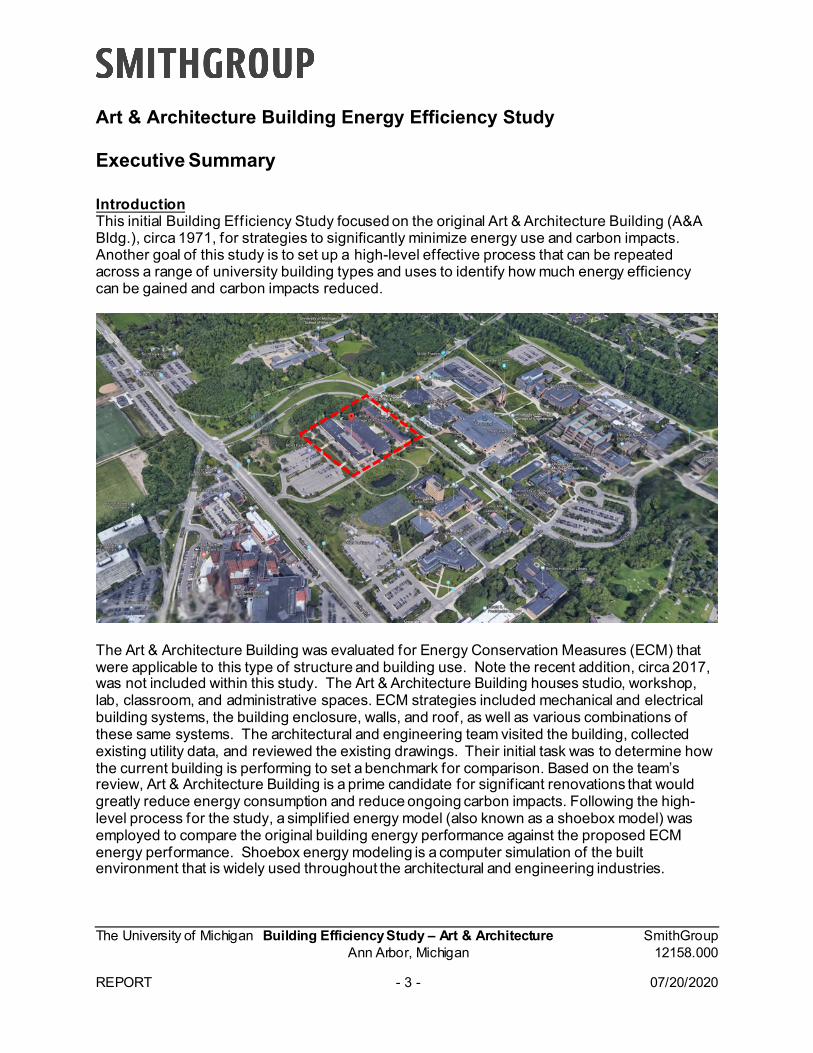
Introduction This initial Building Efficiency Study focused on the original Art & Architecture Building (A&A Bldg.), circa 1971, for strategies to significantly minimize energy use and carbon impacts. Another goal of this study is to set up a high-level effective process that can be repeated across a range of university building types and uses to identify how much energy efficiency can be gained and carbon impacts reduced.
The Art & Architecture Building was evaluated for Energy Conservation Measures (ECM) that were applicable to this type of structure and building use. Note the recent addition, circa 2017, was not included within this study. The Art & Architecture Building houses studio, workshop, lab, classroom, and administrative spaces. ECM strategies included mechanical and electrical building systems, the building enclosure, walls, and roof, as well as various combinations of these same systems. The architectural and engineering team visited the building, collected existing utility data, and reviewed the existing drawings. Their initial task was to determine how the current building is performing to set a benchmark for comparison. Based on the team’s review, Art & Architecture Building is a prime candidate for significant renovations that would greatly reduce energy consumption and reduce ongoing carbon impacts. Following the high-level process for the study, a simplif ied energy model (also known as a shoebox model) was employed to compare the original building energy performance against the proposed ECM energy performance. Shoebox energy modeling is a computer simulation of the built environment that is widely used throughout the architectural and engineering industries.
Art & Architecture Building Energy Efficiency Study
The University of Michigan Building Efficiency Study – Art & Architecture SmithGroup Ann Arbor, Michigan 12158.000 REPORT - 4 - 07/20/2020
Scope The team developed eleven (11) individual ECMs and three (3) combined ECMs. The (11) ECMs include four (4) HVAC (Heating Ventilating Air Conditioning); two (2) electrical and five (5) architectural. Energy and cost were evaluated for each ECM. The following is an overview of each of the ECMs: HVAC Systems ECMs (Heating, Ventilating, Air Conditioning) The current Art and Architecture Building mechanical systems include in-building natural gas-fired steam boilers, Dual-Duct air handling systems, and in-building electric centrifugal chiller cooling. The boilers and air handling systems are considered “high-entropy” systems today, because considerable energy is lost due to heat transfer over high temperature differences (i.e., burning fossil fuel to produce 1,900°F flames to produce 275°F steam to heat spaces to 75°F —when 100°F water would suffice) and moving and mixing disparate air streams (i.e., pushing 100°F Hot Duct air and 55°F Cold Duct air long distances—only to blend them to maintain comfortable temperatures in the occupied areas of the building that today are achievable by other means using far less energy). The primary ways by which new HVAC systems can reduce energy use and carbon impacts compared to the original systems include: using water or environmentally safe refrigerants to move local cooling/heating energy in lieu of high-horsepower fans, reusing the energy in the building to the extent possible for conditioning outside air and for local heating/cooling in lieu of using only “new” energy sources, and relying on a low-entropy campus system to handle the building’s net heating and cooling loads. The four HVAC ECM were developed, exploring the most viable and cost-effective options currently available. Note that all the mechanical ECMs assume that a central campus plant is available to provide heating and cooling water. Costs associated with constructing the central plant are not included since a separate team is studying such plants.
• HVAC-1 DOAS, Chilled Beams o This ECM is to replace the existing building HVAC systems with Dedicated
Outdoor Air Systems (DOAS) for ventilation and Chilled Beams for local cooling and heating.
o Chilled Beams provide zone-based cooling using chilled water (CHW) coils, and it takes less energy to transport cooling capacity via water than in systems using all air like the existing building HVAC system. The CHW used is at relatively high temperature (typically 58°F) which takes less energy to produce than low-temperature (e.g., 44°F) chilled water and can better leverage central plant services.
o For heating, the Chilled Beam coils circulate a relatively low temperature (e.g., 100°F) heating hot water, which is compatible with the central plant being
The University of Michigan Building Efficiency Study – Art & Architecture SmithGroup Ann Arbor, Michigan 12158.000
REPORT - 5 - 07/20/2020
separately studied (anticipating 120°F heating water supply in winter and likely 100°F in summer).
o Chilled Beams use the pressure of primary air distributed from the DOAS unit to induce room air over the CHW coil. This also reduces energy compared to fan-powered systems.
o The use of chilled beams allows code-required, conditioned, reduces 100% outside ventilation air to be provided by a separate DOAS, which reduces the amount of transported air to be moved by central fans. The DOAS unit will judiciously use lower-temperature CHW (i.e., 44°F) from the central plant to dehumidify humid outside air.
o The DOAS also provides better temperature & humidity control, because it can be focused on ventilation air needs and not local heating and cooling needs, and it employs efficient energy wheels to recover in-building energy in lieu of tapping new sources.
o Additionally, this system is easier to fit into the building ceiling space, since much smaller central system ductwork is required.
o Modifications to floor and roof structure to support adjacent work will be required.o Modifications to the existing roof due to adjacent work will be required.o Modifications to the existing ceilings and walls due to adjacent work will be
required.Modifications to the existing fire suppression system due to adjacent work will be required.
• HVAC-2 DOAS, Chilled Boxes & Chilled Beamso This ECM is to replace the existing building HVAC systems with Dedicated
Outdoor Air Systems (DOAS) for ventilation, and Chilled Boxes for the majority oflocal cooling and heating zones but Chilled Beams for small zones.
o The Chilled Boxes provide the same function as the Chilled Beams in ECMHVAC-1, using the same water temperatures. But they are essentially fan-powered boxes, using efficient, variable-speed, Electrically Commutated Motor(ECM) fans to move air over dry (i.e., sensible cooling-only) local cooling coils, inlieu of induction chilled beams utilizing DOAS supply air.
o Chilled Boxes cost less to install for mid- and larger-size zones because theyprovide more cooling per unit vs. chilled beams. Therefore, chilled boxes cover a larger area and less units are required to serve the same area which reduces theoverall installation cost. The Chilled Boxes would be used in the studios andlarge classroom spaces.
o The DOAS unit would be similar to that in ECM HVAC-1, though slightly smaller,since Chilled Beams in large and high-heat-gain zones often require a bit moreDOAS air supply flow to meet room air induction needs than the rooms need forventilation alone, and local fans in Chilled Boxes eliminate that constraint. As
The University of Michigan Building Efficiency Study – Art & Architecture SmithGroup Ann Arbor, Michigan 12158.000 REPORT - 6 - 07/20/2020
such, the savings in DOAS/ventilation energy is greater than what the local fans consume.
o Chilled Boxes require more maintenance because of the local fans and filters employed. Modifications to floor and roof structure to support adjacent work will be required.
o Modifications to the existing roof due to adjacent work will be required. o Modifications to the existing ceilings and walls due to adjacent work will be
required. o Modifications to the existing fire suppression system due to adjacent work will be
required.
• HVAC-3 DOAS, Chilled Sails, and Destratif ication Fans o This ECM is to replace the existing building HVAC systems with Dedicated
Outdoor Air Systems (DOAS) for ventilation, and Chilled Sails with Ceiling Destratif ication Fans for local cooling and heating.
o Chilled Sails plus Destratif ication Fans couple the radiant cooling and heating effects of a standard radiant ceiling panel with enhanced surface area and an enhanced convective heat transfer component for increased performance and higher comfort.
o They are like Chilled Beams in that no local fan is required, no local f ilter is provided, and they are limited in peak cooling capacity.
o The DOAS system would be the same as for HVAC-2 (i.e., smaller than for Chilled Beams), with ventilation air being the sole factor for sizing.
o Significantly, however, ceiling destratification fans allow equal or greater occupant comfort because the temperature of the space can be set higher due to the air movement which provides a cooling effect. This slight increase in space cooling temperature saves considerable energy by allowing cooling equipment to work more efficiently.
o However, chilled sails and destratif ication fans are not always practical to implement for a given space. Further study during design would be needed to determine the extent of implementation possible. Modifications to floor and roof structure to support adjacent work will be required.
o Modifications to the existing roof due to adjacent work will be required. o Modifications to the existing ceilings and walls due to adjacent work will be
required. o Modifications to the existing fire suppression system due to adjacent work will be
required.
The University of Michigan Building Efficiency Study – Art & Architecture SmithGroup Ann Arbor, Michigan 12158.000 REPORT - 7 - 07/20/2020
• HVAC-4 DOAS, with Water-Source Variable Refrigerant Flow (VRF) local heating and cooling
o This ECM is to replace the existing HVAC Building systems with Dedicated Outdoor Air Systems (DOAS) for ventilation, and Variable Refrigerant Flow fan coils for local cooling and heating.
o The local VRF fan coils will be served by centralized, water-source VRF heat pump units that are connected to the central energy plant warm and cool water systems.
o Refrigerant is transported between the heat pumps and a network of indoor fan coils equipped with refrigerant coils. The amount of refrigerant to each fan coil is varied to match the heating and cooling load, which is more efficient than on/off type refrigerant control. Sophisticated controls allow heating and cooling energy to be swapped between separate zones to the location needed.
o This means heating and cooling would be moved between building spaces to the extent possible before excess heating or cooling load must be taken from or added to the central plant systems.
o In this unique application, net heat rejection from the building (i.e., for a net cooling load) will go to the central plant heating hot water return pipe (employing heat pumps’ ability to efficiently move heat in a “high-lift,” or slightly higher-temperature-output mode), thus helping the central plant create a heating resource that other buildings on the central plant system can use year-round.
o Similarly, net heating demand in the building (i.e., for a net heating load), will be extracted from the central plant chilled water return pipe, thus helping the central plant create a cooling resource that other buildings on the central system can use year-round. In effect, this means the central plant warm and cool water systems are only taxed for DOAS loads, while VRF loads are transferred in a way that reduce central plant loads.
o This innovative synergy between building VRF compressors and new central plant energy systems is what boosts this ECM’s carbon reduction to a remarkable 77%, versus the base building. (Note, a “low-lift” HVAC-4A option was also considered without this feature, though it was dropped as less effective.)
o VRF systems are highly engineered systems that use proprietary replacement parts, require more sophisticated maintenance staff, and are less flexible for future architectural modifications.
o However, their energy and carbon reduction advantages are exemplary. o Modifications to floor and roof structure to support adjacent work will be required. o Modifications to the existing roof due to adjacent work will be required. o Modifications to the existing ceilings and walls due to adjacent work will be
required. o Modifications to the existing fire suppression system due to adjacent work will be
required.
The University of Michigan Building Efficiency Study – Art & Architecture SmithGroup Ann Arbor, Michigan 12158.000
REPORT - 8 - 07/20/2020
Electrical Systems ECMs (Electrical)
• ELECT-1 PVo This ECM is to install a roof-mounted Photovoltaic (PV) system of the maximum
practical capacity given the available roof area.o The significant benefit of this is that it utilizes the expansive natural asset of the
building’s flat-roof solar exposure to offset an appreciable portion (close to half) of the renovated building’s remaining electrical power needs.
o It also helps shade the roof from the hot summer sun.o PV capacity could also be pursued through photovoltaic carports or at a central
plant or an off-site scale, parking lots are subject to becoming future building sites, and central plant projects struggle to access building-based solar assets such as large flat roofs.
o Existing roof systems modifications including structural reinforcing will be required to support the added weight and repair roof at installation points.
o Roof tie off protection will be installed to provide permanent safety.o Ceilings will be replaced that are impacted by structural reinforcing.
• ELECT-2 LEDo This ECM is to replace existing light f ixtures with improved fixtures equipped with
LEDs (Light Emitting Diodes).o Energy savings would accrue not only on the basis of slightly higher energy
efficiency at the LED sources (i.e., compared to LED retrofit components in original f ixtures), but in appropriately redesigning the lighting distribution and intensity per current standards and opportunities (i.e., compared to the limitations of the original light f ixture types and spatial distribution).
o New LED systems would also include controls that adjust lighting levels to compensate for daylight and would turn off lights when spaces are unoccupied.
o Modifications to floor and roof structure to support adjacent work will be required.o Modifications to the existing roof due to adjacent work will be required.o Modifications to the existing HVAC and f ire suppression system due to adjacent
work will be required.
The University of Michigan Building Efficiency Study – Art & Architecture SmithGroup Ann Arbor, Michigan 12158.000 REPORT - 9 - 07/20/2020
Arch Systems ECMs (Architecture)
• ARCH-1 New Curtain wall o Replace the existing curtain wall, which meets current energy code performance
requirements, with a more energy efficient system. The existing curtain wall accounts for the majority of windows in the building and is typically large expanses of glass on the building. The existing curtain wall system is a single glazed system which preforms worse. A new modern curtain wall will allow the system to lose less heat to the exterior in the winter and will reduce the amount of heat entering the building in the summer.
o Structure near each window will need to be investigated and modified to allow for the attachment of the new system. This will require selective demolition at each window opening.
o Adjacent systems such as roofing may need to be repaired if they are integrated into the curtain wall system.
o Depending on the placement and proximity of Mechanical, Electrical, and Plumbing, some systems may need to be moved or recalibrated due to the area of construction.
o Interior f inishes near the construction area will likely need to be repaired and cleaned.
• ARCH-2 High Performance Curtain Wall o Replace the existing curtain wall with a system that is better than current code in
performance. As stated in ARCH-1 the existing curtain wall system performs less than a contemporary system. However, for this ECM the curtain wall will be a very high performing system. While ARCH-1 will help reduce the amount of energy to heat and cool the building, this ECM will provide increased energy efficiencies.
o Similar to ARCH-1 interior f inishes, Structural, Mechanical, Electrical, and Plumbing work will be required.
• ARCH-3 High Performance Skylights o Replace the existing skylights with high performance glazing. The existing
skylights run east-west along corridors and studio spaces. They are uninsulated with single pane glass allowing for additional heat loss during the winter, and heat gain in the summer. Contemporary skylights can now utilize insulating glass and insulation can be added to the frame that connects them to the building and provides a much more energy efficient system.
o In addition to the additional impacts listed in ARCH-1, there will be additional roofing work required to maintain air and water tightness where the roof meets the skylight.
The University of Michigan Building Efficiency Study – Art & Architecture SmithGroup Ann Arbor, Michigan 12158.000 REPORT - 10 - 07/20/2020
• ARCH-4 10% Existing Glazing Reduction o Remove 10% of building glazing and infill with a solid energy efficient exterior
wall system. Glass typically allows more heat gain or loss than a contemporary wall system. While on site it was observed that many of the studios had curtains that were closed, potentially due to too much exterior light entering the space. There were also areas where exterior lighting could be reduced due to the activities that were occurring in that space such as kiln rooms. While it is not recommended to eliminate exterior daylight from any one space, an estimated 10% of glass could likely be reduced from around the building. In the areas where the glass would be reduced, an insulated wall system that does not let any light in would fill the space where the glass originally occurred. This insulated wall system could be spandrel glass or wall infill depending on location of the infill and if the ARCH-5 is selected. By adding this insulated portion of wall, the room will become more comfortable to occupants near the wall and will increase the thermal efficiency of that portion of the wall.
o The construction of the infill will impact both interior and exterior construction in order to integrate with the existing construction.
o Main structural elements, Mechanical, Electrical, Plumbing and Roofing, will likely be unaffected as most of the work will be installed in the established opening.
• ARCH-5 Reskin building with new exterior veneer, high performance curtain wall and skylights, and reduce glazing by 10%.
o The existing wall utilizes common construction practices for the time it was built. This means that the insulation value for the existing wall is quite low. Additionally, the existing building does not have a continuous means to limit the amount of exterior air that can enter the building.
o Removing the existing brick that is on the building will allow the installation of an air barrier on the existing building. By reducing the amount of air that can come in and out of the building, the mechanical system can heat and cool spaces more efficiently. Air barriers control reduce the air leakage into and out of the building envelope. . The amount of air leakage has a direct influence on the amount of heat that can bypass the insulation. By reducing the amount of air that can come in and out of the building, the mechanical system can heat and cool spaces more efficiently. Additionally, Air Barriers reduce water infiltration into the building and reduce the risk of condensation in the wither, both functions will help protect the existing structure from long term water damage.
o Removing the brick will also allow new insulation to be installed. Adding new insulation on the exterior of the building will significantly increase the energy efficiency of the exterior wall. This will also make the spaces within the building that are located on an exterior wall more comfortable to the users.
o Because removing the existing brick is a significant undertaking, and will likely impact the curtain wall framing, it is the perfect opportunity to replace the curtain wall with high performance systems and reducing the amount of glazing.
o Replacing the skylights with higher performing glass would also be recommended at this time because it would be the last poor performing system on the building envelope.
The University of Michigan Building Efficiency Study – Art & Architecture SmithGroup Ann Arbor, Michigan 12158.000 REPORT - 11 - 07/20/2020
o This ECM has the potential to have a limited impact to the occupied space within the building during the time of construction. However due to the unknown variables there is a possibility that significant disruption to the occupied space may be required. This level of disruption will not be known until selective demolition of the existing wall has taken place and reviewed by a structural engineer.
o All major systems within the exterior wall will likely be impacted by the ECM including the Structure, Mechanical, Electrical, Plumbing. While not all systems will be impacted the same, the change to the wall is significant, and in field conditions may require the alteration, moving, or recalibrating of these systems.
o In addition to the above grade structural improvements that may be required, there will be structural impacts to the foundation. This will be based on the weight and attachment system of the new exterior wall veneer.
o Roofing and waterproofing will require some modifications to allow the new air and water barrier to integrate with the existing systems. Air and water tightness are critical to the longevity and efficiency of a building, so new systems should be integrated with the existing.
o Due to the extensive construction from the exterior, some site work will be required to remove any damage from the construction.
o This EMC has a lot of unknown variables including the condition of the existing structure and interior part of the existing wall. To capture these unknowns, the following ARCH-5 Alternatives were created. Each address either an aesthetic choice or a structural limitation. ARCH-5 Alt 1 Brick Reskin, High Perf Curtain wall & Skylights, 10%
Glazing Reduction • Remove existing brick exterior and replace with new energy
efficient brick enclosure. o By removing the existing brick installation of a continuous
air barrier will be much easier. This is because the existing inner wall can be cleaned and repaired to increase the chances of a good installation.
o Adding insulation to the existing wall will make the system thicker. By removing the existing brick, this additional thickness will be reduced which will likely be easier for the existing structure to accommodate.
o Installing new brick after the installation of the air barrier and insulation will allow the building to maintain a look that is similar to what it is now and will also increase the thermal performance of the wall assembly.
• Replace existing curtain wall and skylights (See explanation in ARCH-2-3)
• Reduce glazing by 10% (See explanation in ARCH-4) ARCH-5 Alt 2 Rainscreen Reskin, High Perf Curtain wall & Skylights, 10%
Glazing Reduction
The University of Michigan Building Efficiency Study – Art & Architecture SmithGroup Ann Arbor, Michigan 12158.000
REPORT - 12 - 07/20/2020
• Remove existing brick exterior and replace with a rainscreenexterior wall system.
o This Alt is like ALT 1, however removing the brick gives anopportunity for a wall to be replaced with a system that isaesthetically different from brick. This will not change thethermal performance of the new wall assembly but couldchange the visual identity of the building.
• Replace existing curtain wall and skylights (See explanation inARCH-2-3)
• Reduce glazing by 10% (See explanation in ARCH-4) ARCH-5 Alt 3 Metal Panel Over Existing Brick, High Perf Curtain wall &
Skylights, 10% Glazing Reduction• Install insulation and new metal panels over existing brick
exterior.• Instead of removing the existing brick there is a potential that the brick
could be left in place. This will likely reduce the installation schedule.o The additional thickness of the wall, caused by keeping the
existing brick, will push the weight of the rain screen system out further than previous options. Because the weight will be cantilevered out further from the structure, the system will likely need to be constructed of lighter materials. Allowable weight can be calculated after the structure has been fully evaluated.
• Replace existing curtain wall and skylights (See explanation in ARCH-2-3)
• Reduce glazing by 10% (See explanation in ARCH-4)Three scenarios were then developed where various ECMs were combined to maximize energy use reduction and reduce carbon impacts:
The University of Michigan Building Efficiency Study – Art & Architecture SmithGroup Ann Arbor, Michigan 12158.000 REPORT - 13 - 07/20/2020
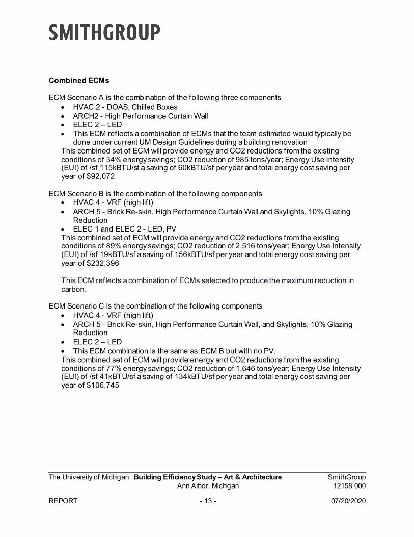
Combined ECMs ECM Scenario A is the combination of the following three components
• HVAC 2 - DOAS, Chilled Boxes • ARCH2 - High Performance Curtain Wall • ELEC 2 – LED • This ECM reflects a combination of ECMs that the team estimated would typically be
done under current UM Design Guidelines during a building renovation This combined set of ECM will provide energy and CO2 reductions from the existing conditions of 34% energy savings; CO2 reduction of 985 tons/year; Energy Use Intensity (EUI) of /sf 115kBTU/sf a saving of 60kBTU/sf per year and total energy cost saving per year of $92,072
ECM Scenario B is the combination of the following components
• HVAC 4 - VRF (high lift) • ARCH 5 - Brick Re-skin, High Performance Curtain Wall and Skylights, 10% Glazing
Reduction • ELEC 1 and ELEC 2 - LED, PV This combined set of ECM will provide energy and CO2 reductions from the existing conditions of 89% energy savings; CO2 reduction of 2,516 tons/year; Energy Use Intensity (EUI) of /sf 19kBTU/sf a saving of 156kBTU/sf per year and total energy cost saving per year of $232,396
This ECM reflects a combination of ECMs selected to produce the maximum reduction in carbon.
ECM Scenario C is the combination of the following components • HVAC 4 - VRF (high lift) • ARCH 5 - Brick Re-skin, High Performance Curtain Wall, and Skylights, 10% Glazing
Reduction • ELEC 2 – LED • This ECM combination is the same as ECM B but with no PV. This combined set of ECM will provide energy and CO2 reductions from the existing conditions of 77% energy savings; CO2 reduction of 1,646 tons/year; Energy Use Intensity (EUI) of /sf 41kBTU/sf a saving of 134kBTU/sf per year and total energy cost saving per year of $106,745
The University of Michigan Building Efficiency Study – Art & Architecture SmithGroup Ann Arbor, Michigan 12158.000 REPORT - 14 - 07/20/2020
Opinion of Probable Costs This study calculates simple payback in years as the difference between the Project Cost divided by the Annual Energy Cost savings. To determine the Project Cost, the team sought to estimate the total cost of the project. In Exhibit 6 – Costs Analysis, the Opinion of Probable Cost (OPC) is an estimate of the construction cost. Construction cost is the amount paid to a contractor (i.e., General Contractor or Construction Manager) to build the project, including the material costs, the labor costs, and the contractor's overhead & profit. Also, because this study seeks to estimate the construction cost for a future project, an allowance was included for material & labor escalation. Given the preliminary nature of this study, a design contingency was included. As noted above, in addition to Construction Cost, there are other expenses that would be necessary to complete any of these potential ECM projects. These additional expenses include things like "Related Construction" (e.g., new/revised utility and City connections, etc.), Owner's contingencies (e.g., Construction Contingency, etc.), professional fees, and miscellaneous expenses. Based on experience with previous projects, the study assumes that other expenses would be 35% of the estimated construction costs. This 1.35 factor included construction contingency, which is why the OPC notes that it contains 0% for construction contingency. The opinion of probable costs may be perceived as high when considering a specific ECM or even a combined ECM. However, the detailed estimate included in the appendix show the extent of construction work that is required for each ECM and the combined ECM scenarios. It should also be noted that the simple paybacks provided here-in assume the existing system(s) do not need to be replaced. This produces long simple paybacks. A comparative example would be replacing your home furnace when not broken solely for the purpose of gaining the benefit of improved energy efficiency. However, during a major renovation, the simple payback would be calculated based upon the cost difference to install a more energy-efficient system verses a system that just meets current energy code requirements, resulting in shorter simple paybacks. The opinion of cost detail includes scope of work beyond just the direct components of the ECM. Other building infrastructure and existing conditions will be affected by the work required to implement the ECM. This includes structural upgrades, roofing repair or replacement, reworking or replacing mechanical, electrical, plumbing components, and replacing interior f inishes. It is also important to highlight what is not included in the project's costs proposed by this study:
• Any improvements beyond those described in the study which does not include improvements to the recent addition completed in 2017.
• Escalation beyond the two years that was included in the estimate. Additional escalation may be appropriate depending on the timeframe for implementation.
• Phasing and/or temporarily other measures to facilitate the continued use and occupancy of the building during construction.
• Any costs to temporally relocate the building occupants, furniture, or equipment.
• Metering and monitoring beyond what is typical for a comparable UM building.
The University of Michigan Building Efficiency Study – Art & Architecture SmithGroup Ann Arbor, Michigan 12158.000 REPORT - 15 - 07/20/2020
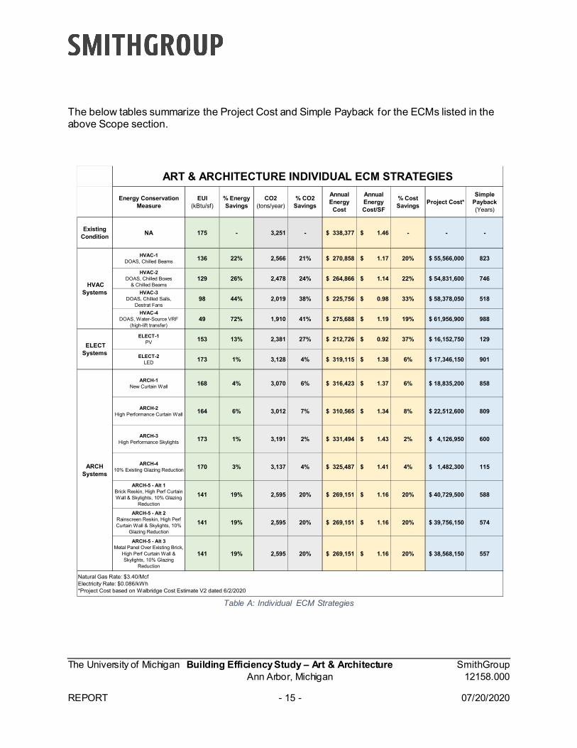
The below tables summarize the Project Cost and Simple Payback for the ECMs listed in the above Scope section.
Table A: Individual ECM Strategies
Energy Conservation Measure
EUI (kBtu/sf)
% Energy Savings
CO2 (tons/year)
% CO2 Savings
Annual Energy
Cost
Annual Energy Cost/SF
% Cost Savings Project Cost*
Simple Payback (Years)
Existing Condition NA 175 - 3,251 - $ 338,377 $ 1.46 - - -
HVAC-1DOAS, Chilled Beams 136 22% 2,566 21% $ 270,858 $ 1.17 20% $ 55,566,000 823
HVAC-2DOAS, Chilled Boxes
& Chilled Beams129 26% 2,478 24% $ 264,866 $ 1.14 22% $ 54,831,600 746
HVAC-3DOAS, Chilled Sails,
Destrat Fans98 44% 2,019 38% $ 225,756 $ 0.98 33% $ 58,378,050 518
HVAC-4DOAS, Water-Source VRF
(high-lift transfer)49 72% 1,910 41% $ 275,688 $ 1.19 19% $ 61,956,900 988
ELECT-1PV 153 13% 2,381 27% $ 212,726 $ 0.92 37% $ 16,152,750 129
ELECT-2LED 173 1% 3,128 4% $ 319,115 $ 1.38 6% $ 17,346,150 901
ARCH-1New Curtain Wall 168 4% 3,070 6% $ 316,423 $ 1.37 6% $ 18,835,200 858
ARCH-2High Performance Curtain Wall 164 6% 3,012 7% $ 310,565 $ 1.34 8% $ 22,512,600 809
ARCH-3High Performance Skylights 173 1% 3,191 2% $ 331,494 $ 1.43 2% $ 4,126,950 600
ARCH-410% Existing Glazing Reduction 170 3% 3,137 4% $ 325,487 $ 1.41 4% $ 1,482,300 115
ARCH-5 - Alt 1Brick Reskin, High Perf Curtain Wall & Skylights, 10% Glazing
Reduction
141 19% 2,595 20% $ 269,151 $ 1.16 20% $ 40,729,500 588
ARCH-5 - Alt 2Rainscreen Reskin, High Perf Curtain Wall & Skylights, 10%
Glazing Reduction
141 19% 2,595 20% $ 269,151 $ 1.16 20% $ 39,756,150 574
ARCH-5 - Alt 3Metal Panel Over Existing Brick,
High Perf Curtain Wall & Skylights, 10% Glazing
Reduction
141 19% 2,595 20% $ 269,151 $ 1.16 20% $ 38,568,150 557
HVAC Systems
ELECT Systems
ARCH Systems
ART & ARCHITECTURE INDIVIDUAL ECM STRATEGIES
Natural Gas Rate: $3.40/McfElectricity Rate: $0.086/kWh*Project Cost based on Walbridge Cost Estimate V2 dated 6/2/2020
The University of Michigan Building Efficiency Study – Art & Architecture SmithGroup Ann Arbor, Michigan 12158.000 REPORT - 16 - 07/20/2020
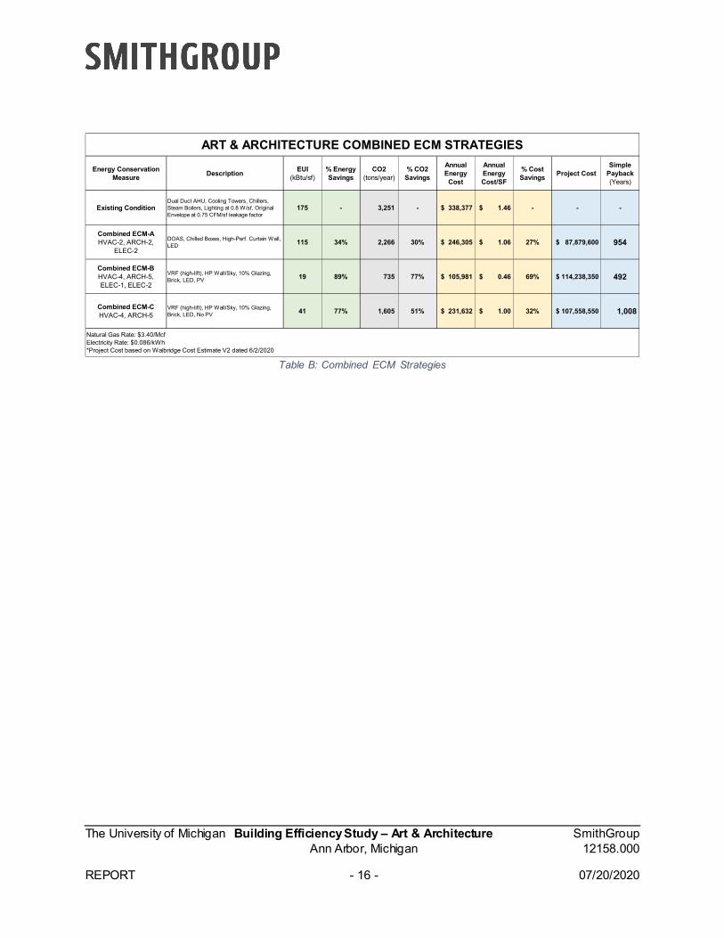
Table B: Combined ECM Strategies
Energy Conservation Measure Description EUI
(kBtu/sf)% Energy Savings
CO2 (tons/year)
% CO2 Savings
Annual Energy
Cost
Annual Energy Cost/SF
% Cost Savings Project Cost
Simple Payback (Years)
Existing ConditionDual Duct AHU, Cooling Towers, Chillers, Steam Boilers, Lighting at 0.8 W/sf, Original Envelope at 0.75 CFM/sf leakage factor
175 - 3,251 - $ 338,377 $ 1.46 - - -
Combined ECM-AHVAC-2, ARCH-2,
ELEC-2
DOAS, Chilled Boxes, High-Perf. Curtain Wall, LED 115 34% 2,266 30% $ 246,305 $ 1.06 27% $ 87,879,600 954
Combined ECM-BHVAC-4, ARCH-5,ELEC-1, ELEC-2
VRF (high-lift), HP Wall/Sky, 10% Glazing, Brick, LED, PV 19 89% 735 77% $ 105,981 $ 0.46 69% $ 114,238,350 492
Combined ECM-CHVAC-4, ARCH-5
VRF (high-lift), HP Wall/Sky, 10% Glazing, Brick, LED, No PV 41 77% 1,605 51% $ 231,632 $ 1.00 32% $ 107,558,550 1,008
ART & ARCHITECTURE COMBINED ECM STRATEGIES
Natural Gas Rate: $3.40/McfElectricity Rate: $0.086/kWh*Project Cost based on Walbridge Cost Estimate V2 dated 6/2/2020
The University of Michigan Building Efficiency Study – Art & Architecture SmithGroup Ann Arbor, Michigan 12158.000 REPORT - 17 - 07/20/2020
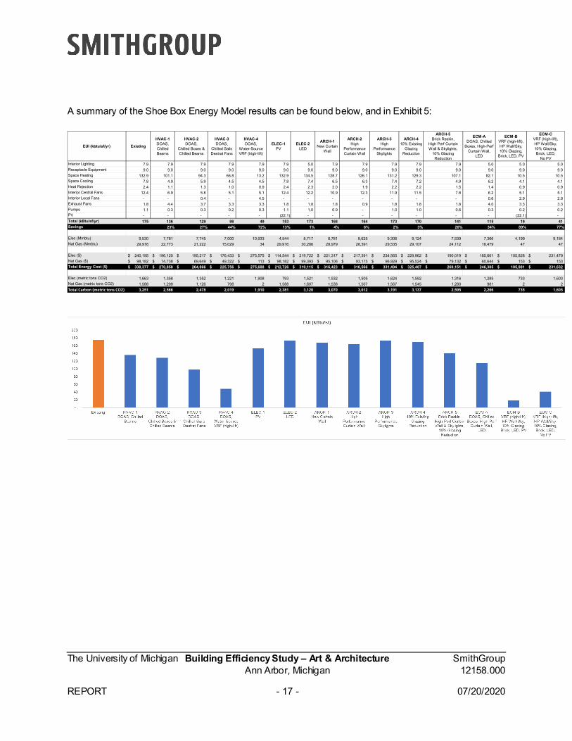
A summary of the Shoe Box Energy Model results can be found below, and in Exhibit 5:
EUI (kbtu/sf/yr) Existing
HVAC-1DOAS, Chilled Beams
HVAC-2DOAS,
Chilled Boxes &Chilled Beams
HVAC-3DOAS,
Chilled SailsDestrat Fans
HVAC-4DOAS,
Water-SourceVRF (high-lift)
ELEC-1PV
ELEC-2LED
ARCH-1 New Curtain
Wall
ARCH-2High
PerformanceCurtain Wall
ARCH-3High
PerformanceSkylights
ARCH-410% Existing
GlazingReduction
ARCH-5Brick Reskin,
High Perf CurtainWall & Skylights,
10% GlazingReduction
ECM-ADOAS, Chilled
Boxes, High-PerfCurtain Wall,
LED
ECM-BVRF (high-lift),HP Wall/Sky,10% Glazing,
Brick, LED, PV
ECM-CVRF (high-lift),HP Wall/Sky,10% Glazing,Brick, LED,
No PVInterior Lighting 7.9 7.9 7.9 7.9 7.9 7.9 5.0 7.9 7.9 7.9 7.9 7.9 5.0 5.0 5.0 Receptacle Equipment 9.0 9.0 9.0 9.0 9.0 9.0 9.0 9.0 9.0 9.0 9.0 9.0 9.0 9.0 9.0 Space Heating 132.9 101.1 94.3 66.8 13.2 132.9 134.5 128.7 126.1 131.2 129.3 107.1 82.1 10.5 10.5 Space Cooling 7.8 4.9 5.9 4.5 4.5 7.8 7.4 6.5 6.3 7.4 7.2 4.9 6.2 4.1 4.1 Heat Rejection 2.4 1.1 1.3 1.0 0.9 2.4 2.3 2.0 1.9 2.2 2.2 1.5 1.4 0.9 0.9 Interior Central Fans 12.4 6.9 5.8 5.1 5.1 12.4 12.2 10.9 12.3 11.9 11.5 7.8 6.2 5.1 5.1 Interior Local Fans - - 0.4 - 4.5 - - - - - - - 0.6 2.9 2.9 Exhaust Fans 1.8 4.4 3.7 3.3 3.3 1.8 1.8 1.8 0.9 1.8 1.8 1.8 4.0 3.3 3.3 Pumps 1.1 0.3 0.3 0.2 0.3 1.1 1.0 0.9 - 1.0 1.0 0.6 0.3 0.2 0.2 PV - - - - - (22.1) - - - - - - - (22.1) - Total (kBtu/sf/yr) 175 136 129 98 49 153 173 168 164 173 170 141 115 19 41 Savings 23% 27% 44% 72% 13% 1% 4% 6% 2% 3% 20% 34% 89% 77%
Elec (Mmbtu) 9,530 7,781 7,745 7,000 10,933 4,544 8,717 8,781 8,625 9,306 9,124 7,539 7,366 4,199 9,184 Nat Gas (Mmbtu) 29,916 22,773 21,222 15,029 34 29,916 30,286 28,979 28,391 29,535 29,107 24,112 18,479 47 47
Elec ($) 240,195$ 196,120$ 195,217$ 176,433$ 275,575$ 114,544$ 219,722$ 221,317$ 217,391$ 234,565$ 229,962$ 190,019$ 185,661$ 105,828$ 231,479$ Nat Gas ($) 98,182$ 74,738$ 69,649$ 49,322$ 113$ 98,182$ 99,393$ 95,106$ 93,175$ 96,929$ 95,524$ 79,132$ 60,644$ 153$ 153$ Total Energy Cost ($) 338,377$ 270,858$ 264,866$ 225,756$ 275,688$ 212,726$ 319,115$ 316,423$ 310,566$ 331,494$ 325,487$ 269,151$ 246,305$ 105,981$ 231,632$
Elec (metric tons CO2) 1,663 1,358 1,352 1,221 1,908 793 1,521 1,532 1,505 1,624 1,592 1,316 1,285 733 1,603 Nat Gas (metric tons CO2) 1,588 1,209 1,126 798 2 1,588 1,607 1,538 1,507 1,567 1,545 1,280 981 2 2 Total Carbon (metric tons CO2) 3,251 2,566 2,478 2,019 1,910 2,381 3,128 3,070 3,012 3,191 3,137 2,595 2,266 735 1,605
The University of Michigan Building Efficiency Study – Art & Architecture SmithGroup Ann Arbor, Michigan 12158.000 REPORT - 18 - 07/20/2020
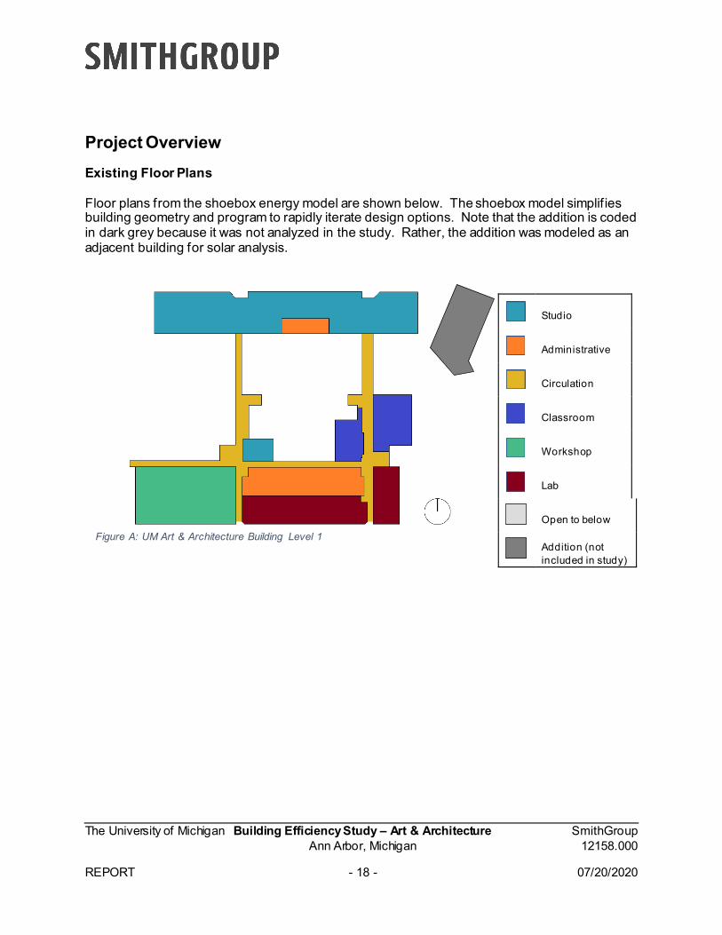
Project Overview Existing Floor Plans Floor plans from the shoebox energy model are shown below. The shoebox model simplif ies building geometry and program to rapidly iterate design options. Note that the addition is coded in dark grey because it was not analyzed in the study. Rather, the addition was modeled as an adjacent building for solar analysis.
Figure A: UM Art & Architecture Building Level 1
Studio
Administrative
Circulation
Classroom
Workshop
Lab
Open to below
Addition (not included in study)
The University of Michigan Building Efficiency Study – Art & Architecture SmithGroup Ann Arbor, Michigan 12158.000 REPORT - 19 - 07/20/2020
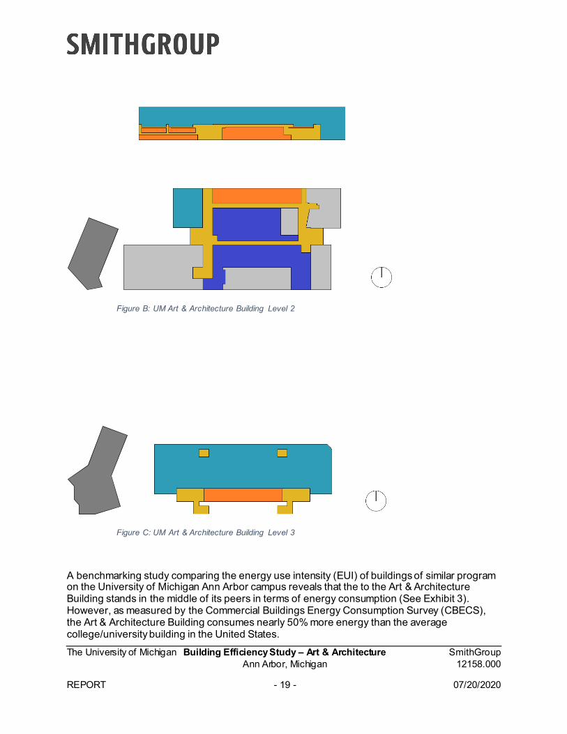
Figure B: UM Art & Architecture Building Level 2
Figure C: UM Art & Architecture Building Level 3
A benchmarking study comparing the energy use intensity (EUI) of buildings of similar program on the University of Michigan Ann Arbor campus reveals that the to the Art & Architecture Building stands in the middle of its peers in terms of energy consumption (See Exhibit 3). However, as measured by the Commercial Buildings Energy Consumption Survey (CBECS), the Art & Architecture Building consumes nearly 50% more energy than the average college/university building in the United States.
The University of Michigan Building Efficiency Study – Art & Architecture SmithGroup Ann Arbor, Michigan 12158.000 REPORT - 20 - 07/20/2020
Project Goals Goal 1: Provide high-level energy and carbon assessment for Art & Architecture Building Goal 2: Provide energy audit and ECM analysis for Art & Architecture Building, in line with UM Plant Blue sustainability goals of reducing greenhouse gas emissions by 25 percent.
University of Michigan – Ann Arbor Sustainability Goal Reporting Guidelines: Goal #1: Reduce Scope 1 & 2 Greenhouse Gas Emissions by 25%
“As an institution comprised of nearly 400 buildings covering over 37 million square feet, the University of Michigan (U-M) requires a significant amount of energy to meet the educational, research, and operational needs of the campus. An innovational leader, U-M strives to set the standards for sustainability, both in the classroom and through its physical operations. Announced in the fall of 2011, U-M aims to reduce its scope 1 and 2 greenhouse gas emissions from FY2006 levels by 25% by 2025. Achieving a goal such as this will require the development of new technology, improvement of existing technology, and behavioral changes within the University community.”
Goal 3: Create an assessment framework for other buildings/campus regions Data Collection and Benchmarking Historic Climate Analysis for Ann Arbor – See Exhibit 1.
Shoebox model outputs reflect historic climate data Future Climate Analysis for Ann Arbor – See Exhibit 2. Benchmarking – See Exhibit 3. UM Office of Campus Sustainability Energy Database Analysis – See Exhibit 4.
The University of Michigan Building Efficiency Study – Art & Architecture SmithGroup Ann Arbor, Michigan 12158.000 REPORT - 21 - 07/20/2020
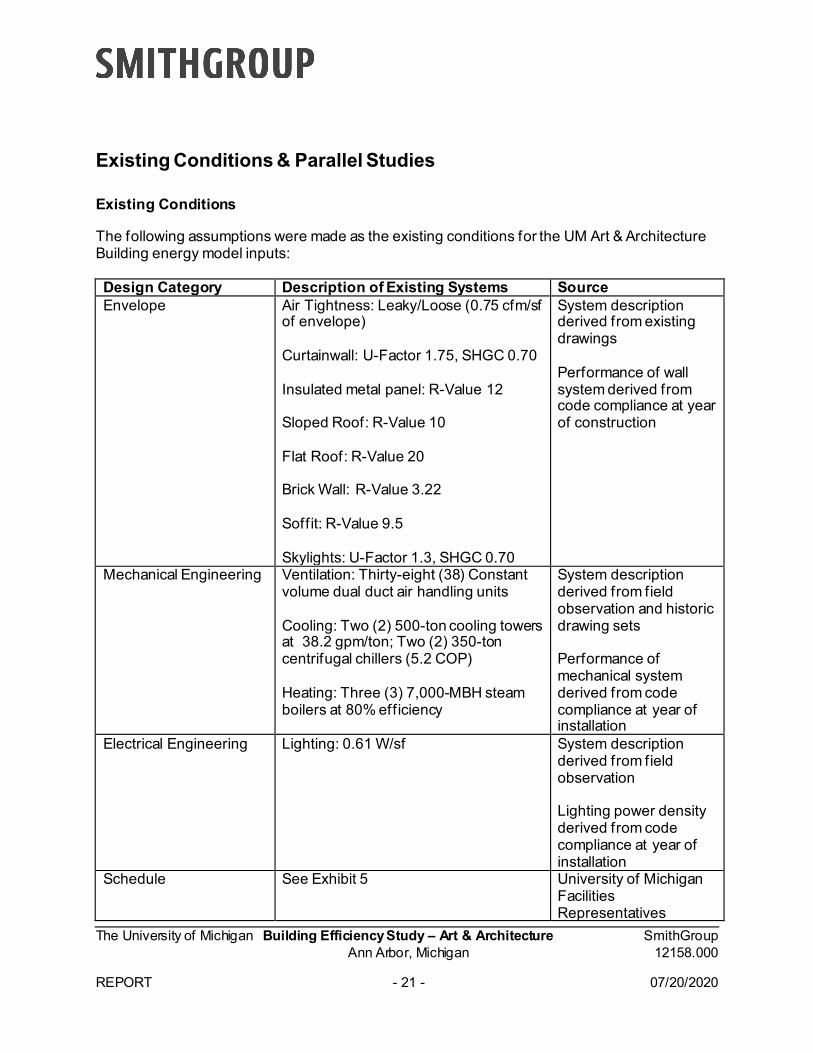
Existing Conditions & Parallel Studies Existing Conditions The following assumptions were made as the existing conditions for the UM Art & Architecture Building energy model inputs: Design Category Description of Existing Systems Source Envelope Air Tightness: Leaky/Loose (0.75 cfm/sf
of envelope) Curtainwall: U-Factor 1.75, SHGC 0.70 Insulated metal panel: R-Value 12 Sloped Roof: R-Value 10 Flat Roof: R-Value 20 Brick Wall: R-Value 3.22 Soffit: R-Value 9.5 Skylights: U-Factor 1.3, SHGC 0.70
System description derived from existing drawings Performance of wall system derived from code compliance at year of construction
Mechanical Engineering Ventilation: Thirty-eight (38) Constant volume dual duct air handling units Cooling: Two (2) 500-ton cooling towers at 38.2 gpm/ton; Two (2) 350-ton centrifugal chillers (5.2 COP) Heating: Three (3) 7,000-MBH steam boilers at 80% efficiency
System description derived from field observation and historic drawing sets Performance of mechanical system derived from code compliance at year of installation
Electrical Engineering Lighting: 0.61 W/sf System description derived from field observation Lighting power density derived from code compliance at year of installation
Schedule See Exhibit 5 University of Michigan Facilities Representatives
The University of Michigan Building Efficiency Study – Art & Architecture SmithGroup Ann Arbor, Michigan 12158.000 REPORT - 22 - 07/20/2020
Table: Existing Conditions District Improvements Integral Group is in the process of creating a district energy master plan, which to date includes: Geothermal heat exchange and the reuse of as much building energy as possible Low Temperature Hot Water (LTHW( at 120°F for Art & Architecture Building and as
many systems as possible (for cooling dominant campuses with ample availability of low-grade thermal energy sources/ sinks (i.e. geo-exchange) and the plant based on single stage lift heat recovery chillers)
Medium Temperature Hot Water (MTHW) at 145°F would likely be required for campuses with heating dominant demand and more constrained availability of low-grade thermal energy sources/ sinks requiring two-stage lift HRCHs
High Temperature Hot Water (HTHW) at 180°F would likely be required for the Central Campus where availability of low-grade thermal energy sources is limited. This will require combustion-based plant using biofuels.
The University of Michigan Building Efficiency Study – Art & Architecture SmithGroup Ann Arbor, Michigan 12158.000 REPORT - 23 - 07/20/2020
Analysis Included in Analysis The following were included in the building energy analysis: Basic building geometry and programming Mechanical systems per existing drawings and code compliance at year of installation1 Lighting systems per existing drawings and code compliance at year of installation Envelope per existing drawings and code compliance at year of installation Plug load, lighting, people, and mechanical equipment schedules per University of
Michigan input Excluded from Analysis The following were excluded from the building energy analysis: Load shedding: Energy benefit of load shedding is generally understood and is intended
to be part of the design process rather than analysis Change of occupancy and scheduling: Building upgrades preferred to have minimal
impact on curriculum Process loads: Process loads are not sub-metered; therefore, a realistic assumption
could not be provided. Additionally, it is assumed process load will not change with future building upgrades.
1 For example, actually efficiency of newly-replaced steam boilers unknown, but modeled at 80% per 2012 (year of installation) energy code
The University of Michigan Building Efficiency Study – Art & Architecture SmithGroup Ann Arbor, Michigan 12158.000 REPORT - 24 - 07/20/2020
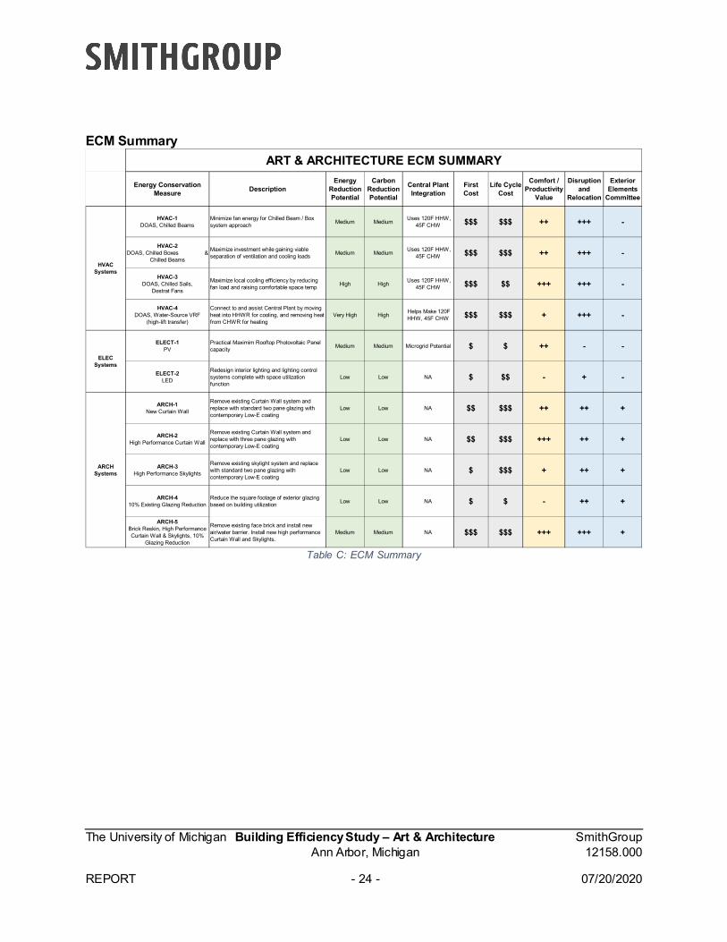
ECM Summary
Table C: ECM Summary
Energy Conservation Measure Description
Energy Reduction Potential
Carbon Reduction Potential
Central Plant Integration
First Cost
Life Cycle Cost
Comfort / Productivity
Value
Disruption and
Relocation
Exterior Elements
Committee
HVAC-1 DOAS, Chilled Beams
Minimize fan energy for Chilled Beam / Box system approach Medium Medium Uses 120F HHW,
45F CHW $$$ $$$ ++ +++ -
HVAC-2 DOAS, Chilled Boxes &
Chilled Beams
Maximize investment while gaining viable separation of ventilation and cooling loads Medium Medium Uses 120F HHW,
45F CHW $$$ $$$ ++ +++ -
HVAC-3 DOAS, Chilled Sails,
Destrat Fans
Maximize local cooling efficiency by reducing fan load and raising comfortable space temp High High Uses 120F HHW,
45F CHW $$$ $$ +++ +++ -
HVAC-4 DOAS, Water-Source VRF
(high-lift transfer)
Connect to and assist Central Plant by moving heat into HHWR for cooling, and removing heat from CHWR for heating
Very High High Helps Make 120F HHW, 45F CHW $$$ $$$ + +++ -
ELECT-1 PV
Practical Maximim Rooftop Photovoltaic Panel capacity Medium Medium Microgrid Potential $ $ ++ - -
ELECT-2 LED
Redesign interior lighting and lighting control systems complete with space utilization function
Low Low NA $ $$ - + -
ARCH-1New Curtain Wall
Remove existing Curtain Wall system and replace with standard two pane glazing with contemporary Low-E coating
Low Low NA $$ $$$ ++ ++ +
ARCH-2High Performance Curtain Wall
Remove existing Curtain Wall system and replace with three pane glazing with contemporary Low-E coating
Low Low NA $$ $$$ +++ ++ +
ARCH-3High Performance Skylights
Remove existing skylight system and replace with standard two pane glazing with contemporary Low-E coating
Low Low NA $ $$$ + ++ +
ARCH-410% Existing Glazing Reduction
Reduce the square footage of exterior glazing based on building utilization Low Low NA $ $ - ++ +
ARCH-5Brick Reskin, High Performance Curtain Wall & Skylights, 10%
Glazing Reduction
Remove existing face brick and install new air/water barrier. Install new high performance Curtain Wall and Skylights.
Medium Medium NA $$$ $$$ +++ +++ +
ART & ARCHITECTURE ECM SUMMARY
HVAC Systems
ELEC Systems
ARCH Systems
The University of Michigan Building Efficiency Study – Art & Architecture SmithGroup Ann Arbor, Michigan 12158.000 REPORT - 25 - 07/20/2020
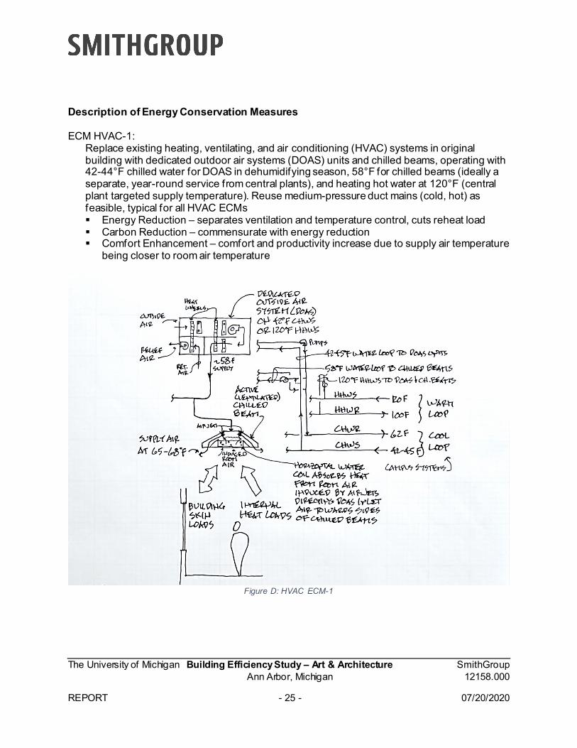
Description of Energy Conservation Measures ECM HVAC-1:
Replace existing heating, ventilating, and air conditioning (HVAC) systems in original building with dedicated outdoor air systems (DOAS) units and chilled beams, operating with 42-44°F chilled water for DOAS in dehumidifying season, 58°F for chilled beams (ideally a separate, year-round service from central plants), and heating hot water at 120°F (central plant targeted supply temperature). Reuse medium-pressure duct mains (cold, hot) as feasible, typical for all HVAC ECMs Energy Reduction – separates ventilation and temperature control, cuts reheat load Carbon Reduction – commensurate with energy reduction Comfort Enhancement – comfort and productivity increase due to supply air temperature
being closer to room air temperature
Figure D: HVAC ECM-1
The University of Michigan Building Efficiency Study – Art & Architecture SmithGroup Ann Arbor, Michigan 12158.000 REPORT - 26 - 07/20/2020
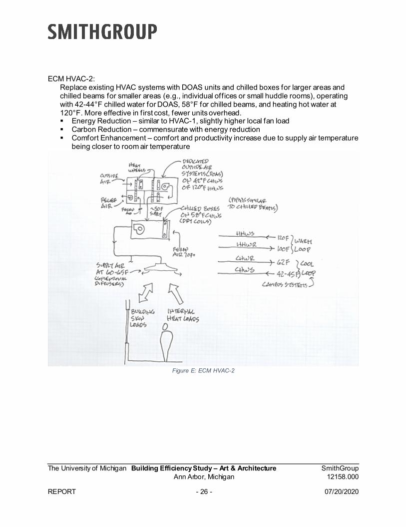
ECM HVAC-2: Replace existing HVAC systems with DOAS units and chilled boxes for larger areas and chilled beams for smaller areas (e.g., individual offices or small huddle rooms), operating with 42-44°F chilled water for DOAS, 58°F for chilled beams, and heating hot water at 120°F. More effective in first cost, fewer units overhead. Energy Reduction – similar to HVAC-1, slightly higher local fan load Carbon Reduction – commensurate with energy reduction Comfort Enhancement – comfort and productivity increase due to supply air temperature
being closer to room air temperature
Figure E: ECM HVAC-2
The University of Michigan Building Efficiency Study – Art & Architecture SmithGroup Ann Arbor, Michigan 12158.000 REPORT - 27 - 07/20/2020
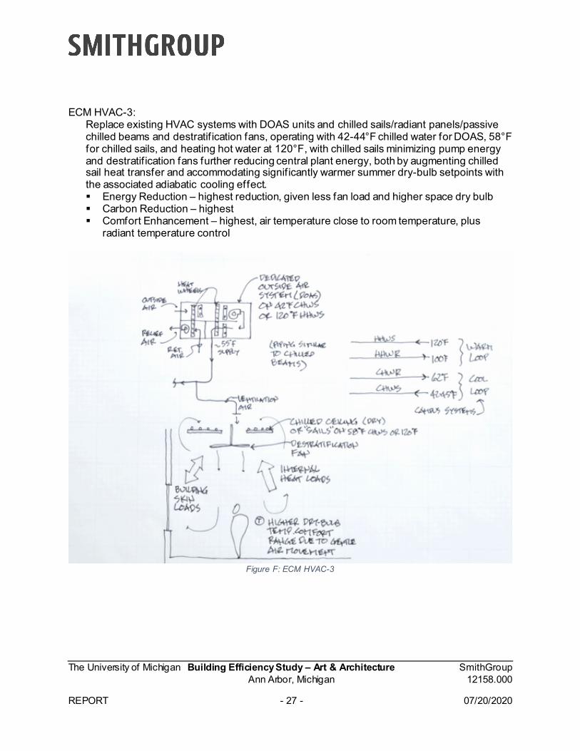
ECM HVAC-3: Replace existing HVAC systems with DOAS units and chilled sails/radiant panels/passive chilled beams and destratif ication fans, operating with 42-44°F chilled water for DOAS, 58°F for chilled sails, and heating hot water at 120°F, with chilled sails minimizing pump energy and destratif ication fans further reducing central plant energy, both by augmenting chilled sail heat transfer and accommodating significantly warmer summer dry-bulb setpoints with the associated adiabatic cooling effect. Energy Reduction – highest reduction, given less fan load and higher space dry bulb Carbon Reduction – highest Comfort Enhancement – highest, air temperature close to room temperature, plus
radiant temperature control
Figure F: ECM HVAC-3
The University of Michigan Building Efficiency Study – Art & Architecture SmithGroup Ann Arbor, Michigan 12158.000 REPORT - 28 - 07/20/2020
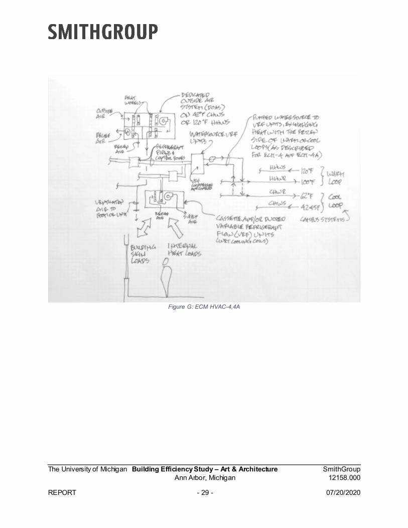
ECM HVAC-4: Replace existing HVAC systems with DOAS and water-source variable refrigerant flow (VRF) systems, with a net-energy building water loop that recirculates heat within the building, then rejects excess heat in summer to the return side of the heating hot water site system (with that system possibly operating at lower temperatures in summer at 90°F heating hot water return), and takes heat in winter from the return side of the chilled water site system at 58°F. This presents the central plant with a negative load in both seasons, while avoiding dual-compression effects between buildings and plants. Domestic hot water heating is accomplished with a conventional or trans-critical CO2 heat pump, also working off of the chilled water return. It also increases building resiliency, in that it can operate off of either warm or cool loop from the central plant if one is built before the other, or one goes down. Energy Reduction – with the stated goal being to “see how far building loads can be
reduced,” this approach drops them to below zero (i.e., actually helping the central plant, as seen from the central plant warm loop and cool loop).
Carbon Reduction – commensurate with energy reduction Comfort Enhancement – comparable to variable air volume (VAV) system
ECM HVAC-4A (low-lift heat rejection to the “easy” campus loop was considered only to understand the EUI delta compared to the high-lift approach of HVAC-4)2:
Replace existing HVAC systems with DOAS and water-source VRF systems, with a net-energy building water loop that recirculates heat within the building, then rejects excess heat in summer to the return side of the chilled water site system at 58°F, and taking heat from the heating hot water return system at 100°F, presenting the central plant with the next best thing to negative loads, that being not using any supply water capacity for either system, only return water, which increases Central Plant Coefficients of Performance. Domestic Hot Water is heated with a trans-critical CO2 heat pump, working off of the chilled water return. Offers the same phasing- and redundancy-based resiliency as ECM HVAC-4. Energy Reduction – strong at building level and at central plant level Carbon Reduction – commensurate with energy reduction Comfort Enhancement – comparable to VAV system
2 Energy and costing analysis for HVAC-4A not included in study due to large deficit in energy savings compared to HVAC-4
The University of Michigan Building Efficiency Study – Art & Architecture SmithGroup Ann Arbor, Michigan 12158.000 REPORT - 29 - 07/20/2020
Figure G: ECM HVAC-4,4A
The University of Michigan Building Efficiency Study – Art & Architecture SmithGroup Ann Arbor, Michigan 12158.000 REPORT - 30 - 07/20/2020
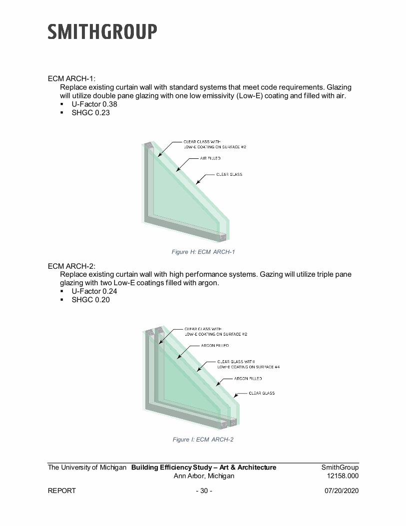
ECM ARCH-1: Replace existing curtain wall with standard systems that meet code requirements. Glazing will utilize double pane glazing with one low emissivity (Low-E) coating and filled with air. U-Factor 0.38 SHGC 0.23
Figure H: ECM ARCH-1
ECM ARCH-2: Replace existing curtain wall with high performance systems. Gazing will utilize triple pane glazing with two Low-E coatings filled with argon. U-Factor 0.24 SHGC 0.20
Figure I: ECM ARCH-2
The University of Michigan Building Efficiency Study – Art & Architecture SmithGroup Ann Arbor, Michigan 12158.000 REPORT - 31 - 07/20/2020
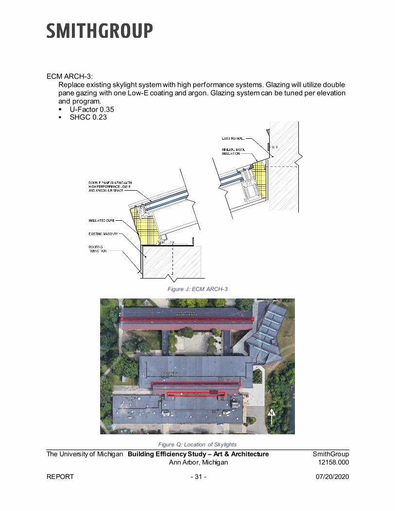
ECM ARCH-3: Replace existing skylight system with high performance systems. Glazing will utilize double pane gazing with one Low-E coating and argon. Glazing system can be tuned per elevation and program. U-Factor 0.35 SHGC 0.23
Figure J: ECM ARCH-3
Figure Q: Location of Skylights
The University of Michigan Building Efficiency Study – Art & Architecture SmithGroup Ann Arbor, Michigan 12158.000 REPORT - 32 - 07/20/2020
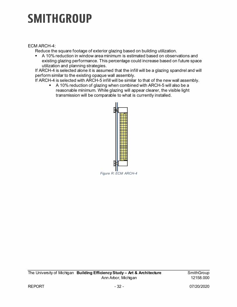
ECM ARCH-4: Reduce the square footage of exterior glazing based on building utilization. A 10% reduction in window area minimum is estimated based on observations and
existing glazing performance. This percentage could increase based on future space utilization and planning strategies.
If ARCH-4 is selected alone it is assumed that the infill will be a glazing spandrel and will perform similar to the existing opaque wall assembly. If ARCH-4 is selected with ARCH-5 infill will be similar to that of the new wall assembly.
A 10% reduction of glazing when combined with ARCH-5 will also be a reasonable minimum. While glazing will appear clearer, the visible light transmission will be comparable to what is currently installed.
Figure R: ECM ARCH-4
The University of Michigan Building Efficiency Study – Art & Architecture SmithGroup Ann Arbor, Michigan 12158.000 REPORT - 33 - 07/20/2020
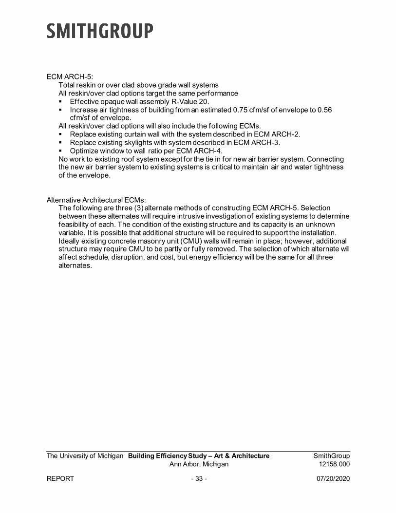
ECM ARCH-5: Total reskin or over clad above grade wall systems All reskin/over clad options target the same performance Effective opaque wall assembly R-Value 20. Increase air tightness of building from an estimated 0.75 cfm/sf of envelope to 0.56
cfm/sf of envelope. All reskin/over clad options will also include the following ECMs. Replace existing curtain wall with the system described in ECM ARCH-2. Replace existing skylights with system described in ECM ARCH-3. Optimize window to wall ratio per ECM ARCH-4. No work to existing roof system except for the tie in for new air barrier system. Connecting the new air barrier system to existing systems is critical to maintain air and water tightness of the envelope.
Alternative Architectural ECMs:
The following are three (3) alternate methods of constructing ECM ARCH-5. Selection between these alternates will require intrusive investigation of existing systems to determine feasibility of each. The condition of the existing structure and its capacity is an unknown variable. It is possible that additional structure will be required to support the installation. Ideally existing concrete masonry unit (CMU) walls will remain in place; however, additional structure may require CMU to be partly or fully removed. The selection of which alternate will affect schedule, disruption, and cost, but energy efficiency will be the same for all three alternates.
The University of Michigan Building Efficiency Study – Art & Architecture SmithGroup Ann Arbor, Michigan 12158.000 REPORT - 34 - 07/20/2020
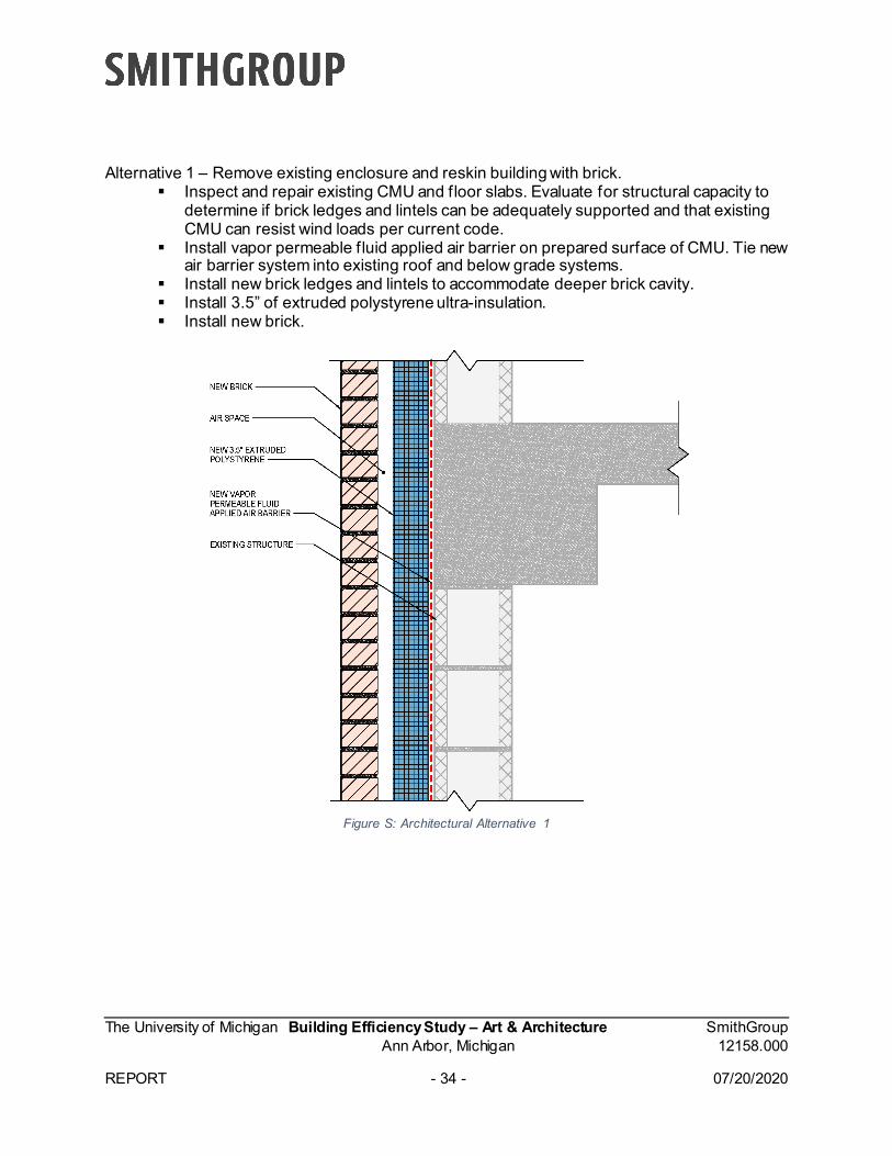
Alternative 1 – Remove existing enclosure and reskin building with brick. Inspect and repair existing CMU and floor slabs. Evaluate for structural capacity to
determine if brick ledges and lintels can be adequately supported and that existing CMU can resist wind loads per current code.
Install vapor permeable fluid applied air barrier on prepared surface of CMU. Tie new air barrier system into existing roof and below grade systems.
Install new brick ledges and lintels to accommodate deeper brick cavity. Install 3.5” of extruded polystyrene ultra-insulation. Install new brick.
Figure S: Architectural Alternative 1
The University of Michigan Building Efficiency Study – Art & Architecture SmithGroup Ann Arbor, Michigan 12158.000 REPORT - 35 - 07/20/2020
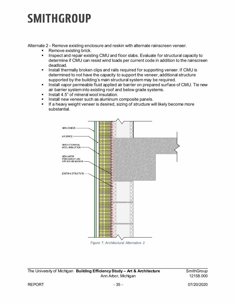
Alternate 2 - Remove existing enclosure and reskin with alternate rainscreen veneer. Remove existing brick. Inspect and repair existing CMU and floor slabs. Evaluate for structural capacity to
determine if CMU can resist wind loads per current code in addition to the rainscreen deadload.
Install thermally broken clips and rails required for supporting veneer. If CMU is determined to not have the capacity to support the veneer, additional structure supported by the building’s main structural system may be required.
Install vapor permeable fluid applied air barrier on prepared surface of CMU. Tie new air barrier system into existing roof and below grade systems.
Install 4.5” of mineral wool insulation. Install new veneer such as aluminum composite panels. If a heavy weight veneer is desired, sizing of structure will likely become more
substantial.
Figure T: Architectural Alternative 2
The University of Michigan Building Efficiency Study – Art & Architecture SmithGroup Ann Arbor, Michigan 12158.000 REPORT - 36 - 07/20/2020
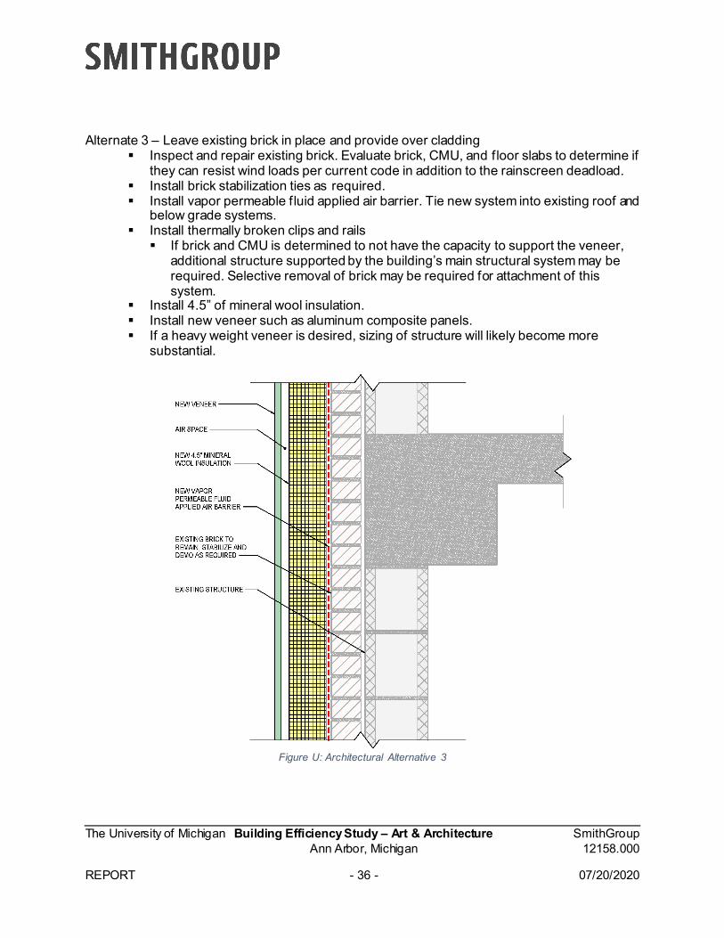
Alternate 3 – Leave existing brick in place and provide over cladding Inspect and repair existing brick. Evaluate brick, CMU, and floor slabs to determine if
they can resist wind loads per current code in addition to the rainscreen deadload. Install brick stabilization ties as required. Install vapor permeable fluid applied air barrier. Tie new system into existing roof and
below grade systems. Install thermally broken clips and rails If brick and CMU is determined to not have the capacity to support the veneer,
additional structure supported by the building’s main structural system may be required. Selective removal of brick may be required for attachment of this system.
Install 4.5” of mineral wool insulation. Install new veneer such as aluminum composite panels. If a heavy weight veneer is desired, sizing of structure will likely become more
substantial.
Figure U: Architectural Alternative 3
The University of Michigan Building Efficiency Study – Art & Architecture SmithGroup Ann Arbor, Michigan 12158.000 REPORT - 37 - 07/20/2020
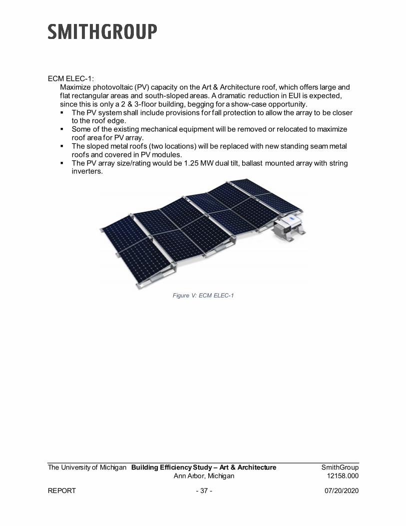
ECM ELEC-1: Maximize photovoltaic (PV) capacity on the Art & Architecture roof, which offers large and flat rectangular areas and south-sloped areas. A dramatic reduction in EUI is expected, since this is only a 2 & 3-floor building, begging for a show-case opportunity. The PV system shall include provisions for fall protection to allow the array to be closer
to the roof edge. Some of the existing mechanical equipment will be removed or relocated to maximize
roof area for PV array. The sloped metal roofs (two locations) will be replaced with new standing seam metal
roofs and covered in PV modules. The PV array size/rating would be 1.25 MW dual tilt, ballast mounted array with string
inverters.
Figure V: ECM ELEC-1
The University of Michigan Building Efficiency Study – Art & Architecture SmithGroup Ann Arbor, Michigan 12158.000 REPORT - 38 - 07/20/2020
ECM ELEC-2: Remove all existing lighting fixtures and replace with new high-efficacy light-emitting diode (LED) lighting fixtures and controls. We envision a comprehensive review of both quality and quantity of f ixtures paired with network lighting controls, vacancy sensors and daylight harvesting sensors. Therefore, this is not just a one-for-one fixture replacement. ASHRAE Standard 90.1-2013 (Energy Standard for Buildings Except Low-Rise
Residential Buildings) allowance for a school/university building is 0.87 W/SF. Target lighting power density (LPD) for the renovated building would be 30% below the
ASHRAE 90.1 allowance or 0.61 W/SF. Energy Reduction – Slight improvement over existing LEDs Carbon Reduction – Slight improvement over existing Comfort Enhancement – Opportunity for further enhancement and performance
The University of Michigan Building Efficiency Study – Art & Architecture SmithGroup Ann Arbor, Michigan 12158.000 REPORT - 39 - 07/20/2020
Combined ECMs The following is a combination of aforementioned ECMs that were modeled for energy and cost analysis: Combined ECM-A ECM HVAC-2: DOAS, Chilled Boxes ECM ARCH-2: High-Perf. Curtain Wall ECM ELEC-2: LED Advantages/Disadvantages:
The chilled box system has the advantages of hydronic piping and fan terminals with dry coils, which require only conventional maintenance. It relies primarily on large equipment in central plants and significant pumping between building and plant, which concentrates equipment replacement to fewer locations, but requires significant pumping between the plant and building to do so. (The DOAS aspect is similar for each of the combined ECMs.) New lighting fixtures and controls improve not only energy performance, but also functional light levels throughout the facility for improved occupant comfort. Daylight harvesting controls will dim and/or turn lighting off when sufficient daylight is present. Replacing the curtain wall is less invasive than other architectural ECMs. It will provide a higher level of human comfort near vertical glazing systems along with the energy benefits, but increased performance will affect a smaller percentage of the exterior envelope when compared to ECM ARCH-5.
Combined ECM-B ECM HVAC-4: VRF (high-lift) ECM ARCH-5 (note this includes window [ECM ARCH-2] and skylight [ECM ARCH-3]
replacement): High Performance (HP) Wall/Sky, 10% Glazing, Brick ECM ELEC-2: LED ECM ELEC-1: PV Advantages/Disadvantages:
Generally, a VRF system requires skilled maintenance and may warrant costly system updates at times of building renovations. This VRF system performs more refrigeration locally, which has the advantage of more granular management/synergy in heat transfer, less pumping between building and central plant, relying on the central plant only for net energy transfer, in a unique way that the plant sees as reducing its load rather than increasing it. However, VRF suppliers include some proprietary differences, they require extensive local refrigeration piping, more locations to address in an end-of-life condition, and the potential for more regulation of refrigerant. A photovoltaic (PV) system provides an on-site renewable source of energy with a large reduction in EUI. The proposed racking would be a ballast system to avoid roof penetrations. The PV would require little annual maintenance. The downside of PV is the high initial cost. Replacing the entire building skin is highly invasive, and there are many unknowns related to the condition of the existing structure, but replacing the skin will provide a building that has a higher resistance to air and water infiltration with very strong energy benefits.
The University of Michigan Building Efficiency Study – Art & Architecture SmithGroup Ann Arbor, Michigan 12158.000 REPORT - 40 - 07/20/2020
Combined ECM-C: ECM HVAC-4: VRF (high-lift) ECM ARCH-5 (note this includes window [ECM ARCH-2] and skylight [ECM ARCH-3]
replacement): HP Wall/Sky, 10% Glazing, Brick No PV Advantages/Disadvantages:
Generally, a VRF system requires skilled maintenance and may warrant costly system updates at times of building renovations. This VRF system performs more refrigeration locally, which has the advantage of more granular management/synergy in heat transfer, less pumping between building and central plant, relying on the central plant only for net energy transfer, in a unique way that the plant sees as reducing its load rather than increasing it. However, VRF suppliers include some proprietary differences, they require extensive local refrigeration piping, more locations to address in an end-of-life condition, and the potential for more regulation of refrigerant. Replacing the entire building skin is highly invasive, and there are many unknowns related to the condition of the existing structure, but replacing the skin will provide a building that has a higher resistance to air and water infiltration with very strong energy benefits.
The University of Michigan Building Efficiency Study – Art & Architecture SmithGroup Ann Arbor, Michigan 12158.000
REPORT - 41 - 07/20/2020
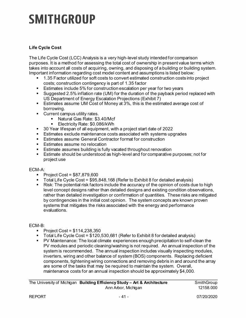
Life Cycle Cost
The Life Cycle Cost (LCC) Analysis is a very high-level study intended for comparison purposes. It is a method for assessing the total cost of ownership in present value terms which takes into account all costs of acquiring, owning, and disposing of a building or building system. Important information regarding cost model content and assumptions is listed below: 1.35 Factor utilized for soft costs to convert estimated construction costs into project
costs; construction contingency is part of 1.35 factor Estimates include 5% for construction escalation per year for two years Suggested 2.5% inflation rate (UM) for the duration of the payback period replaced with
US Department of Energy Escalation Projections (Exhibit 7) Estimates assume UM Cost of Money at 3%, this is the estimated average cost of
borrowing. Current campus utility rates.
Natural Gas Rate: $3.40/Mcf Electricity Rate: $0.086/kWh
30 Year lifespan of all equipment, with a project start date of 2022 Estimates exclude maintenance costs associated with systems upgrades Estimates assume General Contractor format for construction Estimates assume no relocation Estimate assumes building is fully vacated throughout renovation Estimate should be understood as high-level and for comparative purposes; not for
project use
ECM-A: Project Cost = $87,879,600 Total Life Cycle Cost = $95,848,168 (Refer to Exhibit 8 for detailed analysis) Risk: The potential risk factors include the accuracy of the opinion of costs due to high
level concept designs rather than detailed designs and existing condition observations,rather than detailed investigation or confirmation of quantities. These risks are mitigatedby contingencies in the initial cost opinion. The system concepts are known provensystems that mitigates the risks associated with the energy and performanceevaluations.
ECM-B: Project Cost = $114,238,350 Total Life Cycle Cost = $120,530,681 (Refer to Exhibit 8 for detailed analysis) PV Maintenance: The local climate experiences enough precipitation to self-clean the
PV modules and periodic cleaning/washing is not required. An annual inspection of the system is recommended. The annual inspection includes visually inspecting modules,inverters, wiring and other balance of system (BOS) components. Replacing deficientcomponents, tightening wiring connections and removing debris in and around the arrayare some of the tasks that may be required to maintain the system. Overall,maintenance costs for an annual inspection should be approximately $4,000.
The University of Michigan Building Efficiency Study – Art & Architecture SmithGroup Ann Arbor, Michigan 12158.000
REPORT - 42 - 07/20/2020
Risk: The potential risk factors include the accuracy of the opinion of costs due to highlevel concept designs rather than detailed designs and existing condition observations,rather than detailed investigation or confirmation of quantities. These risks are mitigatedby contingencies in the initial cost opinion. The new enclosure system with this optionincludes more risk associated with unforeseen existing conditions regarding the integrityof the existing structural system that could support the new enclosure.
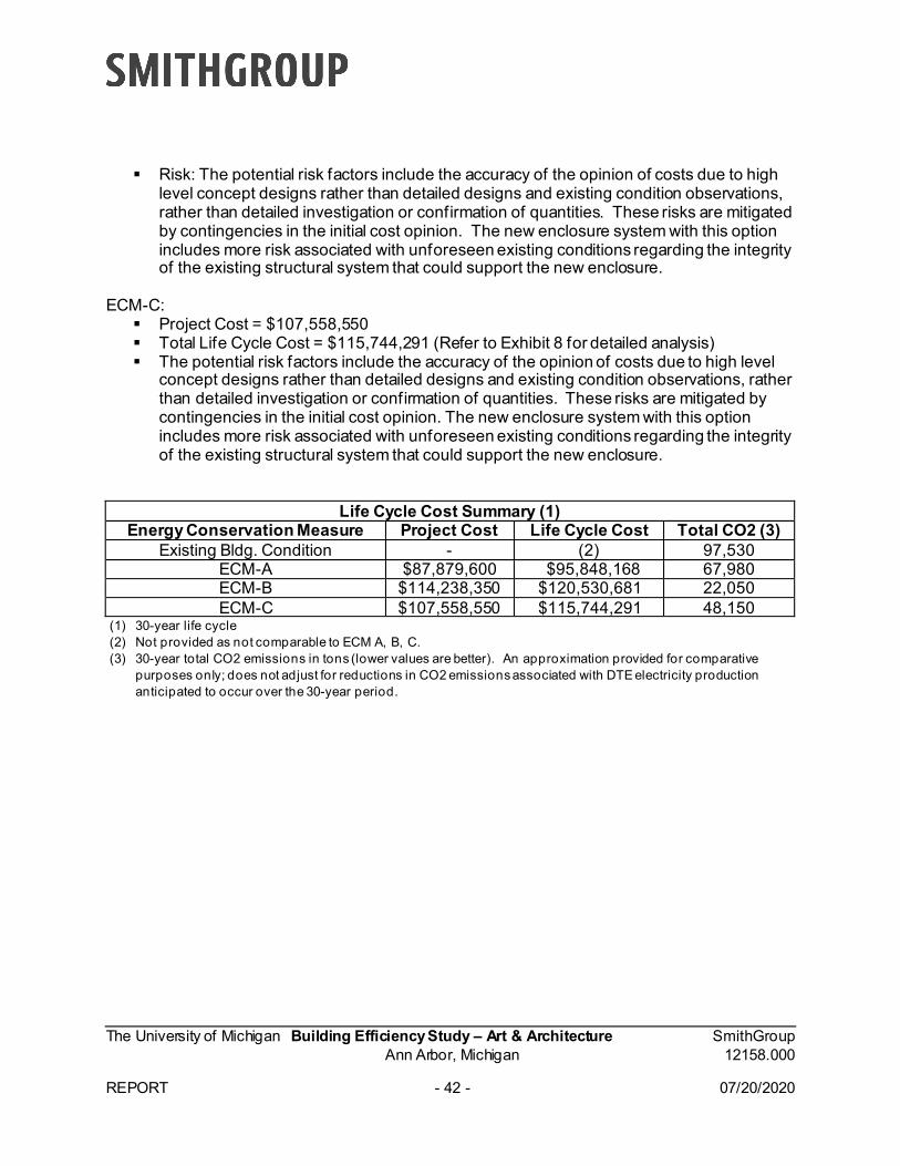
ECM-C: Project Cost = $107,558,550 Total Life Cycle Cost = $115,744,291 (Refer to Exhibit 8 for detailed analysis) The potential risk factors include the accuracy of the opinion of costs due to high level
concept designs rather than detailed designs and existing condition observations, rather than detailed investigation or confirmation of quantities. These risks are mitigated bycontingencies in the initial cost opinion. The new enclosure system with this optionincludes more risk associated with unforeseen existing conditions regarding the integrityof the existing structural system that could support the new enclosure.
Life Cycle Cost Summary (1) Energy Conservation Measure Project Cost Life Cycle Cost Total CO2 (3)
Existing Bldg. Condition - (2) 97,530 ECM-A $87,879,600 $95,848,168 67,980 ECM-B $114,238,350 $120,530,681 22,050 ECM-C $107,558,550 $115,744,291 48,150
(1) 30-year life cycle(2) Not provided as not comparable to ECM A, B, C.(3) 30-year total CO2 emissions in tons (lower values are better). An approximation provided for comparative
purposes only; does not adjust for reductions in CO2 emissions associated with DTE electricity productionanticipated to occur over the 30-year period.
The University of Michigan Building Efficiency Study – Couzens Residential Hall SmithGroup Ann Arbor, Michigan 12158.000
REPORT - 43 - 02/19/2021
Executive Summary
Introduction This study was commissioned by the President’s Commission on Carbon Neutrality (PCCN) to evaluate the existing Couzens Residential Hall (Couzens), circa 1926 with a major renovation in 2011, and identify Energy Conservation Measure (ECM) strategies to reduce energy demand and associated carbon emissions as low as possible. The design team started by visiting the building, collecting existing utility data, and reviewing the existing drawings. Their initial task was to determine how the current building was performing, to set a benchmark for comparison. Due to the major renovation in 2011 and potential future renovations to the site utilities, the team analyzed several approaches for Couzens that could be applied to similar building types that may not have had a recent renovation.
Then the team developed nineteen (19) individual ECMs, and six (6) combined ECMs that were evaluated, and cost estimated. The ECM strategies included mechanical and electrical building systems, the building enclosure itself, as well as various combinations of the individual ECMs. All ECM’s are within the Couzens building and not adjacent sites or buildings. A summary of the ECMs is contained in Table A (individual) and Table B (combined) on pages 6 & 7 of the report. More in-depth descriptions of each of the ECMs can be found on pages 9-29, including explanatory graphics. The combined ECMs were as follows:
● ECM Scenario A: This ECM reflects a combination of ECMs that the team estimatedwould typically be done under current UM Design Guidelines during a buildingrenovation.
● ECM Scenario B: This ECM reflects a combination of ECMs selected to produce themaximum reduction in carbon.
● ECM Scenario C: This ECM combination is the same as ECM B but with no renewableenergy, photovoltaics (PV).
● ECM Scenario D: This ECM combination aims to reduce project costs and still achieve ahealthy carbon reduction result. This combination includes the same HVAC ECM’s as B& C but only PV for electrical and solar shading for architectural.
● ECM Scenario E: This ECM combination aims to reduce project costs and still achieve ahealthy carbon reduction result without PV or solar shading.
● ECM Scenario F: This ECM combination aims to produce the maximum reduction incarbon utilizing the existing campus infrastructure without any renewable energy (PV).
To be judicious with the budget and schedule allocated for the study, shoebox (simplified) energy modeling was employed to compare the original building energy performance with the proposed ECM energy performance.
Couzens Residence Hall Building Energy Efficiency Study

The University of Michigan Building Efficiency Study – Couzens Residential Hall SmithGroup Ann Arbor, Michigan 12158.000
REPORT - 44- 02/19/2021
Project Costs To determine the estimated Project Costs of the various scenarios, the team worked with a Construction Manager to develop high-level construction cost estimates (see Exhibit 6 – Costs Analysis, the Opinion of Probable Cost (OPC). Although the OPCs could be perceived as high when comparing specific ECMs to various benchmarks, it is important to consider that these estimates consider the specific existing conditions at Couzens and include the full scope of associated work in Couzens to implement the ECMs. The full scope of this associated work is detailed in the Report and Appendix and provides a comprehensive understanding of the full scope of associated construction work that is required to implement each ECM. The total estimated Project Costs for the scenarios include the estimated construction costs, related construction costs (such as hazardous materials abatement and City utilities costs), contingencies, and professional fees and therefore represents the total costs anticipated to implement the various ECMs and bundled ECM scenarios.
Analysis of the ECMs As noted, the study looked at the simple payback for each of the ECMs. The study calculated simple payback in years as the difference between the Project Cost divided by the Annual Energy Cost savings. The simple paybacks assumed the existing system(s) did not need to be replaced, which is reasonable given that the building recently underwent a major renovation. This assumption produces long simple paybacks. A comparative example would be replacing your home's windows solely for the purpose of gaining the benefit of improved energy efficiency. The EUI (energy use per square foot per year) was calculated for each of the ECMs. The most promising and compatible discipline ECMs were combined and then analyzed via a very high-level Life Cycle Cost (LCC) analysis for comparative purposes, see pages 43-45 of the report. LCC is a method for assessing the total cost of ownership in present value terms, which considers all costs of acquiring, owning, and disposing of a building or building system. The tables below summarize the results of the Simple Payback and Life Cycle Costs analysis for each of the ECM scenarios.
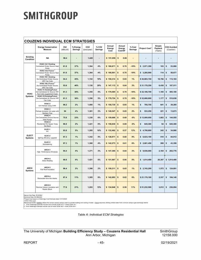
The University of Michigan Building Efficiency Study – Couzens Residential Hall SmithGroup Ann Arbor, Michigan 12158.000
REPORT - 45- 02/19/2021
Table A: Individual ECM Strategies
Energy Conservation Measure
EUI (kBtu/sf)
% Energy Savings
CO2 (tons/year)
% CO2 Savings
Annual Energy
Cost
Annual Energy Cost/SF
% Cost Savings
Project Cost* Simple
Payback (Years)
CO2 Avoided (Cost/ton)
Existing Condition
NA 98.4 - 1,420 - $ 151,956 $ 0.66 - - - -
HVAC-1A-1 ExistingCentralized Water Source Heat
Pump 61.8 37% 1,364 4% $ 180,671 $ 0.78 -19% $ 2,971,350 103 $ 53,060
HVAC-1A-2 Future 1
Centralized Water Source Heat Pump
61.6 37% 1,364 4% $ 180,901 $ 0.78 -19% $ 3,285,900 114 $ 58,677
HVAC-1B-1 ExistingDe-Centralized Water Source
VRF Fan Coils54.4 45% 1,152 19% $ 150,314 $ 0.65 1% $ 30,863,700 18,796 $ 115,163
HVAC-1B-2 Future 2
De-Centralized Water Source VRF Fan Coils
53.6 46% 1,130 20% $ 147,113 $ 0.64 3% $ 31,178,250 6,438 $ 107,511
HVAC-1C Existing/FutureDe-Centralized Air Source VRF
Fan Coils (supplement heat)61.3 38% 1,355 5% $ 179,585 $ 0.78 -18% $ 32,186,700 1,165 $ 495,180
HVAC-1D Existing/Future De-Centralized Air Source VRF
Fan Coils61.3 38% 1,356 5% $ 179,724 $ 0.78 -18% $ 32,680,800 1,177 $ 510,638
HVAC-2OA Preheat Using CHW
96.2 2% 1,400 1% $ 150,730 $ 0.65 1% $ 785,700 641 $ 39,285
HVAC-3Preheat domestic hot water with
Sanitary Flow94 4% 1,381 3% $ 149,547 $ 0.65 2% $ 533,250 221 $ 13,673
HVAC-4De-Centralized Ground Source
Heat Pumps75.8 23% 1,330 6% $ 159,686 $ 0.69 -5% $ 13,009,950 1,683 $ 144,555
HVAC-6Residential Rm Space Temp
Set-Back 96.8 2% 1,421 0% $ 158,830 $ 0.69 -5% $ 645,300 94 $ 645,300
ELEC-1PV
93.8 5% 1,285 10% $ 132,462 $ 0.57 13% $ 4,708,800 242 $ 34,880
ELEC-2lighting efficiency upgrade
97.3 1% 1,342 5% $ 138,971 $ 0.60 9% $ 6,623,100 510 $ 84,912
ELEC-3Submetering
97.3 1% 1,360 4% $ 142,273 $ 0.61 6% $ 2,601,450 269 $ 43,358
ARCH-1High Performance Windows
94.4 4% 1,371 3% $ 147,365 $ 0.64 3% $ 9,936,000 2,164 $ 202,776
ARCH-2Solar Shading
98.6 0% 1,421 0% $ 151,867 $ 0.66 0% $ 1,814,400 20,387 $ 1,814,400
ARCH-3Flat Roof Insulation
96.4 2% 1,398 2% $ 150,211 $ 0.65 1% $ 2,743,200 1,572 $ 124,691
ARCH-4Reinsulate from the interior
87.4 11% 1,305 8% $ 142,893 $ 0.62 6% $ 21,176,100 2,337 $ 184,140
ARCH-5Remove Interior Insulation and
Reskin Block77.6 21% 1,203 15% $ 134,948 $ 0.58 11% $ 51,232,500 3,012 $ 236,094
COUZENS INDIVIDUAL ECM STRATEGIES
HVAC Systems
ELECT Systems
ARCH Systems
Natural Gas Rate: $3.40/McfElectricity Rate: $0.086/kWh*Project Cost based on Walbridge Cost Estimate dated 12/14/2020 HVAC-5 Not usedMechanical ECM's: Existing utilizes the current central campus plant to provide heating and cooling of water. Future assumes utilizing chilled water from a furture campus geo-exchange district1 . From Walbridge Estimate include cost of HVAC ECM 1A-2 + HVAC ECM 1A-12. From Walbridge Estimate include cost of HVAC ECM 1B-2 + HVAC ECM 1B-1
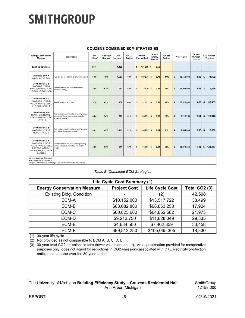
The University of Michigan Building Efficiency Study – Couzens Residential Hall SmithGroup Ann Arbor, Michigan 12158.000
REPORT - 46- 02/19/2021
Table B: Combined ECM Strategies
Life Cycle Cost Summary (1)
Energy Conservation Measure Project Cost Life Cycle Cost Total CO2 (3) Existing Bldg. Condition - (2) 42,598
ECM-A $10,152,000 $13,517,722 38,499 ECM-B $63,082,800 $66,863,258 17,924 ECM-C $60,825,600 $64,852,582 21,973 ECM-D $9,213,750 $11,828,049 29,335 ECM-E $4,684,500 $7,462,359 33,458 ECM-F $99,812,250 $105,065,305 18,330
(1) 30-year life cycle(2) Not provided as not comparable to ECM A, B, C, D, E, F.(3) 30-year total CO2 emissions in tons (lower values are better). An approximation provided for comparative
purposes only; does not adjust for reductions in CO2 emissions associated with DTE electricity productionanticipated to occur over the 30-year period.
Energy Conservation Measure
DescriptionEUI
(kBtu/sf)% Energy Savings
CO2 (tons/year)
% CO2 Savings
Annual Energy Cost
Annual Energy Cost/SF
% Cost Savings
Project Cost Simple
Payback (Years)
CO2 Avoided (Cost/ton)
Existing Condition 98.4 - 1,420 - $ 151,956 $ 0.66 - - - -
Combined ECM-AHVAC-1A-2 , ELEC-2
"Typical" UM approach to a renovation project 58.8 40% 1,283 10% $ 169,276 $ 0.73 -11% $ 10,152,000 586 $ 74,102
Combined ECM-BHVAC-1A-2, HVAC-2,
HVAC-3, HVAC-6, ELEC-1, ELEC-2, ELEC-3, ARCH-
5
Maximize carbon reduction and provide renewable energy 32.5 67% 597 58% $ 73,429 $ 0.32 52% $ 63,082,800 803 $ 76,650
Combined ECM-CHVAC-1A-2, HVAC-2,
HVAC-3, HVAC-6, ELEC-2, ELEC-3, ARCH-5
Maximize carbon reduction 37.0 62% 732 48% $ 92,922 $ 0.40 39% $ 60,825,600 1,030 $ 88,409
Combined ECM-DHVAC-1A-2 , HVAC-2,
HVAC-3, HVAC-6, ELEC-1, ARCH-2
Balanced approach to achieve healthy carbon reduction while minimizing costs including renewable energy
45.4 54% 978 31% $ 128,372 $ 0.55 16% $ 9,213,750 391 $ 20,846
Combined ECM-EHVAC-1A-2, HVAC-2,
HVAC-3, HVAC-6
Balanced approach to achieve healthy carbon reduction while minimizing costs 50.1 49% 1,115 21% $ 148,222 $ 0.64 2% $ 4,684,500 1,255 $ 15,359
Combined ECM-FHVAC-1B-1, HVAC-2,
HVAC-3, HVAC-6, ELEC-2, ELEC-3, ARCH-1,
ARCH-2, ARCH-3, ARCH-4,ARCH-5
Maximize carbon reduction utiilizing existing campus infrastructure without renewable energy 32.9 67% 611 57% $ 75,383 $ 0.33 50% $ 99,812,250 1,303 $ 123,377
Natural Gas Rate: $3.40/McfElectricity Rate: $0.086/kWh*Project Cost based on Walbridge Cost Estimate V2 dated 12/14/2020
COUZENS COMBINED ECM STRATEGIES
The University of Michigan Building Efficiency Study – Couzens Residential Hall SmithGroup Ann Arbor, Michigan 12158.000
REPORT - 47- 02/19/2021
Conclusion There are opportunities to significantly reduce the carbon emissions of Couzens.
This study looked at options using the existing campus infrastructure and a new potential campus infrastructure. The central plant is a big undefined context to reduce energy and carbon. This study addressed some of the existing and future options under consideration for the central plant transformation. However, the timing and commitment of the transformation is still evolving. Clarity of a single compelling strategy that can be applied to other buildings has not emerged, in part because Couzens is a newly renovated building which contributed to some energy improvements that older buildings would not have as a baseline. The most opportune time to include efficient systems is when replacement is required. The marginal costs of improvement can have a reasonable payback period. The fact that Couzens had been recently renovated to a level comparable to meet current UM guidelines for energy and sustainability increases the payback timeline.
The combined scenarios were largely impacted by the HVAC ECM options. Scenario B that uses a centralized water source heat pump and renewable energy shows results similar to scenario F that uses a de-centralized water sourced VRF fan coils and no renewable energy. Both of these options provided the most energy and carbon reductions.
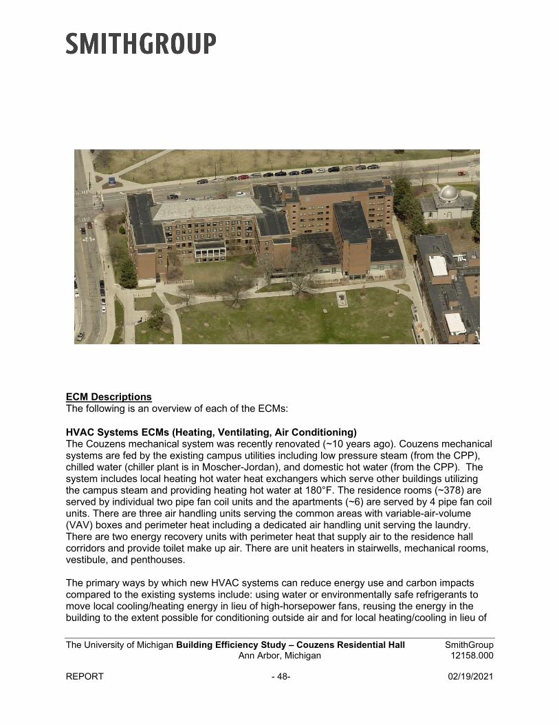
The University of Michigan Building Efficiency Study – Couzens Residential Hall SmithGroup Ann Arbor, Michigan 12158.000
REPORT - 48- 02/19/2021
ECM Descriptions The following is an overview of each of the ECMs:
HVAC Systems ECMs (Heating, Ventilating, Air Conditioning) The Couzens mechanical system was recently renovated (~10 years ago). Couzens mechanical systems are fed by the existing campus utilities including low pressure steam (from the CPP), chilled water (chiller plant is in Moscher-Jordan), and domestic hot water (from the CPP). The system includes local heating hot water heat exchangers which serve other buildings utilizing the campus steam and providing heating hot water at 180°F. The residence rooms (~378) are served by individual two pipe fan coil units and the apartments (~6) are served by 4 pipe fan coil units. There are three air handling units serving the common areas with variable-air-volume (VAV) boxes and perimeter heat including a dedicated air handling unit serving the laundry. There are two energy recovery units with perimeter heat that supply air to the residence hall corridors and provide toilet make up air. There are unit heaters in stairwells, mechanical rooms, vestibule, and penthouses.
The primary ways by which new HVAC systems can reduce energy use and carbon impacts compared to the existing systems include: using water or environmentally safe refrigerants to move local cooling/heating energy in lieu of high-horsepower fans, reusing the energy in the building to the extent possible for conditioning outside air and for local heating/cooling in lieu of
The University of Michigan Building Efficiency Study – Couzens Residential Hall SmithGroup Ann Arbor, Michigan 12158.000
REPORT - 49- 02/19/2021
using only “new” energy sources, and relying on a low-entropy campus system approach for the building’s net heating and cooling loads.
The HVAC ECM were developed, exploring the most viable and cost-effective options currently available. Note that the first set of mechanical ECMs assume that the existing central campus plant is available to provide heating and cooling water. The second set of ECMs assume that the central plant has been updated and the plant will provide chilled water from a future campus geo-exchange district and medium temperature heating hot water from a future campus geo-exchange district (not domestic hot water) to Couzens. Costs associated with revising the central plant are not included since a separate team is studying potential revisions to the existing central plant.
Existing Campus Infrastructure HVAC- ECMs
HVAC-1A-1, Centralized Water Source Heat Pumpo This ECM is to provide a high-lift heat pump (in the basement) to serve the
building’s heating needs in low to moderate heating conditions.o The existing fan coils, air handling units, energy recovery units, perimeter heat,
and terminal units would remain.o Assumed 80% of peak heating load would be served by high lift heat pump
boosting 58°F CHWR to 140°F, the remaining 20% of peak capacity would beserved by the existing heating hot water heat exchangers at 180°F HHW which isserved by the campus steam.
o Cooling to remain from campus CHW plant.o This ECM assumes chilled water from the central plant is being utilized by other
buildings throughout the heating season. The exact load and chilled wateravailability would need to be further investigated and confirmed.
o Most of the work would be in unoccupied spaces (basement/mechanical rooms).o There would be tie ins to the existing chilled water and heating hot water systems
located in the basement. The location of the basement provides an opportunityfor minimal impact to the shutdown of utilities.
o This option provides an eco-friendly alternative because it removes heat from thechilled water plant transferring it to meet the building heating needs. This helpsthe central chilled water plant create a cooling resource that other buildings onthe central system can use. This system also reduces the demand on the centralsteam plant.
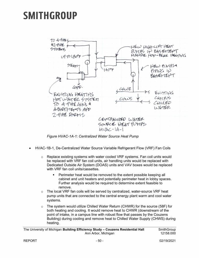
The University of Michigan Building Efficiency Study – Couzens Residential Hall SmithGroup Ann Arbor, Michigan 12158.000
REPORT - 50 - 02/19/2021
Figure HVAC-1A-1: Centralized Water Source Heat Pump
HVAC-1B-1, De-Centralized Water Source Variable Refrigerant Flow (VRF) Fan Coils
o Replace existing systems with water cooled VRF systems. Fan coil units wouldbe replaced with VRF fan coil units, air handling units would be replaced withDedicated Outside Air System (DOAS) units and VAV boxes would be replacedwith VRF fan coil units/cassettes.
Perimeter heat would be removed to the extent possible keeping allcabinet and unit heaters and potentially perimeter heat in lobby spaces.Further analysis would be required to determine extent feasible toremove.
o The local VRF fan coils will be served by centralized, water-source VRF heatpump units that are connected to the central energy plant warm and cool watersystems.
o The system would utilize Chilled Water Return (CHWR) for the source (58F) forboth heating and cooling. It would remove heat to CHWR (downstream of thepoint of intake, in a campus line with robust flow that passes by the CouzensBuilding) during cooling and remove heat to Chilled Water Supply (CHWS) duringheating.
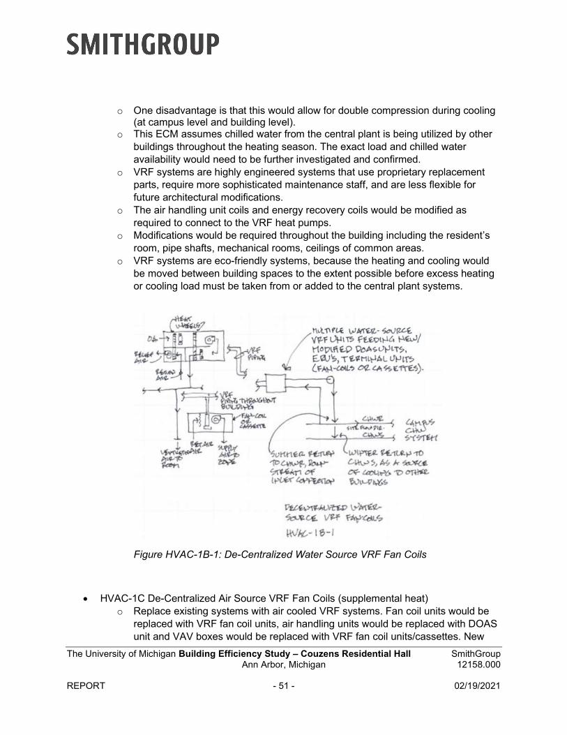
The University of Michigan Building Efficiency Study – Couzens Residential Hall SmithGroup Ann Arbor, Michigan 12158.000
REPORT - 51 - 02/19/2021
o One disadvantage is that this would allow for double compression during cooling(at campus level and building level).
o This ECM assumes chilled water from the central plant is being utilized by otherbuildings throughout the heating season. The exact load and chilled wateravailability would need to be further investigated and confirmed.
o VRF systems are highly engineered systems that use proprietary replacementparts, require more sophisticated maintenance staff, and are less flexible forfuture architectural modifications.
o The air handling unit coils and energy recovery coils would be modified asrequired to connect to the VRF heat pumps.
o Modifications would be required throughout the building including the resident’sroom, pipe shafts, mechanical rooms, ceilings of common areas.
o VRF systems are eco-friendly systems, because the heating and cooling wouldbe moved between building spaces to the extent possible before excess heatingor cooling load must be taken from or added to the central plant systems.
Figure HVAC-1B-1: De-Centralized Water Source VRF Fan Coils
HVAC-1C De-Centralized Air Source VRF Fan Coils (supplemental heat)o Replace existing systems with air cooled VRF systems. Fan coil units would be
replaced with VRF fan coil units, air handling units would be replaced with DOASunit and VAV boxes would be replaced with VRF fan coil units/cassettes. New
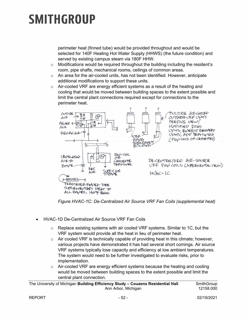
The University of Michigan Building Efficiency Study – Couzens Residential Hall SmithGroup Ann Arbor, Michigan 12158.000
REPORT - 52 - 02/19/2021
perimeter heat (finned tube) would be provided throughout and would be selected for 140F Heating Hot Water Supply (HHWS) (the future condition) and served by existing campus steam via 180F HHW.
o Modifications would be required throughout the building including the resident’sroom, pipe shafts, mechanical rooms, ceilings of common areas.
o An area for the air-cooled units, has not been identified. However, anticipateadditional modifications to support these units.
o Air-cooled VRF are energy efficient systems as a result of the heating andcooling that would be moved between building spaces to the extent possible andlimit the central plant connections required except for connections to theperimeter heat.
Figure HVAC-1C: De-Centralized Air Source VRF Fan Coils (supplemental heat)
HVAC-1D De-Centralized Air Source VRF Fan Coils
o Replace existing systems with air cooled VRF systems. Similar to 1C, but theVRF system would provide all the heat in lieu of perimeter heat.
o Air cooled VRF is technically capable of providing heat in this climate; however,various projects have demonstrated it has had several short comings. Air sourceVRF systems typically lose capacity and efficiency at low ambient temperatures.The system would need to be further investigated to evaluate risks, prior toimplementation.
o Air-cooled VRF are energy efficient systems because the heating and coolingwould be moved between building spaces to the extent possible and limit thecentral plant connection.
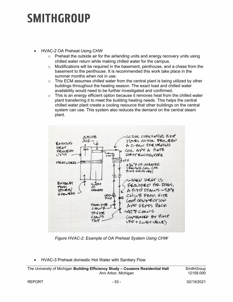
The University of Michigan Building Efficiency Study – Couzens Residential Hall SmithGroup Ann Arbor, Michigan 12158.000
REPORT - 53 - 02/19/2021
HVAC-2 OA Preheat Using CHWo Preheat the outside air for the airlanding units and energy recovery units using
chilled water return while making chilled water for the campus.o Modifications will be required in the basement, penthouse, and a chase from the
basement to the penthouse. It is recommended this work take place in thesummer months when not in use.
o This ECM assumes chilled water from the central plant is being utilized by otherbuildings throughout the heating season. The exact load and chilled wateravailability would need to be further investigated and confirmed.
o This is an energy efficient option because it removes heat from the chilled waterplant transferring it to meet the building heating needs. This helps the centralchilled water plant create a cooling resource that other buildings on the centralsystem can use. This system also reduces the demand on the central steamplant.
Figure HVAC-2: Example of OA Preheat System Using CHW
HVAC-3 Preheat domestic Hot Water with Sanitary Flow
The University of Michigan Building Efficiency Study – Couzens Residential Hall SmithGroup Ann Arbor, Michigan 12158.000
REPORT - 54 - 02/19/2021
o ECM Not applicable when using campus domestic hot water
HVAC-4 De-Centralized Ground Source Heat Pumpso Provide geothermal wells and heat pumps for heating and cooling of residential
rooms. There would be a tie into central utilities to reject heat as required.o Replace fan coil units with water source heat pumps. Existing air handling units
and downstream devices would remain.o Modifications would be required throughout the building including the resident’s
rooms, mechanical rooms, and site.o This was not taken to the next level because it is being investigated under
another study at a campus level.
HVAC-5 Not Used
HVAC-6 Residential Room Space Temperature Set-Backo Use existing lighting occupancy sensors to set back space temperatures in
residential rooms.o Tie in occupancy sensors to existing Siemens controllers.o Modifications would be limited to wiring within residential rooms.o A potential shortcoming for this option is that the system could react as if the
space was unoccupied while the occupants were not moving (i.e. sleeping).There are options such as manual overrides to overcome this issue, but theycome with other limitations. Further discussion would be required beforeinstallation.
o This is an energy efficient option because it reduces the HVAC load whenspaces are unoccupied.
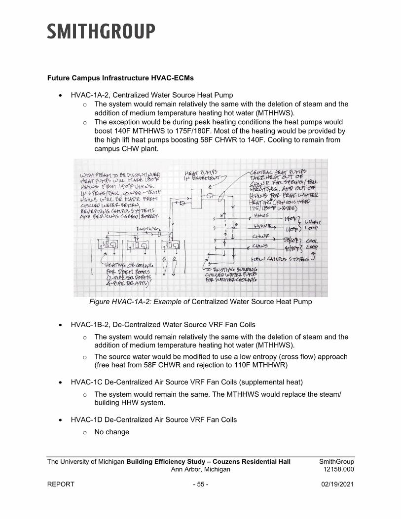
The University of Michigan Building Efficiency Study – Couzens Residential Hall SmithGroup Ann Arbor, Michigan 12158.000
REPORT - 55 - 02/19/2021
Future Campus Infrastructure HVAC-ECMs
HVAC-1A-2, Centralized Water Source Heat Pumpo The system would remain relatively the same with the deletion of steam and the
addition of medium temperature heating hot water (MTHHWS).o The exception would be during peak heating conditions the heat pumps would
boost 140F MTHHWS to 175F/180F. Most of the heating would be provided bythe high lift heat pumps boosting 58F CHWR to 140F. Cooling to remain fromcampus CHW plant.
Figure HVAC-1A-2: Example of Centralized Water Source Heat Pump
HVAC-1B-2, De-Centralized Water Source VRF Fan Coils
o The system would remain relatively the same with the deletion of steam and theaddition of medium temperature heating hot water (MTHHWS).
o The source water would be modified to use a low entropy (cross flow) approach(free heat from 58F CHWR and rejection to 110F MTHHWR)
HVAC-1C De-Centralized Air Source VRF Fan Coils (supplemental heat)
o The system would remain the same. The MTHHWS would replace the steam/building HHW system.
HVAC-1D De-Centralized Air Source VRF Fan Coils
o No change
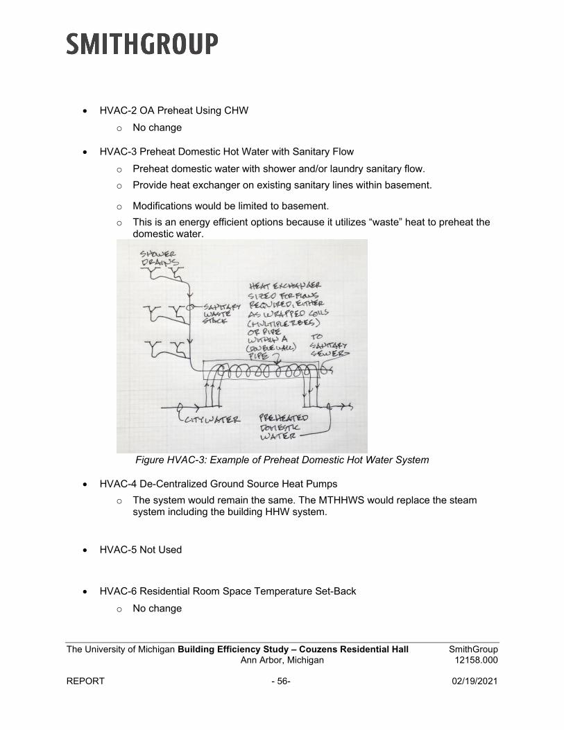
The University of Michigan Building Efficiency Study – Couzens Residential Hall SmithGroup Ann Arbor, Michigan 12158.000
REPORT - 56- 02/19/2021
HVAC-2 OA Preheat Using CHW
o No change
HVAC-3 Preheat Domestic Hot Water with Sanitary Flow
o Preheat domestic water with shower and/or laundry sanitary flow.
o Provide heat exchanger on existing sanitary lines within basement.
o Modifications would be limited to basement.
o This is an energy efficient options because it utilizes “waste” heat to preheat thedomestic water.
Figure HVAC-3: Example of Preheat Domestic Hot Water System
HVAC-4 De-Centralized Ground Source Heat Pumps
o The system would remain the same. The MTHHWS would replace the steamsystem including the building HHW system.
HVAC-5 Not Used
HVAC-6 Residential Room Space Temperature Set-Back
o No change
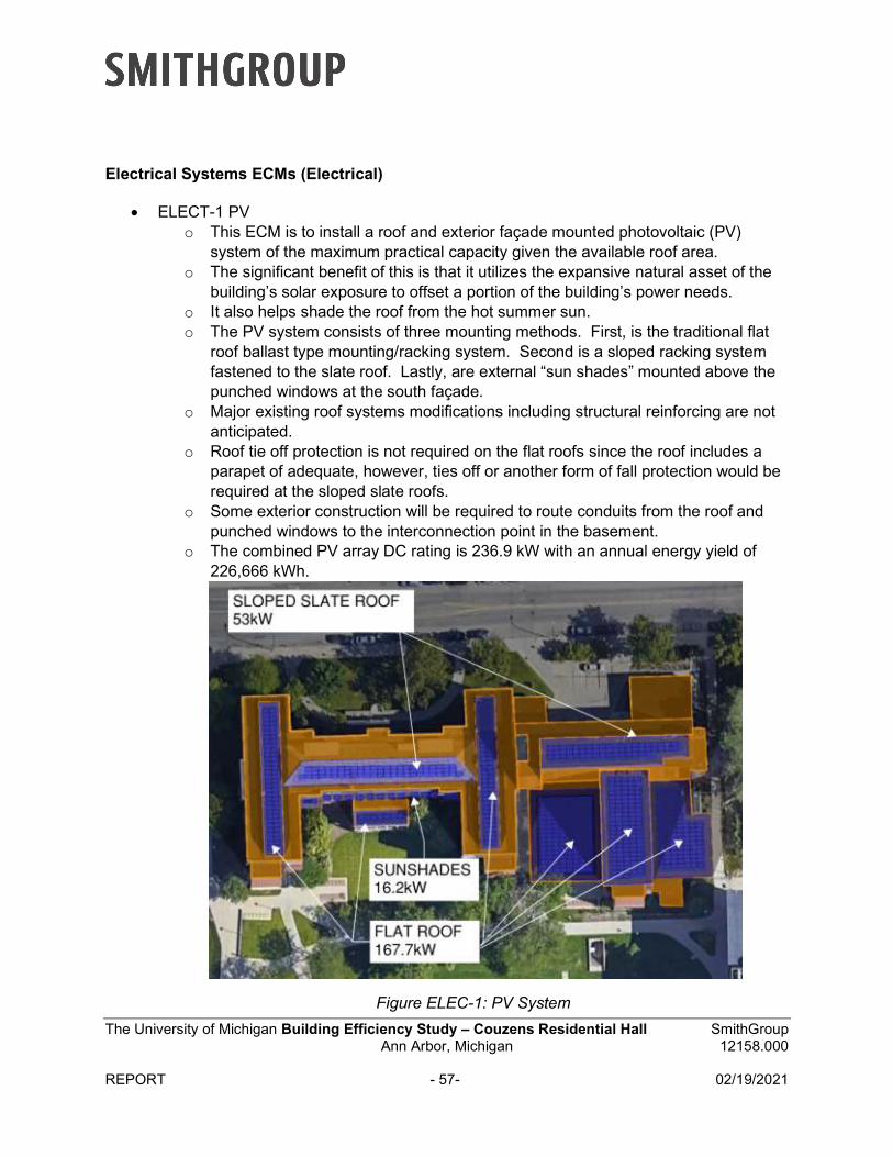
The University of Michigan Building Efficiency Study – Couzens Residential Hall SmithGroup Ann Arbor, Michigan 12158.000
REPORT - 57- 02/19/2021
Electrical Systems ECMs (Electrical)
ELECT-1 PVo This ECM is to install a roof and exterior façade mounted photovoltaic (PV)
system of the maximum practical capacity given the available roof area.o The significant benefit of this is that it utilizes the expansive natural asset of the
building’s solar exposure to offset a portion of the building’s power needs.o It also helps shade the roof from the hot summer sun.o The PV system consists of three mounting methods. First, is the traditional flat
roof ballast type mounting/racking system. Second is a sloped racking systemfastened to the slate roof. Lastly, are external “sun shades” mounted above thepunched windows at the south façade.
o Major existing roof systems modifications including structural reinforcing are notanticipated.
o Roof tie off protection is not required on the flat roofs since the roof includes aparapet of adequate, however, ties off or another form of fall protection would berequired at the sloped slate roofs.
o Some exterior construction will be required to route conduits from the roof andpunched windows to the interconnection point in the basement.
o The combined PV array DC rating is 236.9 kW with an annual energy yield of226,666 kWh.
Figure ELEC-1: PV System
The University of Michigan Building Efficiency Study – Couzens Residential Hall SmithGroup Ann Arbor, Michigan 12158.000
REPORT - 58- 02/19/2021
ELECT-2 Lighting Efficiency Upgradeo This ECM is to replace existing fluorescent light fixtures with highly efficient LED
(light emitting diodes) sources. The upgrades would be a one-for-one fixturereplacement. Fixture quantity and distribution would remain as is.
o Most of the building does have automatic controls. However, there is anopportunity to modify the controls in three ways. One is to add auto off controlswhere currently not present. Two is to add daylight harvesting controls wherethere is access to natural daylight. And three is to modify the current time of dayscheduled controls to allow lighting fixtures to turn off during period of vacancy.
ELECT-3 Submetering
o Given the function and use of the facility, the energy consumption is heavilyinfluenced by student occupant energy habits. Raising occupant awarenessabout energy use and carbon could potentially help to increase energy savingsand lower carbon production.
o Submetering of energy use and load types will enable the university staff andstudents to understand their impact on energy and carbon footprint at a granularlevel.
o There are two options of submetering. Option one is to replace existingpanelboards with “title 24” style panels premanufactured for load segregation andsubmetering load classifications (e.g., lighting, HVAC, plugs and appliances).This option involves replacing 40 panelboards. Option two is to submeter loadsby floor only. This option includes leaving the existing panelboards intact andonly adding appropriate submeters per floor. This would include adding 53submeters. In either option, IP-based remote monitoring and connection to thebuilding management system (BMS) is included.
o Option two was priced as the basis of design.
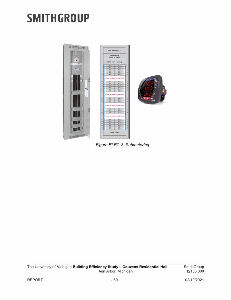
The University of Michigan Building Efficiency Study – Couzens Residential Hall SmithGroup Ann Arbor, Michigan 12158.000
REPORT - 59- 02/19/2021
Figure ELEC-3: Submetering

The University of Michigan Building Efficiency Study – Couzens Residential Hall SmithGroup Ann Arbor, Michigan 12158.000
REPORT - 60 - 02/19/2021
Arch Systems ECMs (Architecture)
ARCH-1 New High-Performance Windowso New modern fenestration systems reduce heat loss to the exterior in the winter
and will reduce the amount of heat entering the building in the summer.o Replace the existing curtain wall and window systems with a system that
exceeds the performance of typical energy efficient systems. The existingsystems appear to be common for the time of the previous renovation, completedin 2011, with a single thermal break and insulated glazing units.
Performance of new systems are based on triple glazed units with argonfilled cavities and two Low-E coatings. Framing system are based onultra-thermal performance systems that include thermal breaks greaterthan ¼”.
Punched Windowso U-Factor: 0.34o SHGC:0.26o VLT: 47%
First Floor Curtain Wallo U-Factor: 0.31o SHGC: 0.25o VLT: 56%
o Wall construction near each window will need to be investigated and repaired toallow for the attachment of the new system. This may require selective demolitionat each window opening.
o Selective demolition of masonry veneer will be required to allow for newfenestration to tie into the air and water plane of existing assembly.
o Interior finishes near the construction area will likely need to be repaired andcleaned.
Figure ARCH-1: Example of High-Performance Window System
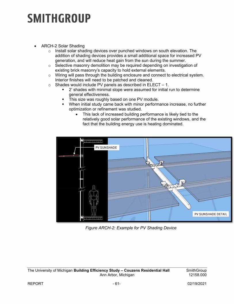
The University of Michigan Building Efficiency Study – Couzens Residential Hall SmithGroup Ann Arbor, Michigan 12158.000
REPORT - 61- 02/19/2021
ARCH-2 Solar Shadingo Install solar shading devices over punched windows on south elevation. The
addition of shading devices provides a small additional space for increased PVgeneration, and will reduce heat gain from the sun during the summer.
o Selective masonry demolition may be required depending on investigation ofexisting brick masonry’s capacity to hold external elements.
o Wiring will pass through the building enclosure and connect to electrical system.Interior finishes will need to be patched and cleaned.
o Shades would include PV panels as described in ELECT – 1. 2’ shades with minimal slope were assumed for initial run to determine
general effectiveness. This size was roughly based on one PV module. When initial study came back with minor performance increase, no further
optimization or refinement was studied. This lack of increased building performance is likely tied to the
relatively good solar performance of the existing windows, and thefact that the building energy use is heating dominated.
Figure ARCH-2: Example for PV Shading Device
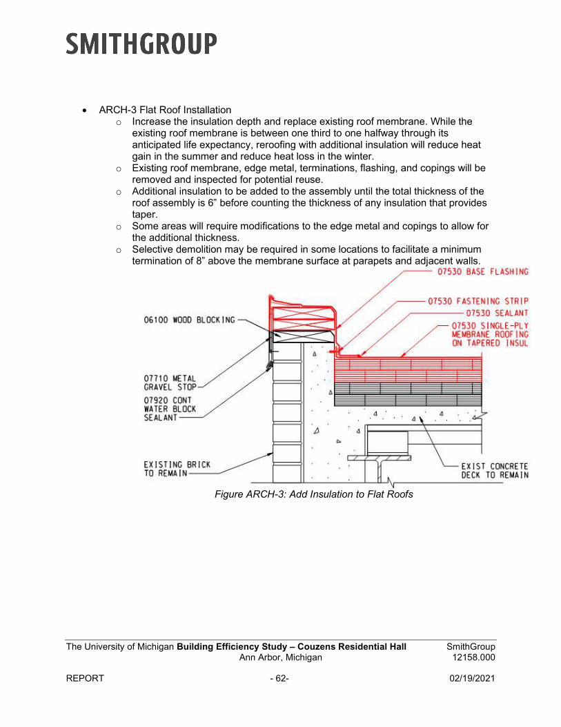
The University of Michigan Building Efficiency Study – Couzens Residential Hall SmithGroup Ann Arbor, Michigan 12158.000
REPORT - 62- 02/19/2021
ARCH-3 Flat Roof Installationo Increase the insulation depth and replace existing roof membrane. While the
existing roof membrane is between one third to one halfway through itsanticipated life expectancy, reroofing with additional insulation will reduce heatgain in the summer and reduce heat loss in the winter.
o Existing roof membrane, edge metal, terminations, flashing, and copings will beremoved and inspected for potential reuse.
o Additional insulation to be added to the assembly until the total thickness of theroof assembly is 6” before counting the thickness of any insulation that providestaper.
o Some areas will require modifications to the edge metal and copings to allow forthe additional thickness.
o Selective demolition may be required in some locations to facilitate a minimumtermination of 8” above the membrane surface at parapets and adjacent walls.
Figure ARCH-3: Add Insulation to Flat Roofs
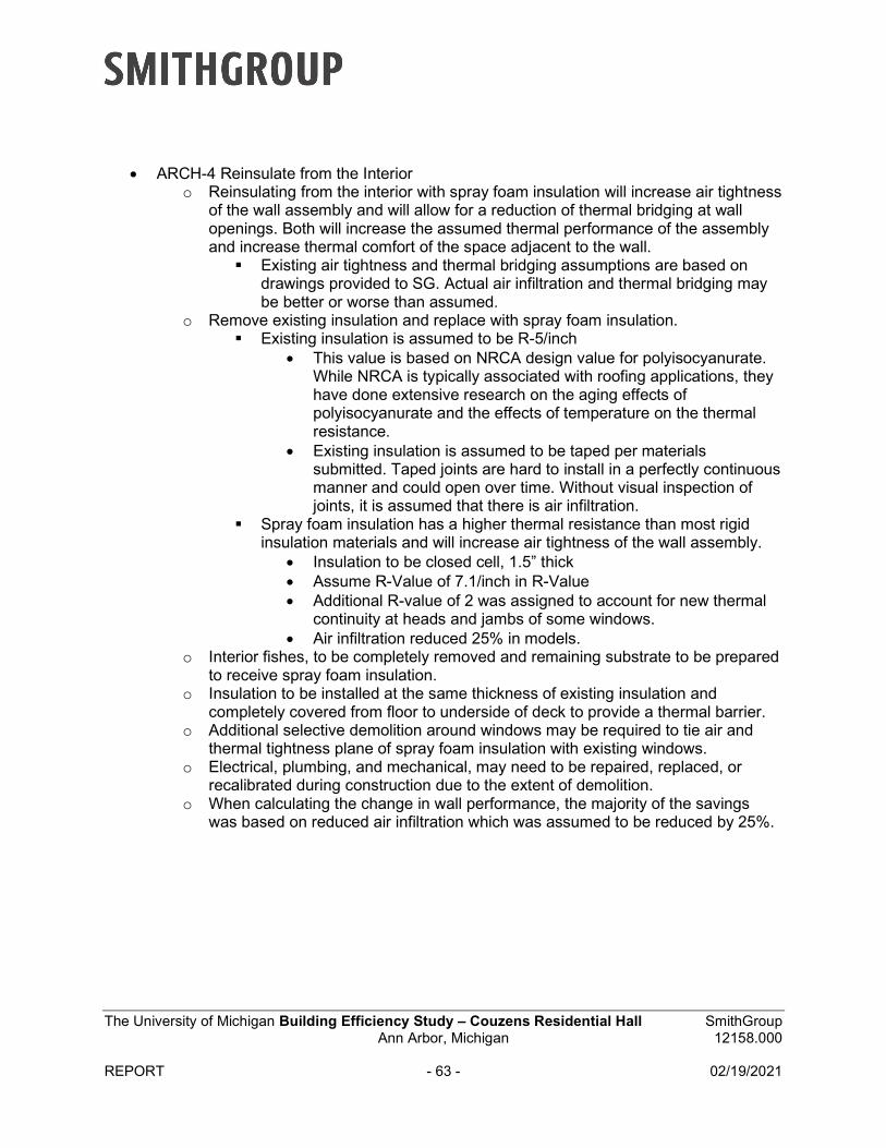
The University of Michigan Building Efficiency Study – Couzens Residential Hall SmithGroup Ann Arbor, Michigan 12158.000
REPORT - 63 - 02/19/2021
ARCH-4 Reinsulate from the Interioro Reinsulating from the interior with spray foam insulation will increase air tightness
of the wall assembly and will allow for a reduction of thermal bridging at wallopenings. Both will increase the assumed thermal performance of the assemblyand increase thermal comfort of the space adjacent to the wall.
Existing air tightness and thermal bridging assumptions are based ondrawings provided to SG. Actual air infiltration and thermal bridging maybe better or worse than assumed.
o Remove existing insulation and replace with spray foam insulation. Existing insulation is assumed to be R-5/inch
This value is based on NRCA design value for polyisocyanurate.While NRCA is typically associated with roofing applications, theyhave done extensive research on the aging effects ofpolyisocyanurate and the effects of temperature on the thermalresistance.
Existing insulation is assumed to be taped per materialssubmitted. Taped joints are hard to install in a perfectly continuousmanner and could open over time. Without visual inspection ofjoints, it is assumed that there is air infiltration.
Spray foam insulation has a higher thermal resistance than most rigidinsulation materials and will increase air tightness of the wall assembly.
Insulation to be closed cell, 1.5” thick Assume R-Value of 7.1/inch in R-Value Additional R-value of 2 was assigned to account for new thermal
continuity at heads and jambs of some windows. Air infiltration reduced 25% in models.
o Interior fishes, to be completely removed and remaining substrate to be preparedto receive spray foam insulation.
o Insulation to be installed at the same thickness of existing insulation andcompletely covered from floor to underside of deck to provide a thermal barrier.
o Additional selective demolition around windows may be required to tie air andthermal tightness plane of spray foam insulation with existing windows.
o Electrical, plumbing, and mechanical, may need to be repaired, replaced, orrecalibrated during construction due to the extent of demolition.
o When calculating the change in wall performance, the majority of the savingswas based on reduced air infiltration which was assumed to be reduced by 25%.
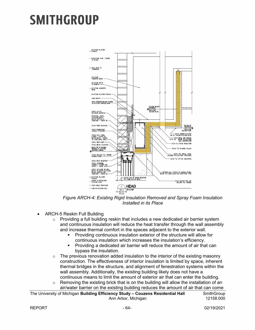
The University of Michigan Building Efficiency Study – Couzens Residential Hall SmithGroup Ann Arbor, Michigan 12158.000
REPORT - 64- 02/19/2021
Figure ARCH-4: Existing Rigid Insulation Removed and Spray Foam Insulation Installed in its Place
ARCH-5 Reskin Full Buildingo Providing a full building reskin that includes a new dedicated air barrier system
and continuous insulation will reduce the heat transfer through the wall assemblyand increase thermal comfort in the spaces adjacent to the exterior wall.
Providing continuous insulation exterior of the structure will allow forcontinuous insulation which increases the insulation’s efficiency.
Providing a dedicated air barrier will reduce the amount of air that canbypass the insulation.
o The previous renovation added insulation to the interior of the existing masonryconstruction. The effectiveness of interior insulation is limited by space, inherentthermal bridges in the structure, and alignment of fenestration systems within thewall assembly. Additionally, the existing building likely does not have acontinuous means to limit the amount of exterior air that can enter the building.
o Removing the existing brick that is on the building will allow the installation of anair/water barrier on the existing building reduces the amount of air that can come
The University of Michigan Building Efficiency Study – Couzens Residential Hall SmithGroup Ann Arbor, Michigan 12158.000
REPORT - 65- 02/19/2021
in and out of the building. This not only helps increase occupant conform but also allows the mechanical system can heat and cool spaces more efficiently. Additionally, an air/water barrier can reduce water infiltration into the building and reduce the risk of condensation in the wither. Both functions will help protect the existing structure from long term water damage.
After the removal of existing brick has completed, prepare existingbuilding substrate to receive a fluid applied air/water barrier assembly.This assembly includes new flashings, and transitions to existingfenestration, roofing, and foundation waterproofing.
o Removing the brick will also allow new insulation to be installed. Adding newinsulation on the exterior of the building will increase the energy efficiency of theexterior wall. This will also make the spaces within the building that are locatedon an exterior wall more comfortable to the users by increasing the radianttemperature of the exterior wall surfaces.
Install three inches of extruded polystyrene ultra and a nominal two-inchair space.
o During demolition of the exterior wall, it is also recommended that the interiorinsulation that was installed during the previous renovation be removed. This willhave a significant impact on the ability to occupy the space during demolition andconstruction. The removal of the existing insulation will reduce the risk ofcondensation within the wall assembly and allow the air/water/vapor controllayers to be conditioned by the interior space.
o All major systems within the exterior wall will likely be impacted by the ECMincluding the Structure, Mechanical, Electrical, Plumbing. While not all systemswill be impacted the same, the change to the wall is significant, and in fieldconditions may require the alteration, moving, or recalibrating of these systems.
o In addition to the above grade structural improvements that may be required,there will be structural impacts to the foundation. This will be based on the weightand attachment system of the new exterior wall veneer.
o Roofing and waterproofing will require some modifications to allow the new airand water barrier to integrate with the existing systems. Air and water tightnessare critical to the longevity and efficiency of a building, so new systems should beintegrated with the existing.
o Due to the extensive construction from the exterior, some site work will berequired to remedy any damage from the construction.
o This EMC has a lot of unknown variables including the condition of the existingstructure and interior part of the existing wall.
o During demolition of existing masonry, brick should be removed in a manner tosalvage and reuse as much of the existing brick as possible. Photographiclogging of existing brick patterns and general coloration should take place prior toany demolition.
o Reinstall brick to replicate patterning and general coloration of the originalbuilding. Patterning on the existing building to be implemented on both theoriginal building and additions, to unify the appearance of the masonry.
o Reinstall interior finishes.
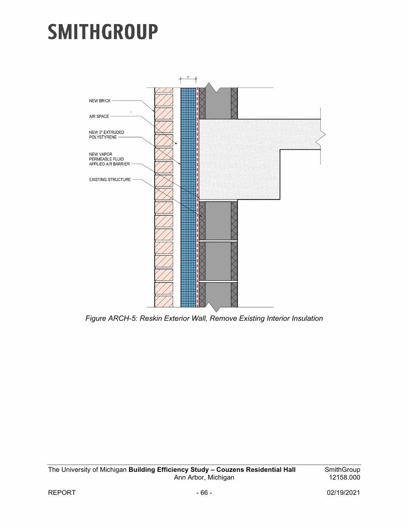
The University of Michigan Building Efficiency Study – Couzens Residential Hall SmithGroup Ann Arbor, Michigan 12158.000
REPORT - 66 - 02/19/2021
Figure ARCH-5: Reskin Exterior Wall, Remove Existing Interior Insulation
”
The University of Michigan Building Efficiency Study – Couzens Residential Hall SmithGroup Ann Arbor, Michigan 12158.000
REPORT - 67 - 02/19/2021
Six scenarios were then developed where various ECMs were combined to maximize energy use reduction and reduce carbon impacts:
Combined ECMs
The combined ECMs are provided with the future central utility plant
ECM Scenario A is the combination of the following components HVAC 1A -2– Centralized Water Source Heat Pump ELEC 2 – Lighting Efficiency UpgradeThis combined set of ECM will provide energy and CO2 reductions from the existingconditions of 40% energy savings; CO2 reduction of 137 tons/year; Energy Use Intensity(EUI) of /sf 58.8 kBTU/sf a saving of 39.6 kBTU/sf per year and total energy cost increaseper year of $17,320.
ECM Scenario B is the combination of the following components HVAC 1A-2 – Centralized Water Source Heat Pump HVAC 2 – OA Preheat Using CHW HVAC 3 – Preheating Domestic Hot Water with Sanitary Flow HVAC 6 – Residential Room Space Temperature Set-Back ELEC 1 – PV ELEC 2 – Lighting Efficiency Upgrade ELEC 3 – Submetering ARCH 5 – Remove Interior Insulation and Reskin BrickThis combined set of ECM will provide energy and CO2 reductions from the existingconditions of 67% energy savings; CO2 reduction of 822 tons/year; Energy Use Intensity(EUI) of /sf 32.5 kBTU/sf a saving of 65.9 kBTU/sf per year and total energy cost saving peryear of $78,527.
ECM Scenario C is the combination of the following components HVAC 1A -2– Centralized Water Source Heat Pump HVAC 2 – OA Preheat Using CHW HVAC 3 – Preheating Domestic Hot Water with Sanitary Flow HVAC 6 – Residential Rm Space Temp Set-Back ELEC 2 – Lighting Efficiency Upgrade ELEC 3 – Submetering ARCH 5 – Remove Interior Insulation and Reskin Brick This ECM combination is the same as ECM B but with no PV.This combined set of ECM will provide energy and CO2 reductions from the existingconditions of 62% energy savings; CO2 reduction of 688 tons/year; Energy Use Intensity(EUI) of /sf 37.0 kBTU/sf a saving of 61.3 kBTU/sf per year and total energy cost saving peryear of $59,034.
The University of Michigan Building Efficiency Study – Couzens Residential Hall SmithGroup Ann Arbor, Michigan 12158.000
REPORT - 68- 02/19/2021
ECM Scenario D is the combination of the following components HVAC 1A -1– Centralized Water Source Heat Pump HVAC 2 – OA Preheat Using CHW HVAC 3 – Preheating Domestic Hot Water with Sanitary Flow HVAC 6 – Residential Room Space Temperature Set-Back ELEC 1 – PV ARCH 2 – Solar ShadingThis combined set of ECM will provide energy and CO2 reductions from the existingconditions of 54% energy savings; CO2 reduction of 422 tons/year; Energy Use Intensity(EUI) of /sf 45.4 kBTU/sf a saving of 53.0 kBTU/sf per year and total energy cost saving peryear of $23,583.
ECM Scenario E is the combination of the following components HVAC 1A -1– Centralized Water Source Heat Pump HVAC 2 – OA Preheat Using CHW HVAC 3 – Preheating Domestic Hot Water with Sanitary Flow HVAC 6 – Residential Room Space Temperature Set-Back This ECM combination is the same as ECM D but with no PVThis combined set of ECM will provide energy and CO2 reductions from the existingconditions of 49% energy savings; CO2 reduction of 305 tons/year; Energy Use Intensity(EUI) of /sf 50.1 kBTU/sf a saving of 48.3 kBTU/sf per year and total energy cost saving peryear of $3,733.
ECM Scenario F is the combination of the following components HVAC 1B -1– De-Centralized Water Source VRF Fan Coils HVAC 2 – OA Preheat Using CHW HVAC 3 – Preheating Domestic Hot Water with Sanitary Flow HVAC 6 – Residential Room Space Temperature Set-Back ELEC 1 – PV ELEC 2 – Lighting Efficiency Upgrade ELEC 3 – Submetering ARCH 1 – New High-Performance windows ARCH 2 – Solar Shading ARCH 3 – Flat Roof Insulation ARCH 4 – Reinsulate from Interior ARCH 5 – Remove Interior Insulation and Reskin BrickThis combined set of ECM will provide energy and CO2 reductions from the existingconditions of 67% energy savings; CO2 reduction of 809 tons/year; Energy Use Intensity(EUI) of /sf 32.9 kBTU/sf a saving of 65.5 kBTU/sf per year and total energy cost saving peryear of $76,573.
The University of Michigan Building Efficiency Study – Couzens Residential Hall SmithGroup Ann Arbor, Michigan 12158.000
REPORT - 69 - 02/19/2021
Opinion of Probable Costs This study calculates simple payback in years as the difference between the Project Cost divided by the Annual Energy Cost savings. To determine the Project Cost, the team sought to estimate the total cost of the project. In Exhibit 6 – Costs Analysis, the Opinion of Probable Cost (OPC) is an estimate of the construction cost. Construction cost is the amount paid to a contractor (i.e., General Contractor or Construction Manager) to build the project, including the material costs, the labor costs, and the contractor's overhead & profit. Also, because this study seeks to estimate the construction cost for a future project, an allowance was included for material & labor escalation. Given the preliminary nature of this study, a design contingency was included. As noted above, in addition to Construction Cost, there are other expenses that would be necessary to complete any of these potential ECM projects. These additional expenses include things like "Related Construction" (e.g., new/revised utility and City connections, etc.), Owner's contingencies (e.g., Construction Contingency, etc.), professional fees, and miscellaneous expenses. Based on experience with previous projects, the study assumes that other expenses would be 35% of the estimated construction costs. This 1.35 factor included construction contingency, which is why the OPC notes that it contains 0% for construction contingency.
The opinion of probable costs may be perceived as high when considering a specific ECM or even a combined ECM. However, the detailed estimate included in the appendix show the extent of construction work that is required for each ECM and the combined ECM scenarios. It should also be noted that the simple paybacks provided here-in assume the existing system(s) do not need to be replaced. This produces long simple paybacks. A comparative example would be replacing your home furnace when not broken solely for the purpose of gaining the benefit of improved energy efficiency. However, during a major renovation, the simple payback would be calculated based upon the cost difference to install a more energy-efficient system verses a system that just meets current energy code requirements, resulting in shorter simple paybacks. The opinion of cost detail includes scope of work beyond just the direct components of the ECM. Other building infrastructure and existing conditions will be affected by the work required to implement the ECM. This includes structural upgrades, roofing repair or replacement, reworking or replacing mechanical, electrical, plumbing components, and replacing interior finishes.
It is also important to highlight what is not included in the project's costs proposed by this study:
Any improvements beyond those described in the study.
Escalation beyond the two years that was included in the estimate. Additional escalationmay be appropriate depending on the timeframe for implementation.
Phasing and/or temporarily other measures to facilitate the continued use andoccupancy of the building during construction.
Any costs to temporally relocate the building occupants, furniture, or equipment.
Metering and monitoring beyond what is typical for a comparable UM building.

The University of Michigan Building Efficiency Study – Couzens Residential Hall SmithGroup Ann Arbor, Michigan 12158.000
REPORT - 70 - 02/19/2021
The below tables summarize the Project Cost and Simple Payback for the ECMs listed in the above Scope section. This table includes all the individual ECMs and combined ECM’s and ranks them in terms of the cost per ton of carbon avoided.
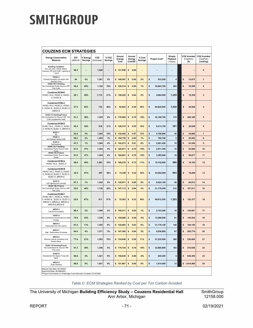
The University of Michigan Building Efficiency Study – Couzens Residential Hall SmithGroup Ann Arbor, Michigan 12158.000
REPORT - 71 - 02/19/2021
Table C: ECM Strategies Ranked by Cost per Ton Carbon Avoided
Energy Conservation Measure
EUI (kBtu/sf)
% Energy Savings
CO2 (tons/year)
% CO2 Savings
Annual Energy
Cost
Annual Energy Cost/SF
% Cost Savings
Project Cost* Simple
Payback (Years)
CO2 Avoided (Cost/ton)
($)
CO2 Avoided (Cost/ton)(ranking)
Existing ConditionFan coil units, AHUS, ERUs,
Campus LPS and CHW, Lighting at 1 W/sf
98.4 - 1,420 - $ 151,956 $ 0.66 - - - - 0
HVAC-3Preheat domestic hot water with
Sanitary Flow94 4% 1,381 3% $ 149,547 $ 0.65 2% $ 533,250 4 $ 13,673 1
HVAC-1B-1 ExistingDe-Centralized Water Source VRF
Fan Coils54.4 45% 1,152 19% $ 150,314 $ 0.65 1% $ 30,863,700 205 $ 15,359 2
Combined ECM-EHVAC-1A-2, HVAC-2, HVAC-
3, HVAC-650.1 49% 1,115 21% $ 148,222 $ 0.64 2% $ 4,684,500 1,255 $ 15,359 3
Combined ECM-CHVAC-1A-2, HVAC-2, HVAC-3, HVAC-6, ELEC-2, ELEC-3,
ARCH-5
37.0 62% 732 48% $ 92,922 $ 0.40 39% $ 60,825,600 1,030 $ 20,846 4
HVAC-1C Existing/FutureDe-Centralized Air Source VRF Fan
Coils (supplement heat)61.3 38% 1,355 5% $ 179,585 $ 0.78 -18% $ 32,186,700 179 $ 495,180 5
Combined ECM-DHVAC-1A-2 , HVAC-2, HVAC-3, HVAC-6, ELEC-1, ARCH-2
45.4 54% 978 31% $ 128,372 $ 0.55 16% $ 9,213,750 391 $ 20,846 6
ELEC-1PV 93.8 5% 1,285 10% $ 132,462 $ 0.57 13% $ 4,708,800 36 $ 34,880 7
HVAC-2OA Preheat Using CHW 96.2 2% 1,400 1% $ 150,730 $ 0.65 1% $ 785,700 5 $ 39,285 8
ELEC-3Submetering 97.3 1% 1,360 4% $ 142,273 $ 0.61 6% $ 2,601,450 18 $ 43,358 9
HVAC-1A-1 ExistingCentralized Water Source Heat
Pump 61.8 37% 1,364 4% $ 180,671 $ 0.78 -19% $ 2,971,350 16 $ 53,060 10
HVAC-1A-2 FutureCentralized Water Source Heat
Pump 61.6 37% 1,364 4% $ 180,901 $ 0.78 -19% $ 3,285,900 18 $ 58,677 11
Combined ECM-AHVAC-1A-2 , ELEC-2
58.8 40% 1,283 10% $ 169,276 $ 0.73 -11% $ 10,152,000 586 $ 74,102 12
Combined ECM-BHVAC-1A-2, HVAC-2, HVAC-3, HVAC-6, ELEC-1, ELEC-2,
ELEC-3, ARCH-5
32.5 67% 597 58% $ 73,429 $ 0.32 52% $ 63,082,800 803 $ 76,650 13
ELEC-2LED lighting and controls 97.3 1% 1,342 5% $ 138,971 $ 0.60 9% $ 6,623,100 48 $ 84,912 14
HVAC-1B-2 FutureDe-Centralized Water Source VRF
Fan Coils53.6 46% 1,130 20% $ 147,113 $ 0.64 3% $ 31,178,250 212 $ 107,511 15
Combined ECM-FHVAC-1B-1, HVAC-2, HVAC-3, HVAC-6, ELEC-2, ELEC-3, ARCH-1, ARCH-2, ARCH-3,
ARCH-4,ARCH-5
32.9 67% 611 57% $ 75,383 $ 0.33 50% $ 99,812,250 1,303 $ 123,377 16
ARCH-3Flat Roof Insulation 96.4 2% 1,398 2% $ 150,211 $ 0.65 1% $ 2,743,200 18 $ 124,691 17
HVAC-4De-Centralized Ground Source Heat
Pumps75.8 23% 1,330 6% $ 159,686 $ 0.69 -5% $ 13,009,950 81 $ 144,555 18
ARCH-4Reinsulate from the interior 87.4 11% 1,305 8% $ 142,893 $ 0.62 6% $ 21,176,100 148 $ 184,140 19
ARCH-1High Performance Windows 94.4 4% 1,371 3% $ 147,365 $ 0.64 3% $ 9,936,000 67 $ 202,776 20
ARCH-5Remove Interior Insulation and
Reskin Brick77.6 21% 1,203 15% $ 134,948 $ 0.58 11% $ 51,232,500 380 $ 236,094 21
HVAC-1D Existing/Future De-Centralized Air Source VRF
Fan Coils61.3 38% 1,356 5% $ 179,724 $ 0.78 -18% $ 32,680,800 182 $ 510,638 22
HVAC-6Residential Rm Space Temp Set-
Back 96.8 2% 1,421 0% $ 158,830 $ 0.69 -5% $ 645,300 4 $ 645,300 23
ARCH-2Solar Shading 98.6 0% 1,421 0% $ 151,867 $ 0.66 0% $ 1,814,400 12 $ 1,814,400 24
COUZENS ECM STRATEGIES
Natural Gas Rate: $3.40/McfElectricity Rate: $0.086/kWh*Project Cost based on Walbridge Cost Estimate V2 dated 12/15/2020

The University of Michigan Building Efficiency Study – Couzens Residential Hall SmithGroup Ann Arbor, Michigan 12158.000
REPORT - 72- 02/19/2021
Strategy Assessments The assessment of ECM combined strategies depends on the parameters chosen for decision making.
Modeled energy savings vary from a 40% reduction to a striking 67% reduction, with a net building EUI of 32.5 kBtu/sf/yr.
Modeled carbon (CO2) reduction savings vary from a 10% reduction to an impressive 58% reduction.
In terms of first cost, each of these strategies recognizes that the Couzens Residential Hall systems are at not at the end of their useful life and that the renovation would primarily be initiated to improve energy savings. Given that, the range in first cost of these strategies places the most energy-reducing and carbon-reducing strategy 600% higher in cost than that of the lowest strategy.
Schedule On average a 12-month to 14-month schedule is assumed for each ECM, including
complete building vacancy. The budget and schedule are based on all engineering being complete prior to starting
construction. The budgets are based on furniture and artwork being sheltered or moved out of building. 2 to 3 buildings could be completed concurrently with the existing local labor pool (This
would also allow for lessons learned to be included is subsequent projects). If a phased approach is utilized temporary heating and cooling provisions would be required
at additional cost not currently included in the cost models. Layout /use of building will be a factor in determining if a phased schedule should be
implemented. A phased schedule approach could lead to a 24-month construction schedule. Environmental studies need to be completed during the engineering phase. Extensive commissioning requirements may have an impact on the schedule duration. The ECM equipment availability and lead times could impact the schedule. Consideration of the site confines – some sites may be more restrictive than others – lay-
down and field offices, traffic control, material deliveries, etc. Cost of move-outs and the preparation of swing space should be considered. These are
not currently part of the cost models. Life safety upgrades are not included in the cost models.
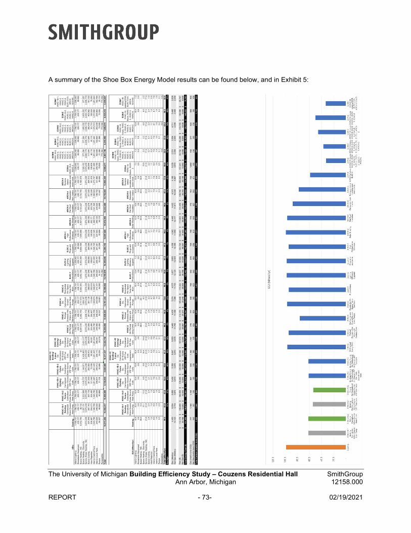
The University of Michigan Building Efficiency Study – Couzens Residential Hall SmithGroup Ann Arbor, Michigan 12158.000
REPORT - 73- 02/19/2021
A summary of the Shoe Box Energy Model results can be found below, and in Exhibit 5: kB
tuE
xist
ing
HV
AC
-1A
-1
Exi
sti
ng
Cen
tra
lize
d W
ater
Sou
rce
H
eat
Pum
p
HV
AC
-1A
-2
Fu
ture
Cen
tra
lize
d W
ate
r S
our
ce
Hea
t P
um
p
HV
AC
-1B
-1
Ex
isti
ng
De-
Ce
ntra
lized
W
ate
r S
ourc
e V
RF
Fa
n C
oils
HV
AC
-1B
-2
Fu
ture
De
-C
ent
raliz
ed
Wat
er S
ourc
e
VR
F F
an
Co
ils
HV
AC
-1C
E
xist
ing
/ F
utu
reD
e-
Cen
tra
lize
d A
ir S
our
ce
VR
F F
an
Coi
ls
(su
pple
me
nt
heat
)
HV
AC
-1D
E
xis
tin
g/
Fu
ture
De
-C
ent
raliz
ed
Air
So
urce
V
RF
Fa
n C
oils
HV
AC
-2O
A P
rehe
at
Usi
ng C
HW
HV
AC
-3
Pre
heat
D
om
est
ic H
ot
Wat
er w
ith
Sa
nita
ry F
low
HV
AC
-4
De-
Cen
tral
ized
G
roun
d S
ou
rce
He
at
Pu
mps
HV
AC
-6R
esi
dent
ial
Rm
Sp
ace
Te
mp
Se
t-B
ack
EL
EC
-1P
hot
ovol
taic
s
EL
EC
-2Li
ght
ing
Effi
cien
cy
Up
gra
de
EL
EC
-3P
lugs
and
oc
cup
ants
AR
CH
-1H
igh
Pe
rfo
rma
nce
W
indo
ws
AR
CH
-2S
olar
Sha
din
g
AR
CH
-3F
lat
Roo
f In
sula
tion
AR
CH
-4R
eins
ulat
e
fro
m I
nter
ior
AR
CH
-5R
em
ove
in
terio
r in
sula
tion
and
re
skin
bri
ck
EC
M-A
HV
AC
-1A
-2,
E
LEC
-2
EC
M-B
HV
AC
-1A
-2,
HV
AC
-2,
HV
AC
-3,
HV
AC
-6,
ELE
C-1
, E
LEC
-2,
ELE
C-3
, A
RC
H-5
EC
M-C
HV
AC
-1A
-2,
HV
AC
-2,
HV
AC
-3,
HV
AC
-6,
EL
EC
-2,
EL
EC
-3,
AR
CH
-5
EC
M-D
HV
AC
-1A
-2,
HV
AC
-2,
HV
AC
-3,
HV
AC
-6,
EL
EC
-1,
AR
CH
-2
EC
M-E
HV
AC
-1A
-2,
HV
AC
-2,
HV
AC
-3,
HV
AC
-6
EC
M-F
HV
AC
-1B
-1,
HV
AC
-2,
HV
AC
-3,
HV
AC
-6,
ELE
C-1
/2/3
, A
RC
H-
1/2
/3/4
/5
Inte
rior
Lig
htin
g1,
756
,731
1,7
56,7
31
1,7
56,
731
1,7
56,
731
1,7
56,7
31
1,7
56,
731
1,75
6,7
31
1,
756
,731
1,7
56,7
31
1,75
6,7
31
1,
756
,731
1,7
56,7
31
1,2
28,
242
1,7
56,
731
1,7
56,7
31
1,7
56,
731
1,75
6,7
31
1,
756
,73
1
1
,75
6,73
1
1,
228,
242
1,2
28,2
42
1
,228
,24
2
1
,75
6,7
31
1,
756
,731
1,2
28,2
42
Rec
epta
cle
Eq
uipm
ent
439
,177
439
,17
7
43
9,17
7
43
9,1
77
4
39,1
77
439,
177
439,
177
439
,177
439,
177
439,
177
439
,177
439
,17
7
43
9,17
7
69
,560
439
,17
7
43
9,17
7
43
9,1
77
4
39,1
77
43
9,17
7
43
9,1
77
69
,560
69,5
60
439,
177
439
,177
69,5
60
Spa
ce H
eat
ing
- N
G8,
452
,750
48,1
02
-
-
-
4
0
-
8,0
87,5
16
8
,452
,75
0
3,
717,
572
8,0
63,3
83
8
,452
,75
0
8
,83
4,39
8
8,
68
4,5
68
7
,885
,69
8
8
,50
7,07
7
8,
140,
427
6,7
33,7
56
5,1
96,
579
-
-
-
-
-
-
Spa
ce H
eat
ing
- E
lect
rici
ty-
2,2
07,1
51
2,2
22,
569
1,1
45,
737
1,1
44,6
71
2,4
28,
463
2,43
1,1
17
-
- 1,
064,
167
-
-
-
-
-
-
-
-
-
2,
326,
152
377
,284
377
,28
4
1
,00
5,2
52
1,
005
,252
377
,28
7
S
ervi
ce W
ate
r H
eatin
g -
NG
3,6
70,2
38
3
,670
,23
8
3
,67
0,23
8
3,
67
0,2
38
3
,670
,23
8
3
,67
0,23
8
3,
670,
238
3,6
70,2
38
2
,936
,17
9
3,
670,
238
3,6
70,2
38
3
,670
,23
8
3
,67
0,23
8
3,
67
0,2
38
3
,670
,23
8
3
,67
0,23
8
3,
670,
238
3,6
70,2
38
3,6
70,
238
3,67
0,2
38
2,
936
,179
2,9
36,1
79
2,9
36,
179
2,9
36,1
79
2
,936
,17
9
S
pace
Co
olin
g3
97,0
49
3
97,1
40
397,
119
361,
300
283
,08
3
28
8,47
3
29
0,6
75
3
97,0
99
39
7,04
9
38
1,1
30
3
98,6
21
3
97,0
49
366,
086
364
,689
350
,31
0
38
9,18
5
39
0,2
78
3
77,3
00
36
4,51
3
36
6,0
44
1
17,6
44
1
17,6
44
395,
400
403
,062
161
,15
0
Hea
t R
eje
ctio
n2
04,4
67
2
04,4
73
204,
465
121,
349
72,0
38
80,
362
80,
651
204
,466
204,
467
113,
404
202
,818
204
,46
7
18
8,63
7
1
91,7
92
1
85,6
36
202,
771
200,
750
192
,248
181,
919
188,
604
46,1
10
46
,11
0
19
1,7
10
1
96,5
24
76
,28
0
In
terio
r C
ent
ral F
ans
1,3
48,7
88
1
,348
,78
8
1
,34
8,78
9
1,
28
1,4
45
1
,281
,44
5
1
,28
1,44
5
1,
281,
444
1,3
48,7
88
1
,348
,78
8
1,
348,
874
1,3
49,8
57
1
,348
,78
8
1
,35
1,09
5
1,
34
8,7
45
1
,331
,34
5
1
,34
8,57
0
1,
341,
540
1,3
08,9
29
1,2
75,
707
1,35
1,0
86
1,
281
,444
1,2
81,4
44
1,3
70,
510
1,3
70,8
90
1
,281
,44
4
Inte
rior
Loc
al F
ans
249
,525
249
,55
5
24
9,54
4
34
8,8
74
3
48,9
12
348,
173
348,
541
249
,485
249,
525
230,
459
373
,147
249
,52
5
25
9,74
7
2
51,3
61
2
27,9
33
249,
120
239,
525
188
,702
131,
885
259,
799
162
,659
162
,65
9
25
3,3
09
2
54,6
63
1
62,7
89
Pum
ps
54,5
37
80
,86
2
8
0,86
8
3
1,1
04
32
,68
5
2
4,23
5
2
4,2
18
53
,450
54,
537
39,
581
54,9
90
54
,53
7
5
2,42
6
53
,059
50,8
58
54,
116
53,
699
51,4
67
4
9,55
5
7
8,9
29
21
,368
21,3
68
72,
090
72,0
35
25
,11
0
R
enew
abl
es-
- -
- -
- -
- -
- -
773
,38
4
-
- -
- -
- -
- 7
73,3
84
-
773,
384
-
7
73,3
84
To
tal
16,
573
,262
10,4
02,2
17
10,3
69,
500
9,1
55,
955
9,0
28,9
80
10,3
17,
337
10,
322,
792
16,
206
,950
15,8
39,2
03
12,
761,
333
16,
308
,962
15,7
99,8
78
16,3
90,
046
16,
390,
743
15,8
97,9
26
16,6
16,
985
16,
232,
365
14,
718
,54
8
13
,06
6,30
4
9,
908,
271
5,4
67,1
06
6
,240
,49
0
7
,64
6,9
74
8,
434
,513
5,5
44,6
57
EU
I (k
Btu
/sf/
yr)
Exi
stin
g
HV
AC
-1A
-1
Exi
sti
ng
Cen
tra
lize
d W
ater
Sou
rce
H
eat
Pum
p
HV
AC
-1A
-2
Fu
ture
Cen
tra
lize
d W
ate
r S
our
ce
Hea
t P
um
p
HV
AC
-1B
-1
Ex
isti
ng
De-
Ce
ntra
lized
W
ate
r S
ourc
e V
RF
Fa
n C
oils
HV
AC
-1B
-2
Fu
ture
De
-C
ent
raliz
ed
Wat
er S
ourc
e
VR
F F
an
Co
ils
HV
AC
-1C
E
xist
ing
/ F
utu
reD
e-
Cen
tra
lize
d A
ir S
our
ce
VR
F F
an
Coi
ls
(su
pple
me
nt
heat
)
HV
AC
-1D
E
xis
tin
g/
Fu
ture
De
-C
ent
raliz
ed
Air
So
urce
V
RF
Fa
n C
oils
HV
AC
-2O
A P
rehe
at
Usi
ng C
HW
HV
AC
-3
Pre
heat
D
om
est
ic H
ot
Wat
er w
ith
Sa
nita
ry F
low
HV
AC
-4
De-
Cen
tral
ized
G
roun
d S
ou
rce
He
at
Pu
mps
HV
AC
-6R
esi
dent
ial
Rm
Sp
ace
Te
mp
Se
t-B
ack
EL
EC
-1P
hot
ovol
taic
s
EL
EC
-2Li
ght
ing
Effi
cien
cy
Up
gra
de
EL
EC
-3P
lugs
and
oc
cup
ants
AR
CH
-1H
igh
Pe
rfo
rma
nce
W
indo
ws
AR
CH
-2S
olar
Sha
din
g
AR
CH
-3F
lat
Roo
f In
sula
tion
AR
CH
-4R
eins
ulat
e
fro
m I
nter
ior
AR
CH
-5R
em
ove
in
terio
r in
sula
tion
and
re
skin
bri
ck
EC
M-A
HV
AC
-1a
futu
re,
EL
EC
-2
EC
M-B
HV
AC
-1A
fu
ture
, H
VA
C-
2,
HV
AC
-3,
HV
AC
-6,
ELE
C-1
, E
LEC
-2,
ELE
C-3
, A
RC
H-5
EC
M-C
HV
AC
-1A
fu
ture
, H
VA
C-
2, H
VA
C-3
, H
VA
C-6
, E
LE
C-2
, E
LE
C-3
, A
RC
H-5
EC
M-D
HV
AC
-1A
fu
ture
, H
VA
C-
2, H
VA
C-3
, H
VA
C-6
, E
LE
C-1
, A
RC
H-2
EC
M-E
HV
AC
-1A
fu
ture
, H
VA
C-
2,
HV
AC
-3,
HV
AC
-6
EC
M-F
HV
AC
-1B
ex
istin
g/2
/3/6
, E
LEC
-1/2
/3,
AR
CH
-1/
2/3
/4/5
Inte
rior
Lig
htin
g10
.4
10
.4
1
0.4
10.
4
10
.4
1
0.4
10.
4
10
.4
10
.4
1
0.4
10.4
10.4
7.3
10.4
10.4
10.
4
1
0.4
10.4
10.
4
7.
3
7
.3
7
.3
1
0.4
10.4
7.3
Rec
epta
cle
Eq
uipm
ent
2.6
2.6
2.6
2.6
2.6
2.6
2.6
2.6
2.6
2.6
2.6
2.6
2.6
0.4
2.6
2.6
2.6
2.6
2.6
2.6
0.4
0.4
2.6
2.6
0.4
Spa
ce H
eat
ing
- N
G50
.2
0
.3
-
- -
0.0
-
48
.0
50
.2
2
2.1
47.9
50.2
52.
4
51
.6
46
.8
5
0.5
48.
3
40
.0
3
0.9
-
-
-
-
-
-
Spa
ce H
eat
ing
- E
lect
rici
ty-
13.1
13.
2
6.
8
6
.8
1
4.4
14.
4
-
- 6.
3
-
- -
- -
- -
- -
13.
8
2
.2
2
.2
6.
0
6
.0
2
.2
S
ervi
ce W
ate
r H
eatin
g -
NG
21.8
21.8
21.
8
2
1.8
21.8
21.
8
2
1.8
21.8
17.4
21.
8
21
.8
21
.8
2
1.8
21.8
21.8
21.
8
2
1.8
21.8
21.
8
2
1.8
17.4
17.4
17.
4
17
.4
17
.4
S
pace
Co
olin
g2
.4
2
.4
2.
4
2.
1
1
.7
1.
7
1.
7
2
.4
2
.4
2.
3
2
.4
2
.4
2.
2
2.
2
2
.1
2.
3
2.
3
2
.2
2.
2
2.
2
0
.7
0
.7
2.
3
2
.4
1
.0
H
eat
Re
ject
ion
1.2
1.2
1.2
0.7
0.4
0.5
0.5
1.2
1.2
0.7
1.2
1.2
1.1
1.1
1.1
1.2
1.2
1.1
1.1
1.1
0.3
0.3
1.1
1.2
0.5
Inte
rior
Ce
ntra
l Fa
ns8
.0
8
.0
8.
0
7.
6
7
.6
7.
6
7.
6
8
.0
8
.0
8.
0
8
.0
8
.0
8.
0
8.
0
7
.9
8.
0
8.
0
7
.8
7.
6
8.
0
7
.6
7
.6
8.
1
8
.1
7
.6
In
terio
r L
ocal
Fa
ns1
.5
1
.5
1.
5
2.
1
2
.1
2.
1
2.
1
1
.5
1
.5
1.
4
2
.2
1
.5
1.
5
1.
5
1
.4
1.
5
1.
4
1
.1
0.
8
1.
5
1
.0
1
.0
1.
5
1
.5
1
.0
P
ump
s0
.3
0
.5
0.
5
0.
2
0
.2
0.
1
0.
1
0
.3
0
.3
0.
2
0
.3
0
.3
0.
3
0.
3
0
.3
0.
3
0.
3
0
.3
0.
3
0.
5
0
.1
0
.1
0.
4
0
.4
0
.1
R
enew
abl
es-
- -
- -
- -
- -
- -
4.6
-
-
-
-
-
-
-
-
4.6
-
4.
6
-
4.6
To
tal
(kB
tu/s
f/y
r)98
.4
61
.8
6
1.6
54.
4
53
.6
6
1.3
61.
3
96
.2
94
.0
7
5.8
96.8
93.8
97.
3
97
.3
94
.4
9
8.6
96.
4
87
.4
7
7.6
58.
8
32
.5
37
.0
4
5.4
50.1
32.9
Sav
ing
s37
%37
%4
5%46
%38
%3
8%2%
4%
23%
2%5
%1
%1%
4%
0%
2%11
%21
%4
0%6
7%62
%5
4%4
9%67
%
Ele
c (M
mb
tu)
4,4
50
6
,68
4
6,
699
5,4
86
5
,35
9
6,
647
6,6
53
4
,449
4,4
50
5,3
74
4
,575
3,6
77
3,8
85
4,0
36
4
,34
2
4,
440
4,4
22
4
,315
4,19
9
6,
238
2,5
31
3
,30
4
4,
71
1
5
,498
2,6
08
Nat
Ga
s (M
mb
tu)
12,1
23
3
,71
8
3,
670
3,6
70
3
,67
0
3,
670
3,6
70
11
,758
11,
389
7,3
88
11
,734
12,1
23
12,
505
12,3
55
11
,55
6
1
2,17
7
1
1,8
11
10
,404
8,86
7
3,
670
2,9
36
2
,93
6
2,
93
6
2
,936
2,9
36
Ele
c ($
)1
12,1
70$
1
68,4
68
$
168,
856
$
138,
268
$
135
,06
8$
16
7,54
0$
16
7,6
79$
1
12,1
43$
11
2,17
0$
13
5,4
40$
1
15,3
22$
92
,67
7$
9
7,93
2$
1
01,7
26$
1
09,4
41
$
111,
903
$
111,
450
$
108
,749
$
105,
849
$
157,
231
$
63,7
92$
83,2
86
$
118,
736
$
138
,586
$
65,7
47
$
Nat
Ga
s ($
)39
,786
$
12
,20
3$
1
2,04
5$
1
2,0
45$
12,0
45
$
1
2,04
5$
1
2,0
45$
38,5
87$
37,
377
$
24,
246
$
38,5
08$
39,7
86
$
41,
038
$
40,5
47$
37,9
25
$
3
9,96
4$
3
8,7
61$
34,1
44$
29,
100
$
12,
045
$
9,6
36$
9,6
36
$
9,6
36
$
9,6
36$
9,6
36
$
To
tal
En
erg
y C
os
t ($
)1
51,9
56$
1
80,6
71
$
180,
901
$
150,
314
$
147
,11
3$
17
9,58
5$
17
9,7
24$
1
50,7
30$
14
9,54
7$
15
9,6
86$
1
53,8
30$
1
32,4
62
$
138,
971
$
142
,273
$
147
,36
5$
15
1,86
7$
15
0,2
11$
1
42,8
93$
13
4,94
8$
16
9,2
76$
73
,429
$
92
,92
2$
12
8,3
72$
1
48,2
22$
75
,38
3$
Ele
c (m
etr
ic t
ons
CO
2)
777
1,1
66
1,16
9
9
57
93
5
1,
160
1,1
61
7
76
77
7
9
38
7
98
64
2
67
8
7
04
75
8
77
5
7
72
75
3
73
3
1,
089
442
577
822
959
455
Nat
Ga
s (m
etri
c to
ns
CO
2)6
43
19
7
19
5
1
95
19
5
19
5
1
95
6
24
60
4
3
92
6
23
64
3
66
4
6
56
61
3
64
6
6
27
55
2
47
1
1
95
1
56
15
6
1
56
1
56
15
6
To
tal
Car
bo
n (
me
tric
to
ns
CO
2)
1,4
20
1
,36
4
1,
364
1,1
52
1
,13
0
1,
355
1,3
56
1
,400
1,3
81
1,3
30
1
,421
1,2
85
1,3
42
1,3
60
1
,37
1
1,
421
1,3
98
1
,305
1,20
3
1,
283
597
732
978
1,1
15
61
1

The University of Michigan Building Efficiency Study – Couzens Residential Hall SmithGroup Ann Arbor, Michigan 12158.000
REPORT - 74- 02/19/2021
Project Overview
Existing Floor Plans
Floor plans from the of the existing building are shown below. The shoebox used a similar plan model however a simplified building geometry and program to rapidly iterate design options.
North
Figure A: Couzens Residential Hall Level Basement
NorthFigure B: Couzens Residential Hall Level 1
NorthFigure A: Couzens Residential Hall Typical for Levels 2-5
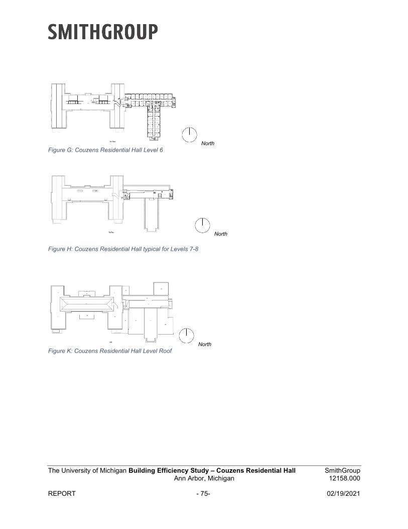
The University of Michigan Building Efficiency Study – Couzens Residential Hall SmithGroup Ann Arbor, Michigan 12158.000
REPORT - 75- 02/19/2021
NorthFigure G: Couzens Residential Hall Level 6
North
Figure H: Couzens Residential Hall typical for Levels 7-8
NorthFigure K: Couzens Residential Hall Level Roof
The University of Michigan Building Efficiency Study – Couzens Residential Hall SmithGroup Ann Arbor, Michigan 12158.000
REPORT - 76- 02/19/2021
Project Goals
Goal 1: Provide high-level energy and carbon assessment for Couzens Residential Hall
Goal 2: This study was commissioned by the President’s Commission on Carbon Neutrality (PCCN) to evaluate the existing building and identify ECM strategies to reduce energy demand and associated carbon emissions as low as possible.
Goal 3: Build upon the previous assessment framework that can be applied for other buildings/campus regions.
Data Collection and Benchmarking
Historic Climate Analysis for Ann Arbor – See Exhibit 1. Shoebox model outputs reflect historic climate data
Future Climate Analysis for Ann Arbor – See Exhibit 2. Benchmarking – See Exhibit 3. UM Office of Campus Sustainability Energy Database Analysis – See Exhibit 4.
A benchmarking study comparing the energy use intensity (EUI) of buildings of similar program on the University of Michigan Ann Arbor campus reveals that Couzens Residential Hall stands better than most of its peers in terms of energy consumption (See Exhibit 3). As measured by the Commercial Buildings Energy Consumption Survey (CBECS), Couzens Residential Hall consumes approximately 10% more energy than the average college/university building in the United States.

The University of Michigan Building Efficiency Study – Couzens Residential Hall SmithGroup Ann Arbor, Michigan 12158.000
REPORT - 77- 02/19/2021
Existing Conditions & Parallel Study
Existing Conditions
The following assumptions were made as the existing conditions for the UM Couzens Building energy model inputs:
Design Category Description of Existing Systems Source Envelope Air Tightness: Leaky/Loose (0.80 cfm/sf
of envelope)
Curtain wall: U-Factor 0.37, SHGC 0.38
Punched Window Openings: U-Factor 0.42, SHGC 0.38
Punched Stair Windows: U-Factor 1.25
Flat Roof: R-Value 15
Typical Brick Wall: R-Value 11.33
Penthouse Wall on Addition: R-Value 14.49
Stair Tower Brick Walls: R-Value 4.13
System description derived from existing drawings
Mechanical Engineering Ventilation Dorms/Apartments: DOAS FCUs with exhaust air energy recovery
Ventilation Common Areas/Offices: VAV with reheat
Cooling: One (1) 325-ton cooling tower at 38.2 gpm/ton; One (1) 325-ton screw chiller (5.5 COP)
Heating: Two (2) 2,000-MBH steam boilers at 80% efficiency
System description derived from field observation and historic drawing sets
Performance of mechanical system derived from code compliance at year of installation
Steam, chilled water, hot water systems provided from central plant and relate to ECM’s labeled “Existing”.
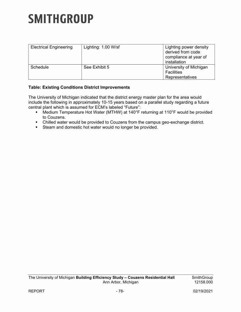
The University of Michigan Building Efficiency Study – Couzens Residential Hall SmithGroup Ann Arbor, Michigan 12158.000
REPORT - 78- 02/19/2021
Electrical Engineering Lighting: 1.00 W/sf Lighting power density derived from code compliance at year of installation
Schedule See Exhibit 5 University of Michigan Facilities Representatives
Table: Existing Conditions District Improvements
The University of Michigan indicated that the district energy master plan for the area would include the following in approximately 10-15 years based on a parallel study regarding a future central plant which is assumed for ECM’s labeled “Future”:
Medium Temperature Hot Water (MTHW) at 140°F returning at 110°F would be providedto Couzens.
Chilled water would be provided to Couzens from the campus geo-exchange district. Steam and domestic hot water would no longer be provided.
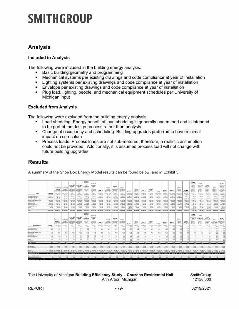
The University of Michigan Building Efficiency Study – Couzens Residential Hall SmithGroup Ann Arbor, Michigan 12158.000
REPORT - 79- 02/19/2021
Analysis
Included in Analysis
The following were included in the building energy analysis: Basic building geometry and programming Mechanical systems per existing drawings and code compliance at year of installation Lighting systems per existing drawings and code compliance at year of installation Envelope per existing drawings and code compliance at year of installation Plug load, lighting, people, and mechanical equipment schedules per University of
Michigan input
Excluded from Analysis
The following were excluded from the building energy analysis: Load shedding: Energy benefit of load shedding is generally understood and is intended
to be part of the design process rather than analysis Change of occupancy and scheduling: Building upgrades preferred to have minimal
impact on curriculum Process loads: Process loads are not sub-metered; therefore, a realistic assumption
could not be provided. Additionally, it is assumed process load will not change withfuture building upgrades.
Results
A summary of the Shoe Box Energy Model results can be found below, and in Exhibit 5:
kBtu Existing
HVAC-1A-1 Existing
Centralized Water Source
Heat Pump
HVAC-1A-2 Future
Centralized Water Source
Heat Pump
HVAC-1B-1 Existing
De-Centralized
Water Source VRF Fan
Coils
HVAC-1B-2 Future
De-Centralized
Water Source VRF Fan
Coils
HVAC-1C Existing/
FutureDe-
Centralized Air Source VRF Fan
Coils (supplement
heat)
HVAC-1D Existing/
Future De-
Centralized Air Source VRF Fan
Coils
HVAC-2OA Preheat Using CHW
HVAC-3 Preheat
Domestic Hot Water with
Sanitary Flow
HVAC-4 De-
Centralized Ground
Source Heat Pumps
HVAC-6Residential Rm Space Temp Set-
Back ELEC-1
Photovoltaics
ELEC-2Lighting
Efficiency Upgrade
ELEC-3Plugs and occupants
ARCH-1High
Performance Windows
ARCH-2Solar Shading
ARCH-3Flat Roof Insulation
ARCH-4Reinsulate
from Interior
ARCH-5Remove interior
insulation and reskin brick
ECM-AHVAC-1A-2,
ELEC-2
ECM-BHVAC-1A-2,
HVAC-2, HVAC-3, HVAC-6, ELEC-1, ELEC-2, ELEC-3, ARCH-5
ECM-CHVAC-1A-2,
HVAC-2, HVAC-3, HVAC-6, ELEC-2, ELEC-3, ARCH-5
ECM-DHVAC-1A-2,
HVAC-2, HVAC-3, HVAC-6, ELEC-1, ARCH-2
ECM-EHVAC-1A-2,
HVAC-2, HVAC-3, HVAC-6
ECM-FHVAC-1B-1,
HVAC-2, HVAC-3, HVAC-6,
ELEC-1/2/3, ARCH-
1/2/3/4/5
Interior Lighting 1,756,731 1,756,731 1,756,731 1,756,731 1,756,731 1,756,731 1,756,731 1,756,731 1,756,731 1,756,731 1,756,731 1,756,731 1,228,242 1,756,731 1,756,731 1,756,731 1,756,731 1,756,731 1,756,731 1,228,242 1,228,242 1,228,242 1,756,731 1,756,731 1,228,242 Receptacle Equipment 439,177 439,177 439,177 439,177 439,177 439,177 439,177 439,177 439,177 439,177 439,177 439,177 439,177 69,560 439,177 439,177 439,177 439,177 439,177 439,177 69,560 69,560 439,177 439,177 69,560 Space Heating - NG 8,452,750 48,102 - - - 40 - 8,087,516 8,452,750 3,717,572 8,063,383 8,452,750 8,834,398 8,684,568 7,885,698 8,507,077 8,140,427 6,733,756 5,196,579 - - - - - - Space Heating - Electricity - 2,207,151 2,222,569 1,145,737 1,144,671 2,428,463 2,431,117 - - 1,064,167 - - - - - - - - - 2,326,152 377,284 377,284 1,005,252 1,005,252 377,287 Service Water Heating - NG 3,670,238 3,670,238 3,670,238 3,670,238 3,670,238 3,670,238 3,670,238 3,670,238 2,936,179 3,670,238 3,670,238 3,670,238 3,670,238 3,670,238 3,670,238 3,670,238 3,670,238 3,670,238 3,670,238 3,670,238 2,936,179 2,936,179 2,936,179 2,936,179 2,936,179 Space Cooling 397,049 397,140 397,119 361,300 283,083 288,473 290,675 397,099 397,049 381,130 398,621 397,049 366,086 364,689 350,310 389,185 390,278 377,300 364,513 366,044 117,644 117,644 395,400 403,062 161,150
Heat Rejection 204,467 204,473 204,465 121,349 72,038 80,362 80,651 204,466 204,467 113,404 202,818 204,467 188,637 191,792 185,636 202,771 200,750 192,248 181,919 188,604 46,110 46,110 191,710 196,524 76,280 Interior Central Fans 1,348,788 1,348,788 1,348,789 1,281,445 1,281,445 1,281,445 1,281,444 1,348,788 1,348,788 1,348,874 1,349,857 1,348,788 1,351,095 1,348,745 1,331,345 1,348,570 1,341,540 1,308,929 1,275,707 1,351,086 1,281,444 1,281,444 1,370,510 1,370,890 1,281,444 Interior Local Fans 249,525 249,555 249,544 348,874 348,912 348,173 348,541 249,485 249,525 230,459 373,147 249,525 259,747 251,361 227,933 249,120 239,525 188,702 131,885 259,799 162,659 162,659 253,309 254,663 162,789 Pumps 54,537 80,862 80,868 31,104 32,685 24,235 24,218 53,450 54,537 39,581 54,990 54,537 52,426 53,059 50,858 54,116 53,699 51,467 49,555 78,929 21,368 21,368 72,090 72,035 25,110 Renewables - - - - - - - - - - - 773,384 - - - - - - - - 773,384 - 773,384 - 773,384
Total 16,573,262 10,402,217 10,369,500 9,155,955 9,028,980 10,317,337 10,322,792 16,206,950 15,839,203 12,761,333 16,308,962 15,799,878 16,390,046 16,390,743 15,897,926 16,616,985 16,232,365 14,718,548 13,066,304 9,908,271 5,467,106 6,240,490 7,646,974 8,434,513 5,544,657
EUI (kBtu/sf/yr) Existing
HVAC-1A-1 Existing
Centralized Water Source
Heat Pump
HVAC-1A-2 Future
Centralized Water Source
Heat Pump
HVAC-1B-1 Existing
De-Centralized
Water Source VRF Fan
Coils
HVAC-1B-2 Future
De-Centralized
Water Source VRF Fan
Coils
HVAC-1C Existing/
FutureDe-
Centralized Air Source VRF Fan
Coils (supplement
heat)
HVAC-1D Existing/
Future De-
Centralized Air Source VRF Fan
Coils
HVAC-2OA Preheat Using CHW
HVAC-3 Preheat
Domestic Hot Water with
Sanitary Flow
HVAC-4 De-
Centralized Ground
Source Heat Pumps
HVAC-6Residential Rm Space Temp Set-
Back ELEC-1
Photovoltaics
ELEC-2Lighting
Efficiency Upgrade
ELEC-3Plugs and occupants
ARCH-1High
Performance Windows
ARCH-2Solar Shading
ARCH-3Flat Roof Insulation
ARCH-4Reinsulate
from Interior
ARCH-5Remove interior
insulation and reskin brick
ECM-AHVAC-1a
future, ELEC-2
ECM-BHVAC-1A
future, HVAC-2, HVAC-3, HVAC-6, ELEC-1, ELEC-2, ELEC-3, ARCH-5
ECM-CHVAC-1A
future, HVAC-2, HVAC-3, HVAC-6, ELEC-2, ELEC-3, ARCH-5
ECM-DHVAC-1A
future, HVAC-2, HVAC-3, HVAC-6, ELEC-1, ARCH-2
ECM-EHVAC-1A
future, HVAC-2, HVAC-3,
HVAC-6
ECM-FHVAC-1B
existing/2/3/6, ELEC-1/2/3,
ARCH-1/2/3/4/5
Interior Lighting 10.4 10.4 10.4 10.4 10.4 10.4 10.4 10.4 10.4 10.4 10.4 10.4 7.3 10.4 10.4 10.4 10.4 10.4 10.4 7.3 7.3 7.3 10.4 10.4 7.3 Receptacle Equipment 2.6 2.6 2.6 2.6 2.6 2.6 2.6 2.6 2.6 2.6 2.6 2.6 2.6 0.4 2.6 2.6 2.6 2.6 2.6 2.6 0.4 0.4 2.6 2.6 0.4 Space Heating - NG 50.2 0.3 - - - 0.0 - 48.0 50.2 22.1 47.9 50.2 52.4 51.6 46.8 50.5 48.3 40.0 30.9 - - - - - - Space Heating - Electricity - 13.1 13.2 6.8 6.8 14.4 14.4 - - 6.3 - - - - - - - - - 13.8 2.2 2.2 6.0 6.0 2.2 Service Water Heating - NG 21.8 21.8 21.8 21.8 21.8 21.8 21.8 21.8 17.4 21.8 21.8 21.8 21.8 21.8 21.8 21.8 21.8 21.8 21.8 21.8 17.4 17.4 17.4 17.4 17.4 Space Cooling 2.4 2.4 2.4 2.1 1.7 1.7 1.7 2.4 2.4 2.3 2.4 2.4 2.2 2.2 2.1 2.3 2.3 2.2 2.2 2.2 0.7 0.7 2.3 2.4 1.0 Heat Rejection 1.2 1.2 1.2 0.7 0.4 0.5 0.5 1.2 1.2 0.7 1.2 1.2 1.1 1.1 1.1 1.2 1.2 1.1 1.1 1.1 0.3 0.3 1.1 1.2 0.5 Interior Central Fans 8.0 8.0 8.0 7.6 7.6 7.6 7.6 8.0 8.0 8.0 8.0 8.0 8.0 8.0 7.9 8.0 8.0 7.8 7.6 8.0 7.6 7.6 8.1 8.1 7.6 Interior Local Fans 1.5 1.5 1.5 2.1 2.1 2.1 2.1 1.5 1.5 1.4 2.2 1.5 1.5 1.5 1.4 1.5 1.4 1.1 0.8 1.5 1.0 1.0 1.5 1.5 1.0 Pumps 0.3 0.5 0.5 0.2 0.2 0.1 0.1 0.3 0.3 0.2 0.3 0.3 0.3 0.3 0.3 0.3 0.3 0.3 0.3 0.5 0.1 0.1 0.4 0.4 0.1 Renewables - - - - - - - - - - - 4.6 - - - - - - - - 4.6 - 4.6 - 4.6
Total (kBtu/sf/yr) 98.4 61.8 61.6 54.4 53.6 61.3 61.3 96.2 94.0 75.8 96.8 93.8 97.3 97.3 94.4 98.6 96.4 87.4 77.6 58.8 32.5 37.0 45.4 50.1 32.9 Savings 37% 37% 45% 46% 38% 38% 2% 4% 23% 2% 5% 1% 1% 4% 0% 2% 11% 21% 40% 67% 62% 54% 49% 67%
Elec (Mmbtu) 4,450 6,684 6,699 5,486 5,359 6,647 6,653 4,449 4,450 5,374 4,575 3,677 3,885 4,036 4,342 4,440 4,422 4,315 4,199 6,238 2,531 3,304 4,711 5,498 2,608 Nat Gas (Mmbtu) 12,123 3,718 3,670 3,670 3,670 3,670 3,670 11,758 11,389 7,388 11,734 12,123 12,505 12,355 11,556 12,177 11,811 10,404 8,867 3,670 2,936 2,936 2,936 2,936 2,936
Elec ($) 112,170$ 168,468$ 168,856$ 138,268$ 135,068$ 167,540$ 167,679$ 112,143$ 112,170$ 135,440$ 115,322$ 92,677$ 97,932$ 101,726$ 109,441$ 111,903$ 111,450$ 108,749$ 105,849$ 157,231$ 63,792$ 83,286$ 118,736$ 138,586$ 65,747$ Nat Gas ($) 39,786$ 12,203$ 12,045$ 12,045$ 12,045$ 12,045$ 12,045$ 38,587$ 37,377$ 24,246$ 38,508$ 39,786$ 41,038$ 40,547$ 37,925$ 39,964$ 38,761$ 34,144$ 29,100$ 12,045$ 9,636$ 9,636$ 9,636$ 9,636$ 9,636$
Total Energy Cost ($) 151,956$ 180,671$ 180,901$ 150,314$ 147,113$ 179,585$ 179,724$ 150,730$ 149,547$ 159,686$ 153,830$ 132,462$ 138,971$ 142,273$ 147,365$ 151,867$ 150,211$ 142,893$ 134,948$ 169,276$ 73,429$ 92,922$ 128,372$ 148,222$ 75,383$
Elec (metric tons CO2) 777 1,166 1,169 957 935 1,160 1,161 776 777 938 798 642 678 704 758 775 772 753 733 1,089 442 577 822 959 455 Nat Gas (metric tons CO2) 643 197 195 195 195 195 195 624 604 392 623 643 664 656 613 646 627 552 471 195 156 156 156 156 156
Total Carbon (metric tons CO2) 1,420 1,364 1,364 1,152 1,130 1,355 1,356 1,400 1,381 1,330 1,421 1,285 1,342 1,360 1,371 1,421 1,398 1,305 1,203 1,283 597 732 978 1,115 611
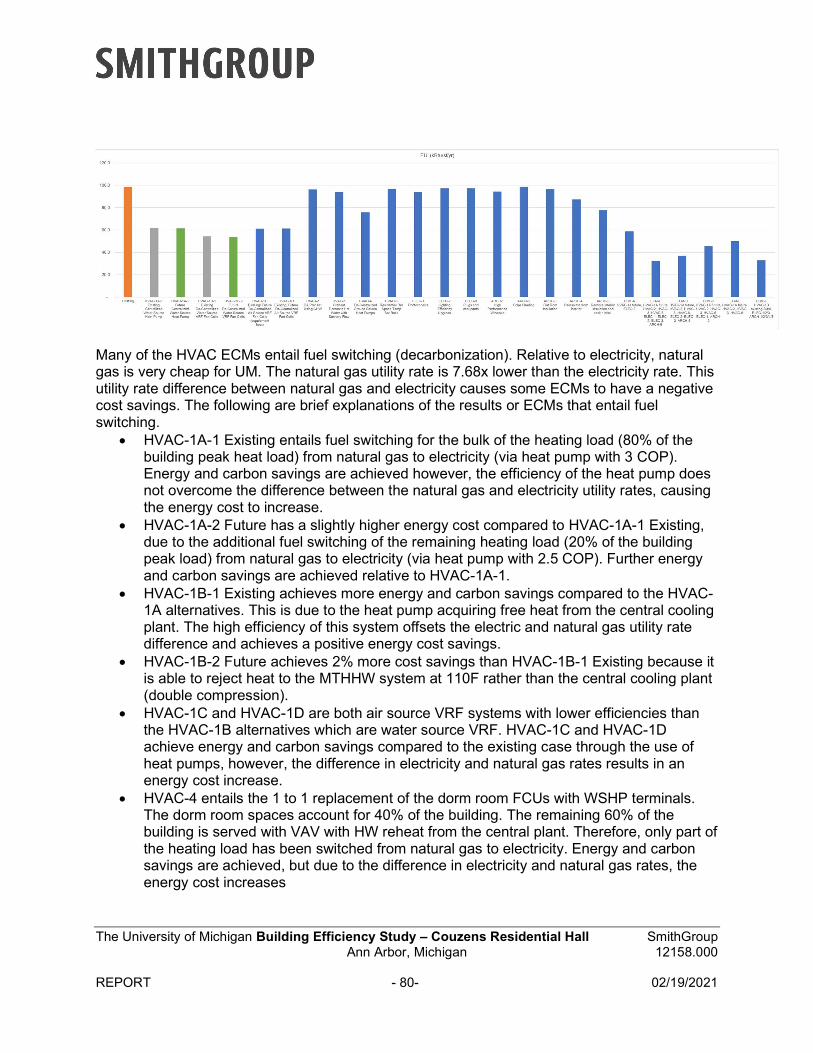
The University of Michigan Building Efficiency Study – Couzens Residential Hall SmithGroup Ann Arbor, Michigan 12158.000
REPORT - 80- 02/19/2021
Many of the HVAC ECMs entail fuel switching (decarbonization). Relative to electricity, natural gas is very cheap for UM. The natural gas utility rate is 7.68x lower than the electricity rate. This utility rate difference between natural gas and electricity causes some ECMs to have a negative cost savings. The following are brief explanations of the results or ECMs that entail fuel switching.
HVAC-1A-1 Existing entails fuel switching for the bulk of the heating load (80% of thebuilding peak heat load) from natural gas to electricity (via heat pump with 3 COP).Energy and carbon savings are achieved however, the efficiency of the heat pump doesnot overcome the difference between the natural gas and electricity utility rates, causingthe energy cost to increase.
HVAC-1A-2 Future has a slightly higher energy cost compared to HVAC-1A-1 Existing,due to the additional fuel switching of the remaining heating load (20% of the buildingpeak load) from natural gas to electricity (via heat pump with 2.5 COP). Further energyand carbon savings are achieved relative to HVAC-1A-1.
HVAC-1B-1 Existing achieves more energy and carbon savings compared to the HVAC-1A alternatives. This is due to the heat pump acquiring free heat from the central coolingplant. The high efficiency of this system offsets the electric and natural gas utility ratedifference and achieves a positive energy cost savings.
HVAC-1B-2 Future achieves 2% more cost savings than HVAC-1B-1 Existing because itis able to reject heat to the MTHHW system at 110F rather than the central cooling plant(double compression).
HVAC-1C and HVAC-1D are both air source VRF systems with lower efficiencies thanthe HVAC-1B alternatives which are water source VRF. HVAC-1C and HVAC-1Dachieve energy and carbon savings compared to the existing case through the use ofheat pumps, however, the difference in electricity and natural gas rates results in anenergy cost increase.
HVAC-4 entails the 1 to 1 replacement of the dorm room FCUs with WSHP terminals.The dorm room spaces account for 40% of the building. The remaining 60% of thebuilding is served with VAV with HW reheat from the central plant. Therefore, only part ofthe heating load has been switched from natural gas to electricity. Energy and carbonsavings are achieved, but due to the difference in electricity and natural gas rates, theenergy cost increases
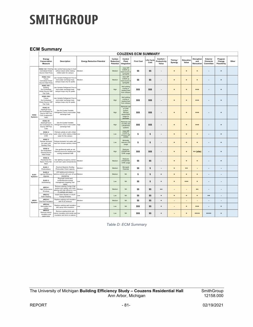
The University of Michigan Building Efficiency Study – Couzens Residential Hall SmithGroup Ann Arbor, Michigan 12158.000
REPORT - 81- 02/19/2021
ECM Summary
Table D: ECM Summary
Energy Conservation
Measure Description Energy Reduction Potential
Carbon Reduction Potential
Central Plant
IntegrationFirst Cost
Life Cycle Cost
Comfort / Productivity
Value
Timing / Synergy
Education Value
Disruption and
Relocation
Exterior Elements
Committee
Program Change
PossibilityOther
HVAC-1A-1 ExistingCentralized Water Source Heat Pump
Use central heat pumps to heat without steam while making
chilled water for campusMedium Medium
Uses 58F CHWR as
heat source in spring/fall
$$ $$ - + + + - +
HVAC-1A-2 Future
Centralized Water Source Heat Pump
Use Variable Refrigerant Flow to recirculate/ exchange heat,
campus loops only for peaksMedium Medium
Uses 58F CHWR as
heat source in spring/fall
$$ $$ - + + + - +
HVAC-1B-1 Existing
De-Centralized Water Source VRF
Fan Coils
Use Variable Refrigerant Flow to recirculate/ exchange heat,
campus loops only for peaksHigh High
Net building cooling or
heating load from campus
$$$ $$$ - + + +++ - +
HVAC-1B-2 Future
De-Centralized Water Source VRF
Fan Coils
Use Variable Refrigerant Flow to recirculate/ exchange heat,
campus loops only for peaksHigh High
Net building cooling or
heating load from campus
$$$ $$$ - + + +++ - +
HVAC-1C Existing/Future
De-Centralized Air Source VRF Fan
Coils (supplement heat)
Use Air-Cooled Variable Refrigerant Flow to recirculate/
exchange heatHigh High
Removes use of CHW system. Minimal
steam/HHW usage for perimeter
$$$ $$$ - + + +++ - +
HVAC-1D Existing/Future
De-Centralized Air Source VRF Fan
Coils
Use Air-Cooled Variable Refrigerant Flow to recirculate/
exchange heatHigh High
Removes use of CHW and LPS/MTHW
systems
$$$ $$$ - + + +++ - +
HVAC-2OA Preheat using
CHW
Preheat outside air with chilled water return while making chilled
water for the campusLow Low
Uses 62F CHWR to
produce 42F CHWS
$ $ - + + + - +
HVAC-3Preheat domestic
hot water with Sanitary Flow
Preheat domestic hot water with heat from shower sanitary drains
Low LowMinimally
reduces LPS usage
$ $ - + + + - +
HVAC-4De-Centralized Ground Source
Heat Pumps
Use geothermal wells as net thermal source for heating and
cooling residential hallsHigh High
Reduces LPS/MTHW, CHW usage
$$$ $$$ - + + ++ (site) - +
HVAC-6Residential Rm
Space Temp Set-Back
Use lighting occupancy sensor to set back space temperatures
Medium MediumReduces
LPS/MTHW, CHW usage
$$ $$ - + + + - +
ELEC-1Photovoltaics
Practical Maximim Rooftop Photovoltaic Panel capacity
Medium MediumMicrogrid Potential $$ $ - + ++ - - -
ELEC-2Lighting Efficiency
Upgrade
LED lighting and enhance lighting controls with auto off and
daylightingMedium Medium NA $ $ + + + + - -
ELEC-3Submetering
Plug load control and comprehensive energy
management targeting user habits
Low Low NA $$ $ + + +++ + - -
ARCH-1High Performance
Windows
Remove existing Curtain Wall system and replace with triple
glazing with high efficiency Low-E coatings and argon
Medium Medium NA $$ $$ ++ - - ++ - -
ARCH-2Solar Shading
Install Solar Shades on South Facing Windows
Low Low NA $$ $$ + + + + ++ -
ARCH-3Flat Roof Insulation
Replace existing roof insulation with R-30 minimum
Medium Medium NA $$ $$ + - - - - -
ARCH-4Reinsulate from
Interior
Replace existing wall insulation with spray foam insulation
Low Low NA $$$ $$ + - + +++ - +
ARCH-5Remove interior insulation and reskin brick
Remove existing brick and interior insulation and install new insulation and brick on exterior
Low Low NA $$$ $$ + - + ++++ ++++ +
COUZENS ECM SUMMARY
HVAC Systems
ELEC Systems
ARCH Systems
The University of Michigan Building Efficiency Study – Couzens Residential Hall SmithGroup Ann Arbor, Michigan 12158.000
REPORT - 82- 02/19/2021
Life Cycle Cost
The Life Cycle Cost (LCC) Analysis is a very high-level study intended for comparison purposes. It is a method for assessing the total cost of ownership in present value terms which considers all costs of acquiring, owning, and disposing of a building or building system. Important information regarding cost model content and assumptions is listed below:
1.35 Factor utilized for soft costs to convert estimated construction costs into projectcosts; construction contingency is part of 1.35 factor
Estimates include 5% for construction escalation per year for two years Suggested 2.5% inflation rate (UM) for the duration of the payback period replaced with
US Department of Energy Escalation Projections (Exhibit 7) Estimates assume UM Cost of Money at 3%, this is the estimated average cost of
borrowing. Current campus utility rates.
Natural Gas Rate: $3.40/Mcf Electricity Rate: $0.086/kWh
30 Year lifespan of all equipment, with a project start date of 2023 Estimates exclude maintenance costs associated with systems upgrades Estimates assume General Contractor format for construction Estimates assume no relocation Estimate assumes building is fully vacated throughout renovation Estimate should be understood as high-level and for comparative purposes; not for
project use
ECM-A: Project Cost = $10,152,000 Total Life Cycle Cost = $13,517,722 (Refer to Exhibit 8 for detailed analysis) Risk: The potential risk factors include the accuracy of the opinion of costs due to high
level concept designs rather than detailed designs and existing condition observations,rather than detailed investigation or confirmation of quantities. These risks are mitigatedby contingencies in the initial cost opinion. The system concepts are known provensystems that mitigates the risks associated with the energy and performanceevaluations.
ECM-B: Project Cost = $63,082,800 Total Life Cycle Cost = $66,863,258 (Refer to Exhibit 8 for detailed analysis) PV Maintenance: The local climate experiences enough precipitation to self-clean the
PV modules and periodic cleaning/washing is not required. An annual inspection of thesystem is recommended. The annual inspection includes visually inspecting modules,inverters, wiring and other balance of system (BOS) components. Replacing deficientcomponents, tightening wiring connections and removing debris in and around the arrayare some of the tasks that may be required to maintain the system. Overall,maintenance costs for an annual inspection should be approximately $4,000.
The University of Michigan Building Efficiency Study – Couzens Residential Hall SmithGroup Ann Arbor, Michigan 12158.000
REPORT - 83- 02/19/2021
Risk: The potential risk factors include the accuracy of the opinion of costs due to highlevel concept designs rather than detailed designs and existing condition observations,rather than detailed investigation or confirmation of quantities. These risks are mitigatedby contingencies in the initial cost opinion. The new enclosure system with this optionincludes more risk associated with unforeseen existing conditions regarding the integrityof the existing structural system that could support the new enclosure.
ECM-C: Project Cost = $60,825,600 Total Life Cycle Cost = $64,852,582 (Refer to Exhibit 8 for detailed analysis) The potential risk factors include the accuracy of the opinion of costs due to high level
concept designs rather than detailed designs and existing condition observations, ratherthan detailed investigation or confirmation of quantities. These risks are mitigated bycontingencies in the initial cost opinion. The new enclosure system with this optionincludes more risk associated with unforeseen existing conditions regarding the integrityof the existing structural system that could support the new enclosure.
ECM-D: Project Cost = $9,213,750 Total Life Cycle Cost = $11,828,049 (Refer to Exhibit 8 for detailed analysis) The potential risk factors include the accuracy of the opinion of costs due to high level
concept designs rather than detailed designs and existing condition observations, ratherthan detailed investigation or confirmation of quantities. These risks are mitigated bycontingencies in the initial cost opinion.
ECM-E: Project Cost = $4,684,500 Total Life Cycle Cost = $7,462,359 (Refer to Exhibit 8 for detailed analysis) The potential risk factors include the accuracy of the opinion of costs due to high level
concept designs rather than detailed designs and existing condition observations, ratherthan detailed investigation or confirmation of quantities. These risks are mitigated bycontingencies in the initial cost opinion.
ECM-F: Project Cost = $99,812,250 Total Life Cycle Cost = $105,065,305 (Refer to Exhibit 8 for detailed analysis) The potential risk factors include the accuracy of the opinion of costs due to high level
concept designs rather than detailed designs and existing condition observations, ratherthan detailed investigation or confirmation of quantities. These risks are mitigated bycontingencies in the initial cost opinion. The new enclosure system with this optionincludes more risk associated with unforeseen existing conditions regarding the integrityof the existing structural system that could support the new enclosure.
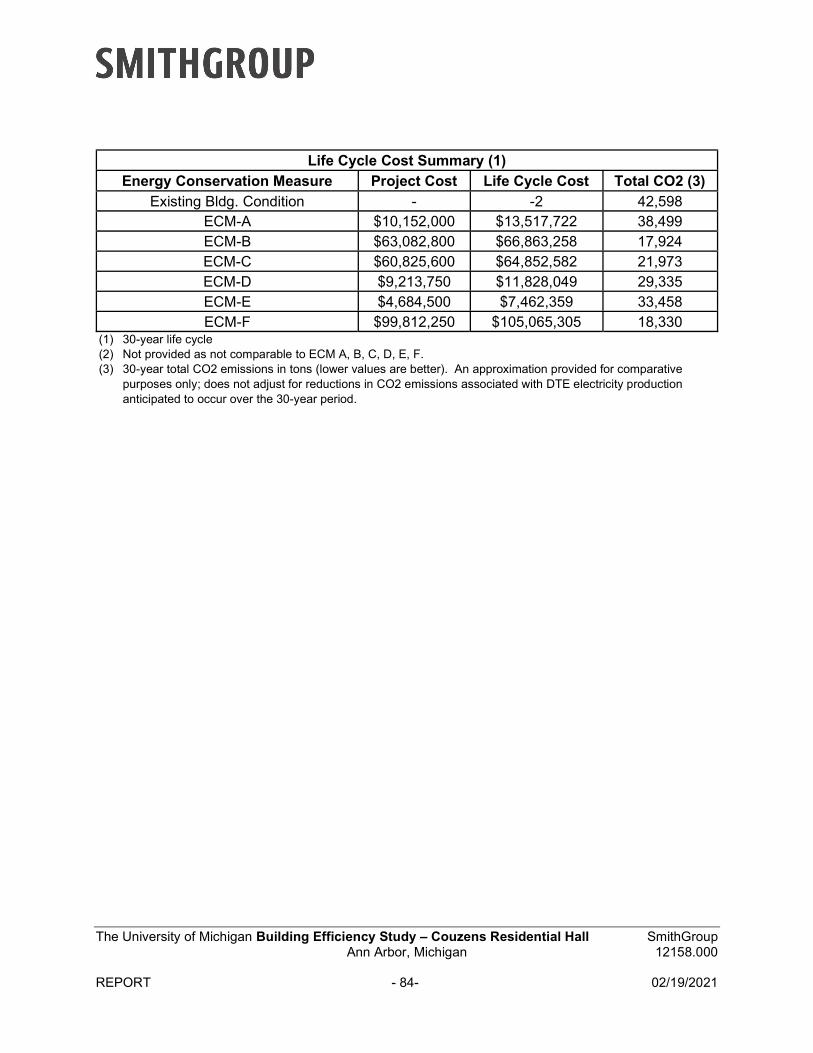
The University of Michigan Building Efficiency Study – Couzens Residential Hall SmithGroup Ann Arbor, Michigan 12158.000
REPORT - 84- 02/19/2021
Life Cycle Cost Summary (1) Energy Conservation Measure Project Cost Life Cycle Cost Total CO2 (3)
Existing Bldg. Condition - -2 42,598 ECM-A $10,152,000 $13,517,722 38,499 ECM-B $63,082,800 $66,863,258 17,924 ECM-C $60,825,600 $64,852,582 21,973 ECM-D $9,213,750 $11,828,049 29,335 ECM-E $4,684,500 $7,462,359 33,458 ECM-F $99,812,250 $105,065,305 18,330
(1) 30-year life cycle(2) Not provided as not comparable to ECM A, B, C, D, E, F.(3) 30-year total CO2 emissions in tons (lower values are better). An approximation provided for comparative
purposes only; does not adjust for reductions in CO2 emissions associated with DTE electricity productionanticipated to occur over the 30-year period.