Embed Size (px)
Citation preview
ni.com
Building Complex Systems with COTS Software Defined Radios
Sarah Yost
Product Marketing Manager, National Instruments
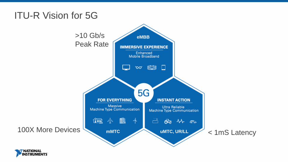
ITU-R Vision for 5G
eMBB
uMTC, UR/LLmMTC
>10 Gb/s
Peak Rate
< 1mS Latency100X More Devices
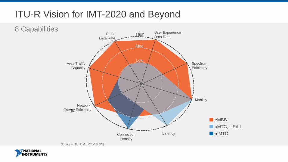
ITU-R Vision for IMT-2020 and Beyond
8 Capabilities
Connection
Density
Network
Energy Efficiency
Area Traffic
Capacity
Peak
Data Rate
Low
Med
Latency
User Experience
Data Rate
Spectrum
Efficiency
Mobility
High
Source – ITU-R M.[IMT.VISION]
eMBB
uMTC, UR/LL
mMTC

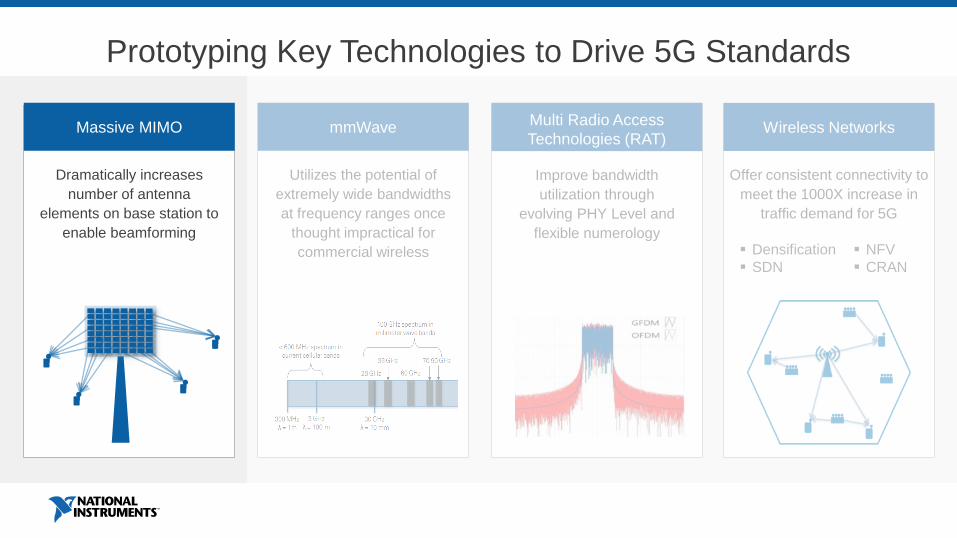
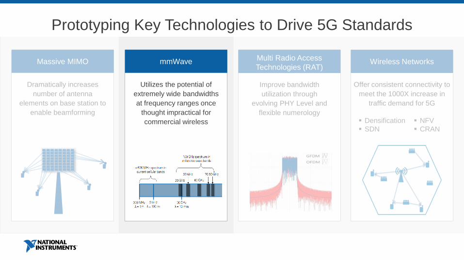
Prototyping Key Technologies to Drive 5G Standards
Improve bandwidth
utilization through
evolving PHY Level and
flexible numerology
Multi Radio Access
Technologies (RAT)
Utilizes the potential of
extremely wide bandwidths
at frequency ranges once
thought impractical for
commercial wireless
mmWave
Dramatically increases
number of antenna
elements on base station to
enable beamforming
Massive MIMO
Offer consistent connectivity to
meet the 1000X increase in
traffic demand for 5G
Wireless Networks
Densification
SDN
NFV
CRAN

5G Testbed Examples
University of
Bristol and
Lund University
128-Antenna
Massive MIMO
AT&T
28 GHz Channel
Sounder
DARPA
Spectrum
Collaboration
Challenge
Nokia
First mmWave
Prototypes
14.5 Gbps
Prototyping Key Technologies to Drive 5G Standards
Improve bandwidth
utilization through
evolving PHY Level and
flexible numerology
Multi Radio Access
Technologies (RAT)
Utilizes the potential of
extremely wide bandwidths
at frequency ranges once
thought impractical for
commercial wireless
mmWave
Dramatically increases
number of antenna
elements on base station to
enable beamforming
Massive MIMO
Offer consistent connectivity to
meet the 1000X increase in
traffic demand for 5G
Wireless Networks
Densification
SDN
NFV
CRAN

Data lines
Clock (10 MHz & PPS) lines
Start Trigger (return signal)
128 Channel System
8374
8374
8135
8374
6674T
8374
8374
8374
8374
8374
7976R
7976R
7976R
7976R
...USRPs 1-8
...USRPs 9-16
...USRPs 17-
24
...USRPs 25-32
...USRPs 33-40
...USRPs 41-48
...USRPs 49-56
...USRPs 57-64
Master Distribution
CDA-2990
Slave
CDA-2990Slave
CDA-2990
Slave
CDA-2990
Slave
CDA-2990
Slave
CDA-2990
Slave
CDA-2990
Slave
CDA-2990
Slave
CDA-2990
PCIe
SwitchboxPCIe
SwitchboxPCIe
Switchbox
PCIe
Switchbox
PCIe
Switchbox
PCIe
SwitchboxPCIe
Switchbox
PCIe
Switchbox
8 USRP RIO 8 USRP RIO 8 USRP RIO 8 USRP RIO 8 USRP RIO 8 USRP RIO 8 USRP RIO8 USRP RIO
Host
PXI Chassis
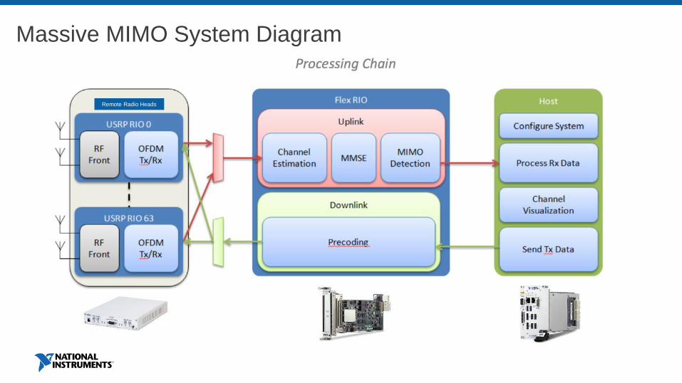
Massive MIMO System Diagram
Remote Radio Heads
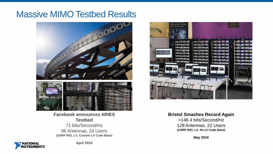
Facebook announces ARIES
Testbed
71 bits/Second/Hz
96 Antennas, 24 Users(USRP RIO, LV, Custom LV Code Base)
April 2016
Bristol Smashes Record Again
>146.4 bits/Second/Hz
128 Antennas, 22 Users(USRP RIO, LV, NI LU Code Base)
May 2016
Massive MIMO Testbed Results
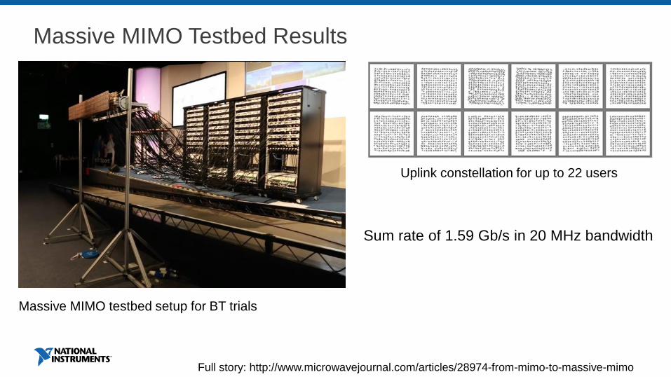
Massive MIMO Testbed Results
Full story: http://www.microwavejournal.com/articles/28974-from-mimo-to-massive-mimo
Uplink constellation for up to 22 users
Massive MIMO testbed setup for BT trials
Sum rate of 1.59 Gb/s in 20 MHz bandwidth
Prototyping Key Technologies to Drive 5G Standards
Improve bandwidth
utilization through
evolving PHY Level and
flexible numerology
Multi Radio Access
Technologies (RAT)
Utilizes the potential of
extremely wide bandwidths
at frequency ranges once
thought impractical for
commercial wireless
mmWave
Dramatically increases
number of antenna
elements on base station to
enable beamforming
Massive MIMO
Offer consistent connectivity to
meet the 1000X increase in
traffic demand for 5G
Wireless Networks
Densification
SDN
NFV
CRAN
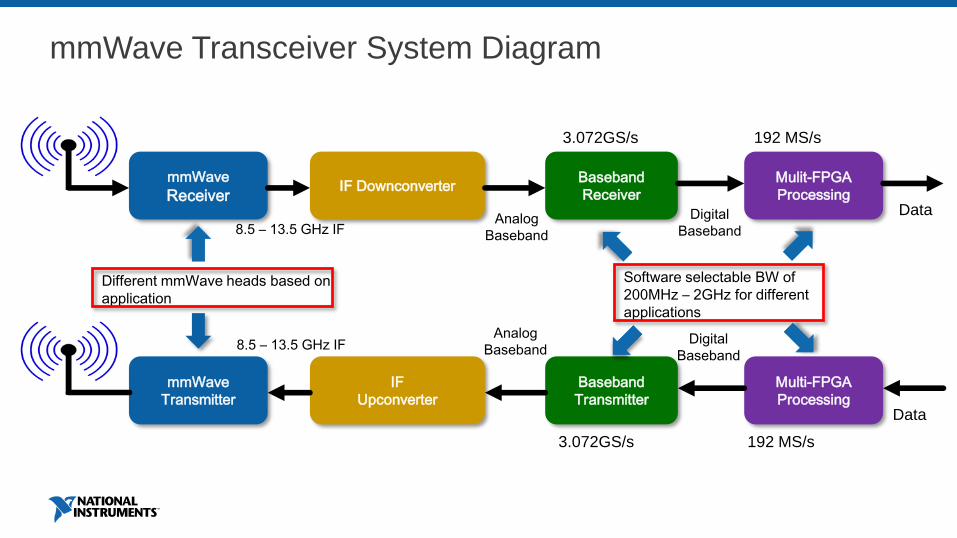
mmWave Transceiver System Diagram
mmWave
ReceiverIF Downconverter
Baseband
Receiver
Mulit-FPGA
ProcessingData
8.5 – 13.5 GHz IFAnalog
Baseband
Digital
Baseband
mmWave
Transmitter
IF
Upconverter
Baseband
Transmitter
Multi-FPGA
Processing
Analog
BasebandDigital
Baseband
Data
Software selectable BW of
200MHz – 2GHz for different
applications
Different mmWave heads based on
application
3.072GS/s
3.072GS/s
192 MS/s
192 MS/s
8.5 – 13.5 GHz IF
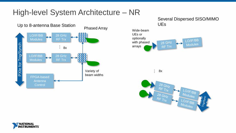
High-level System Architecture – NR
28 GHz
RF Trx
LO/IF/BB
Modules
28 GHz
RF Trx
LO/IF/BB
Modules
…
FPGA-based
Antenna
Control
8x
PX
Ie f
or
Trig/S
yn
ch
Up to 8-antenna Base Station
Several Dispersed SISO/MIMO
UEs
… 8xVariety of
beam widths
Phased ArrayWide-beam
UEs or
optionally
with phased
arrays
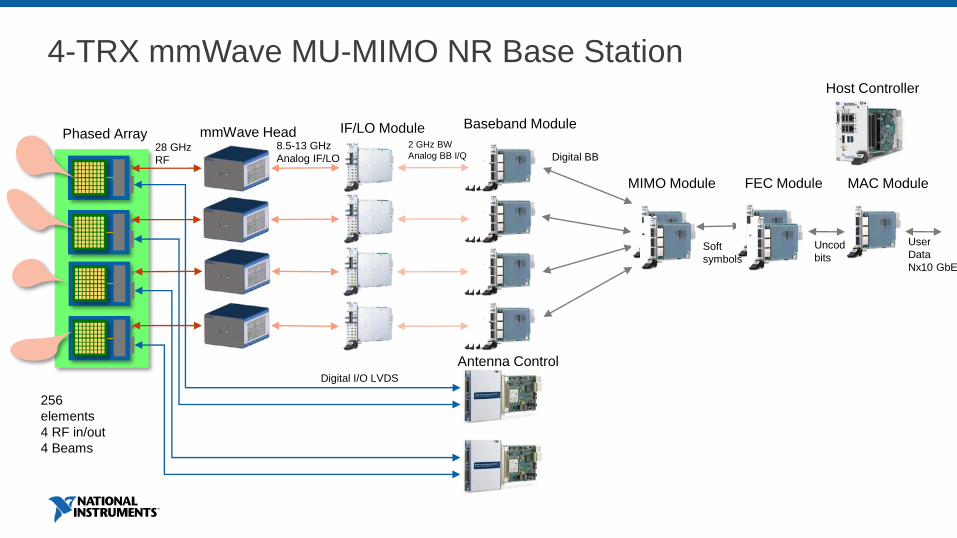
4-TRX mmWave MU-MIMO NR Base Station
Phased Array mmWave Head
Antenna ControlDigital I/O LVDS
28 GHz
RF
256
elements
4 RF in/out
4 Beams
IF/LO Module Baseband Module
8.5-13 GHz
Analog IF/LO
2 GHz BW
Analog BB I/Q Digital BB
MIMO Module
Soft
symbols
FEC Module
Uncoded
bits
Host Controller
MAC Module
User
Data
Nx10 GbE

mmWave Testbed Results
28 GHz, 8x100 MHz OFDM, 2x2 MU-MIMO w/hybrid
beamforming
2-Transceiver Base Station
2 x 64-antenna phased array
UE0:
64-QAM
2.9 Gbps
UE1:
16-QAM
1.8 Gbps
64-antenna
phased arrays
Vertical
polarization
Dynamic TDD
with self-
contained
subframe
28 GHz
mmWave
TRX Head
2x2 BB/IF
Chassis
Horizontal
polarization
28 GHz
mmWave
TRX Head
with horn
antennaUE Interface with
video streaming
Beamsteering
Interface
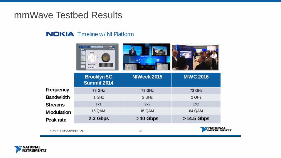
mmWave Testbed Results
39| NI CONFIDENTIAL
Timeline w/ NI Platform
Brooklyn 5G
Summit 2014
NIWeek 2015 MWC 2016
73 GHz 73 GHz 73 GHz
1 GHz 2 GHz 2 GHz
1x1 2x2 2x2
16 QAM 16 QAM 64 QAM
2.3 Gbps >10 Gbps >14.5 Gbps
Frequency
Bandwidth
Streams
Modulation
Peak rate
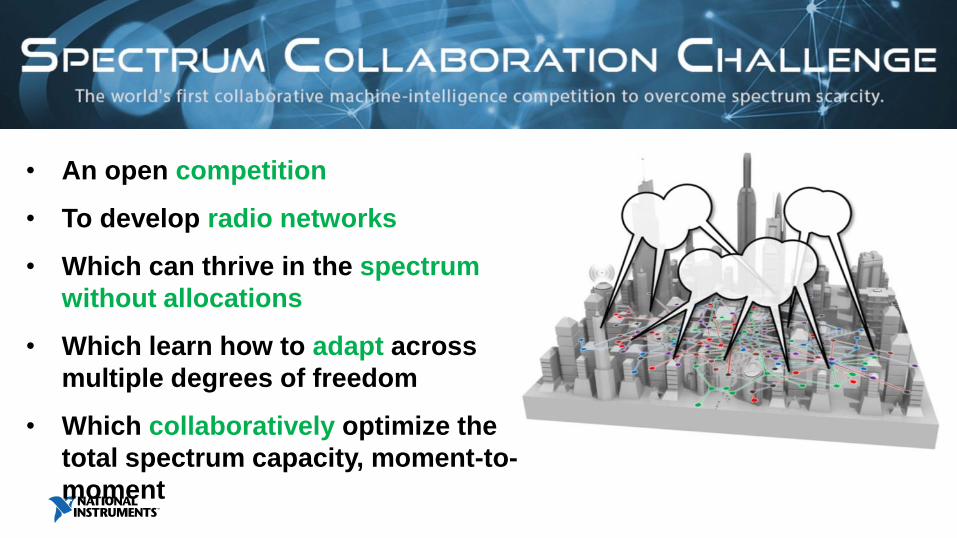
• An open competition
• To develop radio networks
• Which can thrive in the spectrum
without allocations
• Which learn how to adapt across
multiple degrees of freedom
• Which collaboratively optimize the
total spectrum capacity, moment-to-
moment
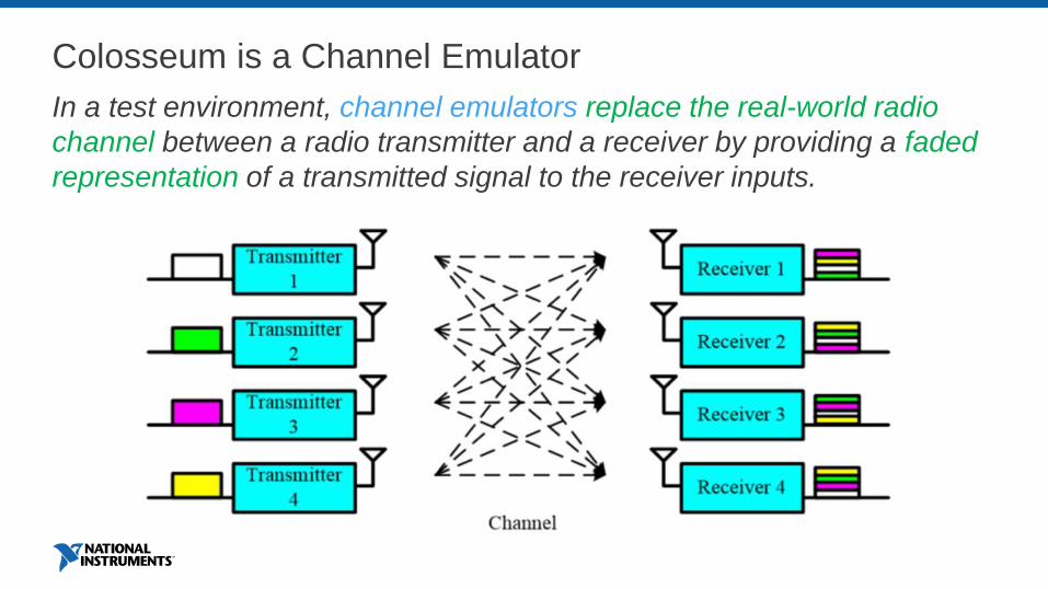
Colosseum is a Channel Emulator
In a test environment, channel emulators replace the real-world radio
channel between a radio transmitter and a receiver by providing a faded
representation of a transmitted signal to the receiver inputs.

Colosseum is a Channel Emulator
In a test environment, channel emulators replace the real-world radio
channel between a radio transmitter and a receiver by providing a faded
representation of a transmitted signal to the receiver inputs.

Colosseum Block Diagram
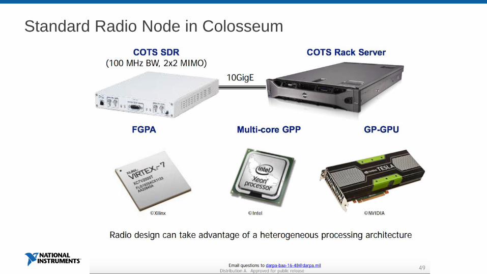
Standard Radio Node in Colosseum
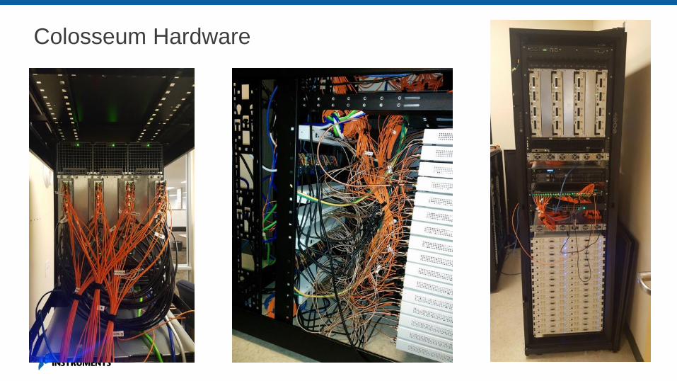
Colosseum Hardware

SC2 Update
Phase 1 hurdles to wrap up in December 2017
Phase 2 registration is open until January 2018
Want to learn more about joining?
Check out https://spectrumcollaborationchallenge.com

Questions