Embed Size (px)
Citation preview

© 2012 CAE Associates Inc. and ANSYS Inc. All rights reserved.
Building Better
Boundary Conditions eLearning
Peter Barrett
December 2012

2
Assembly Modeling Webinar
Do you effectively manage your boundary conditions?
— Do you take full advantage of symmetry and/or simplified connections?
This webinar will demonstrate:
— How to evaluate boundary conditions
— Efficiently utilize remote supports
— Apply symmetry, anti-symmetry, and cyclic BC’s
— Apply nodal-based BC’s
— Expose the features of advanced connections
3
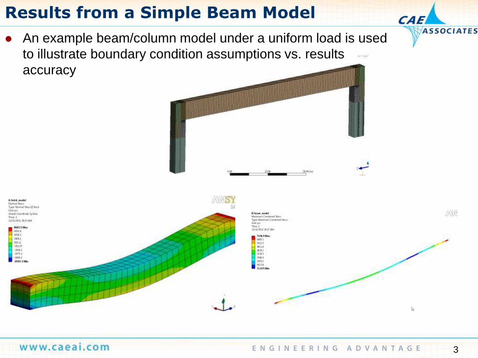
Results from a Simple Beam Model
An example beam/column model under a uniform load is used
to illustrate boundary condition assumptions vs. results
accuracy

4
Results from a Simple Beam Model Model Just the Beam
— Brick meshed beam
— Higher order brick elements
— Coarse mesh vs. fine mesh
— Varied support conditions
Beam element model
— Beam (188) modeled fixed and
pinned supports
— Coarse mesh vs. Fine mesh
Coarse Mesh
Fine Mesh (1/4 symmetry model)
5
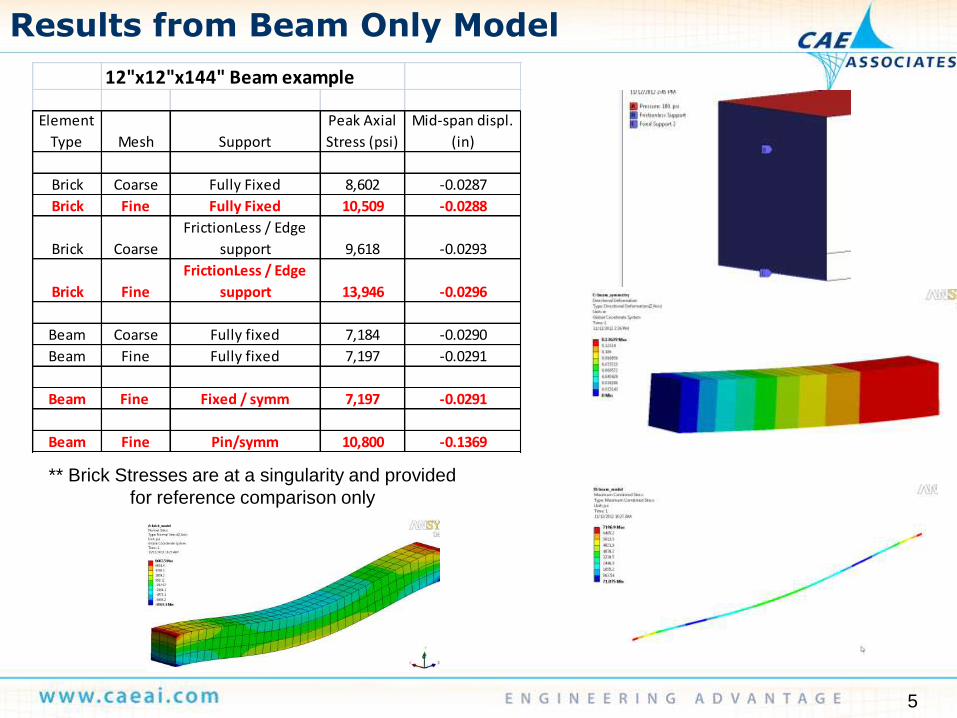
Results from Beam Only Model
12"x12"x144" Beam example
Element
Type Mesh Support
Peak Axial
Stress (psi)
Mid-span displ.
(in)
Brick Coarse Fully Fixed 8,602 -0.0287
Brick Fine Fully Fixed 10,509 -0.0288
Brick Coarse
FrictionLess / Edge
support 9,618 -0.0293
Brick Fine
FrictionLess / Edge
support 13,946 -0.0296
Beam Coarse Fully fixed 7,184 -0.0290
Beam Fine Fully fixed 7,197 -0.0291
Beam Fine Fixed / symm 7,197 -0.0291
Beam Fine Pin/symm 10,800 -0.1369
** Brick Stresses are at a singularity and provided
for reference comparison only
6
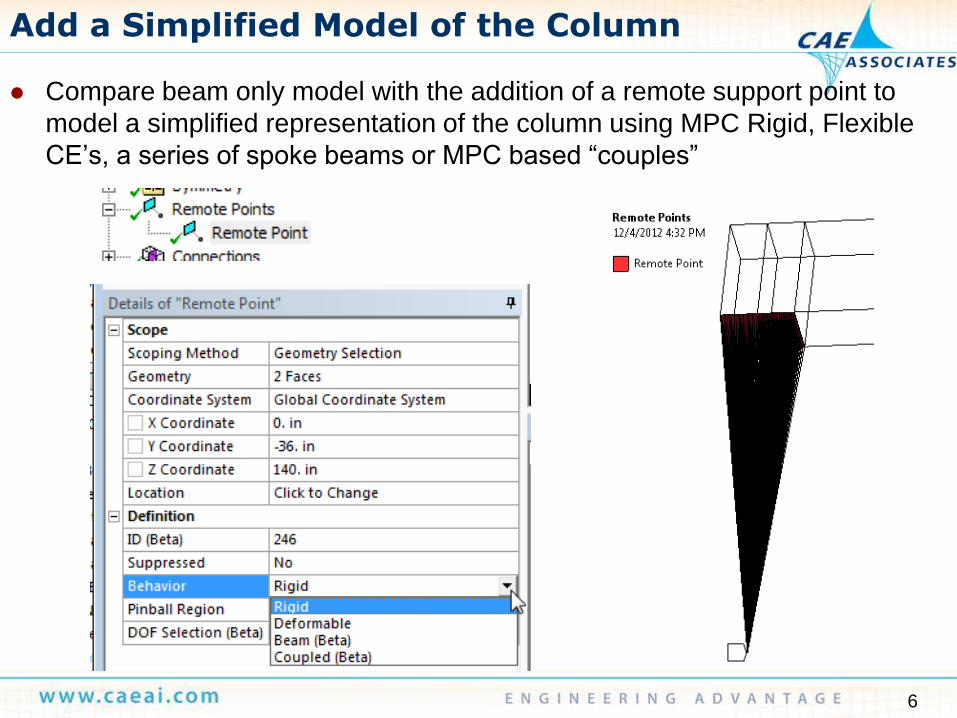
Add a Simplified Model of the Column
Compare beam only model with the addition of a remote support point to
model a simplified representation of the column using MPC Rigid, Flexible
CE’s, a series of spoke beams or MPC based “couples”
7
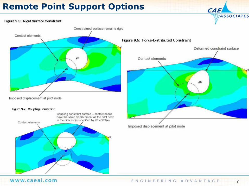
Remote Point Support Options

8
“Beta” Beam Support
Beam Method
— Creates a series of “spokes”
from remote point to surface
nodes
— Cross sectional area is
approximately equal to nodal
surface area
9
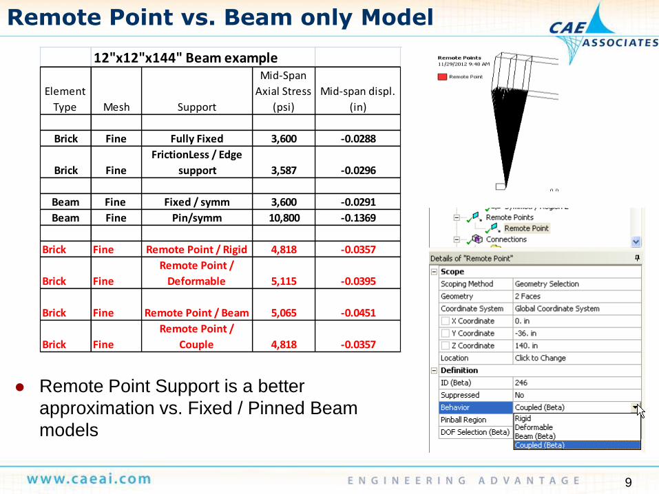
Remote Point vs. Beam only Model
Remote Point Support is a better
approximation vs. Fixed / Pinned Beam
models
12"x12"x144" Beam example
Element
Type Mesh Support
Mid-Span
Axial Stress
(psi)
Mid-span displ.
(in)
Brick Fine Fully Fixed 3,600 -0.0288
Brick Fine
FrictionLess / Edge
support 3,587 -0.0296
Beam Fine Fixed / symm 3,600 -0.0291
Beam Fine Pin/symm 10,800 -0.1369
Brick Fine Remote Point / Rigid 4,818 -0.0357
Brick Fine
Remote Point /
Deformable 5,115 -0.0395
Brick Fine Remote Point / Beam 5,065 -0.0451
Brick Fine
Remote Point /
Couple 4,818 -0.0357

10
Model the Column Explicitly
Model the Column explicitly with combined solid & beam mesh using MPC
Bonded Vertex to Face Contact to extend the column model
— Column to beam interface is modeled both bonded and frictionless

11
Beam-Column vs. Simplified Methods
For the Beam/Column Rigid connection, the
remote Point/Beam option is a reasonable
approximation
For the Frictionless Column/Beam Connection,
a pinned beam element is a reasonable
approach
12"x12"x144" Beam example
Element
Type Mesh Support
Mid-Span
Axial Stress
(psi)
Mid-span displ.
(in)
Brick Fine Fully Fixed 3,600 -0.0288
Brick Fine
FrictionLess / Edge
support 3,587 -0.0296
Beam Fine Fixed / symm 3,600 -0.0291
Beam Fine Pin/symm 10,800 -0.1369
Brick Fine Remote Point / Beam 5,065 -0.0451
Brick Coarse
Bonded Support
Modeled 6,450 -0.0780
Brick Fine
Frictionless Support
Modeled 10,108 -0.1274
13
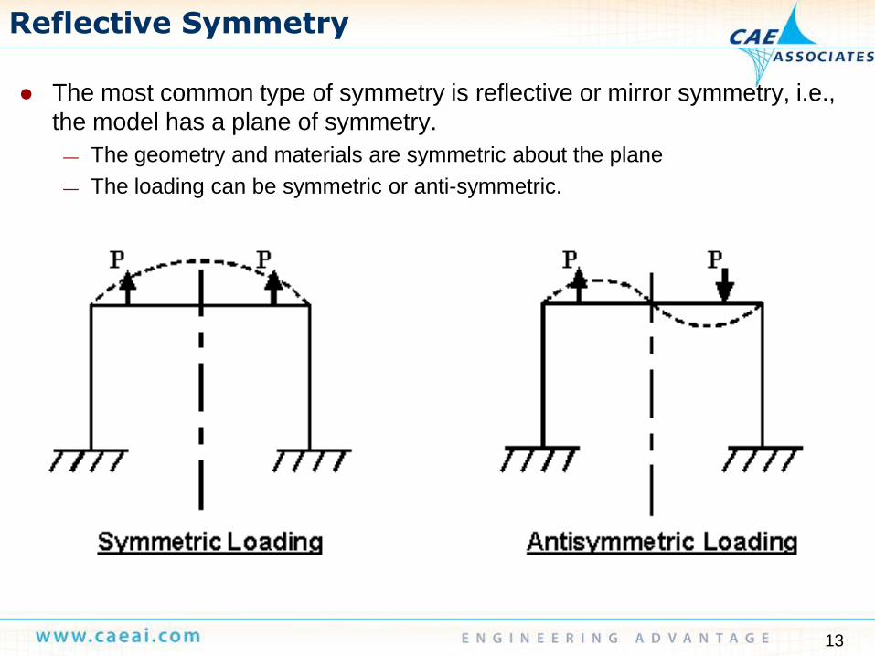
Reflective Symmetry
The most common type of symmetry is reflective or mirror symmetry, i.e.,
the model has a plane of symmetry.
— The geometry and materials are symmetric about the plane
— The loading can be symmetric or anti-symmetric.
14
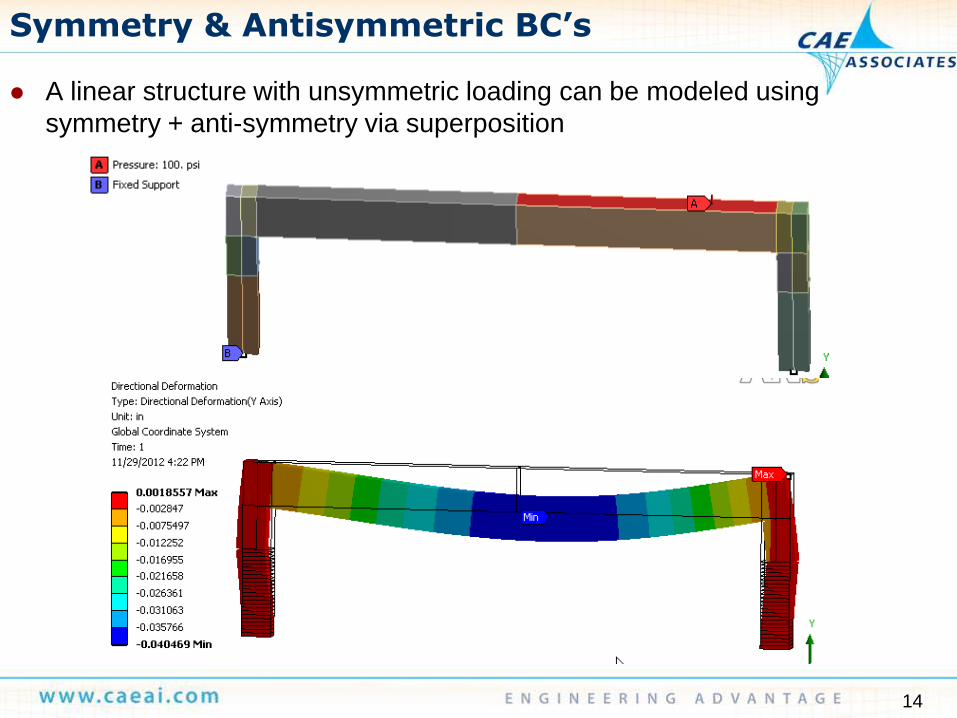
Symmetry & Antisymmetric BC’s
A linear structure with unsymmetric loading can be modeled using
symmetry + anti-symmetry via superposition
15
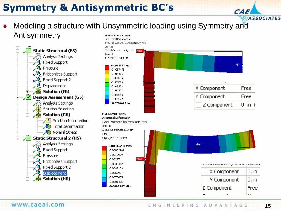
Symmetry & Antisymmetric BC’s
Modeling a structure with Unsymmetric loading using Symmetry and
Antisymmetry

16
Symmetry & Antisymmetric BC’s
Design Assessment can be used to perform the load case combination
17
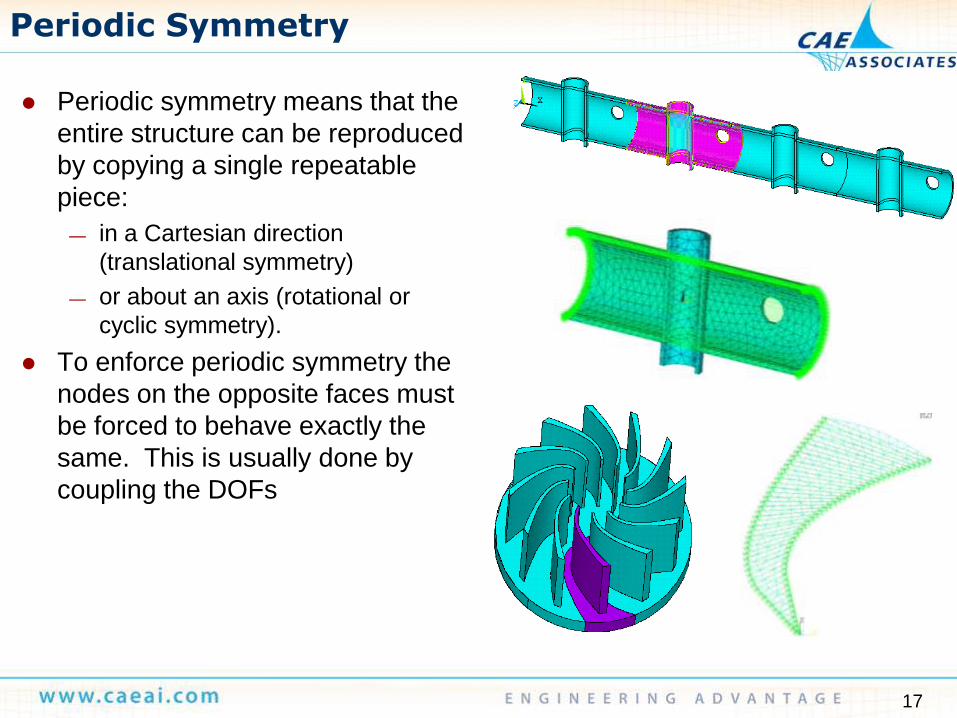
Periodic Symmetry
Periodic symmetry means that the
entire structure can be reproduced
by copying a single repeatable
piece:
— in a Cartesian direction
(translational symmetry)
— or about an axis (rotational or
cyclic symmetry).
To enforce periodic symmetry the
nodes on the opposite faces must
be forced to behave exactly the
same. This is usually done by
coupling the DOFs

18
Periodic Symmetry – New in Mech. at 14.5
Example Analysis
— Circuit Board subject to lateral acceleration loading

19
Periodic Symmetry
Example Analysis
— Linear Periodic
Symmetry
Model
Symmetry
Expansion
20
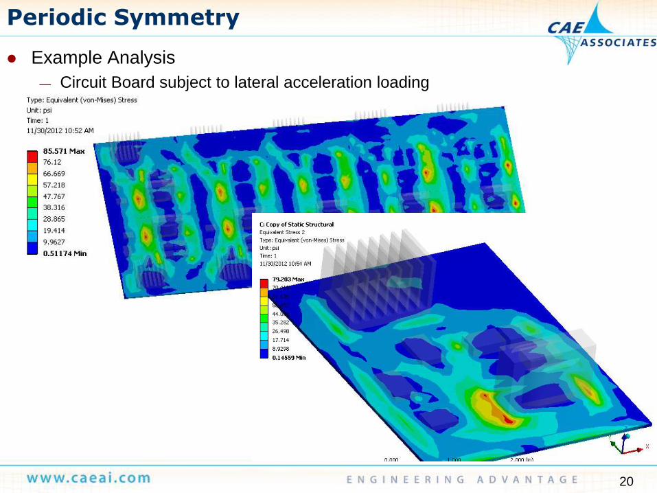
Periodic Symmetry
Example Analysis
— Circuit Board subject to lateral acceleration loading
21
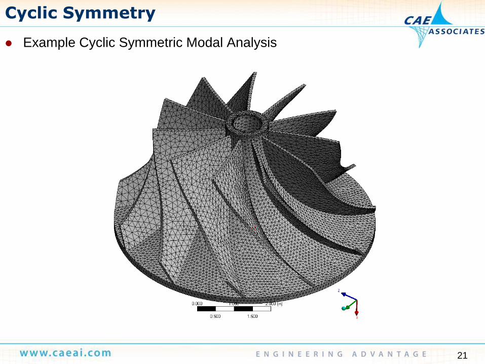
Cyclic Symmetry
Example Cyclic Symmetric Modal Analysis

22
Cyclic Symmetry
Example Cyclic Symmetric Modal Analysis

23
Cyclic Symmetry
Example Cyclic Symmetric Modal Analysis
— Modal Analysis setup defines the Harmonic Index solution(s)
24
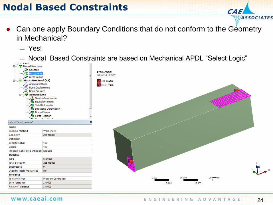
Nodal Based Constraints
Can one apply Boundary Conditions that do not conform to the Geometry
in Mechanical?
— Yes!
— Nodal Based Constraints are based on Mechanical APDL “Select Logic”
25
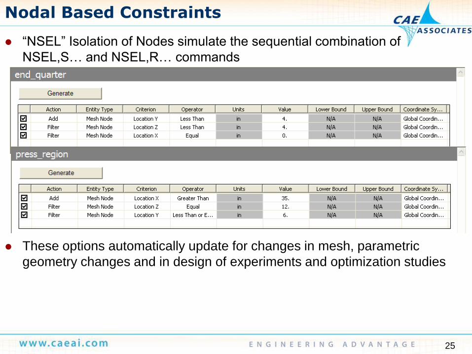
Nodal Based Constraints
“NSEL” Isolation of Nodes simulate the sequential combination of
NSEL,S… and NSEL,R… commands
These options automatically update for changes in mesh, parametric
geometry changes and in design of experiments and optimization studies

26
Nodal Based Constraints
Normal Stress – indicates region of Nodal Pressure loading
27
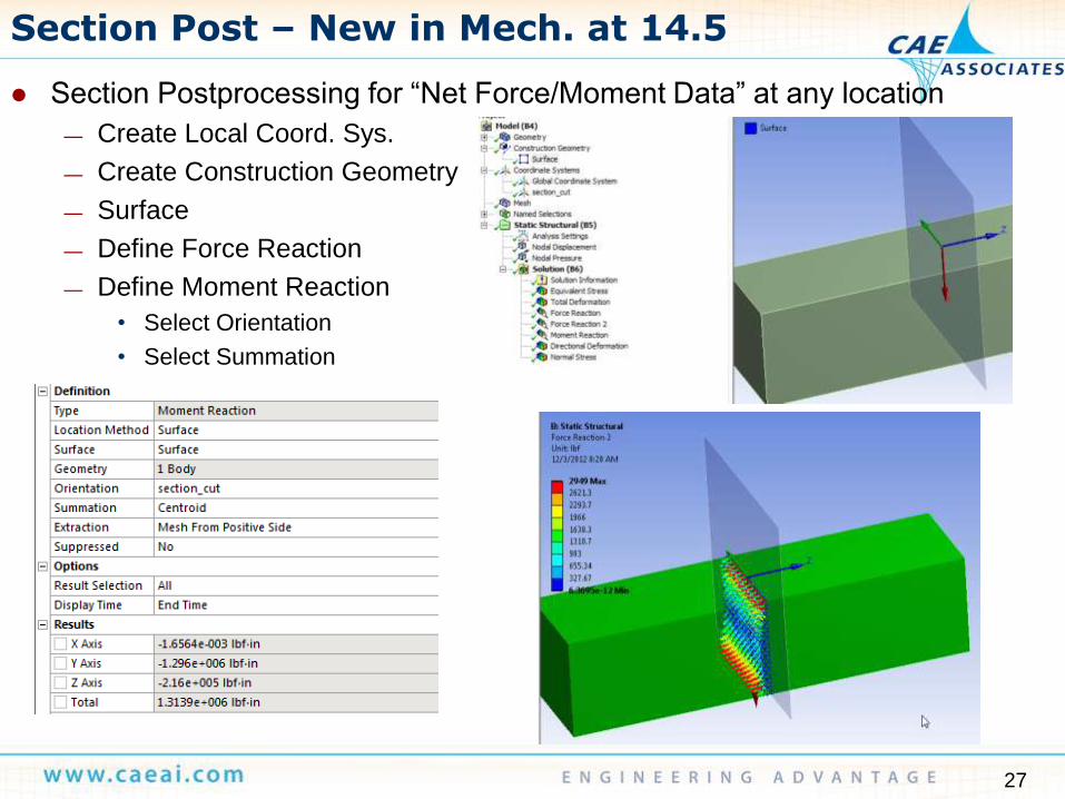
Section Post – New in Mech. at 14.5
Section Postprocessing for “Net Force/Moment Data” at any location
— Create Local Coord. Sys.
— Create Construction Geometry
— Surface
— Define Force Reaction
— Define Moment Reaction
• Select Orientation
• Select Summation
28
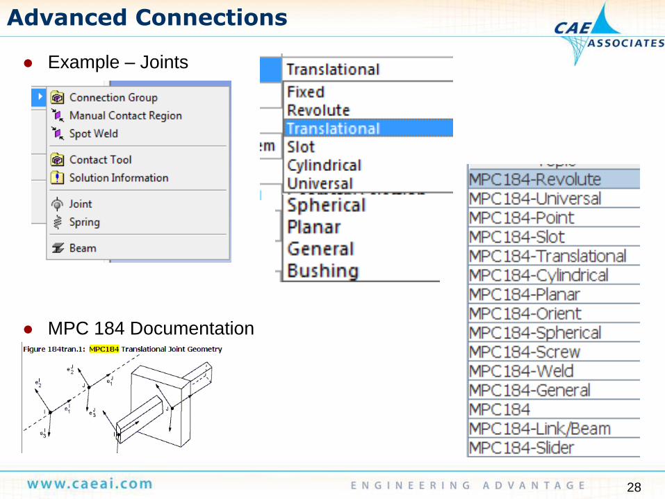
Advanced Connections
Example – Joints
MPC 184 Documentation
29
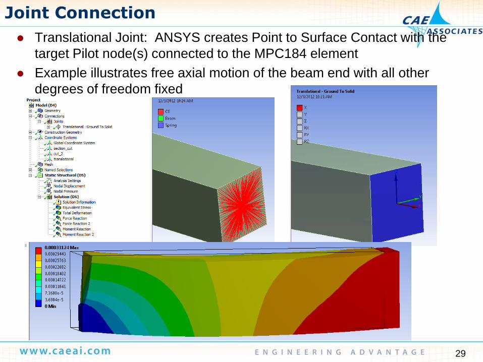
Joint Connection
Translational Joint: ANSYS creates Point to Surface Contact with the
target Pilot node(s) connected to the MPC184 element
Example illustrates free axial motion of the beam end with all other
degrees of freedom fixed