Embed Size (px)
Citation preview

Best Practices for
Building and Working Safely on Ice Covers in Ontario
ihsa.ca

Best Practices for Building and Working Safely on Ice Covers in Ontario
ii
The contents of this publication are for general information only. This publication should not be regarded or relied upon as a definitive guide to government regulations or to safety practices and procedures. The contents of this publication were, to the best of our knowledge, current at the time of printing. However, no representations of any kind are made with regard to the accuracy, completeness, or sufficiency of the contents. The appropriate regulations and statutes should be consulted. In case of any inconsistency between this document and the Occupational Health and Safety Act or associated regulations, the legislation will always prevail. Readers should not act on the information contained herein without seeking specific independent legal advice on their specific circumstance. The Infrastructure Health & Safety Association is pleased to answer individual requests for counselling and advice.
The basis for this document is the 2013 version of the Government of Alberta’s Best Practices for Building and Working Safely on Ice Covers in Alberta. The content has been used with permission from the Government of Alberta.
This document is dedicated to the nearly 500 people in Canada who have lost their lives over the past 10 years while crossing or working on floating ice.
Over the period of 1991 to 2000, there were 447 deaths associated with activities on ice. Of these, 246 involved snowmobiles, 150 involved non-motorized activity, and 51 involved motorized vehicles. Most of the deaths associated with activities on ice were related to recreational activities. (Canadian Red Cross Society, 2006)
IHSA has additional information on this and other topics.
Visit ihsa.ca or call Customer Service at 1-800-263-5024
© Infrastructure Health and Safety Association, 2014
All rights reserved. This material may be used, reproduced, stored or transmitted for non-commercial purposes. The source of this material must be acknowledged when publishing or issuing it to others. This material is not to be used, reproduced, stored or transmitted
for commercial purposes without written permission from the Infrastructure Health and Safety Association.
January 2014

Best Practices for Building and Working Safely on Ice Covers in Ontario
iii
ACKNOWLEDGEMENTS .............................................. vi
GLOSSARY .................................................................... vii
1 INTRODUCTION ...........................................................1
1.1 Background ...........................................................1
1.2 Purpose and Scope ...........................................1
1.3 Limitations ........................................................... 2
1.4 How to Use This Best Practice ................... 2
1.4.1 Use the Best Practice as a Planning Tool ................................ 2
1.4.2 Attach the Best Practice to Contracts ............................................ 2
1.4.3 Use the Best Practice to Develop an Ice Safety Plan and Standard Operating Procedures ....................... 3
1.4.4 Use the Best Practice for Hazard Recognition Training........................... 3
1.4.5 Use the Best Practice to Reduce Recreational Risk .................................. 3
2 ICE COVER HAZARDS AND FACTORS TO CONSIDER ............................................................. 4
2.1 Background ......................................................... 4
2.2 Ice Cover Type ................................................... 4
2.3 Types of Ice Cover Cracks ............................ 7
2.4 Types of Loads ................................................... 9
2.5 Load Duration .................................................. 10
2.6 Schedule and Operating Window .......... 10
2.7 Owner/Employer/Contractor Capability.............................................................. 11
2.8 Route and Site Conditions ........................... 11
2.8.1 Previous Local Experience .............. 11
2.8.2 Local Climate ......................................... 11
2.8.3 Route Selection Over Lakes, Ponds, and Muskeg Terrain ............ 12
2.8.4 River and Stream Covers ................. 12
3 ICE COVER HAZARD CONTROLS ..................14
4 ICE COVER DESIGN, MONITORING, AND MAINTENANCE ............................................16
4.1 Design Controls ................................................16
4.1.1 Gold’s Formula .....................................16
4.1.2 Effective Ice Thickness .....................19
4.1.3 Recommended Short-Term Working Loads on Ice Covers ......19
4.1.4 Effect of Sudden and Extreme Temperature Changes..................... 20
4.1.5 Stationary Loads ............................... 20
4.1.6 Lane Dimensions .................................21
4.1.7 Dynamic Effects of Vehicle Speed on Ice Covers .........................22
4.1.8 Other Load Capacity Methods ....23
4.2 Ice Cover Monitoring Controls .................23
4.2.1 Measuring and Recording Ice Thickness ........................................23
4.2.2 Monitoring Ice Cracks ......................26
4.3 Maintenance Controls ...................................27
5 DEVELOPING YOUR ICE SAFETY PLAN .....28
5.1 Ice Safety Plan .................................................28
5.2 Standard Operating Procedures for Ice Covers ....................................................28
5.2.1 Approved Use of Ice Covers .........28
5.2.2 Verifying Vehicle and Equipment Weights ...................................................29
5.2.3 Stationary Loads on Ice Covers ..............................................29
5.2.4 Minimum Distances Between Vehicles and Equipment .................29
5.2.5 Maximum Speed When Travelling on Ice Cover ....................29
5.3 Ice Cover Closure ........................................... 30
Table of ConTenTs

Best Practices for Building and Working Safely on Ice Covers in Ontario
iv
5.4 Emergency Response Planning .............. 30
5.5 Emergency Procedures ................................31
6 PERSONAL PROTECTION EQUIPMENT ......32
7 REFERENCES ............................................................33
7.1 Government References ..............................33
7.2 Technical References ....................................33
7.3 Miscellaneous References ...........................33
7.4 Photo and Illustration Credits ...................33
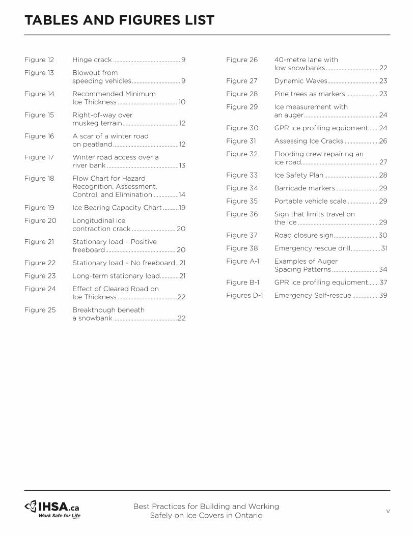
Tables
Table 1 Ice Types and Their Variability ..... 6
Table 2 Load Duration .................................... 10
Table 3 Allowable Loads in Kgs for A-Values and Effective Ice Thickness ............................................... 17
Table 4 A-Values and Hazard Controls ....18
Table 5 Minimum Ice Thickness for Lighter Loads ...............................19
Table 6 Minimum Ice Thickness for Stationary Loads up to 5,000 Kg ................................................21
Table 7 Recommended Minimum Road Dimensions .............................22
Table 8 Suggested Maximum Speed Limits ...................................... 30
Table A-1 Recommended Maximum Spacing of Auger Test Holes ......35
Table A-2 Recommended Minimum Frequency Of Auger Test Holes .............................................35
APPENDICES .................................................................. 34
Appendix A Using an Auger to Measure Ice Thickness while on Foot .............. 34
Appendix B Guide for GPR Ice Profiling ..........37
Appendix C Safety Equipment ............................38
Appendix D Emergency Procedures .................39
Appendix E Planning for Ice Covers .................42
Table A-3 Ice Cover Profile Template ...........36
Table F-1 Ice Cover Inspection Template ... 43
fIGURes
Figure 1 Clear blue lake ice .............................. 5
Figure 2 Clear blue river ice ............................. 5
Figure 3 White (snow) ice ................................ 5
Figure 4 Frazil ice (slush ice) .......................... 5
Figure 5 Jam ice .................................................... 5
Figure 6 Radial and circumferential cracks ...................... 7
Figure 7 Breakthrough on circumferential crack ........................ 7
Figure 8 Normal longitudinal cracking ....... 7
Figure 9 Longitudinal cracks – block popping out ............................. 8
Figure 10 Wet cracks ............................................. 8
Figure 11 Pressure ridge ...................................... 8
Table of ConTenTs
Tables anD fIGURes lIsT
Best Practices for Building and Working Safely on Ice Covers in Ontario
v
Figure 12 Hinge crack ........................................... 9
Figure 13 Blowout from speeding vehicles ............................... 9
Figure 14 Recommended Minimum Ice Thickness ...................................... 10
Figure 15 Right-of-way over muskeg terrain .................................... 12
Figure 16 A scar of a winter road on peatland .......................................... 12
Figure 17 Winter road access over a river bank .............................................. 13
Figure 18 Flow Chart for Hazard Recognition, Assessment, Control, and Elimination ................14
Figure 19 Ice Bearing Capacity Chart ..........19
Figure 20 Longitudinal ice contraction crack ............................ 20
Figure 21 Stationary load – Positive freeboard ............................................. 20
Figure 22 Stationary load – No freeboard ..21
Figure 23 Long-term stationary load ............21
Figure 24 Effect of Cleared Road on Ice Thickness ......................................22
Figure 25 Breakthough beneath a snowbank .........................................22
Figure 26 40-metre lane with low snowbanks ..................................22
Figure 27 Dynamic Waves .................................23
Figure 28 Pine trees as markers .....................23
Figure 29 Ice measurement with an auger ................................................24
Figure 30 GPR ice profiling equipment.......24
Figure 31 Assessing Ice Cracks ......................26
Figure 32 Flooding crew repairing an ice road ..................................................27
Figure 33 Ice Safety Plan ...................................28
Figure 34 Barricade markers ............................29
Figure 35 Portable vehicle scale ....................29
Figure 36 Sign that limits travel on the ice ....................................................29
Figure 37 Road closure sign ............................ 30
Figure 38 Emergency rescue drill ...................31
Figure A-1 Examples of Auger Spacing Patterns ............................. 34
Figure B-1 GPR ice profiling equipment.......37
Figures D-1 Emergency Self-rescue .................39
Tables anD fIGURes lIsT
Best Practices for Building and Working Safely on Ice Covers in Ontario
vi
This guideline is based on the 2013 Best Practice document from the Government of Alberta, which was created under the auspices of a multi-stakeholder advisory committee in Alberta that drew on its experience in safety, engineering, construction, and maintenance for work on ice covers.
The alberta advisory committee included the following representatives from energy, utilities, construction, forestry, and provincial and municipal governments:
Rory Ryder, Co-Chair, ATCO Electric
Ray Cislo, Co-Chair, Alberta Employment and Immigration
Sam Proskin, EBA Engineering Consultants Ltd.
Fred Baehl, Regional Municipality of Wood Buffalo
Emil Girard, Girard Enterprises
Ward Flaherty, Alberta Pacific Forest Industries
Don Hayley, EBA Engineering Consultants Ltd.
Barry Lozinsky, City of Edmonton (Parks)
Kelly McManus, LaPrairie Group Contractors Alberta Ltd.
Adele Tait, Alberta Employment and Immigration
Randall Warren, Shell Canada Energy
The Alberta committee acknowledges Don Hayley and Sam Proskin, who prepared the initial draft of the Best Practice and provided engineering input during the committee’s revisions. The committee also appreciates the valuable lessons shared by Don and Sam from working with the Tibbitt to Contwoyto Winter Road Joint Venture and Nuna Winter Road Services.
Through this collaboration, a series of ice road risk management practices have been developed and a number adapted for use in the Best Practice.
Work Safe Alberta acknowledges the following contributors to the 2013 update of this Best Practice:
Sam Proskin, NOR-EX Ice Engineering Inc.
Al Fitzgerald, NOR-EX Ice Engineering Inc.
aCknowleDGemenTs

Best Practices for Building and Working Safely on Ice Covers in Ontario
vii
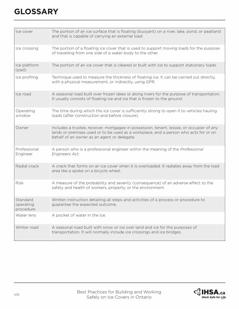
Circumferential crack
A crack that forms on an ice cover when it is overloaded. These are rounded cracks that are centered around the loaded area.
Constructor A person who undertakes a project for an owner and includes an owner who undertakes all or part of a project by himself or by more than one employer.
Deflection test A field test that determines the load capacity of an ice cover by monitoring deflection of the ice as it is progressively loaded.
Effective ice thickness
Good quality, well-bonded, clear and blue ice that is measured in an ice cover. Poor quality or poorly bonded ice should not be included in the measurement of ice thickness. White ice is considered to have 1⁄2 the strength of blue ice. Effective thickness is 100% blue ice + 50% white ice for a well-bonded layer.
Employer A person who employs one or more workers or contracts for the services of one or more workers and includes a contractor or subcontractor who performs work or supplies services and a contractor or subcontractor who undertakes with an owner, constructor, contractor, or subcontractor to perform work or supply services.
Freeboard The distance measured from the ice surface to the stationary water level in the hole below the surface. Ice is less dense than water, so it floats.
Global Positioning System (GPS)
A radio navigation system that allows land, sea, and airborne users to determine their exact location, velocity, and elevation 24 hours a day, in all weather conditions, anywhere in the world.
Gold’s Formula A formula developed by Dr. Lorne Gold to calculate the allowable load that can be placed on a floating ice cover.
Gross Vehicle Weight (GVW)
For the purpose of this Best Practice, this is the total weight of a road vehicle when loaded (i.e., it includes the weight of the vehicle itself plus fuel, freight, passengers, attachments, and equipment). Experience has shown that weighing the vehicle on a scale is the most accurate way to determine the GVW.
Ground Penetrating Radar (GPR)
A geophysical technique that uses radio frequency energy to image the earth’s subsurface. It emits microwave electromagnetic radiation and then detects the reflections from land formations or objects it contacts below the surface.
Hazard A hazard is a thing or situation with the potential to harm a worker.
Hazard assessment
An assessment of the worksite to identify existing and potential hazards before work begins at the worksite or prior to the construction of a new worksite.
Ice bridge A constructed ice crossing over a river or stream.
GlossaRy
Best Practices for Building and Working Safely on Ice Covers in Ontario
viii
GlossaRy
Ice cover The portion of an ice surface that is floating (buoyant) on a river, lake, pond, or peatland and that is capable of carrying an external load.
Ice crossing The portion of a floating ice cover that is used to support moving loads for the purpose of travelling from one side of a water body to the other.
Ice platform (pad)
The portion of an ice cover that is cleared or built with ice to support stationary loads.
Ice profiling Technique used to measure the thickness of floating ice. It can be carried out directly, with a physical measurement, or indirectly, using GPR.
Ice road A seasonal road built over frozen lakes or along rivers for the purpose of transportation. It usually consists of floating ice and ice that is frozen to the ground.
Operating window
The time during which the ice cover is sufficiently strong to open it to vehicles hauling loads (after construction and before closure).
Owner Includes a trustee, receiver, mortgagee in possession, tenant, lessee, or occupier of any lands or premises used or to be used as a workplace, and a person who acts for or on behalf of an owner as an agent or delegate.
Professional Engineer
A person who is a professional engineer within the meaning of the Professional Engineers Act.
Radial crack A crack that forms on an ice cover when it is overloaded. It radiates away from the load area like a spoke on a bicycle wheel.
Risk A measure of the probability and severity (consequence) of an adverse effect to the safety and health of workers, property, or the environment.
Standard operating procedure
Written instruction detailing all steps and activities of a process or procedure to guarantee the expected outcome.
Water lens A pocket of water in the ice.
Winter road A seasonal road built with snow or ice over land and ice for the purposes of transportation. It will normally include ice crossings and ice bridges.

Best Practices for Building and Working Safely on Ice Covers in Ontario
1
SECTION 1 INTRODUCTION
1.1 baCkGRoUnDSeveral generations of Canadians have used river, lake, and sea ice covers to travel to their destinations, to deliver freight, to fish and hunt and, more recently, to enjoy the recreational opportunities leisure time affords them. The earliest of these hardy ice travellers used foot, snowshoes, skis, dogsleds, and horse and sleigh.
Pioneers like Svein Sigfusson in Manitoba in the 1940s and John Dennison in the Northwest Territories in the 1960s demonstrated that ice roads were viable alternatives for re-supplying camps and moving goods to remote communities. Today, ice roads and winter roads are constructed in most Canadian provinces and territories to provide temporary access to communities, worksites and recreational areas.
Working, travelling, and parking on the frozen surface of ponds, lakes, and rivers should be undertaken as a planned activity that recognizes and addresses the hazards associated with the ability of the ice cover to safely support the load.
In 25 years of hauling freight we lost three men through the ice—a record that might look good in cold actuarial tables but was still a hard reality that caused great lasting sadness to all who did survive. Three deaths, even among thousands of men, inevitably left a tragic tinge on the successes of our company.
Sigfusson’s Roads, Svein Sigfusson, 1992
Dog and man watched it crawling along over the ice. Suddenly, they saw its back end drop down, as into a rut, and the gee-pole, with Hal clinging to it, jerk into the air. Mercedes’ scream came to their ears. They saw Charles turn and make one step to run back, and then a whole section of ice give way and dogs and humans disappear. A yawning hole was all that was to be seen. The bottom had dropped out of the trail.
The Call of the Wild, Jack London, 1903
seCTIon 1 – InTRoDUCTIon
1.2 PURPose anD sCoPeThis Best Practice has been developed to provide a summary of current practices for construction and operation of transportation roadways and working platforms that rely on floating ice for structural adequacy. The focus is on advice that provides effective over-ice operations while ensuring that a standard of care necessary to protect worker safety is the highest priority. The Best Practice covers the basic steps for planning, design, construction, operation, and closure of an over-ice project.
This Best Practice was developed to assist employers and constructors in protecting the health and safety of workers. In general this requires a risk-based approach, through hazard identification, assessment, elimination, and control. This process is outlined on the next page.
The Occupational Health and Safety Act (OHSA) and associated Regulations for Construction Projects (O. Reg. 213/91) set out minimum legal requirements governing exposure to various health and safety hazards. The OHSA applies to a broad range of workers while the Regulations for Construction Projects applies to workers on construction projects.
1. Recognize the hazard: Identify existing and potential hazards before work begins.
2. assess the hazard
i. Assess the severity of the consequence arising from the hazard in terms of harm to workers, equipment, or the environment.
ii. Assess the likelihood of the consequence arising from the hazard.
iii. Assess and prioritize the hazards based on the risk.

Best Practices for Building and Working Safely on Ice Covers in Ontario
2
SECTION 1 INTRODUCTION
3. Control or eliminate the hazard
i. Eliminate the hazard
ii. Employ engineered controls
A. Design controls
B. Monitoring controls
C. Maintenance controls
iii. Implement administrative controls.
iv. Establish requirements for the proper selection, use, and maintenance of personal protective equipment (PPE).
Potential hazards need to be identified and steps taken to eliminate the hazards or control them to a level that will not endanger worker health and safety while being easily understood and applied by the worker.
This Best Practice applies to work where short-term loads (less than two hours duration) are supported by a freshwater floating ice cover. Examples of common work on ice covers:
•
• Traversing ice covers by foot or snowmobile
• Preparing ice covers for recreational use
• Profiling an ice crossing from a truck or tracked vehicle
• Driving vehicles over lake or river ice crossings
• Monitoring ice crossings during winter road construction and operations or during construction of ice pads.
1.3 lImITaTIonsThis Best Practice was developed based on experience with ice covers comprising natural, fresh water as well as water used to flood ice for enhanced thickening. There are field conditions that do not fit that criteria and are not covered within this Best Practice. These conditions require the expertise of a professional engineer experienced in ice mechanics and may include but are not limited to:
•
• Loads on sea ice covers or ice containing dissolved solids
•
• Loads on ice covers that are floating on industrial water ponds (such as tailings ponds)
•
• Vehicles with more than eight axles or a GVW greater than 63,500 kg
•
• Loads with a significant dynamic or vibrational component such as a heavy Caterpillar tractor with steel grouser bars.
1.4 How To Use THIs besT PRaCTICe
Use of this Best Practice may increase knowledge that could improve the standard of care that is exercised when planning and carrying out work activities on a floating ice sheet. The safety of workers is of paramount importance, and it is recognized that judging safety when working on a floating ice sheet takes specialized expertise. However, the full value of the Best Practice can only be achieved if it is implemented at appropriate stages within any project plan. The following commentary provides suggestions as to where it can be used most effectively.
1.4.1 Use the best Practice as a Planning ToolThe Best Practice should be consulted early in the planning process. It identifies those steps that must be taken for the work to be done safely and effectively. When several alternatives are being considered concerning the use of ice covers for a working platform, the Best Practice can identify what limitations the ice cover may impose on the work. These considerations may include load limitations, length of season, and safety monitoring.
1.4.2 attach the best Practice to ContractsEmployers must ensure compliance with section 25(2)(h) of the Occupational Health and Safety Act. One way to achieve this is for employers preparing for activities on floating ice to establish and implement a plan to ensure the health and safety of workers. In some instances, that plan could include a contractual obligation to follow this Best Practice.

Best Practices for Building and Working Safely on Ice Covers in Ontario
3
INTRODUCTIONSECTION 1
1.4.3 Use the best Practice to Develop an Ice safety Plan and standard operating ProceduresMany larger constructors/employers are becoming registered users of the International Organization for Standardization’s (ISO) quality assurance standards.
Within that system is a requirement to document “standard operating procedures.” This Best Practice could form the basis for developing in-house procedures for firms that carry out activities on floating ice.
1.4.4 Use the best Practice for Hazard Recognition TrainingThis Best Practice can form the basis of hazard recognition training for workers preparing for activities on floating ice. The Occupational Health and Safety Act places a duty on employers to provide information, instruction, and supervision to a worker to protect the health or safety of the worker.
1.4.5 Use the best Practice to Reduce Recreational RiskThis Best Practice has been developed primarily for employers, constructors, and workers. However, it may also be helpful to recreational users who are considering travelling over ice covers or participating in activities on them, for example, ice fishing.

Best Practices for Building and Working Safely on Ice Covers in Ontario
4
ICE COVER HAZARDS AND FACTORS TO CONSIDERSECTION 2
2.1 baCkGRoUnDPlanning for operations over floating ice covers requires a clear understanding of how the ice sheet must function to ensure a successful and safe project. This is especially important for constructors or employers who have no previous experience building ice covers. The following operational parameters must be identified at the outset:
•
• load duration The period of time that the load will be stationary on the ice cover.
•
• Ice cover type Freshwater lake ice, river ice, local flood ice, transported flood ice, or peatland ice.
•
• load weights The number and types of vehicles and equipment and their maximum gross vehicle weights (GVWs); this may also include loads imposed by foot traffic for special types of work.
•
• schedule and operating window Timing of the start of construction and start of work on the ice cover as well as the operating window required for the work.
•
• employer capability Employer experience, equipment availability, and worker training.
•
• Hazard controls Controls that reduce either the consequence and/or the likelihood of a hazard; choice of controls depends on the risk level, degree of operator control over the use of the cover, and the user’s exposure.
•
• Route selection constraints Site access, hydrology, and site permits.
It is also important to consider who will be exposed to the hazards associated with the ice cover: the construction crew, vehicle operators, and members of the public. Normally, the construction crew who builds the ice road faces the greatest risk because crew members go out on the ice with minimal information at the start of the season. This can be dealt with by adhering to controls implemented during the pre-construction and construction phases. Following the construction phase, vehicle operators use the roads to haul loads. Although they may be hauling the heaviest loads, the hazards they are exposed to are minimized through use of the hazard controls.
Members of the public may be at risk if they attempt to access an ice cover when it has been closed by the operator and the operational controls are no longer in place. Consequently, it may be necessary to develop other controls to deal with hazards to the public.
2.2 ICe CoVeR TyPeIce type considers how the ice forms, a factor that affects the ice cover’s strength, variability, and quality. Freshwater ice, often referred to as blue ice, forms naturally on lakes and rivers and can be similar in strength across all surfaces (Figure 1).
Rivers are more dynamic and subject to currents, so are consequently more variable (Figure 2).
Natural flood (white) ice, which occurs when water floods the surface of natural ice, can be of lesser quality due to the presence of snow and unfrozen water (Figure 3).
Constructed flood ice built by qualified personnel with good practices can generate ice that is comparable to freshwater blue ice in strength and uniformity. The ice types with the least strength and quality are frazil ice (Figure 4) and jam ice (Figure 5).
seCTIon 2 – ICe CoVeR HaZaRDs anD faCToRs To ConsIDeR

Best Practices for Building and Working Safely on Ice Covers in Ontario
5
SECTION 2ICE COVER HAZARDS AND FACTORS TO CONSIDER
ICE TYPES (Ashton 1985)
figure 1: figure 2: Clear blue lake ice Clear blue river ice
Blue ice: Ice that grows below the layer of surface ice under calm conditions. It usually forms in vertical, columnar crystals that contain few air bubbles. It appears to be blue because it’s clear enough to see the water underneath it.
figure 3: white (snow) ice
White ice (snow ice): Ice that forms on top of the surface ice by natural or man-made flooding of snow. It’s white because it contains a significant number of air bubbles. White opaque ice, or snow ice, is normally considered to be only half as strong as blue ice.
Peatland ice cover or frost depth (depth at which the peat is well bonded by ice) poses a greater risk because it can be overlooked. The depth of frost depends on the air temperature, composition/depth of peat or mineral soil, and the type of ground cover. The strength of saturated frozen peat depends on the peat’s composition, water content, and temperature.
figure 4: frazil ice (slush ice)
Frazil ice (slush ice): Ice made up of disk-shaped ice particles that form and join together in agitated water. It is usually found in rivers or streams with turbulent waters.
figure 5: Jam ice
Jam ice: An accumulation of ice that often forms on rivers or streams. It occurs when currents move pieces of ice cover to an area where they accumulate and freeze together to form very rough and thick ice covers.
The ice cover type is a key component when conducting a hazard assessment and identifying appropriate hazard management. Higher loads could be used on reliable freshwater lake ice that has good ice monitoring data and a high level of operational controls.

Best Practices for Building and Working Safely on Ice Covers in Ontario
6
SECTION 2
*Masterson, D.M., Invited Paper: State of the art of ice bearing capacity and ice construction, Cold Regions Science and Technology (2009), doi:10.1016/j.coldregions.2009.04.002
ICE COVER HAZARDS AND FACTORS TO CONSIDER
Table 1: ICe TyPes anD THeIR VaRIabIlITy
Ice Type Ice Thickness Quality and strength
Freshwater lake (blue) ice Low variability over an area Uniform ice quality
Higher strength due to low variability
River (blue) ice Medium to high variability over an area
More prone to losing underside ice thickness to currents
Fairly uniform ice quality
Variable strength due to variable ice thickness
Natural overflow (white) ice High variability over an area Overflow ice, caused by natural water overflow onto the ice surface, usually contains high air content and should not be relied upon in calculating effective ice thickness. White opaque ice, or snow ice is normally considered to be only half as strong.
Constructed flood ice Good practices build uniform ice Uniformity and quality depend on construction practices. If ice is constructed using sound construction practices, which may include pumping fresh water directly onto the surface of bare ice (flooding), then this ice, once completely frozen and inspected, can be considered as having similar strength to freshwater lake ice.*
Peatland ice High variability Strength is highly variable due to water chemistry and temperature.
Frost depth depends on air temperature, peat composition/ thickness and ground cover.
Requires specialized analyses and investigation of ice conditions.

Best Practices for Building and Working Safely on Ice Covers in Ontario
7
SECTION 2
2.3 TyPes of ICe CoVeR CRaCksAny ice cover will have cracks caused by thermal contraction or movements in the ice cover. Cracks do not necessarily indicate a loss in the load bearing capacity of the ice, except when they are wet or they are radial or circumferential cracks associated with overloading the ice.
Eight mechanisms that cause cracks in ice covers are:
•
• Excessive loads
•
• Differences in ice thickness and buoyancy
•
• Snowbanks
•
• Thermal contraction of ice
•
• Thermal expansion of ice
•
• High winds
•
• Water level fluctuations
•
• Dynamic waves.
figure 6
Plan view of radial (spoke-like) and circumferential (round) cracks
forming on overloaded ice
Load-induced cracks are those caused by moving or stationary loads that are too heavy for the ice. Field studies have shown that gradually overloading the ice leads to three stages of cracking, as shown in Figure 6:
•
• Radial cracks may be observed originating from the centre of a load, like spokes on a bicycle wheel. This usually occurs at about one half of the failure load. Radial cracks are a warning that the ice is overloaded and the load should be removed immediately.
•
• Circumferential cracks are those that start forming a circle around the load. Circumferential cracks
circle the load like the ripples caused by a stone tossed in a pond. They are a warning that the load is about to break through the ice and personnel should be evacuated from the loaded area.
•
• Circumferential cracks that connect with radial cracks to form pie-shaped wedges indicate the ice has failed at this point and the load can fall through at any time, as experienced by the D10 Caterpillar operator in Figure 7.
figure 7
Breakthrough of a D10 Caterpillar tractor following formation of a circumferential crack pattern
Thicker ice may provide a warning, but thinner ice can fail so rapidly that radial cracking cannot be relied on for any warning.
figure 8
Normal longitudinal cracking caused by buoyancy of the thickened ice over the 20-metre-wide travel lane
Differences in ice thickness and buoyancy cause longitudinal cracks to form along the road in the middle of the cleared lane (Figure 8). As discussed in
ICE COVER HAZARDS AND FACTORS TO CONSIDER

Best Practices for Building and Working Safely on Ice Covers in Ontario
8
SECTION 2ICE COVER HAZARDS AND FACTORS TO CONSIDER
Section 4.1.6, the thicker ice in the cleared lane rises above the ice that’s depressed beneath the heavy snow banks. This causes an upward bending of the ice cover that reaches a maximum in the middle of the cleared lane. When the bending becomes severe enough, cracks form on the surface of the ice to relieve the stresses. In most cases, the cracks do not extend deep enough to create a breakthrough hazard.
Sometimes several longitudinal cracks can intersect on the surface. Under the right conditions, a shallow piece of ice can pop out (Figure 9). These pop-outs, like potholes on regular roads, are a hazard because they can cause vehicle damage.
figure 9
Longitudinal cracks that have intersected and caused a
block of ice to pop out
Cracks can occur under snowbanks that are built by snow piled into windrows along the edge during snow clearing, as shown in Figure 10. These cracks form because the snow depresses and bends the ice cover underneath the snow. Cracks are also more likely to form because the ice cover is thinner here due to the insulating effect of the snow. Most of these cracks start on the bottom and extend upward, but they usually do not reach the surface. However, some of these cracks extend to the top of the cover, creating a wet crack that is a hazard.
These cracks should be monitored and all traffic kept clear of these areas until these flooded areas have re-frozen. Any activities in the area of snowbanks should be conducted with great care. Consideration should be made in the initial ice design to create enough working space on the ice sheet so that snowbanks do not need to be moved once established. Additional guidance for snow clearing in the vicinity of snowbanks is provided in Section 4.1.6.
figure 10
Evidence of wet cracks underneath a snowbank from water that flowed through the cracks and froze on the surface
Thermal contraction cracks are caused when ice shrinks due to significant cooling. These cracks are usually distributed randomly over the ice and spaced well apart. Snow removal tends to promote thermal contraction cracks because it exposes the surface to rapidly changing air temperatures. Thermal contraction cracks are usually dry but should be monitored because they can become wet cracks if they are subject to further contraction or heavy loads.
figure 11
Pressure ridge about two metres high and several hundred metres long that formed adjacent to a road over lake ice
Thermal expansion can lead to pressure ridges, which are portions of the ice sheet that have moved together to form ridges that can rise up to three metres above the surface and extend for hundreds of metres (Figure 11). These ridges often occur after the formation of thermal contraction cracks that have filled with water and refrozen. If there is a sudden warming of the ice, then the ice sheet

Best Practices for Building and Working Safely on Ice Covers in Ontario
9
SECTION 2ICE COVER HAZARDS AND FACTORS TO CONSIDER
expansion is accommodated by upward movements of ice at weak (thin) locations in the ice sheet. These tend to form on larger lakes (several kilometres across) where the thermal expansion effect can accumulate over large distances.
Pressure ridges can challenge operators because they can be areas of reduced bearing capacity or sources of water, or be difficult to cross. Pressure ridges can recur over several years and local knowledge may help in identifying potential pressure ridge locations. Upheaved pressure ridges should be avoided due to their unpredictable nature. Pressure ridges should be well marked if in the vicinity of ice crossing alignment and the travel path should be re-routed.
Wind cracks often result in ridge formations that can be parallel or perpendicular to the shoreline. Ice covers should be inspected for wet cracks after experiencing sustained winds of 55 km/h or more early in the season. Wet cracks must either be repaired or avoided by relocating the activities on the ice cover.
Water level fluctuation cracks usually occur in rivers but can occur in lakes when lake levels change. Cracks can also occur in rivers downstream of dams that control water levels. These cracks are almost always wet, tend to follow the shoreline and occur around grounded ice features. In severe cases, the ice cover can separate completely and form a significant drop (Figure 12). It is best to avoid areas of grounded ice features that have water level fluctuation cracks around them. These cracks should be checked before permitting loads to cross them.
figure 12
Hinge crack that became a break along a lake shoreline when the water level dropped
Dynamic waves caused by vehicles travelling too quickly over the ice can cause ruptures in the ice where it is thin or weak. The most common form of rupture is the crown-shaped blowout (Figure 13). These can be two to 20 metres across but tend to occur away from the thickened ice and in thinner ice areas.
figure 13
Blowout caused by speeding vehicles creating dynamic waves
that release their energy at weak areas in the ice
2.4 TyPes of loaDsLoad types consider the anticipated demand on the ice cover in terms of the number and weight of the loads (Figure 14). Five load types are identified:
1. Foot traffic (total load less than 120 kg) such as workers carrying out initial testing of the ice
2. Snowmobiles (total load less than 500 kg) used at the beginning of the season to pioneer a trail for ice road clearing or for one-time access to a site
3. Light vehicle traffic (total load less than 5,000 kg) to move personnel and light equipment to a worksite across an ice cover that has been cleared of snow to promote ice growth
4. Construction vehicles/equipment including amphibious vehicles (total load less than 22,500 kg) used to clear snow and build ice
5. Heavy vehicle traffic (22,500 to 63,500 kg) for moving heavier equipment across an ice cover that has been cleared/built for this purpose.
Heavier and more frequent loads require greater hazard controls to offset the higher risk of ice failure.

Best Practices for Building and Working Safely on Ice Covers in Ontario
10
SECTION 2ICE COVER HAZARDS AND FACTORS TO CONSIDER
figure 14: Recommended minimum Ice Thickness for blue Ice
2.6 sCHeDUle anD oPeRaTInG wInDowScheduling of ice cover operations depends on ice quality and strength, weather conditions, and traffic requirements.
Weather conditions usually dictate the timing of construction start-up. Air temperatures and snow cover affect the growth of the ice cover (extent of cover, thickness, and stability). Climatic data and local ice conditions are important for evaluating the probable operating period.
A project with a high number of vehicle crossings could require that an ice cover remain open for as
2.5 loaD DURaTIonLoad duration must be considered because it affects the success or failure of the ice cover and the way the carrying capacity is analyzed (Table 2). Vehicles moving across the ice cover are analyzed using a different design approach than is used for stationary (immobile/parked) loads such as a drill rig or disabled vehicle sitting on the ice cover.
This Best Practice provides some specific recommendations for slow-moving vehicles and short-duration (less than two hours) stationary loads on ice covers. For medium-duration loads, some preliminary recommendations are provided; heavier stationary loads require recommendations from a professional engineer.
many days as possible, so achieving an early start can be very important. For projects with a low number of vehicle crossings, a long ice cover season is not as critical; therefore, identifying a few weeks within a season to safely move a few heavy loads may be the priority.
A preliminary schedule needs to be established to determine what seasonal conditions or constraints exist.
Table 2: loaD DURaTIon
load Duration observed effects Design options for Carrying Capacity
Slow-moving loads with stops of short duration (less than two hours)
Initial cracking of the ice cover Refer to Section 4
Stationary loads of medium duration (less than seven days)
Ice deflection that approaches freeboard
Special analyses in Section 4.1.5
Stationary loads of longer duration (seven or more days)
Excessive creep deflection – water on ice
Professional engineer must review
Note: Vehicle spacing is a factor that is addressed in Sections 5.2.3 and 5.2.4.

Best Practices for Building and Working Safely on Ice Covers in Ontario
11
SECTION 2ICE COVER HAZARDS AND FACTORS TO CONSIDER
2.7 owneR/emPloyeR/ ConsTRUCToR CaPabIlITyExperienced owners/constructors/employers may take the overall responsibility for planning, preparing, designing, building and operating ice covers. The owner/constructor/employer’s experience can therefore be critical in selecting the route, equipment, and people required to build and operate a successful ice cover. Owners/constructors/employers of the ice cover may maintain overall project control, but the constructor/employer’s role remains crucial to the successful construction and operation of the ice cover.
The following attributes should be considered when reviewing constructor/employer capabilities:
•
• Experience in building similar ice covers
•
• Experience in building ice covers in the same region
•
• Experience of key staff
•
• Availability of equipment for construction
•
• Health and safety plan for working on ice
•
• Demonstrated knowledge and understanding of this Best Practice
•
• Knowledge of ice bearing capacity and factors affecting it.
2.8 RoUTe anD sITe ConDITIons
The use of floating ice covers is most frequently associated with seasonal transportation facilities such as winter roads or ice bridges. Winter roads make use of ice covers on lakes and peatlands that will not support traffic loading unless frozen. Winter roads and ice bridges can improve or provide access to remote communities or allow seasonal access for construction or re-supply at remote sites. Use of ice covers for seasonal transportation purposes requires route planning and recognition of certain site features that will directly influence the application of this Best Practice. Those features that must be recognized and evaluated in the planning process are discussed in this section.
2.8.1 Previous local experienceThe first step in planning for use of an ice cover is to thoroughly evaluate previous use of ice covers along the route or at the site under consideration. Much of the technology for understanding ice behaviour has evolved from field observations and experience. Contractors with prior experience with similar ice covers at the site or at nearby sites can provide field experience that is valuable. However, caution is still advised when considering field experience because water levels, weather, and ice conditions can vary from year to year. Contractors may have to alter their methods and equipment to adapt to changes in ice conditions that differ significantly from what they’re accustomed to seeing.
2.8.2 local ClimateIce growth and capacity is directly linked to the climatic conditions at the site during the time of construction activities. The parameters of importance are mean daily temperature and snow cover. Local climatic variations may have to be considered when applying temperature and snowfall data from a meteorological station near to the project location.
Current and historical data for weather stations throughout Ontario is available from Environment Canada’s Climate Data Online website: www.climate.weatheroffice.ec.gc.ca/
Throughout Northern Canada, warming trends caused by climate change are affecting the function and design of seasonal infrastructure that relies on frozen conditions. The greatest changes are being documented during the winter months in the northernmost part of the provinces and territories. The last published Canadian Climate Normals, a 30-year running average of climatic data to which any individual year is compared, are for the period 1971 to 2000. The last 10 years have included three of the warmest winters on record. What may be of greater significance is the range of variability currently observed between a “warm year” and a “cold year.” This variability, coupled with the substantial changes in precipitation that accumulates as snow on the early season ice surface, can impede normal ice growth.

Best Practices for Building and Working Safely on Ice Covers in Ontario
12
SECTION 2ICE COVER HAZARDS AND FACTORS TO CONSIDER
2.8.3 Route selection over lakes, Ponds, and muskeg TerrainThe following factors must be considered at the planning phase when lake ice is used in a winter road route alignment:
•
• access onto and off the lake ice surface This must be a technically and environmentally acceptable route. Avoid river and stream outlets/inlets as the lake ice cover near them is usually unreliable.
•
• water depth along the chosen lake crossing A rough bottom condition caused by unforeseen shoals and sandbars can initiate lake ice fractures and should be avoided wherever practical.
•
• overall water depth along the route A route that follows continuous deep water is often the most effective alternative, particularly for heavy loads that require severe speed restrictions to manage the ice deflections that occur from movement in the ice and water.
Routing a winter road across frozen peatlands can also expose workers to ice failure hazards that are often overlooked. Open peatland or muskeg terrain can include a mosaic of bog and fen landforms, as shown in Figures 15 and 16. The fens can be ponds that are hidden by a thin layer of floating live vegetation. There are documented cases of construction equipment breaking through thin frozen peat unexpectedly, resulting in operator fatalities
Planning winter routes over peatland requires the same caution as planning routes over rivers. A terrain assessment carried out by a geomorphologist or geotechnical engineer using stereo aerial photos will identify areas at risk. Aerial photography and summer aerial views can provide important information. This assessment should be verified by route reconnaissance, and appropriate plans should be developed to monitor the thickness of ice or frozen peat before construction equipment is deployed.
figure 15
Right-of-way over muskeg terrain
Muskeg terrain is sensitive and there may be requirements to minimize damage from a winter road. A scar of a winter road across this type of terrain is shown in Figure 16.
figure 16
A scar of a winter road across peatland
2.8.4 River and stream CoversRiver ice is less predictable than lake ice. It is affected by fluctuating water levels, under-ice currents, and bottom conditions that can shift from year to year. Specific route or site factors that must be carefully considered when planning ice bridges across rivers include:
•
• Choose the best site Where several crossing sites are considered practical, choose the site that has the deepest water and most uniform bottom conditions. This is often the widest crossing site, unlike an appropriate crossing for a structural bridge.

Best Practices for Building and Working Safely on Ice Covers in Ontario
13
SECTION 2ICE COVER HAZARDS AND FACTORS TO CONSIDER
Be cautious of the proximity of islands because they are features that are commonly created by active erosion or deposition, signifying channel shifting and unpredictable currents.
•
• be aware of variations in ice thickness The presence of naturally drifting snow on river ice combined with under-ice currents can result in highly variable ice thickness. These conditions require a high degree of vigilance to confirm and monitor ice growth and variations in ice thickness. It is recommended to have ice thickness verified with accuracy by technical aids such as Ground Penetrating Radar (GPR) profiling.
•
• map the river bottom Sand bars and other features that determine bottom topography can affect ice cover thickness and extent. River bottom topography should be mapped with either manual water depth measurements or with geophysical methods (sonar or GPR).
•
• ensure river bank is stable Locations for access to and from the ice surface should be chosen where river bank stability is considered acceptable from hydrological, geotechnical and environmental perspectives.
•
• be aware of other factors Water level under the ice can be affected during the operating period by factors that are not common but on occasion have been known to result in unsafe conditions. For example, river estuaries near tidewater affect ice bridges on the James Bay Winter Road in Ontario. River flow data can be obtained from the Water Survey of Canada: http://www.ec.gc.ca/rhc-wsc/
figure 17
Winter road access over a river bank
Best Practices for Building and Working Safely on Ice Covers in Ontario
14
ICE COVER HAZARD CONTROLSSECTION 3
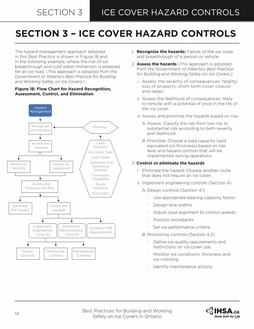
The hazard management approach adopted in this Best Practice is shown in Figure 18 and in the following example, where the risk of ice breakthrough and cold water immersion is assessed for an ice road. (This approach is adopted from the Government of Alberta’s Best Practice for Building and Working Safely on Ice Covers.)
figure 18: flow Chart for Hazard Recognition, assessment, Control, and elimination
1. Recognize the hazards: Failure of the ice cover and breakthrough of a person or vehicle.
2. assess the hazards (This approach is adopted from the Government of Alberta’s Best Practice for Building and Working Safely on Ice Covers.)
i. Assess the severity of consequences: fatality; loss of property; short-term cover closure and repair.
ii. Assess the likelihood of consequences: likely to remote with a potential of once in the life of the ice cover.
iii. Assess and prioritize the hazards based on risk:
A. Assess: Classify the risk from low risk to substantial risk according to both severity and likelihood.
•B. Prioritize: Choose a load capacity (and equivalent ice thickness) based on risk level and hazard controls that will be implemented during operations.
3. Control or eliminate the hazards
i. Eliminate the hazard: Choose another route that does not require an ice cover.
ii. Implement engineering controls (Section 4)
A. Design controls (Section 4.1)
•
• Use appropriate bearing capacity factor.
•
• Design lane widths.
•
• Adjust road alignment to control speeds.
•
• Position snowbanks.
•
• Set ice performance criteria.
B. Monitoring controls (Section 4.2)
•
• Define ice quality requirements and restrictions on ice cover use.
•
• Monitor ice conditions: thickness and ice cracking.
•
• Identify maintenance actions.
seCTIon 3 – ICe CoVeR HaZaRD ConTRols
Recognize the Hazards
Hazard Management
Planning
Load Duration
Ice Cover Type
Load Types
Schedule and Operating Window
Contractor Capability
Route Selection
End Users
Assess the Hazards
Assess its Severity
Eliminate the Hazard
ImplementEngineering
Controls
ImplementAdministrative
Controls
Establish PPERequirements
Control the Hazards
DesignControls
Monitoring Controls
Maintenance Controls
Assess andPrioritize the Risk
Assess itsLikelihood

Best Practices for Building and Working Safely on Ice Covers in Ontario
15
ICE COVER HAZARD CONTROLSSECTION 3
C. Maintenance controls (Section 4.3)
•
• Flooding of thin ice.
•
• Repair of damaged ice.
•
• Close ice cover or detour road if conditions do not meet ice performance criteria.
iii. Implement administrative controls (Section 5)
A. Develop ice safety plan for:
•
• construction workers
•
• authorized users
•
• unauthorized users.
B. Develop and deliver training/hazard awareness programs for:
•
• construction workers
•
• authorized users
•
• unauthorized users.
C. Develop rules for construction and operation
•
• Minimum ice thickness for equipment and workers
•
• Safe work practices.
•iv. Establish personal protective equipment (PPE) requirements (Appendix C)
•
• Identify PPE needed.
•
• Mandate PPE for construction workers.
engineering design controls are discussed in section 4.1. These are controls that are considered during the design phase so that they can be incorporated during the construction and operation of the ice cover.
monitoring controls are discussed in section 4.2. These controls are used in conjunction with the monitoring criteria set out during the design phase to determine when the ice cover is ready for construction or operations, or when there is a need for repairs or maintenance. They involve measuring the ice thickness and regularly observing ice cover quality (cracking).
maintenance controls are discussed in section 4.3. These controls are used in conjunction with the performance criteria and monitoring programs to address portions of the ice cover that may be compromised by poor ice conditions (e.g., cracking or thin areas).
administrative controls are discussed in section 5. These controls, documented in an Ice Safety Plan, must be explained to workers who will work on the ice, including the hazards they may encounter and the steps they need to take to reduce their exposure to the hazard.
PPE requirements and safety equipment for workers are listed in Appendix C.

Best Practices for Building and Working Safely on Ice Covers in Ontario
16
SECTION 4ICE COVER DESIGN, MONITORING, AND MAINTENANCE
4.1 DesIGn ConTRols
4.1.1 Gold’s formula All guidelines currently in use in Canada are based on a technical paper published by Dr. Lorne Gold in 1971 entitled “Use of Ice Covers for Transportation”. Gold’s Formula is
P = A x h2
where:
•
• P is the allowable load in kilograms.
•
• a is a risk factor that determines the likelihood of failure (as described in the next three paragraphs and chart on page 17).
•
• h is the effective thickness of good quality ice (cm).
Gold suggested a range of A-values for lake ice that corresponds to a range of safe ice thicknesses for a given load or a range of acceptable loads for a given ice thickness. However, at higher A-values within these acceptable ranges, additional hazard controls must be implemented to reduce risk of breakthrough. Table 3 identifies allowable loads for
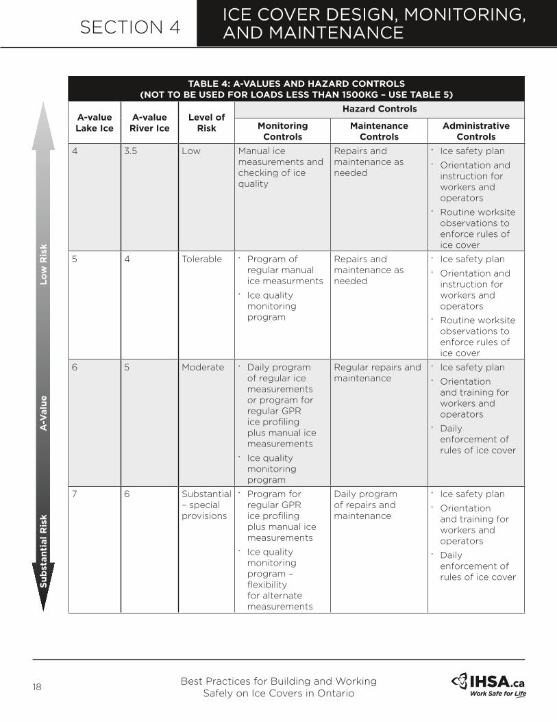
a measured ice thickness for various A-values that are in common use together with an interpreted level of risk. Table 4 describes the hazard control procedures to be used for the A-values and interpreted level of risk.
For example, if your task is to move a 15,000-kg load across an ice cover, you may choose A-values of 3.5, 4, 5, or 6. If you need to get the load across the ice and have a very short schedule and operating window, then you could select an A-value of 6 because it requires a minimum ice thickness (h) of 50 cm. However, this is a substantial risk that would require you to implement the hazard controls identified for substantial risk in Table 4. For a more conservative approach, you may select a low risk A-value of 3.5, where the minimum ice thickness (h) is 70 cm. This A-value requires the hazard controls identified for low risk in Table 4.
In between these two A-values are two other choices: A of 4 and A of 5. An A-value of 4 is tolerable risk and the minimum ice thickness for 15,000 kg is 65 cm. An A-value of 5 is moderate risk and the minimum ice thickness for 15,000 kg is 55 cm. Both require you to implement the corresponding hazard controls in Table 4 for tolerable and moderate risk.
seCTIon 4 – ICe CoVeR DesIGn, monIToRInG, anD maInTenanCe

Best Practices for Building and Working Safely on Ice Covers in Ontario
17
SECTION 4ICE COVER DESIGN, MONITORING, AND MAINTENANCE
Gold’s Formula has been used extensively since 1971 and forms the basis for all infallible measure of the carrying capacity of an ice cover and must be combined with ice monitoring, maintenance, and administrative hazard controls.
The required ice thickness for a given vehicle load must be determined in conjunction with the hazard control process outlined in Section 3. An appropriate A-value is chosen based on balancing risk level against operational controls. Those
controls are usually linked to project requirements. For example, if the project requires heavy vehicle traffic and a high traffic volume, then it may not be feasible to design and build an ice cover based on a conservative (low) A-value. However, the risk posed by choosing a higher A-value can be balanced by implementing hazard controls to reduce the risk of the breakthrough hazard. Table 4 shows how A-values are used with appropriate controls to maintain the safety of the ice cover.
Table 3: allowable loaDs In kGs foR a-ValUes anD effeCTIVe ICe THICkness
h=effective Ice Thickness (cm)
a=3.5 a=4 a=5 a=6
low Risk (kg) Tolerable Risk (kg) moderate Risk (kg) substantial Risk (kg)
20 1,400 * * *
25 2,200 * * *
30 3,150 * * *
35 4,300 4,900 6,120 7,350
40 5,600 6,400 8,000 9,600
45 7,100 8,100 10,100 12,100
50 8,750 10,000 12,500 15,000
55 10,600 12,100 15,100 18,100
60 12,600 14,400 18,000 21,600
65 14,800 16,900 21,100 25,300
70 17,100 19,600 24,500 29,400
75 19,700 22,500 28,100 33,700
80 22,400 25,600 32,000 38,400
85 25,300 28,900 36,100 43,300
90 28,300 32,400 40,500 48,600
95 31,600 36,100 45,100 54,100
100 35,000 40,000 50,000 60,000
105 38,600 44,100 55,100 63,500
110 42,300 48,400 60,500 **
115 46,300 52,900 63,500 **
120 50,400 57,600 ** **
125 54,700 62,500 ** **
127 56,450 63,500 ** **
Limitations: This table must be used in conjunction with the hazard controls identified in Table 4.
low Risk allowable load (P=kg) substantial Risk
*Refer to Table 5. **Seek the advice of a professional engineer.
Best Practices for Building and Working Safely on Ice Covers in Ontario
18
SECTION 4
Table 4: a-ValUes anD HaZaRD ConTRols (noT To be UseD foR loaDs less THan 1500kG – Use Table 5)
a-value lake Ice
a-value River Ice
level of Risk
Hazard Controls
monitoring Controls
maintenance Controls
administrative Controls
4 3.5 Low Manual ice measurements and checking of ice quality
Repairs and maintenance as needed
•
• Ice safety plan• Orientation and
instruction for workers and operators
• Routine worksite observations to enforce rules of ice cover
5 4 Tolerable • Program of regular manual ice measurments
• Ice quality monitoring program
Repairs and maintenance as needed
• Ice safety plan• Orientation and
instruction for workers and operators
• Routine worksite observations to enforce rules of ice cover
6 5 Moderate • Daily program of regular ice measurements or program for regular GPR ice profiling plus manual ice measurements
• Ice quality monitoring program
Regular repairs and maintenance
• Ice safety plan• Orientation
and training for workers and operators
• Daily enforcement of rules of ice cover
7 6 Substantial – special provisions
• Program for regular GPR ice profiling plus manual ice measurements
• Ice quality monitoring program – flexibility for alternate measurements
Daily program of repairs and maintenance
• Ice safety plan• Orientation
and training for workers and operators
• Daily enforcement of rules of ice cover
su
bst
an
tial
Ris
k
a-V
alu
e
lo
w R
isk
ICE COVER DESIGN, MONITORING, AND MAINTENANCE
Best Practices for Building and Working Safely on Ice Covers in Ontario
19
SECTION 4ICE COVER DESIGN, MONITORING, AND MAINTENANCE
4.1.2 effective Ice ThicknessEffective ice thickness (h) as established in Table 3 is defined as the good quality, well-bonded clear and blue ice that is measured in an ice cover. White ice is considered to have 1⁄2 the strength of blue ice. Effective ice thickness is 100% blue ice + 50% white ice for a well-bonded layer (refer to the Treasury Board document for further information). Poor quality or poorly bonded ice should not be included in the measurement of ice thickness. The following are examples of ice that should be excluded from the measurements if they are encountered:
•
• Ice layer with water lens (>5 mm diameter) with a cumulative volume greater than 10% of the total volume.
•
• Ice layer with visible, incompletely frozen frazil (slush) ice.
•
• Ice layer that is poorly bonded to the adjoining layer.
•
• Ice layer that has been found to have a strength less than 50% of good quality blue ice (a number of specialized methods are available for determining ice strength).
•
• Ice that has wet cracks.
The number and coverage of the ice thickness measurements can also factor into the calculation of the allowable loads—more measurements increase the confidence of ice measurements, as does taking the measurements over a wide area. Follow the procedure described in Ice Monitoring Controls (Section 4.2) to determine the minimum ice thickness. Table 3 and Figure 19 show the calculated loads for A-values. Table 4 describes the hazard controls to be used with the A-value and interpreted level of risk.
4.1.3 Recommended short-Term working loads on Ice CoversIt is important to determine the weight of the equipment or vehicles before they are placed on the ice cover. Although equipment/vehicle manuals often provide weights, these often do not include the weight of fuel, extra equipment, or personnel. When in doubt, equipment or vehicles should be weighed to determine actual weight.
A professional engineer should provide recommendations for loads greater than 63,500 kg.
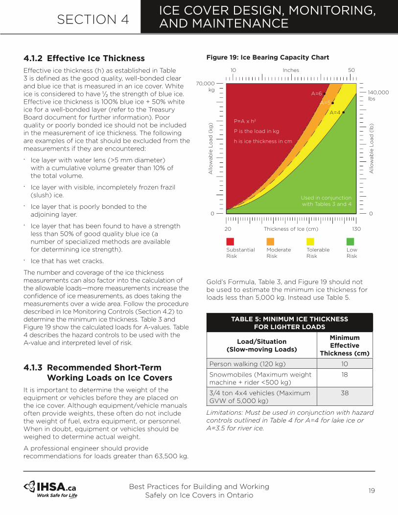
figure 19: Ice bearing Capacity Chart
Gold’s Formula, Table 3, and Figure 19 should not be used to estimate the minimum ice thickness for loads less than 5,000 kg. Instead use Table 5.
Table 5: mInImUm ICe THICkness foR lIGHTeR loaDs
load/situation (slow-moving loads)
minimum effective
Thickness (cm)
Person walking (120 kg) 10
Snowmobiles (Maximum weight machine + rider <500 kg)
18
3/4 ton 4x4 vehicles (Maximum GVW of 5,000 kg)
38
Limitations: Must be used in conjunction with hazard controls outlined in Table 4 for A=4 for lake ice or A=3.5 for river ice.
10 Inches 50
Thickness of Ice (cm)20
0 0
70,000 kg 140,000
lbsA=6
Substantial Risk
Moderate Risk
Tolerable Risk
Low Risk
A=5
A=4
P=A x h2
P is the load in kg
h is ice thickness in cm
Used in conjunction with Tables 3 and 4
Allo
wab
le L
oad
(kg
)
Allo
wab
le L
oad
(lb
)
130
Best Practices for Building and Working Safely on Ice Covers in Ontario
20
SECTION 4
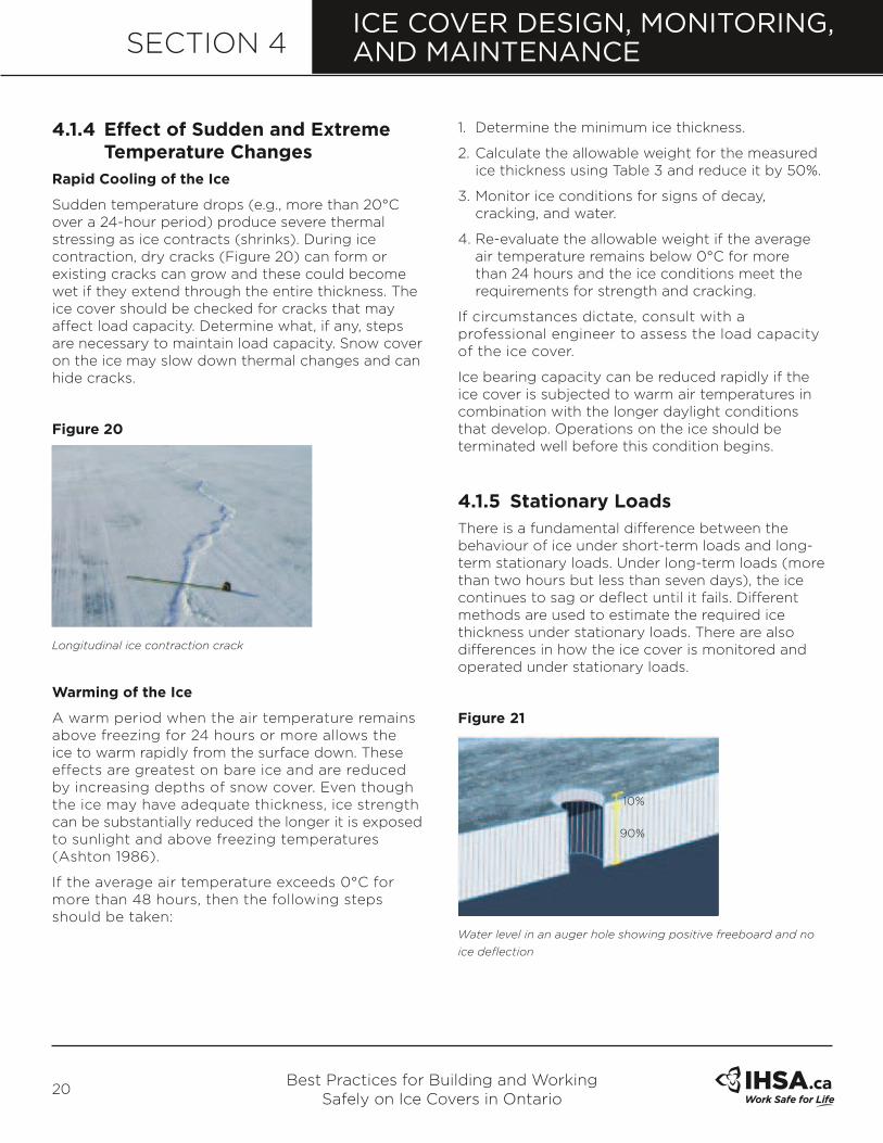
4.1.4 effect of sudden and extreme Temperature ChangesRapid Cooling of the Ice
Sudden temperature drops (e.g., more than 20°C over a 24-hour period) produce severe thermal stressing as ice contracts (shrinks). During ice contraction, dry cracks (Figure 20) can form or existing cracks can grow and these could become wet if they extend through the entire thickness. The ice cover should be checked for cracks that may affect load capacity. Determine what, if any, steps are necessary to maintain load capacity. Snow cover on the ice may slow down thermal changes and can hide cracks.
figure 20
Longitudinal ice contraction crack
warming of the Ice
A warm period when the air temperature remains above freezing for 24 hours or more allows the ice to warm rapidly from the surface down. These effects are greatest on bare ice and are reduced by increasing depths of snow cover. Even though the ice may have adequate thickness, ice strength can be substantially reduced the longer it is exposed to sunlight and above freezing temperatures (Ashton 1986).
If the average air temperature exceeds 0°C for more than 48 hours, then the following steps should be taken:
1. Determine the minimum ice thickness.
2. Calculate the allowable weight for the measured ice thickness using Table 3 and reduce it by 50%.
3. Monitor ice conditions for signs of decay, cracking, and water.
4. Re-evaluate the allowable weight if the average air temperature remains below 0°C for more than 24 hours and the ice conditions meet the requirements for strength and cracking.
If circumstances dictate, consult with a professional engineer to assess the load capacity of the ice cover.
Ice bearing capacity can be reduced rapidly if the ice cover is subjected to warm air temperatures in combination with the longer daylight conditions that develop. Operations on the ice should be terminated well before this condition begins.
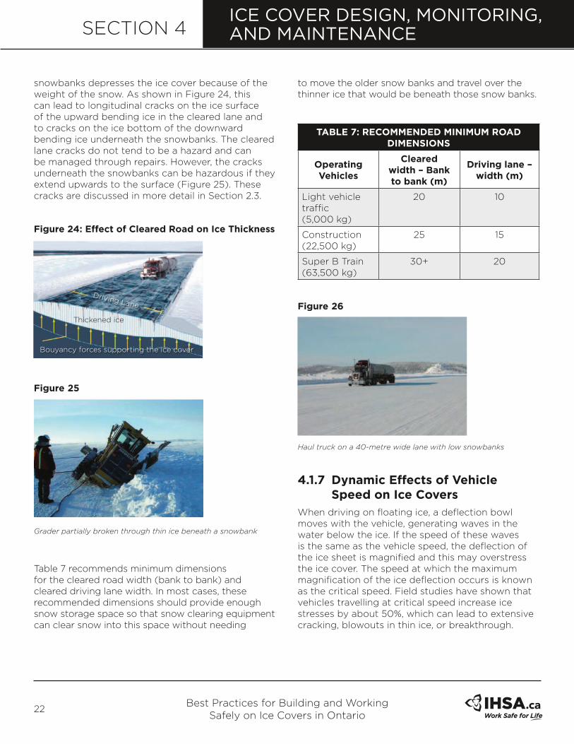
4.1.5 stationary loads
There is a fundamental difference between the behaviour of ice under short-term loads and long-term stationary loads. Under long-term loads (more than two hours but less than seven days), the ice continues to sag or deflect until it fails. Different methods are used to estimate the required ice thickness under stationary loads. There are also differences in how the ice cover is monitored and operated under stationary loads.
figure 21
Water level in an auger hole showing positive freeboard and no
ice deflection
ICE COVER DESIGN, MONITORING, AND MAINTENANCE
10%
90%

Best Practices for Building and Working Safely on Ice Covers in Ontario
21
SECTION 4
figure 22
Water level in an auger hole showing no freeboard and water is
collecting on the ice because the ice has deflected under the load.
The safety risk in placing stationary loads that are heavier than 5,000 kg onto ice should be analyzed by a professional engineer. Table 6 provides recommended minimum ice thicknesses for vehicles weighing up to 5,000 kg. Under these conditions, ice deflection should be acceptable. Ice deflection can be checked by drilling a hole through the ice and measuring the freeboard. Freeboard is the distance measured from the ice surface to the stationary water level in the hole below the surface, and it arises because ice is less dense than water so it floats. If freeboard is less than 10% the ice thickness (Figure 21), then the ice is deflecting and should be monitored while the load remains on the ice. Loads should be removed before freeboard reaches zero (Figure 22), to prevent water flooding the ice surface through an opening in the ice cover.
figure 23
Stationary load (bulk sampling drilling rig) on constructed lake ice about two metres thick
Figure 23 shows a 200 metric ton bulk sampling drill rig operating on floating lake ice that was 2 metres thick. An extensive ice monitoring program was in
place during the 14 days of drilling operations to determine if the ice deflection and ice quality were consistent with performance requirements.
Table 6: mInImUm ICe THICkness foR sTaTIonaRy/PaRkeD loaDs UP To 5,000 kG (foR moRe THan Two HoURs
bUT less THan seVen Days)
load/situationminimum effective
Thickness (cm)
Person standing 15
Snowmobiles (Maximum weight machine + rider <500 kg)
25
Loaded vehicle >500 kg but <1,000 kg
32
Loaded vehicle >1,000 but <2,000 kg
41
Vehicle >2,000 but <3,000 kg 46
3/4 ton 4x4 vehicle (Maximum GVW of 5,000 kg)
55
Limitations: Must be used in conjunction with hazard controls for a low level of risk as identified in Table 4.
If a vehicle or equipment becomes disabled on ice that does not meet the requirements of Table 6, the occupants must be prepared with the necessary emergency kits and supplies, and be ready to abandon the vehicle within two hours. The occupants should have a communications device so help can be dispatched in the event of an emergency. Workers must be evacuated immediately and arrangements made to move vehicles offshore in accordance with the emergency plan.
4.1.6 lane DimensionsIt is widely known that removing snow from the ice surface leads to thicker ice compared to areas that remain covered in insulating snow. Consequently, the snow that is on the ice must be removed or tamped down and snowbanks must be built along the sides of the road to build a cleared lane width.
However, there are two consequences when removing snow and building snowbanks: (1) the thicker ice in the cleared lane rises because it is more buoyant and (2) the thinner ice under the
ICE COVER DESIGN, MONITORING, AND MAINTENANCE
100%
Best Practices for Building and Working Safely on Ice Covers in Ontario
22
SECTION 4
snowbanks depresses the ice cover because of the weight of the snow. As shown in Figure 24, this can lead to longitudinal cracks on the ice surface of the upward bending ice in the cleared lane and to cracks on the ice bottom of the downward bending ice underneath the snowbanks. The cleared lane cracks do not tend to be a hazard and can be managed through repairs. However, the cracks underneath the snowbanks can be hazardous if they extend upwards to the surface (Figure 25). These cracks are discussed in more detail in Section 2.3.
figure 24: effect of Cleared Road on Ice Thickness
figure 25
Grader partially broken through thin ice beneath a snowbank
Table 7 recommends minimum dimensions for the cleared road width (bank to bank) and cleared driving lane width. In most cases, these recommended dimensions should provide enough snow storage space so that snow clearing equipment can clear snow into this space without needing
to move the older snow banks and travel over the thinner ice that would be beneath those snow banks.
Table 7: ReCommenDeD mInImUm RoaD DImensIons
operating Vehicles
Cleared width – bank to bank (m)
Driving lane – width (m)
Light vehicle traffic(5,000 kg)
20 10
Construction (22,500 kg)
25 15
Super B Train (63,500 kg)
30+ 20
figure 26
Haul truck on a 40-metre wide lane with low snowbanks
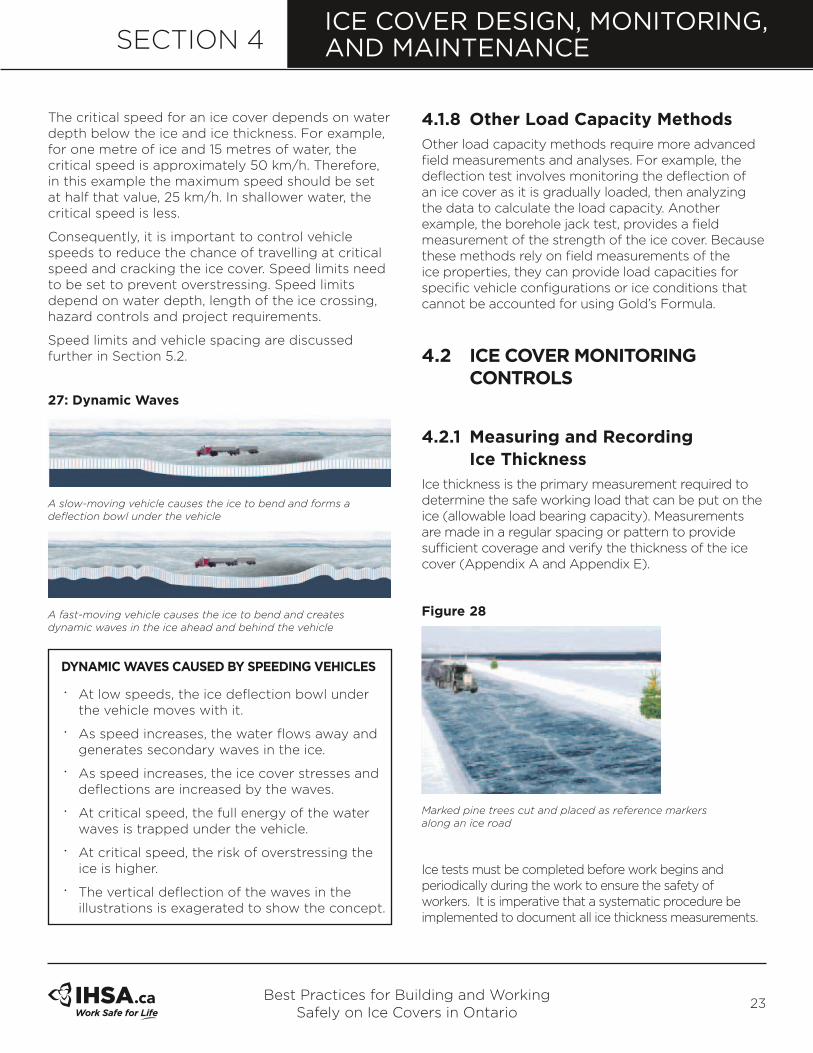
4.1.7 Dynamic effects of Vehicle speed on Ice CoversWhen driving on floating ice, a deflection bowl moves with the vehicle, generating waves in the water below the ice. If the speed of these waves is the same as the vehicle speed, the deflection of the ice sheet is magnified and this may overstress the ice cover. The speed at which the maximum magnification of the ice deflection occurs is known as the critical speed. Field studies have shown that vehicles travelling at critical speed increase ice stresses by about 50%, which can lead to extensive cracking, blowouts in thin ice, or breakthrough.
ICE COVER DESIGN, MONITORING, AND MAINTENANCE
Thickened ice
Driving Lane
Bouyancy forces supporting the ice cover
Best Practices for Building and Working Safely on Ice Covers in Ontario
23
SECTION 4
The critical speed for an ice cover depends on water depth below the ice and ice thickness. For example, for one metre of ice and 15 metres of water, the critical speed is approximately 50 km/h. Therefore, in this example the maximum speed should be set at half that value, 25 km/h. In shallower water, the critical speed is less.
Consequently, it is important to control vehicle speeds to reduce the chance of travelling at critical speed and cracking the ice cover. Speed limits need to be set to prevent overstressing. Speed limits depend on water depth, length of the ice crossing, hazard controls and project requirements.
Speed limits and vehicle spacing are discussed further in Section 5.2.
27: Dynamic waves
A slow-moving vehicle causes the ice to bend and forms a deflection bowl under the vehicle
A fast-moving vehicle causes the ice to bend and creates dynamic waves in the ice ahead and behind the vehicle
DynamIC waVes CaUseD by sPeeDInG VeHICles
•
• At low speeds, the ice deflection bowl under the vehicle moves with it.
•
• As speed increases, the water flows away and generates secondary waves in the ice.
•
• As speed increases, the ice cover stresses and deflections are increased by the waves.
•
• At critical speed, the full energy of the water waves is trapped under the vehicle.
•
• At critical speed, the risk of overstressing the ice is higher.
•
• The vertical deflection of the waves in the illustrations is exagerated to show the concept.
4.1.8 other load Capacity methodsOther load capacity methods require more advanced field measurements and analyses. For example, the deflection test involves monitoring the deflection of an ice cover as it is gradually loaded, then analyzing the data to calculate the load capacity. Another example, the borehole jack test, provides a field measurement of the strength of the ice cover. Because these methods rely on field measurements of the ice properties, they can provide load capacities for specific vehicle configurations or ice conditions that cannot be accounted for using Gold’s Formula.
4.2 ICe CoVeR monIToRInG ConTRols
4.2.1 measuring and Recording Ice ThicknessIce thickness is the primary measurement required to determine the safe working load that can be put on the ice (allowable load bearing capacity). Measurements are made in a regular spacing or pattern to provide sufficient coverage and verify the thickness of the ice cover (Appendix A and Appendix E).
figure 28
Marked pine trees cut and placed as reference markers along an ice road
Ice tests must be completed before work begins and periodically during the work to ensure the safety of workers. It is imperative that a systematic procedure be implemented to document all ice thickness measurements.
ICE COVER DESIGN, MONITORING, AND MAINTENANCE

Best Practices for Building and Working Safely on Ice Covers in Ontario
24
SECTION 4ICE COVER DESIGN, MONITORING, AND MAINTENANCE
Measurement locations should be taken either with a Global Positioning System (GPS) receiver or marked with stakes, or another reliable system (Figure 28) so that these locations can be tracked in future measurements or identified for repairs. This information is a key element in the ice safety plan. These measurements are vital to investigating any ice cover failures that may occur.
figure 29
An auger being used to drill a hole through the ice cover
Manual measurements are made by cutting a hole in the ice cover with an auger, a saw, or an ice chisel and then directly measuring the ice thickness (Figure 29).
Over the past 20 years, Ground Penetrating Radar (GPR) ice profiling has become a more common method, providing a continuous, non-destructive measurement of ice thickness over large areas or distances. GPR profiling can be combined with GPS to retrieve the data (Figure 30). GPR ice profiling should be carried out by trained personnel and the results reviewed by qualified professionals.
figure 30
Dual channel GPR ice profiling equipment (being pulled behind a snowmobile) measuring ice thickness and water depth in a single pass
Pre-Construction Ice Thickness measurements
An ice cover hazard assessment must be conducted and reviewed by field personnel before starting any ice thickness measurement. Suitable equipment and personal protective equipment must be provided and used as prescribed.
Initial testing should be conducted by at least two trained crew members travelling separately over the ice. The work could be carried out by travelling:
•
• on foot
•
• by snowmobile
•
• by amphibious vehicle.
The safe ice thickness limits for fully loaded vehicles must be known and followed at all times. During pre-construction ice measurements, calculate the minimum ice thickness required for fully loaded vehicles being used during pre-construction, using a conservative value of A=4 in Gold’s Formula for initial use of the ice cover. Ice thickness can be measured using either the manual method (see Appendix A) or GPR method (see Appendix B).
Amphibious vehicles such as the Swedish Hagglund have been used to transport personnel on the ice during initial measurements. Light snow machines can be used (in pairs) as long as the ice is checked ahead of them to verify that it is thick enough for safe operation.
Procedures for measuring ice thickness before construction should also include the following:
•
• Testing should be representative of snow-covered and non-snow-covered areas.
•
• While testing, the crew should also be checking the ice for cracks and noting the snow load.
•
• If vehicles are used, two separate vehicles must be used at all times and must be separated at a safe distance unless ice conditions are known.
•
• Wheeled vehicles should be equipped with a winch.
•
• All vehicles must have two-way radios and/or satellite phones, as well as survival supplies.
•
• An agreed-upon call-in procedure must be followed with a safety contact in the base office.
•
• High-visibility (orange or red) survival flotation suits and other required PPE must be worn at all times (preferable to Personal Flotation Devices/PFDs).

Best Practices for Building and Working Safely on Ice Covers in Ontario
25
SECTION 4ICE COVER DESIGN, MONITORING, AND MAINTENANCE
•
• The route should be recorded on a map or with GPS coordinates; if others will follow the tested route, it should be marked so it is easily identified. Use items such as high-visibility stakes or pylons, or flagging tape.
•
• Outfit all vehicles with appropriate safety equipment (Appendix C) and fuel for a full day’s work.
•
• Follow safe operating speed guidelines (refer to Table 8 on page 30).
•
• A standard operating procedure should be prepared to document these requirements.
Some projects, such as hydrotechnical measurements or water sampling, involve working on foot on thin, floating ice. A hazard assessment must be undertaken, and special training, PPE, and safety protocols are required for such work. For example, working on river ice near open water requires water and ice safety training, PPE, and an emergency plan that takes into account the higher risk of breakthrough and immersion.
During Construction – Ice Profiling
Periodic ice thickness measurements should be conducted as the ice grows, to monitor its progress and approve the use of heavier vehicles. Ice thickness measurements can be carried out using either manual or GPR methods. The choice of a profiling vehicle depends on the minimum ice thickness required for the given vehicle weight.
In addition to procedures listed for pre-construction, consider the following when carrying out ice profiling:
•
• Calculate the required ice thickness limits for fully loaded vehicles (maximum of 22,500 kg) using A=4 in Gold’s Formula for initial use of the road,
For more information on ice measurements and ice profiling, see Appendix A—in particular, Table A-1: Recommended Maximum Spacing of Auger Test Holes, Table A-2: Recommended Minimum Frequency Of Auger Test Holes, and Table A-3: Ice Cover Profile Template. Also, see Appendix B: Guide for GPR Ice Profiling and Table F-1: Ice Cover Inspection Template.
when ice is measured by manual methods as described in Appendix A.
•
• Calculate the required ice thickness limits for fully loaded vehicles (maximum weight of 22,500 kg) using A=5 in Gold’s Formula for initial use of the road, when ice is measured by GPR method as described in Appendix B.
•
• Follow safe operating speed guidelines (refer to Table 8 on page 30).
•
• Mark approved or tested lanes.
•
• Communicate with other personnel who have tested, travelled, or worked on the ice (check prior to starting work).
•
• Establish a procedure to ensure the field crew calls in to the safety contact.
•
• Outfit all vehicles with appropriate safety equipment (Appendix C) and fuel for a full day’s work.
•
• Document these steps by preparing a standard operating procedure.
During operation – Ice Profiling
Ice profiling should continue for quality assurance purposes after the ice cover is opened to traffic or for other purposes. The ice cover would normally be open to vehicles used for patrol and reconnaissance such as heavy-duty pickup trucks. Ice covers used as work platforms and used recreationally may be serviced by snow-clearing and ice-flooding vehicles. The purpose of operational ice profiling is to confirm operational load limits over time and to allow those limits to safely increase with ice growth.
See Table F-1 in Appendix F for a sample ice cover inspection template.

Best Practices for Building and Working Safely on Ice Covers in Ontario
26
SECTION 4
4.2.2 monitoring Ice CracksSurface cracks should be checked by noting their appearance, determining if they are wet or dry, and assessing their width and depth. The process for assessing ice cracks is shown in the flow chart below.
figure 31: assessing Ice Cracks
ICE COVER DESIGN, MONITORING, AND MAINTENANCE
AssessingIce Cracks
Is crack wet or dry?
Close areato loads
Bridge crack with rig mator an engineered mat
Wet Dry
How deepis crack compared to
ice thickness?
>50% of icethickness
25 to 50% ofice thickness
<25% of icethickness
Close area andrepair crack
Close area insections andrepair crack
Monitor andrepair as required
Loads travelperpendicular
to crack
Close area and divertloads elsewhere
Close area and repaircrack before re-opening
Reduce allowable loadby 50% and monitor

Best Practices for Building and Working Safely on Ice Covers in Ontario
27
SECTION 4
The water in wet cracks indicates that the cracks reach the bottom of the ice cover. Wet cracks that extend over the ice cover for several metres reduce the bearing capacity of ice. Theoretical studies show that the presence of one wet crack reduces the bearing capacity of the ice by 50% (Ashton 1986). Areas with wet cracks should be flagged off and workers kept away from them. These areas should also be repaired, bridged, or closed off completely to people and equipment/vehicles.
Dry cracks show that they do not penetrate the ice sheet and are not an immediate problem. Dry cracks that extend more than 50% of the ice thickness should be repaired immediately or avoided. Dry cracks may be hard to detect when covered by snow, and this is another reason to keep the ice cover clear of snow.
The following are recommended modifications to ice loads given the nature of the crack.
•
• Single dry crack (>2.5 cm thick): reduce load by one third or to 66% of allowable
•
• Intersecting dry cracks (>2.5 cm thick): reduce load by two-thirds or to 33% of allowable
•
• Single wet crack: reduce by one-half or to 50% of allowable
•
• Two wet cracks meet at right angles: reduce to one-quarter or to 25% of allowable
See Table F-1 for a sample ice cover inspection template.
4.3 maInTenanCe ConTRolsRepairs and maintenance should be undertaken to address cracks, thin zones, or other damaged areas that may compromise the load-bearing capacity of the ice cover. Snow clearing may also be required to keep the surface clear and to promote natural ice growth. Some ice conditions may require temporary closure of the ice cover to equipment or vehicles, as discussed in Section 5.3.
All cracks that extend more than 50% of the ice thickness should be repaired or traffic diverted around them. Major cracks that have been repaired should be checked once they have re-frozen. Rig mats can be used to bridge cracks that will not heal (re-freeze) or that have a change in elevation that prevents vehicles from crossing. Detours may need to be built around severely cracked areas.
figure 32
Flooding crew repairing an ice road
ICE COVER DESIGN, MONITORING, AND MAINTENANCE

Best Practices for Building and Working Safely on Ice Covers in Ontario
28
DEVELOPING YOUR ICE SAFETY PLANSECTION 5
5.1 ICe safeTy PlanWhen working on ice covers, there is always a risk of ice failure and breakthrough that can have potentially fatal consequences. Employers and constructors must conduct a hazard assessment. An Ice Safety Plan is essential to ensuring the health and safety of workers.
The following sections and the appendices provide information to control ice cover hazards based on a project’s specific needs: Section 3 – Ice Cover Hazard Controls; Section 4.1 – Design Controls; Section 4.2 – Ice Cover Monitoring Controls; Section 5 – Developing Your Ice Safety Plan; and Section 5.4 – Emergency Response Planning.
The Ice Safety Plan should be written and the employer must effectively communicate it to all supervisors and their workers who are affected or potentially may be affected by the ice cover hazards. The flow chart (Figure 33) provides guidance on how to develop an Ice Safety Plan and effectively communicate it to workers and supervisors.
5.2 sTanDaRD oPeRaTInG PRoCeDURes foR ICe CoVeRsStandard operating procedures are an effective means of controlling hazards through administrative controls and are related to the actual operation of the ice cover. The most important operating procedures pertaining to ice covers are discussed below.
5.2.1 approved Use of Ice CoversTraffic should be restricted to vehicles with a gross vehicle weight (GVW) that meets the requirements for bearing capacity of the current ice conditions. Furthermore, traffic should be restricted to ice covers that have been monitored and ice conditions that have been assessed, documented and approved by the owner (or their designate).
figure 33: Ice safety Plan
Identify existing or potential hazards and determine how to eliminate or control them.
•
• Start before work begins at the ice cover.
•
• Involve the affected workers.
•
• Follow the flow chart in Section 3: Ice Cover Hazard Controls.
•
• Develop an Ice Cover Emergency Response Plan as indicated in Section 5.4: Emergency Response Planning.
Develop an Ice safety Plan that incorporates
•
• Hazard elimination
•
• Hazard controls
•
• An Emergency Response Plan.
Inform and instruct all workers and supervisors about the Ice safety Plan and safe work procedures.
•
• Confirm their understanding.
•
• Discuss the Ice Safety Plan before work begins and when there are changes to the plan.
•
• Communicate details of the Ice Safety Plan at new worker orientations, daily pre-job talks, and work group and safety meetings.
•
• Make written copies of the Ice Safety Plan readily available to all.
Periodically review the hazard controls in the Ice safety Plan and update it as needed.
•
• Review at reasonable intervals to prevent the development of any unsafe working conditions or when there are changes in work.
•
• Review when there is a sudden, significant change in weather.
•
• Inform workers and supervisors of changes
seCTIon 5 – DeVeloPInG yoUR ICe safeTy Plan

Best Practices for Building and Working Safely on Ice Covers in Ontario
29
SECTION 5 DEVELOPING YOUR ICE SAFETY PLAN
Approved traffic areas should be identified with markers such as barricades, pylons, and signage (Figure 34).
figure 34
Barricade markers
5.2.2 Verifying Vehicle and equipment weightsThe gross vehicle weight and the minimum ice thickness should be determined before deploying any vehicle or equipment on the ice cover. If necessary, the vehicle or equipment should be weighed with all of the components, fuel, tools, and gear that will be included with it. This information should be affixed to the vehicle or equipment where the operator can read it to make sure it is safe to go on the ice.
figure 35
Portable vehicle scale
5.2.3 stationary loads on Ice CoversParked vehicles and equipment should be spaced no closer than two vehicle and equipment lengths for durations less than two hours. Parking for more than two hours on the ice cover should be prohibited unless the construction of the ice cover meets the requirements in Section 4.1.5. Otherwise, arrangements should be made to move disabled vehicles off the ice cover as soon as possible.
5.2.4 minimum Distances between Vehicles and equipmentFor light vehicles (up to 5,000 kg), the distance between vehicles should be at least 200 times the thickness of the ice. For heavier vehicles (greater than 5,000 kg and up to 63,500 kg), the distance should be increased to 500 times the ice thickness. If the water body is smaller than these limits, then only one vehicle or piece of equipment should be permitted on the ice cover at a time (Figure 36). A loaded vehicle should never overtake and pass a moving loaded vehicle going in the same direction.
figure 36
Sign that limits travel on the ice bridge to one vehicle at a time
5.2.5 maximum speed when Travelling on Ice CoverThe maximum speed for loaded vehicles travelling across ice covers is 25 km/h for ideal ice and driving conditions. The speed limit when approaching shorelines is 10 km/h. Speed limits should be adjusted to local conditions by considering weather

Best Practices for Building and Working Safely on Ice Covers in Ontario
30
DEVELOPING YOUR ICE SAFETY PLANSECTION 5
conditions, ice quality, vehicle loads, proximity of vehicles, and the hazard controls in place. Speed limits must be posted and may be lowered depending on ice conditions and vehicle loads.
The observations showed that vehicle speed was a factor for some of the failures. Particular caution must be exercised when approaching shore, or travelling close to it, because of more severe stressing of the cover due to reflections of the hydrodynamic wave. Vehicle speeds should always be strictly controlled when operating on ice. Gold (1971)
Table 8: sUGGesTeD maXImUm sPeeD lImITs
Vehicle/Ice Conditions
suggested maximum
speed limit (km/h)*
Vehicle profiling during construction
10
Vehicle approaching shore line 10
Vehicle passing flood crews 10
Load vehicles travelling in opposite directions
10
Meeting oncoming vehicles 10
Vehicle operating at the minimum ice thickness for its weight
25
Vehicle operating at ice conditions that are two times the minimumice thickness for its weight
35
* Speed limits higher than these should be approved by a professional engineer. Heavily loaded vehicles should never pass each other.
5.3 ICe CoVeR ClosUReIt may be necessary to temporarily close ice covers due to inclement weather, poor surface conditions, or poor ice conditions. Inclement weather (such as blizzards, whiteouts, or fog) poses risks associated with poor visibility when travelling. Poor surface conditions due to snow drifting and natural water overflow areas also pose risks to users. Poor ice conditions associated with changes in water level,
erosion of ice, extensive cracking, or excessive wear due to use can increase the risk of breakthrough. Owners should suspend ice cover operations until these hazards can be eliminated or controlled.
Normally, ice covers are closed before spring thaw begins and the ice cover begins to decay. Decay of ice covers is affected mainly by solar radiation and by the reflecting properties of the ice surface. For example, ice decays more rapidly when its surface is bare and/or exposed to long hours of sunshine. Ice growth stops and ice decay starts before air temperatures rise above the melting point of the ice. Ice temperature and ice quality should be monitored regularly—especially during spring thaw—to determine if the ice cover has adequate bearing capacity to support ice operations.
Suspended areas should be adequately identified with proper signage, hazard markings, and delineation (Figure 37).
figure 37
Road closure sign
5.4 emeRGenCy ResPonse PlannInGAll construction projects must have a written emergency procedure that complies with section 17 of Ontario Regulation 213/91 – Construction Projects. The plan should include the following:
•
• Identification of potential emergencies
•
• Procedures for dealing with the emergencies
•
• Procedures for rescue and evacuation
•
• Identification of emergency responders and evacuation workers

Best Practices for Building and Working Safely on Ice Covers in Ontario
31
DEVELOPING YOUR ICE SAFETY PLANSECTION 5
•
• Identification, location and operational procedures for emergency equipment and PPE for rescue and evacuation workers
•
• Emergency communication requirements (i.e., telephones, two-way radios, or other systems)
•
• First aid equipment and personnel that comply with the Regulation 1101, First Aid Requirements
•
• Emergency response training requirements
The Emergency Response Plan must be reviewed by the constructor and Joint Health and Safety Committee (JHSC) (if any) and posted in a conspicuous location. The plan should be reviewed, tested and updated on a regular basis.
Once the ice cover is operational, an appropriate emergency plan should also be put in place.
figure 38
Emergency rescue drill
5.5 emeRGenCy PRoCeDUResAppendix D outlines generic emergency procedures to use in the event of an incident that affects the health and safety of workers. Site-specific procedures should be developed and would override these recommendations.
• After the scene of an on-ice incident is deemed safe, rescue the victim and ensure that he or she receives the best available first aid treatment on site.
• Prepare the victim for transport.
• Determine the appropriate method of transport given the severity of the injury and access to the worksite.
• Once the victim is transported, cordon off the area and post a sign or beacon at the site to warn others of the potential hazard.

Best Practices for Building and Working Safely on Ice Covers in Ontario
32
SECTION 6 PERSONAL PROTECTIVE EQUIPMENT
Ice Safety Plans must address the requirements related to personal protective equipment (PPE) as follows:
1. Clearly identify the PPE required (e.g., ice picks).
2. Provide training on the selection, care, use, and limitations of PPE.
3. Monitor the condition and use of PPE and actions to take if defects/deficiencies are noted.
A life jacket or personal flotation device, such as a survival flotation suit, must be worn if a worker is exposed to the risk of drowning, for example, during the pre-construction and construction phases of preparing a floating ice cover.
Flotation devices must also be worn by workers working in situations where the thickness and quality of the ice cover is unknown or questionable, for example, when workers are taking water samples at the edge of open water on a flowing river. The type of flotation device needed will vary based on the conditions of use and the features required in order to perform work safely. Survival flotation suits, for example, help prevent hypothermia by providing a barrier against cold water. They also offer buoyancy, much like a life jacket. Both of these features may extend the survival time of a person who has fallen into frigid water.
seCTIon 6 – PeRsonal PRoTeCTIVe eQUIPmenT

Best Practices for Building and Working Safely on Ice Covers in Ontario
33
SECTION 7 REFERENCES
7.1 GoVeRnmenT RefeRenCes•
• Government of Alberta 2013. Best Practice for Building and Working Safely on Ice Covers in Alberta.
•
• Treasury Board of Canada. Safety Guide for Operations over Ice.
•
• Commission de la santé et de la securité du travail du Quebec 1996. Travaux sur les champs de glace. Bibliothèque nationale du Quebec.
•
• Department of Transportation 2007. A Field Guide to Ice Construction Safety. Government of the Northwest Territories.
•
• Manitoba Transportation and Government Services 2005. Inspector’s Manual for the Construction and Maintenance of Winter Roads, 7th edition.
•
• Safe Operating Procedures for Winter Roads Committee 2007. Winter Roads Handbook. Saskatchewan Ministry of Highways and Infrastructure.
•
• Winter Road Safety Committee 2005. Contractor’s Manual for the Construction and Maintenance of Winter Roads, 5th edition. Manitoba Transportation and Government Services.
7.2 TeCHnICal RefeRenCesAshton, G.D. 1985. Deterioration of floating ice covers. ASME Journal of Energy Resources Technology, 107: 177-182.
Ashton, G.D. 1986. River and Lake Ice Engineering. Water Resources Publications, Littleton, Colorado.
Canadian Red Cross Society 2006. Drownings in Canada and Other Water-Related Injuries, 1991-2000—Module 2: Ice & Cold Water. The Canadian Red Cross Society.
Gold, L.W. 1971. The use of ice covers for transportation. Canadian Geotechnical Journal 8: 170-181.
Hayley, D.W., and Proskin, S.A. 2008. Managing the safety of ice covers used for transportation in an environment of climate warming. Presentation to the 4th Canadian Conference on Geohazards, Quebec.
Lock, G.S.H. 1990. The Growth and Decay of Ice. Cambridge University Press, Cambridge, UK.
MacFarlane, I.C. (ed.) 1969. Muskeg Engineering Handbook. University of Toronto Press.
Pounder, E.R. 1965. The Physics of Ice. Pergamon Press, Oxford.
Giesbrecht G, Hamlet M, Hubbell F. 2004. Frozen Mythbusters. Wilderness Medicine Newsletter – Principles and Practices of Extended Care and Rescue. Vol. 15, No. 6. www.lifesaving.com/files/Mythbusters_sm.pdf, accessed September 15, 2009
7.3 mIsCellaneoUs RefeRenCesInfrastructure Health and Safety Association (IHSA). www.ihsa.ca phone: 1-800- 263-5024
Workplace Safety North (WSN). www.workplacesafetynorth.ca phone: 1-888-730-7821
Ontario Ministry of Labour. www.labour.gov.on.ca phone: 1-877-202-0008
Iglauer, Edith 1975. Denison’s Ice Road. E.P. Dutton & Co, Inc., New York.
Marston, D.L. 1985. Law for Professional Engineers, 2nd Edition. McGraw-Hill Ryerson Ltd., Toronto.
Sigfusson, Svein. 1992. Sigfusson’s Roads. Watson and Dwyer Publishing Ltd., Winnipeg, Canada.
History Television. Ice Road Truckers. 2009. www.history.com/shows/ice-road-truckers/episodes/season-3
7.4 PHoTo anD IllUsTRaTIon CReDITsKevin Kelly Illustrations EBA Engineering Consultants Ltd Tibbitt to Contwoyto Winter Road Joint Venture Nuna Logistics BHP Billiton Rescue Canada University of Alberta Girard Enterprises Municipality of Wood Buffalo Shell Canada Energy ATCO Electric Alberta Employment and Immigration
seCTIon 7 – RefeRenCes
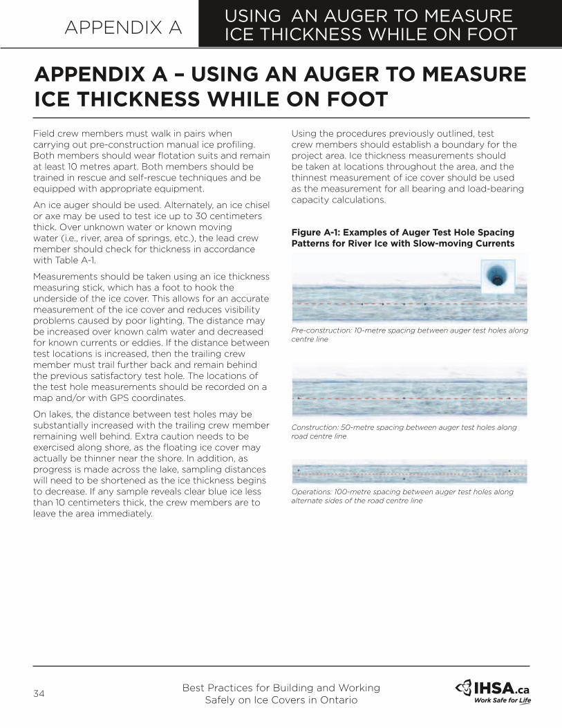
Best Practices for Building and Working Safely on Ice Covers in Ontario
34
USING AN AUGER TO MEASURE ICE THICKNESS WHILE ON FOOTAPPENDIX A
Field crew members must walk in pairs when carrying out pre-construction manual ice profiling. Both members should wear flotation suits and remain at least 10 metres apart. Both members should be trained in rescue and self-rescue techniques and be equipped with appropriate equipment.
An ice auger should be used. Alternately, an ice chisel or axe may be used to test ice up to 30 centimeters thick. Over unknown water or known moving water (i.e., river, area of springs, etc.), the lead crew member should check for thickness in accordance with Table A-1.
Measurements should be taken using an ice thickness measuring stick, which has a foot to hook the underside of the ice cover. This allows for an accurate measurement of the ice cover and reduces visibility problems caused by poor lighting. The distance may be increased over known calm water and decreased for known currents or eddies. If the distance between test locations is increased, then the trailing crew member must trail further back and remain behind the previous satisfactory test hole. The locations of the test hole measurements should be recorded on a map and/or with GPS coordinates.
On lakes, the distance between test holes may be substantially increased with the trailing crew member remaining well behind. Extra caution needs to be exercised along shore, as the floating ice cover may actually be thinner near the shore. In addition, as progress is made across the lake, sampling distances will need to be shortened as the ice thickness begins to decrease. If any sample reveals clear blue ice less than 10 centimeters thick, the crew members are to leave the area immediately.
Using the procedures previously outlined, test crew members should establish a boundary for the project area. Ice thickness measurements should be taken at locations throughout the area, and the thinnest measurement of ice cover should be used as the measurement for all bearing and load-bearing capacity calculations.
figure a-1: examples of auger Test Hole spacing Patterns for River Ice with slow-moving Currents
Pre-construction: 10-metre spacing between auger test holes along centre line
Construction: 50-metre spacing between auger test holes along road centre line
Operations: 100-metre spacing between auger test holes along alternate sides of the road centre line
aPPenDIX a – UsInG an aUGeR To measURe ICe THICkness wHIle on fooT

Best Practices for Building and Working Safely on Ice Covers in Ontario
35
APPENDIX AUSING AN AUGER TO MEASURE ICE THICKNESS WHILE ON FOOT
GUIDanCe on sPaCInG anD fReQUenCy of aUGeR TesT Holes In ICe
The number and spacing of manual auger test holes to check ice thickness depend on:
Table a-1: ReCommenDeD maXImUm sPaCInG of aUGeR TesT Holes foR measURInG ICe THICkness
water body Type Pre-construction Construction operations
Rivers – fast moving or high currents
5 m between test holes alond centre line or a minimum of 5 holes
25 m between test holes along alternating sides of centre line
50 m between test holes along alternating sides of centre line
Rivers – slow moving and within 250 m of shore
10 m between test holes along centre line
50 m between test holes along centre line
Check known thin areas.
100 m between test holes along alternating sides of centre line
Check known thin areas.
Rivers – slow moving and more than 250 m offshore
20 m between test holes along centre line
100 m between test holes along centre line
200 m between test holes along alternating sides of centre line
Lakes – within 250 m of shore
10 m between test holes along centre line
50 m between test holes along alternating sides of centre line
Check known thin areas.
100 m between test holes along alternating sides of centre line
Check known thin areas.
Lakes – more than 250 m offshore
20 m between test holes along centre line
100 m between test holes along centre line
200 m between test holes along centre line
Note: These are maximum spacings for ice auger measurements. Additional measurements may be required in thin areas.
Table a-2: ReCommenDeD mInImUm fReQUenCy of aUGeR TesT Hole measURemenTs
Pre-construction Construction operations
Check every 2-3 days to monitor ice growth until minimum ice thickness is achieved to deploy heavier pieces of equipment.
Check every 4-7 days or more frequently to monitor for specific ice requirements for construction equipment and operations.
Test entire route prior to increasing load limits.
Monitor thin areas as recommended by ice cover supervisor (e.g., every 2-4 days).
Note: More frequent measurements may be required to monitor changes in ice conditions due to environmental effects (e.g., warming, currents) or changes in loads (e.g., heavier, or more frequent loads).

Best Practices for Building and Working Safely on Ice Covers in Ontario
36
APPENDIX A
Table a-3: ICe CoVeR PRofIle TemPlaTe
TesT Hole no.
ICe THICkness
snow THICkness
ICe TyPewaTeR DePTH
1
2
3
4
5
6
7
8
9
10
11
12
13
14
15
USING AN AUGER TO MEASURE ICE THICKNESS WHILE ON FOOT
all measURemenTs To be In CenTImeTRes
Ice Type
blUe (TRANSPARENT OR CLEAR) 1
wHITe (SNOW ICE) 2
fRaZIl ICe (SLUSH) 3
Jam ICe (THICK PIECES FROZEN TOGETHER) 4
Ice Cover Plan
DATE: _____________________ LOCATION: _____________________ SCALE: _____________________
Identify Flow Direction and North Direction (if applicable).

Best Practices for Building and Working Safely on Ice Covers in Ontario
37
GUIDE FOR GPR ICE PROFILINGAPPENDIX B
b1 PURPoseThe objective of this appendix is to provide guidance for the application of GPR profiling data in the determination of allowable ice bearing capacity.
figure b-1
Dual channel GPR ice profiling equipment (being pulled behind a truck) measuring ice thickness and water depth in a single pass
b2 sCoPeGPR ice profiling data is an efficient and relatively cost-effective method to provide enhanced confidence in the thickness of an ice sheet. It is often used to confirm hand measurements and can provide more detailed information on the thickness of the ice sheet.
There are generally two scenarios where GPR profiling is recommended.
•
• scenario 1: Ice Profiling for Construction and operations. This application of GPR profiling data is used to confirm and monitor the ice thickness during road construction and operations. It is recommended to be conducted over bare ice, but can be conducted over snow-covered ice provided regular equipment calibration is conducted throughout. Density of coverage of GPR profiling should be a maximum of 20m between profile lines across the planned or existing road width. With experienced crews and appropriate control measures as outlined in Table 4 (page 18), this level of profiling is normally sufficient for operations using ice bearing capacity levels corresponding to A Values of 3.5 through 6 (see Table 3).
• scenario 2: Ice Profiling for engineering Purposes. This application of GPR profiling data is used by professional engineers to confirm ice bearing capacity in cases where deliberate and specialized engineering analysis is required. It is recommended
in scenarios where operators contemplate the use of ice bearing capacity levels corresponding to A Values of 7 or greater. The following considerations should be accounted for:
•
• Raw profiling data should be digitally stored to enable detailed review.
•
• Profiling data should be geo-referenced or clearly delineated on the ice sheet where profiling was conducted.
•
• Data review or quality control should be carried out by a qualified professional.
•
• GPR should be calibrated against manual measurements regularly.
The detailed mechanics of operating the ice profiling equipment and analyzing the field results is beyond the scope of this document.
b3 eQUIPmenT sPeCIfICaTIons
b3.1 Radar systemsSeveral different types of radar systems can be used for ice profiling. The antenna frequency typically used is either 400 or 500 MHz.
The following factors should be considered:
•
• Time window
•
• Horizontal resolution
•
• GPS capability.
b3.2 survey methodsSurvey methods will vary depending on site conditions and the equipment being used. Recommended requirements for surveys conducted under Scenario 2 (above) include:
•
• Keeping accurate notes
•
• Selecting a GPS system that will retrieve real-time geo-referenced data
•
• Calibrating both the time base and the ice thickness.
aPPenDIX b – GUIDe foR GPR ICe PRofIlInG

Best Practices for Building and Working Safely on Ice Covers in Ontario
38
SAFETY EQUIPMENTAPPENDIX C
C1 sUGGesTeD eQUIPmenT To be kePT In a VeHICleEquipment to be kept in a vehicle should include:
•
• Thermometer to monitor air temperature
•
• First aid kit (checked and fully stocked)
•
• Fire extinguisher
•
• Warning devices (pylons, reflectors, flags, etc.)
•
• Waterproof matches/lighter and material to start fires
•
• Candles
•
• Sleeping bag or warm blankets
•
• Backup cold weather clothing
•
• Metal or ceramic coffee mug
•
• Flashlight
•
• Snow shovel
•
• Two-way radio, cell phone, or satellite phone
•
• Emergency rations: food (energy bars) and beverage mixes (water and instant coffee, tea, or hot chocolate powder)
•
• Spare gasoline
•
• Booster cables
•
• Extra belts and fuel filter
•
• Antifreeze
•
• Gasoline antifreeze
•
• Radiator antifreeze
Employers should inform workers if their vehicle or equipment is equipped with special safety features that would assist them when working on ice.
C2 sUGGesTeD PeRsonal PRoTeCTIVe eQUIPmenT anD safeTy eQUIPmenTProtective clothing and safety equipment should include:
•
• Axe or ice chisel
•
• 30 m (minimum) of 10 mm buoyant polypropylene rescue rope
•
• Belt or harness with D-rings
•
• A lifejacket or personal flotation suit such as a survival flotation device
•
• Ice rescue picks
•
• Whistle
•
• Warm clothing
•
• Insulated gloves (waterproof)
•
• Rubber-soled felt pack boots
•
• Sunglasses
•
• High-visibility clothing
Refer to Ch 7: Cold Stress of IHSA’s Construction Health and Safety Manual (M029) for more information related to preventing cold-related illnesses.
aPPenDIX C – safeTy eQUIPmenT

Best Practices for Building and Working Safely on Ice Covers in Ontario
39
EMERGENCY PROCEDURESAPPENDIX D
D1 ColD waTeR ImmeRsIonDr. Gordon Giesbrecht, operator of the Laboratory for Exercise and Environmental Medicine at the University of Manitoba, has conducted hundreds of cold water immersion studies that have provided valuable information about cold stress physiology and treatment for hypothermia. Videos produced by the Discovery Channel Canada (2002) provide guidance on cold water immersion and self-rescue if a person falls through the ice. These videos can be found at either Dr. Giesbrecht’s website or the Discovery Channel website:
www.umanitoba.ca/faculties/kinrec/about/giesbrecht.html
www.archive.org/details/GettingThatsinkingfeeling
www.coldwaterbootcamp.com
Note: These downloads are for non-commercial, single-user viewing purposes only. No reproduction is permitted. If you would like to display this material to your group or are interested in purchasing copies of the Discovery Channel Canada Videos (2002), please contact Distribution Access at www.distributionaccess.com
D2 emeRGenCy self-ResCUe
figure D-1: emergency self-rescue
Contrary to popular belief, hypothermia does not occur in 5 to 10 minutes and it is possible for the person to achieve self-rescue. Dr. Gordon Giesbrecht, a specialist in cold water immersion at the University of Manitoba, summarizes what happens to humans in a cold water immersion situation with the expression “1 minute… 10 minutes…
1 hour… 2 hours.”
one minute to control your breathing For about one minute, the person will gasp for air in reaction to contact with the cold water. After one minute, the gasping subsides, the skin numbs, and the sensation of intense cold decreases.
Ten minutes of meaningful movement The person has about 10 minutes to get out of the water.
Treading water
Do not panic and thrash about. Resist the urge to gasp, slowly tread water or grasp the edge of the ice to keep your head above the water.
kick and pull
Keep your hands and arms on the ice and kick your feet. This brings your body to a horizontal position, parallel to the ice surface.
Horizontal kick and pull
Once horizontal, continue to kick your feet while pulling with your hands. Draw yourself up onto the ice.
aPPenDIX D – emeRGenCy PRoCeDURes

Best Practices for Building and Working Safely on Ice Covers in Ontario
40
EMERGENCY PROCEDURESAPPENDIX D
Roll onto the ice
Keep your weight spread out as you roll, crawl, and slide across the ice until it will support your weight.
one hour before losing consciousness
If the person manages to hang onto the ice or stay afloat after 10 minutes, the muscles in their arms and legs will lose the strength required to get them out of the water. Eventually they will lose consciousness as core body temperature decreases to about 30°C. The actual time depends on the clothing worn, energy stores, and body build. If arms, beard, or another part of the body is not frozen to the ice, the person will slip below the surface and drown.
Two hours to be found
If the person stays above the surface of the water, rescue is still possible within two hours. At about two hours, death due to hypothermic cardiac arrest will occur when the body’s core temperature falls below 28°C.
D3 emeRGenCy aIDWhen an incident on an ice cover occurs, work in teams to implement the following procedures:
•
• Stop your work.
•
• Call for help (air or road ambulance). Rescue the victim if it is safe to do so.
•
• Administer first aid and CPR as needed.
•
• Follow procedures to prevent hypothermia (dry clothing, warm blankets, hot liquids).
•
• Transport to the nearest medical facility, if necessary.
•
• Clear the area/road near the incident site to enable rescue vehicles to reach the victim.
•
• Cordon off the incident site with brightly coloured or retro-reflective pylons to warn others of the potential hazards.
D4 eVaCUaTIon PRoCeDURes by HelICoPTeRFor serious incidents that require helicopter evacuations, requests can be made directly to the nearest helicopter company or through the 911 dispatcher (if one is available). If telephone contact cannot be made directly, relay a message using the radio frequencies available on site. Make sure you know what radio frequencies are used or monitored before you get on site. Communication between the ground and helicopter is vital.
When talking with the dispatcher or relaying a message, provide the following information:
•
• Who is calling
•
• Location of incident
•
• Latitude and longitude
•
• Radio frequency
•
• Number of casualties
•
• Nature of injury(ies)
•
• Ambulance personnel required
•
• Equipment or supplies that may be needed
•
• Do not mention the name of the casualty on the radio or phone
Mark the site/position with brightly coloured or retro-reflective pylons. A helicopter requires a level area approximately 30 m wide with a clear approach such as open ground, stable ice cover or a straight section of road. Ensure the landing area is clear of debris, containers, vehicles and equipment. Designate someone to monitor a two-way radio on the specified frequency in order to assist the helicopter in locating the landing site. Prepare the casualty for transport and ensure that the casualty is protected from rotor wash.

Best Practices for Building and Working Safely on Ice Covers in Ontario
41
EMERGENCY PROCEDURESAPPENDIX D
D5 eVaCUaTIon PRoCeDURes by VeHICleContact the nearest hospital through the 911 dispatcher (if one is available). If telephone (cell or satellite) contact cannot be made directly, relay a message using the radio frequencies available on site. Provide the dispatcher with information about the type of injuries and the number of people injured. If an ambulance is required, decide on the meeting location, for example, at the scene of the incident or en route to hospital, and provide the dispatcher with the location (e.g., road system name and distance – latitude and longitude preferred) and any other necessary directions. If transporting the casualty directly to the hospital, provide the dispatcher with the estimated time of arrival.
Cordon off the incident site with brightly coloured or retro-flective pylons to warn others of the potential hazards.
D6 InVesTIGaTIonsAn emergency evacuation will likely require an internal investigation under the Occupational Health and Safety Act. Additionally, the Ministry of Labour may also conduct its own investigation.
There are a number of steps that will need to be followed by the supervisor once any injured personnel have been evacuated.
1. Secure the scene of the incident to control imminent danger (if it hasn’t been done already) and prevent disturbance of the scene.
2. Notify the Ontario Ministry of Labour at telephone number 1-877-202-0008. Note: Part VII of the Occupational Health and Safety Act outlines specific circumstances where the constructor, owner, or employer, as the case may be, must notify the Ministry of Labour.
3. Identify witnesses.
4. Survey the scene. (Consider weather, incident surroundings, worksite, equipment, materials and tools.)
5. Gather evidence. Note: Other than a specific circumstance as outlined in section 51(2) of the Act, the scene of an incident must be preserved where a person is killed or critically injured.
6. Interview witnesses.
7. Analyze facts.
8. Write a report of your investigation.
Refer to Incident Investigation (DS029) prepared by the Infrastructure Health and Safety Association.

Best Practices for Building and Working Safely on Ice Covers in Ontario
42
PLANNING FOR ICE COVERSAPPENDIX E
A number of factors are to be considered when locating an ice cover: project logistics, project layout, site access, terrain and ground conditions, ice conditions, and river/lake hydraulics. Project planning is critical because of the short seasons associated with ice covers.
The following steps should be taken to provide background information for planning and design.
1. Historical ice conditions.
2. Check current and historical data for weather in the area. Local knowledge or the constructor’s previous experience may be useful.
3. Check local conditions to determine if there are currents, springs, or other factors that may affect the uniformity and development of the ice.
4. Review proposed ice road route and/or ice cover location by reviewing air photos or conducting an aerial survey to identify the route or use previously identified routes.
5. Review lake or river conditions.
6. Estimate the natural ice thickness and/or built ice thickness from historical and previous constructor’s information.
7. Review proposed vehicles: number, configurations (2 axle, 3 axle), gross vehicle weights (GVW).
8. Estimate the ice thickness required using gross vehicle weights and the crossing width.
9. Review schedule: desired start and end dates and length of time planned for working during the ice season.
10. Determine if natural ice growth will meet the required ice thickness estimated in step 8 for the time frame estimated in step 9.
aPPenDIX e – PlannInG foR ICe CoVeRs

Best Practices for Building and Working Safely on Ice Covers in Ontario
43
Table f-1: ICe CoVeR InsPeCTIon TemPlaTe
Date: Location:
Completed by:
Climate Condition: Calm Snow Rain Wind List Names of Workers Present 3)
Visibility Factors: Clear Fog Light Dark 1) 4)
Today’s Temperature:__________° Celsius 2) 5)
ICE COVER INSPECTIONAPPENDIX F
Ice Measurement Data Traffic Control Record Yes No If No, a corrective action is required
Hole Distances Are Measured from the
East/North to West/South Shore
Environment River Forecast (if available)
Roadway is ____ m to ____ m width
Test Hole # Ice Depth Traffic Signs in Correct Position
#1 cm Traffic Signs Clean/Visible
#2 cm Barricades in Correct Position
#3 cm Test Holes—Staked & Numbered
#4 cm Ice Surface Clear of Snow
#5 cm Ice Road Surface Visible
#6 cm Vehicles Cross at Safe Speeds
#7 cm Vehicles Exceeding Load Ratings
#8 cm Unusual or Deep Cracks Starting
#9 cm Water Visible in Cracks
#10 cm Thin Ice on/near Roadway
#11 cm Approach Ramps Sanded
#12 cm Sand/Salt Accumulating on Road
#13 cm Flooding Road Top Required
#14 cm Shore Inspection: Water on Surface—Shore Ice Lifting or Bulging—Shore Ice Falling or
Dropping—Shore Ice Bulging/Breaking Upstream—Water on Surface Upstream#15 cm
#16 cm Ice Road Capacity Data (As per Ontario Best Practice guide )
#17 cm Yesterday’s Load Capacity Rating: ___________________kg
#18 cm
#19 cm Today’s Load Capacity Rating: _______________________kg
#20 cm
#21 cm List Potential Problems Developing on Ice Road or Upstream:
#22 cm
#23 cm
#24 cm
#25 cm List Name(s) of Persons Notified List Time of Notification
#26 cm 1) Project Manager am/pm
#27 cm 2) Site Supervisor am/pm
#28 cm 3) Supervisor am/pm
#29 cm 4) AMA—Ice Road Load Capacity Changes am/pm
#30 cm 5) am/pm
aPPenDIX f – ICe CoVeR InsPeCTIon

Find out what we can do for you at ihsa.ca
about IHsa
IHSA’s vision is workplaces without injuries, illnesses, or fatalities.
We engage with our member firms, workers, and other stakeholders to help them continuously improve their health and safety performance. We do this by providing effective and innovative sector-specific programs, products, and services.
we offer
• Training programs • Consulting services • Health and safety audits • Publications and e-news • Posters and stickers • Reference material • A resource-rich website • Solutions to high-risk activities • Due diligence solutions.
IHSA029
Infrastructure Health & safety association (IHsa)5110 Creekbank Road, Suite 400
Mississauga, Ontario L4W 0A1 Canada
Tel: 1-800-263-5024 • Fax: 905-625-8998
ihsa.ca