Embed Size (px)
Citation preview
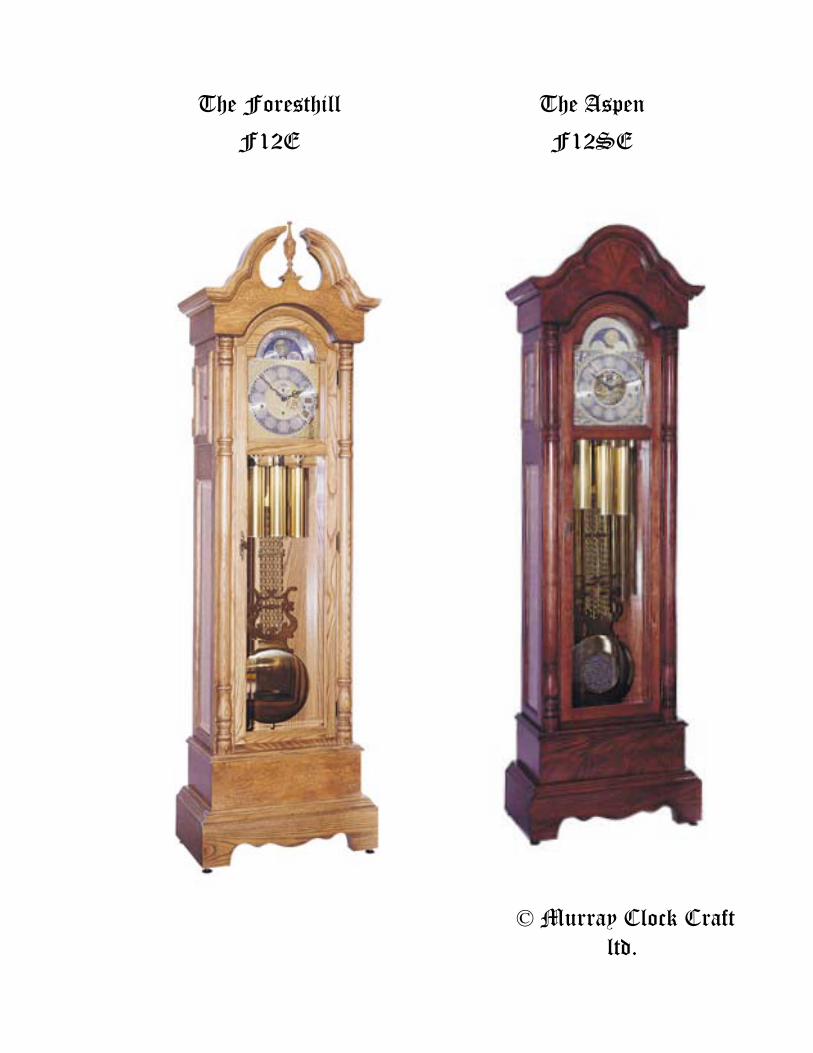
© Murray Clock Craft ltd.
The Aspen
F12SE
The Foresthill
F12E

The Foresthill – F12E and The Aspen – F12SE Clock Plan Guide Building an Heirloom
Thank you for choosing the Murray Clock Craft Kit or plans. All of us on the design and construction team have worked hard to bring you what we believe is the finest product of its kind anywhere. We also believe that you have high expectations for an heirloom-quality finished product. Why else would you begin such a project? These instructions and plans are designed to guide you through all crucial steps, in a way not usually found in other plans. When parts come assembled, we make note of this in the instructions for the-“Kit Builder”, with special TIPS for the “Scratch Builder”. Grandfather clocks are all about beauty, precision and the enduring value of craftsmanship. Our aim is to help you achieve all these things while you have FUN. Some Important Suggestions
The following instructions are mainly reserved for the “Scratch Builder” but should be read by both. The “Kit Builder” shall follow only the italicized instructions unless otherwise instructed. To make reading easier, we have highlighted the passages that pertain to the “Kit Builder”. Note: Paragraphs discussing Some Important Suggestions, Hardware, Mount the Movement and Finishing are common to both.
Before beginning you must adopt a meticulous attitude (the care and attention to detail). This is the fundamental building block which lays the foundation for a successful project. Remember no one will ever know just how fast you put this clock together, or that it only took you a day to slap on some varnish. They will however see the end result, and the time it takes to produce a quality heirloom will prove its’ worth. The following instructions and plans provide information to construct this clock from either a kit or scratch built from the plans. Note: All hard-to-make parts are produced or assembled to facilitate construction, and all screw holes are pre-drilled for the “Kit Builder”. The kit can be built virtually anywhere a flat surface of approximately 85” is found. The “Kit Builder” will still require a well lit area, preferably free of distraction, where dust and some disruption is not a problem (eg: the basement). The following tools are recommended: a hand held sander (we recommend a 5” random orbital sander), a variable speed electric drill (3/8” spade bit, and three or four 1/16” dia. twist drill), a carpenter’s square, and the usual assortment of woodworking hand tools (eg: screwdrivers, clamps and hammer). Although there are many ways to minimize the tools required to finish this project, the “Scratch Builder” will need a well-lit shop equipped with a table-saw, a table–mounted router, a hand held sander (we recommend a 5” random orbital sander), a variable speed electric drill, a carpenter’s square, and the usual assortment of woodworking hand tools. The scratch builder will also need a 3/8” diameter spade bit and 1/16” diameter twist drill as needed at various stages of construction. TIP – Get 3 or 4 of the 1/16” diameter twist drills as they break easily. Pocket holes are used extensively in the kit version of this clock, though you can substitute biscuits, dowels or externally-plugged screws if you’d rather not buy the jig required.
Ideally, your workbench should be as long as the clock is tall. In this case, that’s 85 inches, though you can make-do with a smaller work surface if necessary. You will also need some carpenter’s glue (white, yellow or brown wood). Any formulation is strong enough to hold your clock together forever. Please note that when clamping wood excess glue is squeezed out of the joint. You must be careful not to leave glue residue which will always leave ugly marks on the wood after finishing. The trick is to use just enough glue for strength, with minimal squeeze out. Also when glue does ooze out do not wipe it off even with a damp cloth, as this will drive the glue deep into the wood pores. Instead, wait an hour or two until the glue has formed a skin, then pare off the half hard residue with a sharp chisel. Dealing skillfully with glue squeeze out is one of the most important skills to master for a blotch-free finish on your clock.
1
You will also need to consider clamps, at a minimum you will need about half a dozen, medium sized C-clamps. Another type of clamp (the Quick-Grip) is ideal for this project, since it includes rubber padded jaws that can be tightened with the same hand that is holding the clamp. Pipe clamps are handy for large items, but not essential for this kit. A roll of 1 inch wide masking tape is useful for holding small parts under minimal pressure.
Start work by reading the instruction manual and sorting the main parts according to the material list and Figure 1 - exploded view. Before permanently gluing parts together, it is recommended that the parts are “dry fitted” temporarily together. This may seem like a waste of time, but there are two good reasons for this; Firstly, the experience builds familiarity and confidence for the occasion when glue and screws are applied during final assembly. Secondly, practice really does make perfect, a dry run will show you how to best arrange clamps for an optimal fit and will also point out areas where you may have problems. Whatever you do, don’t skip the dry-fitting stage.
The Kit Builder should lightly sand all parts removed from the box using 150-grit sandpaper prior to dry-fitting. Although you’ll find that the kit parts have all the finished surfaces pre-sanded, the kit does requires a final sanding prior to staining. This is another way to familiarize yourself with the parts prior to construction. The Main Case Assembly (Refer to Figure 1 and 2) The first step is to construct the Main Case Frame Assembly. It is made of horizontal parts (called rails) and vertical members (called stiles) as shown in the plans. Start by cutting the Front Stiles - Left and Right (1), Front Top Arched Rail (2) and Front Bottom Rail (3) (refer to Figure 2 for dimensions) (these are pre-assembled in the kit). Lay parts face-down on your workbench. These need to be joined with dowels, biscuits (53) or pocket screws (51) into a framework that forms the Main Case Frame Assembly. Next, prepare the Side Front and Back Stiles – Left and Right (4 and 5), Side Top Rails – Left and Right (6), Middle Rails – Left and Right (7), and Side Bottom Rails – Left and Right (8) then join these into Left and Right Frame Assemblies (these are pre-assembled in the kit) in the same way as the Main Case Frame Assembly. The Kit Builder will remove the Main Case Frame Assembly from the box and lay it face down on the workbench and notice the tongues that extend from the outside edge of both Left and Right Front Stiles (1). Next, remove the Right and Left Side Frame Assemblies from the box and notice the matching grooves in the Left and Right Side Front Stiles (4). Dry-fit these parts, making certain that the notch for the Back Panel (13) is facing up. Then assemble permanently with glue and clamps using a carpenters’ square to check that the front and side frames are arranged at 90° to each other.
By now you’ve probably noticed that the front frame requires tongues of wood that extend from the outside edges of each stile. These fit into matching grooves in the side frames. Rout these features now, dry-fit the parts to be sure all is well, then assemble permanently with glue and clamps. Use a carpenter’s square to check that the front and side frames are arranged at 90° to each other. Both the Kit Builder and Scratch Builder will perform the following unless otherwise instructed:
The Top and Bottom Back Cleats (9) can be positioned now, as shown in the plans, and screwed in place using 1 1/4”- pocket hole screws (51) driven into pocket holes, securing them to the back of the main case. Though small, you’ll find these strips add a lot of support to your growing clock case.
Next prepare the Bottom and Top Panels (10 and 11) for assembly. These are made of veneered plywood and add even more strength to the case. Just remember that the Bottom Panel (10) needs to have an equal amount of overhang on each side of the Main Case Frame as it’s installed, so the grooves in both Short Foot Moldings – Left and Right (19) will fit over its ends. In fact, temporarily place these moldings over the plywood, just to be sure you’ve located the bottom panel properly.
2
The Middle Back Cleat (12) is next to be installed. It fastens to the inside of the Main Case with glue and pocket screws, dowels or plugged screws driven from the outside. The plans show exactly where the part goes. The purpose of this cleat is to cover the gap between the Back Panel (13) and Top Back Panel (44) that covers the back of the clock. Prepare and install Back Panel (13) now, using No. 6 x 3/4” wood screws (46). Although you’ll want to remove it later for finishing, fastening this panel now adds strength and keeps the cabinet square. Just be sure to drive the screws into 1/16” diameter pilot holes drilled into the Side Back Stiles (5) to prevent splitting. The Base Assembly (Refer to Figure 1)
Both the Kit Builder and Scratch Builder will perform the following unless otherwise instructed:
Fasten the Base Front (14) to the front of the Main Case, at the bottom, using glue and five No. 8 x 1-1/4” wood screws driven from inside. The plans show how the bottom of the base front must be flush with the bottom of the main case stiles. This is one of those times when you’ve got to be especially careful about any glue squeeze out that appears, since it would be hard to remove and disappointingly prominent.
The Long Foot Molding (15) is installed next. It’s a single piece of wood that attaches to the Base Front (14), using glue and three No. 8 x 1-1/4” wood screws (45). Prior to assembly position the Left and Right Short Foot Moldings (16) with the Long Foot Molding (15), so the 45-degree miter joints at the corners are tight. (TIP – The Scratch Builder will notice that the plans show how each miter should be reinforced with a #20 biscuit (53) or several dowels). Even after the foot molding parts are joined with mechanical reinforcement, you’ll find that the joints can often be tightened with clamping pressure across the parts if necessary. Let the parts dry for several hours before moving on to the next stage. Finish up this assembly by adding both Base Sides (17), secured with glue and screws from inside the cabinet as you’ve done before. The Front Base Molding (18) and the Side Base Moldings - Left and Right (19) can now be attached with glue and finishing nails (52). Just go easy on the glue. It doesn’t take much here, and squeeze out would be hard to remove invisibly. Turnings and Columns (Refer to Figure 1)
These parts play an important role in adding character to your project, and many Scratch Builders may not have the experience or equipment to make them. That’s why we offer these and other hard-to-make moldings in ready-to-use form. Call 1-800-268-3181 or visit www.murrayclock.com for more details.
Both the Kit Builder and Scratch Builder will perform the following unless otherwise instructed:
Dry-fit the Bottom Turnings (20), Bottom Columns (21A), Top Columns (21B), Middle Turnings (22) and Top Turnings (23), onto the front of the Main Case as it sits face-up on your workbench. The edges of the columns should be about 3/16” in from the outside edge of the case, but you can adjust this a little bit either way to suit your eye. Temporarily fasten the columns and turnings using clamps, then measure the space to make sure there’s enough room for the door that will fit there later. The Kit Builder may place the pre-assembled door in position to test the fit. If everything looks good, fasten the columns and turnings permanently with screws driven through the pre-drilled holes in the front stiles of the main case. It’s important that you drill 1/16” pilot holes in the back of the turnings and columns to prevent splitting. TIP - Drive screws partially through holes in the front stiles so their points are sticking up just slightly above the surface. Arrange the columns and turnings to your liking, then push them down onto the screw points. When you remove them from the clock, the back surfaces of the parts will be marked in the precise spot for drilling. The Clock Top (Refer to Figure 1)
Both the Kit Builder and Scratch Builder will perform the following unless otherwise instructed:
3
The only difference between The Aspen – F12SE and The Foresthill – F12E is the design and construction of the pediment board assembly on the clock top. Perform the following assembly for the clock you are building:
The Aspen – F12SE Pediment Board Construction (Refer to Figure 1)
The Aspen clock has what’s called a bonnet top, and once again many Scratch Builders may not have the experience or equipment to make them. That’s why we offer these and other hard-to-make moldings in ready-to-use form. Call 1-800-268-3181 or visit www.murrayclock.com for more details.
Both the Kit Builder and Scratch Builder will perform the following unless otherwise instructed:
Join the Top Front Filler Rail (24) and the Front Pediment Board (25A), using glue and screws driven from behind. Next, attach this assembly to the Main Case using more glue and four No. 8 1-1/4” wood screws (45). The Top Side Panels - Left and Right (27) can be installed now, also with glue and screws driven from the back. Make sure the bottom edges of the Top Side Panels (27) align with the routed edge of the bottom of the Front Pediment Board (25A). It is important that this decorative profile continue smoothly all around the clock, across all three parts.
Attach the Front Pediment Molding (28A) and the Top Side Moldings - Left and Right (29A). As usual use glue and screws, but be especially careful to avoid squeeze out. Apply glue sparingly here to prevent glue stains from ruining a good finish, especially if you’ll be applying a wood stain as well as a sealer. The Foresthill – F12E Pediment Board Construction (Refer to Figure 1)
The Legacy clock has what’s called a double-scroll top, and once again, this can be a difficult part to make. That’s why we make a ready-made version of this part available. Call 1-800-268-3181 or visit www.murrayclock.com for more details.
Both the Kit Builder and Scratch Builder will perform the following unless otherwise instructed:
Join the Top Front Filler Rail (24) and the Front Pediment Board (25B), using glue and screws driven from behind. Next, attach this assembly to the Main Case using more glue and four No. 8 x 1-1/4” wood screws (45). The Top Side Panels - Left and Right (27) can be installed now, also with glue and screws driven from the back. Make sure the bottom edges of the Top Side Panels (27) align with the routed edge of the bottom of the Front Pediment Board (25B). It is important that this decorative profile continue smoothly all around the clock, across all three parts.
Attach the Swan Neck Moldings - Left and Right (28B) and the Top Side Moldings - Left and Right (29B). As usual use glue and screws, but be especially careful to avoid squeeze out. Apply glue sparingly here to prevent glue stains from ruining a good finish, especially if you’ll be applying a wood stain as well as a sealer. The Scratch Builder will drill a hole using the 3/8” dia. spade bit, 1-1/4” deep into the Plinth (26B) to accommodate the Finial (26A). Both Scratch Builder and Kit Builder can now position and glue Finial (26A) onto the Plinth (26B) and glue this to the Front Pediment Board (25B). The Door Assembly (Refer to Figure 2) The Scratch Builder will perform the following as the doors are pre-assembled in the Case Kit:
There are several ways to construct the clock's Main Door (31, 32, 33 and 34) and Side Door (35 and 36). The approach shown in the plans uses mitred corners, with biscuits (53) for reinforcement. Depending on your equipment, you can use a more traditional stile-and-rail joinery, with mortise and tenons or dowels. As long as the overall door size is correct, anything goes (refer to the plans for dimensions and construction details).
4

Hardware Installation (Refer to Figure 1) Both the Kit Builder and Scratch Builder will perform the following unless otherwise
instructed: Now is the time to install hinges (49), lock with key (47 and 48), door pulls (54), door bullet
catch (55) and other hardware parts, although these will be removed later to facilitate finishing. Start with the door hinges (49). The plan shows that three are required along the right-hand side of the main door, one each 2” from the top and bottom ends of the door, and one hinge in the center. The Kit Builder will place the lock on the back of the case door in position over the pre-drilled keyhole opening. The Scratch Builder will position the lock on the back of the door, trace it, then drill the keyhole opening. Next, either builder places the key into the lock, then pushes it to the top of the hole in the door. This locates the lock mechanism properly for installation. Mark screw hole locations, then use a 1/16” drill bit to create pilot holes for the lock mounting screws. The metal part that covers the key hole on the outside of the door is called an escutcheon plate (50), and although it may be tempting to put it on now, better wait until you’ve applied a finish. Since it’s held on with small nails, it’s hard to get off again.
Next, fasten a pair of hinges (49) to each Side Door, then place them on the clock case and lightly trace the hinge outline onto the wood. Remove the doors, replace the hinges in their old spots, then mark where you need to drill 1/16” diameter pilot holes in the case for the hinge mounting screws.
Grandfather clocks should sit straight and wobble-free, even if the floor they’re resting on isn’t perfectly level. That’s why your clock should be fitted with four height adjusters (56). You’ll need to drill a 3/8” diameter hole at each of the four corners of the base to install these. The plans show location details, but there’s something else you need to know. The best adjusters thread into what are called T-nuts. These have small spikes around the outside that hold them to the clock, and you should pre-drill 1/16-inch pilot holes for these to avoid splitting the wood. You may also want to apply 5 minute epoxy glue around the outside of each T-nut, so there’s no chance they’ll come out. Mount the Movement (Refer to Figure 1)
Both the Kit Builder and Scratch Builder will perform the following unless otherwise instructed:
It’s now time to work on the parts that will support your clock movement. It’s best to install these temporarily until the movement has been placed in position and tested. It’s important that the clock face, the Dial Frame Panel (37) and the chime rods of the clock movement all line up properly. Start work by preparing and fastening the Dial Frame Cleats (38) to the inside of the Front Stiles (1). These cleats should be pushed up tight against the underside of the Top Panel (11), with their grooves facing outward, butting against the Front Stiles (1). Dial Frame Panel (37) can be added later, after the movement has been positioned.
The clock movement itself sits on a kind of shelf made of three parts: the Movement Mount (39), and the Upper and Lower Side Cleats (40 and 41). Assemble these parts into a single unit called the Movement Shelf Assembly, then fasten it to the inside of the clock case. Depending on the movement you’re using, the position of the movement shelf varies. For the Hermle 8-day Triple Chime Cable Drive (item #HCL3T) the shelf must be positioned 5/16” down from the top of the Middle Rails (7). The Hermle 8-day Triple Chime Chain Drive (item #H3T) and the Hermle 8-day Westminster Chime Cable Drive (item #HC3) require this dimension to be slightly lower, 7/16” down from the top of the Middle Rails (7). In all cases, the movement shelf should be 1-1/4” back from the Front Stiles (1).
The Chime Panel (42) and Chime Panel Side Cleats (43) hold the chime assembly, and now’s the time to secure these parts to the Top Back Panel (44). This is where some trial fitting comes into play. Start by positioning the clock movement in place, with dial attached. This will allow you to position the Chime Rods onto the chime block assembly in the appropriate location so they get struck properly by the hammers at the back of the clock movement. The Dial Frame Panel (37)
5
should be fastened temporarily in place now using four No. 6 x 3/4“ wood screws (46) to center the movement. The Top Back Panel (44) can now be temporarily fastened using eight No. 6 x 3/4” wood screws (46) to position the chime rods and chime rod panel. Be sure to drill 1/16” pilot holes to avoid splitting the wood.
For further instructions and more information on movement mounting refer to the Movement Mounting Instructions included with your movement. Finishing
Both the Kit Builder and Scratch Builder will perform the following unless otherwise instructed:
The quality of finish you apply to your clock is crucial. You can do a great job with everything else, but if the finish is rough and ugly, the result is spoiled. Start by removing all hardware, clock works and clock face, before giving everything a final hand sanding using 180-grit paper. You’ll find a sharp chisel handy for removing blobs of stray glue you missed earlier. Vacuum all parts thoroughly and your surrounding work space. Everything must be surgically clean for best results. Although there are many ways to finish your clock, urethane is one of the most popular options for people working in their homes. All major wood finishing companies have produced oil-based formulations for years, but water-based versions are gaining in popularity. Besides the fact that they clean up easily with water before they’re dry, water-based products also are remarkably low in odour and fast drying. But rapid drying speed leads to trouble with brands that form bubbles as they are brushed on. It is possible that these bubbles will harden in place and degrade your results. A slow, not too energetic brushing action is one solution to the problem, but an even better one is to use a foam finishing applicator. These typically have a wooden or plastic handle with a porous foam head instead of bristles. The foam kicks up fewer bubbles than an ordinary brush. Some brands of urethane are also considerably more bubble prone than others. In shop tests published in a leading woodworking magazine, two brands of water-based urethanes stood out from the rest: ICI Quick Drying Varnish (available at Glidden paint stores) and Flecto line are considerable less likely to form hardened bubbles than other brands.
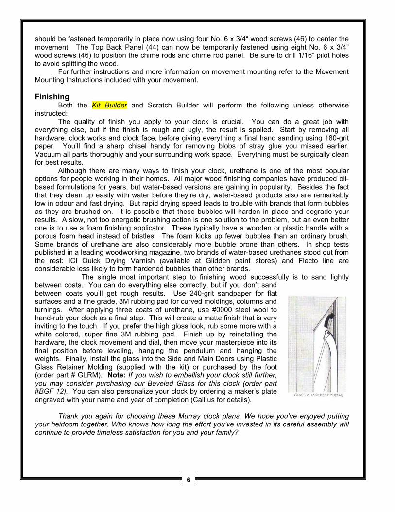
The single most important step to finishing wood successfully is to sand lightly between coats. You can do everything else correctly, but if you don’t sand between coats you’ll get rough results. Use 240-grit sandpaper for flat surfaces and a fine grade, 3M rubbing pad for curved moldings, columns and turnings. After applying three coats of urethane, use #0000 steel wool to hand-rub your clock as a final step. This will create a matte finish that is very inviting to the touch. If you prefer the high gloss look, rub some more with a white colored, super fine 3M rubbing pad. Finish up by reinstalling the hardware, the clock movement and dial, then move your masterpiece into its final position before leveling, hanging the pendulum and hanging the weights. Finally, install the glass into the Side and Main Doors using Plastic Glass Retainer Molding (supplied with the kit) or purchased by the foot (order part # GLRM). Note: If you wish to embellish your clock still further, you may consider purchasing our Beveled Glass for this clock (order part #BGF 12). You can also personalize your clock by ordering a maker’s plate engraved with your name and year of completion (Call us for details).
Thank you again for choosing these Murray clock plans. We hope you’ve enjoyed putting
your heirloom together. Who knows how long the effort you’ve invested in its careful assembly will continue to provide timeless satisfaction for you and your family?
6
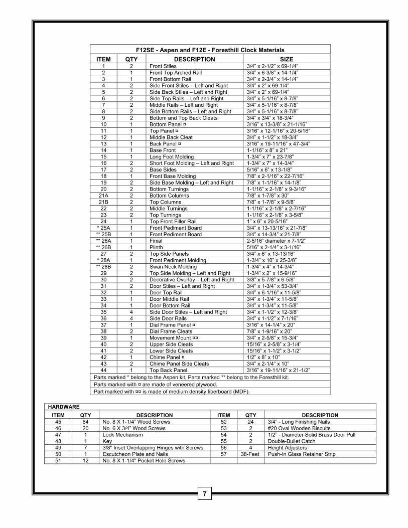
F12SE - Aspen and F12E - Foresthill Clock Materials
ITEM QTY DESCRIPTION SIZE 1 2 Front Stiles 3/4” x 2-1/2” x 69-1/4” 2 1 Front Top Arched Rail 3/4” x 6-3/8” x 14-1/4” 3 1 Front Bottom Rail 3/4” x 2-3/4” x 14-1/4” 4 2 Side Front Stiles – Left and Right 3/4” x 2” x 69-1/4” 5 2 Side Back Stiles – Left and Right 3/4” x 2” x 69-1/4” 6 2 Side Top Rails – Left and Right 3/4” x 5-1/16” x 8-7/8” 7 2 Middle Rails – Left and Right 3/4” x 5-1/16” x 8-7/8” 8 2 Side Bottom Rails – Left and Right 3/4” x 5-1/16” x 8-7/8” 9 2 Bottom and Top Back Cleats 3/4” x 3/4” x 18-3/4”
10 1 Bottom Panel ¤ 3/16” x 13-3/8” x 21-1/16” 11 1 Top Panel ¤ 3/16” x 12-1/16” x 20-5/16” 12 1 Middle Back Cleat 3/4” x 1-1/2” x 18-3/4” 13 1 Back Panel ¤ 3/16” x 19-11/16” x 47-3/4” 14 1 Base Front 1-1/16” x 8” x 21” 15 1 Long Foot Molding 1-3/4” x 7” x 23-7/8” 16 2 Short Foot Molding – Left and Right 1-3/4” x 7” x 14-3/4” 17 2 Base Sides 5/16” x 6” x 13-1/8” 18 1 Front Base Molding 7/8” x 2-1/16” x 22-7/16” 19 2 Side Base Molding – Left and Right 7/8” x 1-1/16” x 14-1/8” 20 2 Bottom Turnings 1-1/16” x 2-1/8” x 9-3/16”
21A 2 Bottom Columns 7/8” x 1-7/8” x 30” 21B 2 Top Columns 7/8” x 1-7/8” x 9-5/8” 22 2 Middle Turnings 1-1/16” x 2-1/8” x 2-7/16” 23 2 Top Turnings 1-1/16” x 2-1/8” x 3-5/8” 24 1 Top Front Filler Rail 1” x 6” x 20-5/16”
* 25A 1 Front Pediment Board 3/4” x 13-13/16” x 21-7/8” ** 25B 1 Front Pediment Board 3/4” x 14-3/4” x 21-7/8” ** 26A 1 Finial 2-5/16” diameter x 7-1/2” ** 26B 1 Plinth 5/16” x 2-1/4” x 3-1/16”
27 2 Top Side Panels 3/4” x 6” x 13-13/16” * 28A 1 Front Pediment Molding 1-3/4” x 10” x 25-3/8” ** 28B 2 Swan Neck Molding 1-3/4” x 4” x 14-3/4”
29 2 Top Side Molding – Left and Right 1-3/4” x 2” x 15-9/16” 30 2 Decorative Overlay – Left and Right 3/8” x 5-7/8” x 6-5/8” 31 2 Door Stiles – Left and Right 3/4” x 1-3/4” x 53-3/4” 32 1 Door Top Rail 3/4” x 6-1/16” x 11-5/8” 33 1 Door Middle Rail 3/4” x 1-3/4” x 11-5/8” 34 1 Door Bottom Rail 3/4” x 1-3/4” x 11-5/8” 35 4 Side Door Stiles – Left and Right 3/4” x 1-1/2” x 12-3/8” 36 4 Side Door Rails 3/4” x 1-1/2” x 7-1/16” 37 1 Dial Frame Panel ¤ 3/16” x 14-1/4” x 20” 38 2 Dial Frame Cleats 7/8” x 1-9/16” x 20” 39 1 Movement Mount ¤¤ 3/4” x 2-5/8” x 15-3/4” 40 2 Upper Side Cleats 15/16” x 2-5/8” x 3-1/4” 41 2 Lower Side Cleats 15/16” x 1-1/2” x 3-1/2” 42 1 Chime Panel ¤ 1/2” x 8” x 10” 43 2 Chime Panel Side Cleats 3/4” x 2-1/4” x 10” 44 1 Top Back Panel 3/16” x 19-11/16” x 21-1/2”
Parts marked * belong to the Aspen kit, Parts marked ** belong to the Foresthill kit. Parts marked with ¤ are made of veneered plywood. Part marked with ¤¤ is made of medium density fiberboard (MDF).
HARDWARE
ITEM QTY DESCRIPTION ITEM QTY DESCRIPTION 45 64 No. 8 X 1-1/4” Wood Screws 52 24 3/4” - Long Finishing Nails 46 20 No. 6 X 3/4” Wood Screws 53 2 #20 Oval Wooden Biscuits 47 1 Lock Mechanism 54 2 1/2” - Diameter Solid Brass Door Pull 48 1 Key 55 2 Double-Bullet Catch 49 7 3/8" Inset Overlapping Hinges with Screws 56 4 Height Adjusters 50 1 Escutcheon Plate and Nails 57 38-Feet Push-In Glass Retainer Strip 51 12 No. 8 X 1-1/4" Pocket Hole Screws
7
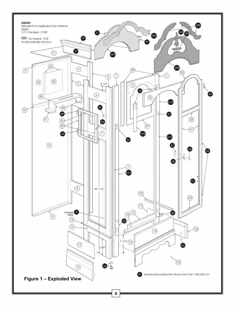
Figure 1 – Exploded View
8
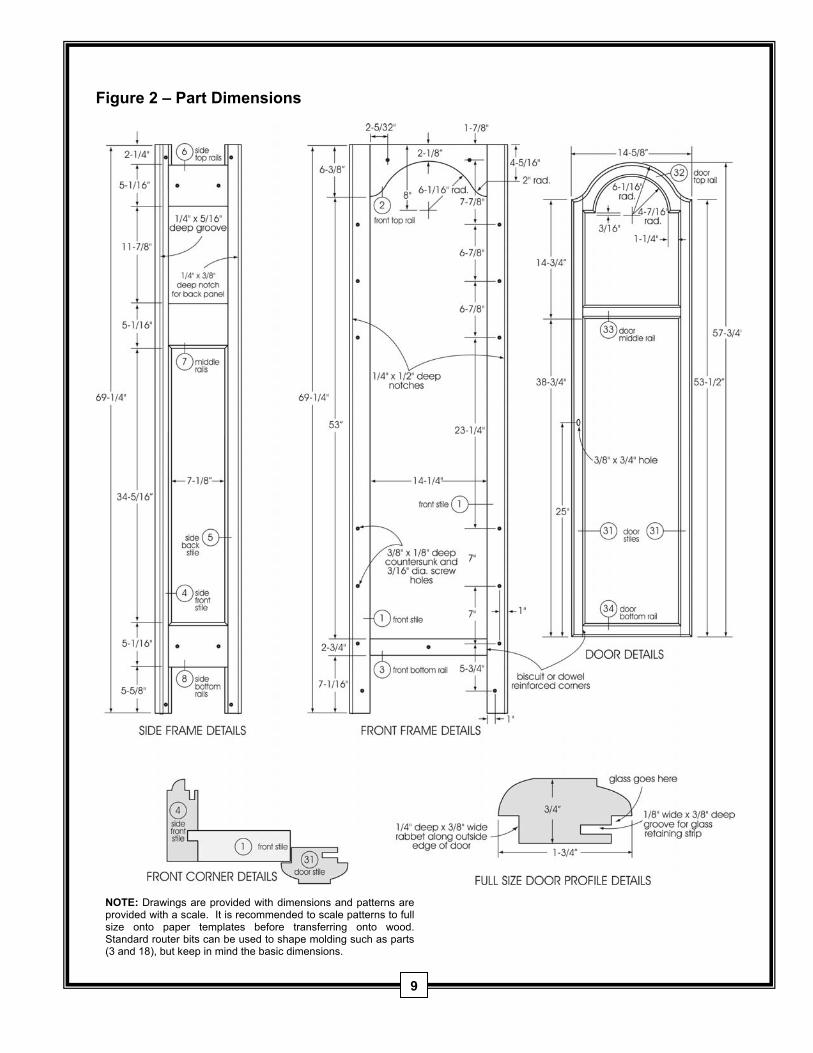
Figure 2 – Part Dimensions
NOTE: Drawings are provided with dimensions and patterns are
provided with a scale. It is recommended to scale patterns to full size onto paper templates before transferring onto wood. Standard router bits can be used to shape molding such as parts (3 and 18), but keep in mind the basic dimensions.
9
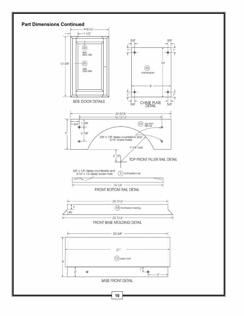
Part Dimensions Continued
10
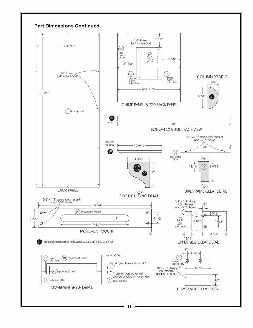
Part Dimensions Continued
11
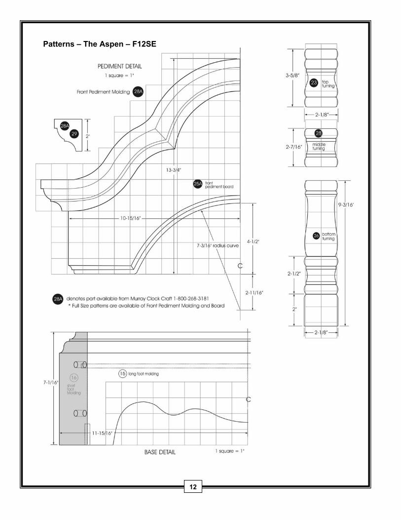
Patterns – The Aspen – F12SE
12
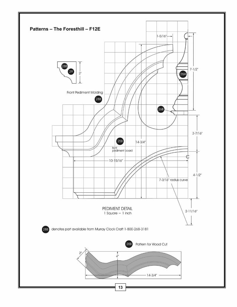
Patterns – The Foresthill – F12E
13