Embed Size (px)
Citation preview
Building a conference centeror
triangulating a surfaceGeza Makay
Bolyai Institute, University of Szeged, HungaryAradi vertanuk tere 1, Szeged, Hungary, 6720
[email protected]://www.math.u-szeged.hu/˜makay/
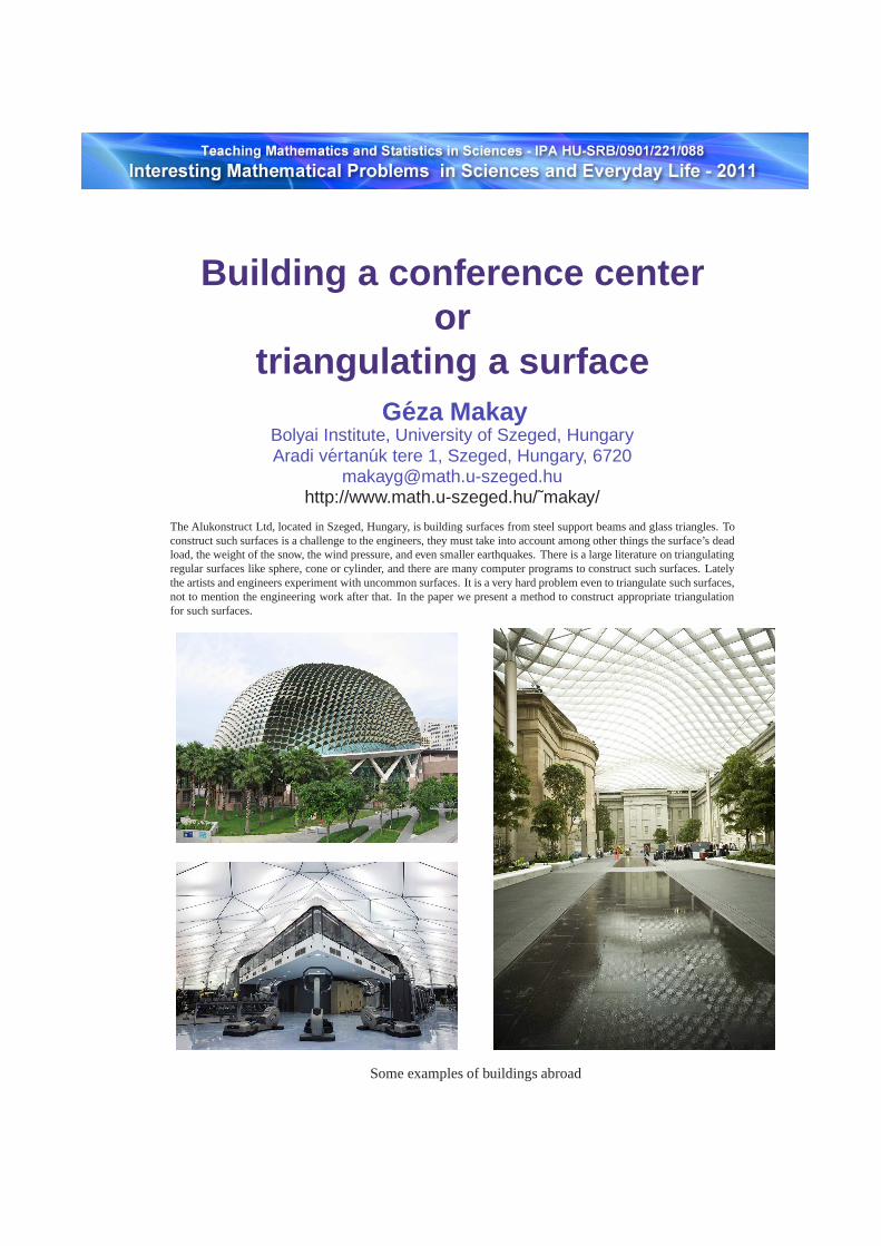
The Alukonstruct Ltd, located in Szeged, Hungary, is building surfaces from steel support beams and glass triangles. Toconstruct such surfaces is a challenge to the engineers, they must take into account among other things the surface’s deadload, the weight of the snow, the wind pressure, and even smaller earthquakes. There is a large literature on triangulatingregular surfaces like sphere, cone or cylinder, and there are many computer programs to construct such surfaces. Latelythe artists and engineers experiment with uncommon surfaces. It is a very hard problem even to triangulate such surfaces,not to mention the engineering work after that. In the paper we present a method to construct appropriate triangulationfor such surfaces.
Some examples of buildings abroad
2 G. Makay
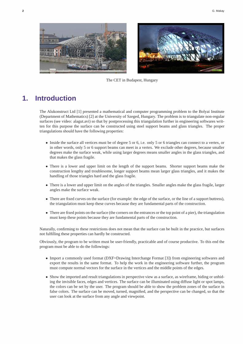
The CET in Budapest, Hungary
1. Introduction
The Alukonstruct Ltd [1] presented a mathematical and computer programming problem to the Bolyai Institute(Department of Mathematics) [2] at the University of Szeged, Hungary. The problem is to triangulate non-regularsurfaces (see video: alagut.avi) so that by postprocessingthis triangulation further in engineering softwares writ-ten for this purpose the surface can be constructed using steel support beams and glass triangles. The propertriangulations should have the following properties:
• Inside the surface all vertices must be of degree 5 or 6, i.e. only 5 or 6 triangles can connect to a vertex, orin other words, only 5 or 6 support beams can meet in a vertex. We exclude other degrees, because smallerdegrees make the surface weak, while using larger degrees means smaller angles in the glass triangles, andthat makes the glass fragile.
• There is a lower and upper limit on the length of the support beams. Shorter support beams make theconstruction lengthy and troublesome, longer support beams mean larger glass triangles, and it makes thehandling of those triangles hard and the glass fragile.
• There is a lower and upper limit on the angles of the triangles. Smaller angles make the glass fragile, largerangles make the surface weak.
• There are fixed curves on the surface (for example: the edge ofthe surface, or the line of a support buttress),the triangulation must keep these curves because they are fundamental parts of the construction.
• There are fixed points on the surface (the corners on the entrances or the top point of a pier), the triangulationmust keep these points because they are fundamental parts ofthe construction.
Naturally, confirming to these restrictions does not mean that the surface can be built in the practice, but surfacesnot fulfilling these properties can hardly be constructed.
Obviously, the program to be written must be user-friendly,practicable and of course productive. To this end theprogram must be able to do the followings:
• Import a commonly used format (DXF=Drawing Interchange Format [3]) from engineering softwares andexport the results in the same format. To help the work in the engineering software further, the programmust compute normal vectors for the surface in the vertices and the middle points of the edges.
• Show the imported and result triangulations in perspectiveview as a surface, as wireframe, hiding or unhid-ing the invisible faces, edges and vertices. The surface canbe illuminated using diffuse light or spot lamps,the colors can be set by the user. The program should be able toshow the problem zones of the surface infalse colors. The surface can be moved, turned, magnified, and the perspective can be changed, so that theuser can look at the surface from any angle and viewpoint.
Building a conference center or triangulating a surface 3
• After setting the parameters for the triangulations and starting the generation, the program must create astatistics about the generated triangulations, so that an experienced engineer will be able to choose theappropriate triangulations for further processing and eventual building.
• The triangulation must be editable by the user: he can add or delete vertices, edges and triangles while theprogram keeps the structure intact. The user can also make the program move the vertices on the surfaceautomatically so that the limits on the length of the supportbeams and the angles fit better to the specifiedparameters.
2. The fundamental algorithm
There are only a few methods in the literature about triangulating non-regular surfaces, and even those focus ononly one or two of the above conditions (see, for example the Delaunay triangulation [4]). We did not find a paperconcerning the degree of the vertices inside the surface. So, a new algorithm must be created that does take allconditions into account. Let us consider the problem from this point of view and work out the basic methods forsolving this problem.
The surface is in the 3 dimensional space, so we will use 3 dimensional points for the vertices, two such pointsdetermine an edge, and 3 points connected pairwise determine a triangle.
We receive the surface in triangulated form, it would be veryhard to handle it in any other format. This means thatthe original surface (constructed for example from a function’s graph or transformations) sustained a modification(the triangulation) and it became worse, not original. Our first question is: what was the original surface, whatsurface should we triangulate? Naturally, we work with triangulation, so we must refine the given triangulation insome way to approximate the original surface better. We can do this using the following trick: we can break upall triangles into 4 by connecting the midpoints of its edges. Then we move the newly introduced vertices so thatthe plane angle of all triangles and their adjacent triangles will be about the same: this ensures that the surfacewill appear to be smoother. During this moving we must keep the fixed curves on the surface: we move the pointson the fixed curves in the plane defined locally by the curve, while we move all other vertices orthogonal to thesurface. This method is called the refinement of the surface.By executing this refinement several times we can geta fine enough triangulation of the surface, which will approximate the original surface well. Another advantageof using this refinement is that the would-be triangulation will use vertices from this refined triangulation. Thisensures that the vertices of the new triangulation are on thesurface, and moving them around does not distort thesurface provided by the new triangulation (see videos: ikozaeder.avi, tokfinom.avi).
Now the problem can be formulated as the following: which vertices of the refined triangulation should be inthe new triangulation, and which ones should be connected toget an appropriate triangulation? We tried severalmethods, most of the were based on distributing the verticesevenly on the surface (by maximizing the minimumdistance between the points, for example), then fitting the faces on these points so that they satisfy the conditions(for example, by taking the convex hull of the points). Thesemethods did not work: they did not agree withthe condition on the degree of the vertices. The finally working method was to create the triangulation by addingtriangles one at a time and keeping the degrees to be 5 or 6 only. During this construction we exercise extra cautionnot to step over fixed edges and points. Also, the program automatically moves the new vertices around so that thelimits on the length of the beams and the angles match better to the conditions.
3. The mathematical basics and theorems used
It was a surprise, that no higher mathematics is needed to solve the problem: all theorems are covered in highschools or understandable by high school students.
Since the condition on the degrees of vertices seems to be themost restricting one among the conditions, let uslook at it a little closer. We will user Euler’s Polyhedron Theorem [5]. It states that a polyhedron withv vertices,e edges andf faces must satisfy the equalityv + f = e + 2. We can deduce from this a (for me very surprising)new
4 G. Makay
Theorem 1 If a polyhedron contains only triangles and all of its vertices are of degree 5 or 6, then it has exactly12 vertices of degree 5.
Proof. Let us denote byv5 andv6 the number of vertices of degree 5 and 6, respectively. Then we havev = v5+v6.Let us compute the number of edges by two different methods. If we sum up the degrees of all vertices, we countthe number of edges twice, since all edges have two ends, so wehave5v5 + 6v6 = 2e. Also, all faces have 3edges, so 3 times the number of faces is also the number of edges twice, since an edge is computed twice on thefaces joined by the edge:3f = 2e. We put Euler’s Polyhedron Theorem beside these equalitiesand we have aliner system of equations:
5v5 + 6v6 = 2e (1)
3f = 2e (2)
v5 + v6 + f = e + 2 (3)
Computing6 · (3) − (1) − 2 · (2) we get the desired result:v5 = 12.
Although it is not relevant in solving our problem, how many vertices of degree 6 are possible, but it is an inter-esting question for a mathematician. It turns out that this number can be 0 or at least 2, only 1 vertex of degree 6is not possible.
The icosahedron [6] is a good example for this theorem. It has20 regular triangles and 12 vertices of degree 5.If we apply the refinement explained above to this polyhedron, all new vertices will be of degree 6, and by doingseveral refinement we will get an approximate of the sphere. This is the easiest way to triangulate a sphere.
This theorem shows why the condition on the degrees is the most limiting. Naturally, we do not work withcomplete polyhedrons, our surfaces have holes in them, but it modifies the statement only slightly: we can have atmost 12 vertices of degree 5 inside the surface. Also, a little drawing and experimenting shows that the surface tobe triangulated must be part of the surface of a (more or less)convex polyhedron.
In the 3 dimensional Cartesian coordinate system we use the following basic notations and relations:
• The length of a vector(x, y, z) is ‖(x, y, z)‖ =√
x2 + y2 + z2. The distance of two points is
d((x1, y1, z1), (x2, y2, z2)) = ‖(x1 − x2, y1 − y2, z1 − z2)‖ =√
(x1 − x2)2 + (y1 − y2)2 + (z1 − z2)2
• The scalar product of two vectors [7] is
(x1, y1, z1) · (x2, y2, z2) = x1x2 + y1y2 + z1z2 = ‖(x1, y1, z1)‖ · ‖(x2, y2, z2)‖ · cosα,
whereα is the angle of the two vectors;
• The vectorial product of two vectors [8] is
(x1, y1, z1) × (x2, y2, z2) = (y1z2 − y2z1, z1x2 − z2x1, x1y2 − x2y1),
which is a vector orthogonal to the vectors(x1, y1, z1) and(x2, y2, z2), its direction is given by the right-hand-rule, and its length is
‖(x1, y1, z1)‖ · ‖(x2, y2, z2)‖ · sin α,
whereα is the angle of the two vectors;
Using the scalar product and the length of the vectors, we cancompute length of the edges and the angles of thetriangles. We use these to distribute the vertices on the refined surface so that the edges’ lengths and angles matchbetter to the conditions. To this end we compute a weighted sum (the goal function) of the deviation of the lengthfrom the expected length of the edges meeting in a vertex and the deviation of the angles from60◦ of the triangleshaving that vertex as a point. We try to decrease this sum by moving that vertex to one of its neighbors on the
Building a conference center or triangulating a surface 5
refined surface and we apply this method to all vertices of thetriangulation. We repeat this procedure until wecannot move any vertex without increasing the goal function, so we found a minimal value for the goal functionfor the actual triangulation. Since we tried to decrease thedeviances from the best values in the weighted sum,this make our triangulation ”better”, it fits better to the conditions.
If we compute the vectorial product of two edges of a triangle, and divide that vector with its length (we normalizeit), we will get a normal vector for that face. If we compute the sum of the normal vectors of two adjoiningtriangles and normalize that vector, we arrive at the normalvector of the connecting edge. To get a normal vectorfor the surface in a vertex, we normalize the sum of the normalvectors of the triangles having that vertex as apoint. We determine these normal vectors so that they point outwards from the surface: we fix a direction to onetriangle and by setting the adjoining triangle’s normal vectors appropriately, the normal vectors will all point to thesame direction (inwards or outwards). Then either the user changes the directions of all normal vectors by ”hand”or the program (assuming that the surface is more of a roof than a floor) sets it automatically.
How can one compute the effect of a spot lamp to the surface? Ifa spot lamp’s light is orthogonal to the surface,then its effect is maximal. The larger the angle of the surface’s normal vector and the vector pointing from thecenter of gravity of the triangle to the spot lamp, the smaller lighting the triangle will receive from the lamp; ifthis angle is larger than90◦, then the spot lamp does not illuminate the outside part of the triangle. This anglecan be computed easily using the scalar product. Using this angle the program computes a weighted mean of twocolors: one is the (usually) darker diffuse color, and the other is the fully illuminated face’s color. One can evensimulate colored spotlights: the diffuse color is the colorof the surface, the fully illuminated color is the effect ofthe spotlight’s color on the surface. We can use the computedcolor to display the perspective projection of thetriangle.
And now to one of the most interesting parts of the program: how can one compute the perspective projection of atriangle, and how can we handle the hiding of invisible facesand edges? The second part of the question is easier,we answer that first. We look at the surface from a point in the 3dimensional space. We can compute the distanceof the center of gravity of the triangle from this point, and order the faces by descending order of this distance. Wedraw the triangle with the largest distance first and proceedto the triangles with smaller distances: in this way thecloser triangles naturally cover the further triangles andedges. We draw the edges and vertices together with theirappropriate triangles, so their coverage will be fine, too.
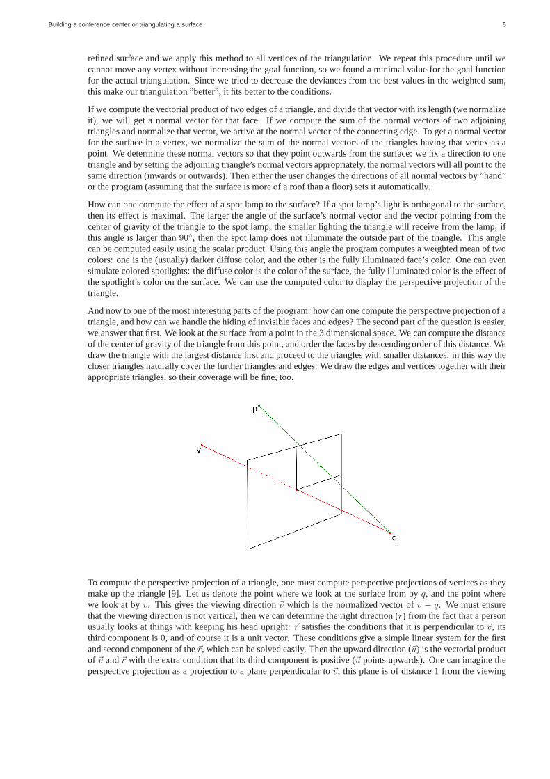
To compute the perspective projection of a triangle, one must compute perspective projections of vertices as theymake up the triangle [9]. Let us denote the point where we lookat the surface from byq, and the point wherewe look at byv. This gives the viewing direction~v which is the normalized vector ofv − q. We must ensurethat the viewing direction is not vertical, then we can determine the right direction (~r) from the fact that a personusually looks at things with keeping his head upright:~r satisfies the conditions that it is perpendicular to~v, itsthird component is 0, and of course it is a unit vector. These conditions give a simple linear system for the firstand second component of the~r, which can be solved easily. Then the upward direction (~u) is the vectorial productof ~v and~r with the extra condition that its third component is positive (~u points upwards). One can imagine theperspective projection as a projection to a plane perpendicular to~v, this plane is of distance 1 from the viewing
6 G. Makay
pointq, its vertical axis is~u and the horizontal axis is~r. The projected point is the intersection of this plane withthe line connectingq and the point to be projected and we can express the projectedpoint as a linear combinationof ~r and~u. So, we first check that the point is in front of us:(p − q) · ~v > 0, then its perspective projection is
((p − q) · ~r, (p − q) · ~u)/((p − q) · ~v).
This formula projects the viewed pointv to the two dimensional point(0, 0), hence we need to translate andmagnify the resulting 2 dimensional points so that(0, 0) goes to the center of the screen and the obtained image islarge enough to view. One can change the perspective by moving the viewing pointq closer to the viewed pointv.To rotate the image we change the viewing pointq, to move the image we change the viewed pointv, but we keeptheir distance constant as it would change the perspective too. Now we can show the user any triangulation fromany point in any perspective.
Now we arrived at the heart of the problem: how can we triangulate a surface given by a fine enough triangulationso that it confirms to the given conditions? We now know that weadd one triangle at a time so that we payattention to the condition on the degrees and we try to keep the edges’ lengths and the angles in the given intervalsby moving the vertices around. So let us make a triangle on thesurface and we covered part of the surface by atriangle. This triangle has 3 external edges, edges where the surface still continues. We construct a new triangleso that the new triangle has one of this external edges as an edge of its own, and we continue this procedure aslong as we can find external edges in our triangulation. If there are no external edges, then we are finished withthe triangulation of the surface. But how can we add a new triangle to the existing triangulation?
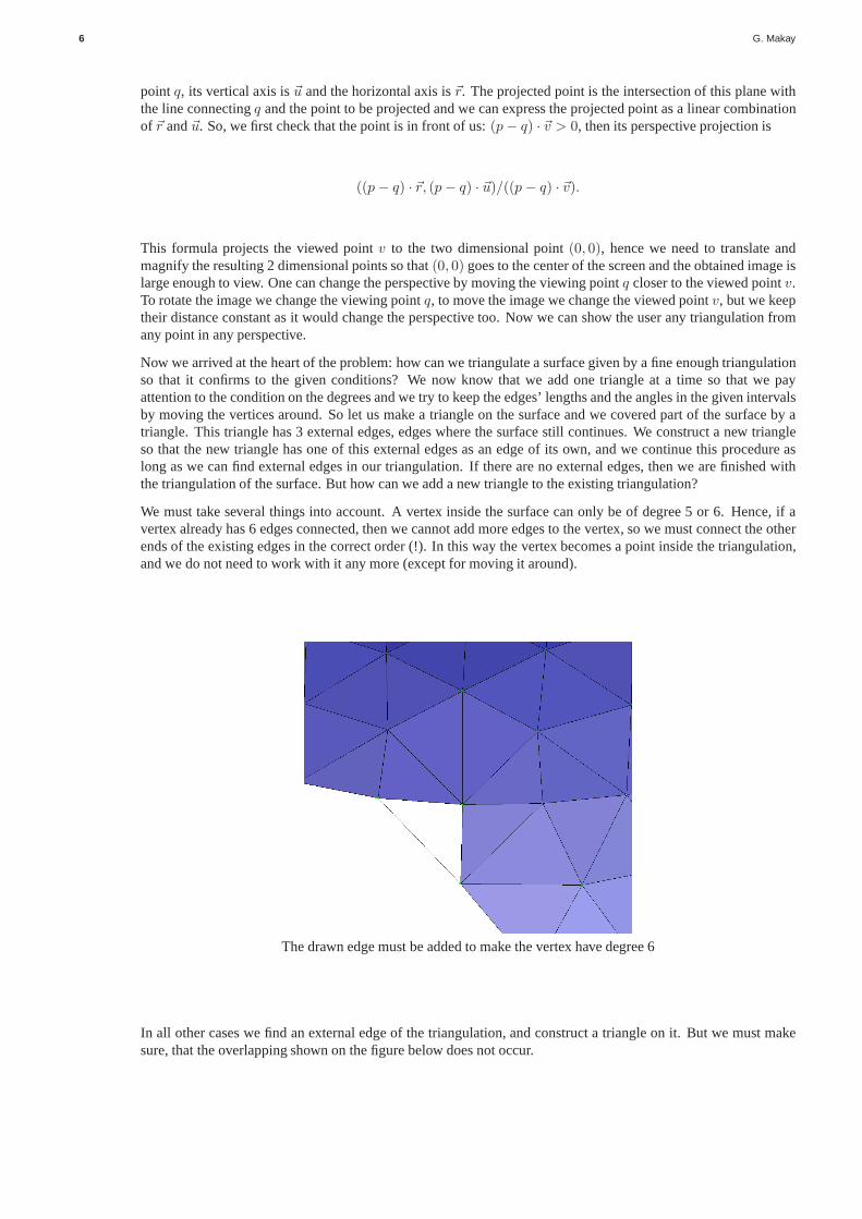
We must take several things into account. A vertex inside thesurface can only be of degree 5 or 6. Hence, if avertex already has 6 edges connected, then we cannot add moreedges to the vertex, so we must connect the otherends of the existing edges in the correct order (!). In this way the vertex becomes a point inside the triangulation,and we do not need to work with it any more (except for moving itaround).
The drawn edge must be added to make the vertex have degree 6
In all other cases we find an external edge of the triangulation, and construct a triangle on it. But we must makesure, that the overlapping shown on the figure below does not occur.
Building a conference center or triangulating a surface 7
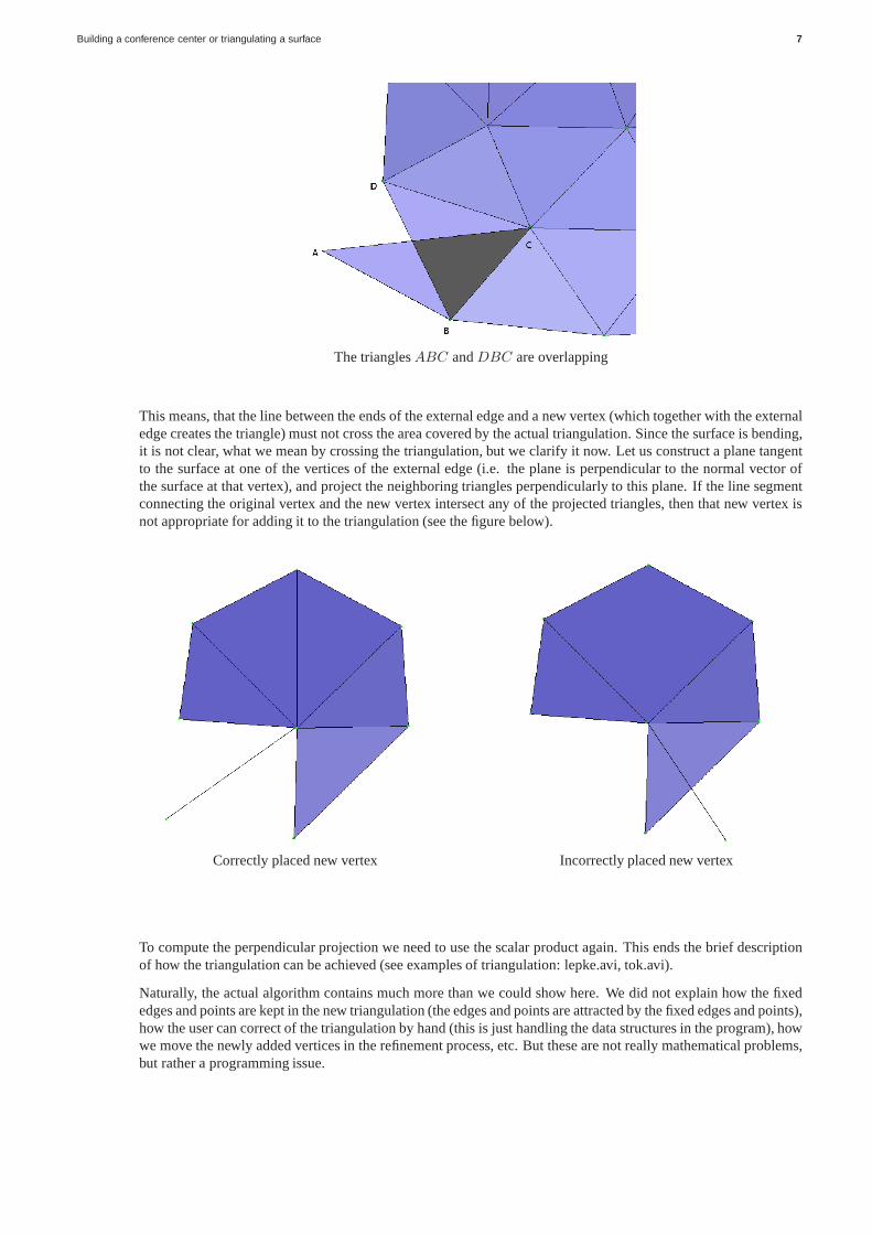
The trianglesABC andDBC are overlapping
This means, that the line between the ends of the external edge and a new vertex (which together with the externaledge creates the triangle) must not cross the area covered bythe actual triangulation. Since the surface is bending,it is not clear, what we mean by crossing the triangulation, but we clarify it now. Let us construct a plane tangentto the surface at one of the vertices of the external edge (i.e. the plane is perpendicular to the normal vector ofthe surface at that vertex), and project the neighboring triangles perpendicularly to this plane. If the line segmentconnecting the original vertex and the new vertex intersectany of the projected triangles, then that new vertex isnot appropriate for adding it to the triangulation (see the figure below).
Correctly placed new vertex Incorrectly placed new vertex
To compute the perpendicular projection we need to use the scalar product again. This ends the brief descriptionof how the triangulation can be achieved (see examples of triangulation: lepke.avi, tok.avi).
Naturally, the actual algorithm contains much more than we could show here. We did not explain how the fixededges and points are kept in the new triangulation (the edgesand points are attracted by the fixed edges and points),how the user can correct of the triangulation by hand (this isjust handling the data structures in the program), howwe move the newly added vertices in the refinement process, etc. But these are not really mathematical problems,but rather a programming issue.
8 G. Makay
References
[1] Alukonstrukt Ltd: http://www.alukonstrukt.hu/
[2] Bolyai Institute: http://www.math.u-szeged.hu/
[3] DXF: http://usa.autodesk.com/adsk/servlet/item?siteID=123112&id=12272454&linkID=10809853
[4] Delaunay triangulation: http://en.wikipedia.org/wiki/Delaunay triangulation
[5] Euler’s Polyhedron Theorem: http://en.wikipedia.org/wiki/Euler characteristic
[6] Icosahedron: http://en.wikipedia.org/wiki/Icosahedron
[7] Scalar product: http://en.wikipedia.org/wiki/Dotproduct
[8] Vectorial product: http://en.wikipedia.org/wiki/Crossproduct
[9] Perspective projection: http://en.wikipedia.org/wiki/Perspectiveprojection#Perspectiveprojection
[10] Videos, VRML files: http://www.math.u-szeged.hu/˜makay/avis/
![Building a conference center or triangulating a · PDF file2 G. Makay The CET in Budapest, Hungary 1. Introduction The Alukonstruct Ltd [1] presented a mathematical and computer programming](https://img.pdfslide.us/doc/110x75/5aafb5d87f8b9aa8438da6b0/building-a-conference-center-or-triangulating-a-g-makay-the-cet-in-budapest-hungary.jpg)