Embed Size (px)
Citation preview
ALARM KIT
BUILD YOUR OWN ALARM CIRCUITKit-ABRA-101
• MasteryoursituationalawarenesswiththeAbraAlarmKit.
• AssembleyourveryownAlarmKitandbewarnedofanyopeningdoororwindow.• Highintensitypiezoelectricalarm.• LocalandRemotealarmswitches.• LearnhowaSiliconControlled
Rectifierworks.• Batteryoperated
forsafety.
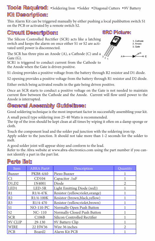
Kit Description:This Alarm Kit can be triggered manually by either pushing a local pushbutton switch S1 on the PCB or activated by a remote switch S2.
Circuit Description: The Silicon Controlled Rectifier (SCR) acts like a latching switch and keeps the alarm on once either S1 or S2 are acti-vated until power is disconnected.The SCR has three pins an Anode (A), a Cathode (C) and a Gate (G). SCR1 is triggered to conduct current from the Cathode to the Anode when the Gate is driven positive. S1 closing provides a positive voltage from the battery through R2 resistor and D1 diode.S2 opening provides a positive voltage from the battery through R1 resistor and D2 diode.Either switch being activated results in the gate being driven positive. Once an SCR starts to conduct a positive voltage on the Gate is not needed to maintain current flow between the Cathode and the Anode. Current will flow until power to the Anode is interrupted.
General Assembly Guidelines:Good soldering technique is the most important factor in successfully assembling your kit.A small pencil type soldering iron 25-40 Watts is recommended.The tip of the iron should be kept clean at all times by wiping it often on a damp sponge or cloth.Touch the component lead and the solder pad junction with the soldering iron tip.Apply solder to the junction. It should not take more than 1-2 seconds for the solder to melt. A good solder joint will appear shiny and conform to the lead.Refer to the Abra website at www.abra-electronics.com using the part number if you can-not identify a part in the part list.
Parts list:
Tools Required: •Soldering Iron •Solder •Diagonal Cutters •9V Battery
C
SRC Picture:
Item ABRA Part# Description QuantityBuzzer PKB8-4A0 Piezo Buzzer 1C1 CD104 Capacitor .1uF 1D1,D2 1N4001 Diode 2LED1 LED-5R Light Emitting Diode (red)) 1R1 R1/4-47K Resistor (yellow,violet,orange) 1R2 R1/4-100K Resistor (brown,black,yellow) 1R3 R1/4-470 Resistor (yellow,violet,brown) 1S1 NO-110-PC Normally Open Push Button 1S2 NC- 110 Normally Closed Push Button 1SCR C106B Silicon Controlled Rectifier 19V CLIP 29-130 9V Battery Clip 1WIRE 22 HW36 Wire 36 inches 2PCB Board2 Alarm Kit PCB 1
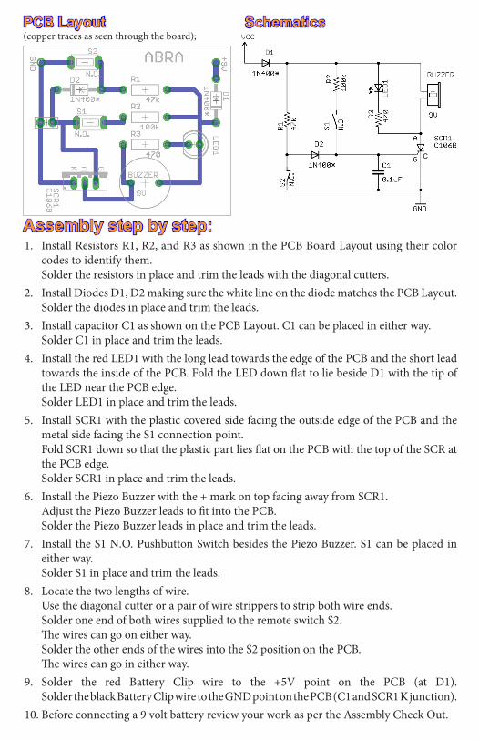
Assembly step by step:1. Install Resistors R1, R2, and R3 as shown in the PCB Board Layout using their color
codes to identify them. Solder the resistors in place and trim the leads with the diagonal cutters.2. Install Diodes D1, D2 making sure the white line on the diode matches the PCB Layout.
Solder the diodes in place and trim the leads.3. Install capacitor C1 as shown on the PCB Layout. C1 can be placed in either way. Solder C1 in place and trim the leads.4. Install the red LED1 with the long lead towards the edge of the PCB and the short lead
towards the inside of the PCB. Fold the LED down flat to lie beside D1 with the tip of the LED near the PCB edge.
Solder LED1 in place and trim the leads.5. Install SCR1 with the plastic covered side facing the outside edge of the PCB and the
metal side facing the S1 connection point. Fold SCR1 down so that the plastic part lies flat on the PCB with the top of the SCR at
the PCB edge. Solder SCR1 in place and trim the leads.6. Install the Piezo Buzzer with the + mark on top facing away from SCR1. Adjust the Piezo Buzzer leads to fit into the PCB. Solder the Piezo Buzzer leads in place and trim the leads.7. Install the S1 N.O. Pushbutton Switch besides the Piezo Buzzer. S1 can be placed in
either way. Solder S1 in place and trim the leads.8. Locate the two lengths of wire. Use the diagonal cutter or a pair of wire strippers to strip both wire ends. Solder one end of both wires supplied to the remote switch S2. The wires can go on either way. Solder the other ends of the wires into the S2 position on the PCB. The wires can go in either way.9. Solder the red Battery Clip wire to the +5V point on the PCB (at D1). Solder the black Battery Clip wire to the GND point on the PCB (C1 and SCR1 K junction).10. Before connecting a 9 volt battery review your work as per the Assembly Check Out.
PCB Layout Schematics(copper traces as seen through the board);
C
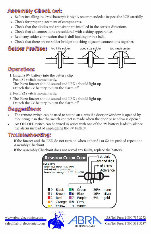
Assembly Check out: • Before installing the 9 volt battery it is highly recommended to inspect the PCB carefully.• Check for proper placement of components.• Check that the diodes and transistor are installed in the correct directions.• Check that all connections are soldered with a shiny appearance. • Redo any solder connection that is dull looking or in a ball.• Check that there are no solder bridges touching adjacent connections together.
Solder Profiles:
Operation: 1. Install a 9V battery into the battery clip. Push S1 switch momentarily. The Piezo Buzzer should sound and LED1 should light up. Detach the 9V battery to turn the alarm off.2. Push S2 switch momentarily.3. The Piezo Buzzer should sound and LED1 should light up. Detach the 9V battery to turn the alarm off.
Suggestions:• The remote switch can be used to sound an alarm if a door or window is opened by
mounting it so that the switch contact is made when the door or window is opened.• An ON-OFF switch can be wired in series with one of the 9V battery leads to silence
the alarm instead of unplugging the 9V battery.
Troubleshooting:- If the Buzzer and the LED do not turn on when either S1 or S2 are pushed repeat the Assembly Checkout. - If the Assembly Checkout does not reveal any faults, replace the battery.
www.abra-electronics.com U.STollFree:1-800-717-2272
[email protected] Can.TollFree:1-800-361-5237MADE IN CANADA