Embed Size (px)
Citation preview
This project allows you tocontrol the speed, direc-tion, and step size of aunipolar four-phase step-per motor. The controlleris capable of handling
motor winding currents of up to 1.25amps per phase and it operates from asingle supply voltage of 6-30 volts DC.
A unique feature of this project isthat the circuit can operate in eitherremote mode or stand-alone mode. Inthe stand-alone mode, an on-boardpulse generator and a four-position DIPswitch allows you to demonstrate all ofthe functions without any additionalconnections. This mode is perfect fordemonstrating basic stepper motor
control principles. The circuit evenhas LEDs that show the energizedphases for each step.
In remote mode, all motor func-tions can be interfaced to externallogic or a microcontroller. Thisallows the controller to be incorporatedinto a robot, an X-Y plotter, or anymotion control project you have inmind!
CIRCUIT DESCRIPTION
Refer to the schematic of the step-per driver shown in Figure 1. Power issupplied by a DC wall transformer orDC power supply at P1.
The voltage can be anything from6 to 30 volts, depending upon the rat-ing of the stepper motor. The steppermotor uses most of the current in thiscircuit, so it is powered directly fromthe transformer output through resis-tors R1 & R2.
These resistors limit the current tothe motor and allow the motor to beoperated with a power supply voltage
greater than the voltage rating of themotor for improved performance.
Stable voltage for the rest of thecircuit is obtained by regulating theinput voltage down to 5V with U4, aLM78L05 voltage regulator IC.Capacitors C7, C1, and C5 provideadditional voltage filtering. U1 is capa-ble of supplying up to 100 mA of cur-rent.
The heart of the stepper controlleris U1, a UCN5804B stepper-motortranslator/driver IC. It contains aCMOS logic section for the sequencinglogic and a high-voltage bipolar outputsection to directly drive a unipolar step-per motor. U1 can generate waveformsfor three different sequence modes: (1)
FULL-STEP with two phases ener-gized, (2) FULL-STEP WAVE and (3)HALF-STEP. The waveforms forthese three sequence modes areshown in Figure 5.
Diodes D1-4 are clamps to pre-vent damage to U1 if the outputsswing below ground when driving theinductive load of the motor.
Each of the LEDs L1-4 lightwhen the corresponding output goesLOW and are useful for observingthe output waveforms. Resistor R3provides current limiting to theLEDs.
Pins 9, 10, 14, and 15 of U1are control inputs for phase, half-step, direction, and output-enable.These signals are pulled-down to alogic LOW level by resistors R7-11.
The control signals go to bothReprinted from October 1998 Nuts & Volts Magazine. All rights reserved. No duplication permitted without permission from T & L Publications, Inc. 1
BUILD THISSTEPPERMOTOR
CONTROLLER
byDavidWilliams
If you’re interested in robotics, motion control,or just want to learn about stepper motors, thenyou should try building this versatile steppermotor controller.
Pin Assignments -
LM555NTimer IC
RESET
OUT
TRIG
GND
DISCH
CONT
1
2
3
4 5
6
7
8
THRESH
Vcc
Pin Assignments -
UCN5804BSTEPPER MOTOR
TRANSLATOR/DRIVER
10
9 ONE-PHASE
HALF-STEP
STEP INPUT
GND
OUT C
COM AC
GND
GND
OUT D
COM BD
OUT B
OUT ENABLE
GND
1
2
3
4
5
6
7
8
11
12
13
14
15
16
OUT A
DIRECTION
Vdd
Resistors (Except where noted, resistors are 5%, 1/4 Watt)R1,2 ....... 50 Ohm, 5 Watt R3 ........ 330 Ohm (Orange, Orange, Brown, Gold) R4 ........ 10 K Ohm (Brown, Black, Orange, Gold) R5 ........ 22 K Ohm (Red, Red, Orange, Gold)R6 ........ 220 K Ohm (Red, Red, Yellow, Gold)R7-12 ..... 100 K Ohm (Brown, Black, Yellow, Gold)R13 ....... 100 K Ohm Potentiometer CapacitorsC1-3 ......... 0.1 uF, Ceramic, marked: [104]C4-6 .......... 1.0 uF, 16V Tantalum or ElectrolyticC7 ........... 470 uF, 35V Electrolytic SemiconductorsU1 ........... UCN5804B, Stepper Controller ICU2,3 ......... LM555N, Timer IC U4 ........... LM78L05, 5 Volt DC Regulator (TO-92) D1-4.......... 1N4001 (or 1N4004), Rectifier Diode L1-4 ......... RED Light Emitting DiodeMiscellaneous ItemsJP1 — Wire Jumper, 0.4 inches long JP2 — Wire Jumper, 0.5 inches long JP3 — Wire Jumper, 0.6 inches long J1 — 3-pin Jumper Post & Shorting Blocks J2 — 2-pin Jumper Post & Shorting Blocks P1 — 2-pos Terminal Block P2 — 6-pos Terminal Block P3 — 7-pin Jumper Post S1-4 — 4-position DIP Switch S5 — Miniature Pushbutton Switch U1 — 16-Pin IC Socket U2,3 — 8-Pin IC Socket PCB — Etched Printed Circuit Board (STP0297)MOT — Unipolar (6-wire) Stepper MotorTXFMR — 12-14V DC, 500mA Wall Transformer or DC power supplyMisc: Hook-up Wire, Hardware, Solder, Etc.
The following items are available from: LNS Technologies, P.O. Box 67243, ScottsValley, CA 95067, Phone: (831) 768-9155.
STEPPER-KIT: Complete kit of parts for the Stepper Motor Controller including etchedand drilled printed circuit board, stepper motor, DC wall transformer, ICs, and all othercomponents listed above $39.00. UCN5804B: Stepper Motor Driver IC (U1) $5.00.STEPPER-PCB: PC Board for Stepper Controller Kit $10.00.
Please add $5.00 Shipping/Handling. California residents add 8% sales tax. MC/VISAorders accepted. No COD orders.
The UCN5804B IC is also available from: Alltronics, 2300 Zanker Rd., San Jose, CA 95131, (408) 934-9773. 931002: Stepper Motor Driver IC $4.50.
Parts ListFor TheStepperMotorController
FIGURE 4

connector P3 and the four-position DIPswitch (S1-4). Switches 1-4 allow formanual control of each function, oralternatively, connector P3 allows thefunctions to be controlled by externallogic or a microcontroller chip.
The UCN5804B requires anexternal pulse input on pin 11 toadvance the stepper motor. This signalcan be supplied by external logic viaconnector P3 or can be provided byU2 or U3. U2 and U3 are LM555Ntimer ICs and are used to provide sin-gle-step or continuous pulses to U1.
U2 is configured as an astableoscillator that delivers continuous puls-es. The pulse rate is controlled by
potentiometer R13 and capacitor C2.Jumper J2 connects C6 in parallel withC2 to give a LOW SPEED range. U3 isconfigured in a monostable mode toproduce a single pulse when S5 ispressed. Jumper J1 selects betweenthe single-step or continuous mode.
ASSEMBLY INSTRUCTIONS
The easiest way to build the step-per motor controller is to use an etchedcircuit board as shown in Figure 2. Ifyou don’t want to fabricate your ownboard, a pre-etched and drilled boardcan be purchased from the sourceshown in the parts list.
Locate all the components shownin the parts list and use Figure 3 todetermine component placement onthe PC board. Begin by using threepieces of solid wire for J1, J2, and J3.Next install and solder the four diodesin place, noting their polarity. Then
move on to the resistors and ceramiccapacitors.
When installing the 5-watt resis-tors R1 and R2, leave a small spacebetween the resistors and the PC boardto allow for air circulation. Be sure toobserve proper polarities wheninstalling the electrolytic and tantalum
capacitors and the voltage regulator.Note that it may be necessary to bendthe leads of the U4 to fit the PC board.
Now solder IC sockets for U1, U2,and U3 to the board. If you use theswitch specified in the parts list for S5,it can be soldered directly on the print-ed circuit board. Then install the fourLEDs as shown in Figure 3.
It is recommended that you usescrew-terminal connectors for P1 andP2. Potentiometer R13 can be eitherPC mount style or panel mount style.To use a panel mount potentiometer,cut three pieces of stranded wire toconnect R3 to the PC board. If youplan to use the controller in stand-
alone mode, solder a four-position DIPwitch for S1-4. You may omit the DIPswitch if you plan to use the P3 con-nector for remote interfacing.
Next, locate the UCN5804B inte-grated circuit (U1). Since U1 is aCMOS device, it can be easily dam-aged by static electricity. Take properanti-static precautions when handling
the chip. Refer againto Figure 3 beforeinstalling U1 to makesure of the proper ori-entation of pin 1,then press the ICfirmly into the 16-pinsocket. Repeat theprocedure with ICsU2 and U3.
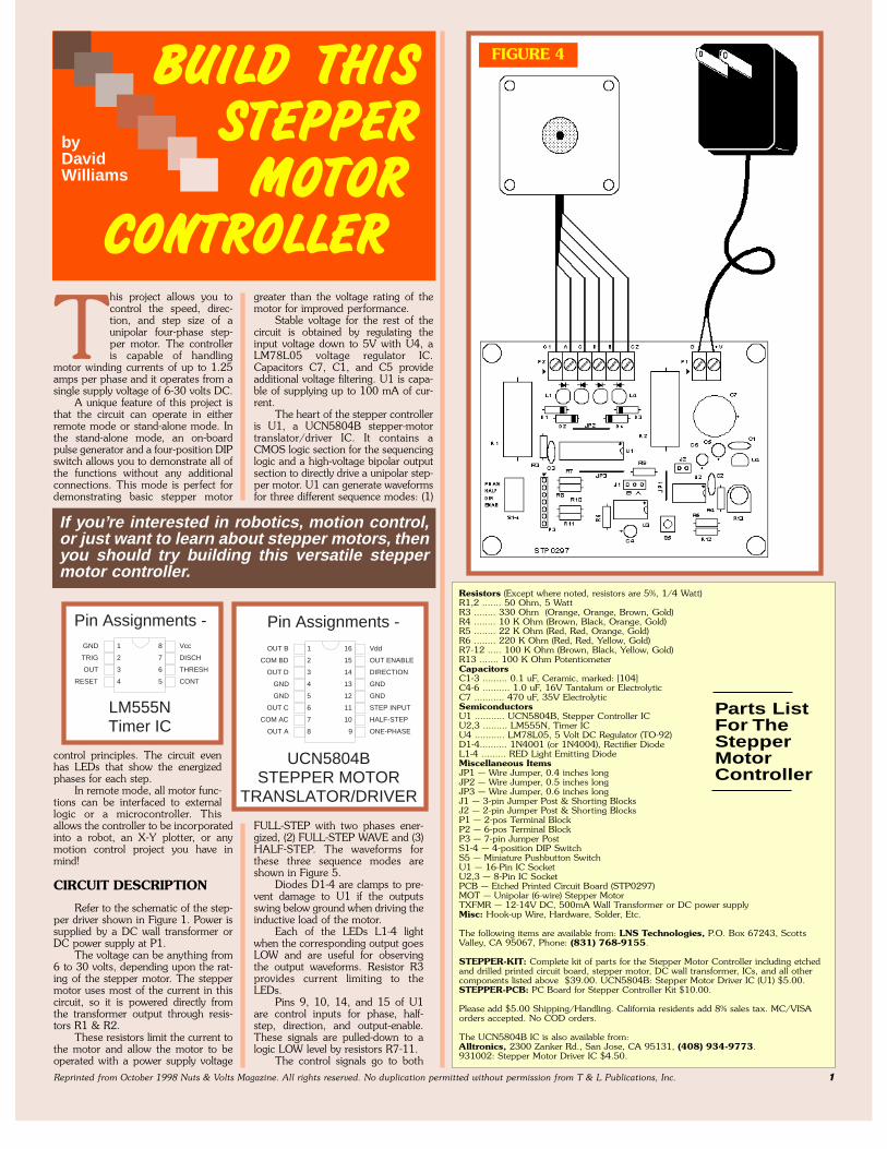
FINALASSEMBLY
Before continu-ing, clean the foil sideof the PC board withalcohol or fluxremover. Then referto Figure 4 for detailson connecting thestepper motor andDC power supply.Note that the wirecolors for the steppermotor shown inFigure 4 apply only tothe PF-42 motor thatis included in the pur-chased kit. If you usea different motor, youwill need to deter-mine the appropriatewire connections toP2. Also note that thecircuit is designed todrive six-wire UNIPO-
LAR motors only. Next, attach thewires from the DC power source to thePC board, observing the polarity showin Figure 4.
OPERATION
To run the stepper controller usingthe on-board oscillator, install jumperJ1 in the “A” position and leave J2open.
On the four-position DIP switch,set S1, S2, S3, and S4 all to the “OFF”position. Switch the DC power sourceON and the stepper motor should startto turn. The speed can be regulatedwith potentiometer R13. Installing
jumper J2 willswitch to a low-speed range. If you tryto drive a stepper motor too fast orwith too large of a load, it can stall (seethe note listed at the end of the article).
With the motor turning properly,you can switch S2, S3, and S4 tochange the direction, step size, orphasing (see Figure 6). Note that S1 is
Reprinted from October 1998 Nuts & Volts Magazine. All rights reserved. No duplication permitted without permission from T & L Publications, Inc. 2
+5V
+5V
8
1
BLACK
YELLOW
ORANGE
RED
DIRECTIONENABLE+5V
GNDSTEPHALFSTEP
9-24VDC
1
8
PHASE
B
A
BROWN
RED
SINGLE STEP
CONTINUOUS
P1
P2
1
2
1
2
3
4
5
6
R1
505W
R8
100K
R250 Ohm5W
D4
D3
D2
D1
C7
470 MFD
PF-42STEPPER MOTOR
R9
100K
R10
100K
R11
100K
U3
NE555
TR2
CV5
Q 3
DIS 7
THR 6
R
4
C4
1.0 MFD
+
R6
220K
L1
L2
L3
L4
R3
330
S1-4
SW DIP-4
1234
8765
R7
100K
S5
STEP
R12100K
C61.0 MFD
+
R4
10KJ2
LOWSPEED
R5 22K
U2
NE555
TR2
CV5
Q3
DIS7
THR6
R
4
R13100KSPEEDADJUST
U4 LM78L05
IN1 OUT 3
GND
2
U1
UCN5804
OUTB1KBD2OUTD3GND4GND5OUTC6KAC7OUTA8 PH 9
HS 10STEP 11GND 12GND 13DIR 14OE 15Vdd 16
J1
P3
EXTERNAL SIGNALS
1234567
C1
0.1MFD
C3
0.1MFD
C5
1.0MFD
C2
0.1 MFD
COM B-D
PHASE D
PHASE C
PHASE A
COM A-C
GND
+V
PHASE B
SINGLE
+ +
FIGURE 1
FIGURE 3FIGURE 2

the output enable and will stop themotor when the switch is in the “ON”position. To control the stepper func-tions remotely, set all of the DIPswitches to the “OFF” position andthen use P3 to connect the control sig-nals to an external microcontroller ortoggle switches.
To operate the stepper controllerin the single-step mode, install jumperJ1 in the “B” position. Each time youpress switch S5, the LN555 (U3) willproduce a single pulse and will causethe UCN5804 to advance the motorone sequence position. The motorsequence will still be determined by thesettings of S2, S3, and S4.
For single-step to work properly,you must release S5 before U3 com-pletes its output pulse or else theLM555 will automatically re-trigger.The single-step mode is a great educa-tional tool because you can actuallyobserve the various step sequences inthe LEDs (L1-4).
This controller is a robot builder’sdream come true! The kit also makes agreat educational project for demon-strating basic stepper motor control
principles. NV
Reprinted from October 1998 Nuts & Volts Magazine. All rights reserved. No duplication permitted without permission from T & L Publications, Inc. 3
S2-PIN 14FUNCTION
S1-PIN 15
LH
LH
REVERSE
FORWARD
DISABLED
ENABLEDOUTPUT
OUTPUT
S4-PIN 9FUNCTION
S3-PIN 10
L LH LL HH H
HALF-STEP
2-PHASEFULL-STEP
WAVE DRIVEFULL-STEP
INHIBITSTEP
NOTE:
All stepper motors exhibit aninverse speed-torque relation-
ship. As the stepping rate increas-es, the back EMF produced by themotor causes the current todecrease, which leads to adecrease in torque. If the steppingrate continues to increase, at somepoint the torque of the motor willdrop below the inertial load andthe motor will “STALL.” The speed-torque curve can be greatlyimproved by using a higher inputvoltage with series resistors (R1and R2). Higher input voltages willcontinue to improve the perfor-mance until practical power dissi-pation limits are reached or thevoltage/current ratings of theUCN5804B are exceeded.
FIGURE 6
FIGURE 5
Note:While preparing the reprint of this article in PDFformat, it was reduced to 81% of its original size, soit could be printed on 8½ x 11 paper.Therefore, ifyou desire to use the PCB pattern printed here,you should enlarge it to the correct size. (124%)
Also, the pricing and continued availability of kits orparts, by the listed sources, has not been verifiedand may have changed.