Embed Size (px)
Citation preview
Build Phase ■ 75
Build Phase
Overview
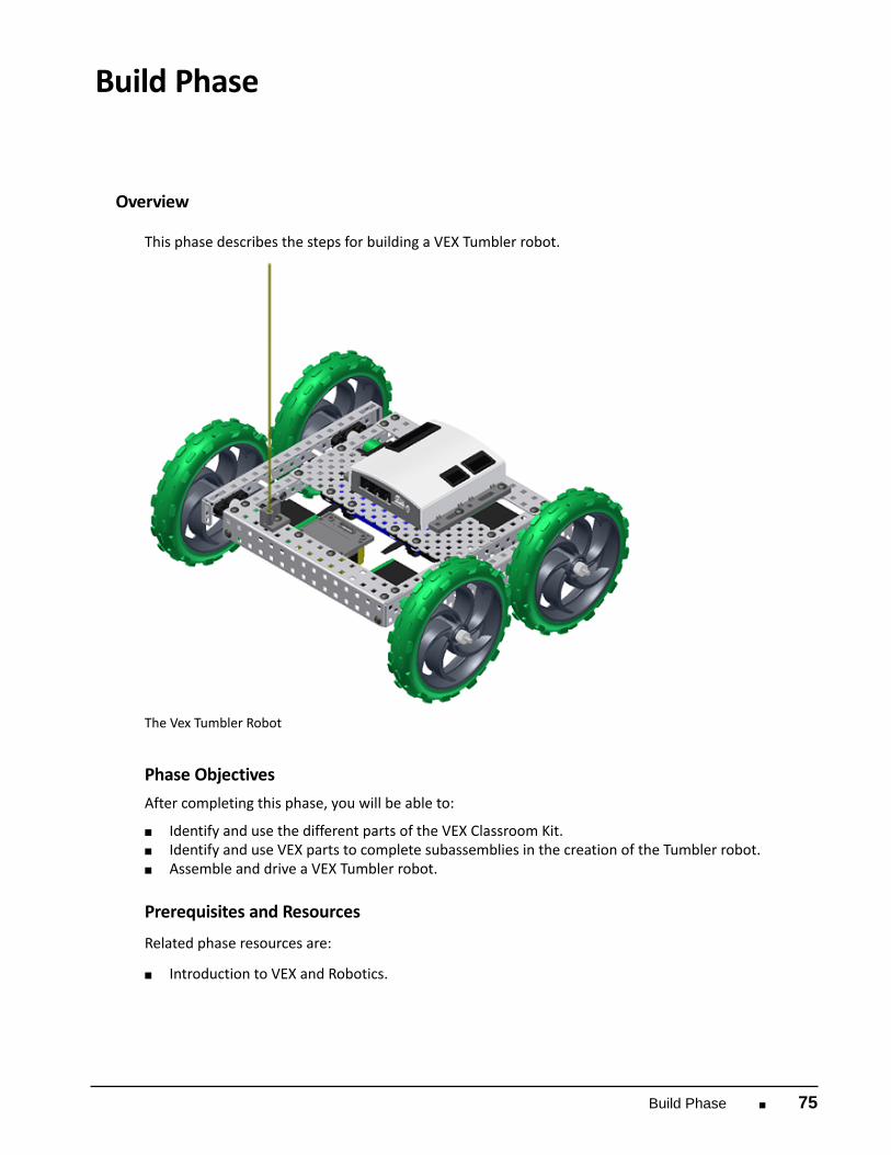
This phase describes the steps for building a VEX Tumbler robot.
The Vex Tumbler Robot
Phase Objectives
After completing this phase, you will be able to:
■ Identify and use the different parts of the VEX Classroom Kit. ■ Identify and use VEX parts to complete subassemblies in the creation of the Tumbler robot. ■ Assemble and drive a VEX Tumbler robot.
Prerequisites and Resources
Related phase resources are:
■ Introduction to VEX and Robotics.

76 ■ Autodesk's VEX Robotics Unit 1: Introduction to VEX and Robotics
Required Supplies and Software
The following supplies are used in this phase:
Supplies
VEX Classroom Lab Kit
Work surface
Small storage container for loose parts
VEX Parts
The following VEX parts are used in this phase:
Quantity
Part Number
Abbreviations
1 ANTENNA HOLDER AH
1 ANTENNA TUBE AT
1 7.2 VOLT RECHARGEABLE BATTERY BP
2 BATTERY-STRAP BST
4 BEAM-1000 B1
4 BEARING-FLAT BF
8 BEARING-RIVET BR
2 CHASSIS BUMPER, 15 HOLE A15
4 CHASSIS RAIL, 15 HOLE R15
1 JUMPER JMP
4 ROUGH TERRAIN WHEEL W5
1 MICROCONTROLLER VMC
25 NUT-832-KEPS NK

Build Phase ■ 77
Quantity
Part Number
Abbreviations
1 PLATE, 5x15 HOLE P15
1 RECEIVER RX75
8 SCREW-632-0250 SS2
24 SCREW-832-0250 S2
9 SCREW-832-0375 S3
4 SHAFT-3000 SQ3
8 SHAFT COLLAR COL
4 SPACER-THIN SP1
4 VEX MOTOR with CLUTCH MOT

78 ■ Autodesk's VEX Robotics Unit 1: Introduction to VEX and Robotics
Activity
Tumbler Right Side Drive
In this activity, you build a complete robot called Tumbler.
You start by building the right-side drive train.
1. The completed model is as shown: To complete the first step:■ Locate one Chassis Rail [R15].■ Fasten two Bearing Flats [BF] to the Chassis Rail using two Bearing Rivets [BR] for each
Bearing Flat.■ Fasten two 1" Beams [B1] to the Chassis Rail using using #8-32 x 1/4" screws [S2].

Build Phase ■ 79

80 ■ Autodesk's VEX Robotics Unit 1: Introduction to VEX and Robotics
2. To complete the next step:
■ Locate an additional Chassis Rail [R15] from the kit.■ Fasten two motors [MOT] to the Chassis Rail using two #6-32 x 1/4" screws [SS2] per
motor. Make sure the motors are oriented correctly.

Build Phase ■ 81
3. To complete the next step:
■ Orient the two assemblies and connect them by inserting #8-32 x 1/4" Screws [S2] intothe end of the Beams.
■ Insert a 3" Shaft [SQ3] into each motor, adding a Collar [COL] to the shaft as you insert itthrough the two rails.
■ When you have seated the shaft into the motor, slide the collar against the Bearing Flatand tighten. The collar prevents the shaft from coming out of the motor.
The completed model is as shown:

82 ■ Autodesk's VEX Robotics Unit 1: Introduction to VEX and Robotics
4. To complete the next step:
■ Slide a Thin Spacer [SP1] onto each shaft.■ Slide a Rough Terrain Wheel [W5] onto each shaft.■ Slide Shaft Collars [COL] up against the wheels and tighten.

Build Phase ■ 83
5. The right-side drive train is complete!

84 ■ Autodesk's VEX Robotics Unit 1: Introduction to VEX and Robotics
Assemble the Left Side Drive
You now build the left side of the drive train.
1. To complete the first step:■ Locate one Chassis Rail [R15].■ Fasten two Bearing Flats [BF] to the Chassis Rail using two Bearing Rivets [BR] for each
Bearing Flat.■ Fasten two 1" Beams [B1] to the Chassis Rail using using #8-32 x 1/4" screws [S2].
The completed model is as shown:

Build Phase ■ 85
2. To complete the next step:
■ Locate an additional Chassis Rail [R15] from the kit.■ Fasten two motors [MOT] to the Chassis Rail using two #6-32 x 1/4" screws [SS2] per
motor. Make sure the motors are oriented correctly.
The completed model is as shown:

86 ■ Autodesk's VEX Robotics Unit 1: Introduction to VEX and Robotics
3. To complete the next step:
■ Orient the two assemblies and connect them by inserting #8-32 x 1/4" Screws [S2] intothe end of the Beams.
■ Insert a 3" Shaft [SQ3] into each motor, adding a Collar [COL] to the shaft as you insert itthrough the two rails.
■ When you have seated the shaft into the motor, slide the collar against the Bearing Flatand tighten. The collar prevents the shaft from coming out of the motor.

Build Phase ■ 87
4. To complete the next step:
■ Slide a Thin Spacer [SP1] onto each shaft.■ Slide a Rough Terrain Wheel [W5] onto each shaft.■ Slide Shaft Collars [COL] up against the wheels and tighten.

88 ■ Autodesk's VEX Robotics Unit 1: Introduction to VEX and Robotics
5. The left side drive train is complete!
Build Phase ■ 89
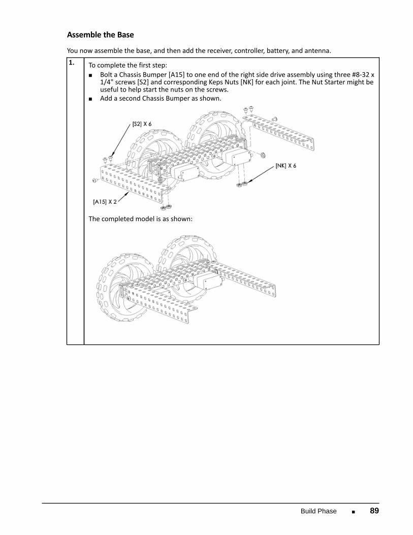
Assemble the Base
You now assemble the base, and then add the receiver, controller, battery, and antenna.
1. To complete the first step:■ Bolt a Chassis Bumper [A15] to one end of the right side drive assembly using three #8-32 x
1/4" screws [S2] and corresponding Keps Nuts [NK] for each joint. The Nut Starter might beuseful to help start the nuts on the screws.
■ Add a second Chassis Bumper as shown.
The completed model is as shown:
90 ■ Autodesk's VEX Robotics Unit 1: Introduction to VEX and Robotics
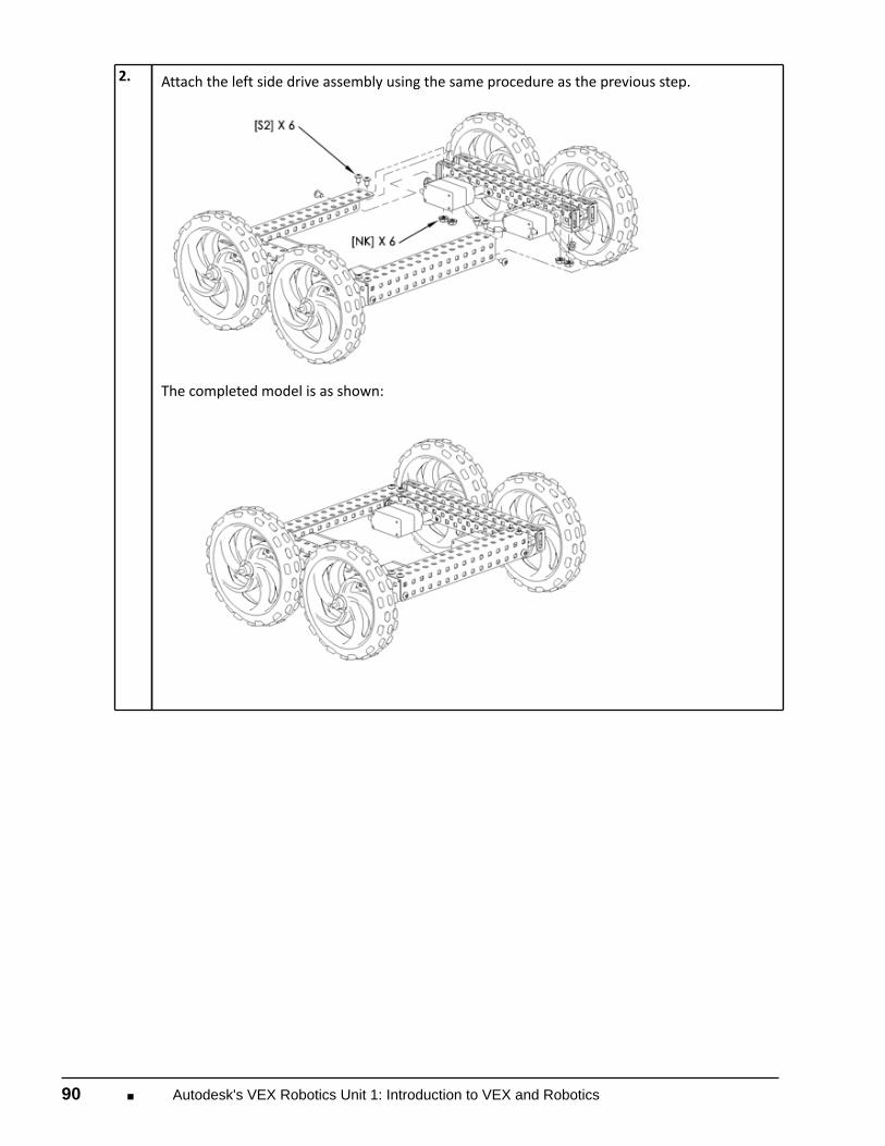
2. Attach the left side drive assembly using the same procedure as the previous step.
The completed model is as shown:

Build Phase ■ 91
3. Attach a Plate 5x15 [P15] to the top of the chassis using #8-32 x 1/4" screws [S2] and Keps
Nuts [NK].
The completed model is as shown:

92 ■ Autodesk's VEX Robotics Unit 1: Introduction to VEX and Robotics
4. Attach the Receiver Module [RX75] to the underside of the chassis using two #8-32 x 3/8"
screws [S3] and Keps Nuts [NK].

Build Phase ■ 93
5. The completed model is as shown:

94 ■ Autodesk's VEX Robotics Unit 1: Introduction to VEX and Robotics
6. Attach the Microcontroller [VMC] to the top of the chassis using two #8-32 x 3/8" screws [S3]
and Keps Nuts [NK].

Build Phase ■ 95
7. The completed model is as shown:

96 ■ Autodesk's VEX Robotics Unit 1: Introduction to VEX and Robotics
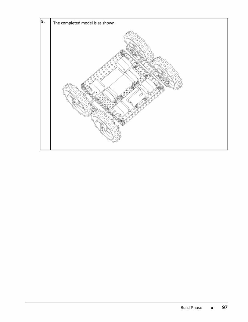
8. To complete the next step:
■ Attach two Battery Straps [BST] to the underside of the chassis using two #8-32 x 3/8"screws [S3] and Keps Nuts [NK] per strap.
■ Attach the 7.2 Volt Robot Battery [BP].
Build Phase ■ 97
9. The completed model is as shown:

98 ■ Autodesk's VEX Robotics Unit 1: Introduction to VEX and Robotics
10. To complete the next step:
■ Attach the Antenna Holder [AH] to the top of the chassis using one #8-32 x 3/8" screw [S3]and Keps Nut [NK].
■ Slide the antenna wire into the Antenna Tube [AT].■ Insert the Antenna Tube into the Antenna Holder.

Build Phase ■ 99
11. The completed model is as shown:
100 ■ Autodesk's VEX Robotics Unit 1: Introduction to VEX and Robotics
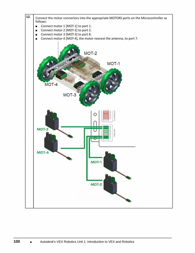
12. Connect the motor connectors into the appropriate MOTORS ports on the Microcontroller as
follows:■ Connect motor 1 [MOT-1] to port 1.■ Connect motor 2 [MOT-2] to port 2.■ Connect motor 3 [MOT-3] to port 8.■ Connect motor 4 [MOT-4], the motor nearest the antenna, to port 7.

Build Phase ■ 101
13. Insert a jumper into ANALOG/DIGITAL port 14 on the Microcontroller.
14. To complete the next step:
■ Connect the Receiver Module to port Rx1 on the microcontroller.■ Connect the Battery to the power port.

102 ■ Autodesk's VEX Robotics Unit 1: Introduction to VEX and Robotics
15. Your Tumbler is ready to roll!
Note: Electrical connections are not shown.

Build Phase ■ 103
Configure the Transmitter
You now configure the Transmitter to reverse the directional controls on channel 1. See the VEXInventor's Guide for detailed information on configuring the transmitter.
1. Turn on the Transmitter.
2. Check the voltage. If the voltage is less than 8.9 volts, recharge the batteries in the transmitter.
3. Press and hold the MODE and SELECT buttons simultaneously until the CONFIG menu is
displayed.

104 ■ Autodesk's VEX Robotics Unit 1: Introduction to VEX and Robotics
4. Press the MODE button once to display the REVERSE menu.
5. Press the DATA INPUT minus key once. The arrow should display next to REV (below CH on the
display).
6. Press and hold the MODE and SELECT buttons simultaneously until the voltage is displayed.
7. Turn on the Microcontroller and go for a drive!

Amaze Phase ■ 105
Amaze Phase
Overview
In this phase, students test their first VEX robot, Tumbler.
Phase Objectives
After completing this phase, you will be able to:
■ Test and demonstrate a VEX robot. ■ Identify the basic components of a VEX robot.
Prerequisites and Resources
Before starting this phase, you must have:
■ Completed all sections in the Unit 1: Introduction to VEX and Robotics up to the Amaze phase.
Required Supplies and Software
The following supplies are used in this phase:
Supplies
One assembled Tumbler robot
Notebook and pen
Two obstacles. This can be any small object in your class.
10' x 4' of open space against a wall.

106 ■ Autodesk's VEX Robotics Unit 1: Introduction to VEX and Robotics
Evaluation
Tumbler Challenge
In this challenge, you set up a basic obstacle course to test drive the Tumbler. You learn to drive a VEXrobot, while discovering some of the neat features that Tumbler showcases.
Challenge Instructions
1. Choose any two “obstacles” available to you in your classroom. These obstacles act as pylons forthe robot to navigate around.
2.
Place the two obstacles approximately 4' apart. See the following figure.
3. Place Tumbler beside the obstacle furthest from the wall. See the previous figure. 4. Turn Tumbler and its transmitter on. 5. Using the joysticks, have Tumbler drive the path shown in Figure 1. 6. When Tumbler approaches the wall, drive directly into it and cause Tumbler to flip over. 7. Follow the same path back to your starting position. 8. If time permits, experiment with Tumbler and drive it around your classroom.

Amaze Phase ■ 107
Engineering Notebook
In your engineering notebook, record a journal entry describing your experiences with the Tumblerrobot. Now that you have gotten a taste of the VEX Robotics Design System, brainstorm a list of robotsyou would like to create.
Presentation■ Prepare a short presentation for your class describing your favorite and most challenging parts of
Unit 1: Introduction to VEX and Robotics.■ Prepare a short presentation describing some ideas of VEX robots you would like to build.


![ijh dlZo Mfguc]hjh^](https://img.pdfslide.us/doc/110x75/6178408b2d304375647d2cf7/ijh-dlzo-mfguchjh.jpg)