Embed Size (px)
Citation preview
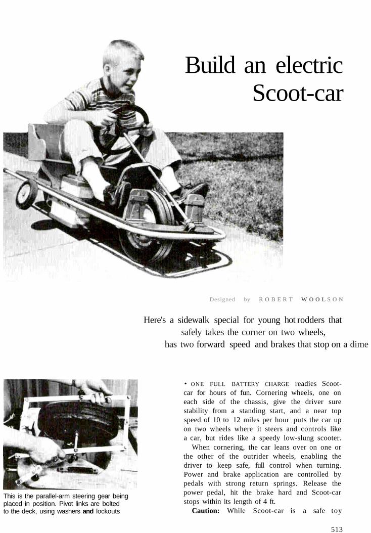
Build an electricScoot-car
Designed by R O B E R T W O O L S O N
Here's a sidewalk special for young hot rodders thatsafely takes the corner on two wheels,
has two forward speed and brakes that stop on a dime
This is the parallel-arm steering gear beingplaced in position. Pivot links are boltedto the deck, using washers and lockouts
• ONE FULL BATTERY CHARGE readies Scoot-car for hours of fun. Cornering wheels, one oneach side of the chassis, give the driver surestability from a standing start, and a near topspeed of 10 to 12 miles per hour puts the car upon two wheels where it steers and controls likea car, but rides like a speedy low-slung scooter.
When cornering, the car leans over on one orthe other of the outrider wheels, enabling thedriver to keep safe, full control when turning.Power and brake application are controlled bypedals with strong return springs. Release thepower pedal, hit the brake hard and Scoot-carstops within its length of 4 ft.
Caution: While Scoot-car is a safe toy
513
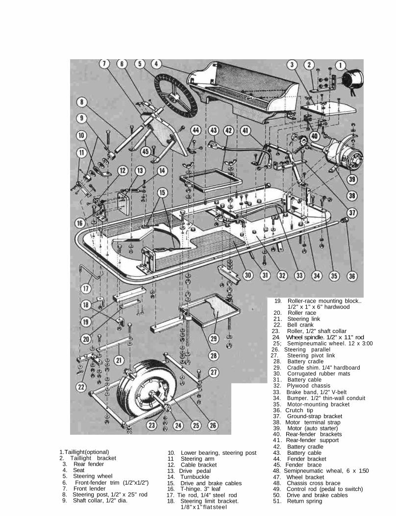
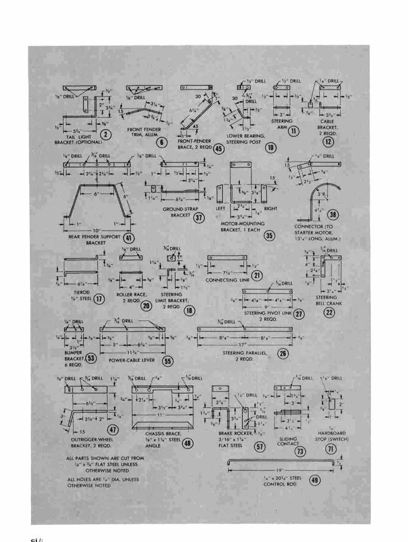
1. Taillight (optional)2. Taillight bracket3. Rear fender4. Seat5. Steering wheel6. Front-fender trim (1/2"x1/2")7. Front lender8. Steering post, 1/2" x 25" rod9. Shaft collar, 1/2" dia.
10. Lower bearing, steering post11 Steering arm12. Cable bracket13. Drive pedal14. Turnbuckle15. Drive and brake cables16. T-hinge. 3" leaf17. Tie rod, 1/4" steel rod18. Steering limit bracket.
1/8" x 1" flat steel
19. Roller-race mounting block..1/2" x 1" x 6" hardwood
20. Roller race21. Steering link22. Bell crank
23. Roller, 1/2" shaft collar24: Wheel spindle. 1/2" x 11" rod25; Semipneumalic wheel. 12 x 3:00
26. Steering parallel27. Steering pivot link28. Battery cradle29. Cradle shim. 1/4" hardboard30. Corrugated rubber mats31 . Battery cable32. Plywood chassis33. Brake band, 1/2" V-belt34. Bumper. 1/2" thin-wall conduit35. Motor-mounting bracket36. Crutch tip37. Ground-strap bracket38. Motor terminal strap39. Motor (auto starter)40. Rear-fender brackets41. Rear-fender support42. Battery cradle43. Battery cable44. Fender bracket45. Fender brace48. Semipneumatic wheal, 6 x 1:5047. Wheel bracket48. Chassis cross brace49. Control rod (pedal to switch)50. Drive and brake cables51. Return spring
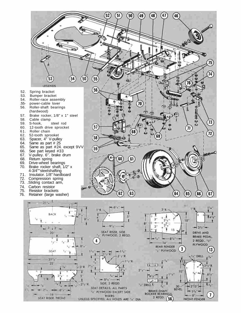
52. Spring bracket53. Bumper bracket54. Roller-race assembly.55- power-cable lover56. Roller-shaft bearings
(hardwood)57. Brake rocker, 1/8" x 1" steel58. Cable clamp59. S-hook, steel rod60. 12-tooth drive sprocket61 . Roller chain62. 52-tooth sprooket63. Spacer, 4" V-pulley64. Same as part # 2565. Same as part # 24. except 9VV66. See part keyed #3367. V-pulley. 6". brake drum68. Return spring69. Drive-wheel bearings70. Brake rocker shaft, 1/2" x
4-3/4"" steel shafting71. Insulator. 1/8" hardboard72. Compression spring73. .Sliding contact arm,74. Carbon resistor75. Resistor brackets76. Retainer (large washer)
ci /:
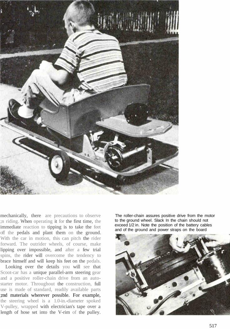
mechanically, there are precautions to observe;n riding. When operating it for the first time, theimmediate reaction to tipping is to take the feetoff the pedals and plant them on the ground.With the car in motion, this can pitch the riderforward. The outrider wheels, of course, makelipping over impossible, and after a few trialspins, the rider will overcome the tendency tobrace himself and will keep his feet on the pedals.
Looking over the details you will see thatScoot-car has a unique parallel-arm steering gearand a positive roller-chain drive from an auto-starter motor. Throughout the construction, fulluse is made of standard, readily available parts;md materials wherever possible. For example,the steering wheel is a 1.0-in.-diameter spokedV-pulley, wrapped with electrician's tape over alength of hose set into the V-rim of the pulley.
The roller-chain assures positive drive from the motorto the ground wheel. Slack In the chain should notexceed 1/2 in. Note the position of the battery cablesand of the ground and power straps on the board
517
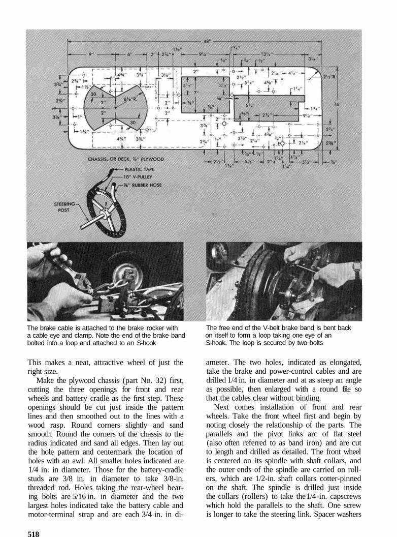
The brake cable is attached to the brake rocker witha cable eye and clamp. Note the end of the brake bandbolted into a loop and attached to an S-hook
This makes a neat, attractive wheel of just theright size.
Make the plywood chassis (part No. 32) first,cutting the three openings for front and rearwheels and battery cradle as the first step. Theseopenings should be cut just inside the patternlines and then smoothed out to the lines with awood rasp. Round corners slightly and sandsmooth. Round the corners of the chassis to theradius indicated and sand all edges. Then lay outthe hole pattern and centermark the location ofholes with an awl. All smaller holes indicated are1/4 in. in diameter. Those for the battery-cradlestuds are 3/8 in. in diameter to take 3/8-in.threaded rod. Holes taking the rear-wheel bear-ing bolts are 5/16 in. in diameter and the twolargest holes indicated take the battery cable andmotor-terminal strap and are each 3/4 in. in di-
The free end of the V-belt brake band is bent backon itself to form a loop taking one eye of anS-hook. The loop is secured by two bolts
ameter. The two holes, indicated as elongated,take the brake and power-control cables and aredrilled 1/4 in. in diameter and at as steep an angleas possible, then enlarged with a round file sothat the cables clear without binding.
Next comes installation of front and rearwheels. Take the front wheel first and begin bynoting closely the relationship of the parts. Theparallels and the pivot links arc of flat steel(also often referred to as band iron) and are cutto length and drilled as detailed. The front wheelis centered on its spindle with shaft collars, andthe outer ends of the spindle are carried on roll-ers, which are 1/2-in. shaft collars cotter-pinnedon the shaft. The spindle is drilled just insidethe collars (rollers) to take the 1/4 -in. capscrewswhich hold the parallels to the shaft. One screwis longer to take the steering link. Spacer washers
518
are placed between the joining parts and allscrews carry additional washers and locknuts topermit free movement. In the assembly, therollers on the ends of the wheel spindle ride onraces made as shown. Each consists of a mount-ing block of hardwood and a facing of flat steel,and the two units are attached to the undersideof the deck with wood screws. The pivot links arebolted to the underside of the deck and the steer-ing, or connecting, link attaches to the bell crank.The latter is bolted to the underside of the chassisand the free arm takes the lower end of the tierod when assembled. The upper end of the tierod is attached to the steering arm on the lowerend of the steering post. The steering arm is riv-eted to a shaft collar which provides a hub anda means of attaching to the steering post.
rear wheel attached next
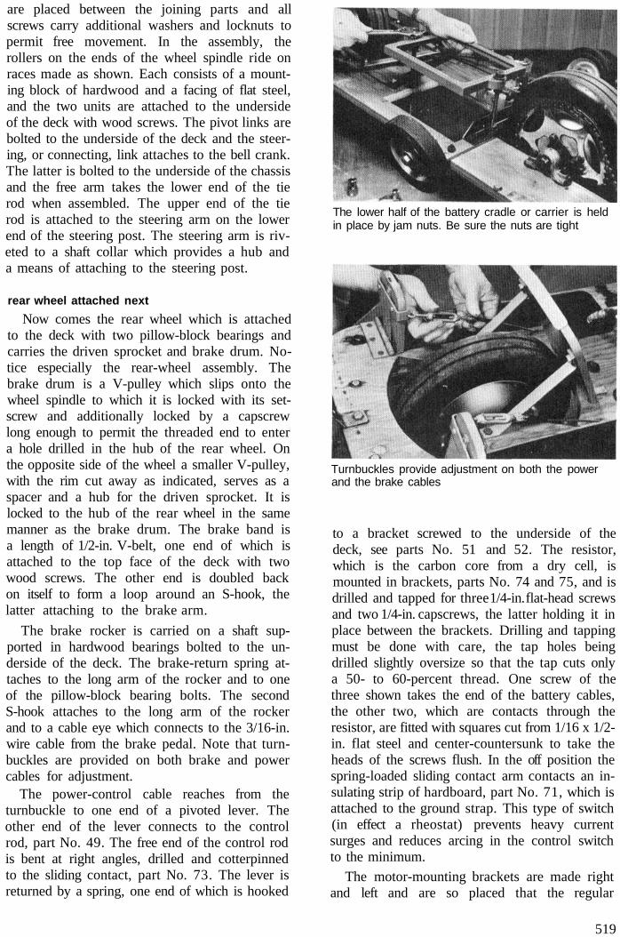
Now comes the rear wheel which is attachedto the deck with two pillow-block bearings andcarries the driven sprocket and brake drum. No-tice especially the rear-wheel assembly. Thebrake drum is a V-pulley which slips onto thewheel spindle to which it is locked with its set-screw and additionally locked by a capscrewlong enough to permit the threaded end to entera hole drilled in the hub of the rear wheel. Onthe opposite side of the wheel a smaller V-pulley,with the rim cut away as indicated, serves as aspacer and a hub for the driven sprocket. It islocked to the hub of the rear wheel in the samemanner as the brake drum. The brake band isa length of 1/2-in. V-belt, one end of which isattached to the top face of the deck with twowood screws. The other end is doubled backon itself to form a loop around an S-hook, thelatter attaching to the brake arm.
The brake rocker is carried on a shaft sup-ported in hardwood bearings bolted to the un-derside of the deck. The brake-return spring at-taches to the long arm of the rocker and to oneof the pillow-block bearing bolts. The secondS-hook attaches to the long arm of the rockerand to a cable eye which connects to the 3/16-in.wire cable from the brake pedal. Note that turn-buckles are provided on both brake and powercables for adjustment.
The power-control cable reaches from theturnbuckle to one end of a pivoted lever. Theother end of the lever connects to the controlrod, part No. 49. The free end of the control rodis bent at right angles, drilled and cotterpinnedto the sliding contact, part No. 73. The lever isreturned by a spring, one end of which is hooked
The lower half of the battery cradle or carrier is heldin place by jam nuts. Be sure the nuts are tight
Turnbuckles provide adjustment on both the powerand the brake cables
to a bracket screwed to the underside of thedeck, see parts No. 51 and 52. The resistor,which is the carbon core from a dry cell, ismounted in brackets, parts No. 74 and 75, and isdrilled and tapped for three 1/4-in. flat-head screwsand two 1/4-in. capscrews, the latter holding it inplace between the brackets. Drilling and tappingmust be done with care, the tap holes beingdrilled slightly oversize so that the tap cuts onlya 50- to 60-percent thread. One screw of thethree shown takes the end of the battery cables,the other two, which are contacts through theresistor, are fitted with squares cut from 1/16 x 1/2-in. flat steel and center-countersunk to take theheads of the screws flush. In the off position thespring-loaded sliding contact arm contacts an in-sulating strip of hardboard, part No. 71, which isattached to the ground strap. This type of switch(in effect a rheostat) prevents heavy currentsurges and reduces arcing in the control switchto the minimum.
The motor-mounting brackets are made rightand left and are so placed that the regular
519
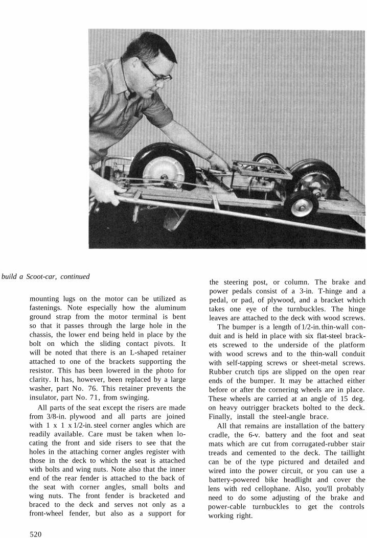
build a Scoot-car, continued
mounting lugs on the motor can be utilized asfastenings. Note especially how the aluminumground strap from the motor terminal is bentso that it passes through the large hole in thechassis, the lower end being held in place by thebolt on which the sliding contact pivots. Itwill be noted that there is an L-shaped retainerattached to one of the brackets supporting theresistor. This has been lowered in the photo forclarity. It has, however, been replaced by a largewasher, part No. 76. This retainer prevents theinsulator, part No. 71, from swinging.
All parts of the seat except the risers are madefrom 3/8-in. plywood and all parts are joinedwith 1 x 1 x 1/2-in. steel corner angles which arereadily available. Care must be taken when lo-cating the front and side risers to see that theholes in the attaching corner angles register withthose in the deck to which the seat is attachedwith bolts and wing nuts. Note also that the innerend of the rear fender is attached to the back ofthe seat with corner angles, small bolts andwing nuts. The front fender is bracketed andbraced to the deck and serves not only as afront-wheel fender, but also as a support for
the steering post, or column. The brake andpower pedals consist of a 3-in. T-hinge and apedal, or pad, of plywood, and a bracket whichtakes one eye of the turnbuckles. The hingeleaves are attached to the deck with wood screws.
The bumper is a length of 1/2-in. thin-wall con-duit and is held in place with six flat-steel brack-ets screwed to the underside of the platformwith wood screws and to the thin-wall conduitwith self-tapping screws or sheet-metal screws.Rubber crutch tips are slipped on the open rearends of the bumper. It may be attached eitherbefore or after the cornering wheels are in place.These wheels are carried at an angle of 15 deg.on heavy outrigger brackets bolted to the deck.Finally, install the steel-angle brace.
All that remains are installation of the batterycradle, the 6-v. battery and the foot and seatmats which are cut from corrugated-rubber stairtreads and cemented to the deck. The taillightcan be of the type pictured and detailed andwired into the power circuit, or you can use abattery-powered bike headlight and cover thelens with red cellophane. Also, you'll probablyneed to do some adjusting of the brake andpower-cable turnbuckles to get the controlsworking right.
520


![Untitled-1 [] · 740,000 Right To Use Additional Car Parking Charges: o Premium Covered Car Parking = INR 400,000 o Open Car Parking = INR 300,000 o Combined Car Parking = INR 200,000](https://img.pdfslide.us/doc/110x75/5ec23107d922333dc921e4cc/untitled-1-740000-right-to-use-additional-car-parking-charges-o-premium-covered.jpg)