Embed Size (px)
Citation preview
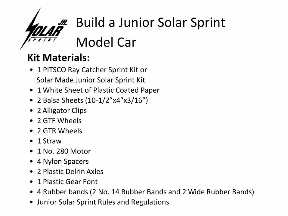
Build a Junior Solar Sprint
Model Car Kit Materials: • 1 PITSCO Ray Catcher Sprint Kit or
Solar Made Junior Solar Sprint Kit
• 1 White Sheet of Plastic Coated Paper
• 2 Balsa Sheets (10-1/2”x4”x3/16”)
• 2 Alligator Clips
• 2 GTF Wheels
• 2 GTR Wheels
• 1 Straw
• 1 No. 280 Motor
• 4 Nylon Spacers
• 2 Plastic Delrin Axles
• 1 Plastic Gear Font
• 4 Rubber bands (2 No. 14 Rubber Bands and 2 Wide Rubber Bands)
• Junior Solar Sprint Rules and Regulations
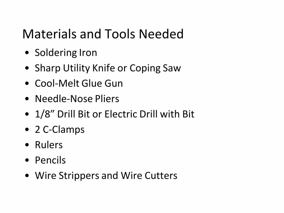
Materials and Tools Needed
• Soldering Iron
• Sharp Utility Knife or Coping Saw
• Cool-Melt Glue Gun
• Needle-Nose Pliers
• 1/8” Drill Bit or Electric Drill with Bit
• 2 C-Clamps
• Rulers
• Pencils
• Wire Strippers and Wire Cutters
Safety Precautions
• Instruct students in the proper use and care of sharp utility knives and coping saws. If there are safety concerns, use coping saws, not utility knives.
• Cover safety precautions for the use of electrical equipment such as glue guns and soldering irons.
• Caution students not to touch the metal top of the cool-melt glue gun and to keep the glue off their skin.
• The voltage produced by the solar panel and batteries are entirely SAFE for student use.
• Properly dispose of batteries.
• Before inserting wheels and gears onto axles, students need to insert a 1/8” drill bit through the holes of the wheels and gears for easy assembly. They should not “drill” the wheels and gear, but merely ream the hole slightly. If the fit is still too tight, either ream the hole again or use sandpaper to bring the diameter of the axle shaft to a good firm fit.
• Never force the wheels and gears onto the axles.
Making the Chassis
Lin
e A
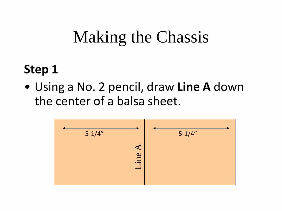
Step 1
• Using a No. 2 pencil, draw Line A down the center of a balsa sheet.
5-1/4” 5-1/4”
Making the Chassis
Lin
e B
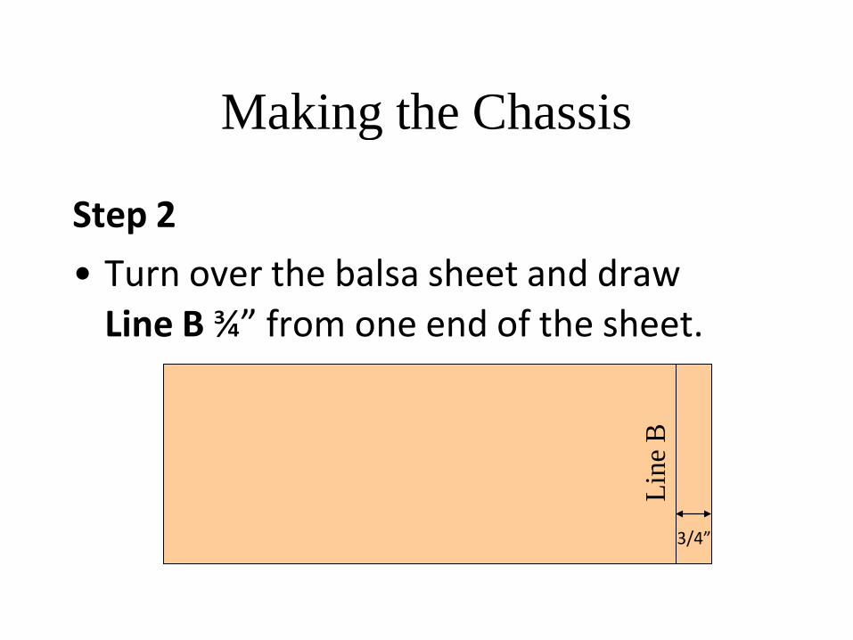
Step 2
• Turn over the balsa sheet and draw
Line B ¾” from one end of the sheet.
3/4”
Making the Chassis
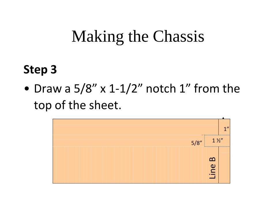
Step 3
• Draw a 5/8” x 1-1/2” notch 1” from the
top of the sheet.
1”
5/8” 1 ½”
Lin
e B
Making the Chassis
Lin
e C
Lin
e B
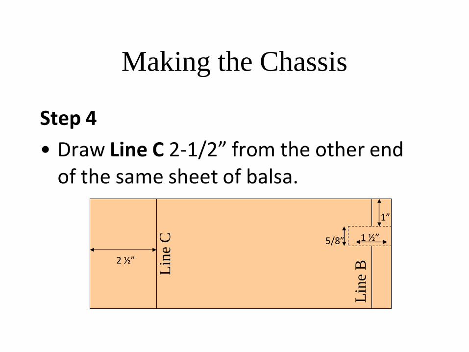
Step 4
• Draw Line C 2-1/2” from the other end of the same sheet of balsa.
2 ½”
5/8”
1”
1 ½”
Making the Chassis
1 ½”
Lin
e C
Lin
e B
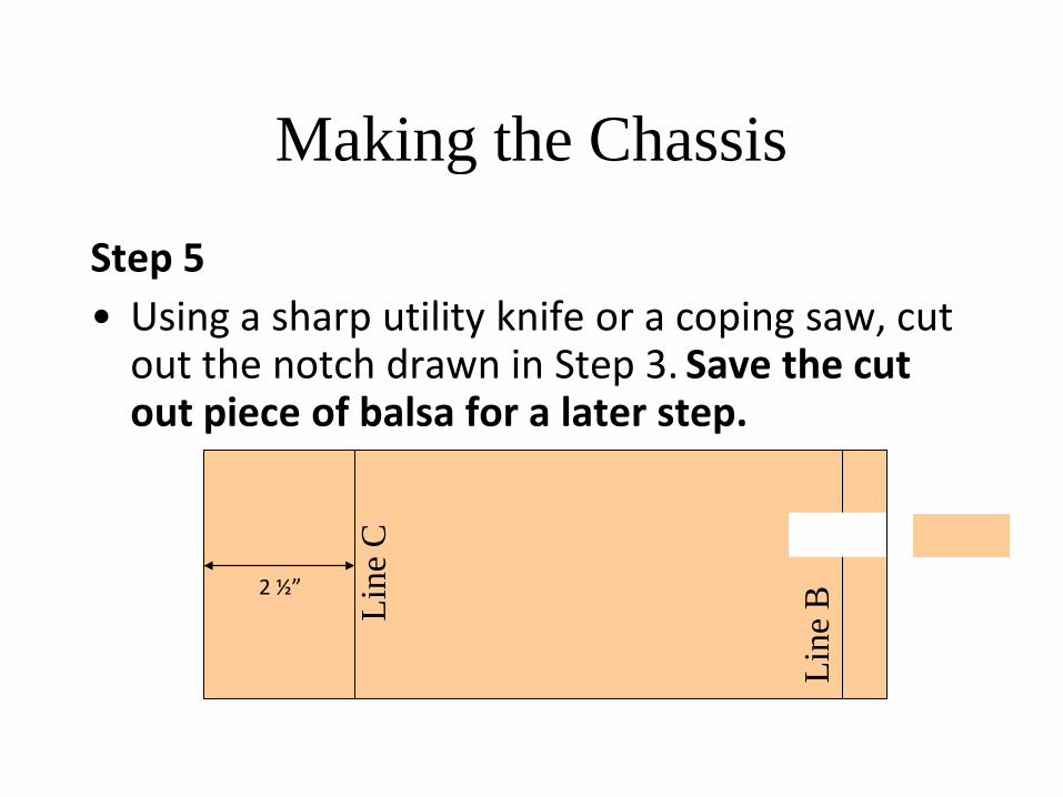
Step 5
• Using a sharp utility knife or a coping saw, cut out the notch drawn in Step 3. Save the cut out piece of balsa for a later step.
2 ½”
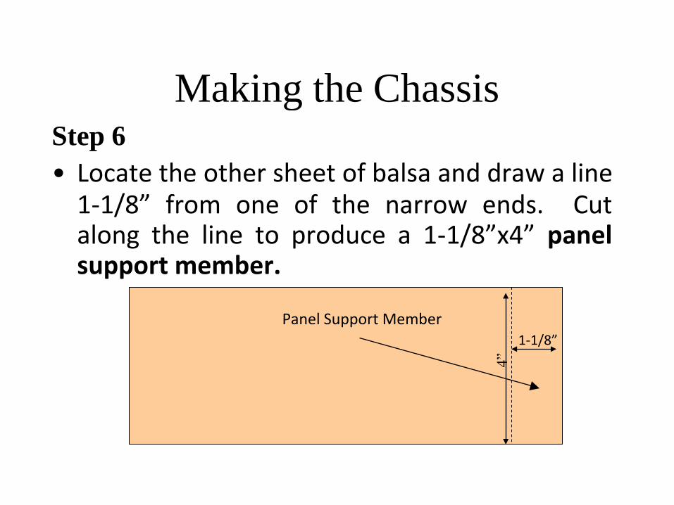
Making the Chassis Step 6
4”
• Locate the other sheet of balsa and draw a line 1-1/8” from one of the narrow ends. Cut along the line to produce a 1-1/8”x4” panel support member.
Panel Support Member
1-1/8”
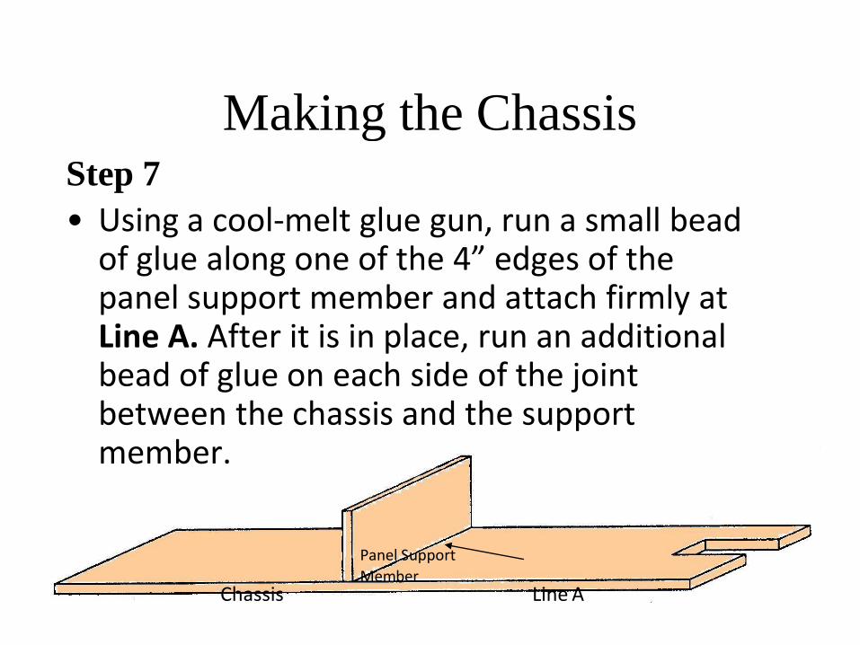
Making the Chassis Step 7
• Using a cool-melt glue gun, run a small bead of glue along one of the 4” edges of the panel support member and attach firmly at Line A. After it is in place, run an additional bead of glue on each side of the joint between the chassis and the support member.
Chassis
Panel Support
Member
Line A
Wheels, Gears, and Axles
Note:
Installing wheels and gears on axles can be difficult. Be careful not to bend the Delrin axle.
To ease the process, insert a 1/8” drill bit through the holes. The gears and wheels should fit snugly to the axle and provide power to the wheels.
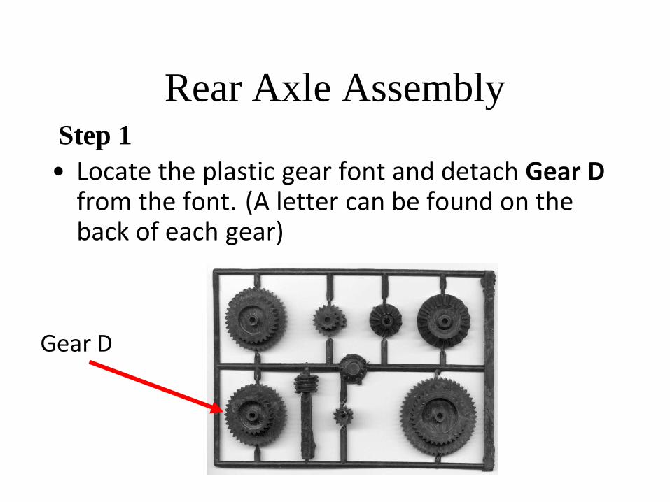
Rear Axle Assembly Step 1
• Locate the plastic gear font and detach Gear D from the font. (A letter can be found on the back of each gear)
Gear D
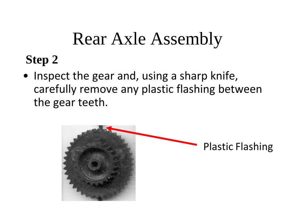
Rear Axle Assembly Step 2
• Inspect the gear and, using a sharp knife, carefully remove any plastic flashing between the gear teeth.
Plastic Flashing
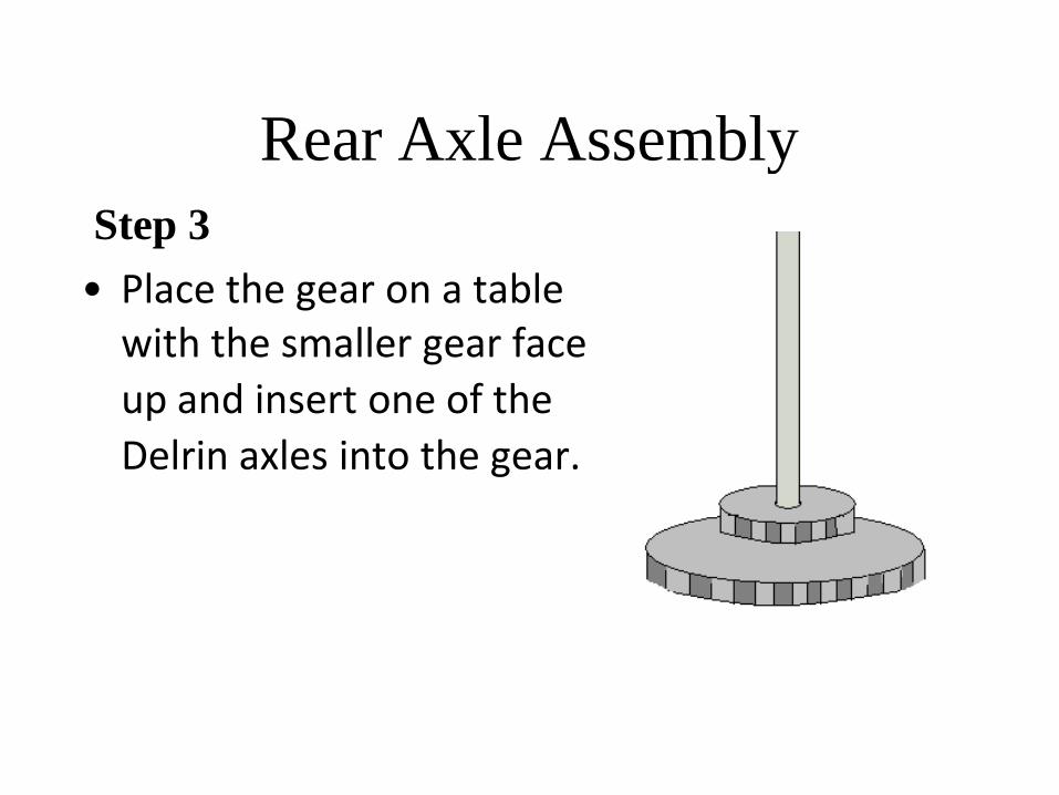
Rear Axle Assembly
Step 3
• Place the gear on a table with the smaller gear face
up and insert one of the
Delrin axles into the gear.
Rear Axle Assembly
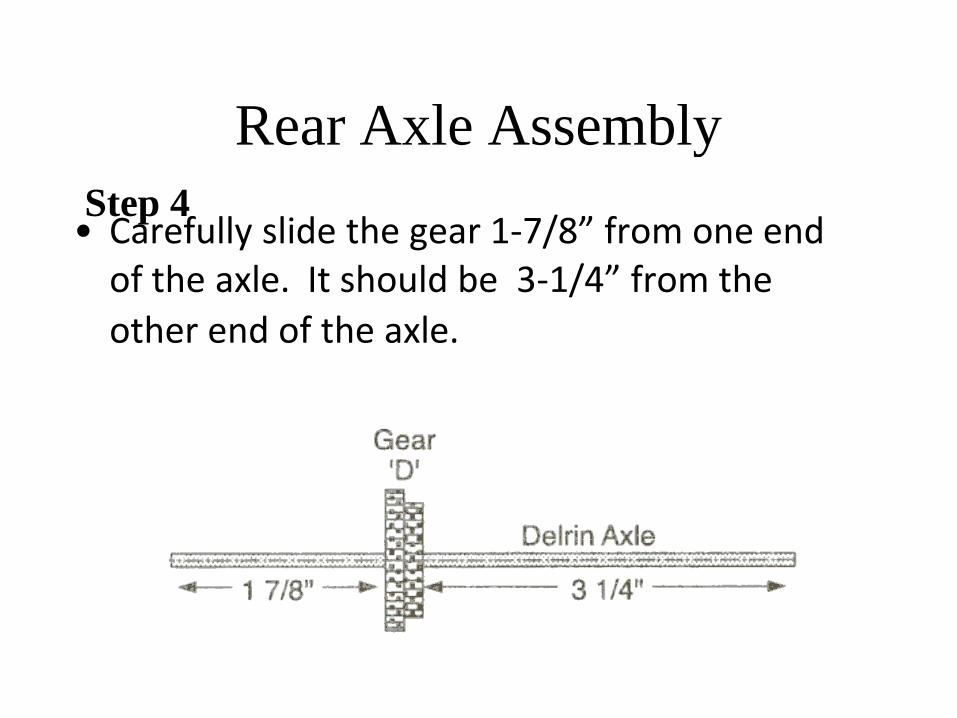
Step 4
• Carefully slide the gear 1-7/8” from one end of the axle. It should be 3-1/4” from the
other end of the axle.
Rear Axle Assembly
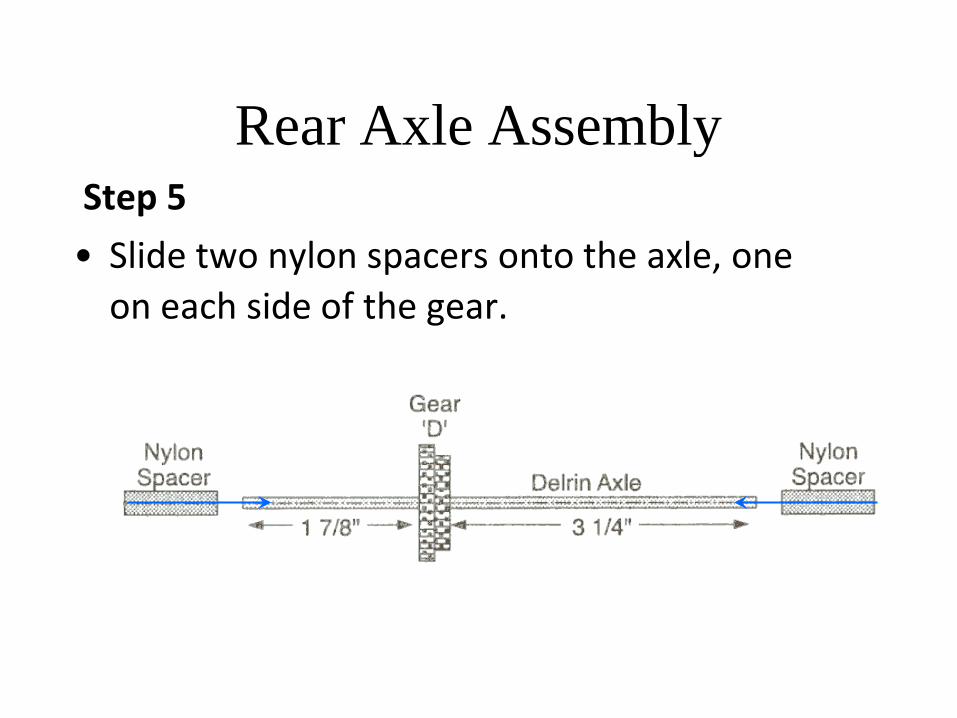
Step 5
• Slide two nylon spacers onto the axle, one
on each side of the gear.
Rear Axle Assembly Step 6
• Place one of the wide plastic wheels flat on a table. Keeping the spacers in place, insert one end of the axle into the wheel. Slide the axle into the wheel until it is flush with the opposite side of the wheel.
Rear Axle Assembly Step 7
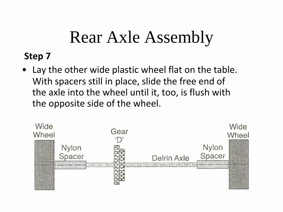
Rear Axle Assembly
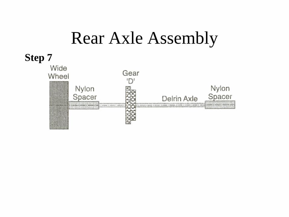
Step 7
• Lay the other wide plastic wheel flat on the table. With spacers still in place, slide the free end of the axle into the wheel until it, too, is flush with the opposite side of the wheel.
Rear Axle Assembly
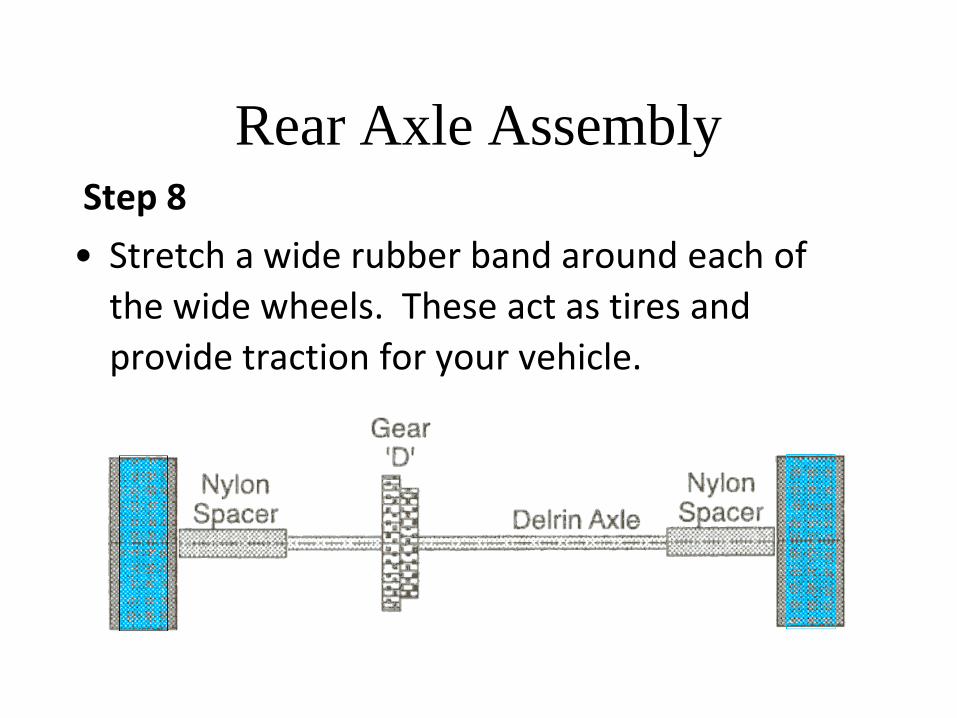
Step 8
• Stretch a wide rubber band around each of
the wide wheels. These act as tires and
provide traction for your vehicle.

Front Axle Assembly
Step 1
• Place one of the two thin wheels flat on the table. Insert one end of the remaining Delrin axle into the wheel until the end of the axle is flush with the opposite side of the wheel.
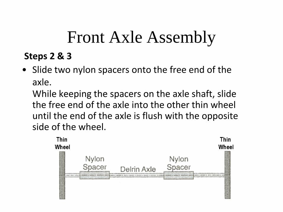
Front Axle Assembly
Steps 2 & 3
• Slide two nylon spacers onto the free end of the axle. While keeping the spacers on the axle shaft, slide the free end of the axle into the other thin wheel until the end of the axle is flush with the opposite side of the wheel.

Attaching Axle Assemblies to
Chassis Step 1
• Position the notched chassis on the table so that the notched end of the balsa is hanging over the table edge, and Lines B and C are shown.
Line C Line B
Attaching Axle Assemblies to
Chassis Step 2
Lin
e
C
Lin
e B
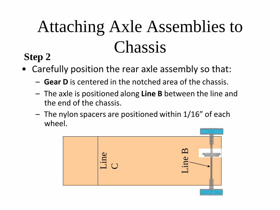
• Carefully position the rear axle assembly so that: – Gear D is centered in the notched area of the chassis.
– The axle is positioned along Line B between the line and the end of the chassis.
– The nylon spacers are positioned within 1/16” of each wheel.
Lin
e
C
Lin
e B
Attaching Axle Assemblies to Chassis
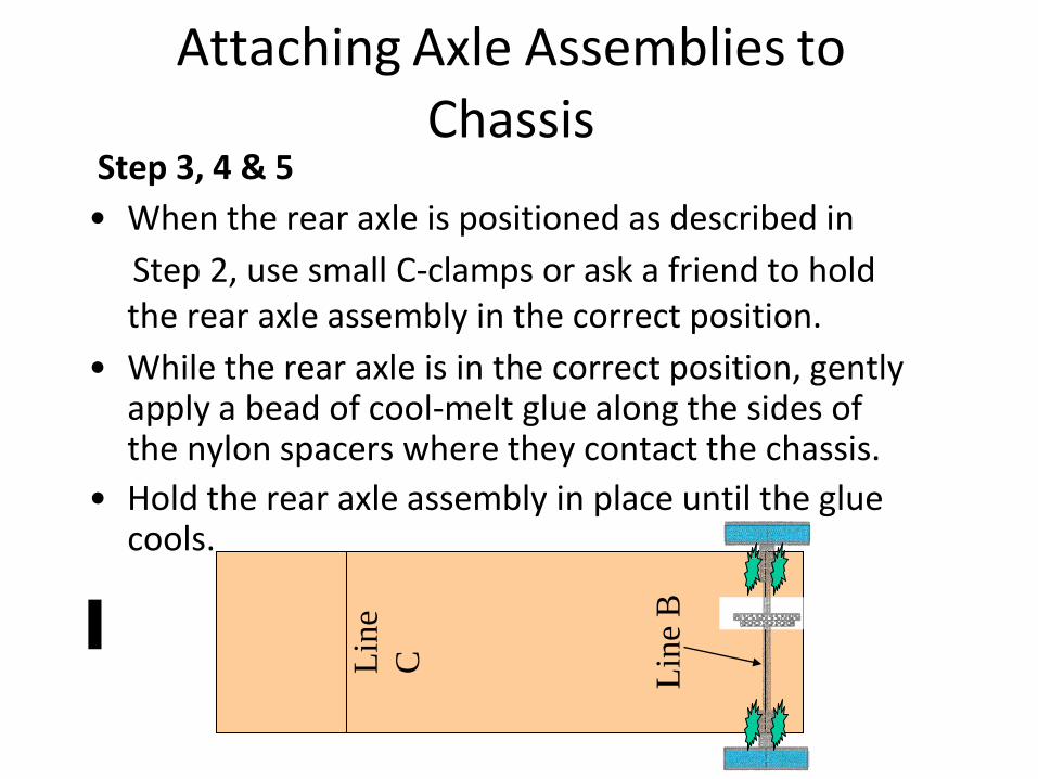
Step 3, 4 & 5
• When the rear axle is positioned as described in
Step 2, use small C-clamps or ask a friend to hold the rear axle assembly in the correct position.
• While the rear axle is in the correct position, gently apply a bead of cool-melt glue along the sides of the nylon spacers where they contact the chassis.
• Hold the rear axle assembly in place until the glue cools.
Attaching Axle Assemblies to
Chassis
Lin
e
C
Lin
e B
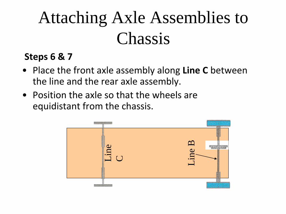
Steps 6 & 7
• Place the front axle assembly along Line C between the line and the rear axle assembly.
• Position the axle so that the wheels are equidistant from the chassis.
Attaching Axle Assemblies to
Chassis
Lin
e
C
Lin
e B
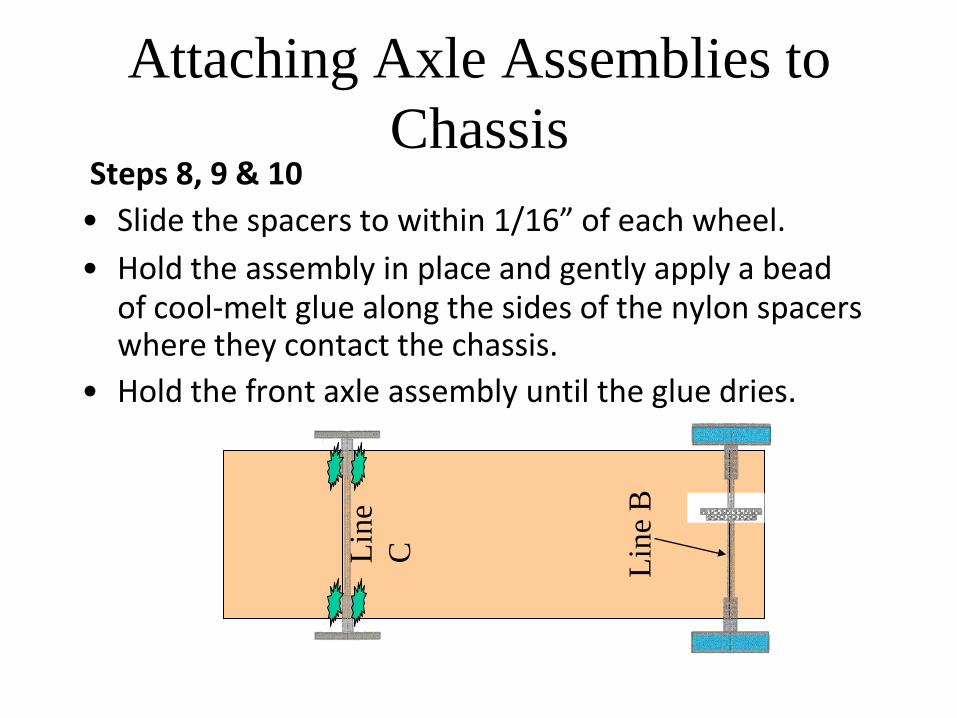
Steps 8, 9 & 10
• Slide the spacers to within 1/16” of each wheel.
• Hold the assembly in place and gently apply a bead of cool-melt glue along the sides of the nylon spacers where they contact the chassis.
• Hold the front axle assembly until the glue dries.
Attaching Motor Assembly to
Chassis
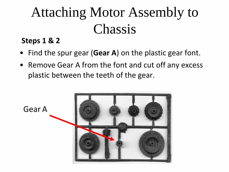
Steps 1 & 2
• Find the spur gear (Gear A) on the plastic gear font.
• Remove Gear A from the font and cut off any excess plastic between the teeth of the gear.
Gear A
Attaching Motor Assembly to
Chassis
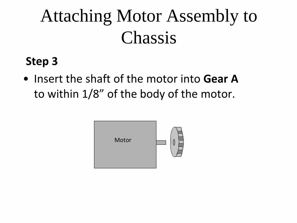
Step 3
• Insert the shaft of the motor into Gear A to within 1/8” of the body of the motor.
Motor
Attaching Motor Assembly to
Chassis
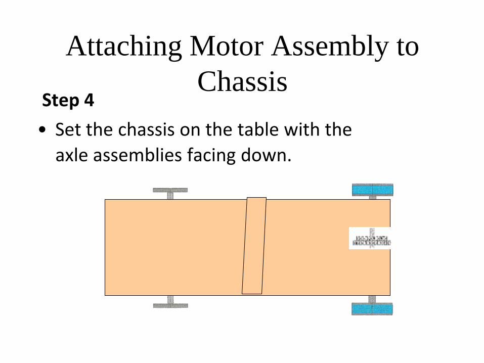
Step 4
• Set the chassis on the table with the
axle assemblies facing down.
Attaching Motor Assembly to
Chassis
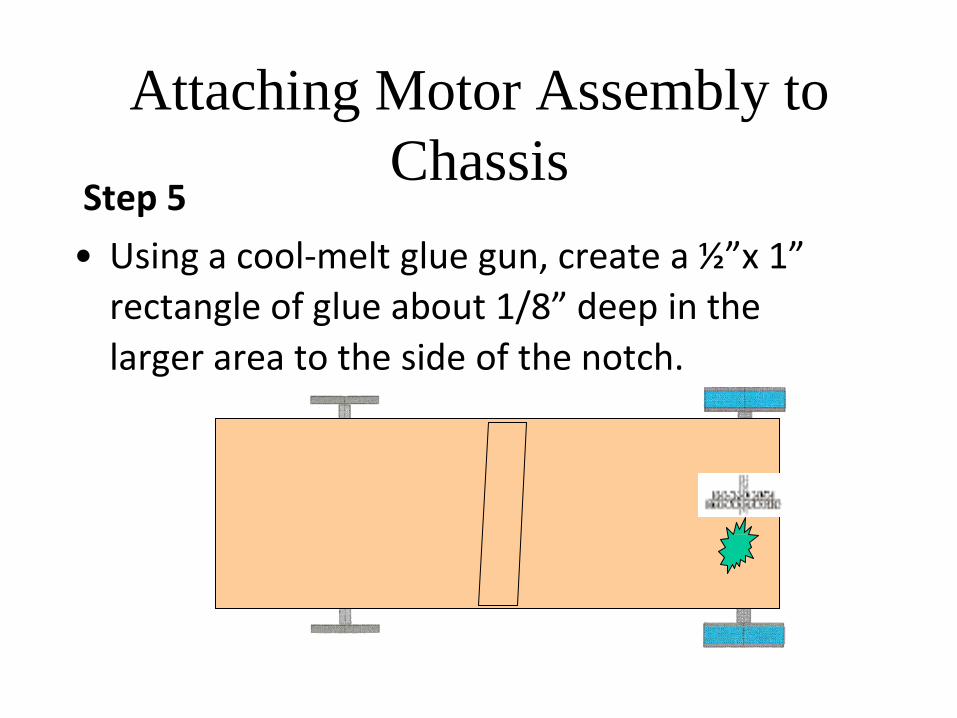
Step 5
• Using a cool-melt glue gun, create a ½”x 1”
rectangle of glue about 1/8” deep in the
larger area to the side of the notch.
Attaching Motor Assembly to
Chassis
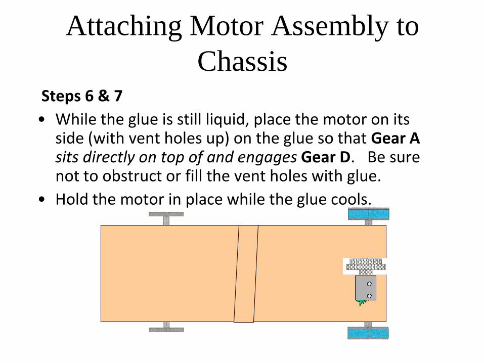
Steps 6 & 7
• While the glue is still liquid, place the motor on its side (with vent holes up) on the glue so that Gear A sits directly on top of and engages Gear D. Be sure not to obstruct or fill the vent holes with glue.
• Hold the motor in place while the glue cools.
Attaching Motor Assembly to
Chassis
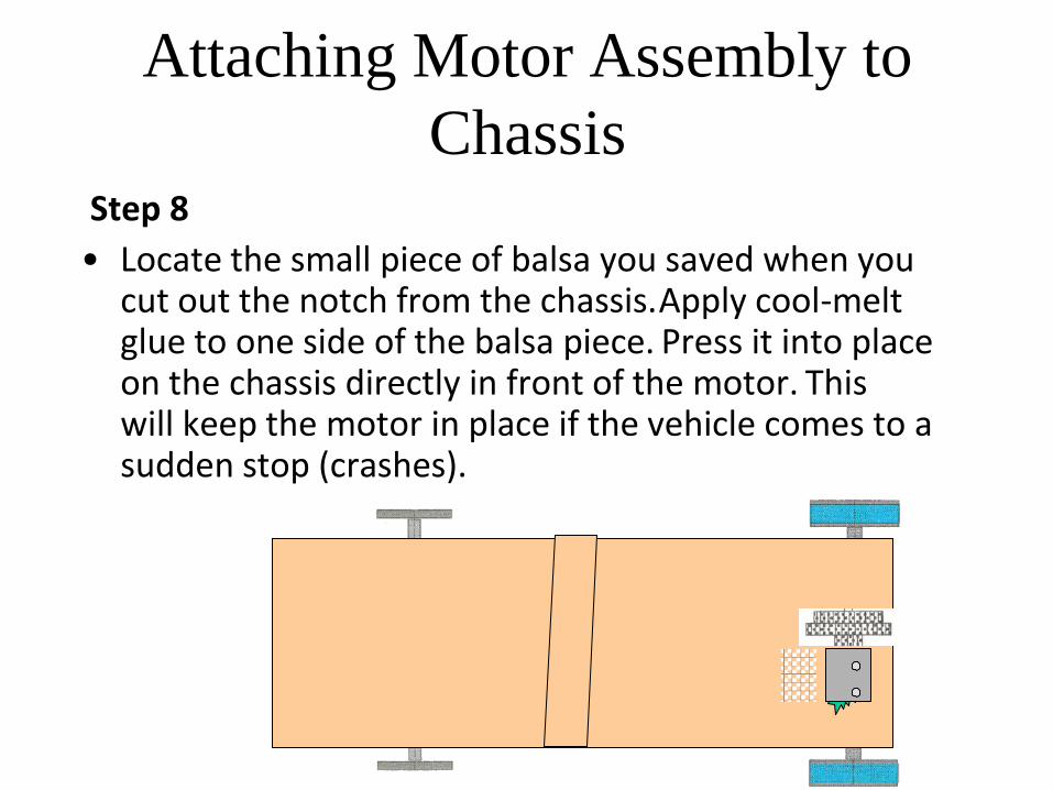
Step 8
• Locate the small piece of balsa you saved when you cut out the notch from the chassis. Apply cool-melt glue to one side of the balsa piece. Press it into place on the chassis directly in front of the motor. This will keep the motor in place if the vehicle comes to a sudden stop (crashes).
Attaching Motor Assembly to
Chassis Step 9
• If the motor dislodges, use the tip of the glue gun to soften the glue on the chassis where the motor was. Add a small amount of glue and reattach the motor as you did before.
Solar Panel Assembly
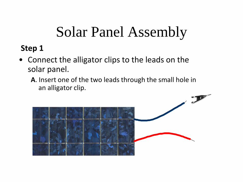
Step 1
• Connect the alligator clips to the leads on the solar panel.
A. Insert one of the two leads through the small hole in an alligator clip.
Solar Panel Assembly
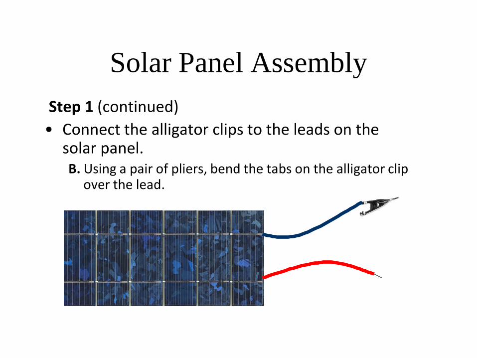
Step 1 (continued)
• Connect the alligator clips to the leads on the solar panel.
B. Using a pair of pliers, bend the tabs on the alligator clip over the lead.
Solar Panel Assembly
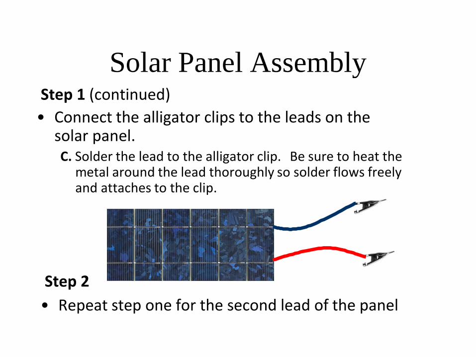
Step 1 (continued)
• Connect the alligator clips to the leads on the solar panel.
C. Solder the lead to the alligator clip. Be sure to heat the metal around the lead thoroughly so solder flows freely and attaches to the clip.
Step 2
• Repeat step one for the second lead of the panel
Final Assembly
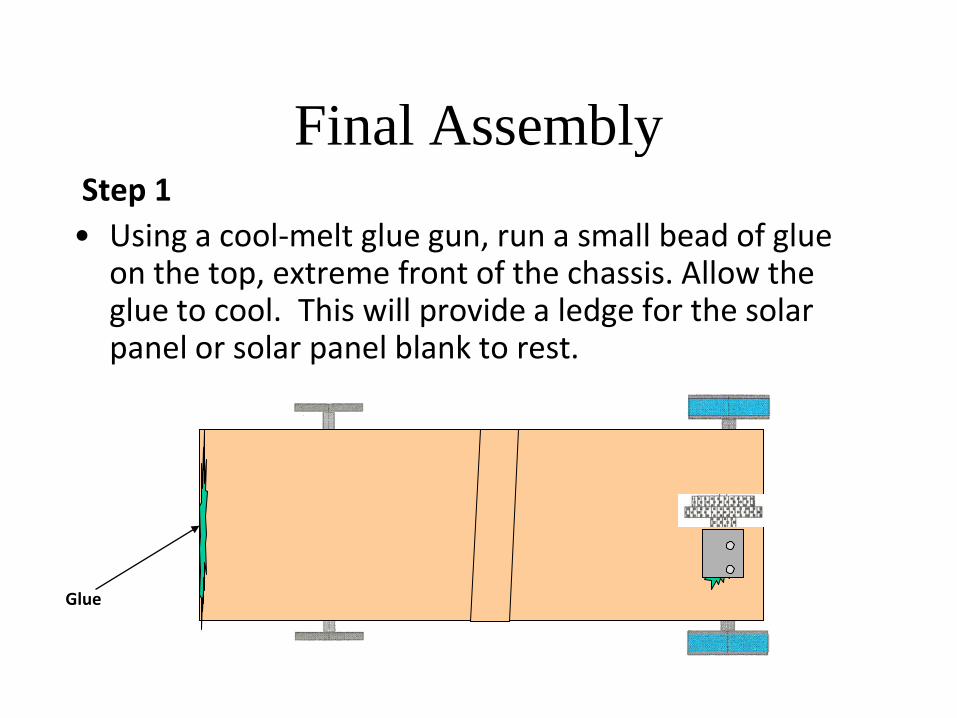
Step 1
• Using a cool-melt glue gun, run a small bead of glue on the top, extreme front of the chassis. Allow the glue to cool. This will provide a ledge for the solar panel or solar panel blank to rest.
Glue
Final Assembly
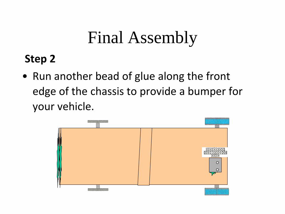
Step 2
• Run another bead of glue along the front
edge of the chassis to provide a bumper for
your vehicle.
Final Assembly
Step 3
• Position the solar panel blank on the chassis so that it rests at the front of the vehicle and on the panel support member. The blank is used to show the position and effect of the solar panel on the vehicle while you test your vehicle with the battery pack. When you are ready to test or race, use the solar panel your teacher provides and replace the blank with the solar panel.
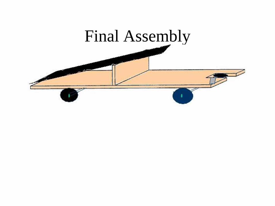
Final Assembly
Final Assembly
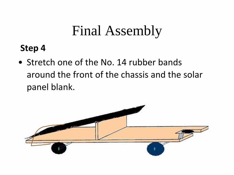
Step 4
• Stretch one of the No. 14 rubber bands
around the front of the chassis and the solar
panel blank.
Final Assembly
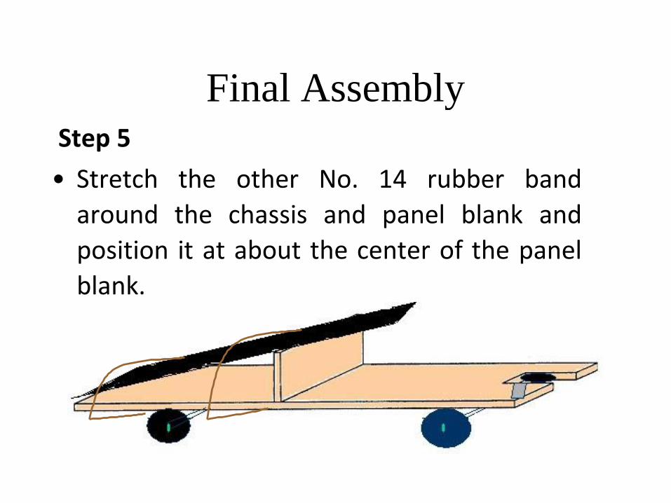
Step 5
• Stretch the other No. 14 rubber band
around the chassis and panel blank and
position it at about the center of the panel
blank.
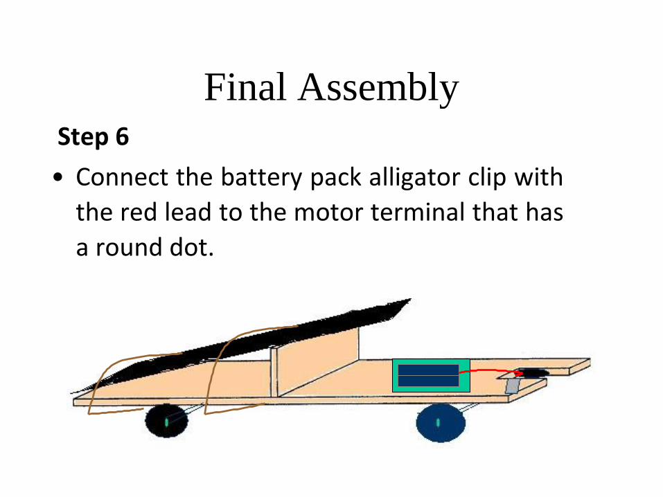
Final Assembly
Step 6
• Connect the battery pack alligator clip with
the red lead to the motor terminal that has
a round dot.
Final Assembly
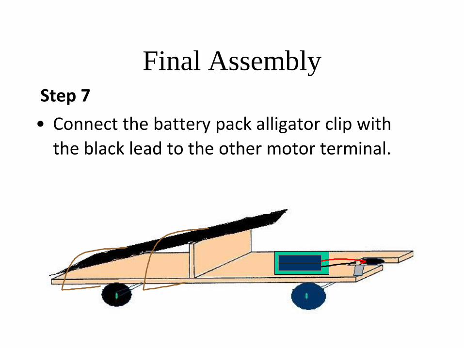
Step 7
• Connect the battery pack alligator clip with
the black lead to the other motor terminal.
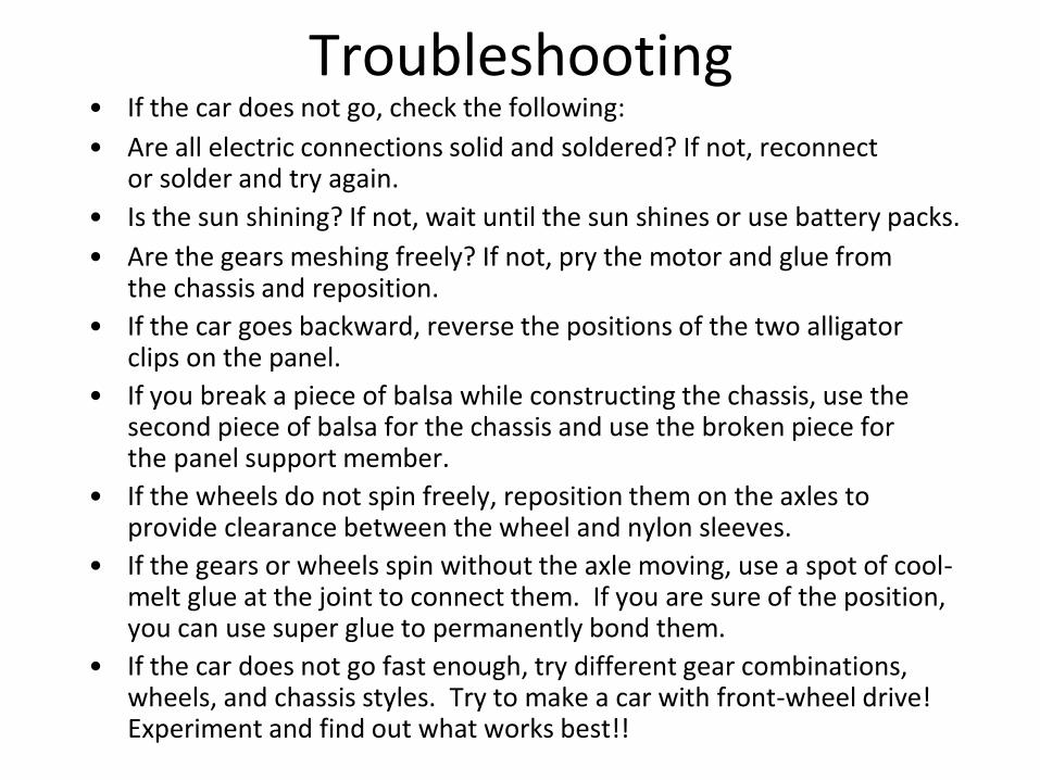
Troubleshooting • If the car does not go, check the following:
• Are all electric connections solid and soldered? If not, reconnect or solder and try again.
• Is the sun shining? If not, wait until the sun shines or use battery packs.
• Are the gears meshing freely? If not, pry the motor and glue from the chassis and reposition.
• If the car goes backward, reverse the positions of the two alligator clips on the panel.
• If you break a piece of balsa while constructing the chassis, use the second piece of balsa for the chassis and use the broken piece for the panel support member.
• If the wheels do not spin freely, reposition them on the axles to provide clearance between the wheel and nylon sleeves.
• If the gears or wheels spin without the axle moving, use a spot of cool- melt glue at the joint to connect them. If you are sure of the position, you can use super glue to permanently bond them.
• If the car does not go fast enough, try different gear combinations, wheels, and chassis styles. Try to make a car with front-wheel drive! Experiment and find out what works best!!
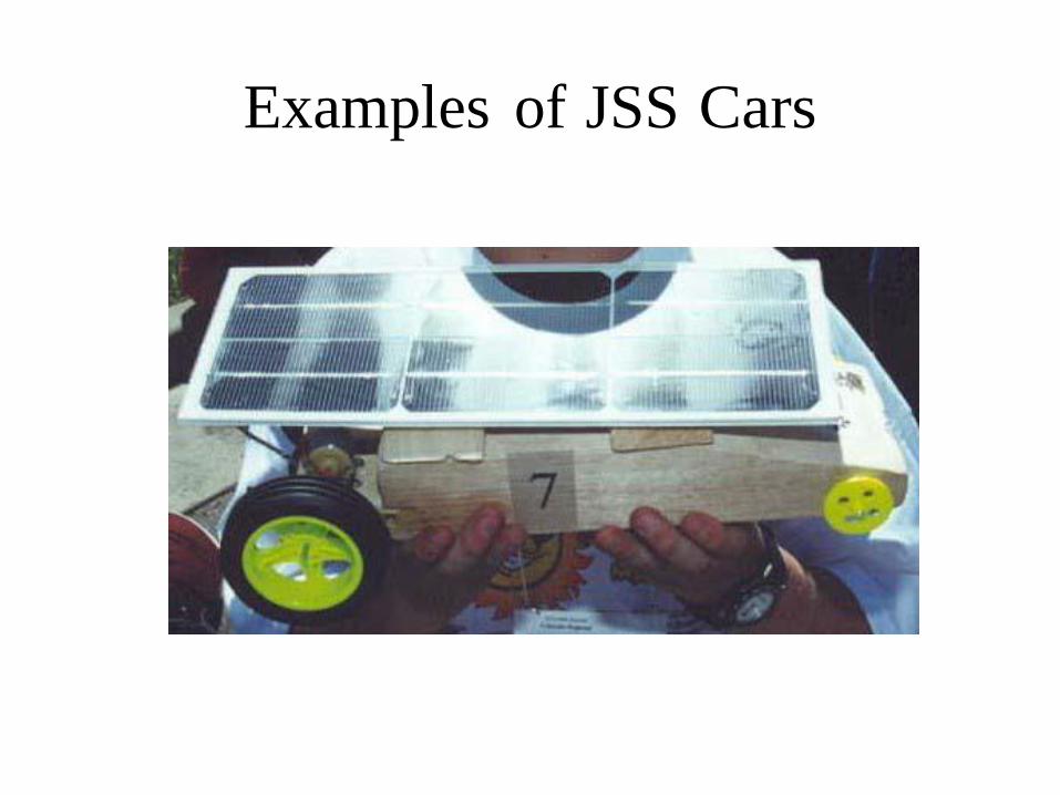
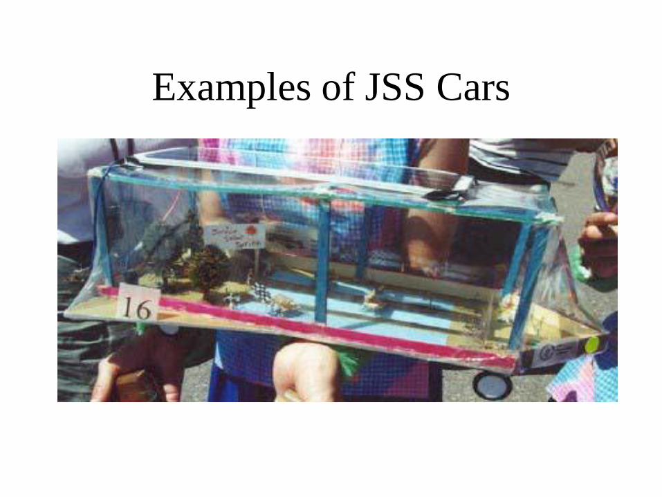
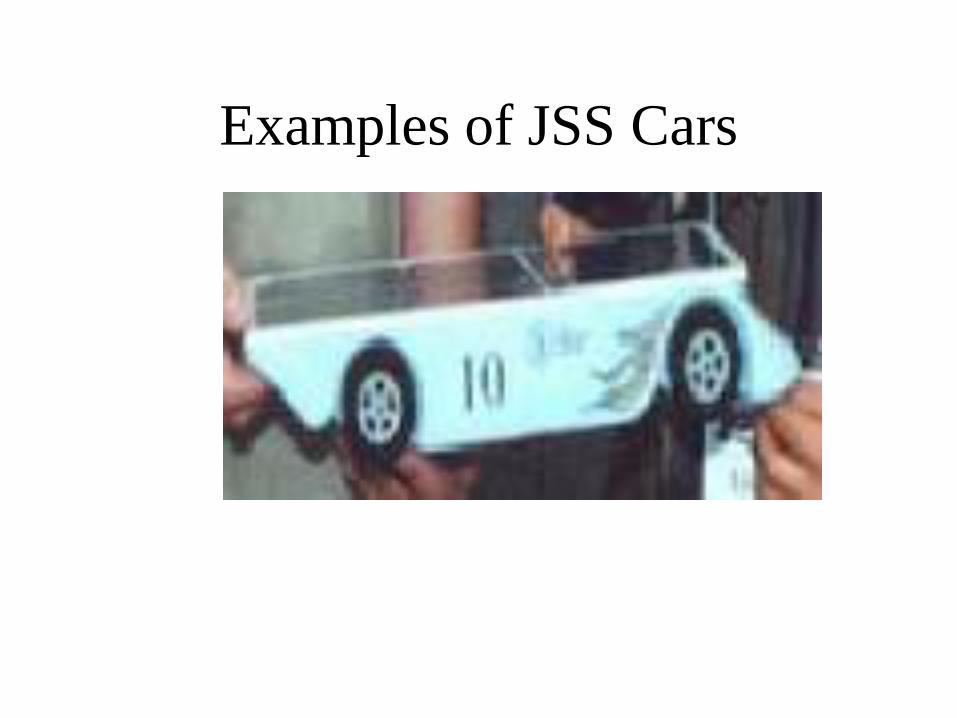
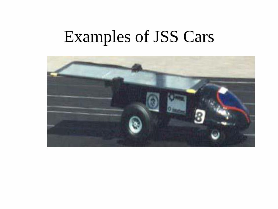
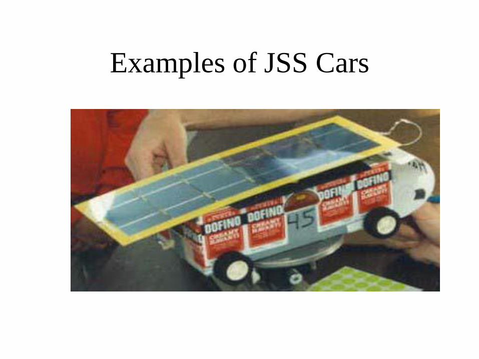
Examples of JSS Cars
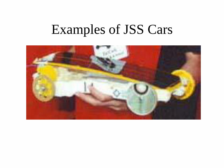
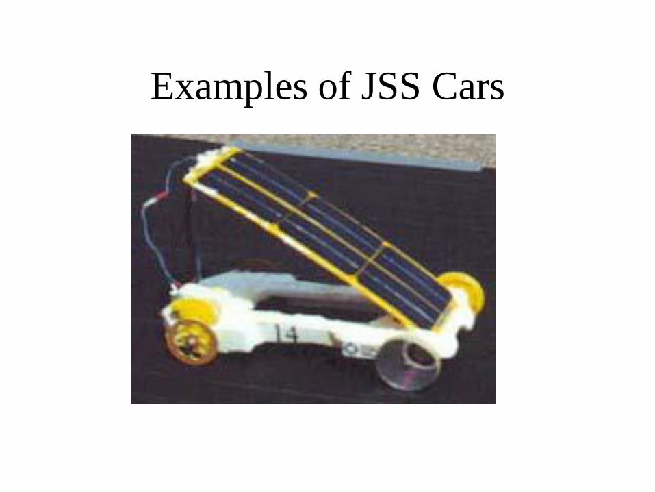
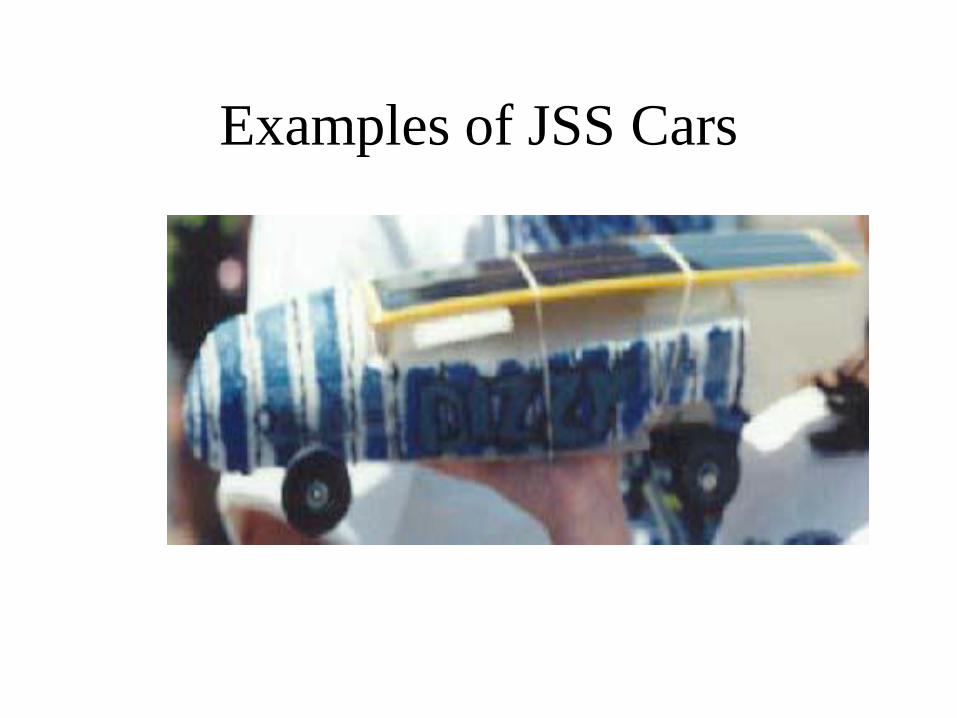
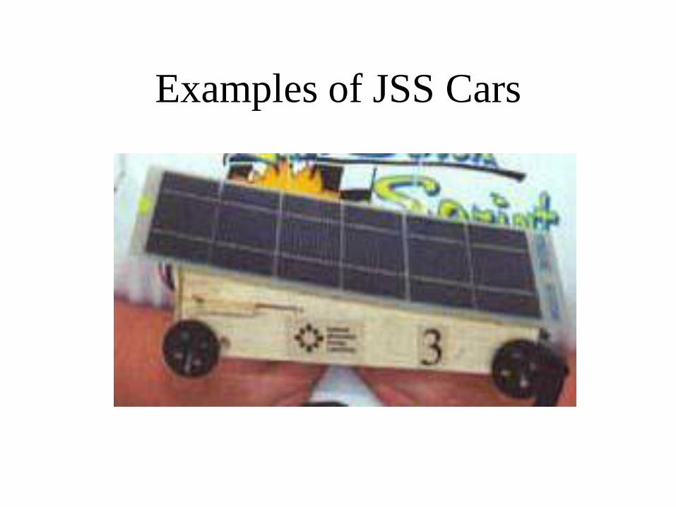
Examples of JSS Cars
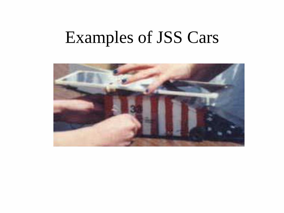
Examples of JSS Cars
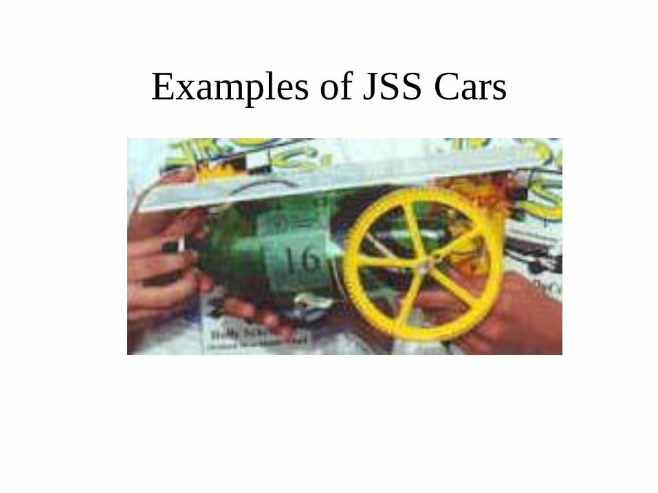
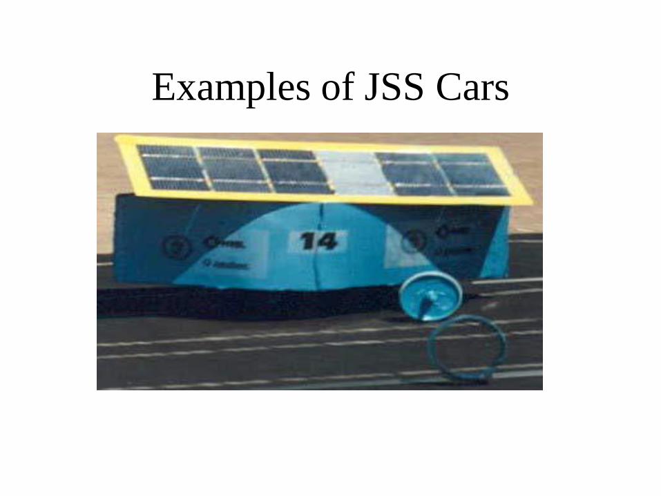
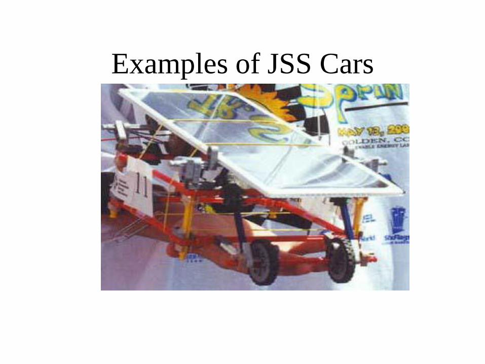
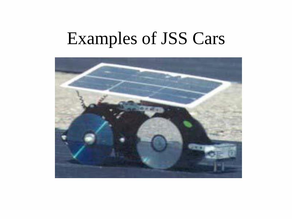
Examples of JSS Cars
Examples of JSS Cars
Examples of JSS Cars
Examples of JSS Cars
Examples of JSS Cars
Examples of JSS Cars
Examples of JSS Cars
Examples of JSS Cars
Examples of JSS Cars
Examples of JSS Cars
Examples of JSS Cars
Examples of JSS Cars
Examples of JSS Cars
Examples of JSS Cars
Examples of JSS Cars