Embed Size (px)
Citation preview

Buckling of Ship Structures

Mohamed Shama
Buckling of Ship Structures
ABC

AuthorMohamed ShamaFaculty of EngineeringNaval Architecture & Marine EngineeringAlexandria UniversityAlexandriaEgypt
ISBN 978-3-642-17960-0 e-ISBN 978-3-642-17961-7DOI 10.1007/978-3-642-17961-7Springer Heidelberg New York Dordrecht London
Library of Congress Control Number: 2012932486
c© Springer-Verlag Berlin Heidelberg 2013This work is subject to copyright. All rights are reserved by the Publisher, whether the whole or part ofthe material is concerned, specifically the rights of translation, reprinting, reuse of illustrations, recitation,broadcasting, reproduction on microfilms or in any other physical way, and transmission or informationstorage and retrieval, electronic adaptation, computer software, or by similar or dissimilar methodologynow known or hereafter developed. Exempted from this legal reservation are brief excerpts in connectionwith reviews or scholarly analysis or material supplied specifically for the purpose of being enteredand executed on a computer system, for exclusive use by the purchaser of the work. Duplication ofthis publication or parts thereof is permitted only under the provisions of the Copyright Law of thePublisher’s location, in its current version, and permission for use must always be obtained from Springer.Permissions for use may be obtained through RightsLink at the Copyright Clearance Center. Violationsare liable to prosecution under the respective Copyright Law.The use of general descriptive names, registered names, trademarks, service marks, etc. in this publicationdoes not imply, even in the absence of a specific statement, that such names are exempt from the relevantprotective laws and regulations and therefore free for general use.While the advice and information in this book are believed to be true and accurate at the date of pub-lication, neither the authors nor the editors nor the publisher can accept any legal responsibility for anyerrors or omissions that may be made. The publisher makes no warranty, express or implied, with respectto the material contained herein.
Cover design: WMX, Heidelberg
Printed on acid-free paper
Springer is part of Springer Science+Business Media (www.springer.com)
To my wife
For her love, patience, encouragement and support
To my late parents
For their continuous care and encouragement
To my students
Whose enthusiasm and hard work have encouraged me to prepare the course material of this book
Mohamed Shama
Preface
Strength members of ship hull girder are subjected to several types of static and dynamic stresses. The main stress components are the primary, secondary and tertiary stresses. Bottom plating of ship structure are subjected to additional local bending stresses induced by the external water pressure. This complex system of stresses when compounded over the thickness or cross section of a strength member could produce unacceptable high values of equivalent stresses. Because of the hostile and corrosive environment of ship operation, the strength of ship hull girder and its structural members deteriorate with time coupled with the possibility of occurrence of overloading, these strength members may fail to perform satisfactorily. Buckling of ship strength members represent one of the main modes of ship structure failure.
Because the use of the finite element method is more costly and time consuming, the introduction of simplified methods to improve design of ship strength members is always welcome. In order to achieve this goal, a comprehensive analysis is given for the determination of the compound stresses induced by the various types of loadings imposed on the different strength members of ship structure. The compounding of stresses takes account of the primary, secondary and tertiary stresses. The compounding of stresses of bottom plating takes account of the local stresses induced by the local loading of the external water pressure. The compounding of stresses is carried out at the locations expected to reveal the highest values of compound stresses. Because of the inevitable presence of geometric imperfections in ship strength members due to fabrication processes, the actual buckling strength of these members may not attain their design values.
The assessment of buckling of web plates and face plates of deck and bottom girders is presented. The assessment of buckling of side shell plating for the various induced in-plane loading conditions is presented. Assessment of buckling strength of plating for different end support conditions and for a variety of loading patterns is given. The prime aim of the book is to cover an area of ship structure analysis and design that has not been exhaustively covered by most published text books on the strength of ship structures. The book presents a practical approach for the analysis and assessment of ship strength members with particular emphasis on the buckling strength of ship structural members. The book, therefore, contains the main equations required to determine the critical buckling stress for both ship plating and the primary and secondary stiffening members. The critical buckling stress is given for ship plating having the most common boundary conditions
VIII Preface
encountered in ship structures and subjected to the compound in-plane stresses. The methods commonly used to control buckling failure are introduced.
The book should bridge the gap existing in most books covering the subject of buckling of ship structures by putting the emphasis on the practical methods required to ensure safety against buckling of ship strength members. The book should be very useful to ship designers, shipyard engineers, naval architects, international classification societies and also to students studying naval architecture, marine engineering and offshore structures. The book is enhanced with a set of some solved and unsolved problems.

Outline of the Book
The book is composed of 14 Chapters. The first 13 Chapters are divided into Three Parts. The last Chapter presents a set of problems on the subject material given in the book.
Part I
Part I is Composed of Four chapters
Chapter 1 presents the basic configurations and structural features of some ship types. The main design features of single and double side bulk carriers are presented. The main types and categories of bulk carriers are classified. The structural components of single and double skin bulk carriers as well as the construction of double bottom are specified. The commonly used abbreviations to describe the different types and sizes of bulk carriers are enumerated. The main types and structural characteristics of general cargo and container ships are highlighted. The basic arrangements and design features of Ro-Ro ships are described. The structural systems and design features of single and double hull tankers are clarified. The advantages and drawbacks of the double-hull design are clarified.
Chapter 2 presents the main configurations and characteristics of ship structural assemblies. Transversely and longitudinally stiffened bottom, deck and side shell structure assemblies are considered. The main structural features of transverse bulkheads are described. A brief description of the scantlings of ship strength members is introduced. The basic role of classification societies is clarified. Some ship structural connections and details such as frame brackets, beam and tripping brackets, etc. are illustrated.
Chapter 3 presents the main configurations and geometrical properties of ship structure members. The structural features of ship stiffened panels and frameworks are clarified. Standard and fabricated sections commonly used as stiffening members in ship construction are addressed. The geometrical properties of the various stiffening members with attached plating are presented. The effect of variation of thickness of attached plating on the magnitude of section modulus and second moment of area is quantified. Geometrical and flexural properties of curved plates are given. Equivalent rolled and fabricated sections of commonly used sections of ship strength members are explained. Rational shapes of cross-sections
X Outline of the Book
of beams and columns are given. Procedures for the design of fabricated T and I-sections are presented.
Chapter 4 introduces the application of the simple beam theory to ship structural members. The limitations of application of the simple beam theory to thin-walled asymmetrical sections are highlighted. A full explanation of the idealization of beam elements is illustrated. The effective breadth concept is explained for uniform and curved structural members. The concept of modeling ship structure assemblies by beam elements is introduced. Several examples of 2D and 3D modeling of deck, bottom and side structures using beam and plate elements are illustrated. The various types of boundary end conditions commonly used in ship structure analysis are given. The concept of span points and effective span of a beam are clarified. A method is given to determine the optimum span length of a beam and the size of the attached brackets. The influence of the type of end support on the magnitude and distribution of the bending moment are presented. Bending stresses in beams constructed with high tensile steel is clarified. Flexural stresses in fabricated symmetrical and asymmetrical sections are presented. The importance of calculating the equivalent stress is highlighted. A simple procedure for calculating flexural warping stresses is given. The main parameters affecting the magnitude and distribution of flexural warping stresses for asymmetrical sections are explained. The basic concept of effective breadth of uniform symmetrical and asymmetrical face plates is introduced.
Part II
Part II is Composed of Five Chapters
Chapter 5 presents the main components of hull girder bending moments, shear forces and torsion moments. Design values given by Classification societies for still water and wave induced vertical, horizontal and torsional moments are given. An approximate estimate of the maximum value of the wave induced bending moment is given. The distribution of the largest expected vertical wave-induced shearing force is presented. A method is given to determine an approximate value of the maximum vertical shear force. Hull girder dynamic shear force and bending moment components are clarified. The dynamic loading due to shipping green seasis described. The phenomenon of springing resulting from the hydrodynamic loadings induced by the periodic loads generated by the wave actions is explained. The terms "slamming" and "pounding" describing forward bottom impact are explained. The effect of ship hull girder longitudinal vertical deflection on the distribution of shear force and bending moment along ship length is studied. The short and long term predictions of hull girder loadings is given together with an approach to predict their extreme values.
Chapter 6 presents the methods commonly used for the calculation of the primary stresses induced by the vertical and horizontal hull girder bending moments. The strength members of ship hull girder sustaining the primary hull girder stresses are specified. The common procedures used for the calculation of ship section geometrical and flexural properties are given. The method of

Outline of the Book XI
calculating hull girder bending stresses when the ship is in the inclined condition is presented.
Chapter 7 gives a full analysis of the secondary loadings and stresses induced in ship structural assemblies of cargo ships and conventional oil tankers. Strength members sustaining secondary loadings and stresses of transversely and longitudinally stiffened bottom and deck ship structure assemblies are specified. The secondary stresses induced by the bending of double and single bottom structures are presented for hogging and sagging conditions. The loadings and stresses induced in deck and bottom girders, longitudinals and plating are highlighted. Secondary loadings and stresses induced in tank top longitudinals and plating are given. Secondary loading and stresses in bottom structure assemblies of oil tankers are identified.
Chapter 8 gives a comprehensive analysis of the tertiary loadings and stresses induced in the various strength members of longitudinally and transversely stiffened ship structure. The tertiary strength members of longitudinally and transversely stiffened deck and bottom structures are specified. The tertiary loadings and stresses induced in deck, bottom and tank top longitudinals and plating are presented. The local loadings and stresses induced in transversely and longitudinally stiffened bottom plating is explained. A method is given to determine the minimum required thickness of bottom plating of ship structure.
Chapter 9 gives a full analysis of the compounding of stresses induced in the various ship strength members of transversely and longitudinally stiffened double bottom and deck structures.The compounding of stresses is carried out for the main strength members of a ship which includes girders, longitudinals and plating. The compounding of stresses induced in any strength member takes account of the primary, secondary and tertiary stresses. The primary stresses included in the compounding process are calculated when the ship is in sagging condition when compounding is carried out for deck strength members and for the strength members of the bottom structure when the ship is in hogging condition. The compounding of stresses in tank top longitudinals and plating are also considered. The compounding of stresses of bottom plating takes account of the local stresses induced by the local loading of water pressure. The locations of compounding of stresses expected to reveal the highest values of stresses are identified.
Part III
Part III is Composed of Four Chapters
Chapter 10 presents the stability phenomenon of ship structure. The basic equations of buckling of columns and beam columns are given. The most common classes of perturbations experienced by beam columns are identified. The physical problem of stability is explained and is defined by its state of equilibrium. The concept of critical force and critical stress are explained. The effect of eccentric loading on the critical buckling critical stress is given. The load-deflection relationship of beam columns is introduced. The behavior of beam columns under various loading conditions and different types of end supports are investigated.
XII Outline of the Book
Chapter 11 presents comprehensive analysis of buckling of stiffened panels. Global and local buckling modes of deformation of stiffened panels are given. The commonly used idealizations of boundary support conditions of ship plating are clarified. The general equations for plate buckling under single and combined loading patterns are considered. The basic and Interaction equations of buckling of plating subjected to a variety of combined system of loadings are given. The concept of effective width of plating is clarified. The non-uniform in-plane compressive loadings are idealized by the combined loadings of uniform compression and pure bending. The various boundary conditions commonly assumed for girders and plating is given. The general modes of buckling of face plates and web plates of girders are illustrated. Post–buckling strength of plating is introduced. Ultimate stress of simply supported plate panels is given.
Chapter 12 presents simplified procedures for the assessment of buckling of ship strength members. The main strength members of longitudinally and transversely stiffened bottom and deck structures sustaining compressive forces are identified. The compressive loadings are the compound in-plane stresses induced by the hull girder, secondary, and tertiary stresses. The assessment of buckling of web plates and face plates of deck and bottom girders is presented. Assessment of buckling strength of plating for different end support conditions and for a variety of loading patterns is given. The assessment of buckling strength of strength members of bottom structure is carried out when the ship is in hogging condition and for strength members of deck structure when the ship is in sagging condition. For both cases, the compounding of stresses is carried out when the secondary and tertiary loadings are inducing compressive stresses. The assessment of buckling of side shell plating for various induced in-plane loading conditions is presented. The importance of ensuring that ship strength members sustaining compressive forces have adequate buckling strength against buckling failure is stressed.
Chapter 13 gives a detailed analysis of the various measures commonly used to control buckling of ship structural members. Reliability basis of ship structural safety is introduced. The role of Classification societies in controlling failure of ship structural members is explained. The deleterious effects of deterioration of strength of ship structural members with time are highlighted. The effect of corrosion of ship strength members on the flexural rigidity and buckling strength are described. Linear and exponential equations are used for modeling the variation of the rate of corrosion with time. Improved designs to control buckling failure of ship structural details and connections are presented. Commonly used owners approach for improving ship safety is given. The most common design and construction measures adopted to control welding distortions are specified. Measures to control fabrication deformations and warping of steel sections are clarified. The importance of improving control on tolerances of ship structure members and quality of ship fabrication processes is stressed.
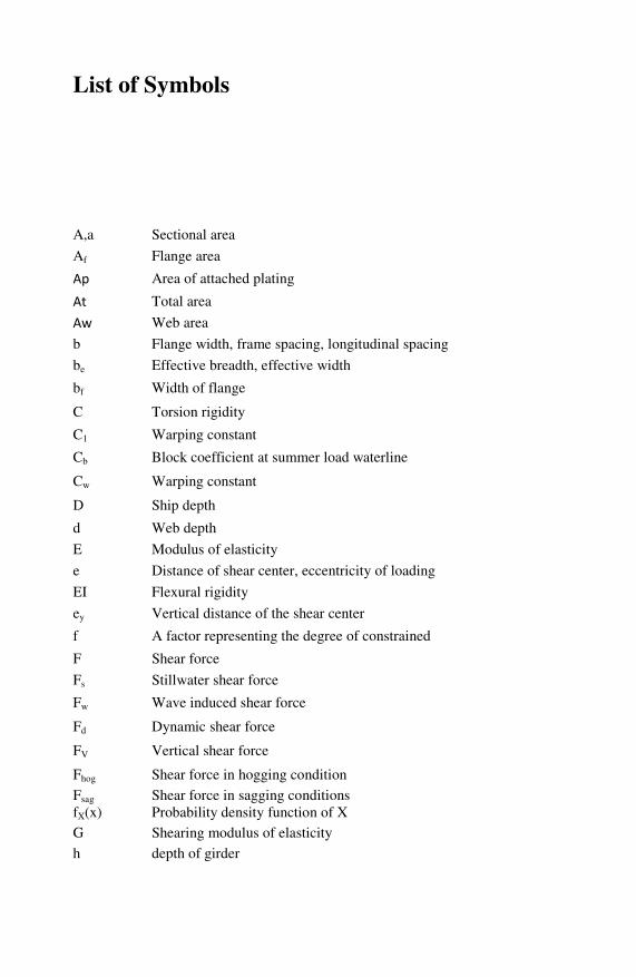
List of Symbols
A,a Sectional area
Af Flange area
Ap Area of attached plating
At Total area
Aw Web area
b Flange width, frame spacing, longitudinal spacing
be Effective breadth, effective width
bf Width of flange
C Torsion rigidity
C1 Warping constant
Cb Block coefficient at summer load waterline
Cw Warping constant
D Ship depth
d Web depth
E Modulus of elasticity
e Distance of shear center, eccentricity of loading
EI Flexural rigidity
ey Vertical distance of the shear center
f A factor representing the degree of constrained
F Shear force
Fs Stillwater shear force
Fw Wave induced shear force
Fd Dynamic shear force
FV Vertical shear force
Fhog Shear force in hogging condition
Fsag Shear force in sagging conditions fX(x) Probability density function of X G Shearing modulus of elasticity
h depth of girder
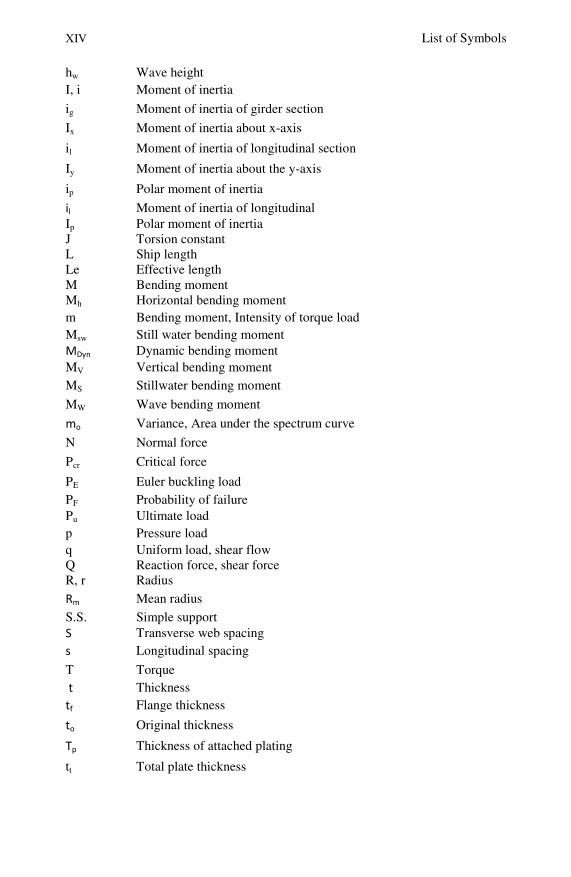
XIV List of Symbols
hw Wave height I, i Moment of inertia
ig Moment of inertia of girder section
Ix Moment of inertia about x-axis
il Moment of inertia of longitudinal section
Iy Moment of inertia about the y-axis
ip Polar moment of inertia
il Moment of inertia of longitudinal Ip Polar moment of inertia J Torsion constant L Ship length Le Effective length M Bending moment Mh Horizontal bending moment m Bending moment, Intensity of torque load Msw Still water bending moment MDyn Dynamic bending moment MV Vertical bending moment MS Stillwater bending moment
MW Wave bending moment
mo Variance, Area under the spectrum curve
N Normal force
Pcr Critical force
PE Euler buckling load PF Probability of failure Pu Ultimate load p Pressure load q Uniform load, shear flow Q Reaction force, shear force R, r Radius
Rm Mean radius
S.S. Simple support S Transverse web spacing s Longitudinal spacing
T Torque t Thickness tf Flange thickness
to Original thickness
Tp Thickness of attached plating
tt Total plate thickness
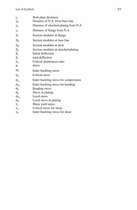
List of Symbols XV
tw Web plate thickness yD Distance of N.A. from base line yp Distance of attached plating from N.A
yf Distance of flange from N.A.
Zf Section modulus at flange
ZB Section modulus at base line
ZD Section modulus at deck Zp Section modulus at attached plating δo Initial deflection δt total deflection λcr Critical slenderness ratio σ stress
σE Euler buckling stress
σcr Critical stress
σec Euler buckling stress for compression
σeb Euler buckling stress for bending σb Bending stress σp Stress in plating σloc Local stress σpl Local stress in plating τy Shear yield stress τcr Critical stress for shear τes Euler buckling stress for shear
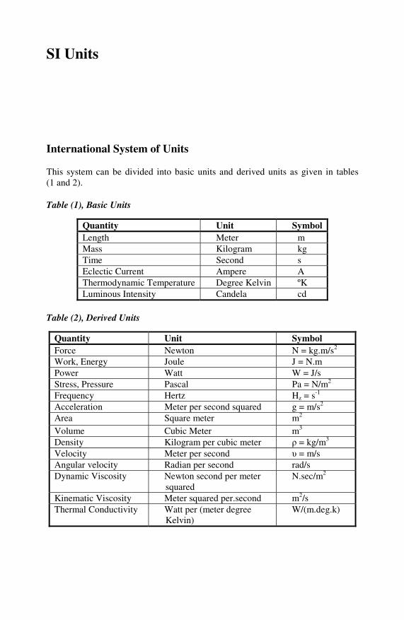
SI Units
International System of Units
This system can be divided into basic units and derived units as given in tables (1 and 2).
Table (1), Basic Units
Quantity Unit Symbol Length Meter m Mass Kilogram kg Time Second s Eclectic Current Ampere A Thermodynamic Temperature Degree Kelvin ºK Luminous Intensity Candela cd
Table (2), Derived Units
Quantity Unit Symbol Force Newton N = kg.m/s2 Work, Energy Joule J = N.m Power Watt W = J/s Stress, Pressure Pascal Pa = N/m2 Frequency Hertz Hz = s-1 Acceleration Meter per second squared g = m/s2 Area Square meter m2 Volume Cubic Meter m3
Density Kilogram per cubic meter ρ = kg/m3 Velocity Meter per second υ = m/s Angular velocity Radian per second rad/s Dynamic Viscosity Newton second per meter
squared N.sec/m2
Kinematic Viscosity Meter squared per.second m2/s Thermal Conductivity Watt per (meter degree
Kelvin) W/(m.deg.k)
XVIII SI Units
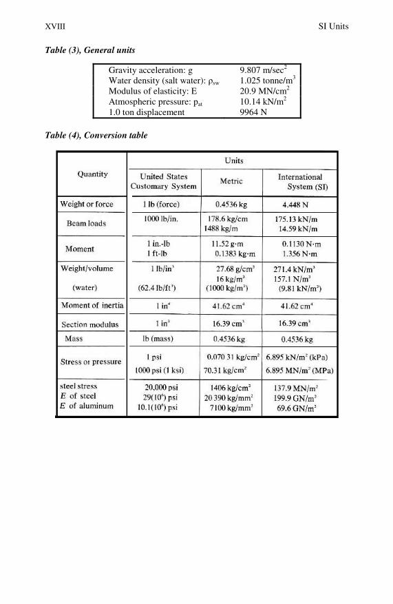
Table (3), General units
Gravity acceleration: g 9.807 m/sec2 Water density (salt water): ρsw 1.025 tonne/m3
Modulus of elasticity: E 20.9 MN/cm2 Atmospheric pressure: pat 10.14 kN/m2 1.0 ton displacement 9964 N
Table (4), Conversion table

Contents
Part I: Chapter 1 – Chapter 4 Chapter 1: Ship Structure Configurations and Main Characteristics............. 3 1 Introduction .................................................................................................. 3 2 Ship Types and Main Characteristics ........................................................... 3
2.1 Bulk Carriers ........................................................................................ 3 2.2 Double Sides Bulk Carriers.................................................................. 6 2.3 Bottom Structure of Bulk Carriers ....................................................... 7 2.4 Types and Categories of Bulk Carriers ................................................ 7 2.5 Main Structural Components of Single Skin Bulk Carriers ................. 8
3 General Cargo Ships ................................................................................... 10 4 Container Ships........................................................................................... 14 5 RoRo Ships ................................................................................................. 17
5.1 Ramps Types and Arrangements in Ro-Ro Ships .............................. 18 6 Tankers ....................................................................................................... 19
6.1 Single Hull Tankers (Conventional Construction) ............................. 19 6.2 Design Features of Double Hull Tankers ........................................... 21 6.3 Structural System of Double Hull Structure....................................... 22 6.4 Double Bottom and Double Side Construction of Oil Tankers .......... 23
Chapter 2: Configurations and Characteristics of Ship Structural Assemblies ........................................................................................ 25 1 Introduction ................................................................................................ 25 2 Ship Structural Assemblies......................................................................... 25 3 Bottom Structure......................................................................................... 25
3.1 Single Bottom Structure ..................................................................... 25 3.2 Double-Bottom Structure ................................................................... 26 3.3 Transversely Framed Double Bottom ................................................ 27 3.4 Longitudinally Framed Double Bottom ............................................. 28
4 Side Shell Structure .................................................................................... 29 4.1 Transversely Framed Side Shell Structure Assemblies ...................... 30 4.2 Longitudinally Framed Side Shell Structure ...................................... 31
5 Deck Structure ............................................................................................ 31 5.1 Deck Plating ....................................................................................... 32 5.2 Transversely Stiffened Deck Plating .................................................. 33 5.3 Longitudinally Stiffened Deck Structure............................................ 33
XX Contents
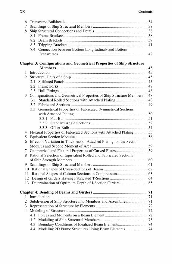
6 Transverse Bulkheads ................................................................................. 34 7 Scantlings of Ship Structural Members ...................................................... 38 8 Ship Structural Connections and Details .................................................... 38
8.1 Frame Brackets................................................................................... 38 8.2 Beam Brackets ................................................................................... 39 8.3 Tripping Brackets............................................................................... 41 8.4 Connection between Bottom Longitudinals and Bottom
Transverses ........................................................................................ 42 Chapter 3: Configurations and Geometrical Properties of Ship Structure Members .......................................................................................... 45 1 Introduction ................................................................................................ 45 2 Structural Units of a Ship ........................................................................... 45
2.1 Stiffened Panels.................................................................................. 45 2.2 Frameworks........................................................................................ 47 2.3 Hull Fittings ....................................................................................... 48
3 Configurations and Geometrical Properties of Ship Structure Members.... 48 3.1 Standard Rolled Sections with Attached Plating ............................... 48
3.2 Fabricated Sections ............................................................................ 49 3.3 Geometrical Properties of Fabricated Symmetrical Sections
with Attached Plating......................................................................... 50 3.3.1 Flat-Bar .................................................................................. 51 3.3.2 Standard Angle Sections ........................................................ 52 3.3.3 Offset Bulb ............................................................................. 54
4 Flexural Properties of Fabricated Sections with Attached Plating.............. 55 5 Equivalent Section Modulus ....................................................................... 56 6 Effect of Variation in Thickness of Attached Plating on the Section Modulus and Second Moment of Area ....................................................... 59 7 Geometrical and Flexural Properties of Curved Plates ............................... 59 8 Rational Selection of Equivalent Rolled and Fabricated Sections of Ship Strength Members .......................................................................... 60 9 Scantlings of Ship Structural Members ...................................................... 61 10 Rational Shapes of Cross-Sections of Beams ........................................... 62 11 Rational Shapes of Column Sections in Compression.............................. 63 12 Design of Girders Having Fabricated T-Sections ..................................... 64 13 Determination of Optimum Depth of I-Section Girders ........................... 65 Chapter 4: Bending of Beams and Girders ...................................................... 71 1 Introduction ................................................................................................ 71 2 Subdivision of Ship Structure into Members and Assemblies.................... 71 3 Representation of Structure by Elements.................................................... 72 4 Modeling of Structure................................................................................. 72
4.1 Forces and Moments on a Beam Element .......................................... 72 4.2 Modeling of Ship Structural Members ............................................... 73 4.3 Boundary Conditions of Idealized Beam Elements............................ 74 4.4 Modeling 2D Frame Structures Using Beam Elements...................... 74

Contents XXI
4.5 Modeling 2D Grillage Structure......................................................... 75 4.6 Modeling 2D Deck Structure ............................................................. 75 4.7 Modeling 2D Bottom Structure .......................................................... 75 4.8 Modeling 2D Side Structure............................................................... 76 4.9 Modeling 2D Transverse Bulkhead.................................................... 76 4.10 Modeling 3D Space Frame Structures Using Beam Elements ......... 77
5 Modeling by Using Plate Elements............................................................. 77 5.1 FEM Idealization Using Plate Elements............................................. 78
6 Boundary Conditions of Beams and Columns............................................ 80 7 Effective Span of a Beam ........................................................................... 80 8 Determination of the Optimum Span Length and Size of Bracket ............. 82 9 Simple Beam Theory .................................................................................. 83
9.1 Beam Loading and Response ............................................................. 83 9.2 Beam Deflections ............................................................................... 87
10 The Influence of the Type of End Support on the Magnitude and Distribution of the Bending Moment ........................................................ 89
10.1 Effect of Degree of Constraint at the End Support on the Magnitude and Distribution of the Bending Moment ..................... 90
10.2 General Case of Uniform Loading and Constrained End Supports.................................................................................. 91
11 Beam Stresses ........................................................................................... 93 11.1 Beam under Normal (Axial) Loading............................................. 93 11.2 Beams Subjected to Bending Stresses ............................................ 93
11.2.1 Bending of Symmetrical Sections ..................................... 93 11.2.2 Bending of Sections with One Axis of Symmetry............. 94
11.3 Bending of Asymmetrical Sections ................................................ 95 12 Bending Stresses in Beams Constructed with High Tensile Steel ............ 96 13 Equivalent Stress ...................................................................................... 97 14 Flexural Stresses in Fabricated Asymmetrical Sections ........................... 98
14.1 A Simple Procedure for Calculating Flexural Warping Stresses..... 99 14.2 Main Parameters Affecting the Magnitude and Distribution
of Flexural Warping Stresses ........................................................ 103 15 Effective Breadth Concept...................................................................... 105
15.1 Effective Breadth of Uniform Symmetrical Sections................... 106 15.2 Effective Flexural Properties of Sections ..................................... 107 15.3 Effective Breadth of Asymmetrical Face Plates........................... 110 15.4 Effective Breadth of Curved Face Plates...................................... 112
15.4.1 Symmetrical Face Plates.................................................. 112 15.4.2 Asymmetrical Face Plate................................................. 113
Part II: Chapter 5 – Chapter 9 Chapter 5: Hull Girder Loading ..................................................................... 117 1 Introduction .............................................................................................. 117 2 The Nature of Hull Girder Loads.............................................................. 117 3 Classification of Hull Girder Loads.......................................................... 118

XXII Contents
4 Hull Girder Longitudinal Vertical Bending Moments .............................. 118 4.1 Stillwater Shear Force and Bending Moment................................... 118 4.2 Wave-Induced Component............................................................... 120
5 Effect of Hull Girder Vertical Deflection on the Distribution of Shear Force and Bending Moment along Ship Length......................... 120
5.1 Shear Force and Bending Moment Correction due to Ship Deflection ................................................................................ 123
6 Hydrodynamic Loads................................................................................ 124 6.1 Dynamic Loadings due to Shipping Green Seas .............................. 126
7 Hull Girder Dynamic Shear Force and Bending Moment ........................ 127 8 Hull Girder Design Vertical Bending Moment......................................... 128
8.1 Standard Still Water Bending Moments........................................... 128 8.2 Vertical Wave Bending Moment...................................................... 129
8.3 An Approximate Estimate of the Maximum Value of the Wave Induced Bending Moment MW ............................................... 130 9 Horizontal Bending Moment .................................................................... 130 10 Hull Girder Shearing Forces ................................................................... 131
10.1 Total Vertical Shearing Force FV .................................................. 131 10.2 Stillwater Shear Force Component FS ........................................... 132 10.3 The Distribution of the Vertical Wave-Induced Shearing Force ... 133 10.4 Approximate Value of the Maximum Vertical Shear Force.......... 133
11 Wave Induced Torsion Loading ............................................................. 134 12 Probabilistic Prediction of Hull Girder Loading..................................... 137
12.1 Short Term Prediction of Loading................................................. 137 12.2 Long Term Predictions.................................................................. 139 12.3 Extreme Value Distributions ........................................................ 139
Chapter 6: Hull Girder Bending Stresses....................................................... 141 1 Introduction .............................................................................................. 141 2 Hull Girder Bending Stress Components.................................................. 141
2.1 Hull Girder Primary Stresses Induced by Longitudinal Vertical Bending Moments............................................................................ 142
3 Geometrical and Flexural Properties of Ship Sections ............................. 145 3.1 Flexural Properties of Longitudinally Framed Deck and
Bottom Structures ............................................................................ 147 4 Hull Girder Stresses When the Ship Is In the Inclined Condition ............ 149 5 Hull Girder Stresses due to Horizontal Bending Moment ........................ 150 6 Hull Girder Shear Stresses........................................................................ 151 Chapter 7: Secondary Loading and Stresses.................................................. 153 1 Introduction .............................................................................................. 153 2 Strength Members of Ship Bottom Assemblies Sustaining Secondary Loadings.................................................................................. 153
2.1 Secondary Loading and Stresses in Bottom Assemblies.................. 154 2.2 Secondary Loading and Stresses in Transversely Stiffened
Bottom Assemblies .......................................................................... 154

Contents XXIII
2.2.1 Secondary Loading and Stresses in Bottom Girders ............ 155 2.2.2 Secondary Stresses in Bottom Plating .................................. 156 2.2.3 Secondary Stresses in Tank Top Plating .............................. 157
2.3 Secondary Stresses in Longitudinally Stiffened Double Bottom Structure.............................................................................. 157
2.3.1 Secondary Stresses in Bottom Girders ................................. 158 2.3.2 Secondary Stresses in Bottom Longitudinals ....................... 159 2.3.3 Secondary Stresses in Bottom Plating .................................. 160 2.3.4 Secondary Stresses in Tank Top Longitudinals.................... 161 2.3.5 Secondary Stresses in Tank Top Plating .............................. 161
3 Secondary Loading and Stresses in Deck Structure Assemblies .............. 162 3.1 Secondary Stresses in Transversely Stiffened Deck Structure ......... 162
3.1.1 Secondary Stresses in Deck Girders..................................... 162 3.1.2 Secondary Stresses in Deck Plating..................................... 163
3.2 Secondary Stresses in Longitudinally Stiffened Deck Structure ...... 163 3.2.1 Secondary Stresses in Deck Girders..................................... 163 3.2.2 Secondary Stresses in Deck Longitudinals........................... 164
4 Secondary Stresses in Bottom Structure Assemblies of Oil Tankers........ 165 4.1 Secondary Stresses in Bottom Girders ............................................. 165 4.2 Secondary Stresses in Bottom Longitudinals ................................... 166 4.3 Secondary Stresses in Bottom Plating.............................................. 168
5 Grillage Structure...................................................................................... 169 Chapter 8: Tertiary Loading and Stresses in Strength Members of Ships........................................................................................... 171 1 Introduction .............................................................................................. 171 2 Local Loading in Transversely Stiffened Bottom Plating......................... 171 3 Local Stresses in Transversely Stiffened Bottom Plating ......................... 172 4 Tertiary Loading and Stresses in the Strength Members of Longitudinally Stiffened Bottom Structure .......................................... 174
4.1 Tertiary Loading on Bottom Longitudinals...................................... 174 4.2 Tertiary Stress in Bottom Longitudinals ......................................... 176 4.3 Tertiary Loading on Tank Top Longitudinals .................................. 178 4.4 Tertiary Loading on Bottom Plating................................................ 179 4.5 Tertiary Stress in Bottom Plating ..................................................... 181 4.6 Local Stresses in Bottom Plating...................................................... 182 4.7 Minimum Required Thickness of Bottom Plating........................... 184 4.8 Tertiary Loading and Stresses in Tank Top Longitudinals .............. 185
5 Tertiary Loading and Stresses in Longitudinally Stiffened Deck Structure.................................................................................................... 186
5.1 Tertiary Loading on Deck Longitudinals ......................................... 186 5.2 Tertiary Stresses in Deck Longitudinals.......................................... 187
6 Local Loading and Stresses in Side Longitudinals ................................... 189
XXIV Contents
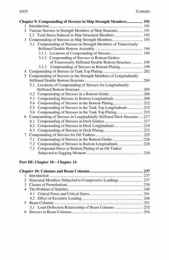
Chapter 9: Compounding of Stresses in Ship Strength Members................ 191 1 Introduction .............................................................................................. 191 2 Various Stresses in Strength Members of Ship Structure ......................... 191 2.1 Total Stress Induced in Ship Structural Members............................. 192 3 Compounding of Stresses in Ship Strength Members............................... 193
3.1 Compounding of Stresses in Strength Members of Transversely Stiffened Double Bottom Assembly ................................................ 194
3.1.1 Locations of Compounding of Stresses ................................ 194 3.1.2 Compounding of Stresses in Bottom Girders
of Transversely Stiffened Double Bottom Structure............ 195 3.1.3 Compounding of Stresses in Bottom Plating....................... 199
4 Compounding of Stresses in Tank Top Plating ........................................ 202 5 Compounding of Stresses in the Strength Members of Longitudinally Stiffened Double Bottom Structure .......................................................... 204
5.1 Locations of Compounding of Stresses for Longitudinally Stiffened Bottom Structure ............................................................... 205
5.2 Compounding of Stresses in a Bottom Girder.................................. 206 5.3 Compounding Stresses in Bottom Longitudinals ............................. 208 5.4 Compounding of Stresses in the Bottom Plating.............................. 212 5.5 Compounding of Stresses in the Tank Top Longitudinals ............... 215 5.6 Compounding of Stresses in the Tank Top Plating .......................... 215
6 Compounding of Stresses in Longitudinally Stiffened Deck Structure .... 217 6.1 Compounding of Stresses in Deck Girders ...................................... 217 6.2 Compounding of Stresses in Deck Longitudinals ............................ 219 6.3 Compounding of Stresses in Deck Plating ....................................... 222
7 Compounding of Stresses for Oil Tankers................................................ 225 7.1 Compounding of Stresses in the Bottom Girder............................... 226 7.2 Compounding of Stresses in Bottom Longitudinals......................... 228 7.3 Compound Stress in Bottom Plating of an Oil Tanker
Subjected to Sagging Moment ......................................................... 230 Part III: Chapter 10 – Chapter 14 Chapter 10: Columns and Beam Columns ..................................................... 237 1 Introduction .............................................................................................. 237 2 Structural Members Subjected to Compressive Loadings ........................ 237 3 Classes of Perturbations............................................................................ 238 4 The Problem of Stability........................................................................... 240
4.1 Critical Force and Critical Stress...................................................... 241 4.2 Effect of Eccentric Loading ............................................................. 248
5 Beam Columns ......................................................................................... 251 5.1 Load-Deflection Relationship of Beam Columns ............................ 252
6 Stresses in Beam Columns........................................................................ 254
Contents XXV
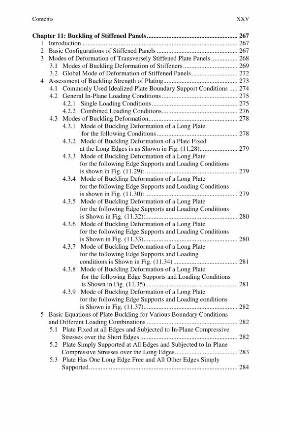
Chapter 11: Buckling of Stiffened Panels....................................................... 267 1 Introduction .............................................................................................. 267 2 Basic Configurations of Stiffened Panels ................................................. 267 3 Modes of Deformation of Transversely Stiffened Plate Panels ................ 268
3.1 Modes of Buckling Deformation of Stiffeners ................................. 269 3.2 Global Mode of Deformation of Stiffened Panels............................ 272
4 Assessment of Buckling Strength of Plating............................................. 273 4.1 Commonly Used Idealized Plate Boundary Support Conditions ..... 274 4.2 General In-Plane Loading Conditions .............................................. 275
4.2.1 Single Loading Conditions .................................................... 275 4.2.2 Combined Loading Conditions.............................................. 276
4.3 Modes of Buckling Deformation...................................................... 278 4.3.1 Mode of Buckling Deformation of a Long Plate
for the following Conditions ................................................. 278 4.3.2 Mode of Buckling Deformation of a Plate Fixed
at the Long Edges is as Shown in Fig. (11,28)....................... 279 4.3.3 Mode of Buckling Deformation of a Long Plate
for the following Edge Supports and Loading Conditions is shown in Fig. (11.29): ........................................................ 279
4.3.4 Mode of Buckling Deformation of a Long Plate for the following Edge Supports and Loading Conditions is shown in Fig. (11.30): ........................................................ 279
4.3.5 Mode of Buckling Deformation of a Long Plate for the following Edge Supports and Loading Conditions is Shown in Fig. (11.32):........................................................ 280
4.3.6 Mode of Buckling Deformation of a Long Plate for the following Edge Supports and Loading Conditions is Shown in Fig. (11.33)......................................................... 280
4.3.7 Mode of Buckling Deformation of a Long Plate for the following Edge Supports and Loading conditions is Shown in Fig. (11.34) ....................................... 281
4.3.8 Mode of Buckling Deformation of a Long Plate for the following Edge Supports and Loading Conditions is Shown in Fig. (11.35)........................................................ 281
4.3.9 Mode of Buckling Deformation of a Long Plate for the following Edge Supports and Loading conditions is Shown in Fig. (11.37)......................................................... 282
5 Basic Equations of Plate Buckling for Various Boundary Conditions and Different Loading Combinations ....................................................... 282
5.1 Plate Fixed at all Edges and Subjected to In-Plane Compressive Stresses over the Short Edges ........................................................... 282
5.2 Plate Simply Supported at All Edges and Subjected to In-Plane Compressive Stresses over the Long Edges...................................... 283
5.3 Plate Has One Long Edge Free and All Other Edges Simply Supported.......................................................................................... 284
XXVI Contents
5.4 Plate has One Long Edge Free and the Other Long Edge Clamped............................................................................................ 285
6 Buckling of Simply Supported Plate under Various in Plane Loading Conditions................................................................................................. 285
6.1 Plate Subjected to Pure Bending Stresses ........................................ 285 6.2 Plate Subjected to Pure Shear Stresses............................................. 286
7 In-Elastic Bucking .................................................................................... 287 7.1 Inelastic Buckling due Shear Loading.............................................. 288
8 Assessment of Buckling Strength of Plating Subjected to Combined Loading..................................................................................................... 288
8.1 Combined Shear and Compressive Stresses on the Short Edges...... 289 8.2 Combined Shear and In-Plane Bending on the Short Edge.............. 290 8.3 Combined In-Plane Bending and Compression................................ 291 8.4 In Plane Compression in Two Orthogonal Directions...................... 292 8.5 Combined Shear, In-Plane Bending and Compression .................... 293
9 Critical Buckling Stress of Plating of Stiffened Panels ............................ 294 9.1 Longitudinally Stiffened Panels ....................................................... 294 9.2 Transversely Stiffened Panels .......................................................... 295
10 Post–buckling Strength of Plating .......................................................... 298 10.1 Ultimate Stress of Simply Supported Plate Panels......................... 300
10.1.1 Long Edges Loaded................................................................... 300 10.1.2 Short Edges Loaded .................................................................. 301
11 Buckling Limit State of Plate Panels ...................................................... 302 11.1 Uncertainty Modeling of Buckling Safety Margin......................... 303
Chapter 12: Assessment of Buckling of Ship Structure ................................ 305 1 Introduction .............................................................................................. 305 2 Ship Strength Members Sustaining Compressive Forces ......................... 305 3 Basic Equations of Buckling of Plate Panels Subjected to Non-uniform In-Plane Compression......................................................... 307
3.1 Idealization of the In-Plane Compressive Loadings.......................... 307 3.2 Critical Buckling Stress..................................................................... 309 3.3 Boundary Conditions......................................................................... 309
3.3.1 Boundary Conditions of Girders ............................................ 309 3.3.2 Boundary Conditions of Plating ............................................. 310
4 Modes of Buckling ................................................................................... 312 4.1 General Modes of Buckling of Girders ............................................ 312 4.2 Modes of Buckling of Face Plates.................................................... 312 4.3 Modes of Buckling of the Web Plate ............................................... 314
5 General Mode of Buckling of Longitudinals ............................................ 314 6 General Mode of Buckling of Plating....................................................... 315 7 Assessment of Buckling of Girders and Longitudinals............................. 316
7.1 Torsion Buckling.............................................................................. 316 7.2 Lateral Buckling of Flanges ............................................................. 318
8 Assessment of Buckling of Deck Girders ................................................. 319 8.1 Assessment of Buckling of the Web Plate ....................................... 319 8.2 Assessment of Buckling of the Face Plate ....................................... 321
Contents XXVII
9 Assessment of Buckling of Longitudinals ................................................ 322 10 Assessment of Buckling of Plating ......................................................... 326
10.1 Buckling of Bottom Plating........................................................... 326 10.2 Buckling of Deck Plating .............................................................. 328 10.3 Buckling of Side Shell Plating ...................................................... 332
10.3.1 Configurations of Side Shell Plate Panels ........................ 332 10.3.2 Induced Stresses in the Side Shell Plating........................ 332 10.3.3 Compounding of Stresses in Side Shell Plate Panels ....... 334 10.3.4 Assessment of Buckling of Side Shell Plating ................. 335
Chapter 13: Control of Buckling Failure of Ship Structure ......................... 339 1 Introduction .............................................................................................. 339 2 Reliability Basis of Ship Structural Safety ............................................... 339 3 Deterioration of Structural Capability with Time ..................................... 342 4 Responsible Authorities for Ensuring Structural Safety ........................... 343 5 Main Causes of Buckling Failure .............................................................. 344 6 Control of Ship Structure Failure by Improving Design........................... 345
6.1 Improving Design of Plate and Tripping Brackets ........................... 345 6.2 Using Symmetrical Face Plates of Girders....................................... 347 6.3 Improving Design of Curved Part of Web Frame Brackets ............. 347 6.4 Improving Design of Plate Panels Loaded by Compressive
Forces............................................................................................... 348 6.5 Improving Design of Plate Panels Loaded by Shear Forces............. 348 6.6 Improving Design of Local Structural Connections......................... 349 6.7 Improving Design of the Connection between the Web Plate
Stiffeners and Longitudinals ............................................................. 349 6.8 Improving Design of Web Plating of Top Wing Tanks ..................... 350 6.9 Improving Design of the Ends of Side Girders in Oil Tankers .......... 350 6.10 Improving Design of Web Plating of Deep Girders ......................... 351
7 Owners Approach for Improving Ship Structure Operational Life and Safety ................................................................................................. 351
7.1 Impact of Corrosion on Strength of Ship Structure Members .......... 352 8 Control of ship Structure Failure by Improving Quality of Ship Fabrication Processes................................................................................ 356
8.1 Control of the Out-of Straightness of Stiffeners/Girders and Plate Panels ............................................................................... 356
8.2 Control of Fabrication Deformations of Ship Structure Members ... 356 8.2.1 Out-of-Straightness ............................................................... 357 8.2.2 Warping of the Whole Section of the Strength Member ....... 358 8.2.3 Warping of Face Plate ........................................................... 358 8.2.4 Lateral Deviations between Centerline of the Web and
Centerline of the Flange......................................................... 358 8.2.5 Inclination of the Web Plate of Section with Respect
to the Attached Plating.......................................................... 359 8.2.6 Deformations and Deviations of Face Plates or Flanges ....... 359 8.2.7 Gap Between Beam and Frame, see fig. (13.40) ................... 360

XXVIII Contents
8.3 Control of Welding Distortions........................................................ 360 8.3.1 Avoiding Over-Welding........................................................ 360 8.3.2 Placing Welds near the Neutral Axis or the Center
of the Part............................................................................... 360 8.3.3 Balancing Welds Around the Neutral Axis ........................... 360 8.3.4 Control of Alignment of Butt and Fillet Welds ..................... 361
9 Improving Control of Corrosion .............................................................. 361
Chapter 14: Problems ....................................................................................... 363
References ......................................................................................................... 377
Index .................................................................................................................. 381
Introduction
A major requirement for any marine structure is to have low initial and operational costs, to be reasonably safe, not to have catastrophic failure nor to have much trouble in service due to frequent minor failures. Safety is concerned not only with the structure itself, but also with external damage that may result as a consequence of failure. Ship structural analysis and design involves the determination of the design loads, defining acceptable criteria and conducting strength assessment. The establishment of acceptable criteria should be based on the accumulated knowledge and expertise from several sources such as owners, builders, classification societies, and researchers. Once the loads and acceptance criteria are defined, the assessment of strength can be carried out.
The development of a satisfactory ship structure involves the determination of the scantlings (sizes) of all its strength members. These scantlings should provide adequate strength to resist the various types of hull girder and local loads imposed on the ship during her operation among sea waves. These loads include longitudinal and transverse bending, torsion, and shear in still-water and among waves and also the static and dynamic loads resulting from the weight of cargo, hydrostatic and hydrodynamic pressures, impact forces and other local loads such as heavy machinery and equipment. Classification societies have developed techniques for calculating the loads on a ship and evaluating the structural integrity of ship hulls.
Ship strength members sustaining compressive forces should have adequate buckling strength to ensure safety against buckling failure. The assessment of buckling strength of bottom structural members is to be carried out when the ship is in hogging condition and for deck structure members when the ship is in sagging condition. For both cases, the compounding of stresses is to be carried out when the secondary and tertiary loadings are inducing compressive stresses. The computational complexity has been greatly simplified and solved with the introduction of rational analysis procedures. These rational procedures include modeling of the complex ship structure, load modeling and application and modeling of boundary conditions. The analysis of structural members aims at checking the strength, stability and rigidity of the preliminarily selected scantlings of the structure. The strength members of ship structure are analyzed on the basis of the theory of the strength of materials and structural mechanics to determine the induced internal stresses under the action of the applied loads. The assessment of buckling of ship strength members should include the web plates and face plates of deck and bottom girders. The assessment of buckling strength of shell plating should cover the various types of induced in-plane loading conditions and the different end support conditions.