Embed Size (px)
Citation preview

Created in COMSOL Multiphysics 5.6
Bu ck l i n g o f a Compo s i t e C y l i n d e r
This model is licensed under the COMSOL Software License Agreement 5.6.All trademarks are the property of their respective owners. See www.comsol.com/trademarks.

Introduction
Buckling is a structural instability that can lead to failure of a component even without initial material failure. Computation of the critical buckling loads and mode shapes can therefore be important from a design viewpoint, even though it has previously been determined that the loading of the component only causes elastic deformations. This applies to components made from laminated composite materials, where elastic properties, ply thicknesses and stacking sequence of a composite laminate will affect buckling loads and mode shapes.
This example illustrates a linear buckling analysis of a composite cylinder under compressive loading and fixed-end conditions. The composite cylinder is made up of eight layers (plies) of a carbon fiber reinforced epoxy material having different fiber orientations. An Equivalent Single Layer (ESL) theory based approach is used for this analysis. The effect of stacking sequence on the critical load factor is analyzed for different types of balanced laminates, such as a symmetric angle-ply laminate and an antisymmetric angle-ply laminate.
Model Definition
The model geometry consists of a composite cylinder with height of 0.4 m and radius of 0.15 m. The bottom end of the cylinder is fixed whereas the top end is free only to translate in the z direction, as shown in Figure 1. In order to perform a linear buckling analysis, a unit compressive load is applied on the top end of the cylinder in the downward direction.
2 | B U C K L I N G O F A C O M P O S I T E C Y L I N D E R

Figure 1: Model geometry of the laminated composite cylinder.
L A M I N A M A T E R I A L P R O P E R T I E S
The composite lamina is assumed to be made of carbon fibers in an epoxy resin. The homogenized orthotropic material properties (Young’s modulus, shear modulus, and Poisson’s ratio) are given in Table 1.
The density of the lamina is taken as 1700 kg/m3.
S T A C K I N G S E Q U E N C E
The composite laminate consists of eight layers where each layer (ply) has a thickness of 0.125 mm. This makes the total thickness of the composite laminate 1 mm. In order to study the effect of a stacking sequence on the buckling behavior of the composite cylinder, four different laminates are compared:
• Layered Material 1: [0/0/45/-45]s (Symmetric angle-ply laminate)
TABLE 1: MATERIAL PROPERTIES OF A LAMINA.
Material property Value
{E1, E2, E3} {134, 9.2, 9.2} GPa
{G12, G23, G13} {4.8, 4.8, 4.8} GPa
{υ12, υ23, υ13} {0.28, 0.28, 0.28}
Compressive load in the z direction
Constrained end (only free to translate in the z direction)
Fixed end
3 | B U C K L I N G O F A C O M P O S I T E C Y L I N D E R

• Layered Material 2: [90/90/45/-45]s (Symmetric angle-ply laminate)
• Layered Material 3: [90/0/90/0]s (Symmetric cross-ply laminate)
• Layered Material 4: [45/45/45/45]as (Antisymmetric angle-ply laminate)
The stacking sequence of each laminate is shown in Figure 2 and their corresponding fiber orientations are given in Table 2.
The fiber orientations are presented with respect to the first axis of the laminate coordinate system as shown in Figure 3.
Figure 2: Stacking sequence of laminated composite cylinder showing fiber orientation in each layer from bottom to top.
Layered Material: [90/90/45/-45]sLayered Material: [0/0/45/-45]s
Layered Material: [90/0/90/0]s Layered Material: [45/45/45/45]as
4 | B U C K L I N G O F A C O M P O S I T E C Y L I N D E R

Figure 3: The laminate coordinate system showing the first principal direction along the cylinder axis.
TABLE 2: STACKING SEQUENCES CONSIDERED.
Layer Number
Fiber orientation in Layered material 1 (°)
Fiber orientation in Layered material 2 (°)
Fiber orientation in Layered material 3 (°)
Fiber orientation in Layered material 4 (°)
1 0 90 90 45
2 0 90 0 45
3 45 45 90 45
4 -45 -45 0 45
5 -45 -45 0 -45
6 45 45 90 -45
7 0 90 0 -45
8 0 90 90 -45
5 | B U C K L I N G O F A C O M P O S I T E C Y L I N D E R

Results and Discussion
Figure 4: First buckling mode shape and its corresponding critical load factor for Layered Material: [0/0/45/-45]_s.
The buckling analysis of a composite laminate with different stacking sequences shows that the critical buckling load and its corresponding mode shape is highly dependent on the stacking sequence of the individual laminae (plies).
For the first two stacking sequences, where the symmetric angle-ply arrangement is used, the first buckling mode is spiral-shaped as shown in Figure 4 and Figure 5. A notable difference between the two is the pitch of the spiraling.
For the third stacking sequence, where the symmetric cross-ply arrangement is used, the buckling mode is diamond-shaped, as shown in Figure 6. Last, for the fourth stacking sequence, in which an antisymmetric angle-ply arrangement is used, the buckling mode shape is axisymmetric, as shown in Figure 7.
TABLE 3: CRITICAL BUCKLING LOAD FOR DIFFERENT LAMINATES.
Stacking sequence Type of laminate Critical buckling load (kN)
Mode shape
[0/0/45/-45]_s Symmetric angle-ply 117.05 Spiral
[90/90/45/-45]_s Symmetric angle-ply 101.86 Spiral
6 | B U C K L I N G O F A C O M P O S I T E C Y L I N D E R

The critical buckling loads for all the stacking sequences are listed in Table 3. The first stacking sequence, where the symmetric angle-ply arrangement is used and in which four out of eight ply angles are zero, has the highest critical load factor. Not surprisingly, the fourth stacking sequence, where an antisymmetric angle-ply arrangement is used, has the lowest critical load factor.
Interestingly, by only changing the stacking sequence from the fourth to the first, the critical buckling load can be increased by a factor of about two in the present model.
Figure 5: First buckling mode shape and its corresponding critical load factor for Layered Material: [90/90/45/-45]_s.
[90/0/90/0]_s Symmetric cross-ply 92.21 Diamond
[45/45/45/45]_as Antisymmetric angle-ply 64.56 Axisymmetric
TABLE 3: CRITICAL BUCKLING LOAD FOR DIFFERENT LAMINATES.
Stacking sequence Type of laminate Critical buckling load (kN)
Mode shape
7 | B U C K L I N G O F A C O M P O S I T E C Y L I N D E R
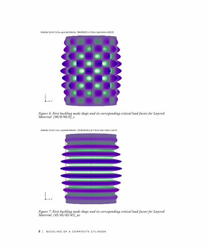
Figure 6: First buckling mode shape and its corresponding critical load factor for Layered Material: [90/0/90/0]_s.
Figure 7: First buckling mode shape and its corresponding critical load factor for Layered Material: [45/45/45/45]_as.
8 | B U C K L I N G O F A C O M P O S I T E C Y L I N D E R

The result of a stationary pre-study, in which the composite cylinder is subjected to the compressive load with fixed end condition, is shown in Figure 8.
Figure 8: von Mises stress distribution in Layered Material: [45/45/45/45]_as.
Notes About the COMSOL Implementation
• In order to perform a buckling analysis, a special Linear Buckling study is used. This consists of a Stationary study step and a Linear Buckling study step. The stationary study step performs the stress analysis for the applied load whereas buckling study uses eigenvalue solver and computes the critical load factors for the applied load.
• In order to run the analysis for various layered materials and compare the results, all the layered materials can be defined using a Switch node in Global Materials. This Switch node can be selected in the Layered Material Link node and a Material Sweep node is added in the study.
• Modeling a composite laminated shell requires a surface geometry (2D), in general called a base surface, and a Layered Material node which adds an extra dimension (1D) to the base surface geometry in the surface normal direction. You can use the Layered
Material functionality to model several layers stacked on top of each other having different thicknesses, material properties, and fiber orientations. You can also optionally
9 | B U C K L I N G O F A C O M P O S I T E C Y L I N D E R

specify the interface materials between the layers and control mesh elements in each layer.
• From a constitutive model point of view, you can either use the Layerwise (LW) theory based Layered Shell interface, or the Equivalent Single Layer (ESL) theory based Layered Linear Elastic Material node in the Shell interface. These interfaces are used in order to apply various loads and constraints on different layers of a composite shell, and to solve for stresses and other relevant variables in each layer of the composite shell.
• The laminated composite shell presented in the current model is modeled using a Layered Linear Elastic Material node in the Shell Interface.
Application Library path: Composite_Materials_Module/Buckling/composite_cylinder_buckling
Modeling Instructions
From the File menu, choose New.
N E W
In the New window, click Model Wizard.
M O D E L W I Z A R D
1 In the Model Wizard window, click 3D.
2 In the Select Physics tree, select Structural Mechanics>Shell (shell).
3 Click Add.
4 Click Study.
5 In the Select Study tree, select Preset Studies for Selected Physics Interfaces>
Linear Buckling.
6 Click Done.
G L O B A L D E F I N I T I O N S
Parameters 11 In the Model Builder window, under Global Definitions click Parameters 1.
2 In the Settings window for Parameters, locate the Parameters section.
10 | B U C K L I N G O F A C O M P O S I T E C Y L I N D E R

3 In the table, enter the following settings:
D E F I N I T I O N S
Variables 11 In the Model Builder window, under Component 1 (comp1) right-click Definitions and
choose Variables.
2 In the Settings window for Variables, locate the Variables section.
3 In the table, enter the following settings:
G E O M E T R Y 1
Cylinder 1 (cyl1)1 In the Geometry toolbar, click Cylinder.
2 In the Settings window for Cylinder, locate the Object Type section.
3 From the Type list, choose Surface.
4 Locate the Size and Shape section. In the Radius text field, type r.
5 In the Height text field, type l.
6 Click Build Selected.
You may want to import material data from a different file and use it while modeling. In the present example, the material properties are loaded from the file composite_cylinder_buckling_material.mph stored in the model’s Application Libraries folder.
M A T E R I A L S
In the Model Builder window, under Component 1 (comp1) right-click Materials and choose Browse Materials.
Name Expression Value Description
r 0.15[m] 0.15 m Cylinder radius
l 0.4[m] 0.4 m Cylinder length
Name Expression Unit Description
Fc shell.LFcrit*1[N] Critical buckling load
un u*nX+v*nY+w*nZ m Normal displacement
11 | B U C K L I N G O F A C O M P O S I T E C Y L I N D E R

M A T E R I A L B R O W S E R
1 In the Material Browser window, click Import Material Library.
2 Browse to the model’s Application Libraries folder and double-click the file composite_cylinder_buckling_material.mph.
3 Click Done.
A D D M A T E R I A L
1 In the Home toolbar, click Add Material to open the Add Material window.
2 Go to the Add Material window.
3 In the tree, select composite cylinder buckling material>Layered Material: [0/0/45/-45]_s.
4 Click Add to Global Materials in the window toolbar.
5 In the Home toolbar, click Add Material to close the Add Material window.
G L O B A L D E F I N I T I O N S
Layered Material: [0/0/45/-45]_s (lmat1)1 In the Settings window for Layered Material, locate the Layer Definition section.
2 Click Layer Stack Preview in the upper-right corner of the section.
12 | B U C K L I N G O F A C O M P O S I T E C Y L I N D E R

Material Switch 1 (sw1)In the Model Builder window, right-click Materials and choose Material Switch.
Drag the Layered Material: [0/0/45/-45]_s node to Material Switch 1 node.
Layered Material: [90/90/45/-45]_s1 In the Model Builder window, under Global Definitions>Materials>Material Switch 1 (sw1)
right-click Layered Material: [0/0/45/-45]_s (sw1.lmat1) and choose Duplicate.
2 In the Settings window for Layered Material, type Layered Material: [90/90/45/-45]_s in the Label text field.
3 Find the Layer Definition section and change the rotation angles in the Rotation column as summarized in the table below.
Layer Rotation
Layer 1 90
Layer 2 90
Layer 3 45
Layer 4 -45
Layer 5 -45
Layer 6 45
Layer 7 90
Layer 8 90
13 | B U C K L I N G O F A C O M P O S I T E C Y L I N D E R

4 Locate the Layer Definition section. Click Layer Stack Preview in the upper-right corner of the section.
Layered Material: [90/0/90/0]_s1 Right-click Layered Material: [90/90/45/-45]_s and choose Duplicate.
2 In the Settings window for Layered Material, type Layered Material: [90/0/90/0]_s in the Label text field.
3 Find the Layer Definition section and change the rotation angles in the Rotation column as summarized in the table below.
Layer Rotation
Layer 1 90
Layer 2 0
Layer 3 90
Layer 4 0
Layer 5 0
Layer 6 90
Layer 7 0
Layer 8 90
14 | B U C K L I N G O F A C O M P O S I T E C Y L I N D E R

4 Locate the Layer Definition section. Click Layer Stack Preview in the upper-right corner of the section.
Layered Material: [45/45/45/45]_as1 Right-click Layered Material: [90/0/90/0]_s and choose Duplicate.
2 In the Settings window for Layered Material, type Layered Material: [45/45/45/45]_as in the Label text field.
3 Find the Layer Definition section and change the rotation angles in the Rotation column as summarized in the table below.
Layer Rotation
Layer 1 45
Layer 2 45
Layer 3 45
Layer 4 45
Layer 5 -45
Layer 6 -45
Layer 7 -45
Layer 8 -45
15 | B U C K L I N G O F A C O M P O S I T E C Y L I N D E R

4 Locate the Layer Definition section. Click Layer Stack Preview in the upper-right corner of the section.
M A T E R I A L S
Layered Material Link 1 (llmat1)In the Model Builder window, under Component 1 (comp1) right-click Materials and choose Layers>Layered Material Link.
S H E L L ( S H E L L )
Layered Linear Elastic Material 11 In the Model Builder window, under Component 1 (comp1) right-click Shell (shell) and
choose Material Models>Layered Linear Elastic Material.
2 In the Settings window for Layered Linear Elastic Material, locate the Boundary Selection section.
3 From the Selection list, choose All boundaries.
4 Locate the Linear Elastic Material section. From the Solid model list, choose Orthotropic.
Fixed Constraint 11 In the Physics toolbar, click Edges and choose Fixed Constraint.
16 | B U C K L I N G O F A C O M P O S I T E C Y L I N D E R
2 Select Edges 2, 3, 7, and 10 only.
Prescribed Displacement/Rotation 11 In the Physics toolbar, click Edges and choose Prescribed Displacement/Rotation.
2 Select Edges 4, 5, 8, and 11 only.
3 In the Settings window for Prescribed Displacement/Rotation, locate the Prescribed Displacement section.
4 Select the Prescribed in x direction check box.
5 Select the Prescribed in y direction check box.
6 Locate the Prescribed Rotation section. From the By list, choose Rotation.
Edge Load 11 In the Physics toolbar, click Edges and choose Edge Load.
2 Select Edges 4, 5, 8, and 11 only.
3 In the Settings window for Edge Load, locate the Force section.
4 From the Load type list, choose Total force.
5 Specify the Ftot vector as
M E S H 1
1 In the Model Builder window, under Component 1 (comp1) click Mesh 1.
2 In the Settings window for Mesh, locate the Physics-Controlled Mesh section.
3 From the Element size list, choose Extra fine.
4 Click Build All.
S T U D Y 1
In the Model Builder window, collapse the Study 1 node.
Material Sweep1 In the Study toolbar, click Material Sweep.
2 In the Settings window for Material Sweep, locate the Study Settings section.
3 Click Add.
4 In the Study toolbar, click Compute.
0 x
0 y
-1[N] z
17 | B U C K L I N G O F A C O M P O S I T E C Y L I N D E R

R E S U L T S
Mode Shape: [0/0/45/-45]_s1 Click the Go to YZ View button in the Graphics toolbar.
2 Click the Zoom Extents button in the Graphics toolbar.
Use the following instructions to plot the first critical buckling mode shape as shown in Figure 4.
3 In the Settings window for 3D Plot Group, type Mode Shape: [0/0/45/-45]_s in the Label text field.
4 Locate the Data section. From the Material Switch 1 list, choose Layered Material: [0/0/45/
-45]_s.
5 Click to expand the Title section. From the Title type list, choose Custom.
6 Find the Type and data subsection. Clear the Unit check box.
7 Clear the Description check box.
8 Clear the Type check box.
Layered Material Slice 11 In the Model Builder window, expand the Mode Shape: [0/0/45/-45]_s node, then click
Layered Material Slice 1.
2 In the Settings window for Layered Material Slice, locate the Expression section.
3 In the Expression text field, type un.
4 In the Mode Shape: [0/0/45/-45]_s toolbar, click Plot.
Follow the instructions below to plot the von Mises stress distribution as shown in Figure 8.
Stress: [45/45/45/45]_as1 In the Model Builder window, right-click Mode Shape: [0/0/45/-45]_s and choose
Duplicate.
2 In the Settings window for 3D Plot Group, type Stress: [45/45/45/45]_as in the Label text field.
3 Locate the Data section. From the Dataset list, choose Study 1/Solution Store 1 (sol2).
4 Locate the Color Legend section. Select the Show legends check box.
5 Locate the Title section. From the Title type list, choose Automatic.
18 | B U C K L I N G O F A C O M P O S I T E C Y L I N D E R

Layered Material Slice 11 In the Model Builder window, expand the Stress: [45/45/45/45]_as node, then click
Layered Material Slice 1.
2 In the Settings window for Layered Material Slice, locate the Expression section.
3 In the Expression text field, type shell.mises.
4 Locate the Through-Thickness Location section. From the Location definition list, choose Reference surface.
5 Locate the Coloring and Style section. From the Color table list, choose RainbowLight.
Follow the instructions below to plot the first critical buckling mode shape as shown in Figure 5.
Mode Shape: [90/90/45/-45]_s1 In the Model Builder window, right-click Mode Shape: [0/0/45/-45]_s and choose
Duplicate.
2 In the Settings window for 3D Plot Group, type Mode Shape: [90/90/45/-45]_s in the Label text field.
3 Locate the Data section. From the Material Switch 1 list, choose Layered Material: [90/90/
45/-45]_s.
Follow the instructions below to plot the first critical buckling mode shape as shown in Figure 6.
Mode Shape: [90/0/90/0]_s1 Right-click Mode Shape: [90/90/45/-45]_s and choose Duplicate.
2 In the Settings window for 3D Plot Group, type Mode Shape: [90/0/90/0]_s in the Label text field.
3 Locate the Data section. From the Material Switch 1 list, choose Layered Material: [90/0/
90/0]_s.
4 In the Mode Shape: [90/0/90/0]_s toolbar, click Plot.
Follow the instructions below to plot the first critical buckling mode shape as shown in Figure 7.
Mode Shape: [45/45/45/45]_as1 Right-click Mode Shape: [90/0/90/0]_s and choose Duplicate.
2 In the Settings window for 3D Plot Group, type Mode Shape: [45/45/45/45]_as in the Label text field.
19 | B U C K L I N G O F A C O M P O S I T E C Y L I N D E R

3 Locate the Data section. From the Material Switch 1 list, choose Layered Material: [45/45/
45/45]_as.
4 In the Mode Shape: [45/45/45/45]_as toolbar, click Plot.
Follow the instructions below to compare the buckling mode shape for all four laminates.
Mode Shape: Comparison1 Right-click Mode Shape: [45/45/45/45]_as and choose Duplicate.
2 In the Settings window for 3D Plot Group, type Mode Shape: Comparison in the Label text field.
3 Locate the Title section. Find the Solution subsection. Clear the Solution check box.
4 Find the Type and data subsection. Select the Type check box.
5 Select the Description check box.
6 Select the Unit check box.
Layered Material Slice 11 In the Model Builder window, expand the Mode Shape: Comparison node, then click
Layered Material Slice 1.
2 In the Settings window for Layered Material Slice, locate the Data section.
3 From the Dataset list, choose Study 1/Parametric Solutions 1 (sol3).
4 From the Material Switch 1 list, choose Layered Material: [0/0/45/-45]_s.
Deformation1 In the Model Builder window, expand the Layered Material Slice 1 node, then click
Deformation.
2 In the Settings window for Deformation, locate the Scale section.
3 Select the Scale factor check box.
4 In the associated text field, type 1.
Layered Material Slice 21 In the Model Builder window, under Results>Mode Shape: Comparison right-click
Layered Material Slice 1 and choose Duplicate.
2 In the Settings window for Layered Material Slice, locate the Data section.
3 From the Material Switch 1 list, choose Layered Material: [90/90/45/-45]_s.
4 Click to expand the Title section. From the Title type list, choose None.
20 | B U C K L I N G O F A C O M P O S I T E C Y L I N D E R

Deformation1 In the Model Builder window, expand the Layered Material Slice 2 node, then click
Deformation.
2 In the Settings window for Deformation, locate the Expression section.
3 In the y component text field, type v+1.3*l.
Layered Material Slice 31 In the Model Builder window, under Results>Mode Shape: Comparison right-click
Layered Material Slice 2 and choose Duplicate.
2 In the Settings window for Layered Material Slice, locate the Data section.
3 From the Material Switch 1 list, choose Layered Material: [90/0/90/0]_s.
Deformation1 In the Model Builder window, expand the Layered Material Slice 3 node, then click
Deformation.
2 In the Settings window for Deformation, locate the Expression section.
3 In the y component text field, type v.
4 In the z component text field, type w+1.3*l.
Layered Material Slice 41 In the Model Builder window, under Results>Mode Shape: Comparison right-click
Layered Material Slice 3 and choose Duplicate.
2 In the Settings window for Layered Material Slice, locate the Data section.
3 From the Material Switch 1 list, choose Layered Material: [45/45/45/45]_as.
Deformation1 In the Model Builder window, expand the Layered Material Slice 4 node, then click
Deformation.
2 In the Settings window for Deformation, locate the Expression section.
3 In the y component text field, type v+1.3*l.
Table Annotation 11 In the Model Builder window, right-click Mode Shape: Comparison and choose
Table Annotation.
2 In the Settings window for Table Annotation, locate the Data section.
3 From the Source list, choose Local table.
21 | B U C K L I N G O F A C O M P O S I T E C Y L I N D E R

4 In the table, enter the following settings:
5 Locate the Coloring and Style section. Clear the Show point check box.
6 From the Anchor point list, choose Lower middle.
Mode Shape: Comparison1 In the Model Builder window, click Mode Shape: Comparison.
2 In the Settings window for 3D Plot Group, locate the Plot Settings section.
3 From the View list, choose New view.
4 Click the Go to YZ View button in the Graphics toolbar.
5 Click the Zoom Extents button in the Graphics toolbar.
6 In the Mode Shape: Comparison toolbar, click Plot.
Use an Evaluation Group instead of Derived Values nodes to compute the critical buckling load.
Critical Buckling Load1 In the Results toolbar, click Evaluation Group.
2 In the Settings window for Evaluation Group, type Critical Buckling Load in the Label text field.
3 Locate the Data section. From the Dataset list, choose Study 1/
Parametric Solutions 1 (sol3).
Global Evaluation 11 Right-click Critical Buckling Load and choose Global Evaluation.
2 In the Settings window for Global Evaluation, locate the Expressions section.
3 In the table, enter the following settings:
4 In the Critical Buckling Load toolbar, click Evaluate.
Enable automatic reevaluation of evaluation groups when the model is re-solved.
x-coordinate y-coordinate z-coordinate Annotation
0 0 -0.15*l [0/0/45/-45]_s
0 1.3*l -0.15*l [90/90/45/-45]_s
0 0 -0.15*l+1.3*l [90/0/90/0]_s
0 1.3*l -0.15*l+1.3*l [45/45/45/45]_as
Expression Unit Description
Fc kN Critical buckling load
22 | B U C K L I N G O F A C O M P O S I T E C Y L I N D E R

5 In the Model Builder window, click Results.
6 In the Settings window for Results, locate the Update of Results section.
7 Select the Reevaluate all evaluation groups after solving check box.
23 | B U C K L I N G O F A C O M P O S I T E C Y L I N D E R

24 | B U C K L I N G O F A C O M P O S I T E C Y L I N D E R