Embed Size (px)
Citation preview

Buckling-Induced Kirigami
Ahmad Rafsanjani1 and Katia Bertoldi1,2,*1John A. Paulson School of Engineering and Applied Sciences, Harvard University, Cambridge, Massachusetts 02138, USA
2Kavli Institute, Harvard University, Cambridge, Massachusetts 02138, USA(Received 3 November 2016; published 21 February 2017)
We investigate the mechanical response of thin sheets perforated with a square array of mutuallyorthogonal cuts, which leaves a network of squares connected by small ligaments. Our combinedanalytical, experimental and numerical results indicate that under uniaxial tension the ligaments buckle outof plane, inducing the formation of 3D patterns whose morphology is controlled by the load direction. Wealso find that by largely stretching the buckled perforated sheets, plastic strains develop in the ligaments.This gives rise to the formation of kirigami sheets comprising periodic distribution of cuts and permanentfolds. As such, the proposed buckling-induced pop-up strategy points to a simple route for manufacturingcomplex morphable structures out of flat perforated sheets.
DOI: 10.1103/PhysRevLett.118.084301
In recent years, origami [1–9] and kirigami [10–27]have become emergent tools to design programmableand reconfigurable mechanical metamaterials. Origami-inspired metamaterials are created by folding thin sheetsalong predefined creases, whereas kirigami allows thepractitioner to exploit cuts in addition to folds to achievelarge deformations and create 3D objects from a flat sheet.Therefore, kirigami principles have been exploited todesign highly stretchable devices [18–24] and morphablestructures [25–27]. Interestingly, several of these studiesalso show that precreased folds are not necessary to formcomplex 3D patterns, as mechanical instabilities in flatsheets with an embedded array of cuts can result in out-of-plane deformation [19–26]. However, while a wide range of3D architectures have been realized by triggering bucklingunder compressive stresses [25,26], instability-inducedkirigami designs subjected to tensile loading are limitedto a single incision pattern comprised of parallel cuts in acentered rectangular arrangement [19–23].In this Letter, we investigate the tensile response of
elastic sheets of thickness t perforated with a squarearray of mutually orthogonal cuts. This perforation patternintroduces a network of square domains of edge l separatedby hinges of width δ [Fig. 1(a)]. While the planar responseof such perforated sheets in the thick limit (i.e., for largevalues of t=δ) has received significant attention, as it ischaracterized by effective negative Poisson’s ratio [28–36][Fig. 1(b)], here we add another dimension and study howthe behavior of the system evolves when the thickness isprogressively decreased (i.e., for decreasing values of t=δ).Our combined analytical, numerical, and experimentalresults indicate that in sufficiently thin sheets mechanicalinstabilities triggered under uniaxial tension can beexploited to create complex 3D patterns and even to guidethe formation of permanent folds. We also find that themorphology of the instability-induced patterns is strongly
affected by the loading direction [see Figs. 1(c) and 1(d)and movies 1 in the Supplemental Material [37]), pointingto an effective strategy to realize functional surfacescharacterized by a variety of architectures.We start by experimentally investigating the effect of the
sheet thickness t and hinge width δ on the response ofthe system subjected to uniaxial tension along the squarediagonals [i.e. for γ ¼ 45°—Fig. 1(c)]. Specimens arefabricated by laser cutting an array of 3 × 8 mutuallyperpendicular cuts [see Fig. 2(b)] into plastic sheets (ArtusCorporation, NJ) with Young’s modulus E ¼ 4.33 GPaand Poisson’s ratio ν≃ 0.4 (see Supplemental Material:
(a)
(b)
(c) (d)
FIG. 1. (a) Schematic of the system: an elastic sheet ofthickness t perforated with a square array of mutually orthogonalcuts. (b) In the thick limit (i.e., for large values of t=δ) theperforated sheet deforms in plane and identically to a network ofrotating squares [28]. (c)–(d) For sufficiently small values of t=δmechanical instabilities triggered under uniaxial tension resultin the formation of complex 3D patterns, which are affected bythe loading direction. The 3D patterns obtained for γ ¼ 45° andγ ¼ 0° are shown in (c) and (d), respectively. Scale bars: 6 mm.
PRL 118, 084301 (2017) P HY S I CA L R EV I EW LE T T ER Sweek ending
24 FEBRUARY 2017
0031-9007=17=118(8)=084301(5) 084301-1 © 2017 American Physical Society

Experiments [37]). In Fig. 2(a), we report the experimentalstress-strain responses for 10 samples characterizedby different values of normalized thickness t=δ andnormalized hinge width δ=l.First, it is apparent that the initial response for all
samples is linear. At this stage, all hinges bend in-plane,inducing pronounced rotations of the square domains[Fig. 1(b)], which result in large negative values of themacroscopic Poisson’s ratio [29,30]. As such, the stiffnessof the perforated sheets, E, is governed by the in-planeflexural deformation of the hinges and it can be shown that(see Supplemental Material: Analytical Exploration [37])
E ¼ σxεx
¼ 2
3E
�δ
l
�2
: ð1Þ
Second, for the thin samples (i.e., t=δ ≪ 1), the curvesreported in Fig. 2(a) also show a sudden departure fromlinearity to a plateau stress caused by the out-of-planebuckling of the hinges. Such buckling in turn induces out-of-plane rotations of both the square domains and the cuts,which arrange to form a 3D pattern reminiscent of amisaligned Miura-ori [38] with an alternation of squaresolid faces (corresponding to the square domains) andrhombic open ones (defined by the cuts) [see Fig. 1(c),Fig. 2(b) at εx ¼ 0.12 and movie 2 in the SupplementalMaterial [37]]. To characterize the critical strain, εc, atwhich the instability is triggered, we start by noting thatsince the stress immediately after instability is almostconstant, the contribution of out-of-plane strain energyUo should be linear in εx, (see Supplemental Material:Analytical Exploration [37])
UoðεxÞ ¼ Eεcðεx − εcÞ: ð2Þ
Moreover, assuming that the square domains remain rigidand that the deformation localizes at the hinges which canbe modeled as flexural beam segments, Uo can also bewritten as
UoðεxÞ ¼ 81
8l2t
Zδ
0
EIoρ2o
ds ¼ 1
3E
�tl
�2
θ2o; ð3Þ
where Io ¼ δt3=12, ρo ¼ δ=2θo, and 2θo is the openingangle of each cut after out-of-plane buckling, which forγ ¼ 450 is approximated by
θ2o ≃ εx − εc: ð4ÞFinally, by equating Eqs. (2) and (3) we find that
εc ≃ 1
2
�tδ
�2
; ð5Þ
which despite the simplifications made, compares very wellwith our experimental results [Fig. 2(c)] and numericalsimulations [Fig. S6]. Note that a similar expression for thecritical strain has been previously obtained for kirigamipatterns comprising parallel cuts in a centered rectangulararrangement [23].Third, for large enough values of the applied strain εx,
the stress σx rises sharply again. This regime starts whenthe square domains align [Fig. 2(b) at εx ¼ 0.24] and thedeformation mechanism of the hinges switches frombending dominated to stretching dominated. At this stage,localized zones of intense strain (of plastic nature) developin the hinges and result in the formation of permanentfolds. Although we start with a flat elastic sheet with anembedded array of cuts (i.e., a perforated sheet), by largelystretching it we form a system that comprises a periodicdistribution of both cuts and folds (i.e., a kirigami sheet).In particular, we note that our kirigami sheets possessseveral deformation characteristics of the Miura-ori [2,3]and zigzag-base folded kirigami [12,13] (see movie 3 inSupplemental Material [37]), as (i) they are flat foldable[Fig. 3(a)], (ii) they form a saddle shape with a negativeGaussian curvature upon nonplanar bending [Fig. 3(b)],and (iii) they can be twisted under antisymmetric out-of-plane deformation, [Fig. 3(c)]. However, in contrast to the
(a)
0 0.05 0.1 0.15 0.2 0.250
0.01
0.02
0.03
0.04
0.05(c)(b)
(0.06, 0.085)(0.06, 0.125)(0.06, 0.210)(0.10, 0.051)(0.10, 0.076)(0.10, 0.127)(0.14, 0.036)(0.14, 0.054)(0.14, 0.091)(0.10, 0.508)
0 0.01 0.02 0.03 0.04 0.050
0.005
0.01
0.015
0.02
0.025
FIG. 2. (a) Experimental stress-strain curves for perforated sheets characterized by different normalized hinge width δ=l andnormalized sheet thickness t=δ for γ ¼ 45°. Note that the stress is normalized by the effective in-plane Young’s modulusE ¼ 2=3Eðδ=lÞ2. (b) Snapshots of the sample with δ=l ¼ 0.06 and t=δ≃ 0.085 at εx ¼ 0, 0.12, and 0.24. (c) Critical strain εc asa function of ðt=δÞ2 as obtained from experiments (markers) and predicted analytically (dashed line).
PRL 118, 084301 (2017) P HY S I CA L R EV I EW LE T T ER Sweek ending
24 FEBRUARY 2017
084301-2

Miura-ori, misaligned Miura-ori and zigzag-base foldedkirigami, the macroscopic Poisson’s ratio of our kirigamisheets is positive (see movie 4 in the Supplemental Material[37]). This is the result of the fact that not all the faces arerigid. As such, the applied tensile deformation not onlyresults in the rotation of the faces about the connectingridges, but also in the deformation of those defined by the
cuts, allowing lateral contraction of the structure. It is alsonoteworthy that, differently from the misaligned Miura-orithat can only be folded to a plane, the additional degreeof freedom provided by the open cuts allow the Miurakirigami to be laterally flat foldable [movie 4]. Finally, wenote that our Miura kirigami structures have higher bendingrigidity than the corresponding flat perforated sheet [seeFig. 3(d) and Movie 3 in Supplemental Material [37]].Having determined that instabilities in thin sheets with
an embedded array of mutually perpendicular cuts can beharnessed to form complex 3D patterns, we further explorethe design space using finite element (FE) analyses (SeeSupplemental Material: FE Simulations [37]). We startby numerically investigating the response of finite sizesamples stretched along the square diagonals (i.e., γ ¼ 45°)and find excellent agreement with the experimental results(Fig. S5 and Movie 2 in the Supplemental Material [37]).This validates the numerical analyses and indicates thatthey can be effectively used to explore the response of thesystem. First, we use the simulations to understand howplastic deformation evolves. By monitoring the distributionof the von Mises stress within the sheets, we find thatplastic deformation initiates at the tip of hinges well afterthe buckling onset [see Figs. S6 and S9] and then graduallyexpand to fully cover the hinges when the sample is fullystretched and the deformation mechanism changes frombending dominated to stretching dominated. Second, wenumerically explore the effect of different loading con-ditions and find that uniaxial tension is the ideal one to
(a) (b)
(c) (d)
FIG. 3. The buckling-induced Miura kirigami sheet (a) is flatfoldable, (b) forms a saddle shape with a negative Gaussiancurvature upon nonplanar bending, (c) twists under antisymmet-ric out-of-plane deformation, and (d) has much higher bendingrigidity than the corresponding flat perforated sheet (inset). Notethat the 127 μm thick Miura kirigami sheet shown here supports a20 g weight.
(b)(a)
0 0.05 0.1 0.15 0.2 0.250
0.01
0.02
0.03
0.04
0.05
0 0.05 0.1 0.15 0.2 0.25
-1
-0.5
0
0.5
1
(d)
(c)
0 0.05 0.1 0.15 0.20
10
20
30
40
50
0.25
FIG. 4. Effect of loading direction γ on the mechanical response of the perforated sheets. Evolution of the (a) normalized stress σx=E,(b) the in-plane macroscopic Poisson’s ratio νyx and (c) the opening angle of cuts 2θo1 and 2θo2 as a function of the applied strain εx fordifferent values of γ. Note that νyx is negative only for εx < εc (as at this stage the deformation of the structure is purely planar andidentical to that of a network of rotating squares) and that it increases sharply and reaches positive values once the instability is triggered.(d) Numerical snapshots of 3D patterns obtained at εx ¼ 0.125 for different values of γ. The contours shows the normalized out-of-planedisplacements.
PRL 118, 084301 (2017) P HY S I CA L R EV I EW LE T T ER Sweek ending
24 FEBRUARY 2017
084301-3

trigger the formation of well-organized out-of-planepatterns in our perforated sheets [see Fig. S7]. Third, weinvestigate the effect of the loading direction by simulatingthe response of periodic unit cells. In Fig. 4(a) we report thestress-strain responses obtained numerically for perforatedsheets characterized by t=δ ¼ 0.127 and δ=l ¼ 0.04 loadeduniaxially for γ ¼ 0°, 15°, 30°, and 45°. Our results indicatethat the mechanical response of the perforated sheets underuniaxial tension is minimally affected by the loading direc-tion. In fact, the evolution of both stress [Fig. 4(a)] andmacroscopic in-plane Poisson’s ratio [Fig. 4(b)] are similarfor different values of γ. By contrast, we find that themorphology of the 3D patterns induced by the instabilityis significantly affected by γ [Figs. 4(c) and 4(d)].As the loading directions varies from γ ¼ 45° to γ ¼ 0°,the symmetry in the opening angle of the two sets ofperpendicular cuts breaks. While for γ ¼ 45° all cuts openequally (i.e., θo1 ¼ θo2), as we reduce γ, one set becomeswider (i.e., θo1 monotonically increases) and the otherprogressively narrower (i.e., θo2 monotonically decreases)[Fig. 4(c)]. In the limit case of γ ¼ 0° one set of cuts remainsalmost closed and a 3D cubic pattern emerges after buckling[Fig. 1(d), movie 5]. Furthermore, permanent folds withdirection controlled by γ can be introduced by largelystretching the perforated sheets. As such, by controllingthe loading direction a variety of kirigami sheets can beformed [movie 6].While all of themare laterally flat foldable,we find that by increasing γ from 0° to 45° the resultingkirigami sheets have higher bending rigidity and theirGaussian curvature varies from zero (for γ ¼ 0°) to largenegative values (for γ ¼ 45°). Furthermore, by increasing γ,the resulting kirigami sheets become more compliant undertorsion (movie 6 in the Supplemental Material [37]).In summary, our combined experimental, analytical,
and numerical study indicates that buckling in thin sheetsperforated with a square array of cuts and subjected touniaxial tension can be exploited to form 3D patterns andeven create periodic arrangements of permanent folds.While buckling phenomena in cracked thin plates subjectedto tension have traditionally been regarded as a routetoward failure [39], we show that they can also be exploitedto transform flat perforated sheets to kirigami surfaces.Our buckling-induced strategy not only provides a simpleroute for manufacturing kirigami sheets, but can also becombined with optimization techniques to design perfo-rated patterns capable of generating desired complex 3Dsurfaces under external loading [9,11,40]. Finally, since theresponse of our perforated sheets is essentially scale-free,the proposed pop-up strategy can be used to fabricatekirigami sheets over a wide range of scales, from trans-formable meter-scale architectures to tunable nanoscalesurfaces [24,41].
K. B. acknowledges support from the NationalScience Foundation under Grant No. DMR-1420570 andCMMI-1149456. A. R. also acknowledges the financial
support provided by Swiss National Science Foundation(SNSF) under Grant No. 164648. The authors thank BoleiDeng for fruitful discussions, Yuerou Zhang for assistancein laser cutting, and Matheus Fernandes for proofreadingthe manuscript.
*Corresponding [email protected]
[1] L. Mahadevan and S. Rica, Science 307, 1740 (2005).[2] M. Schenk and S. D. Guest, Proc. Natl. Acad. Sci. U.S.A.
110, 3276 (2013).[3] Z. Y. Wei, Z. V. Guo, L. Dudte, H. Y. Liang, and L.
Mahadevan, Phys. Rev. Lett. 110, 215501 (2013).[4] T. Tachi, J. Mec. Des. 135, 111006 (2013).[5] J. L. Silverberg, A. A. Evans, L. McLeod, R. C. Hayward,
T. Hull, C. D. Santangelo, and I. Cohen, Science 345, 647(2014).
[6] H. Yasuda and J. Yang, Phys. Rev. Lett. 114, 185502 (2015).[7] J. L. Silverberg, J-H. Na, A. A. Evans, B. Liu, T. C. Hull,
C. D. Santangelo, R. J. Lang, R. C. Hayward, and I. Cohen,Nat. Mater. 14, 389 (2015).
[8] J. T. B. Overvelde, T. A. de Jong, Y. Shevchenko, S. A.Becerra, G. M. Whitesides, J. C. Weaver, C. Hoberman, andK. Bertoldi, Nat. Commun. 7, 10929 (2016).
[9] L. H. Dudte, E. Vouga, T. Tachi, and L. Mahadevan,Nat. Mater. 15, 583 (2016).
[10] T. Castle, Y. Cho, X. Gong, E. Jung, D. M. Sussman, S.Yang, and R. D. Kamien, Phys. Rev. Lett. 113, 245502(2014).
[11] D. M. Sussman, Y. Cho, T. Castle, X. Gong, E. Jung, S.Yang, and R. D. Kamien, Proc. Natl. Acad. Sci. U.S.A. 112,7449 (2015).
[12] M. Eidini and G. H. Paulino, Sci. Adv. 1, e1500224 (2015).[13] M. Eidini, Ext. Mech. Lett. 6, 96 (2016).[14] T. Castle, D. M. Sussman, M. Tanis, and R. D. Kamien,
Sci. Adv. 2, e1601258 (2016).[15] B. G. Chen, B. Liu, A. A. Evans, J. Paulose, I. Cohen, V.
Vitelli, and C. D. Santangelo, Phys. Rev. Lett. 116, 135501(2016).
[16] Y. Tang and J. Yin, Ext. Mech. Lett., DOI: 10.1016/j.eml.2016.07.005.
[17] K. A. Seffen, Phys. Rev. E 94, 033003 (2016).[18] Z. Song, X. Wang, C. Lv, Y. An, M. Liang, T. Ma, D. He,
Y-J. Zheng, S-Q. Huang, H. Yu, and H. Jiang, Sci. Rep. 5,10988 (2015).
[19] T. C. Shyu, P. F. Damasceno, P. M. Dodd, A. Lamoureux,L. Xu, M. Shlian, M. Shtein, S. C. Glotzer, and N. A. Kotov,Nat. Mater. 14, 785 (2015).
[20] M. K. Blees, A.W. Barnard, P. A. Rose, S. P. Roberts, K. L.McGill, P. Y. Huang, A. R. Ruyack, J. W. Kevek, B. Kobrin,D. A. Muller, and P. L. McEuen, Nature (London) 524, 204(2015).
[21] A. Lamoureux, K. Lee, M. Shlian, S. R. Forrest, and M.Shtein, Nat. Commun. 6, 8092 (2015).
[22] D. Norman, V&A Conserv. J. 9, 10 (1999).[23] M. Isobe and K. Okumura, Sci. Rep. 6, 24758 (2016).[24] C. Wu, X. Wang, L. Lin, H. Guo, and Z. L. Wang, ACS
Nano 10, 4652 (2016).
PRL 118, 084301 (2017) P HY S I CA L R EV I EW LE T T ER Sweek ending
24 FEBRUARY 2017
084301-4

[25] Y. Zhang, Z. Yan, K. Nan, D. Xiao, Y. Liu, H. Luan, H. Fu, X.Wang, Q. Yang, J. Wang, W. Ren, H. Si, F. Liu, L. Yang, H.Li, J. Wang, X. Guo, H. Luo, L. Wang, Y. Huang, and J. A.Rogers, Proc. Natl. Acad. Sci. U.S.A. 112, 11757 (2015).
[26] Z. Yan, F. Zhang, J. Wang, F. Liu, X. Guo, K. Nan, Q. Lin,M. Gao, D. Xiao, Y. Shi, Y. Qiu, H. Luan, J. H. Kim, Y.Wang, H. Luo, M. Han, Y. Huang, Y. Zhang, and J. A.Rogers, Adv. Funct. Mater. 26, 2629 (2016).
[27] R. M. Neville, F. Scarpa, and Alberto Pirrera, Sci. Rep. 6,31067 (2016).
[28] J. N. Grima and K. E. Evans, J. Mater. Sci. Lett. 19, 1563(2000).
[29] A. A. Vasiliev, S. V. Dmitriev, Y. Ishibashi, and T. Shigenari,Phys. Rev. B 65, 094101 (2002).
[30] J. N. Grima, A. Alderson, and K. E. Evans, Phys. StatusSolidi B 242, 561 (2005).
[31] S. Shan, S. H. Kang, Z. Zhao, L. Fang, and K. Bertoldi, Ext.Mech. Lett. 4, 96 (2015).
[32] Y. Cho, J.-H. Shin, A. Costa, T. A. Kim, V. Kunin, J. Li,S. Yeon Lee, S. Yang, H. N. Han, I.-S. Choi, and D. J.Srolovitz, Proc. Natl. Acad. Sci. U.S.A. 111, 17390 (2014).
[33] R. Gatt, L. Mizzi, J. I. Azzopardi, K. M. Azzopardi, D.Attard, A. Casha, J. Briffa, and J. N. Grima, Sci. Rep. 5,8395 (2015).
[34] Y. Suzuki, G. Cardone, D. Restrepo, P. D. Zavattieri, T. S.Baker, and A. F. Tezcan, Nature (London) 533, 369 (2016).
[35] J. N. Grima, E. Manicaro, and D. Attard, Proc. R. Soc. A467, 439 (2011).
[36] A. Rafsanjani and D. Pasini, Ext. Mech. Lett. 9, 291 (2016).[37] See Supplemental Material at http://link.aps.org/
supplemental/10.1103/PhysRevLett.118.084301 which in-cludes Refs. [28–30], supporting movies, an analyticalexploration, details of the FE simulations, and a descriptionof the experiments.
[38] K. Saito, A. Tsukahara, and Y. Okabe, Proc. R. Soc. A 472,20150235 (2016).
[39] G. F. Zielsdorff and R. L. Carlson, Eng. Fract. Mech. 4, 939(1972).
[40] M. Konaković, K. Crane, B. Deng, S. Bouaziz, D. Piker,and M. Pauly, ACM Trans. Graph. 35, 89 (2016).
[41] F. Cavallo, Y. Huang, E. W. Dent, J. C. Williams, and M. G.Lagally, ACS Nano 8, 12219 (2014).
PRL 118, 084301 (2017) P HY S I CA L R EV I EW LE T T ER Sweek ending
24 FEBRUARY 2017
084301-5

SUPPLEMENTAL MATERIALS
Buckling-induced kirigami
Ahmad Rafsanjani1 and Katia Bertoldi1,2∗
1John A. Paulson School of Engineering and Applied Sciences,
Harvard University, Cambridge, MA 02138, USA and
2Kavli Institute, Harvard University, Cambridge, MA 02138, USA
(Dated: January 26, 2017)
∗Correspondence to [email protected]
1

I. ANALYTICAL EXPLORATION
To get a deeper understanding of the mechanical response of the considered patterned
sheets, we analytically investigate their behavior. We first study the initial in-plane linear
elastic response of the system and then characterize the onset of instability resulting in the
formation of 3D patterns. In all our calculations we assume that all deformation is localized
at the hinges and that the square domains are rigid.
Initial in-plane linear elastic response. The stress-strain curves shown in Fig. 2a of
the main text show that the response of all samples is initially linear. Here, we derive an
analytical relation for the effective Young’s modulus of the perforated sheets, E, in terms of
the geometrical parameters l and δ, and the Young’s modulus of the sheet E.
We focus on a unit cell comprising four square domains [Fig. S1(a)] and deform it
uniaxially along one set of cuts (i.e. γ = 0◦) by applying a macroscopic stress σx = f/(2lt),
where f is the force applied to the hinges on the vertical boundaries and 2lt denotes its cross
sectional area [Fig. S1(b)]. It is important to note that using standard axis transformation
techniques it has been shown that the planar response of such perforated sheets is not
affected by the loading direction γ [2, 3]. Therefore, although here for the sake of simplicity
we consider γ = 0◦, we expect E to be identical for any loading direction (i.e. for any value
of γ).
The applied uniaxial stress generates identical bending moments M at all hinges, which
in turn induce the rotation of all square domains by an angle θi and the opening of the all
(a) (b) (c)
FIG. S1: (a) Schematic of the system in the undeformed configuration: an elastic sheet of thickness
t perforated with a square array of mutually orthogonal cuts. (b) Schematic of the system in the
planarly deformed configuration (c) Free body diagram of a square domain.
2

cuts by an angle 2θi [Fig. S1(b)]. Focusing on a single square domain [Fig. S1(c)], it is easy
to see that:
M =1
4× fl
2=
1
4σxl
2t. (S1)
Moreover, since M must be balanced by the couple induced by the internal loads, we have:
M =EIiρi, (S2)
where Ii = δ3t/12 is the second moment of area of each hinge about the z-axis and ρi denotes
the curvature of each bent hinge. Assuming that the length of the bent region of the hinge
is approximately equal to the hinge width δ, we obtain:
ρi 'δ
2θi(S3)
Substitution of Eqs. (S1) and (S3) into Eq. (S2) yields:
σx =2
3E
(δ
l
)2
θi (S4)
Moreover, since the strain in the loading direction is given by:
εx = cos θi + sin θi − 1, (S5)
in the small deformation regime (i.e. θi → 0) we have:
εx ' θi, (S6)
so that
σx =2
3E
(δ
l
)2
εx (S7)
It follows that the effective Young’s modulus of perforated sheet, E, is:
E =σxεx
=2
3E
(δ
l
)2
. (S8)
Finally, we note that considering each hinge as a beam of thickness δ and width t, its
strain energy density under in-plane deformation can be calculated as:
Uhinge =1
2V
∫ δ
0
EIiρ2i
ds =1
16Eε2x (S9)
where V = 4l2t is the volume of the unit cell. The in-plane strain energy density of a unit
cell comprising eight hinges is then given by:
Ui = 8× Uhinge =1
2Eε2x (S10)
3
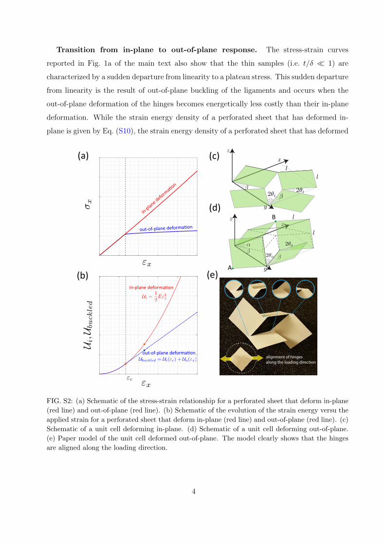
Transition from in-plane to out-of-plane response. The stress-strain curves
reported in Fig. 1a of the main text also show that the thin samples (i.e. t/δ � 1) are
characterized by a sudden departure from linearity to a plateau stress. This sudden departure
from linearity is the result of out-of-plane buckling of the ligaments and occurs when the
out-of-plane deformation of the hinges becomes energetically less costly than their in-plane
deformation. While the strain energy density of a perforated sheet that has deformed in-
plane is given by Eq. (S10), the strain energy density of a perforated sheet that has deformed
alignment of hinges
along the loading direction
in-p
lane d
eform
a�on
out-of-plane deforma�on
in-plane deforma�on
out-of-plane deforma�on
(b)
(c)
(d)
(a)
(e)A
B
FIG. S2: (a) Schematic of the stress-strain relationship for a perforated sheet that deform in-plane
(red line) and out-of-plane (red line). (b) Schematic of the evolution of the strain energy versu the
applied strain for a perforated sheet that deform in-plane (red line) and out-of-plane (red line). (c)
Schematic of a unit cell deforming in-plane. (d) Schematic of a unit cell deforming out-of-plane.
(e) Paper model of the unit cell deformed out-of-plane. The model clearly shows that the hinges
are aligned along the loading direction.
4

out-of plane can be expressed as:
Ubuckled(εx) = Ui(εc) + Uo(εx) (S11)
where εc is the critical strain at which buckling occurs and Uo is energy contribution due to
the out-of-plane deformation.
Since σx = dUbuckled/dεx and the stress immediately after instability is almost constant
[Fig. S2(b)], it follows that Uo(εx) is approximately linear in εx [Fig. S2(a)] and can be
identified as the tangent of Ui(εx) at εc:
Uo(εx) = Eεc(εx − εc) (S12)
Moreover, as all hinges bend out-of-plane, Uo(εx) can also be expressed as:
Uo(εx) = 4× 1
2V
∫ δ
0
EIoρ2o1
ds+ 4× 1
2V
∫ δ
0
EIoρ2o2
ds =1
6E
(t
l
)2
(θ2o1 + θ2o2) (S13)
where Io = δt3/12 is the second moment of area with respect to x-axis (y-axis) for hinges
along y-axis (x-axis), ρoj = δ/(2θoj) is the out-of-plane curvature of the deformed hinges and
2θoj is the opening angle of an hinge after out-of-plane buckling. Note that, in general, after
buckling the opening angles of the hinges within the perforate sheet can take two values,
2θo1 and 2θo2 (i.e. not all hinges open equally after buckling).
While Eq. (S13) is valid for any loading direction, for γ = 45o (i.e. loading along the
square diagonals) θo1 = θo2 = θo, so that Eq. (S13) simplifies to:
Uo(εx) = 8× 1
2V
∫ δ
0
EIoρ2o
ds =1
3E
(t
l
)2
θ2o. (S14)
The critical strain εc can then be determined by equation Eqs. (S12) and (S14) after having
expressed θo as a function of εx. To this end, we first note that for γ = 45o [Fig. S2(d)]
cos 2θo = cosα sin 2β (S15)
where α ∈ [0, π/2] determines the orientation of the square domains with respect to xy-plane
and
β = arccos1 + εx√
2. (S16)
is the angle between the edge of the square domain placed on the xy-plane and the x-axis.
5

Moreover, since the experiments indicate that for γ = 45◦ the hinges are approximately
aligned along the loading direction [see paper illustration in Fig. S2(e)], the distance between
points A and B shown in Fig. S2(d) remains constant (i.e. |AB| =√
5l) and
cosα = tan β. (S17)
While Eq. (S17) is exact well into the postbuckling regime, it does not correctly capture
the response of the system at the onset of instability, as it predicts α 6= 0 for εc (i.e. it
predicts that the square are already rotated out of the xy-plane when the instability is
triggered). To correct for this, we modify Eq. (S17) as
cosα ' tan(β + θc), for εx ≥ εc. (S18)
where θc = π/4−βc denotes the opening angle associated to εc. Note that, according to Eq.
(S18), α = 0 at εc Substitution of Eqs. (S16) and (S18) into Eq. (S15) yields:
θo(εx) =1
2arccos
[sin
(2 arccos
1 + εx√2
)tan
(π
4+ arccos
1 + εx√2− arccos
1 + εc√2
)](S19)
Although Eq. (S19) provides a highly non-linear relation between θo and εx, close to the
instability point θ2o(εx) can be approximated as
θ2o(εx) ' εx − εc (S20)
and can be then inserted into Eq. (S11) to express Uo in terms of εx. Finally, the critical
strain εc can be determined by substituting Eq. (S20) into Eq. (S14) and then equating it
to Eq. (S12):
εc '1
2
(t
δ
)2
(S21)
This relation shows that the critical strain scales quadratically with t/δ and despite
several simplifications made, it compares very well with both experimental [Fig. 2(c)] and
numerical [Fig. S8] results.
II. EXPERIMENTS
Fabrication Specimens are fabricated by laser cutting an array of 3 × 8 mutually
perpendicular cuts into plastic sheets (Artus Corporation, NJ). Total number of 10 samples
6

0 0.02 0.04 0.06 0.080
25
50
75
100
FIG. S3: Stress-strain curves of the plastic sheets obtained by stretching them uniaxially. The
sheets with t = 50.8, 76.2 and 127µm are made of polyester, while the one with t = 508µm is made
of PETG.
εp 0 0.002 0.004 0.006 0.008 0.018 0.028
σ (MPa) 66.4 75.78 80.52 82.75 84.45 88.09 89.06
TABLE S1: Plastic strain (εp) versus stress (σ) for the three polyester sheets.
are fabricated with a combination of different sheet thickness (t = 50.8µm, 76.2µm, 127µm
and 508µm) and three normalized hinge widths (δ/l = 0.06, 0.1, 0.14). Note that in all
our samples l = 10mm. The material properties of the plastic sheets used in this study
are characterized by performing uniaxial tensile tests (ASTM D882) with a uniaxial testing
machine (Instron 5566) equipped with a 100N load cell. Strips with a width of 10 mm and
gauge length of 120 mm are fully clamped at both ends using a pneumatic gripper and
stretched with a displacement rate of 0.1 mm/s up to ε = 0.8 [Fig. S3]. The stress-strain
curves reported in Fig. S3 indicate that the polyester sheets with thickness t = 50.8µm
(red line), 76.2µm (green line), 127µm (blue line) are characterized by a Young’s modulus
E = 4.33 GPa. Moreover, their 0.2% offset yield strength is measured as σy = 66.4 MPa
and their plastic strain εp versus σ is reported in the Table S1 up to fully plastic region.
Differently, for the thick PETG sheet (t = 508µm, yellow line) we measure a Young’s
modulus E = 1.75 GPa. Finally, we note that for all the plastic sheets a typical Poisson’s
ratio ν = 0.4 is assumed.
7

kirigami
sample
pneuma�c
gripper
load cell
pneuma�c
gripper
(a) (b)
FIG. S4: (a) Experiment setup and (b) closeup view of the perforated sheet.
Testing. The quasi-static uniaxial tensile response of the perforated sheets comprised
of 3× 8 unit cells was probed by using a uniaxial testing machine (Instron 5566) equipped
with a 10N load cell. All test were conducted under displacement rate of ux = 0.1 mm/s
[Fig. S4].
III. FINITE ELEMENT SIMULATIONS
In this Section, we provide details about the Finite Element (FE) simulations conducted
for this study using the commercial package Abaqus\Standard 6.12 (Dassault Systemes). In
all simulations, the models are discretized with 3D shell elements (S4R) and the cuts in flat
sheets are modeled as seam cracks with duplicate overlapping nodes along the cuts.
Finite size simulations. To validate the FE simulations, we first performed finite size
simulations on perforated sheets similar to those used in experiments comprising an array of
3× 8 cells. The lower boundary of the sample is fixed and a vertical displacement is applied
to the upper boundary while the lateral boundaries are assumed to be traction free. The
material behavior of the plastic sheet is captured using an elasto-plastic model (material
models *ELASTIC and *PLASTIC in Abaqus) with the experimentally characterized
properties (see Fig. S3 and Table S1). The response of the sheets is then simulated
conducting dynamic implicit simulations (*DYNAMIC module in Abaqus). To facilitate
convergence, we introduce some artificial, numerical damping (by setting the parameters
α = −0.41421, β = 0.5 and γ = 0.91421 in the Hilber-Hughes-Taylor time integration
8

0 5 10 15 20 25 300
2
4
6
8
10
12
0 5 10 15 20 25 300
2
4
6
8
10
12
Exp FEM Exp FEM
0 5 10 15 20 25 300
1
2
3
4
5
6FEM Exp.
50.8
76.2
127
(d)
plateau regime hardening regime
(a) (b)
(c)
FIG. S5: Comparison between experimental and numerical force displacement curves for (a)
δ/l = 0.06, (b) δ/l = 0.1 and (c) δ/l = 0.14 and different thickness t where l = 10mm. (d)
Snapshots of experimental and numerical results at εx = 0.125.
algorithm). Moreover, quasi-static conditions are ensured by monitoring the kinetic energy
and finally, to trigger the instability an imperfection is introduced by applying two opposing
small bias forces normal to the sheet plane at two ends of each cut during the initial phase
of each simulation.
First, we numerically investigate the response of finite size samples stretched along the
square diagonals (i.e. γ = 45◦) and find excellent agreement with the experimental results
(Fig. S5 and Movie 2). This validates the numerical analyses and indicates that they can
be effectively used to explore the response of the system. Moreover, the simulations provide
additional insights, since they allow us to easily monitor the stress distribution within the
sheets and, therefore, to understand how plastic deformation evolves. In Fig. S6 we show
9

66.4
49.8
33.2
16.6
0
FIG. S6: Von Mises stress distribution σv at the hinges located in the middle of a finite size sample
characterized by t/δ = 0.06 (l = 10mm and t = 50.8µm) for γ = 45◦. Snapshots at different strain
levels are shown. Note the von Mises stress reaches the yield strength of the material (σy = 66.4
MPa) when εx = 0.032. Gray contours show the regions where σv is larger than the yield strength
σy (i.e. plastic zones).
a close-up view of the distribution of von Mises stress, σv, at the hinges located in the
middle of a finite size sample characterized by t/δ = 0.06 (l = 10mm and t = 50.8µm) for
γ = 45◦. Since for the material considered in this study plastic deformation develops when
σv = σy = 66.4 MPa (see Fig. S3 and Table S1), the snapshots indicate that yielding at
the hinges initiate at εx ' 0.032. Note that, although this is a very small value of strain,
it is well beyond the onset of buckling (for this sample εc ' 0.0036). We then find that the
plastic zone at the hinges gradually increase with the applied strain and fully cover them
when the sample is fully stretched and the deformation mechanism of the hinges changes
from bending-dominated to stretching-dominated.
Second, we use FE to explore the effect of different loading conditions. More specifically,
while in the main text we focus exclusively on perforated sheets subjected to uniaxial tension,
here we investigate the response of a perforated sheet characterized by t/δ = 0.127 and
δ/l = 0.04 and under biaxial deformation applied at γ = 45◦. We perform simulations on a
finite size sample comprising 3 × 3 unit cells and consider three load cases: (i) equibiaxial
tension (i.e. εx = εy > 0), (ii) equibiaxial compression (i.e. εx = εy < 0) and (iii) biaxial
tension/compression (i.e. εx = −εy > 0). For all cases appropriate displacements in the
x-y plane are applied to all nodes on the edges of the models, while constraining their
displacements in z-direction (note that all rotations are left unset).
Our simulations indicate that under equibiaxial tension the structure remains roughly
flat and no out-of-plane pattern emerges [see Fig. S7(a)]. This is because, as indicated by
the Poisson’s ratio results reported in Fig. 4(b) of the main text, the formation of the out-
10

(a) (b) (c)
FIG. S7: Numerical snapshots of perforated sheets under biaxial loading: (a) equibiaxial tension at
εx = εy = 0.1, (b) equibiaxial compression at εx = εy = −0.1 and (c) biaxial tension/compression
at εx = 0.1 and εy = −0.1.
of-plane pattern is accompanied by lateral contraction and under equibiaxial tension such
contraction is prevented by the tensile stretch applied in the transverse direction. Moreover,
as shown in Fig. S7(b), we find that under equibiaxial compression the periodic pattern of
cuts does not significantly affect the response of the system. Our perforated sheet behaves
similarly to a continuous thin sheet and buckles out of plane to form a dome-like shape.
Finally, for the case of biaxial tension/compression our simulations show that the response of
the perforated sheets is very similar to that observed under uniaxial tension [see Fig. S7(c)].
This is because, differently from the case of equibiaxial tension, for this loading condition
the compressive stretch applied in lateral direction favors the formation of the out-of-plane
pattern. However, it is important to note that in the case of biaxial tension/compression the
response of the sheets is highly affected by their size. For sheets with larger number of unit
cell aligned in the direction of the applied compressive force we find that the sheet buckles
globally to form a wavy pattern. Therefore, this set of simulations indicate that uniaxial
tension is the ideal loading condition to trigger the formation of well-organized out-of-plane
patterns in our perforated sheets.
Unit cell simulations. To reduce the computational costs and make sure the response
of the system is not dominated by boundary effects, we investigate the response of infinite
11

0 0.01 0.02 0.03 0.04 0.050
0.005
0.01
0.015
0.02
0.025
FIG. S8: Comparison of the critical strain εc as predicted by FE simulations (markers) and theory
[dashed line - Eq. (S21)] for γ = 45◦.
perforated sheets under periodic boundary conditions. Since here we are mostly interested
in the response of the perforated sheet immediately after buckling (i.e. before the plastic
deformation takes place), for this set of simulations we use a linear elastic material model
(with E = 4.33 GPa and ν = 0.4). All simulations consist of two steps: (i) we first use a
linear perturbation analysis (*BUCKLE module in Abaqus) to identify the critical buckling
mode; (ii) we then introduce a small imperfection (' 0.001l) in the form of the critical
mode into the mesh to guide the post-buckling analysis. As for the finite size simulations,
for this step we conduct dynamic implicit simulations (*DYNAMIC module in Abaqus) and
to facilitate convergence, we introduce some artificial, numerical damping.
In Fig. S8 we compare the analytical expression for the critical strain [Eq. (S21)] with
the numerical predictions of 54 unit cell simulations characterized by δ/l ∈ [0.05, 0.1] and
t/δ ∈ [0.04, 0.24] and γ = 45◦. We find an excellent agreement between numerical (markers)
and analytical (dashed line) results.
Finally, in Fig. S9 we show the von Mises stress distribution in a unit cell characterized by
δ/l = 0.04 and t/δ = 0.127 for different values of γ at εx = 0.02. As expected, we find that
the von Mises stress, σv, is maximum at the hinges. Assuming the sheets are made of the
same material used to fabricate our sample (i.e. with E = 4.33 GPa and ν = 0.4), we also
find that in all unit cells max(σv) ∼ 66 MPa. This is the stress at which we expect plastic
deformation to initiate for the considered material (see Fig. S3 and Table S1). Therefore,
12

66.4
49.8
33.2
16.6
0
FIG. S9: Numerical snapshots showing the distribution of the von Mises stress, σv, in periodic
unit cells loaded along different orientations γ at εx = 0.02. we note that at this level of applied
deformation the von Mises stress at the tips of the cuts reach the yield strength of the sheet material
(σy = 66.4 MPa).
we can conclude that the yielding of the hinges begins approximately at εx ' 0.02. Since,
this strain is more than twice the critical strain (i.e. εc ' 0.008), these simulations confirm
that no plastic deformation takes place before buckling.
13

IV. MOVIE CAPTIONS
Movie 1 Buckling-induced 3D kirigami in thin perforated sheets.
In sufficiently thin sheets perforated with a square array of mutually orthogonal cuts
mechanical instabilities are triggered under uniaxial tension and can be exploited to create
complex 3D patterns. If the sheet is loaded along the square diagonals (i.e. γ = 45◦), a 3D
pattern reminiscent of a misaligned Miura-ori emerges, while loading along one set of the
cuts (i.e. γ = 0◦) results in a 3D cubic pattern.
Movie 2 Uniaxial loading: Experiment vs FE simulation.
The deformation of perforated sheets subjected to uniaxial tensile loading along the
square diagonals (γ = 45◦) can be accurately captured by FE simulations in Abaqus.
Movie 3 Buckling-induced Miura kirigami .
Although we start with a flat elastic sheet with an embedded array of cuts, by largely
stretching it we end up with a system that comprises a periodic arrangement of both cuts
and folds. As a result, after being fully stretched our sheets possess several deformation
characteristics of the Miura-ori, including flat-foldability, negative Gaussian curvature
under non-planar bending and twisting under anti-symmetric out-of-plane deformation.
Miura kirigami also exhibits an enhanced bending rigidity compared to a flat perforated
sheet.
Movie 4 In-plane Poisson’s ratio of buckling-induced kirigami.
In contrast to Miura-ori and misaligned Miura-ori, the in-plane Poissons ratio of our
perforated sheets after buckling is positive.
Movie 5 Buckling-induced cubic kirigami.
The kirigami structure obtained by fully stretching the perforated sheet along one set
of the cuts (i.e. γ = 0◦) is (i) flat foldable, (ii) exhibits a zero Gaussian curvature under
non-planar bending and (iii) has relatively higher torsional rigidity compared to that of
the structure obtained by loading the sheet along the diagonals of the squares (i.e. γ = 45◦).
14

Movie 6 Comparing the behavior of kirigami sheets.
Permanent folds with direction controlled by γ can be introduced by largely stretching the
perforated sheets. As such, by controlling the loading direction a variety of kirigami sheets
can be formed. While all of them are laterally flat-foldable, we find that by increasing γ
from 0◦ to 45◦ the resulting kirigami sheets have higher bending rigidity and their Gaussian
curvature varies from zero (for γ = 0◦) to large negative values (for γ = 45◦). Furthermore,
by increasing γ, the resulting kirigami sheets become more compliant under torsion.
[1] J. N. Grima and K. E. Evans, J. Mat. Sci. Lett. 19, 1563 (2000).
[2] A. A. Vasiliev, S. V. Dmitriev, Y. Ishibashi and T. Shigenari Phys. Rev. B 65, 094101 (2002).
[3] J. N. Grima, A. Alderson and K. E. Evans, Phys. Stat. Sol. (b) 242, 561 (2005).
15