Embed Size (px)
Citation preview
International Journal of Automotive and Mechanical Engineering
ISSN: 2229-8649 (Print); ISSN: 2180-1606 (Online);
Volume 14, Issue 1 pp. 3837-3848 March 2017
©Universiti Malaysia Pahang Publishing
DOI: https://doi.org/10.15282/ijame.14.1.2017.3.0313
3837
Buckling behaviour of imperfect axially compressed cylinder with an axial crack
O. Ifayefunmi1* and S.H. Sheikh Md Fadzullah2
1Faculty of Engineering Technology, Universiti Teknikal Malaysia Melaka,
76100 Durian Tunggal, Melaka, Malaysia *Email: [email protected]
Phone: +6062346409; Fax: +606-234 6526 2Center for Advanced Research on Energy (CARe), Faculty of Mechanical Engineering,
Universiti Teknikal Malaysia Melaka, 76100 Durian Tunggal, Melaka, Malaysia
ABSTRACT
This paper studies the buckling behaviour of cylindrical shell structures with an axial
crack subjected to axial compression. This work is both experimental and theoretical. The
results of the test on four laboratory scale mild steel cylinders and the associated
theoretical estimation of the buckling loads for a cylinder with no cracks are provided.
The geometry parameters of the cylinder were assumed as follows: the radius-to-thickness
ratio (R/t) was taken as 100, while the axial length-to-thickness ratio L/R, was 2.2. The
nominal thickness of the specimen was 0.5 mm. Cylinders had an axial crack introduced
to a fraction of the cylinder’s axial length. The magnitude of the crack length-to-cylinder
axial length varies between 0 and 0.15. All four cylinders were subjected to axial
compression using an instron universal testing machine. The experimental results reveal
that the load carrying capacity of the cylindrical shells is strongly dependent on the crack
length, i.e., increasing the crack length leads to a decrease in the buckling load of the
cylindrical shells. As an example, the cylinder with an axial crack extending by 15% of
its axial length will lead to an approximate reduction of 31% in the load carrying capacity
of the shell.
Keywords: Buckling; crack; axial compression; mild steel.
INTRODUCTION
Cylindrical shells structures are commonly used in many engineering applications such
as aircraft, nuclear reactors, storage tanks and offshore drilling rigs, etc. In real life
applications, cylindrical shells are often subjected to an axial compressive load. As an
example, in storage tanks with the cylinder axis vertical, the load on the roof causes axial
compression in the shell wall. The buckling behaviour of cylinders under axial
compression depends on its geometry parameter such as the radius-to-thickness ratio
(thinness ratio). For thin cylinders with an increased radius-to-thickness ratio, their failure
is usually characterised by elastic buckling. Conversely, for thicker cylinders with a
reduced radius-to-thickness ratio, their failure is characterised by plastic collapse [1]. The
buckling strength of the cylindrical shell under axial compression has been adjudged to
be particularly sensitive to the imperfections in the shell [2, 3]. This sensitivity to
geometric imperfections on the actual buckling load of the axially compressed cylindrical
shell structure is however strongly dependent on the form of the imperfection approach
adopted. This imperfection could exist in different forms, such as an initial geometric
Buckling behaviour of imperfect axially compressed cylinder with an axial crack
3838
imperfection, a non-uniform length, a non-uniform loading, inaccurate modelled
boundary conditions, the influence of pre-buckling deformations and material
discontinuity/cracks.
Research into the buckling behaviour of cracked cylindrical shell structures has a
long history. References to some of the earlier studies can be found in [4, 5]. El Naschie
[4] considered the problem of buckling of the cracked shell for the first time. Details about
the numerical investigations into the buckling behaviour of aluminium cylinders with
cracks can be found in [6-10]. The work by [6-9] was devoted to cracked cylinders
subjected to axial compression only using the finite element analysis. While, Vaziri and
Estekanchi [10], cover cracked cylinders under combined loading. Furthermore, a
numerical and experimental investigation of cracked steel cylindrical shells subjected to
combined loading can also be found in [11]. Recent experimental studies on the buckling
behaviour of cracked steel cylinders subjected to axial compression were only presented
in [12-14]. The effect of axial cracks on the load carrying capacity of the mild steel
cylinder was studied experimentally in [12, 13]. The crack on the cylinder was assumed
to be a percentage of the cylinder’s axial length. The magnitude of the crack length to the
cylinder axial length varies between 0.05 and 0.5. However, in [14], the circumferential
crack along the flange of the cylinder was considered. Moreover, in [15], the validation
of the crack interaction limit model for parallel edge cracks using the two-dimensional
finite element analysis was presented.
Estekanchi and Vafai [6] proposed and developed a special purpose program for
generating a finite element model for analysing the buckling behaviour of cylindrical
shells with through cracks. Special attention was paid to the effect of varying crack
lengths and orientations (longitudinal, circumferential and angled) under axial
compression. In [7], a linear eigenvalue buckling analysis of cylinders with single or
multiple cracks subjected to an axial compressive force was examined using the finite
element method. A similar approach was employed by [8, 9] in order to investigate the
role of the elastic liner on the load carrying capacity of the crack cylindrical shell with
special attention devoted to the effect of crack geometry, i.e., crack length and crack
orientation as well as the material properties and thickness of the elastic liner on the
buckling behaviour and buckling shape of the cylinder. Vaziri and Estekanchi [10]
examine the effect of crack type, size and orientation on the buckling behavior of cracked
thin cylindrical shells subjected to combined internal pressure and axial compression
using a linear eigenvalue analysis. Two types of cracks were analysed; (i) through crack,
and (ii) thumbnail crack. In Shariati et al. [11], the ABAQUS finite element code was
used to carry out a linear and non-linear analysis on the effect of the crack position, crack
orientation and crack length on the buckling and post-buckling behaviour of thick and
long cracked steel cylindrical shells with a radius-to-thickness ratio, R/t = 10.5, the axial
length-to-radius ratio, L/R, ranging from 4.76 to 11.9 and the crack length-to-
circumference of the cylinder ratio, a/2R, are 0.2, 0.3 and 0.4. The finite element results
were benchmarked by conducting several experimental buckling tests. The results show
that the buckling load and buckling mode of the shells were affected by changing the
position of the crack. Also, it was revealed that the load carrying capacity of the axially
compressed cylinder could be affected by the orientation of the crack, with the
circumferential crack (0) producing the lowest reduction while the angling crack (45)
results in the largest reduction. The motivation for the present work originates from the
conclusion of Shariati et al. [11], where it was reported that for cylindrical shells with
axial cracks, the change in crack length and increasing the crack length-to-circumference
of the cylinder ratio, has minor effects on the buckling load of the cylinder. The aim of
Ifayefunmi and Fadzullah / International Journal of Automotive and Mechanical Engineering 14(1) 2017 3837-3848
3839
this paper is to examine the effect of increasing the ratio of the axial crack length to the
cylinder axial length (i.e., 2a/L ranging from 0 – 0.15) on the load carrying capacity of
the axially compressed cylinder. However, the subject of crack initiation, propagation and
growth will not be considered in this work.
EXPERIMENTAL SET UP
Geometry of the Cylindrical Specimens
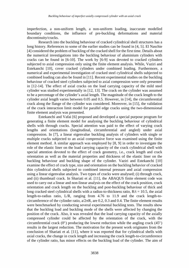
Consider a mild steel cylinder with a radius, R and a nominal wall thickness, t, having the
axial length, L, and the crack length, 2a, as sketched in Figure 1. Four cylindrical
specimens were manufactured from a flat mild steel plate. An axial crack of various
lengths was introduced in the specimen during the manufacturing process. The nominal
geometry of the models was the same, and it is given by R/t = 100, L/R = 2.2, and the
wall thickness t = 0.5 mm. Cylinders were joined together using the Metal Inert Gas
(MIG) welding process. All cylinders are to be subjected to axial compression. The
specimens were designated as cylindrical models: 2, 5, 6, and 7.
Figure 1. Geometry of the cylindrical model (a) Section through the cylindrical shell;
(b) Insert illustrating the crack region.
Experimental Procedure
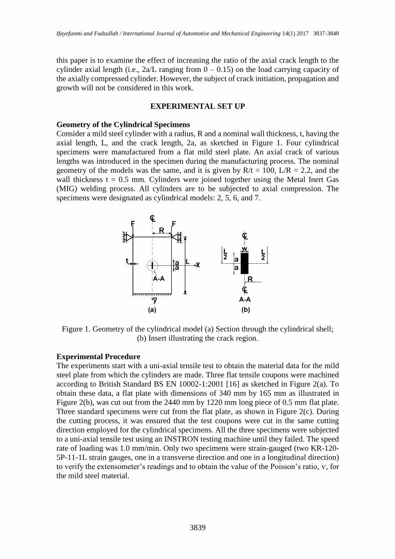
The experiments start with a uni-axial tensile test to obtain the material data for the mild
steel plate from which the cylinders are made. Three flat tensile coupons were machined
according to British Standard BS EN 10002-1:2001 [16] as sketched in Figure 2(a). To
obtain these data, a flat plate with dimensions of 340 mm by 165 mm as illustrated in
Figure 2(b), was cut out from the 2440 mm by 1220 mm long piece of 0.5 mm flat plate.
Three standard specimens were cut from the flat plate, as shown in Figure 2(c). During
the cutting process, it was ensured that the test coupons were cut in the same cutting
direction employed for the cylindrical specimens. All the three specimens were subjected
to a uni-axial tensile test using an INSTRON testing machine until they failed. The speed
rate of loading was 1.0 mm/min. Only two specimens were strain-gauged (two KR-120-
5P-11-1L strain gauges, one in a transverse direction and one in a longitudinal direction)
to verify the extensometer’s readings and to obtain the value of the Poisson’s ratio, ѵ, for
the mild steel material.
Buckling behaviour of imperfect axially compressed cylinder with an axial crack
3840
Figure 2. (a) Dimensions of the flat tensile specimen in mm; (b) The cutting
pattern of the tensile specimens; (c) Three standard tensile specimens.
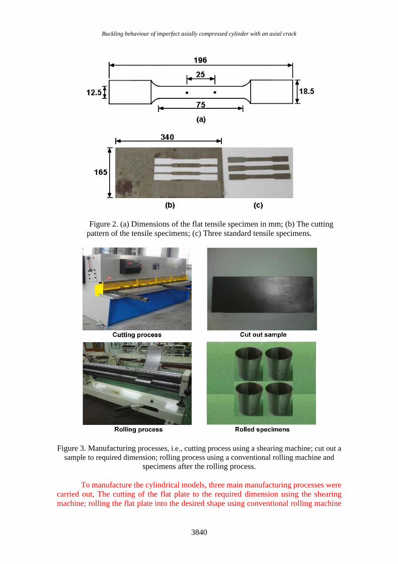
Figure 3. Manufacturing processes, i.e., cutting process using a shearing machine; cut out a
sample to required dimension; rolling process using a conventional rolling machine and
specimens after the rolling process.
To manufacture the cylindrical models, three main manufacturing processes were
carried out, The cutting of the flat plate to the required dimension using the shearing
machine; rolling the flat plate into the desired shape using conventional rolling machine
Ifayefunmi and Fadzullah / International Journal of Automotive and Mechanical Engineering 14(1) 2017 3837-3848
3841
and welding the meridional axis of the rolled specimen using inert metal gas (MIG)
welding process. Figure 3 presents the steps adopted during the manufacturing process.
The flat plate is cut into the desired dimension (i.e., length and circumference of the
cylinder) as shown in Figure 3(b) using the shearing machine (Figure 3(a)). Then, the flat
plate is rolled into the desired shape using the conventional rolling machine as depicted
in Figure 3(c). Special care was taken during the rolling process until the desired
cylindrical shape is achieved. Figure 3(d) depicts the photograph of all specimens after
the rolling process.
The rolling process only transforms the flat plate into a hollow cylindrical shape,
but the meridional axis of the hollow cylinder needs to be joined. The joining process of
the hollow cylinder was achieved using a Metal Inert Gas (MIG) welding process. During
the welding process, an axial crack of varying magnitude was introduced on all the
specimens. The magnitude of the ratio of axial crack, 2a, to the cylinder axial length,
2a/L, was 0.0, 0.05, 0.1 and 0.15. The axial crack introduced on cylindrical models 5, 6,
and 7 was 0.05, 0.1, and 0.15, respectively. However, cylindrical model 2 was assumed
to be a nearly perfect model with no cracks. Since the cylinders were symmetric, it was
decided to locate the crack in the middle of the cylinder’s axial length (see Figure 1(a)).
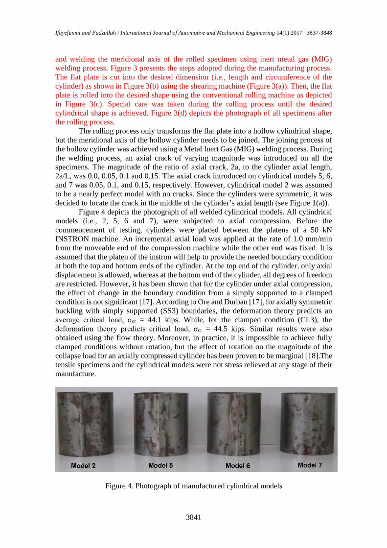
Figure 4 depicts the photograph of all welded cylindrical models. All cylindrical
models (i.e., 2, 5, 6 and 7), were subjected to axial compression. Before the
commencement of testing, cylinders were placed between the platens of a 50 kN
INSTRON machine. An incremental axial load was applied at the rate of 1.0 mm/min
from the moveable end of the compression machine while the other end was fixed. It is
assumed that the platen of the instron will help to provide the needed boundary condition
at both the top and bottom ends of the cylinder. At the top end of the cylinder, only axial
displacement is allowed, whereas at the bottom end of the cylinder, all degrees of freedom
are restricted. However, it has been shown that for the cylinder under axial compression,
the effect of change in the boundary condition from a simply supported to a clamped
condition is not significant [17]. According to Ore and Durban [17], for axially symmetric
buckling with simply supported (SS3) boundaries, the deformation theory predicts an
average critical load, σcr = 44.1 kips. While, for the clamped condition (CL3), the
deformation theory predicts critical load, σcr = 44.5 kips. Similar results were also
obtained using the flow theory. Moreover, in practice, it is impossible to achieve fully
clamped conditions without rotation, but the effect of rotation on the magnitude of the
collapse load for an axially compressed cylinder has been proven to be marginal [18].The
tensile specimens and the cylindrical models were not stress relieved at any stage of their
manufacture.
Figure 4. Photograph of manufactured cylindrical models
Buckling behaviour of imperfect axially compressed cylinder with an axial crack
3842
RESULTS AND DISCUSSION
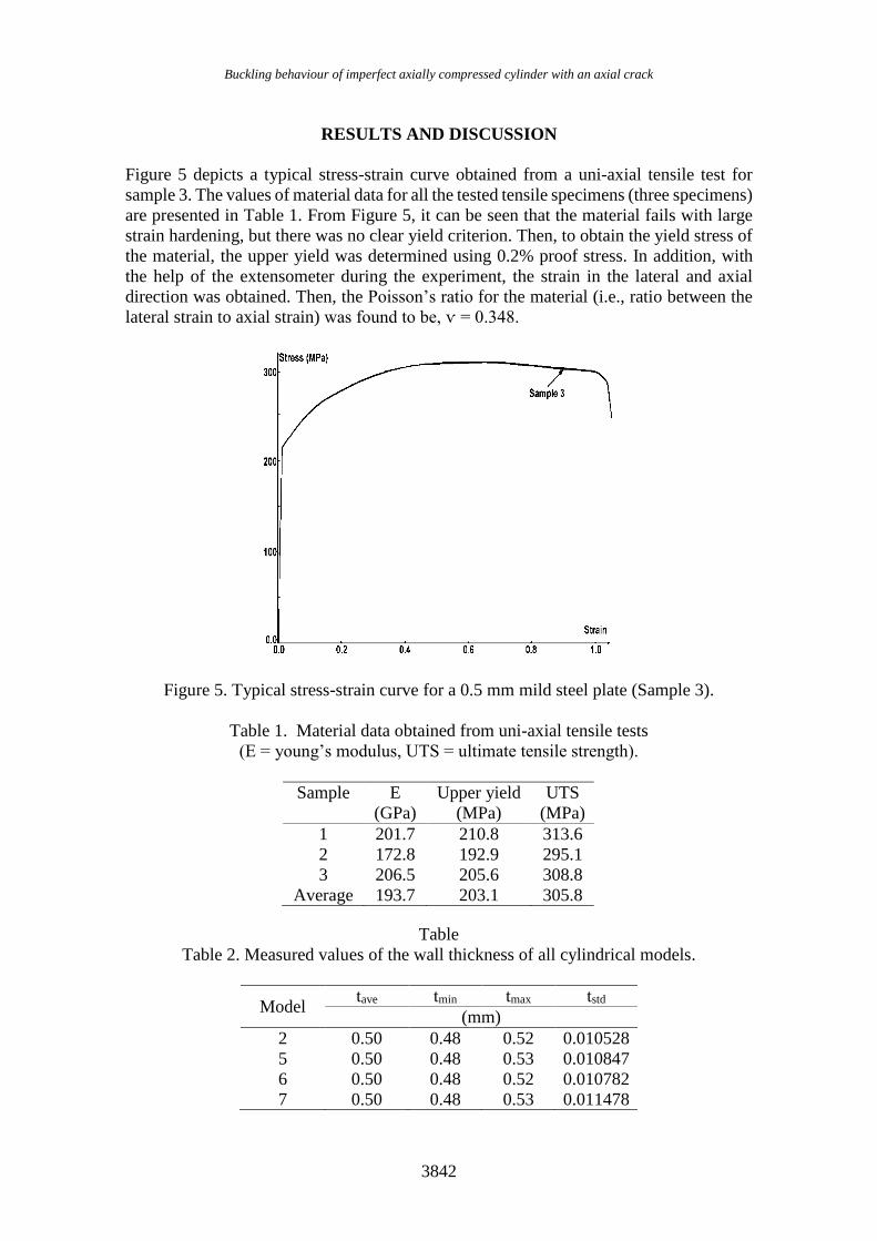
Figure 5 depicts a typical stress-strain curve obtained from a uni-axial tensile test for
sample 3. The values of material data for all the tested tensile specimens (three specimens)
are presented in Table 1. From Figure 5, it can be seen that the material fails with large
strain hardening, but there was no clear yield criterion. Then, to obtain the yield stress of
the material, the upper yield was determined using 0.2% proof stress. In addition, with
the help of the extensometer during the experiment, the strain in the lateral and axial
direction was obtained. Then, the Poisson’s ratio for the material (i.e., ratio between the
lateral strain to axial strain) was found to be, ѵ = 0.348.
Figure 5. Typical stress-strain curve for a 0.5 mm mild steel plate (Sample 3).
Table 1. Material data obtained from uni-axial tensile tests
(E = young’s modulus, UTS = ultimate tensile strength).
Table
Table 2. Measured values of the wall thickness of all cylindrical models.
Model tave tmin tmax tstd
(mm)
2 0.50 0.48 0.52 0.010528
5 0.50 0.48 0.53 0.010847
6 0.50 0.48 0.52 0.010782
7 0.50 0.48 0.53 0.011478
Sample E
(GPa)
Upper yield
(MPa)
UTS
(MPa)
1 201.7 210.8 313.6
2 172.8 192.9 295.1
3 206.5 205.6 308.8
Average 193.7 203.1 305.8
Ifayefunmi and Fadzullah / International Journal of Automotive and Mechanical Engineering 14(1) 2017 3837-3848
3843
Prior to the collapse test, a number of measurements of the wall thickness, axial
length, diameter and crack width was taken on all cylindrical models. The importance of
conducting the initial geometric measurements of the shells was highlighted in [19]. First,
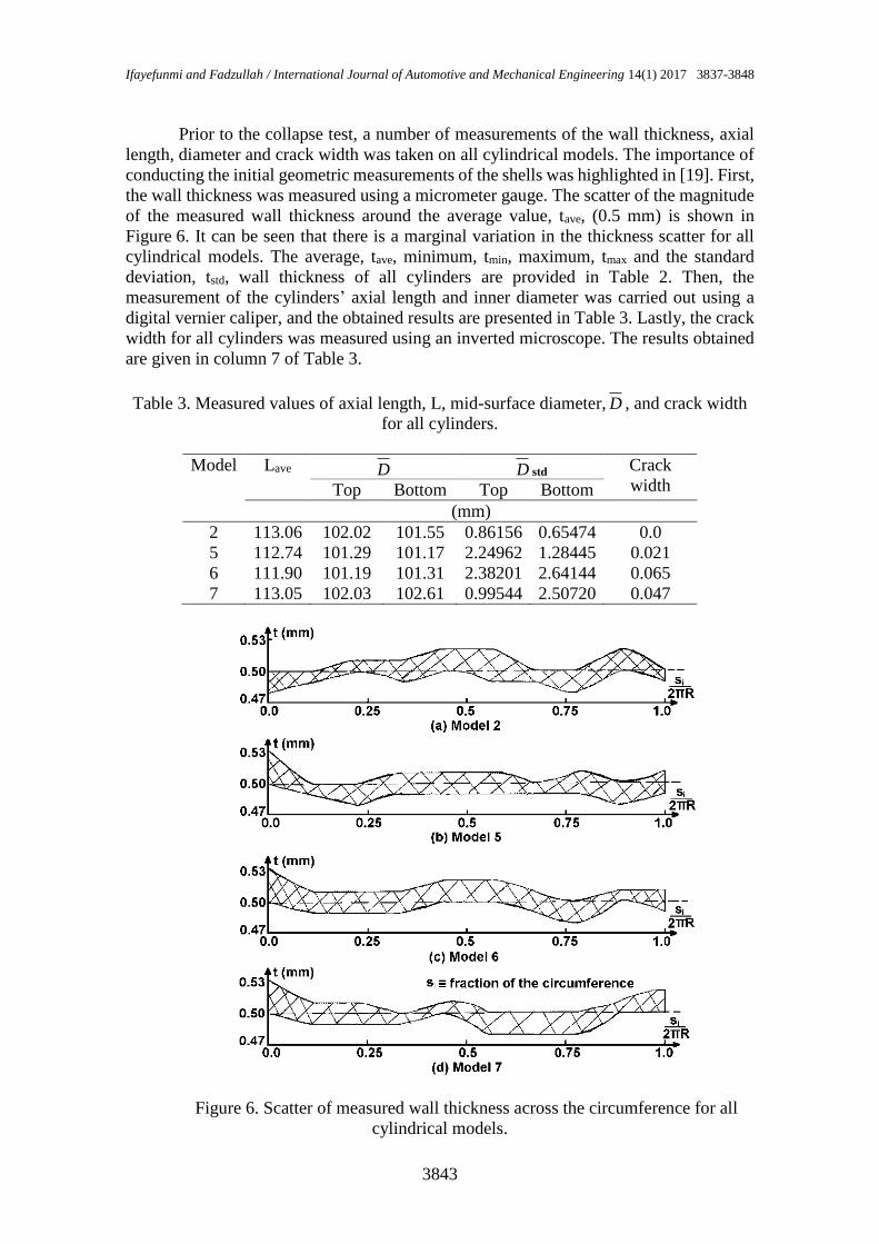
the wall thickness was measured using a micrometer gauge. The scatter of the magnitude
of the measured wall thickness around the average value, tave, (0.5 mm) is shown in
Figure 6. It can be seen that there is a marginal variation in the thickness scatter for all
cylindrical models. The average, tave, minimum, tmin, maximum, tmax and the standard
deviation, tstd, wall thickness of all cylinders are provided in Table 2. Then, the
measurement of the cylinders’ axial length and inner diameter was carried out using a
digital vernier caliper, and the obtained results are presented in Table 3. Lastly, the crack
width for all cylinders was measured using an inverted microscope. The results obtained
are given in column 7 of Table 3.
Table 3. Measured values of axial length, L, mid-surface diameter, D , and crack width
for all cylinders.
Model Lave D D std Crack
width Top Bottom Top Bottom
(mm)
2 113.06 102.02 101.55 0.86156 0.65474 0.0
5 112.74 101.29 101.17 2.24962 1.28445 0.021
6 111.90 101.19 101.31 2.38201 2.64144 0.065
7 113.05 102.03 102.61 0.99544 2.50720 0.047
Figure 6. Scatter of measured wall thickness across the circumference for all
cylindrical models.
Buckling behaviour of imperfect axially compressed cylinder with an axial crack
3844
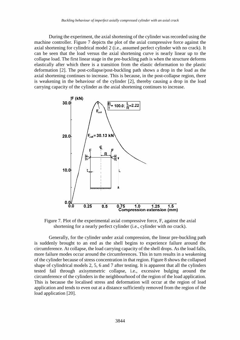
During the experiment, the axial shortening of the cylinder was recorded using the
machine controller. Figure 7 depicts the plot of the axial compressive force against the
axial shortening for cylindrical model 2 (i.e., assumed perfect cylinder with no crack). It
can be seen that the load versus the axial shortening curve is nearly linear up to the
collapse load. The first linear stage in the pre-buckling path is when the structure deforms
elastically after which there is a transition from the elastic deformation to the plastic
deformation [2]. The post-collapse/post-buckling path shows a drop in the load as the
axial shortening continues to increase. This is because, in the post-collapse region, there
is weakening in the behaviour of the cylinder [2], thereby causing a drop in the load
carrying capacity of the cylinder as the axial shortening continues to increase.
Figure 7. Plot of the experimental axial compressive force, F, against the axial
shortening for a nearly perfect cylinder (i.e., cylinder with no crack).
Generally, for the cylinder under axial compression, the linear pre-buckling path
is suddenly brought to an end as the shell begins to experience failure around the
circumference. At collapse, the load carrying capacity of the shell drops. As the load falls,
more failure modes occur around the circumferences. This in turn results in a weakening
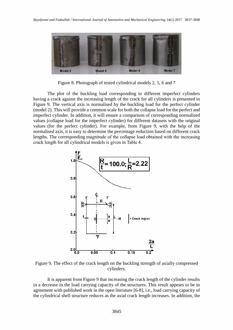
of the cylinder because of stress concentration in that region. Figure 8 shows the collapsed
shape of cylindrical models 2, 5, 6 and 7 after testing. It is apparent that all the cylinders
tested fail through axisymmetric collapse, i.e., excessive bulging around the
circumference of the cylinders in the neighbourhood of the region of the load application.
This is because the localised stress and deformation will occur at the region of load
application and tends to even out at a distance sufficiently removed from the region of the
load application [20].
Ifayefunmi and Fadzullah / International Journal of Automotive and Mechanical Engineering 14(1) 2017 3837-3848
3845
Figure 8. Photograph of tested cylindrical models 2, 5, 6 and 7
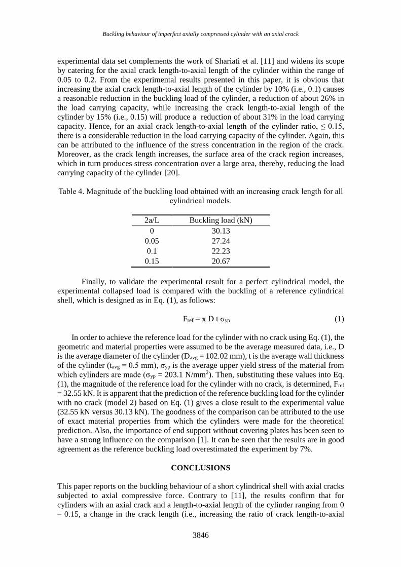
The plot of the buckling load corresponding to different imperfect cylinders
having a crack against the increasing length of the crack for all cylinders is presented in
Figure 9. The vertical axis is normalised by the buckling load for the perfect cylinder
(model 2). This will provide a common scale for both the collapse load for the perfect and
imperfect cylinder. In addition, it will ensure a comparison of corresponding normalised
values (collapse load for the imperfect cylinder) for different datasets with the original
values (for the perfect cylinder). For example, from Figure 9, with the help of the
normalised axis, it is easy to determine the percentage reduction based on different crack
lengths. The corresponding magnitude of the collapse load obtained with the increasing
crack length for all cylindrical models is given in Table 4.
Figure 9. The effect of the crack length on the buckling strength of axially compressed
cylinders.
It is apparent from Figure 9 that increasing the crack length of the cylinder results
in a decrease in the load carrying capacity of the structures. This result appears to be in
agreement with published work in the open literature [6-8], i.e., load carrying capacity of
the cylindrical shell structure reduces as the axial crack length increases. In addition, the
Buckling behaviour of imperfect axially compressed cylinder with an axial crack
3846
experimental data set complements the work of Shariati et al. [11] and widens its scope
by catering for the axial crack length-to-axial length of the cylinder within the range of
0.05 to 0.2. From the experimental results presented in this paper, it is obvious that
increasing the axial crack length-to-axial length of the cylinder by 10% (i.e., 0.1) causes
a reasonable reduction in the buckling load of the cylinder, a reduction of about 26% in
the load carrying capacity, while increasing the crack length-to-axial length of the
cylinder by 15% (i.e., 0.15) will produce a reduction of about 31% in the load carrying
capacity. Hence, for an axial crack length-to-axial length of the cylinder ratio, ≤ 0.15,
there is a considerable reduction in the load carrying capacity of the cylinder. Again, this
can be attributed to the influence of the stress concentration in the region of the crack.
Moreover, as the crack length increases, the surface area of the crack region increases,
which in turn produces stress concentration over a large area, thereby, reducing the load
carrying capacity of the cylinder [20].
Table 4. Magnitude of the buckling load obtained with an increasing crack length for all
cylindrical models.
2a/L Buckling load (kN)
0 30.13
0.05 27.24
0.1 22.23
0.15 20.67
Finally, to validate the experimental result for a perfect cylindrical model, the
experimental collapsed load is compared with the buckling of a reference cylindrical
shell, which is designed as in Eq. (1), as follows:
Fref = π D t σyp (1)
In order to achieve the reference load for the cylinder with no crack using Eq. (1), the
geometric and material properties were assumed to be the average measured data, i.e., D
is the average diameter of the cylinder (Davg = 102.02 mm), t is the average wall thickness
of the cylinder (tavg = 0.5 mm), σyp is the average upper yield stress of the material from
which cylinders are made (σyp = 203.1 N/mm2). Then, substituting these values into Eq.
(1), the magnitude of the reference load for the cylinder with no crack, is determined, Fref
= 32.55 kN. It is apparent that the prediction of the reference buckling load for the cylinder
with no crack (model 2) based on Eq. (1) gives a close result to the experimental value
(32.55 kN versus 30.13 kN). The goodness of the comparison can be attributed to the use
of exact material properties from which the cylinders were made for the theoretical
prediction. Also, the importance of end support without covering plates has been seen to
have a strong influence on the comparison [1]. It can be seen that the results are in good
agreement as the reference buckling load overestimated the experiment by 7%.
CONCLUSIONS
This paper reports on the buckling behaviour of a short cylindrical shell with axial cracks
subjected to axial compressive force. Contrary to [11], the results confirm that for
cylinders with an axial crack and a length-to-axial length of the cylinder ranging from 0
– 0.15, a change in the crack length (i.e., increasing the ratio of crack length-to-axial
Ifayefunmi and Fadzullah / International Journal of Automotive and Mechanical Engineering 14(1) 2017 3837-3848
3847
length of the cylinder, 2a/L) will cause a considerable reduction in the load carrying
capacity of the cylinders. The crack length extending by about 5% of the cylinder axial
length will cause a reduction of approximately 10% in the load carrying capacity of the
cylinder. Increasing the crack length to 10% will result in a reduction of about 26% in the
buckling strength of the cylinder. While, if the crack length extends by about 15% of the
cylinder axial length, this will produce a reduction of about 31% in the buckling strength
of the cylinder. However, this might not be true for the crack length-to-cylinder axial
length > 0.2, [12]. Finally, the extension of the experimental study using a numerical
analysis and a theoretical calculation to validate the effect of the crack length on the
buckling strength of the cylinder would provide valuable data and add to the strengthening
of modelling and the analysis methodology of the cracked shells.
ACKNOWLEDGEMENTS
The author will like to acknowledge the financial support received from the Faculty of
Engineering Technology, Universiti Teknikal Malaysia Melaka (UTeM) and Ministry of
Education Malaysia under Research Acculturation Grant Scheme
RAGS/1/2014/TK04/FKM/B00069 for the financial support.
REFERENCES
[1] Ifayefunmi O. Buckling behavior of axially compressed cylindrical shells:
Comparison of theoretical and experimental data. Thin-Walled Structures.
2016;98:558-64.
[2] Song C, Teng J, Rotter J. Imperfection sensitivity of thin elastic cylindrical shells
subject to partial axial compression. International Journal of Solids and Structures.
2004;41:7155-80.
[3] Khalili P, Tarlochan F, Hamouda AMS, Al-Khalifa K. Energy absorption
capability of thin-walled aluminium tubes under crash loading. Journal of
Mechanical Engineering and Sciences. 2015;9:1734-43.
[4] El Naschie M. A branching solution for the local buckling of a circumferentially
cracked cylindrical shell. International Journal of Mechanical Sciences.
1974;16:689-97.
[5] Dyshel MS. Stability of a cracked cylindrical shell in tension. Soviet Applied
Mechanics. 1989;25:542-8.
[6] Estekanchi H, Vafai A. On the buckling of cylindrical shells with through cracks
under axial load. Thin-walled Structures. 1999;35:255-74.
[7] Jahromi BH, Vaziri A. Instability of cylindrical shells with single and multiple
cracks under axial compression. Thin-Walled Structures. 2012;54:35-43.
[8] Kim Y. Buckling of a cracked cylindrical shell reinforced with an elastic liner:
Northeastern University; 2011.
[9] Kim Y, Haghpanah B, Ghosh R, Ali H, Hamouda A, Vaziri A. Instability of a
cracked cylindrical shell reinforced by an elastic liner. Thin-walled Structures.
2013;70:39-48.
[10] Vaziri A, Estekanchi H. Buckling of cracked cylindrical thin shells under
combined internal pressure and axial compression. Thin-Walled Structures.
2006;44:141-51.
Buckling behaviour of imperfect axially compressed cylinder with an axial crack
3848
[11] Shariati M, Sedighi M, Saemi J, Eipakchi H, Allahbakhsh H. Numerical and
experimental investigation on ultimate strength of cracked cylindrical shells
subjected to combined loading. Mechanika. 2010;4.
[12] Ifayefunmi O. The effect of axial crack on the buckling behavior of axially
compressed cylinders. International Journal of Mechanical and Mechatronics
Engineering. 2016;16:12-7.
[13] Ifayefunmi O, Kasiman N, Khan HI. Experimental investigation of buckling
behavior of cracked cylindrical shells subjected to axial compression. Proceedings
of Mechanical Engineering Research Day. 2016;2016:153-4.
[14] Ifayefunmi O, Hap LK. Effect of material discontinuity on the flanges of axially
compressed cylinder. Journal of Mechanical Engineering and Sciences.
2016;10:2084-97.
[15] Daud R, Ariffin A, Abdullah S. Validation of crack interaction limit model for
parallel edge cracks using two-dimensional finite element analysis. International
Journal of Automotive and Mechanical Engineering. 2013;7: 993-1003
[16] EN B. 10002-1: 2001. Tensile testing of metallic materials method of test at
ambient temperature. 2001.
[17] Ore E, Durban D. Elastoplastic buckling of axially compressed circular cylindrical
shells. International Journal of Mechanical Sciences. 1992;34:727-42.
[18] Ifayefunmi O, Błachut J. The effect of shape, thickness and boundary
imperfections on plastic buckling of cones. Proceedings of the ASME 2011 30th
International Conference on Ocean, Offshore and Arctic Engineering,
OMAE2011, Rotterdam, The Netherlands, June2011. p. 19-24.
[19] Singer J. Buckling Experiments on Shells: A Review of recent developments:
technion-IIT, Department of Aeronautical Engineering; 1980.
[20] Ali MB, Abdullah S, Nuawi MZ, Ariffin A, Nopiah Z. Evaluating instrumented
Charpy impact strain signals using curve fitting equations. Journal of Central
South University. 2014;21:600-9.


![THERMAL BUCKLING OF FUNCTIONALLY GRADED RECTANGULAR PLATES · 3 investigated thermal buckling behaviour of the FGM plates. Ferreira et al. [12, 13] performed static and dynamic analysis](https://img.pdfslide.us/doc/110x75/5b894e327f8b9a851a8d4dc4/thermal-buckling-of-functionally-graded-rectangular-plates-3-investigated-thermal.jpg)


![Study on Buckling Behaviour of Hyperbolic Cooling … on Buckling Behaviour of Hyperbolic Cooling Towers Ashok P Ponath [1], Manju George [2] Department of Civil Engineering Mahatma](https://img.pdfslide.us/doc/110x75/5ab81ae47f8b9ad13d8c2d2a/study-on-buckling-behaviour-of-hyperbolic-cooling-on-buckling-behaviour-of-hyperbolic.jpg)