Embed Size (px)
Citation preview
Journal of Engineering Volume 18 August 2012 Number 8
961
Buckling Analysis Of Damaged Composite Plates Under Uniform Or Non-Uniform Compressive Load
Abstract.
The present study focused mainly on the buckling behavior of composite laminated plates subjected to mechanical loads. Mechanical loads are analyzed by experimental analysis, analytical analysis (for laminates without cutouts) and numerical analysis by finite element method (for laminates with and without cutouts) for different type of loads which could be uniform or non-uniform, uniaxial or biaxial. In addition to many design parameters of the laminates such as aspect ratio, thickness ratio, and lamination angle or the parameters of the cutout such as shape, size, position, direction, and radii rounding) which are changed to study their effects on the buckling characteristics with various boundary conditions. Levy method of classical laminated plate theory and Finite element coded by ANSYS 13.0 is used to formulate the theoretical model. Results are compared with other researches and good agreement was obtained.
Key words:
Composite, Buckling analysis, Finite element method, ANSYS program, uniform load, non-uniform load
الخالصة:
االحمال الميكانيكية . رضة الحمال ميكانيكيةعهذا البحث يرآز بصورة رئيسية على تصرف االنبعاج للصفائح المرآبة الم و طرق عددية بأستخدام طريقة العناصر المحددة) غير الحاوية على ثقوبللصفائح( تحليلية،تحليلها بطرق عملية تم
ألنواع مختلفة من األحمال التي من الممكن ان تكون منتظمة او غير )للصفئح التي تحتوي والتي ال تحتوي على ثقوب(سمكها و ، لصفيحة آالنسبة بين اطوالهاد آبير من عناصر التصميم لالى عد باألضافة باتجاه واحد او باتجاهين، منتطمة
يرها لدراسة يوالتي تم تغاالتجاه و نصف قطر الحافات ، الموقع، الحجم، زاوية ميالن الفايبر او متغيرات الثقوب آالشكلاستخدمت لتمثل ناصر المحددة نظرية الصفائح المرآبة التقليدية والع. تأثيرها على حمل االنبعاج مع اشكال اسناد مختلفة
. النموذج التحليلي وتمت مقارنة النتائج مع بحوث سابقة والحصول على توافق جيد بينها
Kawther Khalid Younus Mechanics Engineening Department
university of Baghdadmail: [email protected]
Prof. Dr. Adnan Naji Jameel Mechanics Engineening
Department university of Baghdad e-mail:[email protected]
Buckling Analysis Of Damaged Composite Plates Under Uniform Or Non-Uniform Compressive Load
Prof. Dr. Adnan Naji Jameel Kawther Khalid Younus
ج
962
Introduction
Laminated composites are gaining wider use because of their case of handling, good mechanical properties and low fabrication cost. They also possess excellent damage tolerance and impact resistance, excellent stiffness and weight characteristics. Cutouts are commonly found as access ports for mechanical and electrical systems or simply to reduce weight. The ability to monitor such
structures and detect damage before it reaches critical levels is of outmost importance in the composite material used in different fields, such plates which contain damages are vulnerable to buckle when subjected to various types of in-plane loadings; therefore it is of great importance to fully understand the effects of various parameters on its buckling load. Many researchers investigated this problem over the years from different perspectives; the following paragraphs summarize their works.
[Austin C. D. 2003] investigated the buckling of fiberglass reinforced plastic FRP laminated plates using the commercially available ANSYS finite element software. [1] [Ko.William L. 1998] studied the compressive buckling analysis on metal-matrix composite (MMC) plates (square, rectangle) with central square holes [2]. [Ko. William L. 1998] in this study mechanical- and thermal-buckling analyses were performed on rectangular plates (titanium alloy) with central cutouts [3]. [Kitsuda K. 1935] investigated experimentally the ultimate strength of rectangular steel plates under shearing stresses when the plate contains lightening holes, [4]. [Kumar A. R. 2009] examined experimentally the influence of cutout shape (circular, square and rectangular) on the buckling load of composite plate.[5]. [Lee Y. J. et.al 1989] studied the buckling behavior of orthotropic square plate, either with or without a central circular hole. Results showed that the existence of central circular holes may cause a higher buckling
strength than the plates without holes [6]. [Pradyumna
S. and Bandyopadhyay J. N.
2005] studied the buckling analysis of square composite plates with central circular cutout using a higher-order shear deformable plate element based on a higher-order theory. A simply supported edges conditions are considered. Results show that the buckling load decreases with the increase in cutouts size [7]. [Teh Hu H. and Lin B. 1995] studied the buckling resistance of symmetrically graphite/epoxy laminated plates (square, rectangle) and subjected to uniaxial compression [8]. [Tekin M. D. and Altan M. F.1996] investigated an approach buckling analysis to compare buckling load of the reinforced plate with circular hole and without hole [9]. [Therib J.H. 2004] this work includes performing mechanical buckling analysis on square and rectangular aluminum plates with central (square or circular) cutout compressed by a uniaxial load. [10].
From above literature review, it can be observed that all literatures are approximately limited to one type of load such as uniaxial uniform compressive buckling load, and one shape of cutout such as circle or square. i.e, there are no comparison between other shapes of cutouts or type of loads such as taking into consideration the non-uniform loads, enough types of boundary conditions or enough parameters which effect on the buckling behavior, In the present work, mechanical buckling analysis of laminated plates with elastic properties has investigated analytically, experimentally, and numerically. Under the present study, the formulations are based the classical laminated plate theory, buckling characteristics of SSSS, SCSC, SFSF, SFSC, SSSC, SSSF for cross-ply and angle-ply made up of fiber-glass composites are studied theoretically under uniaxial and biaxial compressive buckling load, In addition to the numerical analysis of the non-uniform compressive buckling load.
Theoretical analysis
The theoretical formulation is based upon the classical laminated plate theory (CLPT),
Journal of Engineering Volume 18 August 2012 Number 8
963
then equation of motion are derived and solved using Fourier series to obtain buckling by solving eigenvalue problem for different boundary conditions. Analytical solution for cross-ply and angle-ply laminated plate subjected to mechanical loads are obtained by using CLPT for Levy
solution.
Classical laminated plate theory
:Displacement
The classical laminated plate theory (CLPT) based on assuming the straight line perpendicular to the mid surface before deformation remains straight after deformation.
The displacement field of CLPT contains only three dependent variables [11]:
u(x,y)=(x,y)+z (x,y) (1. a)
v(x,y)=(x,y)+z (x,y) (1. b)
w(x,y)=(x,y) (1. c)
Where: , denote rotations about y and x-axes respectively, and , ,
denote the displacement components along (x, y, z) directions respectively of a point on the mid-plane (i.e…z=0).
:Stress and Strain
The total strains can be written as follows
= +z
=+z (2)
The transformed stress-strain relations of an orthotropic lamina in a plane state of
stress are; for , see [11] :
= (3)
The resultant of inplane force Nxx ,Nyy and Nxy and moments Mxx, Myy and Mxy acting on a laminate are obtained by integration of the stress in each layer or lamina through the laminate thickness. Knowing the stress in terms of the displacement, we can obtain the inplane force resultants Nxx, Nyy, Nxy, Mxx, Myy
and Mxy.
The inplane force resultants are defined as
=dz = dz
(4.a)
Where: , and are normal and shear stress.
=+
(4.b)
= z dz = z dz (5.a)
= +
(5.b)
Here, are the extensional stiffness, the coupling stiffness, and the bending
stiffness.
Buckling Analysis Of Damaged Composite Plates Under Uniform Or Non-Uniform Compressive Load
Prof. Dr. Adnan Naji Jameel Kawther Khalid Younus
ج
964
= ( - (6.a)
= ( - (6.b)
= ( - (6.c)
:Equation of motion
The Euler-lagrange equations are obtained by setting the coefficient of , ,
to zero separately [11] :
=0 (7.a)
: = 0 (7. b)
: + + +
+ =0 (7.c)
: Where - =
= -
, are compressive loads
These equations of motion (7 a-c) can be expressed in terms of displacements
), , by substituting the forces results from eqs. (4 , 5) into eq. (7.a) to (7.c) and get partial differential equations, then the analytical solution done by levy method as derived in [11].
Numerical analysis
:Element selection and modeling
An element called shell281 as shown in fig.(1) is selected which is suitable for analyzing thin to moderately thick shell structures. The element has eight nodes with six degrees of freedom at each node: translations in the x, y, and z axes, and rotations about the x, y, and z axes. It may be used for layered applications for modeling composite shells. It is include the
effects of transverse shear deformation. The accuracy in modeling composite shells is governed by the first order shear deformation theory. The shell section allows for layered shell definition, options are available for specifying the thickness, material, orientation through the thickness
of the layers [12].
Finite element method has been employed to analyze critical buckling load. The model was developed in ANSYS 13.0 using the 121 (11*11) quadrate elements. The global x coordinate is directed along the width of the plate, while the global y coordinate is directed along the length and the global z direction corresponds to the thickness direction and taken to be the outward normal of the plate surface. There are 11 elements in the axial direction and 11 along the width (i.e. 8424 DOF). Convergence study is the reasons for choosing the particular mesh used in this study. A linear buckling analysis (eigenvalue buckling) was performed on the model to calculate the minimum buckling load of the structure as in the following
equation:
([K] + [S])= {0}
Where: [K] = stiffness matrix [S] = stress matrix
= ith eigenvalue (used to multiply the loads which generated [S])
= ith eigenvector of displacements
Verification case studies
In the present study, Series of preselected cases are modeled to verify the accuracy of the method of analysis. The results are compared to analytical solution (Levy) and numerical solution (Finite element method).
*Comparison between analytical solution (levy method) and the FEM solution (ANSYS program) for the present work
Table (1): Dimensionless uniaxial buckling load)of SFSF anti-symmetric cross ply
Journal of Engineering Volume 18 August 2012 Number 8
965
laminates without cutout, h=1 (M.P. from table (4)
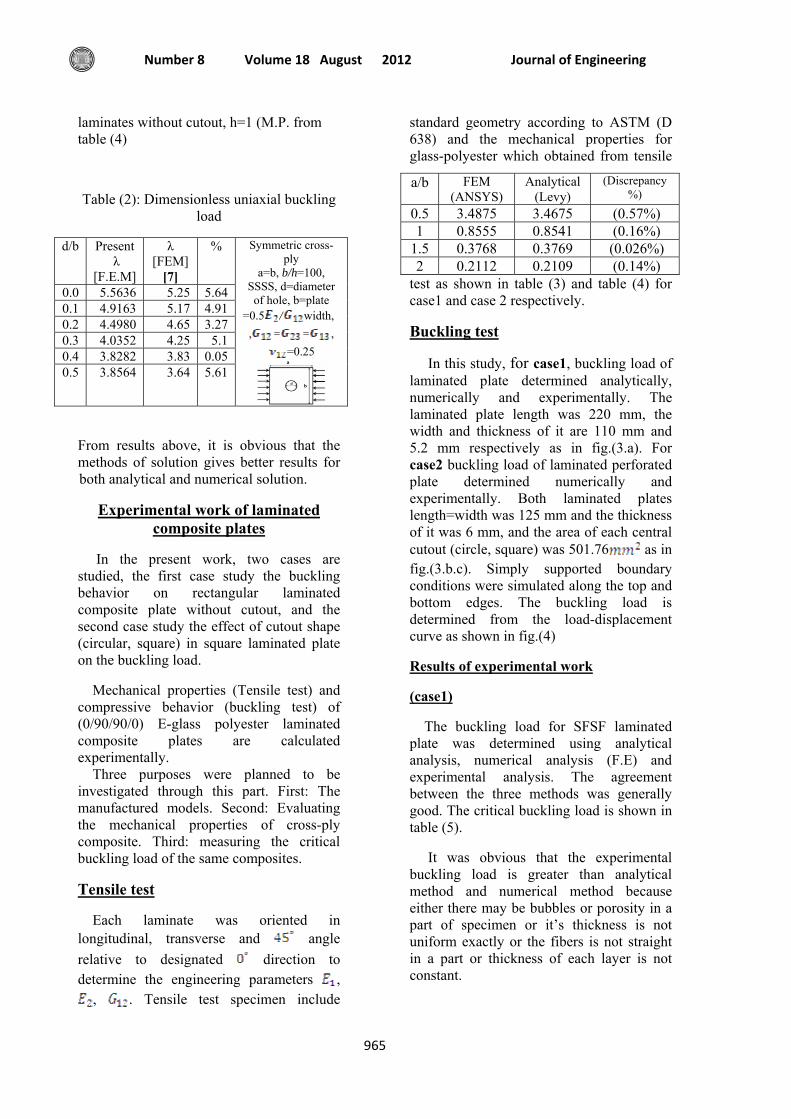
Table (2): Dimensionless uniaxial buckling load
% λ [FEM]
[7]
Present λ
[F.E.M]
d/b
5.64 5.25 5.5636 0.0 4.91 5.17 4.9163 0.1 3.27 4.65 4.4980 0.2
5.1 4.25 4.0352 0.3 0.05 3.83 3.8282 0.4
Symmetric cross-ply
a=b, b/h=100, SSSS, d=diameter of hole, b=plate
width, /=0.5 ,==,
=0.25
5.61 3.64 3.8564 0.5
From results above, it is obvious that the methods of solution gives better results for both analytical and numerical solution.
Experimental work of laminated composite plates
In the present work, two cases are studied, the first case study the buckling behavior on rectangular laminated composite plate without cutout, and the second case study the effect of cutout shape (circular, square) in square laminated plate on the buckling load.
Mechanical properties (Tensile test) and compressive behavior (buckling test) of (0/90/90/0) E-glass polyester laminated composite plates are calculated experimentally. Three purposes were planned to be investigated through this part. First: The manufactured models. Second: Evaluating the mechanical properties of cross-ply composite. Third: measuring the critical buckling load of the same composites.
Tensile test
Each laminate was oriented in longitudinal, transverse and angle relative to designated direction to determine the engineering parameters ,
, . Tensile test specimen include
standard geometry according to ASTM (D 638) and the mechanical properties for glass-polyester which obtained from tensile
test as shown in table (3) and table (4) for case1 and case 2 respectively.
Buckling test
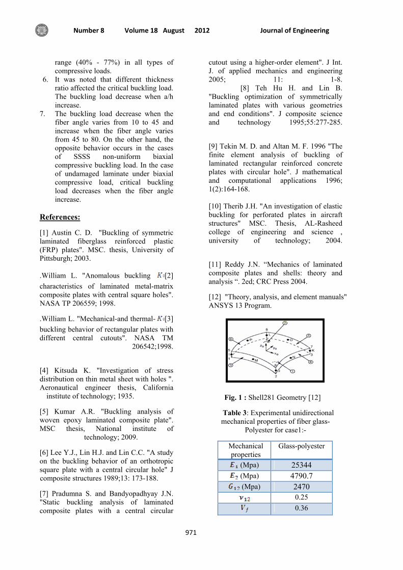
In this study, for case1, buckling load of laminated plate determined analytically, numerically and experimentally. The laminated plate length was 220 mm, the width and thickness of it are 110 mm and 5.2 mm respectively as in fig.(3.a). For case2 buckling load of laminated perforated plate determined numerically and experimentally. Both laminated plates length=width was 125 mm and the thickness of it was 6 mm, and the area of each central cutout (circle, square) was 501.76 as in fig.(3.b.c). Simply supported boundary conditions were simulated along the top and bottom edges. The buckling load is determined from the load-displacement curve as shown in fig.(4)
Results of experimental work
(case1)
The buckling load for SFSF laminated plate was determined using analytical analysis, numerical analysis (F.E) and experimental analysis. The agreement between the three methods was generally good. The critical buckling load is shown in table (5).
It was obvious that the experimental buckling load is greater than analytical method and numerical method because either there may be bubbles or porosity in a part of specimen or it’s thickness is not uniform exactly or the fibers is not straight in a part or thickness of each layer is not constant.
(Discrepancy %)
Analytical (Levy)
FEM (ANSYS)
a/b
(0.57%) 3.4675 3.4875 0.5 (0.16%) 0.8541 0.8555 1 (0.026%) 0.3769 0.3768 1.5 (0.14%) 0.2109 0.2112 2
Buckling Analysis Of Damaged Composite Plates Under Uniform Or Non-Uniform Compressive Load
Prof. Dr. Adnan Naji Jameel Kawther Khalid Younus
ج
966
The analytical solution (Levy method) is nearest to experimental solution from numerical method (F.E) where the discrepancy between them is lower than numerical solution. It reaches to 7.49%.
(case2)
The buckling load for SFSF laminated square plate was determined using numerical analysis (F.E) and experimental analysis. The agreement between the two methods was generally good. The critical buckling load is shown in table (6).
It was obvious that the buckling load in the laminate with circular cutout is greater
than that with square cutout as expected and this result is similar to [5].
& nalytical Results and discussion of anumerical solutions
First part: analytical solution for laminates under uniaxial or biaxial compressive
buckling load
1. Uniaxial compressive buckling load as shown in fig (5):-
The non-dimensional buckling load =
1.1- Effect of aspect ratio:
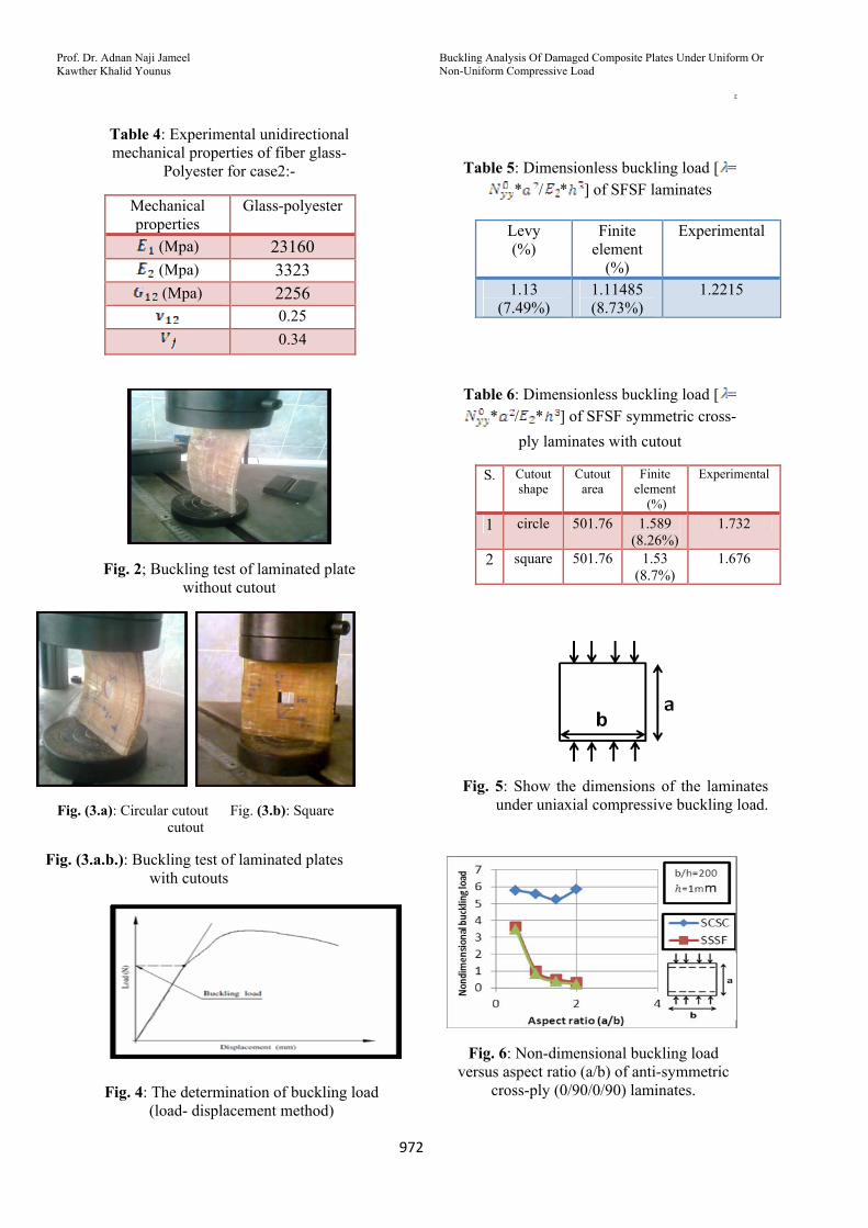
Fig (6) show that in SSSF and SFSF the buckling load decrease when a/b increase with high percentage reaches to 72.2% and 75.4% in SSSF and SFSF respectively. On the other hand in SCSC the buckling load decrease with small percentage reaches to 3.6% when a/b varies from 0.5 to 1.5, Then, it′s increases when a/b varies from 1.5 to 2. The maximum buckling load in SCSC is at a/b=2. While the minimum is at a/b=1.5. It′s worth mentioning the buckling load in SCSC is higher than other cases because of B.C′S. effect.
1.2- Effect of boundary conditions for symmetric and anti-symmetric cross-ply.
From the results listed in table (7), it can be observed that the boundary conditions always effect on the buckling load, while changing the lamination from anti-symmetric to symmetric may increase the buckling load with small percentage reaches to 1.7% as in SSSC and SCSC, or decrease it as in SFSF and SFSC, or doesn't affect the buckling load as in SFSS and SSSS.
1.3-Effect of lamination angle:
It is shown from fig (7), the buckling load decrease and increase with different
percentage when varies from 10 to 80 . In both cases the buckling load decrease when varies from 10 to 45, then it's increase
when varies from 45 to 80. The maximum buckling load for both cases is at =10.
2. Biaxial compressive buckling load as shown in fig (8):-
The non-dimensional buckling load =
2.1-Effect of aspect ratio:
Fig (9) show the buckling load decrease with high percentage in SCSC and SSSC when a/b varies from 0.5 to 1 and increase when a/b varies from 1 to 2, this percentage reaches to 52.7% and 34.3% in SCSC and SSSC respectively. On the other hand in SSSS the buckling load decreases with high percentage when a/b increase reaches to 64%. It′s worth mentioning the buckling load in SCSC is higher than other cases, because of boundary conditions effects.
2.2- Effect of lamination angle:
It is shown from fig (10), the buckling load increase and decrease with different
percentage when varies from 10 to 80 . In all cases the buckling load increase when
varies from 10 to 45, then it's decrease when varies from 45 to 80. The maximum
buckling load for all cases is at =45.
Journal of Engineering Volume 18 August 2012 Number 8
967
2.3- Effect of boundary conditions for symmetric and anti-symmetric cross-ply
From the results listed in table (8), it can be observed that the boundary conditions always effect on the buckling load, while changing the lamination from anti-symmetric to symmetric may decrease the buckling load
Second part: numerical solution using ANSYS program for laminates damaged by
cutouts
3. Uniaxial uniform compressive buckling load with square cutout as shown in fig (11.a) and with the boundary conditions as shown in fig (11.b,c):-
The non-dimensional buckling load =
3.1- Effect of cutout shape:
From the results listed in table (9), it can be observed that inserting cutout to the plate always decrease the buckling load with high percentage, but changing the cutout shape could increase or decrease the buckling load with small percentage. The buckling load in SCSC is higher than other case because of B.C′S. effect. It′s worth mentioning the sequence of cutout shape from highest value of buckling load to smallest value isn′t a standard form, but it′s different for each type of boundary conditions or other effects.
For example in the case of square-hole, the load-carrying narrow side strips along the plate boundaries are practically under uniform compressive stress fields. For the circular-hole cases, the narrow compressed side strips are under stress concentration, which reduces the buckling strengths. This fact may explain why, for most of the cases studied the buckling strengths of the plates with square holes increase more at larger hole sizes than the plates with circular holes having the same area [3], this unusual buckling characteristics of circular and square cutouts similar to the results in [3].
3.2-Effect of cutout size:
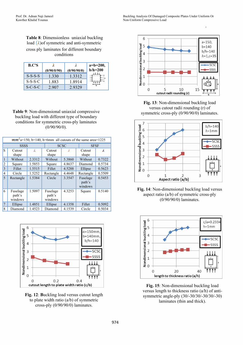
Fig (12) shows the buckling load in SCSC decrease when c/b varies from o.1 to 0.2 then it's increase when c/b varies from 0.2 to 0.5 with percentage range (0.85% - 11.6%) and the maximum buckling load is at c/b=0. On the other hand, in SSSS the buckling loads decreases when c/b increase with percentage range (1.5% - 19%), this trend similar to [6]. It′s worth mentioning the buckling load in SCSC is higher than SSSS, because of B.C′S. effect.
3.3- Effect of radii rounding (radius of fillet):
Fig.(13) show in SCSC the buckling load decrease with percentage range (0.85% -5.9%) when (r) increase from 0 to 12.5. On the other hand, in SSSS the buckling load decrease and increase with percentage range (0.7% -2.7%) when (r) increase. The maximum buckling load in SSSS is at r=0. While the minimum buckling load is at r=10, this trend similar to [10].
3.4- Effect of aspect ratio:
Fig (14) shows the buckling load decrease with high percentage in SSSS when a/b varies from 0.5 to 1 reaches to 27.1%. Then, it′s increases when a/b varies from 1to 2 with small percentage when a/b varies from 1 to 1.5 reaches to 12.1% then this percentage gets higher when a/b varies from 1to 2. The maximum buckling load in SSSS is at a/b=2. While the minimum buckling load is at a/b=1. On the other hand, in SCSC the buckling load increase from high percentage 34.77% to small percentage 9.3912%, this case similar to [10]. It′s worth mentioning the buckling load in SCSC is higher than SSSS, because of B.C′S. effect.
3.5- Effect of length to thickness ratio (a/h):
In fig(15), it can be observed that the buckling load decrease with percentage reaches to 22.8% in SCSC and 8.8 in SSSS when a/h increase, but it was shown the opposite meaning because of the effect of
Buckling Analysis Of Damaged Composite Plates Under Uniform Or Non-Uniform Compressive Load
Prof. Dr. Adnan Naji Jameel Kawther Khalid Younus
ج
968
non-dimensional value on buckling load.
3.6- Effect of cutout position:
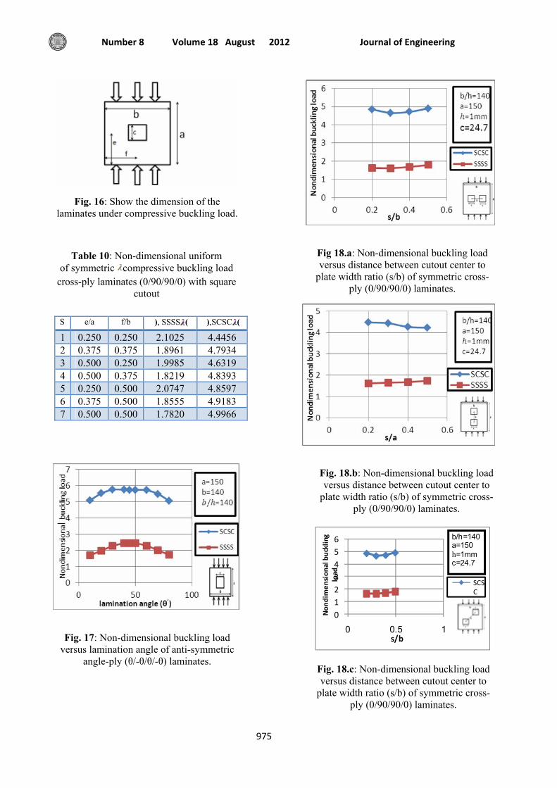
From the results listed in table (10), it can be observed that as the cutout move toward the center with the dimensions shown in fig(16) the buckling load increase in SCSC and decrease in SSSS. The buckling load in SCSC is higher than other case because of B.C′S. effect. The maximum buckling load in SSSS and the minimum buckling load in SCSC at e/a=f/b=0.250.
3.7-Effect of lamination angle:
It is shown from fig (17), the buckling load increase and decrease with different
percentage when varies from 10 to 80 . The buckling load in SCSC is higher than other case, but the percentage in SSSS is hugher than SCSCS where it′s reaches to 13.365%. The buckling load in SSSS
increase when change from 10 to 45 with percentage reaches to 26.31% and then
decrease when change from 45 to 80 with percentage reaches to 25.315%, the
maximum buckling load in SSSS is at =45, while the minimum buckling load is at =10. On the other hand, the buckling load increase and decrease with different percentage in SCSC reaches 10.8254% from
max.buckling load at =30 to min. at =80.
3.8-Effect of distance between cutouts center:
3.8. A- Distance between cutouts center parallel to the x-axis
Fig (18.a) shows that in both SCSC and SSSS the buckling load decrease when s/b varies from 0.2 to 0.3 then it′s increases when s/b varies from 0.3 to 0.5, the buckling load decrease and increase with percentage reaches to 4%. The maximum buckling load in both SCSC and SSSS is at s/b=0.5. While the minimum buckling load is at s/b=0.3.
3.8. b- Distance between cutouts center parallel to the y-axis
Fig (18.b) shows that in SCSC the buckling load decrease with percentage reaches to 3.8% when (s/a) increase, On the other hand in SSSS the buckling load increase when (s/a) increase.
3.8. c- Distance between cutouts center parallel to the diagonal
Fig (18.c) shows that in SCSC the buckling load decrease when s/b varies from 0.2 to 0.3 and increase when s/b varies from 0.3 to 0.5 with percentage reaches to 3%, On the other hand in SSSS the buckling load increase when s/b increases. The maximum buckling load in SCSC is at s/b=0.4, while the minimum buckling load is at s/b=0.3. It′s worth mentioning the buckling load in SCSC is higher than SSSS,
because of B.C′S. effect.
4. Uniaxial non-uniform compressive buckling load with fillet cutout as shown in fig (19.a) and with the boundary conditions as shown in fig (19.b,c):-
The non-dimensional buckling load =
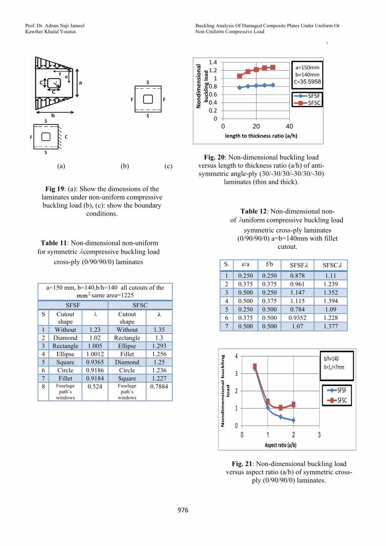
4.1-Effect of cutout shape:
From the results listed in table (11), it can be observed that inserting cutout to the plate decrease the buckling load, and that the buckling load could be increase or decrease with changing the cutout shape in a sequence depends on the boundary conditions type. It′s worth mentioning in the case of SFSF that the buckling load varies with small percentage range (0.022% - 17.1%) it′s decrease with high percentage reaches to 43% when the plate having cutout in the shape of fuselage path′s window, On the other hand, in the case of SFSC the buckling load decrease with small percentage range (0.7% - 5.4%) but its decrease with high percentage reaches to 35.8% when the cutout change from square
Journal of Engineering Volume 18 August 2012 Number 8
969
to fuselage path′s window.
4.2-Effect of length to thickness ratio (a/h):
In fig.(20), it can be observed that the buckling load decrease with percentage range (0.73% - 4.5) and (1.4% - 9.4%) for SFSF and SFSC respectively when a/h increase, but it was shown the opposite meaning because of the effect of non-dimensional value on buckling load. The buckling load in SFSC is higher than other
case because of B.CS effects.
4.3-Effect of cutout position:
From the results listed in table (12), it can be observed that as the cutout move in the vertical direction or the 45 direction toward the center the buckling increase with high percentage in both SFSF and SFSC, but the buckling load decrease with small percentage when the cutout move in the horizontal direction toward the center. The movement directions of the cutout and the dimensions are shown in fig.(19.a).
The buckling load in SFSC is higher than other case because of B.C′S. effect. The maximum buckling load in SFSF and SFSC is at (e/a=0.5, f/b=0.25) and (e/a=0.5, f/b=0.375) respectively while the minimum buckling load in both SFSF and SFSC is at (e/a=0.25, f/b=0.5).
4.4-Effect of aspect ratio:
Fig (21) shows the buckling load decrease with high percentage in SFSC when a/b varies from 0.5 to 1.5 reaches to 59.5%. Then, it′s increases with small percentage when a/b varies from 1.5to 2 this percentage reaches to 16.4%. On the other hand, in SFSF the buckling load decrease when a/b increase with high percentage reaches to 67.8%. It′s worth mentioning the buckling load in SFSC is higher than SFSF, because
of B.C′S. effect.
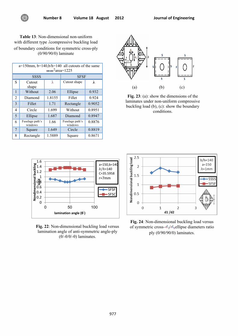
4.5-Effect of lamination angle:
It is shown from fig (22), in the case of SFSC the buckling load increase when
varies from 10 to 45 and then decrease when change from 45 to 80, but it's shown the oppsite in SFSF. The maximum buckling
load in SFSF and SFSC is at =80 and =45 respectively, while the minimum
buckling load is at=45 and =10 respectively. It′s worth mentioning that The buckling load in SFSF is higher than other case because of BC′S effects.
5. Biaxial non-uniform compressive buckling load with elliptical cutout as shown in fig (23.a) and with the boundary conditions as shown in fig (23.b,c):-
The non-dimensional buckling load =
5.1-Effect of cutout shape:
From the results listed in table (13), it can be observed that inserting cutout to the plate doesn’t always decrease the buckling load as in the case of SFSF, and that the buckling load could be increase or decrease with changing the cutout shape in a sequence depends on the boundary conditions type. The buckling load in SSSS is higher than SFSF because of boundary conditions
effect.
5.2-Effect of ellipse diameters ratio:
Fig (24) shows that in SSSS the buckling load increase with percentage reaches to 13.6% when a/b varies from o.5 to 1 then
it decrease when a/b varies from 1 to 2, on the other hand in SFSF the buckling load increase with percentage reaches to 7.2%
when a/b varies from o.5 to 1.5 then it decrease when a/b varies from 1.5 to 2. It′s worth mentioning the buckling load in SSSS is higher than SFSF, because of B.C′S.
effect.
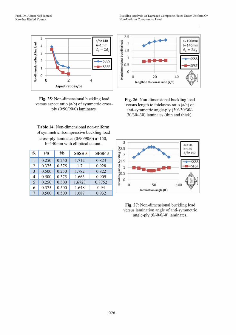
5.3-Effect of aspect ratio:
Buckling Analysis Of Damaged Composite Plates Under Uniform Or Non-Uniform Compressive Load
Prof. Dr. Adnan Naji Jameel Kawther Khalid Younus
ج
970
Fig (25) show the buckling load decrease with high percentage reaches to 55% and 69% in SSSS and SFSF when a/b increase. It′s worth mentioning the buckling load in SSSS is higher than SFSF, because of B.C′S. effect.
5.4-Effect of cutout position:
From the results listed in table (14), it can be observed that in SSSS as the cutout move in the vertical direction or the diagonal direction toward the center the buckling load increase, but the buckling load increase then decrease when the cutout move in the horizontal direction toward the center. On the other hand, in SFSF the buckling load decrease as the cutout move in the diagonal direction toward the center, but the buckling load decrease then increase when the cutout move in the vertical or horizontal direction toward the center The movement directions of cutout and the dimensions are shown in fig(23.a). The buckling load in SSSS is higher than other case because of B.C′S. effect. The maximum buckling load in SSSS and the minimum in SFSF is at (e/a=0.5, f/b=0.25), while the minimum in SSSS and the maximum in SFSF is at (e/a=0.375,
f/b=0.5).
5.5-Effect of length to thickness ratio (a/h):
In fig.(26), it can be observed that the buckling load decrease with percentage range (1.8% - 9.7) and (0.8% - 5.4%) for SSSS and SFSF respectively when a/h increase, but it was shown the opposite meaning because of the effect of non-dimensional value on buckling load. The buckling load in SSSS is higher than other
case because of B.CS effects.
5.6-Effect of lamination angle:
It is shown from fig (27), in the case of SSSS the buckling load increase when
varies from 10 to 45 and then decrease when change from 45 to 80, but it's shown the oppsite in SFSF. The maximum buckling
load in SSSS and SFSF is at =45 and
=80 respectively, while the minimum buckling load is at=10 and =45
respectively. It′s worth mentioning that the buckling load in SSSS is higher than other case because of BC′S effects.
Conclusion
This study considers the buckling analysis of cross-ply and angle-ply damaged laminates with various B.C’S. From the present study, the following conclusions can
be made:
1. It was noted that inserting cutout to the plate doesn’t always decreases the buckling loads.
2. Changing the cutout shape (for the same cutout area) change the buckling load with small percentage (under 13%)
3. It was noted that when the cutout size increase, the buckling load doesn’t always decrease. The conventional wisdom is that, as the cutout size increase, the plates lose more materials and consequently lose more bending stiffness. The buckling loads are therefore expected to decrease as the cutout size increase, but sometimes and contrary to expectation, increasing the cutout size could increase the buckling load (anomalous buckling behavior) because of the strong boundary conditions (clamped rather than simply supported boundaries). i.e. losing more materials decrease the buckling load, but the strong boundary condition increase the buckling load. Thus, which effects become dominant will determine the increase or decrease of buckling load. The increase or decrease occurs with percentage range (0.9% - 21%).
4. When the cutout move toward the center in a direction parallel to the x-axis or y-axis or diagonal axis, in general the buckling load increase with percentage range (5% - 40%)
5. In general, as the aspect ratio increases, the critical buckling load of laminated plate decreases with high percentage
Journal of Engineering Volume 18 August 2012 Number 8
971
range (40% - 77%) in all types of compressive loads.
6. It was noted that different thickness ratio affected the critical buckling load. The buckling load decrease when a/h increase.
7. The buckling load decrease when the fiber angle varies from 10 to 45 and increase when the fiber angle varies from 45 to 80. On the other hand, the opposite behavior occurs in the cases of SSSS non-uniform biaxial compressive buckling load. In the case of undamaged laminate under biaxial compressive load, critical buckling load decreases when the fiber angle increase.
:References
[1] Austin C. D. "Buckling of symmetric laminated fiberglass reinforced plastic (FRP) plates". MSC. thesis, University of Pittsburgh; 2003.
[2].William L. "Anomalous buckling characteristics of laminated metal-matrix composite plates with central square holes". NASA TP 206559; 1998.
[3].William L. "Mechanical-and thermal-buckling behavior of rectangular plates with different central cutouts". NASA TM
206542;1998.
[4] Kitsuda K. "Investigation of stress distribution on thin metal sheet with holes ". Aeronautical engineer thesis, California
institute of technology; 1935.
[5] Kumar A.R. "Buckling analysis of woven epoxy laminated composite plate". MSC thesis, National institute of
technology; 2009.
[6] Lee Y.J., Lin H.J. and Lin C.C. "A study on the buckling behavior of an orthotropic square plate with a central circular hole" J composite structures 1989;13: 173-188.
[7] Pradumna S. and Bandyopadhyay J.N. "Static buckling analysis of laminated composite plates with a central circular
cutout using a higher-order element". J Int. J. of applied mechanics and engineering 2005; 11: 1-8. [8] Teh Hu H. and Lin B. "Buckling optimization of symmetrically laminated plates with various geometries and end conditions". J composite science and technology 1995;55:277-285.
[9] Tekin M. D. and Altan M. F. 1996 "The finite element analysis of buckling of laminated rectangular reinforced concrete plates with circular hole". J mathematical and computational applications 1996; 1(2):164-168. [10] Therib J.H. "An investigation of elastic buckling for perforated plates in aircraft structures" MSC. Thesis, AL-Rasheed college of engineering and science , university of technology; 2004.
[11] Reddy J.N. “Mechanics of laminated composite plates and shells: theory and analysis “. 2ed; CRC Press 2004.
[12] "Theory, analysis, and element manuals" ANSYS 13 Program.
Fig. 1 : Shell281 Geometry [12]
Table 3: Experimental unidirectional mechanical properties of fiber glass-
Polyester for case1:-
Mechanical properties
Glass-polyester
(Mpa) 25344 (Mpa) 4790.7 (Mpa) 2470
0.25
0.36
Buckling Analysis Of Damaged Composite Plates Under Uniform Or Non-Uniform Compressive Load
Prof. Dr. Adnan Naji Jameel Kawther Khalid Younus
ج
972
Table 4: Experimental unidirectional mechanical properties of fiber glass-
Polyester for case2:-
Mechanical properties
Glass-polyester
(Mpa) 23160 (Mpa) 3323 (Mpa) 2256
0.25
0.34
Fig. 2; Buckling test of laminated plate without cutout
Fig. (3.a): Circular cutout Fig. (3.b): Square cutout
Fig. (3.a.b.): Buckling test of laminated plates with cutouts
Fig. 4: The determination of buckling load (load- displacement method)
Table 5: Dimensionless buckling load [ = * / * ] of SFSF laminates
Levy (%)
Finite element
(%)
Experimental
1.13 (7.49%)
1.11485 (8.73%)
1.2215
Table 6: Dimensionless buckling load [ = * / * ] of SFSF symmetric cross-
ply laminates with cutout
S.
Cutout shape
Cutout area
Finite element
(%)
Experimental
1 circle 501.76 1.589 (8.26%)
1.732
2 square 501.76 1.53 (8.7%)
1.676
Fig. 5: Show the dimensions of the laminates under uniaxial compressive buckling load.
Fig. 6: Non-dimensional buckling load versus aspect ratio (a/b) of anti-symmetric
cross-ply (0/90/0/90) laminates.

Journal of Engineering Volume 18 August 2012 Number 8
973
Table 7: Dimensionless uniaxial buckling load of symmetric and anti-symmetric cross
ply laminates for different boundary conditions
Fig. 7: Non-dimensional buckling load versus lamination angle of anti-symmetric
angle-ply (θ/-θ/θ/-θ) laminates SFSF.
Fig. 8: show the dimensions of the laminates under biaxial compressive
buckling load.
Fig. 9: Non-dimensional buckling load versus aspect ratio (a/b) of anti-symmetric cross-ply
(0/90/0/90) laminates.
Fig. 10: Non-dimensional buckling load versus lamination angle of anti-symmetric
angle-ply (θ/-θ/θ/-θ) laminates.
(a) (b) (c)
Fig. 11: (a): show the dimensions of the laminates under uniform compressive buckling load (b), (c): show the boundary
conditions.
(0/90/90/0)
(0/90/0/90)
B.C'S
0.8392 0.8541 S-F-S-F 1.0053 1.0053 S-F-S-S 1.1374 1.1502 S-F-S-C 2.6603 2.6603 S-S-S-S 4.1044 4.0852 S-S-S-C
a=b=200, b/h=200
5.8999 5.1267 S-C-S-C
Buckling Analysis Of Damaged Composite Plates Under Uniform Or Non-Uniform Compressive Load
Prof. Dr. Adnan Naji Jameel Kawther Khalid Younus
ج
974
Table 8: Dimensionless uniaxial buckling load )of symmetric and anti-symmetric cross ply laminates for different boundary
conditions
Table 9: Non-dimensional uniaxial compressive buckling load with different type of boundary conditions for symmetric cross-ply laminates
(0/90/90/0).
Fig. 12: Buckling load versus cutout length to plate width ratio (a/b) of symmetric
cross-ply (0/90/90/0) laminates.
Fig. 13: Non-dimensional buckling load versus cutout radii rounding (r) of
symmetric cross-ply (0/90/90/0) laminates.
Fig. 14: Non-dimensional buckling load versus aspect ratio (a/b) of symmetric cross-ply
(0/90/90/0) laminates.
Fig. 15: Non-dimensional buckling load versus length to thickness ratio (a/h) of anti-symmetric angle-ply (30/-30/30/-30/30/-30)
laminates (thin and thick).
(0/90/90/0)
(0/90/0/90)
B.C'S
1.3312 1.330 S-S-S-S 1.8914 1.883 S-S-S-C
a=b=200, b/h=200
2.9329 2.907 S-C-S-C
a=150, b=140, h=6mm all cutouts of the same area=1225 SFSF SCSC SSSS
Cutout shape
Cutout shape
Cutout shape
S
0.7322 Without 5.3860 Without 2.3312 Without 10.5734 Diamond 4.8637 Square 1.5853 Square 20.5623 Ellipse 4.5288 Fillet 1.5515 Fillet 30.5509 Rectangle 4.4648 Rectangle 1.5252 Circle 40.5453 Fuselage
path’s windows
3.3547 Circle 1.5384 Rectangle 5
0.5140 Square 4.3253 Fuselage path’s
windows
1.5097 Fuselage path’s
windows
6
0.5092 Fillet 4.1358 Ellipse 1.4851 Ellipse 70.5034 Circle 4.1539 Diamond 1.4523 Diamond 8
Journal of Engineering Volume 18 August 2012 Number 8
975
Fig. 16: Show the dimension of the laminates under compressive buckling load.
Table 10: Non-dimensional uniform compressive buckling load of symmetric
cross-ply laminates (0/90/90/0) with square cutout
Fig. 17: Non-dimensional buckling load versus lamination angle of anti-symmetric
angle-ply (θ/-θ/θ/-θ) laminates.
Fig 18.a: Non-dimensional buckling load versus distance between cutout center to
plate width ratio (s/b) of symmetric cross-ply (0/90/90/0) laminates.
Fig. 18.b: Non-dimensional buckling load versus distance between cutout center to
plate width ratio (s/b) of symmetric cross-ply (0/90/90/0) laminates.
0123456
0 0.5 1
Non
dimen
sion
al buckling
load
s/b
SCSC
b/h=140a=150h=1mmc=24.7
Fig. 18.c: Non-dimensional buckling load versus distance between cutout center to
plate width ratio (s/b) of symmetric cross-ply (0/90/90/0) laminates.
( ),SCSC ( ), SSSS f/b e/a S
4.4456 2.1025 0.250 0.250 14.7934 1.8961 0.375 0.375 24.6319 1.9985 0.250 0.500 34.8393 1.8219 0.375 0.500 44.8597 2.0747 0.500 0.250 54.9183 1.8555 0.500 0.375 64.9966 1.7820 0.500 0.500 7
Buckling Analysis Of Damaged Composite Plates Under Uniform Or Non-Uniform Compressive Load
Prof. Dr. Adnan Naji Jameel Kawther Khalid Younus
ج
976
(a) (b) (c)
Fig 19: (a): Show the dimensions of the laminates under non-uniform compressive buckling load (b), (c): show the boundary
conditions.
Table 11: Non-dimensional non-uniform compressive buckling load for symmetric
cross-ply (0/90/90/0) laminates
00.20.40.60.81
1.21.4
0 20 40
Non
dimen
sion
al
bucklin
g load
length to thickness ratio (a/h)
SFSFSFSC
a=150mmb=140mmC=35.5958
Fig. 20: Non-dimensional buckling load versus length to thickness ratio (a/h) of anti-symmetric angle-ply (30/-30/30/-30/30/-30)
laminates (thin and thick).
Table 12: Non-dimensional non-uniform compressive buckling load of symmetric cross-ply laminates
(0/90/90/0) a=b=140mm with fillet cutout.
0
1
2
3
4
0 1 2 3
Nondim
ensional buckling
load
Aspect ratio (a/b)
SFSFSFSC
b/h=140=1,r=7mm
Fig. 21: Non-dimensional buckling load versus aspect ratio (a/b) of symmetric cross-
ply (0/90/90/0) laminates.
SFSC SFSF f/b e/a S.
1.11 0.878 0.250 0.250 1 1.239 0.961 0.375 0.375 2 1.352 1.147 0.250 0.500 3 1.394 1.115 0.375 0.500 4 1.09 0.784 0.500 0.250 5
1.228 0.9352 0.500 0.375 6 1.377 1.07 0.500 0.500 7
a=150 mm, b=140,b/h=140 all cutouts of the same area=1225
SFSC SFSF
Cutout shape
Cutout shape
S
1.35 Without 1.23 Without 1 1.3 Rectangle 1.02 Diamond 2
1.293 Ellipse 1.005 Rectangle 3 1.256 Fillet 1.0012 Ellipse 4 1.25 Diamond 0.9365 Square 5 1.236 Circle 0.9186 Circle 6 1.227 Square 0.9184 Fillet 7
0.7884 Fuselage path’s
windows
0.524 Fuselage path’s
windows
8
Journal of Engineering Volume 18 August 2012 Number 8
977
Table 13: Non-dimensional non-uniform compressive buckling load with different type
of boundary conditions for symmetric cross-ply (0/90/90/0) laminate
00.20.40.60.81
1.21.41.6
0 50 100
Non
dimen
sion
al buckling
load
lamination angle (θْ)
SFSFSFSC
a=150,b=140=140
C=35.5958r=7mm
Fig. 22: Non-dimensional buckling load versus lamination angle of anti-symmetric angle-ply
(θ/-θ/θ/-θ) laminates.
(a) (b) (c)
Fig. 23: (a): show the dimensions of the laminates under non-uniform compressive buckling load (b), (c): show the boundary
conditions.
Fig. 24: Non-dimensional buckling load versus ellipse diameters ratio / of symmetric cross-
ply (0/90/90/0) laminates.
a=150mm, b=140,b/h=140 all cutouts of the same area=1225
SFSF SSSS
Cutout shape Cutout shape
S
0.932 Ellipse 2.06 Without 1 0.924 Fillet 1.8155 Diamond 2
0.9052 Rectangle 1.71 Fillet 3 0.8951 Without 1.699 Circle 4 0.8947 Diamond 1.687 Ellipse 5 0.8876 Fuselage path’s
windows 1.66 Fuselage path’s
windows 6
0.8819 Circle 1.649 Square 7 0.8671 Square 1.5889 Rectangle 8
Buckling Analysis Of Damaged Composite Plates Under Uniform Or Non-Uniform Compressive Load
Prof. Dr. Adnan Naji Jameel Kawther Khalid Younus
ج
978
0
1
2
3
4
5
0 2 4Non
dimen
sion
al buckling load
Aspect ratio (a/b)
SSSSSFSF
b/h=140=1mm
Fig. 25: Non-dimensional buckling load versus aspect ratio (a/b) of symmetric cross-
ply (0/90/90/0) laminates.
Table 14: Non-dimensional non-uniform compressive buckling load of symmetric
cross-ply laminates (0/90/90/0) a=150, b=140mm with elliptical cutout.
SFSF SSSS f/b e/a S.
0.823 1.712 0.250 0.250 1 0.928 1.7 0.375 0.375 2 0.822 1.782 0.250 0.500 3 0.909 1.663 0.375 0.500 4
0.8752 1.6723 0.500 0.250 5 0.94 1.648 0.500 0.375 6 0.932 1.687 0.500 0.500 7
Fig. 26: Non-dimensional buckling load versus length to thickness ratio (a/h) of anti-symmetric angle-ply (30/-30/30/-30/30/-30) laminates (thin and thick).
Fig. 27: Non-dimensional buckling load versus lamination angle of anti-symmetric
angle-ply (θ/-θ/θ/-θ) laminates.