Embed Size (px)
Citation preview
INTERNATIONAL JOURNAL OF PROFESSIONAL ENGINEERING STUDIES Volume VIII /Issue 1 / JAN 2017
IJPRES
BUCK CONVERTER BASED STARTER AND SPEED
CONTROLLER FOR A DC MOTOR M.Chittaranjan, (M.tech), Email Id: [email protected]
P.Deepak Reddy, M.tech,(Ph.D), Assoc.Prof, Email Id: [email protected]
LakiReddy Balireddy College of Engineering,L.B.Reddy Nagar,Mylavaram,Pin:521230
ABSTRACT :
In this paper Speed control of dc motor is achieved with smooth starter by using buck
converter. The reference speed profileis given to the controller which provides the desired
voltage profile thatmust be tracked by the output voltage of the Buck powerconverter. In
order to assure the latter, a control at the lowlevel is designed, considering a PI control for the
innercurrent loop and a proportional integral control for the outer voltage loop. The controller
is tested through experiments using MATLAB Simulink.The obtained results show that the
desired the voltage profile is well tracked under abrupt variations in the system
parametersand that the controller is robust in such operation conditions
Keywords: Smooth Starter, DC/DC Buck Power Converter, DC Motor, Proportional-Integral (PI) Control.
***-----------------------------------------------***
I. INTRODUCTION
DC motors are widely used in systems with high
precision control requirements. Thus, rolling mills,
double-hulled tankers, and high precision digital
tools can be mentioned as examples of such
systems. Generally, to control the step less velocity
and smoothness, adjustment of the armature
voltage of the motor is used while, certainly,
applying PWM signals with respect to the motor
input voltage is one of the methods most employed
to drive a DC motor. However, the underlying hard
switching strategy causes an unsatisfactory
dynamic behavior, producing abrupt variations in
the voltage and current of the motor. Power
converters, which allow the smooth start of a DC
motor by applying the required voltage.
A large number of motors are being used for
general purposes in our surroundings from house-
hold equipment to machine tools in industrial
facilities. The electric motor is now a necessary and
indispensable source of power in many industries.
The function and the performance required for
these motors are wide-ranging. When focusing
attention on the speed control segment of the motor
market, servo and stepping motors control their
speed with a pulse train, while the induction motor
and the brushless DC motor control speed with an
external resistor and/or DC voltage. This article
explains the structure, the speed control principle,
INTERNATIONAL JOURNAL OF PROFESSIONAL ENGINEERING STUDIES Volume VIII /Issue 1 / JAN 2017
IJPRES
and the features of the following three product
groups that can control the speed relatively easily
by using an analog input. x AC speed control motor
x Brushless DC motor unit x Inverter unit
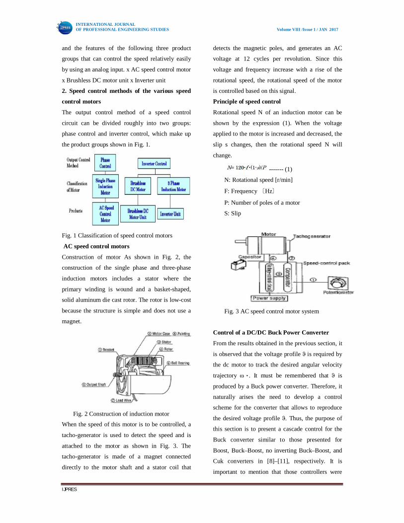
2. Speed control methods of the various speed
control motors
The output control method of a speed control
circuit can be divided roughly into two groups:
phase control and inverter control, which make up
the product groups shown in Fig. 1.
Fig. 1 Classification of speed control motors
AC speed control motors
Construction of motor As shown in Fig. 2, the
construction of the single phase and three-phase
induction motors includes a stator where the
primary winding is wound and a basket-shaped,
solid aluminum die cast rotor. The rotor is low-cost
because the structure is simple and does not use a
magnet.
Fig. 2 Construction of induction motor
When the speed of this motor is to be controlled, a
tacho-generator is used to detect the speed and is
attached to the motor as shown in Fig. 3. The
tacho-generator is made of a magnet connected
directly to the motor shaft and a stator coil that
detects the magnetic poles, and generates an AC
voltage at 12 cycles per revolution. Since this
voltage and frequency increase with a rise of the
rotational speed, the rotational speed of the motor
is controlled based on this signal.
Principle of speed control
Rotational speed N of an induction motor can be
shown by the expression (1). When the voltage
applied to the motor is increased and decreased, the
slip s changes, then the rotational speed N will
change.
------- (1)
N: Rotational speed [r/min]
F: Frequency 〔Hz〕
P: Number of poles of a motor
S: Slip
Fig. 3 AC speed control motor system
Control of a DC/DC Buck Power Converter
From the results obtained in the previous section, it
is observed that the voltage profile ϑ is required by
the dc motor to track the desired angular velocity
trajectory ω∗. It must be remembered that ϑ is
produced by a Buck power converter. Therefore, it
naturally arises the need to develop a control
scheme for the converter that allows to reproduce
the desired voltage profile ϑ. Thus, the purpose of
this section is to present a cascade control for the
Buck converter similar to those presented for
Boost, Buck–Boost, no inverting Buck–Boost, and
Cuk converters in [8]–[11], respectively. It is
important to mention that those controllers were
INTERNATIONAL JOURNAL OF PROFESSIONAL ENGINEERING STUDIES Volume VIII /Issue 1 / JAN 2017
IJPRES
only designed for the regulation task. In contrast to
those controllers, this section gives the solution for
the voltage trajectory tracking task of the Buck
converter output.
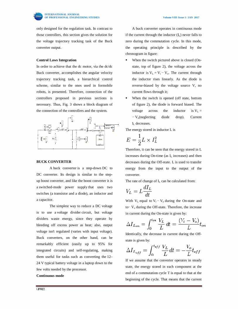
Control Laws Integration
In order to achieve that the dc motor, via the dc/dc
Buck converter, accomplishes the angular velocity
trajectory tracking task, a hierarchical control
scheme, similar to the ones used in formobile
robots, is presented. Therefore, connection of the
controllers proposed in previous sections is
necessary. Thus, Fig. 3 shows a block diagram of
the connection of the controllers and the system.
BUCK CONVERTER
A buck converter is a step-down DC to
DC converter. Its design is similar to the step-
up boost converter, and like the boost converter it is
a switched-mode power supply that uses two
switches (a transistor and a diode), an inductor and
a capacitor.
The simplest way to reduce a DC voltage
is to use a voltage divider circuit, but voltage
dividers waste energy, since they operate by
bleeding off excess power as heat; also, output
voltage isn't regulated (varies with input voltage).
Buck converters, on the other hand, can be
remarkably efficient (easily up to 95% for
integrated circuits) and self-regulating, making
them useful for tasks such as converting the 12–
24 V typical battery voltage in a laptop down to the
few volts needed by the processor.
Continuous mode
A buck converter operates in continuous mode
if the current through the inductor (IL) never falls to
zero during the commutation cycle. In this mode,
the operating principle is described by the
chronogram in figure:
When the switch pictured above is closed (On-
state, top of figure 2), the voltage across the
inductor is VL = Vi − Vo. The current through
the inductor rises linearly. As the diode is
reverse-biased by the voltage source V, no
current flows through it;
When the switch is opened (off state, bottom
of figure 2), the diode is forward biased. The
voltage across the inductor is VL =
− Vo(neglecting diode drop). Current
IL decreases.
The energy stored in inductor L is
Therefore, it can be seen that the energy stored in L
increases during On-time (as IL increases) and then
decreases during the Off-state. L is used to transfer
energy from the input to the output of the
converter.
The rate of change of IL can be calculated from:
With VL equal to Vi − Vo during the On-state and
to− Vo during the Off-state. Therefore, the increase
in current during the On-state is given by:
Identically, the decrease in current during the Off-
state is given by:
If we assume that the converter operates in steady
state, the energy stored in each component at the
end of a commutation cycle T is equal to that at the
beginning of the cycle. That means that the current
INTERNATIONAL JOURNAL OF PROFESSIONAL ENGINEERING STUDIES Volume VIII /Issue 1 / JAN 2017
IJPRES
IL is the same at t=0 and at t=T (see figure 4).
Therefore,
So we can write from the above equations:
It is worth noting that the above
integrations can be done graphically: In figure
4, is proportional to the area of the
yellow surface, and to the area of the
orange surface, as these surfaces are defined by the
inductor voltage (red) curve. As these surfaces are
simple rectangles, their areas can be found
easily: for the yellow rectangle
and − Votoff for the orange one. For steady state
operation, these areas must be equal.
As can be seen on figure 4, and
. D is a scalar called the duty
cycle with a value between 0 and 1. This yields
From this equation, it can be seen that the
output voltage of the converter varies linearly with
the duty cycle for a given input voltage. As the
duty cycle D is equal to the ratio between tOn and
the period T, it cannot be more than 1.
Therefore, . This is why this converter
is referred to as step-down converter.
So, for example, stepping 12 V down to
3 V (output voltage equal to a fourth of the input
voltage) would require a duty cycle of 25%, in our
theoretically ideal circuit.
Discontinuous mode
In some cases, the amount of energy
required by the load is small enough to be
transferred in a time lower than the whole
commutation period. In this case, the current
through the inductor falls to zero during part of the
period. The only difference in the principle
described above is that the inductor is completely
discharged at the end of the commutation cycle.
This has, however, some effect on the previous
equations.
Controlling Circuit:
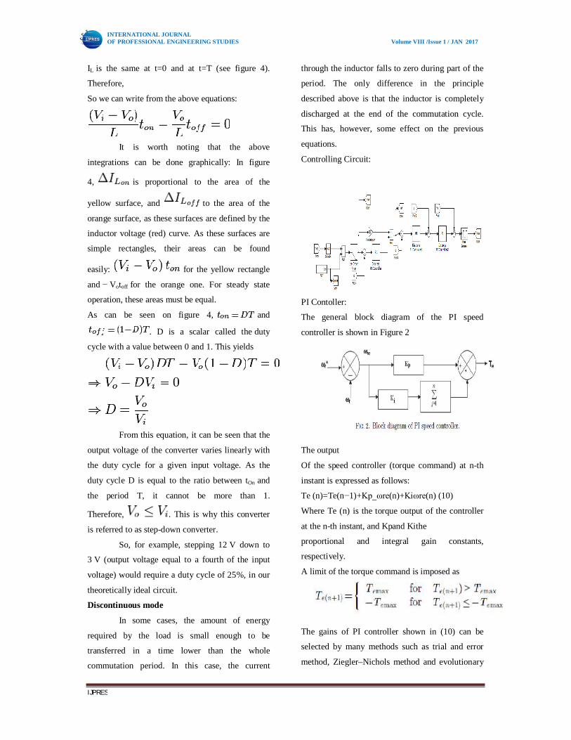
PI Contoller:
The general block diagram of the PI speed
controller is shown in Figure 2
The output
Of the speed controller (torque command) at n-th
instant is expressed as follows:
Te (n)=Te(n−1)+Kp_ωre(n)+Kiωre(n) (10)
Where Te (n) is the torque output of the controller
at the n-th instant, and Kpand Kithe
proportional and integral gain constants,
respectively.
A limit of the torque command is imposed as
The gains of PI controller shown in (10) can be
selected by many methods such as trial and error
method, Ziegler–Nichols method and evolutionary
INTERNATIONAL JOURNAL OF PROFESSIONAL ENGINEERING STUDIES Volume VIII /Issue 1 / JAN 2017
IJPRES
techniques-based searching. The numerical values
of these controller gains depend on the ratings of
the motor.
Advantages and disadvantages
The integral term in a PI controller causes the
steady-state error to reduce to zero, which is not the
case for proportional-only control in general. The
lack of derivative action may make the system
more steady in the steady state in the case of noisy
data. This is because derivative action is more
sensitive to higher-frequency terms in the inputs.
Without derivative action, a PI-controlled system is
less responsive to real (non-noise) and relatively
fast alterations in state and so the system will be
slower to reach setpoint and slower to respond to
perturbations than a well-tuned PID system may be.
Integral Action and PI Control
Like the P-Only controller, the Proportional-
Integral (PI) algorithm computes and transmits a
controller output (CO) signal every sample time, T,
to the final control element (e.g., valve, variable
speed pump). The computed CO from the PI
algorithm is influenced by the controller tuning
parameters and the controller error, e(t).
PI controllers have two tuning parameters to adjust.
While this makes them more challenging to tune
than a
P-Only controller, they are not as complex as the
three parameter PID controller.
Integral action enables PI controllers to eliminate
offset, a major weakness of a P-only controller.
Thus, PI controllers provide a balance of
complexity and capability that makes them by far
the most widely used algorithm in process control
applications.
The PI Algorithm
While different vendors cast what is essentially the
same algorithm in different forms, here we explore
what is variously described as the dependent, ideal,
continuous, position form:
Where:
CO = controller output signal (the wire out)
CObias = controller bias or null value; set by
bumpless transfer as explained below
e(t) = current controller error, defined as SP – PV
SP = set point
PV = measured process variable (the wire in)
Kc = controller gain, a tuning parameter
Ti = reset time, a tuning parameter
The first two terms to the right of the equal sign are
identical to the P-Only controller referenced at the
top of this article. The integral mode of the
controller is the last term of the equation. Its
function is to integrate or continually sum the
controller error, e(t), over time. Some things we
should know about the reset time tuning parameter,
Ti: It provides a separate weight to the integral
term so the influence of integral action can be
independently adjusted. It is in the denominator so
smaller values provide a larger weight to (i.e.
increase the influence of) the integral term. It has
units of time so it is always positive.
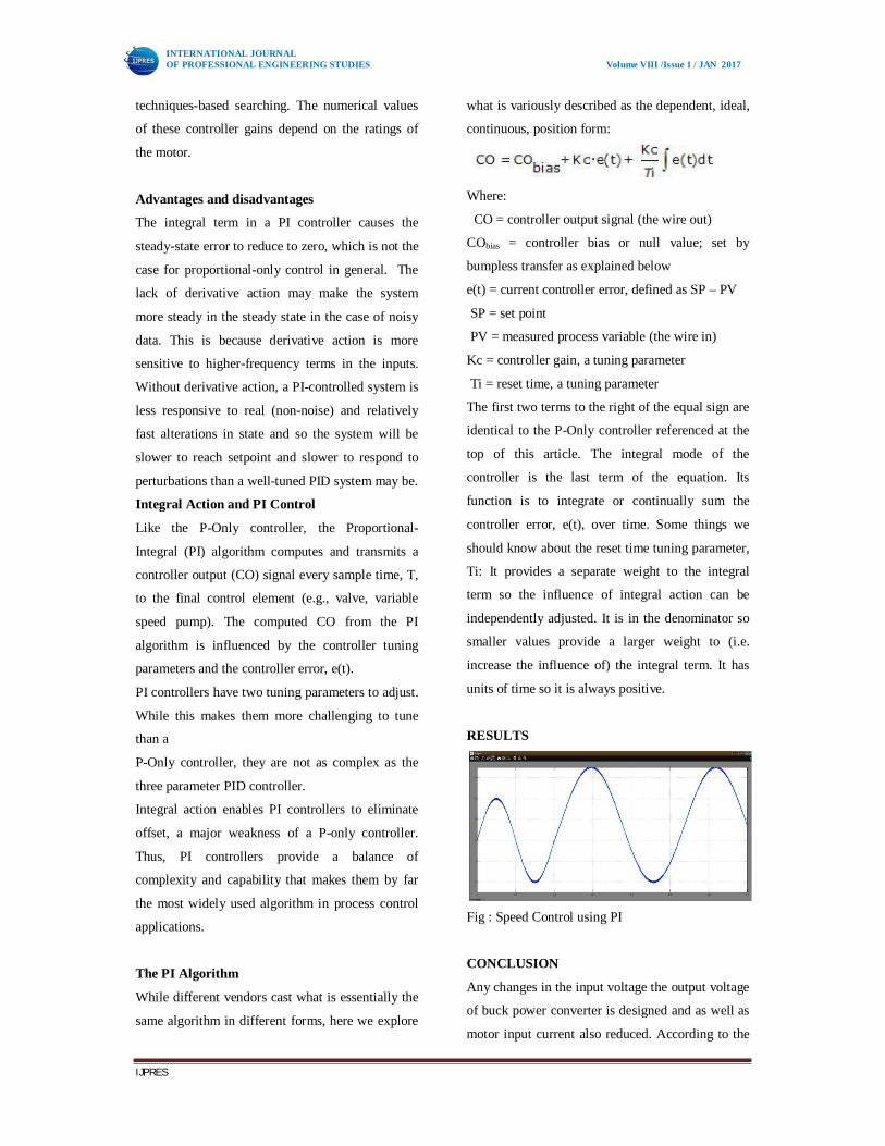
RESULTS
Fig : Speed Control using PI
CONCLUSION
Any changes in the input voltage the output voltage
of buck power converter is designed and as well as
motor input current also reduced. According to the
INTERNATIONAL JOURNAL OF PROFESSIONAL ENGINEERING STUDIES Volume VIII /Issue 1 / JAN 2017
IJPRES
experimental results the main purpose of this paper
was successfully achieved. The obtained results
have shown that any variation in speed and torque
the voltage cannot be varied. The performance
evaluation can be done based on the comparison
between conventional and proposed simulation
results. The peak overshoot can be minimized by
proposed system (PI). The peak overshoot in
proposed PI system can be minimized to some
extent. So that oscillation in speed can be limited. It
is important to underline that these types of abrupt
variations do not happen in practice at the same
time, or such large variations regarding their
nominal values. So that any change in supply
voltage, torque variations or load changes buck
power converter can limit the input voltage current
and speed control is also possible by proposed
simulink system.
REFERENCES
[1] Ramon Siiva- Ortigoza, Victor Manuel
Heenandez – Guzman,”DC/DC Buck Power
Converter as a Smooth Starter for a DC Motor
Based on a Hierarchical Control” in
http://ieeexplore.ieee.org.
[2] F. Antritter, P. Maurer, and J. Reger, “Flatness
based control of a buckconverterdriven DC motor,”
in Proc. 4th IFAC Symp.Mechatron.Syst.,
Heidelberg, Germany, Sep. 12–14, 2006, pp. 36–
41.
[3] S. E. Lyshevski, Electromechanical Systems,
Electric Machines, and AppliedMechatronics. Boca
Raton, FL, USA: CRC Press, 1999.
[4] J. Linares-Flores and H. Sira-Ram´ırez, “A
smooth starter for a DC machine:A flatness based
approach,” in Proc. 1st Int. Conf. Electr. Electron.
Eng., Acapulco, Mexico, Sep. 8–10, 2004, pp. 589–
594.
[5] J. Linares-Flores and H. Sira-Ram´ırez,
“Sliding mode-delta modulationGPI control of a
DC motor through a buck converter,” in Proc. 2nd
IFACSymp. Syst., Struct.Control, Oaxaca, Mexico,
Dec. 8–10, 2004, pp. 405–409.
[6] J. Linares-Flores and H. Sira-
Ram´ırez,“DCmotor velocity control throughaDC-
to-DC power converter,” in Proc. IEEE 43rd
Conf.Decision Control,Atlantis, The Bahamas,
Dec. 14–17, 2004, vol. 5, pp. 5297–5302.
[7] R.Ortega, A. Loria, P. J. Nicklasson, andH.
Sira-Ram ı́rez,Passivity-BasedControl of Euler-
Lagrange Systems. London, U.K.: Springer-Verlag,
1998.
[8] J. Linares-Flores, “Control suave de velocidad
de motores de CD medianteconvertidores de
potencia CD/CD,” Ph.D. dissertation, Secci´on de
Mecatr´onicadelDepartamento de
Ingenier ı́aEl´ectrica del CINVESTAVIPN,Mexico
City, Mexico, 2006.
[9] J. Linares-Flores, A. Orantes-MolinayA.
Antonio-Garc´ıa, “Arranquesuave paraun motor de
CD a trav´es de un convertidorreductor CD-
CD,”Ing. Investigaci´onTecnol., vol. 12, no. 2, pp.
137–148, Oct. 2011.
INTERNATIONAL JOURNAL OF PROFESSIONAL ENGINEERING STUDIES Volume VIII /Issue 1 / JAN 2017
IJPRES
[10] H. El Fadil and F. Giri, “Accounting of DC-
DC power converter dynamicsin DC motor velocity
adaptive control,” in Proc. IEEE Int. Conf.
ControlAppl., Munich, Germany, Oct. 4–6, 2006,
pp. 3157–3162.
[11] R. Sureshkumar and S. Ganeshkumar,
“Comparative study of proportionalintegral and
backstepping controller for buck converter,” in
Proc. Int. Conf.Emerging Trends Electr.Comput.
Technol., Tamil Nadu, India, Mar. 23–24, 2011,
pp. 375–379.
[12] O. Bing¨ol and S. Pac¸aci, “A virtual
laboratory for neural network controlledDC motors
based on a DC-DC buck converter,” Int. J. Eng.
Educ.,vol. 28, no. 3, pp. 713–723, 2012.