Embed Size (px)
Citation preview
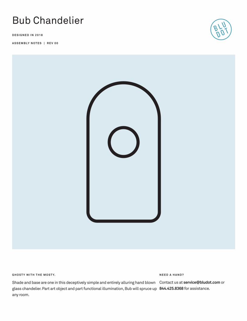
Bub ChandelierD E S I G N E D I N 2 0 1 8
A S S E M B LY N O T E S | R E V 0 0
G H O S T Y W I T H T H E M O S T Y.
Shade and base are one in this deceptively simple and entirely alluring hand blown glass chandelier. Part art object and part functional illumination, Bub will spruce up any room.
N E E D A H A N D ?
Contact us at [email protected] or 844.425.8368 for assistance.
1 | 8 4 4 . 4 2 5 . 8 3 6 8 B U B C H A N D E L I E R
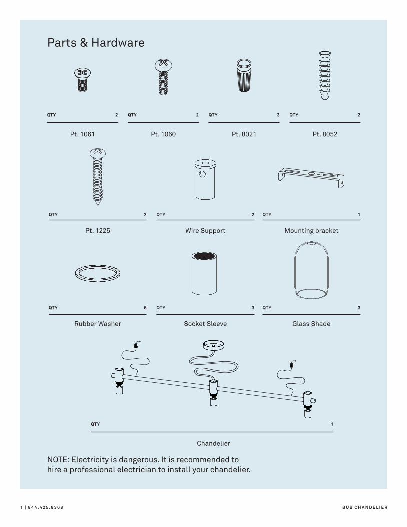
Chandelier
1QTY
Rubber Washer
Pt. 1225
6
2
QTY
QTY
Socket Sleeve
Wire Support
Glass Shade
Mounting bracket
3
2
3
1
QTY
QTY
QTY
QTY
Pt. 1061
2QTY
Pt. 1060
2QTY
Pt. 8021
QTY
Pt. 8052
2QTY3
Parts & Hardware
NOTE: Electricity is dangerous. It is recommended to hire a professional electrician to install your chandelier.
S E R V I C E @ B L U D O T. C O M | 2A S S E M B LY N O T E S
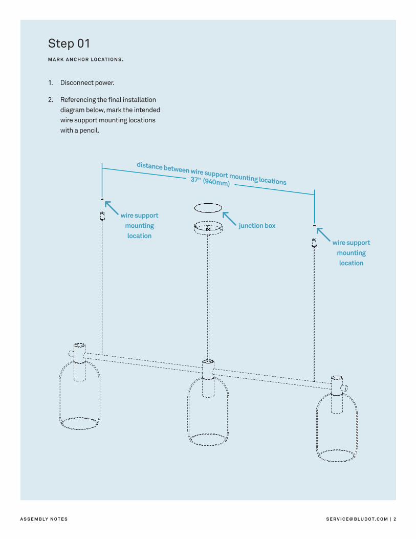
37” (940mm)
distance between wire support mounting locations
junction box
wire support mounting location
wire support mounting location
Step 01M A R K A N C H O R L O C AT I O N S .
1. Disconnect power.
2. Referencing the final installation diagram below, mark the intended wire support mounting locations with a pencil.
3 | 8 4 4 . 4 2 5 . 8 3 6 8 B U B C H A N D E L I E R
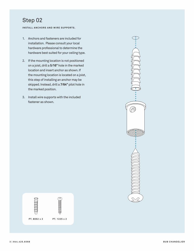
PT. 8052 x 2 PT. 1225 x 2
Step 02I N S TA L L A N C H O R S A N D W I R E S U P P O R T S .
1. Anchors and fasteners are included for installation. Please consult your local hardware professional to determine the hardware best suited for your ceiling type.
2. If the mounting location is not positioned on a joist, drill a 5/16” hole in the marked location and insert anchor as shown. If the mounting location is located on a joist, this step of installing an anchor may be skipped. Instead, drill a 7/64” pilot hole in the marked position.
3. Install wire supports with the included fastener as shown.
S E R V I C E @ B L U D O T. C O M | 4A S S E M B LY N O T E S
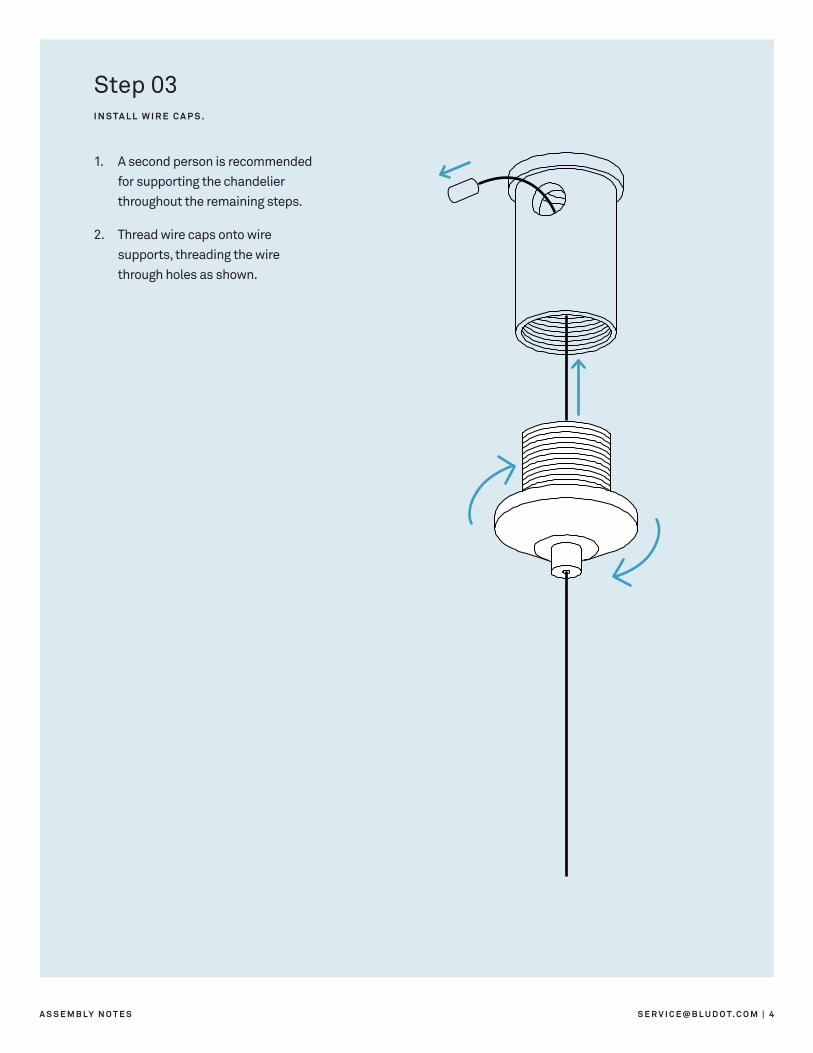
Step 03I N S TA L L W I R E C A P S .
1. A second person is recommended for supporting the chandelier throughout the remaining steps.
2. Thread wire caps onto wire supports, threading the wire through holes as shown.
5 | 8 4 4 . 4 2 5 . 8 3 6 8 B U B C H A N D E L I E R
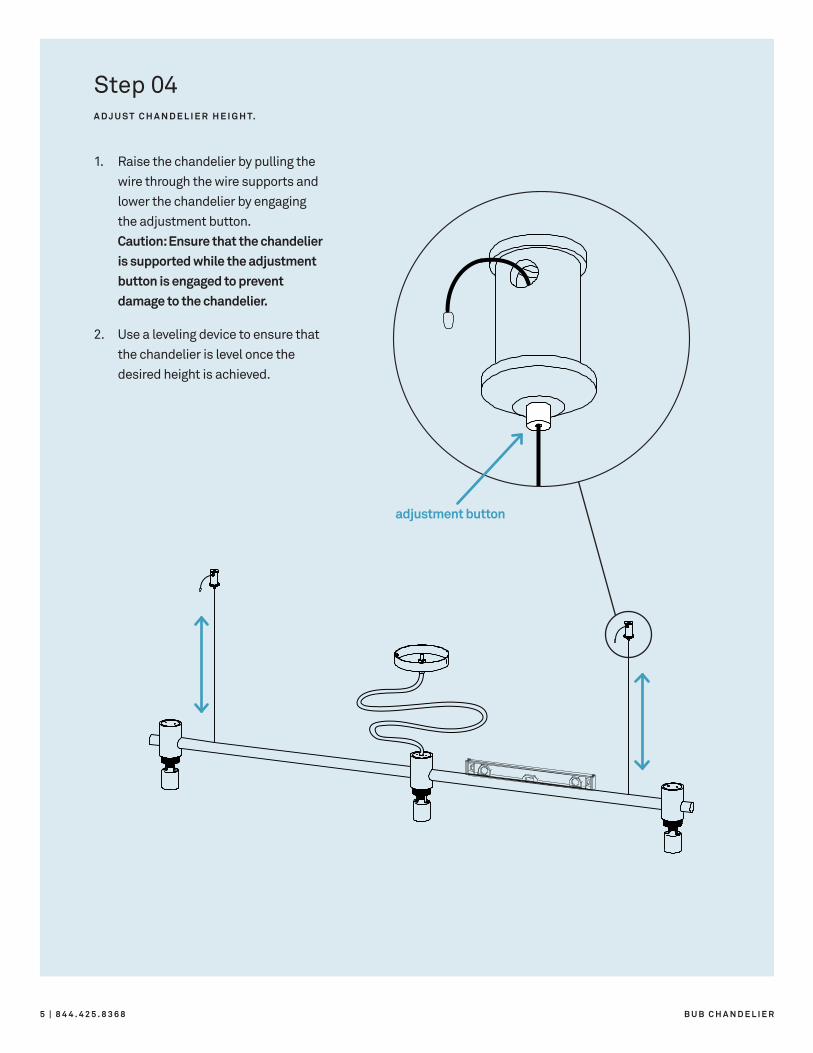
adjustment button
Step 04A D J U S T C H A N D E L I E R H E I G H T.
1. Raise the chandelier by pulling the wire through the wire supports and lower the chandelier by engaging the adjustment button. Caution: Ensure that the chandelier is supported while the adjustment button is engaged to prevent damage to the chandelier.
2. Use a leveling device to ensure that the chandelier is level once the desired height is achieved.
S E R V I C E @ B L U D O T. C O M | 6A S S E M B LY N O T E S
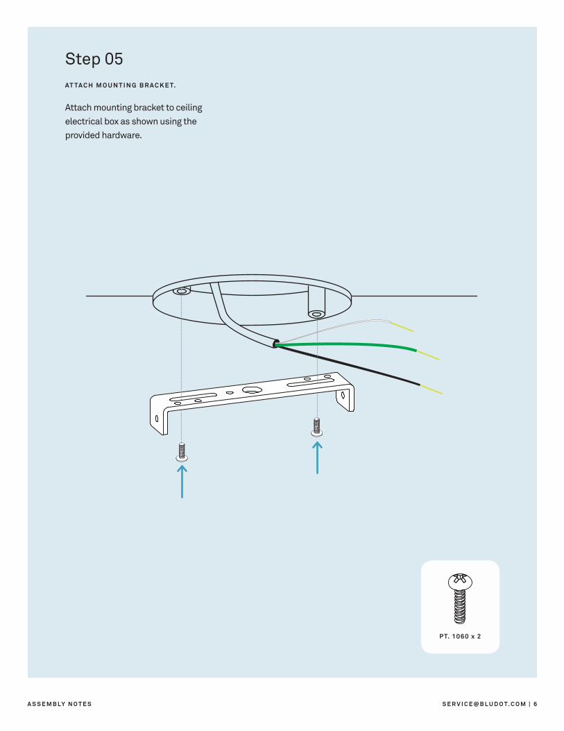
PT. 1060 x 2
Step 05AT TA C H M O U N T I N G B R A C K E T.
Attach mounting bracket to ceiling electrical box as shown using the provided hardware.
7 | 8 4 4 . 4 2 5 . 8 3 6 8 B U B C H A N D E L I E R
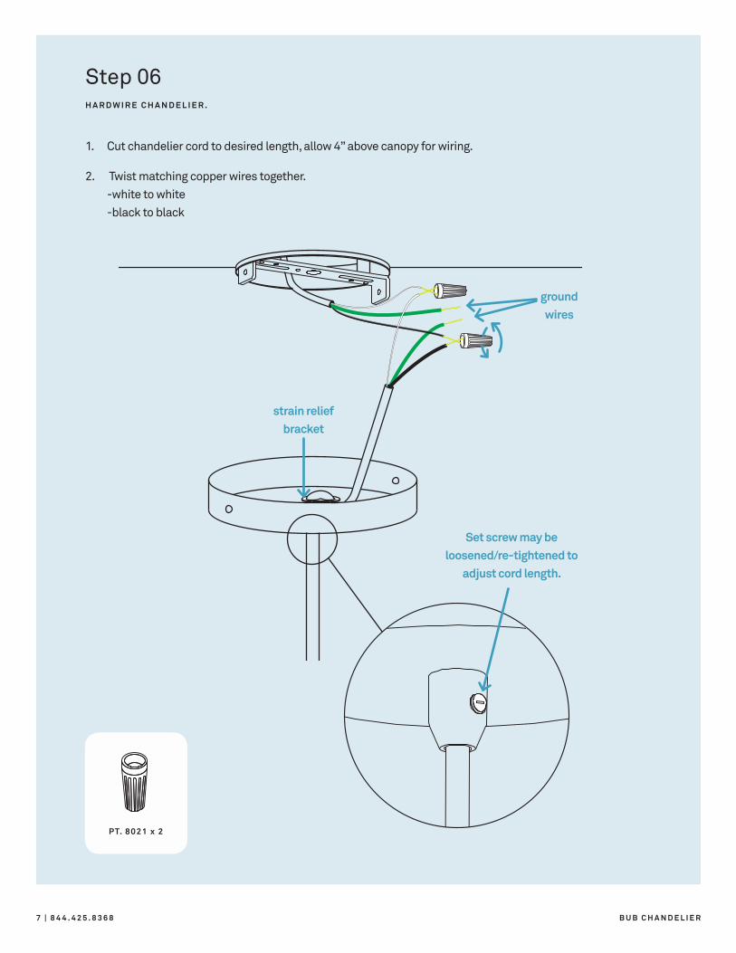
PT. 8021 x 2
strain relief bracket
ground wires
Set screw may be loosened/re-tightened to
adjust cord length.
Step 06H A R D W I R E C H A N D E L I E R .
1. Cut chandelier cord to desired length, allow 4” above canopy for wiring.
2. Twist matching copper wires together. -white to white -black to black
S E R V I C E @ B L U D O T. C O M | 8A S S E M B LY N O T E S
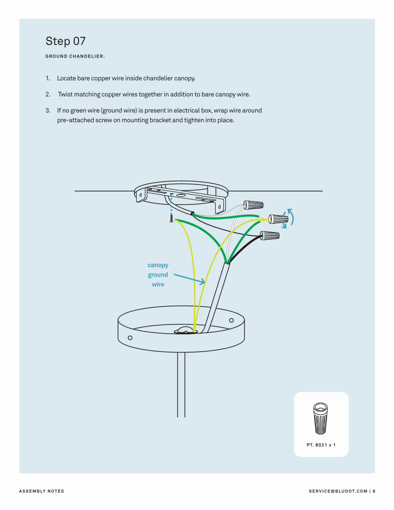
PT. 8021 x 1
Step 07G R O U N D C H A N D E L I E R .
1. Locate bare copper wire inside chandelier canopy.
2. Twist matching copper wires together in addition to bare canopy wire.
3. If no green wire (ground wire) is present in electrical box, wrap wire around pre-attached screw on mounting bracket and tighten into place.
canopy ground
wire
9 | 8 4 4 . 4 2 5 . 8 3 6 8 B U B C H A N D E L I E R
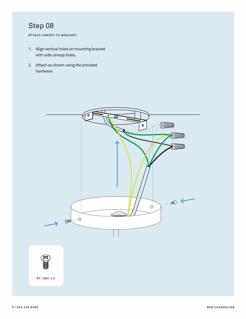
PT. 1061 x 2
Step 08AT TA C H C A N O P Y T O B R A C K E T.
1. Align vertical holes on mounting bracket with side canopy holes.
2. Attach as shown using the provided hardware.
S E R V I C E @ B L U D O T. C O M | 1 0A S S E M B LY N O T E S
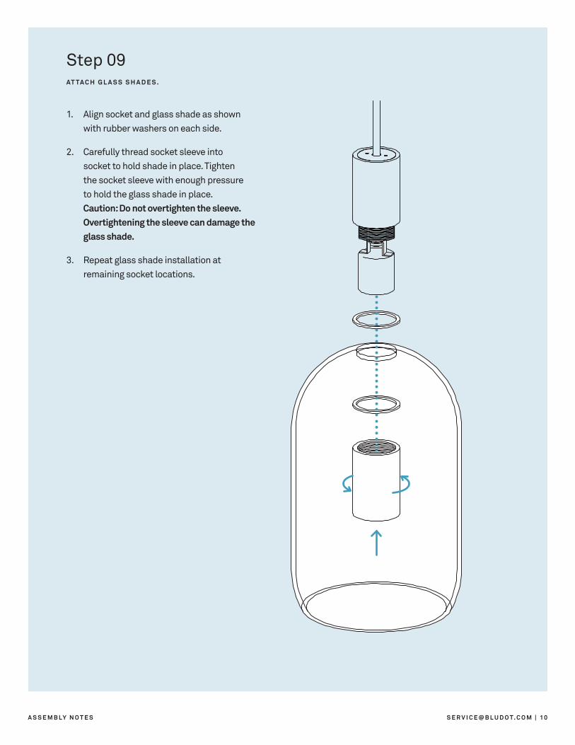
Step 09AT TA C H G L A S S S H A D E S .
1. Align socket and glass shade as shown with rubber washers on each side.
2. Carefully thread socket sleeve into socket to hold shade in place. Tighten the socket sleeve with enough pressure to hold the glass shade in place. Caution: Do not overtighten the sleeve. Overtightening the sleeve can damage the glass shade.
3. Repeat glass shade installation at remaining socket locations.
B L U D O T D E S I G N & M A N U F A C T U R I N G , I N C . D E S I G N E D I N M I N N E A P O L I S , M N
Additional Information
NOTE
We recommend using 60W G25 globe bulbs.
CLEAN
Clean powder-coated surfaces with a soft cloth or sponge using a mild detergent, such as dish soap, and warm water. Wipe completely dry with a soft cloth. Clean glass surfaces with a high quality cleaner formulated for glass products.
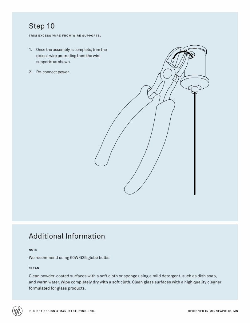
Step 10T R I M E X C E S S W I R E F R O M W I R E S U P P O R T S .
1. Once the assembly is complete, trim the excess wire protruding from the wire supports as shown.
2. Re-connect power.