Embed Size (px)
DESCRIPTION
installation guide
Citation preview
BTS3900C WCDMA Installation Guide
Issue: 06
HUAWEI TECHNOLOGIES Co., Ltd.
Date: 2013-03-08
This document is applicable to WCDMA V200R013C01/V.
Prepare for the InstallatioStructure and Clearance
Contents
Structure and Clearance Obtaining the ESN ………Installing the BTS3900C CInstalling the RRU ………Checking the DIP SwitcheInstalling the BTS3900C CChecklist for the BTS390Appendix …………………Change History …………
1
V200R014C00/V200R015C00.
on …………………………25 ……………………………
………………………………Cabinet……………………
………………………………es……………………………
567
141819Cables ……………………
0C Installation ……………………………………………………………………
19323538
1 Copyright © Huawei Technologies Co., Ltd. 2013. All rights reserved.
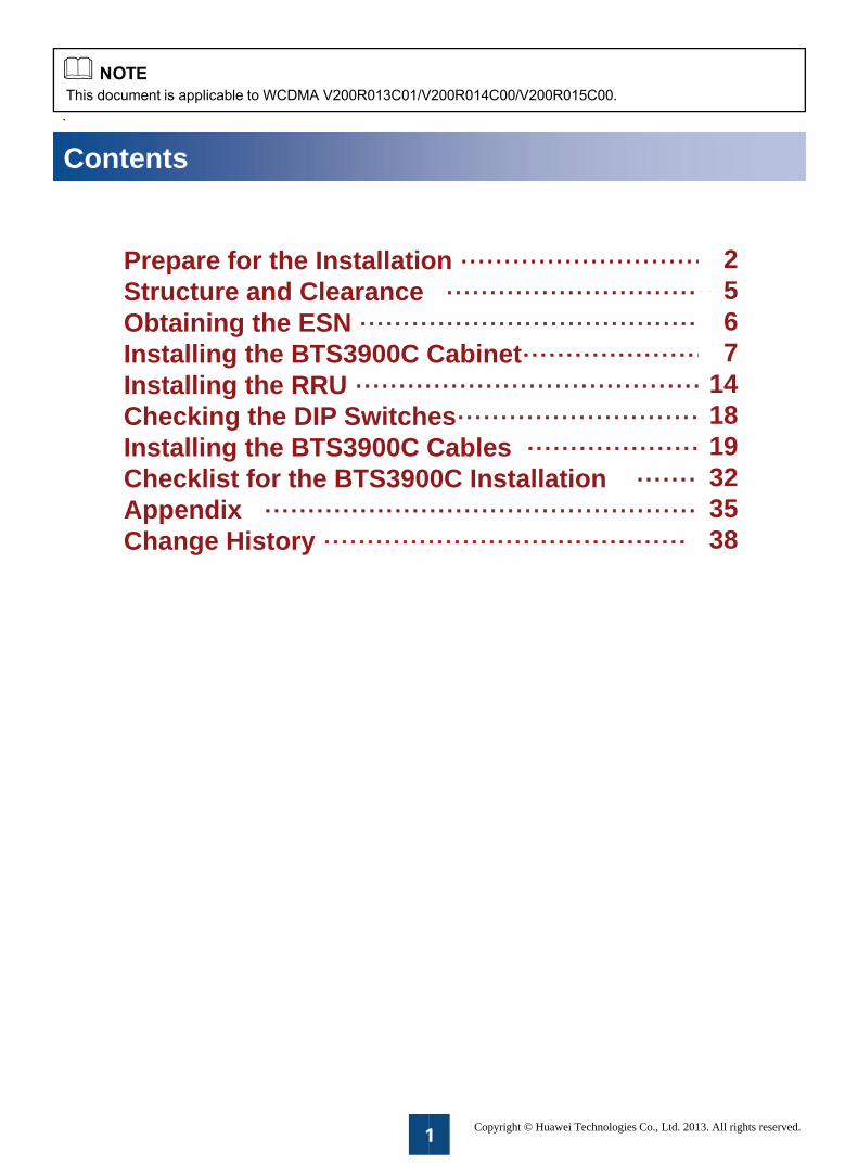
Prepare for the Installation
a Installation Procedure
Information
Star
Information installa
Install the BTS3900C
Assemble the Bcabin
Install the BInstall the BTS3900C cabinet on a wall
Install the
Install the Bcabinet on a m
Install the BTCable
Check the DIP the boards of
Checklist BTS3900C in
End
2
about the
rt
about the ation
BTS3900C net
TS3900C Install the BTS3900C
e RRU
TS3900C metal pole
Install the BTS3900C cabinet on a stand
TS3900C es
Switches on f the BBU
for the nstallation
d
2
Prepare for the Installation
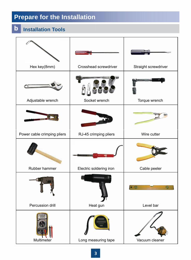
b Installation Tools
Hex key(8mm) Crosshead
Adjustable wrench Socket
Power cable crimping pliers RJ-45 crim
Rubber hammer Electric so
Percussion drill Hea
3
Multimeter Long mea
Straight screwdriverd screwdriver
t wrench Torque wrench
mping pliers Wire cutter
Cable peelerldering iron
at gun Level bar
3
suring tape Vacuum cleaner
Prepare for the Installation
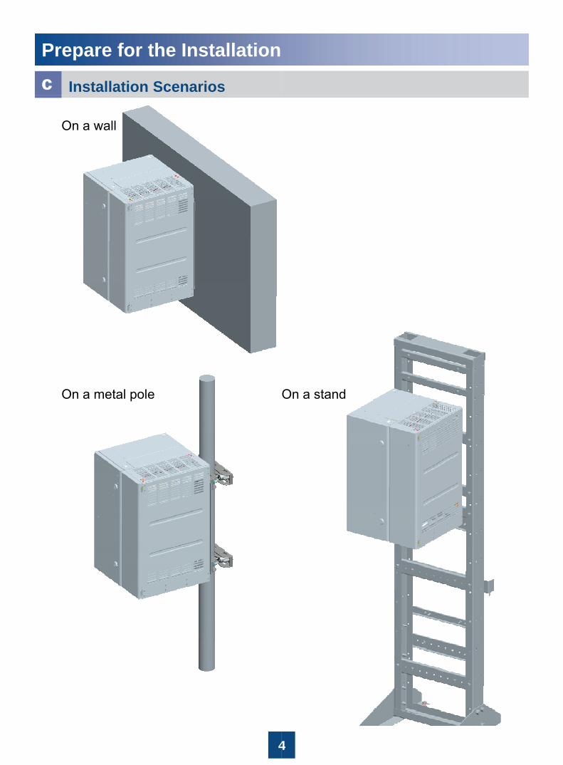
c Installation Scenarios
On a wall
On a metal pole
4
On a stand
4
Structure and Clearance
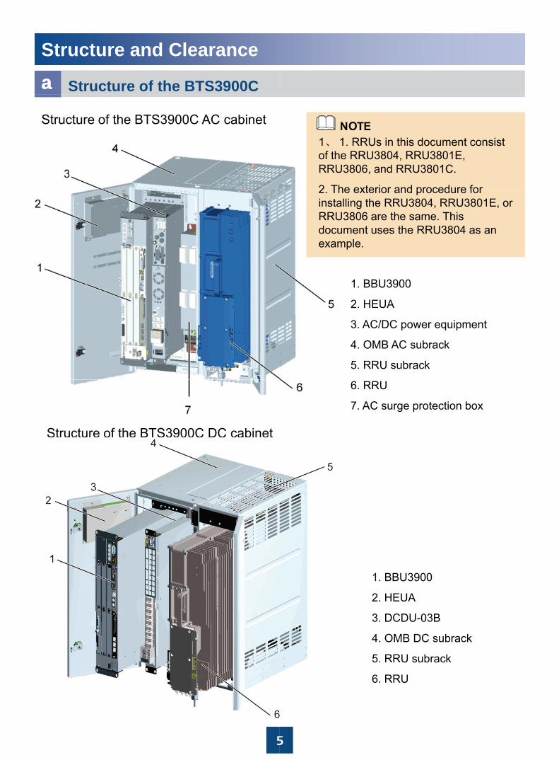
a Structure of the BTS3900C
Structure of the BTS3900C AC cabinet
Structure of the BTS3900C DC cabinet
5
1、 1. RRUs in this document consist of the RRU3804, RRU3801E, RRU3806, and RRU3801C.
2 The exterior and procedure for
1 BBU3900
2. The exterior and procedure for installing the RRU3804, RRU3801E, or RRU3806 are the same. This document uses the RRU3804 as an example.
1. BBU3900
2. HEUA
3. AC/DC power equipment
4. OMB AC subrack
5. RRU subrack
6. RRU
7. AC surge protection box
1. BBU3900
2. HEUA
3. DCDU-03B
4. OMB DC subrack
5. RRU subrack
5
6. RRU
Structure and Clearance
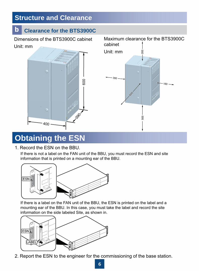
b Clearance for the BTS3900CDimensions of the BTS3900C cabinetUnit: mm
Obt i i th ESNObtaining the ESN1. Record the ESN on the BBU.
If there is not a label on the FAN unit of the Binformation that is printed on a mounting ear
If there is a label on the FAN unit of the BBUIf there is a label on the FAN unit of the BBU,mounting ear of the BBU. In this case, you minformation on the side labeled Site, as show
6
2. Report the ESN to the engineer for the
Maximum clearance for the BTS3900C cabinetUnit: mm
BBU, you must record the ESN and site of the BBU.
the ESN is printed on the label and a, the ESN is printed on the label and a must take the label and record the site wn in.
6
commissioning of the base station.
Installing the BTS3900C Ca
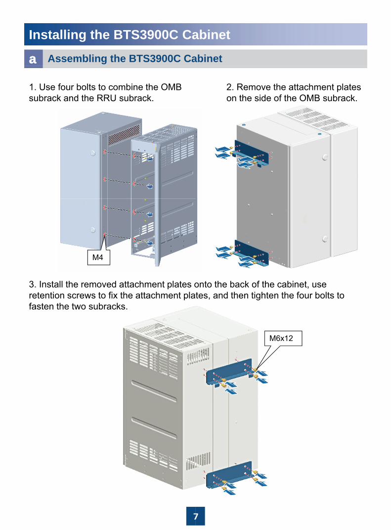
a Assembling the BTS3900C Ca
1. Use four bolts to combine the OMB subrack and the RRU subrack.
M4
3. Install the removed attachment plates oretention screws to fix the attachment plafasten the two subracks.
7
abinet
abinet
2. Remove the attachment plates on the side of the OMB subrack.
onto the back of the cabinet, use tes, and then tighten the four bolts to
M6x12
7
Installing the BTS3900C Ca
b Installing the BTS3900C Cabin
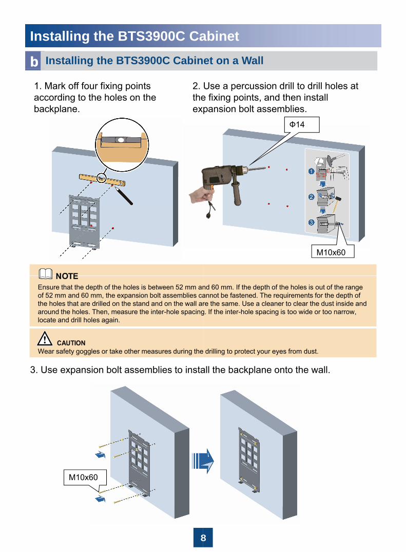
1. Mark off four fixing points according to the holes on the backplane.
2. theex
Ensure that the depth of the holes is between 52 mm anof 52 mm and 60 mm, the expansion bolt assemblies cathe holes that are drilled on the stand and on the wall araround the holes. Then, measure the inter-hole spacinglocate and drill holes again.
3. Use expansion bolt assemblies to insta
Wear safety goggles or take other measures during the
M10x60
8
abinetet on a Wall
Use a percussion drill to drill holes at e fixing points, and then install pansion bolt assemblies.
Ф14
M10x60
nd 60 mm. If the depth of the holes is out of the range annot be fastened. The requirements for the depth of re the same. Use a cleaner to clear the dust inside and g. If the inter-hole spacing is too wide or too narrow,
all the backplane onto the wall.
drilling to protect your eyes from dust.
8
Installing the BTS3900C Ca
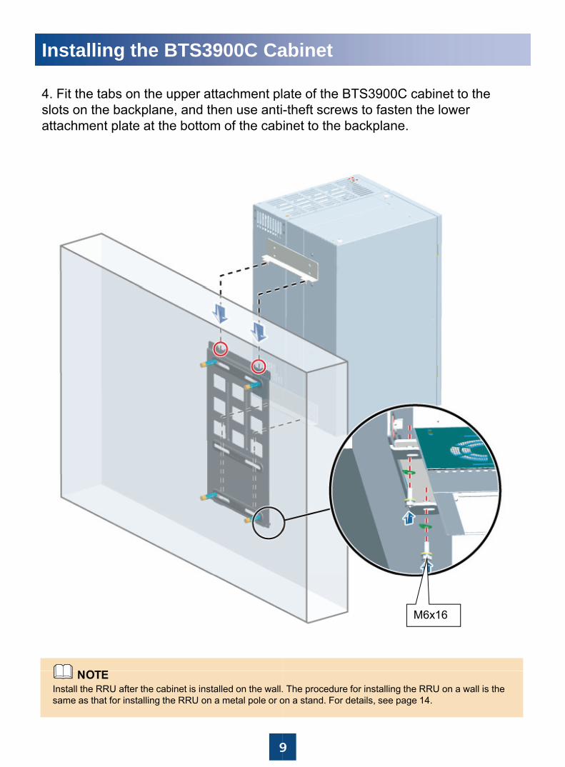
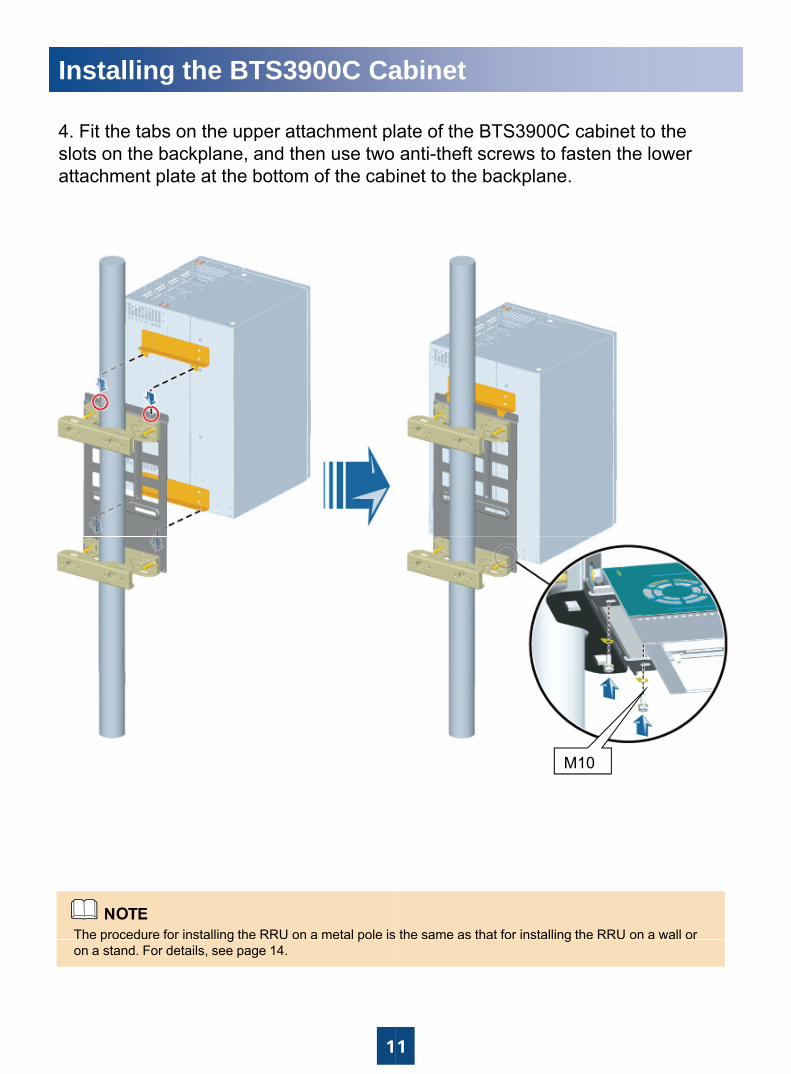
4 Fit the tabs on the upper attachment pl4. Fit the tabs on the upper attachment plslots on the backplane, and then use antiattachment plate at the bottom of the cab
9
Install the RRU after the cabinet is installed on the wall.same as that for installing the RRU on a metal pole or o
abinet
ate of the BTS3900C cabinet to theate of the BTS3900C cabinet to the -theft screws to fasten the lower inet to the backplane.
M6x16
9
. The procedure for installing the RRU on a wall is the on a stand. For details, see page 14.
Installing the BTS3900C Ca
c Installing the BTS3900C Cabin
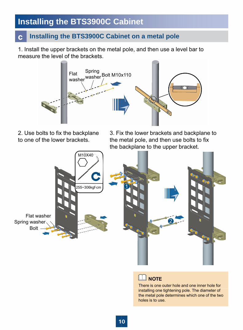
Flat washer
Spring washer Bolt M10x
1. Install the upper brackets on the metal measure the level of the brackets.
M10X40
2. Use bolts to fix the backplane to one of the lower brackets.
3. Fixthe mthe b
255~306kgf·cm
Flat washerSpring washer
Bolt
1
abinetnet on a metal pole
x110
pole, and then use a level bar to
x the lower brackets and backplane to metal pole, and then use bolts to fix backplane to the upper bracket.
There is one outer hole and one inner hole for
0
installing one tightening pole. The diameter of the metal pole determines which one of the two holes is to use.
Installing the BTS3900C Ca
4 Fit the tabs on the upper attachment pl4. Fit the tabs on the upper attachment plslots on the backplane, and then use two attachment plate at the bottom of the cab
The procedure for installing the RRU on a metal pole is
1
p g pon a stand. For details, see page 14.
abinet
ate of the BTS3900C cabinet to theate of the BTS3900C cabinet to the anti-theft screws to fasten the lower inet to the backplane.
M10
the same as that for installing the RRU on a wall or
1
g
Installing the BTS3900C Ca
d Installing the BTS3900C Cabin
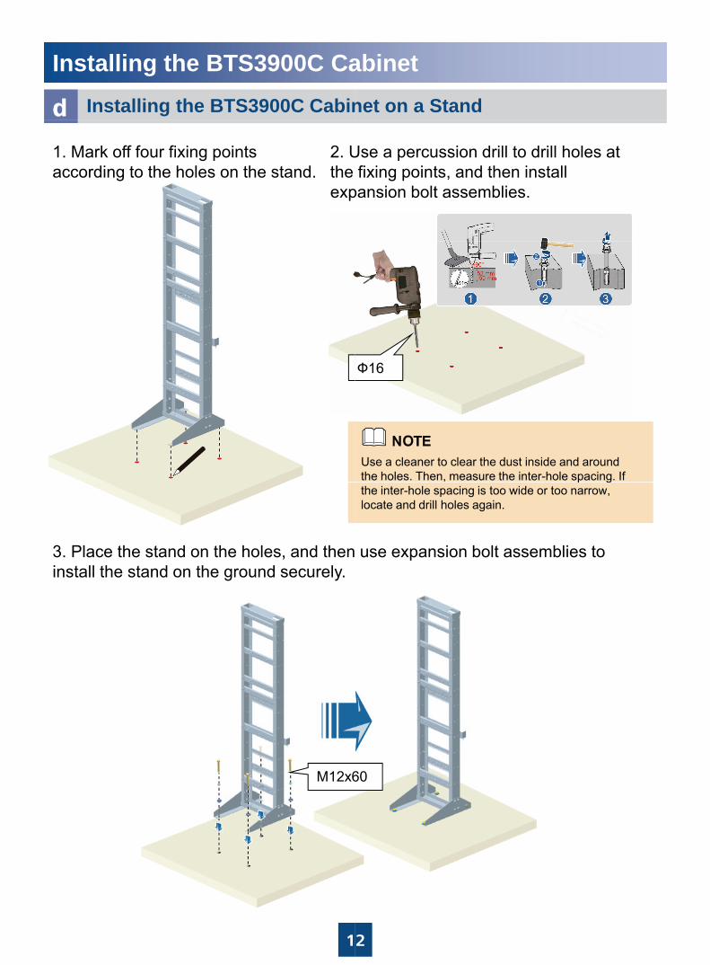
1. Mark off four fixing points according to the holes on the stand.
2. Uthe exp
3. Place the stand on the holes, and theninstall the stand on the ground securely.
M12x6
1
abinetnet on a Stand
Use a percussion drill to drill holes at fixing points, and then install
pansion bolt assemblies.
Use a cleaner to clear the dust inside and around the holes. Then, measure the inter-hole spacing. If
Ф16
p gthe inter-hole spacing is too wide or too narrow, locate and drill holes again.
use expansion bolt assemblies to
60
2
Installing the BTS3900C Ca
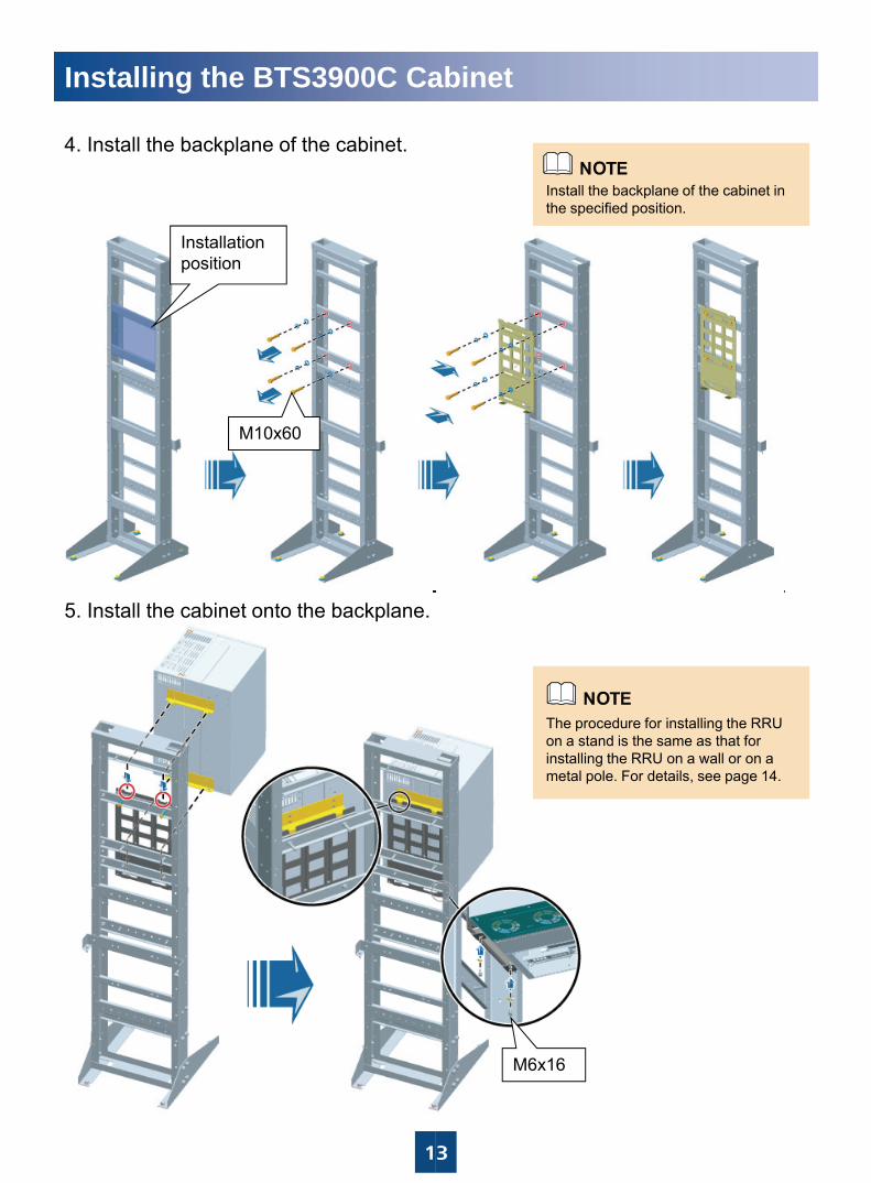
4 Install the backplane of the cabinet4. Install the backplane of the cabinet.
Installation position
M10x60
5. Install the cabinet onto the backplane.
1
abinet
Install the backplane of the cabinet in the specified position.
The procedure for installing the RRU on a stand is the same as that foron a stand is the same as that for installing the RRU on a wall or on a metal pole. For details, see page 14.
3
M6x16
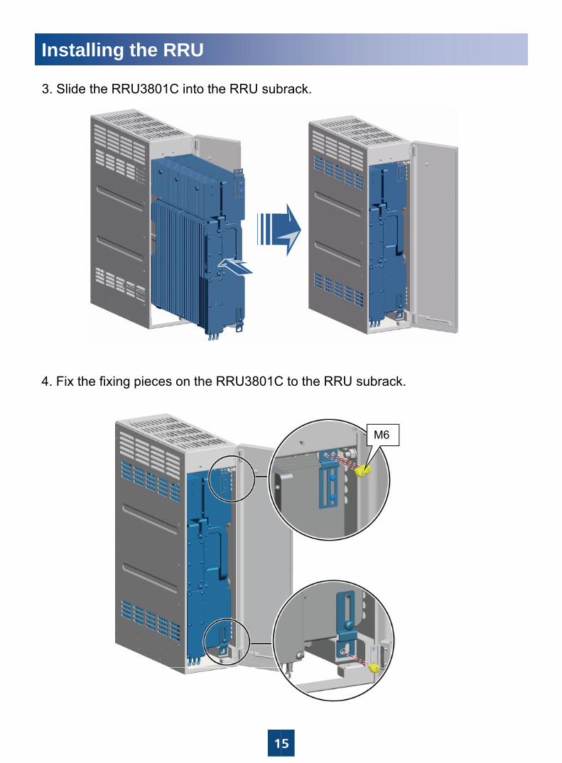
Installing the RRUInstalling the RRU3801Ca
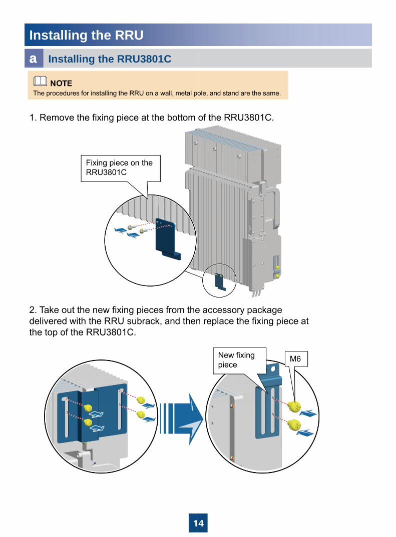
1. Remove the fixing piece at the bottom
The procedures for installing the RRU on a wall, metal po
Fixing piece on the RRU3801C
2. Take out the new fixing pieces from thedelivered with the RRU subrack, and thenthe top of the RRU3801C.p
1
of the RRU3801C.
ole, and stand are the same.
e accessory package n replace the fixing piece at
New fixing piece
M6
4
Installing the RRU
3. Slide the RRU3801C into the RRU sub
4 Fix the fixing pieces on the RRU3801C4. Fix the fixing pieces on the RRU3801C
1
brack.
C to the RRU subrackC to the RRU subrack.
M6
5
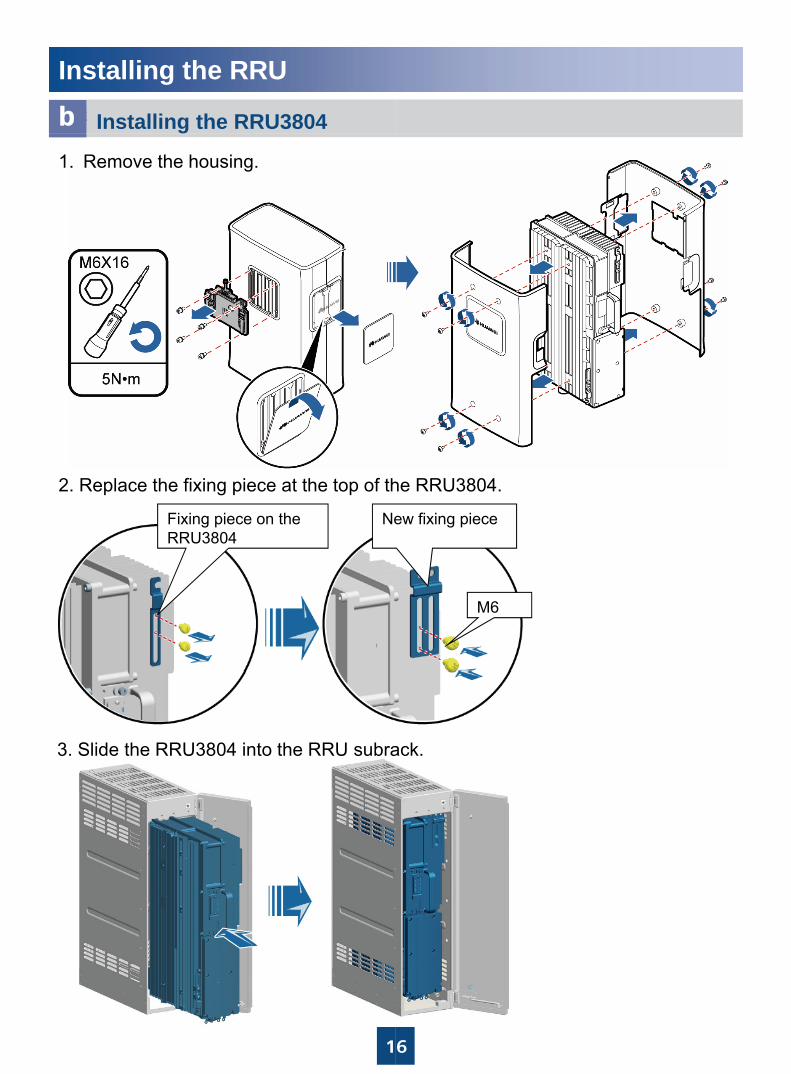
Installing the RRU• 安装RRU3804Installing the RRU3804b
1. Remove the housing.
2. Replace the fixing piece at the top of th
NeFixing piece on the RRU3804RRU3804
3. Slide the RRU3804 into the RRU subra
1
he RRU3804.
ew fixing piece
M6
ack.
6
Installing the RRU
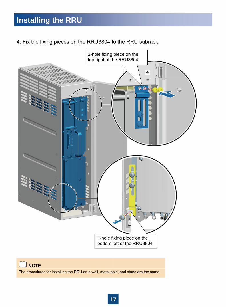
b4. Fix the fixing pieces on the RRU3804 t
2-hole fixing top right of th
1-hole fibottom l
1
The procedures for installing the RRU on a wall, metal po
o the RRU subrack.
piece on the he RRU3804
ixing piece on the left of the RRU3804
7
ole, and stand are the same.
W th ES
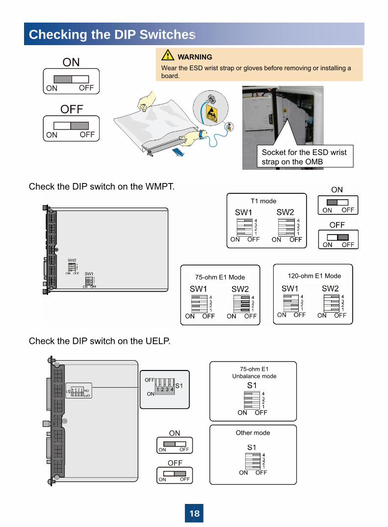
Checking the DIP Switches
Wear the ESboard.
Check the DIP switch on the WMPT.
Check the DIP switch on the UELP.
1
SD i t t l b f i i t lli
s
SD wrist strap or gloves before removing or installing a
Socket for the ESD wrist strap on the OMB
T1 mode
75-ohm E1 Mode 120-ohm E1 Mode
75-ohm E1 Unbalance mode
Other mode
8
Installing the BTS3900C Ca
a Installing the Cables through
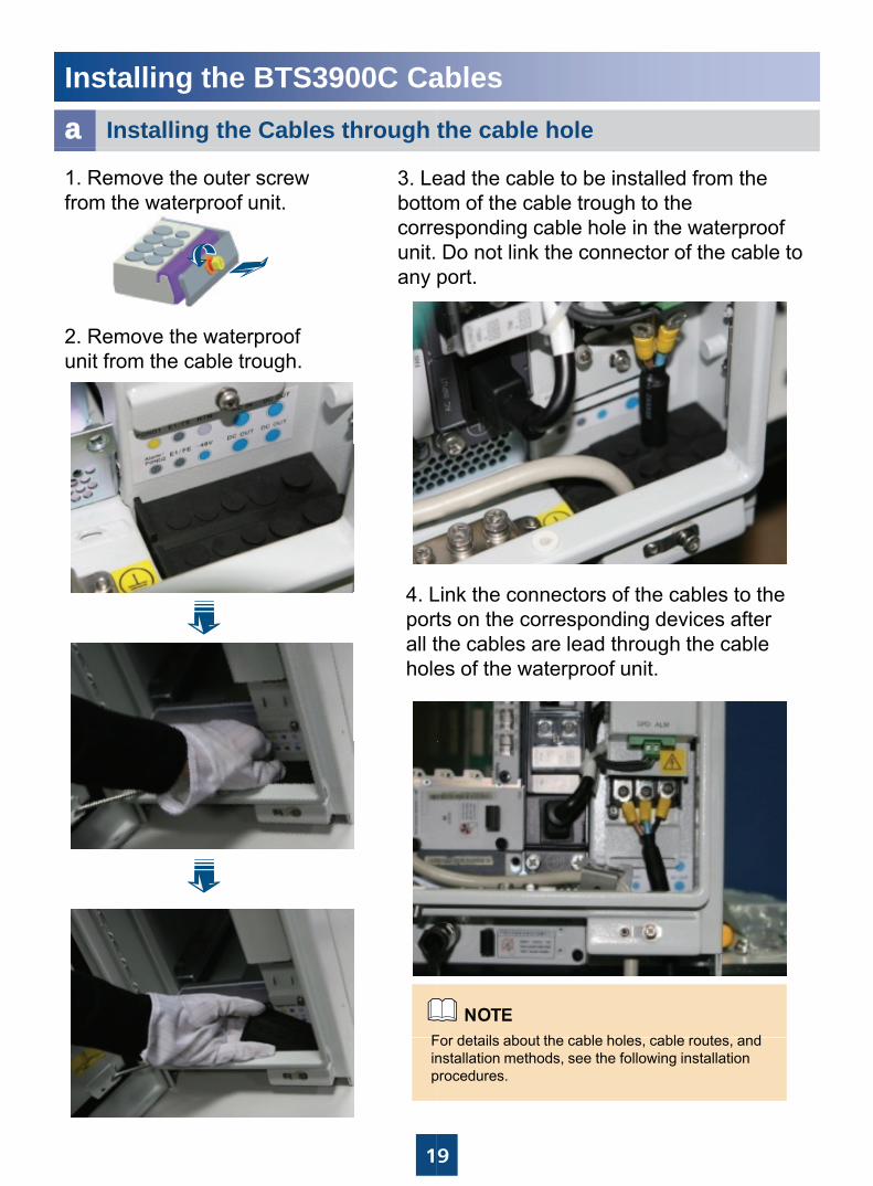
1. Remove the outer screw from the waterproof unit.
3. Lebottocorreunit. any
2. Remove the waterproof unit from the cable trough.
4 L4. Lportall thole
F
1
Finp
ablesthe cable hole
ead the cable to be installed from the om of the cable trough to the esponding cable hole in the waterproof Do not link the connector of the cable to port.
Link the connectors of the cables to theLink the connectors of the cables to the ts on the corresponding devices after the cables are lead through the cable es of the waterproof unit.
F d t il b t th bl h l bl t d
9
For details about the cable holes, cable routes, and nstallation methods, see the following installation procedures.
Installing the BTS3900C Ca
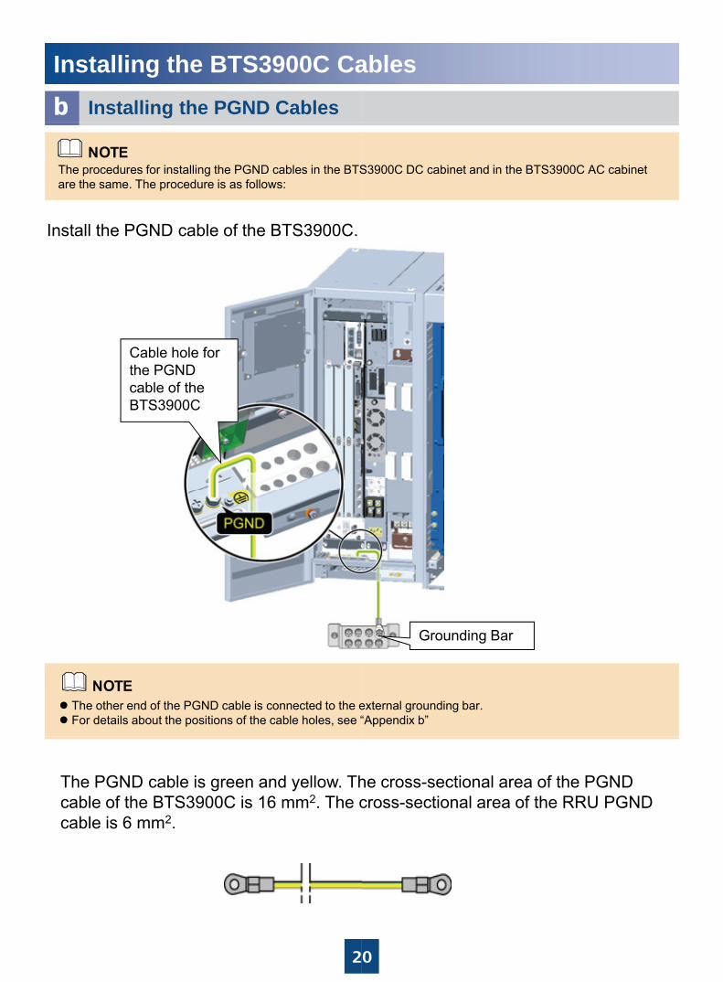
b Installing the PGND Cables
Install the PGND cable of the BTS3900C.
The procedures for installing the PGND cables in the BTSare the same. The procedure is as follows:
Cable hole for the PGNDthe PGND cable of the BTS3900C
The other end of the PGND cable is connected to the eFor details about the positions of the cable holes, see “
The PGND cable is green and yellow. Thcable of the BTS3900C is 16 mm2. The ccable is 6 mm2.
2
ables
S3900C DC cabinet and in the BTS3900C AC cabinet
external grounding bar.“Appendix b”
Grounding Bar
he cross-sectional area of the PGND cross-sectional area of the RRU PGND
0
Installing the BTS3900C Ca
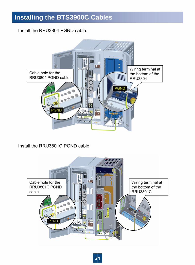
Install the RRU3804 PGND cable.
Cable hole for the RRU3804 PGND cable
Install the RRU3801C PGND cable.
Cable hole for the RRU3801C PGND cable
2
ables
Wiring terminal at the bottom of the RRU3804
Wiring terminal at the bottom of the RRU3801C
1
Installing the BTS3900C Ca
c Installing the Power Cables
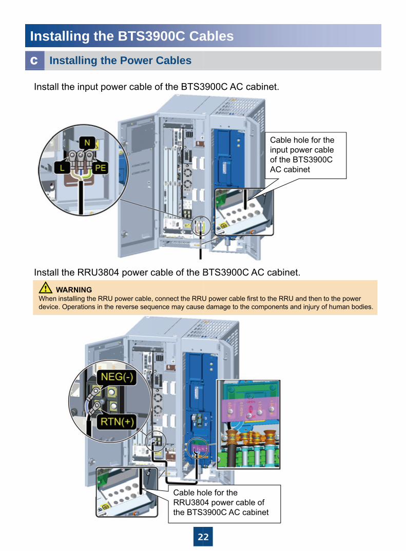
Install the input power cable of the BTS3
Install the RRU3804 power cable of the BInstall the RRU3804 power cable of the B
When installing the RRU power cable, connect the RRUdevice. Operations in the reverse sequence may cause
2
Cable hoRRU380the BTS3
ables
3900C AC cabinet.
C bl h l f thCable hole for the input power cable of the BTS3900C AC cabinet
BTS3900C AC cabinet.BTS3900C AC cabinet.
U power cable first to the RRU and then to the power e damage to the components and injury of human bodies.
2
ole for the 04 power cable of 3900C AC cabinet
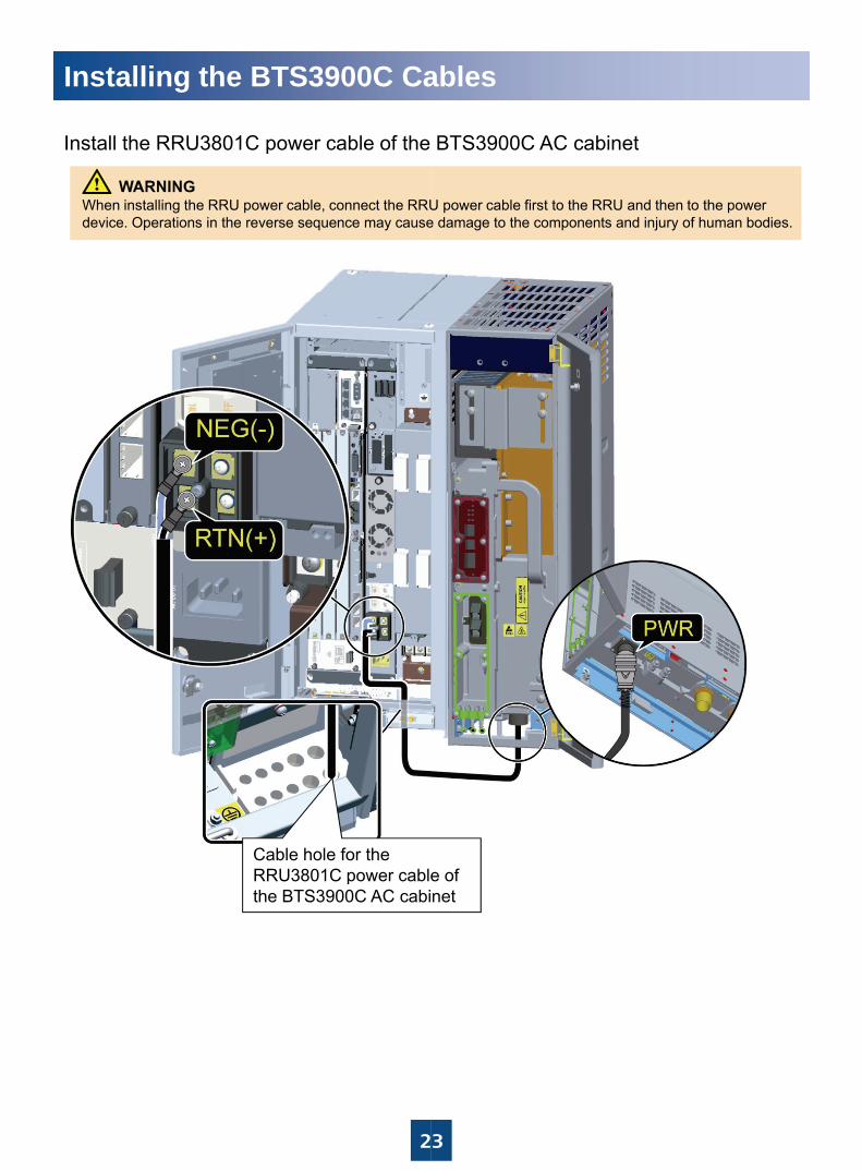
Installing the BTS3900C Ca
Install the RRU3801C power cable of theInstall the RRU3801C power cable of the
When installing the RRU power cable, connect the RRUdevice. Operations in the reverse sequence may cause
Cable hole for the RRU3801C power cableRRU3801C power cablethe BTS3900C AC cabi
2
ables
BTS3900C AC cabinetBTS3900C AC cabinet
U power cable first to the RRU and then to the power e damage to the components and injury of human bodies.
e ofe of net
3
Installing the BTS3900C Ca
cInstall the input power cable of the BTS3Install the input power cable of the BTS3
Install the RRU3804 power cable of the BInstall the RRU3804 power cable of the B
When installing the RRU power cable, connect the RRUdevice. Operations in the reverse sequence may cause
Cable hole for the RRU3804 power cable of the BTS3900C DC
bi t
2
cabinet
ables
3900C DC cabinet3900C DC cabinet.
Cable hole for the input power cable of the BTS3900C DC cabinet
BTS3900C DC cabinetBTS3900C DC cabinet.
U power cable first to the RRU and then to the power e damage to the components and injury of human bodies.
4
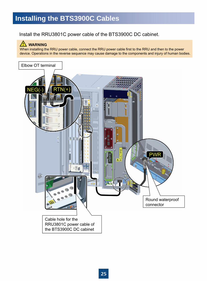
Installing the BTS3900C Ca
Install the RRU3801C power cable of thInstall the RRU3801C power cable of th
Elbow OT terminal
When installing the RRU power cable, connect the RRUdevice. Operations in the reverse sequence may cause
Cable hole for the RRU3801C power cable of the BTS3900C DC cabinet
2
ables
he BTS3900C DC cabinethe BTS3900C DC cabinet.
U power cable first to the RRU and then to the power e damage to the components and injury of human bodies.
Round waterproof connector
5
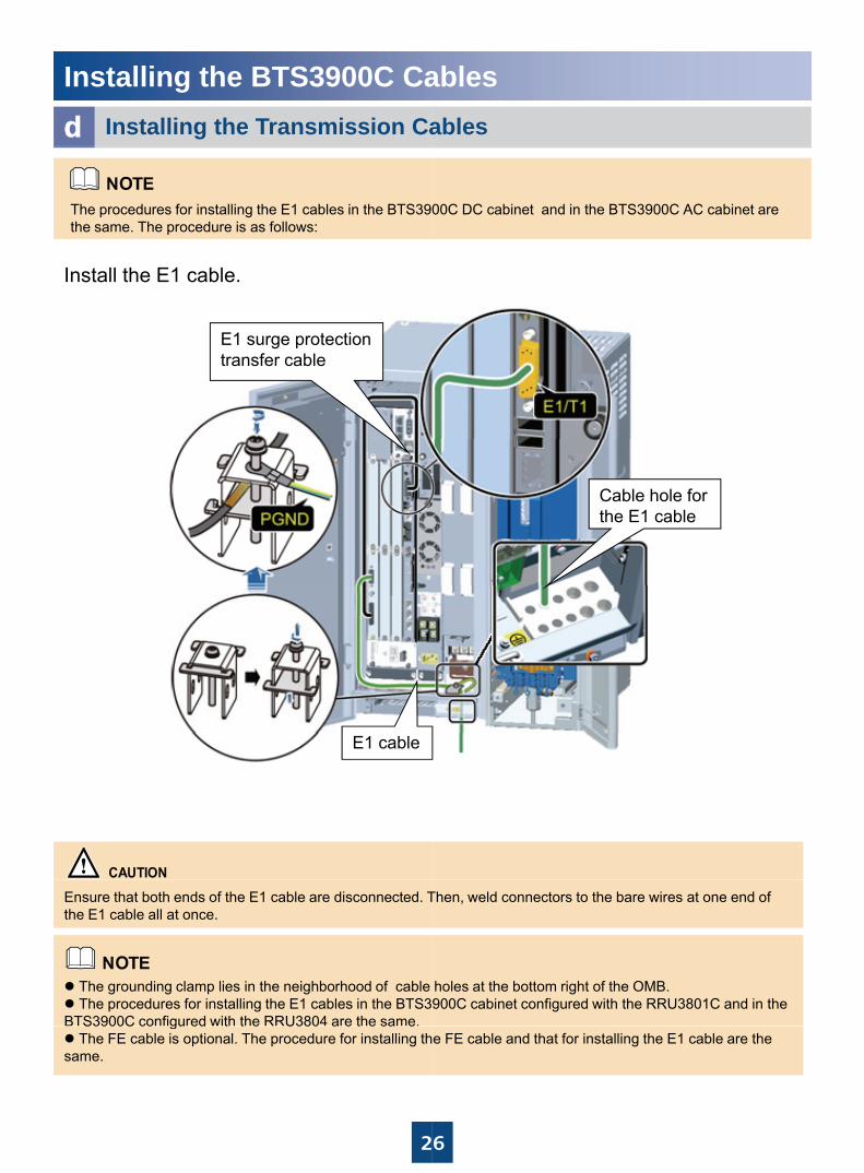
Installing the BTS3900C CaInstalling the Transmission Cad
The procedures for installing the E1 cables in the BTS390the same. The procedure is as follows:
Install the E1 cable.
E1 surge protection transfer cable
E1 cable
The grounding clamp lies in the neighborhood of cable The procedures for installing the E1 cables in the BTS3
BTS3900C configured with the RRU3804 are the same.
Ensure that both ends of the E1 cable are disconnected. Tthe E1 cable all at once.
2
S3900C co gu ed t t e U380 a e t e sa eThe FE cable is optional. The procedure for installing th
same.
ablesables
00C DC cabinet and in the BTS3900C AC cabinet are
Cable hole for the E1 cable
holes at the bottom right of the OMB.900C cabinet configured with the RRU3801C and in the
Then, weld connectors to the bare wires at one end of
6
e FE cable and that for installing the E1 cable are the
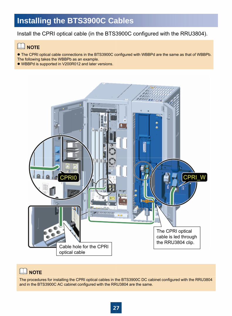
Installing the BTS3900C CaInstall the CPRI optical cable (in the BTS3
The CPRI optical cable connections in the BTS3900C cThe following takes the WBBPb as an example.
WBBPd is supported in V200R012 and later versions.
Cable hole for the CPRI optical cable
2
The procedures for installing the CPRI optical cables in tand in the BTS3900C AC cabinet configured with the RR
ables3900C configured with the RRU3804).
configured with WBBPd are the same as that of WBBPb.
The CPRI optical cable is led throughcable is led through the RRU3804 clip.
7
he BTS3900C DC cabinet configured with the RRU3804 RU3804 are the same.
Installing the BTS3900C Ca
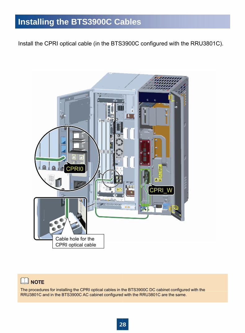
I t ll th CPRI ti l bl (i th BTS3Install the CPRI optical cable (in the BTS3
Cable hole for the CPRI optical cable
The procedures for installing the CPRI optical cables in t
2
p g pRRU3801C and in the BTS3900C AC cabinet configured
ables
3900C fi d ith th RRU3801C)3900C configured with the RRU3801C).
he BTS3900C DC cabinet configured with the
8
gd with the RRU3801C are the same.
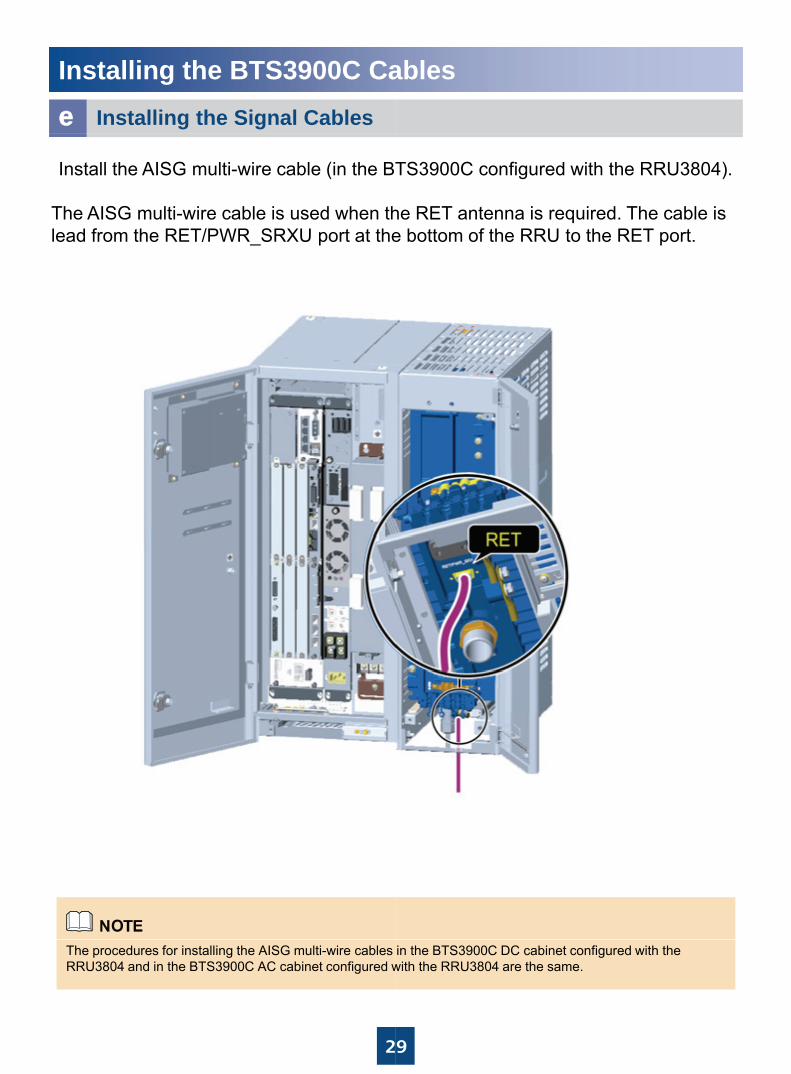
Installing the BTS3900C CaInstalling the Signal Cablese
Install the AISG multi-wire cable (in the BT
The AISG multi-wire cable is used when thlead from the RET/PWR_SRXU port at the
2
The procedures for installing the AISG multi-wire cables RRU3804 and in the BTS3900C AC cabinet configured w
ables
TS3900C configured with the RRU3804).
he RET antenna is required. The cable is e bottom of the RRU to the RET port.
9
in the BTS3900C DC cabinet configured with the with the RRU3804 are the same.
Installing the BTS3900C Ca
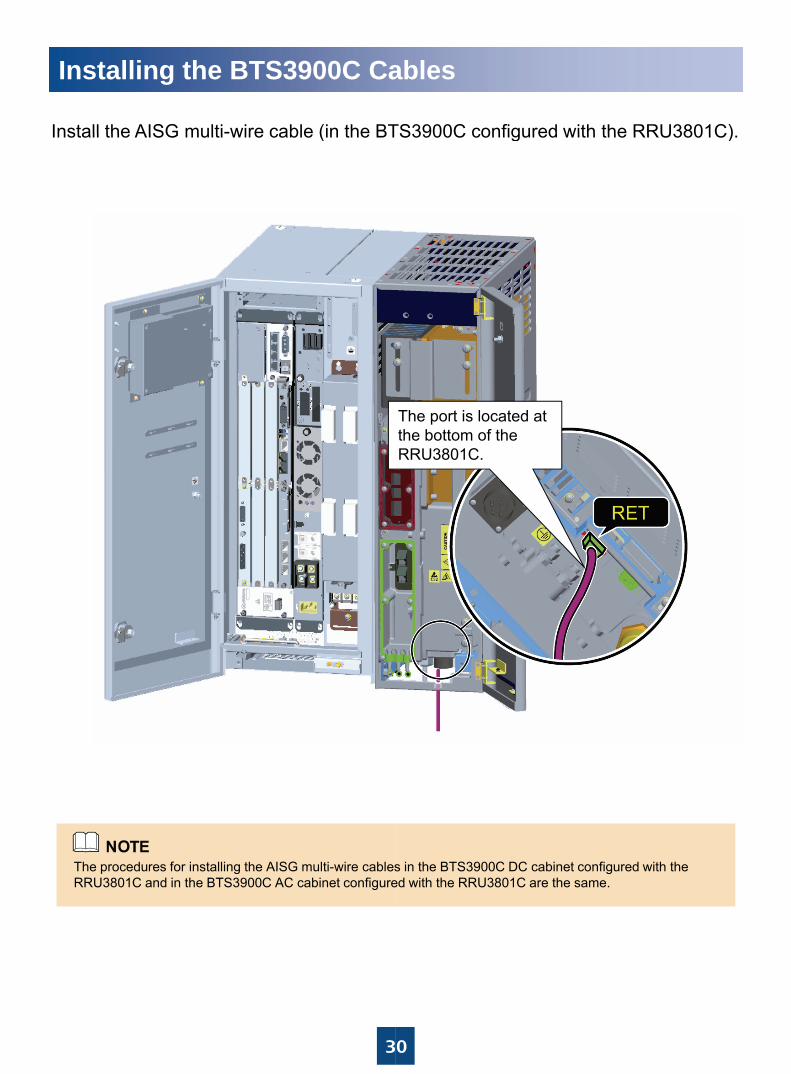
Install the AISG multi-wire cable (in the BTInstall the AISG multi wire cable (in the BT
The procedures for installing the AISG multi-wire cablesRRU3801C and in the BTS3900C AC cabinet configure
3
ables
TS3900C configured with the RRU3801C)TS3900C configured with the RRU3801C).
The port is located at the bottom of the RRU3801C.
s in the BTS3900C DC cabinet configured with the ed with the RRU3801C are the same.
0
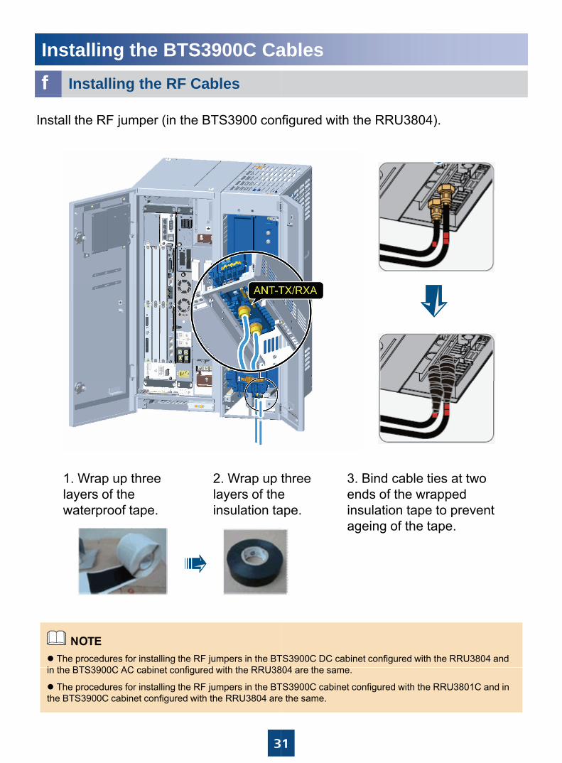
Installing the BTS3900C CaInstalling the RF Cablesf
Install the RF jumper (in the BTS3900 con
1 Wrap up three 2 Wrap up t1. Wrap up three layers of the waterproof tape.
2. Wrap up tlayers of theinsulation ta
The procedures for installing the RF jumpers in the BTi th BTS3900C AC bi t fi d ith th RRU38
3
in the BTS3900C AC cabinet configured with the RRU38
The procedures for installing the RF jumpers in the BTthe BTS3900C cabinet configured with the RRU3804 are
ables
figured with the RRU3804).
three 3 Bind cable ties at twothree e ape.
3. Bind cable ties at two ends of the wrapped insulation tape to prevent ageing of the tape.
TS3900C DC cabinet configured with the RRU3804 and 804 th
1
804 are the same.
TS3900C cabinet configured with the RRU3801C and in e the same.
Checklist for the BTS3900C
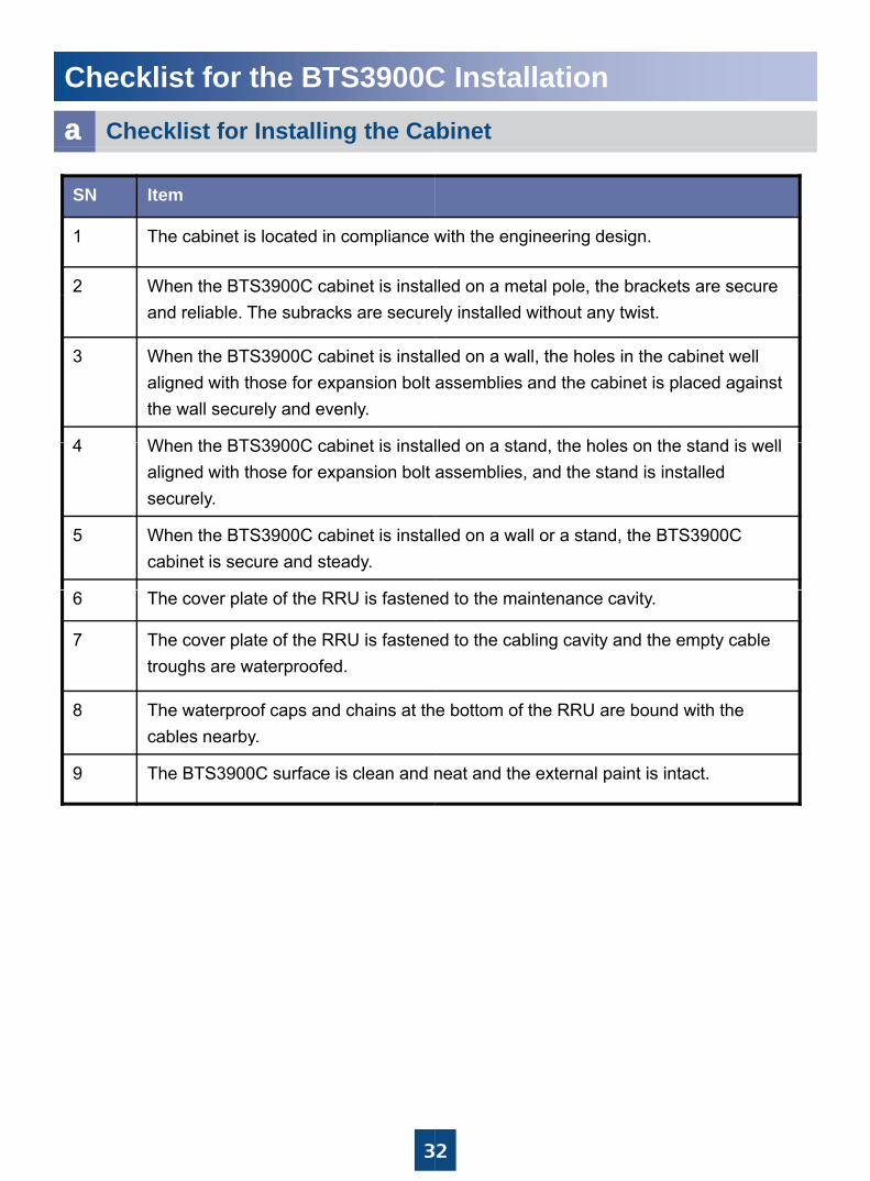
a Checklist for Installing the Ca
SN Item
1 The cabinet is located in compliance w
2 When the BTS3900C cabinet is instaland reliable. The subracks are secure
3 When the BTS3900C cabinet is instalaligned with those for expansion bolt the wall securely and evenly.
4 When the BTS3900C cabinet is instal4 When the BTS3900C cabinet is instalaligned with those for expansion bolt securely.
5 When the BTS3900C cabinet is instalcabinet is secure and steady.
6 The cover plate of the RRU is fastene
7 The cover plate of the RRU is fastenetroughs are waterproofed.
8 The waterproof caps and chains at thcables nearbycables nearby.
9 The BTS3900C surface is clean and n
3
C Installation
binet
with the engineering design.
lled on a metal pole, the brackets are secure pely installed without any twist.
lled on a wall, the holes in the cabinet well assemblies and the cabinet is placed against
lled on a stand the holes on the stand is elllled on a stand, the holes on the stand is well assemblies, and the stand is installed
lled on a wall or a stand, the BTS3900C
ed to the maintenance cavity.
ed to the cabling cavity and the empty cable
e bottom of the RRU are bound with the
neat and the external paint is intact.
2
Checklist for the BTS3900C
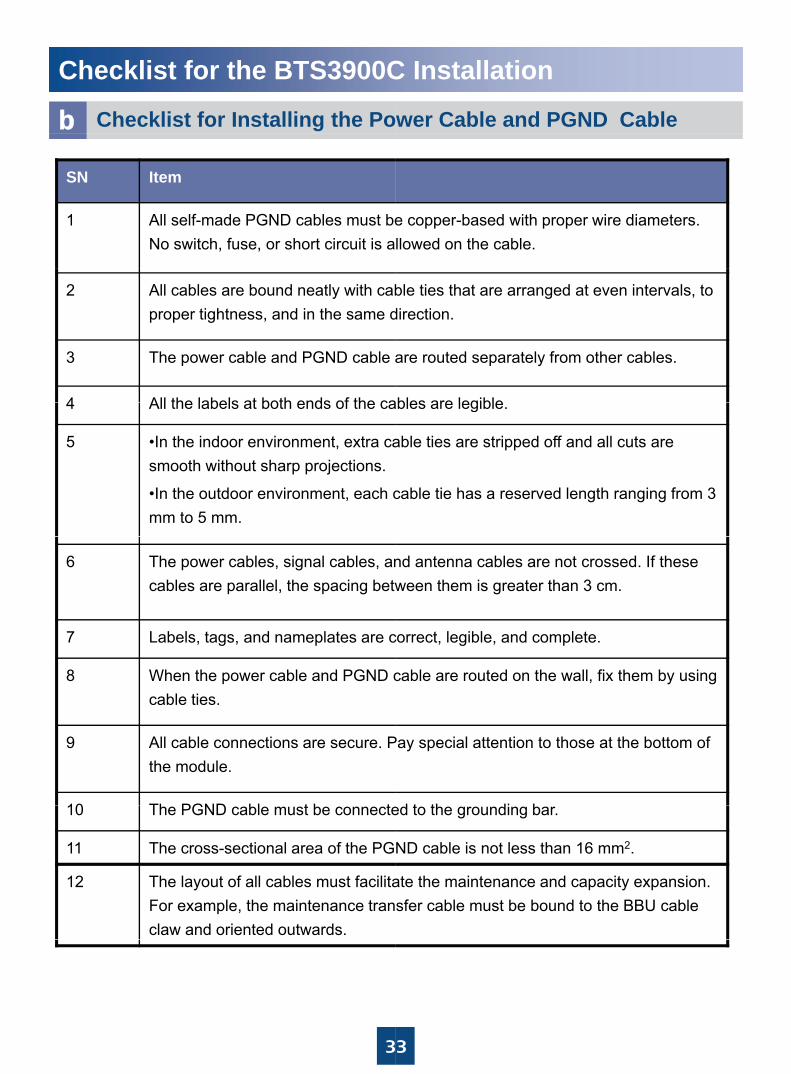
b Checklist for Installing the Po
SN Item
1 All self-made PGND cables must beNo switch, fuse, or short circuit is a
2 All cables are bound neatly with cabproper tightness, and in the same d
3 The power cable and PGND cable a
4 All the labels at both ends of the ca4 All the labels at both ends of the ca
5 •In the indoor environment, extra casmooth without sharp projections.
•In the outdoor environment, each cmm to 5 mm.
6 The power cables, signal cables, ancables are parallel, the spacing betw
7 Labels, tags, and nameplates are c
8 Wh th bl d PGND8 When the power cable and PGND ccable ties.
9 All cable connections are secure. Pthe module.
10 Th PGND bl t b t10 The PGND cable must be connecte
11 The cross-sectional area of the PG
12 The layout of all cables must facilitaFor example, the maintenance tranclaw and oriented outwards.
3
C Installation
wer Cable and PGND Cable
e copper-based with proper wire diameters. llowed on the cable.
ble ties that are arranged at even intervals, to direction.
are routed separately from other cables.
ables are legibleables are legible.
able ties are stripped off and all cuts are
cable tie has a reserved length ranging from 3
nd antenna cables are not crossed. If these ween them is greater than 3 cm.
correct, legible, and complete.
bl t d th ll fi th b icable are routed on the wall, fix them by using
Pay special attention to those at the bottom of
d t th di bed to the grounding bar.
ND cable is not less than 16 mm2.
ate the maintenance and capacity expansion. sfer cable must be bound to the BBU cable
3
Checklist for the BTS3900C
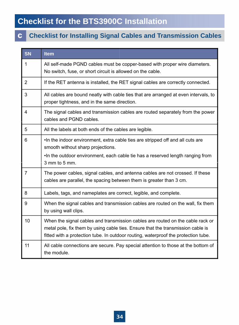
c Checklist for Installing Signal
SN Item
1 All self-made PGND cables must beNo switch, fuse, or short circuit is al
2 If th RET t i i t ll d th R2 If the RET antenna is installed, the R
3 All cables are bound neatly with cabproper tightness, and in the same d
4 The signal cables and transmission cables and PGND cables.
5 All the labels at both ends of the cab
6 •In the indoor environment, extra casmooth without sharp projections.
•In the outdoor environment, each c3 mm to 5 mm3 mm to 5 mm.
7 The power cables, signal cables, ancables are parallel, the spacing betw
8 Labels, tags, and nameplates are co
9 When the signal cables and transmi9 When the signal cables and transmiby using wall clips.
10 When the signal cables and transmimetal pole, fix them by using cable tfitted with a protection tube. In outdo
11 All bl ti P11 All cable connections are secure. Pathe module.
3
C InstallationCables and Transmission Cables
e copper-based with proper wire diameters. lowed on the cable.
RET i l bl tl t dRET signal cables are correctly connected.
ble ties that are arranged at even intervals, to irection.
cables are routed separately from the power
bles are legible.
able ties are stripped off and all cuts are
cable tie has a reserved length ranging from
nd antenna cables are not crossed. If these ween them is greater than 3 cm.
orrect, legible, and complete.
ission cables are routed on the wall fix themission cables are routed on the wall, fix them
ission cables are routed on the cable rack or ties. Ensure that the transmission cable is oor routing, waterproof the protection tube.
i l tt ti t th t th b tt fay special attention to those at the bottom of
4
Appendix
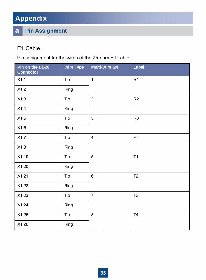
aa Pin Assignment
Pin on the DB26 Wire Type Multi-W
E1 CablePin assignment for the wires of the 75-oh
Connector
X1.1 Tip 1
X1.2 Ring
X1.3 Tip 2
X1.4 Ring
X1.5 Tip 3
X1.6 Ring
X1.7 Tip 4
X1.8 Ring
X1.19 Tip 5
X1.20 Ring
X1 21 Ti 6X1.21 Tip 6
X1.22 Ring
X1.23 Tip 7
X1.24 Ring
X1.25 Tip 8
X1.26 Ring
3
Wire SN Label
hm E1 cable
R1
R2
R3
R4
T1
T2T2
T3
T4
5

Appendix
Pin assignment for the wires of the 120-o
Pin on the DB26 Connector
Wire Color Wire
X.1 Blue Twis
X.2 White
X.3 Orange Twis
X.4 White
X 5 Green TwisX.5 Green Twis
X.6 White
X.7 Brown Twis
X.8 White
X.19 Green Twis
X.20 White
X.21 Blue Twis
X.22 Red
X.23 Orange Twis
X.24 Red
X.25 Green Twis
X 26 RedX.26 Red
3
ohm E1 surge protection transfer cable
e Type Label
sted pair R1
sted pair R2
sted pair R3sted pair R3
sted pair R4
sted pair T1
sted pair T2
sted pair T3
sted pair T4
6
Appendix
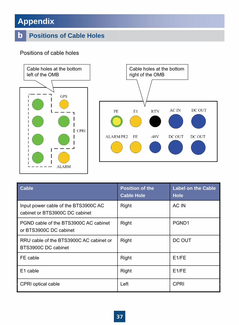
ab Positions of Cable Holes
Positions of cable holes
Cable holes at the bottom left of the OMB
Cable
Input power cable of the BTS3900C AC cabinet or BTS3900C DC cabinet
PGND cable of the BTS3900C AC cabinet or BTS3900C DC cabinet
RRU cable of the BTS3900C AC cabinet or BTS3900C DC cabinet
FE cable
E1 cable
CPRI optical cable
3
CPRI optical cable
Cable holes at the bottom right of the OMB
Position of the Cable Hole
Label on the Cable Hole
Right AC IN
Right PGND1
Right DC OUT
Right E1/FE
Right E1/FE
Left CPRI
7
Left CPRI
Change History
This describes changes in the BTS3900This describes changes in the BTS3900
06(2013-03-08)This is the sixth official release.Compared with issue 05, this issue addepower cable.
05(2012-02-10)This is the fifth official release.Compared with issue 04, this issue updaRRU3804 housing.
04(2012-01-10)04(2012 01 10)This is the fourth official release.Compared with issue 03, this issue updadocuments and product versions.
03(2011-11-20)This is the third official releaseThis is the third official release.Compared with issue 02, added the checcable.
02(2011-04-10)This is the second official release.Compared with issue 01 this issue updaCompared with issue 01, this issue upda
01(2011-03-30)This is the first official release.Compared with Draft A, this issue added“Installing the BTS3900C Cables ”.
Draft A(2011-01-30)This is the draft.
H
3
C WCDMA Installation GuideC WCDMA Installation Guide.
ed the attention for installing the RRU
ated the procedure for removing the
ated the version mapping between
cklist about the maintenance transfer
ated the front cover and back coverated the front cover and back cover.
d some pictures in the chapter of
UAWEI TECHNOLOGIES CO., LTD.Huawei Industrial Base Bantian Longgang
Sh h 518129
8
Shenzhen 518129People’s Republic of China
www.huawei.com