Embed Size (px)
Citation preview

8/20/2019 BTEC Unit 82 HND Aerospace
http://slidepdf.com/reader/full/btec-unit-82-hnd-aerospace 1/14
Unit 82 Aircraft System Principles and Applications Craig Jones
Block Diagram Reduction (LO1.3)
Question 1.
1
+++G!s"G2!s"G1!s"
# ++
$2!s"
$1!s" G%!s"
G + G%G1G2++
# +
$2
$1
G + G%G1G2
1
−G1G2 H 1
+
#
$2

8/20/2019 BTEC Unit 82 HND Aerospace
http://slidepdf.com/reader/full/btec-unit-82-hnd-aerospace 2/14
Unit 82 Aircraft System Principles and Applications Craig Jones
θ1!S" θ2!S"
&'( θ2!S" ( G1G2(G3+G 4 )
1−G1G 2 H 1+G1G 2 (G 3+G4 ) H 2 .θ1!S"
Question 2.
❑d1(s )
❑0(s)
❑1 (s)
❑d2(s )
Utilising superposition)
2
G 1G2(G 3+G 4)1−G1G2 H 1
+
$2
G1G2(G3+G 4 )
1−G1G 2 H 1+G1G 2 (G 3+G4 )
#
++
+ G2!s"G1!s"
$1!s" $2!s"

8/20/2019 BTEC Unit 82 HND Aerospace
http://slidepdf.com/reader/full/btec-unit-82-hnd-aerospace 3/14
Unit 82 Aircraft System Principles and Applications Craig Jones
&*e loc, diagram ao-e *as inputs and 1 output. &o sol-e t*e diagram eac*
input /it* t*e e0ception of one /ill eual ero t*us allo/ing t*e ne/ circuit to e
reduced.
3nputs ❑d1 and ❑d2 ( 4
❑0
❑1
= G1G 2
1+G 1G 2 H 1 H 2
3nputs ❑1 and ❑d2 ( 4
❑0
❑d1
= G2
1−G1G2 H 1 H 2
3nputs ❑1 and ❑d1 ( 4
❑0
❑d2
= H 1G1G2
1+G1G2 H 1 H 2
5o/ using 6aplaces linear relations*ip eac* output can e summed toget*er getting
t*e total transfer function ! ❑1 (s) "
❑1 (s)=
G1G2❑0(s)
1+G1G2 H 1 H 2+
G 2❑d1(s)
1−G1G2 H 1 H 2+ H 1G1G2❑d 2(s)
1+G1G2 H 1 H 2
❑1 (s)=
G 1G 2❑0(s)G 2❑
d1(s)
1+G1G2 H 1 H 2+ H 1G 1G2❑
d2 (s)
1−G1G 2 H 1 H 2
Question 3. (LO 1.4)
7ifferent control met*ods are appropriate to different types of system. &*e o-erall
control strategy can e ased on analogue or digital tec*niues !or a mi0ture".
3nstrument systems in modern aircraft display a -ast array of information. All t*is
information comes from -arious sources and sensors. Sensors deli-er an array of
information in many formats some of /*ic* may need con-erting.
3.1 Digital to analogue converters:
7igital control in-ol-es t*e use of signals and uantities t*at -ary in discrete steps.
alues t*at fall et/een t/o ad9acent steps must ta,e one or ot*er -alue as
intermediate -alues are disallo/ed.
A asic digital to analogue !7AC" *as a numer of digital inputs often 8 14 12 or 1:
and a single analogue output.

8/20/2019 BTEC Unit 82 HND Aerospace
http://slidepdf.com/reader/full/btec-unit-82-hnd-aerospace 4/14
Unit 82 Aircraft System Principles and Applications Craig Jones
3.2 nalogue to Digital !onverters:
Analogue control in-ol-es t*e use of signals and uantities t*at are continuously
-ariale. ;it*in analogue control systems signals are represented y -oltages and
currents t*at can ta,e any -alue et/een t/o set limits.&*e signals reuired for t*e operation of electronically#controlled systems utilised in
most aircraft today egin as an analogue input in t*e first instance. Analogue inputs
y t*eir nature are continuously c*anging in -alue. Some e0amples of analogue
inputs are engine operating pressure and temperatures fuel uantity *eading
c*ange and in an automated flying control system !A'CS" t*ey relate to altitude
airspeed and attitude c*anges of t*e aircraft.
A asic analogue to digital con-erter !A7C" *as a single input and a numer of
digital outputs. arious A7C<s are a-ailale /it* uses in different applications
including multi#c*annel A7C<s /it* up to 1: analogue inputs.
&*e accuracy of suc* de-ices is uite *ig* ut for modern aircraft systems /*ic*
reuire a greater capacity for data processing and a faster means of transferring any
corresponding output signals t*ey are limited in t*eir application. &*ese
reuirements are essential for t*e operation of t*e modern aircraft. 3n order for data
signal reuirements to e met t*e signals corresponding to input data are con-erted
from t*eir c*anging or analogue format into a discrete digital coded format.
4. "nvestigate and anal#se an energ# $lo% control s#stem as $ollo%s:
%
8/20/2019 BTEC Unit 82 HND Aerospace
http://slidepdf.com/reader/full/btec-unit-82-hnd-aerospace 5/14
Unit 82 Aircraft System Principles and Applications Craig Jones
4.1 7ra/ and appropriately lael t*e general loc, diagram of an open#loop transfer
system gi-ing t/o suitale aircraft e0amples.
'igure 1. =pen 6oop System
3n figure 1 t*e open loop system s*o/n *as no position feedac,. &*is type of
system is totally unsuitale as a precision control system. &*is type of arrangement
could *o/e-er e suitale for ot*er systems suc* as cain pressure control. &*e
motor may e part of an open#loop system for operating a utterfly -al-e t*at may
regulate outflo/ from t*e aircraft cain maintaining pressure at different altitudes.
Anot*er e0ample of an open loop system can e found /it*in an aircraft>s cooling
system.
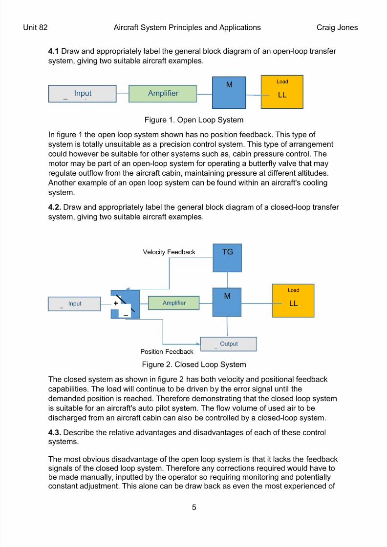
4.2. 7ra/ and appropriately lael t*e general loc, diagram of a closed#loop transfer
system gi-ing t/o suitale aircraft e0amples.
'igure 2. Closed 6oop System
&*e closed system as s*o/n in figure 2 *as ot* -elocity and positional feedac,capailities. &*e load /ill continue to e dri-en y t*e error signal until t*e
demanded position is reac*ed. &*erefore demonstrating t*at t*e closed loop system
is suitale for an aircraft>s auto pilot system. &*e flo/ -olume of used air to e
disc*arged from an aircraft cain can also e controlled y a closed#loop system.
4.3. 7escrie t*e relati-e ad-antages and disad-antages of eac* of t*ese controlsystems.
&*e most o-ious disad-antage of t*e open loop system is t*at it lac,s t*e feedac,signals of t*e closed loop system. &*erefore any corrections reuired /ould *a-e to
e made manually inputted y t*e operator so reuiring monitoring and potentiallyconstant ad9ustment. &*is alone can e dra/ ac, as e-en t*e most e0perienced of
?
6oad
66
@
Amplifier 3nput
elocity 'eedac, &G
Amplifier 3nput
6oad
66&@
'
=utput
Position 'eedac,

8/20/2019 BTEC Unit 82 HND Aerospace
http://slidepdf.com/reader/full/btec-unit-82-hnd-aerospace 6/14
Unit 82 Aircraft System Principles and Applications Craig Jones
operators can ma,e mista,es and /it*out feedac, t*ere is no guarantee t*at t*econtrol inputs applied to t*e process /ill actually *a-e t*e desired effect. &*eprincipal dra/ac, of an open#loop control is loss of accuracy. Alt*oug* t*e lac, of afeedac, controller and feedac, signal can *a-e its ad-antages if used on asuitale system. &*ere are many applications /*ere e0perienced operators can
ma,e manual corrections faster t*an a feedac, controller can. Using ,no/ledge oft*e process> past e*a-iours operators can manipulate process inputs no/ toac*ie-e t*e desired output -alues later. A feedac, controller on t*e ot*er *andmust /ait until t*e effects of its latest efforts are measurale efore it decides on t*ene0t appropriate control action. Predictale processes /it* long time constants ore0cessi-e dead time are particularly suited for open#loop manual control.
&*e iggestprinciple ad-antage of t*e closed loop system is t*e feedac,controllersignal. &*e feedac, can for e0ample ,eep an aircraft on a steady *eading/*en used /it*in an autopilot system. B-ery feedac, controller *as a differentstrategy for accomplis*ing its particular target ut all use some -ariation on t*e
closed#loop control algorit*m. &*is algorit*m is measure a process -ariale decideif its -alue is acceptale apply a correcti-e effort as necessary and repeat t*e /*oleoperation infinitely. 3f an error occurs t*en)
Brror ( reference -alue measured -alue signal.
$o/e-er feedac, controllers must operate in t*e open#loop mode on occasion
s*ould a sensor fail to generate t*e feedac, signal or an operator may ta,e o-er
t*e feedac, operation to manipulate t*e controller>s output manually. Prolems as
mentioned ao-e may t*en occur /it* t*ese manual inputs.
4.4. C*oose one of your e0amples of a closed#loop control system and gi-e an in#
dept* analysis as to t*e function of)
%.%.1. &*e indi-idual elements.
&*e e0ample 3 s*all concentrate on is t*e closed loop system of t*e Autopilot
system /it* t*e load as t*e tail rudder. !ref figure 2 closed loop system".
"nut transducer: 3nput &ransducers con-ert a uantity to an electrical signal
!-oltage" or to resistance !/*ic* can e con-erted to -oltage". 3nput transducers are
also called sensors.
rror detector: !auto pilot computer" S*o/n in t*e system diagram as a 0 /it*in a
circle t*e error detector /or,s y comparing t*e demand and feedac, signals. &*e
t/o signals are added toget*er algeraically and t*e resultant output is used to dri-e
t*e motor. 3n practice t*e error detection is ac*ie-ed t*roug* a summing 9unction and
op#amp.
mli$ier: &*e amplifier is used to amplify t*e /ea, electrical signal it recei-es from
t*e error detector. Amplification is done y using gain /it*in t*e component. Gain is
generally calculated y t*e ratio or t*e output po/er to t*e input po/er and is
measured in deciels !dD".
:

8/20/2019 BTEC Unit 82 HND Aerospace
http://slidepdf.com/reader/full/btec-unit-82-hnd-aerospace 7/14
Unit 82 Aircraft System Principles and Applications Craig Jones
*ac+o ,enerator (*,)) &*e &G is an electromec*anical de-ice /*ic* produces a
signal proportional to t*e speed off rotation. &*e &G connects to t*e motor -ia t*e
s*aft and its role /it*in t*e system is to pre-ent a prolem called E*untingF. &*is is
est e0plained using an e0ample t*e load mo-es to its demanded position *o/e-er
it cannot stop e0actly at t*e correct position due to inertia. &*e load t*erefore
o-ers*oots causing an error signal so t*e motor sends t*e load ac, t*e ot*er /ay it
again o-ers*oots and t*e load /ill fluctuate around t*e demand position.
Outut transducer: &*is de-ice is connected to t*e systems motor -ia a s*aft and
pro-ides t*e error detector /it* position feedac, signals.
-otor: &*e @otor in t*is arrangement is connected to a ser-omec*anism /*ic* is in
turn connected to t*e load. &*e @otor pro-ides t*e reuired force to mo-e t*e
ser-omec*anism /*ic* it turn mo-es t*e load.
ervomec+anism: Used typically to mo-e control surfaces radar antennae are
used e0tensi-ely in autopilot and auto#stailiser systems. 3n s*ort Ser-os are used tomo-e a mec*anical load to a desired position /it* a *ig* degree of accuracy and
using a small control signal. Ser-os can e implemented in -arious forms including)
Blectrical
$ydraulic
Pneumatic
Blectro#*ydraulic
%.%.2. &*e system as a /*ole.
'or t*is let<s consider t*e e0ample of a pilot /*o *as acti-ated a single#a0isautopilot)
&*e pilot sets a control mode to maintain t*e /ings in a le-el position.
1. $o/e-er e-en in t*e smoot*est air a /ing /ill e-entually dip.
2. Position sensors on t*e /ing detect t*is deflection and send a signal to t*eautopilot computer.
. &*e autopilot computer processes t*e input data and determines t*at t*e /ingsare no longer le-el.
%. &*e autopilot computer sends a signal to t*e ser-os t*at control t*e aircraft>sailerons. &*e signal is a -ery specific command telling t*e ser-o to ma,e a precisead9ustment.
?. Bac* ser-o *as a small electric motor fitted /it* a lip clutc* t*at t*roug* a ridlecale grips t*e aileron cale. ;*en t*e cale mo-es t*e control surfaces mo-eaccordingly.
:. As t*e ailerons are ad9usted ased on t*e input data t*e /ings mo-e ac, to/ardle-el.
H. &*e autopilot computer remo-es t*e command /*en t*e position sensor on t*e
/ing detects t*at t*e /ings are once again le-el.
8. &*e ser-os cease to apply pressure on t*e aileron cales.
H

8/20/2019 BTEC Unit 82 HND Aerospace
http://slidepdf.com/reader/full/btec-unit-82-hnd-aerospace 8/14
Unit 82 Aircraft System Principles and Applications Craig Jones
&*is loop s*o/n ao-e in t*e loc, diagram /or,s continuously many times asecond muc* more uic,ly and smoot*ly t*an a *uman pilot could. &/o# and t*ree#a0is autopilots oey t*e same principles employing multiple processors t*at controlmultiple surfaces. Some aircraft *a-e auto t*rust computers to also control enginet*rust.
Autopilot and auto t*rust systems can /or, toget*er to perform -ery comple0manoeu-res and also alle-iating t*e fatigue placed on pilots.
/. 0lain t+e oeration o$ an aircra$t remote osition control s#stem.
utot+rottle #stem.
An autot*rottle system is of t*e computer controlled electro#mec*anical type
designed to control t*e t*rust of an aircraft<s engines /it*in specific engine design
parameters t*e t*rottle position of eac* engine is controlled to maintain a specific
-alue of t*rust in terms of eit*er rotational speed !51" or engine pressure ratio
!BPI" or a target speed. &ypically t*ese systems can operate o-er t*e full flig*tregime from ta,e#off to s*ut do/n. 3t is designed to /or, primarily in con9unction /it*
t*e A'CS to *elp maintain an aircrafts speed and -ertical pat* and also a flig*t
management computer system !'@CS". ;*en an A'CS mode is controlling
airspeed t*e autot*rottle system controls engine t*rust to a specific -alue. ;*en an
A'CS mode is maintaining a -ertical pat* t*e autot*rottle system maintains
airspeed troug* t*rust control.
Oerating -odes.
&*e autot*rottle system operation is primarily controlled t*roug* t*e mode control
panel !@CP" of t*e A'CS and t*e indications of t*e reuisite selections necessaryfor arming t*e system and operating it in t*e rele-ant modes are presented on t*e
@CP and on ot*er annunciators. &*ere are asically t/o modes ta,e#off and speed
control mode.
*akeo$$ -ode.
As t*e name suggests t*is mode is initiated prior to ta,e off y engaging t*e '@CS
t*e computer /*ic* pro-ides t*e engine rotational speed !51" limits for eac* flig*t
profile and also an 51 target speed. =n acti-ation of t*is system engagement is
made /it* ser-o#actuators /*ic* control t*e t*rottle position. &*e Ser-o#actuators
t*en ad-ance t*e t*rust le-ers at a particular rate to t*e predicted position to otain51 -alues efore a ta,e#off. &*e ad-ance rate of t*rottles is 1?Ks and t*e 51 -alues
are otained efore :4,nots. 3f t*e speed is e0ceeded an independent speed
detector circuit interrupts t*e operation. &*is causes t*e system to enter a *old state
and is indicated to t*e pilot.
&*e speed detector circuit is also interloc,ed /it* micros/itc*es on t*e main landing
gear s*oc, struts so t*at in t*e e-ent of it failing to perform t*e *old function t*e
micros/itc*es /ill do so as a result of t*e aircraft lifting off. &*e micros/itc*es
circuits also acti-ate timers /*ic* /ill reinstate t*e control system after a specified lift
time. 7uring t*is time t*e aircraft /ill *a-e climed to a specific radio altitude. 3n t*ee-ent of an engine failure an additional interloc, circuit /ill e acti-ated. &*is is
8
8/20/2019 BTEC Unit 82 HND Aerospace
http://slidepdf.com/reader/full/btec-unit-82-hnd-aerospace 9/14
Unit 82 Aircraft System Principles and Applications Craig Jones
controlled y altitude. 'or e0ample if %44ft is not ac*ie-ed in t*e specified time t*en
it /ill not allo/ t*e t*rottle ser-o#actuator to ta,e ac, control until t*e reuired
altitude is otained. At t*is stage t*e systems are armed to control 51 speeds during
t*e remainder of t*e clim.
eed !ontrol -ode
&*is mode is selected -ia t*e @CP of t*e A'CS. =r it can e automatically selected
y t*e A'CS /*en not in speed mode. 3f -ertical na-igation ! 5A" is in operation
t*en t*e speed target is pro-ided y t*e flig*t management computer and is referred
to as '@C SP7. &*e autot*rottle system is s/itc*ed to t*is mode automatically
/*en a predetermined altitude is reac*ed under 5A. Airspeed@ac* feedac,
signals are pro-ided y t*e A7C. &*e autot*rottle system limits t*e airspeed to ma0
and min safe -alues independent of t*e target airspeed -alues and it also limits t*e
angle of attac, or alp*a angle. @inimum airspeed and ma0imum alp*a angle are
computed from signals produced y t*e flap position and t*e alp*a angle sensors.
;*en t*e aircraft egins to descend under 5A control t*e autot*rottle system
retards t*e t*rust le-ers to idle and t*is is displayed to t*e pilot !IB&AI7". &*e
retard rate is normally 2Ks t*is may *o/e-er e stopped y interrupting t*e
mo-ement of t*e t*rust le-ers or allo/ing t*em to contact /it* t*e idle stops. ;*en
t*e A'CS captures t*e glide slope eam t*e 5A mode is disengaged and t*e
autot*rottle system s/itc*es to @CP SP7 mode.
7uring t*e landing flare manoeu-re t*e retard rate of t*rust reduction is ad9usted so
t*at t*rottle angle is reduced to idle in :s. Ietard normally occurs at 2Hft of radio
altitude. 3f it is not initiated y radio altitude it can also occur 1.?s after an automatic
flare. =nce t*e aircraft *as landed and t*e undercarriage s*oc, strut micros/itc*es
are made t*e t*rust le-ers are mo-ed aft at 8Ks to remo-e any residual
displacement ao-e t*e idle position. &*e autot*rottle system is automatically
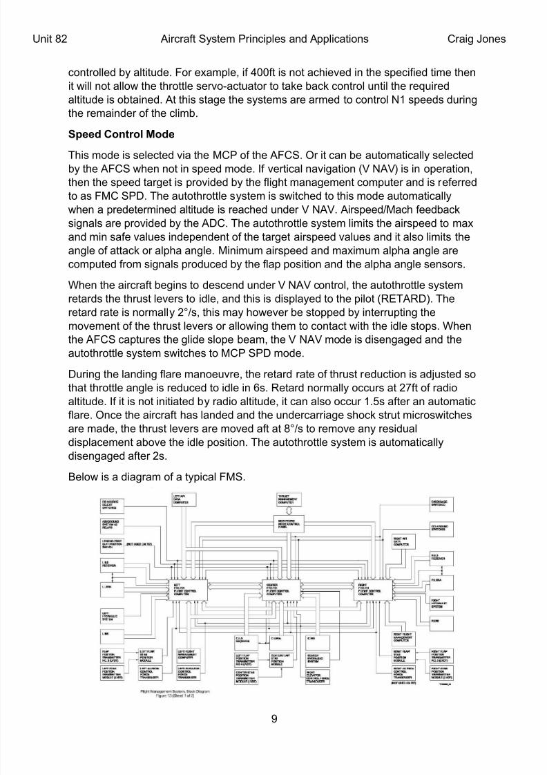
disengaged after 2s.
Delo/ is a diagram of a typical '@S.
L

8/20/2019 BTEC Unit 82 HND Aerospace
http://slidepdf.com/reader/full/btec-unit-82-hnd-aerospace 10/14
Unit 82 Aircraft System Principles and Applications Craig Jones
. Descrie t#ical causes o$ control overs+oot and +unting in aircra$t s#stem
oeration.
&*e staility of a control system is determined to a large e0tent y its response to a
suddenly applied signal or transient. 3f suc* a signal causes t*e system to
o-ercorrect itself a p*enomenon called *unting may occur in /*ic* t*e system firsto-ercorrects itself in one direction and t*en o-ercorrects itself in t*e opposite
direction. 3n an ideal /orld responses from control systems /ould respond and stop
in an ideal response time. Generally t*oug* ecause of e0ternal factors acting on
aircraft t*is rarely *appens. Also ecause of systems /or,ing on a feedac, loop
t*en t*ey reuire a small amount of o-ers*oot for t*e input to e recognised. Dut
ecause *unting is undesirale measures are usually ta,en to correct it.
. "nvestigate various daming met+ods used in aircra$t control s#stems to
control overs+oot and +unting5 eg. !oulom and viscous $riction daming5
electrical daming and velocit# $eedack daming.
&*e most common correcti-e measure is t*e addition of damping some/*ere in t*e
system. 7amping slo/s do/n t*e system response and a-oids e0cessi-e
o-ers*oots or o-ercorrections. 7amping can e in t*e form of electrical resistance in
an electronic circuit t*e application of a ra,e in a mec*anical circuit or forcing oil
t*roug* a small orifice as in s*oc,#asorer damping.
Coulom damping asors energy /it* friction /*ic* con-erts t*at ,inetic energy
into t*ermal energy or *eat. &*e Coulom friction la/ is associated /it* t/o aspects.
Static and ,inetic frictions occur in a -irating system undergoing Coulom
damping. Static friction occurs /*en t*e t/o o9ects are stationary or undergoing no
relati-e motion. 'or static friction t*e friction force ' e0erted et/een t*e surfaces
*a-ing no relati-e motion cannot e0ceed a -alue t*at is proportional to t*e product of
t*e normal force 5 and t*e coefficient of static friction Ms.
Ninetic friction occurs /*en t*e t/o o9ects are undergoing relati-e motion and t*ey
are sliding against eac* ot*er. &*e friction force ' e0erted et/een t*e mo-ing
surfaces is eual to a -alue t*at is proportional to t*e product of t*e normal force 5
and t*e coefficient of ,inetic friction M,.
3n ot* of t*ese cases t*e frictional force al/ays opposes t*e direction of motion of
t*e o9ect. &*e normal force is perpendicular to t*e direction of motion of t*e o9ect
and eual to t*e /eig*t of t*e o9ect sliding.
14

8/20/2019 BTEC Unit 82 HND Aerospace
http://slidepdf.com/reader/full/btec-unit-82-hnd-aerospace 11/14
Unit 82 Aircraft System Principles and Applications Craig Jones
6. 7sing reresentative e0amles $rom an aircra$t automatic $lig+t control
s#stem (autoilot5 auto t+rottle5 auto land) and8or engine control unit5
investigate:
8.1. Proportional and integrati-e control
A good e0ample met*od for a deri-ati-eintegrati-e and proportionalintegrati-e
control met*od is t*e P37 controller. P #Proportional 3 # 3ntegral 7 # 7eri-ati-e.
&*ese terms descrie t*ree asic mat*ematical functions applied to t*e error signal
error ( set # sensor. &*is error represents t*e difference et/een /*ere you
/ant to go !set" and /*ere you>re actually at !sensor". &*e controller performs
t*e P37 mat*ematical functions on t*e error and applies t*eir sum to a process
!motor *eater etc.". 3>ll e0plain t*e t*ree components !proportional integral and
deri-ati-e" of a P37 controller ne0t.
9roortional
All t*ree components of t*e P37 algorit*m are dri-en y t*e difference et/een t*e
process -alue !i.e. t*e current speed" and t*e reference point !i.e. t*e target speed."
;e /ill call t*is difference error" for one particular time step)
en
'or t*at same time step /e call t*e process -alue)
yn
and t*e reference point)
rn
&*erefore)
en=rn− yn
&*e output -alue is)
un
&*e proportional component simply calculates t*e output -alue ased on t*e error
term y multiplying it y a constant term so /e get)un=k p en
'or simple situations t*is all y itself can e a -ery effecti-e control algorit*m.
&ypically t*is /or,s est /*en you ,no/ t*at /*en ot* t*e error and output -alue (
4. 'or e0ample imagine a simple /ing le-eller in an aircraft. &*e process -alue is
going to e an, angle t*e reference point is going to e ero !ero an, angle
means t*e /ings are le-el". Assume a /ell#trimmed aircraft /it* neutral staility so
t*at /*en t*e ailerons are ero t*ere is no c*ange in an,. A proportional only
control /ould set t*e aileron deflection in-ersely proportional to t*e an, angle. As
t*e an, angle gets closer to ero t*e aileron deflection gets closer to ero.
11

8/20/2019 BTEC Unit 82 HND Aerospace
http://slidepdf.com/reader/full/btec-unit-82-hnd-aerospace 12/14
Unit 82 Aircraft System Principles and Applications Craig Jones
Somet*ing as simple as t*is !a formula /it* one multiply operation" can e an
amaingly effecti-e and stale controller.
"ntegral
B-en in t*e case of a simple /ing le-eler you encounter situations /*ere t*e aircraft
isn>t perfectly trim and ero aileron deflection does not al/ays eual ero roll motion.
3n an aircraft suc* as a Cessna 1H2 t*e amount of aileron deflection needed to ,eep
t*e /ing le-el can -ary /it* speed. 3n t*ese cases a proportional only controller /ill
stailie out uic,ly ut /ill stailie to t*e /rong -alue. ;e need a /ay to dri-e t*e
error in t*e proportional only controller to ero.
Bnter t*e 3ntegral component of t*e P37 algorit*m. 3ntegral refers to t*e area under a
cur-e. 3f you *a-e a function t*e integral of t*at function produces a second function
/*ic* tells you t*e area under cur-e of t*e first function. At eac* time step /e ,no/)
en
;*ic* is t*e difference et/een t*e process -alue and t*e reference point. 3f /e
multiply t*is distance times)
d t
!&*e time step" /e get an area /*ic* appro0imates t*e error under t*e cur-e 9ust for
t*is time step. 3f /e add t*ese areas up o-er time /e get a -ery reasonale
appro0imation of t*e area under t*e cur-e. Bssentially /*at t*is does is t*at t*e
longer time passes /it* us not at our target -alue t*e larger t*e sum of t*e error
ecomes o-er time. 3f /e use t*is sum to pus* our output -alue !i.e. our accelerator
position" t*en t*e longer /e don>t uite *it our target speed t*e furt*er t*e system
pus*es t*e accelerator pedal. =-er time t*e integral component compensates for
t*e error in t*e proportional component and t*e system stailies out at t*e desired
speed
Derivative
&*e deri-ati-e of a function implies t*e rate of c*ange of t*e function output. 3f you
,no/ t*e function you can ta,e t*e deri-ati-e of t*at function to produce a second
function. 'or any point in time t*e deri-ati-e function /ill tell you t*e rate of c*ange
!or slope" of t*e first function. Conceptually t*is ma,es sense in t*e conte0t of a
controller. $o/ uic,ly /e are closing on our target -alue !i.e. t*e rate of c*ange
from eac* time step to t*e ne0t" is an important piece of information t*at can *elp us
uild a more stale system t*at more uic,ly ac*ie-es t*e target -alue. 'or an
Aircraft>s cruise control /e are measuring -elocity at eac* time step. &*e rate of
c*ange of -elocity is defined as acceleration.
8.2. analoguedigital *yrid control
$yrid Systems are systems t*at *a-e ot* analogue and digital components.
7e-ices called samplers are used to con-ert analogue signals into digital signals
and 7e-ices called re#constructors are used to con-ert digital signals into analogue
12

8/20/2019 BTEC Unit 82 HND Aerospace
http://slidepdf.com/reader/full/btec-unit-82-hnd-aerospace 13/14
Unit 82 Aircraft System Principles and Applications Craig Jones
signals. Decause of t*e use of samplers *yrid systems are freuently called
sampled#data systems.
$yrid systems are generally understood as reacti-e systems t*at intermi0 discrete
and continuous components. &*e discrete part of t*e system ma,es t*e decision for
t*e /*ole system to s/itc* to anot*er set of control rules if conditions arefa-ourale. &*e continuous part as a result /or,s according to t*e ne/ rules. As to
ma,e t*e ao-e idea more concrete let us discuss t*e case of an aircraft control
system. An autopilot system may *a-e climing descending and le-el flig*t modes
in /*ic* different control la/s are used. &*e logic decision#ma,ing unit c*ooses t*e
mode automatically !t*e pilot can o-erride t*is". &*ere are a lot more e0amples suc*
as computers manufacturing production and po/er stations /*ic* are designed to
select control and super-ise t*e e*a-iour of t*e continuous components. Also t*e
potential applications for *yrid systems are -ast as most of today>s control systems
use computers and e-en consumer electronics use soft/are to control p*ysical
processes.
A good system /*ic* demonstrates &*e integration of analogue and digital systems
is t*e automatic landing system of an aircraft. 3n order to ac*ie-e a safe landing an
aircraft *as to e controlled so t*at it /*eels ma,e contact /it* ground safely. &*is
s*ould e /it*in a pa-ed surface of t*e run/ay /it*in fairly narro/ longitudinal
limits. &*e speed of touc*#do/n s*ould e reduced on t*e approac* pre-enting
stall. 'inally t*e /ings are reuired to e le-el and t*e aircraft ya/ed to ring its
longitudinal a0is parallel to t*e run/ay.
Control of t*e aircraft is needed aout all t*ree a0es simultaneously as /ell as t*e
control of t*e airspeed t*roug* engine po/er management. &*is is /*y t*e landingp*ase of a flig*t is t*e most demanding part of flying. Added to t*is is t*e large
percentage of accidents t*at occur during t*is p*ase. Accident rate statistics figure
largely in t*e de-elopment of automated landing systems. 3n t*e UN a minimum
reliaility figure is applied at a -alue of 1 in 107 . &*is means t*at a system s*ould
not cause a fatal accident more often t*an one in ten million landings.
&*e control function during t*e approac* and landing is reuired on a *ig*ly
repetiti-e asis and alt*oug* it is controlling numerous parameters it is only reuired
for a relati-ely s*ort period of time.
8.. system response to control met*ods.
Autopilot systems control t*e attitude *eading na-igation and speed for t*e aircraft
as a /ay of alle-iating t*e /or,load of t*e pilot. &*e aility of t*e system is deri-ed
from control circuits t*at monitor t*e current status of t*e system t*e *istory of t*e
system and t*e proposed future c*anges to t*e system. &*is process follo/s a
mat*ematical algorit*m. ;e *a-e pre-iously descried t*is type of system ao-e
and as /e ,no/ t*is ,no/n as a P37 system.
1

8/20/2019 BTEC Unit 82 HND Aerospace
http://slidepdf.com/reader/full/btec-unit-82-hnd-aerospace 14/14
Unit 82 Aircraft System Principles and Applications Craig Jones
=n aircraft many systems are controlled y P37 controllers enaling autonomous
action. System t*oug* /ill respond to inputs from many factors. Computers /ill
ad9ust systems depending on feedac, it recei-es.
3n a *elicopter autorotation system it senses t*e lade droop and /ill automatically
speed up or reduce t*e speed of t*e lades as reuired. &*is can e t*e result ofmany c*anges air density /ind /eig*t and speed. &*e control system /ill sense
t*e c*anges in t*ese -ariales and ad9ust t*e rotation as reuired. 'or a pilot to do
t*is for a lengt* of time /ould pro-e tiring and cause undue fatigue.
&*at system used in t*e *elicopter is -ery similar to a con-entional fi0ed /ing
aircraft. Systems *a-e to ma,e ad9ustments for c*anges in airflo/ and turulence to
name 9ust a fe/. 3n a fast 9et aircraft fine control mo-ements /ould e continuously
reuired to maintain *eig*t etc. Oou also *a-e to ta,e in to account t*e c*anges in
CofG if dropping ordinance. &*ese sort of ad9ustments at *ig* speed /ould mean
*uge amounts of concentration causing massi-e fatigue.
&*e control systems of a modern aircraft react continuously to inputs from -arious
sources as mentioned. A deflection in a flying control must e corrected if needed y
a system. @odern systems reduce fatigue and impro-e flig*t safety.
1%