Embed Size (px)
Citation preview

Customer: British Gypsum Page Amended 22nd June 2017 BTC 20080A: Page 1 of 12
The Building Test Centre British Gypsum
East Leake
Loughborough
Leics. LE12 6NP
Tel (0115) 945 1564
Fax (0115) 945 1562 Email [email protected] Website www.btconline.co.uk
Report Number BTC 20080A An acoustic test report covering laboratory sound insulation testing to BS EN ISO 10140-2:2010 on a British Gypsum GypWall Classic partition clad with a double layer of 12.5mm Gyproc WallBoard each side. (Ultraembossed Profile).
Test date: 16th May 2017
Report issued date: 16th May 2017 (Report Amended: 22nd June 2017).
www.btconline.co.uk
Customer: British Gypsum East Leake Loughborough Leicestershire LE12 6HX
Customer: British Gypsum BTC 20080A: Page 2 of 12
The Building Test Centre British Gypsum
East Leake
Loughborough
Leics. LE12 6NP
Tel (0115) 945 1564
Fax (0115) 945 1562 Email [email protected] Website www.btconline.co.uk
TABLE OF CONTENTS
FOREWORD ....................................................................................................................... 3
REPORT AUTHORISATION ............................................................................................... 3
TEST REPORT AMENDMENTS ......................................................................................... 4
TEST CONSTRUCTION ...................................................................................................... 5
TEST MATERIALS .............................................................................................................. 7
Plasterboard .................................................................................................................... 7
Metal Components ......................................................................................................... 7
Fasteners......................................................................................................................... 7
Miscellaneous Components .......................................................................................... 7
TEST RESULTS .................................................................................................................. 8
TEST PROCEDURE ............................................................................................................ 8
LIMITATIONS ...................................................................................................................... 8
APPENDIX A - TEST DATA ................................................................................................ 9
APPENDIX B - TEST METHOD AND CONDITIONS ........................................................ 11

Customer: British Gypsum BTC 20080A: Page 3 of 12
The Building Test Centre British Gypsum
East Leake
Loughborough
Leics. LE12 6NP
Tel (0115) 945 1564
Fax (0115) 945 1562 Email [email protected] Website www.btconline.co.uk
FOREWORD The test sponsor was British Gypsum. The test specimen was installed by Tony Clark on the 16th May 2017. The Building Test Centre played no role in the design or selection of the materials comprising the test specimen.
REPORT AUTHORISATION The Building Test Centre will not discuss the content of this report without written permission from the test sponsor. The Building Test Centre retains ownership of the test report content but authorises the test sponsor to reproduce the report as necessary in its entirety only.
Report Author
Martin Lynch MIOA Scientist
Authorised by
Jack Marriott BSc(Hons) Scientist
Customer: British Gypsum Page Amended 22nd June 2017 BTC 20080A: Page 4 of 12
The Building Test Centre British Gypsum
East Leake
Loughborough
Leics. LE12 6NP
Tel (0115) 945 1564
Fax (0115) 945 1562 Email [email protected] Website www.btconline.co.uk
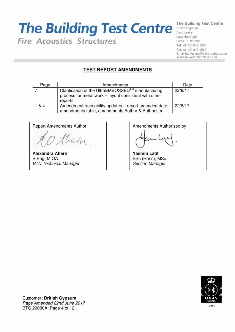
TEST REPORT AMENDMENTS
Page Amendments Date
7 Clarification of the UltraEMBOSSEDTM manufacturing process for metal work – layout consistent with other reports
22/6/17
1 & 4 Amendment traceability updates – report amended date, amendments table, amendments Author & Authoriser
22/6/17
Report Amendments Author
Alexandra Ahern B.Eng, MIOA BTC Technical Manager
Amendments Authorised by
Yasmin Latif BSc (Hons), MSc Section Manager

Customer: British Gypsum BTC 20080A: Page 5 of 12
The Building Test Centre British Gypsum
East Leake
Loughborough
Leics. LE12 6NP
Tel (0115) 945 1564
Fax (0115) 945 1562 Email [email protected] Website www.btconline.co.uk
TEST CONSTRUCTION The test specimen was constructed in an aperture having an overall opening of 2400mm (high) x 3600mm (wide). Gypframe 50FEC50 Folded Edge Standard Floor and Ceiling Channels were fixed to the head and base of the test aperture at 600mm centres using 25mm British Gypsum Drywall Screws. Gypframe 48S50 'C' Studs were positioned between the head and base channels at each end of the aperture and fixed using 25mm British Gypsum Drywall Screws spaced at 600mm centres. Gypframe 48S50 'C' Studs were positioned between the head and base channels at 600mm centres. The framework was clad with a double layer of 12.5mm Gyproc WallBoard each side. The inner layer of boards was screw fixed around the perimeter of the board at 300mm centres using 25mm British Gypsum Drywall Screws. The outer layer of boards was screw fixed around the perimeter of the board and the intermediate stud positions at 300mm centres using 35mm British Gypsum Drywall Screws. All vertical joints were staggered between layers. All joints and screw heads were taped and the perimeter was taped and sealed with Gyproc Sealant.

Customer: British Gypsum BTC 20080A: Page 6 of 12
The Building Test Centre British Gypsum
East Leake
Loughborough
Leics. LE12 6NP
Tel (0115) 945 1564
Fax (0115) 945 1562 Email [email protected] Website www.btconline.co.uk
Figure 1. Horizontal cross section view
The descriptions of individual components making up the test specimen were provided by the customer and were checked for accuracy wherever possible.
a) Double layer of 12.5mm Gyproc WallBoard.
b) Gypframe 48S50 'C' Studs @ 600mm c/c.
a) b)

Customer: British Gypsum Page Amended 22nd June 2017 BTC 20080A: Page 7 of 12
The Building Test Centre British Gypsum
East Leake
Loughborough
Leics. LE12 6NP
Tel (0115) 945 1564
Fax (0115) 945 1562 Email [email protected] Website www.btconline.co.uk
TEST MATERIALS Plasterboard i) Nominally 2400mm (long) x 1200mm (wide) x 12.5mm (thick) Gyproc WallBoard
manufactured by British Gypsum, ex East Leake. Surface density: 8.5kg/m2 Average thickness: 12.6mm Board Code: 16 089 17 11:08 16 089 17 11:07 16 089 17 11:07 The surface densities were calculated using the actual weight and size of a selection of the boards used in the test specimen. Material dimensions were supplied by the customer. Metal Components i) 0.5mm thick Gypframe 48S50 'C' Studs. ii) 0.5mm thick Gypframe 50FEC50 Folded Edge Standard Floor and Ceiling Channels All metal components are manufactured from galvanised mild steel using the ‘UltraEMBOSSEDTM’ process and supplied by British Gypsum. Fasteners i) 25mm British Gypsum Drywall Screws. ii) 35mm British Gypsum Drywall Screws. All fasteners supplied by British Gypsum. Miscellaneous Components i) Gyproc Sealant supplied by British Gypsum. ii) Joint tape supplied by The Building Test Centre. Where measurements could not be taken, then weight and dimensions were provided by the customer or the manufacturer e.g. from material labelling. Material information was recorded according to procedure AP070 vs 1.0.

Customer: British Gypsum BTC 20080A: Page 8 of 12
The Building Test Centre British Gypsum
East Leake
Loughborough
Leics. LE12 6NP
Tel (0115) 945 1564
Fax (0115) 945 1562 Email [email protected] Website www.btconline.co.uk
TEST RESULTS
Test Code Description
Weighted Airborne Sound Reduction Index
Rw (C; Ctr)
H20080AA Double layer of 12.5mm Gyproc WallBoard each side on
Gypframe 48S50 'C' Studs (Ultraembossed Profile). 42 (-3; -10) dB
For full data see Appendix A of this report. Test conducted in accordance with BS EN ISO 10140-2:2010 except for Clause A.2 in BS EN ISO 10140-4:2010 where minimum distances for measurements at frequencies under 100Hz cannot be met. Rated in accordance with BS EN ISO 717-1: 2013. No visible damage of the test specimen occurred during test. Testing to BS EN ISO 10140-2:2010 conforms to the requirements of BS EN ISO 140-3:1995 (withdrawn). Where the uncertainty of measured values is stated, (e.g. temperature, relative humidity and static pressure) the reported expanded uncertainty is based on a standard uncertainty multiplied by a coverage factor k=2, providing a coverage probability of approximately 95%. The uncertainty evaluation has been carried out in accordance with UKAS requirements.
TEST PROCEDURE The test specimen (3.6 m x 2.4 m) was constructed in a wall dividing two reverberant rooms of approximately 98m3 and 62m3. The accuracy of the test method conforms to BS EN 20140-2:1993, the test procedure used is detailed in the test data in Appendix A of this report. Broad-band white noise was used to measure the level differences and broad-band pink noise was used to measure the reverberation times. Third octave band pass filters were used in real time mode. See appendix B for further information.
LIMITATIONS The results only relate to the behaviour of the element of construction under the particular conditions of test; they are not intended to be the sole criteria for assessing the potential acoustic performance of the element in use nor do they reflect the actual behaviour.

Customer: British Gypsum BTC 20080A: Page 9 of 12
APPENDIX A - TEST DATA
Test Code:
H20080AATest Date:
Freq. R
Hz dB
50 24.2
63 19.0
80 14.1
100 15.1
125 17.5
160 28.1
200 30.6
250 29.5
315 33.5
400 40.1
500 44.6
630 45.9
800 50.0
1 000 51.2
1 250 54.0
1 600 57.0
2 000 58.6
2 500 53.2
3 150 45.2
4 000 47.6
5 000 51.8
Rating according to Rw (C;Ctr) = 42 (-3;-10) dBBS EN ISO 717-1:2013 Max dev. 8.5 dB a t 125 Hz
Evaluation based on laboratory C50-3150= -4 dB C50-5000= -3 dB C100-5000= -2 dB
measurement results obtained by
an engineering method: Ctr,50-3150= -12 dB Ctr,50-5000= -12 dB Ctr,100-5000=-10 dB
Curve of reference values (ISO 717-1)
16/05/17
0
10
20
30
40
50
60
70
63
125
250
500
1 0
00
2 0
00
4 0
00
Sound R
eductio
n In
dex, R
, dB
Frequency, Hz

Customer: British Gypsum BTC 20080A: Page 10 of 12
Test Code: H20080AA Test Date:
Room T2 Room T1
Specimen Area, S = 8.64 m2
Room Volume, m3: 98 60.14
Temperature, deg.C: 18.6 18.9 ± 0.3
Rel. Humidity, %RH: 65.7 67.1 ± 1.6
Static Pressure, Pa: 101400 101400 ± 65
Test Room T2 to Test Room T1 R
Freq Source Rec. (uc) Bgrnd Rec. (corr) Rev.time Corr. R U.Dev. 1/1Oct
Hz dB dB dB dB Sec dB dB dB dB
50 59.4 33.6 26.0 32.8 0.64 -2.4 24.2
63 64.5 44.3 23.3 44.3 0.85 -1.2 19.0 17.3
80 74.0 57.1 13.3 57.1 0.58 -2.8 14.1
100 79.0 62.6 8.9 62.6 0.82 -1.3 15.1 7.9
125 100.6 82.2 3.4 82.2 0.91 -0.9 17.5 8.5 17.8
160 85.2 57.2 3.6 57.2 1.15 0.1 28.1 0.9
200 90.2 60.5 15.5 60.5 1.37 0.9 30.6 1.4
250 92.0 63.8 3.6 63.8 1.50 1.3 29.5 5.5 30.9
315 91.7 59.4 5.5 59.4 1.47 1.2 33.5 4.5
400 90.9 51.9 16.8 51.9 1.45 1.1 40.1 0.9
500 89.5 46.4 4.0 46.4 1.57 1.5 44.6 42.8
630 88.0 43.5 4.2 43.5 1.53 1.4 45.9
800 88.9 40.3 3.4 40.3 1.52 1.4 50.0
1 000 88.7 38.9 10.8 38.9 1.53 1.4 51.2 51.4
1 250 89.3 36.9 2.8 36.9 1.60 1.6 54.0
1 600 92.1 36.7 3.2 36.7 1.62 1.6 57.0
2 000 93.9 37.0 4.2 37.0 1.63 1.7 58.6 55.7
2 500 92.6 40.5 3.3 40.5 1.45 1.1 53.2
3 150 91.9 47.4 4.4 47.4 1.31 0.7 45.2 0.8
4 000 92.7 45.9 8.4 45.9 1.33 0.8 47.6 47.4
5 000 97.3 46.2 11.3 46.2 1.31 0.7 51.8
6 300
8 000
10 000
Single Figure Ratings Rw C Ctr Total U. Dev., dB 30.4
BS EN ISO 717-1: 2013 dB dB dB
42 -3 -10Tested By:_______________________
(100-5000) -2 -10Checked By:______________________
Background Corrected (50-3150) -4 -12Procedure: AP 047 vs 1.0
(50-5000) -3 -12 Worksheet: 140_3_1.XLS
LABORATORY AIRBORNE SOUND INSULATION TEST - BS EN ISO 10140-2:2010
16/05/17

Customer: British Gypsum BTC 20080A: Page 11 of 12
APPENDIX B - TEST METHOD AND CONDITIONS Method The average sound pressure level in each 1/3 octave band is measured using a rotating microphone boom, positioned such that the minimum distance between microphone and sound source is 1m and between microphone and room boundaries is 0.7m. The rotating microphone has a sweep radius of at least 1m and is inclined in relation to the boundaries at an angle of at least 30o to the horizontal. The microphone has a traverse time of 32 seconds, and the sound pressure levels are averaged over 64 seconds which is equivalent to two complete sweeps of the microphone boom. The equivalent absorption area of the receiving room is determined by producing the arithmetic average of twelve reverberation times and applying this to the Sabine formula. Test Chamber Layout The test suite is constructed to be as independent from the surround building as is physically possibly in order to minimise flanking transmission paths.
The source room (T2) contains two perspex diffusers of approximately 900mm x 1220mm. Panel absorbers are used to ensure reverberation times in source room (T2) are between one and two seconds at all frequencies at and above 100 Hz. An omni-directional loudspeaker sound source is placed near a back corner of the source room (T2), rotating at 1 rpm and at least 0.7m from any room boundary. A stationary loudspeaker sound source is placed in the corner of the receiving room (T1) opposite the test specimen.
Side Elevation Plan view
Test Chamber Shape

Customer: British Gypsum BTC 20080A: Page 12 of 12
Mounting The BTC has a solid concrete frame which has been additionally lined to give improved reduction of flanking transmission. This is in order to ensure that, as far as possible, lab limits will not restrict the real performance measurement of just the test specimen. Recommendations for installation position within the niche are given in our Installation Guidance Document. Details of actual installation position are held by the BTC in the Test Report folder. Cross section of test aperture Lab Limits The laboratory limit for measurement due to flanking is (combined BTC 11709A, BTC13562EA, BTC 15829A and BTC 19792A).
Freq Hz
50 63 80 100 125 160 200 250 315 400 500 630 800 1000 1250 1600 2000 2500 3150 4000 5000
R'max 45.0 46.9 58.5 62.4 62.9 67.7 71.2 77.2 84.2 92.0 97.7 101.5 103.8 97.6 102.4 104.8 101.8 102.9 98.7 96.4 96.3
Uncertainties for test The uncertainties values for test are taken from ISO 12999-1 situation B situ standard deviation.
Freq Hz
50 63 80 100 125 160 200 250 315 400 500 630 800 1000 1250 1600 2000 2500 3150 4000 5000
Standard Uncertainty
4.0 3.6 3.2 2.8 2.4 2.0 1.8 1.6 1.4 1.2 1.1 1.0 1.0 1.0 1.0 1.0 1.0 1.3 1.6 1.9 2.2
Descriptor Rw Rw + C
(100-3150)
Rw + Ctr
(100-3150)
Rw + C
(100-5000)
Rw + Ctr
(100-5000)
Rw + C
(50-3150)
Rw + Ctr
(50-3150)
Rw + C
(50-5000)
Rw + Ctr
(50-5000)
Standard Uncertainty
0.9 0.9 1.1 1.1 1.1 1.0 1.3 1.1 1.0
24
5
90
580
90
58
0
90
560
90
245
59
0675
24
00
660