Embed Size (px)
Citation preview
MRWA SEWERAGE STANDARDS
VERSIONISSUED
MELBOURNE RETAIL WATER AGENCIESDATE:
DATE:
CHECKED:DRAWN:DESIGNED:
1 2 6 7 8 9 10 12113 4 5
H HGWW
SEW
YVW
DATENAME APPROVED:
GWW
SEW
YVW
DATENAME
APPROVEDDATEDESCRIPTIONREV
A
1 2 63 4 5
B
C
D
A
E
F
G
1 2 6 7 8 9 10 12113 5
A
B
C
D
E
F
G
H
Planning Design Construction
R. JAGGERR. JAGGER
D. MOOREC. PAXMANK. DAWSON
R. CARRUTHERS
J. TOMASI
1 JULY 20151 JULY 2015
PRE-PUBLISHED DRAFT1
2 PUBLISHED FIRST ISSUE 01/10/15 CP / JT / KD / RJ
2015 1CP / JT / KD / RJ
D. O'DONOVAN01/09/1501/09/1501/09/15
01/09/1501/09/1501/09/1501/03/15
ALL DIMENSIONS IN mm UNLESS STATED OTHERWISE NOT TO SCALE
SEWERAGE NETWORKAIRFLOW MANAGEMENT
MRWA-S-401
TABLE 401-A: HYDROGEN SULPHIDE RISK CONTROL
· Limited or no property boundary traps or water seals.· Natural ventilation.
SYSTEM TYPEOPEN SYSTEM(LOW RISK ASPER TABLE 401-C)
RELEVANT SYSTEM DESIGN RULES (REFER TABLE 401-D)
CLOSED SYSTEM(MED / HIGH RISK AS
PER TABLE 401-C)
MED RISKHIGH RISK
Seal system to contain gas where hydrogensulphide production cannot be adequatelycontrolled.
· Use property boundary traps &/or water seals at all:·· Junctions of properties and closed systems.·· Junctions of closed systems and open systems.
· Ventilation requires air treatment.MHs require coating protection as per Table 307-E.MHs constructed of geopolymer concrete, plastic or lined as per Table 307-E
PRINCIPLE OF H 2S RISK CONTROL
Odour:Disperse H
2S at multiple locations while concentrationsremain low.Concrete Corrosion: Keep pipe wall dry (maintain a lowrelative humidity in the head space of the seweragesystem) to reduce the formation of sulphuric acid.
NOTES Regarding H₂S Risk Assessment of Sewage:· This assessment needs to be completed for each sewer, starting from the upstream ends of the
catchment and working downstream.· Formula for calculating risk of intersecting flow is as follows:
RISK (H₂S) = F 1 / (F
1 + F 2) x (A
1 + B 1 + C
1) + flow is ADWF F
2 / (F 1 + F
2) x (A 2 + B
2 + C 2) + D (Refer Figures 401-B & C).
· All concrete manholes in closed systems shall be protected as per Table 307-E.
RISK LEVELPOINTS > 6
HIGH RISKTABLE 401-C: H
2S RISK SCORES
> 3 & <6MEDIUM RISK
· Low risk sewers typically should be open.· Medium and High risk sewers typically
should be closed.< 3LOW RISK
DN375 OPENSYSTEM
BT
BT
BT
BT AREA
BT A
REA
BT
BTBT AREA
BT AREA
BT
BT
BT AREA
BT AREA
BT AREA
OPEN RETIC MAINLEGEND
OPEN BRANCH SEWER (> DN300)
CLOSED BRANCH SEWER (> DN300)
WATERSEAL
PRESSURE MAIN
HIGH B.O.DCUSTOMERCONNECTION
HYBRIDPRESSURESEWERAGE/ GRAVITYSYSTEM
PUMP STATION WITHCHEMICAL DOSING
BT BOUNDARYTRAP AREA
TABLE 401-D: SYSTEM DESIGN RULESRULE
VENTS ON OPENBRANCH SEWERS
VENTS ONCLOSED BRANCHSEWERS
Not typically required (unless pressure main discharge point orsewer terminates at a wet well).Where required, forced ventilation with air treatment is requiredunless there is a significant buffer of land around vent (ie: > 100m).Upstream end of ventilated Closed System requires ventilation withan induct.
RULE DESCRIPTIONInstall a vent at the MH upstream from water seals which terminateat open branch sewers.Install vents on open branch sewers (> DN300) at 1000m spacing(without air treatment).
1
2
BOUNDARY TRAP(BT) AREAS
Required where: 1) a retic sewer which contains < 5 propertyconnections discharges to a closed system, or 2) the propertyconnects directly to a closed system, or 3) a retic sewerdischarges to an established BT area.
3
FORCEDVENTILATION +AIR TREATMENT
SPS WET WELLVENTILLATION
Typically, at least natural ventilation will be required at sewagepump stations.Forced ventilation with air treatment may be required where:1) Detention time within the wet well is excessive, or 2) the SPSis in a built up area with limited buffer, or 3) the sewage enteringthe SPS presents a medium or high risk.
4
Where the combined flow from an Open and Closed system isconsidered low risk:1) the downstream system shall be considered an Open system,2) install a water seal just upstream of the junction on the Closedsystem.
Where the combined flow from an Open and Closed system isconsidered a medium or high risk:1) the downstream system shall be considered a Closed system,2) install a water seal just upstream of the junction on the opensystem. Refer Figure 401-B.
JUNCTION OFOPEN & CLOSEDSYSTEMS
5
VENT
Vent and treat air at the discharge of pressure mains inaccordance with the calculated risk level and Table 317-B.
DISCHARGE OFPRESSURE MAINS
6
FIGURE 401-C: EXAMPLE 2 OF H₂S RISK ASSESSMENT
RISK SCORE =(4050 x 3) + (10
50 x 0)= 2.4
DETENTION = 6 HRSRISK SCORE = 2.4 + 2= 4.4
FIGURE 401-A: EXAMPLE SEWERAGE NETWORK AIRFLOW CONFIGURATION
REFERRULE 1
REFERRULE 4
REFERRULE 1
REFERRULE 6
F 1 = 10 l/s
0 POINTS
F 2 = 40 l/s
3 POINTS
RISK FACTORDESCRIPTION
AGE OFSEWAGE
SEWAGECONTENTS
VENTILATION&TURBULENCE
SEWER < DN300
IND / COMM- SIGNIFICANT B.O.D DISCHARGE
UPSTREAM SYSTEM IS OPEN
KEYCONSIDERATIONS
NO.POINTS
23
601
TABLE 401-B: HYDROGEN SULPHIDE RISK FACTORSFACTOR
A
B
CIND / COMM HIGH B.O.D DISCHARGE
SEWER DN375SEWER DN450 to DN600
SEWER > DN800
0
> 90% RESIDENTIAL
2
CLOSED U.S BRANCH SEWERS HAVE MINIMAL DROP
PRESSUREMAINDETENTIONTIME
SEWER IS NOT A PRESSURE MAIND< 4 HRS AT ADWF4 to 7.9 HRS AT ADWF
> 12 HRS AT ADWF
0234
12
6
0
FOR GRAVITY SEWERS
FOR PRESSURE MAIN INFLOWS
CLOSED U.S BRANCH SEWERS HAVE MODERATE DROPCLOSED U.S BRANCH SEWERS HAVE HIGH DROP
· sewer DN300· residential· open system= 0 points
· sewer < 375· significant B.O.D· closed system with
minimal drops= 3 points
4.4 points(add 2 points due topressure maindetention)
2.4 POINTS
FIGURE 401-B: EXAMPLE 1 OF H₂S RISK ASSESSMENT
RISK SCORE =(4050 x 0) + (10
50 x 3)= 0.6
F 1 = 40 l/s
0 POINTS
F 2 = 10 l/s
3 POINTS
· sewer < 375· residential· open system= 0 POINTS
· sewer < 375· significant B.O.D· closed system with
minimal drops= 3 POINTS
0.6 POINTS
CLOSEDSYSTEM
CLOSEDSYSTEM
RISK SCORE =(200250 x 5) + ( 50
250 x 0.6)= 4.1
· sewer DN375· significant B.O.D· closed system with
minimal drop= 5 POINTS
F 3 = 200 l/s
5 POINTS
VENTILATION +INDUCT
REFERRULE 2
HYBRIDPRESSURESEWERAGE/ GRAVITYSYSTEM
BT
3 UPDATED RISK SCORING CP / GA / RLSEP 20
· Factor A: Sewer size is usually provides a good approximation for sewerage age.· Factor B: discharges high in B.O.D typically come from production plants processing food, animal or
petrochemical products (eg: juice, leather, wool, meat, wine, beer etc).· Factor C: Turbulence is typically beneficial in Open Systems.
Exclude vortex drops.Minimal drop is < 5m of cumulative drop in upstream branch sewer MHs.Moderate drop is 5 to 10m of cumulative drop in upstream branch sewer MHs.High drop is >10m of cumulative drop in upstream branch sewer MHs.
· Factor D: Pumped flows which have been chemically treated for H 2S suppression shall be
considered not to or only partially increase H 2S risk.
8 to 12 HRS AT ADWF 4
4SEWER DN675 to DN750
REFERRULE 4
PUMP STATION
CLOSED RETIC MAIN
BT AREA
VERTICAL VENTTUBE REFERTABLE 402B-A
FOR CONCRETE NOTESREFER MRWA-S-402.
PILE LENGTH AS PERTABLE 402B-B
FSL
MIN COVER AS PERMRWA-S-201
150
CUT AND REMOVE REINFORCEMENTWHICH INTERFERES WITH VENTPIPEWORK. INSTALL ADDITIONAL BARS,REFER NOTE C3 ON MRWA-S-402
REINFORCED CONCRETE PILE
75 M
IN C
OVER
.10
0 MAX
. (TY
P.)
NOTE : NOT ALLVERTICAL BARS SHOWN
FOR CLARITY
SPIRAL LIG N8 (MIN.)HELIX 150 PITCH. 1.5
EXTRA TURNSTOP AND BOTTOM
FALL (5%)MIN SN8 PVC DWV PIPE TOAS/NZ 1266 (RRJ). SIZE AS PERMRWA-S-402B-C
900
L (RE
F TA
BLE
402B
-A)
STAINLESS STEEL (SS) DOUBLE NUTSWITH SS DOME NUTS TO FINISH. REFERFOUNDATION NOTES ON MRWA-S-402
HOLD DOWNBOLT CAGEREF FIG 402B-G
NOTE: * DENOTES MINIMUM SOCKET LENGTH INTO ROCK
RUBBER RING JOINTS
BLINDING LAYERREFER MRWA-S-402
FOUNDATION NOTES
LOCATING RINGS, AS REQUIRED6 THICK SS, TOP AND BOTTOM WITHSUITABLE LOCK NUTS TO ALLOWTHREADED ROD ADJUSTABILITY
IF HOLD DOWN BOLT CAGE (CIRCULAR) ANDVENT PIPE CLASH LOCALLY, A MAXIMUM OFTHREE No. HOLD DOWN BOLT EMBEDMENTMAY BE REDUCED FROM 600mm TO 400mm.COVER TO BOLTS TO BE MAINTAINED.
HOLD DOWNTHREADED
RODS, SS316
600 E
MBED
MENT
INTO
PILE
12 N20 VERTICALBARS EQUISPACED
100
10 THICK GUSSET PLATE EQUISPACED(REFER FLANGE MOUNTING DETAIL)Ø20 HOLES (X4)FOR GROUT INSERTION
HOLES FOR HOLDDOWN BOLTS,REFER TABLE 402-A
30 THICK BASE PLATE
101
12
5
3
79 2
11
6
4
8
TIGHTENING SEQUENCE
50
OD
1200
115
VENT TUBEREFER TABLE 402B-A
1.6 THICKCOVER PLATE
ANEMOMETER OPENING.FIX COVER TO VENT SHAFTWITH 4 x M8 TAMPER PROOFx 25 FULLY THREADEDFASTENERS THROUGHTHREADED HOLES IN VENTSHAFT. INSTALL WITHSPRING WASHERS.
1m MIN TO ANY EXISTING OR NEWSTRUCTURES. DO NOT UNDERMINE.REFER MRWA-S-402 FOUNDATION NOTES.
60°HEIG
HT: R
EFER
MRW
A-S-
402 V
ENT
NOTE
S
PCD
COWL, REFERMRWA-S-402
UPPER FLANGEJOINT, IF REQUIRED
8 BOLT ARRANGEMENT SHOWN,REFER TABLE 402B-A
PCD
OD
FULL STRENGTHBUTT WELD
1
2
34
5
67
8TIGHTENING SEQUENCE
20 THICK FLANGE PLATES. INSTALL 3THICK EDPM RUBBER GASKETBETWEEN UPPER FLANGE FACES
65MAX
65MAX
MAX.
>2000 MIN. CLEARANCETO ANY STRUCTURE
FOR HEIGHT, REFER MRWA-S-402NOTES FOR GUIDANCE. HEIGHTTO BE < THE MAXIMUM NOTED INTABLE 402B-A.
-
-
SPIRAL LIG N6 HELIX 150PITCH. 1.5 EXTRA TURNSTOP AND BOTTOM
12 x N20 BAR, EQUISPACED
BOLT END PLATESREFER TABLE 402B-D
REMOVE AS LITTLEREINFORCEMENTAS PRACTICAL
ADD ADDITIONAL N20 VERTICALBAR BOTH SIDES, 1500 LONG.REFER NOTE C3 ON MRWA-S-402
900
20
GUSSET PLATE, 10 THICK
VENT TUBE(REFER TABLE402B-A)
20 X 20 CUT OUT
SN8 PVC DWVPIPE, SIZED TOMATCH VENTTUBE.
50 MPa NON SHRINKAGECEMENTITIOUS
FLOWABLE GROUT
HOLD DOWN BOLT AS PERTABLE 402B-A,
4 THICK WASHERS ANDDOUBLE NUTS OR LOCK NUTS
D (DIAMETER)
50
130
30
600
RUBBER CAP
BOLT END PLATEREFER TABLE 402B-D
FIGURE 402B-B: TYPICAL UPPER LANGE DETAIL
FIGURE 402B-A: VENT SHAFT (ELEVATION)
FIGURE 402B-C: VENT TUBE BASE PLATE DETAIL
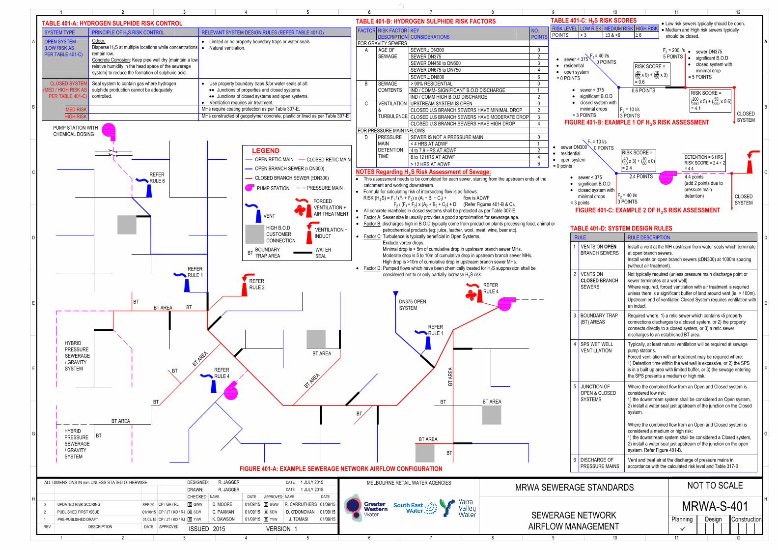
FIGURE 402B-D: VENT SHAFT FOUNDATION DETAILS (ELEVATION)
FIGURE 402B-E: SECTION 1
FIGURE 402B-G: HOLD DOWN BOLT CAGEDETAIL (ELEVATION)
FIGURE 402B-F: SECTION 2
75 MIN COVER100 MAX COVER
TABLE 402B-B: FOUNDATION PILE LENGTH FOR DIFFERENT SOILS (m)SOIL / ROCKTYPE
COHESIVE
GRANULAR
DESIGNPARAMETER
C U = 25 kPa
CONSISTENCY/ STRENGTH
FIRM
WEATHEREDROCK
STIFF
VERY STIFF
ɸ' = min 30°
HARD
LOOSE TO DENSEUSC < 0.5 MPa VERY LOW
LOW
3.2
150
2.5
2254.03.0
2.11.8
2.62.0
2.2 (1.3 *)1.8 (0.9 *)
3.53.0
1.6 (0.7 *)1.5 (0.6 *)
C U = 50 kPa
C U = 100 kPa
C U = 200 kPa
USC < 2.0 MPa
300
3.8
5.0
2.4
3.0
2.4 (1.5 *)
4.0
1.8 (0.9 *)
NOMINAL VENT DIAMETER
TABLE 402B-A: VENT TUBE, BASE PLATE AND UPPER FLANGE DETAILSNOM VENTDIAMETER
150
D.S SEWERAGEMAIN SIZE (DN)
225 to 375
MAX HEIGHT (m)
14
18
18
273.1
SCH
S40
O.D
168.3S80
323.9S40
450 to 525
600 to 750
I.D
254.6
146.4
304.8
VENT TUBE56 m/s
9
12
14
89 m/s
225
300
500
O.D
580
PCD
400480
550630
NO. HOLES
12
12
16
BASE PLATE
28
HOLE Ø
24
28
BOLT
M24
M20
M24
356
O.D
405
PCD
235280
406455
NO. HOLES
8
8
12
UPPER FLANGE
22
HOLE Ø
18
22
BOLT
M20
M16
M20
< 10m
10 to 25m
25 to 50m
TOTAL LENGTHAS VENT NOMINAL DIAMETER IN TABLE 402B-A
ON SIZE LARGER THAN NOMINAL VENT DIAMETER
TWO SIZES LARGER THAN NOMINAL VENT DIAMETER
BURIED VENT PIPE DIAMETERTABLE 402B-C: BURIED VENT PIPE DIAMETER
M20
M24
BOLT DIAMETER75
90
D
TABLE 402B-D: BOLT CAGEEND PLATE DIMENSIONS
12
16
T
FIGURE 402B-H: FLANGE MOUNTINGDETAIL (ELEVATION)
NOTES Regarding Table 402B-C:· Total length = vent tube length + buried
vent length.· If buried vent pipe > DN450, construct
buried vent pipe from PP or GRP.· Refer MRWA-S-103 for standard sizes
and determining what one size or twosizes larger mains.
· Transition to larger sized buried vent pipe&/or different material pipe usingapproved couplers and adaptors.
MRWA SEWERAGE STANDARDS
VERSIONISSUED
MELBOURNE RETAIL WATER AGENCIESDATE:DATE:
CHECKED:DRAWN:DESIGNED:
1 2 6 7 8 9 10 12113 4 5
H HGWWSEWYVW
DATENAME APPROVED:GWWSEWYVW
DATENAME
APPROVEDDATEDESCRIPTIONREV
A
1 2 63 4 5
B
C
D
A
E
F
G
1 2 6 7 8 9 10 12113 5
A
B
C
D
E
F
G
H
Planning Design Construction
R. JAGGERR. JAGGER
PRE-PUBLISHED DRAFT FROM PARENT 40212 PUBLISHED FIRST ISSUE FROM PARENT 402SEP 20 CP / GA / RL
2020 1CP / GA / WSNOV 19
ALL DIMENSIONS IN mm UNLESS STATED OTHERWISE NOV 2019NOV 2019
G. ANTHONSENC. PAXMANW. SHIMMIELD
S. TRIKHA
R. LEOND. STEWART
SEP 20SEP 20SEP 20
SEP 20SEP 20SEP 20
NOT TO SCALE
VENT CONSTRUCTION DETAILSMRWA-S-402B
10 to 25m
AS LO
NG A
S PO
SSIB
LE. T
YPIC
ALLY
6m A
VAILA
BLE
FIGURE 402B-I: GROUND LEVEL VENT ARRANGEMENT(ISOMETRIC CUT THROUGH CENTRE)
· Only place ground level vents in non-trafficable areas.· Ground level square grate shall be galvanised steel class B.· Sealed lower level covers and frames as per Figures 301-B (DN150 &
DN225) and Figure 305-C (DN300) with DWV cap removed.· Set level of lower cover and frame to maintain > 30 clearance between the
top of the Air Admittance Valve and the underneath of the grated cover.· Lower cover: solid top class D, bolted down with 50Ø equi-spaced holes
drilled through cover midway between load bars (ribs) of cover.· BSP thread tap the 50Ø cover holes and fit Air Admittance Valves.· < DN225 vents require 4 holes and Air Admittance Valves in the cover.· DN300 vents require 6 holes and Air Admittance Valves in the cover.· Cover FSL shall be as per Table 313-E.
FRAME & CONCRETE SURROUNDFOR GRATED COVER
SHROUD
AIR ADMITTANCE VALVES
FRAME AND CONCRETESURROUND FOR SOLID
TOP COVER
GRATED SQUARECOVER AT FSL
>30
SOLIDTOP
COVER
Ø50 HOLESTAPPED WITHBSP THREAD
INTERNALDIAMETER
50 - 100
10 T
MRWA SEWERAGE STANDARDS
VERSIONISSUED
MELBOURNE RETAIL WATER AGENCIESDATE:
DATE:
CHECKED:DRAWN:DESIGNED:
1 2 6 7 8 9 10 12113 4 5
H HGWW
SEW
YVW
DATENAME APPROVED:
GWW
SEW
YVW
DATENAME
APPROVEDDATEDESCRIPTIONREV
A
1 2 63 4 5
B
C
D
A
E
F
G
1 2 6 7 8 9 10 12113 5
A
B
C
D
E
F
G
H
Planning Design Construction
R. JAGGERR. JAGGER
D. MOOREC. PAXMANK. DAWSON
R. CARRUTHERS
J. TOMASI
1 JULY 20151 JULY 2015
PRE-PUBLISHED DRAFT1
2 PUBLISHED FIRST ISSUE 01/10/15 CP / JT / KD / RJ
2015 1CP / JT / KD / RJ
D. O'DONOVAN01/09/1501/09/1501/09/15
01/09/1501/09/1501/09/1501/03/15
ALL DIMENSIONS IN mm UNLESS STATED OTHERWISE NOT TO SCALE
VENTS - GENERALMRWA-S-402
FOUNDATION NOTES:F1. Pile standards are not suitable in aggressive soil conditions such as acid sulphate soils, salt rich soils and
soils in areas affected by salinity.F2. Pile standards designed for ultimate limit state loading and it has been assumed not to be sensitive to
deflection.F3. The designer shall nominate the required pile length and the assumed ground conditions.F4. A qualified geotechnical engineer shall inspect the pile excavation and confirm that the ground conditions
encountered on site are consistent with those nominated by the designer and the pile length proposed(refer Table 402B-B). This standard allows for 900mm depth of low resistance soil from surface toaccommodate for variable or poor near surface soils.
F5. Design advice to be sought should the piles by installed on sloping ground (> 1 in 7), below groundwatertable, on fill material or within 2m of slope crest.
F6. The drilled shaft shall be clean of loose debris, top soil, root material, water or collapsed material prior toplacement of concrete.
F7. Contractor shall not commence excavation if a rain event is forecast that day.F8. Pile excavation shall not be left open for more than 24 hours. Design advice shall be sought for delays in
pouring concrete under exceptional circumstances.F9. Where the foundation becomes softened or loosened due to adverse weather, ground seepage, or other
causes, all soft or loose materials shall be removed down to where the encountered ground conditions areas nominated by the designer and replaced by 6% cement stabilised sand or concrete.
F10. Any over excavation shall be backfilled with blinding concrete class N-20 mass concrete to AS 1379.Blinding concrete shall be placed as soon as possible within 24 hrs following excavation to avoid softeningor drying out of the base soil.
F11. Excavation near existing footings shall not extend below the footing base level without approval of thefooting's asset owner. Any such potential undermining conditions shall be referred to the footing's assetowner immediately for resolution.
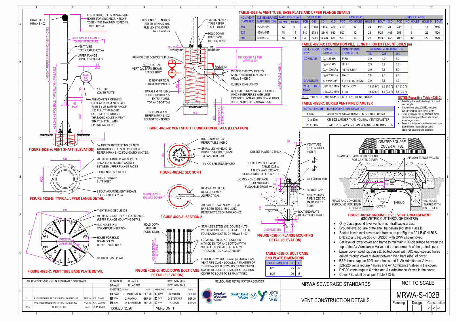
DESIGN WIND SPEED NOTES:D1. The vent stack structural design has been designed on the basis of the following:
i) design wind speed of 89 m/s has a resulting design wind pressure of 3.7 kpaii) design wind speed of 56 m/s has a resulting design wind pressure of 1.5 kpa
D2. Wind speed to be determined by a suitably qualified and experienced structural engineer in accordance withAS 1170.2 Structural Design Actions: Wind Actions.
D3. As a guide only, the two factors affect the wind speed category of a site: Terrain Category (TC) andTopography Multiplier (MT).
D4. Terrain Categories are defined in AS 1170.2: 2011 (AMD 5) and can be summarised as :a. Category 1: Very exposed open terrain with few or no obstructions. e.g. flat, treeless, poorly grassed
plains; rivers, canals and lakes.b. Category 2: Open terrain, including grassland, with well scattered obstructions having heights generally
from 1.5m to 5m.e.g. farmland and cleared subdivisions.
c. Category 2.5: Intermediate between TC2 and TC3 and represents the terrain in developing outer urbanareas with scattered houses, or large acreage developments with fewer than ten buildings per hectare.
d. Category 3: Terrain with numerous closely spaced obstructions having heights generally from 3m - 10m.e.g. suburban housing with at least 10 house sized obstructions per hectare or light industrial estates.
e. Category 4: terrain with numerous large, high (10 - 30m tall) and closely spaced obstructions such aslarge city centres and well developed industrial complexes.
D5. Topographic Multiplier (MT) ranges from 1.0 (minimum, classed as not on a hill) to 1.71 (maximum).D6. The relationship between MT and TC can be seen in Table 402-A.
Note, this is valid for the Melbourne region only (A1 - A5), a design life of 50 years and importance level 2.
VENT & COWLING SELECTION NOTES:V1. For sewage mains > DN750, a custom vent stack design shall be completed.V2. Vent location, colour and height to be determined in consultation with the applicable Water Agency.
Specifications for these requirements shall be established on a case-by-case basis.V3. Vent colour is recommended to match the existing environment that it is placed in, noting the colour of
surrounding buildings and existing utility poles.V4. A risk assessment (which may include odour dispersion modelling) shall be undertaken to establish an
appropriate height for the vent stack and the type of cowling. It shall consider the risk level of the sewage (referMRWA-S-401), the position of the vent in the network, TC and MT, nearby vegetation, nearby buildings andland use.As a guide:· Vents with air induct cowls may be reduced to 3m in height.
Such vents will typically be the upper most vents in the system and so are typically air induct vents.· Vents shall extend 2m above the height of adjacent buildings.
A building is considered adjacent to the vent stack if it is within five times the minimum of projectedbuilding width or building height (whichever is greater).The projected building width is indicated in the Figure 402-C.
· Vents shall extend above the vegetation canopy.· Vents shall be > 7m high in open parkland.· Vents shall be > 9m high in residential areas.· Vents shall be > 12m high in high density areas or public thoroughfares.· Vent height may be reduced where there is air treatment &/or forced ventilation..
STEELWORK & FASTENER NOTES:S1. All workmanship and materials to be in accordance with AS 4100 (steel structures), AS 1554 (structural
welding) and AS 4855 (weld consumables).S2. The inspection and testing of all welds shall be carried out by qualified personnel in accordance with AS 2214.S3. All plates to be stainless steel grade 316L to ASTM A240 uno.S4. Vent stack to be stainless steel grade 316L to ASTM A312 uno.S5. Vent steelwork to be matt finish. Glass bead blast abrade to RA 3.5 to 4.5 micron surface roughness.
Do not paint unless directed by the Water Agency.S6. All fasteners to be stainless steel grade 316L (A4) to ASTM A276 uno.S7. All bolts shall be of such length that at least two full threads are exposed beyond the nut after the nut has been
tightened.S8. Fasten lower flange to snug fit.S9. Fasten upper flange using the part-turn method or load indicating washers in accordance with AS 4100.
Calibrated torque wrenches shall not be used. A hardened washer shall be used under the bolt head or nut,whichever is rotated. The reuse of fully tensioned bolts is prohibited.
S10. Hammer pin welds and tow grind all welds after the cessation of welding.S11. No stop-start positions of the weld within 40mm of the end of the stiffener.S12. Vent tubes shall be joined using only the prescribed flange joint as per Figure 402B-B.
Vent tubes shall not be welded together.S13. Minimise the number of vent tube joints by using vent tube of the longest available length (typically 6m).
CONCRETE NOTES:C1. Refer to MRWA-S-309 for concrete and reinforcement requirements in addition to those stated within
MRWA-S-402B and the notes below.C2. Pouring of concrete shall be in a single pour.C3. Longitudinal reinforcing bar to be locally cut to avoid clash with penetrating pipe. Additional
longitudinal bars are to be added either side of penetrating pipe and be lapped 750mm min with the cut barabove and below pipe. Ligatures are to be locally cut around penetrating pipe.
C4. All reinforcement shown in MRWA-W-402B is represented diagrammatically and not necessarily shown intrue projection.
C5. Erect vent stack when concrete base is greater than 25 MPa strength.
TABLE 402-A: WINDSPEED (m/s)
56
2.5
56
TOPO
GRAP
HIC
MULT
IPLIE
R (M
T)
TERRAIN CATEGORY (TC)
1.0
1.1
1.2
1.0
56
56
3.0
56
2.0
56
56
56
4.0
56
56
56561.3
1.4
56
89
5656
56
56 56
56
89891.5
1.6
89
89
8989
89
89 89
89
89891.71
89
89
8989
89
89 89
89
WIRE 2.5Ø, SPOT WELDED TO RIBS ATALL INTERSECTIONS
VENT SHAFT
30NECK SLEEVE, 1.6 THICK.SNUG FIT INTO VENT SHAFT.
WIND VANE DESIGNED TO ENSUREOPENING FACES INTO THE WIND.SURFACE AREA > 2 x p(VENT R)2
COWL TO ROTATE FREELY RELATIVETO VENT SHAFT USING 2 x Ø15 SS316BEARINGS LOCATED IN THROAT OFINTERNAL SPIDER STRUT.
OPENING ROTATES TO FACE WINDDIRECTION.COVER OPENING WITH 10 x 10 SS316OR 304 MESH IF LESS THAN 3m ABOVEGROUND.
VENT SHAFT Ø + 100
6 OR MORE U SHAPED RIBS, 4 THICK.SECURELY SPOT WELD TO NECK ATALL INTERSECTIONS.
FIX COWL TO VENT SHAFT WITH 8 x FULLYTHREADED M6 x 25 FASTENERS THROUGHTAPPED HOLES IN VENT SHAFT. INSTALLWITH SPRING WASHERS.
FIX COWL TO VENT SHAFT WITH 4 x SS316FULLY THREADED M6 x 25 FASTENERSTHROUGH TAPPED HOLES IN VENT SHAFT.INSTALL WITH SS316 SPRING WASHERS.
NOTE: ALL MATERIALS TO BE GRADE SS316
FIGURE 402-A: EDUCT COWL ELEVATION (NTS)
NOTE: ALL MATERIALS TO BE GRADE SS316
FIGURE 402-B: ROTATING INDUCT COWL (ISOMETRIC) (NTS)
BUILD
ING
VENT STACK
FIGURE 402-C: ADJACENT BUILDING EXAMPLE (NTS)
A = DISTANCE TO BUILDING
(AT CLOSEST POINT)
B = PROJECTED WIDTH(FROM NORMAL TO BUILDING CENTRE)
Building is adjacent as A < 5 x B
3 ADD DETAILS. REMOVE STRUCTURAL FIGS CP / GA / RLSEP 20
MRWA SEWERAGE STANDARDS
VERSIONISSUED
MELBOURNE RETAIL WATER AGENCIESDATE:
DATE:
CHECKED:DRAWN:DESIGNED:
1 2 6 7 8 9 10 12113 4 5
H HGWW
SEW
YVW
DATENAME APPROVED:
GWW
SEW
YVW
DATENAME
APPROVEDDATEDESCRIPTIONREV
A
1 2 63 4 5
B
C
D
A
E
F
G
1 2 6 7 8 9 10 12113 5
A
B
C
D
E
F
G
H
Planning Design Construction
R. JAGGERR. JAGGER
D. MOOREC. PAXMANK. DAWSON
R. CARRUTHERS
J. TOMASI
1 JULY 20151 JULY 2015
PRE-PUBLISHED DRAFT1
2 PUBLISHED FIRST ISSUE 01/10/15 CP / JT / KD / RJ
2015 1CP / JT / KD / RJ
D. O'DONOVAN01/09/1501/09/1501/09/15
01/09/1501/09/1501/09/1501/03/15
ALL DIMENSIONS IN mm UNLESS STATED OTHERWISE
MRWA-S-403NOT TO SCALE
WATER SEALSAND
MARKER POSTS
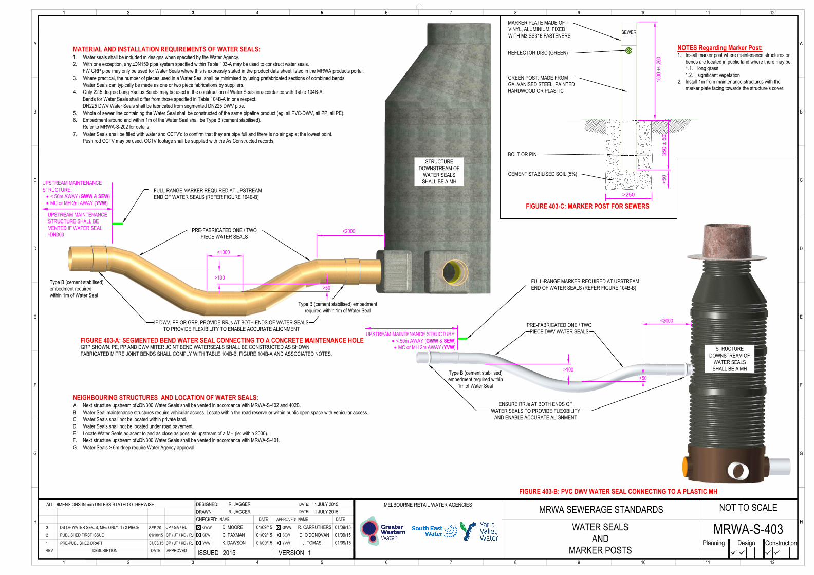
FIGURE 403-A: SEGMENTED BEND WATER SEAL CONNECTING TO A CONCRETE MAINTENANCE HOLE
FIGURE 403-B: PVC DWV WATER SEAL CONNECTING TO A PLASTIC MH
>50
>100
<2000
UPSTREAM MAINTENANCESTRUCTURE:· < 50m AWAY (GWW & SEW)· MC or MH 2m AWAY (YVW)
<2000
Type B (cement stabilised)embedment requiredwithin 1m of Water Seal
Type B (cement stabilised)embedment required within
1m of Water Seal
3 DS OF WATER SEALS, MHs ONLY. 1 / 2 PIECE CP / GA / RLSEP 20
STRUCTUREDOWNSTREAM OF
WATER SEALSSHALL BE A MH
FULL-RANGE MARKER REQUIRED AT UPSTREAMEND OF WATER SEALS (REFER FIGURE 104B-B)
FULL-RANGE MARKER REQUIRED AT UPSTREAMEND OF WATER SEALS (REFER FIGURE 104B-B)
UPSTREAM MAINTENANCESTRUCTURE SHALL BEVENTED IF WATER SEAL> DN300
>50>100
NOTES Regarding Marker Post:1. Install marker post where maintenance structures or
bends are located in public land where there may be:1.1. long grass1.2. significant vegetation
2. Install 1m from maintenance structures with themarker plate facing towards the structure's cover.
STRUCTUREDOWNSTREAM OF
WATER SEALSSHALL BE A MH
350 ± 50
>50
>250
FIGURE 403-C: MARKER POST FOR SEWERS
MARKER PLATE MADE OFVINYL, ALUMINIUM, FIXEDWITH M3 SS316 FASTENERS
GREEN POST. MADE FROMGALVANISED STEEL, PAINTEDHARDWOOD OR PLASTIC
REFLECTOR DISC (GREEN)
BOLT OR PIN
CEMENT STABILISED SOIL (5%)
1500
+/-
200
SEWER
MATERIAL AND INSTALLATION REQUIREMENTS OF WATER SEALS:1. Water seals shall be included in designs when specified by the Water Agency.2. With one exception, any > DN150 pipe system specified within Table 103-A may be used to construct water seals.
FW GRP pipe may only be used for Water Seals where this is expressly stated in the product data sheet listed in the MRWA products portal.3. Where practical, the number of pieces used in a Water Seal shall be minimised by using prefabricated sections of combined bends.
Water Seals can typically be made as one or two piece fabrications by suppliers.4. Only 22.5 degree Long Radius Bends may be used in the construction of Water Seals in accordance with Table 104B-A.
Bends for Water Seals shall differ from those specified in Table 104B-A in one respect.DN225 DWV Water Seals shall be fabricated from segmented DN225 DWV pipe.
5. Whole of sewer line containing the Water Seal shall be constructed of the same pipeline product (eg: all PVC-DWV, all PP, all PE).6. Embedment around and within 1m of the Water Seal shall be Type B (cement stabilised).
Refer to MRWA-S-202 for details.7. Water Seals shall be filled with water and CCTV'd to confirm that they are pipe full and there is no air gap at the lowest point.
Push rod CCTV may be used. CCTV footage shall be supplied with the As Constructed records.
NEIGHBOURING STRUCTURES AND LOCATION OF WATER SEALS:A. Next structure upstream of > DN300 Water Seals shall be vented in accordance with MRWA-S-402 and 402B.B. Water Seal maintenance structures require vehicular access. Locate within the road reserve or within public open space with vehicular access.C. Water Seals shall not be located within private land.D. Water Seals shall not be located under road pavement.E. Locate Water Seals adjacent to and as close as possible upstream of a MH (ie: within 2000).F. Next structure upstream of > DN300 Water Seals shall be vented in accordance with MRWA-S-401.G. Water Seals > 6m deep require Water Agency approval.
ENSURE RRJs AT BOTH ENDS OFWATER SEALS TO PROVIDE FLEXIBILITY
AND ENABLE ACCURATE ALIGNMENT
UPSTREAM MAINTENANCE STRUCTURE:· < 50m AWAY (GWW & SEW)· MC or MH 2m AWAY (YVW)
PRE-FABRICATED ONE / TWOPIECE WATER SEALS
IF DWV, PP OR GRP, PROVIDE RRJs AT BOTH ENDS OF WATER SEALSTO PROVIDE FLEXIBILITY TO ENABLE ACCURATE ALIGNMENT
PRE-FABRICATED ONE / TWOPIECE DWV WATER SEALS
Type B (cement stabilised) embedmentrequired within 1m of Water Seal
<1000
GRP SHOWN. PE, PP AND DWV MITER JOINT BEND WATERSEALS SHALL BE CONSTRUCTED AS SHOWN.FABRICATED MITRE JOINT BENDS SHALL COMPLY WITH TABLE 104B-B, FIGURE 104B-A AND ASSOCIATED NOTES.
MRWA SEWERAGE STANDARDS
VERSIONISSUED
MELBOURNE RETAIL WATER AGENCIESDATE:
DATE:
CHECKED:DRAWN:DESIGNED:
1 2 6 7 8 9 10 12113 4 5
H HGWW
SEW
YVW
DATENAME APPROVED:
GWW
SEW
YVW
DATENAME
APPROVEDDATEDESCRIPTIONREV
A
1 2 63 4 5
B
C
D
A
E
F
G
1 2 6 7 8 9 10 12113 5
A
B
C
D
E
F
G
H
Planning Design Construction
R. JAGGERR. JAGGER
D. MOOREC. PAXMANK. DAWSON
R. CARRUTHERS
J. TOMASI
1 JULY 20151 JULY 2015
PRE-PUBLISHED DRAFT1
2 PUBLISHED FIRST ISSUE 01/10/15 CP / JT / KD / RJ
2015 1CP / JT / KD / RJ
D. O'DONOVAN01/09/1501/09/1501/09/15
01/09/1501/09/1501/09/1501/03/15
ALL DIMENSIONS IN mm UNLESS STATED OTHERWISE NOT TO SCALE
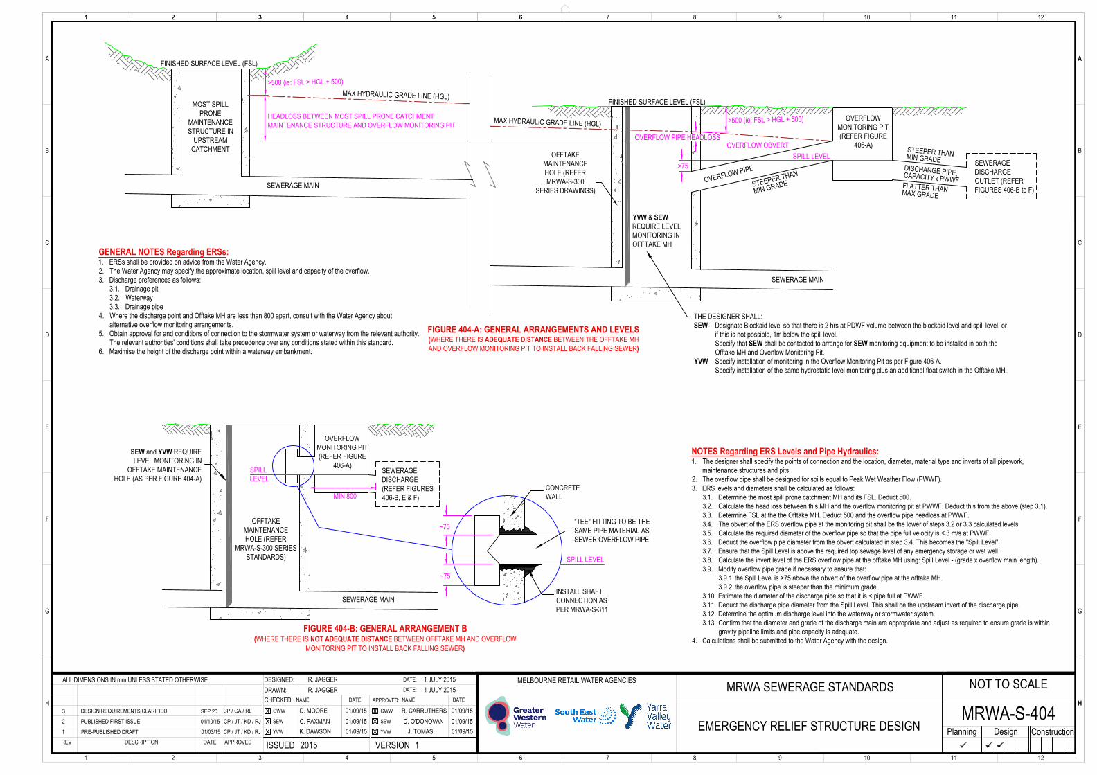
EMERGENCY RELIEF STRUCTURE DESIGNMRWA-S-404
SEWERAGE MAIN
>75
OVERFLOWMONITORING PIT(REFER FIGURE
406-A)OFFTAKE
MAINTENANCEHOLE (REFERMRWA-S-300
SERIES DRAWINGS)
SEWERAGEDISCHARGEOUTLET (REFERFIGURES 406-B to F)
FIGURE 404-A: GENERAL ARRANGEMENTS AND LEVELS(WHERE THERE IS ADEQUATE DISTANCE BETWEEN THE OFFTAKE MHAND OVERFLOW MONITORING PIT TO INSTALL BACK FALLING SEWER)
SEWERAGE MAIN
OVERFLOWMONITORING PIT(REFER FIGURE
406-A)SEWERAGEDISCHARGE(REFER FIGURES406-B, E & F)
OFFTAKEMAINTENANCEHOLE (REFER
MRWA-S-300 SERIESSTANDARDS)
FIGURE 404-B: GENERAL ARRANGEMENT B(WHERE THERE IS NOT ADEQUATE DISTANCE BETWEEN OFFTAKE MH AND OVERFLOW
MONITORING PIT TO INSTALL BACK FALLING SEWER)
SPILL LEVEL
GENERAL NOTES Regarding ERSs:1. ERSs shall be provided on advice from the Water Agency.2. The Water Agency may specify the approximate location, spill level and capacity of the overflow.3. Discharge preferences as follows:
3.1. Drainage pit3.2. Waterway3.3. Drainage pipe
4. Where the discharge point and Offtake MH are less than 800 apart, consult with the Water Agency aboutalternative overflow monitoring arrangements.
5. Obtain approval for and conditions of connection to the stormwater system or waterway from the relevant authority.The relevant authorities' conditions shall take precedence over any conditions stated within this standard.
6. Maximise the height of the discharge point within a waterway embankment.
MIN 800
SPILLLEVEL
CONCRETEWALL
~75
~75
INSTALL SHAFTCONNECTION ASPER MRWA-S-311
"TEE" FITTING TO BE THESAME PIPE MATERIAL ASSEWER OVERFLOW PIPE
STEEPER THANMIN GRADE
YVW & SEWREQUIRE LEVELMONITORING INOFFTAKE MH
SEW and YVW REQUIRELEVEL MONITORING IN
OFFTAKE MAINTENANCEHOLE (AS PER FIGURE 404-A)
3 DESIGN REQUIREMENTS CLARIFIED CP / GA / RLSEP 20
FLATTER THANMAX GRADESEWERAGE MAIN
MOST SPILLPRONE
MAINTENANCESTRUCTURE IN
UPSTREAMCATCHMENT
DISCHARGE PIPE,CAPACITY > PWWF
FINISHED SURFACE LEVEL (FSL)
MAX HYDRAULIC GRADE LINE (HGL) >500 (ie: FSL > HGL + 500)
OVERFLOW OBVERT
OVERFLOW PIPE
STEEPER THAN
MIN GRADE
MAX HYDRAULIC GRADE LINE (HGL)
>500 (ie: FSL > HGL + 500)
NOTES Regarding ERS Levels and Pipe Hydraulics:1. The designer shall specify the points of connection and the location, diameter, material type and inverts of all pipework,
maintenance structures and pits.2. The overflow pipe shall be designed for spills equal to Peak Wet Weather Flow (PWWF).3. ERS levels and diameters shall be calculated as follows:
3.1. Determine the most spill prone catchment MH and its FSL. Deduct 500.3.2. Calculate the head loss between this MH and the overflow monitoring pit at PWWF. Deduct this from the above (step 3.1).3.3. Determine FSL at the the Offtake MH. Deduct 500 and the overflow pipe headloss at PWWF.3.4. The obvert of the ERS overflow pipe at the monitoring pit shall be the lower of steps 3.2 or 3.3 calculated levels.3.5. Calculate the required diameter of the overflow pipe so that the pipe full velocity is < 3 m/s at PWWF.3.6. Deduct the overflow pipe diameter from the obvert calculated in step 3.4. This becomes the "Spill Level".3.7. Ensure that the Spill Level is above the required top sewage level of any emergency storage or wet well.3.8. Calculate the invert level of the ERS overflow pipe at the offtake MH using: Spill Level - (grade x overflow main length).3.9. Modify overflow pipe grade if necessary to ensure that:
3.9.1. the Spill Level is >75 above the obvert of the overflow pipe at the offtake MH.3.9.2. the overflow pipe is steeper than the minimum grade.
3.10. Estimate the diameter of the discharge pipe so that it is < pipe full at PWWF.3.11. Deduct the discharge pipe diameter from the Spill Level. This shall be the upstream invert of the discharge pipe.3.12. Determine the optimum discharge level into the waterway or stormwater system.3.13. Confirm that the diameter and grade of the discharge main are appropriate and adjust as required to ensure grade is within
gravity pipeline limits and pipe capacity is adequate.4. Calculations shall be submitted to the Water Agency with the design.
FINISHED SURFACE LEVEL (FSL)
SPILL LEVEL
OVERFLOW PIPE HEADLOSS
HEADLOSS BETWEEN MOST SPILL PRONE CATCHMENTMAINTENANCE STRUCTURE AND OVERFLOW MONITORING PIT
THE DESIGNER SHALL:SEW- Designate Blockaid level so that there is 2 hrs at PDWF volume between the blockaid level and spill level, or
if this is not possible, 1m below the spill level.Specify that SEW shall be contacted to arrange for SEW monitoring equipment to be installed in both theOfftake MH and Overflow Monitoring Pit.
YVW- Specify installation of monitoring in the Overflow Monitoring Pit as per Figure 406-A.Specify installation of the same hydrostatic level monitoring plus an additional float switch in the Offtake MH.
MORTAR
EROSIONPROTECTION(GEOTEXTILE ORROCK BEACHING)
HEADWALL,OVERSIZE ONESIZE > PIPE DN
BOTTOMSCREEN(GRID SPACING 100x30 NOM)
TOP SCREEN(GAL SL81 MESH)
100 GAP FOROVERFLOWFIGURE 406-B: SEWER OVERFLOW TO WATERWAY (SECTION)
FIGURE 406-D: END ELEVATION
FIGURE 406-C: SECTIONAL PLAN
FIX BRACKETS TO HEADWALL USINGMASONARY ANCHORS, REF 314-F to H
DRILL HOLES THROUGHWALL TO FASTEN BRACKETS
NOTES Regarding Figures 406-B, C & D:A. Screens and brackets to be hot dipped galvanised mild steel or stainless steel minimum grade 316.B. Fasteners and masonry anchors to be 316 stainless steel.
CEMENT STABILISE BACKFILL PIPEWHERE COVER IS LESS THAN 450
NON-RETURN FLAPVALVE TO MATCHSEWER OVERFLOW PIPE
-D
ROUGHEN PIPE AND SEALWITH COMPO, REFERTABLE 500-B
-CFSL
MRWA SEWERAGE STANDARDS
VERSIONISSUED
MELBOURNE RETAIL WATER AGENCIESDATE:
DATE:
CHECKED:DRAWN:DESIGNED:
1 2 6 7 8 9 10 12113 4 5
H HGWW
SEW
YVW
DATENAME APPROVED:
GWW
SEW
YVW
DATENAME
APPROVEDDATEDESCRIPTIONREV
A
1 2 63 4 5
B
C
D
A
E
F
G
1 2 6 7 8 9 10 12113 5
A
B
C
D
E
F
G
H
Planning Design Construction
R. JAGGERR. JAGGER
NOV 2019NOV 2019
PRE-PUBLISHED DRAFT. FROM PARENT 4041
2 PUBLISHED FIRST ISSUE. FROM PARENT 404 SEP 20 CP / GA / RL
2020 1CP / GA / WSNOV 19
ALL DIMENSIONS IN mm UNLESS STATED OTHERWISE
G. ANTHONSENC. PAXMANH. GERHARD
S. TRIKHA
R. LEOND. STEWART
SEP 20SEP 20SEP 20
SEP 20SEP 20SEP 20
NOT TO SCALE
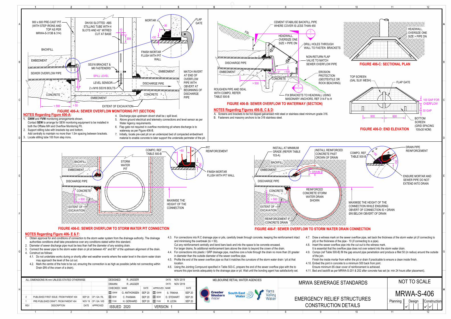
EMERGENCY RELIEF STRUCTURESCONSTRUCTION DETAILS
MRWA-S-406
INSTALL AT MINIMUMGRADE (REFER TABLE103-A)
EXTENT OFEXCAVATION
NOTES Regarding Figure 406- E & F:1. Obtain approval for and conditions of connection to the storm water system from the drainage authority. The drainage
authorities conditions shall take precedence over any conditions stated within this standard.2. Diameter of sewer discharge pipe must be less than half the diameter of any existing drain.3. Connect the sewer pipe to the storm water drain or pit at between 45° and 90° of the upstream alignment of the drain.4. Construct as follows:
4.1. Do not undertake works during or shortly after wet weather events where the water level in the storm water drainmay approach the level of the cut out.
4.2. Mark the centre of the hole to be cut, ensuring the connection is as high as possible (while not connecting withinDrain Ø/6 of the crown of a drain).
4.3. For connections into R.C drainage pipe or pits, carefully break through concrete, keeping the reinforcement intactand minimising the overbreak (to < 50).Cut any reinforcement centrally and bend bars back and into the space to be concrete encased.For larger drains, fix additional reinforcement bars above the drain to beyond the crown of the drain.
4.4. For connections into plastic / GRP drainage pipe, machine core a hole through the drain no more than 20 greaterin diameter than the outside diameter of the sewer overflow pipe.
4.5. Profile the end of the sewer overflow pipe so that it matches the curvature of the storm water drain / pit at thatlocation.
4.6. Using the Jointing Compound specified in Table 503-C, prepare the end of the sewer overflow pipe with the toensure this pipe bonds adequately to the drainage pipe or pit. Wait until the bonding agent has satisfactorily set.
4.7. Draw a witness mark on the sewer overflow pipe, set back the thickness of the storm water pit (if connecting topit) or the thickness of the pipe - 10 (if connecting to a pipe).
4.8. Insert the sewer overflow pipe into the cut out to the witness mark.It is essential that the overflow pipe does not over extend into the storm water drain.
4.9. Compo (ref Table 500-B) fill the gap around pipe penetration and produce a fillet 50 (in radius) around the outsideof the join.Finish the inside mortar from within the pit or drain if practicable to ensure a clean inside finish.
4.10. Embed the joint in concrete to a minimum 500 back from joint.Ensure minimum 65 clear cover of reinforcement is achieved.
4.11. Bed and backfill as per MRWA-S-201 & 202 after concrete has set (ie: min 24 hours after placement).
MAXIMISE THE HEIGHT OF THECONNECTION WHILE ENSURINGOBVERT OF CONNECTION IS > DRAINØ/6 BELOW OBVERT OF DRAIN
DISCHARGE PIPE
REINFORCEDCONCRETE STORM
WATER DRAINSHOWN
EMBEDMENT
CONCRETE
FLAP GATE
DISCHARGE PIPE
> 500
ENSURE MORTAR ANDSEWER PIPE DO NOTEXTEND INTO DRAIN
~50
FIGURE 406-F: SEWER OVERFLOW TO STORM WATER DRAIN CONNECTION
EMBEDMENT
EXTENT OFEXCAVATION
DISCHARGE PIPE
STORMWATER
PIT
CONCRETE
> 500
~50
FINISH MORTARFLUSH WITH PIT WALL
COMPO, REFTABLE 500-B
FIGURE 406-E: SEWER OVERFLOW TO STORM WATER PIT CONNECTION
BACKFILL BACKFILL
<50 <5
0
MAXIMISE THEHEIGHT OF THECONNECTION
NOTES Regarding Figure 406-A:1. GWW and YVW monitoring arrangements shown.
Contact SEW to arrange for SEW monitoring equipment to be installed inboth the Offtake MH and Overflow Monitoring Pit.
2. Support stilling tube with brackets top and bottom.Add centrally to maintain no more than 1.5m spacing between brackets.
3. Locate stilling tube 100 from step irons.
4. Discharge pipe upstream obvert shall be < spill level.5. Above ground electrical and telemetry connections and level sensor as per
Water Agency requirements.6. Flap gate not required in overflow monitoring pit where discharge is to
waterway as per Figure 406-B.7. Initially, locate pre-cast pit on an undersized bed of compacted embedment
material to enable concrete to later support the underside perimeter of the pit.
FIGURE 406-A: SEWER OVERFLOW MONITORING PIT (SECTION)
CONCRETE> 500
EMBEDMENT
30 GAP
600 600
PITREINFORCEMENT
REINFORCEMENT IFCONCRETE DRAIN
INSTALL REINFORCEDCONCRETE PASTCROWN OF DRAIN
> DRAIN Ø 6
DRAIN PIPEREINFORCEMENT
3°
HEADWALL,OVERSIZE ONESIZE > PIPE DN
~30
EMBEDMENT
EXTENT OF EXCAVATION
SEWER OVERFLOW PIPE
900 x 600 PRE-CAST PIT(WITH STEP IRONS AND
TOP AS PERMRWA-S-313B & 314)
CONCRETE
> 500
BACKFILL
SPILL LEVELEMBEDMENT
EMBEDMENTCONCRETE
FINISH MORTARFLUSH WITH PIT
WALL
<30
FLAPGATEDN100 SLOTTED ABS
STILLING TUBE WITH 4SLOTS AND 45° MITRED
CUT AT BASE
LEVEL SENSOR
SS316 BRACKET &M6 FASTENERS
DISCHARGE PIPE
> 50
200
10
2 x M16 SS316 BOLTS3°
MATCH INVERTAT END OFOVERFLOWPIPE WITHOBVERT ATBEGINNING OFDISCHARGEPIPE
~100
COMPO, REFTABLE 500-B