Embed Size (px)
Citation preview
Description.
LVX/R-00:0091 Rev C 01-04-25 © Ericsson. Commercial in confidence
BSS Description
Contents1 Introduction.................................................................................................................................3
2 Overview.....................................................................................................................................3
3 Radio Network Aspects ..............................................................................................................53.1 Radio Network Capacity............................................................................................................................53.2 Cost Effective Coverage ..........................................................................................................................153.3 Radio Network Quality ............................................................................................................................18
4 Installation, Operation and Maintenance ..................................................................................204.1 Low Life Cycle Costs...............................................................................................................................204.2 Network Rollout – Installation and Commissioning ................................................................................214.3 Radio Network Operation ........................................................................................................................214.4 Maintenance.............................................................................................................................................224.5 Radio Network Reconfiguration and Upgrade.........................................................................................244.6 Expanding RBS 200 with RBS 2000 .......................................................................................................25
5 Network Topology and Transmission Efficiency .....................................................................255.1 BSC Product family .................................................................................................................................255.2 Network Expansion..................................................................................................................................265.3 Transmission Efficiency...........................................................................................................................27
6 Data Communication ................................................................................................................296.1 Circuit Switched Services ........................................................................................................................296.2 Packet Switched Services.........................................................................................................................296.3 Short Message Services ...........................................................................................................................30
7 Positioning Services..................................................................................................................30
8 GSM – UMTS Handover and Reselection................................................................................31
9 BSC Platform............................................................................................................................319.1 AXE .........................................................................................................................................................329.2 Hardware Platform...................................................................................................................................32
10 System Characteristics ..............................................................................................................3410.1 BSC Capabilities and Capacity ................................................................................................................3410.2 Interfaces..................................................................................................................................................3510.3 Building Practice......................................................................................................................................3510.4 Environmental Conditions .......................................................................................................................36
11 Acronyms and Abbreviations....................................................................................................38
Description 2 (39)
© Ericsson. Commercial in confidence Rev C 01-04-25 LVX/R-00:0091
• Please note that this description is subject to change without notice. The descriptionincludes details on both basic and optional products. The description does notnecessarily correspond to any specific release or delivery time.
Description 3 (39)
LVX/R-00:0091 Rev C 01-04-25 © Ericsson. Commercial in confidence
1 IntroductionIn the Base Station System (BSS) development for GSM based systems, Ericsson hasidentified important areas where an operator can decrease costs and increase revenuessignificantly. These areas are:
• Radio network capacity and coverage
• Improvement of radio network quality
• Low life cycle costs
• Network roll-out speed
• Efficient transmission solutions
• Data communications.
This document intends to give an overview of the GSM-based system Base StationSystem (BSS) with respect to these areas from an operator point-of-view. In particular,the benefits of the Base Station Controller (BSC) are described. The BSC is undergoingcontinuous extensive development, and it is built upon experiences obtained worldwidefrom building and deploying Ericsson’s GSM mobile telephone systems.
Ericsson’s GSM-based systems (GSM 800, GSM 900, GSM 1800 and GSM 1900) areoperating in the 800, 900, 1800 and 1900 MHz bands. This description comprisesinformation on all these three systems.
2 OverviewThe Ericsson GSM-based system BSS is the world’s most powerful and flexible BaseStation System, capable of supporting more than 1,000 transceivers per BSC. Thismakes it outstanding in providing efficient radio network solutions. In another steptowards true global roaming the Ericsson BSC can handle all GSM bands (800/900/1800and 1900) residing in the same infrastructure. This significantly reduces theinfrastructure investments when introducing a multi-band system. It is particularlyeffective at providing services in areas where people from around the world oftenconverge, such as major international airports, congress centers etc.
The Ericsson BSC product family consists of a combined BSC/TRC and a remote BSC(without transcoders). The hardware platform is very economical with floor space. Thetranscoders are pooled, meaning that they can be allocated on demand – Full Rate, HalfRate, Enhanced Full Rate, AMR (Adaptive Multi Rate) Full Rate or AMR Half Rate.
Many radio network features are supported, which are important tools when increasingcapacity or coverage, or improving quality. Multi Layered Hierarchical Cell Structuresallows macro, micro, and pico cells to coexist in multi-layer and multi-band solutions.Adaptive use of cell resources is used to reach a maximum utilization of capacity. Someexamples are configuration of SDCCH, adaptive allocation of Half Rate and theadaptive allocation of General Packet Radio Services (GPRS) resources. Furthermore,tight frequency reuse methods to increase capacity is supported by features likeFrequency Hopping, Flexible MAIO Management, Discontinuous Transmission (DTX),Dynamic Power Control and AMR Full Rate. The Frequency Optimization Expertminimizes the need for frequency planning activities and makes sure that the most
Description 4 (39)
© Ericsson. Commercial in confidence Rev C 01-04-25 LVX/R-00:0091
suitable frequencies for a cell are used. These features make it possible to plan the radionetwork even tighter without decreasing quality.
Speech quality can be enhanced using Enhanced Full Rate or AMR speech codecs. Useof Half Rate channels as well as Multi Band functionality, providing more capacity, isalso supported.
High Speed Circuit Switched Data up to 58 kbit/s in four time slots is supported. Thismakes it possible for operators to offer new competitive data applications, which attractnew end-users.
GPRS in GSM enables the creation of new applications and will revolutionize mobiledata communications. GPRS will be able to coexist with the circuit switched serviceswithin the network, sharing frequencies and network equipment. With multislottransmission support for all coding schemes (CS-1 to CS-4) a raw data rate up to 160kbit/s for each TRX is possible. The early introduction of GPRS in a network is a clearimage enhancer for an operator, and consequently it is an opportunity to attract a largeamount of new end-users.
The introduction of EGPRS, that is EDGE packet switched data, will evolveGSM/GPRS systems into 3G networks, permitting a short time to market with 3Gservices. EGPRS is a simple add-on function to the existing GSM/GPRS networks,allowing significantly increased data throughput and capacity gains in comparison tousing GPRS only. Data rates up to 473.6 kbit/s will make it possible to provide advancedapplications requiring high data rates.
With Quality of Service (QoS) operators have the possibility to differentiate betweenusers by giving them different profiles in terms of throughput, prioritization andperceived quality over other users.
Installation is a simple and fast routine task with Radio Base Stations (RBS) from theRBS 2000 series, which comprises both outdoor and indoor versions, a Micro and a PicoRBS. Quick installation procedures result in a fast network rollout so that the operatorcan start earning money immediately. Furthermore, the RBSs have been made eveneasier to maintain, and special features are available, which enable remote operation anddownload of software. All these features are very important when it comes to keepinglife cycle costs low.
Transmission resource efficiency has been increased with the introduction of signalingconcentration and multiplexing on A-bis links, which can save signaling transmissionresources by up to 33 percent. The RBS 2000 series have built in support for multidropbut are also prepared for connection to the Ericsson Cellular Transmission System(DXX) Transport Network Solution, with which transmission resources are managed inan efficient way. The cross connect solutions allow plenty of network topologies to beapplied – star, cascade, ring, or mesh configurations. The remote BSC (withouttranscoders) gives lower transmission costs when building for coverage in rural areas.ET-155 gives new possibilities to optimize the transmission and lower the costs,introducing SDH transmission in the BSC.
For the operator to get the most out of the system, Ericsson has an extremely well built-out support organization, providing almost any kind of value-adding services – cellplanning, radio network investigation, operation and maintenance, expert assistance, and
Description 5 (39)
LVX/R-00:0091 Rev C 01-04-25 © Ericsson. Commercial in confidence
so forth. Moreover, Ericsson puts much effort on research and development to securethat the system stays competitive years after year.
All this together makes the Ericsson GSM-based system BSS the best choice for anoperator, whose goal is to obtain a high and steady revenue-providing system, and onethat will ensure safe operation and reliable development over the years to come.
3 Radio Network Aspects
3.1 Radio Network CapacityOperators work under different conditions, some having almost unlimited access to radiofrequency spectrum, some have to share it with many other operators on the market.Depending on access to spectrum, different approaches have to be made whenincreasing radio network capacity.
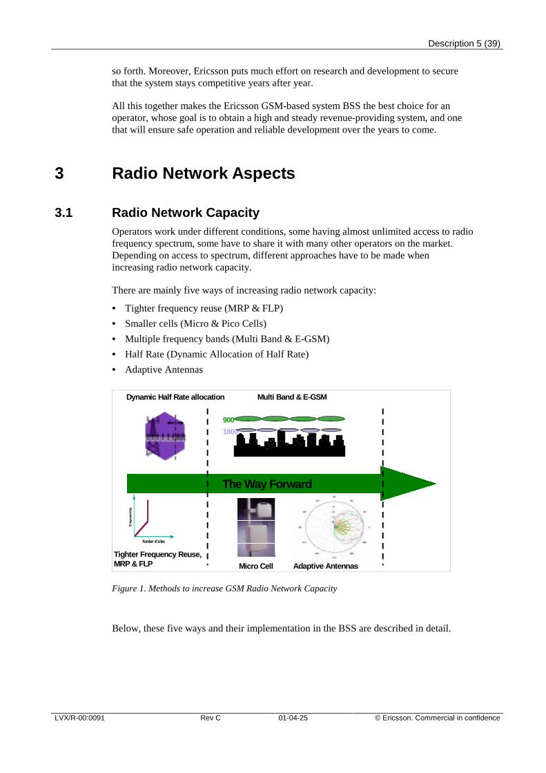
There are mainly five ways of increasing radio network capacity:
• Tighter frequency reuse (MRP & FLP)
• Smaller cells (Micro & Pico Cells)
• Multiple frequency bands (Multi Band & E-GSM)
• Half Rate (Dynamic Allocation of Half Rate)
• Adaptive Antennas
Tighter Frequency Reuse,MRP & FLP
Multi Band & E-GSM
900
1800
Pico-cells
Micro Cell Adaptive Antennas
The Way Forward
Dynamic Half Rate allocation
Figure 1. Methods to increase GSM Radio Network Capacity
Below, these five ways and their implementation in the BSS are described in detail.
Description 6 (39)
© Ericsson. Commercial in confidence Rev C 01-04-25 LVX/R-00:0091
Tighter Frequency ReuseRe-using frequencies tighter is an efficient way of increasing the utilization of frequencyspectrum without having to implement a great number of new costly sites. The mostimportant limiting factor for frequency reuse is the total interference in the systemmeasured as Carrier-to-Interference Ratio (C/I). C/I increases if the reuse distancedecreases. Many Ericsson radio network functions thus aim to allow a decrease in thereuse distance by reducing the total interference in the system – without jeopardizingcall continuity or speech quality.
Many operators are still using a 4/12 frequency reuse pattern. By deploying Base BandFrequency Hopping, a tighter reuse pattern, Multiple Reuse Pattern (MRP), can beimplemented. This will yield an increased number of frequencies and transceivers percell, resulting in a capacity increase. MRP implies that different reuse patterns are usedfor the different TRX’s in a cell. This method can be deployed on RBS’s with both filterand hybrid combiners.
By using synthesized frequency hopping, FLP (Fractional Load Planning) can beimplemented. This gives high capacity and easy frequency planning. FLP 1/1 and 1/3reuses are the two most common patterns used in FLP. This means that all cells in thenetwork hop on all for the operator available frequencies (1/1) or divided in three groupsthat each one of them hop on every third frequency (1/3). The exception is the BCCHfrequencies, which still have to be planned according to the traditional method of 4/12.FLP can be deployed on RBS’s with hybrid combiners.
Below, features supporting tighter frequency reuse are described.
Frequency Hopping
Urban areas are difficult to cell plan, as interference varies in an unpredictable mannerfrom place to place. Often, mobile stations are moving slowly, and it can happen that amobile station stays in a place for a longer time where interference is unacceptably high.
Frequency Hopping is the solution to this problem, providing an effect calledinterference diversity. By hopping to a new frequency for each burst, the lowinterference that some frequencies might have is spread among all ongoing connectionsin a cell, and the bit error rate is reduced to a level that coding and interleaving canhandle. Thus, Frequency Hopping mitigates fading dip effects. Frequency Hopping cantake place over the whole available bandwidth. The C/I improvements offered byfeatures like Dynamic Power Control and Discontinuous Transmission (DTX) will yieldmaximum benefits in conjunction with frequency hopping.
Flexible MAIO Management
Mobile Allocation Index Offset (MAIO) Management enables use of Fractional LoadPlanning (FLP) 1/1 and 1/3. MAIO is a parameter that determines when in time a certainfrequency allocated to a transceiver is used. In 1/1 when all cells have the same hoppingfrequencies it is vital to avoid that the same frequency is used simultaneously in twocells that impact on each other a lot. It is also important to prevent that adjacentfrequencies are used simultaneously, which is valid for 1/1 and some 1/3 reuse patterns.Flexible MAIO Management makes it possible to prevents this with the result that theoverall interference level in the network is minimized.
Description 7 (39)
LVX/R-00:0091 Rev C 01-04-25 © Ericsson. Commercial in confidence
Dynamic Power Control
Since the carrier signal for one mobile station is an interfering signal for another, onesolution is to use Dynamic Power Control. Then, the lowest possible output power isused while still maintaining a high quality connection. A connection, where the mobilestation is close to the BTS, the same output power is not needed as for a connection to amobile close to the cell border.
By taking both quality and signal strength into account in the Dynamic Power Controlalgorithm for circuit switched connections, the highest possible reductions in powerlevels can be achieved.
Discontinuous Transmission
During a normal two-party conversation, the participants alternate, so that each of themis silent for at least fifty percent of the time. By deploying the DiscontinuousTransmission (DTX) function on uplink and downlink, the transmitter can be switchedoff during speech pauses by means of the Voice Activity Detector. The algorithm is sofast, that it is able to turn off transmission even in pauses between words. This meansthat total radiated power decreases, and thus also interference. DTX is available both forspeech and for data transmission.
AMR Full Rate
The AMR speech codec in full rate channel provides a significant increase in speechquality robustness compared to EFR. Tests reveal that AMR can withstand interferencelevels that are approximately 6 dB higher than EFR for similar speech quality.Simulations show that this will correspond to more than a doubling of network capacityby applying tighter frequency reuse.
Frequency Optimization Expert
The Frequency Optimization Expert (FOX) that is implemented in the OSS and theBSC, ensures that correct frequency plans are implemented in order to achieve a highcapacity radio network with high speech quality and few dropped calls. FOXcomplements cell-planning tools by performing measurements of link interferencelevels. The measurement results are used as a basis for selecting the most suitablefrequencies for a cell. In this way, a tight frequency reuse pattern is achieved withoutaffecting the quality of the system. FOX can have three levels of automation: recordingmode, recommendation mode and automatic mode. In automatic mode, the systemautomatically, without manual intervention, implements changes to the neighboring cellslists in accordance with measurement results.
Another output from FOX is the Inter Cell Dependency Matrix (ICDM). The ICDM is ameasurement of how much different cells are interfering with each other. The ICDM is avery useful tool that has many uses. For example it can be imported into an external cell-planning tool and allow the operator to improve his frequency plan with his own tool. Itcan also be used to optimize the MAIO plan in networks with FLP 1/1 or 1/3 frequencyplans.
Description 8 (39)
© Ericsson. Commercial in confidence Rev C 01-04-25 LVX/R-00:0091
Dynamic Overlaid/Underlaid Subcells
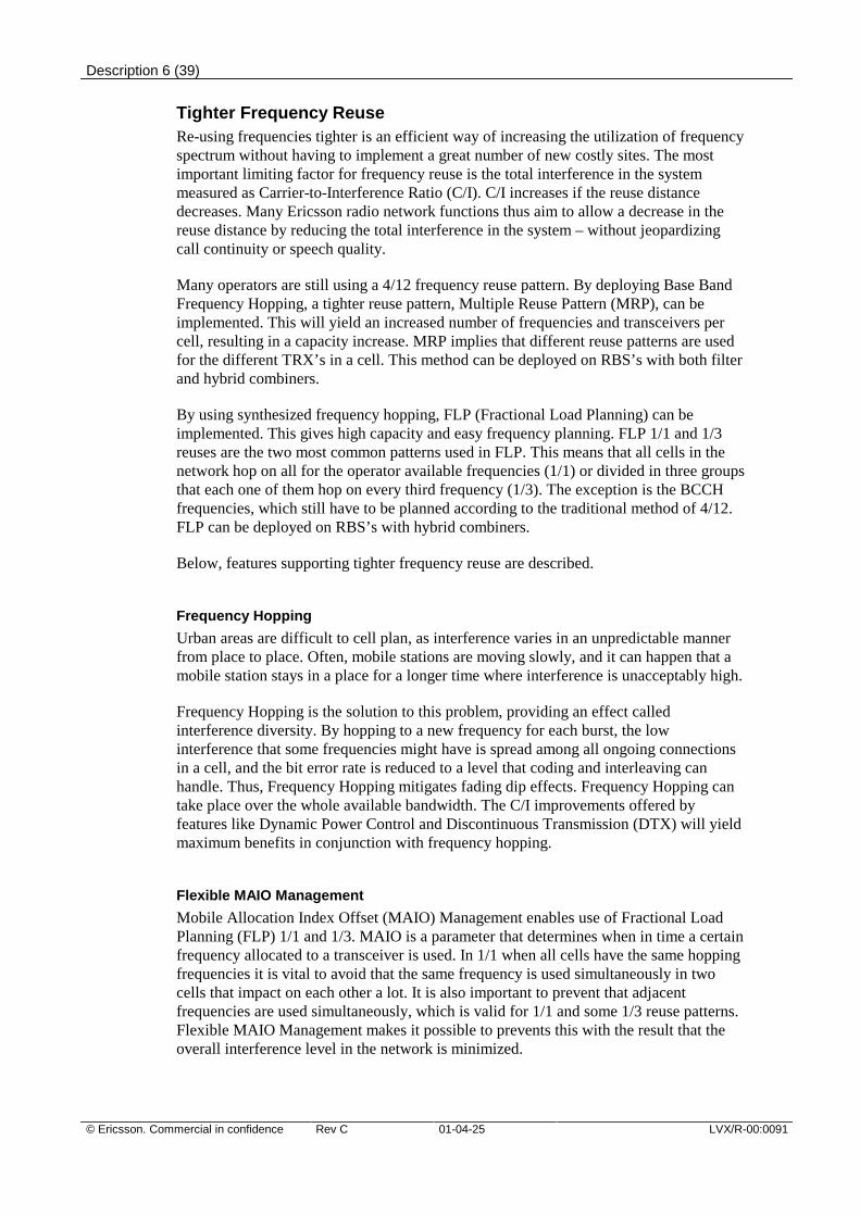
Another way to increase capacity without building new sites is to tighten the frequencyreuse by deploying the Dynamic Overlaid/Underlaid Subcells feature. The availablechannels in a cell are divided between an overlaid and an underlaid subcell.
By limiting the size of the overlaid subcell, a tighter frequency reuse can beimplemented in the overlaid subcells compared to the underlaid. Furthermore, theoverlaid subcell is used as a last resort when the traffic load in the underlaid subcellbecomes too high. This together with the fact that load peaks appear relatively locally inthe network makes it possible to use an extra tight frequency reuse pattern for theoverlaid subcells. (See Figure 2)
Figure 2. Overlaid/Underlaid Subcells.
BCCH in Overlaid Subcell
Normally in networks using synthesized frequency hopping the BCCH carrier is notfrequency hopping, which leaves the traffic channels on this carrier vulnerable tointerference. To ensure good speech quality it is necessary to have a sparse frequencyreuse for the BCCH frequencies.
By configuring the BCCH carrier in the overlaid subcell, the coverage limitingthresholds in Dynamic Overlaid/Underlaid Subcells can be used to ensure that terminalsusing traffic channels on the BCCH carrier is as close to the BTS as possible. Terminalsthat are close to the BTS are less sensitive to interference, and it is therefore possible tohave a tighter frequency reuse on the BCCH without jeopardizing speech quality.
Adaptive Configuration of SDCCH
The adaptive configuration of the SDCCH feature implies that the number of signalingchannels (SDCCH) and traffic channels (TCH) in a cell adapts to the current need. Timeslots are reconfigured from TCH to SDCCH and vice versa as the need varies. In thisway, the radio resources are always used in an optimal way.
Description 9 (39)
LVX/R-00:0091 Rev C 01-04-25 © Ericsson. Commercial in confidence
High Capacity Cells
High capacity cells are cells that have more than 12 TRX’s. With new functionality inRBS 2000 it is possible to build cells with 24 TRX’s or more. This can be used if thereare frequencies available. It is a cost efficient way to build out capacity where thecoverage already is sufficient. Some examples where it can be used are shopping malls,under ground systems and outdoor areas.
More Frequencies within the Existing Band
If the operator gets more bandwidth within the existing band, the operator only needs toadd the appropriate number of new transceivers and then do a new frequency plan to fitin the new frequencies.
Extended GSM Band
Ericsson's BSS supports the Extended GSM Band both in the BSC and in the RBS 2000family. The E-GSM band gives the operator access to up to 10 MHz extra GSMfrequencies in the 900 band. The frequencies can be used in the same cell as the other900 frequencies.
Smaller CellsThe traditional way to increase the capacity per area unit is to make macro cells smallerand smaller. At a certain macro cell site-to-site distance, interference begins to becrucial (below one kilometer). For operators having limited access to the frequencyspectrum, introducing micro cells then can prove very advantageous.
Micro and Pico Cells for Capacity
By introducing the micro cell concept, capacity can be increased many times –especially for operators having a limited frequency access.
Micro cells are outdoor cells, for which coverage is constrained in size by the relativelylow placement of the antennas – typically 5-10 meters above street level – and by usinglow output power. The micro cell radius is typically between 100 meters and onekilometer, covering the closest streets and nearby buildings.
Micro cells are suitable for adding capacity to hot spots like business districts, busystreets, and shopping areas. However, to handle very high traffic concentrations over alarger area like a city center, where it is not sufficient to make macro cells smaller,micro cells can be used.
Pico Cells are cells used inside buildings to provide extra capacity and coverage inshopping malls offices etc. Since the walls of the buildings limit the interference it ispossible to utilize the frequency spectrum very efficient and thereby reach very highcapacity inside the buildings.
Ericsson provides features and products that make installation, operation, andmaintenance of micro and indoor cells smooth and cost efficient. Some of these featuresand products are briefly described below.
Description 10 (39)
© Ericsson. Commercial in confidence Rev C 01-04-25 LVX/R-00:0091
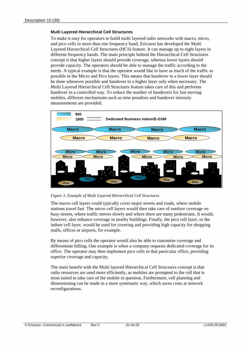
Multi Layered Hierarchical Cell Structures
To make it easy for operators to build multi layered radio networks with macro, micro,and pico cells in more than one frequency band, Ericsson has developed the MultiLayered Hierarchical Cell Structures (HCS) feature. It can manage up to eight layers indifferent frequency bands. The main principle behind the Hierarchical Cell Structuresconcept is that higher layers should provide coverage, whereas lower layers shouldprovide capacity. The operators should be able to manage the traffic according to theneeds. A typical example is that the operator would like to have as much of the traffic aspossible in the Micro and Pico layers. This means that handover to a lower layer shouldbe done whenever possible and handover to a higher layer only when necessary. TheMulti Layered Hierarchical Cell Structures feature takes care of this and performshandover in a controlled way. To reduce the number of handovers for fast movingmobiles, different mechanisms such as time penalties and handover intensitymeasurements are provided.
Pico
Macro MacroMacro Macro
Micro Micro Micro Micro Micro
Macro MacroMacro Macro
9001800 Dedicated Business indoor/E-GSM
PicoPico
PicoPico
Pico
Micro Micro MicroMicroMicro
Figure 3. Example of Multi Layered Hierarchical Cell Structures
The macro cell layers could typically cover major streets and roads, where mobilestations travel fast. The micro cell layers would then take care of outdoor coverage onbusy streets, where traffic moves slowly and where there are many pedestrians. It would,however, also enhance coverage in nearby buildings. Finally, the pico cell layer, or theindoor cell layer, would be used for covering and providing high capacity for shoppingmalls, offices or airports, for example.
By means of pico cells the operator would also be able to customize coverage anddifferentiate billing. One example is when a company requests dedicated coverage for itsoffice. The operator may then implement pico cells in that particular office, providingsuperior coverage and capacity.
The main benefit with the Multi layered Hierarchical Cell Structures concept is thatradio resources are used more efficiently, as mobiles are prompted to the cell that ismost suited to take care of the mobile in question. Furthermore, cell planning anddimensioning can be made in a more systematic way, which saves costs at networkreconfigurations.
Description 11 (39)
LVX/R-00:0091 Rev C 01-04-25 © Ericsson. Commercial in confidence
Neighboring Cell Optimization Expert
The Neighboring cell Optimization Expert (NOX) is a tool for identification andimplementation of optimized neighbor cell lists, which is essential for a good qualityradio network. NOX uses the neighbor cell measurements that mobile stations makeduring calls, complemented with handover statistics, to determine whether to add ordelete candidates in the neighbor cell lists. NOX can have three levels of automation:recording mode, recommendation mode and automatic mode. In automatic mode, thesystem automatically, without manual intervention, implements changes to theneighboring cells lists in accordance with measurement results.
Ericsson’s High Capacity BSC/TRC
Ericsson’s GSM-based system BSC/TRC is the most powerful GSM BSC/TRC on themarket, capable of handling over 500 cells and over 1,000 transceivers. Using only onehigh-capacity BSC/TRC instead of many low-capacity BSCs has many benefits,particularly when the Hierarchical Cell Structures concept is implemented, as all thehandovers between the layers can be managed by the same BSC. A high-capacityBSC/TRC reduces the number of inter-BSC handovers, which minimizes the load on theMSC/VLR and also decreases handover interrupt times.
Administration of new cells will be made centrally at one node only, instead of at manynodes. A large BSC will also minimize the number of times a cell has to be moved fromone BSC to another due to that a new BSC has to be introduced in the network. All thismakes the implementation of Hierarchical Cell Structures and changes in parametersquicker and safer, and the operator will not have to expect any loss of revenue due tosystem outages.
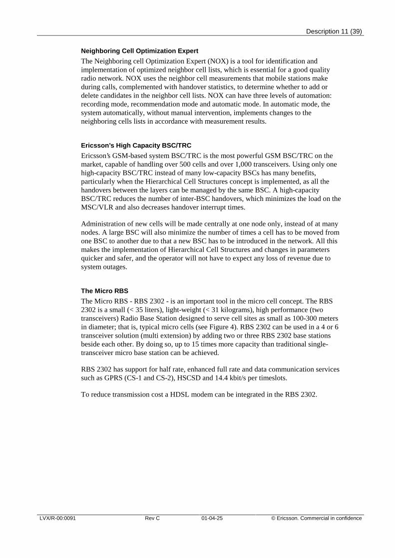
The Micro RBS
The Micro RBS - RBS 2302 - is an important tool in the micro cell concept. The RBS2302 is a small (< 35 liters), light-weight (< 31 kilograms), high performance (twotransceivers) Radio Base Station designed to serve cell sites as small as 100-300 metersin diameter; that is, typical micro cells (see Figure 4). RBS 2302 can be used in a 4 or 6transceiver solution (multi extension) by adding two or three RBS 2302 base stationsbeside each other. By doing so, up to 15 times more capacity than traditional single-transceiver micro base station can be achieved.
RBS 2302 has support for half rate, enhanced full rate and data communication servicessuch as GPRS (CS-1 and CS-2), HSCSD and 14.4 kbit/s per timeslots.
To reduce transmission cost a HDSL modem can be integrated in the RBS 2302.
Description 12 (39)
© Ericsson. Commercial in confidence Rev C 01-04-25 LVX/R-00:0091
Figure 4. The Micro RBS – RBS 2302.
One person can install the Micro RBS, and the small dimensions make it attractive forinstalling on poles or on walls. Landlords will also be more willing to give permits forsuch installations.
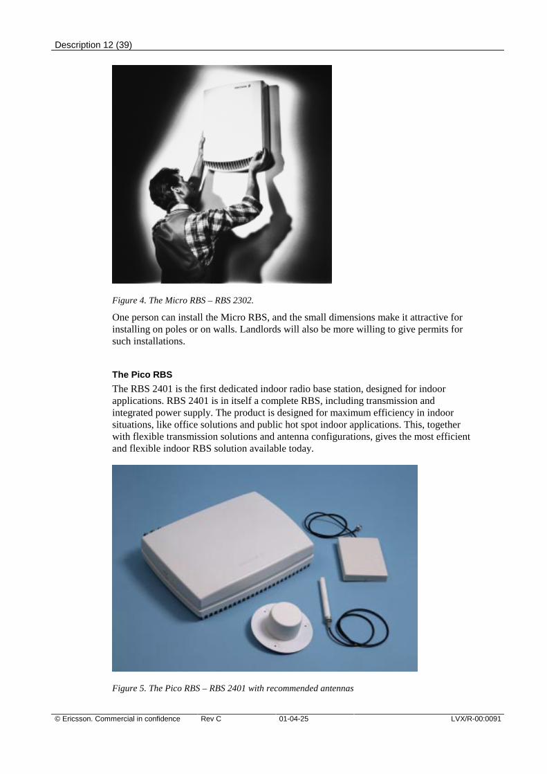
The Pico RBS
The RBS 2401 is the first dedicated indoor radio base station, designed for indoorapplications. RBS 2401 is in itself a complete RBS, including transmission andintegrated power supply. The product is designed for maximum efficiency in indoorsituations, like office solutions and public hot spot indoor applications. This, togetherwith flexible transmission solutions and antenna configurations, gives the most efficientand flexible indoor RBS solution available today.
Figure 5. The Pico RBS – RBS 2401 with recommended antennas
Description 13 (39)
LVX/R-00:0091 Rev C 01-04-25 © Ericsson. Commercial in confidence
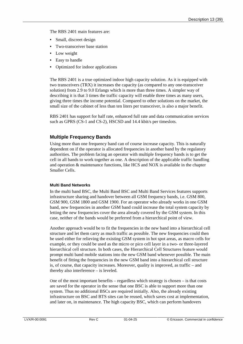
The RBS 2401 main features are:
• Small, discreet design
• Two-transceiver base station
• Low weight
• Easy to handle
• Optimized for indoor applications
The RBS 2401 is a true optimized indoor high capacity solution. As it is equipped withtwo transceivers (TRX) it increases the capacity (as compared to any one-transceiversolution) from 2.9 to 9.0 Erlangs which is more than three times. A simpler way ofdescribing it is that 3 times the traffic capacity will enable three times as many users,giving three times the income potential. Compared to other solutions on the market, thesmall size of the cabinet of less than ten liters per transceiver, is also a major benefit.
RBS 2401 has support for half rate, enhanced full rate and data communication servicessuch as GPRS (CS-1 and CS-2), HSCSD and 14.4 kbit/s per timeslots.
Multiple Frequency BandsUsing more than one frequency band can of course increase capacity. This is naturallydependent on if the operator is allocated frequencies in another band by the regulatoryauthorities. The problem facing an operator with multiple frequency bands is to get thecell in all bands to work together as one. A description of the applicable traffic handlingand operation & maintenance functions, like HCS and NOX is available in the chapterSmaller Cells.
Multi Band Networks
In the multi band BSC, the Multi Band BSC and Multi Band Services features supportsinfrastructure sharing and handover between all GSM frequency bands, i.e. GSM 800,GSM 900, GSM 1800 and GSM 1900. For an operator who already works in one GSMband, new frequencies in another GSM band could increase the total system capacity byletting the new frequencies cover the area already covered by the GSM system. In thiscase, neither of the bands would be preferred from a hierarchical point of view.
Another approach would be to fit the frequencies in the new band into a hierarchical cellstructure and let them carry as much traffic as possible. The new frequencies could thenbe used either for relieving the existing GSM system in hot spot areas, as macro cells forexample, or they could be used as the micro or pico cell layer in a two- or three-layeredhierarchical cell structure. In both cases, the Hierarchical Cell Structures feature wouldprompt multi band mobile stations into the new GSM band whenever possible. The mainbenefit of fitting the frequencies in the new GSM band into a hierarchical cell structureis, of course, that capacity increases. Moreover, quality is improved, as traffic – andthereby also interference – is leveled.
One of the most important benefits – regardless which strategy is chosen – is that costsare saved for the operator in the sense that one BSC is able to support more than onesystem. Thus no additional BSCs are required initially. Also, the already existinginfrastructure on BSC and BTS sites can be reused, which saves cost at implementation,and later on, in maintenance. The high capacity BSC, which can perform handovers
Description 14 (39)
© Ericsson. Commercial in confidence Rev C 01-04-25 LVX/R-00:0091
between the bands, is essential, because handovers are expected to be frequent in dualband networks. This implies that the load on the A interface transmission links and theMobile Switching Center (MSC) will not increase since most handovers will be handledwithin the BSCs.
The Ericsson BSC can actually work with all GSM bands (800/900/1800 and 1900)residing in the same infrastructure. This can be useful in areas where there is a need forcoexistence of all systems, for example in airports, convention centers, exhibition hallsetc. Co location of the 800/900/1800 and 1900 MHz radio base stations and theimplementation of the high capacity multi band BSC enables operators to maximize theuse of existing transmission networks.
Half Rate – Dynamic Half Rate AllocationThe BSC supports GSM Half Rate (HR) channels, which utilizes the available trafficchannels more efficiently than Full Rate (FR). HR is more spectrum efficient than FR,that is, the same amount of transceivers can handle double the amount of traffic channelsusing half rate. This means that traffic capacity is more than doubled, provided allmobile stations support Half Rate speech codecs. Also, HR channels require lesstransmission bandwidth than FR channels – 8 kbit/s instead of 16 kbit/s. HR can be setup for use in high traffic load situations and/or for certain categories of end-users. SinceHR slightly downgrades the speech quality, dynamic allocation of HR can be deployed.This means that HR is only used when necessary, when the alternative would becongestion in the cell. By introducing AMR Half Rate the speech quality in half ratechannels is significantly increased. This will make the use of half rate as a capacityincreasing option much more attractive.
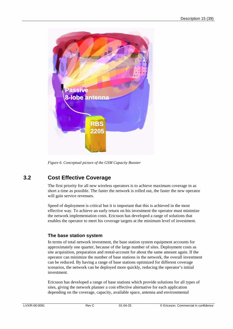
Adaptive AntennasEricsson’s adaptive antenna solution for GSM is called GSM Capacity Booster andconsists of a new radio base station, RBS 2205, and an array antenna. The adaptiveantenna splits the sector into 8 narrow lobes and will only transmit in the lobe where theactive mobile is located. On the up-link the base station will listen to all 8 lobessimultaneously and combine the 4 best of these. The concentration of the output powerin the narrow lobes in the downlink and the multi-branch diversity in the up-link reducesboth the distributed and received interference significantly. Typically the C/I values areincreased with 6 dB in the downlink and 10 dB in the up-link. This improved qualityenables capacity expansions not only in the adaptive antenna cell, but also in thesurrounding cells. Introduced in 10% of the cells, the GSM Capacity Booster enables atotal network capacity increase of up to 100%.
Description 15 (39)
LVX/R-00:0091 Rev C 01-04-25 © Ericsson. Commercial in confidence
Figure 6. Conceptual picture of the GSM Capacity Booster
3.2 Cost Effective CoverageThe first priority for all new wireless operators is to achieve maximum coverage in asshort a time as possible. The faster the network is rolled out, the faster the new operatorwill gain service revenues.
Speed of deployment is critical but it is important that this is achieved in the mosteffective way. To achieve an early return on his investment the operator must minimizethe network implementation costs. Ericsson has developed a range of solutions thatenables the operator to meet his coverage targets at the minimum level of investment.
The base station systemIn terms of total network investment, the base station system equipment accounts forapproximately one quarter, because of the large number of sites. Deployment costs assite acquisition, preparation and rental-account for about the same amount again. If theoperator can minimize the number of base stations in the network, the overall investmentcan be reduced. By having a range of base stations optimized for different coveragescenarios, the network can be deployed more quickly, reducing the operator’s initialinvestment.
Ericsson has developed a range of base stations which provide solutions for all types ofsites, giving the network planner a cost effective alternative for each applicationdepending on the coverage, capacity, available space, antenna and environmental
RRBBSS22220055
PPaassssiivvee88--lloobbee aanntteennnnaa
Description 16 (39)
© Ericsson. Commercial in confidence Rev C 01-04-25 LVX/R-00:0091
requirements. With a base station for every need, costs for site acquisition can bereduced and network deployment speed increased.
High capacity/standard siteAs the network matures there will be a need to increase capacity, particularly in urbanareas. It is therefore important that the base station system capacity can be easilyexpanded without increasing the number of antennas or the overall footprint. The highcapacity sites can be expanded to twelve transceiver units per cell using only one dualpolarized antenna.
Maximum range siteThis base station configuration provides the best link budget of all Ericsson GSM basestations, hence it will provide the most extended coverage. It is ideal for use in ruralareas, where capacity demand is low and it can also be deployed in urban areas toprovide good indoor coverage. The maximum range site will either reduce the number ofsites and/or increase the quality in the network. Since fewer sites are needed, it will alsoease the problem of site acquisition and speed up deployment.
The maximum range site can also be configured to provide road coverage. A specialantenna arrangement enables good coverage to be extended along the line of the roadrather than into the unpopulated surrounding areas. This solution will reduce the numberof sites required by half compared to a normal omni directional antenna arrangement,providing high capacity, good handover performance and high quality.
Microcellular and indoor sitesThe important requirements for microcellular and indoor sites are high capacity andsmall size. These sites can be easily and quickly deployed to provide focused capacityenhancement in traffic hotspots, and to improve indoor coverage and capacity.
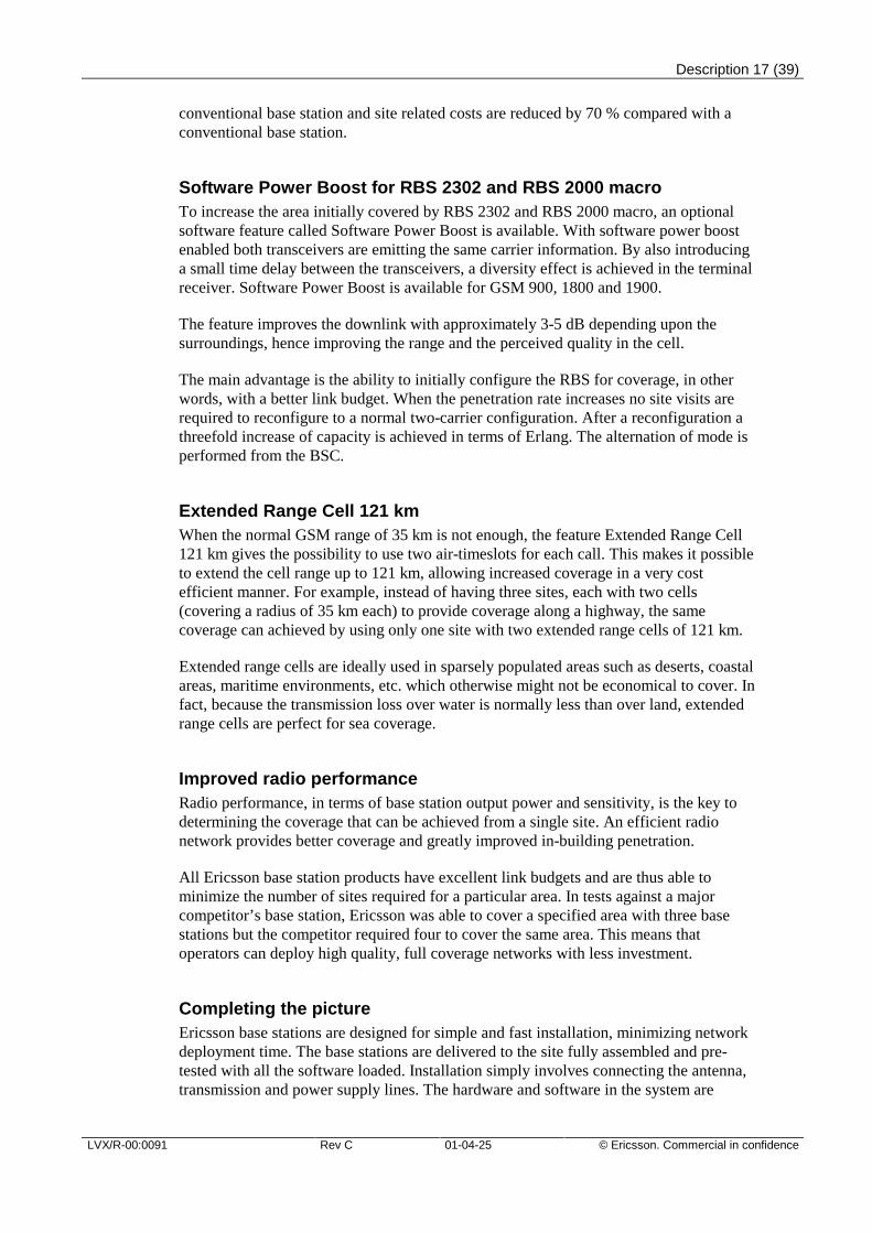
Maxite™Site acquisition is becoming a major issue so it is important that the base station systemand its associated antennas are as small and unobtrusive as possible. The small sizegives the additional benefit of making them easy and quick to install. To further increasethe flexibility of deployment of cell sites in sensitive or restricted areas, Ericsson hasdeveloped a complete modular site concept called Maxite™ which consist of a microbase station with an active antenna
With active antennas the power amplification is moved from the base station to theantenna itself. Not only does this reduce losses in the feeder cable, but also becausethere is no need for fans or air conditioning, the base station can be greatly reduced insize. The output power of the antenna is independent of feeder losses so powerefficiency is increased and power consumption reduced by around 65 %. Since the basestation has no moving parts, overall reliability is increased.
The power amplification in the antenna is distributed across a number of independentpower amplifiers so a failure in a single unit will only have a marginal effect on theantenna performance. Active antennas provide equal or better coverage than a
Description 17 (39)
LVX/R-00:0091 Rev C 01-04-25 © Ericsson. Commercial in confidence
conventional base station and site related costs are reduced by 70 % compared with aconventional base station.
Software Power Boost for RBS 2302 and RBS 2000 macroTo increase the area initially covered by RBS 2302 and RBS 2000 macro, an optionalsoftware feature called Software Power Boost is available. With software power boostenabled both transceivers are emitting the same carrier information. By also introducinga small time delay between the transceivers, a diversity effect is achieved in the terminalreceiver. Software Power Boost is available for GSM 900, 1800 and 1900.
The feature improves the downlink with approximately 3-5 dB depending upon thesurroundings, hence improving the range and the perceived quality in the cell.
The main advantage is the ability to initially configure the RBS for coverage, in otherwords, with a better link budget. When the penetration rate increases no site visits arerequired to reconfigure to a normal two-carrier configuration. After a reconfiguration athreefold increase of capacity is achieved in terms of Erlang. The alternation of mode isperformed from the BSC.
Extended Range Cell 121 kmWhen the normal GSM range of 35 km is not enough, the feature Extended Range Cell121 km gives the possibility to use two air-timeslots for each call. This makes it possibleto extend the cell range up to 121 km, allowing increased coverage in a very costefficient manner. For example, instead of having three sites, each with two cells(covering a radius of 35 km each) to provide coverage along a highway, the samecoverage can achieved by using only one site with two extended range cells of 121 km.
Extended range cells are ideally used in sparsely populated areas such as deserts, coastalareas, maritime environments, etc. which otherwise might not be economical to cover. Infact, because the transmission loss over water is normally less than over land, extendedrange cells are perfect for sea coverage.
Improved radio performanceRadio performance, in terms of base station output power and sensitivity, is the key todetermining the coverage that can be achieved from a single site. An efficient radionetwork provides better coverage and greatly improved in-building penetration.
All Ericsson base station products have excellent link budgets and are thus able tominimize the number of sites required for a particular area. In tests against a majorcompetitor’s base station, Ericsson was able to cover a specified area with three basestations but the competitor required four to cover the same area. This means thatoperators can deploy high quality, full coverage networks with less investment.
Completing the pictureEricsson base stations are designed for simple and fast installation, minimizing networkdeployment time. The base stations are delivered to the site fully assembled and pre-tested with all the software loaded. Installation simply involves connecting the antenna,transmission and power supply lines. The hardware and software in the system are
Description 18 (39)
© Ericsson. Commercial in confidence Rev C 01-04-25 LVX/R-00:0091
highly reliable and modular. With only a few replaceable units the number of requiredsite visits is reduced and thus operational costs is cut. Capacity extensions are carriedout quickly and easily by adding new transceiver units within the same cabinet.
Ericsson provides mobile operators with the capability to achieve the most cost-effectivecoverage through the use of flexible network and site solutions. This minimizes theoperator’s initial investment costs, reduces lifetime operational costs and ensures aspeedy return on investment.
3.3 Radio Network QualityGood quality in the mobile network is a clear key factor for success. The Ericsson BSShas a range of features that helps operators maintain high service availability alongsidehigh speech quality and service differentiation. Below, Ericsson's view on how radionetwork quality can be improved is presented.
Speech Quality EnhancersThe Enhanced Full Rate (EFR) feature gives, under good radio conditions, a speechquality which is comparable to or better than wire line telephony. The EFR feature isbased on the ETSI specified enhanced full rate speech codec and changes to thesignaling protocol, and does not require more bandwidth than Full Rate. Both RBS 200and RBS 2000 support EFR.
Support for the AMR speech codec type is the next step in speech quality for GSMsystem, incidentally the same AMR speech codec will also be used in UMTS systems. Inperfect radio conditions the speech quality is the same as for EFR, however AMR willdeliver significantly better speech quality in environments with heavy radio interference.AMR consist of a number of different speech codecs with different bit rate and channelcoding that is optimized for operation under different radio conditions. By continuouslyadapting which speech codec that is used according to the radio environment the bestpossible speech quality can always be achieved.
AMR is specified for use in both full rate and half rate channels.
Acoustic echoes are often created in the mobile terminals and these echoes are perceivedas bad speech quality. The Mobile Cross Talk Control (MCC) function built into thetranscoders can suppress these echoes and thereby enhance the quality.
The Ericsson patented algorithm in Speech Quality Supervision is used to measure thesubscriber quality, depending on the radio transmission. This will give the operator abetter view of potential improvement areas in the network. The operator will know ifpoor radio conditions affect the end-users or not.
Radio Network Support ProductsRadio network support increases in importance as the network grows and becomes moreand more complex. Ericsson has extensive experience in implementing, extending, andimproving mobile telephone systems. Ericsson can offer a range of methods, tools,services and guidelines for safe and fast radio network support. For example, the TEMS
Description 19 (39)
LVX/R-00:0091 Rev C 01-04-25 © Ericsson. Commercial in confidence
Cellplanner for advanced cell planning, the Radio Network Investigation service formature networks, cell-planning services, and complete turn-key systems.
Radio Link QualityTo improve radio link quality in difficult environments, the Idle Channel Measurementfeature and the Intracell Handover feature are available. The Idle Channel Measurementfeature continuously measures the interference level on unused idle channels, and usesthis information at channel allocation for setting up new calls on, or performinghandover to, less disturbed channels. The Intracell Handover feature carries outhandover to a channel in the same subcell when speech quality becomes too poor. Thisfeature can be used in frequency hopping systems, as well as in non-frequency hoppingsystems. The Neighbor cell Optimization Expert (NOX) helps the operator to find thecorrect set of neighbor cell relations in the network.
Besides the benefit of better radio link quality, these features facilitate cell planning inenvironments that are difficult to plan – like dense urban areas.
Leveling Fading Dips and Reducing InterferenceThe Frequency Hopping feature will ease the problem with slow moving mobiles gettingstuck in fading dips, by taking advantage of the coding and interleaving properties of theGSM air interface. This leads to improved speech and data transfer quality.
Reducing the Effects of HandoverThe Shorter Speech Interrupts at Handover feature makes speech interrupts at intra-BSChandover shorter. The average down link speech interrupt, at intra-BSC handover, isdecreased to approximately 80 milliseconds. The average up link speech interrupt isdecreased to 30 ms. The shorter speech interrupt is achieved by establishing two speechpaths through the BSC during the handover process – one to the serving channel, andone to the target channel. When the mobile station arrives on the new channel, thespeech path is already there.
Speech interruptions at inter-BSC handover are longer than those at intra-BSC handover.Ericsson's concept with a central, high-capacity BSC contributes to keeping speechinterruptions at handover short, as the amount of inter-BSC handovers are lower with alarge BSC than with a small one. This is especially useful when pursuing the micro cellnetwork strategy.
Ping-Pong handover is a phenomenon that occurs at cell borders. There, relative signalstrength differences and/or path loss differences between the serving cell and thepotential target cell for handover are small. By employing the hysteresis function of thechannel allocation algorithm, the mobile station is prompted to stay in the serving cell aslong as the handover candidate cell is not significantly better, thus eliminating Ping-Pong handover. The hysteresis function is a part of the locating algorithm.
Description 20 (39)
© Ericsson. Commercial in confidence Rev C 01-04-25 LVX/R-00:0091
4 Installation, Operation and Maintenance
4.1 Low Life Cycle CostsSeen over the economical lifetime of a mobile telephony system, costs for operating andmaintaining a mobile network exceed the initial investment costs – that is, costs forequipment, installation and commissioning of the system – by far. It is therefore mostimportant to keep operation and maintenance costs at a minimum. Minimizing cost ofoperation and maintenance is the same as human resource and physical equipment useefficiency.
Decreasing Operation and Maintenance CostKeeping costs for operation and maintenance low can be achieved by centralized BSShandling. It must be possible to supervise the network and to reconfigure equipment andcells remotely, without the need for visits to BTS sites. In addition, it is necessary thatthe BTS maintenance is easy and can be handled by first line maintenance personnel.
The Operation Support System
The Operations Support System (OSS) is a powerful tool for decreasing operationalcost. The Ericsson OSS applications for cellular network management cover suchimportant aspects as alarm surveillance and handling Ericsson network elements, radionetwork tuning and handling, performance and monitoring of vital radio networkoccurrences, and configuration of the various nodes within the cellular network.
The Ericsson OSS is based on the new Common Integration Framework (CIF). The OSSsolution can include management support for the GSM Radio Network, the CoreNetwork and also the UMTS Radio Access Network. The combination provides a cost-effective management solution. The OSS also acts as an efficient gateway towards othermanagement system.
Taking these facts into account, Ericsson strongly recommends that an OSS is includedin any BSS system in order to decrease network operation cost.
OSS can be connected to the BSC via X.25 or TCP/IP interface.
BSC Life Cycle Costs
The Ericsson BSC hardware platform reduces the site costs because the physical size iskept small as well as the power consumption is kept low. High In service performancetogether with few spare parts minimizes the site visits and the capital cost for spareparts. The installation time is short due to few number of cabinets and because thecabinets are pre-equipped and pre-tested at the factory. All BSC products are remotelycontrolled (except hardware changes) from the OSS.
RBS 2000 Life Cycle Costs
All RBS 2000 equipment handling - configuration, maintenance, and administration - iscontrolled by the BSC via the A-bis operation and maintenance interface or via theOperation and Maintenance Terminal (OMT). The RBS 2000 is highly modular in its
Description 21 (39)
LVX/R-00:0091 Rev C 01-04-25 © Ericsson. Commercial in confidence
design, both regarding hardware and software, comprising only a small number ofreplaceable units, which makes repair on site fast and easy. Furthermore, the productincludes test and supervision functions, which facilitate a distinct and rapid detection offaulty replaceable units. Software is downloaded from the BSC, and the softwaredownloading is executed as a background process, thus not disturbing ongoing traffic.Due to these characteristics RBS 2000 life cycle cost is kept to a minimum.
4.2 Network Rollout – Installation and CommissioningAs the network expands and subscriber density increases, the number of base stations ina network will increase drastically. This puts requirements on efficient processes for fastnetwork rollout and tools for network expansion and network tuning.
Due to Ericsson’s operation and maintenance design strategy, the RBS 2000 is extremelyeasy to handle, thus facilitating rapid roll out. If the site preparation is performedproperly, the installation and commissioning phase should normally take not more thanone hour.
It is possible for the operator to remove or add transceivers in a frequency hopping celland to change frequencies without releasing any ongoing calls in the cell. The cell willeven be able to offer service to new traffic.
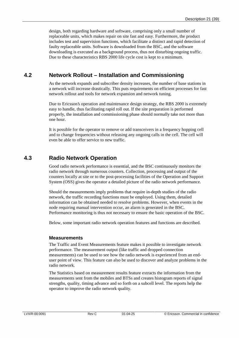
4.3 Radio Network OperationGood radio network performance is essential, and the BSC continuously monitors theradio network through numerous counters. Collection, processing and output of thecounters locally at site or to the post-processing facilities of the Operation and SupportSystem (OSS) gives the operator a detailed picture of the radio network performance.
Should the measurements imply problems that require in-depth studies of the radionetwork, the traffic recording functions must be employed. Using them, detailedinformation can be obtained needed to resolve problems. However, when events in thenode requiring manual intervention occur, an alarm is generated in the BSC.Performance monitoring is thus not necessary to ensure the basic operation of the BSC.
Below, some important radio network operation features and functions are described.
MeasurementsThe Traffic and Event Measurements feature makes it possible to investigate networkperformance. The measurement output (like traffic and dropped connectionmeasurements) can be used to see how the radio network is experienced from an end-user point of view. This feature can also be used to discover and analyze problems in theradio network.
The Statistics based on measurement results feature extracts the information from themeasurements sent from the mobiles and BTSs and creates histogram reports of signalstrengths, quality, timing advance and so forth on a subcell level. The reports help theoperator to improve the radio network quality.
Description 22 (39)
© Ericsson. Commercial in confidence Rev C 01-04-25 LVX/R-00:0091
The output can also be transferred to an OSS for advanced post-processing.
RecordingsThe Cell Traffic Recording feature provides an efficient tool for in-depth studies andradio path analysis. The feature can be used for observing live traffic and trafficbehavior in a cell based on statistical measurements. Events related to the traffichandling are recorded for a predefined set of cells; that is, messages sent and received onthe A and A-bis interfaces, respectively, and internal messages.
The Mobile Traffic Recording feature allows the operator to order recording for selectedmobile stations, which can be followed through the radio network. This allows theoperator to send test mobiles out in the radio network, if the performance of the networkneeds to be investigated in certain areas or for certain events. The recordings are startedfrom the MSC.
The Neighbor cell Optimization Expert feature helps the operator to set the correctneighboring cell relations in the network. The operator will get suggestions of the bestneighbor cells to be used. Detection of omitted neighboring cell relations will decreasethe dropped call ratio.
The Frequency Optimization Expert feature facilitates the frequency planning for theoperator by measuring the link interference levels. This leads to increased revenue anddecreased operation cost for frequency planning by providing information on the bestfrequencies to use when adding new sites or TRXs, thus also increasing quality in thenetwork.
The Real Time Event Data and Real Time Performance Monitoring features provides theoperator with feedback from radio network events in real time at the OSS node. This canbe used for detailed and accurate tuning of radio network parameters.
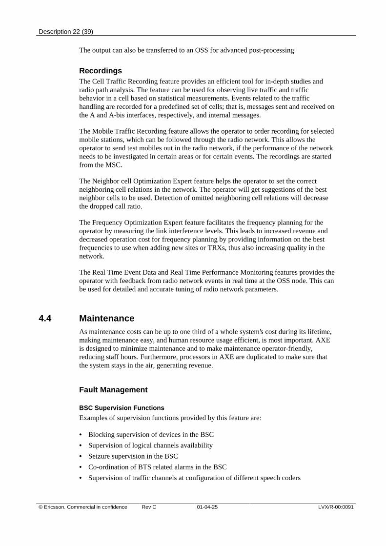
4.4 MaintenanceAs maintenance costs can be up to one third of a whole system’s cost during its lifetime,making maintenance easy, and human resource usage efficient, is most important. AXEis designed to minimize maintenance and to make maintenance operator-friendly,reducing staff hours. Furthermore, processors in AXE are duplicated to make sure thatthe system stays in the air, generating revenue.
Fault Management
BSC Supervision Functions
Examples of supervision functions provided by this feature are:
• Blocking supervision of devices in the BSC
• Supervision of logical channels availability
• Seizure supervision in the BSC
• Co-ordination of BTS related alarms in the BSC
• Supervision of traffic channels at configuration of different speech coders
Description 23 (39)
LVX/R-00:0091 Rev C 01-04-25 © Ericsson. Commercial in confidence
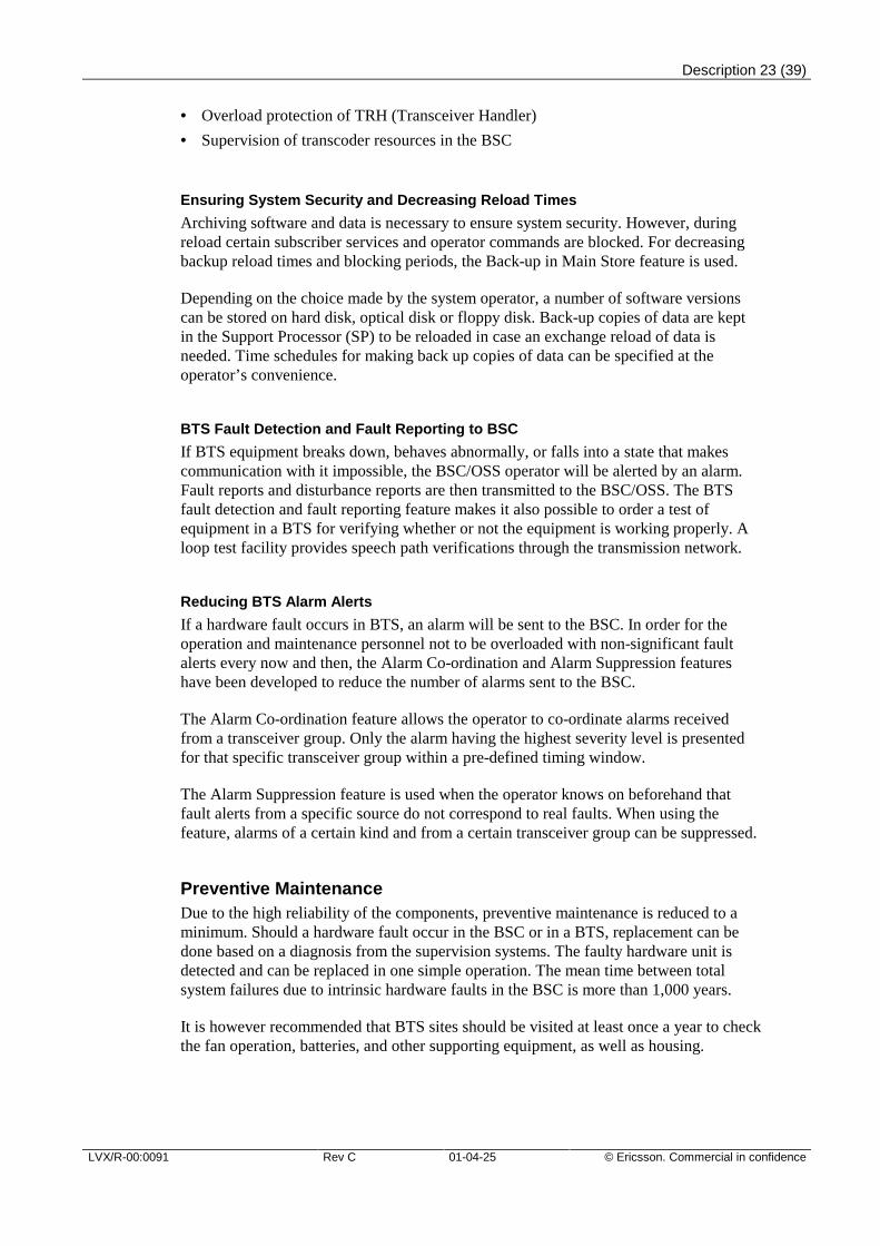
• Overload protection of TRH (Transceiver Handler)
• Supervision of transcoder resources in the BSC
Ensuring System Security and Decreasing Reload Times
Archiving software and data is necessary to ensure system security. However, duringreload certain subscriber services and operator commands are blocked. For decreasingbackup reload times and blocking periods, the Back-up in Main Store feature is used.
Depending on the choice made by the system operator, a number of software versionscan be stored on hard disk, optical disk or floppy disk. Back-up copies of data are keptin the Support Processor (SP) to be reloaded in case an exchange reload of data isneeded. Time schedules for making back up copies of data can be specified at theoperator’s convenience.
BTS Fault Detection and Fault Reporting to BSC
If BTS equipment breaks down, behaves abnormally, or falls into a state that makescommunication with it impossible, the BSC/OSS operator will be alerted by an alarm.Fault reports and disturbance reports are then transmitted to the BSC/OSS. The BTSfault detection and fault reporting feature makes it also possible to order a test ofequipment in a BTS for verifying whether or not the equipment is working properly. Aloop test facility provides speech path verifications through the transmission network.
Reducing BTS Alarm Alerts
If a hardware fault occurs in BTS, an alarm will be sent to the BSC. In order for theoperation and maintenance personnel not to be overloaded with non-significant faultalerts every now and then, the Alarm Co-ordination and Alarm Suppression featureshave been developed to reduce the number of alarms sent to the BSC.
The Alarm Co-ordination feature allows the operator to co-ordinate alarms receivedfrom a transceiver group. Only the alarm having the highest severity level is presentedfor that specific transceiver group within a pre-defined timing window.
The Alarm Suppression feature is used when the operator knows on beforehand thatfault alerts from a specific source do not correspond to real faults. When using thefeature, alarms of a certain kind and from a certain transceiver group can be suppressed.
Preventive MaintenanceDue to the high reliability of the components, preventive maintenance is reduced to aminimum. Should a hardware fault occur in the BSC or in a BTS, replacement can bedone based on a diagnosis from the supervision systems. The faulty hardware unit isdetected and can be replaced in one simple operation. The mean time between totalsystem failures due to intrinsic hardware faults in the BSC is more than 1,000 years.
It is however recommended that BTS sites should be visited at least once a year to checkthe fan operation, batteries, and other supporting equipment, as well as housing.
Description 24 (39)
© Ericsson. Commercial in confidence Rev C 01-04-25 LVX/R-00:0091
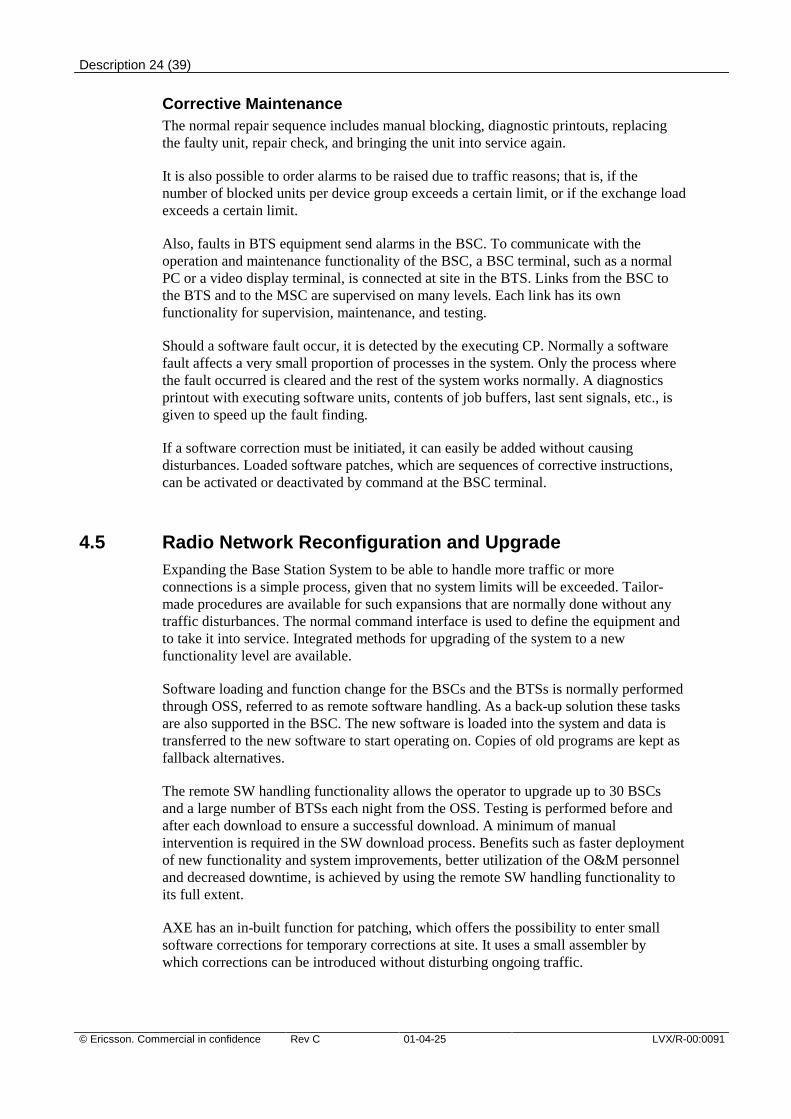
Corrective MaintenanceThe normal repair sequence includes manual blocking, diagnostic printouts, replacingthe faulty unit, repair check, and bringing the unit into service again.
It is also possible to order alarms to be raised due to traffic reasons; that is, if thenumber of blocked units per device group exceeds a certain limit, or if the exchange loadexceeds a certain limit.
Also, faults in BTS equipment send alarms in the BSC. To communicate with theoperation and maintenance functionality of the BSC, a BSC terminal, such as a normalPC or a video display terminal, is connected at site in the BTS. Links from the BSC tothe BTS and to the MSC are supervised on many levels. Each link has its ownfunctionality for supervision, maintenance, and testing.
Should a software fault occur, it is detected by the executing CP. Normally a softwarefault affects a very small proportion of processes in the system. Only the process wherethe fault occurred is cleared and the rest of the system works normally. A diagnosticsprintout with executing software units, contents of job buffers, last sent signals, etc., isgiven to speed up the fault finding.
If a software correction must be initiated, it can easily be added without causingdisturbances. Loaded software patches, which are sequences of corrective instructions,can be activated or deactivated by command at the BSC terminal.
4.5 Radio Network Reconfiguration and UpgradeExpanding the Base Station System to be able to handle more traffic or moreconnections is a simple process, given that no system limits will be exceeded. Tailor-made procedures are available for such expansions that are normally done without anytraffic disturbances. The normal command interface is used to define the equipment andto take it into service. Integrated methods for upgrading of the system to a newfunctionality level are available.
Software loading and function change for the BSCs and the BTSs is normally performedthrough OSS, referred to as remote software handling. As a back-up solution these tasksare also supported in the BSC. The new software is loaded into the system and data istransferred to the new software to start operating on. Copies of old programs are kept asfallback alternatives.
The remote SW handling functionality allows the operator to upgrade up to 30 BSCsand a large number of BTSs each night from the OSS. Testing is performed before andafter each download to ensure a successful download. A minimum of manualintervention is required in the SW download process. Benefits such as faster deploymentof new functionality and system improvements, better utilization of the O&M personneland decreased downtime, is achieved by using the remote SW handling functionality toits full extent.
AXE has an in-built function for patching, which offers the possibility to enter smallsoftware corrections for temporary corrections at site. It uses a small assembler bywhich corrections can be introduced without disturbing ongoing traffic.
Description 25 (39)
LVX/R-00:0091 Rev C 01-04-25 © Ericsson. Commercial in confidence
4.6 Expanding RBS 200 with RBS 2000For operators that have been investing in the previous generation of base station RBS200 a new opportunity is available. The investments of RBS 200 can be protected sinceit is possible to expand RBS 200 cells with RBS 2000 in the same cell. This means thatno costly relocations of RBS 200 or replacements are needed. This solution will makethe cell future proof. One example is EDGE, which is supported by RBS 2000 and notRBS 200.
5 Network Topology and TransmissionEfficiencyThe Ericsson BSS aims at reducing the total cost for a network, that is, transmissioncosts, operation and maintenance costs and investment costs. The BSC product familysupports cost effective network topologies for both metropolitan and rural areas that canmigrate from a coverage solution to a high capacity solution.
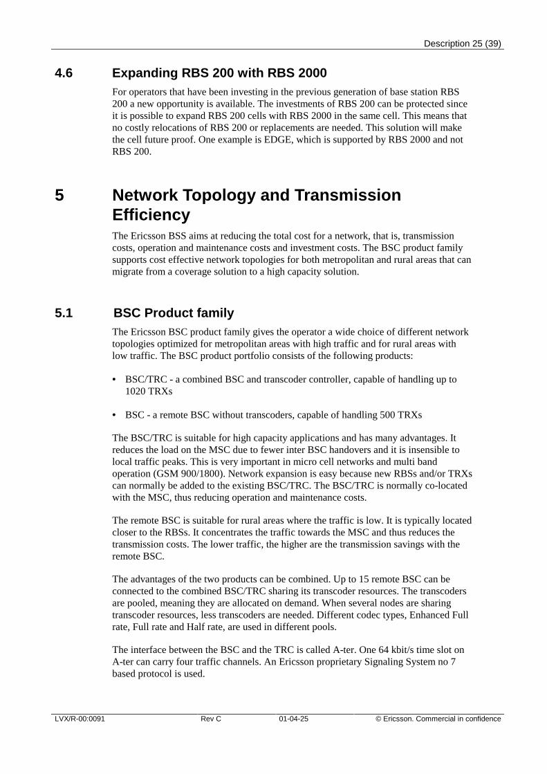
5.1 BSC Product familyThe Ericsson BSC product family gives the operator a wide choice of different networktopologies optimized for metropolitan areas with high traffic and for rural areas withlow traffic. The BSC product portfolio consists of the following products:
• BSC/TRC - a combined BSC and transcoder controller, capable of handling up to1020 TRXs
• BSC - a remote BSC without transcoders, capable of handling 500 TRXs
The BSC/TRC is suitable for high capacity applications and has many advantages. Itreduces the load on the MSC due to fewer inter BSC handovers and it is insensible tolocal traffic peaks. This is very important in micro cell networks and multi bandoperation (GSM 900/1800). Network expansion is easy because new RBSs and/or TRXscan normally be added to the existing BSC/TRC. The BSC/TRC is normally co-locatedwith the MSC, thus reducing operation and maintenance costs.
The remote BSC is suitable for rural areas where the traffic is low. It is typically locatedcloser to the RBSs. It concentrates the traffic towards the MSC and thus reduces thetransmission costs. The lower traffic, the higher are the transmission savings with theremote BSC.
The advantages of the two products can be combined. Up to 15 remote BSC can beconnected to the combined BSC/TRC sharing its transcoder resources. The transcodersare pooled, meaning they are allocated on demand. When several nodes are sharingtranscoder resources, less transcoders are needed. Different codec types, Enhanced Fullrate, Full rate and Half rate, are used in different pools.
The interface between the BSC and the TRC is called A-ter. One 64 kbit/s time slot onA-ter can carry four traffic channels. An Ericsson proprietary Signaling System no 7based protocol is used.
Description 26 (39)
© Ericsson. Commercial in confidence Rev C 01-04-25 LVX/R-00:0091
Figure 7. Supported Network Topologies with the Ericsson BSC Product Family
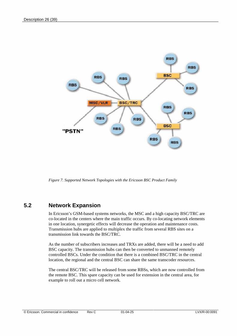
5.2 Network ExpansionIn Ericsson’s GSM-based systems networks, the MSC and a high capacity BSC/TRC areco-located in the centers where the main traffic occurs. By co-locating network elementsin one location, synergetic effects will decrease the operation and maintenance costs.Transmission hubs are applied to multiplex the traffic from several RBS sites on atransmission link towards the BSC/TRC.
As the number of subscribers increases and TRXs are added, there will be a need to addBSC capacity. The transmission hubs can then be converted to unmanned remotelycontrolled BSCs. Under the condition that there is a combined BSC/TRC in the centrallocation, the regional and the central BSC can share the same transcoder resources.
The central BSC/TRC will be released from some RBSs, which are now controlled fromthe remote BSC. This spare capacity can be used for extension in the central area, forexample to roll out a micro cell network.
Description 27 (39)
LVX/R-00:0091 Rev C 01-04-25 © Ericsson. Commercial in confidence
Figure 8. Cost Efficient Network Expansion with the BSC.
In this way, network expansion can be performed without re-arranging the radio andtransmission network and without disturbing the ongoing traffic.
When the traffic increases even further, the remote BSC can be converted to a highcapacity BSC/TRC.
5.3 Transmission EfficiencyTransmission efficiency on the A-bis interface is achieved by using the LAPDConcentration or LAPD Multiplexing features. The remote BSC gives lowertransmission costs when building for coverage in rural areas.
LAPD ConcentrationLAPD concentration is achieved by letting up to four TRXs share one 64 kbit/s time slotfor signaling, instead of using one time slot each. LAPD Concentration thus givesapproximately 25 percent savings in transmission. This feature is especially useful inhigh-traffic areas for RBS sites with 3 TRXs/cell or more. LAPD Concentration isavailable both for RBS 200 and RBS 2000.
LAPD MultiplexingThe LAPD Multiplexing feature offers an alternative way to decrease transmissioncosts. Traffic channels and LAPD signaling links are multiplexed into the same 64 kbit/stime slot, instead of using a separate time slot for signaling. This feature is mostefficient for small RBS sites with one or two TRXs/cell. Only two 64 kbit/s time slotsper TRX are needed, which implies 33 percent savings in transmission. LAPDMultiplexing is available for RBS 2000.
Description 28 (39)
© Ericsson. Commercial in confidence Rev C 01-04-25 LVX/R-00:0091
ET-155ET-155 gives direct access to SDH STM-1 from the BSC. One ET-155 can be usedsimultaneously towards the A, A-bis and A-ter interfaces. The ET-155 can be usedsimultaneously together with E1 and T1 transmission. One ET-155 replaces 63 E1 2Mbit ETs thus two optical cables replace 63 cables. The ET155 concept supportsprotection switching which means that if the ET155 function HW unit goes down thesystem automatically switches over to a redundant ET155 HW unit. This means that atleast two ET155 function HW units are required within a BSC or BSC/TRC node. Thisgives a more efficient transmission, increases reliability, enhances fault handling andshortens the installation time considerably.
Remote BSCThe remote BSC gives lower transmission costs when building for coverage in ruralareas because it concentrates the traffic towards the MSC. The transmission saving isdependent on the traffic volume and is highest when the traffic is low. This is becausethe A-ter interface dimensioning is based on the traffic volume while the A-bis interfaceis dimensioned according to the number of transceivers.
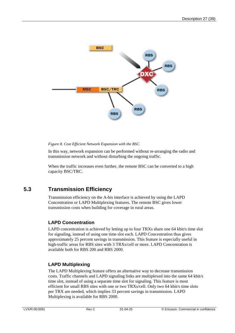
Interfaces over SatelliteInterfaces over satellite gives the operator the possibility to cover remote and isolatedareas. These areas are too expensive to reach with traditional transmission solutions.Also temporary transmission solutions at sport events etc. can quickly be provided withthis feature. Satellite connections are supported over A, A-bis and A-ter interfaces.
Figure 9. Example of how to use Interfaces over satellite.
BTS network topologiesTransceiver Remote Interfaces (TRIs) are used to cascade RBS 200s. BSS features suchas Multidrop at RBS 2000 and Long Haul allow cascading of several RBS 2000swithout having to use additional transmission equipment. The BSA or the DXXtransport module can be used to support more advanced configurations for example ringand remote star and to provide redundancy. The operator is also free to select any othervendor’s transport module.
Description 29 (39)
LVX/R-00:0091 Rev C 01-04-25 © Ericsson. Commercial in confidence
6 Data CommunicationAs the demand for advanced wireless data and video applications grows, userexpectations for speed and quality will follow. Ericsson is offering powerful datacomsolutions for operators wanting to be in the frontline of offering high-end datacommunication in GSM. The Ericsson BSS supports both packet switched services aswell as circuit switched services. Circuit switched services and High Speed CircuitSwitched Data offer data rates up to 57.6 kbit/s. Packet switched services such as GPRSoffer data rates up to 160 kbit/s, while EGPRS enables data rates up to 474 kbit/s,exceeding 384 kbit/s that is the ITU definition of 3G.
6.1 Circuit Switched Services
Single Slot Data CallsAlmost all data rates according to GSM are supported in the BSS. All transparent dataservices with the following data transmission rates are supported: 14.4 kbit/s, 9.6 kbit/s,4.8 kbit/s, 2.4 kbit/s, 1.2 kbit/s, 600 bit/s, 1200/75 bit/s. For non-transparent dataservices, the data rates 13 kbit/s and 9.6 kbit/s are supported.
High Speed Circuit Switched DataData communication rates up to 57.6 kbit/s are supported by the High Speed CircuitSwitched Data feature. This is achieved by using up to four time slots for oneconnection. Both transparent and non-transparent connections are supported. Thetransmission rate can vary during a non-transparent call, either depending on userrequest or network capacity available.
High Speed Circuit Switched Data gives the operator the possibility to offer newcompetitive data applications, which attract new end-users, and gives the operator animproved image as a high tech or business communication operator.
6.2 Packet Switched Services
GPRSGPRS (General Packet Radio Services) introduces packet data transmission all the wayout to the mobile subscriber, enabling the subscribers to easily use data services such ase-mail, sporadic internet and intranet browsing and so on. GPRS also opens up a newarea to the operators, where they together with third party suppliers can developapplications strategically for their business purposes. GPRS is designed to work withinthe existing GSM infrastructure with additional packet switching nodes, which meansthat GPRS coverage can be introduced in a quick and easy way. Several users will sharea GPRS radio resource, thus giving better channel utilization. The end-user may remainconnected to the accessed data network as long as desired, but will only be charged forthe data volume transmitted and/or received. This packet mode technique uses multi-slot technology together with support for all coding schemes (CS-1 to CS-4) to increasethe data rates up to 160 kbit/s. In the first phase PTP (Point-To-Point) transmission willbe supported, later PTM (Point to Multipoint) transmissions will be introduced.
Description 30 (39)
© Ericsson. Commercial in confidence Rev C 01-04-25 LVX/R-00:0091
EGPRSEnhanced GPRS (EGPRS) is combining GPRS functionality with the new standardizedpacket switched EDGE functionality. EDGE introduces a new high level modulation, aswell as protocol enhancements for transmitting packets over the radio. The use of thenew modulation and the protocol enhancements, result in dramatically increasedthroughput and capacity gains enabling 3G services in existing GSM/GPRS networks.
EGPRS is a simple add-on function to existing GSM/GPRS networks, allowing a fasttime to market with 3G services. With EGPRS in the network end-users will experiencesignificantly increased data throughput in comparison to using GPRS only. Capacitygains and new services enabled by EGPRS will generate new revenues for the operator.
With reservation of up to eight timeslots per user together with the higher codingschemes introduced data rates up to 474 kbit/s can be achieved in existing GSM/GPRSnetworks.
Quality of Service (QoS)QoS has been harmonized and standardized for both GSM and UMTS. With theintroduction of QoS in GSM Networks GPRS/EGPRS users will perceive a higherquality of the radio bearer service. Quality of Service (QoS) allows the operator todifferentiate between users by giving them different profiles in terms of throughput,prioritization and perceived quality over other users.
6.3 Short Message ServicesThere are two types of short message services, SMS Point-to-Point and SMS – CellBroadcast. The difference is that an SMS Point-to-Point message is sent or received byone mobile terminal, while SMS – Cell Broadcast messages are sent to all mobiles in aspecific area.
SMS Point-to-PointSMS Point-to-Point makes it possible to send a message consisting of a maximum of160 alphanumeric characters to or from a mobile station.
SMS – Cell BroadcastAn SMS – Cell Broadcast message, is a message consisting of a maximum of 160characters from European, African and Asian languages. The message can be broadcastto all mobile stations within a certain geographical area. Examples of applications couldbe traffic congestion warnings, reports on accidents, local advertisements, and evencharging information.
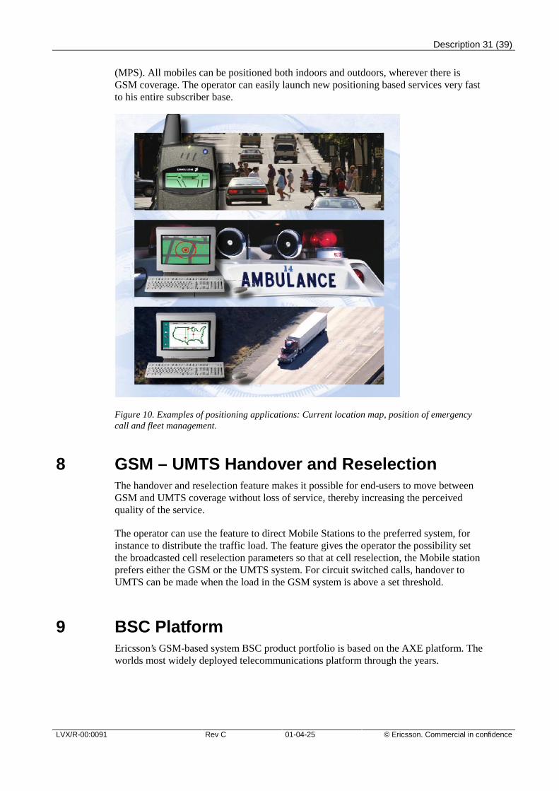
7 Positioning ServicesWith the positioning service a large number of applications are possible to launch. Someexamples are fleet management, positioning of emergency calls and access to localizedservices. The BSC provides positioning information to the Mobile Positioning Center
Description 31 (39)
LVX/R-00:0091 Rev C 01-04-25 © Ericsson. Commercial in confidence
(MPS). All mobiles can be positioned both indoors and outdoors, wherever there isGSM coverage. The operator can easily launch new positioning based services very fastto his entire subscriber base.
Figure 10. Examples of positioning applications: Current location map, position of emergencycall and fleet management.
8 GSM – UMTS Handover and ReselectionThe handover and reselection feature makes it possible for end-users to move betweenGSM and UMTS coverage without loss of service, thereby increasing the perceivedquality of the service.
The operator can use the feature to direct Mobile Stations to the preferred system, forinstance to distribute the traffic load. The feature gives the operator the possibility setthe broadcasted cell reselection parameters so that at cell reselection, the Mobile stationprefers either the GSM or the UMTS system. For circuit switched calls, handover toUMTS can be made when the load in the GSM system is above a set threshold.
9 BSC PlatformEricsson’s GSM-based system BSC product portfolio is based on the AXE platform. Theworlds most widely deployed telecommunications platform through the years.
Description 32 (39)
© Ericsson. Commercial in confidence Rev C 01-04-25 LVX/R-00:0091
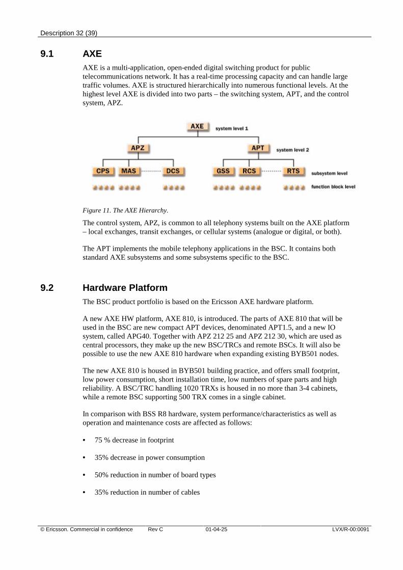
9.1 AXEAXE is a multi-application, open-ended digital switching product for publictelecommunications network. It has a real-time processing capacity and can handle largetraffic volumes. AXE is structured hierarchically into numerous functional levels. At thehighest level AXE is divided into two parts – the switching system, APT, and the controlsystem, APZ.
Figure 11. The AXE Hierarchy.
The control system, APZ, is common to all telephony systems built on the AXE platform– local exchanges, transit exchanges, or cellular systems (analogue or digital, or both).
The APT implements the mobile telephony applications in the BSC. It contains bothstandard AXE subsystems and some subsystems specific to the BSC.
9.2 Hardware PlatformThe BSC product portfolio is based on the Ericsson AXE hardware platform.
A new AXE HW platform, AXE 810, is introduced. The parts of AXE 810 that will beused in the BSC are new compact APT devices, denominated APT1.5, and a new IOsystem, called APG40. Together with APZ 212 25 and APZ 212 30, which are used ascentral processors, they make up the new BSC/TRCs and remote BSCs. It will also bepossible to use the new AXE 810 hardware when expanding existing BYB501 nodes.
The new AXE 810 is housed in BYB501 building practice, and offers small footprint,low power consumption, short installation time, low numbers of spare parts and highreliability. A BSC/TRC handling 1020 TRXs is housed in no more than 3-4 cabinets,while a remote BSC supporting 500 TRX comes in a single cabinet.
In comparison with BSS R8 hardware, system performance/characteristics as well asoperation and maintenance costs are affected as follows:
• 75 % decrease in footprint
• 35% decrease in power consumption
• 50% reduction in number of board types
• 35% reduction in number of cables
Description 33 (39)
LVX/R-00:0091 Rev C 01-04-25 © Ericsson. Commercial in confidence
• 35% decrease in failure rate
APT1.5APT1.5 constitutes the following parts:
• GEM - Generic Ericsson Magazine
• New STM switch - Distributed, non blocking switch, providing unlimited subrateswitch capacity
• TRA R6 - 192 HR/FR/EFR channels per board
• ET155-1 – ET155 on a single board
• RPG3 - RPG on a single board
The STM switch together with the TRA R6 and ET155-1 device boards is housed in theGEM subrack. The RPG3 on the other hand is still housed in conventional BYB501subracks. The switch capacity of each GEM is 16 k ports, and several GEM can beconnected to form switches with higher capacity. The new switch offers unlimitedsubrate switching capacity, which enables unlimited amounts of half rate and data trafficwithin a node.
APG40APG40 is a new IO system for AXE nodes and a successor to the current IO systems,IOG20 and IOG11. APG40 is mainly based on third party and industry standardproducts. For example, Windows NT is used as operating system and pentiumprocessors as central processing units. When the APZ 212 30 is used, thecommunication bus between the CP and the IO system is based on 100 Mbit/s fastEthernet, resulting in decreased times for backup and reload from the IO system. TCP/IPcommunication towards OSS is also supported.
The main benefits of using APG40 are:
• Increased processing capacity
• Increased data throughput between CP and IO system, for example, 1 million STScounters per 15 minutes from CP to IO.
• Standard TCP/IP based communication
• A platform for future applications such as real time event data
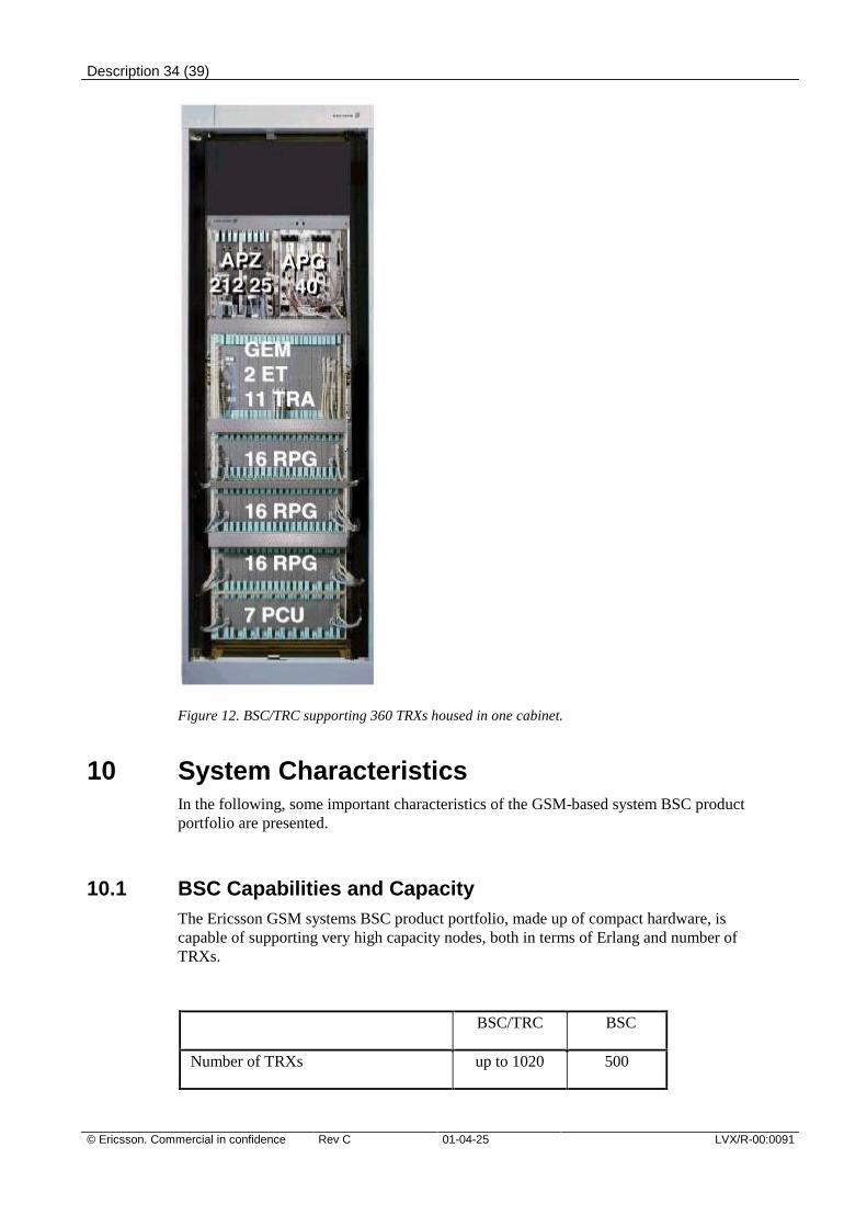
Description 34 (39)
© Ericsson. Commercial in confidence Rev C 01-04-25 LVX/R-00:0091
Figure 12. BSC/TRC supporting 360 TRXs housed in one cabinet.
10 System CharacteristicsIn the following, some important characteristics of the GSM-based system BSC productportfolio are presented.
10.1 BSC Capabilities and CapacityThe Ericsson GSM systems BSC product portfolio, made up of compact hardware, iscapable of supporting very high capacity nodes, both in terms of Erlang and number ofTRXs.
BSC/TRC BSC
Number of TRXs up to 1020 500
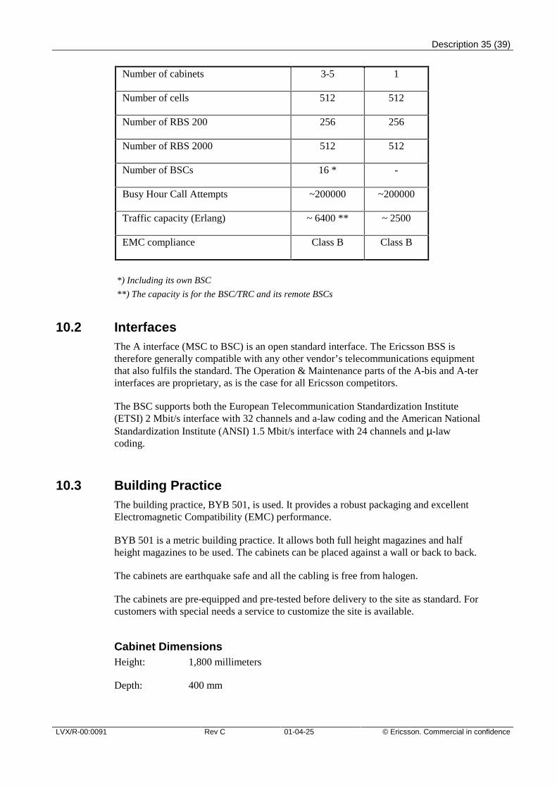
Description 35 (39)
LVX/R-00:0091 Rev C 01-04-25 © Ericsson. Commercial in confidence
Number of cabinets 3-5 1
Number of cells 512 512
Number of RBS 200 256 256
Number of RBS 2000 512 512
Number of BSCs 16 * -
Busy Hour Call Attempts ~200000 ~200000
Traffic capacity (Erlang) ~ 6400 ** ~ 2500
EMC compliance Class B Class B
*) Including its own BSC
**) The capacity is for the BSC/TRC and its remote BSCs
10.2 InterfacesThe A interface (MSC to BSC) is an open standard interface. The Ericsson BSS istherefore generally compatible with any other vendor’s telecommunications equipmentthat also fulfils the standard. The Operation & Maintenance parts of the A-bis and A-terinterfaces are proprietary, as is the case for all Ericsson competitors.
The BSC supports both the European Telecommunication Standardization Institute(ETSI) 2 Mbit/s interface with 32 channels and a-law coding and the American NationalStandardization Institute (ANSI) 1.5 Mbit/s interface with 24 channels and µ-lawcoding.
10.3 Building PracticeThe building practice, BYB 501, is used. It provides a robust packaging and excellentElectromagnetic Compatibility (EMC) performance.
BYB 501 is a metric building practice. It allows both full height magazines and halfheight magazines to be used. The cabinets can be placed against a wall or back to back.
The cabinets are earthquake safe and all the cabling is free from halogen.
The cabinets are pre-equipped and pre-tested before delivery to the site as standard. Forcustomers with special needs a service to customize the site is available.
Cabinet DimensionsHeight: 1,800 millimeters
Depth: 400 mm
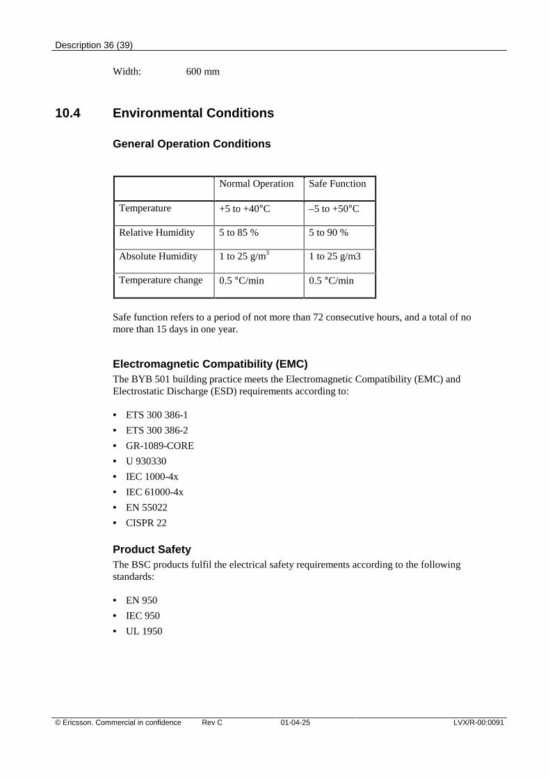
Description 36 (39)
© Ericsson. Commercial in confidence Rev C 01-04-25 LVX/R-00:0091
Width: 600 mm
10.4 Environmental Conditions
General Operation Conditions
Normal Operation Safe Function
Temperature +5 to +40°C –5 to +50°C
Relative Humidity 5 to 85 % 5 to 90 %
Absolute Humidity 1 to 25 g/m3 1 to 25 g/m3
Temperature change 0.5 °C/min 0.5 °C/min
Safe function refers to a period of not more than 72 consecutive hours, and a total of nomore than 15 days in one year.
Electromagnetic Compatibility (EMC)The BYB 501 building practice meets the Electromagnetic Compatibility (EMC) andElectrostatic Discharge (ESD) requirements according to:
• ETS 300 386-1
• ETS 300 386-2
• GR-1089-CORE
• U 930330
• IEC 1000-4x
• IEC 61000-4x
• EN 55022
• CISPR 22
Product SafetyThe BSC products fulfil the electrical safety requirements according to the followingstandards:
• EN 950
• IEC 950
• UL 1950
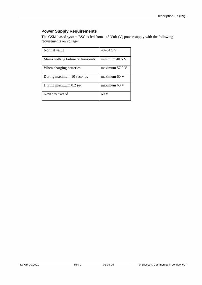
Description 37 (39)
LVX/R-00:0091 Rev C 01-04-25 © Ericsson. Commercial in confidence
Power Supply RequirementsThe GSM-based system BSC is fed from –48 Volt (V) power supply with the followingrequirements on voltage:
Normal value 48–54.5 V
Mains voltage failure or transients minimum 40.5 V
When charging batteries maximum 57.0 V
During maximum 10 seconds maximum 60 V
During maximum 0.2 sec maximum 60 V
Never to exceed 60 V
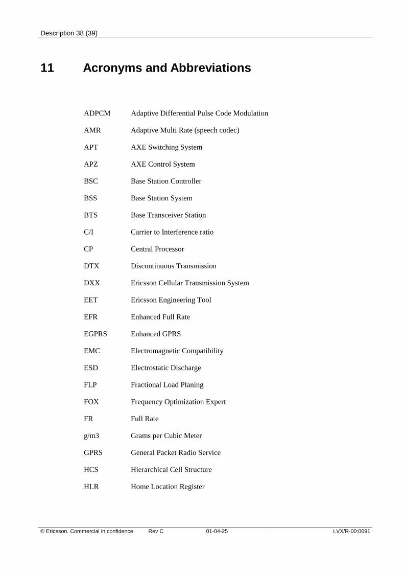
Description 38 (39)
© Ericsson. Commercial in confidence Rev C 01-04-25 LVX/R-00:0091
11 Acronyms and Abbreviations
ADPCM Adaptive Differential Pulse Code Modulation
AMR Adaptive Multi Rate (speech codec)
APT AXE Switching System
APZ AXE Control System
BSC Base Station Controller
BSS Base Station System
BTS Base Transceiver Station
C/I Carrier to Interference ratio
CP Central Processor
DTX Discontinuous Transmission
DXX Ericsson Cellular Transmission System
EET Ericsson Engineering Tool
EFR Enhanced Full Rate
EGPRS Enhanced GPRS
EMC Electromagnetic Compatibility
ESD Electrostatic Discharge
FLP Fractional Load Planing
FOX Frequency Optimization Expert
FR Full Rate
g/m3 Grams per Cubic Meter
GPRS General Packet Radio Service
HCS Hierarchical Cell Structure
HLR Home Location Register
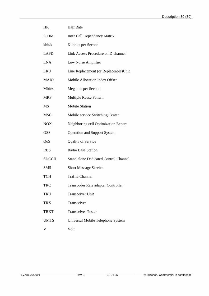
Description 39 (39)
LVX/R-00:0091 Rev C 01-04-25 © Ericsson. Commercial in confidence
HR Half Rate
ICDM Inter Cell Dependency Matrix
kbit/s Kilobits per Second
LAPD Link Access Procedure on D-channel
LNA Low Noise Amplifier
LRU Line Replacement (or Replaceable)Unit
MAIO Mobile Allocation Index Offset
Mbit/s Megabits per Second
MRP Multiple Reuse Pattern
MS Mobile Station
MSC Mobile service Switching Center
NOX Neighboring cell Optimization Expert
OSS Operation and Support System
QoS Quality of Service
RBS Radio Base Station
SDCCH Stand alone Dedicated Control Channel
SMS Short Message Service
TCH Traffic Channel
TRC Transcoder Rate adapter Controller
TRU Transceiver Unit
TRX Transceiver
TRXT Transceiver Tester
UMTS Universal Mobile Telephone System
V Volt