Embed Size (px)
Citation preview
7/21/2019 BSS Architecture Service Guideline B10
http://slidepdf.com/reader/full/bss-architecture-service-guideline-b10 1/154
Alcatel File Reference Date Edition Page
B10_BSS_arch_serv_GuideLine_Ed1.doc 3DF 01903 8010 VAZZA 01 March 04, 2008 1 1 / 154
Site
Vélizy Mobile Radio Division
Originator(s)
A. Rezzoug
E. Marza
B10: BSS Architecture Service Guideline
Domain : Network Architecture
Product : GSM B10
Division : Methods
Rubric : GSM/GPRS/EDGEType : Guidelines
Distribution codes Internal:
Pre-distribution:
NE Velizy NE Timisora NE Portugal NE Egypt
F. Colin Cristian I. Inta Pedro Henriques Wessam Yanni
T. Plantier E. Marza Tiago Dias
M. Talayssat João Frade
LM. Palumbo
Abstract: The aim of this document is to describe BSS architecture configuration rules &
dimensioning processes in Alcatel release B10. It is recommended to be the guideline for
RNE & TPM people who are involve in BSS architecture aspect.
Key words: BTS, BSC, TC, MFS/GP(U), Abis, AterMUX, A, and Gb; B10 release
Appraisal and approval authorities
GSM TIS
DD-MM-YY: Signature: DD-MM-YY: Signature:
Network Engineering Florent Colin
DD-MM-YY: Signature:
All Alcatel system details given in this document are for your comfort only. The system
information may not reflect the latest status of the equipment used in your project.
Please consult in addition to this document the latest product descriptions!
7/21/2019 BSS Architecture Service Guideline B10
http://slidepdf.com/reader/full/bss-architecture-service-guideline-b10 2/154
Alcatel File Reference Date Edition Page
B10_BSS_arch_serv_GuideLine_Ed1.doc 3DF 01903 8010 VAZZA 01 March 04, 2008 1 2 / 154
Table of contents
1 INTRODUCTION..................................................................................... 14
2 OVERVIEW OF BSS ARCHITECTURE SERVICES ........................15
2.1 WHAT IS THE BSS ARCHITECTURE ? .......................................................................... 15
2.1.1 BSS Network Elements ..................................................................................... 15
2.1.2 BSS Interfaces .................................................................................................. 16
2.1.2.1 Um (air or radio) interface ........................................................................... 16
2.1.2.2 Abis interface ............................................................................................... 16
2.1.2.3 AterMUX interface ......................................................................................16
2.1.2.4 A interface .................................................................................................... 17
2.1.2.5 Gb interface .................................................................................................. 17
2.2 BSS ARCHITECTURE SERVICES................................................................................... 18
2.2.1 Scope ................................................................................................................18
2.2.2 Goal.................................................................................................................. 18
2.2.3 Category........................................................................................................... 18
2.2.4 Process .............................................................................................................19 2.2.4.1 Process for Network Architecture SETUP and EVOLUTION....................19
2.2.4.2 Process for Network Architecture ASSESSMENT ..................................... 22
2.3 BSS ARCHITECTURE IMPACT – IN B10 ....................................................................... 25
2.3.1 Multiple CCCH ................................................................................................ 25
2.3.2 Gb over IP ........................................................................................................ 26
2.3.3 Capacity Improvements.................................................................................... 27
2.3.3.1 Optimized HR connectivity.......................................................................... 28
2.3.3.2 HSL functionality.........................................................................................28
3 DETAILED BSS ARCHITECTURE PROCESS ..................................29
3.1 BTS ............................................................................................................................ 29
3.1.1 BTS Configuration............................................................................................29
3.1.1.1 Cell Configuration........................................................................................ 33
3.1.1.2 SDCCH Configuration ................................................................................. 34
3.1.2 Determination of BTS configuration................................................................36
3.1.3 Cell dimensioning............................................................................................. 36
7/21/2019 BSS Architecture Service Guideline B10
http://slidepdf.com/reader/full/bss-architecture-service-guideline-b10 3/154
Alcatel File Reference Date Edition Page
B10_BSS_arch_serv_GuideLine_Ed1.doc 3DF 01903 8010 VAZZA 01 March 04, 2008 1 3 / 154
3.1.3.1 SDCCH Dimensioning................................................................................. 37
3.1.3.2 TCH/PDCH Dimensioning .......................................................................... 39
3.2 ABIS I NTERFACE ......................................................................................................... 45
3.2.1 Abis Configuration...........................................................................................45
3.2.1.1 Abis Network Topology............................................................................... 45
3.2.1.2 Abis Channels .............................................................................................. 47
3.2.1.3 Abis Link Capacity....................................................................................... 49
3.2.1.4 Signalling Sub-Multiplexing Schemes.........................................................49
3.2.1.4.1 No Multiplexing............... ....................... .................... ....................... .................. ...................... 50
3.2.1.4.2 16K Static Multiplexing............................................................................................................. 50
3.2.1.4.3 64K Statistical Multiplexing ..................... ..................... ....................... .................. ................... 51
3.2.1.4.4 16K Statistical Multiplexing ..................... ..................... ....................... .................. ................... 54
3.2.1.5 Secondary Abis Link.................................................................................... 55
3.2.2 Abis Dimensioning ...........................................................................................57
3.2.2.1 Case #1: B9 with No GPRS/EDGE B10 with EDGE............................. 59
3.2.2.2 Case #2: B10 with EDGE............................................................................. 59
3.3 BSC ............................................................................................................................ 66
3.3.1 G2 BSC Configuration ..................................................................................... 66
3.3.1.1 BSC Capacity ............................................................................................... 67
3.3.1.2 Abis TSU...................................................................................................... 68
3.3.1.3 Ater TSU ...................................................................................................... 70
3.3.2 BSC Evolution Configuration........................................................................... 70
3.3.2.1 BSC Capacity ............................................................................................... 72
3.3.2.2 Delta BSC Evolution versus G2 BSC .......................................................... 73
3.3.2.3 CCP board .................................................................................................... 73
3.3.2.4 LIU shelf ...................................................................................................... 75
3.3.2.5 SS7 transport ................................................................................................ 75
3.3.3 BSC Dimensioning ...........................................................................................76
3.3.3.1 Design BSC area ..........................................................................................77
3.3.3.2 Parenting Abis ports of the BSC ..................................................................79
3.3.4 LA Dimensioning.............................................................................................. 81
3.3.5 RA Dimensioning..............................................................................................85
3.3.6 Summary of LA/RA dimensioning process ....................................................... 87
3.3.7 CCCH dimensioning ........................................................................................ 88
7/21/2019 BSS Architecture Service Guideline B10
http://slidepdf.com/reader/full/bss-architecture-service-guideline-b10 4/154
Alcatel File Reference Date Edition Page
B10_BSS_arch_serv_GuideLine_Ed1.doc 3DF 01903 8010 VAZZA 01 March 04, 2008 1 4 / 154
3.4 ATER MUX AND A INTERFACES.................................................................................. 89
3.4.1 General............................................................................................................. 89
3.4.1.1 AterMUX interface ......................................................................................89
3.4.1.2 A interface .................................................................................................... 89
3.4.1.3 AterMUX interface versus A interface ........................................................ 89
3.4.2 AterMUX configuration.................................................................................... 90
3.4.2.1 AterMUX CS and A interfaces ....................................................................91
3.4.2.2 AterMUX PS................................................................................................ 93
3.4.2.3 AterMUX CS/PS.......................................................................................... 94
3.4.3 SS7 Signalling mode......................................................................................... 96
3.4.3.1 LSL and HSL modes .................................................................................... 96
3.4.3.2 SS7 Dimensioning........................................................................................ 97
3.4.4 AterMUX Dimensioning................................................................................. 101
3.4.4.1 AterMUX CS.............................................................................................. 101
3.4.4.1.1 A Dimensioning....................................................................................................................... 104
3.4.4.2 AterMUX PS.............................................................................................. 105
3.4.4.2.1 Process description .................................................................................................................. 105
3.4.4.2.2 GSL Dimensioning ..................... .................... ....................... ........................ .................. ........ 108
3.4.4.2.3 GCH/AterMUX-PS Dimensioning .......................................................................................... 113
3.4.4.3 AterMUX CS/PS........................................................................................115
3.5 TC............................................................................................................................. 116
3.5.1 G2 TC Configuration ..................................................................................... 117
3.5.2 G2.5 TC Configuration .................................................................................. 117
3.5.3 TC Dimensioning............................................................................................ 118
3.6 MFS..........................................................................................................................120
3.6.1 The 1st MFS generation (A9135 MFS) ........................................................... 120
3.6.1.1 GPRS Processing Unit (GPU).................................................................... 121
3.6.1.2 Multiple GPU per BSS............................................................................... 121
3.6.1.3 Capacity...................................................................................................... 122
3.6.2 MFS Evolution (A9130 MFS)......................................................................... 122
3.6.2.1 Configurations and Capacity...................................................................... 123
3.6.2.2 Delta MFS Evolution versus the 1st MFS generation................................. 124
3.6.3 GP(U) Dimensioning and AterMux PS dimensioning (user traffic) ..............125
3.6.3.1 Required GCH traffic estimation in case of stable network....................... 128

7/21/2019 BSS Architecture Service Guideline B10
http://slidepdf.com/reader/full/bss-architecture-service-guideline-b10 5/154
Alcatel File Reference Date Edition Page
B10_BSS_arch_serv_GuideLine_Ed1.doc 3DF 01903 8010 VAZZA 01 March 04, 2008 1 5 / 154
3.6.3.2 Required GCH estimation in anticipation of feature activation.................130
3.6.3.2.1 Increase_factor estimation ..................... .................... ........................ .................. .................... 131
3.6.3.3 GP(U) GCH capacity estimation................................................................ 132
3.6.3.4 GP(U) limitations .......................................................................................134
3.7 GB INTERFACE .......................................................................................................... 138
3.7.1 Gb configuration ............................................................................................ 140
3.7.2 Gb Dimensioning............................................................................................ 142
4 ANNEX 1: BSS ARCHITECTURE IMPACT FROM B9.................. 145
5 ANNEX 2: PRE-REQUISITES FOR MXBSC CAPACITY
IMPROVEMENTS ......................................................................................... 150
5.1 CIC CODE LIMITATION .............................................................................................. 150
5.2 HSL LIMITATION ...................................................................................................... 150
5.3 GBOIP LIMITATION ................................................................................................... 151
6 ANNEX 3: ABIS, ATER & GB OVER SATELLITE ......................... 153
7 ANNEX 4: TRANSPORT MIGRATION............................................. 154
7.1 OPTIMISATION OVER E1............................................................................................ 154
7.2 IP BACKHAULING ...................................................................................................... 154
7/21/2019 BSS Architecture Service Guideline B10
http://slidepdf.com/reader/full/bss-architecture-service-guideline-b10 6/154
Alcatel File Reference Date Edition Page
B10_BSS_arch_serv_GuideLine_Ed1.doc 3DF 01903 8010 VAZZA 01 March 04, 2008 1 6 / 154
INDEX OF FIGURES
Figure 1: BSS Architecture ...................................................................................................... 15
Figure 2: TRX configuration on Um interface......................................................................... 16
Figure 3: Abis configuration .................................................................................................... 16
Figure 4: AterMUX configuration – Dedicated AterMUX for CS traffic ............................... 17
Figure 5: A-interface configuration.......................................................................................... 17
Figure 6: BSS Architecture Services........................................................................................ 18
Figure 7: Network Architecture Setup and Evolution process.................................................19
Figure 8: BSC/LAC/RAC (re) design - example .....................................................................20
Figure 9: Abis TSU port (re) design......................................................................................... 22
Figure 10: Network architecture assessment process............................................................... 23
Figure 11: mCCCH mapping on Beacon TRX ........................................................................ 25
Figure 12: MFS capacity.......................................................................................................... 27
Figure 13: B10 BSC capacity improvements........................................................................... 27
Figure 14: BSC - MSC connectivity with HSL mode.............................................................. 28
Figure 15: BTS generation/type – supported in B10................................................................ 29
Figure 16: Determination of BTS configuration...................................................................... 36
Figure 17: SDCCH dimensioning process ............................................................................... 37
Figure 18: TCH/PDCH dimensioning process......................................................................... 40
Figure 19: TCH/PDCH dimensioning assessment...................................................................44
Figure 20: Abis Chain (Multi-drop) Topology ........................................................................ 45
Figure 21: Abis Star Topology.................................................................................................46
7/21/2019 BSS Architecture Service Guideline B10
http://slidepdf.com/reader/full/bss-architecture-service-guideline-b10 7/154
Alcatel File Reference Date Edition Page
B10_BSS_arch_serv_GuideLine_Ed1.doc 3DF 01903 8010 VAZZA 01 March 04, 2008 1 7 / 154
Figure 22: Abis Ring (Closed loop) Topology......................................................................... 46
Figure 23: Secondary Abis Topology ......................................................................................47
Figure 24: TRX - Abis mapping .............................................................................................. 47
Figure 25: Example of Abis TS usage for 1 BTS/4 TRX – No Multiplexing..........................50
Figure 26: Example of Abis TS usage for 1 BTS/4 TRX – 16K Static Multiplexing ............. 51
Figure 27: 64K Statistical Multiplexing – MCB 64/1 mapping...............................................51
Figure 28: 64K Statistical Multiplexing – MCB 64/2 mapping...............................................52
Figure 29: 64K Statistical Multiplexing – MCB 64/4 mapping...............................................52
Figure 30: Example of Abis TS usage for 1 BTS/4 TRX – 64K Statistical Multiplexing....... 53
Figure 31: 16K Statistical Multiplexing – MCB 16/1 mapping...............................................54
Figure 32: Example of Abis TS usage for 1 BTS/4 TRX – 16K Statistical Multiplexing....... 55
Figure 33: Abis TS configuration on primary and secondary links .........................................55
Figure 34: BTS with 24 TRX mapped on both Abis links....................................................... 56
Figure 35: Example of topology with two BTS chained.......................................................... 56
Figure 36: Two Abis links filling examples. ............................................................................ 57
Figure 37: Abis dimensioning process – Method 1.................................................................. 60
Figure 38: Abis dimensioning process – Method 2.................................................................. 63
Figure 39: Abis method algorithm ...........................................................................................64
Figure 40: Abis dimensioning process..................................................................................... 65
Figure 41: G2 BSC (A9120 BSC) Architecture....................................................................... 66
Figure 42: G2 BSC Cabinet layout ..........................................................................................67
Figure 43: Abis TSU – G2 BSC............................................................................................... 68
7/21/2019 BSS Architecture Service Guideline B10
http://slidepdf.com/reader/full/bss-architecture-service-guideline-b10 8/154
Alcatel File Reference Date Edition Page
B10_BSS_arch_serv_GuideLine_Ed1.doc 3DF 01903 8010 VAZZA 01 March 04, 2008 1 8 / 154
Figure 44: Ater TSU – G2 BSC ............................................................................................... 70
Figure 45: BSC Evolution (A9130 BSC) HW Architecture .................................................... 71
Figure 46: Abis and Ater allocation on LIU boards / BSC capacity........................................75
Figure 47: BSC dimensioning process..................................................................................... 76
Figure 48: BTS position & configuration – design BSC area step 1 .......................................77
Figure 49: Transmission planning & BSC position – design BSC area step 2 ........................ 78
Figure 50: BSC area definition – design BSC area step 3 ....................................................... 78
Figure 51: Transmission load checking ................................................................................... 79
Figure 52: BTS / Abis parenting on BSC – done by AMT.NET.............................................80
Figure 53: LA dimensioning assessment ................................................................................. 84
Figure 54: Subdivision of a LA in GPRS routing areas (RA)..................................................85
Figure 55: AterMUX and A relationship ................................................................................. 89
Figure 56: AterMUX interface structure .................................................................................. 90
Figure 57: AterMUX CS interface configuration – G2 BSC ................................................... 91
Figure 58: Channel mapping between AterMUX CS and A.................................................... 92
Figure 59: AterMUX PS interface configuration - GPU..........................................................93
Figure 60: Sharing AterMUX links..........................................................................................94
Figure 61: AterMUX CS/PS Timeslot configuration............................................................... 95
Figure 62: SS7 message length (in bytes) according to GSM event........................................97
Figure 63: Difference between Exact busy hour, NPO busy hour and Peak traffic................. 99
Figure 64: AterMUX-CS dimensioning process.................................................................... 102
Figure 65 AterMux-PS dimensioning process at BSC level .................................................. 106
7/21/2019 BSS Architecture Service Guideline B10
http://slidepdf.com/reader/full/bss-architecture-service-guideline-b10 9/154
Alcatel File Reference Date Edition Page
B10_BSS_arch_serv_GuideLine_Ed1.doc 3DF 01903 8010 VAZZA 01 March 04, 2008 1 9 / 154
Figure 66 AterMux-PS dimensioning process at GP(U) level............................................... 106
Figure 67 GSL usage factor ................................................................................................... 112
Figure 68: TC G2 architecture with mixed configuration...................................................... 116
Figure 69: TC dimensioning process .....................................................................................118
Figure 70: The 1st MFS generation (A9135 MFS) Architecture............................................ 120
Figure 71: Multiple GPU per BSS .........................................................................................121
Figure 72: MFS capacity........................................................................................................ 124
Figure 73: GP(U) dimensioning process................................................................................126
Figure 74 AterMux PS dimensioning process based on user traffic......................................127
Figure 75: Example of GCH/PDCH traffic relationship in case of AterMux PS
underdimensioning .......................................................................................................... 129
Figure 76 GCH vs. PDCH traffic relationship: example ....................................................... 130
Figure 77 GCH vs. PDCH evolution in case of EDGE/CS3/CS4 activation......................... 131
Figure 78 GPU_for_Power_Limitation due to PMU CPU load ............................................136
Figure 79 GPU_for_Power_Limitation due to DSP CPU load.............................................. 137
Figure 80: Gb interface configuration (from 3BK 09559 LAAA EBZZA)........................... 139
Figure 81: Gb interface connections ......................................................................................140
Figure 82: GboIP – End-to-End architecture ......................................................................... 141
Figure 83: Gb dimensioning process...................................................................................... 142
Figure 84: EGCH link in B8 vs. M-EGCH link in B9 ........................................................... 145
Figure 85: Wasted Abis nibbles case in B8............................................................................147
Figure 86: Enhance transmission resource management ....................................................... 147
Figure 87: AterMUX TS reserved by GP(U) Ater TS margin............................................... 148
7/21/2019 BSS Architecture Service Guideline B10
http://slidepdf.com/reader/full/bss-architecture-service-guideline-b10 10/154
Alcatel File Reference Date Edition Page
B10_BSS_arch_serv_GuideLine_Ed1.doc 3DF 01903 8010 VAZZA 01 March 04, 2008 1 10 / 154
Figure 88: Better transmission resource usage with DL retransmission in the BTS..............149
7/21/2019 BSS Architecture Service Guideline B10
http://slidepdf.com/reader/full/bss-architecture-service-guideline-b10 11/154
Alcatel File Reference Date Edition Page
B10_BSS_arch_serv_GuideLine_Ed1.doc 3DF 01903 8010 VAZZA 01 March 04, 2008 1 11 / 154
INDEX OF TABLES
Table 1: BSC-MFS/GP(U)-TC (re) design .............................................................................. 21
Table 2: Configuration – G1 BTS MKII with DRFU.............................................................. 29
Table 3: Configuration – G2 BTS ............................................................................................30
Table 4: Configuration – Evolium BTS................................................................................... 30
Table 5: Configuration – Evolium Evolution...........................................................................31
Table 6: BTS HW Capability in B10 .......................................................................................32
Table 7: TRX HW capability since G3 BTS generation.......................................................... 33
Table 8: Cell Types ..................................................................................................................33
Table 9: Frequency Hopping supported in B10 ....................................................................... 34
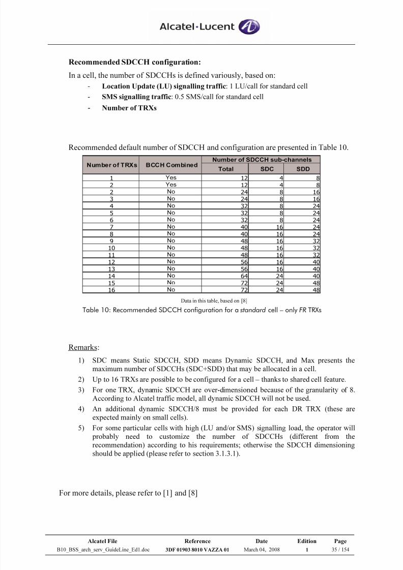
Table 10: Recommended SDCCH configuration for a standard cell – only FR TRXs...........35
Table 11: Counter list - SDCCH dimensioning ....................................................................... 37
Table 12: Counter list - TCH dimensioning............................................................................. 39
Table 13: Counter list - PDCH dimensioning .......................................................................... 40
Table 14: RLC data block size for each (M) CS...................................................................... 43
Table 15: Abis Channel Types ................................................................................................. 48
Table 16: Number of TS available in one Abis link ................................................................49
Table 17: Counter list - Abis dimensioning Method 1 ............................................................. 59
Table 18: Counter list - Abis dimensioning Method 2.1 .......................................................... 63
Table 19: G2 BSC Capacity ..................................................................................................... 67
Table 20: TSL/TCU Mapping .................................................................................................. 69
Table 21: BSC Evolution Capacity ..........................................................................................72
7/21/2019 BSS Architecture Service Guideline B10
http://slidepdf.com/reader/full/bss-architecture-service-guideline-b10 12/154
Alcatel File Reference Date Edition Page
B10_BSS_arch_serv_GuideLine_Ed1.doc 3DF 01903 8010 VAZZA 01 March 04, 2008 1 12 / 154
Table 22: Counter list – LA dimensioning............................................................................... 81
Table 23: Counter list – RA dimensioning............................................................................... 85
Table 24: Max number of AterMUX CS interfaces – G2 BSC ............................................... 92
Table 25: Max number of A-interfaces – G2 BSC................................................................... 93
Table 26: Max number of AterMUX PS– G2 BSC .................................................................94
Table 27: Ratio of Mixing CS and PS Traffic in AterMUX .................................................... 95
Table 28: Counter list – AterMUX-CS dimensioning ............................................................. 98
Table 29: Counter list – AterMUX-CS dimensioning ........................................................... 101
Table 30: Counter list – GSL dimensioning........................................................................... 109
Table 31: Counter list – GSL dimensioning........................................................................... 110
Table 32: G2 TC/ G2.5 TC capabilities ................................................................................. 116
Table 33: G2 TC configuration .............................................................................................. 117
Table 34: G2.5 TC configuration ........................................................................................... 117
Table 35: G2.5 TC capacity ................................................................................................... 118
Table 36: The 1st MFS generation (A9135 MFS) Capacity................................................... 122
Table 37: Counter list - GP(U) dimensioning ........................................................................ 126
Table 38: GCH resource increase factor ................................................................................ 132
Table 39: Counter list - Gb dimensioning.............................................................................. 142
Table 40: GCH consumption – B8 vs. B9.............................................................................. 146
7/21/2019 BSS Architecture Service Guideline B10
http://slidepdf.com/reader/full/bss-architecture-service-guideline-b10 13/154
Alcatel File Reference Date Edition Page
B10_BSS_arch_serv_GuideLine_Ed1.doc 3DF 01903 8010 VAZZA 01 March 04, 2008 1 13 / 154
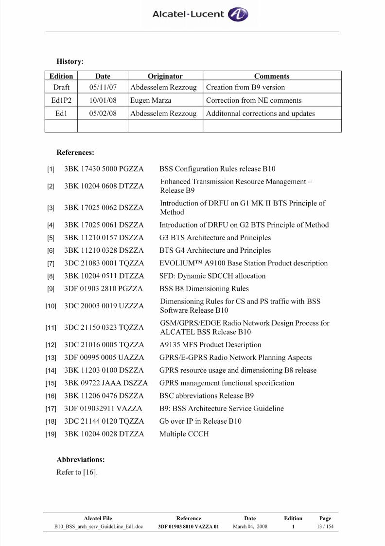
History:
Edition Date Originator Comments
Draft 05/11/07 Abdesselem Rezzoug Creation from B9 version
Ed1P2 10/01/08 Eugen Marza Correction from NE comments
Ed1 05/02/08 Abdesselem Rezzoug Additonnal corrections and updates
References:
[1] 3BK 17430 5000 PGZZA BSS Configuration Rules release B10
[2] 3BK 10204 0608 DTZZAEnhanced Transmission Resource Management –
Release B9
[3] 3BK 17025 0062 DSZZAIntroduction of DRFU on G1 MK II BTS Principle of
Method
[4] 3BK 17025 0061 DSZZA Introduction of DRFU on G2 BTS Principle of Method
[5] 3BK 11210 0157 DSZZA G3 BTS Architecture and Principles
[6] 3BK 11210 0328 DSZZA BTS G4 Architecture and Principles
[7] 3DC 21083 0001 TQZZA EVOLIUM™ A9100 Base Station Product description
[8] 3BK 10204 0511 DTZZA SFD: Dynamic SDCCH allocation
[9] 3DF 01903 2810 PGZZA BSS B8 Dimensioning Rules
[10] 3DC 20003 0019 UZZZADimensioning Rules for CS and PS traffic with BSS
Software Release B10
[11] 3DC 21150 0323 TQZZAGSM/GPRS/EDGE Radio Network Design Process for
ALCATEL BSS Release B10
[12] 3DC 21016 0005 TQZZA A9135 MFS Product Description
[13] 3DF 00995 0005 UAZZA GPRS/E-GPRS Radio Network Planning Aspects
[14] 3BK 11203 0100 DSZZA GPRS resource usage and dimensioning B8 release
[15] 3BK 09722 JAAA DSZZA GPRS management functional specification
[16] 3BK 11206 0476 DSZZA BSC abbreviations Release B9
[17] 3DF 019032911 VAZZA B9: BSS Architecture Service Guideline
[18] 3DC 21144 0120 TQZZA Gb over IP in Release B10
[19] 3BK 10204 0028 DTZZA Multiple CCCH
Abbreviations:
Refer to [16].
7/21/2019 BSS Architecture Service Guideline B10
http://slidepdf.com/reader/full/bss-architecture-service-guideline-b10 14/154
Alcatel File Reference Date Edition Page
B10_BSS_arch_serv_GuideLine_Ed1.doc 3DF 01903 8010 VAZZA 01 March 04, 2008 1 14 / 154
1 INTRODUCTION
The aim of this document is to describe BSS architecture configuration rules &
dimensioning processes in Alcatel release B10.
It is recommended to be the guideline for RNE (Radio Network Engineer) & TPM
(Technical Project Manager) people who are involve in BSS architecture aspect.
This document is organised as below:
• Part I: Overview of BSS Architecture Service
The purpose of this part is to give the reader the overview of the architecture
service for the BSS network which consists of:
- The global picture of BSS network architecture together with the short
definition for each network elements and interfaces
- Describing overall processes for each BSS architecture service
- The short presentation about B9/B10 impacts to BSS architecture.
The main impacts are linked to the new features introduced in B10 release.
• Part II: Detailed BSS Architecture Processes
This part describes in the details of the main network configuration rules in release
B10 and the dimensioning processes, which are related to counter analysis.It covers the following BSS network elements and interfaces:
- BTS
- BSC
- MFS/GP(U)
- TC
- Abis interface
- AterMUX interface
- A interface
- Gb interface
The dimensioning method due to migration from B8 to B9 release is not detailed in this
document (please refer to [17] document).
Nevertheless, a short presentation about BSS architecture impacts with the introduction
of new B9 features is presented in Annex.
7/21/2019 BSS Architecture Service Guideline B10
http://slidepdf.com/reader/full/bss-architecture-service-guideline-b10 15/154
Alcatel File Reference Date Edition Page
B10_BSS_arch_serv_GuideLine_Ed1.doc 3DF 01903 8010 VAZZA 01 March 04, 2008 1 15 / 154
2 Overview of BSS Architecture Services
This section gives an overview of the BSS architecture.
It describes briefly all the components in the BSS together with their key functions and
the global BSS architecture processes.
2.1 What is the BSS Architecture ?
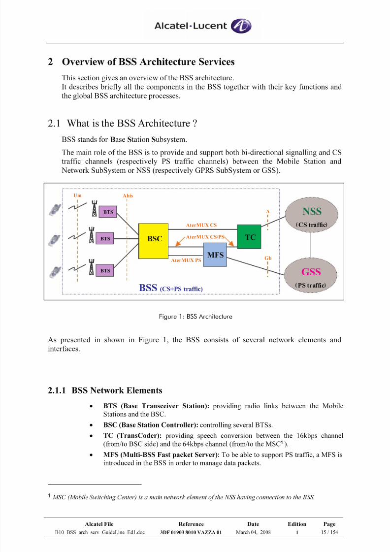
BSS stands for Base Station Subsystem.
The main role of the BSS is to provide and support both bi-directional signalling and CS
traffic channels (respectively PS traffic channels) between the Mobile Station and
Network SubSystem or NSS (respectively GPRS SubSystem or GSS).
Figure 1: BSS Architecture
As presented in shown in Figure 1, the BSS consists of several network elements and
interfaces.
2.1.1 BSS Network Elements
• BTS (Base Transceiver Station): providing radio links between the Mobile
Stations and the BSC.
• BSC (Base Station Controller): controlling several BTSs.
• TC (TransCoder): providing speech conversion between the 16kbps channel
(from/to BSC side) and the 64kbps channel (from/to the MSC1 ).• MFS (Multi-BSS Fast packet Server): To be able to support PS traffic, a MFS is
introduced in the BSS in order to manage data packets.
1 MSC (Mobile Switching Center) is a main network element of the NSS having connection to the BSS.
BTS
BTS
BTS
BSC
MFS
TC
NSS
CS traffic
GSS
PS traffic
Um Abis
AterMUX CS
Gb
A
BSS (CS+PS traffic)
AterMUX PS
AterMUX CS/PS
7/21/2019 BSS Architecture Service Guideline B10
http://slidepdf.com/reader/full/bss-architecture-service-guideline-b10 16/154
Alcatel File Reference Date Edition Page
B10_BSS_arch_serv_GuideLine_Ed1.doc 3DF 01903 8010 VAZZA 01 March 04, 2008 1 16 / 154
2.1.2 BSS Interfaces
2.1.2.1 Um (air or radio) interface
The UM interface is the radio interface connecting the MS with the BTS. It consists of agroup of TRXs and the group size is based on the BTS traffic.
TS0 TS1 TS2 TS3 TS4 TS5 TS6 TS7
TRX
Figure 2: TRX configuration on Um interface
Each TS of a TRX can provide a channel with different codec rates (FR, EFR, HR and AMR)
available for CS traffic, while GPRS CS1/CS4 and EDGE MCS-1/9 available for PS traffic.
As a radio TS is dynamically allocated to serve either CS or PS traffic, the TS is called as
TCH while it supports CS traffic; otherwise called as PDCH while it supports PS traffic.
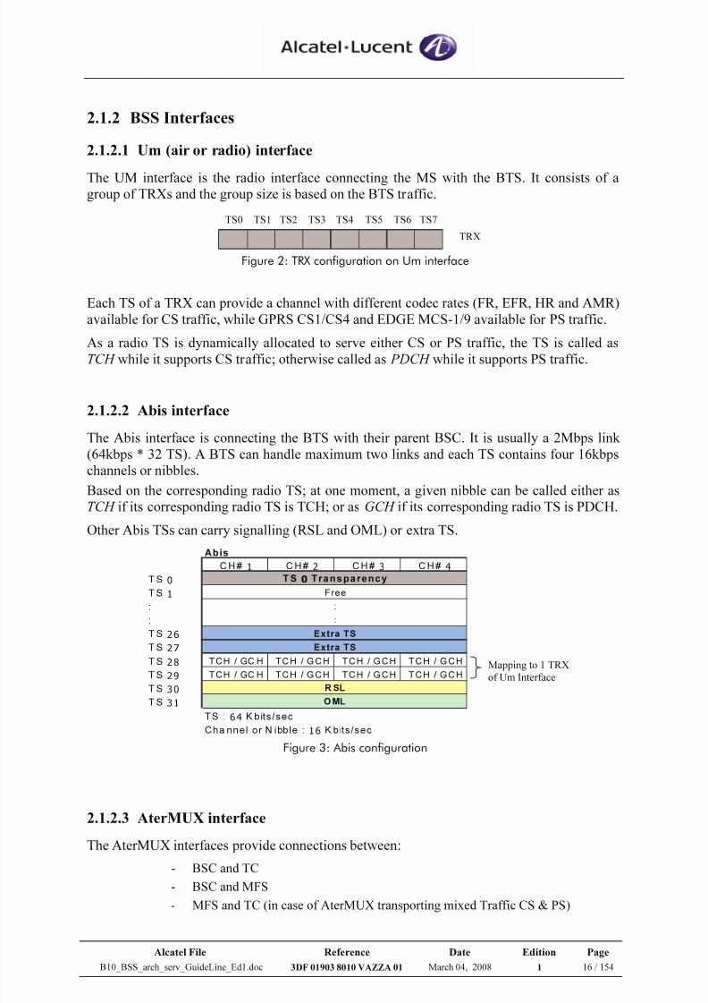
2.1.2.2 Abis interface
The Abis interface is connecting the BTS with their parent BSC. It is usually a 2Mbps link
(64kbps * 32 TS). A BTS can handle maximum two links and each TS contains four 16kbps
channels or nibbles.
Based on the corresponding radio TS; at one moment, a given nibble can be called either as
TCH if its corresponding radio TS is TCH; or as GCH if its corresponding radio TS is PDCH.
Other Abis TSs can carry signalling (RSL and OML) or extra TS.
Abis
C H # 1 C H # 2 C H # 3 C H# 4
T S 0
T S 1
:
:
T S 26
T S 27
T S 28 TCH / GC H TCH / G CH TCH / G CH TCH / G CH
T S 29 TCH / GC H TCH / G CH TCH / G CH TCH / G CH
T S 30
T S 31
T S : 64 K bits/sec
Cha nnel or N ibble : 16 K bits/sec
TS 0 Transparency
O ML
R SL
Extra TS
Extra TS
:
:
Free
Mapping to 1 TRX
of Um Interface
Figure 3: Abis configuration
2.1.2.3 AterMUX interface
The AterMUX interfaces provide connections between:
- BSC and TC
- BSC and MFS
- MFS and TC (in case of AterMUX transporting mixed Traffic CS & PS)
7/21/2019 BSS Architecture Service Guideline B10
http://slidepdf.com/reader/full/bss-architecture-service-guideline-b10 17/154
Alcatel File Reference Date Edition Page
B10_BSS_arch_serv_GuideLine_Ed1.doc 3DF 01903 8010 VAZZA 01 March 04, 2008 1 17 / 154
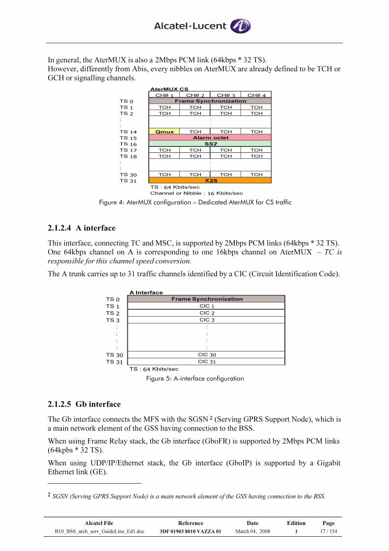
In general, the AterMUX is also a 2Mbps PCM link (64kbps * 32 TS).
However, differently from Abis, every nibbles on AterMUX are already defined to be TCH or
GCH or signalling channels.
AterMUX CS
CH# 1 CH# 2 CH# 3 CH# 4TS 0
TS 1 TCH TCH TCH TCH
TS 2 TCH TCH TCH TCH
:
:
TS 14 Qmux TCH TCH TCH
TS 15
TS 16
TS 17 TCH TCH TCH TCH
TS 18 TCH TCH TCH TCH
:
:
TS 30 TCH TCH TCH TCH
TS 31
TS : 64 Kbits/sec
Channel or Nibble : 16 Kbits/sec
Frame Synchronization
Alarm octet
SS7
X25
:
:
:
:
Figure 4: AterMUX configuration – Dedicated AterMUX for CS traffic
2.1.2.4 A interface
This interface, connecting TC and MSC, is supported by 2Mbps PCM links (64kbps * 32 TS).
One 64kbps channel on A is corresponding to one 16kbps channel on AterMUX – TC is
responsible for this channel speed conversion.
The A trunk carries up to 31 traffic channels identified by a CIC (Circuit Identification Code).
A Interface
TS 0
TS 1
TS 2
TS 3
:
:
:
:
TS 30
TS 31
TS : 64 Kbits/sec
CIC 1
CIC 2
CIC 3
:
:
:
:
CIC 30
Frame Synchronization
CIC 31
Figure 5: A-interface configuration
2.1.2.5 Gb interface
The Gb interface connects the MFS with the SGSN2 (Serving GPRS Support Node), which is
a main network element of the GSS having connection to the BSS.
When using Frame Relay stack, the Gb interface (GboFR) is supported by 2Mbps PCM links
(64kpbs * 32 TS).
When using UDP/IP/Ethernet stack, the Gb interface (GboIP) is supported by a Gigabit
Ethernet link (GE).
2 SGSN (Serving GPRS Support Node) is a main network element of the GSS having connection to the BSS.
7/21/2019 BSS Architecture Service Guideline B10
http://slidepdf.com/reader/full/bss-architecture-service-guideline-b10 18/154
Alcatel File Reference Date Edition Page
B10_BSS_arch_serv_GuideLine_Ed1.doc 3DF 01903 8010 VAZZA 01 March 04, 2008 1 18 / 154
2.2 BSS Architecture Services
2.2.1 Scope
The BSS architecture services cover the main tasks to be performed for designing the BSS
network topology and for dimensioning the BSS network elements and interfaces.
2.2.2 Goal
It is to define the BSS capacity and topology, which is appropriate and necessary to be able
to support the real network traffic or to fit new requirements for network evolution.
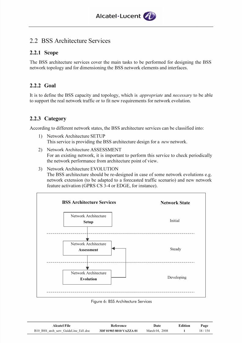
2.2.3 CategoryAccording to different network states, the BSS architecture services can be classified into:
1) Network Architecture SETUP
This service is providing the BSS architecture design for a new network.
2) Network Architecture ASSESSMENT
For an existing network, it is important to perform this service to check periodically
the network performance from architecture point of view.
3) Network Architecture EVOLUTION
The BSS architecture should be re-designed in case of some network evolutions e.g.
network extension (to be adapted to a forecasted traffic scenario) and new network feature activation (GPRS CS 3-4 or EDGE, for instance).
Network Architecture
Evolution
Network Architecture
Assessment
Network Architecture
Setup Initial
Steady
Developing
BSS Architecture Services Network State
Figure 6: BSS Architecture Services
7/21/2019 BSS Architecture Service Guideline B10
http://slidepdf.com/reader/full/bss-architecture-service-guideline-b10 19/154
Alcatel File Reference Date Edition Page
B10_BSS_arch_serv_GuideLine_Ed1.doc 3DF 01903 8010 VAZZA 01 March 04, 2008 1 19 / 154
2.2.4 Process
Two different processes are defined, one supporting the services network architecture setup
and evolution, and the other one supporting the service network architecture assessment .
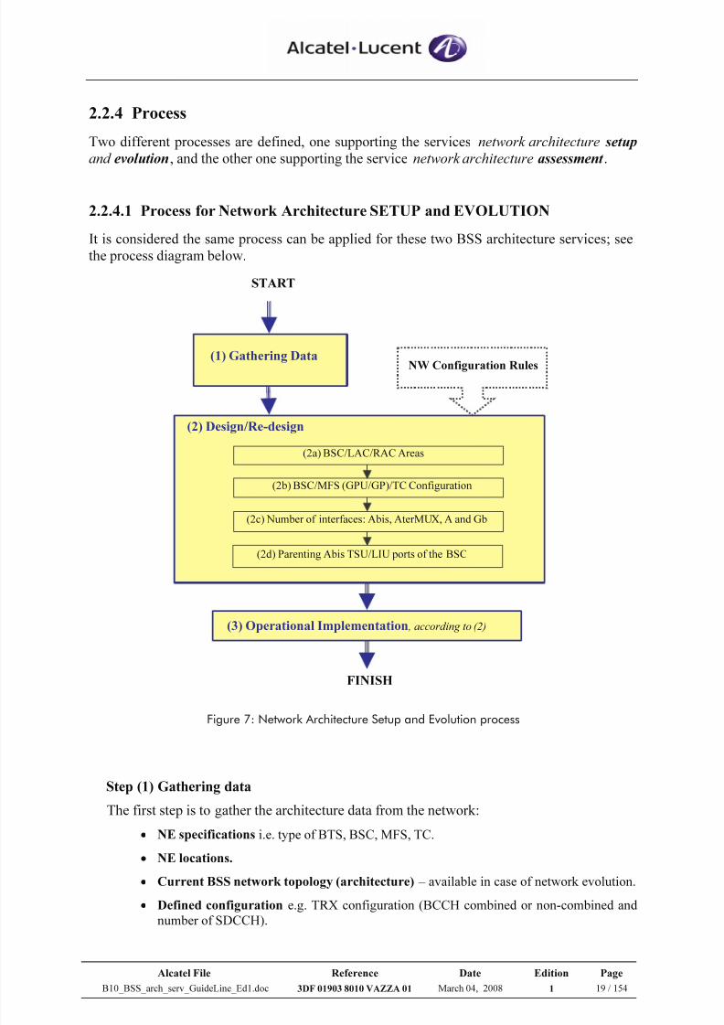
2.2.4.1 Process for Network Architecture SETUP and EVOLUTION
It is considered the same process can be applied for these two BSS architecture services; see
the process diagram below.
START
(1) Gathering Data
(2) Design/Re-design
(2b) BSC/MFS (GPU/GP)/TC Configuration
(2d) Parenting Abis TSU/LIU ports of the BSC
(2a) BSC/LAC/RAC Areas
(2c) Number of interfaces: Abis, AterMUX, A and Gb
(3) Operational Implementation , according to (2)
FINISH
NW Configuration Rules
Figure 7: Network Architecture Setup and Evolution process
Step (1) Gathering data
The first step is to gather the architecture data from the network:
• NE specifications i.e. type of BTS, BSC, MFS, TC.
• NE locations.
• Current BSS network topology (architecture) – available in case of network evolution.
• Defined configuration e.g. TRX configuration (BCCH combined or non-combined and
number of SDCCH).
7/21/2019 BSS Architecture Service Guideline B10
http://slidepdf.com/reader/full/bss-architecture-service-guideline-b10 20/154
Alcatel File Reference Date Edition Page
B10_BSS_arch_serv_GuideLine_Ed1.doc 3DF 01903 8010 VAZZA 01 March 04, 2008 1 20 / 154
Step (2) Design / Re-design
This step will be considered as design in case of network setup but re-design in case of
network evolution of which current design already existed.
The architecture (re)-design should be performed for each BSS network elements andinterfaces, based on the data from Step 1 and also strictly respected to Network
configuration rules – for more details, please refer to [1].
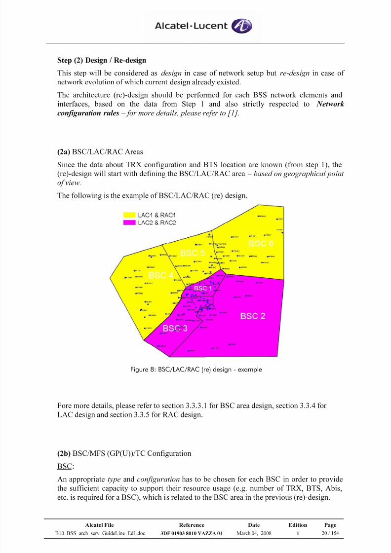
(2a) BSC/LAC/RAC Areas
Since the data about TRX configuration and BTS location are known (from step 1), the
(re)-design will start with defining the BSC/LAC/RAC area – based on geographical point
of view.
The following is the example of BSC/LAC/RAC (re) design.
Figure 8: BSC/LAC/RAC (re) design - example
Fore more details, please refer to section 3.3.3.1 for BSC area design, section 3.3.4 for
LAC design and section 3.3.5 for RAC design.
(2b) BSC/MFS (GP(U))/TC Configuration
BSC:
An appropriate type and configuration has to be chosen for each BSC in order to provide
the sufficient capacity to support their resource usage (e.g. number of TRX, BTS, Abis,
etc. is required for a BSC), which is related to the BSC area in the previous (re)-design.
7/21/2019 BSS Architecture Service Guideline B10
http://slidepdf.com/reader/full/bss-architecture-service-guideline-b10 21/154
Alcatel File Reference Date Edition Page
B10_BSS_arch_serv_GuideLine_Ed1.doc 3DF 01903 8010 VAZZA 01 March 04, 2008 1 21 / 154
MFS (GP(U)) and TC:
According to the defined BSC configuration and the CS traffic (respectively PS traffic), we
can continue to design the configuration of TC (respectively MFS/GP(U)).Therefore, the outcome of (re)-design should provide the following information.
BSC MFS/GP(U) TC
Type A9120 BSC, A9130 BSC A9135 MFS, A9130
MFS
G2 TC, G2.5 TC
(A9125 Compact TC)
Configuration - Conf 1, 2, 3, 4, 5 or 6 for
A9120 BSC
- Stand Alone / Rack shared
configuration with 200, 400,600, 800 or 1000 TRX for
A9130 BSC
Nb of GP(U) boards
dedicated to each
BSC
Nb of MFS racks
- Nb of TC boards
dedicated to each BSC
- Nb of TC racks
Table 1: BSC-MFS/GP(U)-TC (re) design
Fore more details, please refer to section 3.3 for BSC configuration, section 3.5 for TC
configuration, and section 3.6 for MFS configuration.
(2c) Number of interfaces; Abis, AterMUX, A and GbAfter the configuration of all BSS network elements is defined, it comes to the step to
design interfaces connecting them.
In general, we have to design the number of needed interface links.
However, additional characteristic has to be designed for some interfaces:
• Abis: Type of signalling sub-multiplexing schemes, BTS in multidrop and number
of extra Abis TS (in case of supporting GPRS CS3-4 and EDGE).
• AterMUX: Type of Traffic i.e. CS, PS or Mixed CS/PS.
• Gb: Number of 64kbps TSs for GboFR
Minimum throughput of IP network (QoS, Delay) for GboIP
Fore more details, please refer to section 3.2 for Abis, section 3.4 for AterMUX & A-
interface and section 3.7 for Gb.
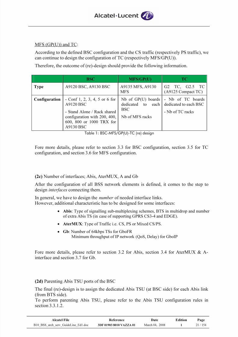
(2d) Parenting Abis TSU ports of the BSC
The final (re)-design is to assign the dedicated Abis TSU (at BSC side) for each Abis link
(from BTS side).To perform parenting Abis TSU, please refer to the Abis TSU configuration rules in
section 3.3.1.2.
7/21/2019 BSS Architecture Service Guideline B10
http://slidepdf.com/reader/full/bss-architecture-service-guideline-b10 22/154
Alcatel File Reference Date Edition Page
B10_BSS_arch_serv_GuideLine_Ed1.doc 3DF 01903 8010 VAZZA 01 March 04, 2008 1 22 / 154
However, Network Engineering service has developed the architecture management tool,
so called AMT.NET , which assists the radio network engineer to design efficiently the
parenting Abis TSU in the convenient way.
For more details, please refer to website http://pcs.tm.alcatel.ro/Amt.
Below is an example of parenting Abis TSU, which is done by AMT.NET tool.
Figure 9: Abis TSU port (re) design
Step (3) Operational Implementation
According to the results from all architecture (re)-designs in step 2, the operational
implementation should include the following activities:
• The extension of Network elements i.e. new configuration and/or new resources.
• BTS Cutover, either intra BSC (i.e. change the connected Abis TSU port within
the same BSC) or inter BSC (different BSC). • Parameter modification.
2.2.4.2 Process for Network Architecture ASSESSMENT
The aim of the process is:
- To analyze traffic flows in the network at different levels (NE & Interfaces).
- To assess the actual flows versus the installed BSS architecture capacity: over
dimensioning implies over investment, under dimensioning implies bottlenecks,congestion and unbalanced investments.
7/21/2019 BSS Architecture Service Guideline B10
http://slidepdf.com/reader/full/bss-architecture-service-guideline-b10 23/154
Alcatel File Reference Date Edition Page
B10_BSS_arch_serv_GuideLine_Ed1.doc 3DF 01903 8010 VAZZA 01 March 04, 2008 1 23 / 154
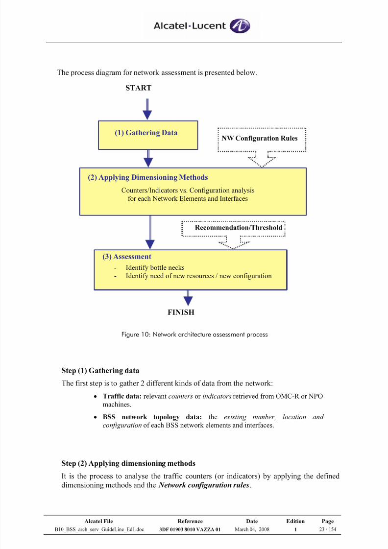
The process diagram for network assessment is presented below.
FINISH
START
(1) Gathering DataNW Configuration Rules
Recommendation/Threshold
(2) Applying Dimensioning Methods
Counters/Indicators vs. Configuration analysisfor each Network Elements and Interfaces
(3) Assessment - Identify bottle necks
- Identify need of new resources / new configuration
Figure 10: Network architecture assessment process
Step (1) Gathering data
The first step is to gather 2 different kinds of data from the network:• Traffic data: relevant counters or indicators retrieved from OMC-R or NPO
machines.
• BSS network topology data: the existing number, location and
configuration of each BSS network elements and interfaces.
Step (2) Applying dimensioning methods
It is the process to analyse the traffic counters (or indicators) by applying the defined
dimensioning methods and the Network configuration rules.
7/21/2019 BSS Architecture Service Guideline B10
http://slidepdf.com/reader/full/bss-architecture-service-guideline-b10 24/154
Alcatel File Reference Date Edition Page
B10_BSS_arch_serv_GuideLine_Ed1.doc 3DF 01903 8010 VAZZA 01 March 04, 2008 1 24 / 154
The traffic analysis should be done individually at different level of NE and interfaces.
BSS network elements:
• CELL dimensioning (for more details, please refer to section 3.1.3)
• BSC dimensioning (for more details, please refer to section 3.3.3)
• TC dimensioning (for more details, please refer to section 3.5.3)
• GP(U) dimensioning (for more details, please refer to section 3.6.3)
BSS interfaces:
• Abis dimensioning (for more details, please refer to section 3.2.2)
• AterMUX dimensioning (for more details, please refer to section 3.4.4)
• A dimensioning (for more details, please refer to section 3.4.4.1)
• Gb dimensioning (for more details, please refer to section 3.7.2)
Step (3) Assessment
This is the last process to assess the installed capacity versus used capacity (refer to the
traffic analysis results from step 2), based on the recommendation and given threshold at
all levels of the BSS.
The assessment can identify the existing bottleneck that implies the lack of resources or
unbalanced resource usage.
Therefore, the proposed solutions should be implementing new resources and/or new
configuration and probably parameter modification.
7/21/2019 BSS Architecture Service Guideline B10
http://slidepdf.com/reader/full/bss-architecture-service-guideline-b10 25/154
Alcatel File Reference Date Edition Page
B10_BSS_arch_serv_GuideLine_Ed1.doc 3DF 01903 8010 VAZZA 01 March 04, 2008 1 25 / 154
2.3 BSS Architecture Impact – in B10
In B10 release, there are several improvements in term of architecture point of view.
These improvements are related to the introduction of new features as follows:
• Multiple CCCH (B10MR1)
• Gb over IP (B10MR2)
• Capacity Improvements (4000Erl in B10MR1, 4500Erl in B10MR2)
• Optimized HR connectivity (B10MR1)
• HSL functionality (B10MR1)
2.3.1 Multiple CCCH
The multiple CCCH (mCCCH) feature is required to support the increasing signalling load on
the common channels, due to either big CS cells with high peak throughput or to PS traffic
when no master PDCH is configured.
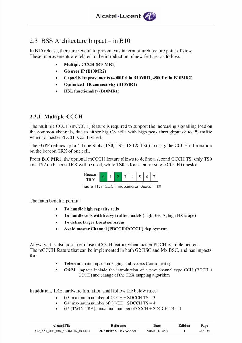
The 3GPP defines up to 4 Time Slots (TS0, TS2, TS4 & TS6) to carry the CCCH information
on the beacon TRX of one cell.
From B10 MR1, the optional mCCCH feature allows to define a second CCCH TS: only TS0
and TS2 on beacon TRX will be used, while TS0 is foreseen for single CCCH timeslot.
0 21 3 4 5 6 7Beacon
TRX
0 21 3 4 5 6 7Beacon
TRX Figure 11: mCCCH mapping on Beacon TRX
The main benefits permit:
• To handle high capacity cells
• To handle cells with heavy traffic models (high BHCA, high HR usage)
• To define larger Location Areas
• Avoid master Channel (PBCCH/PCCCH) deployment
Anyway, it is also possible to use mCCCH feature when master PDCH is implemented.
The mCCCH feature that can be implemented in both G2 BSC and Mx BSC, and has impacts
for:
Telecom: main impact on Paging and Access Control entity
O&M: impacts include the introduction of a new channel type CCH (BCCH +
CCCH) and change of the TRX mapping algorithm
In addition, TRE hardware limitation shall follow the below rules:
• G3: maximum number of CCCH + SDCCH TS = 3
• G4: maximum number of CCCH + SDCCH TS = 4
• G5 (TWIN TRA): maximum number of CCCH + SDCCH TS = 4
7/21/2019 BSS Architecture Service Guideline B10
http://slidepdf.com/reader/full/bss-architecture-service-guideline-b10 26/154
Alcatel File Reference Date Edition Page
B10_BSS_arch_serv_GuideLine_Ed1.doc 3DF 01903 8010 VAZZA 01 March 04, 2008 1 26 / 154
The mCCCH feature has impacts in the Paging and Access Control entity.
On radio interface, the capacity of the PCH paging channel will allow about 63 paging/s.
The following set of rules applying for the configuration of mCCCH:
1) CCH should be configured on TS2 of BCCH TRX
2) When BCCH is combined with SDCCH, CCH cannot be configured.
3) In BCCH TRX, when CCH is configured, only one Static SDCCH is allowed
4) In the cell with both BCC and CCH, the max number of SDCCH TS is extended to 22.
5) CBC and CBH are forbidden
6) Dynamic SDCCH is forbidden on BCCH TRX
7) Limitation rule on G2 TCU shall respect CCCH (BCCH) TS +SDCCH TS <= 4 TS
(one CCCH TS equal to one SDCCH TS in terms of signalling load)
8) The new channel type for CCCH is taken as “bonus” nibble in Abis interface.
Note: CCH is the new channel type for BCCH + CCCH;BCC is the channel type for FCCH + SCH + BCCH + CCCH.
2.3.2 Gb over IP
From B10 MR2 only, the Gb interface can be transported either on Frame Relay (GboFR) or
IP (GboIP) protocol stacks.The feature Gb interface over IP (GboIP) is transported over a standardized protocol stack
according to 3GPP R6 (UDP/IP/Ethernet).
This feature is optional and allows the backhauling of Gb traffic over IP networks (IPv4); the
traffic flows from/to all GP(U) between MFS and SGSN can be aggregate in one single flow.
So the dimensioning of the IP network – i.e. handling GboIP traffic – shall be done MFS per
MFS instead of a per GP(U) dimensioning basis.
Indeed the IP bandwidth is dynamically shared between all GP(U) within one MFS, and there
is no service differentiation between handled traffic flows (signalling, streaming, best effort).
However, the IP network between SGSN and MFS shall provide enough bandwidth to pass all
aggregated flows.
The feature option, which has to be chosen per a BSC basis, is available and supported on:
• A9130 MFS without any hardware impact (IP Ready)
• A9135 MFS equipped with DS10 systems and the replacement of the switch rack by 2
new GE switches (OS-LS-6224).
• There is no GboIP support for A9135 MFS with AS800 systems
7/21/2019 BSS Architecture Service Guideline B10
http://slidepdf.com/reader/full/bss-architecture-service-guideline-b10 27/154
Alcatel File Reference Date Edition Page
B10_BSS_arch_serv_GuideLine_Ed1.doc 3DF 01903 8010 VAZZA 01 March 04, 2008 1 27 / 154
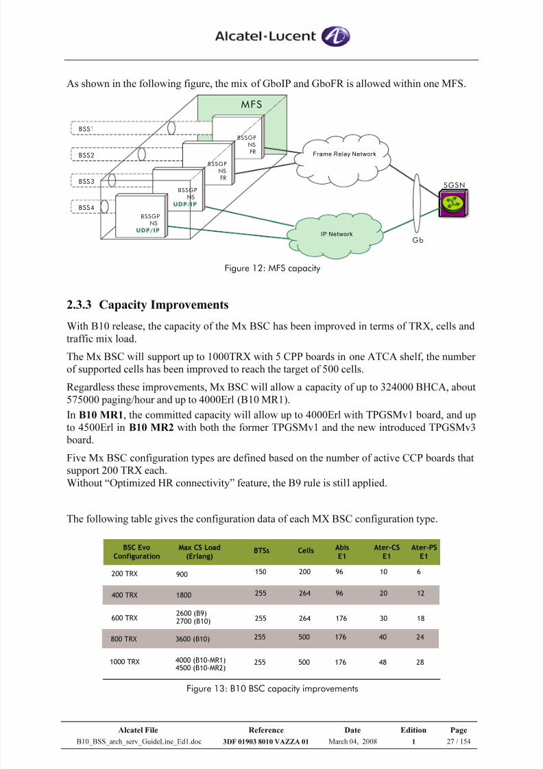
As shown in the following figure, the mix of GboIP and GboFR is allowed within one MFS.
MFS
SGSN
BSS4
BSS3
BSS2
GbIP Network
Frame Relay Network
BSS1
BSSGP
NS
FR
BSSGP
NS
FR
BSSGP
NS
UDP/IP
BSSGP
NS
UDP/IP
Figure 12: MFS capacity
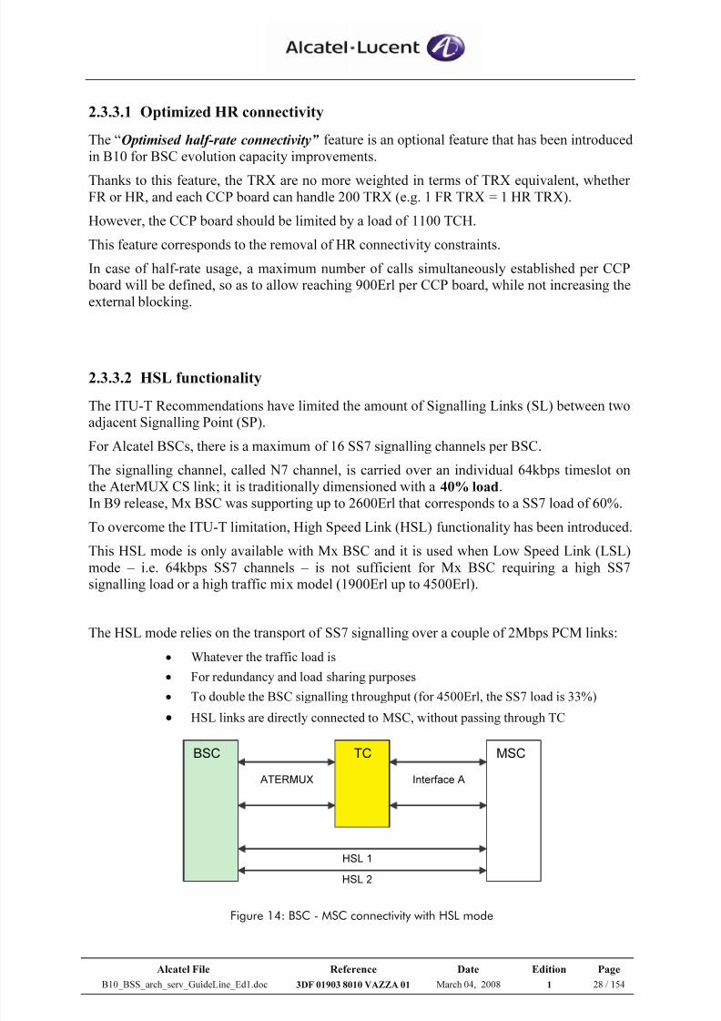
2.3.3 Capacity Improvements
With B10 release, the capacity of the Mx BSC has been improved in terms of TRX, cells and
traffic mix load.
The Mx BSC will support up to 1000TRX with 5 CPP boards in one ATCA shelf, the number
of supported cells has been improved to reach the target of 500 cells.
Regardless these improvements, Mx BSC will allow a capacity of up to 324000 BHCA, about
575000 paging/hour and up to 4000Erl (B10 MR1).In B10 MR1, the committed capacity will allow up to 4000Erl with TPGSMv1 board, and up
to 4500Erl in B10 MR2 with both the former TPGSMv1 and the new introduced TPGSMv3
board.
Five Mx BSC configuration types are defined based on the number of active CCP boards that
support 200 TRX each.
Without “Optimized HR connectivity” feature, the B9 rule is still applied.
The following table gives the configuration data of each MX BSC configuration type.
200 TRX 900
400 TRX 1800
150
600 TRX
BSC EvoConfiguration
Max CS Load(Erlang)
BTSs
2600 (B9)2700 (B10)
255
255
800 TRX 3600 (B10)
1000 TRX 4000 (B10-MR1)4500 (B10-MR2)
255
255
200
Cells
264
264
500
500
96
AbisE1
96
176
176
176
10
Ater-CSE1
20
30
40
48
6
Ater-PSE1
12
18
24
28
Figure 13: B10 BSC capacity improvements
7/21/2019 BSS Architecture Service Guideline B10
http://slidepdf.com/reader/full/bss-architecture-service-guideline-b10 28/154
Alcatel File Reference Date Edition Page
B10_BSS_arch_serv_GuideLine_Ed1.doc 3DF 01903 8010 VAZZA 01 March 04, 2008 1 28 / 154
2.3.3.1 Optimized HR connectivity
The “Optimised half-rate connectivity” feature is an optional feature that has been introduced
in B10 for BSC evolution capacity improvements.
Thanks to this feature, the TRX are no more weighted in terms of TRX equivalent, whetherFR or HR, and each CCP board can handle 200 TRX (e.g. 1 FR TRX = 1 HR TRX).
However, the CCP board should be limited by a load of 1100 TCH.
This feature corresponds to the removal of HR connectivity constraints.
In case of half-rate usage, a maximum number of calls simultaneously established per CCP
board will be defined, so as to allow reaching 900Erl per CCP board, while not increasing the
external blocking.
2.3.3.2 HSL functionality
The ITU-T Recommendations have limited the amount of Signalling Links (SL) between two
adjacent Signalling Point (SP).
For Alcatel BSCs, there is a maximum of 16 SS7 signalling channels per BSC.
The signalling channel, called N7 channel, is carried over an individual 64kbps timeslot on
the AterMUX CS link; it is traditionally dimensioned with a 40% load.
In B9 release, Mx BSC was supporting up to 2600Erl that corresponds to a SS7 load of 60%.
To overcome the ITU-T limitation, High Speed Link (HSL) functionality has been introduced.
This HSL mode is only available with Mx BSC and it is used when Low Speed Link (LSL)
mode – i.e. 64kbps SS7 channels – is not sufficient for Mx BSC requiring a high SS7
signalling load or a high traffic mix model (1900Erl up to 4500Erl).
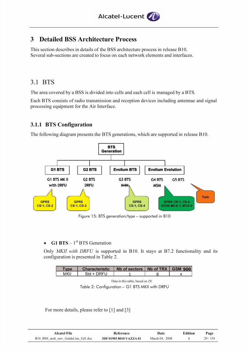
The HSL mode relies on the transport of SS7 signalling over a couple of 2Mbps PCM links:
• Whatever the traffic load is
• For redundancy and load sharing purposes
• To double the BSC signalling throughput (for 4500Erl, the SS7 load is 33%)
• HSL links are directly connected to MSC, without passing through TC
Figure 14: BSC - MSC connectivity with HSL mode
BSC MSCTC
HSL 2
HSL 1
ATERMUX Interface A
7/21/2019 BSS Architecture Service Guideline B10
http://slidepdf.com/reader/full/bss-architecture-service-guideline-b10 29/154
Alcatel File Reference Date Edition Page
B10_BSS_arch_serv_GuideLine_Ed1.doc 3DF 01903 8010 VAZZA 01 March 04, 2008 1 29 / 154
3 Detailed BSS Architecture Process
This section describes in details of the BSS architecture process in release B10.
Several sub-sections are created to focus on each network elements and interfaces.
3.1 BTS
The area covered by a BSS is divided into cells and each cell is managed by a BTS.
Each BTS consists of radio transmission and reception devices including antennae and signal
processing equipment for the Air Interface.
3.1.1 BTS Configuration
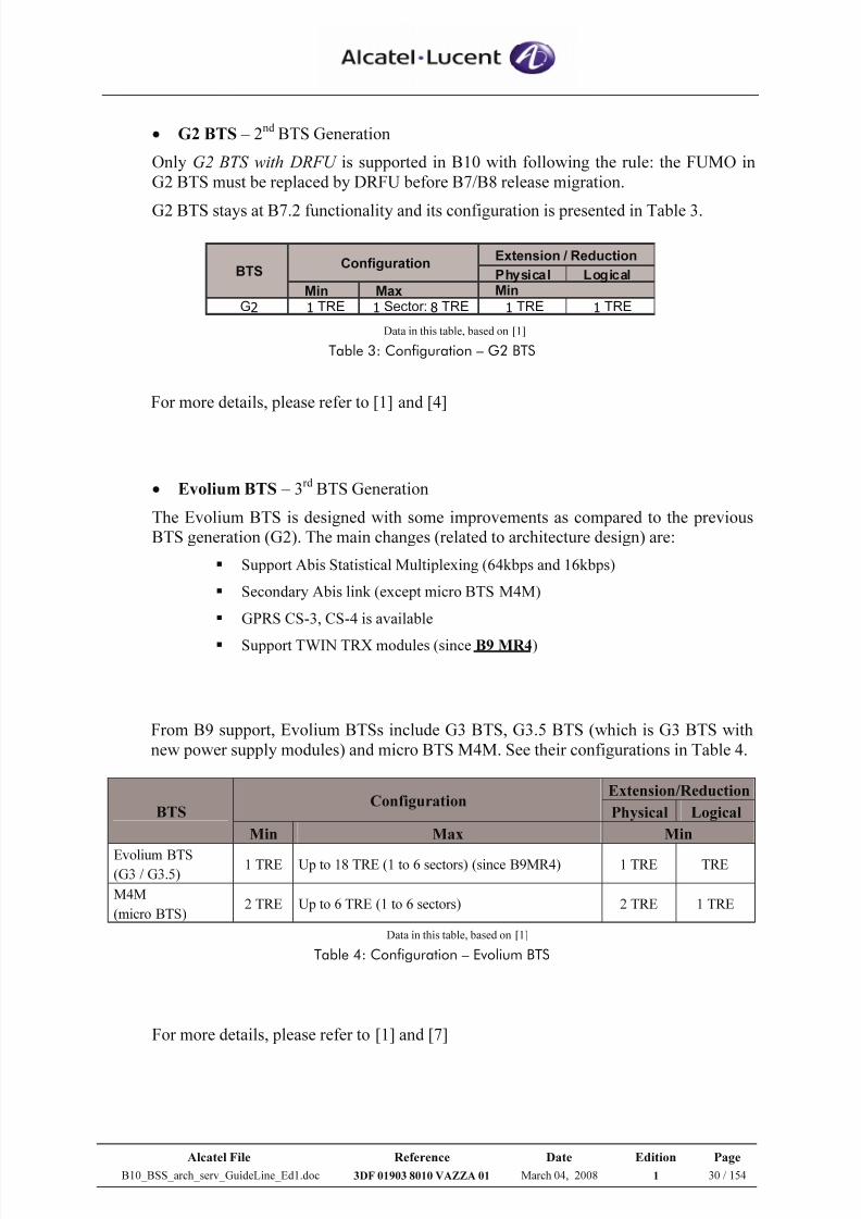
The following diagram presents the BTS generations, which are supported in release B10.
BTS
Generation
Evolium EvolutionG1 BTS G2 BTS Evolium BTS
G1 BTS MK II
with DRFU
G2 BTS
DRFU
G3 BTS
M4M
G4 BTS
M5M
GPRS
CS-1, CS-2
GPRS
CS-1, CS-2
GPRS
CS-1, CS-4
GPRS CS-1, CS-4
EDGE MCS-1, MCS-9
G5 BTS
Twin
BTS
Generation
Evolium EvolutionG1 BTS G2 BTS Evolium BTS
G1 BTS MK II
with DRFU
G2 BTS
DRFU
G3 BTS
M4M
G4 BTS
M5M
BTS
Generation
Evolium EvolutionG1 BTS G2 BTS Evolium BTS
G1 BTS MK II
with DRFU
G2 BTS
DRFU
G3 BTS
M4M
G4 BTS
M5M
GPRS
CS-1, CS-2
GPRS
CS-1, CS-2
GPRS
CS-1, CS-4
GPRS CS-1, CS-4
EDGE MCS-1, MCS-9
G5 BTS
Twin
Figure 15: BTS generation/type – supported in B10
• G1 BTS – 1st BTS Generation
Only MKII with DRFU is supported in B10. It stays at B7.2 functionality and its
configuration is presented in Table 2.
Type Characteristic Nb of sectors Nb of TRX GSM 900
MKII Std + DRFU 1 8 x Data in this table, based on [9]
Table 2: Configuration – G1 BTS MKII with DRFU
For more details, please refer to [1] and [3]
7/21/2019 BSS Architecture Service Guideline B10
http://slidepdf.com/reader/full/bss-architecture-service-guideline-b10 30/154
Alcatel File Reference Date Edition Page
B10_BSS_arch_serv_GuideLine_Ed1.doc 3DF 01903 8010 VAZZA 01 March 04, 2008 1 30 / 154
• G2 BTS – 2nd BTS Generation
Only G2 BTS with DRFU is supported in B10 with following the rule: the FUMO in
G2 BTS must be replaced by DRFU before B7/B8 release migration.
G2 BTS stays at B7.2 functionality and its configuration is presented in Table 3.
Extension / Reduction
Physical Logical
Min MaxG2 1 TRE 1 Sector: 8 TRE 1 TRE 1 TRE
ConfigurationBTS
Min
Data in this table, based on [1]
Table 3: Configuration – G2 BTS
For more details, please refer to [1] and [4]
• Evolium BTS – 3rd BTS Generation
The Evolium BTS is designed with some improvements as compared to the previous
BTS generation (G2). The main changes (related to architecture design) are:
Support Abis Statistical Multiplexing (64kbps and 16kbps)
Secondary Abis link (except micro BTS M4M)
GPRS CS-3, CS-4 is available
Support TWIN TRX modules (since B9 MR4)
From B9 support, Evolium BTSs include G3 BTS, G3.5 BTS (which is G3 BTS with
new power supply modules) and micro BTS M4M. See their configurations in Table 4.
Extension/ReductionConfiguration
Physical LogicalBTS
Min Max Min
Evolium BTS(G3 / G3.5)
1 TRE Up to 18 TRE (1 to 6 sectors) (since B9MR4) 1 TRE TRE
M4M
(micro BTS)2 TRE Up to 6 TRE (1 to 6 sectors) 2 TRE 1 TRE
Data in this table, based on [1]
Table 4: Configuration – Evolium BTS
For more details, please refer to [1] and [7]
7/21/2019 BSS Architecture Service Guideline B10
http://slidepdf.com/reader/full/bss-architecture-service-guideline-b10 31/154
Alcatel File Reference Date Edition Page
B10_BSS_arch_serv_GuideLine_Ed1.doc 3DF 01903 8010 VAZZA 01 March 04, 2008 1 31 / 154
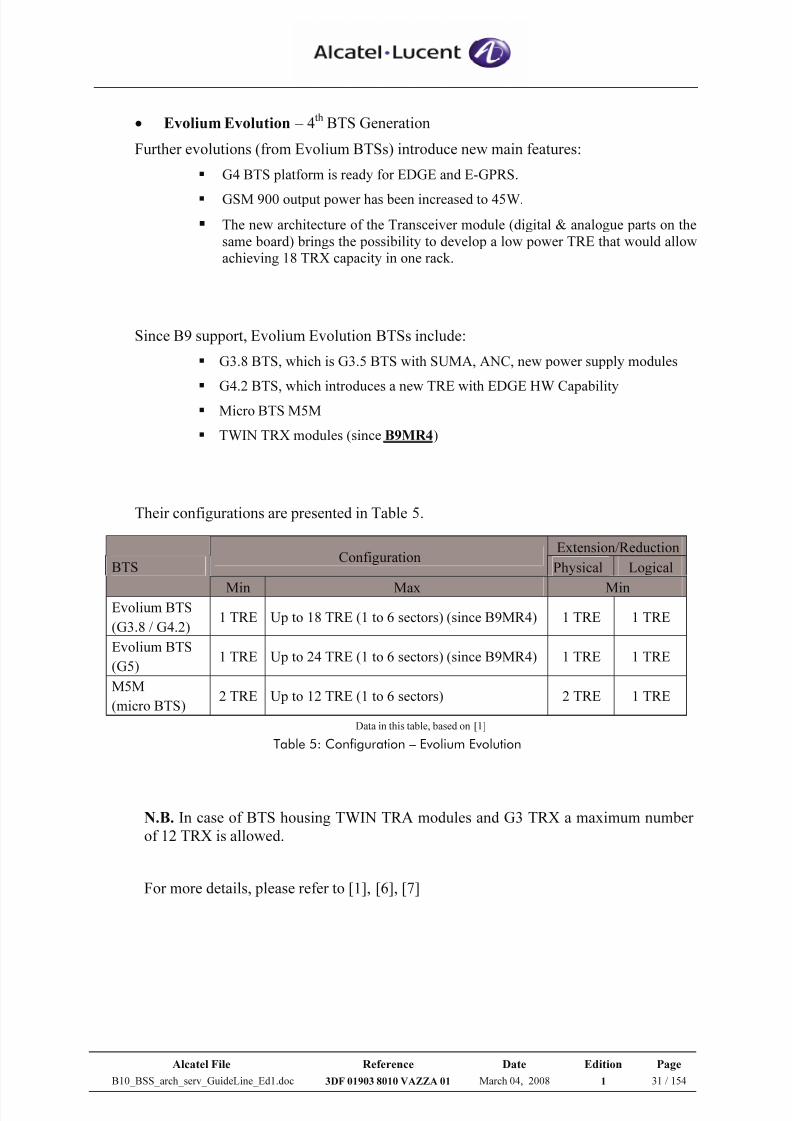
• Evolium Evolution – 4th BTS Generation
Further evolutions (from Evolium BTSs) introduce new main features:
G4 BTS platform is ready for EDGE and E-GPRS.
GSM 900 output power has been increased to 45W.
The new architecture of the Transceiver module (digital & analogue parts on the
same board) brings the possibility to develop a low power TRE that would allow
achieving 18 TRX capacity in one rack.
Since B9 support, Evolium Evolution BTSs include:
G3.8 BTS, which is G3.5 BTS with SUMA, ANC, new power supply modules
G4.2 BTS, which introduces a new TRE with EDGE HW Capability Micro BTS M5M
TWIN TRX modules (since B9MR4)
Their configurations are presented in Table 5.
Extension/ReductionConfiguration
Physical LogicalBTS
Min Max MinEvolium BTS
(G3.8 / G4.2)1 TRE Up to 18 TRE (1 to 6 sectors) (since B9MR4) 1 TRE 1 TRE
Evolium BTS
(G5)1 TRE Up to 24 TRE (1 to 6 sectors) (since B9MR4) 1 TRE 1 TRE
M5M
(micro BTS)2 TRE Up to 12 TRE (1 to 6 sectors) 2 TRE 1 TRE
Data in this table, based on [1]
Table 5: Configuration – Evolium Evolution
N.B. In case of BTS housing TWIN TRA modules and G3 TRX a maximum number
of 12 TRX is allowed.
For more details, please refer to [1], [6], [7]
7/21/2019 BSS Architecture Service Guideline B10
http://slidepdf.com/reader/full/bss-architecture-service-guideline-b10 32/154
Alcatel File Reference Date Edition Page
B10_BSS_arch_serv_GuideLine_Ed1.doc 3DF 01903 8010 VAZZA 01 March 04, 2008 1 32 / 154
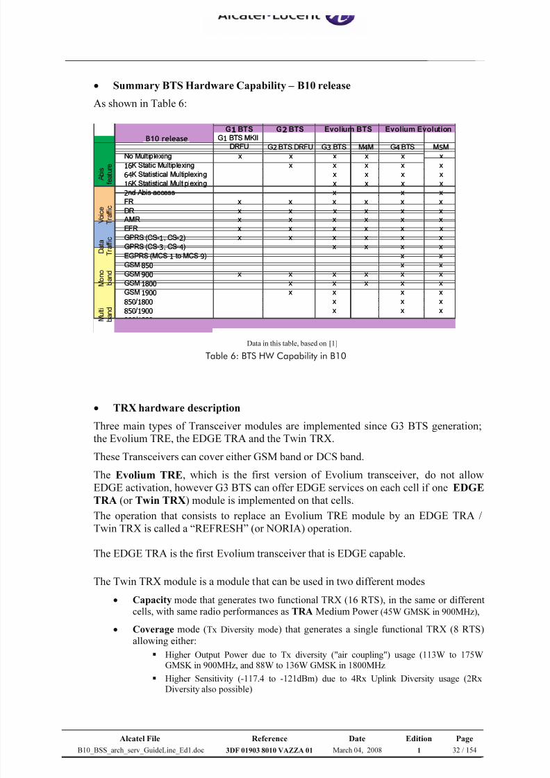
• Summary BTS Hardware Capability – B10 release
As shown in Table 6:
G1BTS G2BTS
G1 BTS MKIIDRFU G2BTS DRFU G3 BTS M4M G4 BTS M5M
No Multiplexing x x x x x x
16K Static Multiplexing x x x x x
64K Statistical Multiplexing x x x x
16K Statistical Multiplexing x x x x
2nd Abis access x x x
FR x x x x x x
DR x x x x x x
AMR x x x x x x
EFR x x x x x x
GPRS (CS-1, CS-2) x x x x x x
GPRS (CS-3, CS-4) x x x x
EGPRS (MCS-1 to MCS-9) x x
GSM 850 x x
GSM 900 x x x x x xGSM 1800 x x x x x
GSM 1900 x x x x
850/ 1800 x x x
850/ 1900 x x x
900/ 1800 x x x x
900/ 1900 x x x
M u l t i
b a n d
Evolium BTS Evolium Evolution
B9 release
A b i s
f e a t u r e
V o i c e
T r a f f i c
D a t a
T r a f f i c
M o n o
b a n d
B10 release
Data in this table, based on [1]
Table 6: BTS HW Capability in B10
• TRX hardware description
Three main types of Transceiver modules are implemented since G3 BTS generation;
the Evolium TRE, the EDGE TRA and the Twin TRX.
These Transceivers can cover either GSM band or DCS band.
The Evolium TRE, which is the first version of Evolium transceiver, do not allow
EDGE activation, however G3 BTS can offer EDGE services on each cell if one EDGE
TRA (or Twin TRX) module is implemented on that cells.
The operation that consists to replace an Evolium TRE module by an EDGE TRA /
Twin TRX is called a “REFRESH” (or NORIA) operation.
The EDGE TRA is the first Evolium transceiver that is EDGE capable.
The Twin TRX module is a module that can be used in two different modes
• Capacity mode that generates two functional TRX (16 RTS), in the same or different
cells, with same radio performances as TRA Medium Power (45W GMSK in 900MHz),
• Coverage mode (Tx Diversity mode) that generates a single functional TRX (8 RTS)
allowing either:
Higher Output Power due to Tx diversity ("air coupling") usage (113W to 175WGMSK in 900MHz, and 88W to 136W GMSK in 1800MHz
Higher Sensitivity (-117.4 to -121dBm) due to 4Rx Uplink Diversity usage (2RxDiversity also possible)
7/21/2019 BSS Architecture Service Guideline B10
http://slidepdf.com/reader/full/bss-architecture-service-guideline-b10 33/154
Alcatel File Reference Date Edition Page
B10_BSS_arch_serv_GuideLine_Ed1.doc 3DF 01903 8010 VAZZA 01 March 04, 2008 1 33 / 154
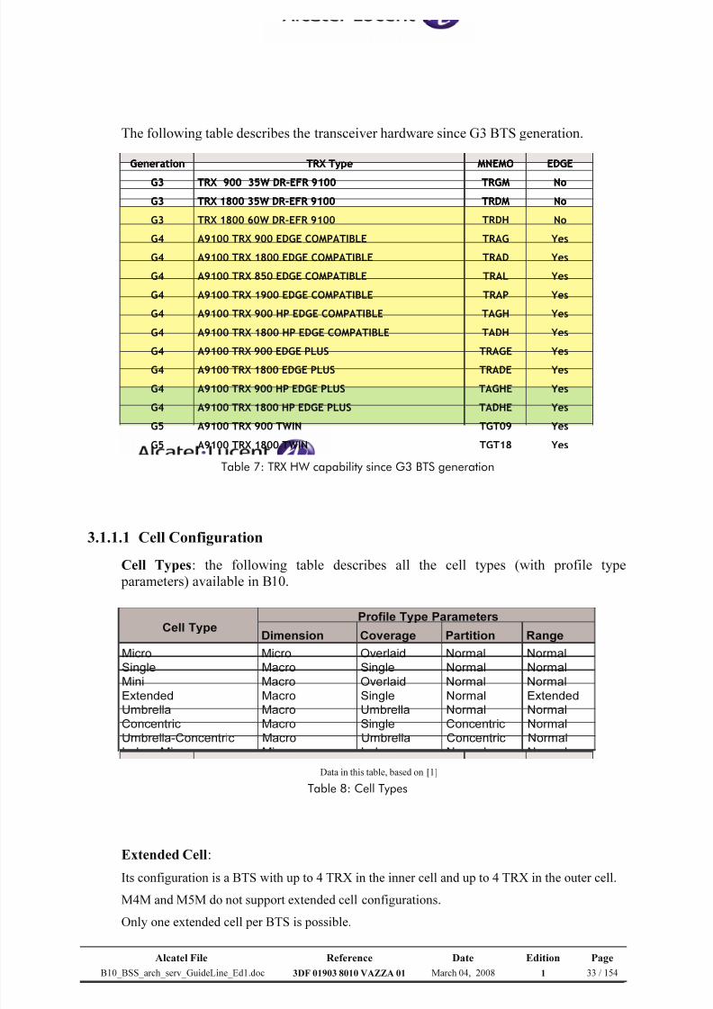
The following table describes the transceiver hardware since G3 BTS generation.
YesTGT18A9100 TRX 1800 TWING5
YesTGT09A9100 TRX 900 TWING5
YesTADHEA9100 TRX 1800 HP EDGE PLUSG4
YesTAGHEA9100 TRX 900 HP EDGE PLUSG4
YesTRADEA9100 TRX 1800 EDGE PLUSG4YesTRAGEA9100 TRX 900 EDGE PLUSG4
YesTADHA9100 TRX 1800 HP EDGE COMPATIBLEG4
YesTAGHA9100 TRX 900 HP EDGE COMPATIBLEG4
YesTRAPA9100 TRX 1900 EDGE COMPATIBLEG4
YesTRALA9100 TRX 850 EDGE COMPATIBLEG4
YesTRADA9100 TRX 1800 EDGE COMPATIBLEG4
YesTRAGA9100 TRX 900 EDGE COMPATIBLEG4
NoTRDHTRX 1800 60W DR-EFR 9100G3
NoTRDMTRX 1800 35W DR-EFR 9100G3
NoTRGMTRX 900 35W DR-EFR 9100G3
EDGEMNEMOTRX TypeGeneration
Table 7: TRX HW capability since G3 BTS generation
3.1.1.1 Cell Configuration
Cell Types: the following table describes all the cell types (with profile type
parameters) available in B10.
Dimension Coverage Partition Range
Micro Micro Overlaid Normal Normal
Single Macro Single Normal Normal
Mini Macro Overlaid Normal Normal
Extended Macro Single Normal Extended
Umbrella Macro Umbrella Normal NormalConcentric Macro Single Concentric Normal
Umbrella-Concentric Macro Umbrella Concentric Normal
Indoor Micro Micro Indoor Normal Normal
Profile Type ParametersCell Type
Data in this table, based on [1]
Table 8: Cell Types
Extended Cell:
Its configuration is a BTS with up to 4 TRX in the inner cell and up to 4 TRX in the outer cell.M4M and M5M do not support extended cell configurations.
Only one extended cell per BTS is possible.
7/21/2019 BSS Architecture Service Guideline B10
http://slidepdf.com/reader/full/bss-architecture-service-guideline-b10 34/154
Alcatel File Reference Date Edition Page
B10_BSS_arch_serv_GuideLine_Ed1.doc 3DF 01903 8010 VAZZA 01 March 04, 2008 1 34 / 154
Shared Cell:
A cell shared by several BTSs is possible to support up to 16 TRX (software limitation).
With Twin TRX, the 16 TRX limitation can be reached without using shared cell method.
Only the A9100 Evolium BTS (G3 BTS & G4 BTS) support shared cell.
The BTSs in a shared cell must be clock synchronized.
M4M and M5M do not support a shared cell because they cannot be clock synchronized.
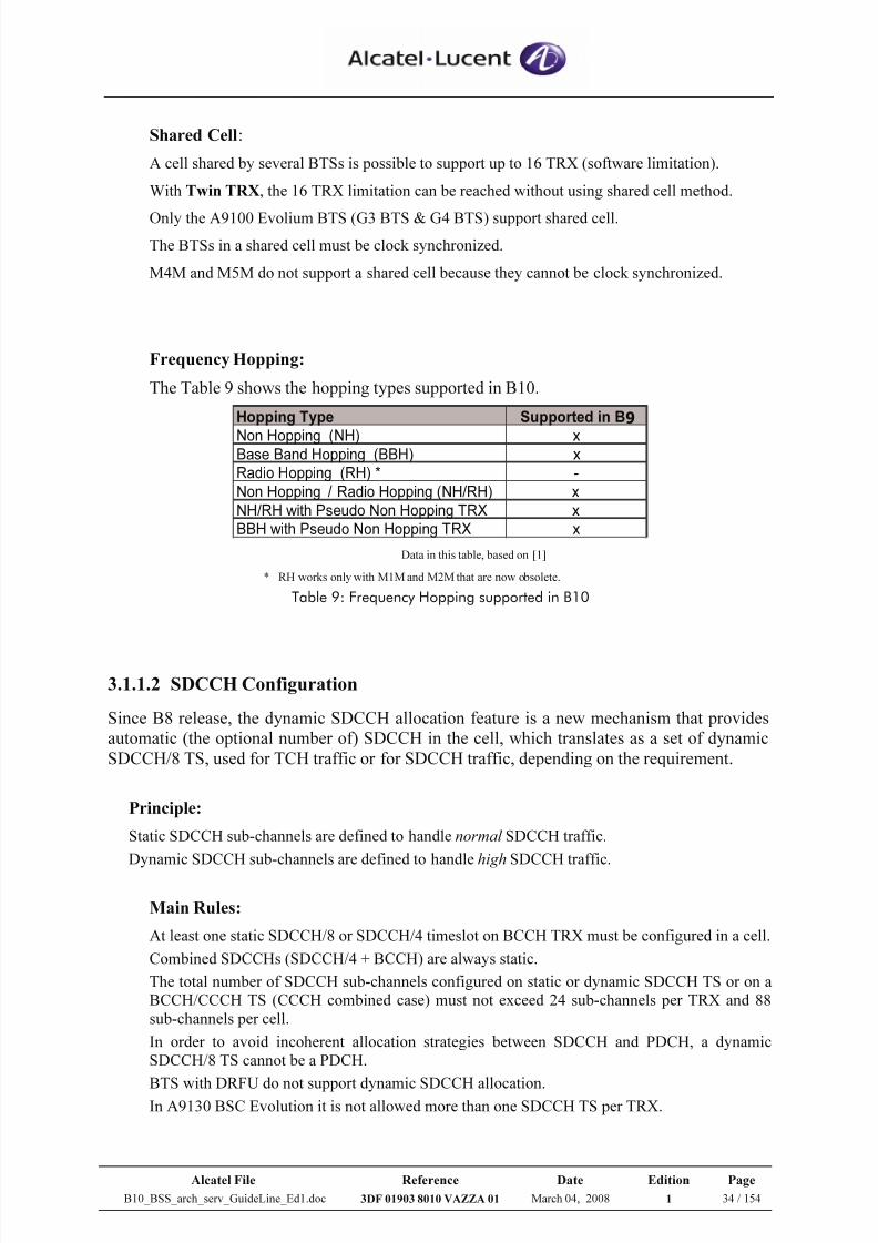
Frequency Hopping:
The Table 9 shows the hopping types supported in B10.
Hopping Type Supported in B9
Non Hopping (NH) xBase Band Hopping (BBH) x
Radio Hopping (RH) * -
Non Hopping / Radio Hopping (NH/RH) x
NH/RH with Pseudo Non Hopping TRX x
BBH with Pseudo Non Hopping TRX x Data in this table, based on [1]
* RH works only with M1M and M2M that are now obsolete.
Table 9: Frequency Hopping supported in B10
3.1.1.2 SDCCH Configuration
Since B8 release, the dynamic SDCCH allocation feature is a new mechanism that provides
automatic (the optional number of) SDCCH in the cell, which translates as a set of dynamic
SDCCH/8 TS, used for TCH traffic or for SDCCH traffic, depending on the requirement.
Principle:
Static SDCCH sub-channels are defined to handle normal SDCCH traffic.
Dynamic SDCCH sub-channels are defined to handle high SDCCH traffic.
Main Rules:
At least one static SDCCH/8 or SDCCH/4 timeslot on BCCH TRX must be configured in a cell.
Combined SDCCHs (SDCCH/4 + BCCH) are always static.
The total number of SDCCH sub-channels configured on static or dynamic SDCCH TS or on a
BCCH/CCCH TS (CCCH combined case) must not exceed 24 sub-channels per TRX and 88
sub-channels per cell.
In order to avoid incoherent allocation strategies between SDCCH and PDCH, a dynamic
SDCCH/8 TS cannot be a PDCH.
BTS with DRFU do not support dynamic SDCCH allocation.In A9130 BSC Evolution it is not allowed more than one SDCCH TS per TRX.
7/21/2019 BSS Architecture Service Guideline B10
http://slidepdf.com/reader/full/bss-architecture-service-guideline-b10 35/154
Alcatel File Reference Date Edition Page
B10_BSS_arch_serv_GuideLine_Ed1.doc 3DF 01903 8010 VAZZA 01 March 04, 2008 1 35 / 154
Recommended SDCCH configuration:
In a cell, the number of SDCCHs is defined variously, based on:
- Location Update (LU) signalling traffic: 1 LU/call for standard cell
- SMS signalling traffic: 0.5 SMS/call for standard cell- Number of TRXs
Recommended default number of SDCCH and configuration are presented in Table 10.
Total SDC SDD
1 Yes 12 4 8
2 Yes 12 4 8
2 No 24 8 16
3 No 24 8 164 No 32 8 24
5 No 32 8 24
6 No 32 8 24
7 No 40 16 24
8 No 40 16 24
9 No 48 16 32
10 No 48 16 32
11 No 48 16 32
12 No 56 16 40
13 No 56 16 40
14 No 64 24 40
15 No 72 24 48
16 No 72 24 48
Number of TRXs BCCH CombinedNumber of SDCCH sub-channels
Data in this table, based on [8]
Table 10: Recommended SDCCH configuration for a standard cell – only FR TRXs
Remarks:
1) SDC means Static SDCCH, SDD means Dynamic SDCCH, and Max presents the
maximum number of SDCCHs (SDC+SDD) that may be allocated in a cell.
2) Up to 16 TRXs are possible to be configured for a cell – thanks to shared cell feature.
3) For one TRX, dynamic SDCCH are over-dimensioned because of the granularity of 8.
According to Alcatel traffic model, all dynamic SDCCH will not be used.4) An additional dynamic SDCCH/8 must be provided for each DR TRX (these are
expected mainly on small cells).
5) For some particular cells with high (LU and/or SMS) signalling load, the operator will
probably need to customize the number of SDCCHs (different from the
recommendation) according to his requirements; otherwise the SDCCH dimensioning
should be applied (please refer to section 3.1.3.1).
For more details, please refer to [1] and [8]
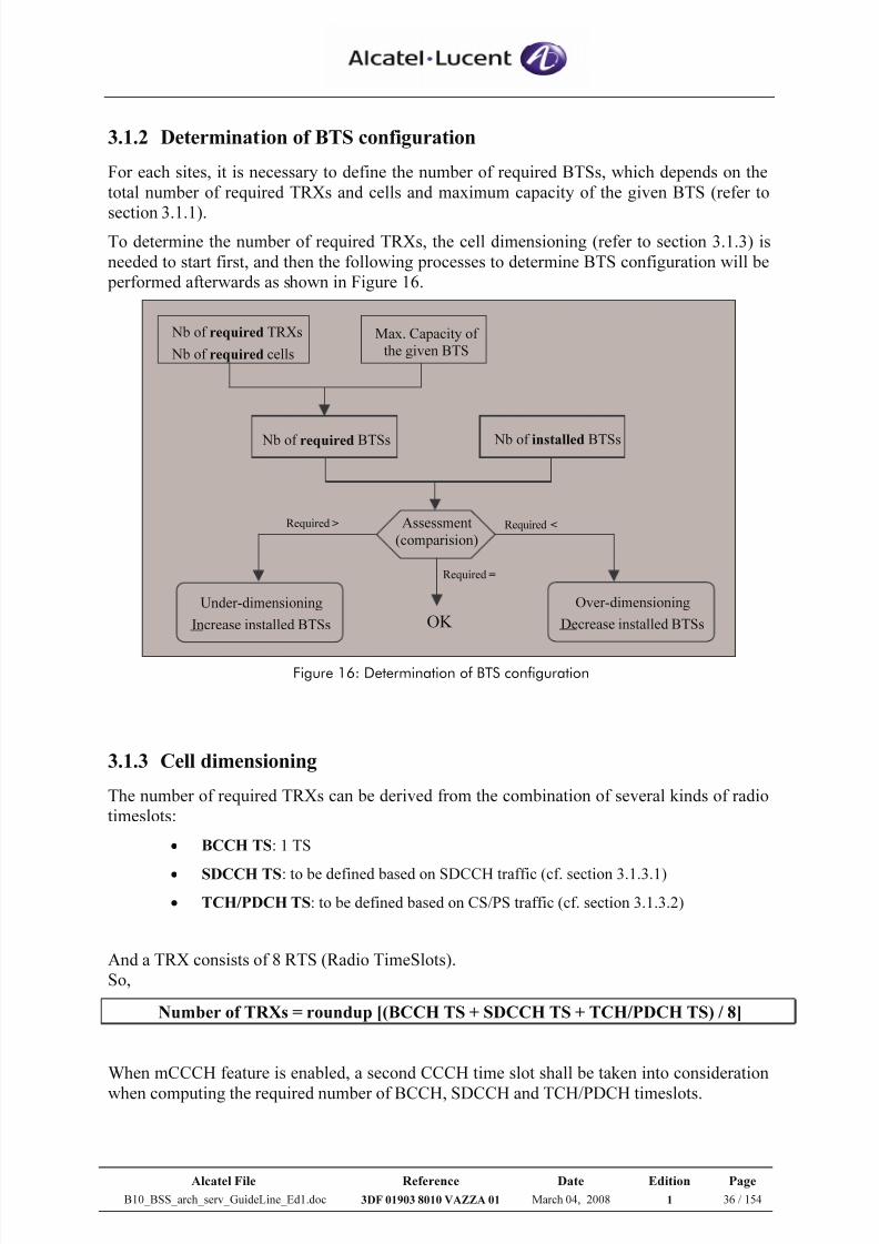
7/21/2019 BSS Architecture Service Guideline B10
http://slidepdf.com/reader/full/bss-architecture-service-guideline-b10 36/154
Alcatel File Reference Date Edition Page
B10_BSS_arch_serv_GuideLine_Ed1.doc 3DF 01903 8010 VAZZA 01 March 04, 2008 1 36 / 154
3.1.2 Determination of BTS configuration
For each sites, it is necessary to define the number of required BTSs, which depends on the
total number of required TRXs and cells and maximum capacity of the given BTS (refer to
section 3.1.1).To determine the number of required TRXs, the cell dimensioning (refer to section 3.1.3) is
needed to start first, and then the following processes to determine BTS configuration will be
performed afterwards as shown in Figure 16.
Nb of required TRXs
Nb of required cells
Max. Capacity of
the given BTS
Assessment
(comparision)
OK
Under-dimensioning
Increase installed BTSs
Required >
Required =
Required <
Over-dimensioning
Decrease installed BTSs
Nb of installed BTSs Nb of required BTSs
Figure 16: Determination of BTS configuration
3.1.3 Cell dimensioning
The number of required TRXs can be derived from the combination of several kinds of radio
timeslots:
• BCCH TS: 1 TS
• SDCCH TS: to be defined based on SDCCH traffic (cf. section 3.1.3.1)
• TCH/PDCH TS: to be defined based on CS/PS traffic (cf. section 3.1.3.2)
And a TRX consists of 8 RTS (Radio TimeSlots).
So,
Number of TRXs = roundup [(BCCH TS + SDCCH TS + TCH/PDCH TS) / 8]
When mCCCH feature is enabled, a second CCCH time slot shall be taken into consideration
when computing the required number of BCCH, SDCCH and TCH/PDCH timeslots.
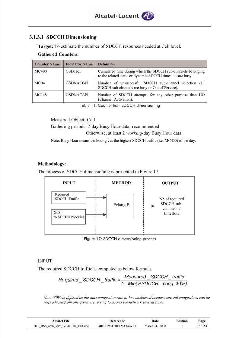
7/21/2019 BSS Architecture Service Guideline B10
http://slidepdf.com/reader/full/bss-architecture-service-guideline-b10 37/154
Alcatel File Reference Date Edition Page
B10_BSS_arch_serv_GuideLine_Ed1.doc 3DF 01903 8010 VAZZA 01 March 04, 2008 1 37 / 154
3.1.3.1 SDCCH Dimensioning
Target: To estimate the number of SDCCH resources needed at Cell level.
Gathered Counters:
Counter Name Indicator Name Definition
MC400 GSDTRT Cumulated time during which the SDCCH sub-channels belongingto the related static or dynamic SDCCH timeslots are busy.
MC04 GSDNACGN Number of unsuccessful SDCCH sub-channel selection (allSDCCH sub-channels are busy or Out of Service).
MC148 GSDNACAN Number of SDCCH attempts for any other purpose than HO(Channel Activation).
Table 11: Counter list - SDCCH dimensioning
Measured Object: Cell
Gathering periods: 7-day Busy Hour data, recommended
Otherwise, at least 2 working -day Busy Hour data
Note: Busy Hour means the hour gives the highest SDCCH traffic (i.e. MC400) of the day.
Methodology:
The process of SDCCH dimensioning is presented in Figure 17.
Erlang B
Required
SDCCH Traffic
GoS:
% SDCCH blocking
Nb of required
SDCCH sub-
channels /
timeslots
INPUT OUTPUTMETHOD
Figure 17: SDCCH dimensioning process
INPUT
The required SDCCH traffic is computed as below formula.
%),cong _SDCCH (%Min
traffic _SDCCH _Measured traffic _SDCCH _quired Re
301−=
Note: 30% is defined as the max congestion rate to be considered because several congestions can bere-produced from one given user trying to access the network several times.
7/21/2019 BSS Architecture Service Guideline B10
http://slidepdf.com/reader/full/bss-architecture-service-guideline-b10 38/154
Alcatel File Reference Date Edition Page
B10_BSS_arch_serv_GuideLine_Ed1.doc 3DF 01903 8010 VAZZA 01 March 04, 2008 1 38 / 154
Where:
3600
400 _ _
MC trafficSDCCH Measured =
%10014804
04 _ % ×
+
=
MC MC MC cong SDCCH
The other input is Grade of Service (GoS), which is defined by the required SDCCH
congestion rate (pSDCCH).
Normally GoS should be given or agreed by the Mobile Operator.
The typical value for the required SDCCH congestion rate is 0.5%.
METHOD
Concerning only CS traffic, the statistical law Erlang B is used during the dimensioning
process to determine the necessary resources versus the traffic and the target GoS.
As SDCCH is associated to CS traffic only, Erlang B can be applied to calculate the
required number of SDCCH sub-channels according to required SDCCH traffic and the
target congestion rate.
OUTPUT
Number of required SDCCH sub-channels
= Erlang B (Required_SDCCH_traffic, pSDCCH)
Then,
Number of required SDCCH Timeslots
Nb of required SDCCH sub-channels / 8; for non- BCCH combined cell
(Nb of required SDCCH sub-channels – 4) / 8; for BCCH combined cell
Assessment:
When % SDCCH congestion (of any cell) > pSDCCH, the SDCCH re-dimensioning is
needed.
=
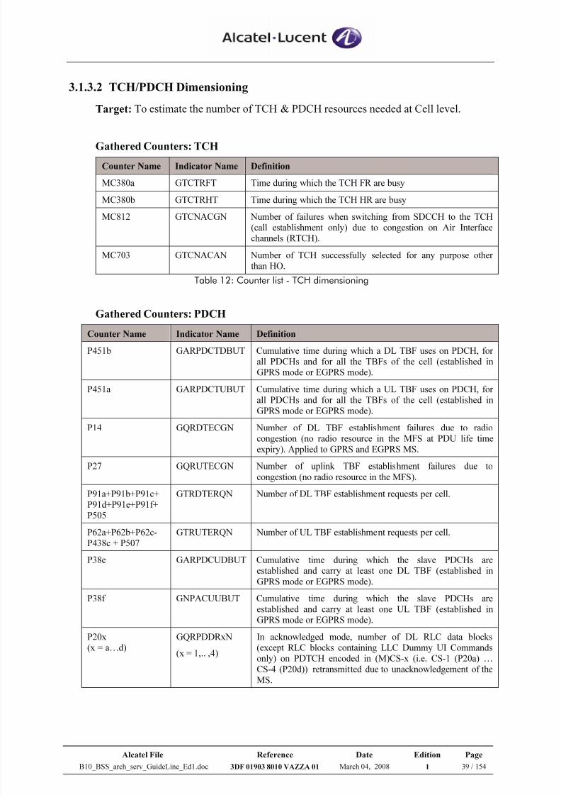
7/21/2019 BSS Architecture Service Guideline B10
http://slidepdf.com/reader/full/bss-architecture-service-guideline-b10 39/154
Alcatel File Reference Date Edition Page
B10_BSS_arch_serv_GuideLine_Ed1.doc 3DF 01903 8010 VAZZA 01 March 04, 2008 1 39 / 154
3.1.3.2 TCH/PDCH Dimensioning
Target: To estimate the number of TCH & PDCH resources needed at Cell level.
Gathered Counters: TCH
Counter Name Indicator Name Definition
MC380a GTCTRFT Time during which the TCH FR are busy
MC380b GTCTRHT Time during which the TCH HR are busy
MC812 GTCNACGN Number of failures when switching from SDCCH to the TCH(call establishment only) due to congestion on Air Interfacechannels (RTCH).
MC703 GTCNACAN Number of TCH successfully selected for any purpose otherthan HO.
Table 12: Counter list - TCH dimensioning
Gathered Counters: PDCH
Counter Name Indicator Name Definition
P451b GARPDCTDBUT Cumulative time during which a DL TBF uses on PDCH, forall PDCHs and for all the TBFs of the cell (established inGPRS mode or EGPRS mode).
P451a GARPDCTUBUT Cumulative time during which a UL TBF uses on PDCH, forall PDCHs and for all the TBFs of the cell (established inGPRS mode or EGPRS mode).
P14 GQRDTECGN Number of DL TBF establishment failures due to radiocongestion (no radio resource in the MFS at PDU life timeexpiry). Applied to GPRS and EGPRS MS.
P27 GQRUTECGN Number of uplink TBF establishment failures due to
congestion (no radio resource in the MFS).
P91a+P91b+P91c+P91d+P91e+P91f+P505
GTRDTERQN Number of DL TBF establishment requests per cell.
P62a+P62b+P62c-P438c + P507
GTRUTERQN Number of UL TBF establishment requests per cell.
P38e GARPDCUDBUT Cumulative time during which the slave PDCHs areestablished and carry at least one DL TBF (established in
GPRS mode or EGPRS mode).
P38f GNPACUUBUT Cumulative time during which the slave PDCHs areestablished and carry at least one UL TBF (established inGPRS mode or EGPRS mode).
P20x(x = a…d)
GQRPDDRxN
(x = 1,.. ,4)
In acknowledged mode, number of DL RLC data blocks(except RLC blocks containing LLC Dummy UI Commandsonly) on PDTCH encoded in (M)CS-x (i.e. CS-1 (P20a) …CS-4 (P20d)) retransmitted due to unacknowledgement of the
MS.
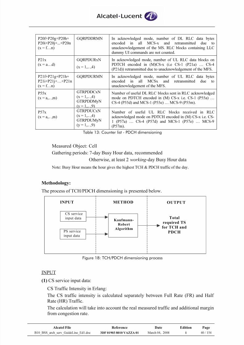
7/21/2019 BSS Architecture Service Guideline B10
http://slidepdf.com/reader/full/bss-architecture-service-guideline-b10 40/154
Alcatel File Reference Date Edition Page
B10_BSS_arch_serv_GuideLine_Ed1.doc 3DF 01903 8010 VAZZA 01 March 04, 2008 1 40 / 154
P20f+P20g+P20h+P20i+P20j+...+P20n
(x = f…n)
GQRPDDRMN In acknowledged mode, number of DL RLC data bytesencoded in all MCS-x and retransmitted due to
unacknowledgement of the MS. RLC blocks containing LLCdummy UI commands are not counted.
P21x(x = a…d)
GQRPDURxN
(x = 1,.. ,4)
In acknowledged mode, number of UL RLC data blocks onPDTCH encoded in (M)CS-x (i.e CS-1 (P21a) … CS-4
(P21d)) retransmitted due to unacknowledgement of the MFS.
P21f+P21g+P21h+P21i+P21j+…+P21n(x = f…n)
GQRPDURMN In acknowledged mode, number of UL RLC data bytesencoded in all MCSx and retransmitted due tounacknowledgement of the MFS.
P55x(x = a,.. ,m)
GTRPDDCxN(x = 1,.. ,4)GTRPDDMyN
(y = 1,.. ,9)
Number of useful DL RLC blocks sent in RLC acknowledgedmode on PDTCH encoded in (M) CS-x i.e. CS-1 (P55a) …CS-4 (P55d) and MCS-1 (P55e) … MCS-9 (P55m).
P57x
(x = a,.. ,m)
GTRPDUCxN
(x = 1,.. ,4)
GTRPDUMyN(y = 1,.. ,9)
Number of useful UL RLC blocks received in RLC
acknowledged mode on PDTCH encoded in (M) CS-x i.e. CS-
1 (P57a) … CS-4 (P57d) and MCS-1 (P57e) … MCS-9(P57m).
Table 13: Counter list - PDCH dimensioning
Measured Object: Cell
Gathering periods: 7-day Busy Hour data, recommended
Otherwise, at least 2 working -day Busy Hour data
Note: Busy Hour means the hour gives the highest TCH & PDCH traffic of the day.
Methodology:
The process of TCH/PDCH dimensioning is presented below.
Kaufmann-
Robert
Algorithm
CS service
input data
PS service
input data
Total
required TS
for TCH and
PDCH
INPUT OUTPUTMETHOD
Figure 18: TCH/PDCH dimensioning process
INPUT
(1) CS service input data:
CS Traffic Intensity in Erlang:
The CS traffic intensity is calculated separately between Full Rate (FR) and Half
Rate (HR) Traffic.The calculation will take into account the real measured traffic and additional margin
from congestion rate.
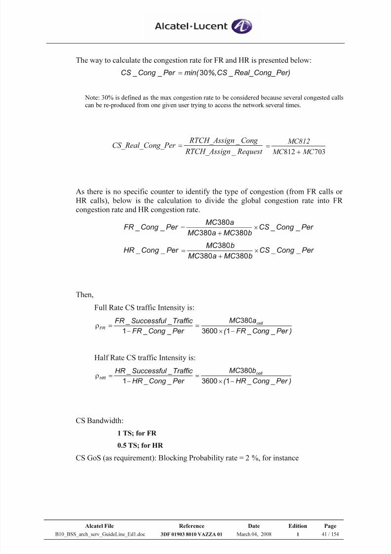
7/21/2019 BSS Architecture Service Guideline B10
http://slidepdf.com/reader/full/bss-architecture-service-guideline-b10 41/154
Alcatel File Reference Date Edition Page
B10_BSS_arch_serv_GuideLine_Ed1.doc 3DF 01903 8010 VAZZA 01 March 04, 2008 1 41 / 154
The way to calculate the congestion rate for FR and HR is presented below:
Per)Real_Cong_ _CS %,min( Per _Cong _CS 30=
Note: 30% is defined as the max congestion rate to be considered because several congested callscan be re-produced from one given user trying to access the network several times.
Request n RTCH_Assig
Cong n RTCH_Assig ng_Per CS_Real_Co
_
_
=
703812 MC MC
MC812
+
=
As there is no specific counter to identify the type of congestion (from FR calls orHR calls), below is the calculation to divide the global congestion rate into FR
congestion rate and HR congestion rate.
Per _Cong _CS bMC aMC
aMC Per _Cong _FR ×
+
=
380380
380
Per _Cong _CS bMC aMC
bMC Per _Cong _HR ×
+
=
380380
380
Then,
Full Rate CS traffic Intensity is:
)Per _Cong _FR (
aMC
Per _Cong _FR
Traffic _Successful _FR cell
FR
−×=
−=ρ
13600
380
1
Half Rate CS traffic Intensity is:
)Per _Cong _HR (
bMC
Per _Cong _HR
Traffic _Successful _HR cell
HR −×
=−
=ρ13600
380
1
CS Bandwidth:
1 TS; for FR
0.5 TS; for HR
CS GoS (as requirement): Blocking Probability rate = 2 %, for instance
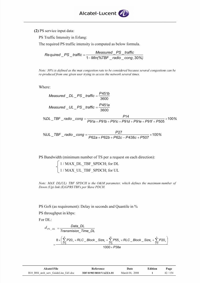
7/21/2019 BSS Architecture Service Guideline B10
http://slidepdf.com/reader/full/bss-architecture-service-guideline-b10 42/154
Alcatel File Reference Date Edition Page
B10_BSS_arch_serv_GuideLine_Ed1.doc 3DF 01903 8010 VAZZA 01 March 04, 2008 1 42 / 154
(2) PS service input data:
PS Traffic Intensity in Erlang:
The required PS traffic intensity is computed as below formula.
%),cong _radio _TBF (%Min
traffic _PS _Measured traffic _PS _quired Re
301−=
Note: 30% is defined as the max congestion rate to be considered because several congestions can bere-produced from one given user trying to access the network several times.
Where:
3600
451bP traffic _PS _DL _Measured =
3600
451aP traffic _PS _UL _Measured =
%P f P eP d P c P bP aP
P cong _radio _TBF _DL% 100
505919191919191
14×
++++++
=
%P c P c P bP aP
P cong _radio _TBF _UL% 100
507438626262
27×
+−++
=
PS Bandwidth (minimum number of TS per a request on each direction):
1 / MAX_DL_TBF_SPDCH; for DL
1 / MAX_UL_TBF_SPDCH; for UL
Note: MAX_DL(UL)_TBF_SPDCH is the O&M parameter, which defines the maximum number of
Down (Up) link (E)GPRS TBFs per Slave PDCH.
PS GoS (as requirement): Delay in seconds and Quantile in %
PS throughput in kbps:
For DL:
DL PS d
_
n_Time_DLTransmisio
Data_DL=
eP
P Size _Block _RLC P Size _Block _RLC P n
f x
x
m
a x
x x
d
a x
x x
381000
2055208
×
+×+××
=∑∑∑===
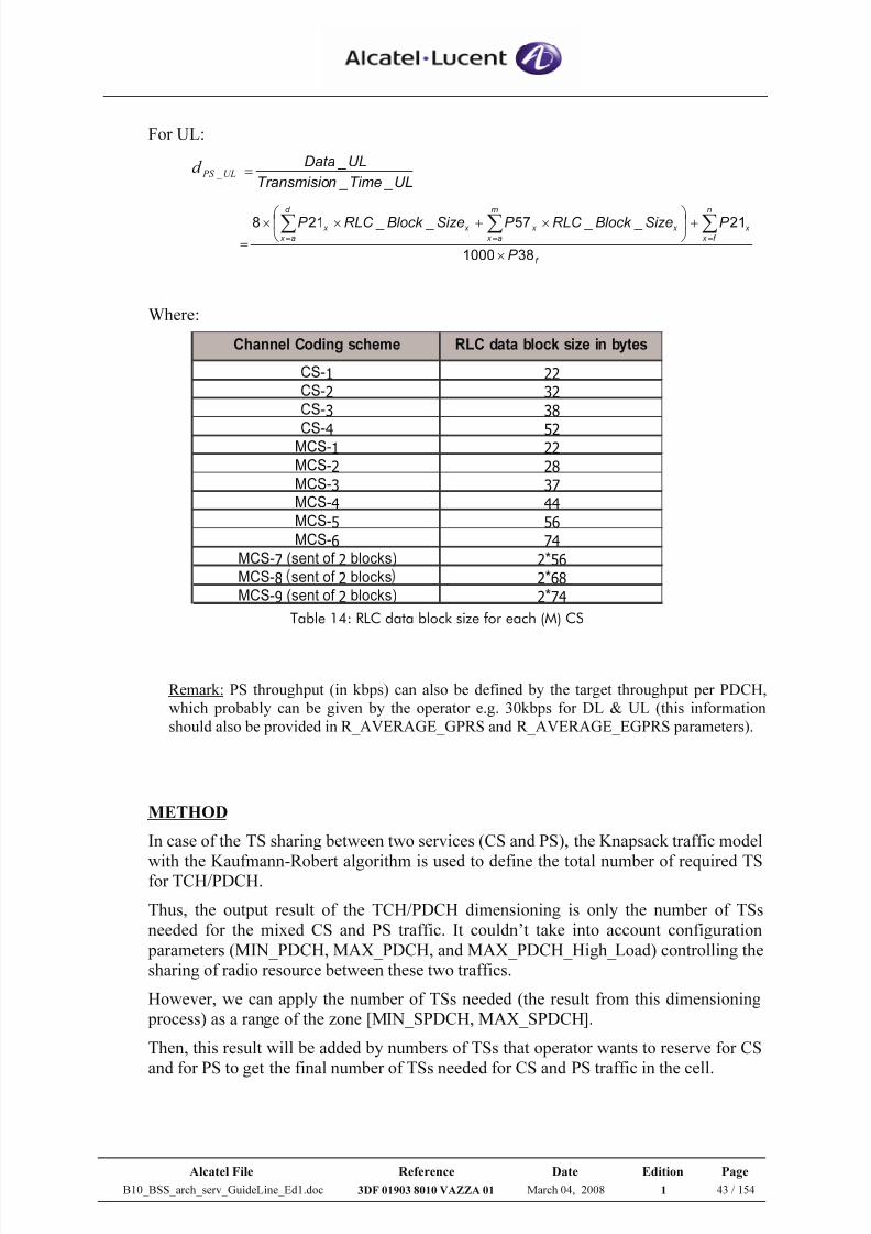
7/21/2019 BSS Architecture Service Guideline B10
http://slidepdf.com/reader/full/bss-architecture-service-guideline-b10 43/154
Alcatel File Reference Date Edition Page
B10_BSS_arch_serv_GuideLine_Ed1.doc 3DF 01903 8010 VAZZA 01 March 04, 2008 1 43 / 154
For UL:
UL PS d
_
UL _Time _nTransmisio
UL _Data=
f
n
f x
x
m
a x
x x
d
a x
x x
P
P Size _Block _RLC P Size _Block _RLC P
381000
2157218
×
+
×+××
=∑∑∑===
Where:
Channel Coding scheme RLC data block size in bytes
CS-1 22
CS-2 32
CS-3 38
CS-4 52MCS-1 22
MCS-2 28
MCS-3 37
MCS-4 44
MCS-5 56
MCS-6 74
MCS-7 (sent of 2 blocks) 2*56MCS-8 sent of 2 blocks 2*68MCS-9 (sent of 2 blocks) 2*74
Table 14: RLC data block size for each (M) CS
Remark: PS throughput (in kbps) can also be defined by the target throughput per PDCH,
which probably can be given by the operator e.g. 30kbps for DL & UL (this information
should also be provided in R_AVERAGE_GPRS and R_AVERAGE_EGPRS parameters).
METHOD
In case of the TS sharing between two services (CS and PS), the Knapsack traffic model
with the Kaufmann-Robert algorithm is used to define the total number of required TSfor TCH/PDCH.
Thus, the output result of the TCH/PDCH dimensioning is only the number of TSs
needed for the mixed CS and PS traffic. It couldn’t take into account configuration
parameters (MIN_PDCH, MAX_PDCH, and MAX_PDCH_High_Load) controlling the
sharing of radio resource between these two traffics.
However, we can apply the number of TSs needed (the result from this dimensioning
process) as a range of the zone [MIN_SPDCH, MAX_SPDCH].
Then, this result will be added by numbers of TSs that operator wants to reserve for CS
and for PS to get the final number of TSs needed for CS and PS traffic in the cell.
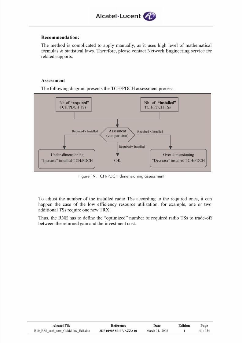
7/21/2019 BSS Architecture Service Guideline B10
http://slidepdf.com/reader/full/bss-architecture-service-guideline-b10 44/154
Alcatel File Reference Date Edition Page
B10_BSS_arch_serv_GuideLine_Ed1.doc 3DF 01903 8010 VAZZA 01 March 04, 2008 1 44 / 154
Recommendation:
The method is complicated to apply manually, as it uses high level of mathematical
formulas & statistical laws. Therefore, please contact Network Engineering service for
related supports.
Assessment
The following diagram presents the TCH/PDCH assessment process.
Nb of “required”
TCH/PDCH TSs
Nb of “installed”
TCH/PDCH TSs
Assesment
(comparision)
OK
Under-dimensioning
“Increase” installed TCH/PDCH
Required > Installed
Required = Installed
Required < Installed
Over-dimensioning
“Decrease” installed TCH/PDCH
Figure 19: TCH/PDCH dimensioning assessment
To adjust the number of the installed radio TSs according to the required ones, it can
happen the case of the low efficiency resource utilization, for example, one or two
additional TSs require one new TRX!
Thus, the RNE has to define the “optimized” number of required radio TSs to trade-off
between the returned gain and the investment cost.
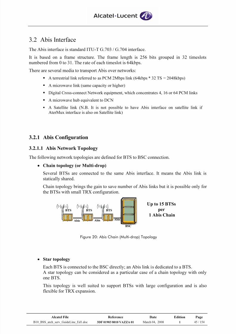
7/21/2019 BSS Architecture Service Guideline B10
http://slidepdf.com/reader/full/bss-architecture-service-guideline-b10 45/154
Alcatel File Reference Date Edition Page
B10_BSS_arch_serv_GuideLine_Ed1.doc 3DF 01903 8010 VAZZA 01 March 04, 2008 1 45 / 154
3.2 Abis Interface
The Abis interface is standard ITU-T G.703 / G.704 interface.
It is based on a frame structure. The frame length is 256 bits grouped in 32 timeslotsnumbered from 0 to 31. The rate of each timeslot is 64kbps.
There are several media to transport Abis over networks:
A terrestrial link referred to as PCM 2Mbps link (64kbps * 32 TS = 2048kbps)
A microwave link (same capacity or higher)
Digital Cross-connect Network equipment, which concentrates 4, 16 or 64 PCM links
A microwave hub equivalent to DCN
A Satellite link (N.B. It is not possible to have Abis interface on satellite link if
AterMux interface is also on Satellite link)
3.2.1 Abis Configuration
3.2.1.1 Abis Network Topology
The following network topologies are defined for BTS to BSC connection.
• Chain topology (or Multi-drop)
Several BTSs are connected to the same Abis interface. It means the Abis link isstatically shared.
Chain topology brings the gain to save number of Abis links but it is possible only for
the BTSs with small TRX configuration.
BSC
BTS
Abis Abis Abis
BTS BTS
Up to 15 BTSs
per
1 Abis Chain
Figure 20: Abis Chain (Multi-drop) Topology
• Star topology
Each BTS is connected to the BSC directly; an Abis link is dedicated to a BTS.
A star topology can be considered as a particular case of a chain topology with only
one BTS.
This topology is well suited to support BTSs with large configuration and is also
flexible for TRX expansion.
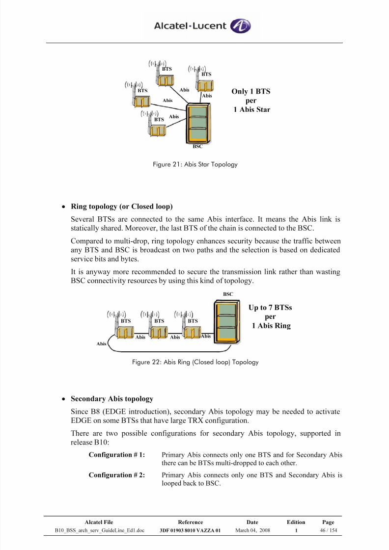
7/21/2019 BSS Architecture Service Guideline B10
http://slidepdf.com/reader/full/bss-architecture-service-guideline-b10 46/154
Alcatel File Reference Date Edition Page
B10_BSS_arch_serv_GuideLine_Ed1.doc 3DF 01903 8010 VAZZA 01 March 04, 2008 1 46 / 154
BTS
BTS
BTS
BTS
Abis
Abis
Abis
Abis
BSC
Only 1 BTS
per
1 Abis Star
Figure 21: Abis Star Topology
• Ring topology (or Closed loop)
Several BTSs are connected to the same Abis interface. It means the Abis link is
statically shared. Moreover, the last BTS of the chain is connected to the BSC.
Compared to multi-drop, ring topology enhances security because the traffic between
any BTS and BSC is broadcast on two paths and the selection is based on dedicated
service bits and bytes.
It is anyway more recommended to secure the transmission link rather than wasting
BSC connectivity resources by using this kind of topology.
BTSBTS BTS
BSC
Abis
AbisAbisAbis
Up to 7 BTSs
per
1 Abis Ring
Figure 22: Abis Ring (Closed loop) Topology
• Secondary Abis topology
Since B8 (EDGE introduction), secondary Abis topology may be needed to activate
EDGE on some BTSs that have large TRX configuration.
There are two possible configurations for secondary Abis topology, supported in
release B10:
Configuration # 1: Primary Abis connects only one BTS and for Secondary Abis
there can be BTSs multi-dropped to each other.
Configuration # 2: Primary Abis connects only one BTS and Secondary Abis is
looped back to BSC.
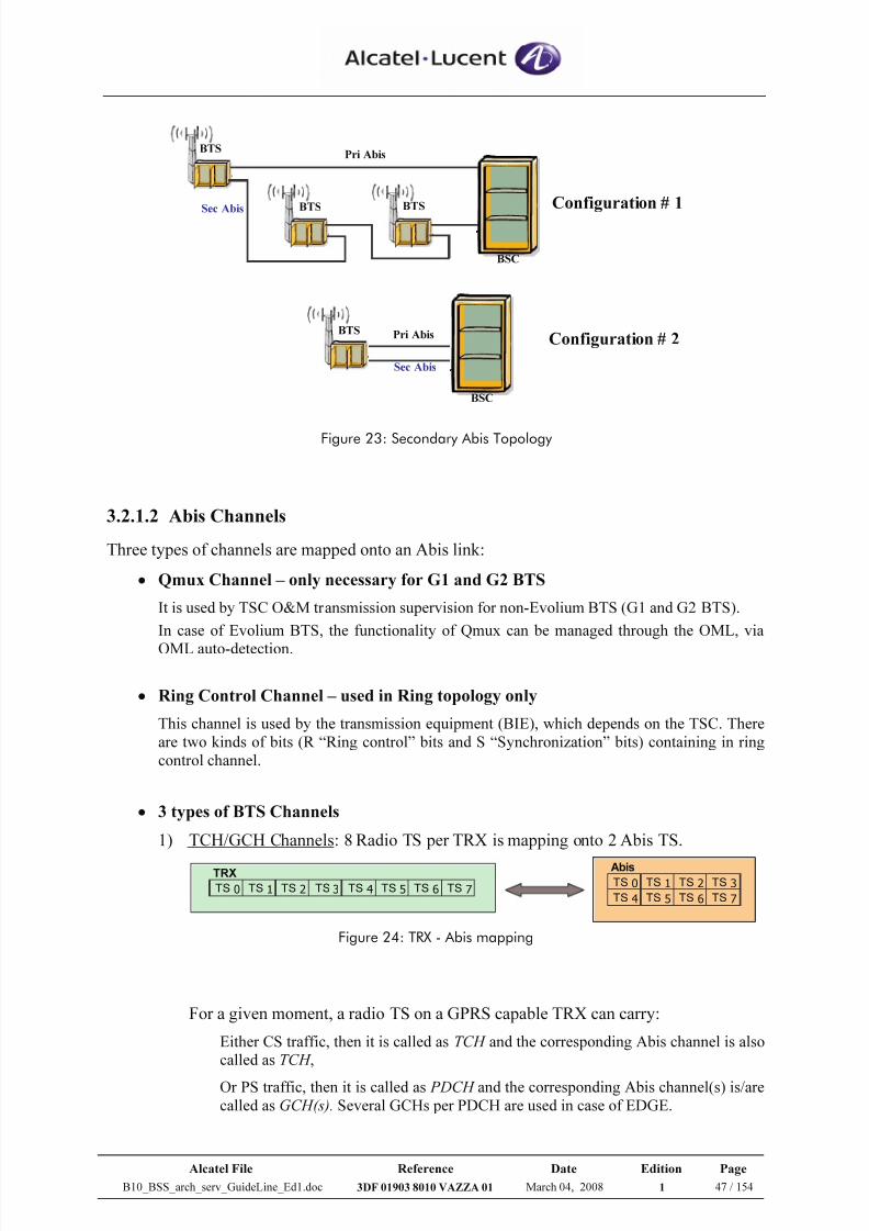
7/21/2019 BSS Architecture Service Guideline B10
http://slidepdf.com/reader/full/bss-architecture-service-guideline-b10 47/154
Alcatel File Reference Date Edition Page
B10_BSS_arch_serv_GuideLine_Ed1.doc 3DF 01903 8010 VAZZA 01 March 04, 2008 1 47 / 154
BTS
BTS
BTS
BSC
Sec Abis
Pri Abis
Configuration # 1
Pri AbisBTS
BSC
Sec Abis
Configuration # 2
Figure 23: Secondary Abis Topology
3.2.1.2 Abis Channels
Three types of channels are mapped onto an Abis link:
• Qmux Channel – only necessary for G1 and G2 BTS
It is used by TSC O&M transmission supervision for non-Evolium BTS (G1 and G2 BTS).
In case of Evolium BTS, the functionality of Qmux can be managed through the OML, via
OML auto-detection.
• Ring Control Channel – used in Ring topology only
This channel is used by the transmission equipment (BIE), which depends on the TSC. There
are two kinds of bits (R “Ring control” bits and S “Synchronization” bits) containing in ring
control channel.
• 3 types of BTS Channels
1) TCH/GCH Channels: 8 Radio TS per TRX is mapping onto 2 Abis TS.
Abis
TS 0 TS 1 TS 2 TS 3
TS 4 TS 5 TS 6 TS 7
TRX
TS 0 TS 1 TS 2 TS 3 TS 4 TS 5 TS 6 TS 7
Figure 24: TRX - Abis mapping
For a given moment, a radio TS on a GPRS capable TRX can carry:
Either CS traffic, then it is called as TCH and the corresponding Abis channel is also
called as TCH ,
Or PS traffic, then it is called as PDCH and the corresponding Abis channel(s) is/are
called as GCH(s). Several GCHs per PDCH are used in case of EDGE.
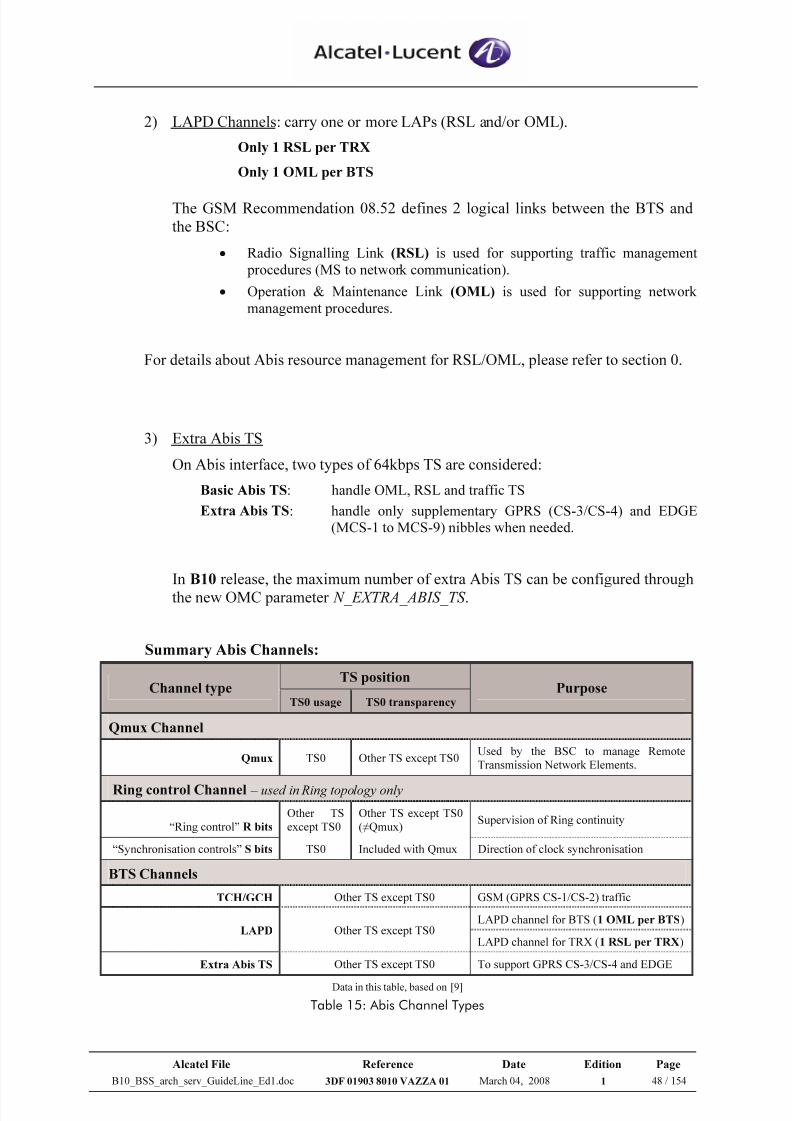
7/21/2019 BSS Architecture Service Guideline B10
http://slidepdf.com/reader/full/bss-architecture-service-guideline-b10 48/154
Alcatel File Reference Date Edition Page
B10_BSS_arch_serv_GuideLine_Ed1.doc 3DF 01903 8010 VAZZA 01 March 04, 2008 1 48 / 154
2) LAPD Channels: carry one or more LAPs (RSL and/or OML).
Only 1 RSL per TRX
Only 1 OML per BTS
The GSM Recommendation 08.52 defines 2 logical links between the BTS and
the BSC:
• Radio Signalling Link (RSL) is used for supporting traffic management
procedures (MS to network communication).
• Operation & Maintenance Link (OML) is used for supporting network
management procedures.
For details about Abis resource management for RSL/OML, please refer to section 0.
3) Extra Abis TS
On Abis interface, two types of 64kbps TS are considered:
Basic Abis TS: handle OML, RSL and traffic TS
Extra Abis TS: handle only supplementary GPRS (CS-3/CS-4) and EDGE
(MCS-1 to MCS-9) nibbles when needed.
In B10 release, the maximum number of extra Abis TS can be configured through
the new OMC parameter N_EXTRA_ABIS_TS .
Summary Abis Channels:
TS positionChannel type
TS0 usage TS0 transparencyPurpose
Qmux Channel
Qmux TS0 Other TS except TS0Used by the BSC to manage Remote
Transmission Network Elements.
Ring control Channel – used in Ring topology only
“Ring control” R bits
Other TS
except TS0
Other TS except TS0
(≠Qmux)Supervision of Ring continuity
“Synchronisation controls” S bits TS0 Included with Qmux Direction of clock synchronisation
BTS Channels
TCH/GCH Other TS except TS0 GSM (GPRS CS-1/CS-2) traffic
LAPD channel for BTS (1 OML per BTS)LAPD Other TS except TS0
LAPD channel for TRX (1 RSL per TRX)
Extra Abis TS Other TS except TS0 To support GPRS CS-3/CS-4 and EDGE
Data in this table, based on [9]
Table 15: Abis Channel Types
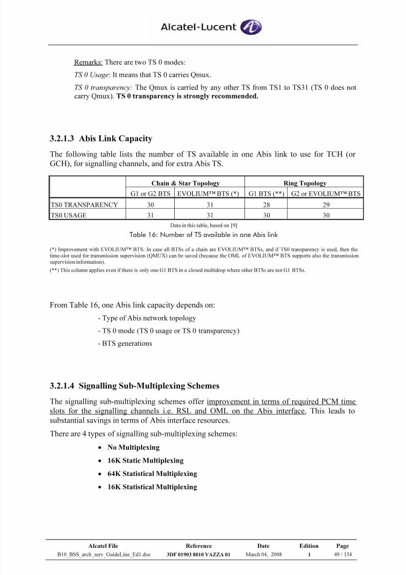
7/21/2019 BSS Architecture Service Guideline B10
http://slidepdf.com/reader/full/bss-architecture-service-guideline-b10 49/154
Alcatel File Reference Date Edition Page
B10_BSS_arch_serv_GuideLine_Ed1.doc 3DF 01903 8010 VAZZA 01 March 04, 2008 1 49 / 154
Remarks: There are two TS 0 modes:
TS 0 Usage: It means that TS 0 carries Qmux.
TS 0 transparency: The Qmux is carried by any other TS from TS1 to TS31 (TS 0 does not
carry Qmux). TS 0 transparency is strongly recommended.
3.2.1.3 Abis Link Capacity
The following table lists the number of TS available in one Abis link to use for TCH (or
GCH), for signalling channels, and for extra Abis TS.
Chain & Star Topology Ring Topology
G1 or G2 BTS EVOLIUM™ BTS (*) G1 BTS (**) G2 or EVOLIUM™ BTS
TS0 TRANSPARENCY 30 31 28 29
TS0 USAGE 31 31 30 30
Data in this table, based on [9]
Table 16: Number of TS available in one Abis link
(*) Improvement with EVOLIUM™ BTS: In case all BTSs of a chain are EVOLIUM™ BTSs, and if TS0 transparency is used, then the
time-slot used for transmission supervision (QMUX) can be saved (because the OML of EVOLIUM™ BTS supports also the transmission
supervision information).
(**) This column applies even if there is only one G1 BTS in a closed multidrop where other BTSs are not G1 BTSs.
From Table 16, one Abis link capacity depends on:
- Type of Abis network topology
- TS 0 mode (TS 0 usage or TS 0 transparency)
- BTS generations
3.2.1.4 Signalling Sub-Multiplexing Schemes
The signalling sub-multiplexing schemes offer improvement in terms of required PCM timeslots for the signalling channels i.e. RSL and OML on the Abis interface. This leads to
substantial savings in terms of Abis interface resources.
There are 4 types of signalling sub-multiplexing schemes:
• No Multiplexing
• 16K Static Multiplexing
• 64K Statistical Multiplexing
• 16K Statistical Multiplexing
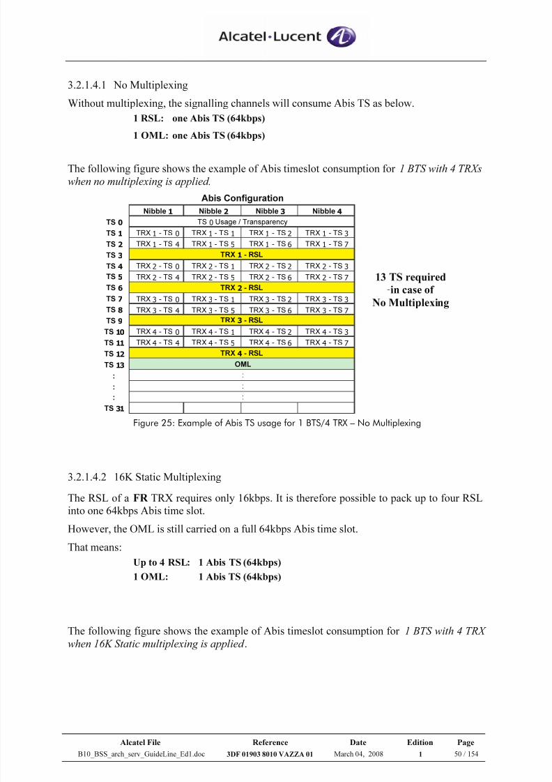
7/21/2019 BSS Architecture Service Guideline B10
http://slidepdf.com/reader/full/bss-architecture-service-guideline-b10 50/154
Alcatel File Reference Date Edition Page
B10_BSS_arch_serv_GuideLine_Ed1.doc 3DF 01903 8010 VAZZA 01 March 04, 2008 1 50 / 154
3.2.1.4.1 No Multiplexing
Without multiplexing, the signalling channels will consume Abis TS as below.
1 RSL: one Abis TS (64kbps)
1 OML: one Abis TS (64kbps)
The following figure shows the example of Abis timeslot consumption for 1 BTS with 4 TRXs
when no multiplexing is applied.
Nibble 1 Nibble 2 Nibble 3 Nibble 4
TS 0
TS 1 TRX 1 - TS 0 TRX 1 - TS 1 TRX 1 - TS 2 TRX 1 - TS 3
TS 2 TRX 1 - TS 4 TRX 1 - TS 5 TRX 1 - TS 6 TRX 1 - TS 7
TS 3
TS 4 TRX 2 - TS 0 TRX 2 - TS 1 TRX 2 - TS 2 TRX 2 - TS 3
TS 5 TRX 2 - TS 4 TRX 2 - TS 5 TRX 2 - TS 6 TRX 2 - TS 7
TS 6
TS 7 TRX 3 - TS 0 TRX 3 - TS 1 TRX 3 - TS 2 TRX 3 - TS 3
TS 8 TRX 3 - TS 4 TRX 3 - TS 5 TRX 3 - TS 6 TRX 3 - TS 7
TS 9
TS 10 TRX 4 - TS 0 TRX 4 - TS 1 TRX 4 - TS 2 TRX 4 - TS 3
TS 11 TRX 4 - TS 4 TRX 4 - TS 5 TRX 4 - TS 6 TRX 4 - TS 7
TS 12
TS 13
:
:
:
TS31
:
:
Abis Configuration
OML
TRX 2 - RSL
TRX 3 - RSL
TRX 4 - RSL
TS 0 Usage / Transparency
TRX 1 - RSL
:
13 TS required in case of
No Multiplexing
Figure 25: Example of Abis TS usage for 1 BTS/4 TRX – No Multiplexing
3.2.1.4.2 16K Static Multiplexing
The RSL of a FR TRX requires only 16kbps. It is therefore possible to pack up to four RSL
into one 64kbps Abis time slot.
However, the OML is still carried on a full 64kbps Abis time slot.
That means:Up to 4 RSL: 1 Abis TS (64kbps)
1 OML: 1 Abis TS (64kbps)
The following figure shows the example of Abis timeslot consumption for 1 BTS with 4 TRX
when 16K Static multiplexing is applied .
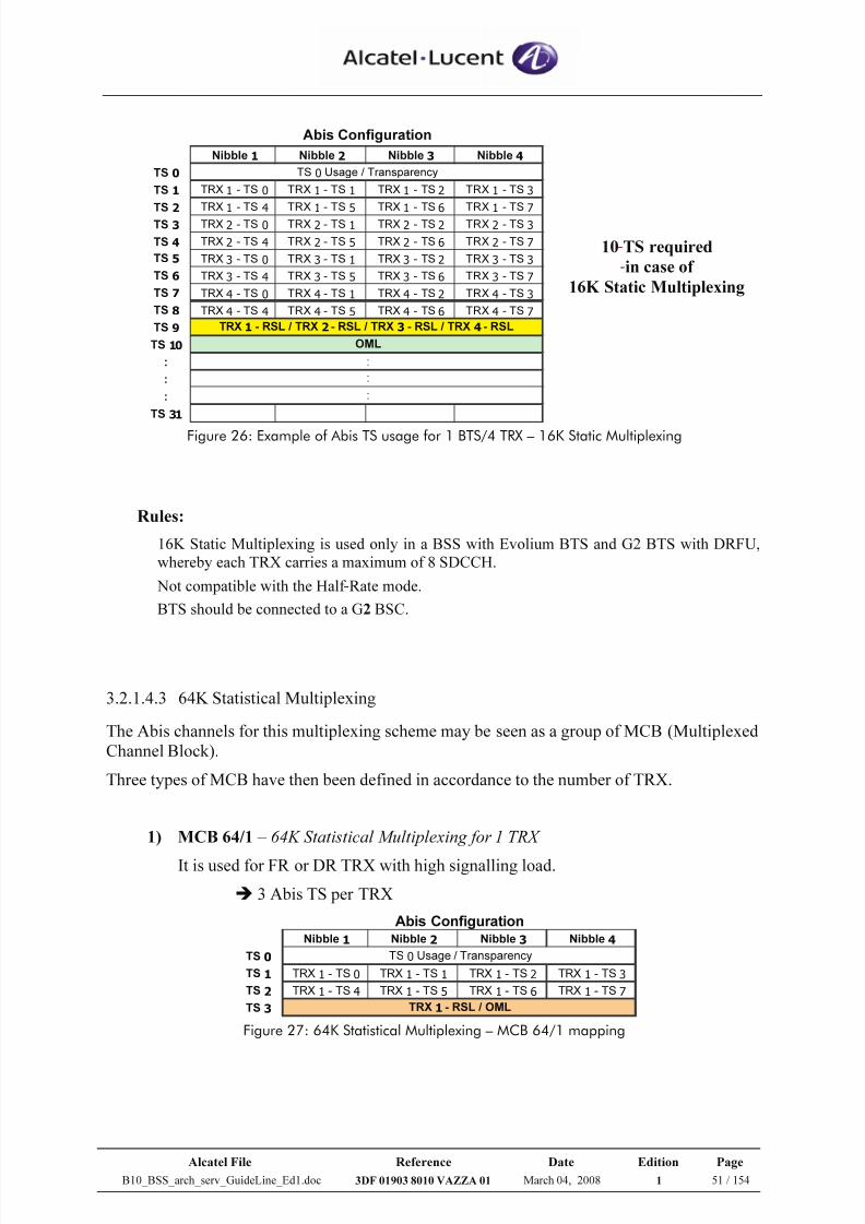
7/21/2019 BSS Architecture Service Guideline B10
http://slidepdf.com/reader/full/bss-architecture-service-guideline-b10 51/154
Alcatel File Reference Date Edition Page
B10_BSS_arch_serv_GuideLine_Ed1.doc 3DF 01903 8010 VAZZA 01 March 04, 2008 1 51 / 154
Nibble 1 Nibble 2 Nibble 3 Nibble 4
TS 0
TS 1 TRX 1 - TS 0 TRX 1 - TS 1 TRX 1 - TS 2 TRX 1 - TS 3
TS 2 TRX 1 - TS 4 TRX 1 - TS 5 TRX 1 - TS 6 TRX 1 - TS 7
TS 3 TRX 2 - TS 0 TRX 2 - TS 1 TRX 2 - TS 2 TRX 2 - TS 3
TS 4 TRX 2 - TS 4 TRX 2 - TS 5 TRX 2 - TS 6 TRX 2 - TS 7
TS 5 TRX 3 - TS 0 TRX 3 - TS 1 TRX 3 - TS 2 TRX 3 - TS 3
TS 6 TRX 3 - TS 4 TRX 3 - TS 5 TRX 3 - TS 6 TRX 3 - TS 7
TS 7 TRX 4 - TS 0 TRX 4 - TS 1 TRX 4 - TS 2 TRX 4 - TS 3
TS 8 TRX 4 - TS 4 TRX 4 - TS 5 TRX 4 - TS 6 TRX 4 - TS 7
TS 9
TS 10
:
:
:
TS 31
:
TRX 1 - RSL / TRX 2 - RSL / TRX 3 - RSL / TRX 4 - RSL
OML
:
:
TS 0 Usage / Transparency
Abis Configuration
10 TS required
in case of
16K Static Multiplexing
Figure 26: Example of Abis TS usage for 1 BTS/4 TRX – 16K Static Multiplexing
Rules:
16K Static Multiplexing is used only in a BSS with Evolium BTS and G2 BTS with DRFU,
whereby each TRX carries a maximum of 8 SDCCH.
Not compatible with the Half -Rate mode.
BTS should be connected to a G2 BSC.
3.2.1.4.3 64K Statistical Multiplexing
The Abis channels for this multiplexing scheme may be seen as a group of MCB (Multiplexed
Channel Block).
Three types of MCB have then been defined in accordance to the number of TRX.
1) MCB 64/1 – 64K Statistical Multiplexing for 1 TRX
It is used for FR or DR TRX with high signalling load.
3 Abis TS per TRX
Nibble 1 Nibble 2 Nibble 3 Nibble 4
TS 0
TS 1 TRX 1 - TS 0 TRX 1 - TS 1 TRX 1 - TS 2 TRX 1 - TS 3
TS 2 TRX 1 - TS 4 TRX 1 - TS 5 TRX 1 - TS 6 TRX 1 - TS 7
TS 3
Abis Configuration
TS 0 Usage / Transparency
TRX 1 - RSL / OML Figure 27: 64K Statistical Multiplexing – MCB 64/1 mapping
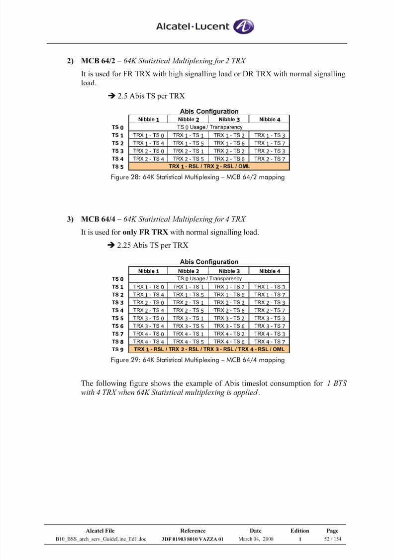
7/21/2019 BSS Architecture Service Guideline B10
http://slidepdf.com/reader/full/bss-architecture-service-guideline-b10 52/154
Alcatel File Reference Date Edition Page
B10_BSS_arch_serv_GuideLine_Ed1.doc 3DF 01903 8010 VAZZA 01 March 04, 2008 1 52 / 154
2) MCB 64/2 – 64K Statistical Multiplexing for 2 TRX
It is used for FR TRX with high signalling load or DR TRX with normal signalling
load.
2.5 Abis TS per TRX Nibble 1 Nibble 2 Nibble 3 Nibble 4
TS 0
TS 1 TRX 1 - TS 0 TRX 1 - TS 1 TRX 1 - TS 2 TRX 1 - TS 3
TS 2 TRX 1 - TS 4 TRX 1 - TS 5 TRX 1 - TS 6 TRX 1 - TS 7
TS 3 TRX 2 - TS 0 TRX 2 - TS 1 TRX 2 - TS 2 TRX 2 - TS 3
TS 4 TRX 2 - TS 4 TRX 2 - TS 5 TRX 2 - TS 6 TRX 2 - TS 7
TS 5
Abis Configuration
TS 0 Usage / Transparency
TRX 1 - RSL / TRX 2 - RSL / OML Figure 28: 64K Statistical Multiplexing – MCB 64/2 mapping
3) MCB 64/4 – 64K Statistical Multiplexing for 4 TRX
It is used for only FR TRX with normal signalling load.
2.25 Abis TS per TRX
Nibble 1 Nibble 2 Nibble 3 Nibble 4
TS 0
TS 1 TRX 1 - TS 0 TRX 1 - TS 1 TRX 1 - TS 2 TRX 1 - TS 3
TS 2 TRX 1 - TS 4 TRX 1 - TS 5 TRX 1 - TS 6 TRX 1 - TS 7
TS 3 TRX 2 - TS 0 TRX 2 - TS 1 TRX 2 - TS 2 TRX 2 - TS 3
TS 4 TRX 2 - TS 4 TRX 2 - TS 5 TRX 2 - TS 6 TRX 2 - TS 7
TS 5 TRX 3 - TS 0 TRX 3 - TS 1 TRX 3 - TS 2 TRX 3 - TS 3
TS 6 TRX 3 - TS 4 TRX 3 - TS 5 TRX 3 - TS 6 TRX 3 - TS 7
TS 7 TRX 4 - TS 0 TRX 4 - TS 1 TRX 4 - TS 2 TRX 4 - TS 3
TS 8 TRX 4 - TS 4 TRX 4 - TS 5 TRX 4 - TS 6 TRX 4 - TS 7
TS 9
Abis Configuration
TS 0 Usage / Transparency
TRX 1 - RSL / TRX 2 - RSL / TRX 3 - RSL / TRX 4 - RSL / OML Figure 29: 64K Statistical Multiplexing – MCB 64/4 mapping
The following figure shows the example of Abis timeslot consumption for 1 BTS
with 4 TRX when 64K Statistical multiplexing is applied .
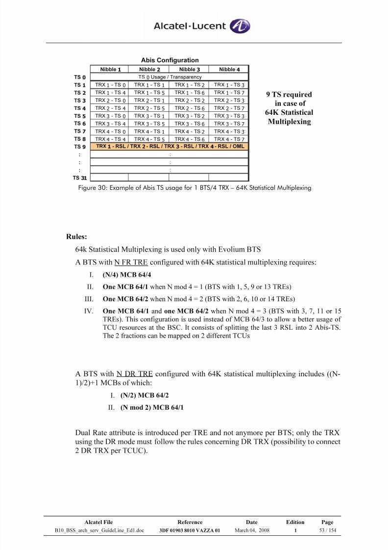
7/21/2019 BSS Architecture Service Guideline B10
http://slidepdf.com/reader/full/bss-architecture-service-guideline-b10 53/154
Alcatel File Reference Date Edition Page
B10_BSS_arch_serv_GuideLine_Ed1.doc 3DF 01903 8010 VAZZA 01 March 04, 2008 1 53 / 154
Nibble 1 Nibble 2 Nibble 3 Nibble 4
TS 0
TS 1 TRX 1 - TS 0 TRX 1 - TS 1 TRX 1 - TS 2 TRX 1 - TS 3
TS 2 TRX 1 - TS 4 TRX 1 - TS 5 TRX 1 - TS 6 TRX 1 - TS 7
TS 3 TRX 2 - TS 0 TRX 2 - TS 1 TRX 2 - TS 2 TRX 2 - TS 3
TS 4 TRX 2 - TS 4 TRX 2 - TS 5 TRX 2 - TS 6 TRX 2 - TS 7
TS 5 TRX 3 - TS 0 TRX 3 - TS 1 TRX 3 - TS 2 TRX 3 - TS 3
TS 6 TRX 3 - TS 4 TRX 3 - TS 5 TRX 3 - TS 6 TRX 3 - TS 7
TS 7 TRX 4 - TS 0 TRX 4 - TS 1 TRX 4 - TS 2 TRX 4 - TS 3
TS 8 TRX 4 - TS 4 TRX 4 - TS 5 TRX 4 - TS 6 TRX 4 - TS 7
TS 9
:
:
:
TS 31
:
Abis Configuration
TS 0 Usage / Transparency
TRX 1 - RSL / TRX 2 - RSL / TRX 3 - RSL / TRX 4 - RSL / OML
:
:
9 TS requiredin case of
64K Statistical
Multiplexing
Figure 30: Example of Abis TS usage for 1 BTS/4 TRX – 64K Statistical Multiplexing
Rules:
64k Statistical Multiplexing is used only with Evolium BTS
A BTS with N FR TRE configured with 64K statistical multiplexing requires:
I. (N/4) MCB 64/4
II. One MCB 64/1 when N mod 4 = 1 (BTS with 1, 5, 9 or 13 TREs)III. One MCB 64/2 when N mod 4 = 2 (BTS with 2, 6, 10 or 14 TREs)
IV. One MCB 64/1 and one MCB 64/2 when N mod 4 = 3 (BTS with 3, 7, 11 or 15
TREs). This configuration is used instead of MCB 64/3 to allow a better usage of
TCU resources at the BSC. It consists of splitting the last 3 RSL into 2 Abis-TS.
The 2 fractions can be mapped on 2 different TCUs
A BTS with N DR TRE configured with 64K statistical multiplexing includes ((N-
1)/2)+1 MCBs of which:I. (N/2) MCB 64/2
II. (N mod 2) MCB 64/1
Dual Rate attribute is introduced per TRE and not anymore per BTS; only the TRX
using the DR mode must follow the rules concerning DR TRX (possibility to connect
2 DR TRX per TCUC).
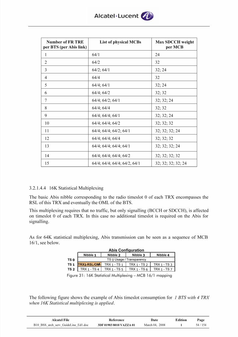
7/21/2019 BSS Architecture Service Guideline B10
http://slidepdf.com/reader/full/bss-architecture-service-guideline-b10 54/154
Alcatel File Reference Date Edition Page
B10_BSS_arch_serv_GuideLine_Ed1.doc 3DF 01903 8010 VAZZA 01 March 04, 2008 1 54 / 154
Number of FR TRE
per BTS (per Abis link)
List of physical MCBs Max SDCCH weight
per MCB
1 64/1 24
2 64/2 32
3 64/2; 64/1 32; 24
4 64/4 32
5 64/4; 64/1 32; 24
6 64/4; 64/2 32; 32
7 64/4; 64/2; 64/1 32; 32; 24
8 64/4; 64/4 32; 32
9 64/4; 64/4; 64/1 32; 32; 24
10 64/4; 64/4; 64/2 32; 32; 32
11 64/4; 64/4; 64/2; 64/1 32; 32; 32; 24
12 64/4; 64/4; 64/4 32; 32; 32
13 64/4; 64/4; 64/4; 64/1 32; 32; 32; 24
14 64/4; 64/4; 64/4; 64/2 32; 32; 32; 32
15 64/4; 64/4; 64/4; 64/2, 64/1 32; 32; 32; 32; 24
3.2.1.4.4 16K Statistical Multiplexing
The basic Abis nibble corresponding to the radio timeslot 0 of each TRX encompasses the
RSL of this TRX and eventually the OML of the BTS.
This multiplexing requires that no traffic, but only signalling (BCCH or SDCCH), is affected
on timeslot 0 of each TRX. In this case no additional timeslot is required on the Abis for
signalling.
As for 64K statistical multiplexing, Abis transmission can be seen as a sequence of MCB16/1, see below.
Nibble 1 Nibble 2 Nibble 3 Nibble 4
TS 0
TS 1 TRX1-RSL/OM TRX 1 - TS 1 TRX 1 - TS 2 TRX 1 - TS 3
TS 2 TRX 1 - TS 4 TRX 1 - TS 5 TRX 1 - TS 6 TRX 1 - TS 7
Abis Configuration
TS 0 Usage / Transparency
Figure 31: 16K Statistical Multiplexing – MCB 16/1 mapping
The following figure shows the example of Abis timeslot consumption for 1 BTS with 4 TRX
when 16K Statistical multiplexing is applied .
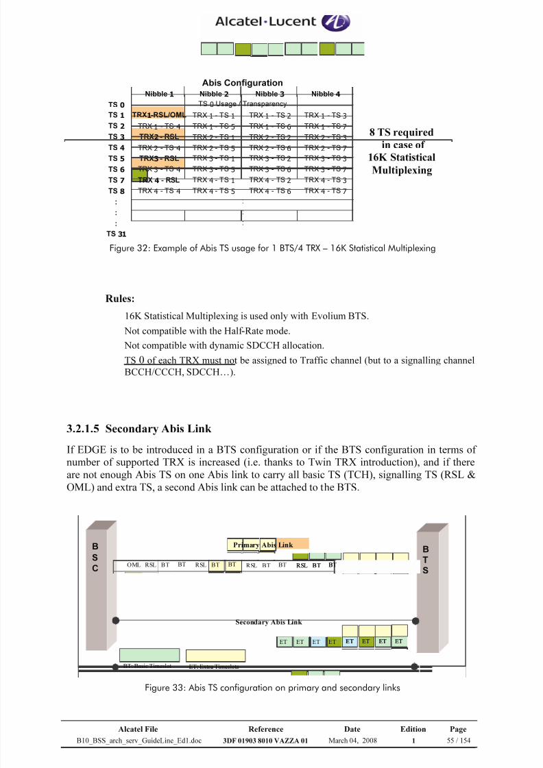
7/21/2019 BSS Architecture Service Guideline B10
http://slidepdf.com/reader/full/bss-architecture-service-guideline-b10 55/154
Alcatel File Reference Date Edition Page
B10_BSS_arch_serv_GuideLine_Ed1.doc 3DF 01903 8010 VAZZA 01 March 04, 2008 1 55 / 154
Nibble 1 Nibble 2 Nibble 3 Nibble 4
TS 0
TS 1 TRX1-RSL/OML TRX 1 - TS 1 TRX 1 - TS 2 TRX 1 - TS 3
TS 2 TRX 1 - TS 4 TRX 1 - TS 5 TRX 1 - TS 6 TRX 1 - TS 7
TS 3 TRX2 - RSL TRX 2 - TS 1 TRX 2 - TS 2 TRX 2 - TS 3
TS 4 TRX 2 - TS 4 TRX 2 - TS 5 TRX 2 - TS 6 TRX 2 - TS 7
TS 5 TRX3 - RSL TRX 3 - TS 1 TRX 3 - TS 2 TRX 3 - TS 3
TS 6 TRX 3 - TS 4 TRX 3 - TS 5 TRX 3 - TS 6 TRX 3 - TS 7
TS 7 TRX 4 - RSL TRX 4 - TS 1 TRX 4 - TS 2 TRX 4 - TS 3
TS 8 TRX 4 - TS 4 TRX 4 - TS 5 TRX 4 - TS 6 TRX 4 - TS 7
:
:
:
TS 31
Abis Configuration
TS 0 Usage / Transparency
:
:
:
8 TS requiredin case of
16K Statistical
Multiplexing
Figure 32: Example of Abis TS usage for 1 BTS/4 TRX – 16K Statistical Multiplexing
Rules:
16K Statistical Multiplexing is used only with Evolium BTS.
Not compatible with the Half -Rate mode.
Not compatible with dynamic SDCCH allocation.
TS 0 of each TRX must not be assigned to Traffic channel (but to a signalling channel
BCCH/CCCH, SDCCH…).
3.2.1.5 Secondary Abis Link
If EDGE is to be introduced in a BTS configuration or if the BTS configuration in terms of
number of supported TRX is increased (i.e. thanks to Twin TRX introduction), and if there
are not enough Abis TS on one Abis link to carry all basic TS (TCH), signalling TS (RSL &
OML) and extra TS, a second Abis link can be attached to the BTS.
B
S
C
B
T
SET ET ET ETOML RSL BT BT RSL BT BT RSL BT BT RSL BT BT
ET ET ET ET ET ET ET ET
Primary Abis Link
Secondary Abis Link
BT: Basic Timeslot ET: Extra Timeslots
B
S
C
B
T
SET ET ET ETET ET ET ETOML RSL BT BTOML RSL BT BT RSL BT BTRSL BT BT RSL BT BTRSL BT BT RSL BT BTRSL BT BT
ET ET ET ETET ET ET ET ET ET ET ETET ET ET ET
Primary Abis Link
Secondary Abis Link
BT: Basic Timeslot ET: Extra Timeslots
Figure 33: Abis TS configuration on primary and secondary links
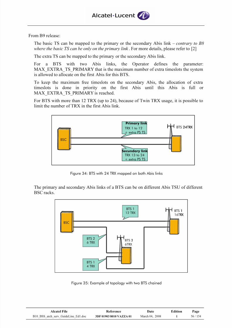
7/21/2019 BSS Architecture Service Guideline B10
http://slidepdf.com/reader/full/bss-architecture-service-guideline-b10 56/154
Alcatel File Reference Date Edition Page
B10_BSS_arch_serv_GuideLine_Ed1.doc 3DF 01903 8010 VAZZA 01 March 04, 2008 1 56 / 154
From B9 release:
The basic TS can be mapped to the primary or the secondary Abis link – contrary to B8
where the basic TS can be only on the primary link . For more details, please refer to [2]
The extra TS can be mapped to the primary or the secondary Abis link.For a BTS with two Abis links, the Operator defines the parameter:
MAX_EXTRA_TS_PRIMARY that is the maximum number of extra timeslots the system
is allowed to allocate on the first Abis for this BTS.
To keep the maximum free timeslots on the secondary Abis, the allocation of extra
timeslots is done in priority on the first Abis until this Abis is full or
MAX_EXTRA_TS_PRIMARY is reached.
For BTS with more than 12 TRX (up to 24), because of Twin TRX usage, it is possible to
limit the number of TRX in the first Abis link.
Figure 34: BTS with 24 TRX mapped on both Abis links
The primary and secondary Abis links of a BTS can be on different Abis TSU of different
BSC racks.
Figure 35: Example of topology with two BTS chained
BSC
BTS 24TRX
Primary link
TRX 1 to 12
+ extra PS TS
Secundary link TRX 13 to 24
+ extra PS TS
BSC
BTS 24TRX
Primary link
TRX 1 to 12
+ extra PS TS
Secundary link TRX 13 to 24
+ extra PS TS
BSC
BTS 2
6TRX
BTS 1
16TRX
BTS 1
12 TRX
BTS 2
6 TRX
BTS 1
4 TRX
BSC
BTS 2
6TRX
BTS 1
16TRX
BTS 1
12 TRX
BTS 2
6 TRX
BTS 1
4 TRX
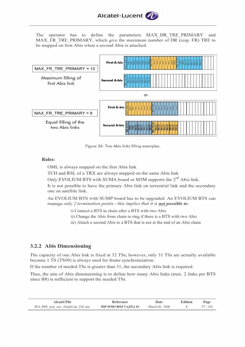
7/21/2019 BSS Architecture Service Guideline B10
http://slidepdf.com/reader/full/bss-architecture-service-guideline-b10 57/154
7/21/2019 BSS Architecture Service Guideline B10
http://slidepdf.com/reader/full/bss-architecture-service-guideline-b10 58/154
Alcatel File Reference Date Edition Page
B10_BSS_arch_serv_GuideLine_Ed1.doc 3DF 01903 8010 VAZZA 01 March 04, 2008 1 58 / 154
The number of needed Abis TS is based on:
• Type of Abis Topology
Chain (Star) or Ring
• TS0 mode
TS 0 usage or TS 0 transparency
• Qmux usage
Used or Not used
• Type of signalling sub-multiplexing schemes
No mux, Static mux(16K), Statistical mux(16K or 64K)
• Number of TRX 2 Abis TSs are needed to support 1 TRX
• Extra Abis TS
New type of Abis TS, introduced since B8, to support
GPRS CS3-CS4 and EDGE services because 1 basic
Abis TS is not enough to transport the high data
throughput of those services.
1 Extra Abis TS contains 4 GCHs (nibbles). Various number of required GCH is based on
modulation & coding scheme (MCS or CS), please
refer to 3.4.4.2.3.
Less GCH consumption in B9 – thanks to M-EGCH
and dynamic Abis allocation
Max number of extra Abis TS is limited by parameter
N_EXTRA_ABIS_TS
It is simple to define the number of needed Abis TSs for conditions of topology, TS0 mode,
Qmux usage, signalling sub-mux and number of TRX because each of them requires the
certain number of TSs.
The most complicated part of Abis dimensioning from B9 release is how to define the number
of extra Abis TSs per BTS, as this kind of TS is allocated dynamically on Abis link when
needed by traffic demand and it can be shared among the BTS sector.
The following presents the Abis dimensioning processes to define the needed extra Abis TSs
based on the counter analysis.
“Static”
number of
needed
Abis TSs
“Dynamic”number of
needed Abis
TSs
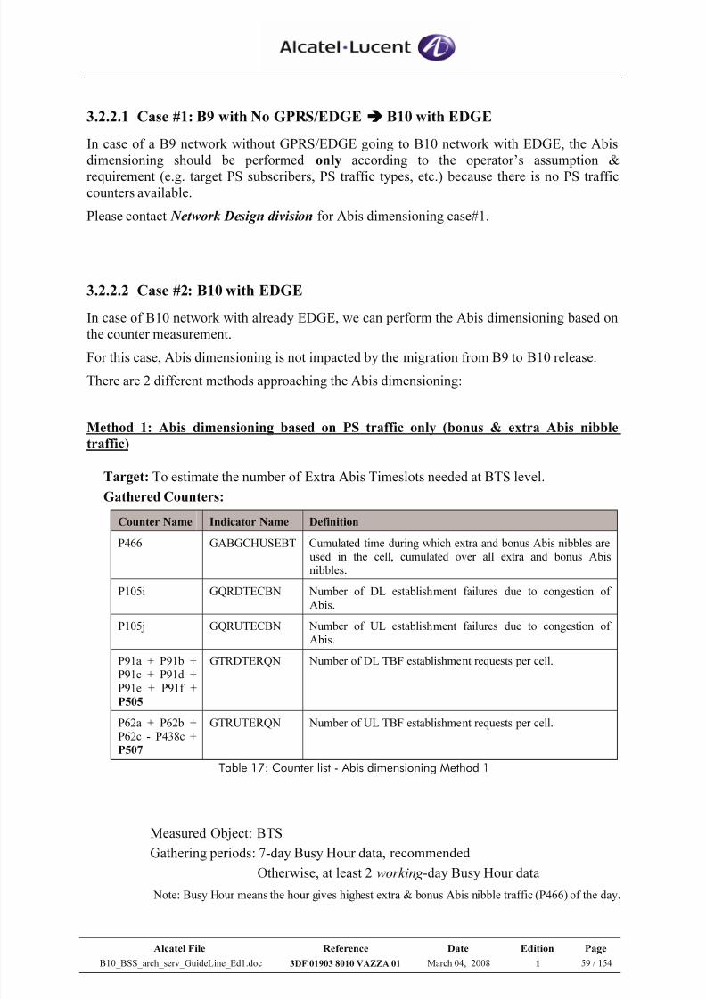
7/21/2019 BSS Architecture Service Guideline B10
http://slidepdf.com/reader/full/bss-architecture-service-guideline-b10 59/154
Alcatel File Reference Date Edition Page
B10_BSS_arch_serv_GuideLine_Ed1.doc 3DF 01903 8010 VAZZA 01 March 04, 2008 1 59 / 154
3.2.2.1 Case #1: B9 with No GPRS/EDGE B10 with EDGE
In case of a B9 network without GPRS/EDGE going to B10 network with EDGE, the Abis
dimensioning should be performed only according to the operator’s assumption &
requirement (e.g. target PS subscribers, PS traffic types, etc.) because there is no PS trafficcounters available.
Please contact Network Design division for Abis dimensioning case#1.
3.2.2.2 Case #2: B10 with EDGE
In case of B10 network with already EDGE, we can perform the Abis dimensioning based on
the counter measurement.
For this case, Abis dimensioning is not impacted by the migration from B9 to B10 release.
There are 2 different methods approaching the Abis dimensioning:
Method 1: Abis dimensioning based on PS traffic only (bonus & extra Abis nibble
traffic)
Target: To estimate the number of Extra Abis Timeslots needed at BTS level.
Gathered Counters:
Counter Name Indicator Name Definition
P466 GABGCHUSEBT Cumulated time during which extra and bonus Abis nibbles areused in the cell, cumulated over all extra and bonus Abisnibbles.
P105i GQRDTECBN Number of DL establishment failures due to congestion of
Abis.
P105j GQRUTECBN Number of UL establishment failures due to congestion of Abis.
P91a + P91b +P91c + P91d +P91e + P91f +
P505
GTRDTERQN Number of DL TBF establishment requests per cell.
P62a + P62b +P62c - P438c +
P507
GTRUTERQN Number of UL TBF establishment requests per cell.
Table 17: Counter list - Abis dimensioning Method 1
Measured Object: BTS
Gathering periods: 7-day Busy Hour data, recommended
Otherwise, at least 2 working -day Busy Hour data Note: Busy Hour means the hour gives highest extra & bonus Abis nibble traffic (P466) of the day.
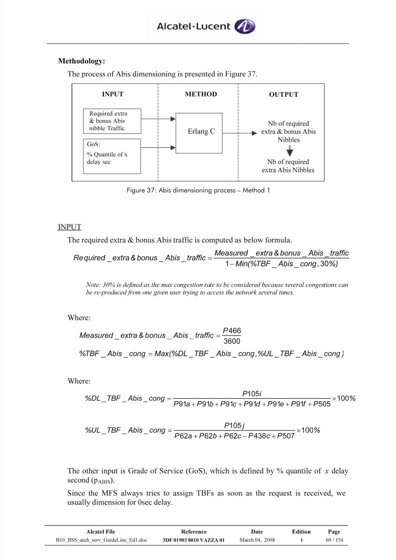
7/21/2019 BSS Architecture Service Guideline B10
http://slidepdf.com/reader/full/bss-architecture-service-guideline-b10 60/154
Alcatel File Reference Date Edition Page
B10_BSS_arch_serv_GuideLine_Ed1.doc 3DF 01903 8010 VAZZA 01 March 04, 2008 1 60 / 154
Methodology:
The process of Abis dimensioning is presented in Figure 37.
Erlang C
Required extra
& bonus Abis
nibble Traffic
GoS:
% Quantile of x
delay sec
Nb of requiredextra & bonus Abis
Nibbles
INPUT OUTPUTMETHOD
Nb of required
extra Abis Nibbles
Figure 37: Abis dimensioning process – Method 1
INPUT
The required extra & bonus Abis traffic is computed as below formula.
%),cong _ Abis _TBF (%Min
traffic _ Abis _bonus&extra _Measured traffic _ Abis _bonus&extra _quired Re
301−=
Note: 30% is defined as the max congestion rate to be considered because several congestions can
be re-produced from one given user trying to access the network several times.
Where:
3600
466P traffic _ Abis _bonus&extra _Measured =
)cong _ Abis _TBF _UL,%cong _ Abis _TBF _DL(%Max cong _ Abis _TBF % =
Where:
%P f P eP d P c P bP aP
i P cong _ Abis _TBF _DL% 100505919191919191
105×
++++++
=
%P c P c P bP aP
j P cong _ Abis _TBF _UL% 100
507438626262
105×
+−++
=
The other input is Grade of Service (GoS), which is defined by % quantile of x delay
second (pABIS).
Since the MFS always tries to assign TBFs as soon as the request is received, weusually dimension for 0sec delay.
7/21/2019 BSS Architecture Service Guideline B10
http://slidepdf.com/reader/full/bss-architecture-service-guideline-b10 61/154
Alcatel File Reference Date Edition Page
B10_BSS_arch_serv_GuideLine_Ed1.doc 3DF 01903 8010 VAZZA 01 March 04, 2008 1 61 / 154
Normally GoS should be given or agreed by the Operator.
On Abis interface, the recommended value is 95% quantile of 0 delay sec.
METHOD
Concerning only PS traffic, the statistical law Erlang C is used during the dimensioning
process to determine the necessary resources versus the traffic and the target GoS.
As extra & bonus Abis nibbles are associated to PS traffic only, Erlang C can be
applied to calculate the required number of extra & bonus Abis nibbles according to
required PS traffic and % quantile of delay time.
OUTPUT
Number of required extra & bonus Abis nibbles
= Erlang C (Required_extra&bonus_Abis_traffic, pABIS)
However the number of bonus Abis nibbles is fixed according to the total number of
BCCH & SDCCH TS in the BTS; i.e. one BCCH (SDCCH) TS gives one bonus Abis
nibble.
Then,
Number of required extra Abis nibbles
= Number of required extra & bonus Abis nibbles – Nbr of bonus Abis nibbles
And
Number of required extra Abis TS
= Number of required extra Abis nibbles / 4
Remark: 1 Abis TS contains 4 Abis nibble
Assessment:
In order to assess the Abis dimensioning, it is suggested to monitor if there is any
impact caused by Abis congestion afterward.
The major degradations due to Abis congestion are:
TBF establishment failures due to Abis congestion:
%1,0 _ _ _ % >cong AbisTBF
Radio throughput reduction: a method for throughput degradation is under
study
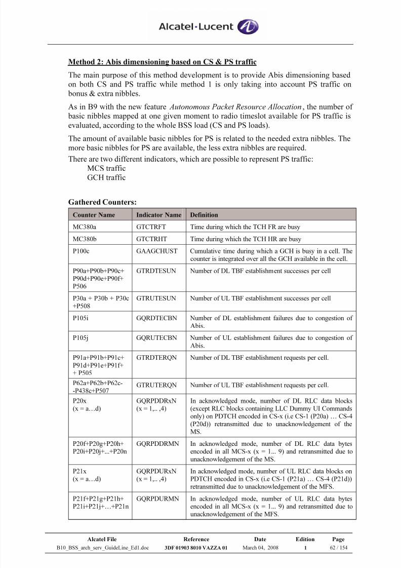
7/21/2019 BSS Architecture Service Guideline B10
http://slidepdf.com/reader/full/bss-architecture-service-guideline-b10 62/154
Alcatel File Reference Date Edition Page
B10_BSS_arch_serv_GuideLine_Ed1.doc 3DF 01903 8010 VAZZA 01 March 04, 2008 1 62 / 154
Method 2: Abis dimensioning based on CS & PS traffic
The main purpose of this method development is to provide Abis dimensioning based
on both CS and PS traffic while method 1 is only taking into account PS traffic on
bonus & extra nibbles.
As in B9 with the new feature Autonomous Packet Resource Allocation, the number of
basic nibbles mapped at one given moment to radio timeslot available for PS traffic is
evaluated, according to the whole BSS load (CS and PS loads).
The amount of available basic nibbles for PS is related to the needed extra nibbles. The
more basic nibbles for PS are available, the less extra nibbles are required.
There are two different indicators, which are possible to represent PS traffic:
MCS traffic
GCH traffic
Gathered Counters:
Counter Name Indicator Name Definition
MC380a GTCTRFT Time during which the TCH FR are busy
MC380b GTCTRHT Time during which the TCH HR are busy
P100c GAAGCHUST Cumulative time during which a GCH is busy in a cell. Thecounter is integrated over all the GCH available in the cell.
P90a+P90b+P90c+P90d+P90e+P90f+P506
GTRDTESUN Number of DL TBF establishment successes per cell
P30a + P30b + P30c+P508
GTRUTESUN Number of UL TBF establishment successes per cell
P105i GQRDTECBN Number of DL establishment failures due to congestion of Abis.
P105j GQRUTECBN Number of UL establishment failures due to congestion of
Abis.
P91a+P91b+P91c+
P91d+P91e+P91f++ P505
GTRDTERQN Number of DL TBF establishment requests per cell.
P62a+P62b+P62c--P438c+P507
GTRUTERQN Number of UL TBF establishment requests per cell.
P20x(x = a…d)
GQRPDDRxN(x = 1,.. ,4)
In acknowledged mode, number of DL RLC data blocks(except RLC blocks containing LLC Dummy UI Commandsonly) on PDTCH encoded in CS-x (i.e CS-1 (P20a) … CS-4
(P20d)) retransmitted due to unacknowledgement of theMS.
P20f+P20g+P20h+P20i+P20j+...+P20n
GQRPDDRMN In acknowledged mode, number of DL RLC data bytesencoded in all MCS-x (x = 1... 9) and retransmitted due to
unacknowledgement of the MS.
P21x(x = a…d)
GQRPDURxN(x = 1,.. ,4)
In acknowledged mode, number of UL RLC data blocks onPDTCH encoded in CS-x (i.e CS-1 (P21a) … CS-4 (P21d))retransmitted due to unacknowledgement of the MFS.
P21f+P21g+P21h+P21i+P21j+…+P21n
GQRPDURMN In acknowledged mode, number of UL RLC data bytesencoded in all MCS-x (x = 1... 9) and retransmitted due tounacknowledgement of the MFS.
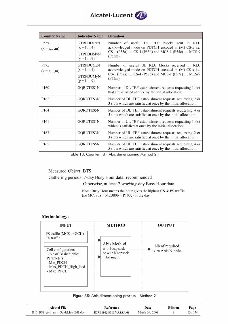
7/21/2019 BSS Architecture Service Guideline B10
http://slidepdf.com/reader/full/bss-architecture-service-guideline-b10 63/154
Alcatel File Reference Date Edition Page
B10_BSS_arch_serv_GuideLine_Ed1.doc 3DF 01903 8010 VAZZA 01 March 04, 2008 1 63 / 154
Counter Name Indicator Name Definition
P55x
(x = a,.. ,m)
GTRPDDCxN(x = 1,.. ,4)
GTRPDDMyN(y = 1,.. ,9)
Number of useful DL RLC blocks sent in RLCacknowledged mode on PDTCH encoded in (M) CS-x i.e.CS-1 (P55a) … CS-4 (P55d) and MCS-1 (P55e) … MCS-9
(P55m).
P57x
(x = a,.. ,m)
GTRPDUCxN(x = 1,.. ,4)
GTRPDUMyN(y = 1,.. ,9)
Number of useful UL RLC blocks received in RLCacknowledged mode on PDTCH encoded in (M) CS-x i.e.
CS-1 (P57a) … CS-4 (P57d) and MCS-1 (P57e) … MCS-9(P57m).
P160 GQRDTES1N Number of DL TBF establishment requests requesting 1 slot
that are satisfied at once by the initial allocation.
P162 GQRDTES3N Number of DL TBF establishment requests requesting 2 or3 slots which are satisfied at once by the initial allocation.
P164 GQRDTES5N Number of DL TBF establishment requests requesting 4 or
5 slots which are satisfied at once by the initial allocation.
P161 GQRUTES1N Number of UL TBF establishment requests requesting 1 slot
which is satisfied at once by the initial allocation.
P163 GQRUTES3N Number of UL TBF establishment requests requesting 2 or3 slots which are satisfied at once by the initial allocation.
P165 GQRUTES5N Number of UL TBF establishment requests requesting 4 or5 slots which are satisfied at once by the initial allocation.
Table 18: Counter list - Abis dimensioning Method 2.1
Measured Object: BTS
Gathering periods: 7-day Busy Hour data, recommended
Otherwise, at least 2 working -day Busy Hour data
Note: Busy Hour means the hour gives the highest CS & PS traffic(i.e MC380a + MC380b + P100c) of the day.
Methodology:
Abis Method
with Knapsack
or with Knapsack
+ Erlang C
PS traffic (MCS or GCH)
CS traffic
Cell configuration:
- Nb of Basic nibbles
Parameters:
- Min_PDCH- Max_PDCH_High_load
- Max_PDCH
INPUT OUTPUTMETHOD
Nb of required
extra Abis Nibbles
Figure 38: Abis dimensioning process – Method 2
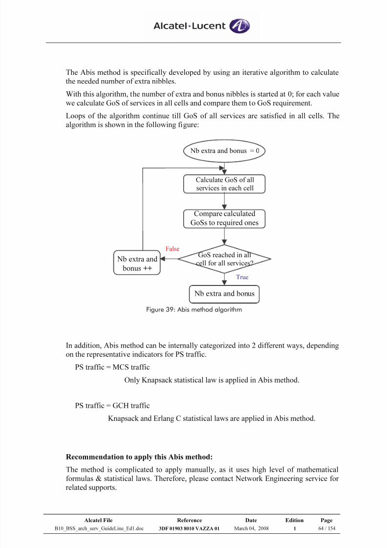
7/21/2019 BSS Architecture Service Guideline B10
http://slidepdf.com/reader/full/bss-architecture-service-guideline-b10 64/154
Alcatel File Reference Date Edition Page
B10_BSS_arch_serv_GuideLine_Ed1.doc 3DF 01903 8010 VAZZA 01 March 04, 2008 1 64 / 154
The Abis method is specifically developed by using an iterative algorithm to calculate
the needed number of extra nibbles.
With this algorithm, the number of extra and bonus nibbles is started at 0; for each valuewe calculate GoS of services in all cells and compare them to GoS requirement.
Loops of the algorithm continue till GoS of all services are satisfied in all cells. The
algorithm is shown in the following figure:
GoS reached in all
cell for all services?
Calculate GoS of all
services in each cell
Compare calculated
GoSs to required ones
Nb extra and bonus = 0
Nb extra and bonus
Nb extra and
bonus ++True
False
Figure 39: Abis method algorithm
In addition, Abis method can be internally categorized into 2 different ways, depending
on the representative indicators for PS traffic.
PS traffic = MCS traffic
Only Knapsack statistical law is applied in Abis method.
PS traffic = GCH traffic
Knapsack and Erlang C statistical laws are applied in Abis method.
Recommendation to apply this Abis method:
The method is complicated to apply manually, as it uses high level of mathematical
formulas & statistical laws. Therefore, please contact Network Engineering service forrelated supports.
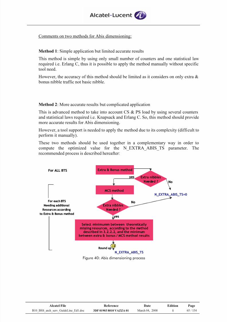
7/21/2019 BSS Architecture Service Guideline B10
http://slidepdf.com/reader/full/bss-architecture-service-guideline-b10 65/154
Alcatel File Reference Date Edition Page
B10_BSS_arch_serv_GuideLine_Ed1.doc 3DF 01903 8010 VAZZA 01 March 04, 2008 1 65 / 154
Comments on two methods for Abis dimensioning:
Method 1: Simple application but limited accurate results
This method is simple by using only small number of counters and one statistical law
required i.e. Erlang C, thus it is possible to apply the method manually without specific
tool need.
However, the accuracy of this method should be limited as it considers on only extra &
bonus nibble traffic not basic nibble.
Method 2: More accurate results but complicated application
This is advanced method to take into account CS & PS load by using several countersand statistical laws required i.e. Knapsack and Erlang C. So, this method should provide
more accurate results for Abis dimensioning.
However, a tool support is needed to apply the method due to its complexity (difficult to
perform it manually).
These two methods should be used together in a complementary way in order to
compute the optimized value for the N_EXTRA_ABIS_TS parameter. The
recommended process is described hereafter:
Extra & Bonus method
MCS method
For ALL BTS
Extra nibbles
Needed ?
Extra nibbles
Needed ?
Select minimumm between theoreticallymissing resources, according to the methoddescribed in 3.2.2.2, and the minimum
between extra & bonus / MCS method results
yes
yes
No
NoFor each BTS
Needing additional
Resources according
to Extra & Bonus method
/4Round up
N_EXTRA_ABIS_TS
N_EXTRA_ABIS_TS=0
Figure 40: Abis dimensioning process
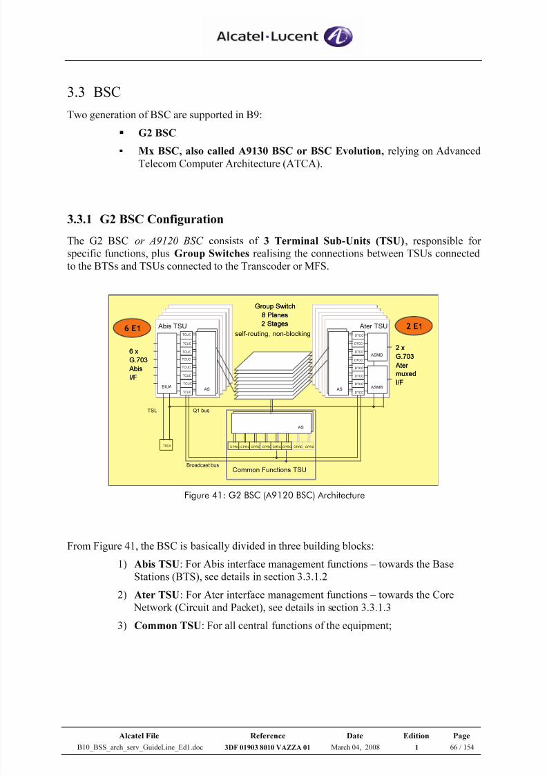
7/21/2019 BSS Architecture Service Guideline B10
http://slidepdf.com/reader/full/bss-architecture-service-guideline-b10 66/154
Alcatel File Reference Date Edition Page
B10_BSS_arch_serv_GuideLine_Ed1.doc 3DF 01903 8010 VAZZA 01 March 04, 2008 1 66 / 154
3.3 BSC
Two generation of BSC are supported in B9:
G2 BSC
Mx BSC, also called A9130 BSC or BSC Evolution, relying on Advanced
Telecom Computer Architecture (ATCA).
3.3.1 G2 BSC Configuration
The G2 BSC or A9120 BSC consists of 3 Terminal Sub-Units (TSU), responsible for
specific functions, plus Group Switches realising the connections between TSUs connected
to the BTSs and TSUs connected to the Transcoder or MFS.
Group Switch
8 Planes
2 Stages
BIUA
TCUC
TCUC
TCUC
TCUC
TCUC
TCUC
TCUC
TCUC
AS
DTCC
DTCC
DTCC
DTCC
DTCC
DTCC
DTCC
AS
DTCC
CPRC CPRC CPRC CPRC CPRC CPRC CPRC CPRC
AS
6 x
G.703
Abis
I/F
2 x
G.703
Ater
muxed
I/F
Abis TSU Ater TSU
Common Functions TSU
TSCA
TSL
ASMB
ASMB
Q1 bus
Broadcast bus
self-routing, non-blocking6 E1 2 E1
Group Switch
8 Planes
2 Stages
Group Switch
8 Planes
2 Stages
BIUA
TCUC
TCUC
TCUC
TCUC
TCUC
TCUC
TCUC
TCUC
AS
DTCC
DTCC
DTCC
DTCC
DTCC
DTCC
DTCC
AS
DTCC
CPRC CPRC CPRC CPRC CPRC CPRC CPRC CPRC
AS
6 x
G.703
Abis
I/F
6 x
G.703
Abis
I/F
2 x
G.703
Ater
muxed
I/F
2 x
G.703
Ater
muxed
I/F
Abis TSU Ater TSU
Common Functions TSU
TSCA
TSL
ASMB
ASMB
Q1 bus
Broadcast bus
self-routing, non-blocking6 E1 2 E1
Figure 41: G2 BSC (A9120 BSC) Architecture
From Figure 41, the BSC is basically divided in three building blocks:
1) Abis TSU: For Abis interface management functions – towards the Base
Stations (BTS), see details in section 3.3.1.2
2) Ater TSU: For Ater interface management functions – towards the Core
Network (Circuit and Packet), see details in section 3.3.1.3
3) Common TSU: For all central functions of the equipment;
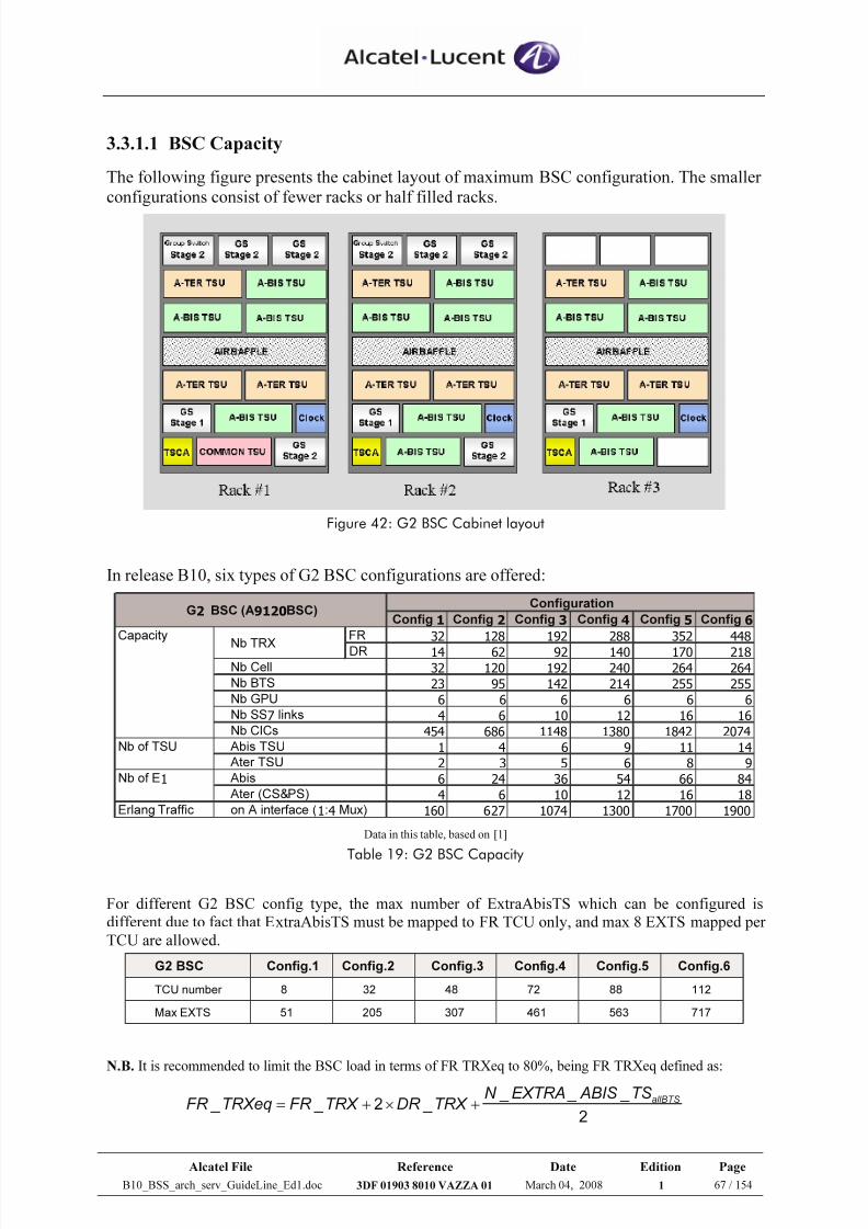
7/21/2019 BSS Architecture Service Guideline B10
http://slidepdf.com/reader/full/bss-architecture-service-guideline-b10 67/154
Alcatel File Reference Date Edition Page
B10_BSS_arch_serv_GuideLine_Ed1.doc 3DF 01903 8010 VAZZA 01 March 04, 2008 1 67 / 154
3.3.1.1 BSC Capacity
The following figure presents the cabinet layout of maximum BSC configuration. The smaller
configurations consist of fewer racks or half filled racks.
Figure 42: G2 BSC Cabinet layout
In release B10, six types of G2 BSC configurations are offered:
Config 1 Config 2 Config 3 Config 4 Config 5 Config 6
Capacity FR 32 128 192 288 352 448
DR 14 62 92 140 170 218
32 120 192 240 264 264
23 95 142 214 255 255
6 6 6 6 6 6
4 6 10 12 16 16
454 686 1148 1380 1842 2074
Nb of TSU 1 4 6 9 11 14
2 3 5 6 8 9
Nb of E1 6 24 36 54 66 84
4 6 10 12 16 18
Erlang Traffic 160 627 1074 1300 1700 1900
G2 BSC (A9120BSC)Configuration
Abis
Ater (CS&PS)
on A interface (1:4 Mux)
Nb TRX
Nb Cell
Nb BTS
Nb GPU
Nb SS7 links
Nb CICs
Abis TSU
Ater TSU
Data in this table, based on [1]
Table 19: G2 BSC Capacity
For different G2 BSC config type, the max number of ExtraAbisTS which can be configured isdifferent due to fact that ExtraAbisTS must be mapped to FR TCU only, and max 8 EXTS mapped perTCU are allowed.
G2 BSC Config.1 Config.2 Config.3 Config.4 Config.5 Config.6
TCU number 8 32 48 72 88 112
Max EXTS 51 205 307 461 563 717
N.B. It is recommended to limit the BSC load in terms of FR TRXeq to 80%, being FR TRXeq defined as:
22
allBTSTS _ ABIS _EXTRA _N
TRX _DR TRX _FR TRXeq _FR +×+=
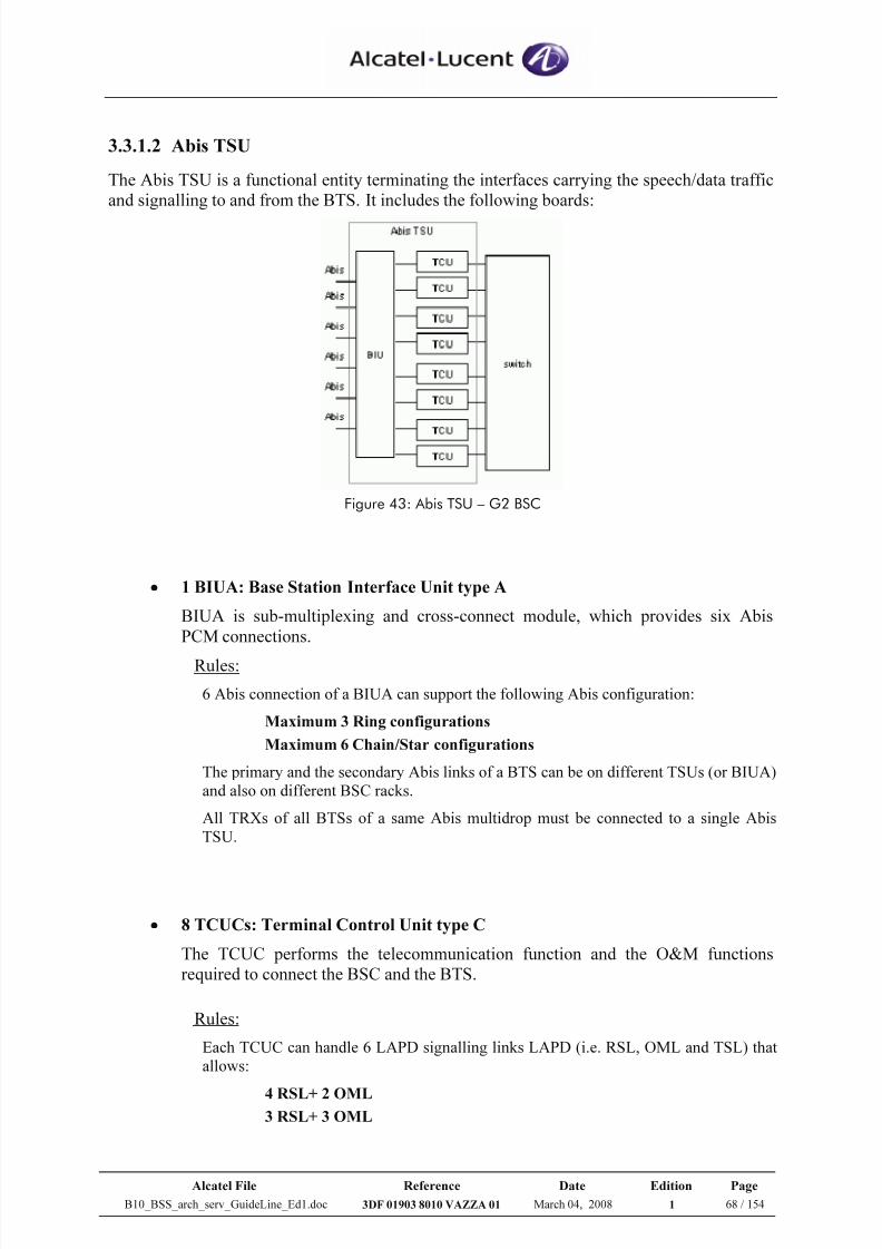
7/21/2019 BSS Architecture Service Guideline B10
http://slidepdf.com/reader/full/bss-architecture-service-guideline-b10 68/154
Alcatel File Reference Date Edition Page
B10_BSS_arch_serv_GuideLine_Ed1.doc 3DF 01903 8010 VAZZA 01 March 04, 2008 1 68 / 154
3.3.1.2 Abis TSU
The Abis TSU is a functional entity terminating the interfaces carrying the speech/data traffic
and signalling to and from the BTS. It includes the following boards:
Figure 43: Abis TSU – G2 BSC
• 1 BIUA: Base Station Interface Unit type A
BIUA is sub-multiplexing and cross-connect module, which provides six Abis
PCM connections.
Rules:
6 Abis connection of a BIUA can support the following Abis configuration:
Maximum 3 Ring configurations
Maximum 6 Chain/Star configurations
The primary and the secondary Abis links of a BTS can be on different TSUs (or BIUA)and also on different BSC racks.
All TRXs of all BTSs of a same Abis multidrop must be connected to a single AbisTSU.
• 8 TCUCs: Terminal Control Unit type C
The TCUC performs the telecommunication function and the O&M functions
required to connect the BSC and the BTS.
Rules:
Each TCUC can handle 6 LAPD signalling links LAPD (i.e. RSL, OML and TSL) thatallows:
4 RSL+ 2 OML3 RSL+ 3 OML
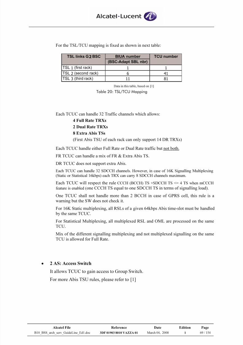
7/21/2019 BSS Architecture Service Guideline B10
http://slidepdf.com/reader/full/bss-architecture-service-guideline-b10 69/154
Alcatel File Reference Date Edition Page
B10_BSS_arch_serv_GuideLine_Ed1.doc 3DF 01903 8010 VAZZA 01 March 04, 2008 1 69 / 154
For the TSL/TCU mapping is fixed as shown in next table:
BIUA number
(BSC-Adapt SBL nbr)
TSL 1 (first rack) 1 1
TSL 2 (second rack) 6 41
TSL 3 (third rack) 11 81
TSL links G2BSC TCU number
Data in this table, based on [1]
Table 20: TSL/TCU Mapping
Each TCUC can handle 32 Traffic channels which allows:
4 Full Rate TRXs2 Dual Rate TRXs
8 Extra Abis TSs
(First Abis TSU of each rack can only support 14 DR TRXs)
Each TCUC handle either Full Rate or Dual Rate traffic but not both.
FR TCUC can handle a mix of FR & Extra Abis TS.
DR TCUC does not support extra Abis.
Each TCUC can handle 32 SDCCH channels. However, in case of 16K Signalling Multiplexing
(Static or Statistical 16kbps) each TRX can carry 8 SDCCH channels maximum.
Each TCUC will respect the rule CCCH (BCCH) TS +SDCCH TS <= 4 TS when mCCCH
feature is enabled (one CCCH TS equal to one SDCCH TS in terms of signalling load).
One TCUC shall not handle more than 2 BCCH in case of GPRS cell, this rule is awarning but the SW does not check it.
For 16K Static multiplexing, all RSLs of a given 64kbps Abis time-slot must be handled by the same TCUC.
For Statistical Multiplexing, all multiplexed RSL and OML are processed on the sameTCU.
Mix of the different signalling multiplexing and not multiplexed signalling on the sameTCU is allowed for Full Rate.
• 2 AS: Access Switch
It allows TCUC to gain access to Group Switch.
For more Abis TSU rules, please refer to [1]
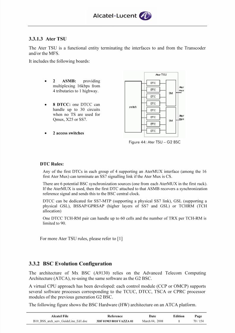
7/21/2019 BSS Architecture Service Guideline B10
http://slidepdf.com/reader/full/bss-architecture-service-guideline-b10 70/154
Alcatel File Reference Date Edition Page
B10_BSS_arch_serv_GuideLine_Ed1.doc 3DF 01903 8010 VAZZA 01 March 04, 2008 1 70 / 154
3.3.1.3 Ater TSU
The Ater TSU is a functional entity terminating the interfaces to and from the Transcoder
and/or the MFS.
It includes the following boards:
• 2 ASMB: providingmultiplexing 16kbps from4 tributaries to 1 highway.
• 8 DTCC: one DTCC canhandle up to 30 circuits
when no TS are used forQmux, X25 or SS7.
• 2 access switches
Figure 44: Ater TSU – G2 BSC
DTC Rules:
Any of the first DTCs in each group of 4 supporting an AterMUX interface (among the 16
first Ater Mux) can terminate an SS7 signalling link if the Ater Mux is CS.
There are 6 potential BSC synchronization sources (one from each AterMUX in the first rack).If the AterMUX is used, then the first DTC attached to that ASMB recovers a synchronizationreference signal and sends this to the BSC central clock.
DTCC can be dedicated for SS7-MTP (supporting a physical SS7 link), GSL (supporting a physical GSL), BSSAP/GPRSAP (higher layers of SS7 and GSL) or TCHRM (TCHallocation)
One DTCC TCH-RM pair can handle up to 60 cells and the number of TRX per TCH-RM islimited to 90.
For more Ater TSU rules, please refer to [1]
3.3.2 BSC Evolution Configuration
The architecture of Mx BSC (A9130) relies on the Advanced Telecom Computing
Architecture (ATCA), re-using the same software as the G2 BSC.
A virtual CPU approach has been developed: each control module (CCP or OMCP) supports
several software processes corresponding to the TCUC, DTCC, TSCA or CPRC processormodules of the previous generation G2 BSC.
The following figure shows the BSC Hardware (HW) architecture on an ATCA platform.
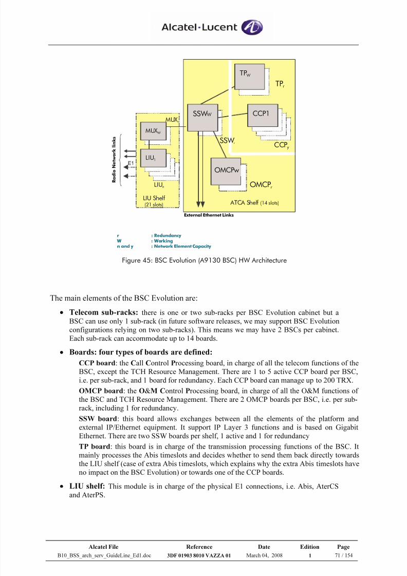
7/21/2019 BSS Architecture Service Guideline B10
http://slidepdf.com/reader/full/bss-architecture-service-guideline-b10 71/154
Alcatel File Reference Date Edition Page
B10_BSS_arch_serv_GuideLine_Ed1.doc 3DF 01903 8010 VAZZA 01 March 04, 2008 1 71 / 154
SSW W
R a d i o N e t w o r k l i n k s
External Ethernet Links
LIU Shelf
(21 slots)
E1
CCPy
TPr
TP W
MUX W
LIU1
LIUn
ATCA Shelf (14 slots)
CCP1
OMCPw
OMCPr
SSW r
MUXr
r : Redundancy W : Workingn and y : Network Element Capacity
Figure 45: BSC Evolution (A9130 BSC) HW Architecture
The main elements of the BSC Evolution are:
• Telecom sub-racks: there is one or two sub-racks per BSC Evolution cabinet but aBSC can use only 1 sub-rack (in future software releases, we may support BSC Evolutionconfigurations relying on two sub-racks). This means we may have 2 BSCs per cabinet.Each sub-rack can accommodate up to 14 boards.
• Boards: four types of boards are defined:
CCP board: the Call Control Processing board, in charge of all the telecom functions of theBSC, except the TCH Resource Management. There are 1 to 5 active CCP board per BSC,i.e. per sub-rack, and 1 board for redundancy. Each CCP board can manage up to 200 TRX.
OMCP board: the O&M Control Processing board, in charge of all the O&M functions of the BSC and TCH Resource Management. There are 2 OMCP boards per BSC, i.e. per sub-rack, including 1 for redundancy.
SSW board: this board allows exchanges between all the elements of the platform and external IP/Ethernet equipment. It support IP Layer 3 functions and is based on GigabitEthernet. There are two SSW boards per shelf, 1 active and 1 for redundancy
TP board: this board is in charge of the transmission processing functions of the BSC. Itmainly processes the Abis timeslots and decides whether to send them back directly towardsthe LIU shelf (case of extra Abis timeslots, which explains why the extra Abis timeslots haveno impact on the BSC Evolution) or towards one of the CCP boards.
• LIU shelf: This module is in charge of the physical E1 connections, i.e. Abis, AterCSand AterPS.
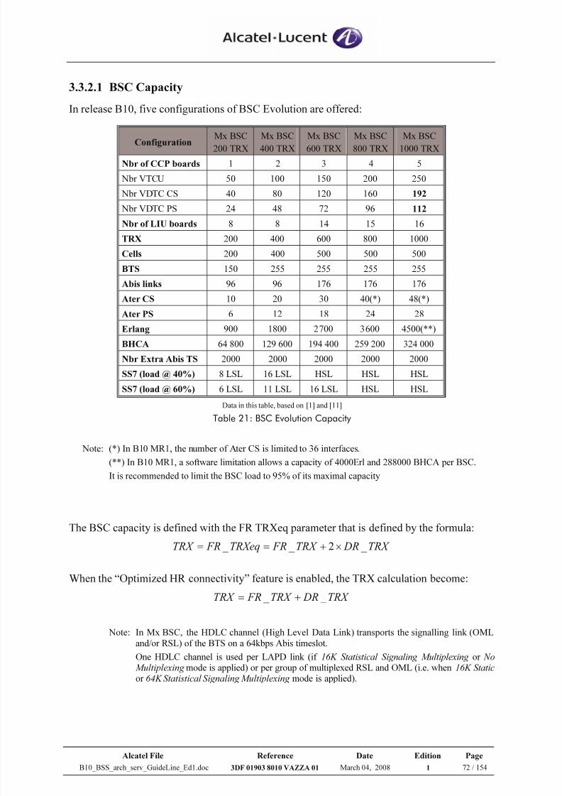
7/21/2019 BSS Architecture Service Guideline B10
http://slidepdf.com/reader/full/bss-architecture-service-guideline-b10 72/154
Alcatel File Reference Date Edition Page
B10_BSS_arch_serv_GuideLine_Ed1.doc 3DF 01903 8010 VAZZA 01 March 04, 2008 1 72 / 154
3.3.2.1 BSC Capacity
In release B10, five configurations of BSC Evolution are offered:
Configuration Mx BSC200 TRX
Mx BSC400 TRX
Mx BSC600 TRX
Mx BSC800 TRX
Mx BSC1000 TRX
Nbr of CCP boards 1 2 3 4 5
Nbr VTCU 50 100 150 200 250
Nbr VDTC CS 40 80 120 160 192
Nbr VDTC PS 24 48 72 96 112
Nbr of LIU boards 8 8 14 15 16
TRX 200 400 600 800 1000
Cells 200 400 500 500 500
BTS 150 255 255 255 255
Abis links 96 96 176 176 176
Ater CS 10 20 30 40(*) 48(*)
Ater PS 6 12 18 24 28
Erlang 900 1800 2700 3600 4500(**)
BHCA 64 800 129 600 194 400 259 200 324 000
Nbr Extra Abis TS 2000 2000 2000 2000 2000
SS7 (load @ 40%) 8 LSL 16 LSL HSL HSL HSL
SS7 (load @ 60%) 6 LSL 11 LSL 16 LSL HSL HSL
Data in this table, based on [1] and [11]
Table 21: BSC Evolution Capacity
Note: (*) In B10 MR1, the number of Ater CS is limited to 36 interfaces.
(**) In B10 MR1, a software limitation allows a capacity of 4000Erl and 288000 BHCA per BSC.
It is recommended to limit the BSC load to 95% of its maximal capacity
The BSC capacity is defined with the FR TRXeq parameter that is defined by the formula:
TRX DRTRX FRTRXeq FRTRX _ 2 _ _ ×+==
When the “Optimized HR connectivity” feature is enabled, the TRX calculation become:
TRX DRTRX FRTRX _ _ +=
Note: In Mx BSC, the HDLC channel (High Level Data Link) transports the signalling link (OML
and/or RSL) of the BTS on a 64kbps Abis timeslot.
One HDLC channel is used per LAPD link (if 16K Statistical Signaling Multiplexing or No Multiplexing mode is applied) or per group of multiplexed RSL and OML (i.e. when 16K Staticor 64K Statistical Signaling Multiplexing mode is applied).
7/21/2019 BSS Architecture Service Guideline B10
http://slidepdf.com/reader/full/bss-architecture-service-guideline-b10 73/154
Alcatel File Reference Date Edition Page
B10_BSS_arch_serv_GuideLine_Ed1.doc 3DF 01903 8010 VAZZA 01 March 04, 2008 1 73 / 154
Independently to the Mx BSC configuration, the TPGSMv1 board has a signalling limitation
of 512 HDLC channels, among which 441 are available for Abis signalling (RSL+OML).
Due to this limitation, an Mx BSC is not able to achieve the capacity of 1000 TRX in case a
lot of DR TREs are configured for that BSS.
With a normal signalling load , a HDLC channel handles 2 DR TRX or 4 FR TRX
=> 882 DR TRX per BSC
With a high signalling load , a HDLC channel handles 1 DR TRX or 2FR TRX
=> 441 DR TRX or 882 FR TRX per BSC
In order to reach the maximal load of TRX supported by Mx BSC, it is recommended to use
largely the 64K Statistical Multiplexing RSL mode.
In B10 MR2, the BSC performances are improved with the introduction of new TPGSMv3board.
This board allow a capacity of 1024 HDLC channels (984 channels are available for RSL and
OML), but the same maximum of 481 HDLC is retained initially in order to guarantee
transparent interoperability.
3.3.2.2 Delta BSC Evolution versus G2 BSC
For more details, please refer to [1]
3.3.2.3 CCP board
A CCP board contains several VTCUs and VDTC that corresponds respectively to TCU and
DTC software.
Thanks to the “TCU allocation Evolution” feature, several constraints existing in G2 BSC are
removed in A9130 BSC Evolution: all the VTCUs are managed as a pool where any Abis
signalling TS allocation can be routed to any TCU across CCPs boards.
Different Behaviors:
• TSU is removed
• Higher capacity: 1000 TRX / 500 cells
• 4500erl and SS7 High Speed Link
• No need of TCU to support extra Abis TS
• Removal of HR connectivity constraints
• Abis/Ater fixed mapping to LIU boards
Same Behaviors
• No change in logical model of the BSC
• No change in radio configurationmechanisms
• Same set of radio parameters
• Same set of PM counters/indicators asA9120 BSC
7/21/2019 BSS Architecture Service Guideline B10
http://slidepdf.com/reader/full/bss-architecture-service-guideline-b10 74/154
Alcatel File Reference Date Edition Page
B10_BSS_arch_serv_GuideLine_Ed1.doc 3DF 01903 8010 VAZZA 01 March 04, 2008 1 74 / 154
The feature considers the removal of TSU concept where in A9120 BSC during any
extension/reduction of a TRE/BTS, the TCU allocation for RSL/OML was done within a TSU
i.e. set of 8 TCUs.
With this feature TCU resource candidate is extended to all the TCUs irrespective of the CCP
boards i.e. not limited to 8 TCUs per TSU/BIUA as in A9120 BSC.
This also means that mapping between Abis & TCU will be replaced with free mapping of
any TRE to any TCU as per new TCU allocation algorithm.
We have the following benefits as far as removing this constraint is concerned:
• TCU resource allocation will become more flexible
• No need to perform reshuffling in any of the cases (i.e. TCU compact & SDCCH hot spot)
In A9130 BSC Evolution, TCU allocation will only involve the mapping of signalling
channels i.e. RSL/OML on a TCU. Since traffic will be switched within TPGSM so it doesnot make sense to map TCHs & EXTS on to the TCU.
Moreover TCU allocation algorithm for signalling links will be highly flexible as we can
allocated any available TCU from the TCU pool from configuration point view i.e. all TCUs
across CCP boards will belong to one pool.
Finally with the optional “Optimized HR connectivity”, the mapping constraints of DR TRX
are removed allowing full TRX connectivity at TCU level.
Rules
A VTCU can handle a maximum of:• 4 FR TREs (4 RSLs) or
• 2 FR + 1 DR TREs (3 RSLs) or
• 2 DR TREs (2 RSLs)
==> In other words TCU can handle maximum of 4 Eq. FR RSLs
• With “Optimized HR connectivity”, TCU handle 4 FR and/or DR RSL
• TCU can handle maximum of 3 OMLs.
• 7 LAPD per VTCU (for G2 BSC the limit is 6 LAPD per TCUC)
With these rules up to 200 TREs can be mapped on a CCP.
It shall be always possible to map up to four TREs (FR and/or DR) per VTCU.
The maximum number of TCH a CCP can handle shall be limited to MAX_TCH_PER_CCP,
parameter which is currently set to 1100 TCH sub-channels.
When the limit of MAX_TCH_PER_CCP parameter is reached, the TCH channels are
rejected.
The MC926 counter (TCH_Blocking_Occurrences_BSC) permits to detects the number of
rejected TCH if the CCP has reached its maximum processing capacity.
To avoid having unbalanced load between the CCP boards, it is requested to have a “remap-bts-on-ccp” command at the OMC-R to spread the load between the CCPs boards.
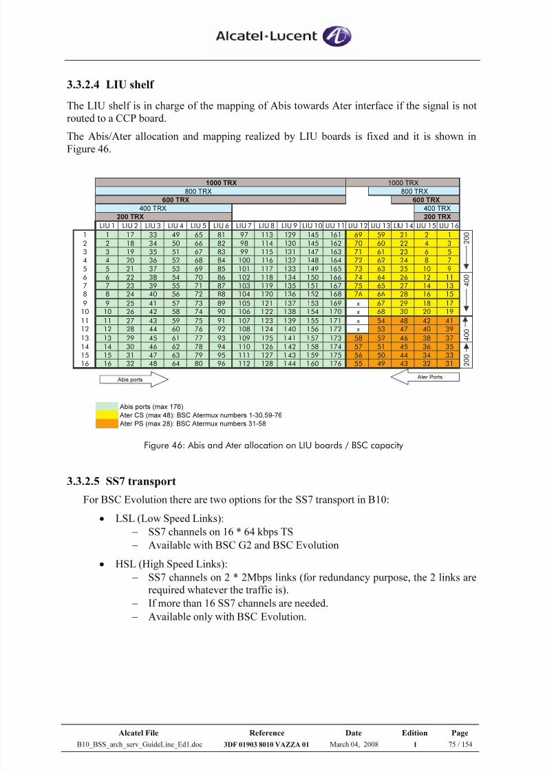
7/21/2019 BSS Architecture Service Guideline B10
http://slidepdf.com/reader/full/bss-architecture-service-guideline-b10 75/154
Alcatel File Reference Date Edition Page
B10_BSS_arch_serv_GuideLine_Ed1.doc 3DF 01903 8010 VAZZA 01 March 04, 2008 1 75 / 154
3.3.2.4 LIU shelf
The LIU shelf is in charge of the mapping of Abis towards Ater interface if the signal is not
routed to a CCP board.
The Abis/Ater allocation and mapping realized by LIU boards is fixed and it is shown inFigure 46.
1000 TRX
200 TRX
LIU 1 LIU 2 LIU 3 LIU 4 LIU 5 LIU 6 LIU 7 LIU 8 LIU 9 LIU 10 LIU 11 LIU 12 LIU 13 LIU 14 LIU 15 LIU 16
1 1 17 33 49 65 81 97 113 129 145 161 69 59 21 2 1
2 2 18 34 50 66 82 98 114 130 145 162 70 60 22 4 3
3 3 19 35 51 67 83 99 115 131 147 163 71 61 23 6 5
4 4 20 36 52 68 84 100 116 132 148 164 72 62 24 8 7
5 5 21 37 53 69 85 101 117 133 149 165 73 63 25 10 96 6 22 38 54 70 86 102 118 134 150 166 74 64 26 12 11
7 7 23 39 55 71 87 103 119 135 151 167 75 65 27 14 13
8 8 24 40 56 72 88 104 120 136 152 168 76 66 28 16 15
9 9 25 41 57 73 89 105 121 137 153 169 x 67 29 18 17
10 10 26 42 58 74 90 106 122 138 154 170 x 68 30 20 19
11 11 27 43 59 75 91 107 123 139 155 171 x 54 48 42 41
12 12 28 44 60 76 92 108 124 140 156 172 x 53 47 40 39
13 13 29 45 61 77 93 109 125 141 157 173 58 52 46 38 37
14 14 30 46 62 78 94 110 126 142 158 174 57 51 45 36 35
15 15 31 47 63 79 95 111 127 143 159 175 56 50 44 34 33
16 16 32 48 64 80 96 112 128 144 160 176 55 49 43 32 31
Abis ports (max 176) Ater CS (max 48): BSC Atermux numbers 1-30,59-76
Ater PS (max 28): BSC Atermux numbers 31-58
200 TRX
400 TRX 400 TRX
1000 TRX
600 TRX 600 TRX
800 TRX 800 TRX
2 0 0
4 0 0
4 0 0
2 0 0
Abis ports Ater Ports
Figure 46: Abis and Ater allocation on LIU boards / BSC capacity
3.3.2.5 SS7 transport
For BSC Evolution there are two options for the SS7 transport in B10:
• LSL (Low Speed Links):
− SS7 channels on 16 * 64 kbps TS
− Available with BSC G2 and BSC Evolution
• HSL (High Speed Links):
− SS7 channels on 2 * 2Mbps links (for redundancy purpose, the 2 links are
required whatever the traffic is).
− If more than 16 SS7 channels are needed.
− Available only with BSC Evolution.
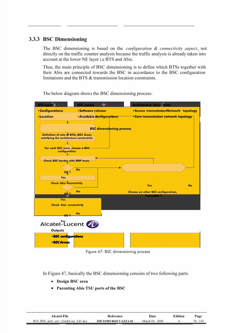
7/21/2019 BSS Architecture Service Guideline B10
http://slidepdf.com/reader/full/bss-architecture-service-guideline-b10 76/154
Alcatel File Reference Date Edition Page
B10_BSS_arch_serv_GuideLine_Ed1.doc 3DF 01903 8010 VAZZA 01 March 04, 2008 1 76 / 154
3.3.3 BSC Dimensioning
The BSC dimensioning is based on the configuration & connectivity aspect , not
directly on the traffic counter analysis because the traffic analysis is already taken into
account at the lower NE layer i.e BTS and Abis.
Thus, the main principle of BSC dimensioning is to define which BTSs together with
their Abis are connected towards the BSC in accordance to the BSC configuration
limitations and the BTS & transmission location constraints.
The below diagram shows the BSC dimensioning process:
BTS inputs
•Configurations
•Location
BSC dimensioning process
BSC inputs
•Software release
• Available configurations
Architecture Constraints
• Access transmissionNetwork topology
•Core transmission network topology
Definition of sets of BTSs (BSC Area)satisfying th e architecture constraints
For each BSC area, choose a BSCconfiguration
Check BSC border with RNP team
OK ?No
Check Abis connectivity
Yes
OK ?No Choose an other BSC configuration,
if possible ?
No Yes
Check Ater connectivity
OK ?No
Yes
Yes
Outputs
•BSC configurations
•BSC Areas
Figure 47: BSC dimensioning process
In Figure 47, basically the BSC dimensioning consists of two following parts:
• Design BSC area
• Parenting Abis TSU ports of the BSC
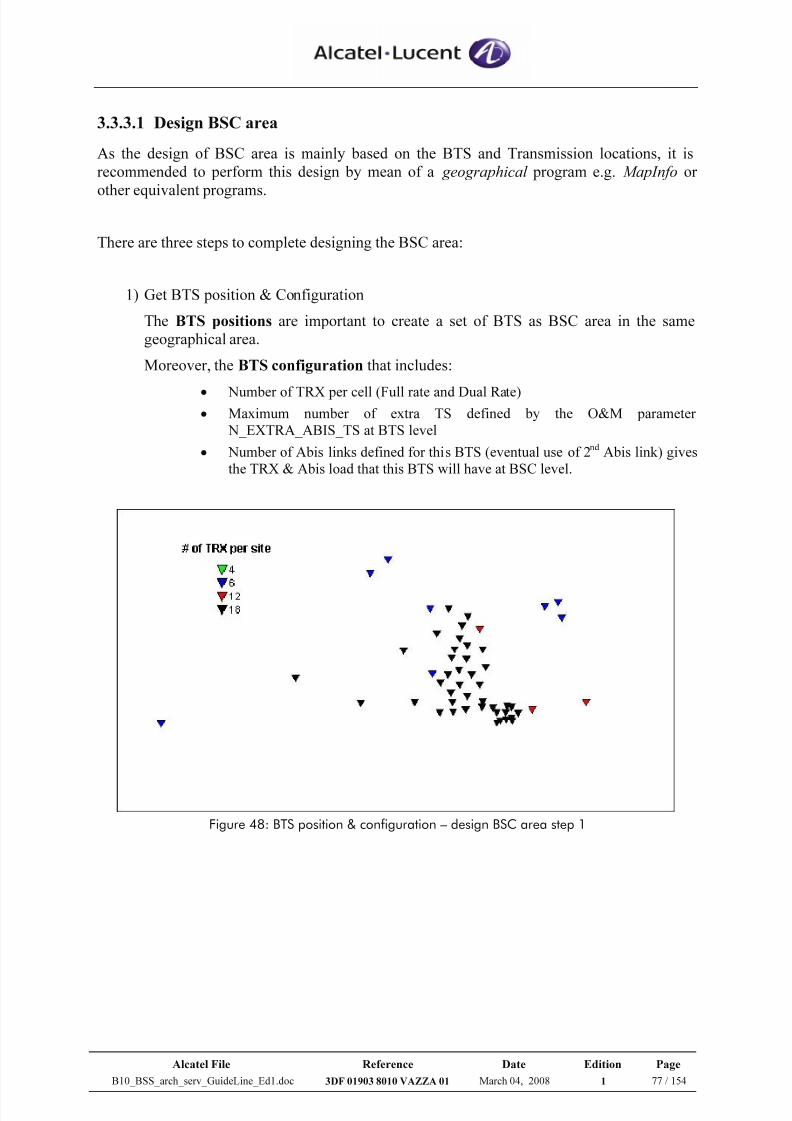
7/21/2019 BSS Architecture Service Guideline B10
http://slidepdf.com/reader/full/bss-architecture-service-guideline-b10 77/154
Alcatel File Reference Date Edition Page
B10_BSS_arch_serv_GuideLine_Ed1.doc 3DF 01903 8010 VAZZA 01 March 04, 2008 1 77 / 154
3.3.3.1 Design BSC area
As the design of BSC area is mainly based on the BTS and Transmission locations, it is
recommended to perform this design by mean of a geographical program e.g. MapInfo or
other equivalent programs.
There are three steps to complete designing the BSC area:
1) Get BTS position & Configuration
The BTS positions are important to create a set of BTS as BSC area in the same
geographical area.
Moreover, the BTS configuration that includes:
• Number of TRX per cell (Full rate and Dual Rate)• Maximum number of extra TS defined by the O&M parameter
N_EXTRA_ABIS_TS at BTS level
• Number of Abis links defined for this BTS (eventual use of 2nd Abis link) givesthe TRX & Abis load that this BTS will have at BSC level.
Figure 48: BTS position & configuration – design BSC area step 1
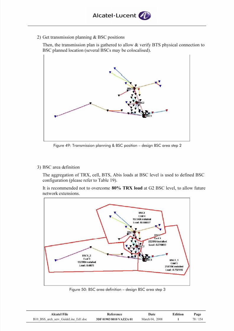
7/21/2019 BSS Architecture Service Guideline B10
http://slidepdf.com/reader/full/bss-architecture-service-guideline-b10 78/154
Alcatel File Reference Date Edition Page
B10_BSS_arch_serv_GuideLine_Ed1.doc 3DF 01903 8010 VAZZA 01 March 04, 2008 1 78 / 154
2) Get transmission planning & BSC positions
Then, the transmission plan is gathered to allow & verify BTS physical connection to
BSC planned location (several BSCs may be colocalised).
Figure 49: Transmission planning & BSC position – design BSC area step 2
3) BSC area definition
The aggregation of TRX, cell, BTS, Abis loads at BSC level is used to defined BSCconfiguration (please refer to Table 19).
It is recommended not to overcome 80% TRX load at G2 BSC level, to allow future
network extensions.
Figure 50: BSC area definition – design BSC area step 3
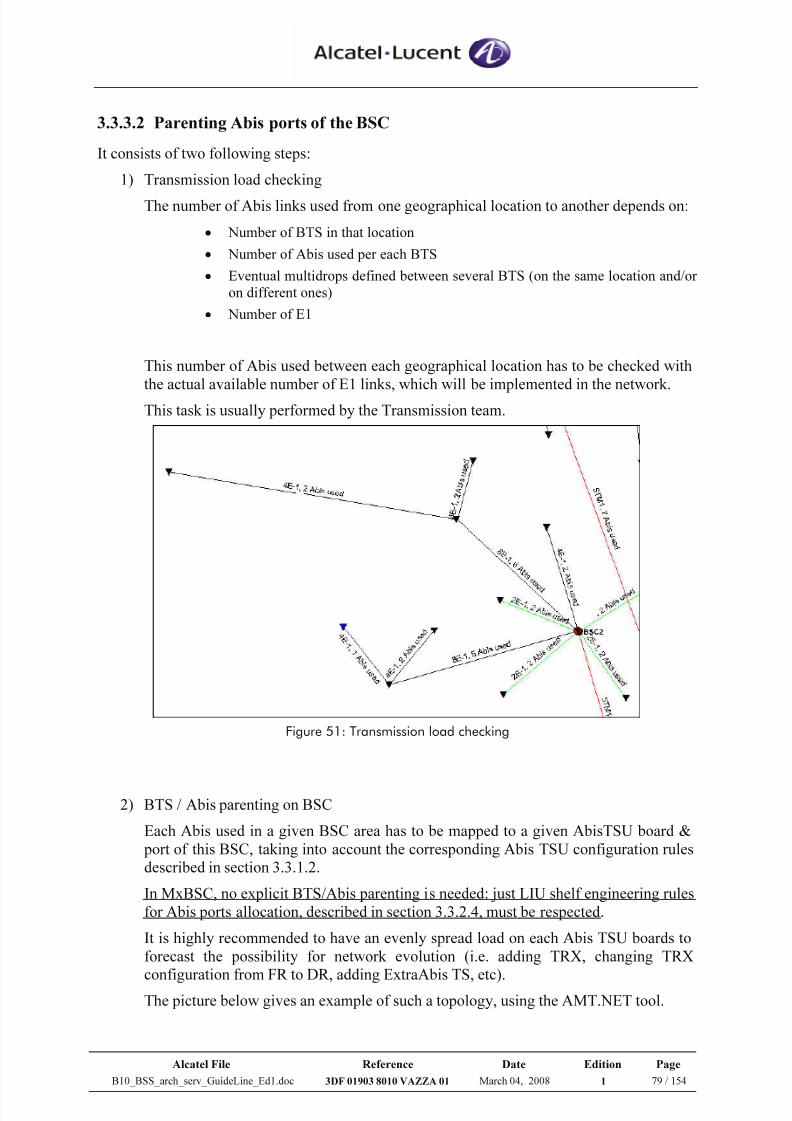
7/21/2019 BSS Architecture Service Guideline B10
http://slidepdf.com/reader/full/bss-architecture-service-guideline-b10 79/154
Alcatel File Reference Date Edition Page
B10_BSS_arch_serv_GuideLine_Ed1.doc 3DF 01903 8010 VAZZA 01 March 04, 2008 1 79 / 154
3.3.3.2 Parenting Abis ports of the BSC
It consists of two following steps:
1) Transmission load checking
The number of Abis links used from one geographical location to another depends on:
• Number of BTS in that location
• Number of Abis used per each BTS
• Eventual multidrops defined between several BTS (on the same location and/oron different ones)
• Number of E1
This number of Abis used between each geographical location has to be checked with
the actual available number of E1 links, which will be implemented in the network.
This task is usually performed by the Transmission team.
Figure 51: Transmission load checking
2) BTS / Abis parenting on BSC
Each Abis used in a given BSC area has to be mapped to a given AbisTSU board &
port of this BSC, taking into account the corresponding Abis TSU configuration rules
described in section 3.3.1.2.
In MxBSC, no explicit BTS/Abis parenting is needed: just LIU shelf engineering rules
for Abis ports allocation, described in section 3.3.2.4, must be respected.
It is highly recommended to have an evenly spread load on each Abis TSU boards to
forecast the possibility for network evolution (i.e. adding TRX, changing TRX
configuration from FR to DR, adding ExtraAbis TS, etc).The picture below gives an example of such a topology, using the AMT.NET tool.
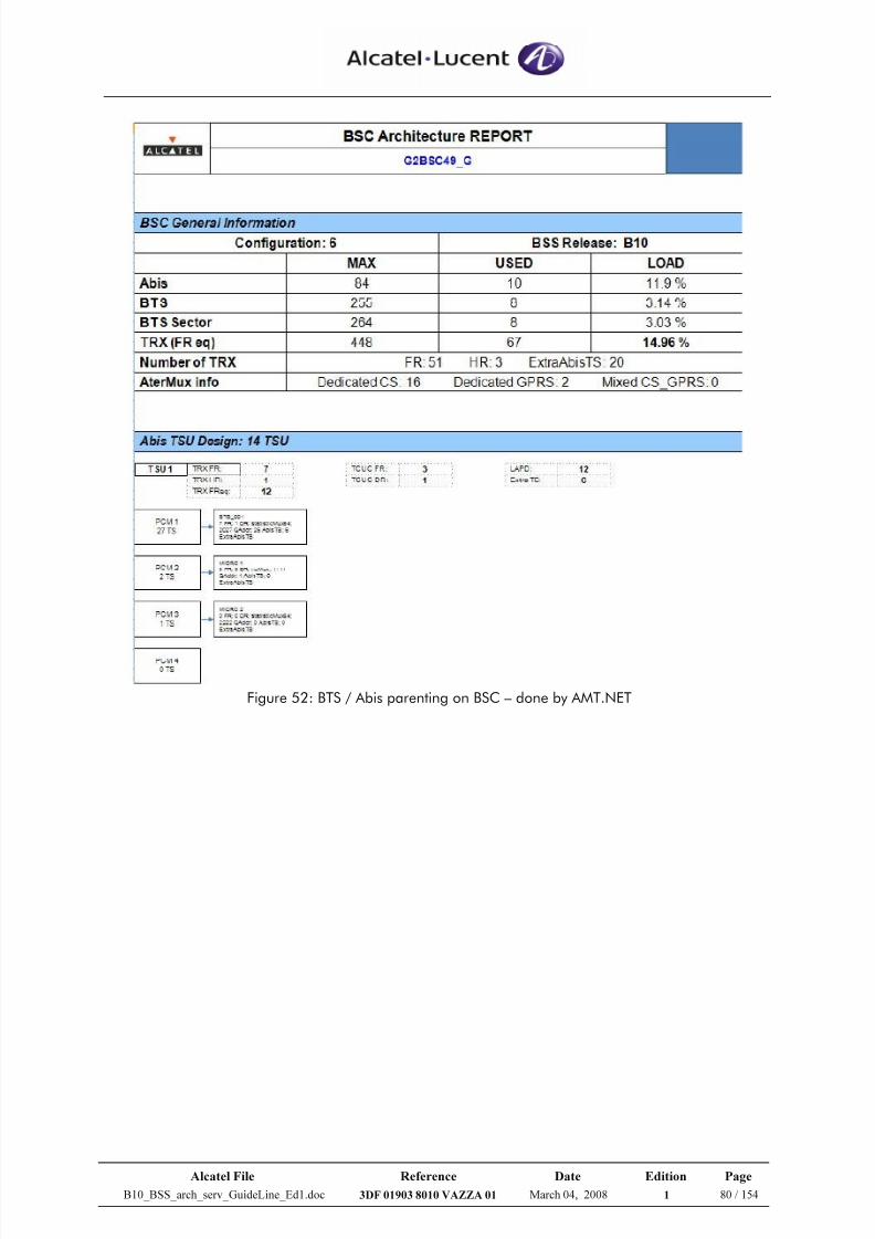
7/21/2019 BSS Architecture Service Guideline B10
http://slidepdf.com/reader/full/bss-architecture-service-guideline-b10 80/154
Alcatel File Reference Date Edition Page
B10_BSS_arch_serv_GuideLine_Ed1.doc 3DF 01903 8010 VAZZA 01 March 04, 2008 1 80 / 154
Figure 52: BTS / Abis parenting on BSC – done by AMT.NET
7/21/2019 BSS Architecture Service Guideline B10
http://slidepdf.com/reader/full/bss-architecture-service-guideline-b10 81/154
Alcatel File Reference Date Edition Page
B10_BSS_arch_serv_GuideLine_Ed1.doc 3DF 01903 8010 VAZZA 01 March 04, 2008 1 81 / 154
3.3.4 LA Dimensioning
Definition: A Location Area (LA) is the area in which a normal page for a particular
mobile, registered in this LA, will be broadcasted.
Too large LAs may lead to a too high paging load in the BTS resulting in congestion
and lost pages.
Smaller LAs reduce the paging load in the BTSs as well as in the BSCs. However, small
LA also means a larger number of LA border cells. Each time a mobile crosses the
boarder between two LAs, a location updating is performed. The LA update has an
effect on the load on the signalling sub-channels, SDCCH, in the LA border cells.
Target: The aim of LA dimensioning is to define the appropriate size of a Location
Area, which is mainly driven by the maximum number of paging the LA can handle, i.e.by the traffic seen on this Location Area.
Gathered Counters:
Counter Name Indicator Name Definition
MC8a GCCPGRQN Number of Paging message seen on Abis interface (PCH usage).
Table 22: Counter list – LA dimensioning
Note: the MC8a values for each cell in the same LA should be identical. However sometimes it wasobserved (from counters of live networks) that some cells in the same LA have the different MC8a value – for this case, the most frequency value will be chosen to be represented the paging traffic of the LA.
Measured Object: Cell
Gathering periods: 7-day Busy Hour data, recommended
Otherwise, at least 2 working -day Busy Hour data
Note: Busy Hour means the hour gives the highest paging traffic (i.e MC8a) of the day.
Methodology:
The maximum number of paging per Location Area is derived from the paging
limitations at Um interface, Abis Interface and BSC sides as following details.
• Um interface Limitation – Combined cells
There are 3 CCCH blocks per M51 frame for combined cells.
Among those 3 blocks, 3 minus BS_AG_BLK_RES are reserved for paging
(BS_AG_BLK_RES = 1 as an usual default value for combined cells).
A 2.5 Paging/PCH value has been used to derive the maximum paging load per
Location Area.
7/21/2019 BSS Architecture Service Guideline B10
http://slidepdf.com/reader/full/bss-architecture-service-guideline-b10 82/154
Alcatel File Reference Date Edition Page
B10_BSS_arch_serv_GuideLine_Ed1.doc 3DF 01903 8010 VAZZA 01 March 04, 2008 1 82 / 154
A value of 3 paging or even 4 paging per PCH can be reached if and only if:
High PCH load (> 80%). The (safe) engineering limit taken later makes likely that thisload is not reached. Indeed the CCCH capacity is not a linear function because of the paging request encoding method. Real time simulations performed internally show that
when the 3 Paging/PCH ratio is reached we usually have a high blocking rate on PCH(about 5%), which will induce repetition by the MSC.
Very good distribution of MS among all paging groups. This depends on the IMSIdistribution.
Therefore;
Available blocks for paging per hour:
2 PCH blocks/Multiframe * (3600s/ 235ms) = 30,638 PCH blocks/ hour
Note: 235 ms is the period of 51 Multiframe
Maximum paging per hour:
2.5 paging/Block * 30,638 Blocks = 76,595 paging/hour (100%load)
When 60% engineering limit is applied Alcatel recommendation
Recommended max paging per hour: 45,957 paging/hour
Recommended max paging per second: 12.76 paging/second
• Um interface Limitation – Non-combined cells
There are 9 CCCH blocks per 51 Multiframe for non-combined cells.
Among those 9 blocks, 9 minus BS_AG_BLK_RES are reserved for paging
(BS_AG_BLK_RES = 4 as an usual default value for non-combined cells).
The calculation is similar to the one related to combined cell above. The only difference
is a higher number of paging blocks per 51 Multiframe.
Therefore;
Available blocks for paging per hour:
5 PCH blocks/Multiframe * (3600s / 235 ms) = 76,595 PCH / hour
Maximum paging per hour:
2.5 paging/Block x 76,595 Blocks = 191,489 paging/hour (100%load)
When 60% engineering limit is applied Alcatel recommendation
Recommended max paging per hour: 114,893 paging/hour
Recommended max paging per second: 31.91 paging/second
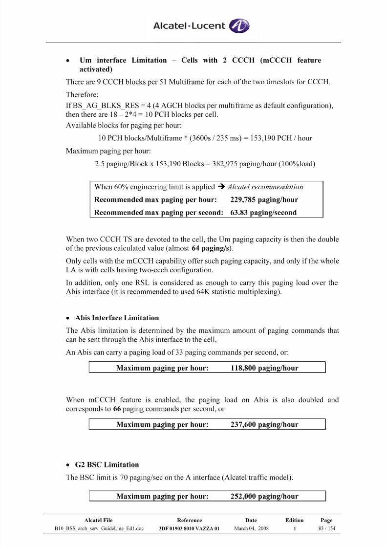
7/21/2019 BSS Architecture Service Guideline B10
http://slidepdf.com/reader/full/bss-architecture-service-guideline-b10 83/154
Alcatel File Reference Date Edition Page
B10_BSS_arch_serv_GuideLine_Ed1.doc 3DF 01903 8010 VAZZA 01 March 04, 2008 1 83 / 154
• Um interface Limitation – Cells with 2 CCCH (mCCCH feature
activated)
There are 9 CCCH blocks per 51 Multiframe for each of the two timeslots for CCCH.
Therefore;If BS_AG_BLKS_RES = 4 (4 AGCH blocks per multiframe as default configuration),
then there are 18 – 2*4 = 10 PCH blocks per cell.
Available blocks for paging per hour:
10 PCH blocks/Multiframe * (3600s / 235 ms) = 153,190 PCH / hour
Maximum paging per hour:
2.5 paging/Block x 153,190 Blocks = 382,975 paging/hour (100%load)
When 60% engineering limit is applied Alcatel recommendation
Recommended max paging per hour: 229,785 paging/hour
Recommended max paging per second: 63.83 paging/second
When two CCCH TS are devoted to the cell, the Um paging capacity is then the double
of the previous calculated value (almost 64 paging/s).
Only cells with the mCCCH capability offer such paging capacity, and only if the whole
LA is with cells having two-ccch configuration.
In addition, only one RSL is considered as enough to carry this paging load over the
Abis interface (it is recommended to used 64K statistic multiplexing).
• Abis Interface Limitation
The Abis limitation is determined by the maximum amount of paging commands that
can be sent through the Abis interface to the cell.
An Abis can carry a paging load of 33 paging commands per second, or:
Maximum paging per hour: 118,800 paging/hour
When mCCCH feature is enabled, the paging load on Abis is also doubled and
corresponds to 66 paging commands per second, or
Maximum paging per hour: 237,600 paging/hour
• G2 BSC Limitation
The BSC limit is 70 paging/sec on the A interface (Alcatel traffic model).
Maximum paging per hour: 252,000 paging/hour
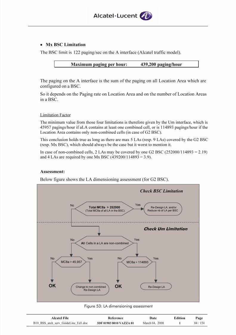
7/21/2019 BSS Architecture Service Guideline B10
http://slidepdf.com/reader/full/bss-architecture-service-guideline-b10 84/154
Alcatel File Reference Date Edition Page
B10_BSS_arch_serv_GuideLine_Ed1.doc 3DF 01903 8010 VAZZA 01 March 04, 2008 1 84 / 154
• Mx BSC Limitation
The BSC limit is 122 paging/sec on the A interface (Alcatel traffic model).
Maximum paging per hour: 439,200 paging/hour
The paging on the A interface is the sum of the paging on all Location Area which are
configured on a BSC.
So it depends on the Paging rate on Location Area and on the number of Location Areas
in a BSC.
Limitation Factor
The minimum value from those four limitations is therefore given by the Um interface, which is45957 pagings/hour if aLA contains at least one combined cell, or is 114893 pagings/hour if theLocation Area contains only non-combined cells (in case of G2 BSC).
This conclusion holds true as long as there are max 5 LAs (resp. 9 LAs) covered by the G2 BSC(resp. Mx BSC), which should always be the case but it worst to mention it.
In case of non-combined cells, 2 LAs may be covered by one G2 BSC (252000/114893 = 2.19)and 4 LAs are required by one Mx BSC (439200/114893 = 3.9).
Assessment:
Below figure shows the LA dimensioning assessment (for G2 BSC).
Total MC8a > 252000
(Total MC8a of all LA in the BSC)
Re-Design LA, and/or Reduce nb of LA per BSC
All Cells in a LA are non-combined
MC8a > 45,957 MC8a > 114893
Yes
No
No
No
NoYes Yes
Yes
OK OK Re-Design LAChange to non-combinedRe-Design LA
Check BSC Limitation
Check Um Limitation
Figure 53: LA dimensioning assessment
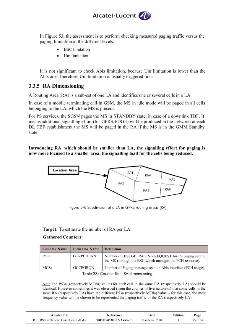
7/21/2019 BSS Architecture Service Guideline B10
http://slidepdf.com/reader/full/bss-architecture-service-guideline-b10 85/154
Alcatel File Reference Date Edition Page
B10_BSS_arch_serv_GuideLine_Ed1.doc 3DF 01903 8010 VAZZA 01 March 04, 2008 1 85 / 154
In Figure 53, the assessment is to perform checking measured paging traffic versus the
paging limitation at the different levels:
• BSC limitation
• Um limitation
It is not significant to check Abis limitation, because Um limitation is lower than the
Abis one. Therefore, Um limitation is usually triggered first.
3.3.5 RA Dimensioning
A Routing Area (RA) is a sub-set of one LA and identifies one or several cells in a LA.
In case of a mobile terminating call in GSM, the MS in idle mode will be paged in all cells
belonging to the LA, which the MS is present.
For PS services, the SGSN pages the MS in STANDBY state, in case of a downlink TBF. Itmeans additional signalling effort (for GPRS/EDGE) will be produced in the network: at each
DL TBF establishment the MS will be paged in the RA if the MS is in the GMM Standby
state.
Introducing RA, which should be smaller than LA, the signalling effort for paging is
now more focused to a smaller area, the signalling load for the cells being reduced.
Figure 54: Subdivision of a LA in GPRS routing areas (RA)
Target: To estimate the number of RA per LA.
Gathered Counters:
Counter Name Indicator Name Definition
P53a GTRPCHPAN Number of (BSCGP) PAGING REQUEST for PS paging sent tothe MS (through the BSC which manages the PCH resource).
MC8a GCCPGRQN Number of Paging message seen on Abis interface (PCH usage).
Table 23: Counter list – RA dimensioning
Note: the P53a (respectively MC8a) values for each cell in the same RA (respectively LA) should beidentical. However sometimes it was observed (from the counter of live networks) that some cells in thesame RA (respectively LA) have the different P53a (respectively MC8a) value – for this case, the mostfrequency value will be chosen to be represented the paging traffic of the RA (respectively LA).
7/21/2019 BSS Architecture Service Guideline B10
http://slidepdf.com/reader/full/bss-architecture-service-guideline-b10 86/154
Alcatel File Reference Date Edition Page
B10_BSS_arch_serv_GuideLine_Ed1.doc 3DF 01903 8010 VAZZA 01 March 04, 2008 1 86 / 154
Measured Object: Cell
Gathering periods: 7-day Busy Hour data, recommended
Otherwise, at least 2 working -day Busy Hour data
Note: Busy Hour means the hour gives the highest paging traffic (i.e. MC8a) of the day.
Methodology:
Main rule: RA size must be smaller than or equal to the LA size
It is not possible to define a RA across a LA border (e.g. one cell from LA1 and two
cells from LA2).
Other rules:
- One RA can contain one or several cells
- One cell cannot belong to two RA
- Cells from one BTS can be allocated to different RA
- The maximum number of RA in a LA is 256 (0, 1, 2... 255)
Some general remarks apply:
If the timer t_ready = high, MS doesn’t need to be paged too often so RA size can be as big asthe LA size.
But if t_ready = low, the RA size needs to be smaller than LA size.
The simple RA dimensioning, that is the RA size equals to LA size, is usually applied for theinitial RA area design.
However, it is recommended to perform afterward the RA dimensioning based on the GPRS paging traffic counter.
The main idea is to check whether the RA size is appropriate and not create the high ratio of GPRS paging traffic (P53a) when compared to the global paging (MC8a).
Otherwise, the smaller RA size may be needed to reduce the global paging load and to avoid PCH resource overload due to GPRS.
Note: GSM and GPRS services share the PCH (CCCH) resources (if the master channel feature is not
activated) in order to transport the paging traffic.
GPRS paging load ratio = P53a / MC8a
If this ratio is greater than 20% during the day hours, the solution to reduce global
paging load may be splitting RA into several RAs for a corresponding LA (one LA:
several RA).
Assessment:The limited GPRS paging load ratio can be modified.
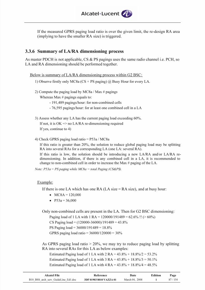
7/21/2019 BSS Architecture Service Guideline B10
http://slidepdf.com/reader/full/bss-architecture-service-guideline-b10 87/154
Alcatel File Reference Date Edition Page
B10_BSS_arch_serv_GuideLine_Ed1.doc 3DF 01903 8010 VAZZA 01 March 04, 2008 1 87 / 154
If the measured GPRS paging load ratio is over the given limit, the re-design RA area
(implying to have the smaller RA size) is triggered.
3.3.6 Summary of LA/RA dimensioning process
As master PDCH is not applicable, CS & PS pagings uses the same radio channel i.e. PCH, so
LA and RA dimensioning should be performed together.
Below is summary of LA/RA dimensioning process within G2 BSC:
1) Observe firstly only MC8a (CS + PS paging) @ Busy Hour for every LA.
2) Compute the paging load by MC8a / Max # pagings
Whereas Max # pagings equals to:
- 191,489 pagings/hour: for non-combined cells
- 76,595 pagings/hour: for at least one combined cell in a LA
3) Assess whether any LA has the current paging load exceeding 60%.
If not, it is OK => no LA/RA re-dimensioning required
If yes, continue to 4)
4) Check GPRS paging load ratio = P53a / MC8a
If this ratio is greater than 20%, the solution to reduce global paging load may be splittingRA into several RAs for a corresponding LA (one LA: several RA).
If this ratio is low, the solution should be introducing a new LA/RA and/or LA/RA re-dimensioning. In addition, if there is any combined cell in a LA, it is recommended tochange to non-combined cell in order to increase the Max # paging of the LA.
Note: P53a = PS paging while MC8a = total Paging (CS&PS).
Example:
If there is one LA which has one RA (LA size = RA size), and at busy hour:
• MC8A = 120,000
• P53a = 36,000
Only non-combined cells are present in the LA. Then for G2 BSC dimensioning:
Paging load of 1 LA with 1 RA = 120000/191489 = 62.6% !! (> 60%)
CS Paging load = (120000-36000)/191489 = 43.8%
PS Paging load = 36000/191489 = 18.8%
GPRS paging load ratio = 36000/120000 = 30%
As GPRS paging load ratio > 20%, we may try to reduce paging load by splitting
RA into several RAs for this LA as below examples:
Estimated Paging load of 1 LA with 2 RA = 43.8% + 18.8%/2 = 53.2%Estimated Paging load of 1 LA with 3 RA = 43.8% + 18.8%/3 = 50.1%
Estimated Paging load of 1 LA with 4 RA = 43.8% + 18.8%/4 = 48.5%
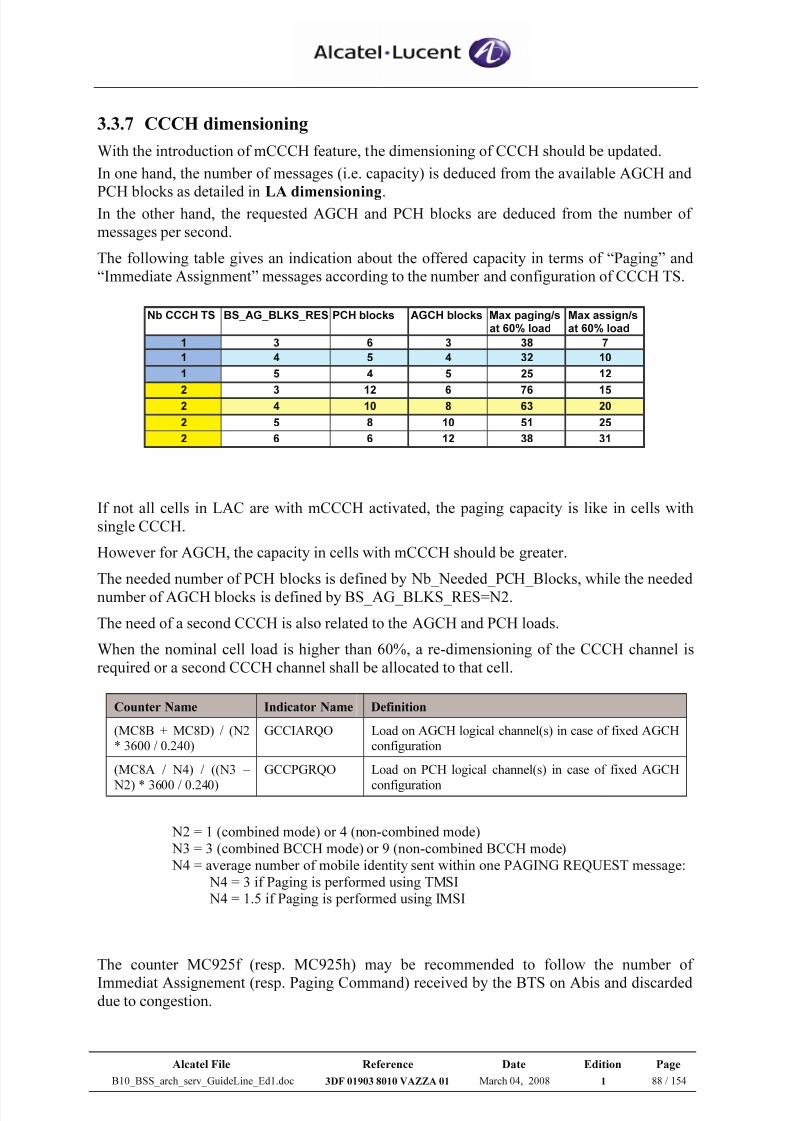
7/21/2019 BSS Architecture Service Guideline B10
http://slidepdf.com/reader/full/bss-architecture-service-guideline-b10 88/154
Alcatel File Reference Date Edition Page
B10_BSS_arch_serv_GuideLine_Ed1.doc 3DF 01903 8010 VAZZA 01 March 04, 2008 1 88 / 154
3.3.7 CCCH dimensioning
With the introduction of mCCCH feature, the dimensioning of CCCH should be updated.
In one hand, the number of messages (i.e. capacity) is deduced from the available AGCH and
PCH blocks as detailed in LA dimensioning.In the other hand, the requested AGCH and PCH blocks are deduced from the number of
messages per second.
The following table gives an indication about the offered capacity in terms of “Paging” and
“Immediate Assignment” messages according to the number and configuration of CCCH TS.
Nb CCCH TS BS_AG_BLKS_RES PCH blocks AGCH blocks Max paging/sat 60% load
Max assign/sat 60% load
1 3 6 3 38 7
1 4 5 4 32 10
1 5 4 5 25 12
2 3 12 6 76 152 4 10 8 63 20
2 5 8 10 51 25
2 6 6 12 38 31
If not all cells in LAC are with mCCCH activated, the paging capacity is like in cells with
single CCCH.
However for AGCH, the capacity in cells with mCCCH should be greater.
The needed number of PCH blocks is defined by Nb_Needed_PCH_Blocks, while the needed
number of AGCH blocks is defined by BS_AG_BLKS_RES=N2.
The need of a second CCCH is also related to the AGCH and PCH loads.
When the nominal cell load is higher than 60%, a re-dimensioning of the CCCH channel is
required or a second CCCH channel shall be allocated to that cell.
Counter Name Indicator Name Definition
(MC8B + MC8D) / (N2* 3600 / 0.240)
GCCIARQO Load on AGCH logical channel(s) in case of fixed AGCHconfiguration
(MC8A / N4) / ((N3 –
N2) * 3600 / 0.240)
GCCPGRQO Load on PCH logical channel(s) in case of fixed AGCH
configuration
N2 = 1 (combined mode) or 4 (non-combined mode) N3 = 3 (combined BCCH mode) or 9 (non-combined BCCH mode) N4 = average number of mobile identity sent within one PAGING REQUEST message:
N4 = 3 if Paging is performed using TMSI N4 = 1.5 if Paging is performed using IMSI
The counter MC925f (resp. MC925h) may be recommended to follow the number of
Immediat Assignement (resp. Paging Command) received by the BTS on Abis and discardeddue to congestion.
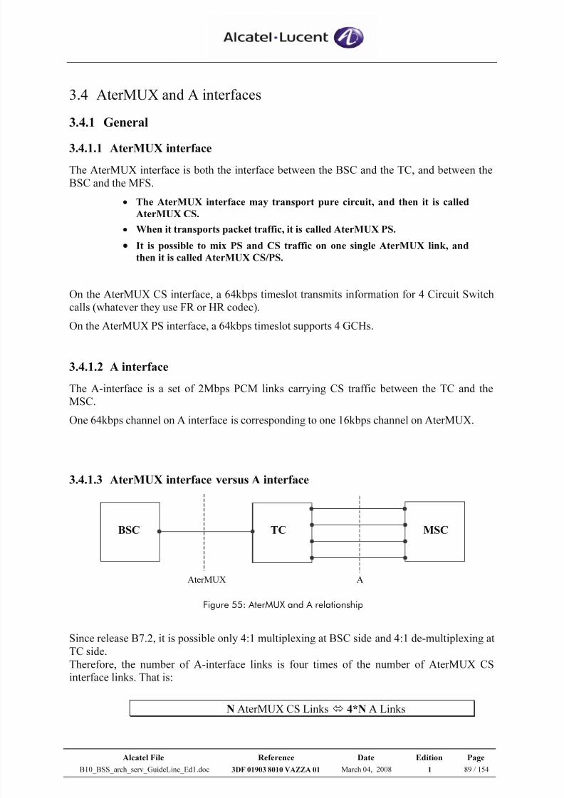
7/21/2019 BSS Architecture Service Guideline B10
http://slidepdf.com/reader/full/bss-architecture-service-guideline-b10 89/154
Alcatel File Reference Date Edition Page
B10_BSS_arch_serv_GuideLine_Ed1.doc 3DF 01903 8010 VAZZA 01 March 04, 2008 1 89 / 154
3.4 AterMUX and A interfaces
3.4.1 General
3.4.1.1 AterMUX interface
The AterMUX interface is both the interface between the BSC and the TC, and between the
BSC and the MFS.
• The AterMUX interface may transport pure circuit, and then it is called
AterMUX CS.
• When it transports packet traffic, it is called AterMUX PS.
• It is possible to mix PS and CS traffic on one single AterMUX link, and
then it is called AterMUX CS/PS.
On the AterMUX CS interface, a 64kbps timeslot transmits information for 4 Circuit Switch
calls (whatever they use FR or HR codec).
On the AterMUX PS interface, a 64kbps timeslot supports 4 GCHs.
3.4.1.2 A interface
The A-interface is a set of 2Mbps PCM links carrying CS traffic between the TC and the
MSC.
One 64kbps channel on A interface is corresponding to one 16kbps channel on AterMUX.
3.4.1.3 AterMUX interface versus A interface
TCBSC MSC
AterMUX A
Figure 55: AterMUX and A relationship
Since release B7.2, it is possible only 4:1 multiplexing at BSC side and 4:1 de-multiplexing at
TC side.
Therefore, the number of A-interface links is four times of the number of AterMUX CS
interface links. That is:
N AterMUX CS Links 4*N A Links
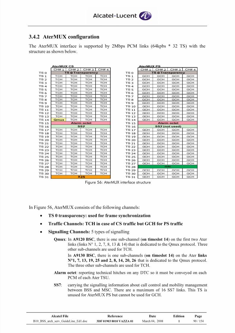
7/21/2019 BSS Architecture Service Guideline B10
http://slidepdf.com/reader/full/bss-architecture-service-guideline-b10 90/154
Alcatel File Reference Date Edition Page
B10_BSS_arch_serv_GuideLine_Ed1.doc 3DF 01903 8010 VAZZA 01 March 04, 2008 1 90 / 154
3.4.2 AterMUX configuration
The AterMUX interface is supported by 2Mbps PCM links (64kpbs * 32 TS) with the
structure as shown below.
AterMUX CS AterMUX PS
CH# 1 CH# 2 CH# 3 CH# 4 CH# 1 CH# 2 CH# 3 CH# 4
TS 0 TS 0
TS 1 TCH TCH TCH TCH TS 1 GCH GCH GCH GCH
TS 2 TCH TCH TCH TCH TS 2 GCH GCH GCH GCH
TS 3 TCH TCH TCH TCH TS 3 GCH GCH GCH GCH
TS 4 TCH TCH TCH TCH TS 4 GCH GCH GCH GCH
TS 5 TCH TCH TCH TCH TS 5 GCH GCH GCH GCH
TS 6 TCH TCH TCH TCH TS 6 GCH GCH GCH GCH
TS 7 TCH TCH TCH TCH TS 7 GCH GCH GCH GCH
TS 8 TCH TCH TCH TCH TS 8 GCH GCH GCH GCH
TS 9 TCH TCH TCH TCH TS 9 GCH GCH GCH GCH
TS 10 TCH TCH TCH TCH TS 10 GCH GCH GCH GCH
TS 11 TCH TCH TCH TCH TS 11 GCH GCH GCH GCH
TS 12 TCH TCH TCH TCH TS 12 GCH GCH GCH GCH
TS 13 TCH TCH TCH TCH TS 13 GCH GCH GCH GCH
TS 14 Qmux TCH TCH TCH TS 14 GCH GCH GCH GCH
TS 15 TS 15
TS 16 TS 16
TS 17 TCH TCH TCH TCH TS 17 GCH GCH GCH GCH
TS 18 TCH TCH TCH TCH TS 18 GCH GCH GCH GCH
TS 19 TCH TCH TCH TCH TS 19 GCH GCH GCH GCH
TS 20 TCH TCH TCH TCH TS 20 GCH GCH GCH GCH
TS 21 TCH TCH TCH TCH TS 21 GCH GCH GCH GCH
TS 22 TCH TCH TCH TCH TS 22 GCH GCH GCH GCH
TS 23 TCH TCH TCH TCH TS 23 GCH GCH GCH GCH
TS 24 TCH TCH TCH TCH TS 24 GCH GCH GCH GCH
TS 25 TCH TCH TCH TCH TS 25 GCH GCH GCH GCH
TS 26 TCH TCH TCH TCH TS 26 GCH GCH GCH GCH
TS 27 TCH TCH TCH TCH TS 27 GCH GCH GCH GCH
TS 28 TCH TCH TCH TCH TS 28
TS 29 TCH TCH TCH TCH TS 29 GCH GCH GCH GCH
TS 30 TCH TCH TCH TCH TS 30 GCH GCH GCH GCH
TS 31 TS 31 GCH GCH GCH GCH
TS 0Transparency
Alarm octet
SS7 (not used)
GSL
Alarm octet
SS7
X25
TS 0Transparency
Figure 56: AterMUX interface structure
In Figure 56, AterMUX consists of the following channels:
• TS 0 transparency: used for frame synchronization
• Traffic Channels: TCH in case of CS traffic but GCH for PS traffic
•
Signalling Channels: 5 types of signalling Qmux: In A9120 BSC, there is one sub-channel (on timeslot 14) on the first two Ater
links (links N° 1, 2, 7, 8, 13 & 14) that is dedicated to the Qmux protocol. Threeother sub-channels are used for TCH.
In A9130 BSC, there is one sub-channels (on timeslot 14) on the Ater links
N°1, 7, 13, 19, 25 and 2, 8, 14, 20, 26 that is dedicated to the Qmux protocol.The three other sub-channels are used for TCH.
Alarm octet: reporting technical hitches on any DTC so it must be conveyed on eachPCM of each Ater TSU.
SS7: carrying the signalling information about call control and mobility management
between BSS and MSC. There are a maximum of 16 SS7 links. This TS isunused for AterMUX PS but cannot be used for GCH.
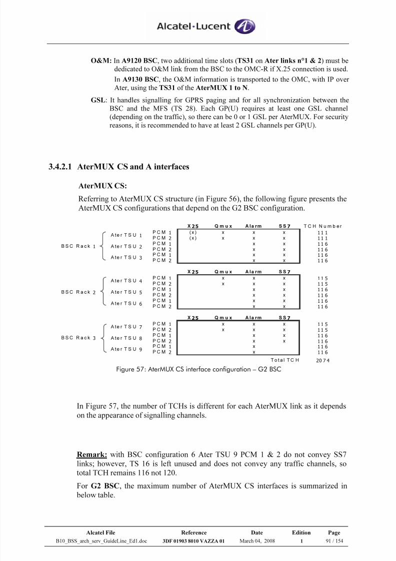
7/21/2019 BSS Architecture Service Guideline B10
http://slidepdf.com/reader/full/bss-architecture-service-guideline-b10 91/154
Alcatel File Reference Date Edition Page
B10_BSS_arch_serv_GuideLine_Ed1.doc 3DF 01903 8010 VAZZA 01 March 04, 2008 1 91 / 154
O&M: In A9120 BSC, two additional time slots (TS31 on Ater links n°1 & 2) must bededicated to O&M link from the BSC to the OMC-R if X.25 connection is used.
In A9130 BSC, the O&M information is transported to the OMC, with IP overAter, using the TS31 of the AterMUX 1 to N.
GSL: It handles signalling for GPRS paging and for all synchronization between theBSC and the MFS (TS 28). Each GP(U) requires at least one GSL channel(depending on the traffic), so there can be 0 or 1 GSL per AterMUX. For securityreasons, it is recommended to have at least 2 GSL channels per GP(U).
3.4.2.1 AterMUX CS and A interfaces
AterMUX CS:
Referring to AterMUX CS structure (in Figure 56), the following figure presents theAterMUX CS configurations that depend on the G2 BSC configuration.
X 25 Q m u x A l a r m S S 7 T C H N u m b e r
P C M 1 ( x ) x x x 1 1 1
P C M 2 ( x ) x x x 1 1 1
P C M 1 x x 1 1 6
P C M 2 x x 1 1 6
P C M 1 x x 1 1 6
P C M 2 x x 1 1 6
X 25 Q m u x A l a r m S S 7
P C M 1 x x x 1 1 5
P C M 2 x x x 1 1 5
P C M 1 x x 1 1 6
P C M 2 x x 1 1 6P C M 1 x x 1 1 6
P C M 2 x x 1 1 6
X 25 Q m u x A l a r m S S 7
P C M 1 x x x 1 1 5
P C M 2 x x x 1 1 5
P C M 1 x x 1 1 6
P C M 2 x x 1 1 6
P C M 1 x 1 1 6
P C M 2 x 1 1 6
T o t a l T C H 20 7 4
A te r T S U 9
B S C R a c k 1
B S C R a c k 2
B S C R a c k 3
A te r T S U 5
A te r T S U 6
A te r T S U 7
A te r T S U 8
A te r T S U 1
A te r T S U 2
A te r T S U 3
A te r T S U 4
Figure 57: AterMUX CS interface configuration – G2 BSC
In Figure 57, the number of TCHs is different for each AterMUX link as it depends
on the appearance of signalling channels.
Remark: with BSC configuration 6 Ater TSU 9 PCM 1 & 2 do not convey SS7
links; however, TS 16 is left unused and does not convey any traffic channels, so
total TCH remains 116 not 120.
For G2 BSC, the maximum number of AterMUX CS interfaces is summarized in
below table.
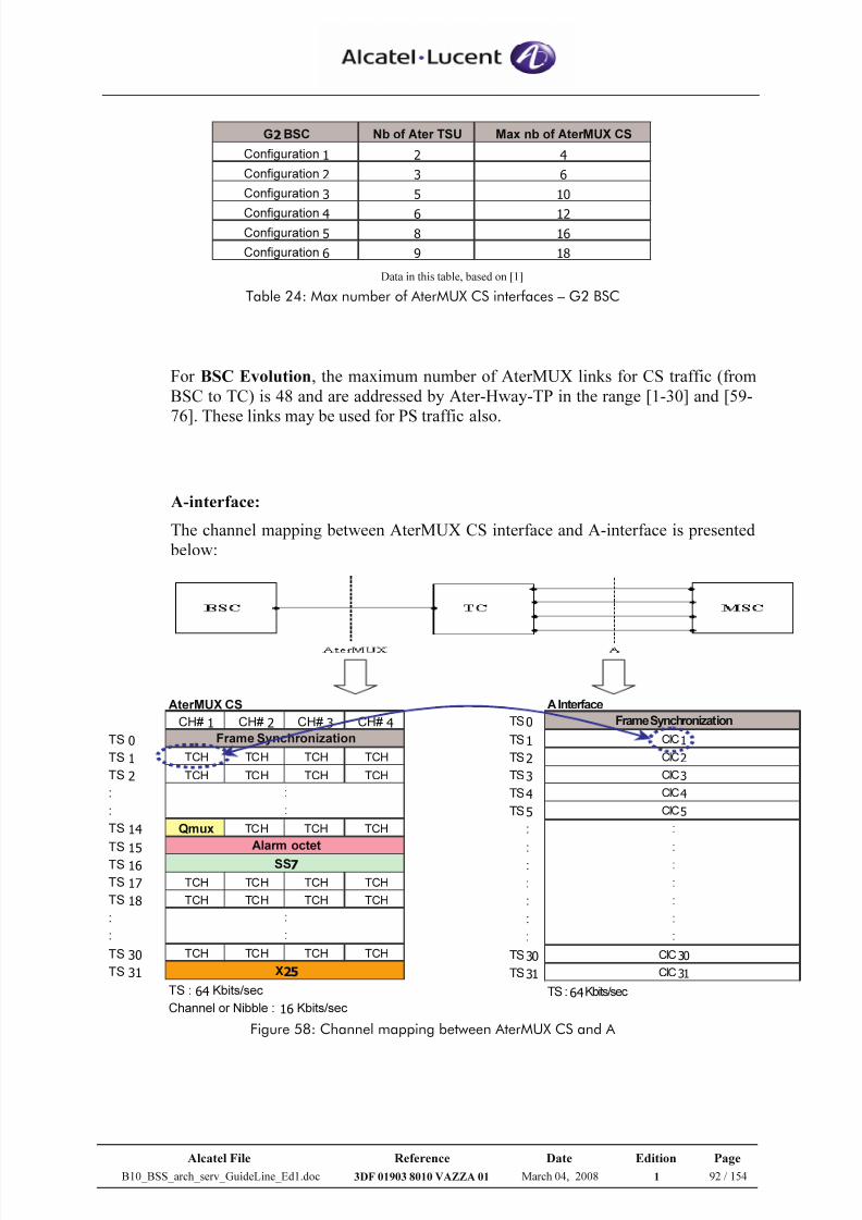
7/21/2019 BSS Architecture Service Guideline B10
http://slidepdf.com/reader/full/bss-architecture-service-guideline-b10 92/154
Alcatel File Reference Date Edition Page
B10_BSS_arch_serv_GuideLine_Ed1.doc 3DF 01903 8010 VAZZA 01 March 04, 2008 1 92 / 154
G2BSC Nb of Ater TSU Max nb of AterMUX CS
Configuration 1 2 4
Configuration 2 3 6
Configuration 3 5 10
Configuration 4 6 12
Configuration 5 8 16
Configuration 6 9 18 Data in this table, based on [1]
Table 24: Max number of AterMUX CS interfaces – G2 BSC
For BSC Evolution, the maximum number of AterMUX links for CS traffic (from
BSC to TC) is 48 and are addressed by Ater-Hway-TP in the range [1-30] and [59-
76]. These links may be used for PS traffic also.
A-interface:
The channel mapping between AterMUX CS interface and A-interface is presented
below:
AterMUX CS
CH# 1 CH# 2 CH# 3 CH# 4
TS 0
TS 1 TCH TCH TCH TCH
TS 2 TCH TCH TCH TCH
:
:
TS 14 Qmux TCH TCH TCH
TS 15
TS 16
TS 17 TCH TCH TCH TCH
TS 18 TCH TCH TCH TCH
:
:
TS 30 TCH TCH TCH TCH
TS 31
TS : 64 Kbits/sec
Channel or Nibble : 16 Kbits/sec
Frame Synchronization
Alarm octet
SS7
X25
:
:
:
:
A Interface
TS0
TS1
TS2
TS3
TS4
TS5
:
:
:
:
:
:
:
TS30
TS31
TS : 64Kbits/sec
Frame Synchronization
CIC31
CIC4
CIC5
:
:
:
:
:
:
CIC30
CIC1
CIC2
CIC3
:
Figure 58: Channel mapping between AterMUX CS and A
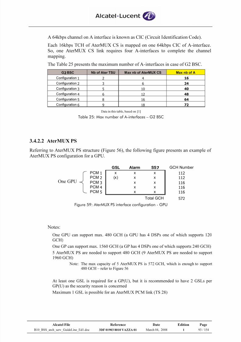
7/21/2019 BSS Architecture Service Guideline B10
http://slidepdf.com/reader/full/bss-architecture-service-guideline-b10 93/154
Alcatel File Reference Date Edition Page
B10_BSS_arch_serv_GuideLine_Ed1.doc 3DF 01903 8010 VAZZA 01 March 04, 2008 1 93 / 154
A 64kbps channel on A interface is known as CIC (Circuit Identification Code).
Each 16kbps TCH of AterMUX CS is mapped on one 64kbps CIC of A-interface.
So, one AterMUX CS link requires four A-interfaces to complete the channel
mapping.
The Table 25 presents the maximum number of A-interfaces in case of G2 BSC.
G2BSC Nb of Ater TSU Max nb of AterMUX CS Max nb of A
Configuration 1 2 4 16
Configuration 2 3 6 24
Configuration 3 5 10 40
Configuration 4 6 12 48
Configuration 5 8 16 64
Configuration 6 9 18 72 Data in this table, based on [1]
Table 25: Max number of A-interfaces – G2 BSC
3.4.2.2 AterMUX PS
Referring to AterMUX PS structure (Figure 56), the following figure presents an example of
AterMUX PS configuration for a GPU.
One GPU
GSL Alarm SS7 GCH Number
PCM 1 x x x 112
PCM 2 (x) x x 112
PCM 3 x x 116
PCM 4 x x 116
PCM 5 x x 116
Total GCH 572 Figure 59: AterMUX PS interface configuration - GPU
Notes:
One GPU can support max. 480 GCH (a GPU has 4 DSPs one of which supports 120
GCH)One GP can support max. 1560 GCH (a GP has 4 DSPs one of which supports 240 GCH)
5 AterMUX PS are needed to support 480 GCH (9 AterMUX PS are needed to support
1960 GCH)
Note: The max capacity of 5 AterMUX PS is 572 GCH, which is enough to support480 GCH – refer to Figure 56
At least one GSL is required for a GP(U), but it is recommended to have 2 GSLs per
GP(U) as the security reason is concerned
Maximum 1 GSL is possible for an AterMUX PCM link (TS 28)
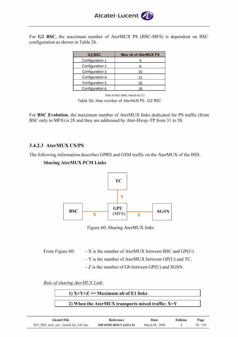
7/21/2019 BSS Architecture Service Guideline B10
http://slidepdf.com/reader/full/bss-architecture-service-guideline-b10 94/154
Alcatel File Reference Date Edition Page
B10_BSS_arch_serv_GuideLine_Ed1.doc 3DF 01903 8010 VAZZA 01 March 04, 2008 1 94 / 154
For G2 BSC, the maximum number of AterMUX PS (BSC-MFS) is dependent on BSC
configuration as shown in Table 26.
G2BSC Max nb of AterMUX PS
Configuration 1 4
Configuration 2 6
Configuration 3 10
Configuration 4 12
Configuration 5 16
Configuration 6 18 Data in this table, based on [1]
Table 26: Max number of AterMUX PS– G2 BSC
For BSC Evolution, the maximum number of AterMUX links dedicated for PS traffic (from
BSC only to MFS) is 28 and they are addressed by Ater-Hway-TP from 31 to 58.
3.4.2.3 AterMUX CS/PS
The following information describes GPRS and GSM traffic on the AterMUX of the BSS .
Sharing AterMUX PCM Links
Figure 60: Sharing AterMUX links
From Figure 60: - X is the number of AterMUX between BSC and GP(U).
- Y is the number of AterMUX between GP(U) and TC.
- Z is the number of Gb between GP(U) and SGSN.
Rule of sharing AterMUX Link:
1) X+Y+Z <= Maximum nb of E1 links
2) When the AterMUX transports mixed traffic: X=Y
BSC GPU
(MFS)
TC
SGSN X
Y
Z
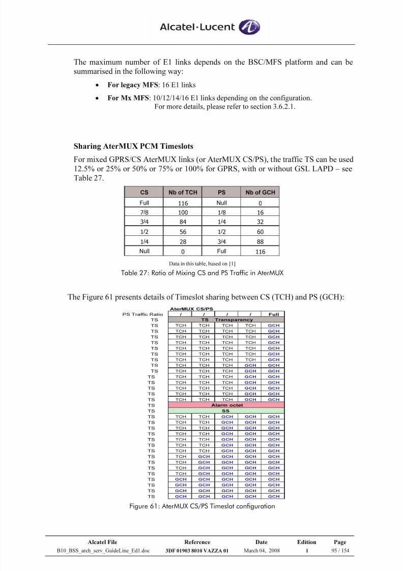
7/21/2019 BSS Architecture Service Guideline B10
http://slidepdf.com/reader/full/bss-architecture-service-guideline-b10 95/154
Alcatel File Reference Date Edition Page
B10_BSS_arch_serv_GuideLine_Ed1.doc 3DF 01903 8010 VAZZA 01 March 04, 2008 1 95 / 154
The maximum number of E1 links depends on the BSC/MFS platform and can be
summarised in the following way:
• For legacy MFS: 16 E1 links
•
For Mx MFS: 10/12/14/16 E1 links depending on the configuration.For more details, please refer to section 3.6.2.1.
Sharing AterMUX PCM Timeslots
For mixed GPRS/CS AterMUX links (or AterMUX CS/PS), the traffic TS can be used
12.5% or 25% or 50% or 75% or 100% for GPRS, with or without GSL LAPD – see
Table 27.
CS Nb of TCH PS Nb of GCH
Full 116 Null 0
7/8 100 1/8 16
3/4 84 1/4 32
1/2 56 1/2 60
1/4 28 3/4 88
Null 0 Full 116 Data in this table, based on [1]
Table 27: Ratio of Mixing CS and PS Traffic in AterMUX
The Figure 61 presents details of Timeslot sharing between CS (TCH) and PS (GCH):
PS Traffic Ratio / / / / Full
TS
TS TCH TCH TCH TCH GCH
TS TCH TCH TCH TCH GCH
TS TCH TCH TCH TCH GCH
TS TCH TCH TCH TCH GCH
TS TCH TCH TCH TCH GCH
TS TCH TCH TCH TCH GCH
TS TCH TCH TCH TCH GCH
TS TCH TCH TCH GCH GCH
TS TCH TCH TCH GCH GCH
TS TCH TCH TCH GCH GCH
TS TCH TCH TCH GCH GCH
TS TCH TCH TCH GCH GCH
TS TCH TCH TCH GCH GCH
TS TCH TCH TCH GCH GCH
TS
TS
TS TCH TCH GCH GCH GCH
TS TCH TCH GCH GCH GCH
TS TCH TCH GCH GCH GCH
TS TCH TCH GCH GCH GCH
TS TCH TCH GCH GCH GCH
TS TCH TCH GCH GCH GCH
TS TCH TCH GCH GCH GCH
TS TCH GCH GCH GCH GCH
TS TCH GCH GCH GCH GCH
TS TCH GCH GCH GCH GCH
TS TCH GCH GCH GCH GCH
TS GCH GCH GCH GCH GCH
TS GCH GCH GCH GCH GCH
TS GCH GCH GCH GCH GCH
TS GCH GCH GCH GCH GCH
AterMUX CS/PS
TS Transparency
Alarm octet
SS
Figure 61: AterMUX CS/PS Timeslot configuration
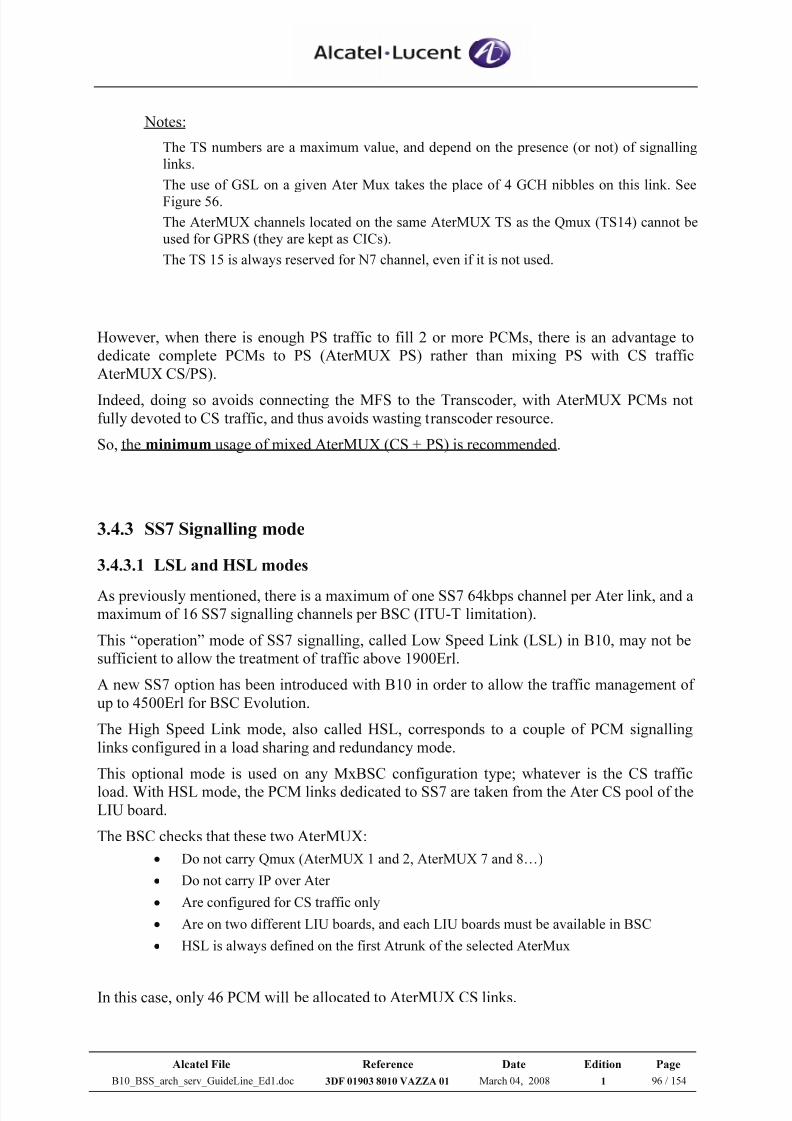
7/21/2019 BSS Architecture Service Guideline B10
http://slidepdf.com/reader/full/bss-architecture-service-guideline-b10 96/154
Alcatel File Reference Date Edition Page
B10_BSS_arch_serv_GuideLine_Ed1.doc 3DF 01903 8010 VAZZA 01 March 04, 2008 1 96 / 154
Notes:
The TS numbers are a maximum value, and depend on the presence (or not) of signalling
links.
The use of GSL on a given Ater Mux takes the place of 4 GCH nibbles on this link. See
Figure 56.
The AterMUX channels located on the same AterMUX TS as the Qmux (TS14) cannot be
used for GPRS (they are kept as CICs).
The TS 15 is always reserved for N7 channel, even if it is not used.
However, when there is enough PS traffic to fill 2 or more PCMs, there is an advantage to
dedicate complete PCMs to PS (AterMUX PS) rather than mixing PS with CS traffic
AterMUX CS/PS).
Indeed, doing so avoids connecting the MFS to the Transcoder, with AterMUX PCMs not
fully devoted to CS traffic, and thus avoids wasting transcoder resource.
So, the minimum usage of mixed AterMUX (CS + PS) is recommended.
3.4.3 SS7 Signalling mode
3.4.3.1 LSL and HSL modes
As previously mentioned, there is a maximum of one SS7 64kbps channel per Ater link, and a
maximum of 16 SS7 signalling channels per BSC (ITU-T limitation).
This “operation” mode of SS7 signalling, called Low Speed Link (LSL) in B10, may not be
sufficient to allow the treatment of traffic above 1900Erl.
A new SS7 option has been introduced with B10 in order to allow the traffic management of
up to 4500Erl for BSC Evolution.
The High Speed Link mode, also called HSL, corresponds to a couple of PCM signalling
links configured in a load sharing and redundancy mode.
This optional mode is used on any MxBSC configuration type; whatever is the CS traffic
load. With HSL mode, the PCM links dedicated to SS7 are taken from the Ater CS pool of the
LIU board.
The BSC checks that these two AterMUX:
• Do not carry Qmux (AterMUX 1 and 2, AterMUX 7 and 8…)
• Do not carry IP over Ater
• Are configured for CS traffic only
• Are on two different LIU boards, and each LIU boards must be available in BSC
• HSL is always defined on the first Atrunk of the selected AterMux
In this case, only 46 PCM will be allocated to AterMUX CS links.
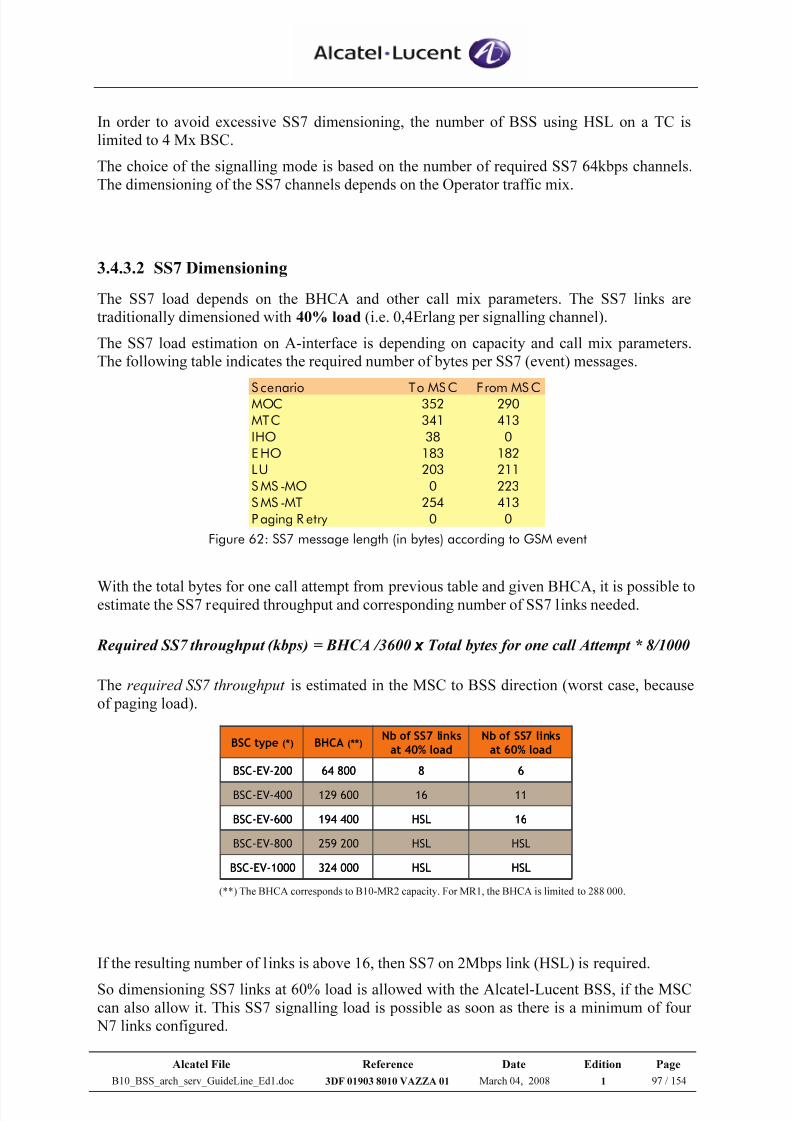
7/21/2019 BSS Architecture Service Guideline B10
http://slidepdf.com/reader/full/bss-architecture-service-guideline-b10 97/154
Alcatel File Reference Date Edition Page
B10_BSS_arch_serv_GuideLine_Ed1.doc 3DF 01903 8010 VAZZA 01 March 04, 2008 1 97 / 154
In order to avoid excessive SS7 dimensioning, the number of BSS using HSL on a TC is
limited to 4 Mx BSC.
The choice of the signalling mode is based on the number of required SS7 64kbps channels.
The dimensioning of the SS7 channels depends on the Operator traffic mix.
3.4.3.2 SS7 Dimensioning
The SS7 load depends on the BHCA and other call mix parameters. The SS7 links are
traditionally dimensioned with 40% load (i.e. 0,4Erlang per signalling channel).
The SS7 load estimation on A-interface is depending on capacity and call mix parameters.
The following table indicates the required number of bytes per SS7 (event) messages.
S cenario To MSC From MS CMOC 352 290
MTC 341 413
IHO 38 0
E HO 183 182
LU 203 211
S MS -MO 0 223
S MS -MT 254 413
P aging R etry 0 0 Figure 62: SS7 message length (in bytes) according to GSM event
With the total bytes for one call attempt from previous table and given BHCA, it is possible toestimate the SS7 required throughput and corresponding number of SS7 links needed.
Required SS7 throughput (kbps) = BHCA /3600 x Total bytes for one call Attempt * 8/1000
The required SS7 throughput is estimated in the MSC to BSS direction (worst case, because
of paging load).
HSLHSL324 000BSC-EV-1000
HSLHSL259 200BSC-EV-800
16HSL194 400BSC-EV-600
1116129 600BSC-EV-400
6864 800BSC-EV-200
Nb of SS7 links
at 60% load
Nb of SS7 links
at 40% loadBHCA (**)BSC type (*)
HSLHSL324 000BSC-EV-1000
HSLHSL259 200BSC-EV-800
16HSL194 400BSC-EV-600
1116129 600BSC-EV-400
6864 800BSC-EV-200
Nb of SS7 links
at 60% load
Nb of SS7 links
at 40% loadBHCA (**)BSC type (*)
(**) The BHCA corresponds to B10-MR2 capacity. For MR1, the BHCA is limited to 288 000.
If the resulting number of links is above 16, then SS7 on 2Mbps link (HSL) is required.
So dimensioning SS7 links at 60% load is allowed with the Alcatel-Lucent BSS, if the MSC
can also allow it. This SS7 signalling load is possible as soon as there is a minimum of four
N7 links configured.
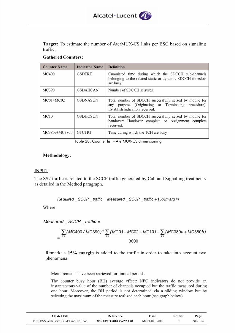
7/21/2019 BSS Architecture Service Guideline B10
http://slidepdf.com/reader/full/bss-architecture-service-guideline-b10 98/154
Alcatel File Reference Date Edition Page
B10_BSS_arch_serv_GuideLine_Ed1.doc 3DF 01903 8010 VAZZA 01 March 04, 2008 1 98 / 154
Target: To estimate the number of AterMUX-CS links per BSC based on signaling
traffic.
Gathered Counters:
Counter Name Indicator Name Definition
MC400 GSDTRT Cumulated time during which the SDCCH sub-channels
belonging to the related static or dynamic SDCCH timeslotsare busy.
MC390 GSDAHCAN Number of SDCCH seizures.
MC01+MC02 GSDNASUN Total number of SDCCH successfully seized by mobile forany purpose (Originating or Terminating procedure):
Establish Indication received.
MC10 GSDHOSUN Total number of SDCCH successfully seized by mobile forhandover: Handover complete or Assignment completereceived.
MC380a+MC380b GTCTRT Time during which the TCH are busy
Table 28: Counter list – AterMUX-CS dimensioning
Methodology:
INPUT
The SS7 traffic is related to the SCCP traffic generated by Call and Signalling treatments
as detailed in the Method paragraph.
inargm%traffic _SCCP _Measured traffic _SCCP _quired Re 15+=
Where:
=traffic _SCCP _Measured
3600
380380100201390400)bMC aMC ( )MC MC MC ( * )MC / MC ( TSTSTS ∑∑∑
++++
=
Remark: a 15% margin is added to the traffic in order to take into account two
phenomena:
Measurements have been retrieved for limited periods
The counter busy hour (BH) average effect: NPO indicators do not provide an
instantaneous value of the number of channels occupied but the traffic measured during
one hour. Moreover, the BH period is not determined via a sliding window but byselecting the maximum of the measure realized each hour (see graph below)
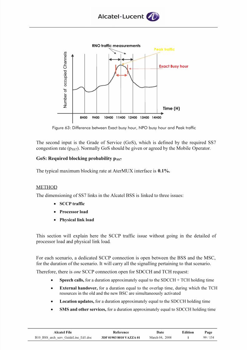
7/21/2019 BSS Architecture Service Guideline B10
http://slidepdf.com/reader/full/bss-architecture-service-guideline-b10 99/154
Alcatel File Reference Date Edition Page
B10_BSS_arch_serv_GuideLine_Ed1.doc 3DF 01903 8010 VAZZA 01 March 04, 2008 1 99 / 154
Time (H) 8H00 9H00 10H00 11H00 12H00 13H00 14H00
RNO traffic measurements
Exact Busy hour
Peak traffic
Figure 63: Difference between Exact busy hour, NPO busy hour and Peak traffic
The second input is the Grade of Service (GoS), which is defined by the required SS7
congestion rate (pSS7). Normally GoS should be given or agreed by the Mobile Operator.
GoS: Required blocking probability pSS7
The typical maximum blocking rate at AterMUX interface is 0.1%.
METHOD
The dimensioning of SS7 links in the Alcatel BSS is linked to three issues:
• SCCP traffic
• Processor load
• Physical link load
This section will explain here the SCCP traffic issue without going in the detailed of
processor load and physical link load.
For each scenario, a dedicated SCCP connection is open between the BSS and the MSC,
for the duration of the scenario. It will carry all the signalling pertaining to that scenario.
Therefore, there is one SCCP connection open for SDCCH and TCH request:
• Speech calls, for a duration approximately equal to the SDCCH + TCH holding time
• External handover, for a duration equal to the overlap time, during which the TCH
resources in the old and the new BSC are simultaneously activated
• Location updates, for a duration approximately equal to the SDCCH holding time
• SMS and other services, for a duration approximately equal to SDCCH holding time
N u m b e r o f o c c u p i e d C h a n
n e l s
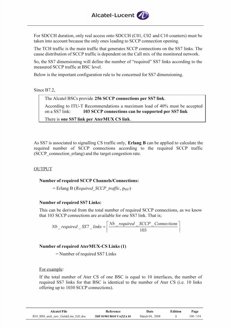
7/21/2019 BSS Architecture Service Guideline B10
http://slidepdf.com/reader/full/bss-architecture-service-guideline-b10 100/154
Alcatel File Reference Date Edition Page
B10_BSS_arch_serv_GuideLine_Ed1.doc 3DF 01903 8010 VAZZA 01 March 04, 2008 1 100 / 154
For SDCCH duration, only real access onto SDCCH (C01, C02 and C10 counters) must be
taken into account because the only ones leading to SCCP connection opening.
The TCH traffic is the main traffic that generates SCCP connections on the SS7 links. The
cause distribution of SCCP traffic is dependent on the Call mix of the monitored network.
So, the SS7 dimensioning will define the number of “required” SS7 links according to the
measured SCCP traffic at BSC level.
Below is the important configuration rule to be concerned for SS7 dimensioning.
Since B7.2,
The Alcatel BSCs provide 256 SCCP connections per SS7 link .
According to ITU-T Recommendations a maximum load of 40% must be accepted
on a SS7 link: 103 SCCP connections can be supported per SS7 link
There is one SS7 link per AterMUX CS link .
As SS7 is associated to signalling CS traffic only, Erlang B can be applied to calculate the
required number of SCCP connections according to the required SCCP traffic
(SCCP_connection_erlang) and the target congestion rate.
OUTPUT
Number of required SCCP Channels/Connections:
= Erlang B ( Required_SCCP_traffic, pSS7)
Number of required SS7 Links:
This can be derived from the total number of required SCCP connections, as we know
that 103 SCCP connections are available for one SS7 link. That is;
=
103
_ _ _ _ 7 _ _
sConnectionSCCP required NblinksSS required Nb
Number of required AterMUX-CS Links (1)
= Number of required SS7 Links
For example:
If the total number of Ater CS of one BSC is equal to 10 interfaces, the number of
required SS7 links for that BSC is identical to the number of Ater CS (i.e. 10 links
offering up to 1030 SCCP connections).
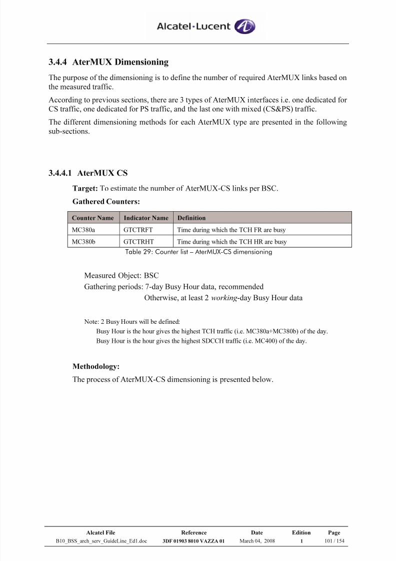
7/21/2019 BSS Architecture Service Guideline B10
http://slidepdf.com/reader/full/bss-architecture-service-guideline-b10 101/154
Alcatel File Reference Date Edition Page
B10_BSS_arch_serv_GuideLine_Ed1.doc 3DF 01903 8010 VAZZA 01 March 04, 2008 1 101 / 154
3.4.4 AterMUX Dimensioning
The purpose of the dimensioning is to define the number of required AterMUX links based on
the measured traffic.
According to previous sections, there are 3 types of AterMUX interfaces i.e. one dedicated forCS traffic, one dedicated for PS traffic, and the last one with mixed (CS&PS) traffic.
The different dimensioning methods for each AterMUX type are presented in the following
sub-sections.
3.4.4.1 AterMUX CS
Target: To estimate the number of AterMUX-CS links per BSC.
Gathered Counters:
Counter Name Indicator Name Definition
MC380a GTCTRFT Time during which the TCH FR are busy
MC380b GTCTRHT Time during which the TCH HR are busy
Table 29: Counter list – AterMUX-CS dimensioning
Measured Object: BSC
Gathering periods: 7-day Busy Hour data, recommended
Otherwise, at least 2 working -day Busy Hour data
Note: 2 Busy Hours will be defined:
Busy Hour is the hour gives the highest TCH traffic (i.e. MC380a+MC380b) of the day.
Busy Hour is the hour gives the highest SDCCH traffic (i.e. MC400) of the day.
Methodology:
The process of AterMUX-CS dimensioning is presented below.
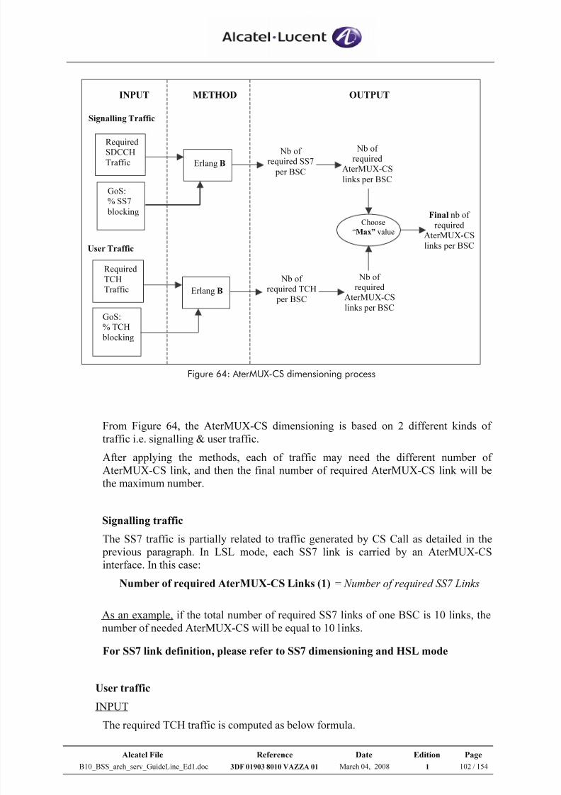
7/21/2019 BSS Architecture Service Guideline B10
http://slidepdf.com/reader/full/bss-architecture-service-guideline-b10 102/154
Alcatel File Reference Date Edition Page
B10_BSS_arch_serv_GuideLine_Ed1.doc 3DF 01903 8010 VAZZA 01 March 04, 2008 1 102 / 154
Erlang B
GoS:% TCH
blocking
Nb of required SS7
per BSC
INPUT OUTPUTMETHOD
Signalling Traffic
User Traffic
RequiredSDCCH
Traffic
Required
TCHTraffic
GoS:% SS7
blocking
Erlang B Nb of
required TCH
per BSC
Nb of required
AterMUX-CS
links per BSC
Nb of required
AterMUX-CS
links per BSC
Choose
“Max” value
Final nb of
requiredAterMUX-CS
links per BSC
Figure 64: AterMUX-CS dimensioning process
From Figure 64, the AterMUX-CS dimensioning is based on 2 different kinds of
traffic i.e. signalling & user traffic.
After applying the methods, each of traffic may need the different number of
AterMUX-CS link, and then the final number of required AterMUX-CS link will be
the maximum number.
Signalling traffic
The SS7 traffic is partially related to traffic generated by CS Call as detailed in the
previous paragraph. In LSL mode, each SS7 link is carried by an AterMUX-CSinterface. In this case:
Number of required AterMUX-CS Links (1) = Number of required SS7 Links
As an example, if the total number of required SS7 links of one BSC is 10 links, the
number of needed AterMUX-CS will be equal to 10 links.
For SS7 link definition, please refer to SS7 dimensioning and HSL mode
User traffic
INPUT
The required TCH traffic is computed as below formula.
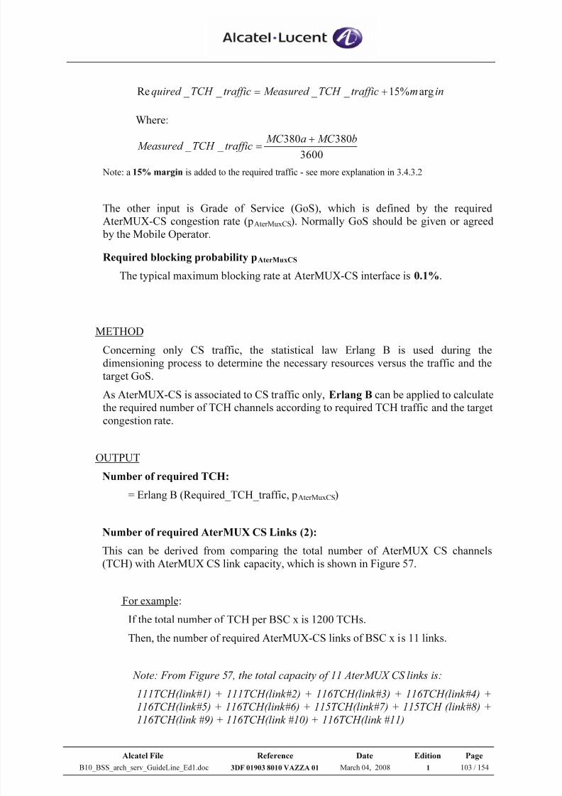
7/21/2019 BSS Architecture Service Guideline B10
http://slidepdf.com/reader/full/bss-architecture-service-guideline-b10 103/154
Alcatel File Reference Date Edition Page
B10_BSS_arch_serv_GuideLine_Ed1.doc 3DF 01903 8010 VAZZA 01 March 04, 2008 1 103 / 154
inmtrafficTCH Measured trafficTCH quired arg%15 _ _ _ _ Re +=
Where:
3600380380 _ _ bMC aMC trafficTCH Measured +
=
Note: a 15% margin is added to the required traffic - see more explanation in 3.4.3.2
The other input is Grade of Service (GoS), which is defined by the required
AterMUX-CS congestion rate (pAterMuxCS). Normally GoS should be given or agreed
by the Mobile Operator.
Required blocking probability pAterMuxCS
The typical maximum blocking rate at AterMUX-CS interface is 0.1%.
METHOD
Concerning only CS traffic, the statistical law Erlang B is used during the
dimensioning process to determine the necessary resources versus the traffic and the
target GoS.
As AterMUX-CS is associated to CS traffic only, Erlang B can be applied to calculate
the required number of TCH channels according to required TCH traffic and the target
congestion rate.
OUTPUT
Number of required TCH:
= Erlang B (Required_TCH_traffic, pAterMuxCS)
Number of required AterMUX CS Links (2):
This can be derived from comparing the total number of AterMUX CS channels
(TCH) with AterMUX CS link capacity, which is shown in Figure 57.
For example:
If the total number of TCH per BSC x is 1200 TCHs.
Then, the number of required AterMUX-CS links of BSC x is 11 links.
Note: From Figure 57, the total capacity of 11 AterMUX CS links is:
111TCH(link#1) + 111TCH(link#2) + 116TCH(link#3) + 116TCH(link#4) +116TCH(link#5) + 116TCH(link#6) + 115TCH(link#7) + 115TCH (link#8) +
116TCH(link #9) + 116TCH(link #10) + 116TCH(link #11)
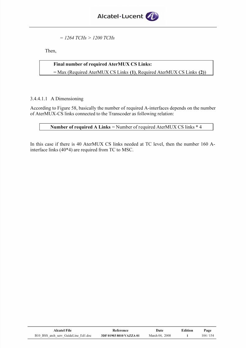
7/21/2019 BSS Architecture Service Guideline B10
http://slidepdf.com/reader/full/bss-architecture-service-guideline-b10 104/154
Alcatel File Reference Date Edition Page
B10_BSS_arch_serv_GuideLine_Ed1.doc 3DF 01903 8010 VAZZA 01 March 04, 2008 1 104 / 154
= 1264 TCHs > 1200 TCHs
Then,
Final number of required AterMUX CS Links:
= Max (Required AterMUX CS Links (1), Required AterMUX CS Links (2))
3.4.4.1.1 A Dimensioning
According to Figure 58, basically the number of required A-interfaces depends on the number
of AterMUX-CS links connected to the Transcoder as following relation:
Number of required A Links = Number of required AterMUX CS links * 4
In this case if there is 40 AterMUX CS links needed at TC level, then the number 160 A-
interface links (40*4) are required from TC to MSC.
7/21/2019 BSS Architecture Service Guideline B10
http://slidepdf.com/reader/full/bss-architecture-service-guideline-b10 105/154
Alcatel File Reference Date Edition Page
B10_BSS_arch_serv_GuideLine_Ed1.doc 3DF 01903 8010 VAZZA 01 March 04, 2008 1 105 / 154
3.4.4.2 AterMUX PS
AterMUX-PS dimensioning is based, like AterMux-CS dimensioning, on 2 different kinds of
traffic i.e. signalling & user traffic. After applying corresponding methods, each of traffic
may need a different number of AterMUX-PS links, and then the final number of requiredAterMUX-PS link will be the maximum number.
The dimensioning methods for Signalling traffic are described in section 3.4.4.2.2
The dimensioning methods for User traffic are described in section 3.6.3
Section 3.4.4.2.1 presents a global view on the AterMux-PS dimensioning process:
1. At which network element level it is applied
2. How the output of dimensioning methods for signalling traffic and for user
traffic are combined together in order to obtain the final recommendation
3.4.4.2.1 Process description
The AterMux-PS dimensioning process must be executed at:
BSC level (doing the hypothesis of a well balanced traffic distribution among the
GP(U) boards connected to the BSC)
AND
GP(U) level (in case of multi-GP(U) configuration and if no additional GP(U)
resource adding found through the method application at BSC level) in order to
handle congestion situations due to unbalanced traffic/cell distribution/mappingon GP(U) boards connected to the BSC. In this case:
A reshuffling operation should be done, before adding GP(U)/AterMUX
resources, if needed, in order to be sure about the congestion root cause
If the reshuffling does not solve the congestion situation, additional
resources, according to the dimensioning method result, should be added
N.B. If, running the dimensioning assessment method, more than 1 GP(U) board are identified as under-dimensioned (i.e. they are not able to handle the required traffic) the adding of GP(U) boards will bedone in an iterative way (1 GP(U) at once) monitoring the consequent impact on the AterMux PS
interface.
In Figure 65 the process for AterMux PS dimensioning that must be applied at BSC level, is
presented:
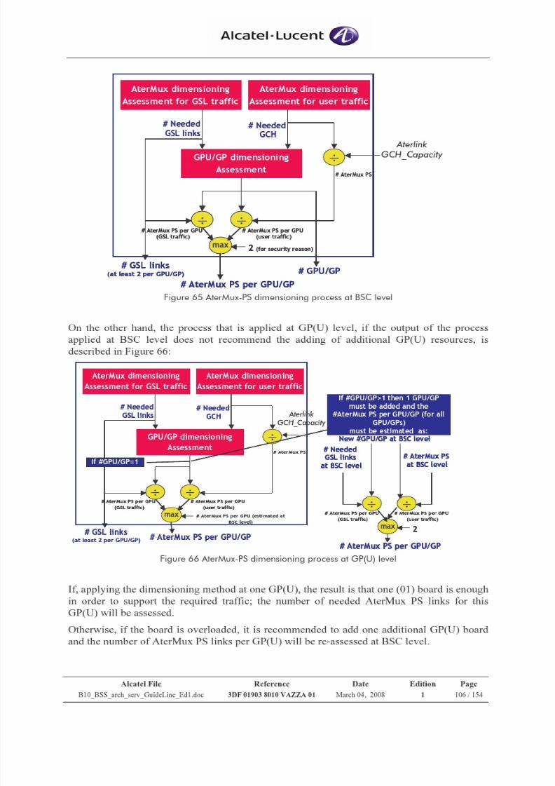
7/21/2019 BSS Architecture Service Guideline B10
http://slidepdf.com/reader/full/bss-architecture-service-guideline-b10 106/154
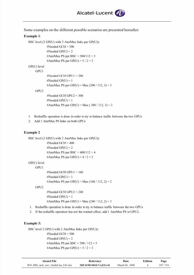
7/21/2019 BSS Architecture Service Guideline B10
http://slidepdf.com/reader/full/bss-architecture-service-guideline-b10 107/154
Alcatel File Reference Date Edition Page
B10_BSS_arch_serv_GuideLine_Ed1.doc 3DF 01903 8010 VAZZA 01 March 04, 2008 1 107 / 154
Some examples on the different possible scenarios are presented hereafter:
Example 1:
BSC level (2 GP(U) with 2 AterMux links per GP(U)):
#Needed GCH = 500#Needed GP(U) = 2
#AterMux PS per BSC = 500/112 = 5
#AterMux PS per GP(U) = 5 / 2 = 3
GP(U) level
GPU1
#Needed GCH GPU1 = 200
#Needed GP(U) = 1
#AterMux PS per GP(U) = Max (200 / 112, 3) = 3
GPU2
#Needed GCH GPU2 = 300#Needed GP(U) = 1
#AterMux PS per GP(U) = Max ( 300 / 112, 3) = 3
1. Reshuffle operation is done in order to try to balance traffic between the two GPUs
2. Add 1 AterMux PS links on both GPUs
Example 2
BSC level (2 GP(U) with 2 AterMux links per GP(U)):
#Needed GCH = 400#Needed GP(U) = 2
#AterMux PS per BSC = 400/112 = 4
#AterMux PS per GP(U) = 4 / 2 = 2
GP(U) level
GPU1
#Needed GCH GPU1 = 160
#Needed GP(U) = 1
#AterMux PS per GP(U) = Max (160 / 112, 2) = 2
GPU2
#Needed GCH GPU2 = 240#Needed GP(U) = 1
#AterMux PS per GP(U) = Max (240 / 112, 2) = 3
1. Reshuffle operation is done in order to try to balance traffic between the two GPUs
2. If the reshuffle operation has not the wanted effect, add 1 AterMux PS to GPU2.
Example 3:
BSC level 2 GP(U) with 2 AterMux links per GP(U)):
#Needed GCH = 500
#Needed GP(U) = 2
#AterMux PS per BSC = 500 / 112 = 5
#AterMux PS per GP(U) = 5 / 2 = 3
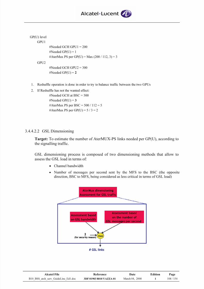
7/21/2019 BSS Architecture Service Guideline B10
http://slidepdf.com/reader/full/bss-architecture-service-guideline-b10 108/154
Alcatel File Reference Date Edition Page
B10_BSS_arch_serv_GuideLine_Ed1.doc 3DF 01903 8010 VAZZA 01 March 04, 2008 1 108 / 154
GP(U) level
GPU1
#Needed GCH GPU1 = 200
#Needed GP(U) = 1
#AterMux PS per GP(U) = Max (200 / 112, 3) = 3
GPU2
#Needed GCH GPU2 = 300
#Needed GP(U) = 2
1. Reshuffle operation is done in order to try to balance traffic between the two GPUs
2. If Reshuffle has not the wanted effect:
#Needed GCH at BSC = 500
#Needed GP(U) = 3#AterMux PS per BSC = 500 / 112 = 5
#AterMux PS per GP(U) = 5 / 3 = 2
3.4.4.2.2 GSL Dimensioning
Target: To estimate the number of AterMUX-PS links needed per GP(U), according to
the signalling traffic.
GSL dimensioning process is composed of two dimensioning methods that allow to
assess the GSL load in terms of:
• Channel bandwidth
• Number of messages per second sent by the MFS to the BSC (the opposite
direction, BSC to MFS, being considered as less critical in terms of GSL load)
AterMux dimensioning
Assessment for GSL traffic
Assessment based
on GSL bandwidth
Assessment based
on the number of
GSL messages per second
max2
(for security reason)
# GSL links
AterMux dimensioning
Assessment for GSL traffic
Assessment based
on GSL bandwidth
Assessment based
on the number of
GSL messages per second
max2
(for security reason)
# GSL links
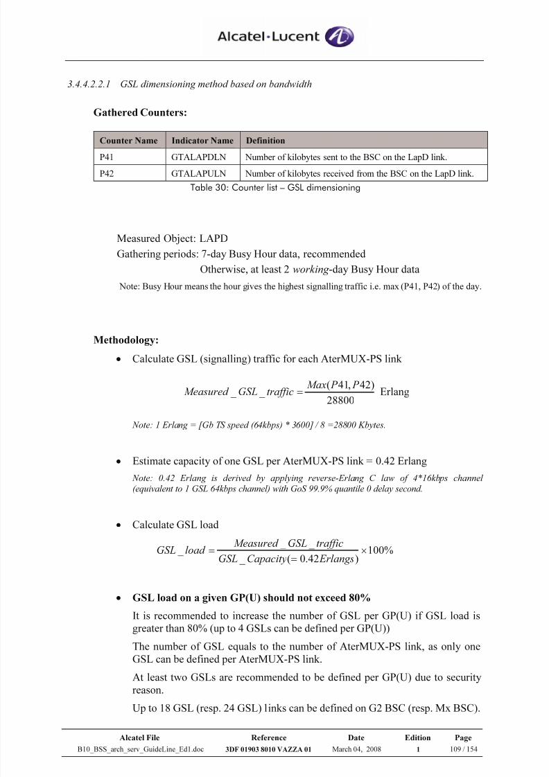
7/21/2019 BSS Architecture Service Guideline B10
http://slidepdf.com/reader/full/bss-architecture-service-guideline-b10 109/154
Alcatel File Reference Date Edition Page
B10_BSS_arch_serv_GuideLine_Ed1.doc 3DF 01903 8010 VAZZA 01 March 04, 2008 1 109 / 154
3.4.4.2.2.1 GSL dimensioning method based on bandwidth
Gathered Counters:
Counter Name Indicator Name Definition
P41 GTALAPDLN Number of kilobytes sent to the BSC on the LapD link.
P42 GTALAPULN Number of kilobytes received from the BSC on the LapD link.
Table 30: Counter list – GSL dimensioning
Measured Object: LAPD
Gathering periods: 7-day Busy Hour data, recommended
Otherwise, at least 2 working -day Busy Hour data Note: Busy Hour means the hour gives the highest signalling traffic i.e. max (P41, P42) of the day.
Methodology:
• Calculate GSL (signalling) traffic for each AterMUX-PS link
28800
)42,41( _ _
P P MaxtrafficGSLMeasured = Erlang
Note: 1 Erlang = [Gb TS speed (64kbps) * 3600] / 8 =28800 Kbytes.
• Estimate capacity of one GSL per AterMUX-PS link = 0.42 Erlang
Note: 0.42 Erlang is derived by applying reverse-Erlang C law of 4*16kbps channel
(equivalent to 1 GSL 64kbps channel) with GoS 99.9% quantile 0 delay second.
• Calculate GSL load
%100)42.0( _
_ _ _ ×
=
=
ErlangsCapacityGSLtrafficGSLMeasured load GSL
• GSL load on a given GP(U) should not exceed 80%
It is recommended to increase the number of GSL per GP(U) if GSL load is
greater than 80% (up to 4 GSLs can be defined per GP(U))
The number of GSL equals to the number of AterMUX-PS link, as only one
GSL can be defined per AterMUX-PS link.
At least two GSLs are recommended to be defined per GP(U) due to securityreason.
Up to 18 GSL (resp. 24 GSL) links can be defined on G2 BSC (resp. Mx BSC).
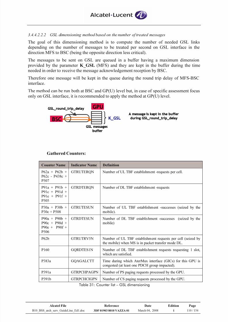
7/21/2019 BSS Architecture Service Guideline B10
http://slidepdf.com/reader/full/bss-architecture-service-guideline-b10 110/154
Alcatel File Reference Date Edition Page
B10_BSS_arch_serv_GuideLine_Ed1.doc 3DF 01903 8010 VAZZA 01 March 04, 2008 1 110 / 154
3.4.4.2.2.2 GSL dimensioning method based on the number of treated messages
The goal of this dimensioning method is to compute the number of needed GSL links
depending on the number of messages to be treated per second on GSL interface in the
direction MFS to BSC (being the opposite direction less critical).
The messages to be sent on GSL are queued in a buffer having a maximum dimension
provided by the parameter K_GSL (MFS) and they are kept in the buffer during the time
needed in order to receive the message acknowledgement reception by BSC.
Therefore one message will be kept in the queue during the round trip delay of MFS-BSC
interface.
The method can be run both at BSC and GP(U) level but, in case of specific assessment focus
only on GSL interface, it is recommended to apply the method at GP(U) level.
BSC
GPU
K_GSL
GSL messages
buffer
GSL_round_trip_delay
A message is kept in the bufferduring GSL_round_trip_delayBSC
GPU
K_GSL
GSL messages
buffer
GSL_round_trip_delay
A message is kept in the bufferduring GSL_round_trip_delayBSC
GPU
K_GSL
GSL messages
buffer
GSL_round_trip_delay
A message is kept in the bufferduring GSL_round_trip_delay
Gathered Counters:
Counter Name Indicator Name Definition
P62a + P62b +P62c - P438c +P507
GTRUTERQN Number of UL TBF establishment -requests per cell.
P91a + P91b +
P91c + P91d +P91e + P91f +P505
GTRDTERQN Number of DL TBF establishment -requests
P30a + P30b +
P30c + P508
GTRUTESUN Number of UL TBF establishment -successes (seized by the
mobile).
P90a + P90b +P90c + P90d +P90e + P90f +
P506
GTRDTESUN Number of DL TBF establishment -successes (seized by themobile)
P62b GTRUTRV5N Number of UL TBF establishment requests per cell (seized bythe mobile) when MS is in packet transfer mode DL.
P160 GQRDTES1N Number of DL TBF establishment requests requesting 1 slot,which are satisfied.
P383a GQAGALCTT Time during which AterMux interface (GICs) for this GPU iscongested (at least one PDCH group impacted).
P391a GTRPCHPAGPN Number of PS paging requests processed by the GPU.
P391b GTRPCHCIGPN Number of CS paging requests processed by the GPU.
Table 31: Counter list – GSL dimensioning
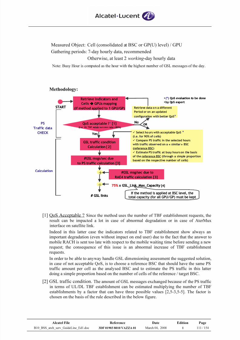
7/21/2019 BSS Architecture Service Guideline B10
http://slidepdf.com/reader/full/bss-architecture-service-guideline-b10 111/154
Alcatel File Reference Date Edition Page
B10_BSS_arch_serv_GuideLine_Ed1.doc 3DF 01903 8010 VAZZA 01 March 04, 2008 1 111 / 154
Measured Object: Cell (consolidated at BSC or GP(U) level) / GPU
Gathering periods: 7-day hourly data, recommended
Otherwise, at least 2 working -day hourly data Note: Busy Hour is computed as the hour with the highest number of GSL messages of the day.
Methodology:
Retrieve indicators and
Cells GPUs mapping
(if method applied to 1 GPU/GP)
GSL traffic condition
Calculation [2]
# GSL links
#GSL msg/sec due to
RAE4 traffic calculation [3]
#GSL msgs/sec due
to PS traffic calculation [3]
•(*) QoS evaluation to be done
•by QoS expert
÷ 75% x GSL_Link_Max_Capacity [4]
+
QoS acceptable ?* [1](i.e. UL TBF estab success rate >80%)
Yes
Retrieve data on a different
Period or on an updated
configuration with better QoS*
Select hours with acceptable QoS *(i.e. for 90% of cells)
Compare PS traffic in the selected hours
with traffic observed on a « similar » BSC
(reference BSC)
Estimate PS traffic at busy hourson the basis
of the reference BSC (through a simple proportion
based on the respective number of cells)
NoOR
START
PS
Traffic data
CHECK
Calculation
If the method is applied at BSC level, thetotal capacity (for all GPU/GP) must be kept
[1] QoS Acceptable ? Since the method uses the number of TBF establishment requests, the
result can be impacted a lot in case of abnormal degradation or in case of AterMux
interface on satellite link.
Indeed in this latter case the indicators related to TBF establishment show always an
important degradation (even without impact on end user) due to the fact that the answer tomobile RACH is sent too late with respect to the mobile waiting time before sending a new
request; the consequence of this issue is an abnormal increase of TBF establishment
requests.
In order to be able to anyway handle GSL dimensioning assessment the suggested solution,
in case of not acceptable QoS, is to choose a reference BSC that should have the same PS
traffic amount per cell as the analysed BSC and to estimate the PS traffic in this latter
doing a simple proportion based on the number of cells of the reference / target BSC.
[2] GSL traffic condition. The amount of GSL messages exchanged because of the PS traffic
in terms of UL/DL TBF establishment can be estimated multiplying the number of TBF
establishments by a factor that can have three possible values [2,5-3,5-5]. The factor is
chosen on the basis of the rule described in the below figure.
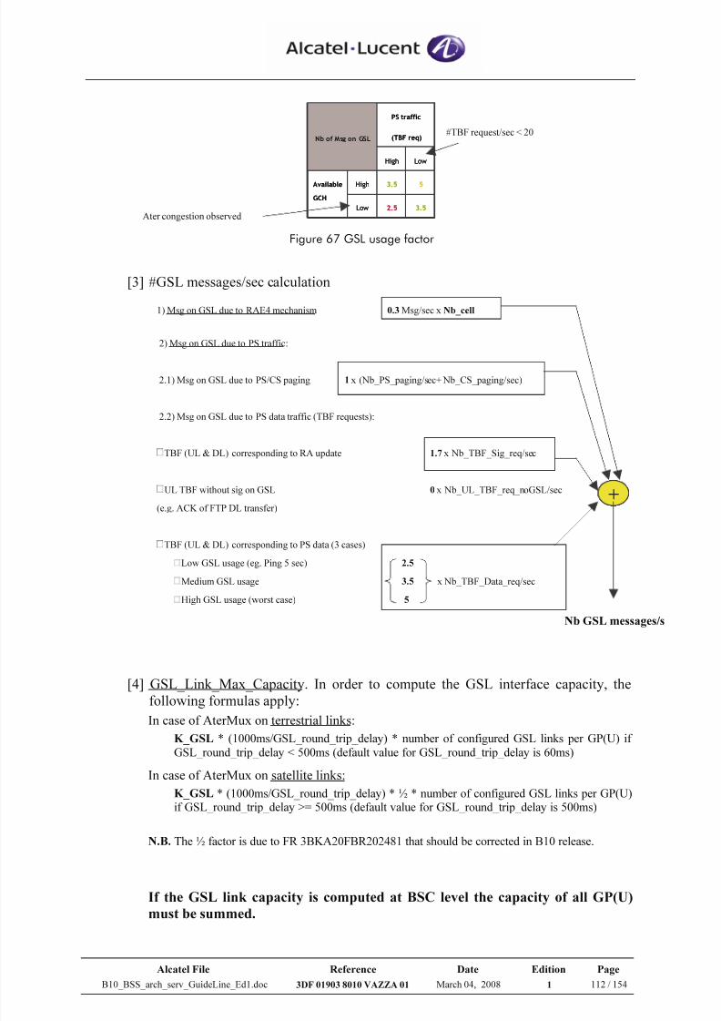
7/21/2019 BSS Architecture Service Guideline B10
http://slidepdf.com/reader/full/bss-architecture-service-guideline-b10 112/154
Alcatel File Reference Date Edition Page
B10_BSS_arch_serv_GuideLine_Ed1.doc 3DF 01903 8010 VAZZA 01 March 04, 2008 1 112 / 154
3.52.5Low
53.5HighAvailable
GCH
LowHigh
PS traffic
(TBF req)Nb of Msg on GSL
3.52.5Low
53.5HighAvailable
GCH
LowHigh
PS traffic
(TBF req)Nb of Msg on GSL
Ater congestion observed
#TBF request/sec < 20
Figure 67 GSL usage factor
[3] #GSL messages/sec calculation
1) Msg on GSL due to RAE4 mechanism 0.3 Msg/sec x Nb_cell
2) Msg on GSL due to PS traffic:
2.1) Msg on GSL due to PS/CS paging 1 x (Nb_PS_paging/sec+ Nb_CS_paging/sec)
2.2) Msg on GSL due to PS data traffic (TBF requests):
TBF (UL & DL) corresponding to RA update 1.7 x Nb_TBF_Sig_req/sec
UL TBF without sig on GSL 0 x Nb_UL_TBF_req_noGSL/sec
(e.g. ACK of FTP DL transfer)
TBF (UL & DL) corresponding to PS data (3 cases)
Low GSL usage (eg. Ping 5 sec) 2.5
Medium GSL usage 3.5 x Nb_TBF_Data_req/sec
High GSL usage (worst case) 5
[4] GSL_Link_Max_Capacity. In order to compute the GSL interface capacity, the
following formulas apply:
In case of AterMux on terrestrial links:
K_GSL * (1000ms/GSL_round_trip_delay) * number of configured GSL links per GP(U) if
GSL_round_trip_delay < 500ms (default value for GSL_round_trip_delay is 60ms)
In case of AterMux on satellite links:
K_GSL * (1000ms/GSL_round_trip_delay) * ½ * number of configured GSL links per GP(U)if GSL_round_trip_delay >= 500ms (default value for GSL_round_trip_delay is 500ms)
N.B. The ½ factor is due to FR 3BKA20FBR202481 that should be corrected in B10 release.
If the GSL link capacity is computed at BSC level the capacity of all GP(U)must be summed.
++
Nb GSL messages/s
7/21/2019 BSS Architecture Service Guideline B10
http://slidepdf.com/reader/full/bss-architecture-service-guideline-b10 113/154
Alcatel File Reference Date Edition Page
B10_BSS_arch_serv_GuideLine_Ed1.doc 3DF 01903 8010 VAZZA 01 March 04, 2008 1 113 / 154
• Calculate GSL load (in terms of treated messages)
The computation of Nb_GSL_messages_per_sec and GSL_Link_Max_Capacity is
detailed in the previous “Methodology” description.
%100 _ _ _
sec _ _ _ _ ×=
CapacityMax Link GSL
per messagesGSL Nbload GSL
• GSL load in terms of treated messages per second on a given GP(U) should not
exceed 75%
It is recommended to increase the number of GSL per GP(U) if GSL load is greater
than 75%.
3.4.4.2.3 GCH/AterMUX-PS Dimensioning
Target: To estimate the number of AterMUX-PS links needed per GP(U),
according to user traffic.
The main principle is to have roughly same number of AterMUX-PS links per
GP(U) (at least 2 links per GP(U)) for all the GP(U) connected to the same BSC.
N.B. This will not assure a balanced load distribution among the GP(U) boards connected
to the BSC, because the AterMux interface capacity is not directly taken into account in the
cell distribution criteria in MFS.
For more details on cell mapping on GP(U) boards, please refer to [15].
In order to estimate the number of AterMux-PS links per GP(U), analyzing the
whole BSC, two main data must be estimated:
• Number of required GCH per BSC
• Number of required GP(U) per BSC
Please find details on the method allowing to estimate the number of GCH (per
BSC or per GPU) in the section 3.6.3.1 and 3.6.3.2.
Please find details of GP(U) dimensioning in the section 3.6.3
Having the number of required GCH and the number of GP(U) board, the Number
of AterMUX-PS links per BSC
= Number of required GCH per BSC / 112 GCH
Remark: 112 GCH is generally applied in case of with GSL configuration, otherwise 116 GCH may
be applied as well. See details in Figure 59 and also refer to section 3.4.4.2.2 GSL dimensioning.
Number of AterMUX-PS links per GP(U) (based on user traffic) =
Number of AterMUX-PS links per BSC / Number of required GP(U) per BSC
7/21/2019 BSS Architecture Service Guideline B10
http://slidepdf.com/reader/full/bss-architecture-service-guideline-b10 114/154
Alcatel File Reference Date Edition Page
B10_BSS_arch_serv_GuideLine_Ed1.doc 3DF 01903 8010 VAZZA 01 March 04, 2008 1 114 / 154
Finally,
Number of AterMUX-PS links per GP(U) (based on signalling + user traffic) =
Max (Number of required GSL per GP(U), Number of AterMUX-PS links per GP(U)
based on user traffic, 2)
Remark: it is highly recommended to have at least 2 AterMUX-PS links per GP(U) due to securityreason.
Example:
If Number of required GCH per BSC = 330
Number of required GP(U) per BSC = 2
Number of required GSL per GP(U) = 2
How many AterMUX-PS links per GP(U) are required?
- Determine Number of AterMUX-PS links per GP(U) based on user traffic
Number of AterMUX-PS links per BSC = 330/112 = 3 links
Number of AterMUX-PS links per GP(U) = 3 / 2 = 2 links
- Determine Number of AterMUX-PS links per GP(U) based on signalling + user traffic
= Max (Number of required GSL per GP(U), Number of AterMUX-PS links per
GP(U) based on user traffic, 2)
= Max (2, 2, 2)
= 2 links
Assessment:
AterMUX-PS re-dimensioning is required when:
GSL load in terms of bandwidth is exceeding 80%.
GSL load in terms of number of treated messages per second is exceeding 75%.
GP(U) Ater time congestion rate exceeding 0.1 % can be observed regularly.
GP(U) re-dimensioning is performed.
Warning:
It could happen that, because of unbalanced traffic distribution among the GP(U)
boards connected to one BSC, one GP(U) board is more loaded than others.
This can be discovered applying the AterMux-PS dimensioning process at GP(U)
level. Some examples are provided in 3.4.4.2.1.
7/21/2019 BSS Architecture Service Guideline B10
http://slidepdf.com/reader/full/bss-architecture-service-guideline-b10 115/154
Alcatel File Reference Date Edition Page
B10_BSS_arch_serv_GuideLine_Ed1.doc 3DF 01903 8010 VAZZA 01 March 04, 2008 1 115 / 154
3.4.4.3 AterMUX CS/PS
Target: To estimate the number of AterMUX-CS/PS links needed per BSC (or
GP(U)).
GP(U) & AterMUX-CS dimensioning are pre-requisite to be performed in order to
provide input data for AterMUX-PS dimensioning.
Please find details of GP(U) dimensioning in the section 3.6.3
Please find details of AterMUX-CS dimensioning in the section 3.4.4.1
The input data for AterMUX-CS/PS dimensioning are:
Number of required TCH per BSC taken from AterMUX-CS dimensioning
Number of required GCH per BSC taken from GP(U) dimensioning
Example of AterMUX-CS/PS dimensioning:
If Number of required TCH per BSC = 250 TCHs
Number of required GCH per BSC = 50 GCHs
Then
From 250 TCH, 222 TCHs can be fit into 2 AterMUX-CS links
Note: From Figure 57, the total capacity of AterMUX-CS links is:
111TCH(link#1) + 111TCH(link#2) = 222 TCHs
So, 250 –222 = 28 TCHs are remaining
But 28 remaining TCHs and 50 GCHs can be fit into 1 AterMUX-CS/PS links
with 50% sharing, see Table 27
Therefore, based on this example, we need 2 AterMUX-CS links and 1 AterMUX-
CS/PS links.
Remark: the minimum usage of mixed AterMUX CS/PS is recommended.
Assessment:
AterMUX-CS/PS re-dimensioning is required when:
The increase of TCH traffic
GP(U) Ater time congestion rate exceeding 0.1 % can be observed regularly.
GP(U) re-dimensioning is performed.
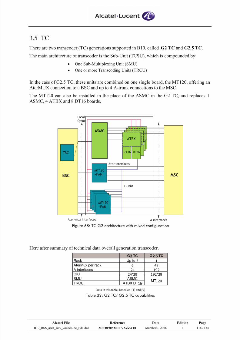
7/21/2019 BSS Architecture Service Guideline B10
http://slidepdf.com/reader/full/bss-architecture-service-guideline-b10 116/154
Alcatel File Reference Date Edition Page
B10_BSS_arch_serv_GuideLine_Ed1.doc 3DF 01903 8010 VAZZA 01 March 04, 2008 1 116 / 154
3.5 TC
There are two transcoder (TC) generations supported in B10, called G2 TC and G2.5 TC.
The main architecture of transcoder is the Sub-Unit (TCSU), which is compounded by:
• One Sub-Multiplexing Unit (SMU)
• One or more Transcoding Units (TRCU)
In the case of G2.5 TC, these units are combined on one single board, the MT120, offering an
AterMUX connection to a BSC and up to 4 A-trunk connections to the MSC.
The MT120 can also be installed in the place of the ASMC in the G2 TC, and replaces 1
ASMC, 4 ATBX and 8 DT16 boards.
BSC
ASMCASMC
ASMC
or
MT120
MT120
+FAN
ATBX
DT16 DT16TSC
Ater-mux interfaces
MT120
+FAN
Ater interfaces
A interfaces
Local
Qmux
TC bus
MSC
Figure 68: TC G2 architecture with mixed configuration
Here after summary of technical data overall generation transcoder.
G2 TC G2.5 TC
Rack Up to 3 1
AterMux per rack 6 48
A interfaces 24 192
CIC 24*29 192*29
SMU ASMC
TRCU ATBX DT16MT120
Data in this table, based on [1] and [9]
Table 32: G2 TC/ G2.5 TC capabilities
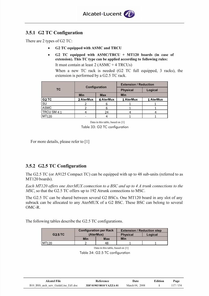
7/21/2019 BSS Architecture Service Guideline B10
http://slidepdf.com/reader/full/bss-architecture-service-guideline-b10 117/154
Alcatel File Reference Date Edition Page
B10_BSS_arch_serv_GuideLine_Ed1.doc 3DF 01903 8010 VAZZA 01 March 04, 2008 1 117 / 154
3.5.1 G2 TC Configuration
There are 2 types of G2 TC:
• G2 TC equipped with ASMC and TRCU
• G2 TC equipped with ASMC/TRCU + MT120 boards (in case of
extension). This TC type can be applied according to following rules:
It must contain at least 2 (ASMC + 4 TRCUs)
When a new TC rack is needed (G2 TC full equipped, 3 racks), the
extension is performed by a G2.5 TC rack.
Extension / Reduction
Physical Logical
Min Max
G2 TC 2AterMux 6AterMux 1AterMux 1AterMux
SU 2 6 1 1 ASMC 2 6 1 1
TRCU SM 4:1 4 24 4 4
MT120 - 4 1 1
TCConfiguration
Min
Data in this table, based on [1]
Table 33: G2 TC configuration
For more details, please refer to [1]
3.5.2 G2.5 TC Configuration
The G2.5 TC (or A9125 Compact TC) can be equipped with up to 48 sub-units (referred to as
MT120 boards).
Each MT120 offers one AterMUX connection to a BSC and up to 4 A trunk connections to the
MSC , so that the G2.5 TC offers up to 192 Atrunk connections to MSC.
The G2.5 TC can be shared between several G2 BSCs. One MT120 board in any slot of any
subrack can be allocated to any AterMUX of a G2 BSC. These BSC can belong to several
OMC-R.
The following tables describe the G2.5 TC configurations.
Extension / Reduction step
Physical Logical
Min Max
MT120 2 48 1 1
G2.5 TC
Configuration per Rack
(AterMux)
Min
Data in this table, based on [1]
Table 34: G2.5 TC configuration
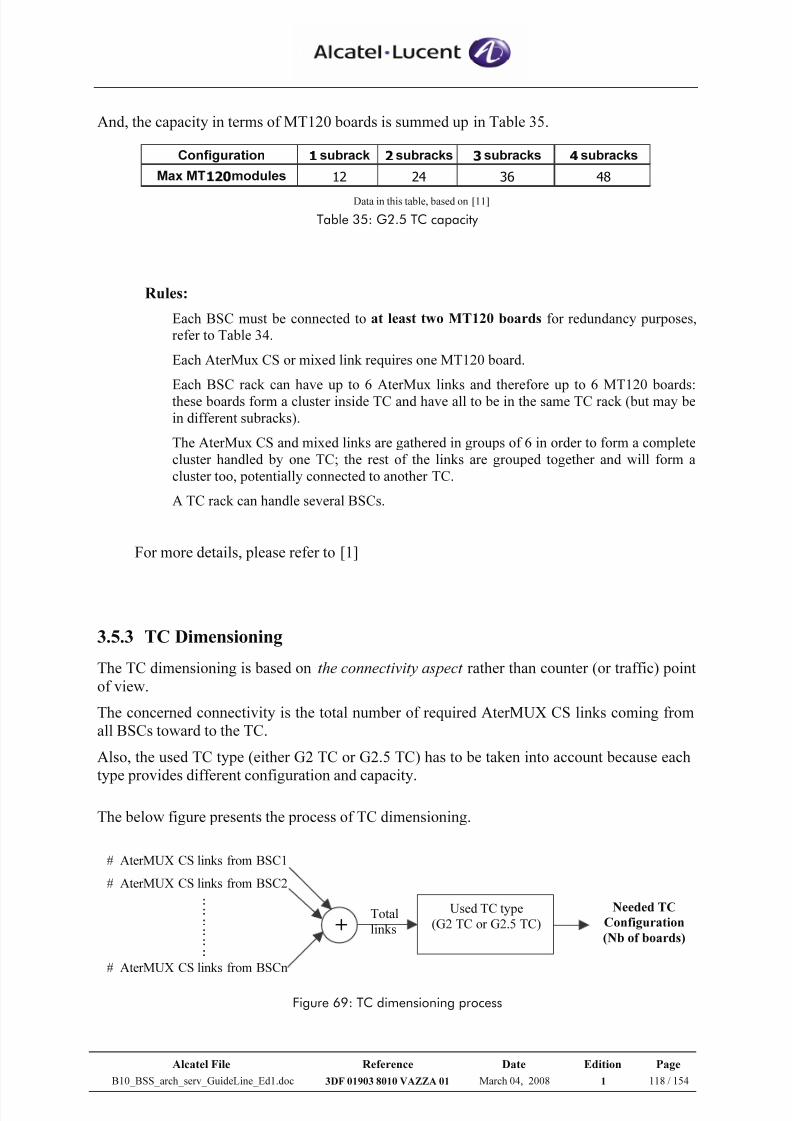
7/21/2019 BSS Architecture Service Guideline B10
http://slidepdf.com/reader/full/bss-architecture-service-guideline-b10 118/154
Alcatel File Reference Date Edition Page
B10_BSS_arch_serv_GuideLine_Ed1.doc 3DF 01903 8010 VAZZA 01 March 04, 2008 1 118 / 154
And, the capacity in terms of MT120 boards is summed up in Table 35.
Configuration 1 subrack 2 subracks 3 subracks 4 subracks
Max MT120modules 12 24 36 48 Data in this table, based on [11]
Table 35: G2.5 TC capacity
Rules:
Each BSC must be connected to at least two MT120 boards for redundancy purposes,
refer to Table 34.
Each AterMux CS or mixed link requires one MT120 board.
Each BSC rack can have up to 6 AterMux links and therefore up to 6 MT120 boards:
these boards form a cluster inside TC and have all to be in the same TC rack (but may be
in different subracks).
The AterMux CS and mixed links are gathered in groups of 6 in order to form a complete
cluster handled by one TC; the rest of the links are grouped together and will form a
cluster too, potentially connected to another TC.
A TC rack can handle several BSCs.
For more details, please refer to [1]
3.5.3 TC Dimensioning
The TC dimensioning is based on the connectivity aspect rather than counter (or traffic) point
of view.
The concerned connectivity is the total number of required AterMUX CS links coming from
all BSCs toward to the TC.
Also, the used TC type (either G2 TC or G2.5 TC) has to be taken into account because each
type provides different configuration and capacity.
The below figure presents the process of TC dimensioning.
# AterMUX CS links from BSC1
# AterMUX CS links from BSC2
# AterMUX CS links from BSCn
Used TC type
(G2 TC or G2.5 TC)Total
links
Needed TC
Configuration
(Nb of boards)
:
:
:
:
:
:
+
Figure 69: TC dimensioning process
7/21/2019 BSS Architecture Service Guideline B10
http://slidepdf.com/reader/full/bss-architecture-service-guideline-b10 119/154
Alcatel File Reference Date Edition Page
B10_BSS_arch_serv_GuideLine_Ed1.doc 3DF 01903 8010 VAZZA 01 March 04, 2008 1 119 / 154
For example;
If a small network consists of 4 BSCs with following required AterMUX CS links;
BSCa: 10 AterMUX CS links
BSCb: 12 AterMUX CS links
BSCc: 6 AterMUX CS links
BSCd: 8 AterMUX CS links
and the chosen TC type is G2.5 TC.
Then refer to section 3.5.2; we know that each AterMUX link needs one MT120 board
of G2.5 TC .
Therefore,
BSCa needs 10 MT120 boards
BSCb needs 12 MT120 boards
BSCc needs 6 MT120 boards
BSCd needs 8 MT120 boards
As 36 MT120 boards are needed, this required one G2.5 TC with 3 subracks –
refer to Table 35.
Total = 36 MT 120 boards
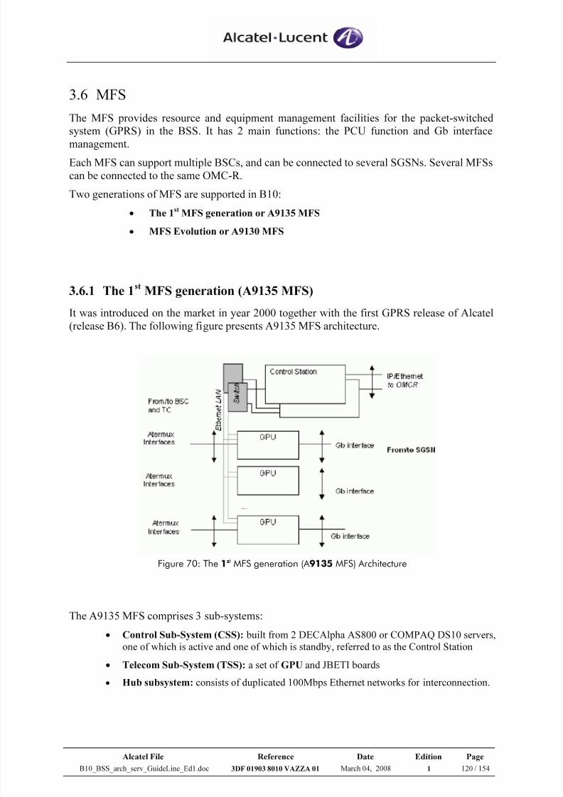
7/21/2019 BSS Architecture Service Guideline B10
http://slidepdf.com/reader/full/bss-architecture-service-guideline-b10 120/154
Alcatel File Reference Date Edition Page
B10_BSS_arch_serv_GuideLine_Ed1.doc 3DF 01903 8010 VAZZA 01 March 04, 2008 1 120 / 154
3.6 MFS
The MFS provides resource and equipment management facilities for the packet-switched
system (GPRS) in the BSS. It has 2 main functions: the PCU function and Gb interface
management.
Each MFS can support multiple BSCs, and can be connected to several SGSNs. Several MFSs
can be connected to the same OMC-R.
Two generations of MFS are supported in B10:
• The 1st
MFS generation or A9135 MFS
• MFS Evolution or A9130 MFS
3.6.1 The 1st
MFS generation (A9135 MFS)
It was introduced on the market in year 2000 together with the first GPRS release of Alcatel
(release B6). The following figure presents A9135 MFS architecture.
Figure 70: The 1st MFS generation (A 9135 MFS) Architecture
The A9135 MFS comprises 3 sub-systems:
• Control Sub-System (CSS): built from 2 DECAlpha AS800 or COMPAQ DS10 servers,
one of which is active and one of which is standby, referred to as the Control Station
• Telecom Sub-System (TSS): a set of GPU and JBETI boards
• Hub subsystem: consists of duplicated 100Mbps Ethernet networks for interconnection.
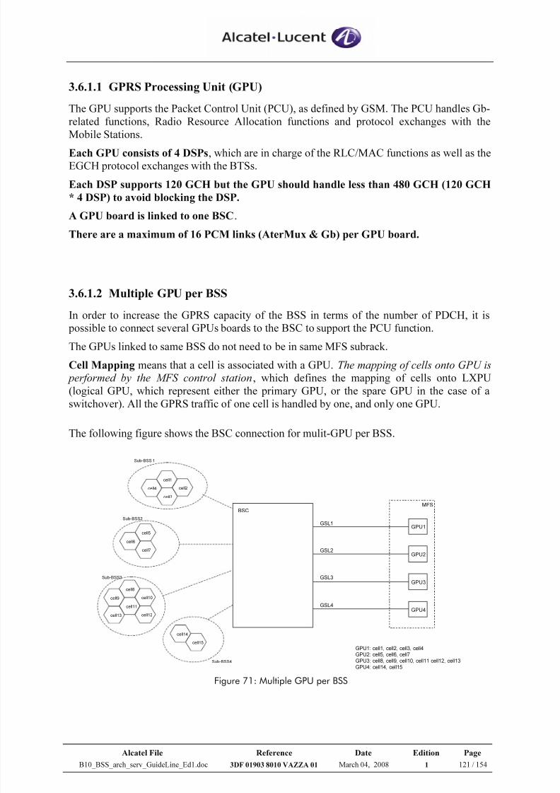
7/21/2019 BSS Architecture Service Guideline B10
http://slidepdf.com/reader/full/bss-architecture-service-guideline-b10 121/154
Alcatel File Reference Date Edition Page
B10_BSS_arch_serv_GuideLine_Ed1.doc 3DF 01903 8010 VAZZA 01 March 04, 2008 1 121 / 154
3.6.1.1 GPRS Processing Unit (GPU)
The GPU supports the Packet Control Unit (PCU), as defined by GSM. The PCU handles Gb-
related functions, Radio Resource Allocation functions and protocol exchanges with the
Mobile Stations.Each GPU consists of 4 DSPs, which are in charge of the RLC/MAC functions as well as the
EGCH protocol exchanges with the BTSs.
Each DSP supports 120 GCH but the GPU should handle less than 480 GCH (120 GCH
* 4 DSP) to avoid blocking the DSP.
A GPU board is linked to one BSC.
There are a maximum of 16 PCM links (AterMux & Gb) per GPU board.
3.6.1.2 Multiple GPU per BSS
In order to increase the GPRS capacity of the BSS in terms of the number of PDCH, it is
possible to connect several GPUs boards to the BSC to support the PCU function.
The GPUs linked to same BSS do not need to be in same MFS subrack.
Cell Mapping means that a cell is associated with a GPU. The mapping of cells onto GPU is
performed by the MFS control station, which defines the mapping of cells onto LXPU
(logical GPU, which represent either the primary GPU, or the spare GPU in the case of a
switchover). All the GPRS traffic of one cell is handled by one, and only one GPU.
The following figure shows the BSC connection for mulit-GPU per BSS.
BSC
GPU1
GPU2
GPU3
GPU4
MFS
GSL1
GSL2
cell15
cell14
cell1
cell2
cell3
cell4
Sub-BSS 1
cell5
cell7
cell6
Sub-BSS2
Sub-BSS4
cell8
cell10
cell11
cell9
cell12cell13
Sub-BSS3 GSL3
GSL4
GPU1: cell1, cell2, cell3, cell4
GPU2: cell5, cell6, cell7
GPU3: cell8, cell9, cell10, cell11 cell12, cell13
GPU4: cell14, cell15 Figure 71: Multiple GPU per BSS
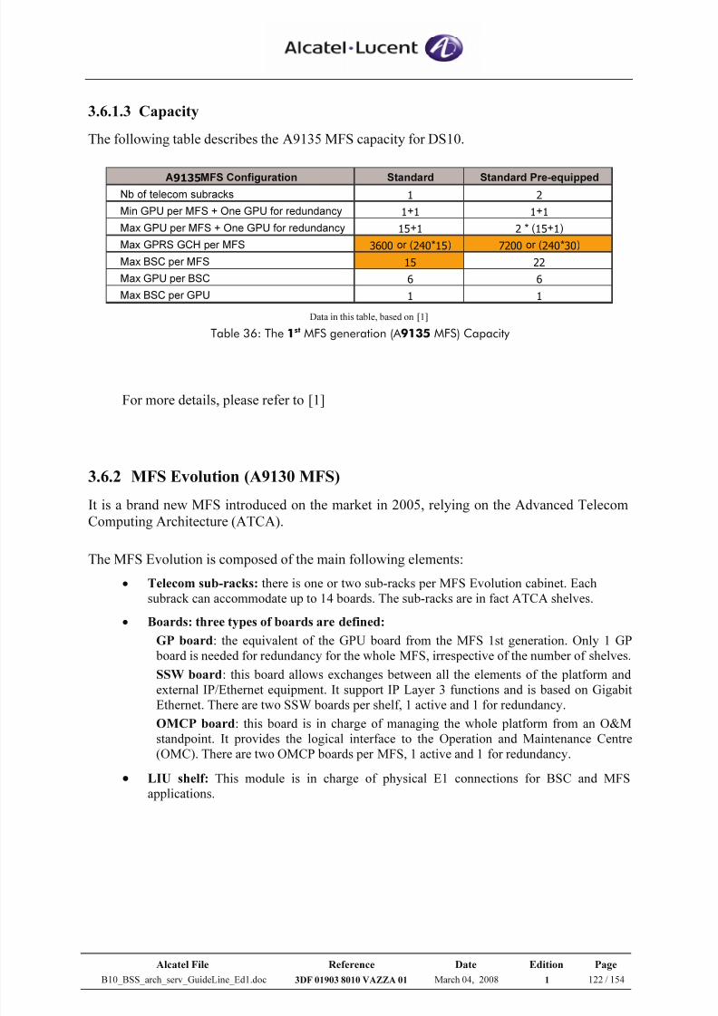
7/21/2019 BSS Architecture Service Guideline B10
http://slidepdf.com/reader/full/bss-architecture-service-guideline-b10 122/154
Alcatel File Reference Date Edition Page
B10_BSS_arch_serv_GuideLine_Ed1.doc 3DF 01903 8010 VAZZA 01 March 04, 2008 1 122 / 154
3.6.1.3 Capacity
The following table describes the A9135 MFS capacity for DS10.
A9135MFS Configuration Standard Standard Pre-equippedNb of telecom subracks 1 2
Min GPU per MFS + One GPU for redundancy 1+1 1+1
Max GPU per MFS + One GPU for redundancy 15+1 2 * (15+1)
Max GPRS GCH per MFS 3600 or (240*15) 7200 or (240*30)
Max BSC per MFS 15 22
Max GPU per BSC 6 6
Max BSC per GPU 1 1
Data in this table, based on [1]
Table 36: The 1st MFS generation (A 9135 MFS) Capacity
For more details, please refer to [1]
3.6.2 MFS Evolution (A9130 MFS)
It is a brand new MFS introduced on the market in 2005, relying on the Advanced Telecom
Computing Architecture (ATCA).
The MFS Evolution is composed of the main following elements:
• Telecom sub-racks: there is one or two sub-racks per MFS Evolution cabinet. Each
subrack can accommodate up to 14 boards. The sub-racks are in fact ATCA shelves.
• Boards: three types of boards are defined:
GP board: the equivalent of the GPU board from the MFS 1st generation. Only 1 GP
board is needed for redundancy for the whole MFS, irrespective of the number of shelves.
SSW board: this board allows exchanges between all the elements of the platform and
external IP/Ethernet equipment. It support IP Layer 3 functions and is based on Gigabit
Ethernet. There are two SSW boards per shelf, 1 active and 1 for redundancy.
OMCP board: this board is in charge of managing the whole platform from an O&M
standpoint. It provides the logical interface to the Operation and Maintenance Centre
(OMC). There are two OMCP boards per MFS, 1 active and 1 for redundancy.
• LIU shelf: This module is in charge of physical E1 connections for BSC and MFS
applications.
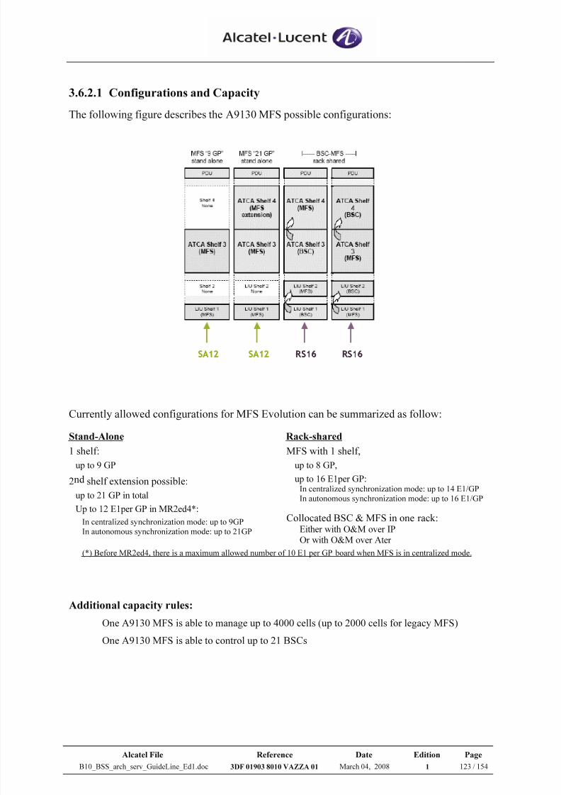
7/21/2019 BSS Architecture Service Guideline B10
http://slidepdf.com/reader/full/bss-architecture-service-guideline-b10 123/154
Alcatel File Reference Date Edition Page
B10_BSS_arch_serv_GuideLine_Ed1.doc 3DF 01903 8010 VAZZA 01 March 04, 2008 1 123 / 154
3.6.2.1 Configurations and Capacity
The following figure describes the A9130 MFS possible configurations:
SA12 SA12 RS16 RS16SA12 SA12 RS16 RS16
Currently allowed configurations for MFS Evolution can be summarized as follow:
Stand-Alone Rack-shared
1 shelf:
up to 9 GP
2nd shelf extension possible:
up to 21 GP in total
Up to 12 E1per GP in MR2ed4*:
In centralized synchronization mode: up to 9GP
In autonomous synchronization mode: up to 21GP
MFS with 1 shelf,
up to 8 GP,
up to 16 E1per GP:In centralized synchronization mode: up to 14 E1/GP
In autonomous synchronization mode: up to 16 E1/GP
Collocated BSC & MFS in one rack:Either with O&M over IPOr with O&M over Ater
(*) Before MR2ed4, there is a maximum allowed number of 10 E1 per GP board when MFS is in centralized mode.
Additional capacity rules:
One A9130 MFS is able to manage up to 4000 cells (up to 2000 cells for legacy MFS)
One A9130 MFS is able to control up to 21 BSCs
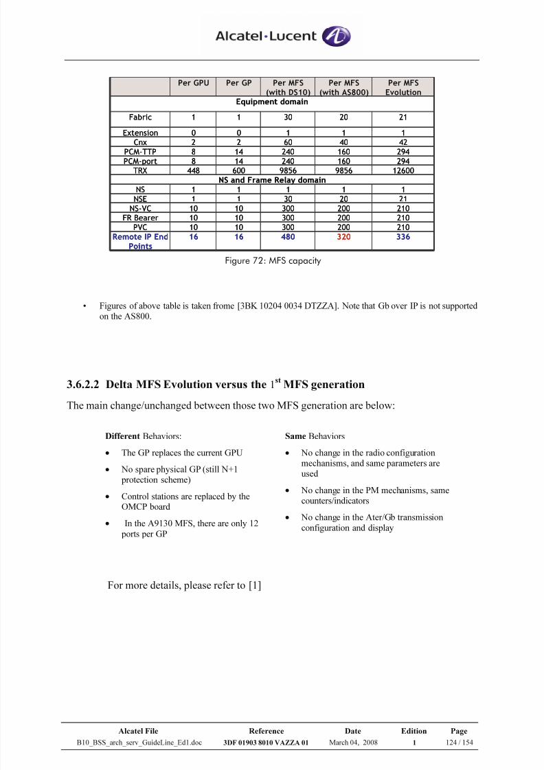
7/21/2019 BSS Architecture Service Guideline B10
http://slidepdf.com/reader/full/bss-architecture-service-guideline-b10 124/154
Alcatel File Reference Date Edition Page
B10_BSS_arch_serv_GuideLine_Ed1.doc 3DF 01903 8010 VAZZA 01 March 04, 2008 1 124 / 154
3363204801616Remote IP EndPoints
2102003001010PVC
2102003001010FR Bearer2102003001010NS-VC
21203011NSE
11111NS
NS and Frame Relay domain1260098569856600448TRX294160240148PCM-port
294160240148PCM-TTP
42406022Cnx11100Extension
21203011Fabric
Equipment domain
Per MFSEvolution
Per MFS(with AS800)
Per MFS(with DS10)
Per GPPer GPU
Figure 72: MFS capacity
• Figures of above table is taken frome [3BK 10204 0034 DTZZA]. Note that Gb over IP is not supportedon the AS800.
3.6.2.2 Delta MFS Evolution versus the 1st
MFS generation
The main change/unchanged between those two MFS generation are below:
For more details, please refer to [1]
Different Behaviors:
• The GP replaces the current GPU
• No spare physical GP (still N+1protection scheme)
• Control stations are replaced by theOMCP board
• In the A9130 MFS, there are only 12
ports per GP
Same Behaviors
• No change in the radio configurationmechanisms, and same parameters areused
• No change in the PM mechanisms, samecounters/indicators
• No change in the Ater/Gb transmission
configuration and display
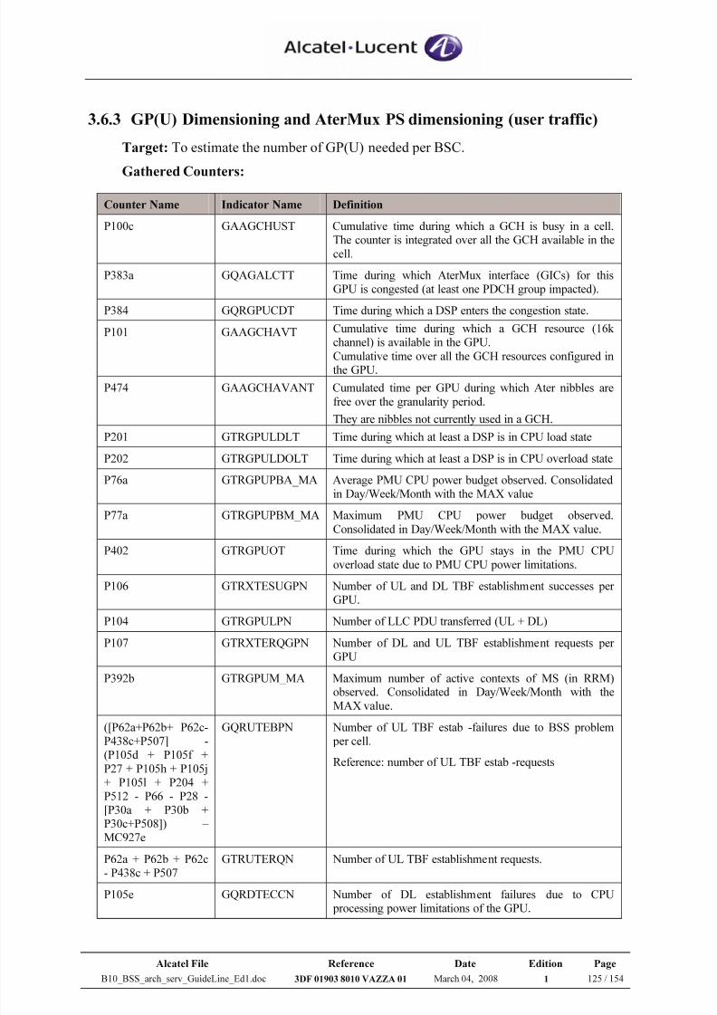
7/21/2019 BSS Architecture Service Guideline B10
http://slidepdf.com/reader/full/bss-architecture-service-guideline-b10 125/154
Alcatel File Reference Date Edition Page
B10_BSS_arch_serv_GuideLine_Ed1.doc 3DF 01903 8010 VAZZA 01 March 04, 2008 1 125 / 154
3.6.3 GP(U) Dimensioning and AterMux PS dimensioning (user traffic)
Target: To estimate the number of GP(U) needed per BSC.
Gathered Counters:
Counter Name Indicator Name Definition
P100c GAAGCHUST Cumulative time during which a GCH is busy in a cell.The counter is integrated over all the GCH available in the
cell.
P383a GQAGALCTT Time during which AterMux interface (GICs) for thisGPU is congested (at least one PDCH group impacted).
P384 GQRGPUCDT Time during which a DSP enters the congestion state.
P101 GAAGCHAVT Cumulative time during which a GCH resource (16kchannel) is available in the GPU.
Cumulative time over all the GCH resources configured inthe GPU.
P474 GAAGCHAVANT Cumulated time per GPU during which Ater nibbles are
free over the granularity period.
They are nibbles not currently used in a GCH.
P201 GTRGPULDLT Time during which at least a DSP is in CPU load state
P202 GTRGPULDOLT Time during which at least a DSP is in CPU overload state
P76a GTRGPUPBA_MA Average PMU CPU power budget observed. Consolidatedin Day/Week/Month with the MAX value
P77a GTRGPUPBM_MA Maximum PMU CPU power budget observed.
Consolidated in Day/Week/Month with the MAX value.P402 GTRGPUOT Time during which the GPU stays in the PMU CPU
overload state due to PMU CPU power limitations.
P106 GTRXTESUGPN Number of UL and DL TBF establishment successes perGPU.
P104 GTRGPULPN Number of LLC PDU transferred (UL + DL)
P107 GTRXTERQGPN Number of DL and UL TBF establishment requests perGPU
P392b GTRGPUM_MA Maximum number of active contexts of MS (in RRM)observed. Consolidated in Day/Week/Month with the
MAX value.([P62a+P62b+ P62c-P438c+P507] -(P105d + P105f +
P27 + P105h + P105j+ P105l + P204 +P512 - P66 - P28 -[P30a + P30b +P30c+P508]) – MC927e
GQRUTEBPN Number of UL TBF estab -failures due to BSS problemper cell.
Reference: number of UL TBF estab -requests
P62a + P62b + P62c- P438c + P507
GTRUTERQN Number of UL TBF establishment requests.
P105e GQRDTECCN Number of DL establishment failures due to CPUprocessing power limitations of the GPU.
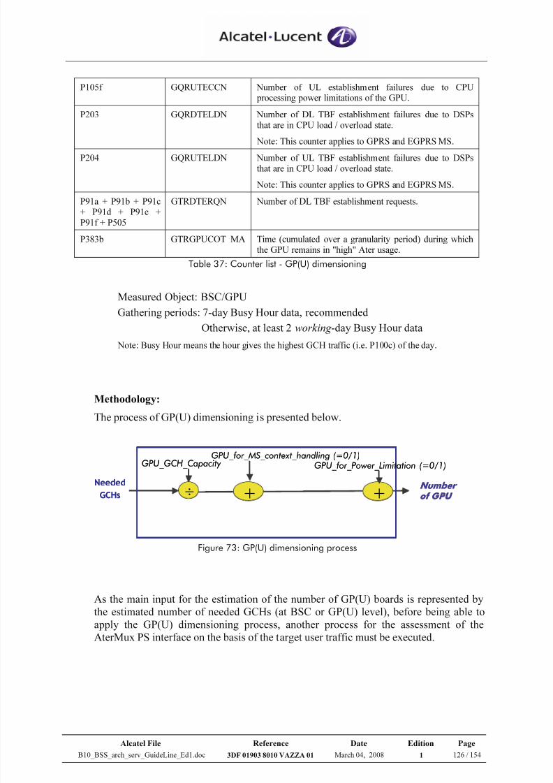
7/21/2019 BSS Architecture Service Guideline B10
http://slidepdf.com/reader/full/bss-architecture-service-guideline-b10 126/154
Alcatel File Reference Date Edition Page
B10_BSS_arch_serv_GuideLine_Ed1.doc 3DF 01903 8010 VAZZA 01 March 04, 2008 1 126 / 154
P105f GQRUTECCN Number of UL establishment failures due to CPUprocessing power limitations of the GPU.
P203 GQRDTELDN Number of DL TBF establishment failures due to DSPsthat are in CPU load / overload state.
Note: This counter applies to GPRS and EGPRS MS.
P204 GQRUTELDN Number of UL TBF establishment failures due to DSPsthat are in CPU load / overload state.
Note: This counter applies to GPRS and EGPRS MS.
P91a + P91b + P91c+ P91d + P91e +
P91f + P505
GTRDTERQN Number of DL TBF establishment requests.
P383b GTRGPUCOT_MA Time (cumulated over a granularity period) during whichthe GPU remains in "high" Ater usage.
Table 37: Counter list - GP(U) dimensioning
Measured Object: BSC/GPU
Gathering periods: 7-day Busy Hour data, recommended
Otherwise, at least 2 working -day Busy Hour data
Note: Busy Hour means the hour gives the highest GCH traffic (i.e. P100c) of the day.
Methodology:
The process of GP(U) dimensioning is presented below.
Number
of GPU
GPU_GCH_Capacity
÷
GPU_for_MS_context_handling (=0/1)
Needed
GCHs +
GPU_for_Power_Limitation (=0/1)
+Number
of GPU
GPU_GCH_Capacity
÷
GPU_for_MS_context_handling (=0/1)
Needed
GCHs +
GPU_for_Power_Limitation (=0/1)
+
Figure 73: GP(U) dimensioning process
As the main input for the estimation of the number of GP(U) boards is represented by
the estimated number of needed GCHs (at BSC or GP(U) level), before being able to
apply the GP(U) dimensioning process, another process for the assessment of the
AterMux PS interface on the basis of the target user traffic must be executed.
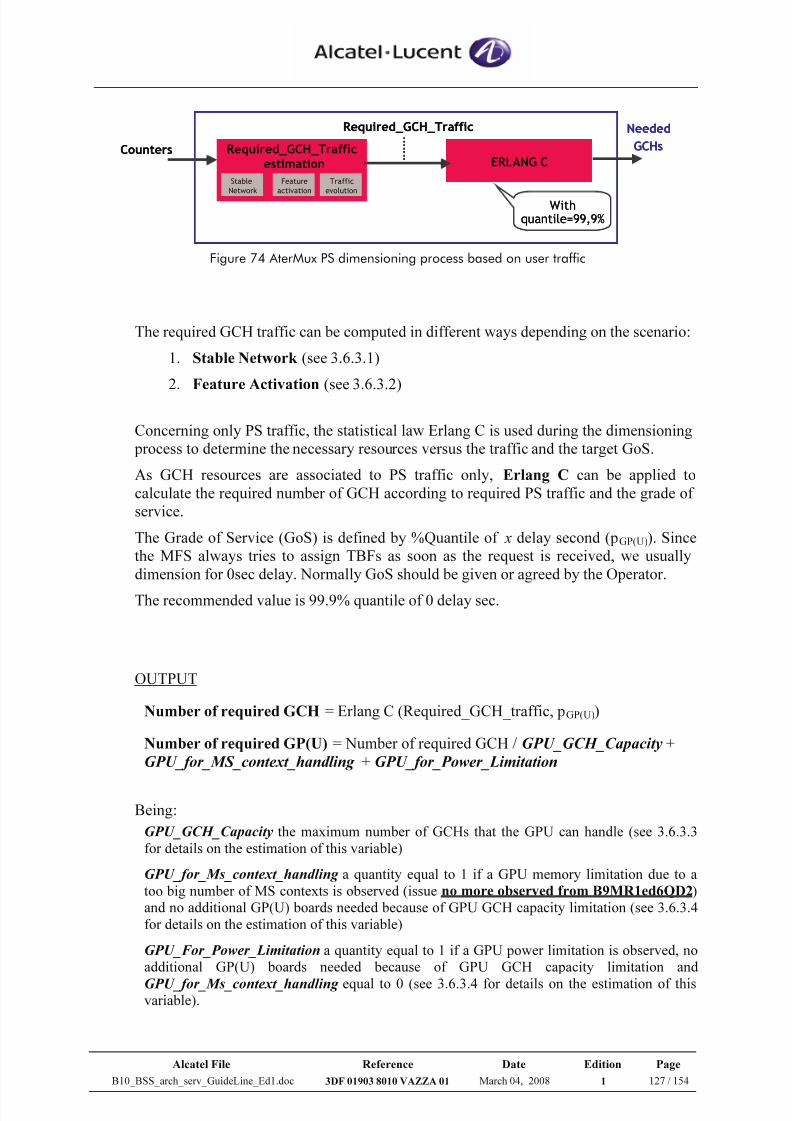
7/21/2019 BSS Architecture Service Guideline B10
http://slidepdf.com/reader/full/bss-architecture-service-guideline-b10 127/154
Alcatel File Reference Date Edition Page
B10_BSS_arch_serv_GuideLine_Ed1.doc 3DF 01903 8010 VAZZA 01 March 04, 2008 1 127 / 154
ERLANG CCounters
Required_GCH_Traffic Needed
GCHs
Withquantile=99,9%
Feature
activation
Traffic
evolution
Stable
Network
Required_GCH_Trafficestimation ERLANG C
Counters
Required_GCH_Traffic Needed
GCHs
Withquantile=99,9%
Feature
activation
Traffic
evolution
Stable
Network
Required_GCH_Trafficestimation
Feature
activation
Traffic
evolution
Stable
Network
Required_GCH_Trafficestimation
Figure 74 AterMux PS dimensioning process based on user traffic
The required GCH traffic can be computed in different ways depending on the scenario:
1. Stable Network (see 3.6.3.1)
2. Feature Activation (see 3.6.3.2)
Concerning only PS traffic, the statistical law Erlang C is used during the dimensioning
process to determine the necessary resources versus the traffic and the target GoS.
As GCH resources are associated to PS traffic only, Erlang C can be applied to
calculate the required number of GCH according to required PS traffic and the grade of
service.
The Grade of Service (GoS) is defined by %Quantile of x delay second (pGP(U)). Since
the MFS always tries to assign TBFs as soon as the request is received, we usually
dimension for 0sec delay. Normally GoS should be given or agreed by the Operator.
The recommended value is 99.9% quantile of 0 delay sec.
OUTPUT
Number of required GCH = Erlang C (Required_GCH_traffic, pGP(U))
Number of required GP(U) = Number of required GCH / GPU_GCH_Capacity +
GPU_for_MS_context_handling + GPU_for_Power_Limitation
Being:
GPU_GCH_Capacity the maximum number of GCHs that the GPU can handle (see 3.6.3.3
for details on the estimation of this variable)
GPU_for_Ms_context_handling a quantity equal to 1 if a GPU memory limitation due to a
too big number of MS contexts is observed (issue no more observed from B9MR1ed6QD2)
and no additional GP(U) boards needed because of GPU GCH capacity limitation (see 3.6.3.4
for details on the estimation of this variable)
GPU_For_Power_Limitation a quantity equal to 1 if a GPU power limitation is observed, no
additional GP(U) boards needed because of GPU GCH capacity limitation and
GPU_for_Ms_context_handling equal to 0 (see 3.6.3.4 for details on the estimation of thisvariable).
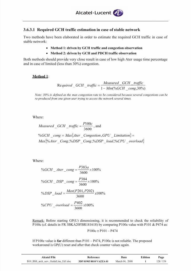
7/21/2019 BSS Architecture Service Guideline B10
http://slidepdf.com/reader/full/bss-architecture-service-guideline-b10 128/154
Alcatel File Reference Date Edition Page
B10_BSS_arch_serv_GuideLine_Ed1.doc 3DF 01903 8010 VAZZA 01 March 04, 2008 1 128 / 154
3.6.3.1 Required GCH traffic estimation in case of stable network
Two methods have been elaborated in order to estimate the required GCH traffic in case of
stable network:
• Method 1: driven by GCH traffic and congestion observation
• Method 2: driven by GCH and PDCH traffic observation
Both methods should provide very close result in case of low high Ater usage time percentage
and in case of limited (less than 30%) congestion.
Method 1:
%)30, _ (%1
_ _ _ _ Re
cong GCH Min
trafficGCH Measured trafficGCH quired
−
=
Note: 30% is defined as the max congestion rate to be considered because several congestions can bere-produced from one given user trying to access the network several times.
Where:
3600
100 _ _
c P trafficGCH Measured = , and
{ }
{ }overload CPU load DSP Cong DSP Cong Ater Max
LimitationGPU Congestion Ater Maxcong GCH
_ ,% _ ,% _ ,% _ %
_ , _ _ % ==
Where:
%1003600
383 _ _ % ×=
a P cong Ater GCH
%1003600
384 _ _ % ×=
P cong DSP GCH
%1003600
)202,201( _ % x
P P Maxload DSP =
%1003600
402 _ % x
P overload CPU =
Remark: Before starting GP(U) dimensioning, it is recommended to check the reliability of P100c (cf. details in FR 3BKA20FBR181618) by comparing P100c value with P101 & P474 as:
P100c ≅ P101 – P474
If P100c value is far different than P101 – P474, P100c is not reliable. The proposed workaround is GP(U) reset and after that check counter values again.
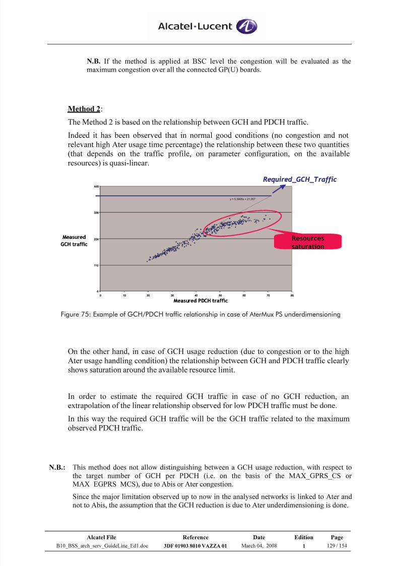
7/21/2019 BSS Architecture Service Guideline B10
http://slidepdf.com/reader/full/bss-architecture-service-guideline-b10 129/154
Alcatel File Reference Date Edition Page
B10_BSS_arch_serv_GuideLine_Ed1.doc 3DF 01903 8010 VAZZA 01 March 04, 2008 1 129 / 154
N.B. If the method is applied at BSC level the congestion will be evaluated as themaximum congestion over all the connected GP(U) boards.
Method 2:
The Method 2 is based on the relationship between GCH and PDCH traffic.
Indeed it has been observed that in normal good conditions (no congestion and not
relevant high Ater usage time percentage) the relationship between these two quantities
(that depends on the traffic profile, on parameter configuration, on the available
resources) is quasi-linear.
y = 5,3905x + 21,057
0
112
224
336
448
0 10 20 30 40 50 60 70 80
Measured PDCH traffic
Measured
GCH traffic
Resources
saturation
Required_GCH_Traffic
y = 5,3905x + 21,057
0
112
224
336
448
0 10 20 30 40 50 60 70 80
Measured PDCH traffic
Measured
GCH traffic
Resources
saturation
Required_GCH_Traffic
Figure 75: Example of GCH/PDCH traffic relationship in case of AterMux PS underdimensioning
On the other hand, in case of GCH usage reduction (due to congestion or to the high
Ater usage handling condition) the relationship between GCH and PDCH traffic clearly
shows saturation around the available resource limit.
In order to estimate the required GCH traffic in case of no GCH reduction, anextrapolation of the linear relationship observed for low PDCH traffic must be done.
In this way the required GCH traffic will be the GCH traffic related to the maximum
observed PDCH traffic.
N.B.: This method does not allow distinguishing between a GCH usage reduction, with respect tothe target number of GCH per PDCH (i.e. on the basis of the MAX_GPRS_CS orMAX_EGPRS_MCS), due to Abis or Ater congestion.
Since the major limitation observed up to now in the analysed networks is linked to Ater and not to Abis, the assumption that the GCH reduction is due to Ater underdimensioning is done.
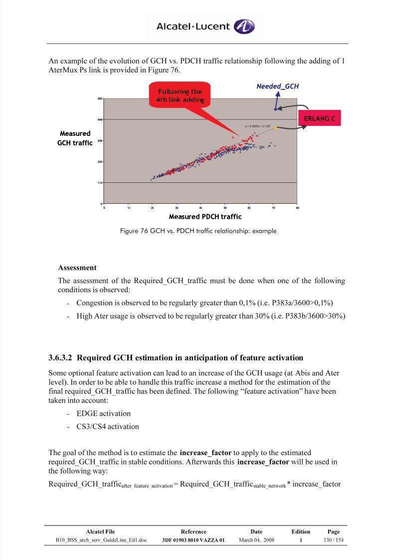
7/21/2019 BSS Architecture Service Guideline B10
http://slidepdf.com/reader/full/bss-architecture-service-guideline-b10 130/154
Alcatel File Reference Date Edition Page
B10_BSS_arch_serv_GuideLine_Ed1.doc 3DF 01903 8010 VAZZA 01 March 04, 2008 1 130 / 154
An example of the evolution of GCH vs. PDCH traffic relationship following the adding of 1
AterMux Ps link is provided in Figure 76.
y = 5,3905x + 21,057
0
112
224
336
448
560
0 10 20 30 40 50 60 70 80
Measured
GCH traffic
Measured PDCH traffic
Following the
4th link adding
ERLANG C
Needed_GCH
y = 5,3905x + 21,057
0
112
224
336
448
560
0 10 20 30 40 50 60 70 80
Measured
GCH traffic
Measured PDCH traffic
Following the
4th link adding
ERLANG C
Needed_GCH
Figure 76 GCH vs. PDCH traffic relationship: example
Assessment
The assessment of the Required_GCH_traffic must be done when one of the following
conditions is observed:
- Congestion is observed to be regularly greater than 0,1% (i.e. P383a/3600>0,1%)
- High Ater usage is observed to be regularly greater than 30% (i.e. P383b/3600>30%)
3.6.3.2 Required GCH estimation in anticipation of feature activation
Some optional feature activation can lead to an increase of the GCH usage (at Abis and Ater
level). In order to be able to handle this traffic increase a method for the estimation of the
final required_GCH_traffic has been defined. The following “feature activation” have beentaken into account:
- EDGE activation
- CS3/CS4 activation
The goal of the method is to estimate the increase_factor to apply to the estimated
required_GCH_traffic in stable conditions. Afterwards this increase_factor will be used in
the following way:
Required_GCH_trafficafter_feature_activation = Required_GCH_trafficstable_network * increase_factor
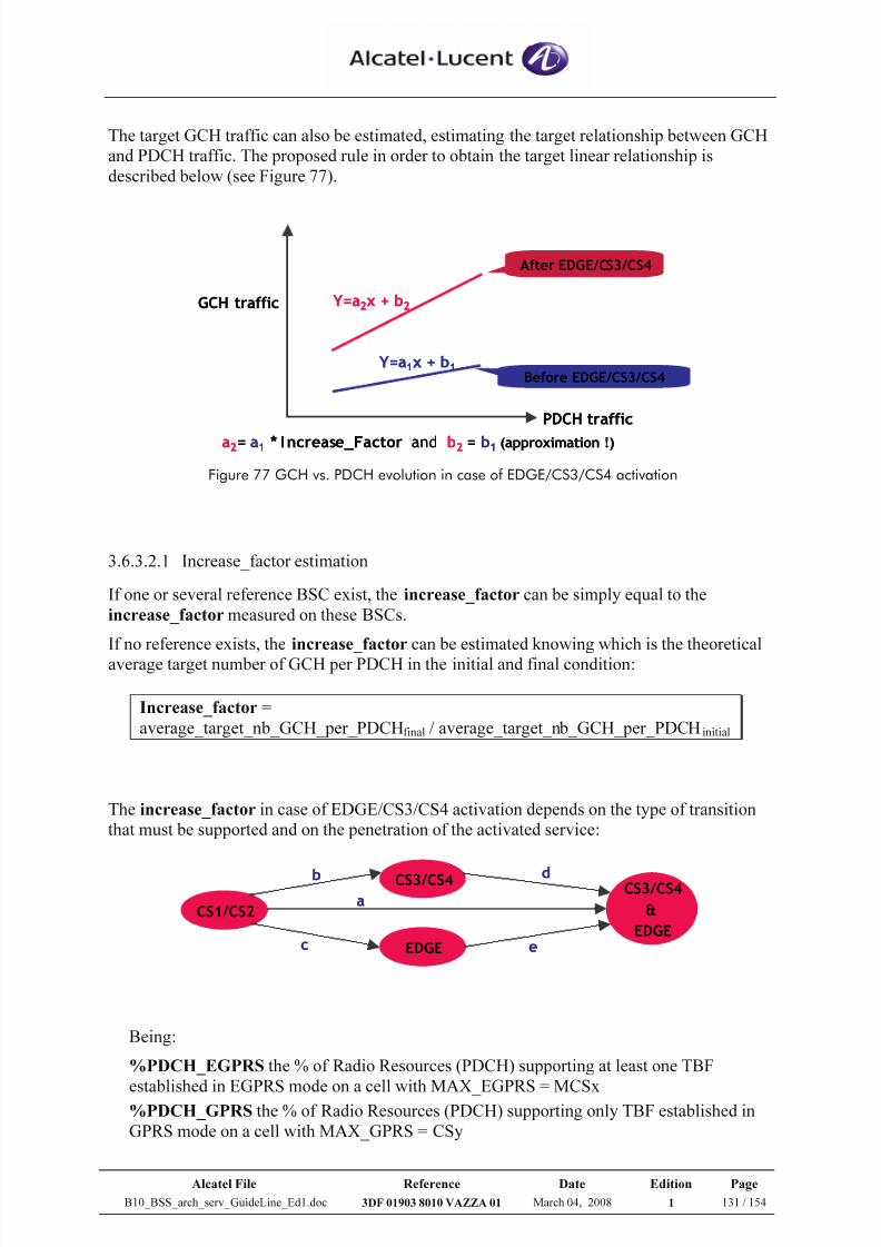
7/21/2019 BSS Architecture Service Guideline B10
http://slidepdf.com/reader/full/bss-architecture-service-guideline-b10 131/154
Alcatel File Reference Date Edition Page
B10_BSS_arch_serv_GuideLine_Ed1.doc 3DF 01903 8010 VAZZA 01 March 04, 2008 1 131 / 154
The target GCH traffic can also be estimated, estimating the target relationship between GCH
and PDCH traffic. The proposed rule in order to obtain the target linear relationship is
described below (see Figure 77).
Before EDGE/CS3/CS4
After EDGE/CS3/CS4
Y=a2x + b2
Y=a1x + b1
a2= a1 * Increase_Factor and b2 = b1 (approximation !)
PDCH traffic
GCH traffic
Before EDGE/CS3/CS4
After EDGE/CS3/CS4
Y=a2x + b2
Y=a1x + b1
a2= a1 * Increase_Factor and b2 = b1 (approximation !)
PDCH traffic
GCH traffic
Figure 77 GCH vs. PDCH evolution in case of EDGE/CS3/CS4 activation
3.6.3.2.1 Increase_factor estimation
If one or several reference BSC exist, the increase_factor can be simply equal to the
increase_factor measured on these BSCs.
If no reference exists, the increase_factor can be estimated knowing which is the theoretical
average target number of GCH per PDCH in the initial and final condition:
Increase_factor =
average_target_nb_GCH_per_PDCHfinal / average_target_nb_GCH_per_PDCHinitial
The increase_factor in case of EDGE/CS3/CS4 activation depends on the type of transition
that must be supported and on the penetration of the activated service:
CS1/CS2
CS3/CS4CS3/CS4
&
EDGE
EDGE
a
b
c
d
e
CS1/CS2
CS3/CS4CS3/CS4
&
EDGE
EDGE
a
b
c
d
e
Being:
%PDCH_EGPRS the % of Radio Resources (PDCH) supporting at least one TBF
established in EGPRS mode on a cell with MAX_EGPRS = MCSx%PDCH_GPRS the % of Radio Resources (PDCH) supporting only TBF established in
GPRS mode on a cell with MAX_GPRS = CSy
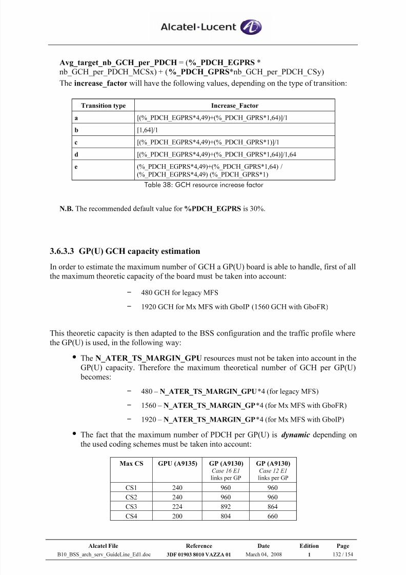
7/21/2019 BSS Architecture Service Guideline B10
http://slidepdf.com/reader/full/bss-architecture-service-guideline-b10 132/154
Alcatel File Reference Date Edition Page
B10_BSS_arch_serv_GuideLine_Ed1.doc 3DF 01903 8010 VAZZA 01 March 04, 2008 1 132 / 154
Avg_target_nb_GCH_per_PDCH = (%_PDCH_EGPRS *
nb_GCH_per_PDCH_MCSx) + (%_PDCH_GPRS*nb_GCH_per_PDCH_CSy)
The increase_factor will have the following values, depending on the type of transition:
Transition type Increase_Factor
a [(%_PDCH_EGPRS*4,49)+(%_PDCH_GPRS*1,64)]/1
b [1,64]/1
c [(%_PDCH_EGPRS*4,49)+(%_PDCH_GPRS*1)]/1
d [(%_PDCH_EGPRS*4,49)+(%_PDCH_GPRS*1,64)]/1,64
e (%_PDCH_EGPRS*4,49)+(%_PDCH_GPRS*1,64) /
(%_PDCH_EGPRS*4,49) (%_PDCH_GPRS*1)
Table 38: GCH resource increase factor
N.B. The recommended default value for %PDCH_EGPRS is 30%.
3.6.3.3 GP(U) GCH capacity estimation
In order to estimate the maximum number of GCH a GP(U) board is able to handle, first of all
the maximum theoretic capacity of the board must be taken into account:
– 480 GCH for legacy MFS
–1920 GCH for Mx MFS with GboIP (1560 GCH with GboFR)
This theoretic capacity is then adapted to the BSS configuration and the traffic profile where
the GP(U) is used, in the following way:
The N_ATER_TS_MARGIN_GPU resources must not be taken into account in the
GP(U) capacity. Therefore the maximum theoretical number of GCH per GP(U)
becomes:
– 480 – N_ATER_TS_MARGIN_GPU*4 (for legacy MFS)
–
1560 – N_ATER_TS_MARGIN_GP*4 (for Mx MFS with GboFR)
– 1920 – N_ATER_TS_MARGIN_GP*4 (for Mx MFS with GboIP)
The fact that the maximum number of PDCH per GP(U) is dynamic depending on
the used coding schemes must be taken into account:
Max CS GPU (A9135) GP (A9130)Case 16 E1
links per GP
GP (A9130)Case 12 E1
links per GP
CS1 240 960 960
CS2 240 960 960
CS3 224 892 864
CS4 200 804 660
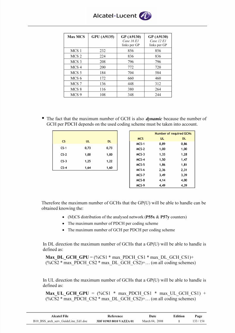
7/21/2019 BSS Architecture Service Guideline B10
http://slidepdf.com/reader/full/bss-architecture-service-guideline-b10 133/154
Alcatel File Reference Date Edition Page
B10_BSS_arch_serv_GuideLine_Ed1.doc 3DF 01903 8010 VAZZA 01 March 04, 2008 1 133 / 154
Max MCS GPU (A9135) GP (A9130)Case 16 E1
links per GP
GP (A9130)Case 12 E1
links per GP
MCS 1 232 856 856
MCS 2 224 836 836
MCS 3 208 796 796
MCS 4 200 772 720
MCS 5 184 704 584
MCS 6 172 660 460
MCS 7 136 448 312
MCS 8 116 380 264
MCS 9 108 348 244
The fact that the maximum number of GCH is also dynamic because the number of
GCH per PDCH depends on the used coding scheme must be taken into account.
1,601,64CS-4
1,221,25CS-3
1,001,00CS-2
0,730,73CS-1
DLULCS
1,601,64CS-4
1,221,25CS-3
1,001,00CS-2
0,730,73CS-1
DLULCS
4,394,49MCS-9
4,004,14MCS-8
3,393,49MCS-7
2,312,36MCS-6
1,811,86MCS-5
1,471,50MCS-4
1,281,33MCS-3
1,001,00MCS-2
0,860,89MCS-1
DLULMCS
Number of required GCHs
4,394,49MCS-9
4,004,14MCS-8
3,393,49MCS-7
2,312,36MCS-6
1,811,86MCS-5
1,471,50MCS-4
1,281,33MCS-3
1,001,00MCS-2
0,860,89MCS-1
DLULMCS
Number of required GCHs
Therefore the maximum number of GCHs that the GP(U) will be able to handle can be
obtained knowing the:
• (M)CS distribution of the analysed network (P55x & P57y counters)
• The maximum number of PDCH per coding scheme
• The maximum number of GCH per PDCH per coding scheme
In DL direction the maximum number of GCHs that a GP(U) will be able to handle is
defined as:
Max_DL_GCH_GPU = (%CS1 * max_PDCH_CS1 * max_DL_GCH_CS1)+
(%CS2 * max_PDCH_CS2 * max_DL_GCH_CS2)+… (on all coding schemes)
In UL direction the maximum number of GCHs that a GP(U) will be able to handle is
defined as:
Max_UL_GCH_GPU = (%CS1 * max_PDCH_CS1 * max_UL_GCH_CS1) +(%CS2 * max_PDCH_CS2 * max_DL_GCH_CS2)+… (on all coding schemes)
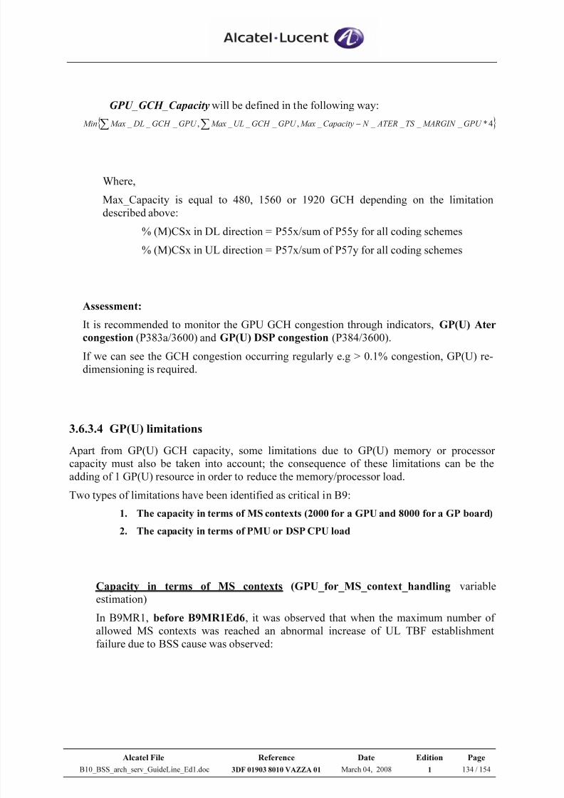
7/21/2019 BSS Architecture Service Guideline B10
http://slidepdf.com/reader/full/bss-architecture-service-guideline-b10 134/154
Alcatel File Reference Date Edition Page
B10_BSS_arch_serv_GuideLine_Ed1.doc 3DF 01903 8010 VAZZA 01 March 04, 2008 1 134 / 154
GPU_GCH_Capacitywill be defined in the following way:
{ }∑ ∑ − 4* _ _ _ _ _ , _ _ _ , _ _ _ GPU MARGIN TS ATER N Capacity MaxGPU GCH UL MaxGPU GCH DL Max Min
Where,
Max_Capacity is equal to 480, 1560 or 1920 GCH depending on the limitation
described above:
% (M)CSx in DL direction = P55x/sum of P55y for all coding schemes
% (M)CSx in UL direction = P57x/sum of P57y for all coding schemes
Assessment:
It is recommended to monitor the GPU GCH congestion through indicators, GP(U) Ater
congestion (P383a/3600) and GP(U) DSP congestion (P384/3600).
If we can see the GCH congestion occurring regularly e.g > 0.1% congestion, GP(U) re-
dimensioning is required.
3.6.3.4 GP(U) limitations
Apart from GP(U) GCH capacity, some limitations due to GP(U) memory or processor
capacity must also be taken into account; the consequence of these limitations can be the
adding of 1 GP(U) resource in order to reduce the memory/processor load.
Two types of limitations have been identified as critical in B9:
1. The capacity in terms of MS contexts (2000 for a GPU and 8000 for a GP board)
2. The capacity in terms of PMU or DSP CPU load
Capacity in terms of MS contexts (GPU_for_MS_context_handling variable
estimation)
In B9MR1, before B9MR1Ed6, it was observed that when the maximum number of
allowed MS contexts was reached an abnormal increase of UL TBF establishment
failure due to BSS cause was observed:
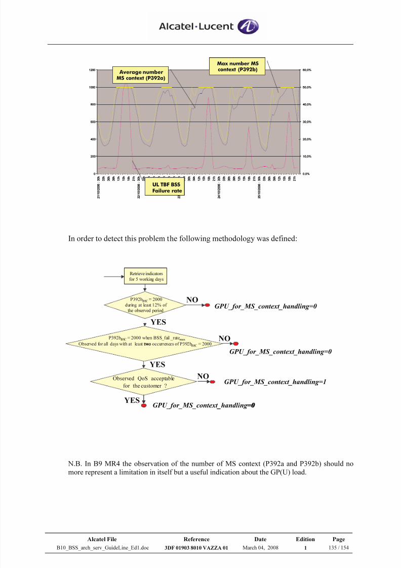
7/21/2019 BSS Architecture Service Guideline B10
http://slidepdf.com/reader/full/bss-architecture-service-guideline-b10 135/154
Alcatel File Reference Date Edition Page
B10_BSS_arch_serv_GuideLine_Ed1.doc 3DF 01903 8010 VAZZA 01 March 04, 2008 1 135 / 154
0
200
400
600
800
1000
1200
2 1 / 1 0 / 2 0 0 6
: 0 0 h
0 3 h
0 6 h
0 9 h
1 2 h
1 5 h
1 8 h
2 1 h
2 2 / 1 0 / 2 0 0 6
: 0 0 h
0 3 h
0 6 h
0 9 h
1 2 h
1 5 h
1 8 h
2 1 h
2 3 / 1 0 / 2 0 0 6
: 0 0 h
0 3 h
0 6 h
0 9 h
1 2 h
1 5 h
1 8 h
2 1 h
2 4 / 1 0 / 2 0 0 6
: 0 0 h
0 3 h
0 6 h
0 9 h
1 2 h
1 5 h
1 8 h
2 1 h
2 5 / 1 0 / 2 0 0 6
: 0 0 h
0 3 h
0 6 h
0 9 h
1 2 h
1 5 h
1 8 h
2 1 h
0,0%
10,0%
20,0%
30,0%
40,0%
50,0%
60,0%
UL TBF BSSFailure rate
Average numberMS context (P392a)
Max number MScontext (P392b)
In order to detect this problem the following methodology was defined:
Retrieve indicators
for 5 working days
P392bBSC= 2000during at least 12% of
the observed period
NO
YES
P392bBSC
= 2000 when BSS_fail _ratemax
Observed for all days with at least two occurrences of P392bBSC
= 2000
Observed QoS acceptable
for the customer ?
YES
YES
NO
NO
GPU_for_MS_context_handling=0
GPU_for_MS_context_handling=0
GPU_for_MS_context_handling=1
GPU_for_MS_context_handling=0
Retrieve indicators
for 5 working days
two
_
_
_ =0
N.B. In B9 MR4 the observation of the number of MS context (P392a and P392b) should nomore represent a limitation in itself but a useful indication about the GP(U) load.
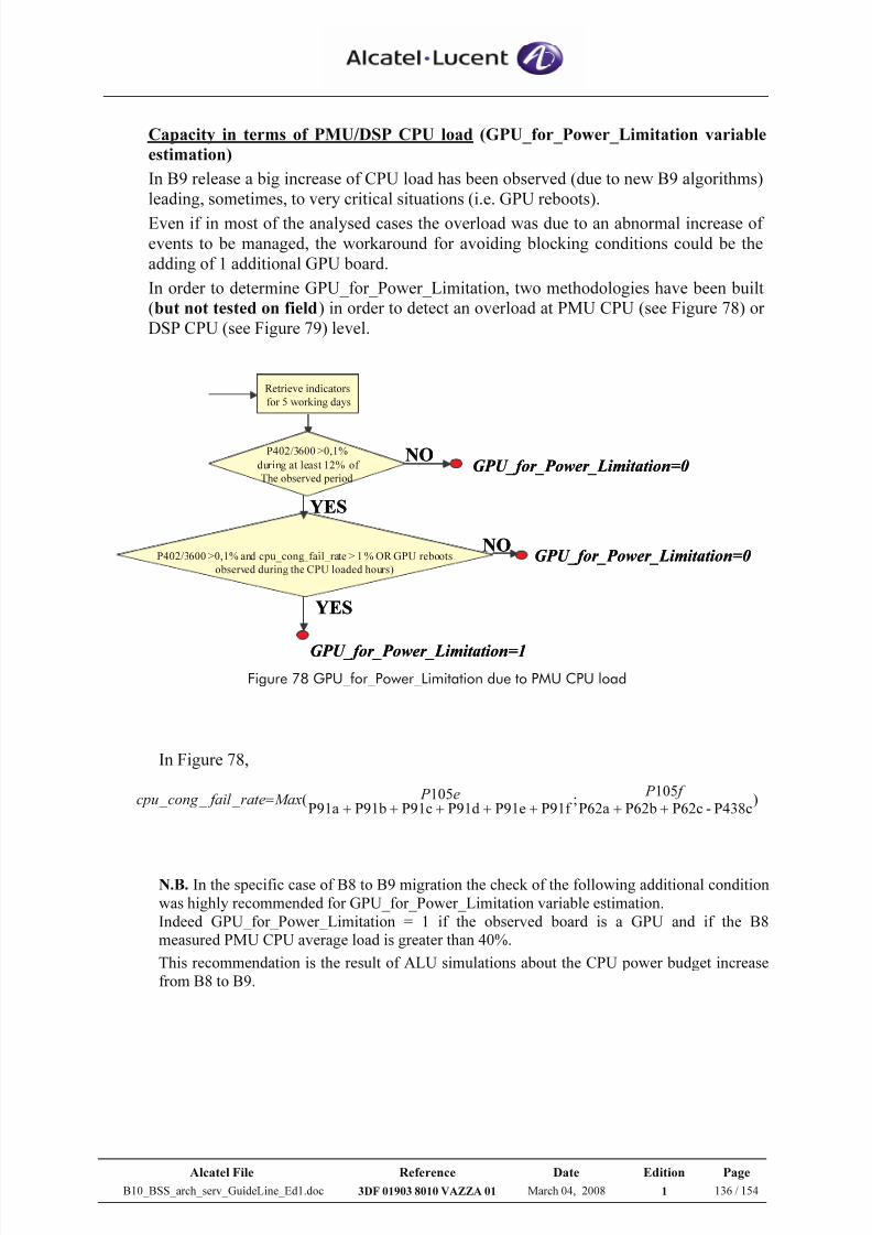
7/21/2019 BSS Architecture Service Guideline B10
http://slidepdf.com/reader/full/bss-architecture-service-guideline-b10 136/154
Alcatel File Reference Date Edition Page
B10_BSS_arch_serv_GuideLine_Ed1.doc 3DF 01903 8010 VAZZA 01 March 04, 2008 1 136 / 154
Capacity in terms of PMU/DSP CPU load (GPU_for_Power_Limitation variable
estimation)
In B9 release a big increase of CPU load has been observed (due to new B9 algorithms)
leading, sometimes, to very critical situations (i.e. GPU reboots).
Even if in most of the analysed cases the overload was due to an abnormal increase of
events to be managed, the workaround for avoiding blocking conditions could be the
adding of 1 additional GPU board.
In order to determine GPU_for_Power_Limitation, two methodologies have been built
(but not tested on field) in order to detect an overload at PMU CPU (see Figure 78) or
DSP CPU (see Figure 79) level.
Retrieve indicators
for 5 working days
P402/3600 >0,1%
during at least 12% of
The observed period
NO
YES
P402/3600 >0,1% and cpu_cong_fail_rate > 1% OR GPU reboots
observed during the CPU loaded hours)
YES
NO
GPU_for_Power_Limitation=0
GPU_for_Power_Limitation=0
GPU_for_Power_Limitation=1
Retrieve indicators
for 5 working days
P402/3600 >0,1%
during at least 12% of
The observed period
NO
YES
P402/3600 >0,1% and cpu_cong_fail_rate > 1% OR GPU reboots
observed during the CPU loaded hours)
YES
NO
GPU_for_Power_Limitation=0
GPU_for_Power_Limitation=0
GPU_for_Power_Limitation=1 Figure 78 GPU_for_Power_Limitation due to PMU CPU load
In Figure 78,
)P438c-P62cP62bP62a
105;
P91f P91eP91dP91cP91bP91a105( _ _ _
+++++++=
f P e P Maxrate fail cong cpu
N.B. In the specific case of B8 to B9 migration the check of the following additional conditionwas highly recommended for GPU_for_Power_Limitation variable estimation.Indeed GPU_for_Power_Limitation = 1 if the observed board is a GPU and if the B8measured PMU CPU average load is greater than 40%.
This recommendation is the result of ALU simulations about the CPU power budget increasefrom B8 to B9.
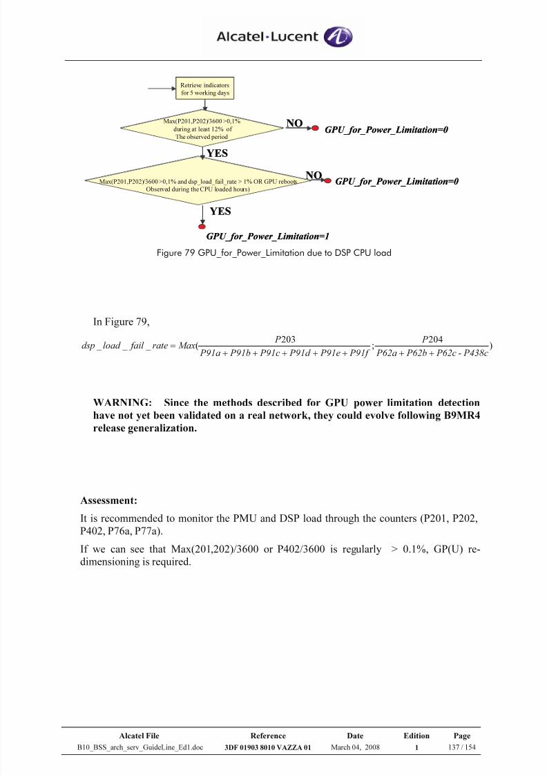
7/21/2019 BSS Architecture Service Guideline B10
http://slidepdf.com/reader/full/bss-architecture-service-guideline-b10 137/154
Alcatel File Reference Date Edition Page
B10_BSS_arch_serv_GuideLine_Ed1.doc 3DF 01903 8010 VAZZA 01 March 04, 2008 1 137 / 154
Retrieve indicators
for 5 working days
Max(P201,P202)/3600 >0,1%
during at least 12% of
The observed period
NO
YES
Max(P201,P202)/3600 >0,1% and dsp_load_fail_rate > 1% OR GPU reboots
Observed during the CPU loaded hours)
YES
NO
GPU_for_Power_Limitation=0
GPU_for_Power_Limitation=0
GPU_for_Power_Limitation=1
Retrieve indicators
for 5 working days
Max(P201,P202)/3600 >0,1%
during at least 12% of
The observed period
NO
YES
Max(P201,P202)/3600 >0,1% and dsp_load_fail_rate > 1% OR GPU reboots
Observed during the CPU loaded hours)
YES
NO
GPU_for_Power_Limitation=0
GPU_for_Power_Limitation=0
GPU_for_Power_Limitation=1 Figure 79 GPU_for_Power_Limitation due to DSP CPU load
In Figure 79,
)204
;203
( _ _ _ P438c- P62c P62b P62a
P
P91f P91e P91d P91c P91b P91a
P Maxrate fail load dsp
+++++++
=
WARNING: Since the methods described for GPU power limitation detectionhave not yet been validated on a real network, they could evolve following B9MR4
release generalization.
Assessment:
It is recommended to monitor the PMU and DSP load through the counters (P201, P202,
P402, P76a, P77a).
If we can see that Max(201,202)/3600 or P402/3600 is regularly > 0.1%, GP(U) re-
dimensioning is required.
7/21/2019 BSS Architecture Service Guideline B10
http://slidepdf.com/reader/full/bss-architecture-service-guideline-b10 138/154
Alcatel File Reference Date Edition Page
B10_BSS_arch_serv_GuideLine_Ed1.doc 3DF 01903 8010 VAZZA 01 March 04, 2008 1 138 / 154
3.7 Gb interface
As explained previously, the Gb interface allows the exchange of PS signalling and traffic
data between MFS and SGSN.
The Gb interface is defined by the three main protocols:
• BSSGP protocol
• Network Service (NS) protocol
• Physical Layer protocol
The BSSGP application layer is in charge of the processing of the packet traffic coming from
a set of radio cells. It manages the Gb interface and the BSSGP Virtual Connections (BVC).
The BVC is a virtual end-to-end path between BSSGP peer entities.
The BSSGP application layer relies on Network Service layer that manages the
communication paths between the Network Service Entity (NSE) of the SGSN and the MFS.
The Network Service layer is composed of two sub-layers:
• Network Service Control (NSC) is independent from the intermediate transmission network used on the Gb interface and is responsible for: NS PDU transfer between BSS and SGSN: PDU
order is kept, except under exceptional circumstances
- Load-sharing (at the initiative of the sender)- NS Virtual Connections (NS-VC) management
• Sub-Network Service (SNS) is dependent on the intermediate transmission network and provides access to the intermediate network
The BVC is identified by a BVC Identifier (BVCI) that is unique in one Network Service
Entity (NSE).
An NSE, which is identified by a NSE Identifier (NSEI), is a group of communication pathscalled NS-VC.
The NSEI is an end-to-end identifier and shall be unique within a SGSN.
The BVCI together with the NSEI uniquely identifies a BVC within a SGSN.
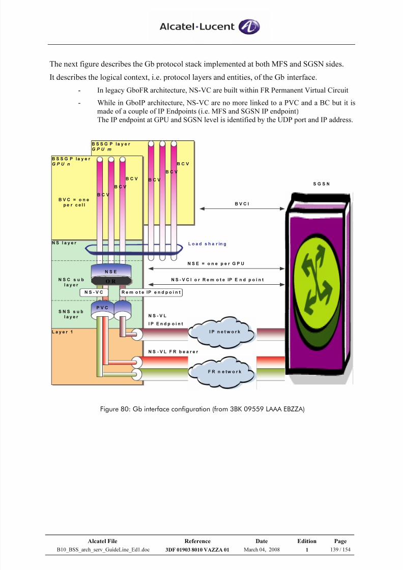
7/21/2019 BSS Architecture Service Guideline B10
http://slidepdf.com/reader/full/bss-architecture-service-guideline-b10 139/154
Alcatel File Reference Date Edition Page
B10_BSS_arch_serv_GuideLine_Ed1.doc 3DF 01903 8010 VAZZA 01 March 04, 2008 1 139 / 154
The next figure describes the Gb protocol stack implemented at both MFS and SGSN sides.
It describes the logical context, i.e. protocol layers and entities, of the Gb interface.
- In legacy GboFR architecture, NS-VC are built within FR Permanent Virtual Circuit
- While in GboIP architecture, NS-VC are no more linked to a PVC and a BC but it ismade of a couple of IP Endpoints (i.e. MFS and SGSN IP endpoint)The IP endpoint at GPU and SGSN level is identified by the UDP port and IP address.
N S la y e r
B S S G P la y e r
G P U m
B S S G P l a y e r
G P U n
L a y e r 1
B V C = o n ep e r c e l l
B C V
B C V
B C V
N S E
L o a d s h a r in g
B V C I
N S C s u b
l a y e r
S N S s u b
l a y e r
N S E = o n e p e r G P U
N S - V C I o r R e m o t e IP E n d p o i n t
I P n e t w o r k
N S - V L F R b e a r er
I P E n d p o i n t
F R n e tw o r k
S G S N
B C V
B C V
B C V
P V C
N S - V C
N S - V L
R e m o t e IP e n d p o in t
O R
Figure 80: Gb interface configuration (from 3BK 09559 LAAA EBZZA)
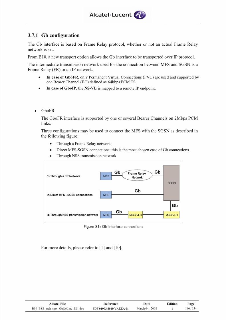
7/21/2019 BSS Architecture Service Guideline B10
http://slidepdf.com/reader/full/bss-architecture-service-guideline-b10 140/154
Alcatel File Reference Date Edition Page
B10_BSS_arch_serv_GuideLine_Ed1.doc 3DF 01903 8010 VAZZA 01 March 04, 2008 1 140 / 154
3.7.1 Gb configuration
The Gb interface is based on Frame Relay protocol, whether or not an actual Frame Relay
network is set.
From B10, a new transport option allows the Gb interface to be transported over IP protocol.
The intermediate transmission network used for the connection between MFS and SGSN is a
Frame Relay (FR) or an IP network.
• In case of GboFR , only Permanent Virtual Connections (PVC) are used and supported byone Bearer Channel (BC) defined as 64kbps PCM TS.
• In case of GboIP, the NS-VL is mapped to a remote IP endpoint.
•
GboFR The GboFR interface is supported by one or several Bearer Channels on 2Mbps PCM
links.
Three configurations may be used to connect the MFS with the SGSN as described in
the following figure:
• Through a Frame Relay network
• Direct MFS-SGSN connections: this is the most chosen case of Gb connections.
• Through NSS transmission network
1) Through a FR Network MFS
2) Direct MFS - SGSN connections MFS
3) Through NSS transmission network MFS MSC/VLR MSC/VLR
SGSN
Frame Relay
Netwok
Gb
Gb
Gb
Gb Gb
Figure 81: Gb interface connections
For more details, please refer to [1] and [10].
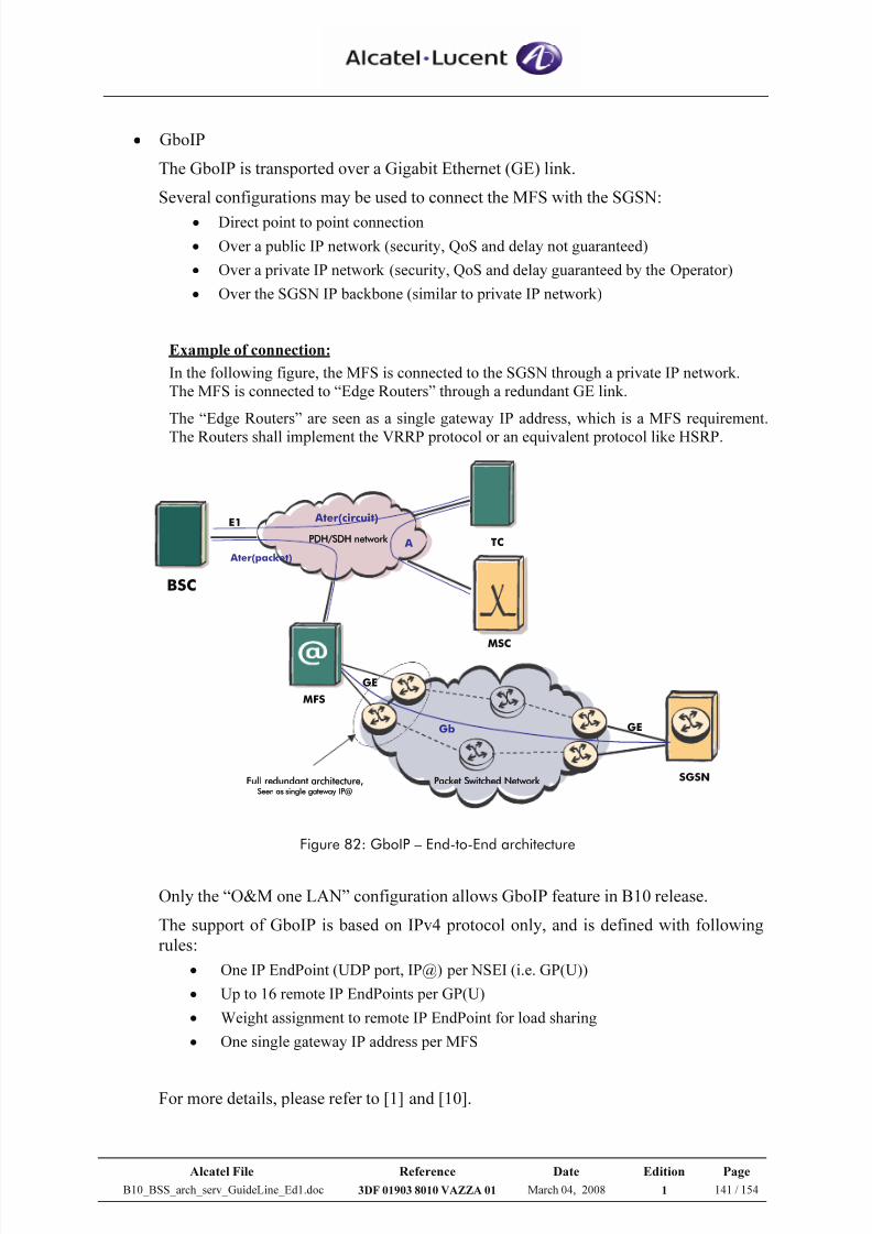
7/21/2019 BSS Architecture Service Guideline B10
http://slidepdf.com/reader/full/bss-architecture-service-guideline-b10 141/154
Alcatel File Reference Date Edition Page
B10_BSS_arch_serv_GuideLine_Ed1.doc 3DF 01903 8010 VAZZA 01 March 04, 2008 1 141 / 154
• GboIP
The GboIP is transported over a Gigabit Ethernet (GE) link.
Several configurations may be used to connect the MFS with the SGSN:
• Direct point to point connection
• Over a public IP network (security, QoS and delay not guaranteed)
• Over a private IP network (security, QoS and delay guaranteed by the Operator)
• Over the SGSN IP backbone (similar to private IP network)
Example of connection:
In the following figure, the MFS is connected to the SGSN through a private IP network.The MFS is connected to “Edge Routers” through a redundant GE link.
The “Edge Routers” are seen as a single gateway IP address, which is a MFS requirement.
The Routers shall implement the VRRP protocol or an equivalent protocol like HSRP.
PacketPacket SwitchedSwitched NetworkNetwork
PDH/SDH networkPDH/SDH network
BSC
MSC
SGSN
MFS
TC
E1
GE
GE
Ater(circuit)
Ater(packet)
A
Gb
FullFull redundantredundant architecture,architecture,SeenSeen as singleas single gateway gateway IP@IP@
Figure 82: GboIP – End-to-End architecture
Only the “O&M one LAN” configuration allows GboIP feature in B10 release.
The support of GboIP is based on IPv4 protocol only, and is defined with following
rules:
• One IP EndPoint (UDP port, IP@) per NSEI (i.e. GP(U))
• Up to 16 remote IP EndPoints per GP(U)
• Weight assignment to remote IP EndPoint for load sharing
• One single gateway IP address per MFS
For more details, please refer to [1] and [10].
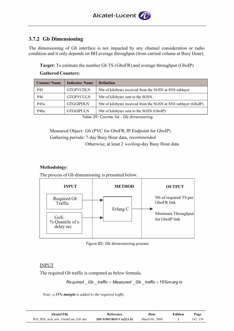
7/21/2019 BSS Architecture Service Guideline B10
http://slidepdf.com/reader/full/bss-architecture-service-guideline-b10 142/154
Alcatel File Reference Date Edition Page
B10_BSS_arch_serv_GuideLine_Ed1.doc 3DF 01903 8010 VAZZA 01 March 04, 2008 1 142 / 154
3.7.2 Gb Dimensioning
The dimensioning of Gb interface is not impacted by any channel consideration or radio
condition and it only depends on BH average throughput (from carried volume at Busy Hour).
Target: To estimate the number Gb TS (GboFR) and average throughput (GboIP)
Gathered Counters:
Counter Name Indicator Name Definition
P45 GTGPVCDLN Nbr of kilobytes received from the SGSN at SNS sublayer
P46 GTGPVCULN Nbr of kilobytes sent to the SGSN.
P45a GTGGIPDLN Nbr of kilobytes received from the SGSN at SNS sublayer (GboIP)
P46a GTGGIPULN Nbr of kilobytes sent to the SGSN (GboIP)
Table 39: Counter list - Gb dimensioning
Measured Object: Gb (PVC for GboFR, IP Endpoint for GboIP)
Gathering periods: 7-day Busy Hour data, recommended
Otherwise, at least 2 working -day Busy Hour data
Methodology:
The process of Gb dimensioning is presented below.
Figure 83: Gb dimensioning process
INPUT
The required Gb traffic is computed as below formula.
inargm%traffic _Gb _Measured traffic _Gb _quired Re 15+=
Note: a 15% margin is added to the required traffic.
Erlang C
Required GbTraffic
GoS:% Quantile of x
delay sec
Nb of required TS perGboFR link
Minimum Throughput
for GboIP link
INPUT OUTPUT METHOD
7/21/2019 BSS Architecture Service Guideline B10
http://slidepdf.com/reader/full/bss-architecture-service-guideline-b10 143/154
Alcatel File Reference Date Edition Page
B10_BSS_arch_serv_GuideLine_Ed1.doc 3DF 01903 8010 VAZZA 01 March 04, 2008 1 143 / 154
The other input is Grade of Service (GoS), which is defined by %Quantile of x delay
second (pGb).
Since the MFS always tries to assign TBFs as soon as the request is received, we
usually dimension for 0sec delay.
Normally GoS should be given or agreed by the Mobile Operator.
At high network element level Gb interface, the recommended value is 99.9% quantile
of 0 delay sec.
METHOD
Concerning only PS traffic, the statistical law Erlang C is used during the dimensioning
process to determine the necessary resources versus the traffic and the target GoS.
As Gb resources are associated to PS traffic only, Erlang C can be applied to calculatethe required number of GboFR TS and GboIP throughput according to required PS
traffic and % quantile of delay time.
OUTPUT
• Gb over Frame Relay
For GboFR interface, the measured traffic corresponds to P45 and P46 counters.
28800
4645 )P ,P ( Max traffic _Gb _Measured =
Then the required number of bearer channels (i.e. 64kbps TS) is as follows:
Number of required Gb TS per link
= Erlang C (Required_GboFR_traffic; pGb)
Notes:
1 Erlang = [Gb TS speed (64kbps) * 3600] / 8 =28800 K bytes
Minimum 2 Gb links are required for one GP(U) due to security reason
Maximum 31 Gb TS (TS no. 1 to 31) can be configured per one GboFR link. TS0cannot be used as it is reserved for specific usages e.g. frame synchronization.
In general, around 4 to 8 TS are configured per one GboFR link.
For more detail, please see [19]
7/21/2019 BSS Architecture Service Guideline B10
http://slidepdf.com/reader/full/bss-architecture-service-guideline-b10 144/154
Alcatel File Reference Date Edition Page
B10_BSS_arch_serv_GuideLine_Ed1.doc 3DF 01903 8010 VAZZA 01 March 04, 2008 1 144 / 154
• Gb over IP
The dimensioning must be performed at MFS level with all BSC involved in the
GboIP mode.
Compared to GboFR, GboIP induces an additional overhead to the Gb flow: BSSGP/NS/UDP/IP/Ethernet header is 118 bytes, while
BSSGP/NS/Frame Relay header overhead is 54 bytes
The overall overhead depends on the traffic flow characteristics (IP packets size).
As an average value, the estimated overhead is about 35% for an IP PDU of 300 bytes.
1) When the GboIP interface is used, the measured traffic is given with P45a and
P46a counters.
∑=
IP _MFS _ All
)aP ,aP ( Max traffic _GboIP _Measured
3600
4645
Then the required GboIP throughput takes into account the header as follows:
GboIP throughput required per MFS
= Erlang C (Required_GboIP_traffic+35%; pGb)
2) When Gb traffic is transported over GboFR interface and then migrated over
GboIP interface (i.e. IP), the measured traffic is given by GboFR counters.
∑=
AllPVC
P P MaxtrafficGbMeasured
28800
)46,45( _ _
The measured Gb shall take into account the removal BSSGP/NS/FR header
and the addition of the BSSGP/NS/UDP/IP/Ethernet header:
)54300/()118300(* _ _ _ _ ++= trafficGbMeasured trafficGboIP Measured
Then,
GboIP throughput required per MFS
= Erlang C (Required_GboIP_traffic; pGb)
Notes: Overhead from GboFR to GboIP = [300 + 118] / [300 + 54] = 18,1%.
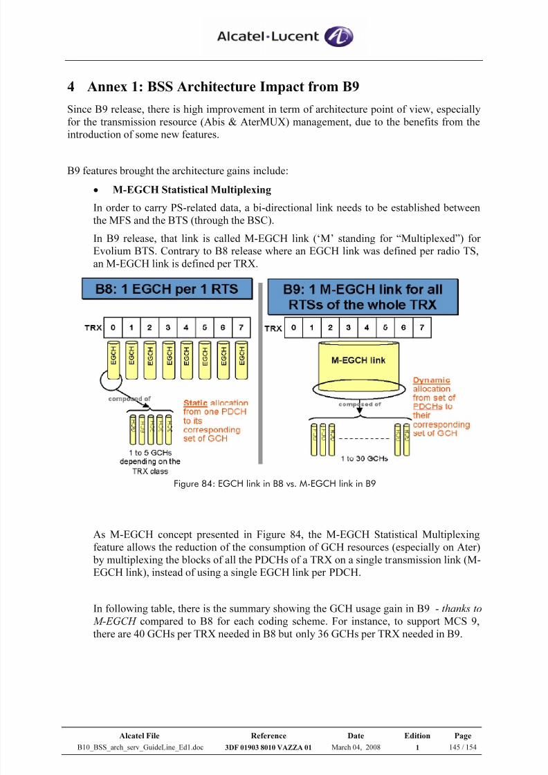
7/21/2019 BSS Architecture Service Guideline B10
http://slidepdf.com/reader/full/bss-architecture-service-guideline-b10 145/154
Alcatel File Reference Date Edition Page
B10_BSS_arch_serv_GuideLine_Ed1.doc 3DF 01903 8010 VAZZA 01 March 04, 2008 1 145 / 154
4 Annex 1: BSS Architecture Impact from B9
Since B9 release, there is high improvement in term of architecture point of view, especially
for the transmission resource (Abis & AterMUX) management, due to the benefits from the
introduction of some new features.
B9 features brought the architecture gains include:
• M-EGCH Statistical Multiplexing
In order to carry PS-related data, a bi-directional link needs to be established between
the MFS and the BTS (through the BSC).
In B9 release, that link is called M-EGCH link (‘M’ standing for “Multiplexed”) for
Evolium BTS. Contrary to B8 release where an EGCH link was defined per radio TS,
an M-EGCH link is defined per TRX.
Figure 84: EGCH link in B8 vs. M-EGCH link in B9
As M-EGCH concept presented in Figure 84, the M-EGCH Statistical Multiplexing
feature allows the reduction of the consumption of GCH resources (especially on Ater)by multiplexing the blocks of all the PDCHs of a TRX on a single transmission link (M-
EGCH link), instead of using a single EGCH link per PDCH.
In following table, there is the summary showing the GCH usage gain in B9 - thanks to
M-EGCH compared to B8 for each coding scheme. For instance, to support MCS 9,
there are 40 GCHs per TRX needed in B8 but only 36 GCHs per TRX needed in B9.
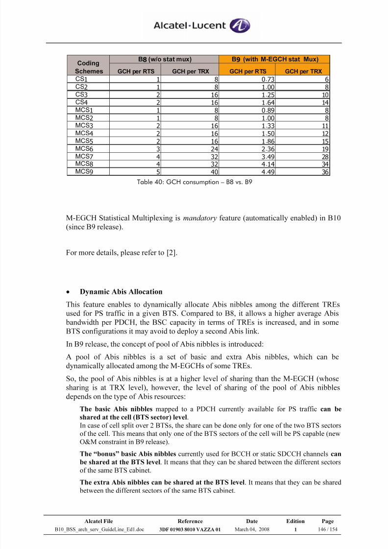
7/21/2019 BSS Architecture Service Guideline B10
http://slidepdf.com/reader/full/bss-architecture-service-guideline-b10 146/154
Alcatel File Reference Date Edition Page
B10_BSS_arch_serv_GuideLine_Ed1.doc 3DF 01903 8010 VAZZA 01 March 04, 2008 1 146 / 154
GCH per RTS GCH per TRX GCH per RTS GCH per TRX
CS1 1 8 0.73 6
CS2 1 8 1.00 8
CS3 2 16 1.25 10CS4 2 16 1.64 14
MCS1 1 8 0.89 8
MCS2 1 8 1.00 8
MCS3 2 16 1.33 11
MCS4 2 16 1.50 12
MCS5 2 16 1.86 15
MCS6 3 24 2.36 19
MCS7 4 32 3.49 28
MCS8 4 32 4.14 34
MCS9 5 40 4.49 36
Coding
Schemes
B8 (w/o stat mux) B9 (with M-EGCH stat Mux)
Table 40: GCH consumption – B8 vs. B9
M-EGCH Statistical Multiplexing is mandatory feature (automatically enabled) in B10
(since B9 release).
For more details, please refer to [2].
• Dynamic Abis Allocation
This feature enables to dynamically allocate Abis nibbles among the different TREs
used for PS traffic in a given BTS. Compared to B8, it allows a higher average Abis
bandwidth per PDCH, the BSC capacity in terms of TREs is increased, and in some
BTS configurations it may avoid to deploy a second Abis link.
In B9 release, the concept of pool of Abis nibbles is introduced:
A pool of Abis nibbles is a set of basic and extra Abis nibbles, which can be
dynamically allocated among the M-EGCHs of some TREs.
So, the pool of Abis nibbles is at a higher level of sharing than the M-EGCH (whose
sharing is at TRX level), however, the level of sharing of the pool of Abis nibblesdepends on the type of Abis resources:
The basic Abis nibbles mapped to a PDCH currently available for PS traffic can be
shared at the cell (BTS sector) level.
In case of cell split over 2 BTSs, the share can be done only for one of the two BTS sectors
of the cell. This means that only one of the BTS sectors of the cell will be PS capable (new
O&M constraint in B9 release).
The “bonus” basic Abis nibbles currently used for BCCH or static SDCCH channels can
be shared at the BTS level. It means that they can be shared between the different sectors
of the same BTS cabinet.
The extra Abis nibbles can be shared at the BTS level. It means that they can be shared between the different sectors of the same BTS cabinet.
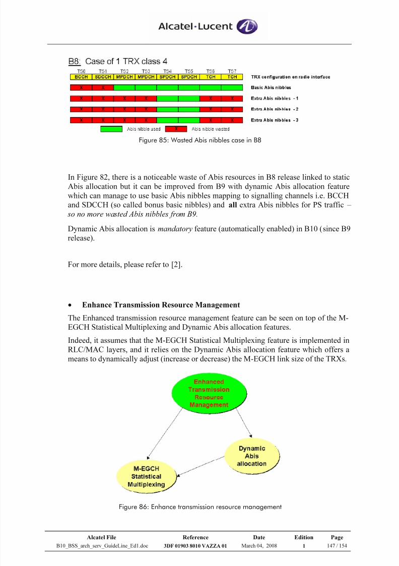
7/21/2019 BSS Architecture Service Guideline B10
http://slidepdf.com/reader/full/bss-architecture-service-guideline-b10 147/154
Alcatel File Reference Date Edition Page
B10_BSS_arch_serv_GuideLine_Ed1.doc 3DF 01903 8010 VAZZA 01 March 04, 2008 1 147 / 154
Figure 85: Wasted Abis nibbles case in B8
In Figure 82, there is a noticeable waste of Abis resources in B8 release linked to static
Abis allocation but it can be improved from B9 with dynamic Abis allocation feature
which can manage to use basic Abis nibbles mapping to signalling channels i.e. BCCHand SDCCH (so called bonus basic nibbles) and all extra Abis nibbles for PS traffic –
so no more wasted Abis nibbles from B9.
Dynamic Abis allocation is mandatory feature (automatically enabled) in B10 (since B9
release).
For more details, please refer to [2].
• Enhance Transmission Resource Management
The Enhanced transmission resource management feature can be seen on top of the M-
EGCH Statistical Multiplexing and Dynamic Abis allocation features.
Indeed, it assumes that the M-EGCH Statistical Multiplexing feature is implemented in
RLC/MAC layers, and it relies on the Dynamic Abis allocation feature which offers a
means to dynamically adjust (increase or decrease) the M-EGCH link size of the TRXs.
Figure 86: Enhance transmission resource management
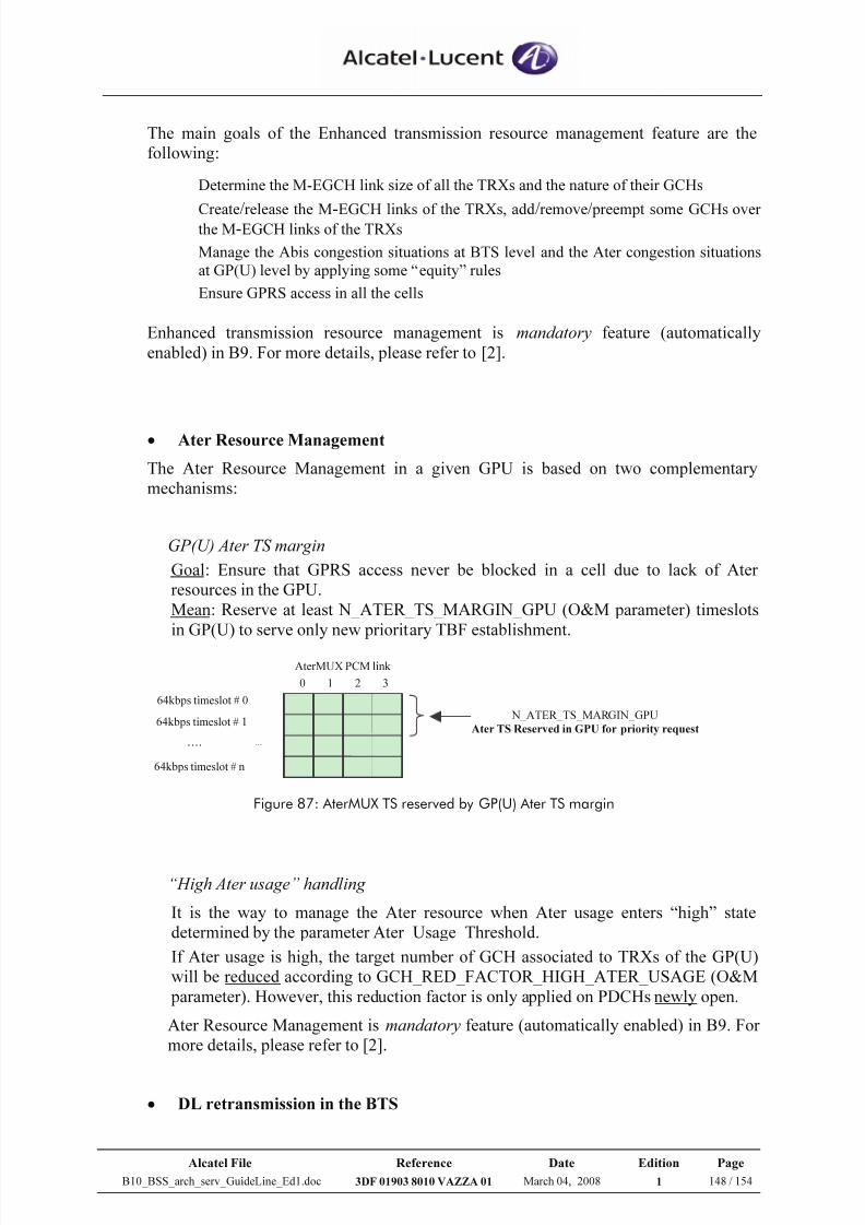
7/21/2019 BSS Architecture Service Guideline B10
http://slidepdf.com/reader/full/bss-architecture-service-guideline-b10 148/154
Alcatel File Reference Date Edition Page
B10_BSS_arch_serv_GuideLine_Ed1.doc 3DF 01903 8010 VAZZA 01 March 04, 2008 1 148 / 154
The main goals of the Enhanced transmission resource management feature are the
following:
Determine the M-EGCH link size of all the TRXs and the nature of their GCHs
Create/release the M-EGCH links of the TRXs, add
/remove
/ preempt some GCHs over
the M-EGCH links of the TRXs
Manage the Abis congestion situations at BTS level and the Ater congestion situations
at GP(U) level by applying some “equity” rules
Ensure GPRS access in all the cells
Enhanced transmission resource management is mandatory feature (automatically
enabled) in B9. For more details, please refer to [2].
• Ater Resource Management
The Ater Resource Management in a given GPU is based on two complementary
mechanisms:
GP(U) Ater TS margin
Goal: Ensure that GPRS access never be blocked in a cell due to lack of Ater
resources in the GPU.
Mean: Reserve at least N_ATER_TS_MARGIN_GPU (O&M parameter) timeslots
in GP(U) to serve only new prioritary TBF establishment.
AterMUX PCM link 64kbps timeslot # 0 64kbps timeslot # 1
…. 64kbps timeslot # n
...
0 1 2 3 N_ATER_TS_MARGIN_GPU
Ater TS Reserved in GPU for priority request
Figure 87: AterMUX TS reserved by GP(U) Ater TS margin
“High Ater usage” handling It is the way to manage the Ater resource when Ater usage enters “high” state
determined by the parameter Ater_Usage_Threshold.
If Ater usage is high, the target number of GCH associated to TRXs of the GP(U)
will be reduced according to GCH_RED_FACTOR_HIGH_ATER_USAGE (O&M
parameter). However, this reduction factor is only applied on PDCHs newly open.
Ater Resource Management is mandatory feature (automatically enabled) in B9. For
more details, please refer to [2].
• DL retransmission in the BTS
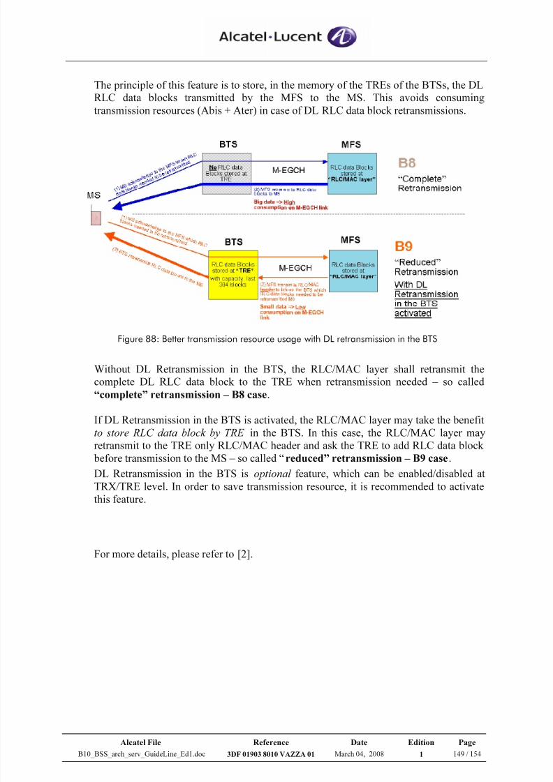
7/21/2019 BSS Architecture Service Guideline B10
http://slidepdf.com/reader/full/bss-architecture-service-guideline-b10 149/154
Alcatel File Reference Date Edition Page
B10_BSS_arch_serv_GuideLine_Ed1.doc 3DF 01903 8010 VAZZA 01 March 04, 2008 1 149 / 154
The principle of this feature is to store, in the memory of the TREs of the BTSs, the DL
RLC data blocks transmitted by the MFS to the MS. This avoids consuming
transmission resources (Abis + Ater) in case of DL RLC data block retransmissions.
Figure 88: Better transmission resource usage with DL retransmission in the BTS
Without DL Retransmission in the BTS, the RLC/MAC layer shall retransmit the
complete DL RLC data block to the TRE when retransmission needed – so called
“complete” retransmission – B8 case.
If DL Retransmission in the BTS is activated, the RLC/MAC layer may take the benefit
to store RLC data block by TRE in the BTS. In this case, the RLC/MAC layer may
retransmit to the TRE only RLC/MAC header and ask the TRE to add RLC data block
before transmission to the MS – so called “reduced” retransmission – B9 case.
DL Retransmission in the BTS is optional feature, which can be enabled/disabled at
TRX/TRE level. In order to save transmission resource, it is recommended to activate
this feature.
For more details, please refer to [2].
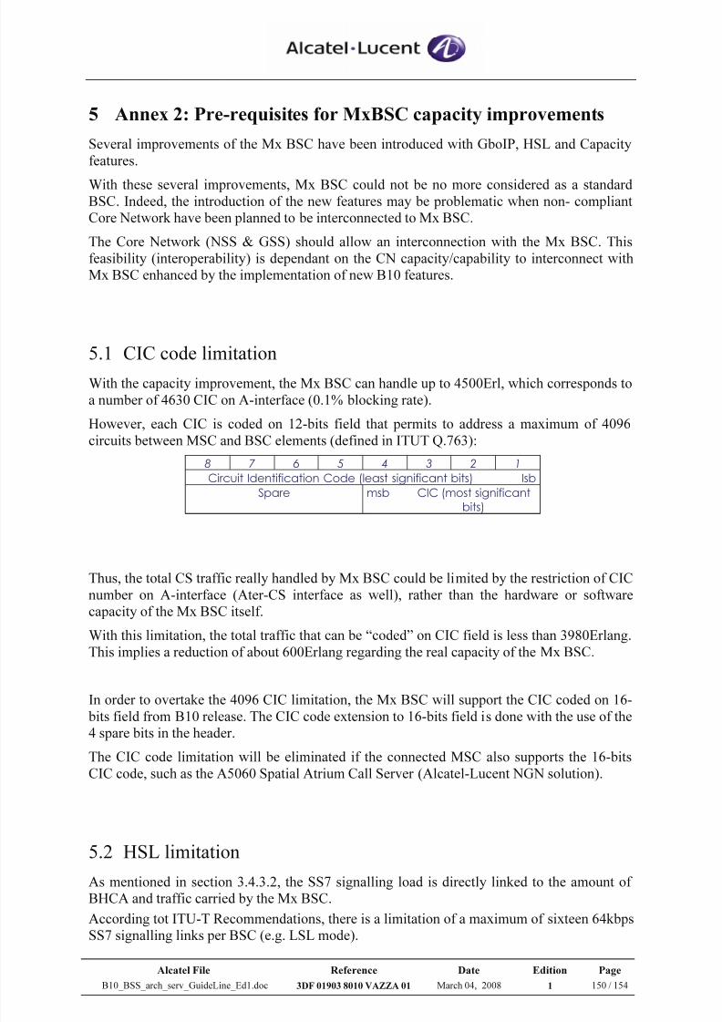
7/21/2019 BSS Architecture Service Guideline B10
http://slidepdf.com/reader/full/bss-architecture-service-guideline-b10 150/154
Alcatel File Reference Date Edition Page
B10_BSS_arch_serv_GuideLine_Ed1.doc 3DF 01903 8010 VAZZA 01 March 04, 2008 1 150 / 154
5 Annex 2: Pre-requisites for MxBSC capacity improvements
Several improvements of the Mx BSC have been introduced with GboIP, HSL and Capacity
features.
With these several improvements, Mx BSC could not be no more considered as a standard
BSC. Indeed, the introduction of the new features may be problematic when non- compliant
Core Network have been planned to be interconnected to Mx BSC.
The Core Network (NSS & GSS) should allow an interconnection with the Mx BSC. This
feasibility (interoperability) is dependant on the CN capacity/capability to interconnect with
Mx BSC enhanced by the implementation of new B10 features.
5.1 CIC code limitationWith the capacity improvement, the Mx BSC can handle up to 4500Erl, which corresponds to
a number of 4630 CIC on A-interface (0.1% blocking rate).
However, each CIC is coded on 12-bits field that permits to address a maximum of 4096
circuits between MSC and BSC elements (defined in ITUT Q.763):
8 7 6 5 4 3 2 1
Circuit Identification Code (least significant bits) Isb
Spare msb CIC (most significant
bits)
Thus, the total CS traffic really handled by Mx BSC could be limited by the restriction of CIC
number on A-interface (Ater-CS interface as well), rather than the hardware or software
capacity of the Mx BSC itself.
With this limitation, the total traffic that can be “coded” on CIC field is less than 3980Erlang.
This implies a reduction of about 600Erlang regarding the real capacity of the Mx BSC.
In order to overtake the 4096 CIC limitation, the Mx BSC will support the CIC coded on 16-
bits field from B10 release. The CIC code extension to 16-bits field is done with the use of the4 spare bits in the header.
The CIC code limitation will be eliminated if the connected MSC also supports the 16-bits
CIC code, such as the A5060 Spatial Atrium Call Server (Alcatel-Lucent NGN solution).
5.2 HSL limitation
As mentioned in section 3.4.3.2, the SS7 signalling load is directly linked to the amount of
BHCA and traffic carried by the Mx BSC.
According tot ITU-T Recommendations, there is a limitation of a maximum of sixteen 64kbps
SS7 signalling links per BSC (e.g. LSL mode).
7/21/2019 BSS Architecture Service Guideline B10
http://slidepdf.com/reader/full/bss-architecture-service-guideline-b10 151/154
Alcatel File Reference Date Edition Page
B10_BSS_arch_serv_GuideLine_Ed1.doc 3DF 01903 8010 VAZZA 01 March 04, 2008 1 151 / 154
This limitation can be reached when the Mx BSC traffic growth occurs.
In order to overtake this limitation, the Alcatel-Lucent solution is to double the signalling
throughput by using HSL functionality (ITU-T Recommendation Q.703 Annex A).
The HSL feature is a mandatory feature in Mx BSC handling traffic higher than 2600Erl (infact 1900Erlang as described in section 3.4.3), and it may be used only if the option is also
supported by the MSC.
At MSC level, the HSL function could be based on two different options;
Two un-channelized 2Mbps PCM links (TS0 + data bulk of 1984kbps)
working in a redundant and load sharing purposes
Two structured 2Mbps PCM links (up to 16 TS per PCM)
The Alcatel-Lucent solution is based on two un-channelized HSL links structured with a
synchronisation TS0 as usual and a data channel of 1984kbps).
To conclude, the CS Core Network that will be interconnected to large Mx BSC (traffic load
higher than 2000Erlang) shall support the un-channelized HSL feature.
For interoperability purposes between Alcatel-Lucent Mx BSC and CS Core Network, the
CSCN elements supporting the HSL feature are:
Legacy MSC equipped with RCP A8362M + Umax EP6
NGN release W4.21
An additional requirement is to be checked; it concerns the signalling mode between BSS and
the MSC.
When MSC supports only the quasi-associated mode of signalling with the BSS, STP
functionality (Signalling Transfer Point) shall be provided outside the BSS (cf. TS 48.006).
5.3 GboIP limitation
As described in sections 2.3.2 & 3.7, the NSE addresses (local IP endpoints) are pre-
established by OMC-R commands (i.e. static) and there is no need for DHCP server to
manage the addresses of IP endpoints.
In that case, the PS Core Network (especially the SGSN element) shall support the static IP
address allocation of the IP endpoints.
While Alcatel-Lucent SGSN use a static IP address allocation (???), most of the third
suppliers’ SGSN are using the automatic IP address management only.
There may be a need for DHCP server in GboIP context (automatic IP addresses instead of O&M through the MFS).
7/21/2019 BSS Architecture Service Guideline B10
http://slidepdf.com/reader/full/bss-architecture-service-guideline-b10 152/154
Alcatel File Reference Date Edition Page
B10_BSS_arch_serv_GuideLine_Ed1.doc 3DF 01903 8010 VAZZA 01 March 04, 2008 1 152 / 154
In addition, the Gb interface type is defined at BSC level allowing the MFS to support mixed-
mode (FR and IP).
Several BSC could be connected to a single SGSN element; there is a strong need regarding
the support of mixed-Gb mode (FR and IP).
For interoperability purposes between Alcatel-Lucent MFS and SGSN, the SGSN will support
mixed Gb mode (FR and IP) and static IP address allocation (SGSN U3.2 & U3.3 roadmap).
As only IPv4 is supported at MFS side, the SGSN shall also support IPv4 protocol.
In the case of GboIP feature, the synchronization clock cannot be extracted from the SGSN.
The following configurations shall be considered:
- In “mixed Gb mode” (FR and IP): clock synchronization can be extracted from the GboFR links
- In GboIP with existing links between MFS & TC: clock synchronization for Ater TDM can beextracted from the TC links
7/21/2019 BSS Architecture Service Guideline B10
http://slidepdf.com/reader/full/bss-architecture-service-guideline-b10 153/154
Alcatel File Reference Date Edition Page
B10_BSS_arch_serv_GuideLine_Ed1.doc 3DF 01903 8010 VAZZA 01 March 04, 2008 1 153 / 154
6 Annex 3: Abis, Ater & Gb over Satellite
Under realization.
7/21/2019 BSS Architecture Service Guideline B10
http://slidepdf.com/reader/full/bss-architecture-service-guideline-b10 154/154
7 Annex 4: Transport migration
7.1 Optimisation over E1
7.2 IP backhauling
Under realization.
END OF DOCUMENT