Embed Size (px)
Citation preview

SCHAKO | Ferdinand Schad KG Phone +49 (0) 7463-980-0 Steigstraße 25-27 Fax +49 (0) 7463-980-200 D-78600 Kolbingen www.SCHAKO.de | [email protected]
Fig.: BSK-RPR with B10 drive USABILITY CERTIFICATES
• Performance Reliability Certificate according to EU-Bau PVO 0761 – CPR – 0245
• EC Certificate of Conformity 0761 – CPD – 0263
• Declaration of Performance DoP-BSK-RPR-2017-08-09
CLASSIFICATION AND STANDARDS
• Classification according to EN 13501-3, depending on the mounting situation EI 90 (ve, ho i↔o) S
• Product standard EN 15650
• Test standard EN 1366-2
PERFORMANCE DATA
• For automatic locking of fire lobbies • For use or connection of a smoke release device
with abZ (e.g. SCHAKO smoke detection system RMS) in connection with suitable release de-vices (e.g. spring return actuator)
SPECIAL FEATURES
• ATEX version available (at an extra charge) • Extensive uses and applications • Housing leakage class C according to EN 1751 • For optimum integration into the building con-
trol system via the SCHAKO EasyBus signalling and switching bus system or the SCHAKO BKSYS fire damper mini-controller
Technical documentation Installation, mounting and operating instructions
BSK-RPR Fire damper
Fire Damper Model BSK-RPR Technical documentation Table of Contents
Construction subject to change. No return possible Version: 2017-08-09 | Page 2
TABLE OF CONTENTS
Table of Contents ........................................................ 2 Description .................................................................. 3 Models and dimensions .............................................. 4 Installation details....................................................... 9 Installation in solid walls ............................................. 9 Installation on solid walls with mounting frame AR . 10 Installation away from solid walls with mounting frame AR ................................................................... 11 Installation in solid ceilings ....................................... 12 Installation on solid ceilings with mounting frame AR .................................................................................. 13 Installation with vertical concrete base on solid ceilings ...................................................................... 14 Installation in lightweight partition walls with metal posts and panelling on both sides ............................ 15 Installation in lightweight partition walls with metal posts and panelling on both sides near the ceiling (solid ceiling) ............................................................. 16 Installation with mounting AR in lightweight partition walls with metal posts and panelling on both sides . 17 Installation close to ceiling (solid ceiling) ................. 18 Installation kit GDL for installation in lightweight partition walls with metal posts and panelling on both sides with sliding ceiling connection ......................... 20 Installation in lightweight partition walls with metal posts and panelling on both sides (F30) ................... 22 Installation close to ceiling (solid ceiling) ................. 23 Installation with mounting AR in lightweight partition walls with metal posts and panelling on both sides (F30) .......................................................................... 24 Installation close to ceiling (solid ceiling) ................. 26 Installation in shaft walls with metal post and panelling on one side. ............................................... 27 Installation close to ceiling (solid ceiling) ................. 28 Installation in shaft walls with metal post and panelling on one side with mounting frame AR ....... 29 Installation close to ceiling (solid ceiling) ................. 30 Installation information ............................................ 31 Technical data ........................................................... 34 Accessories ............................................................... 37 Limit switch ............................................................... 37 Spring return actuators ............................................. 38 Magnets .................................................................... 43 Add-on parts ............................................................. 44 CE marking ................................................................ 47 Order code ................................................................ 48 Specification texts ..................................................... 50 Service ....................................................................... 53 Foreign branch offices .............................................. 58 List of figures/tables/diagrams ................................. 59
Fire Damper Model BSK-RPR Technical documentation
Description
Construction subject to change. No return possible Version: 2017-08-09 | Page 3
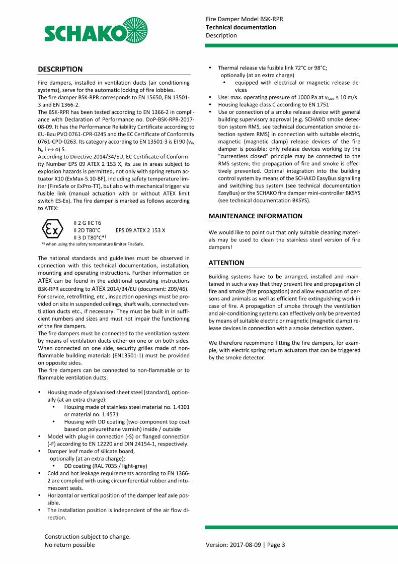
DESCRIPTION
Fire dampers, installed in ventilation ducts (air conditioning systems), serve for the automatic locking of fire lobbies. The fire damper BSK-RPR corresponds to EN 15650, EN 13501-3 and EN 1366-2. The BSK-RPR has been tested according to EN 1366-2 in compli-ance with Declaration of Performance no. DoP-BSK-RPR-2017-08-09. It has the Performance Reliability Certificate according toEU-Bau PVO 0761-CPR-0245 and the EC Certificate of Conformity0761-CPD-0263. Its category according to EN 13501-3 is EI 90 (ve,ho i ↔ o) S.According to Directive 2014/34/EU, EC Certificate of Conform-ity Number EPS 09 ATEX 2 153 X, its use in areas subject toexplosion hazards is permitted, not only with spring return ac-tuator X10 (ExMax-5.10-BF), including safety temperature lim-iter (FireSafe or ExPro-TT), but also with mechanical trigger via fusible link (manual actuation with or without ATEX limitswitch ES-Ex). The fire damper is marked as follows accordingto ATEX:
II 2 G IIC T6 II 2D T80°C II 3 D T80°C*)
EPS 09 ATEX 2 153 X
*) when using the safety temperature limiter FireSafe.
The national standards and guidelines must be observed in connection with this technical documentation, installation, mounting and operating instructions. Further information on ATEX can be found in the additional operating instructions BSK-RPR according to ATEX 2014/34/EU (document: Z09/46). For service, retrofitting, etc., inspection openings must be pro-vided on site in suspended ceilings, shaft walls, connected ven-tilation ducts etc., if necessary. They must be built in in suffi-cient numbers and sizes and must not impair the functioning of the fire dampers. The fire dampers must be connected to the ventilation system by means of ventilation ducts either on one or on both sides. When connected on one side, security grilles made of non-flammable building materials (EN13501-1) must be provided on opposite sides. The fire dampers can be connected to non-flammable or to flammable ventilation ducts.
Housing made of galvanised sheet steel (standard), option-ally (at an extra charge): Housing made of stainless steel material no. 1.4301
or material no. 1.4571 Housing with DD coating (two-component top coat
based on polyurethane varnish) inside / outside Model with plug-in connection (-S) or flanged connection
(-F) according to EN 12220 and DIN 24154-1, respectively. Damper leaf made of silicate board,
optionally (at an extra charge): DD coating (RAL 7035 / light-grey)
Cold and hot leakage requirements according to EN 1366-2 are complied with using circumferential rubber and intu-mescent seals.
Horizontal or vertical position of the damper leaf axle pos-sible.
The installation position is independent of the air flow di-rection.
Thermal release via fusible link 72°C or 98°C; optionally (at an extra charge) equipped with electrical or magnetic release de-
vices Use: max. operating pressure of 1000 Pa at vface ≤ 10 m/s Housing leakage class C according to EN 1751 Use or connection of a smoke release device with general
building supervisory approval (e.g. SCHAKO smoke detec-tion system RMS, see technical documentation smoke de-tection system RMS) in connection with suitable electric, magnetic (magnetic clamp) release devices of the fire damper is possible; only release devices working by the "currentless closed" principle may be connected to the RMS system; the propagation of fire and smoke is effec-tively prevented. Optimal integration into the building control system by means of the SCHAKO EasyBus signalling and switching bus system (see technical documentation EasyBus) or the SCHAKO fire damper mini-controller BKSYS (see technical documentation BKSYS).
MAINTENANCE INFORMATION
We would like to point out that only suitable cleaning materi-als may be used to clean the stainless steel version of fire dampers!
ATTENTION
Building systems have to be arranged, installed and main-tained in such a way that they prevent fire and propagation of fire and smoke (fire propagation) and allow evacuation of per-sons and animals as well as efficient fire extinguishing work in case of fire. A propagation of smoke through the ventilation and air-conditioning systems can effectively only be prevented by means of suitable electric or magnetic (magnetic clamp) re-lease devices in connection with a smoke detection system.
We therefore recommend fitting the fire dampers, for exam-ple, with electric spring return actuators that can be triggered by the smoke detector.
Fire Damper Model BSK-RPR Technical documentation Models and dimensions
Construction subject to change. No return possible Version: 2017-08-09 | Page 4
MODELS AND DIMENSIONS
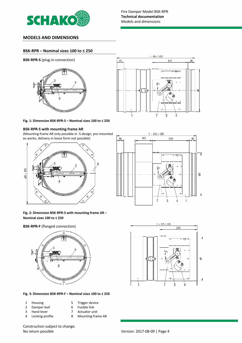
BSK-RPR – Nominal sizes 100 to ≤ 250
BSK-RPR-S (plug-in connection)
Fig. 1: Dimension BSK-RPR-S – Nominal sizes 100 to ≤ 250
BSK-RPR-S with mounting frame AR (Mounting frame AR only possible in -S design, pre-mounted ex works, delivery in loose form not possible)
Fig. 2: Dimension BSK-RPR-S with mounting frame AR – Nominal sizes 100 to ≤ 250
BSK-RPR-F (flanged connection)
Fig. 3: Dimension BSK-RPR-F – Nominal sizes 100 to ≤ 250
1 Housing 5 Trigger device 2 Damper leaf 6 Fusible link 3 Hand lever 7 Actuator unit 4 Locking profile 8 Mounting frame AR
Fire Damper Model BSK-RPR Technical documentation Models and dimensions
Construction subject to change. No return possible Version: 2017-08-09 | Page 5
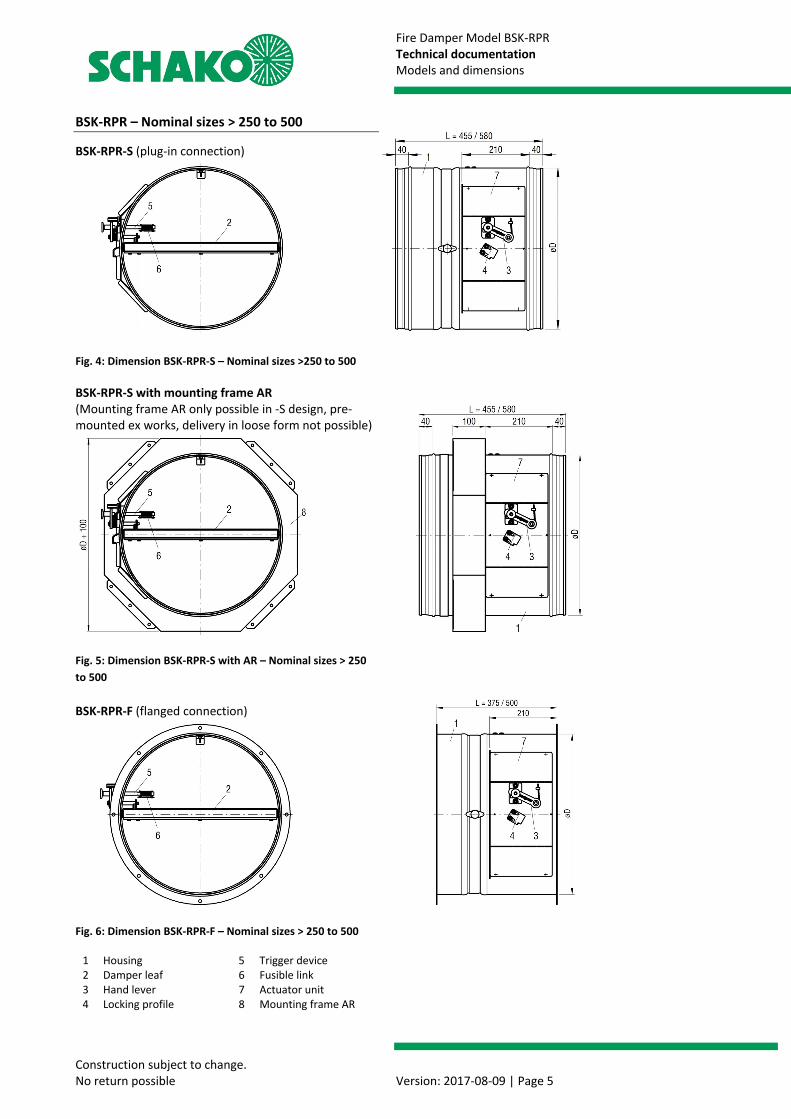
BSK-RPR – Nominal sizes > 250 to 500
BSK-RPR-S (plug-in connection)
Fig. 4: Dimension BSK-RPR-S – Nominal sizes >250 to 500 BSK-RPR-S with mounting frame AR (Mounting frame AR only possible in -S design, pre-mounted ex works, delivery in loose form not possible)
Fig. 5: Dimension BSK-RPR-S with AR – Nominal sizes > 250 to 500 BSK-RPR-F (flanged connection)
Fig. 6: Dimension BSK-RPR-F – Nominal sizes > 250 to 500
1 Housing 5 Trigger device 2 Damper leaf 6 Fusible link 3 Hand lever 7 Actuator unit 4 Locking profile 8 Mounting frame AR

Fire Damper Model BSK-RPR Technical documentation Models and dimensions
Construction subject to change. No return possible Version: 2017-08-09 | Page 6
Available sizes No-mi-nal size
øD [mm]
L [mm]
BSK-RPR-S BSK-RPR-F
100 98 125 123 140 138 160 158 180 178 455 375 200 198 224 222 250 248 280 278 580 500 315 313 (standard) (standard) 355 353 400 398 450 448 500 498
Table 1: Available sizes Rubber lip seal for BSK-RPR-S Model BSK-RPR-S is delivered as standard with a rubber lip seal.
Fig. 7: Rubber lip seal Release devices (pos. 5)
Fig. 8: Release device BSK-RPR
Flange bores BSK-RPR-F
Fig. 9: Flange bores Table to DIN EN 12220 or DIN 24154-1
Nomi-nal size
øD [mm]
øC [mm]
Bolt circle øB
Number of bores
(± 0.5mm) Ø9.5 (± 0.5mm) 100 98 150 132 4 125 123 175 157 4 140 138 190 172 6 160 158 210 192 6 180 178 230 212 6 200 198 250 233 6 224 222 274 257 6 250 248 300 283 6 280 278 340 317 8 315 313 375 352 8 355 353 415 392 8 400 398 460 438 8 450 448 510 488 8 500 498 560 538 8
Table 2: Flange bores SCHAKO ASG-RF / VT-RF / FS-RF: Flange bores suitable for BSK-RPR-F
Fire Damper Model BSK-RPR Technical documentation Models and dimensions
Construction subject to change. No return possible Version: 2017-08-09 | Page 7
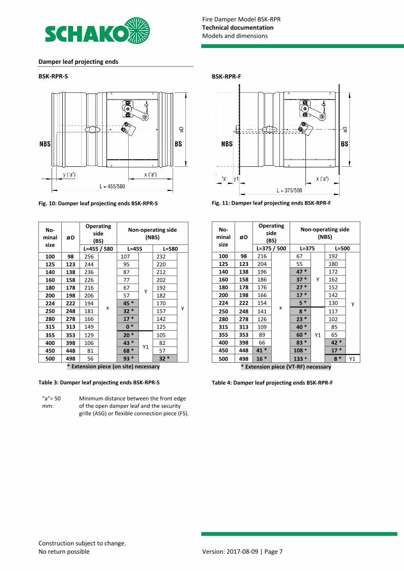
Damper leaf projecting ends
BSK-RPR-S
Fig. 10: Damper leaf projecting ends BSK-RPR-S
No-minal size
øD
Operating side (BS)
Non-operating side (NBS)
L=455 / 580 L=455 L=580 100 98 256
x
107
Y
232
y
125 123 244 95 220 140 138 236 87 212 160 158 226 77 202 180 178 216 67 192 200 198 206 57 182 224 222 194 45 * 170 250 248 181 32 * 157 280 278 166 17 * 142 315 313 149 0 * 125 355 353 129 20 *
Y1
105 400 398 106 43 * 82 450 448 81 68 * 57 500 498 56 93 * 32 *
* Extension piece (on site) necessary Table 3: Damper leaf projecting ends BSK-RPR-S
"a"= 50 mm:
Minimum distance between the front edge of the open damper leaf and the security grille (ASG) or flexible connection piece (FS).
BSK-RPR-F
Fig. 11: Damper leaf projecting ends BSK-RPR-F
No-minal size
øD
Operating side (BS)
Non-operating side (NBS)
L=375 / 500 L=375 L=500 100 98 216
x
67
Y
192
y
125 123 204 55 180 140 138 196 47 * 172 160 158 186 37 * 162 180 178 176 27 * 152 200 198 166 17 * 142 224 222 154 5 * 130 250 248 141 8 *
Y1
117 280 278 126 23 * 102 315 313 109 40 * 85 355 353 89 60 * 65 400 398 66 83 * 42 * 450 448 41 * 108 * 17 * 500 498 16 * 133 * 8 * Y1
* Extension piece (VT-RF) necessary Table 4: Damper leaf projecting ends BSK-RPR-F
Fire Damper Model BSK-RPR Technical documentation Models and dimensions
Construction subject to change. No return possible Version: 2017-08-09 | Page 8
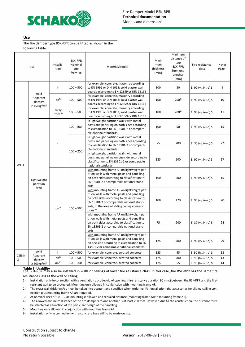
Use The fire damper type BSK-RPR can be fitted as shown in the following table.
Table 5: Usability
Use Installa-tion
BSK-RPR Nominal
size from to
Material/Model
Mini-mum
thickness [mm]
Minimum distance of
two BSK-RPR from one another [mm]
Fire resistance class
Notes Page °
WALL
solid Apparent density
≥ 450kg/m³
in 100 – 500 for example, concrete, masonry according to EN 1996 or DIN 1053; solid plaster wall boards according to EN 12859 or DIN 18163
100 50 EI 90 (ve, i↔o) S 9
on5) 100 – 500 for example, concrete, masonry according to EN 1996 or DIN 1053; solid plaster wall boards according to EN 12859 or DIN 18163
100 2003) EI 90 (ve, i↔o) S 10
away from 1) 100 – 500
for example, concrete, masonry according to EN 1996 or DIN 1053; solid plaster wall boards according to EN 12859 or DIN 18163
100 2004) EI 90 (ve, i↔o) S 11
Lightweight partition
wall
in
100 –500
in lightweight partition walls with metal posts and panelling on both sides according to classification to EN 13501-2 or compara-ble national standards.
100 50 EI 90 (ve, i↔o) S 15
100 – 250
in lightweight partition walls with metal posts and panelling on both sides according to classification to EN 13501-2 or compara-ble national standards.
75 200 EI 30 (ve, i↔o) S 22
in lightweight partition walls with metal posts and panelling on one side according to classification to EN 13501-2 or comparable national standards
125 200 EI 90 (ve, i↔o) S 27
on5) 100 – 500
with mounting frame AR on lightweight par-tition walls with metal posts and panelling on both sides according to classification to EN 13501-2 or comparable national stand-ards
100 200 EI 90 (ve, i↔o) S 15
with mounting frame AR on lightweight par-tition walls with metal posts and panelling on both sides according to classification to EN 13501-2 or comparable national stand-ards, in the area of sliding ceiling connec-tions 2)
100 170 EI 90 (ve, i↔o) S 20
with mounting frame AR on lightweight par-tition walls with metal posts and panelling on both sides according to classification to EN 13501-2 or comparable national stand-ards
75 200 EI 30 (ve, i↔o) S 24
with mounting frame AR on lightweight par-tition walls with metal posts and panelling on one side according to classification to EN 13501-2 or comparable national standards
125 200 EI 90 (ve, i↔o) S 29
CEILING
solid Apparent density
≥ 500kg/m³
in 100 – 500
for example, concrete, aerated concrete
125 55 EI 90 (ho, i↔o) S 12
on5) 100 – 500 for example, concrete, aerated concrete 125 200 EI 90 (ho, i↔o) S 13 on 6) 100 - 500 for example, concrete, aerated concrete 125 55 EI 90 (ho, i↔o) S 14
The BSK-RPR may also be installed in walls or ceilings of lower fire resistance class. In this case, the BSK-RPR has the same fire resistance class as the wall or ceiling. 1) Installation only in connection with a ventilation duct devoid of openings (fire resistance duration 90 min.) between the BSK-RPR and the fire-
resistant wall to be protected. Mounting only allowed in conjunction with mounting frame AR. 2) The exact wall thickness/es must be taken into account and specified when ordering. For installation, the accessories for sliding ceiling con-
nection plus mounting frame AR are required. 3) At nominal sizes of 100 - 250, mounting is allowed at a reduced distance (mounting frame AR to mounting frame AR). 4) The allowed minimum distance of the fire dampers to one another is at least 200 mm. However, due to the construction, the distance must
be selected as a function of the particular design of the panelling. 5) Mounting only allowed in conjunction with mounting frame AR. 6) Installation only in connection with a concrete base still to be made on site.
Fire Damper Model BSK-RPR Technical documentation Installation details
Construction subject to change. No return possible Version: 2017-08-09 | Page 9
General information During mounting or installation, there is a risk of injuries.
To avoid any possible injuries, personal protective equip-ment (PPE) must be worn.
Fire dampers must be installed such that external forces do not impair their permanent functioning. During mount-ing it may be required to provide reinforcements for the housing or the like. The requirement of statically load-bearing lintels may have to be taken into consideration.
Improper transport/handling may result in damage/func-tional impairment. In addition to that, the film of the transport packaging must be removed and the delivery in-spected for completeness.
In storage, fire dampers must be protected from dust, dirt, moisture and the effects of temperature (e.g. direct sun-light, heat-emitting light source, etc.). They must not be exposed to direct effects of the weather and must not be stored below -40 °C or above 50 °C.
The fire damper must be protected from dirt and damage. After installation is complete, any dirt must be removed immediately.
Enough space must be provided for installation, mortar lin-ing, etc.
Carry out a functional check of the fire damper before and after mounting and ensure ready access.
Electrical installations or work on electrical components may only be carried out by skilled electricians. The supply voltage must be switched off when performing this work and secured against being switched on again.
INSTALLATION DETAILS
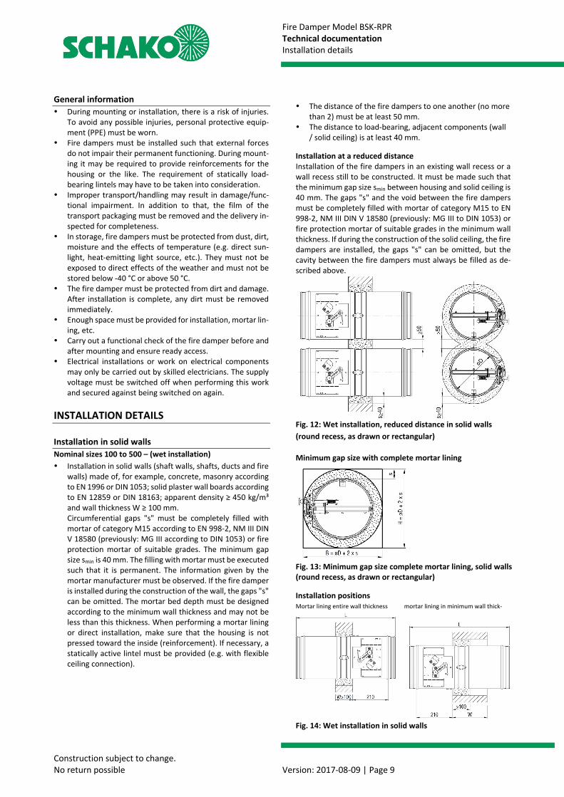
Installation in solid walls Nominal sizes 100 to 500 – (wet installation) Installation in solid walls (shaft walls, shafts, ducts and fire
walls) made of, for example, concrete, masonry according to EN 1996 or DIN 1053; solid plaster wall boards according to EN 12859 or DIN 18163; apparent density ≥ 450 kg/m³ and wall thickness W ≥ 100 mm. Circumferential gaps "s" must be completely filled with mortar of category M15 according to EN 998-2, NM III DIN V 18580 (previously: MG III according to DIN 1053) or fire protection mortar of suitable grades. The minimum gap size smin is 40 mm. The filling with mortar must be executed such that it is permanent. The information given by the mortar manufacturer must be observed. If the fire damper is installed during the construction of the wall, the gaps "s" can be omitted. The mortar bed depth must be designed according to the minimum wall thickness and may not be less than this thickness. When performing a mortar lining or direct installation, make sure that the housing is not pressed toward the inside (reinforcement). If necessary, a statically active lintel must be provided (e.g. with flexible ceiling connection).
The distance of the fire dampers to one another (no more than 2) must be at least 50 mm.
The distance to load-bearing, adjacent components (wall / solid ceiling) is at least 40 mm.
Installation at a reduced distance Installation of the fire dampers in an existing wall recess or a wall recess still to be constructed. It must be made such that the minimum gap size smin between housing and solid ceiling is 40 mm. The gaps "s" and the void between the fire dampers must be completely filled with mortar of category M15 to EN 998-2, NM III DIN V 18580 (previously: MG III to DIN 1053) or fire protection mortar of suitable grades in the minimum wall thickness. If during the construction of the solid ceiling, the fire dampers are installed, the gaps "s" can be omitted, but the cavity between the fire dampers must always be filled as de-scribed above.
Fig. 12: Wet installation, reduced distance in solid walls (round recess, as drawn or rectangular)
Minimum gap size with complete mortar lining
Fig. 13: Minimum gap size complete mortar lining, solid walls (round recess, as drawn or rectangular) Installation positions Mortar lining entire wall thickness mortar lining in minimum wall thick-ness
Fig. 14: Wet installation in solid walls
Fire Damper Model BSK-RPR Technical documentation Installation details
Construction subject to change. No return possible Version: 2017-08-09 | Page 10
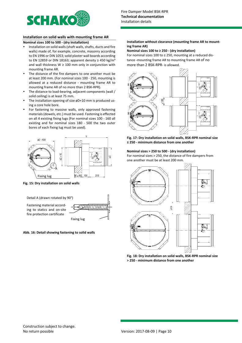
Installation on solid walls with mounting frame AR Nominal sizes 100 to 500 - (dry installation) Installation on solid walls (shaft walls, shafts, ducts and fire
walls) made of, for example, concrete, masonry according to EN 1996 or DIN 1053; solid plaster wall boards according to EN 12859 or DIN 18163; apparent density ≥ 450 kg/m³ and wall thickness W ≥ 100 mm only in conjunction with mounting frame AR.
The distance of the fire dampers to one another must be at least 200 mm. (For nominal sizes 100 - 250, mounting is allowed at a reduced distance - mounting frame AR to mounting frame AR of no more than 2 BSK-RPR).
The distance to load-bearing, adjacent components (wall / solid ceiling) is at least 75 mm.
The installation opening of size øD+10 mm is produced us-ing a core hole bore.
For fastening to massive walls, only approved fastening materials (dowels, etc.) must be used. Fastening is effected on all 4 existing fixing lugs (For nominal sizes 100 - 160 all existing and for nominal sizes 180 - 500 the two outer bores of each fixing lug must be used).
Fig. 15: Dry installation on solid walls Abb. 16: Detail showing fastening to solid walls
Installation without clearance (mounting frame AR to mount-ing frame AR) Nominal sizes 100 to ≥ 250 - (dry installation) For nominal sizes 100 to ≤ 250, mounting at a reduced dis-tance -mounting frame AR to mounting frame AR of no more than 2 BSK-RPR- is allowed.
Fig. 17: Dry installation on solid walls, BSK-RPR nominal size ≤ 250 - minimum distance from one another Nominal sizes > 250 to 500 - (dry installation) For nominal sizes > 250, the distance of fire dampers from one another must be at least 200 mm.
Fig. 18: Dry installation on solid walls, BSK-RPR nominal size > 250 - minimum distance from one another
Fixing lug
Fastening material accord-ing to statics and on-site fire protection certificate
Fixing lug
Detail A (drawn rotated by 90°)
A
Fire Damper Model BSK-RPR Technical documentation Installation details
Construction subject to change. No return possible Version: 2017-08-09 | Page 11
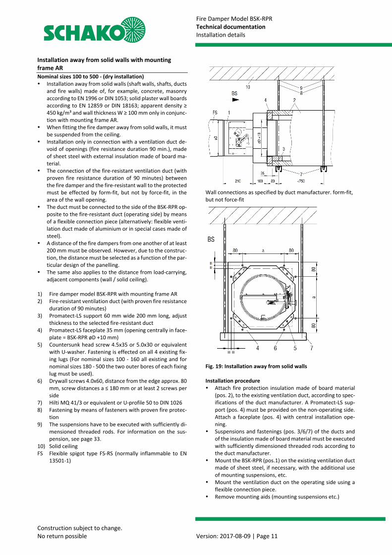
Installation away from solid walls with mounting frame AR Nominal sizes 100 to 500 - (dry installation) Installation away from solid walls (shaft walls, shafts, ducts
and fire walls) made of, for example, concrete, masonry according to EN 1996 or DIN 1053; solid plaster wall boards according to EN 12859 or DIN 18163; apparent density ≥ 450 kg/m³ and wall thickness W ≥ 100 mm only in conjunc-tion with mounting frame AR.
When fitting the fire damper away from solid walls, it must be suspended from the ceiling.
Installation only in connection with a ventilation duct de-void of openings (fire resistance duration 90 min.), made of sheet steel with external insulation made of board ma-terial.
The connection of the fire-resistant ventilation duct (with proven fire resistance duration of 90 minutes) between the fire damper and the fire-resistant wall to the protected must be effected by form-fit, but not by force-fit, in the area of the wall opening.
The duct must be connected to the side of the BSK-RPR op-posite to the fire-resistant duct (operating side) by means of a flexible connection piece (alternatively: flexible venti-lation duct made of aluminium or in special cases made of steel).
A distance of the fire dampers from one another of at least 200 mm must be observed. However, due to the construc-tion, the distance must be selected as a function of the par-ticular design of the panelling.
The same also applies to the distance from load-carrying, adjacent components (wall / solid ceiling).
1) Fire damper model BSK-RPR with mounting frame AR 2) Fire-resistant ventilation duct (with proven fire resistance
duration of 90 minutes) 3) Promatect-LS support 60 mm wide 200 mm long, adjust
thickness to the selected fire-resistant duct 4) Promatect-LS faceplate 35 mm (opening centrally in face-
plate = BSK-RPR øD +10 mm) 5) Countersunk head screw 4.5x35 or 5.0x30 or equivalent
with U-washer. Fastening is effected on all 4 existing fix-ing lugs (For nominal sizes 100 - 160 all existing and for nominal sizes 180 - 500 the two outer bores of each fixing lug must be used).
6) Drywall screws 4.0x60, distance from the edge approx. 80 mm, screw distances a ≤ 180 mm or at least 2 screws per side
7) Hilti MQ 41/3 or equivalent or U-profile 50 to DIN 1026 8) Fastening by means of fasteners with proven fire protec-
tion 9) The suspensions have to be executed with sufficiently di-
mensioned threaded rods. For information on the sus-pension, see page 33.
10) Solid ceiling FS Flexible spigot type FS-RS (normally inflammable to EN
13501-1)
Wall connections as specified by duct manufacturer. form-fit, but not force-fit Fig. 19: Installation away from solid walls Installation procedure Attach fire protection insulation made of board material
(pos. 2), to the existing ventilation duct, according to spec-ifications of the duct manufacturer. A Promatect-LS sup-port (pos. 4) must be provided on the non-operating side. Attach a faceplate (pos. 4) with central installation ope-ning.
Suspensions and fastenings (pos. 3/6/7) of the ducts and of the insulation made of board material must be executed with sufficiently dimensioned threaded rods according to the duct manufacturer.
Mount the BSK-RPR (pos.1) on the existing ventilation duct made of sheet steel, if necessary, with the additional use of mounting suspensions, etc.
Mount the ventilation duct on the operating side using a flexible connection piece.
Remove mounting aids (mounting suspensions etc.)
Fire Damper Model BSK-RPR Technical documentation Installation details
Construction subject to change. No return possible Version: 2017-08-09 | Page 12
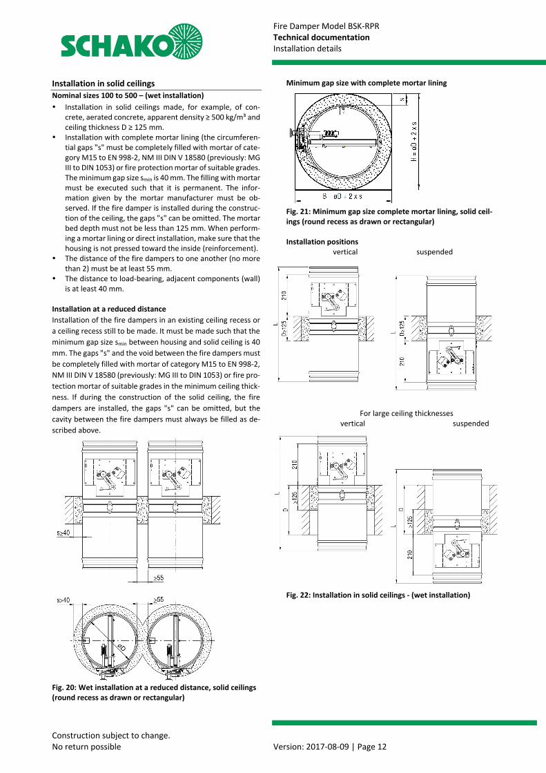
Installation in solid ceilings Nominal sizes 100 to 500 – (wet installation) Installation in solid ceilings made, for example, of con-
crete, aerated concrete, apparent density ≥ 500 kg/m³ and ceiling thickness D ≥ 125 mm.
Installation with complete mortar lining (the circumferen-tial gaps "s" must be completely filled with mortar of cate-gory M15 to EN 998-2, NM III DIN V 18580 (previously: MG III to DIN 1053) or fire protection mortar of suitable grades. The minimum gap size smin is 40 mm. The filling with mortar must be executed such that it is permanent. The infor-mation given by the mortar manufacturer must be ob-served. If the fire damper is installed during the construc-tion of the ceiling, the gaps "s" can be omitted. The mortar bed depth must not be less than 125 mm. When perform-ing a mortar lining or direct installation, make sure that the housing is not pressed toward the inside (reinforcement).
The distance of the fire dampers to one another (no more than 2) must be at least 55 mm.
The distance to load-bearing, adjacent components (wall) is at least 40 mm.
Installation at a reduced distance Installation of the fire dampers in an existing ceiling recess or a ceiling recess still to be made. It must be made such that the minimum gap size smin between housing and solid ceiling is 40 mm. The gaps "s" and the void between the fire dampers must be completely filled with mortar of category M15 to EN 998-2, NM III DIN V 18580 (previously: MG III to DIN 1053) or fire pro-tection mortar of suitable grades in the minimum ceiling thick-ness. If during the construction of the solid ceiling, the fire dampers are installed, the gaps "s" can be omitted, but the cavity between the fire dampers must always be filled as de-scribed above.
Fig. 20: Wet installation at a reduced distance, solid ceilings (round recess as drawn or rectangular)
Minimum gap size with complete mortar lining
Fig. 21: Minimum gap size complete mortar lining, solid ceil-ings (round recess as drawn or rectangular) Installation positions vertical suspended
For large ceiling thicknesses vertical suspended
Fig. 22: Installation in solid ceilings - (wet installation)
Fire Damper Model BSK-RPR Technical documentation Installation details
Construction subject to change. No return possible Version: 2017-08-09 | Page 13
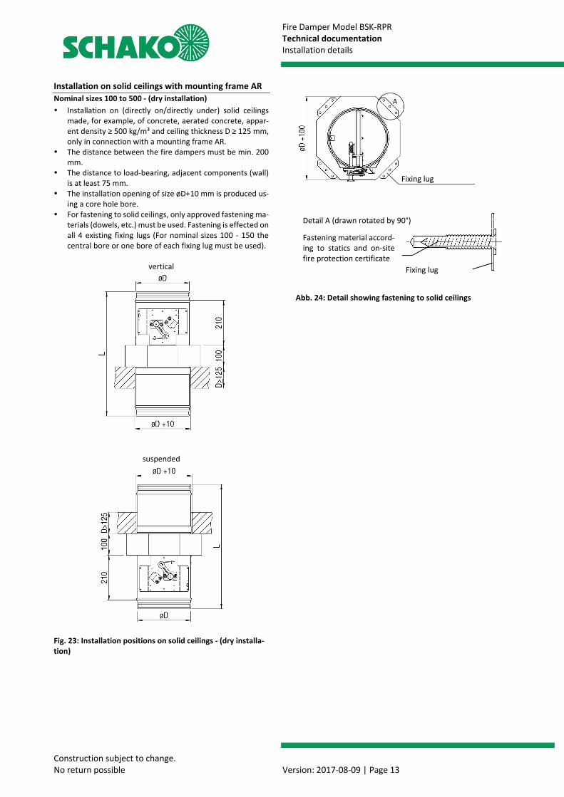
Installation on solid ceilings with mounting frame AR Nominal sizes 100 to 500 - (dry installation) Installation on (directly on/directly under) solid ceilings
made, for example, of concrete, aerated concrete, appar-ent density ≥ 500 kg/m³ and ceiling thickness D ≥ 125 mm, only in connection with a mounting frame AR.
The distance between the fire dampers must be min. 200 mm.
The distance to load-bearing, adjacent components (wall) is at least 75 mm.
The installation opening of size øD+10 mm is produced us-ing a core hole bore.
For fastening to solid ceilings, only approved fastening ma-terials (dowels, etc.) must be used. Fastening is effected on all 4 existing fixing lugs (For nominal sizes 100 - 150 the central bore or one bore of each fixing lug must be used).
vertical
suspended
Fig. 23: Installation positions on solid ceilings - (dry installa-tion)
Abb. 24: Detail showing fastening to solid ceilings
Fastening material accord-ing to statics and on-site fire protection certificate
Fixing lug
Detail A (drawn rotated by 90°)
Fixing lug
A
Fire Damper Model BSK-RPR Technical documentation Installation details
Construction subject to change. No return possible Version: 2017-08-09 | Page 14
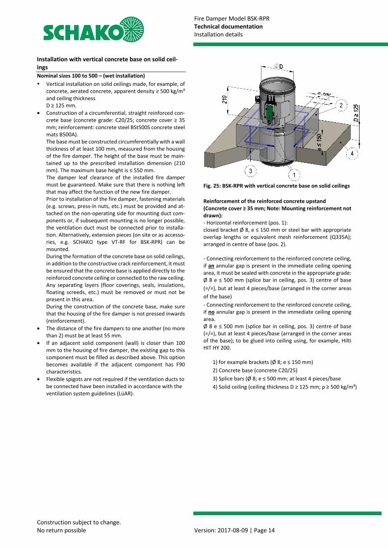
Installation with vertical concrete base on solid ceil-ings Nominal sizes 100 to 500 – (wet installation) Vertical installation on solid ceilings made, for example, of
concrete, aerated concrete, apparent density ≥ 500 kg/m³ and ceiling thickness D ≥ 125 mm.
• Construction of a circumferential, straight reinforced con-crete base (concrete grade: C20/25; concrete cover ≥ 35 mm; reinforcement: concrete steel BSt500S concrete steel mats B500A). The base must be constructed circumferentially with a wall thickness of at least 100 mm, measured from the housing of the fire damper. The height of the base must be main-tained up to the prescribed installation dimension (210 mm). The maximum base height is ≤ 550 mm. The damper leaf clearance of the installed fire damper must be guaranteed. Make sure that there is nothing left that may affect the function of the new fire damper. Prior to installation of the fire damper, fastening materials (e.g. screws, press-in nuts, etc.) must be provided and at-tached on the non-operating side for mounting duct com-ponents or, if subsequent mounting is no longer possible, the ventilation duct must be connected prior to installa-tion. Alternatively, extension pieces (on site or as accesso-ries, e.g. SCHAKO type VT-RF for BSK-RPR) can be mounted. During the formation of the concrete base on solid ceilings, in addition to the constructive crack reinforcement, it must be ensured that the concrete base is applied directly to the reinforced concrete ceiling or connected to the raw ceiling. Any separating layers (floor coverings, seals, insulations, floating screeds, etc.) must be removed or must not be present in this area. During the construction of the concrete base, make sure that the housing of the fire damper is not pressed inwards (reinforcement).
• The distance of the fire dampers to one another (no more than 2) must be at least 55 mm.
• If an adjacent solid component (wall) is closer than 100 mm to the housing of fire damper, the existing gap to this component must be filled as described above. This option becomes available if the adjacent component has F90 characteristics.
• Flexible spigots are not required if the ventilation ducts to be connected have been installed in accordance with the ventilation system guidelines (LüAR).
Fig. 25: BSK-RPR with vertical concrete base on solid ceilings Reinforcement of the reinforced concrete upstand (Concrete cover ≥ 35 mm; Note: Mounting reinforcement not drawn): - Horizontal reinforcement (pos. 1): closed bracket Ø 8, e ≤ 150 mm or steel bar with appropriate overlap lengths or equivalent mesh reinforcement (Q335A); arranged in centre of base (pos. 2). - Connecting reinforcement to the reinforced concrete ceiling, if an annular gap is present in the immediate ceiling opening area, it must be sealed with concrete in the appropriate grade: Ø 8 e ≤ 500 mm (splice bar in ceiling, pos. 3) centre of base (=/=), but at least 4 pieces/base (arranged in the corner areas of the base) - Connecting reinforcement to the reinforced concrete ceiling, if no annular gap is present in the immediate ceiling opening area. Ø 8 e ≤ 500 mm (splice bar in ceiling, pos. 3) centre of base (=/=), but at least 4 pieces/base (arranged in the corner areas of the base); to be glued into ceiling using, for example, Hilti HIT HY 200.
1) for example brackets (Ø 8; e ≤ 150 mm) 2) Concrete base (concrete C20/25) 3) Splice bars (Ø 8; e ≤ 500 mm; at least 4 pieces/base 4) Solid ceiling (ceiling thickness D ≥ 125 mm; ρ ≥ 500 kg/m³)

Fire Damper Model BSK-RPR Technical documentation Installation details
Construction subject to change. No return possible Version: 2017-08-09 | Page 15
Installation in lightweight partition walls with metal posts and panelling on both sides Nominal sizes 100 to 500 – (wet installation) Installation in lightweight partition walls with metal posts
and panelling on both sides (gypsum-bonded wall boards; wall thickness ≥ 100 mm) according to classification to EN 13501-2 or comparable national standards.
Use of flexible connection pieces required on both sides (alternatively: flexible ventilation duct made of aluminium)
No additional, permanent suspensions or attachments of the BSK-RPR are allowed, and installation and mounting aids must be removed.
Mortar lining: circumferential gaps must be completely filled with mortar of category M15 to EN 998-2, NM II DIN V 18580 (previously: MG III to DIN 1053) or fire protection mortar of suitable grades. The gap dimension is approx. 40 mm (housing / reveal). The mortar bed depth must not be less than 100 mm. For mortar lining, make sure that the housing is not pressed inwards (reinforcement).
The distance of the fire dampers to one another (no more than 2) must be at least 50 mm.
The distance from load-carrying, adjacent components is, due to the construction, at least 105 mm from the wall and at least 95 mm from the solid ceiling. The actual minimum distance may slightly differ from the distances mentioned above and must be executed and adapted as a function of the wall connection type.
Mounting information: In the overlap area of the exchangeable profiles, they must be riveted, crimped or screwed once on both sides. These connec-tions are only for fastening the individual metal profiles during mounting.
Fig. 26: Metal posts plus required exchange parts for BSK-RPR at a reduced distance (wet installation)
Fig. 27: Wet installation in lightweight partition wall
Installation sequence: Mount the metal posts and the wall in accordance with the
specifications of the wall manufacturer and the required exchange parts as shown on Fig. 26. Take into account cir-cumferential lining of the reveals with plasterboards (12.5 mm).
Insert the BSK-RPR into the wall recess (operating side - observe the installation dimension of 210 mm). Average out the circumferential annular gap evenly between the wall and the BSK-RPR. Mount the BSK-RPR with the help of mounting suspensions, etc.
Insert mortar (pos. 9) into the circumferential gap 40 mm in width between the housing of the BSK-RPR and the wall recess.
After the mortar has set, the mounting aids (mounting sus-pensions, etc.) must be removed.
Fire Damper Model BSK-RPR Technical documentation Installation details
Construction subject to change. No return possible Version: 2017-08-09 | Page 16
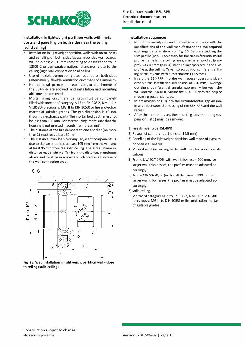
Installation in lightweight partition walls with metal posts and panelling on both sides near the ceiling (solid ceiling) Installation in lightweight partition walls with metal posts
and panelling on both sides (gypsum-bonded wall boards; wall thickness ≥ 100 mm) according to classification to EN 13501-2 or comparable national standards, close to the ceiling (rigid wall connection solid ceiling).
Use of flexible connection pieces required on both sides (alternatively: flexible ventilation duct made of aluminium)
No additional, permanent suspensions or attachments of the BSK-RPR are allowed, and installation and mounting aids must be removed.
Mortar lining: circumferential gaps must be completely filled with mortar of category M15 to EN 998-2, NM II DIN V 18580 (previously: MG III to DIN 1053) or fire protection mortar of suitable grades. The gap dimension is 40 mm (housing / exchange part). The mortar bed depth must not be less than 100 mm. For mortar lining, make sure that the housing is not pressed inwards (reinforcement).
The distance of the fire dampers to one another (no more than 2) must be at least 50 mm.
The distance from load-carrying, adjacent components is, due to the construction, at least 105 mm from the wall and at least 95 mm from the solid ceiling. The actual minimum distance may slightly differ from the distances mentioned above and must be executed and adapted as a function of the wall connection type.
Fig. 28: Wet installation in lightweight partition wall - close to ceiling (solid ceiling)
Installation sequence: Mount the metal posts and the wall in accordance with the
specifications of the wall manufacturer and the required exchange parts as shown on Fig. 26. Before attaching the UW-profile (pos. 5) necessary for the circumferential metal profile frame in the ceiling area, a mineral wool strip ap-prox 50 x 40 mm (pos. 4) must be incorporated in the UW-profile at the ceiling. Take into account circumferential lin-ing of the reveals with plasterboards (12.5 mm).
Insert the BSK-RPR into the wall recess (operating side - observe the installation dimension of 210 mm). Average out the circumferential annular gap evenly between the wall and the BSK-RPR. Mount the BSK-RPR with the help of mounting suspensions, etc.
Insert mortar (pos. 9) into the circumferential gap 40 mm in width between the housing of the BSK-RPR and the wall recess.
After the mortar has set, the mounting aids (mounting sus-pensions, etc.) must be removed.
1) Fire damper type BSK-RPR 2) Reveal, circumferential (-on site- 12.5-mm) 3) Panelling of the lightweight partition wall made of gypsum-
bonded wall boards 4) Mineral wool (according to the wall manufacturer's specifi-
cations) 5) Profile UW 50/40/06 (with wall thickness = 100 mm, for
larger wall thicknesses, the profiles must be adapted ac-cordingly).
6) Profile CW 50/50/06 (with wall thickness = 100 mm, for larger wall thicknesses, the profiles must be adapted ac-cordingly).
7) Solid ceiling 9) Mortar of category M15 to EN 998-2, NM II DIN V 18580
(previously: MG III to DIN 1053) or fire protection mortar of suitable grades.
Fire Damper Model BSK-RPR Technical documentation Installation details
Construction subject to change. No return possible Version: 2017-08-09 | Page 17
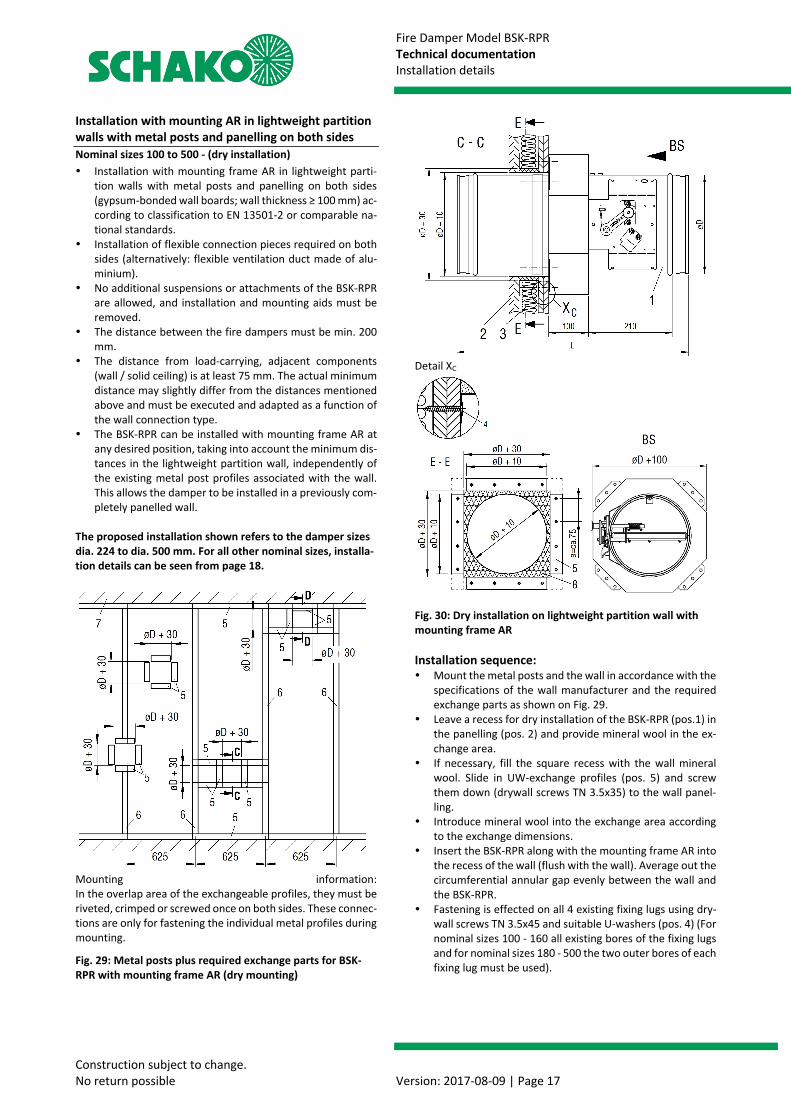
Installation with mounting AR in lightweight partition walls with metal posts and panelling on both sides Nominal sizes 100 to 500 - (dry installation) Installation with mounting frame AR in lightweight parti-
tion walls with metal posts and panelling on both sides (gypsum-bonded wall boards; wall thickness ≥ 100 mm) ac-cording to classification to EN 13501-2 or comparable na-tional standards.
Installation of flexible connection pieces required on both sides (alternatively: flexible ventilation duct made of alu-minium).
No additional suspensions or attachments of the BSK-RPR are allowed, and installation and mounting aids must be removed.
The distance between the fire dampers must be min. 200 mm.
The distance from load-carrying, adjacent components (wall / solid ceiling) is at least 75 mm. The actual minimum distance may slightly differ from the distances mentioned above and must be executed and adapted as a function of the wall connection type.
The BSK-RPR can be installed with mounting frame AR at any desired position, taking into account the minimum dis-tances in the lightweight partition wall, independently of the existing metal post profiles associated with the wall. This allows the damper to be installed in a previously com-pletely panelled wall.
The proposed installation shown refers to the damper sizes dia. 224 to dia. 500 mm. For all other nominal sizes, installa-tion details can be seen from page 18.
Mounting information: In the overlap area of the exchangeable profiles, they must be riveted, crimped or screwed once on both sides. These connec-tions are only for fastening the individual metal profiles during mounting.
Fig. 29: Metal posts plus required exchange parts for BSK-RPR with mounting frame AR (dry mounting)
Detail XC
Fig. 30: Dry installation on lightweight partition wall with mounting frame AR Installation sequence: Mount the metal posts and the wall in accordance with the
specifications of the wall manufacturer and the required exchange parts as shown on Fig. 29.
Leave a recess for dry installation of the BSK-RPR (pos.1) in the panelling (pos. 2) and provide mineral wool in the ex-change area.
If necessary, fill the square recess with the wall mineral wool. Slide in UW-exchange profiles (pos. 5) and screw them down (drywall screws TN 3.5x35) to the wall panel-ling.
Introduce mineral wool into the exchange area according to the exchange dimensions.
Insert the BSK-RPR along with the mounting frame AR into the recess of the wall (flush with the wall). Average out the circumferential annular gap evenly between the wall and the BSK-RPR.
Fastening is effected on all 4 existing fixing lugs using dry-wall screws TN 3.5x45 and suitable U-washers (pos. 4) (For nominal sizes 100 - 160 all existing bores of the fixing lugs and for nominal sizes 180 - 500 the two outer bores of each fixing lug must be used).
Fire Damper Model BSK-RPR Technical documentation Installation details
Construction subject to change. No return possible Version: 2017-08-09 | Page 18
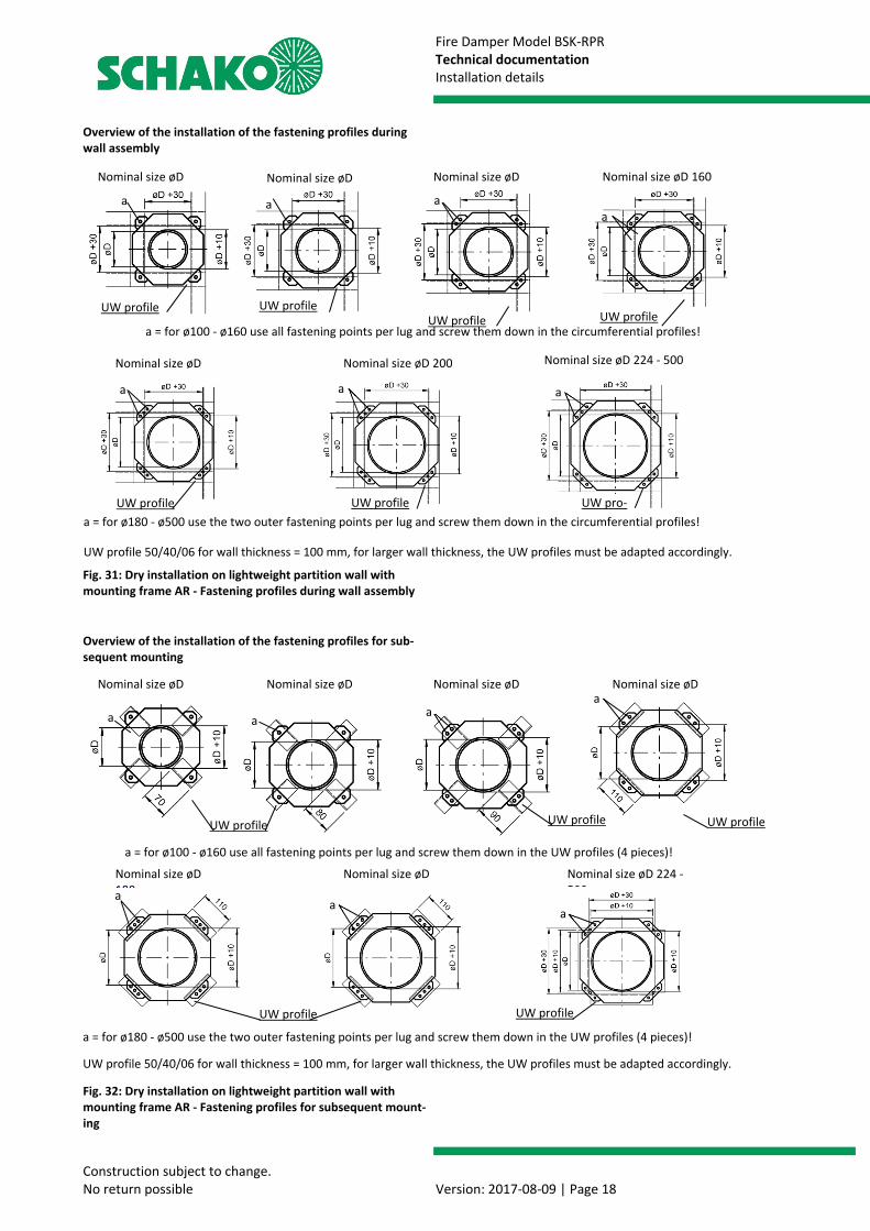
Overview of the installation of the fastening profiles during wall assembly
Fig. 31: Dry installation on lightweight partition wall with mounting frame AR - Fastening profiles during wall assembly
Overview of the installation of the fastening profiles for sub-sequent mounting
Fig. 32: Dry installation on lightweight partition wall with mounting frame AR - Fastening profiles for subsequent mount-ing
a = for ø180 - ø500 use the two outer fastening points per lug and screw them down in the circumferential profiles!
Nominal size øD 160
a = for ø180 - ø500 use the two outer fastening points per lug and screw them down in the UW profiles (4 pieces)!
Nominal size øD 224 - 500
Nominal size øD Nominal size øD Nominal size øD
UW profile UW profileUW profile
UW profile 50/40/06 for wall thickness = 100 mm, for larger wall thickness, the UW profiles must be adapted accordingly.
UW profile
a = for ø100 - ø160 use all fastening points per lug and screw them down in the circumferential profiles!
Nominal size øD Nominal size øD 200
Nominal size øD Nominal size øD Nominal size øD Nominal size øD
UW profile
a = for ø100 - ø160 use all fastening points per lug and screw them down in the UW profiles (4 pieces)!
UW profile
aa
UW profile
a
Nominal size øD 180
Nominal size øD
a a
Nominal size øD 224 - 500
a
UW profile 50/40/06 for wall thickness = 100 mm, for larger wall thickness, the UW profiles must be adapted accordingly.
a
UW profile UW profile
UW pro-UW profile
aa
UW profile
a
a a aa

Fire Damper Model BSK-RPR Technical documentation Installation details
Construction subject to change. No return possible Version: 2017-08-09 | Page 19
Installation close to ceiling (solid ceiling) Installation with mounting frame AR in lightweight parti-
tion walls with metal posts and panelling on both sides (gypsum-bonded wall boards; wall thickness ≥ 100 mm) ac-cording to classification to EN 13501-2 or comparable na-tional standards.
Installation of flexible connection pieces required on both sides (alternatively: flexible ventilation duct made of alu-minium).
No additional suspensions or attachments of the BSK-RPR are allowed, and installation and mounting aids must be removed.
Installation directly under the solid ceiling must be carried out during assembly of the wall and does not constitute a sliding ceiling connection, but requires additional accesso-ries.
The distance between the fire dampers must be min. 200 mm.
The distance from load-carrying, adjacent components (wall / solid ceiling) is at least 75 mm. The actual minimum distance may slightly differ from the distances mentioned above and must be executed and adapted as a function of the wall connection type.
The BSK-RPR can be installed with mounting frame AR at any desired position, taking into account the minimum dis-tances in the lightweight partition wall, independently of the existing metal post profiles associated with the wall. This allows the damper to be installed in a previously com-pletely panelled wall.
The proposed installation shown refers to the damper sizes dia. 224 to dia. 500 mm. For all other nominal sizes, installa-tion details can be seen from page 18.
Fig. 33: Dry installation on lightweight partition wall with mounting frame AR directly under the solid ceiling
Installation sequence: Mount the metal posts and the wall in accordance with the
specifications of the wall manufacturer and the required exchange parts as shown on Fig. 29.
Leave a recess for dry installation of the BSK-RPR (pos.1) in the panelling (pos. 2) and provide mineral wool in the ex-change area.
If necessary, fill the square recess with the wall mineral wool. Slide in UW-exchange profiles (pos. 5) and screw them down (drywall screws TN 3.5x35) to the wall panel-ling.
Introduce mineral wool into the exchange area according to the exchange dimensions.
Insert the BSK-RPR along with the mounting frame AR into the recess of the wall (flush with the wall). Average out the circumferential annular gap evenly between the wall and the BSK-RPR.
Fastening is effected on all 4 existing fixing lugs using dry-wall screws TN 3.5x45 and suitable U-washers (pos. 4) (For nominal sizes 100 - 160 all existing bores of the fixing lugs and for nominal sizes 180 - 500 the two outer bores of each fixing lug must be used).
1) Fire damper model BSK-RPR with mounting frame AR 2) Panelling of the lightweight partition wall made of gyp-
sum-bonded wall boards 3) Mineral wool (according to the wall manufacturer's spec-
ifications) 4) Drywall screws TN 3.5x45 and suitable U-washers 5) Profile UW 50/40/06 (for wall thickness = 100 mm, for
larger wall thickness, the profiles must be adapted ac-cordingly).
6) Profile CW 50/50/06 (for wall thickness = 100 mm, for larger wall thicknesses, the profiles must be adapted ac-cordingly).
7) Solid ceiling 8) Mineral wool (non-flammable according to EN13501-1,
apparent density ≥ 100 kg/m³, melting point ≥ 1000°C)
Detail XD
Fire Damper Model BSK-RPR Technical documentation Installation details
Construction subject to change. No return possible Version: 2017-08-09 | Page 20
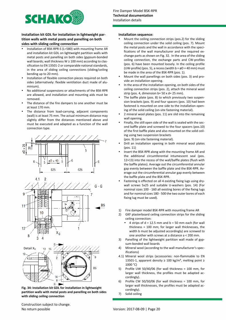
Installation kit GDL for installation in lightweight par-tition walls with metal posts and panelling on both sides with sliding ceiling connection Installation of BSK-RPR-S (L=580) with mounting frame AR
and installation kit GDL on lightweight partition walls with metal posts and panelling on both sides (gypsum-bonded wall boards; wall thickness W ≥ 100 mm) according to clas-sification to EN 13501-2 or comparable national standards, in the area of sliding ceiling connections (sliding/ceiling bending up to 20 mm).
Installation of flexible connection pieces required on both sides (alternatively: flexible ventilation duct made of alu-minium).
No additional suspensions or attachments of the BSK-RPR are allowed, and installation and mounting aids must be removed.
The distance of the fire dampers to one another must be at least 170 mm.
The distance from load-carrying, adjacent components (wall) is at least 75 mm. The actual minimum distance may slightly differ from the distances mentioned above and must be executed and adapted as a function of the wall connection type.
Fig. 34: Installation kit GDL for installation in lightweight partition walls with metal posts and panelling on both sides with sliding ceiling connection
Installation sequence: Mount the ceiling connection strips (pos.2) for the sliding
ceiling connection under the solid ceiling (pos. 7). Mount the metal posts and the wall in accordance with the speci-fications of the wall manufacturer and the required ex-change parts as shown on Fig. 32. In the area of the sliding ceiling connection, the exchange parts and CW-profiles (pos. 6) have been mounted loosely. In the ceiling profile (UW-profile) (pos. 5), a recess (width b = øD + 40 mm) must be made in the area of the BSK-RPR (pos. 1).
Mount the wall panellings on both sides (pos. 3) and pro-vide an installation opening.
In the area of the installation opening, on both sides of the ceiling connection strips (pos. 2), attach the mineral wool strip (pos. 4, dimension b= 50 x d= 25 mm).
The baffle plate (pos. 8) to which previously two suspen-sion brackets (pos. 9) and four spacers (pos. 10) had been fastened is mounted on one side to the installation open-ing of the solid ceiling (on-site fastening material).
2 mineral wool plates (pos. 11) are slid into the remaining wall opening.
Finally, the still open side of the wall is sealed with the sec-ond baffle plate and screwed to the four spacers (pos.10) of the first baffle plate and also mounted on the solid ceil-ing using two suspension brackets (pos. 9) (on-site fastening material).
Drill an installation opening in both mineral wool plates (pos. 11)
Insert the BSK-RPR along with the mounting frame AR and the additional circumferential intumescent seal (pos. 12+13) into the recess of the wall/baffle plates (flush with the baffle plates). Average out the circumferential annular gap evenly between the baffle plate and the BSK-RPR. Av-erage out the circumferential annular gap evenly between the baffle plate and the BSK-RPR.
Fastening is effected on all 4 existing fixing lugs using dry-wall screws 5x25 and suitable U-washers (pos. 14) (For nominal sizes 100 - 160 all existing bores of the fixing lugs and for nominal sizes 180 - 500 the two outer bores of each fixing lug must be used).
1) Fire damper model BSK-RPR with mounting frame AR 2) GKF plasterboard ceiling connection strips for the sliding
ceiling connection: 4 strips of d = 12.5 mm and b = 50 mm each (for wall
thickness = 100 mm; for larger wall thicknesses, the width b must be adjusted accordingly) are screwed to one another with screws at a distance a < 200 mm.
3) Panelling of the lightweight partition wall made of gyp-sum-bonded wall boards
4) Mineral wool (according to the wall manufacturer's spec-ifications)
4.1) Mineral wool strips (accessories: non-flammable to EN 13501-1, apparent density ≥ 100 kg/m³, melting point ≥ 1000 °C)
5) Profile UW 50/40/06 (for wall thickness = 100 mm, for larger wall thickness, the profiles must be adapted ac-cordingly).
6) Profile CW 50/50/06 (for wall thickness = 100 mm, for larger wall thicknesses, the profiles must be adapted ac-cordingly).
7) Solid ceiling
Detail XG
Fire Damper Model BSK-RPR Technical documentation Installation details
Construction subject to change. No return possible Version: 2017-08-09 | Page 21
8) Baffle plate (accessories: thickness d = 30 mm) 9) Suspension angle (accessories) 10) Spacer (accessories, length according to wall thickness).
The exact wall thickness/es must be taken into account and specified when ordering.
11) Mineral wool plates (accessories: non-flammable to EN 13501-1, apparent density ≥ 100 kg/m³, melting point ≥ 1000 °C)
12) Intumescent seal (distance from the mounting frame ≙ wall thickness + 30 mm, mounted, if necessary, on site)
13) Intumescent seal (mounted ex works) 14) Fastening screw Ø 5x25 (accessories) with suitable U-
washer (ø 5.3 - ISO 7093). For nominal sizes 100 - 160 all existing bores of the fixing lugs and for nominal sizes 180 - 500 the two outer bores of each fixing lug must be used.
15) Spacer screw M5 x 45 (ISO 4017) with suitable U-washer (ø 5.5 - ISO 7094).
Fire Damper Model BSK-RPR Technical documentation Installation details
Construction subject to change. No return possible Version: 2017-08-09 | Page 22
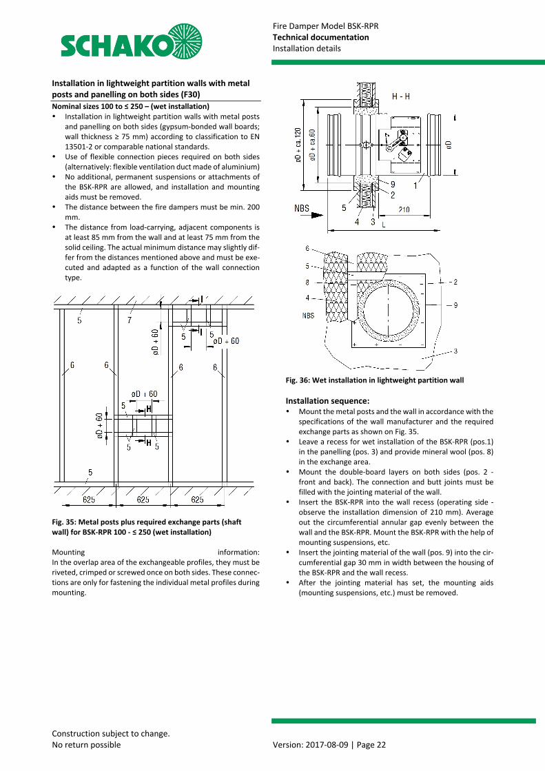
Installation in lightweight partition walls with metal posts and panelling on both sides (F30) Nominal sizes 100 to ≤ 250 – (wet installation) Installation in lightweight partition walls with metal posts
and panelling on both sides (gypsum-bonded wall boards; wall thickness ≥ 75 mm) according to classification to EN 13501-2 or comparable national standards.
Use of flexible connection pieces required on both sides (alternatively: flexible ventilation duct made of aluminium)
No additional, permanent suspensions or attachments of the BSK-RPR are allowed, and installation and mounting aids must be removed.
The distance between the fire dampers must be min. 200 mm.
The distance from load-carrying, adjacent components is at least 85 mm from the wall and at least 75 mm from the solid ceiling. The actual minimum distance may slightly dif-fer from the distances mentioned above and must be exe-cuted and adapted as a function of the wall connection type.
Fig. 35: Metal posts plus required exchange parts (shaft wall) for BSK-RPR 100 - ≤ 250 (wet installation) Mounting information: In the overlap area of the exchangeable profiles, they must be riveted, crimped or screwed once on both sides. These connec-tions are only for fastening the individual metal profiles during mounting.
Fig. 36: Wet installation in lightweight partition wall Installation sequence: Mount the metal posts and the wall in accordance with the
specifications of the wall manufacturer and the required exchange parts as shown on Fig. 35.
Leave a recess for wet installation of the BSK-RPR (pos.1) in the panelling (pos. 3) and provide mineral wool (pos. 8) in the exchange area.
Mount the double-board layers on both sides (pos. 2 - front and back). The connection and butt joints must be filled with the jointing material of the wall.
Insert the BSK-RPR into the wall recess (operating side - observe the installation dimension of 210 mm). Average out the circumferential annular gap evenly between the wall and the BSK-RPR. Mount the BSK-RPR with the help of mounting suspensions, etc.
Insert the jointing material of the wall (pos. 9) into the cir-cumferential gap 30 mm in width between the housing of the BSK-RPR and the wall recess.
After the jointing material has set, the mounting aids (mounting suspensions, etc.) must be removed.

Fire Damper Model BSK-RPR Technical documentation Installation details
Construction subject to change. No return possible Version: 2017-08-09 | Page 23
Installation close to ceiling (solid ceiling) Installation in lightweight partition walls with metal posts
and panelling on both sides (gypsum-bonded wall boards; wall thickness ≥ 75 mm) according to classification to EN 13501-2 or comparable national standards.
Use of flexible connection pieces required on both sides (alternatively: flexible ventilation duct made of aluminium)
No additional, permanent suspensions or attachments of the BSK-RPR are allowed, and installation and mounting aids must be removed.
Installation directly under the solid ceiling must be carried out during assembly of the wall and does not constitute a sliding ceiling connection.
The distance between the fire dampers must be min. 200 mm.
The distance from load-carrying, adjacent components is at least 85 mm from the wall and at least 75 mm from the solid ceiling. The actual minimum distance may slightly dif-fer from the distances mentioned above and must be exe-cuted and adapted as a function of the wall connection type.
Fig. 37: Wet installation in lightweight partition wall directly under the solid ceiling (BSK-RPR 100 - ≤ 250) Installation sequence: Mount the metal posts and the wall in accordance with the
specifications of the wall manufacturer and the required exchange parts as shown on Fig. 35. Before attaching the UW-profile (pos. 5) necessary for the circumferential metal profile frame in the ceiling area, a mineral wool strip ap-prox 50 x 40 mm (pos. 4) must be incorporated in the UW-profile at the ceiling.
Leave a recess for wet installation of the BSK-RPR (pos.1) in the panelling and provide mineral wool in the exchange area.
Mount the double-board layers on both sides (pos. 2 - front and back). The connection and butt joints must be filled with the jointing material of the wall.
Insert the BSK-RPR into the wall recess (operating side - observe the installation dimension of 210 mm). Average out the circumferential annular gap evenly between the wall and the BSK-RPR. Mount the BSK-RPR with the help of mounting suspensions, etc.
Insert the jointing material of the wall (pos. 9) into the cir-cumferential gap 30 mm in width between the housing of the BSK-RPR and the wall recess.
After the jointing material has set, the mounting aids (mounting suspensions, etc.) must be removed.
1) Fire damper type BSK-RPR 2) Doubling (plaster board, on both sides 1 x d=12.5mm
each) Fastening: Drywall screws TN 3.5x35, a ≤ 250 mm, or at
least 2 screws per side, connection and butt joints of the double-board layers must be filled with the jointing material of the wall.
3) Panelling of the lightweight partition wall made of gyp-sum-bonded wall boards
4) Mineral wool (according to the wall manufacturer's spec-ifications)
5) Profile UW 50/40/06 6) Profile CW 50/50/06 7) Solid ceiling 8) Mineral wool (non-flammable according to EN13501-1,
apparent density ≥ 100 kg/m³, melting point ≥ 1000°C) 9) Plaster joint filling with jointing material of the wall

Fire Damper Model BSK-RPR Technical documentation Installation details
Construction subject to change. No return possible Version: 2017-08-09 | Page 24
Installation with mounting AR in lightweight partition walls with metal posts and panelling on both sides (F30) Nominal sizes 100 to 500 - (dry installation) Installation with mounting frame AR in lightweight parti-
tion walls with metal posts and panelling on both sides (gypsum-bonded wall boards; wall thickness ≥ 75 mm) ac-cording to classification to EN 13501-2 or comparable na-tional standards.
Use of flexible connection pieces required on both sides (alternatively: flexible ventilation duct made of aluminium)
No additional, permanent suspensions or attachments of the BSK-RPR are allowed, and installation and mounting aids must be removed.
The distance between the fire dampers must be min. 200 mm.
The distance from load-carrying, adjacent components (wall / solid ceiling) is at least 75 mm. The actual minimum distance may slightly differ from the distances mentioned above and must be executed and adapted as a function of the wall connection type.
The BSK-RPR can be installed with mounting frame AR at any desired position, taking into account the minimum dis-tances in the lightweight partition wall, independently of the existing metal post profiles associated with the wall. This allows the damper to be installed in a previously com-pletely panelled wall.
The proposed installation shown refers to the damper sizes dia. 224 to dia. 500 mm. For all other nominal sizes, installation details can be seen from page 25.
Fig. 38: Metal posts plus required exchange parts for BSK-RPR with mounting frame AR (dry mounting)
Mounting information: In the overlap area of the exchangeable profiles, they must be riveted, crimped or screwed once on both sides. These connec-tions are only for fastening the individual metal profiles during mounting.
Fig. 39: Dry installation on lightweight partition wall with mounting frame AR
Installation sequence: Mount the metal posts and the wall in accordance with the
specifications of the wall manufacturer and the required exchange parts as shown on Fig. 36.
Leave a recess for dry installation of the BSK-RPR (pos.1) in the panelling (pos. 3) and provide mineral wool in the ex-change area.
Fill the square recess with the wall mineral wool. Slide in UW-exchange profiles (pos. 5) and screw them (drywall screws TN 3.5x35) to the wall panelling.
Introduce mineral wool (pos. 8) into the exchange area ac-cording to the exchange dimensions.
Insert the BSK-RPR along with the mounting frame AR into the recess of the wall (flush with the wall). Average out the circumferential annular gap evenly between the wall and the BSK-RPR.
Fastening is effected on all 4 existing fixing lugs using dry-wall screws TN 3.5x35 and suitable U-washers (pos. 2) (For nominal sizes 100 - 160 all existing bores of the fixing lugs and for nominal sizes 180 - 500 the two outer bores of each fixing lug must be used).
Detail XJ
Fire Damper Model BSK-RPR Technical documentation Installation details
Construction subject to change. No return possible Version: 2017-08-09 | Page 25
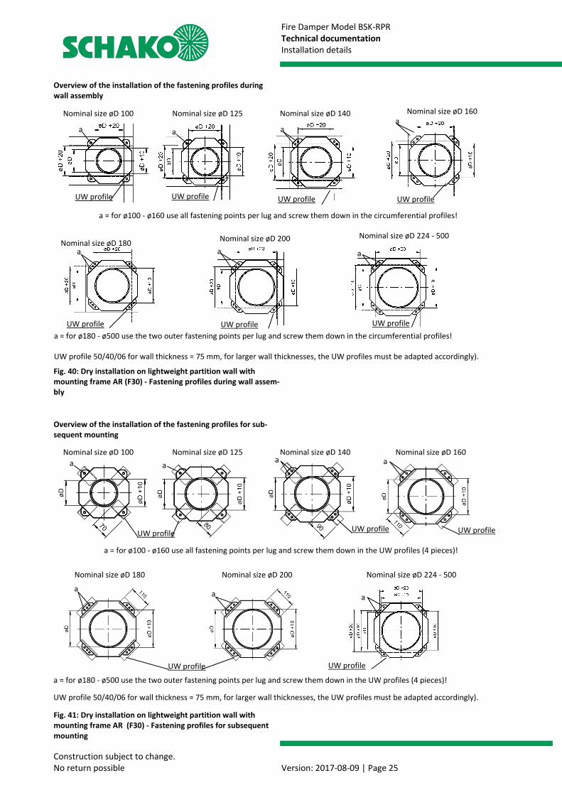
Overview of the installation of the fastening profiles during wall assembly
Fig. 40: Dry installation on lightweight partition wall with mounting frame AR (F30) - Fastening profiles during wall assem-bly
Overview of the installation of the fastening profiles for sub-sequent mounting
Fig. 41: Dry installation on lightweight partition wall with mounting frame AR (F30) - Fastening profiles for subsequent mounting
a = for ø180 - ø500 use the two outer fastening points per lug and screw them down in the UW profiles (4 pieces)!
Nominal size øD 100
a = for ø180 - ø500 use the two outer fastening points per lug and screw them down in the circumferential profiles!
Nominal size øD 125 Nominal size øD 140
UW profileUW profile
UW profile 50/40/06 for wall thickness = 75 mm, for larger wall thicknesses, the UW profiles must be adapted accordingly).
UW profile
a = for ø100 - ø160 use all fastening points per lug and screw them down in the circumferential profiles!
a
Nominal size øD 180 Nominal size øD 200
Nominal size øD 100 Nominal size øD 125 Nominal size øD 140 Nominal size øD 160
UW profile
a = for ø100 - ø160 use all fastening points per lug and screw them down in the UW profiles (4 pieces)!
UW profile
a a
UW profile
a
Nominal size øD 180 Nominal size øD 200
a
Nominal size øD 224 - 500
a a
UW profile 50/40/06 for wall thickness = 75 mm, for larger wall thicknesses, the UW profiles must be adapted accordingly).
a
Nominal size øD 224 - 500
Nominal size øD 160
aa a
UW profile UW profile
UW profile UW profile UW profile
aa a
UW profile
Fire Damper Model BSK-RPR Technical documentation Installation details
Construction subject to change. No return possible Version: 2017-08-09 | Page 26
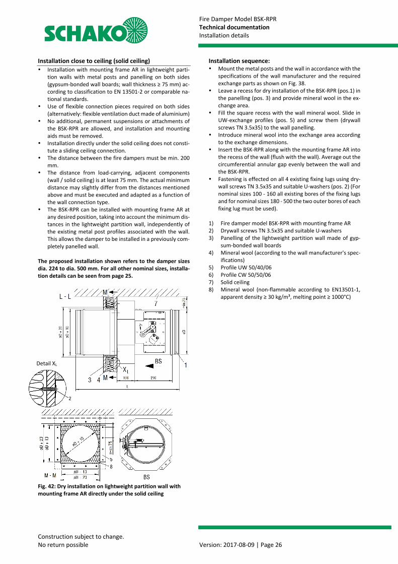
Installation close to ceiling (solid ceiling) Installation with mounting frame AR in lightweight parti-
tion walls with metal posts and panelling on both sides (gypsum-bonded wall boards; wall thickness ≥ 75 mm) ac-cording to classification to EN 13501-2 or comparable na-tional standards.
Use of flexible connection pieces required on both sides (alternatively: flexible ventilation duct made of aluminium)
No additional, permanent suspensions or attachments of the BSK-RPR are allowed, and installation and mounting aids must be removed.
Installation directly under the solid ceiling does not consti-tute a sliding ceiling connection.
The distance between the fire dampers must be min. 200 mm.
The distance from load-carrying, adjacent components (wall / solid ceiling) is at least 75 mm. The actual minimum distance may slightly differ from the distances mentioned above and must be executed and adapted as a function of the wall connection type.
The BSK-RPR can be installed with mounting frame AR at any desired position, taking into account the minimum dis-tances in the lightweight partition wall, independently of the existing metal post profiles associated with the wall. This allows the damper to be installed in a previously com-pletely panelled wall.
The proposed installation shown refers to the damper sizes dia. 224 to dia. 500 mm. For all other nominal sizes, installa-tion details can be seen from page 25.
Fig. 42: Dry installation on lightweight partition wall with mounting frame AR directly under the solid ceiling
Installation sequence: Mount the metal posts and the wall in accordance with the
specifications of the wall manufacturer and the required exchange parts as shown on Fig. 38.
Leave a recess for dry installation of the BSK-RPR (pos.1) in the panelling (pos. 3) and provide mineral wool in the ex-change area.
Fill the square recess with the wall mineral wool. Slide in UW-exchange profiles (pos. 5) and screw them (drywall screws TN 3.5x35) to the wall panelling.
Introduce mineral wool into the exchange area according to the exchange dimensions.
Insert the BSK-RPR along with the mounting frame AR into the recess of the wall (flush with the wall). Average out the circumferential annular gap evenly between the wall and the BSK-RPR.
Fastening is effected on all 4 existing fixing lugs using dry-wall screws TN 3.5x35 and suitable U-washers (pos. 2) (For nominal sizes 100 - 160 all existing bores of the fixing lugs and for nominal sizes 180 - 500 the two outer bores of each fixing lug must be used).
1) Fire damper model BSK-RPR with mounting frame AR 2) Drywall screws TN 3.5x35 and suitable U-washers 3) Panelling of the lightweight partition wall made of gyp-
sum-bonded wall boards 4) Mineral wool (according to the wall manufacturer's spec-
ifications) 5) Profile UW 50/40/06 6) Profile CW 50/50/06 7) Solid ceiling 8) Mineral wool (non-flammable according to EN13501-1,
apparent density ≥ 30 kg/m³, melting point ≥ 1000°C)
Detail XL
Fire Damper Model BSK-RPR Technical documentation Installation details
Construction subject to change. No return possible Version: 2017-08-09 | Page 27
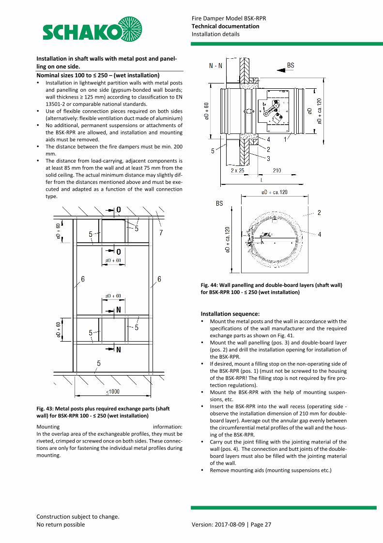
Installation in shaft walls with metal post and panel-ling on one side. Nominal sizes 100 to ≤ 250 – (wet installation) Installation in lightweight partition walls with metal posts
and panelling on one side (gypsum-bonded wall boards; wall thickness ≥ 125 mm) according to classification to EN 13501-2 or comparable national standards.
Use of flexible connection pieces required on both sides (alternatively: flexible ventilation duct made of aluminium)
No additional, permanent suspensions or attachments of the BSK-RPR are allowed, and installation and mounting aids must be removed.
The distance between the fire dampers must be min. 200 mm.
The distance from load-carrying, adjacent components is at least 85 mm from the wall and at least 75 mm from the solid ceiling. The actual minimum distance may slightly dif-fer from the distances mentioned above and must be exe-cuted and adapted as a function of the wall connection type.
Fig. 43: Metal posts plus required exchange parts (shaft wall) for BSK-RPR 100 - ≤ 250 (wet installation)
Mounting information: In the overlap area of the exchangeable profiles, they must be riveted, crimped or screwed once on both sides. These connec-tions are only for fastening the individual metal profiles during mounting.
Fig. 44: Wall panelling and double-board layers (shaft wall) for BSK-RPR 100 - ≤ 250 (wet installation) Installation sequence: Mount the metal posts and the wall in accordance with the
specifications of the wall manufacturer and the required exchange parts as shown on Fig. 41.
Mount the wall panelling (pos. 3) and double-board layer (pos. 2) and drill the installation opening for installation of the BSK-RPR.
If desired, mount a filling stop on the non-operating side of the BSK-RPR (pos. 1) (must not be screwed to the housing of the BSK-RPR! The filling stop is not required by fire pro-tection regulations).
Mount the BSK-RPR with the help of mounting suspen-sions, etc.
Insert the BSK-RPR into the wall recess (operating side - observe the installation dimension of 210 mm for double-board layer). Average out the annular gap evenly between the circumferential metal profiles of the wall and the hous-ing of the BSK-RPR.
Carry out the joint filling with the jointing material of the wall (pos. 4). The connection and butt joints of the double-board layers must also be filled with the jointing material of the wall.
Remove mounting aids (mounting suspensions etc.)
Fire Damper Model BSK-RPR Technical documentation Installation details
Construction subject to change. No return possible Version: 2017-08-09 | Page 28
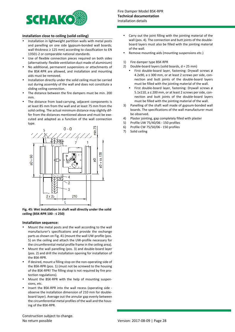
Installation close to ceiling (solid ceiling) Installation in lightweight partition walls with metal posts
and panelling on one side (gypsum-bonded wall boards; wall thickness ≥ 125 mm) according to classification to EN 13501-2 or comparable national standards.
Use of flexible connection pieces required on both sides (alternatively: flexible ventilation duct made of aluminium)
No additional, permanent suspensions or attachments of the BSK-RPR are allowed, and installation and mounting aids must be removed.
Installation directly under the solid ceiling must be carried out during assembly of the wall and does not constitute a sliding ceiling connection.
The distance between the fire dampers must be min. 200 mm.
The distance from load-carrying, adjacent components is at least 85 mm from the wall and at least 75 mm from the solid ceiling. The actual minimum distance may slightly dif-fer from the distances mentioned above and must be exe-cuted and adapted as a function of the wall connection type.
Fig. 45: Wet installation in shaft wall directly under the solid ceiling (BSK-RPR 100 - ≤ 250) Installation sequence: Mount the metal posts and the wall according to the wall
manufacturer's specifications and provide the exchange parts as shown on Fig. 41 (mount the wall UW-profile (pos. 5) on the ceiling and attach the UW-profile necessary for the circumferential metal profile frame in the ceiling area).
Mount the wall panelling (pos. 3) and double-board layer (pos. 2) and drill the installation opening for installation of the BSK-RPR.
If desired, mount a filling stop on the non-operating side of the BSK-RPR (pos. 1) (must not be screwed to the housing of the BSK-RPR! The filling stop is not required by fire pro-tection regulations).
Mount the BSK-RPR with the help of mounting suspen-sions, etc.
Insert the BSK-RPR into the wall recess (operating side - observe the installation dimension of 210 mm for double-board layer). Average out the annular gap evenly between the circumferential metal profiles of the wall and the hous-ing of the BSK-RPR.
Carry out the joint filling with the jointing material of the wall (pos. 4). The connection and butt joints of the double-board layers must also be filled with the jointing material of the wall.
Remove mounting aids (mounting suspensions etc.) 1) Fire damper type BSK-RPR 2) Double-board layers (solid boards, d = 25 mm) First double-board layer, fastening: Drywall screws ø
4.2x90, a ≤ 300 mm, or at least 2 screws per side, con-nection and butt joints of the double-board layers must be filled with the jointing material of the wall.
First double-board layer, fastening: Drywall screws ø 5.1x110, a ≤ 200 mm, or at least 2 screws per side, con-nection and butt joints of the double-board layers must be filled with the jointing material of the wall.
3) Panelling of the shaft wall made of gypsum-bonded wall boards. The specifications of the wall manufacturer must be observed.
4) Plaster jointing, gap completely filled with plaster 5) Profile UW 75/40/06 - 150 profiles 6) Profile CW 75/50/06 - 150 profiles 7) Solid ceiling
Fire Damper Model BSK-RPR Technical documentation Installation details
Construction subject to change. No return possible Version: 2017-08-09 | Page 29
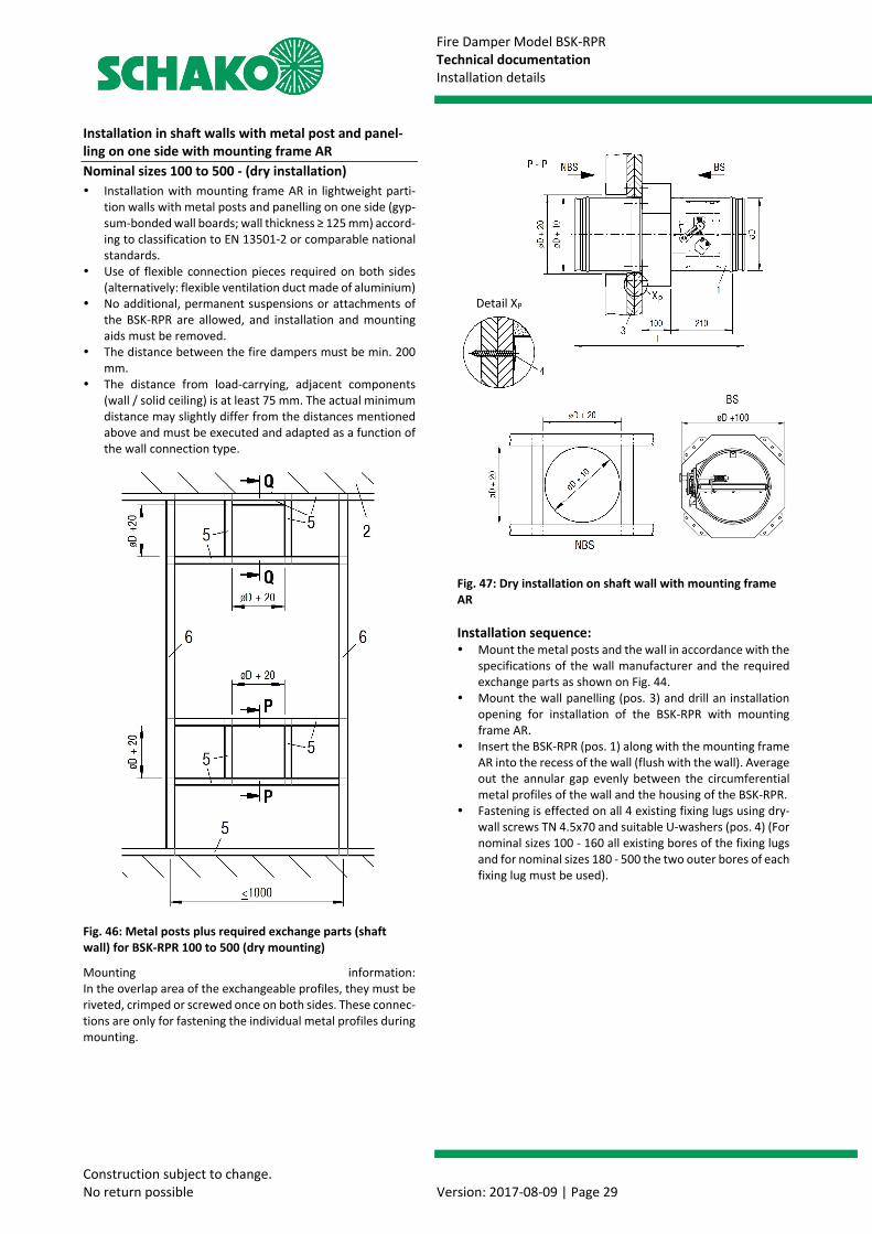
Installation in shaft walls with metal post and panel-ling on one side with mounting frame AR Nominal sizes 100 to 500 - (dry installation) Installation with mounting frame AR in lightweight parti-
tion walls with metal posts and panelling on one side (gyp-sum-bonded wall boards; wall thickness ≥ 125 mm) accord-ing to classification to EN 13501-2 or comparable national standards.
Use of flexible connection pieces required on both sides (alternatively: flexible ventilation duct made of aluminium)
No additional, permanent suspensions or attachments of the BSK-RPR are allowed, and installation and mounting aids must be removed.
The distance between the fire dampers must be min. 200 mm.
The distance from load-carrying, adjacent components (wall / solid ceiling) is at least 75 mm. The actual minimum distance may slightly differ from the distances mentioned above and must be executed and adapted as a function of the wall connection type.
Fig. 46: Metal posts plus required exchange parts (shaft wall) for BSK-RPR 100 to 500 (dry mounting)
Mounting information: In the overlap area of the exchangeable profiles, they must be riveted, crimped or screwed once on both sides. These connec-tions are only for fastening the individual metal profiles during mounting.
Fig. 47: Dry installation on shaft wall with mounting frame AR Installation sequence: Mount the metal posts and the wall in accordance with the
specifications of the wall manufacturer and the required exchange parts as shown on Fig. 44.
Mount the wall panelling (pos. 3) and drill an installation opening for installation of the BSK-RPR with mounting frame AR.
Insert the BSK-RPR (pos. 1) along with the mounting frame AR into the recess of the wall (flush with the wall). Average out the annular gap evenly between the circumferential metal profiles of the wall and the housing of the BSK-RPR.
Fastening is effected on all 4 existing fixing lugs using dry-wall screws TN 4.5x70 and suitable U-washers (pos. 4) (For nominal sizes 100 - 160 all existing bores of the fixing lugs and for nominal sizes 180 - 500 the two outer bores of each fixing lug must be used).
Detail XP
Fire Damper Model BSK-RPR Technical documentation Installation details
Construction subject to change. No return possible Version: 2017-08-09 | Page 30
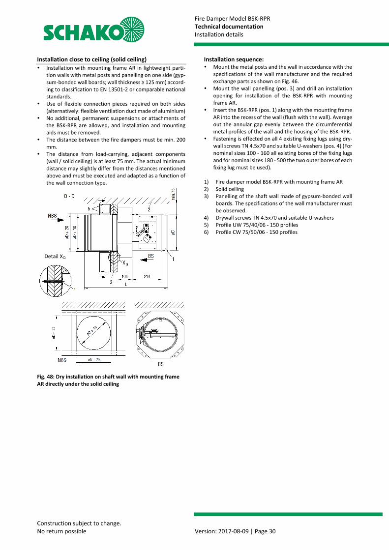
Installation close to ceiling (solid ceiling) Installation with mounting frame AR in lightweight parti-
tion walls with metal posts and panelling on one side (gyp-sum-bonded wall boards; wall thickness ≥ 125 mm) accord-ing to classification to EN 13501-2 or comparable national standards.
Use of flexible connection pieces required on both sides (alternatively: flexible ventilation duct made of aluminium)
No additional, permanent suspensions or attachments of the BSK-RPR are allowed, and installation and mounting aids must be removed.
The distance between the fire dampers must be min. 200 mm.
The distance from load-carrying, adjacent components (wall / solid ceiling) is at least 75 mm. The actual minimum distance may slightly differ from the distances mentioned above and must be executed and adapted as a function of the wall connection type.
Fig. 48: Dry installation on shaft wall with mounting frame AR directly under the solid ceiling
Installation sequence: Mount the metal posts and the wall in accordance with the
specifications of the wall manufacturer and the required exchange parts as shown on Fig. 46.
Mount the wall panelling (pos. 3) and drill an installation opening for installation of the BSK-RPR with mounting frame AR.
Insert the BSK-RPR (pos. 1) along with the mounting frame AR into the recess of the wall (flush with the wall). Average out the annular gap evenly between the circumferential metal profiles of the wall and the housing of the BSK-RPR.
Fastening is effected on all 4 existing fixing lugs using dry-wall screws TN 4.5x70 and suitable U-washers (pos. 4) (For nominal sizes 100 - 160 all existing bores of the fixing lugs and for nominal sizes 180 - 500 the two outer bores of each fixing lug must be used).
1) Fire damper model BSK-RPR with mounting frame AR 2) Solid ceiling 3) Panelling of the shaft wall made of gypsum-bonded wall
boards. The specifications of the wall manufacturer must be observed.
4) Drywall screws TN 4.5x70 and suitable U-washers 5) Profile UW 75/40/06 - 150 profiles 6) Profile CW 75/50/06 - 150 profiles
Detail XQ
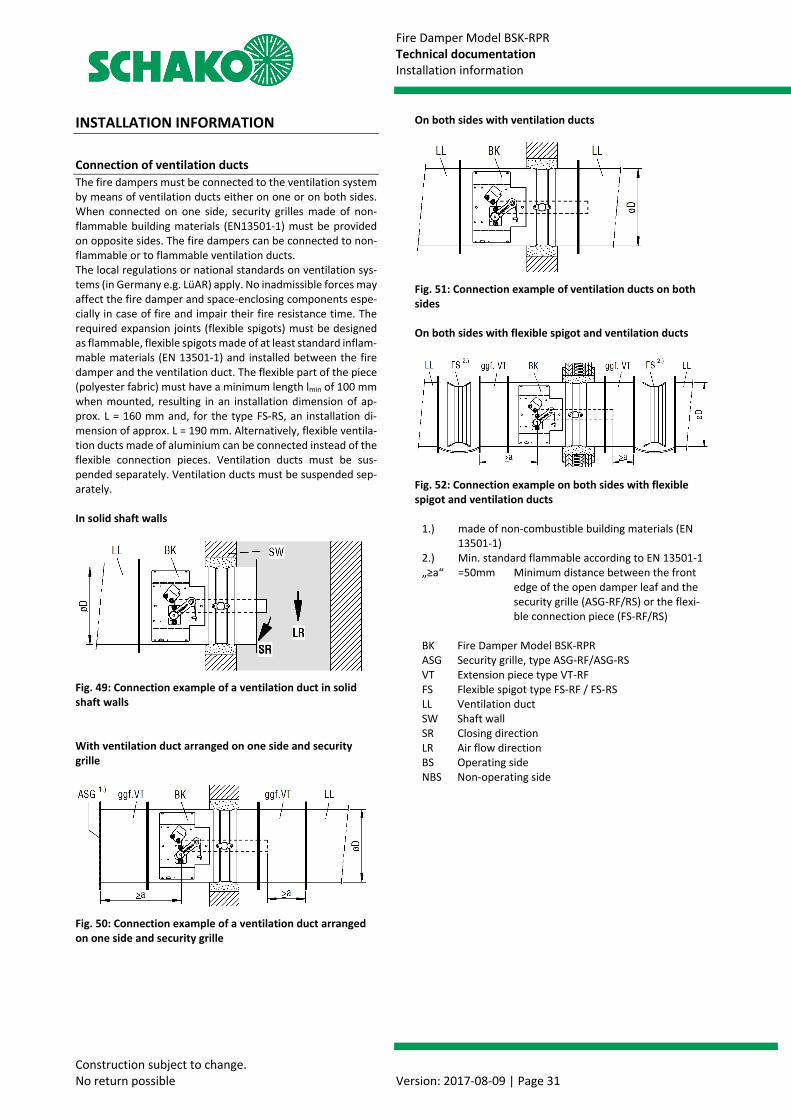
Fire Damper Model BSK-RPR Technical documentation Installation information
Construction subject to change. No return possible Version: 2017-08-09 | Page 31
INSTALLATION INFORMATION
Connection of ventilation ducts The fire dampers must be connected to the ventilation system by means of ventilation ducts either on one or on both sides. When connected on one side, security grilles made of non-flammable building materials (EN13501-1) must be provided on opposite sides. The fire dampers can be connected to non-flammable or to flammable ventilation ducts. The local regulations or national standards on ventilation sys-tems (in Germany e.g. LüAR) apply. No inadmissible forces may affect the fire damper and space-enclosing components espe-cially in case of fire and impair their fire resistance time. The required expansion joints (flexible spigots) must be designed as flammable, flexible spigots made of at least standard inflam-mable materials (EN 13501-1) and installed between the fire damper and the ventilation duct. The flexible part of the piece (polyester fabric) must have a minimum length lmin of 100 mm when mounted, resulting in an installation dimension of ap-prox. L = 160 mm and, for the type FS-RS, an installation di-mension of approx. L = 190 mm. Alternatively, flexible ventila-tion ducts made of aluminium can be connected instead of the flexible connection pieces. Ventilation ducts must be sus-pended separately. Ventilation ducts must be suspended sep-arately. In solid shaft walls
Fig. 49: Connection example of a ventilation duct in solid shaft walls With ventilation duct arranged on one side and security grille
Fig. 50: Connection example of a ventilation duct arranged on one side and security grille
On both sides with ventilation ducts
Fig. 51: Connection example of ventilation ducts on both sides On both sides with flexible spigot and ventilation ducts
Fig. 52: Connection example on both sides with flexible spigot and ventilation ducts
1.) made of non-combustible building materials (EN 13501-1)
2.) Min. standard flammable according to EN 13501-1 „≥a“ =50mm Minimum distance between the front
edge of the open damper leaf and the security grille (ASG-RF/RS) or the flexi-ble connection piece (FS-RF/RS)
BK Fire Damper Model BSK-RPR ASG Security grille, type ASG-RF/ASG-RS VT Extension piece type VT-RF FS Flexible spigot type FS-RF / FS-RS LL Ventilation duct SW Shaft wall SR Closing direction LR Air flow direction BS Operating side NBS Non-operating side
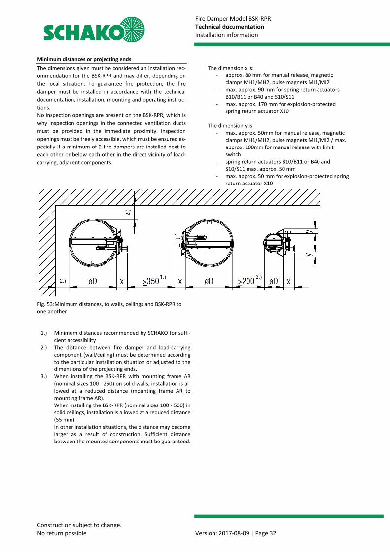
Fire Damper Model BSK-RPR Technical documentation Installation information
Construction subject to change. No return possible Version: 2017-08-09 | Page 32
Minimum distances or projecting ends The dimensions given must be considered an installation rec-ommendation for the BSK-RPR and may differ, depending on the local situation. To guarantee fire protection, the fire damper must be installed in accordance with the technical documentation, installation, mounting and operating instruc-tions. No inspection openings are present on the BSK-RPR, which is why inspection openings in the connected ventilation ducts must be provided in the immediate proximity. Inspection openings must be freely accessible, which must be ensured es-pecially if a minimum of 2 fire dampers are installed next to each other or below each other in the direct vicinity of load-carrying, adjacent components.
Fig. 53:Minimum distances, to walls, ceilings and BSK-RPR to one another
1.) Minimum distances recommended by SCHAKO for suffi-cient accessibility
2.) The distance between fire damper and load-carrying component (wall/ceiling) must be determined according to the particular installation situation or adjusted to the dimensions of the projecting ends.
3.) When installing the BSK-RPR with mounting frame AR (nominal sizes 100 - 250) on solid walls, installation is al-lowed at a reduced distance (mounting frame AR to mounting frame AR). When installing the BSK-RPR (nominal sizes 100 - 500) in solid ceilings, installation is allowed at a reduced distance (55 mm). In other installation situations, the distance may become larger as a result of construction. Sufficient distance between the mounted components must be guaranteed.
The dimension x is: - approx. 80 mm for manual release, magnetic
clamps MH1/MH2, pulse magnets MI1/MI2 - max. approx. 90 mm for spring return actuators
B10/B11 or B40 and S10/S11 - max. approx. 170 mm for explosion-protected
spring return actuator X10
The dimension y is: - max. approx. 50mm for manual release, magnetic
clamps MH1/MH2, pulse magnets MI1/MI2 / max. approx. 100mm for manual release with limit switch
- spring return actuators B10/B11 or B40 and S10/S11 max. approx. 50 mm
- max. approx. 50 mm for explosion-protected spring return actuator X10
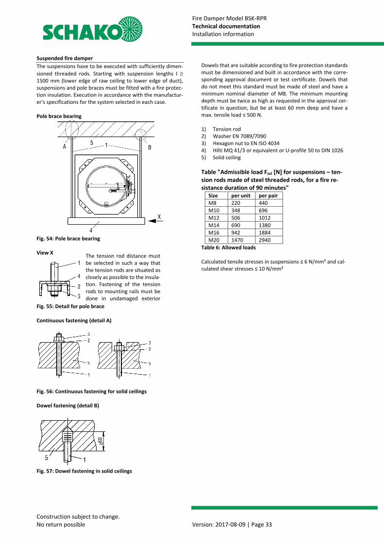
Fire Damper Model BSK-RPR Technical documentation Installation information
Construction subject to change. No return possible Version: 2017-08-09 | Page 33
Suspended fire damper The suspensions have to be executed with sufficiently dimen-sioned threaded rods. Starting with suspension lengths I ≥ 1500 mm (lower edge of raw ceiling to lower edge of duct), suspensions and pole braces must be fitted with a fire protec-tion insulation. Execution in accordance with the manufactur-er's specifications for the system selected in each case. Pole brace bearing
Fig. 54: Pole brace bearing View X
Fig. 55: Detail for pole brace Continuous fastening (detail A)
Fig. 56: Continuous fastening for solid ceilings Dowel fastening (detail B)
Fig. 57: Dowel fastening in solid ceilings
Dowels that are suitable according to fire protection standards must be dimensioned and built in accordance with the corre-sponding approval document or test certificate. Dowels that do not meet this standard must be made of steel and have a minimum nominal diameter of M8. The minimum mounting depth must be twice as high as requested in the approval cer-tificate in question, but be at least 60 mm deep and have a max. tensile load ≤ 500 N. 1) Tension rod 2) Washer EN 7089/7090 3) Hexagon nut to EN ISO 4034 4) Hilti MQ 41/3 or equivalent or U-profile 50 to DIN 1026 5) Solid ceiling Table "Admissible load Fzul [N] for suspensions – ten-sion rods made of steel threaded rods, for a fire re-sistance duration of 90 minutes"
Size per unit per pair M8 220 440 M10 348 696 M12 506 1012 M14 690 1380 M16 942 1884 M20 1470 2940
Table 6: Allowed loads Calculated tensile stresses in suspensions ≤ 6 N/mm² and cal-culated shear stresses ≤ 10 N/mm²
The tension rod distance must be selected in such a way that the tension rods are situated as closely as possible to the insula-tion. Fastening of the tension rods to mounting rails must be done in undamaged exterior
b
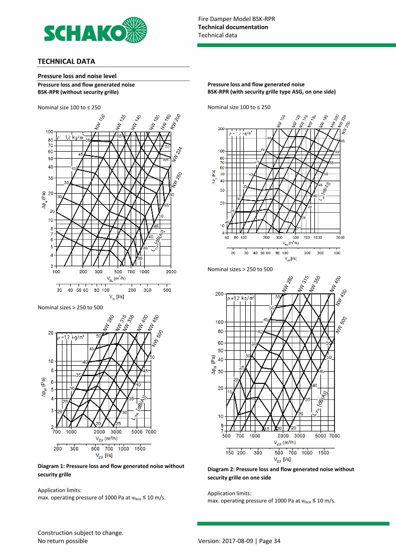
Fire Damper Model BSK-RPR Technical documentation Technical data
Construction subject to change. No return possible Version: 2017-08-09 | Page 34
TECHNICAL DATA
Pressure loss and noise level Pressure loss and flow generated noise BSK-RPR (without security grille) Nominal size 100 to ≤ 250
Nominal sizes > 250 to 500
Diagram 1: Pressure loss and flow generated noise without security grille Application limits: max. operating pressure of 1000 Pa at vface ≤ 10 m/s.
Pressure loss and flow generated noise BSK-RPR (with security grille type ASG, on one side)
Nominal size 100 to ≤ 250
Nominal sizes > 250 to 500
Diagram 2: Pressure loss and flow generated noise without security grille on one side Application limits: max. operating pressure of 1000 Pa at vface ≤ 10 m/s.
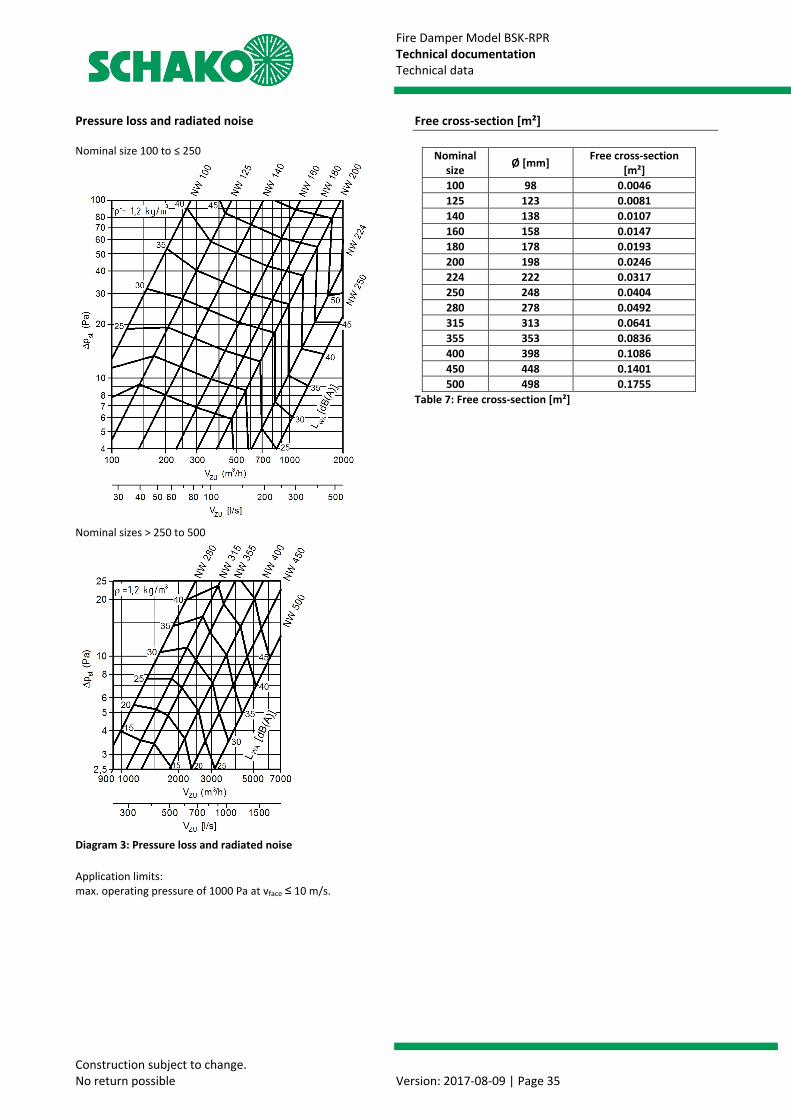
Fire Damper Model BSK-RPR Technical documentation Technical data
Construction subject to change. No return possible Version: 2017-08-09 | Page 35
Pressure loss and radiated noise Nominal size 100 to ≤ 250
Nominal sizes > 250 to 500
Diagram 3: Pressure loss and radiated noise Application limits: max. operating pressure of 1000 Pa at vface ≤ 10 m/s.
Free cross-section [m²]
Nominal size Ø [mm] Free cross-section
[m²] 100 98 0.0046 125 123 0.0081 140 138 0.0107 160 158 0.0147 180 178 0.0193 200 198 0.0246 224 222 0.0317 250 248 0.0404 280 278 0.0492 315 313 0.0641 355 353 0.0836 400 398 0.1086 450 448 0.1401 500 498 0.1755
Table 7: Free cross-section [m²]
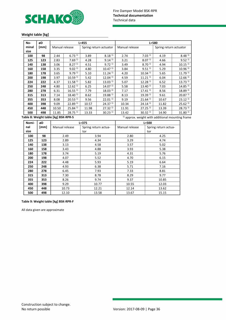
Fire Damper Model BSK-RPR Technical documentation Technical data
Construction subject to change. No return possible Version: 2017-08-09 | Page 36
Weight table [kg]
Table 8: Weight table [kg] BSK-RPR-S
Table 9: Weight table [kg] BSK-RPR-F All data given are approximate
No-minal size
øD [mm]
L=455 L=580 Manual release Spring return actuator Manual release Spring return actuator
100 98 2.44 6.73 1) 3.89 8.18 1) 2.74 7.03 1) 4.19 8.48 1) 125 123 2.83 7.69 1) 4.28 9.14 1) 3.21 8.07 1) 4.66 9.52 1) 140 138 3.06 8.27 1) 4.51 9.72 1) 3.49 8.70 1) 4.94 10.15 1) 160 158 3.35 9.02 1) 4.80 10.47 1) 3.84 9.51 1) 5.29 10.96 1) 180 178 3.65 9.79 1) 5.10 11.24 1) 4.20 10.34 1) 5.65 11.79 1) 200 198 3.97 10.59 1) 5.42 12.04 1) 4.59 11.21 1) 6.04 12.66 1) 224 222 4.37 11.58 1) 5.82 13.03 1) 5.07 12.28 1) 6.52 13.73 1) 250 248 4.80 12.62 1) 6.25 14.07 1) 5.58 13.40 1) 7.03 14.85 1) 280 278 6.31 16.55 1) 7.79 18.03 1) 7.17 17.41 1) 8.56 18.89 1) 315 313 7.14 18.40 1) 8.62 19.88 1) 8.13 19.39 1) 9.61 20.87 1) 355 353 8.08 20.53 1) 9.56 22.01 1) 9.19 21.64 1) 10.67 23.12 1) 400 398 9.09 22.89 1) 10.57 24.37 1) 10.34 24.14 1) 11.82 25.62 1) 450 448 10.50 25.84 1) 11.98 27.32 1) 11.91 27.25 1) 13.39 28.73 1) 500 498 11.85 28.75 1) 13.33 30.23 1) 13.42 30.32 1) 14.90 31.80 1)
Nomi-nal size
øD [mm]
L=375 L=500 Manual release Spring return actua-
tor Manual release Spring return actua-
tor 100 98 2.49 3.94 2.80 4.25 125 123 2.89 4.34 3.29 4.74 140 138 3.13 4.58 3.57 5.02 160 158 3.43 4.88 3.93 5.38 180 178 3.74 5.19 4.31 5.76 200 198 4.07 5.52 4.70 6.15 224 222 4.48 5.93 5.19 6.64 250 248 4.93 6.38 5.71 7.16 280 278 6.45 7.93 7.33 8.81 315 313 7.30 8.78 8.29 9.77 355 353 8.26 9.74 9.37 10.85 400 398 9.29 10.77 10.55 12.03 450 448 10.73 12.21 12.14 13.62 500 498 12.10 13.58 13.67 15.15
1) approx. weight with additional mounting frame

Fire Damper Model BSK-RPR Technical documentation Accessories
Construction subject to change. No return possible Version: 2017-08-09 | Page 37
ACCESSORIES Available at an extra charge
Model made of stainless steel material no. 1.4301 (V2A) or 1.4571 (V4A)
Model with additional DD coating (solvent-containing two-component top coat based on polyurethane varnish - RAL 7035 / light-grey) inside / outside
thermal release via fusible link 98°C (hot-air heating) Limit switch type ES, limit switch type ES-Ex, limit switch
EasyF-ETX (EasyBus) Electric spring return actuators B10/B11, B40, S10/S11,
X10,, Joventa - drives J30/J31/J40 upon request Magnetic clamps MH1 (24 V DC) / MH2 (230 V AC) Pulse magnets MI1 (24 V DC) / MI2 (230 V AC) Smoke detection system type RMS with abZ No. Z-78.6-
58. Usability depends on damper dimension. For a tech-nical description and documentation, see technical docu-mentation Smoke detection system RMS.
Signalling and switching bus system type EasyBus Fire damper mini-controller BKSYS Extension piece type VT-RF 1.) Assembly part type EBT 1.) (painted black matt on the in-
side) - required for installation of the smoke detection system type RMS
Duct connection spigot type RS 1.) Flexible spigot type FS-RF/FS-RS; PVC (normally inflamma-
ble to EN 13501-1), connection profile made of sheet steel 2.)
Security grille type ASG-RF/ASG-RS 1.) 1.) Standard design galvanised sheet steel, material No.
1.4301 or 1.4571, DD coating (RAL 7035 / light-grey) pos-sible.
2.) Standard design galvanised sheet steel, design material no. 1.4301 or 1.4571 possible.
LIMIT SWITCH
Limit switch type ES
Electric limit switch for position indicators "OPEN" and/or "CLOSED". Switching element including one NC and one NO contact each, 4 connections for M3.5 screw terminals for max. 2 mm². 250 V AC, Ie 6A, IP67 -using suitable cable glands M20 (on site).
Figure 58: Circuit diagram limit switch type ES
Damper positions that can be displayed: ESZ (type ES 1Z: "CLOSED") ESA (type ES 1A: "OPEN") EZA (type ES 2: "OPEN" and "CLOSED") Limit switch type ES-Ex
Limit switch for application in areas subject to explosion haz-ards
II 2G Ex d IIC T6/T5 Gb,
II 2D Ex tb lIIC T 80°C/ 95°C Db
IP65; 250V / 6A AC15; 230V / 0.25A DC13; -20°C ≤ Ta ≤ +65°C
Figure 59: Circuit diagram limit switch type ES-Ex
Damper positions that can be displayed: EXZ (type ES-Ex 1 Z: "CLOSED") EXA (type ES-Ex 1A: "OPEN") EX2 (type ES-Ex 2: "OPEN" and "CLOSED") Limit switch type EasyF-ETX
For a technical description and documentation of the limit switch ETX (type EasyF-ETX): see technical documentation sig-nalling and switching bus system EasyBus.
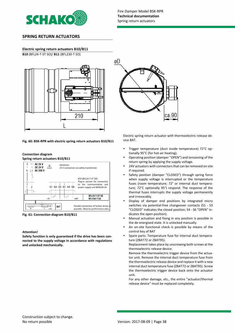
Fire Damper Model BSK-RPR Technical documentation Spring return actuators
Construction subject to change. No return possible Version: 2017-08-09 | Page 38
SPRING RETURN ACTUATORS
Electric spring return actuators B10/B11 B10 (BFL24-T-ST SO)/ B11 (BFL230-T SO)
Fig. 60: BSK-RPR with electric spring return actuators B10/B11 Connection diagram Spring return actuators B10/B11
Fig. 61: Connection diagram B10/B11 Attention! Safety function is only guaranteed if the drive has been con-nected to the supply voltage in accordance with regulations and unlocked mechanically.
Electric spring return actuator with thermoelectric release de-vice BAT. Trigger temperature (duct inside temperature) 72°C op-
tionally 95°C (for hot-air heating). Operating position (damper "OPEN") and tensioning of the
return spring by applying the supply voltage. 24V actuators with connectors that can be removed on site
if required. Safety position (damper "CLOSED") through spring force
when supply voltage is interrupted or the temperature fuses (room temperature; 72° or internal duct tempera-ture; 72°C optionally 95°) respond. The response of the thermal fuses interrupts the supply voltage permanently and irrevocably.
Display of damper end positions by integrated micro switches via potential-free changeover contacts (S1 - S3 "CLOSED" indicates the closed position; S4 - S6 "OPEN" in-dicates the open position).
Manual actuation and fixing in any position is possible in the de-energised state. It is unlocked manually.
An on-site functional check is possible by means of the control key of BAT
Spare parts: Temperature fuse for internal duct tempera-ture (ZBAT72 or ZBAT95). Replacement takes place by unscrewing both screws at the thermoelectric release device. Remove the thermoelectric trigger device from the actua-tor unit. Remove the internal duct temperature fuse from the thermoelectric release device and replace it with a new internal duct temperature fuse (ZBAT72 or ZBAT95). Screw the thermoelectric trigger device back onto the actuator unit. For any other damage, etc., the entire "actuator/thermal release device" must be replaced completely.
Attention: 24 V connection via safety transformer
B10 (BFL24-T-ST SO): Plug-in version for connection to the communication and power supply unit BKN230-24
Parallel connection of further drives is possible. Observe performance data.
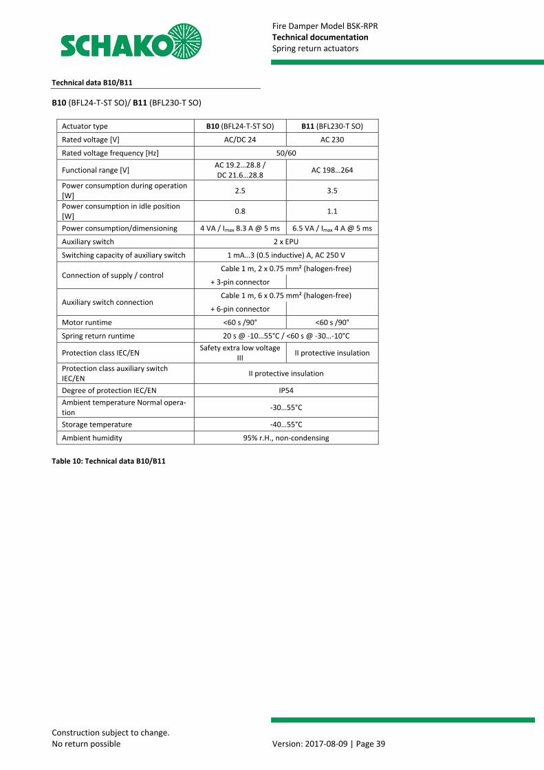
Fire Damper Model BSK-RPR Technical documentation Spring return actuators
Construction subject to change. No return possible Version: 2017-08-09 | Page 39
Technical data B10/B11
B10 (BFL24-T-ST SO)/ B11 (BFL230-T SO)
Table 10: Technical data B10/B11
Actuator type B10 (BFL24-T-ST SO) B11 (BFL230-T SO)
Rated voltage [V] AC/DC 24 AC 230
Rated voltage frequency [Hz] 50/60
Functional range [V] AC 19.2…28.8 / DC 21.6…28.8 AC 198…264
Power consumption during operation [W] 2.5 3.5
Power consumption in idle position [W] 0.8 1.1
Power consumption/dimensioning 4 VA / Imax 8.3 A @ 5 ms 6.5 VA / Imax 4 A @ 5 ms
Auxiliary switch 2 x EPU
Switching capacity of auxiliary switch 1 mA…3 (0.5 inductive) A, AC 250 V
Connection of supply / control Cable 1 m, 2 x 0.75 mm² (halogen-free)
+ 3-pin connector
Auxiliary switch connection Cable 1 m, 6 x 0.75 mm² (halogen-free)
+ 6-pin connector
Motor runtime <60 s /90° <60 s /90°
Spring return runtime 20 s @ -10…55°C / <60 s @ -30…-10°C
Protection class IEC/EN Safety extra low voltage III II protective insulation
Protection class auxiliary switch IEC/EN II protective insulation
Degree of protection IEC/EN IP54 Ambient temperature Normal opera-tion -30…55°C
Storage temperature -40…55°C
Ambient humidity 95% r.H., non-condensing
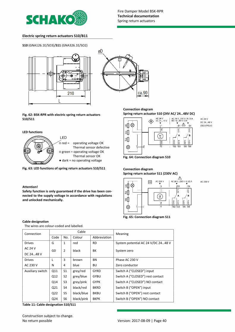
Fire Damper Model BSK-RPR Technical documentation Spring return actuators
Construction subject to change. No return possible Version: 2017-08-09 | Page 40
Electric spring return actuators S10/B11 S10 (GNA126.1E/SO3)/S11 (GNA326.1E/SO2)
Fig. 62: BSK-RPR with electric spring return actuators S10/S11 LED functions
Fig. 63: LED functions of spring return actuators S10/S11
Attention! Safety function is only guaranteed if the drive has been con-nected to the supply voltage in accordance with regulations and unlocked mechanically. Cable designation
Table 11: Cable designation S10/S11
Connection diagram Spring return actuator S10 (24V AC/ 24…48V DC)
Fig. 64: Connection diagram S10 Connection diagram Spring return actuator S11 (230V AC)
Fig. 65: Connection diagram S11
The wires are colour-coded and labelled.
Connection Cable Meaning Code No. Colour Abbreviation
Drives G 1 red RD System potential AC 24 V/DC 24…48 V AC 24 V
G0 2 black BK System zero DC 24…48 V Drives L 3 brown BN Phase AC 230 V AC 230 V N 4 blue BU Zero conductor
Auxiliary switch Q11 S1 grey/red GYRD Switch A (“CLOSED”) input Q12 S2 grey/blue GYBU Switch A (“CLOSED”) rest contact Q14 S3 grey/pink GYPK Switch A (“CLOSED”) NO contact Q21 S4 black/red BKRD Switch B (“OPEN”) input Q22 S5 black/blue BKBU Switch B (“OPEN”) rest contact Q24 S6 black/pink BKPK Switch B (“OPEN”) NO contact
○ red = operating voltage OK
Thermal sensor defective ○ green = operating voltage OK
Thermal sensor OK ● dark = no opera ng voltage
AC 24 V DC 24…48 V (SELV/PELV)
AC 230 V

Fire Damper Model BSK-RPR Technical documentation Spring return actuators
Construction subject to change. No return possible Version: 2017-08-09 | Page 41
Electric spring return actuator with temperature monitoring unit Trigger temperatures: room temperature 72°C and inter-
nal duct temperature 72°C optionally 95°C (for hot air heating).
Operating position (damper "OPEN") and tensioning of the return spring by applying the supply voltage.
24V actuators with connectors that can be removed on site if required.
Safety position (damper "CLOSED") through spring force when supply voltage is interrupted or the temperature fuses (room temperature; 72° or internal duct tempera-ture; 72°C optionally 95°) respond. The response of the thermal fuses interrupts the supply voltage permanently and irrevocably.
Display of damper end positions by integrated auxiliary switches via potential-free changeover contacts (S1 - S3 "CLOSED" indicates the closed position; S4 - S6 "OPEN" in-dicates the open position).
Technical data S10/S11
S10 (GNA126.1E/SO3)/S11 (GNA326.1E/SO2)
Table 12: Technical data S10/S11
Manual actuation and fixing in any position is possible in the de-energised state. It is unlocked manually.
An on-site functional check is possible by means of a pushbutton or temperature monitoring unit permanently connected to the actuator.
Spare parts: Duct tip for temperature monitoring unit with internal duct temperature of 72°C (ASK79.4) or 95°C (ASK79.5). The replacement takes place by unscrewing both screws at the temperature monitoring unit and removing the actua-tor unit. Pull duct tip (internal duct temperature fuse) off the temperature monitoring unit and replace it with a new duct tip with internal duct temperature of 72°C (ASK79.4) or 95°C (ASK79.5). Reinsert temperature monitoring unit into actuator unit and screw it down. For damage other than to the duct tip (internal duct tem-perature fuse), the entire actuator/temperature monitor-ing unit set must be completely replaced.
Actuator type S10 (GNA126.1E/SO3) S11 (GNA326.1E/SO2)
Supply [V] AC 24 / DC 24…48 (SELV/PELV) AC 230
Operating voltage [V] AC 24 ±20% / DC 24…48 ±20% AC 230 ±15%
Frequency [Hz] 50/60
Power consumption during operation AC: 5 VA / 3.5 W DC: 3.5 W 7 VA / 4.5 W
Power consumption in idle position AC/DC: 2 W 3.5 W
Auxiliary switch *) Integrated, fixed switching point at 5° or 80°
Auxiliary switch switching voltage [V] AC 24…230 / DC 12…30
Auxiliary switch rated current [A] AC: 6 (ohmic) or. 2 (inductive) / DC: 2
Supply cable Cable 0.9 m, 2 x 0.75 mm² (halogen-free) AC 24V: (wires 1-2)/ AC 230V: (wires 3-4) + 3-pin connector
Auxiliary switch cable (wires S1…S6) Cable 0.9 m, 6 x 0.75 mm² (halogen-free)
+ 6-pin connector
Motor runtime (angle of rotation 90°) [s] 90
Spring return runtime [s] 15
Protection class III according to EN 60 730 II according to EN 60 730 Degree of protection according to EN 60 529 IP54
Ambient temperature Normal operation -32…+50°C (actuator) -20…+50°C (temperature monitoring unit)
Storage temperature -32…+50°C (actuator) -20…+50°C (temperature monitoring unit)
Ambient humidity <95% r.h. / no dewing (actuator)
CL D according to DIN 40040 (temperature monitoring unit)
*) Either only mains voltage or only safety extra low voltage may be applied to the auxiliary switches. Mixed operation is not allowed. Operation with different phases is not allowed.
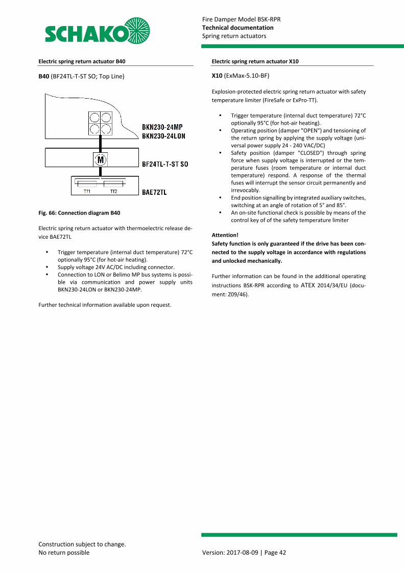
Fire Damper Model BSK-RPR Technical documentation Spring return actuators
Construction subject to change. No return possible Version: 2017-08-09 | Page 42
Electric spring return actuator B40
B40 (BF24TL-T-ST SO; Top Line)
Fig. 66: Connection diagram B40
Electric spring return actuator with thermoelectric release de-vice BAE72TL
Trigger temperature (internal duct temperature) 72°C optionally 95°C (for hot-air heating).
Supply voltage 24V AC/DC including connector. Connection to LON or Belimo MP bus systems is possi-
ble via communication and power supply units BKN230-24LON or BKN230-24MP.
Further technical information available upon request.
Electric spring return actuator X10
X10 (ExMax-5.10-BF)
Explosion-protected electric spring return actuator with safety temperature limiter (FireSafe or ExPro-TT).
Trigger temperature (internal duct temperature) 72°C optionally 95°C (for hot-air heating).
Operating position (damper "OPEN") and tensioning of the return spring by applying the supply voltage (uni-versal power supply 24 - 240 VAC/DC)
Safety position (damper "CLOSED") through spring force when supply voltage is interrupted or the tem-perature fuses (room temperature or internal duct temperature) respond. A response of the thermal fuses will interrupt the sensor circuit permanently and irrevocably.
End position signalling by integrated auxiliary switches, switching at an angle of rotation of 5° and 85°.
An on-site functional check is possible by means of the control key of of the safety temperature limiter
Attention! Safety function is only guaranteed if the drive has been con-nected to the supply voltage in accordance with regulations and unlocked mechanically.
Further information can be found in the additional operating instructions BSK-RPR according to ATEX 2014/34/EU (docu-ment: Z09/46).
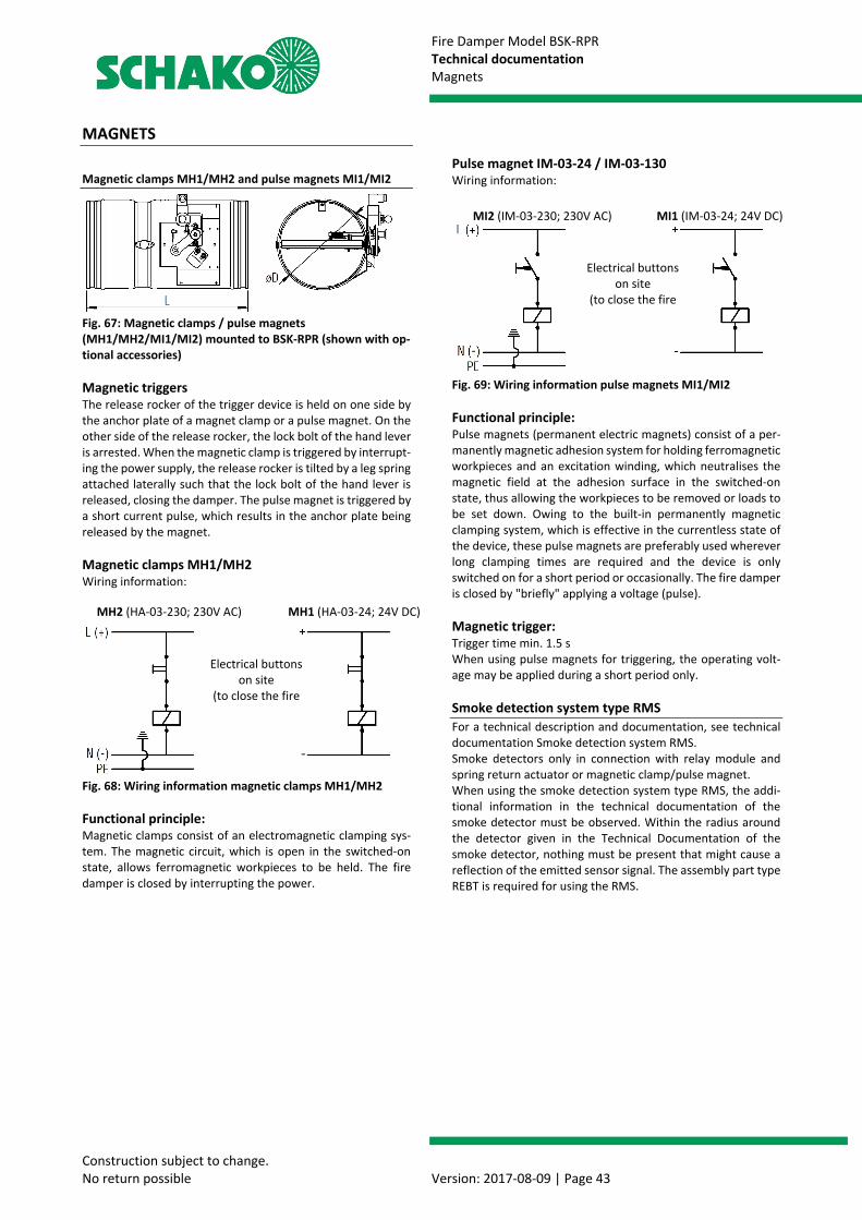
Fire Damper Model BSK-RPR Technical documentation Magnets
Construction subject to change. No return possible Version: 2017-08-09 | Page 43
MAGNETS
Magnetic clamps MH1/MH2 and pulse magnets MI1/MI2
Fig. 67: Magnetic clamps / pulse magnets (MH1/MH2/MI1/MI2) mounted to BSK-RPR (shown with op-tional accessories) Magnetic triggers The release rocker of the trigger device is held on one side by the anchor plate of a magnet clamp or a pulse magnet. On the other side of the release rocker, the lock bolt of the hand lever is arrested. When the magnetic clamp is triggered by interrupt-ing the power supply, the release rocker is tilted by a leg spring attached laterally such that the lock bolt of the hand lever is released, closing the damper. The pulse magnet is triggered by a short current pulse, which results in the anchor plate being released by the magnet. Magnetic clamps MH1/MH2 Wiring information:
Fig. 68: Wiring information magnetic clamps MH1/MH2 Functional principle: Magnetic clamps consist of an electromagnetic clamping sys-tem. The magnetic circuit, which is open in the switched-on state, allows ferromagnetic workpieces to be held. The fire damper is closed by interrupting the power.
Pulse magnet IM-03-24 / IM-03-130 Wiring information:
Fig. 69: Wiring information pulse magnets MI1/MI2 Functional principle: Pulse magnets (permanent electric magnets) consist of a per-manently magnetic adhesion system for holding ferromagnetic workpieces and an excitation winding, which neutralises the magnetic field at the adhesion surface in the switched-on state, thus allowing the workpieces to be removed or loads to be set down. Owing to the built-in permanently magnetic clamping system, which is effective in the currentless state of the device, these pulse magnets are preferably used wherever long clamping times are required and the device is only switched on for a short period or occasionally. The fire damper is closed by "briefly" applying a voltage (pulse). Magnetic trigger: Trigger time min. 1.5 s When using pulse magnets for triggering, the operating volt-age may be applied during a short period only. Smoke detection system type RMS For a technical description and documentation, see technical documentation Smoke detection system RMS. Smoke detectors only in connection with relay module and spring return actuator or magnetic clamp/pulse magnet. When using the smoke detection system type RMS, the addi-tional information in the technical documentation of the smoke detector must be observed. Within the radius around the detector given in the Technical Documentation of the smoke detector, nothing must be present that might cause a reflection of the emitted sensor signal. The assembly part type REBT is required for using the RMS.
MH2 (HA-03-230; 230V AC) MH1 (HA-03-24; 24V DC)
Electrical buttons on site
(to close the fire
MI2 (IM-03-230; 230V AC) MI1 (IM-03-24; 24V DC)
Electrical buttons on site
(to close the fire
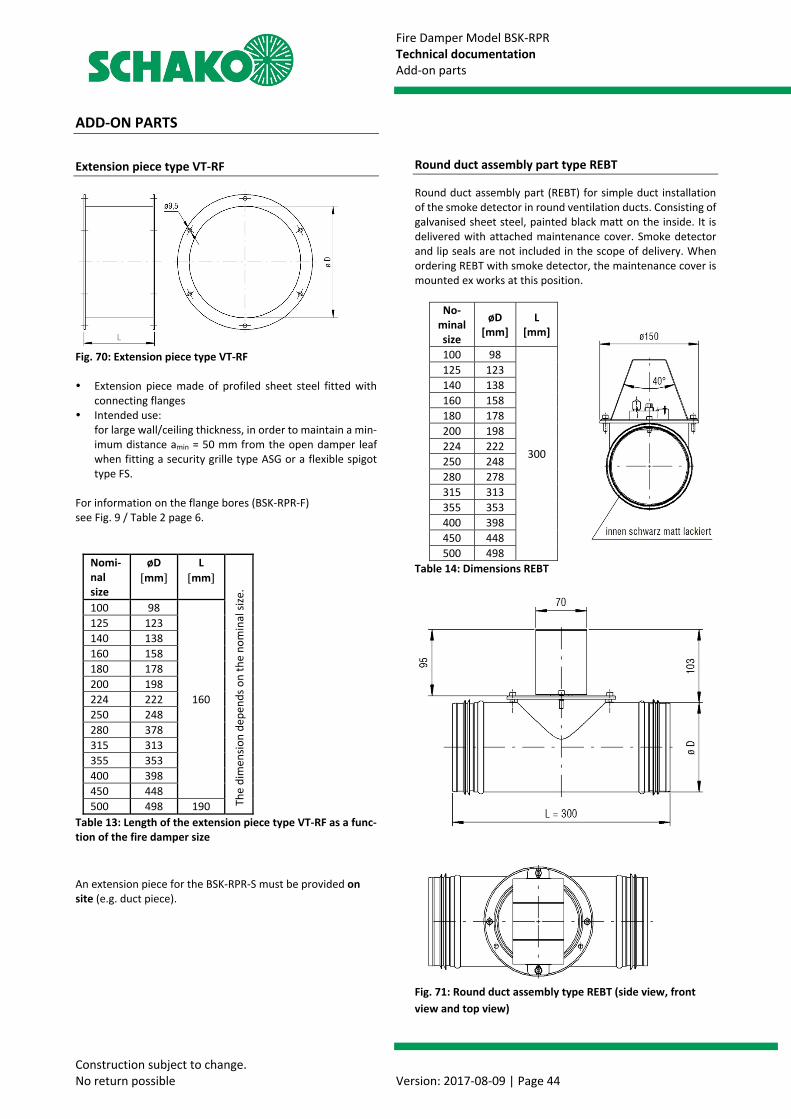
Fire Damper Model BSK-RPR Technical documentation Add-on parts
Construction subject to change. No return possible Version: 2017-08-09 | Page 44
ADD-ON PARTS
Extension piece type VT-RF
Fig. 70: Extension piece type VT-RF Extension piece made of profiled sheet steel fitted with
connecting flanges Intended use:
for large wall/ceiling thickness, in order to maintain a min-imum distance amin = 50 mm from the open damper leaf when fitting a security grille type ASG or a flexible spigot type FS.
For information on the flange bores (BSK-RPR-F) see Fig. 9 / Table 2 page 6.
Nomi-nal size
øD [mm]
L [mm]
The
dim
ensio
n de
pend
s on
the
nom
inal
size
.
100 98
160
125 123 140 138 160 158 180 178 200 198 224 222 250 248 280 378 315 313 355 353 400 398 450 448 500 498 190
Table 13: Length of the extension piece type VT-RF as a func-tion of the fire damper size An extension piece for the BSK-RPR-S must be provided on site (e.g. duct piece).
Round duct assembly part type REBT
Round duct assembly part (REBT) for simple duct installation of the smoke detector in round ventilation ducts. Consisting of galvanised sheet steel, painted black matt on the inside. It is delivered with attached maintenance cover. Smoke detector and lip seals are not included in the scope of delivery. When ordering REBT with smoke detector, the maintenance cover is mounted ex works at this position.
No-minal size
øD [mm]
L [mm]
100 98
300
125 123 140 138 160 158 180 178 200 198 224 222 250 248 280 278 315 313 355 353 400 398 450 448 500 498
Table 14: Dimensions REBT
Fig. 71: Round duct assembly type REBT (side view, front view and top view)

Fire Damper Model BSK-RPR Technical documentation Add-on parts
Construction subject to change. No return possible Version: 2017-08-09 | Page 45
Flexible spigot type FS-RS/-RF FS-RS
Fig. 72: Flexible spigot type FS-RS FS-RF For information on the flange bores (BSK-RPR-F) see Fig. 9 / Table 2 page 6 .
Fig. 73: Flexible spigot type FS-RF Flexible spigot, consisting of profiled connection flanges
(galvanised sheet steel for FS-RF) or without profiled con-nection flanges (FS-RS) with elastic intermediate piece made of polyester fabric PVC-coated on both sides, nor-mally inflammable to EN 13501-1, with welded lip seals (tightness class C to EN 13180 / EN 1507; temperature-re-sistant from -20°C to +80°C). The flexible part of the spigot (polyester fabric) must have a minimum length Lmin of 100 mm when mounted, resulting in an installation dimension of approx. L = 160 mm for type FS-RF and an installation dimension of approx. L = 190 mm for type FS-RS.
The required equipotential bonding must be executed on site according to the local or national regulations (in Ger-many, for example, VDE regulations). The fire dampers must not be subject to mechanical stress under any cir-cumstances.
Intended use: To prevent built-in fire dampers or space-enclosing com-ponents from being subject to inadmissible forces even in case of fire. The local regulations regarding ventilation sys-tems apply. In addition, flexible spigots must be mounted in the following mounting situations:
• Flexible spigot required on both sides when mounting:
• in solid walls according to EN 1996 or DIN 1053 when dwall < 100 mm
• with and without mounting frame AR on or in light-weight partition walls with metal posts and panelling on both sides according to classification to EN 13501-2 or comparable national standards.
• with and without mounting frame AR on or in light-weight partition walls with metal posts and panelling on one side according to classification to EN 13501-2 or comparable national standards.
• Flexible spigot on one side when mounting: • away from solid walls
Alternatively, flexible ventilation ducts made of aluminium can be connected instead of the flexible spigot.
Flexible spigot must be installed in the scrapped state. This may reduce the free cross section. An extension piece may be necessary.
Duct connection spigot type RS
Fig. 74: Duct connection spigot type RS Duct connection spigot with galvanised sheet steel joining
plate Intended use:
For connection to rectangular ducts further dimensions on request
B x H øD 200x200 98 - 198 225x225 223 250x250 248 325x325 278 - 313 375x375 353 400x400 398 450x450 448 500x500 498
Equipotential bon-ding
(on site)
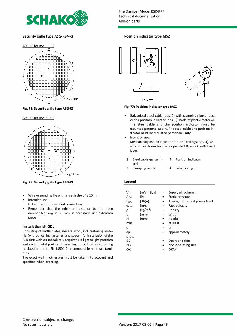
Fire Damper Model BSK-RPR Technical documentation Add-on parts
Construction subject to change. No return possible Version: 2017-08-09 | Page 46
Security grille type ASG-RS/-RF ASG-RS for BSK-RPR-S
Fig. 75: Security grille type ASG-RS ASG-RF for BSK-RPR-F
Fig. 76: Security grille type ASG-RF Wire or punch grille with a mesh size of ≤ 20 mm Intended use:
to be fitted for one-sided connection Remember that the minimum distance to the open
damper leaf amin is 50 mm, if necessary, use extension piece
Installation kit GDL Consisting of baffle plates, mineral wool, incl. fastening mate-rial (without ceiling fastener) and spacer, for installation of the BSK-RPR with AR (absolutely required) in lightweight partition walls with metal posts and panelling on both sides according to classification to EN 13501-2 or comparable national stand-ards. The exact wall thickness/es must be taken into account and specified when ordering.
Position indicator type MSZ
Fig. 77: Position indicator type MSZ Galvanised steel cable (pos. 1) with clamping nipple (pos.
2) and position indicator (pos. 3) made of plastic material. The steel cable and the position indicator must be mounted perpendicularly. The steel cable and position in-dicator must be mounted perpendicularly.
Intended use: Mechanical position indicator for false ceilings (pos. 4). Us-able for each mechanically operated BSK-RPR with hand lever.
1 Steel cable -galvani-
sed- 3 Position indicator
2 Clamping nipple 4 False ceilings Legend
VZU (m³/h) [l/s] = Supply air volume Δpst (Pa) = Static pressure LWA [dB(A)] = A-weighted sound power level vstirn (m/s) = Face velocity ρ (kg/m³) = Density B (mm) = Width H (mm) = Height min. = at least or = or ap-prox.
= approximately
BS = Operating side NBS = Non-operating side OK = OKAY

Fire Damper Model BSK-RPR Technical documentation CE marking
Construction subject to change. No return possible Version: 2017-08-09 | Page 47
CE MARKING
12
0761
SCHAKO Klima-Luft Ferdinand Schad KG
Weidenäcker 9 D-88605 Meßkirch
2013
DoP-BSK-RPR-2017-08-09
EN 15650:2010
Fire Damper
Type/version
BSK-RPR
Nominal conditions of activation / sensitivity: - Load bearing capacity of the temperature-sensitive measuring sensor - Response temperature of the temperature-sensitive measuring sensor
passed
Response delay (Response time): - Closing time
passed
Operational safety: - Cyclic testing (50 cycles) passed
Fire resistance: - Cross-section maintained - Integrity E - Heat insulation I - Smoke leakage S - Mechanical strength (under E) - Cross-section (under E)
EI 90 (ve, ho, i↔o) S
Durability of the response delay: - temperature-sensitive measuring sensor Response temperature and load bearing capacity
Durability of the operational safety: - Test of the opening and closing cycle
passed
passed
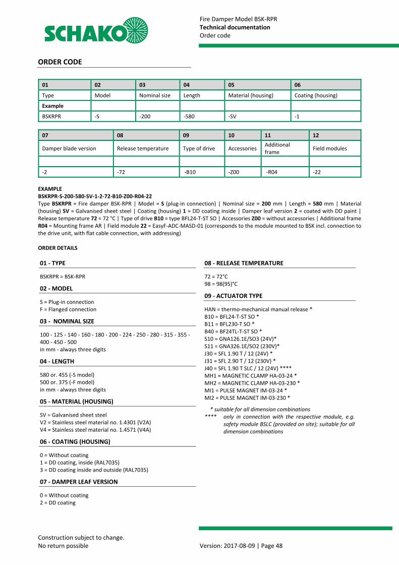
Fire Damper Model BSK-RPR Technical documentation Order code
Construction subject to change. No return possible Version: 2017-08-09 | Page 48
ORDER CODE
01 02 03 04 05 06
Type Model Nominal size Length Material (housing) Coating (housing)
Example
BSKRPR -S -200 -580 -SV -1
07 08 09 10 11 12
Damper blade version Release temperature Type of drive Accessories Additional frame Field modules
-2 -72 -B10 -Z00 -R04 -22 EXAMPLE BSKRPR-S-200-580-SV-1-2-72-B10-Z00-R04-22 Type BSKRPR = Fire damper BSK-RPR | Model = S (plug-in connection) | Nominal size = 200 mm | Length = 580 mm | Material (housing) SV = Galvanised sheet steel | Coating (housing) 1 = DD coating inside | Damper leaf version 2 = coated with DD paint | Release temperature 72 = 72 °C | Type of drive B10 = type BFL24-T-ST SO | Accessories Z00 = without accessories | Additional frame R04 = Mounting frame AR | Field module 22 = EasyF-ADC-MASD-01 (corresponds to the module mounted to BSK incl. connection to the drive unit, with flat cable connection, with addressing) ORDER DETAILS 01 - TYPE
BSKRPR = BSK-RPR
02 - MODEL
S = Plug-in connection F = Flanged connection
03 - NOMINAL SIZE
100 - 125 - 140 - 160 - 180 - 200 - 224 - 250 - 280 - 315 - 355 - 400 - 450 - 500 in mm - always three digits
04 - LENGTH
580 or. 455 (-S model) 500 or. 375 (-F model) in mm - always three digits
05 - MATERIAL (HOUSING)
SV = Galvanised sheet steel V2 = Stainless steel material no. 1.4301 (V2A) V4 = Stainless steel material no. 1.4571 (V4A)
06 - COATING (HOUSING)
0 = Without coating 1 = DD coating, inside (RAL7035) 3 = DD coating inside and outside (RAL7035)
07 - DAMPER LEAF VERSION
0 = Without coating 2 = DD coating
08 - RELEASE TEMPERATURE
72 = 72°C 98 = 98(95)°C
09 - ACTUATOR TYPE
HAN = thermo-mechanical manual release * B10 = BFL24-T-ST SO * B11 = BFL230-T SO * B40 = BF24TL-T-ST SO * S10 = GNA126.1E/SO3 (24V)* S11 = GNA326.1E/SO2 (230V)* J30 = SFL 1.90 T / 12 (24V) * J31 = SFL 2.90 T / 12 (230V) * J40 = SFL 1.90 T SLC / 12 (24V) **** MH1 = MAGNETIC CLAMP HA-03-24 * MH2 = MAGNETIC CLAMP HA-03-230 * MI1 = PULSE MAGNET IM-03-24 * MI2 = PULSE MAGNET IM-03-230 *
* suitable for all dimension combinations **** only in connection with the respective module, e.g.
safety module BSLC (provided on site); suitable for all dimension combinations
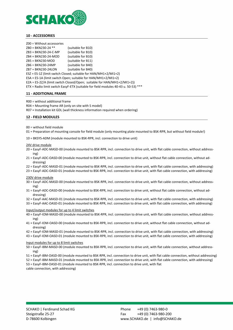
SCHAKO | Ferdinand Schad KG Phone +49 (0) 7463-980-0 Steigstraße 25-27 Fax +49 (0) 7463-980-200 D-78600 Kolbingen www.SCHAKO.de | [email protected]
10 - ACCESSORIES
Z00 = Without accessories ZB0 = BKN230-24 ** (suitable for B10) ZB3 = BKN230-24-C-MP (suitable for B10) ZB4 = BKN230-24-MOD (suitable for B10) ZB5 = BKN230-MOD (suitable for B11) ZB6 = BKN230-24MP (suitable for B40) ZB7 = BKN230-24LON (suitable for B40) ESZ = ES-1Z (limit switch Closed; suitable for HAN/MH1+2/MI1+2) ESA = ES-1A (limit switch Open; suitable for HAN/MH1+2/MI1+2) EZA = ES-2Z/A (limit switch Closed/Open; suitable for HAN/MH1+2/MI1+2)) ETX = Radio limit switch EasyF-ETX (suitable for field modules 40-43 u. 50-53) ***
11 - ADDITIONAL FRAME
R00 = without additional frame R04 = Mounting frame AR (only on site with S model) R07 = Installation kit GDL (wall thickness information required when ordering)
12 - FIELD MODULES
00 = without field module 01 = Preparation of mounting console for field module (only mounting plate mounted to BSK-RPR, but without field module!)
10 = BKSYS-ADM (module mounted to BSK-RPR, incl. connection to drive unit)
24V drive module 20 = EasyF-ADC-MASD-00 (module mounted to BSK-RPR, incl. connection to drive unit, with flat cable connection, without address-
ing) 21 = EasyF-ADC-OASD-00 (module mounted to BSK-RPR, incl. connection to drive unit, without flat cable connection, without ad-
dressing) 22 = EasyF-ADC-MASD-01 (module mounted to BSK-RPR, incl. connection to drive unit, with flat cable connection, with addressing) 23 = EasyF-ADC-OASD-01 (module mounted to BSK-RPR, incl. connection to drive unit, with flat cable connection, with addressing)
230V drive module 30 = EasyF-ADC-MASD-00 (module mounted to BSK-RPR, incl. connection to drive unit, with flat cable connection, without address-
ing) 31 = EasyF-ADC-OASD-00 (module mounted to BSK-RPR, incl. connection to drive unit, without flat cable connection, without ad-
dressing) 32 = EasyF-AAC-MASD-01 (module mounted to BSK-RPR, incl. connection to drive unit, with flat cable connection, with addressing) 33 = EasyF-AAC-OASD-01 (module mounted to BSK-RPR, incl. connection to drive unit, with flat cable connection, with addressing)
Input/output modules for up to 4 limit switches 40 = EasyF-IOM-MASD-00 (module mounted to BSK-RPR, incl. connection to drive unit, with flat cable connection, without address-
ing) 41 = EasyF-IOM-OASD-00 (module mounted to BSK-RPR, incl. connection to drive unit, without flat cable connection, without ad-
dressing) 42 = EasyF-IOM-MASD-01 (module mounted to BSK-RPR, incl. connection to drive unit, with flat cable connection, with addressing) 43 = EasyF-IOM-OASD-01 (module mounted to BSK-RPR, incl. connection to drive unit, with flat cable connection, with addressing)
Input modules for up to 8 limit switches 50 = EasyF-I8M-MASD-00 (module mounted to BSK-RPR, incl. connection to drive unit, with flat cable connection, without address-
ing) 51 = EasyF-I8M-OASD-00 (module mounted to BSK-RPR, incl. connection to drive unit, with flat cable connection, without addressing) 52 = EasyF-I8M-MASD-01 (module mounted to BSK-RPR, incl. connection to drive unit, with flat cable connection, with addressing) 53 = EasyF-I8M-OASD-01 (module mounted to BSK-RPR, incl. connection to drive unit, with flat cable connection, with addressing)

Fire Damper Model BSK-RPR Technical documentation Specification texts
Construction subject to change. No return possible Version: 2017-08-09 | Page 50
SPECIFICATION TEXTS The fire damper BSK-RPR corresponds to EN 15650, EN 13501-3 and EN 1366-2. The fire damper BSK-RPR has been tested according to EN 1366-2 in accordance with the Declaration of Performance no. DoP-BSK-RPR-2017-08-09. It has the certificate of consistency of performance according to EU-Bau PVO 0761-CPR-0245 and the EC Certificate of Con-formity 0761-CPD-0263. Its classification according to EN 13501-3 is EI 90 (ve, ho i↔o) S. According to Directive 2014/34/EU, EC Certificate of Conform-ity Number EPS 09 ATEX 2 153 X, its use in areas subject to ex-plosion hazards is permitted, not only with spring return actu-ator X10 (ExMax-5.10-BF), including safety temperature limiter (FireSafe or ExPro-TT), but also with mechanical trigger via fu-sible link (manual actuation with or without ATEX limit switch ES-Ex). The fire damper is marked as follows according to ATEX:
II 2 G IIC T6 II 2D T80°C II 3 D T80°C*)
EPS 09 ATEX 2 153 X
*) when using the safety temperature limiter FireSafe. Housing made of galvanised sheet steel, with moulded-on plug-in connections (model -S) or with connection flanges to EN 12220 or DIN 24154-1 (model -F) Damper leaf made of abrasion-resistant, mineral silicate boards. Wear-resistant elastomer seal on the damper leaf and intumescent seal on the housing to meet the cold and hot leakage requirements according to EN 1366-2. Any accessories that may be required for the respective mounting situation (flexible spigots, suspensions, pole braces, etc.) are listed in separate positions of the specification. For connection to ventilation ducts (one- or two-sided), air flow direction optional. Connection to smoke detectors with general building supervi-sory approval possible. When using the smoke detection system type RMS, the addi-tional information in the technical documentation of the smoke detector must be observed. Installation: in solid walls and solid ceilings in connection with a mounting frame AR on solid walls and
solid ceilings (directly on/under) in connection with a mounting frame AR away from solid
walls Installation in lightweight partition walls with metal posts
and panelling on both sides according to EN 13501-2 or comparable national stand-ards (wet installation)
with mounting frame AR on lightweight partition walls with metal posts and panelling on both sides according to classification to EN 13501-2 or comparable national standards.
with mounting frame AR on lightweight partition walls with metal posts and panelling on both sides according to classification to EN 13501-2 or comparable national standards, in the area of sliding ceiling connections
in lightweight partition walls (F30) with metal posts and panelling on both sides according to classification to EN 13501-2 or comparable national standards (nominal sizes 100 - 250)
in lightweight partition walls with metal posts and panel-ling on one side according to classification to EN 13501-2 or comparable national standards. (nominal sizes 100 - 250)
with mounting frame AR on lightweight partition walls with metal posts and panelling on one side according to classification to EN 13501-2 or comparable national standards.
Product: SCHAKO type BSK-RPR Declaration of Performance no. DoP-BSK-RPR-2017-08-09
Dimensions: Diameter: .................... mm Length (L): 455/580 mm (-S model) 375/500 mm (-F model) (Unless stated otherwise, the mechanical -S model (plug-in connection), length 580 mm and fusible link release tempera-ture 72°C will be delivered)
Alternative models or accessories (at an extra charge) ("Select as desired") Model with mounting frame AR (mounting exclusively ex
works and for "S" model) Model made of stainless steel material no. 1.4301 (V2A) Model made of stainless steel material no. 1.4571 (V4A) Housing with DD coating (solvent-containing two-compo-
nent top coat based on polyurethane varnish - RAL 7035 / light-grey) DD coating, inside/outside
Model for sliding ceiling connection (BSK-RPR-S, L=580, with mounting frame AR and accessories)
Thermal release with mechanical fusible link release tem-perature 98°C (for hot-air heating)
Model marked according to ATEX
Electric limit switch for "OPEN" and/or "CLOSED" position indicators, switching element containing one NC and one NO contact: ESZ (type ES 1Z: "CLOSED") ESA (type ES 1A: "OPEN") EZA (type ES 2: "OPEN" and "CLOSED")
Limit switch type ES-Ex for "OPEN" or/and "CLOSED" posi-tion indicators, application in areas subject to explosion hazards: Type ES EX 1Z: "CLOSED" Type ES EX 1A: "OPEN" Type ES EX 2: "OPEN" and "CLOSED"
Limit switch ETX (type EasyF-ETX), for connection to SCHAKO signalling and switching bus system EasyBus, the status of the damper position being transferred by radio signal. Additional radio receiver EasyF-RXE required.
Electric spring return actuator with thermoelectric release
device BAT (B10/B11) or temperature monitoring unit (S10/S11). Releases at a room temperature of 72°C and an inter-
nal duct temperature of 72°C (optionally: 95°C) con-taining integrated micro switches/auxiliary switches for indication of damper end positions (24 V drive, in-cluding connector):
o Type B10 (BFL24-T-ST SO) or B11 (BFL230-T SO)
o Type S10 (GNA126.1E/SO3) or S11 (GNA326.1E/SO2)
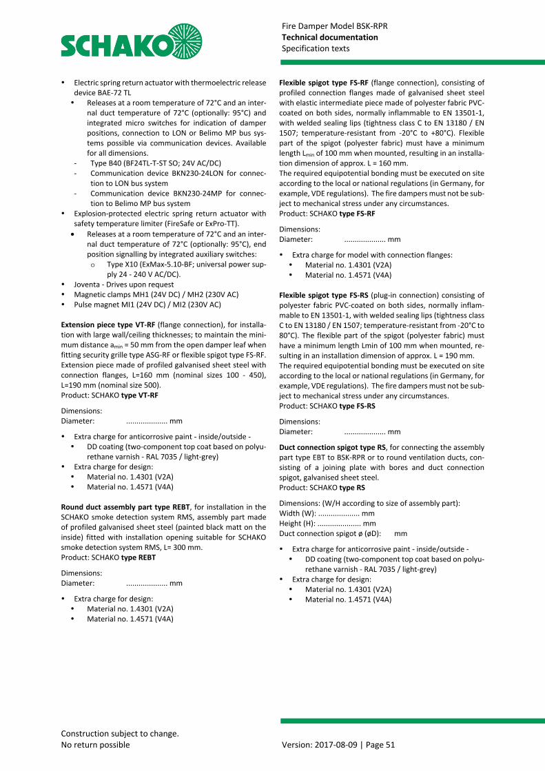
Fire Damper Model BSK-RPR Technical documentation Specification texts
Construction subject to change. No return possible Version: 2017-08-09 | Page 51
Electric spring return actuator with thermoelectric release device BAE-72 TL Releases at a room temperature of 72°C and an inter-
nal duct temperature of 72°C (optionally: 95°C) and integrated micro switches for indication of damper positions, connection to LON or Belimo MP bus sys-tems possible via communication devices. Available for all dimensions.
- Type B40 (BF24TL-T-ST SO; 24V AC/DC) - Communication device BKN230-24LON for connec-
tion to LON bus system - Communication device BKN230-24MP for connec-
tion to Belimo MP bus system Explosion-protected electric spring return actuator with
safety temperature limiter (FireSafe or ExPro-TT). • Releases at a room temperature of 72°C and an inter-
nal duct temperature of 72°C (optionally: 95°C), end position signalling by integrated auxiliary switches: o Type X10 (ExMax-5.10-BF; universal power sup-
ply 24 - 240 V AC/DC). Joventa - Drives upon request Magnetic clamps MH1 (24V DC) / MH2 (230V AC) Pulse magnet MI1 (24V DC) / MI2 (230V AC) Extension piece type VT-RF (flange connection), for installa-tion with large wall/ceiling thicknesses; to maintain the mini-mum distance amin = 50 mm from the open damper leaf when fitting security grille type ASG-RF or flexible spigot type FS-RF. Extension piece made of profiled galvanised sheet steel with connection flanges, L=160 mm (nominal sizes 100 - 450), L=190 mm (nominal size 500). Product: SCHAKO type VT-RF
Dimensions: Diameter: .................... mm
Extra charge for anticorrosive paint - inside/outside - DD coating (two-component top coat based on polyu-
rethane varnish - RAL 7035 / light-grey) Extra charge for design: Material no. 1.4301 (V2A) Material no. 1.4571 (V4A)
Round duct assembly part type REBT, for installation in the SCHAKO smoke detection system RMS, assembly part made of profiled galvanised sheet steel (painted black matt on the inside) fitted with installation opening suitable for SCHAKO smoke detection system RMS, L= 300 mm. Product: SCHAKO type REBT
Dimensions: Diameter: .................... mm
Extra charge for design: Material no. 1.4301 (V2A) Material no. 1.4571 (V4A)
Flexible spigot type FS-RF (flange connection), consisting of profiled connection flanges made of galvanised sheet steel with elastic intermediate piece made of polyester fabric PVC-coated on both sides, normally inflammable to EN 13501-1, with welded sealing lips (tightness class C to EN 13180 / EN 1507; temperature-resistant from -20°C to +80°C). Flexible part of the spigot (polyester fabric) must have a minimum length Lmin of 100 mm when mounted, resulting in an installa-tion dimension of approx. L = 160 mm. The required equipotential bonding must be executed on site according to the local or national regulations (in Germany, for example, VDE regulations). The fire dampers must not be sub-ject to mechanical stress under any circumstances. Product: SCHAKO type FS-RF
Dimensions: Diameter: .................... mm
Extra charge for model with connection flanges: Material no. 1.4301 (V2A) Material no. 1.4571 (V4A)
Flexible spigot type FS-RS (plug-in connection) consisting of polyester fabric PVC-coated on both sides, normally inflam-mable to EN 13501-1, with welded sealing lips (tightness class C to EN 13180 / EN 1507; temperature-resistant from -20°C to 80°C). The flexible part of the spigot (polyester fabric) must have a minimum length Lmin of 100 mm when mounted, re-sulting in an installation dimension of approx. L = 190 mm. The required equipotential bonding must be executed on site according to the local or national regulations (in Germany, for example, VDE regulations). The fire dampers must not be sub-ject to mechanical stress under any circumstances. Product: SCHAKO type FS-RS
Dimensions: Diameter: .................... mm
Duct connection spigot type RS, for connecting the assembly part type EBT to BSK-RPR or to round ventilation ducts, con-sisting of a joining plate with bores and duct connection spigot, galvanised sheet steel. Product: SCHAKO type RS
Dimensions: (W/H according to size of assembly part): Width (W): .................... mm Height (H): ..................... mm Duct connection spigot ø (øD): mm
Extra charge for anticorrosive paint - inside/outside - DD coating (two-component top coat based on polyu-
rethane varnish - RAL 7035 / light-grey) Extra charge for design: Material no. 1.4301 (V2A) Material no. 1.4571 (V4A)
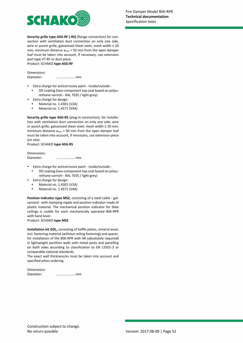
Fire Damper Model BSK-RPR Technical documentation Specification texts
Construction subject to change. No return possible Version: 2017-08-09 | Page 52
Security grille type ASG-RF (-RS) (flange connection) for con-nection with ventilation duct connection on only one side, wire or punch grille, galvanised sheet steel, mesh width ≤ 20 mm, minimum distance amin = 50 mm from the open damper leaf must be taken into account, if necessary, use extension part type VT-RF or duct piece. Product: SCHAKO type ASG-RF Dimensions: Diameter: .................... mm Extra charge for anticorrosive paint - inside/outside - DD coating (two-component top coat based on polyu-
rethane varnish - RAL 7035 / light-grey) Extra charge for design: Material no. 1.4301 (V2A) Material no. 1.4571 (V4A)
Security grille type ASG-RS (plug-in connection), for installa-tion with ventilation duct connection on only one side, wire or punch grille, galvanised sheet steel, mesh width ≤ 20 mm, minimum distance amin = 50 mm from the open damper leaf must be taken into account, if necessary, use extension piece (on site). Product: SCHAKO type ASG-RS Dimensions: Diameter: .................... mm Extra charge for anticorrosive paint - inside/outside - DD coating (two-component top coat based on polyu-
rethane varnish - RAL 7035 / light-grey) Extra charge for design: Material no. 1.4301 (V2A) Material no. 1.4571 (V4A)
Position indicator type MSZ, consisting of a steel cable - gal-vanised - with clamping nipple and position indicator made of plastic material. The mechanical position indicator for false ceilings is usable for each mechanically operated BSK-RPR with hand lever. Product: SCHAKO type MSZ Installation kit GDL, consisting of baffle plates, mineral wool, incl. fastening material (without ceiling fastening) and spacer, for installation of the BSK-RPR with AR (absolutely required) in lightweight partition walls with metal posts and panelling on both sides according to classification to EN 13501-2 or comparable national standards. The exact wall thickness/es must be taken into account and specified when ordering. Dimensions: Diameter: .................... mm

Fire Damper Model BSK-RPR Technical documentation Service
Construction subject to change. No return possible Version: 2017-08-09 | Page 53
SERVICE CHECKING THE FUNCTION, CLEANING, REPAIR
Polluted and damp air can impair the continuous operational safety. Therefore, after commissioning of the ventilation in-stallation, the function of all fire dampers must be checked semi-annually. If two consecutive functional checks do not show any defects, the fire dampers only have to be tested once a year. If mainte-nance are made for ventilation systems, it is recommended including the functional checks of the fire dampers in these agreements. Information on explosion-protected release devices can be found in the additional operating instructions according to ATEX 2014/34/EU (document: Z09/46). 1. Manual trigger device 1.1. Visual inspection Check the fire damper for damage and contamination
(e.g. housing, damper blade, seals). Perform necessary cleaning work 1.2 Manual release – Closing the fire damper Pull manual unlocking disc (pos. 1) at the hand lever (pos.
2), this removes the locking (in the open position) of the locking bolt (pos. 4) in the release device (pos. 3).
Hand lever has been released and is moved toward the closed position by spring force.
ATTENTION! Do not reach into the pivoting range of the damper blade and of the manual lever. There is a risk of in-jury. The fire damper must close and lock automatically (lock-
ing of the damper blade in the closed position). 1.3 Opening the fire damper Pull manual unlocking disc (pos. 1) at the hand lever (pos.
2) and move it toward the release device (pos. 3) Locking bolt (pos. 4) must snap into the release device
(pos. 3). The fire damper is ready for operation again. (Damper
blade is locked in the open position). S = Lubricate moving parts (bearing) only if they are not run-ning smoothly (lubricant: free of resin and acid).
When the fusible link becomes damaged, its replacement must be carried out as follows. If, for example, the fusible link is damaged or corroded, it
is must be replaced. Perform manual release as described in section 1.2. Unscrew the fastening screws (2 pieces, pos.5), pull the
release device out by turning it 90° and remove it from the housing.
Compress the locating pins of the fusible link holder (pos. 6) using a suitable tool (e.g. pliers) and replace the fusible link with a replacement fusible link (pos. 7).
Insert the release device and fasten it with screws (make sure that the position of the coding screw with regard to the coding hole is correct).
Finally a functional check has to be carried out. BSK-RPR with manual release
Fig. 78: Side view BSK-RPR (manual release)
Fig. 79: Front view BSK-RPR (manual release)
Fig. 80: Release device BSK-RPR (fusible link)
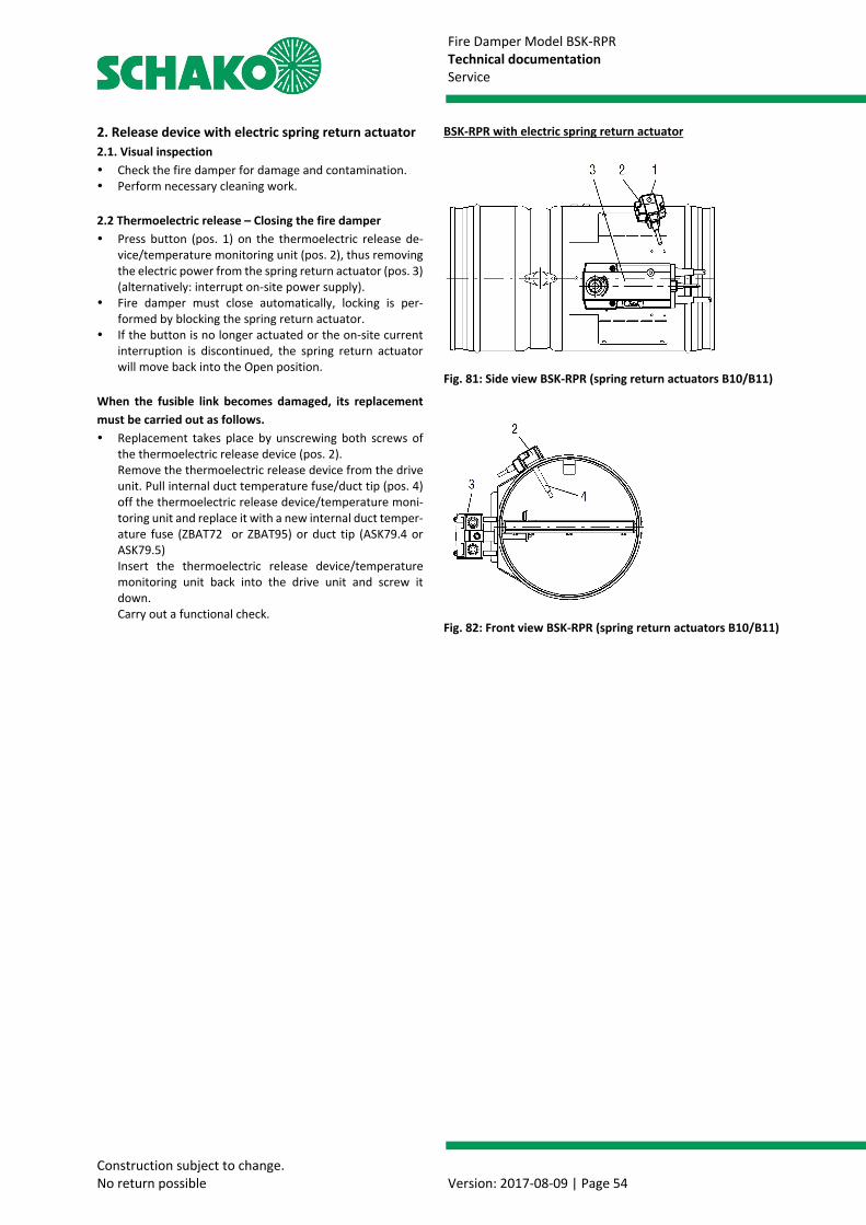
Fire Damper Model BSK-RPR Technical documentation Service
Construction subject to change. No return possible Version: 2017-08-09 | Page 54
2. Release device with electric spring return actuator 2.1. Visual inspection Check the fire damper for damage and contamination. Perform necessary cleaning work. 2.2 Thermoelectric release – Closing the fire damper Press button (pos. 1) on the thermoelectric release de-
vice/temperature monitoring unit (pos. 2), thus removing the electric power from the spring return actuator (pos. 3) (alternatively: interrupt on-site power supply).
Fire damper must close automatically, locking is per-formed by blocking the spring return actuator.
If the button is no longer actuated or the on-site current interruption is discontinued, the spring return actuator will move back into the Open position.
When the fusible link becomes damaged, its replacement must be carried out as follows. Replacement takes place by unscrewing both screws of
the thermoelectric release device (pos. 2). Remove the thermoelectric release device from the drive unit. Pull internal duct temperature fuse/duct tip (pos. 4) off the thermoelectric release device/temperature moni-toring unit and replace it with a new internal duct temper-ature fuse (ZBAT72 or ZBAT95) or duct tip (ASK79.4 or ASK79.5) Insert the thermoelectric release device/temperature monitoring unit back into the drive unit and screw it down. Carry out a functional check.
BSK-RPR with electric spring return actuator
Fig. 81: Side view BSK-RPR (spring return actuators B10/B11)
Fig. 82: Front view BSK-RPR (spring return actuators B10/B11)
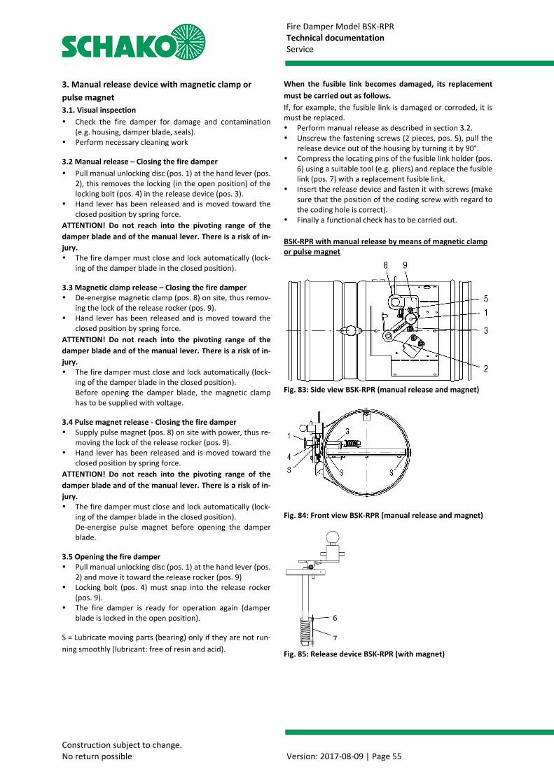
Fire Damper Model BSK-RPR Technical documentation Service
Construction subject to change. No return possible Version: 2017-08-09 | Page 55
3. Manual release device with magnetic clamp or pulse magnet 3.1. Visual inspection Check the fire damper for damage and contamination
(e.g. housing, damper blade, seals). Perform necessary cleaning work 3.2 Manual release – Closing the fire damper Pull manual unlocking disc (pos. 1) at the hand lever (pos.
2), this removes the locking (in the open position) of the locking bolt (pos. 4) in the release device (pos. 3).
Hand lever has been released and is moved toward the closed position by spring force.
ATTENTION! Do not reach into the pivoting range of the damper blade and of the manual lever. There is a risk of in-jury. The fire damper must close and lock automatically (lock-
ing of the damper blade in the closed position). 3.3 Magnetic clamp release – Closing the fire damper De-energise magnetic clamp (pos. 8) on site, thus remov-
ing the lock of the release rocker (pos. 9). Hand lever has been released and is moved toward the
closed position by spring force. ATTENTION! Do not reach into the pivoting range of the damper blade and of the manual lever. There is a risk of in-jury. The fire damper must close and lock automatically (lock-
ing of the damper blade in the closed position). Before opening the damper blade, the magnetic clamp has to be supplied with voltage.
3.4 Pulse magnet release - Closing the fire damper Supply pulse magnet (pos. 8) on site with power, thus re-
moving the lock of the release rocker (pos. 9). Hand lever has been released and is moved toward the
closed position by spring force. ATTENTION! Do not reach into the pivoting range of the damper blade and of the manual lever. There is a risk of in-jury. The fire damper must close and lock automatically (lock-
ing of the damper blade in the closed position). De-energise pulse magnet before opening the damper blade.
3.5 Opening the fire damper Pull manual unlocking disc (pos. 1) at the hand lever (pos.
2) and move it toward the release rocker (pos. 9) Locking bolt (pos. 4) must snap into the release rocker
(pos. 9). The fire damper is ready for operation again (damper
blade is locked in the open position). S = Lubricate moving parts (bearing) only if they are not run-ning smoothly (lubricant: free of resin and acid).
When the fusible link becomes damaged, its replacement must be carried out as follows. If, for example, the fusible link is damaged or corroded, it is must be replaced. Perform manual release as described in section 3.2. Unscrew the fastening screws (2 pieces, pos. 5), pull the
release device out of the housing by turning it by 90°. Compress the locating pins of the fusible link holder (pos.
6) using a suitable tool (e.g. pliers) and replace the fusible link (pos. 7) with a replacement fusible link.
Insert the release device and fasten it with screws (make sure that the position of the coding screw with regard to the coding hole is correct).
Finally a functional check has to be carried out. BSK-RPR with manual release by means of magnetic clamp or pulse magnet
Fig. 83: Side view BSK-RPR (manual release and magnet)
Fig. 84: Front view BSK-RPR (manual release and magnet)
Fig. 85: Release device BSK-RPR (with magnet)
6 7

Fire Damper Model BSK-RPR Technical documentation Service
Construction subject to change. No return possible Version: 2017-08-09 | Page 56
SAMPLE OF FUNCTIONAL CHECK PROTOCOL
SCHAKO Ferdinand Schad KG Steigstrasse 25-27 D-78600 Kolbingen Phone: +49- (0)7463 / 980-0 Fax: +49- (0)7463 / 980-200 E-mail: [email protected]
Web: www.schako.de
Sample Functional check protocol for fire dampers Cons. No. ____________________ Fire damper no.: Declaration of perfor-mance no.: Series: Release device:
The following functional steps have been carried out according to the documents installation, mounting and operating instructions
Prior to commis-sioning
Next functional check in: _____________
Next functional check in: _____________
Next functional check in: _____________
Next functional check in: _____________
External check:
System: _____________________ Item: _______________________ Internal check:
System: _____________________ Item: _______________________ Additional check:
System: _____________________ Item: _______________________
without defects Date / tester
with defects (see back) Date / tester
without defects Date / tester

Fire Damper Model BSK-RPR Technical documentation Service
Construction subject to change. No return possible Version: 2017-08-09 | Page 57
SCHAKO Ferdinand Schad KG Steigstrasse 25-27 D-78600 Kolbingen Phone: +49- (0)7463 / 980-0 Fax: +49- (0)7463 / 980-200 E-mail: [email protected]
Web: www.schako.de
Sample Functional check protocol for fire dampers Cons. No. ____________________ Defects found during the test on: ________________________________________ Sluggishness due to soiling. Any remaining mortar must be removed. Defects found during the test on: ________________________________________ Defects found during the test on: ________________________________________ Defects found during the test on: ________________________________________

Fire Damper Model BSK-RPR Technical documentation Foreign branch offices
Construction subject to change. No return possible Version: 2017-08-09 | Page 58
FOREIGN BRANCH OFFICES Belgium Denmark England France SCHAKO S.A.R.L. Venti AS SCHAKO Ltd. SCHAKO s.a.r.l. 165, rue des Pommiers Banevænget 3 Index House 16 Boulevard de la Croix RousseL-2343 Luxembourg 8362 Hørning St Georges Lane, Ascot F-69001 Lyon Phone: +352 / 403 157 1 Phone: +45 / 86 92 22 66 SL5 7EU Berkshire Phone: +33 / 4 / 78 34 97 34Fax: +352 / 403 157 66 Fax: +45 / 86 92 22 26 Phone: +44 / 13 44 63 63 89 Fax: +33 / 4 / 78 34 97 [email protected] [email protected] Fax: +44 / 13 44 87 46 58 [email protected] www.schako.be www.venti.dk [email protected] www.schako.fr www.schako.co.uk Greece Israel Italy Croatia EUROPERSIS Insupco Industrial Supply Ltd. SCHAKO Italia S.r.l. Intel Trade Odisea Androutsou 2 40 Hayarkon St. Via XXV Aprile, 17 Dr. Ante Mandica 10 GR-56224 Evosmos/Tessaloniki Yavne 811 00 20097 S.Donato Milanese-MI HR-51410 Opatija Phone: +30 / 310 / 68 57 79 Phone: +972 / 8 / 94 20 080 Phone: +39 / 02 / 51 64 02 01 Phone: +385 / 51 741 100Fax: +30 / 310 / 75 76 13 Fax: +972 / 8 / 94 20 311 Fax: +39 / 02 / 51 62 09 46 Fax: +385 / 51 701 [email protected] [email protected] [email protected] [email protected] www.europersis.gr www.insupco.com www.schako.it www.intel-trade.hr Luxembourg Netherlands Austria Poland SCHAKO S.A.R.L. SCHAKO S.A.R.L. SCHAKO Vertriebs GmbH SCHAKO Polska Sp. z o.o165, rue des Pommiers 165, rue des Pommiers Mariahilfer Straße 103/1/TOP 12 ul. Pulawska 38 L-2343 Luxembourg L-2343 Luxembourg A-1060 Wien PL-05-500 Piaseczno Phone: +352 / 403 157 1 Phone: +352 / 403 157 1 Phone: +43 / 1 / 890 24 62 Phone: +48 / 22 / 7263570Fax: +352 / 403 157 66 Fax: +352 / 403 157 66 Fax: +43 / 1 / 890 24 62 50 Fax: +48 / 22 / [email protected] [email protected] [email protected] [email protected] www.schako.lu www.schako-nederland.nl www.schako.at www.schako.pl Romania Sweden Switzerland Serbia & MontenegroSCHAKO Klima Luft SRL EXOTHERM AB SCHAKO Suisse SA TERMOMEHANIKA d.o.o.Str. Elena Caragiani nr.21 Box 60036 Rue Jean-Prouvé 28 Koste Glavinica 2 014212 Bucuresti, 21610 Limhamn 1762 Givisiez RS-11000 BEOGRAD Phone: +40 / 0 / 21 / 232 13 75 Phone: +46 / 40 / 631 61 16 Phone: +41 / 26 / 460 88 00 Phone: +381 / 11 / 369 99 93Fax: +40 / 0 / 21 / 232 13 75 Fax: +46 / 40 / 15 60 95 Fax: +41 / 26 / 460 88 05 Fax: +381 / 11 / 369 09 [email protected] [email protected] [email protected] [email protected] www.exotherm.se www.schako.ch www.termomehanika.rs Slovakia Spain Czech Republic Turkey SCHAKO SK s.r.o. SCHAKO IBERIA S.L. SCHAKO s.r.o. EMO-SCHAKO Klima Modrová 187 Departamento de Ventas Pred Skalkami II. 184/5 Havalandirma 91635 Modrová Pol. Ind. Río Gállego, CZ-10600 Praha 10-Zabehlice San. ve Tic. Ltd. Sti. Phone: +421 / 337 / 774 1843 Calle B, nave 3 Phone: +42 / 02 / 727 680 43 Pursaklar Sanayi Sitesi,Fax: +421 / 337 / 774 1843
50840 San Mateo de Gállego / Zaragoza
Fax: +42 / 02 / 727 693 94 Karacaören Mah.1638.Cad. No:98
[email protected] Phone: +34 / 976 / 531 999 [email protected] 06145 Altindag - Ankarawww.schako.sk Fax: +34 / 976 / 690 709 www.schako.cz Phone: +90 / 312 527 16 05 [email protected] Fax: +90 / 312 527 16 08 www.schako.es [email protected] www.emo-schako.com.tr Hungary SCHAKO Kft. Tó Park 6 H-2045 Törökbálint Phone: +36 / 23 / 445670 Fax: +36 / 23 / 445679 [email protected] www.schako.hu
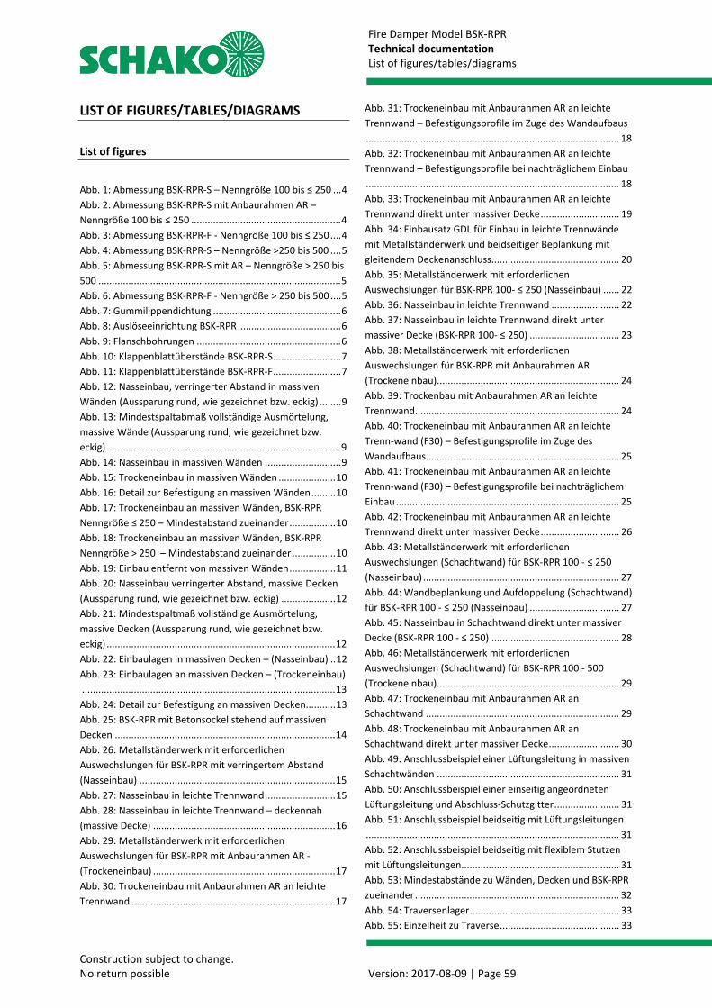
Fire Damper Model BSK-RPR Technical documentation List of figures/tables/diagrams
Construction subject to change. No return possible Version: 2017-08-09 | Page 59
LIST OF FIGURES/TABLES/DIAGRAMS
List of figures
Abb. 1: Abmessung BSK-RPR-S – Nenngröße 100 bis ≤ 250 ... 4 Abb. 2: Abmessung BSK-RPR-S mit Anbaurahmen AR – Nenngröße 100 bis ≤ 250 ....................................................... 4 Abb. 3: Abmessung BSK-RPR-F - Nenngröße 100 bis ≤ 250 .... 4 Abb. 4: Abmessung BSK-RPR-S – Nenngröße >250 bis 500 .... 5 Abb. 5: Abmessung BSK-RPR-S mit AR – Nenngröße > 250 bis 500 ......................................................................................... 5 Abb. 6: Abmessung BSK-RPR-F - Nenngröße > 250 bis 500 .... 5 Abb. 7: Gummilippendichtung ............................................... 6 Abb. 8: Auslöseeinrichtung BSK-RPR ...................................... 6 Abb. 9: Flanschbohrungen ..................................................... 6 Abb. 10: Klappenblattüberstände BSK-RPR-S ......................... 7 Abb. 11: Klappenblattüberstände BSK-RPR-F ......................... 7 Abb. 12: Nasseinbau, verringerter Abstand in massiven Wänden (Aussparung rund, wie gezeichnet bzw. eckig) ........ 9 Abb. 13: Mindestspaltabmaß vollständige Ausmörtelung, massive Wände (Aussparung rund, wie gezeichnet bzw. eckig) ...................................................................................... 9 Abb. 14: Nasseinbau in massiven Wänden ............................ 9 Abb. 15: Trockeneinbau in massiven Wänden ..................... 10 Abb. 16: Detail zur Befestigung an massiven Wänden ......... 10 Abb. 17: Trockeneinbau an massiven Wänden, BSK-RPR Nenngröße ≤ 250 – Mindestabstand zueinander ................. 10 Abb. 18: Trockeneinbau an massiven Wänden, BSK-RPR Nenngröße > 250 – Mindestabstand zueinander ................ 10 Abb. 19: Einbau entfernt von massiven Wänden ................. 11 Abb. 20: Nasseinbau verringerter Abstand, massive Decken (Aussparung rund, wie gezeichnet bzw. eckig) .................... 12 Abb. 21: Mindestspaltmaß vollständige Ausmörtelung, massive Decken (Aussparung rund, wie gezeichnet bzw. eckig) .................................................................................... 12 Abb. 22: Einbaulagen in massiven Decken – (Nasseinbau) .. 12 Abb. 23: Einbaulagen an massiven Decken – (Trockeneinbau) ............................................................................................. 13 Abb. 24: Detail zur Befestigung an massiven Decken........... 13 Abb. 25: BSK-RPR mit Betonsockel stehend auf massiven Decken ................................................................................. 14 Abb. 26: Metallständerwerk mit erforderlichen Auswechslungen für BSK-RPR mit verringertem Abstand (Nasseinbau) ........................................................................ 15 Abb. 27: Nasseinbau in leichte Trennwand .......................... 15 Abb. 28: Nasseinbau in leichte Trennwand – deckennah (massive Decke) ................................................................... 16 Abb. 29: Metallständerwerk mit erforderlichen Auswechslungen für BSK-RPR mit Anbaurahmen AR - (Trockeneinbau) ................................................................... 17 Abb. 30: Trockeneinbau mit Anbaurahmen AR an leichte Trennwand ........................................................................... 17
Abb. 31: Trockeneinbau mit Anbaurahmen AR an leichte Trennwand – Befestigungsprofile im Zuge des Wandaufbaus ............................................................................................. 18 Abb. 32: Trockeneinbau mit Anbaurahmen AR an leichte Trennwand – Befestigungsprofile bei nachträglichem Einbau ............................................................................................. 18 Abb. 33: Trockeneinbau mit Anbaurahmen AR an leichte Trennwand direkt unter massiver Decke ............................. 19 Abb. 34: Einbausatz GDL für Einbau in leichte Trennwände mit Metallständerwerk und beidseitiger Beplankung mit gleitendem Deckenanschluss ............................................... 20 Abb. 35: Metallständerwerk mit erforderlichen Auswechslungen für BSK-RPR 100- ≤ 250 (Nasseinbau) ...... 22 Abb. 36: Nasseinbau in leichte Trennwand ......................... 22 Abb. 37: Nasseinbau in leichte Trennwand direkt unter massiver Decke (BSK-RPR 100- ≤ 250) ................................. 23 Abb. 38: Metallständerwerk mit erforderlichen Auswechslungen für BSK-RPR mit Anbaurahmen AR (Trockeneinbau) ................................................................... 24 Abb. 39: Trockenbau mit Anbaurahmen AR an leichte Trennwand ........................................................................... 24 Abb. 40: Trockeneinbau mit Anbaurahmen AR an leichte Trenn-wand (F30) – Befestigungsprofile im Zuge des Wandaufbaus ....................................................................... 25 Abb. 41: Trockeneinbau mit Anbaurahmen AR an leichte Trenn-wand (F30) – Befestigungsprofile bei nachträglichem Einbau .................................................................................. 25 Abb. 42: Trockeneinbau mit Anbaurahmen AR an leichte Trennwand direkt unter massiver Decke ............................. 26 Abb. 43: Metallständerwerk mit erforderlichen Auswechslungen (Schachtwand) für BSK-RPR 100 - ≤ 250 (Nasseinbau) ........................................................................ 27 Abb. 44: Wandbeplankung und Aufdoppelung (Schachtwand) für BSK-RPR 100 - ≤ 250 (Nasseinbau) ................................. 27 Abb. 45: Nasseinbau in Schachtwand direkt unter massiver Decke (BSK-RPR 100 - ≤ 250) ............................................... 28 Abb. 46: Metallständerwerk mit erforderlichen Auswechslungen (Schachtwand) für BSK-RPR 100 - 500 (Trockeneinbau) ................................................................... 29 Abb. 47: Trockeneinbau mit Anbaurahmen AR an Schachtwand ....................................................................... 29 Abb. 48: Trockeneinbau mit Anbaurahmen AR an Schachtwand direkt unter massiver Decke .......................... 30 Abb. 49: Anschlussbeispiel einer Lüftungsleitung in massiven Schachtwänden ................................................................... 31 Abb. 50: Anschlussbeispiel einer einseitig angeordneten Lüftungsleitung und Abschluss-Schutzgitter ........................ 31 Abb. 51: Anschlussbeispiel beidseitig mit Lüftungsleitungen ............................................................................................. 31 Abb. 52: Anschlussbeispiel beidseitig mit flexiblem Stutzen mit Lüftungsleitungen .......................................................... 31 Abb. 53: Mindestabstände zu Wänden, Decken und BSK-RPR zueinander ........................................................................... 32 Abb. 54: Traversenlager ....................................................... 33 Abb. 55: Einzelheit zu Traverse ............................................ 33
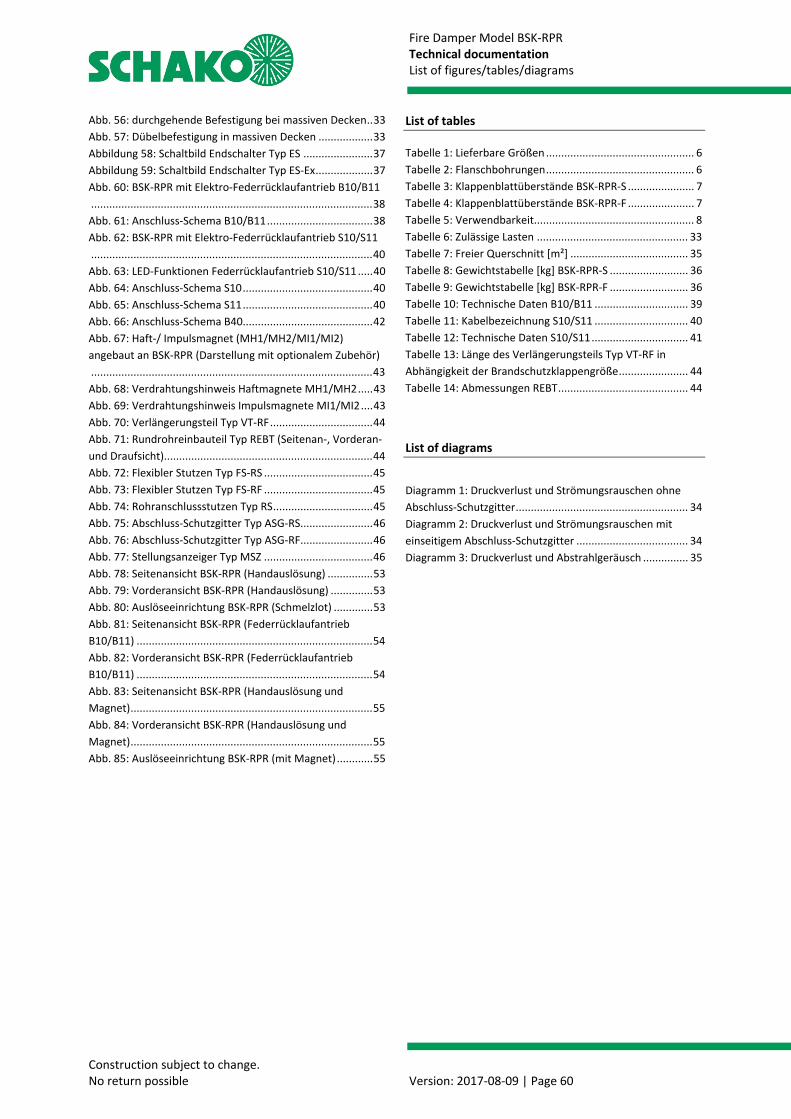
Fire Damper Model BSK-RPR Technical documentation List of figures/tables/diagrams
Construction subject to change. No return possible Version: 2017-08-09 | Page 60
Abb. 56: durchgehende Befestigung bei massiven Decken .. 33 Abb. 57: Dübelbefestigung in massiven Decken .................. 33 Abbildung 58: Schaltbild Endschalter Typ ES ....................... 37 Abbildung 59: Schaltbild Endschalter Typ ES-Ex ................... 37 Abb. 60: BSK-RPR mit Elektro-Federrücklaufantrieb B10/B11 ............................................................................................. 38 Abb. 61: Anschluss-Schema B10/B11 ................................... 38 Abb. 62: BSK-RPR mit Elektro-Federrücklaufantrieb S10/S11 ............................................................................................. 40 Abb. 63: LED-Funktionen Federrücklaufantrieb S10/S11 ..... 40 Abb. 64: Anschluss-Schema S10 ........................................... 40 Abb. 65: Anschluss-Schema S11 ........................................... 40 Abb. 66: Anschluss-Schema B40........................................... 42 Abb. 67: Haft-/ Impulsmagnet (MH1/MH2/MI1/MI2) angebaut an BSK-RPR (Darstellung mit optionalem Zubehör) ............................................................................................. 43 Abb. 68: Verdrahtungshinweis Haftmagnete MH1/MH2 ..... 43 Abb. 69: Verdrahtungshinweis Impulsmagnete MI1/MI2 .... 43 Abb. 70: Verlängerungsteil Typ VT-RF .................................. 44 Abb. 71: Rundrohreinbauteil Typ REBT (Seitenan-, Vorderan- und Draufsicht)..................................................................... 44 Abb. 72: Flexibler Stutzen Typ FS-RS .................................... 45 Abb. 73: Flexibler Stutzen Typ FS-RF .................................... 45 Abb. 74: Rohranschlussstutzen Typ RS ................................. 45 Abb. 75: Abschluss-Schutzgitter Typ ASG-RS ........................ 46 Abb. 76: Abschluss-Schutzgitter Typ ASG-RF ........................ 46 Abb. 77: Stellungsanzeiger Typ MSZ .................................... 46 Abb. 78: Seitenansicht BSK-RPR (Handauslösung) ............... 53 Abb. 79: Vorderansicht BSK-RPR (Handauslösung) .............. 53 Abb. 80: Auslöseeinrichtung BSK-RPR (Schmelzlot) ............. 53 Abb. 81: Seitenansicht BSK-RPR (Federrücklaufantrieb B10/B11) .............................................................................. 54 Abb. 82: Vorderansicht BSK-RPR (Federrücklaufantrieb B10/B11) .............................................................................. 54 Abb. 83: Seitenansicht BSK-RPR (Handauslösung und Magnet) ................................................................................ 55 Abb. 84: Vorderansicht BSK-RPR (Handauslösung und Magnet) ................................................................................ 55 Abb. 85: Auslöseeinrichtung BSK-RPR (mit Magnet) ............ 55
List of tables Tabelle 1: Lieferbare Größen ................................................. 6 Tabelle 2: Flanschbohrungen ................................................. 6 Tabelle 3: Klappenblattüberstände BSK-RPR-S ...................... 7 Tabelle 4: Klappenblattüberstände BSK-RPR-F ...................... 7 Tabelle 5: Verwendbarkeit..................................................... 8 Tabelle 6: Zulässige Lasten .................................................. 33 Tabelle 7: Freier Querschnitt [m²] ....................................... 35 Tabelle 8: Gewichtstabelle [kg] BSK-RPR-S .......................... 36 Tabelle 9: Gewichtstabelle [kg] BSK-RPR-F .......................... 36 Tabelle 10: Technische Daten B10/B11 ............................... 39 Tabelle 11: Kabelbezeichnung S10/S11 ............................... 40 Tabelle 12: Technische Daten S10/S11 ................................ 41 Tabelle 13: Länge des Verlängerungsteils Typ VT-RF in Abhängigkeit der Brandschutzklappengröße ....................... 44 Tabelle 14: Abmessungen REBT ........................................... 44
List of diagrams
Diagramm 1: Druckverlust und Strömungsrauschen ohne Abschluss-Schutzgitter ......................................................... 34 Diagramm 2: Druckverlust und Strömungsrauschen mit einseitigem Abschluss-Schutzgitter ..................................... 34 Diagramm 3: Druckverlust und Abstrahlgeräusch ............... 35