Embed Size (px)
Citation preview
Calibration of Orifice Flow Meter and Venturi Flow Meter
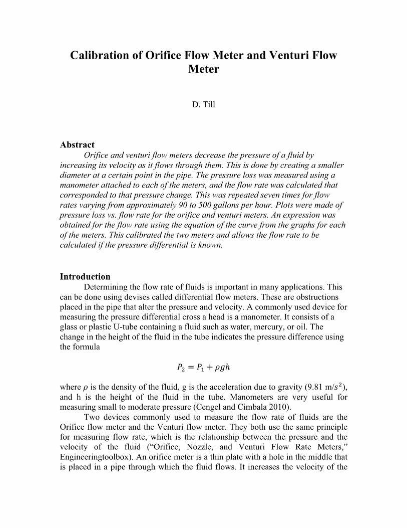
D. Till Abstract Orifice and venturi flow meters decrease the pressure of a fluid by increasing its velocity as it flows through them. This is done by creating a smaller diameter at a certain point in the pipe. The pressure loss was measured using a manometer attached to each of the meters, and the flow rate was calculated that corresponded to that pressure change. This was repeated seven times for flow rates varying from approximately 90 to 500 gallons per hour. Plots were made of pressure loss vs. flow rate for the orifice and venturi meters. An expression was obtained for the flow rate using the equation of the curve from the graphs for each of the meters. This calibrated the two meters and allows the flow rate to be calculated if the pressure differential is known. Introduction Determining the flow rate of fluids is important in many applications. This can be done using devises called differential flow meters. These are obstructions placed in the pipe that alter the pressure and velocity. A commonly used device for measuring the pressure differential cross a head is a manometer. It consists of a glass or plastic U-tube containing a fluid such as water, mercury, or oil. The change in the height of the fluid in the tube indicates the pressure difference using the formula
𝑃! = 𝑃! + 𝜌𝑔ℎ where 𝜌 is the density of the fluid, g is the acceleration due to gravity (9.81 m/𝑠!), and h is the height of the fluid in the tube. Manometers are very useful for measuring small to moderate pressure (Cengel and Cimbala 2010). Two devices commonly used to measure the flow rate of fluids are the Orifice flow meter and the Venturi flow meter. They both use the same principle for measuring flow rate, which is the relationship between the pressure and the velocity of the fluid (“Orifice, Nozzle, and Venturi Flow Rate Meters,” Engineeringtoolbox). An orifice meter is a thin plate with a hole in the middle that is placed in a pipe through which the fluid flows. It increases the velocity of the
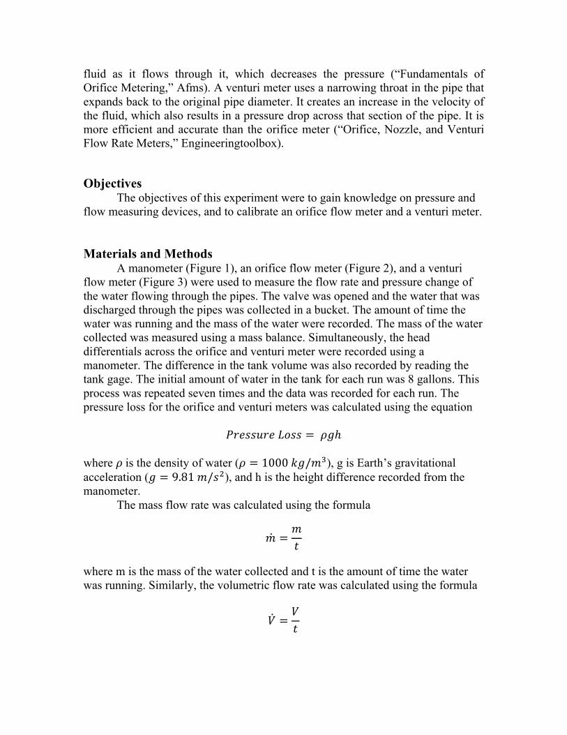
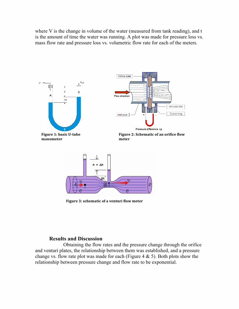
fluid as it flows through it, which decreases the pressure (“Fundamentals of Orifice Metering,” Afms). A venturi meter uses a narrowing throat in the pipe that expands back to the original pipe diameter. It creates an increase in the velocity of the fluid, which also results in a pressure drop across that section of the pipe. It is more efficient and accurate than the orifice meter (“Orifice, Nozzle, and Venturi Flow Rate Meters,” Engineeringtoolbox). Objectives The objectives of this experiment were to gain knowledge on pressure and flow measuring devices, and to calibrate an orifice flow meter and a venturi meter. Materials and Methods A manometer (Figure 1), an orifice flow meter (Figure 2), and a venturi flow meter (Figure 3) were used to measure the flow rate and pressure change of the water flowing through the pipes. The valve was opened and the water that was discharged through the pipes was collected in a bucket. The amount of time the water was running and the mass of the water were recorded. The mass of the water collected was measured using a mass balance. Simultaneously, the head differentials across the orifice and venturi meter were recorded using a manometer. The difference in the tank volume was also recorded by reading the tank gage. The initial amount of water in the tank for each run was 8 gallons. This process was repeated seven times and the data was recorded for each run. The pressure loss for the orifice and venturi meters was calculated using the equation
𝑃𝑟𝑒𝑠𝑠𝑢𝑟𝑒 𝐿𝑜𝑠𝑠 = 𝜌𝑔ℎ where 𝜌 is the density of water (𝜌 = 1000 𝑘𝑔/𝑚!), g is Earth’s gravitational acceleration (𝑔 = 9.81 𝑚/𝑠!), and h is the height difference recorded from the manometer. The mass flow rate was calculated using the formula
𝑚 =𝑚𝑡
where m is the mass of the water collected and t is the amount of time the water was running. Similarly, the volumetric flow rate was calculated using the formula
𝑉 =𝑉𝑡
where V is the change in volume of the water (measured from tank reading), and t is the amount of time the water was running. A plot was made for pressure loss vs. mass flow rate and pressure loss vs. volumetric flow rate for each of the meters.
Results and Discussion Obtaining the flow rates and the pressure change through the orifice
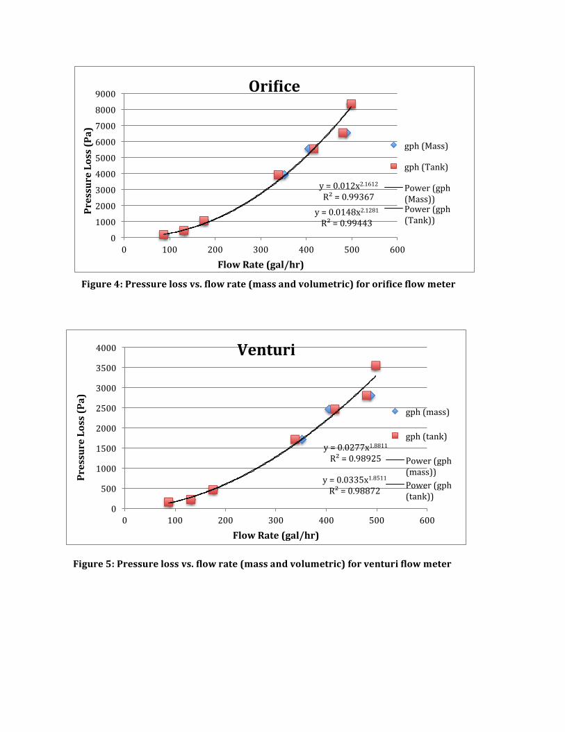
and venturi plates, the relationship between them was established, and a pressure change vs. flow rate plot was made for each (Figure 4 & 5). Both plots show the relationship between pressure change and flow rate to be exponential.
Figure 2: Schematic of an orifice flow meter
Figure 1: basic U-‐tube manometer
Figure 3: schematic of a venturi flow meter
y = 0.012x2.1612 R² = 0.99367
y = 0.0148x2.1281 R² = 0.99443
0
1000
2000
3000
4000
5000
6000
7000
8000
9000
0 100 200 300 400 500 600
Pressure Loss (Pa)
Flow Rate (gal/hr)
OriCice
gph (Mass)
gph (Tank)
Power (gph (Mass)) Power (gph (Tank))
y = 0.0277x1.8811 R² = 0.98925
y = 0.0335x1.8511 R² = 0.98872
0
500
1000
1500
2000
2500
3000
3500
4000
0 100 200 300 400 500 600
Pressure Loss (Pa)
Flow Rate (gal/hr)
Venturi
gph (mass)
gph (tank)
Power (gph (mass)) Power (gph (tank))
Figure 4: Pressure loss vs. flow rate (mass and volumetric) for orifice flow meter
Figure 5: Pressure loss vs. flow rate (mass and volumetric) for venturi flow meter
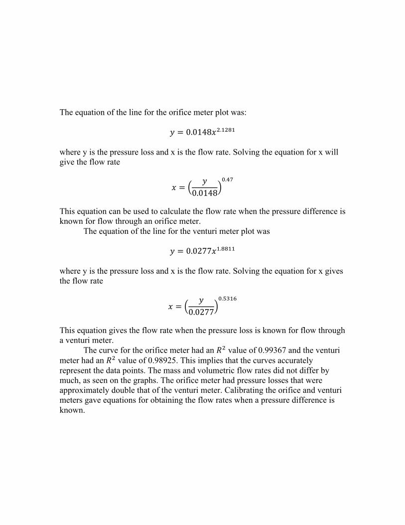
The equation of the line for the orifice meter plot was:
𝑦 = 0.0148𝑥!.!"#! where y is the pressure loss and x is the flow rate. Solving the equation for x will give the flow rate
𝑥 =𝑦
0.0148
!.!"
This equation can be used to calculate the flow rate when the pressure difference is known for flow through an orifice meter. The equation of the line for the venturi meter plot was
𝑦 = 0.0277𝑥!.!!"" where y is the pressure loss and x is the flow rate. Solving the equation for x gives the flow rate
𝑥 =𝑦
0.0277
!.!"#$
This equation gives the flow rate when the pressure loss is known for flow through a venturi meter. The curve for the orifice meter had an 𝑅! value of 0.99367 and the venturi meter had an 𝑅! value of 0.98925. This implies that the curves accurately represent the data points. The mass and volumetric flow rates did not differ by much, as seen on the graphs. The orifice meter had pressure losses that were approximately double that of the venturi meter. Calibrating the orifice and venturi meters gave equations for obtaining the flow rates when a pressure difference is known.
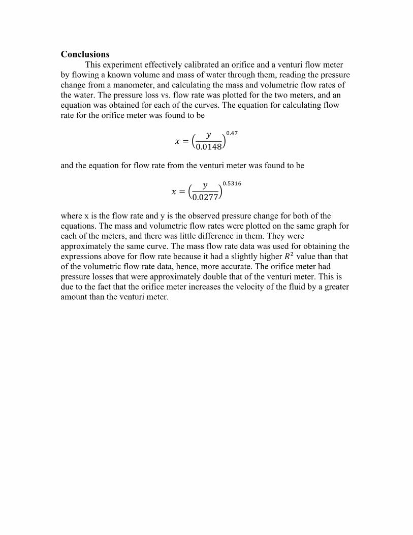
Conclusions This experiment effectively calibrated an orifice and a venturi flow meter by flowing a known volume and mass of water through them, reading the pressure change from a manometer, and calculating the mass and volumetric flow rates of the water. The pressure loss vs. flow rate was plotted for the two meters, and an equation was obtained for each of the curves. The equation for calculating flow rate for the orifice meter was found to be
𝑥 =𝑦
0.0148
!.!"
and the equation for flow rate from the venturi meter was found to be
𝑥 =𝑦
0.0277
!.!"#$
where x is the flow rate and y is the observed pressure change for both of the equations. The mass and volumetric flow rates were plotted on the same graph for each of the meters, and there was little difference in them. They were approximately the same curve. The mass flow rate data was used for obtaining the expressions above for flow rate because it had a slightly higher 𝑅! value than that of the volumetric flow rate data, hence, more accurate. The orifice meter had pressure losses that were approximately double that of the venturi meter. This is due to the fact that the orifice meter increases the velocity of the fluid by a greater amount than the venturi meter.
References
Çengel, A., and J. M. Cimbala. Fluid Mechanics: Fundamentals and Applications. 2nd ed.
Boston: McGraw-Hill Higher Education, 2010. Print.
"Fundamentals of Orifice Metering." Afms.org. Smith Metering, Inc, n.d. Web. 30 Sept. 2013.
<http://www.afms.org/Docs/gas/Fundamenatls_of_Orifice.pdf>.
"Orifice, Nozzle and Venturi Flow Rate Meters." Engineeringtoolbox.com. N.p., n.d. Web. 30
Sept. 2013. <http://www.engineeringtoolbox.com/orifice-nozzle-venturi-d_590.html>.