Embed Size (px)
Citation preview

7/27/2019 BSC6900V900R011 GO Hardware Structure and System Description
http://slidepdf.com/reader/full/bsc6900v900r011-go-hardware-structure-and-system-description 1/54
Security Level: Internal Use
www.huawei.com
2009/06
BSC6900V9R011 GO
Hardware Structure
and SystemDescription
TSD Wireless Product Service Department-GBSS
ISSUE1.0

7/27/2019 BSC6900V900R011 GO Hardware Structure and System Description
http://slidepdf.com/reader/full/bsc6900v900r011-go-hardware-structure-and-system-description 2/54
HUAWEI TECHNOLOGIES CO., LTD. All rights reserved Page 2
The BSC6900 is an important network
element of Huawei Single RAN solution. It
adopts the industry-leading multiple radio
access technologies, IP transmissionmode, and modular design. The BSC6900
can be flexibly configured as a BSC6900
GSM, BSC6900 UMTS, or BSC6900 GU
as required in different networks.
7/27/2019 BSC6900V900R011 GO Hardware Structure and System Description
http://slidepdf.com/reader/full/bsc6900v900r011-go-hardware-structure-and-system-description 3/54
HUAWEI TECHNOLOGIES CO., LTD. All rights reserved Page 3
Know the functions and features of BSC6900
Master the hardware structure of BSC6900
Master the signal flow
Master the typical configuration of BSC6900
7/27/2019 BSC6900V900R011 GO Hardware Structure and System Description
http://slidepdf.com/reader/full/bsc6900v900r011-go-hardware-structure-and-system-description 4/54
HUAWEI TECHNOLOGIES CO., LTD. All rights reserved Page 4
Reference
BSC6900 Technical Description
BSC6900 Hardware Description
7/27/2019 BSC6900V900R011 GO Hardware Structure and System Description
http://slidepdf.com/reader/full/bsc6900v900r011-go-hardware-structure-and-system-description 5/54
HUAWEI TECHNOLOGIES CO., LTD. All rights reserved Page 5
Chapter 1 BSC6900 System Description
Chapter 2 BSC6900 Hardware Structure
Chapter 3 BSC6900 Signal Flow
Chapter 4 BSC6900 Typical Configuration
7/27/2019 BSC6900V900R011 GO Hardware Structure and System Description
http://slidepdf.com/reader/full/bsc6900v900r011-go-hardware-structure-and-system-description 6/54
HUAWEI TECHNOLOGIES CO., LTD. All rights reserved Page 6
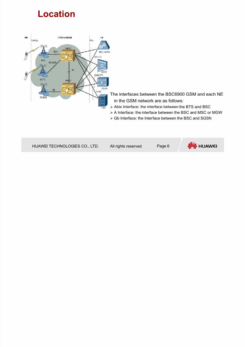
Location
The interfaces between the BSC6900 GSM and each NE
in the GSM network are as follows:
Abis Interface: the interface between the BTS and BSC A Interface: the interface between the BSC and MSC or MGW
Gb Interface: the Interface between the BSC and SGSN

7/27/2019 BSC6900V900R011 GO Hardware Structure and System Description
http://slidepdf.com/reader/full/bsc6900v900r011-go-hardware-structure-and-system-description 7/54HUAWEI TECHNOLOGIES CO., LTD. All rights reserved Page 7
• Smooth evolution from BSC to RNC with software upgrade
• Reducing CAPEX by reusing hardware
• Dynamic capacity adjustment between 2G&3G
Software
upgrade
BSC6900 Product Characters-multi-
mode amalgamation
BSC
BSC
RNC
RNC
RNC
BSC
GSM&UMTS cabinet GSM&UMTS co-cabinet
RNC
RNC
BSC

7/27/2019 BSC6900V900R011 GO Hardware Structure and System Description
http://slidepdf.com/reader/full/bsc6900v900r011-go-hardware-structure-and-system-description 8/54
HUAWEI TECHNOLOGIES CO., LTD. All rights reserved Page 8
BSC6900 Capacity Index
BSC6900 GSM only
Item 1MPS+1TCS 1MPS+1EPS+2TCS 1MPS+2EPS+2TCS
Number of cabinets
2 2 2
BHCA 1750 3500 5250
Traffic volume
(Erl)
6500 13000 19500
Number of TRXs 1024 2048 3072
Number of active
PDCHs(MCS-9)
4096 8192 12288
Typical configuration specifications of the BSC6900 GSM(BM/TC
separated and Abis over non-IP R11 board)
7/27/2019 BSC6900V900R011 GO Hardware Structure and System Description
http://slidepdf.com/reader/full/bsc6900v900r011-go-hardware-structure-and-system-description 9/54
HUAWEI TECHNOLOGIES CO., LTD. All rights reserved Page 9
Chapter 1 BSC6900 System Description
Chapter 2 BSC6900 Hardware Structure
Chapter 3 BSC6900 Signal Flow
Chapter 4 BSC6900 Typical Configuration
7/27/2019 BSC6900V900R011 GO Hardware Structure and System Description
http://slidepdf.com/reader/full/bsc6900v900r011-go-hardware-structure-and-system-description 10/54
HUAWEI TECHNOLOGIES CO., LTD. All rights reserved Page 10
Chapter 2 BSC6900 Hardware Structure
2.1 Frame and Subrack
2.2 Board Introduction
2.3 Cable Introduction
7/27/2019 BSC6900V900R011 GO Hardware Structure and System Description
http://slidepdf.com/reader/full/bsc6900v900r011-go-hardware-structure-and-system-description 11/54
HUAWEI TECHNOLOGIES CO., LTD. All rights reserved Page 11
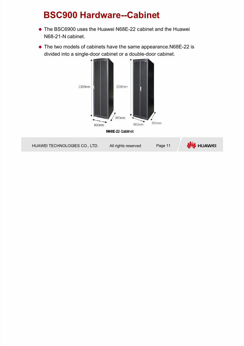
BSC900 Hardware--Cabinet
The BSC6900 uses the Huawei N68E-22 cabinet and the Huawei
N68-21-N cabinet.
The two models of cabinets have the same appearance.N68E-22 is
divided into a single-door cabinet or a double-door cabinet.

7/27/2019 BSC6900V900R011 GO Hardware Structure and System Description
http://slidepdf.com/reader/full/bsc6900v900r011-go-hardware-structure-and-system-description 12/54
HUAWEI TECHNOLOGIES CO., LTD. All rights reserved Page 12
BSC900 Hardware--Cabinet
The BSC6900 GSM cabinet is classified into
main processing rack (MPS), extended
processing rack (EPS), and transcoder rack
(TC).
7/27/2019 BSC6900V900R011 GO Hardware Structure and System Description
http://slidepdf.com/reader/full/bsc6900v900r011-go-hardware-structure-and-system-description 13/54
HUAWEI TECHNOLOGIES CO., LTD. All rights reserved Page 13
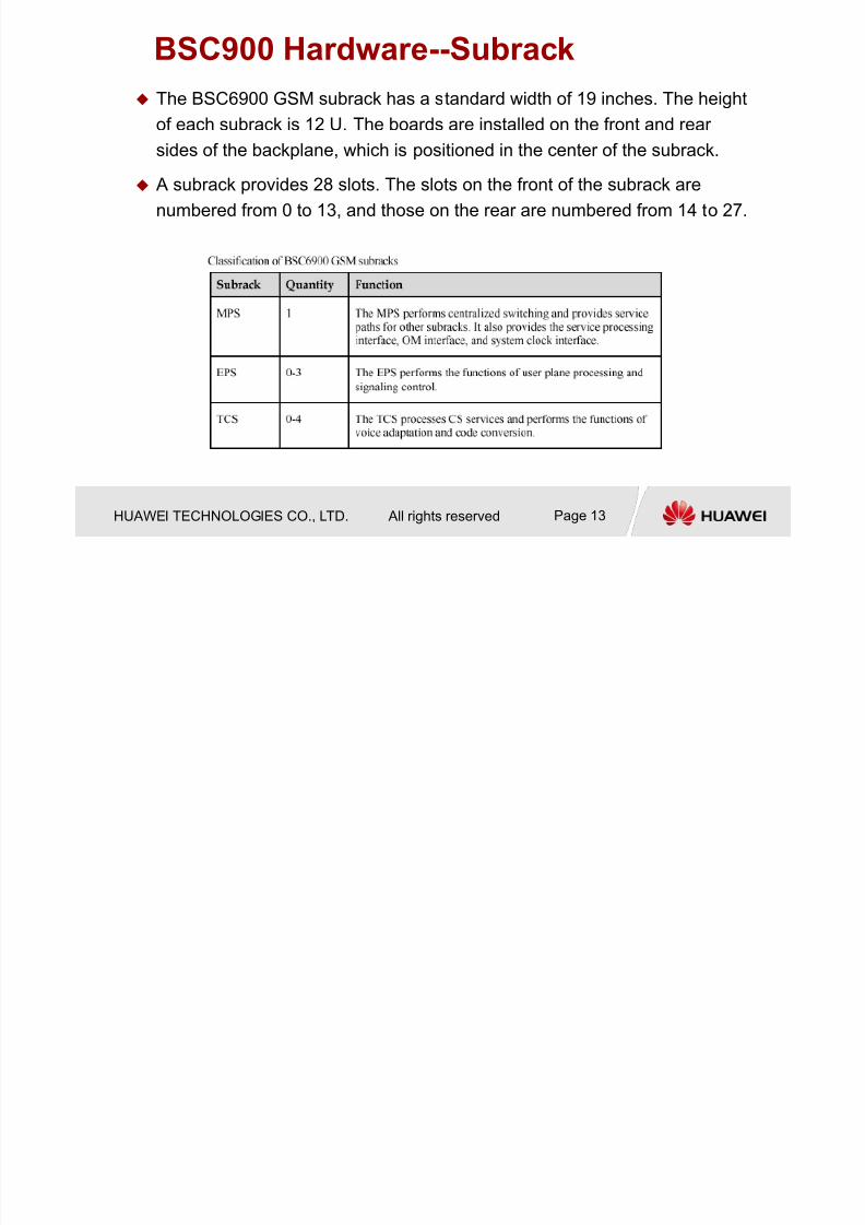
BSC900 Hardware--Subrack
The BSC6900 GSM subrack has a standard width of 19 inches. The height
of each subrack is 12 U. The boards are installed on the front and rear sides of the backplane, which is positioned in the center of the subrack.
A subrack provides 28 slots. The slots on the front of the subrack are
numbered from 0 to 13, and those on the rear are numbered from 14 to 27.
7/27/2019 BSC6900V900R011 GO Hardware Structure and System Description
http://slidepdf.com/reader/full/bsc6900v900r011-go-hardware-structure-and-system-description 14/54
HUAWEI TECHNOLOGIES CO., LTD. All rights reserved Page 14
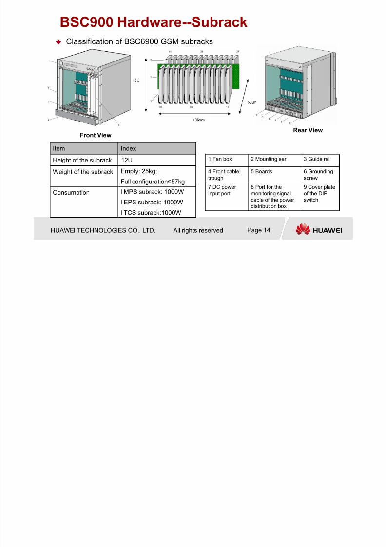
BSC900 Hardware--Subrack
1 Fan box 2 Mounting ear 3 Guide rail
4 Front cable
trough
5 Boards 6 Grounding
screw
7 DC power
input port
8 Port for the
monitoring signal
cable of the power
distribution box
9 Cover plate
of the DIP
switch
Front ViewRear View
Classification of BSC6900 GSM subracks
Item Index
Height of the subrack 12U
Weight of the subrack Empty: 25kg;
Full configuration≤57kg
Consumption l MPS subrack: 1000W
l EPS subrack: 1000W
l TCS subrack:1000W

7/27/2019 BSC6900V900R011 GO Hardware Structure and System Description
http://slidepdf.com/reader/full/bsc6900v900r011-go-hardware-structure-and-system-description 15/54
HUAWEI TECHNOLOGIES CO., LTD. All rights reserved Page 15
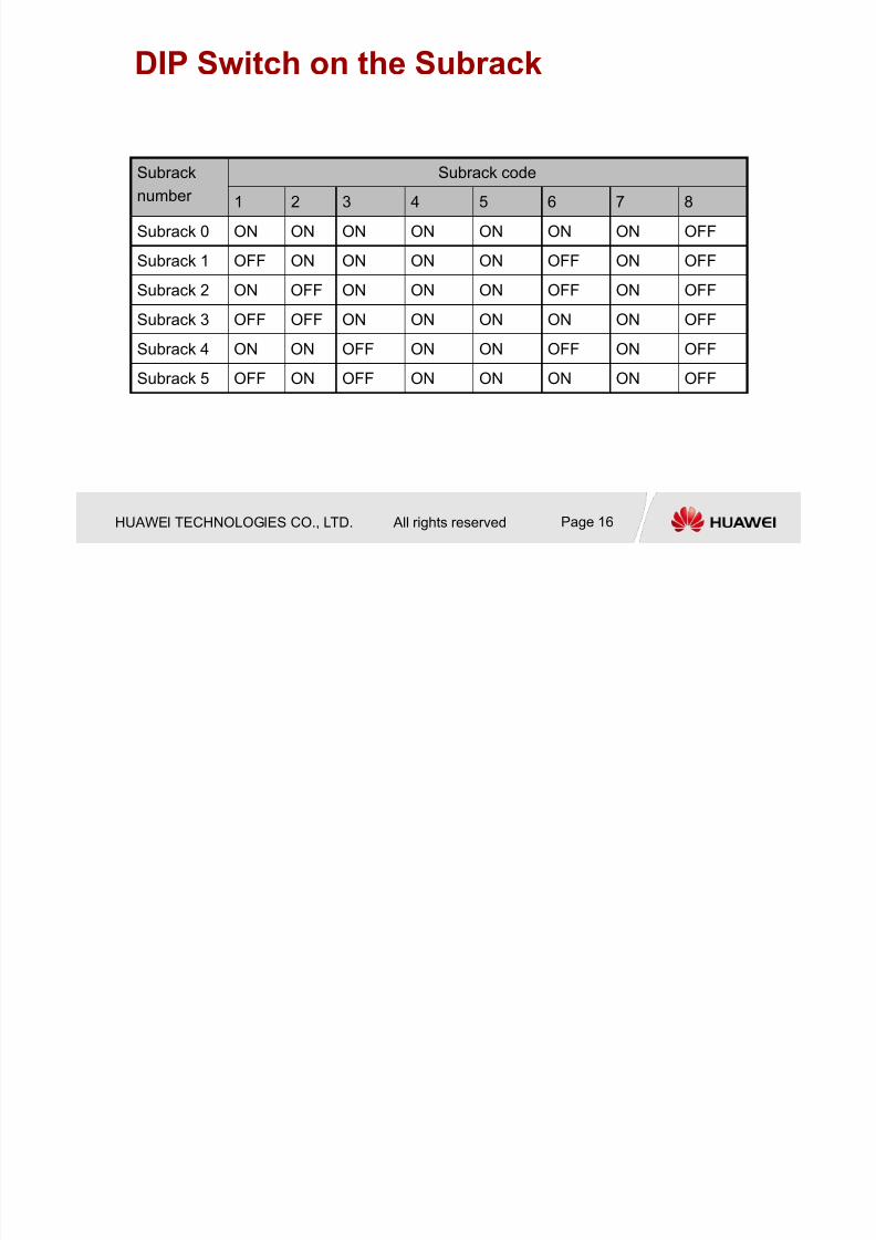
DIP Switch on the Subrack The DIP switch on the subrack has eight bits numbered in ascending
order from 1 to 8
If the bit is set to ON, it indicates 0. If the bit is set to OFF, it indicates 1.
7/27/2019 BSC6900V900R011 GO Hardware Structure and System Description
http://slidepdf.com/reader/full/bsc6900v900r011-go-hardware-structure-and-system-description 16/54
HUAWEI TECHNOLOGIES CO., LTD. All rights reserved Page 16
DIP Switch on the Subrack
Subrack
number
Subrack code
1 2 3 4 5 6 7 8
Subrack 0 ON ON ON ON ON ON ON OFF
Subrack 1 OFF ON ON ON ON OFF ON OFF
Subrack 2 ON OFF ON ON ON OFF ON OFF
Subrack 3 OFF OFF ON ON ON ON ON OFF
Subrack 4 ON ON OFF ON ON OFF ON OFF
Subrack 5 OFF ON OFF ON ON ON ON OFF

7/27/2019 BSC6900V900R011 GO Hardware Structure and System Description
http://slidepdf.com/reader/full/bsc6900v900r011-go-hardware-structure-and-system-description 17/54
HUAWEI TECHNOLOGIES CO., LTD. All rights reserved Page 17
Chapter 2 BSC6900 Hardware Structure
2.1 Frame and Subrack
2.2 Board Introduction
2.3 Cable Introduction

7/27/2019 BSC6900V900R011 GO Hardware Structure and System Description
http://slidepdf.com/reader/full/bsc6900v900r011-go-hardware-structure-and-system-description 18/54
HUAWEI TECHNOLOGIES CO., LTD. All rights reserved Page 18
BSC6900 Overall Structure The overall structure of the BSC6900
Switching Subsystem;
Service Processing Subsystem;
Clock Synchronization Subsystem;
Interface Synchronization Subsystem;
OM Subsystem.
GO-Mode
7/27/2019 BSC6900V900R011 GO Hardware Structure and System Description
http://slidepdf.com/reader/full/bsc6900v900r011-go-hardware-structure-and-system-description 19/54
HUAWEI TECHNOLOGIES CO., LTD. All rights reserved Page 19
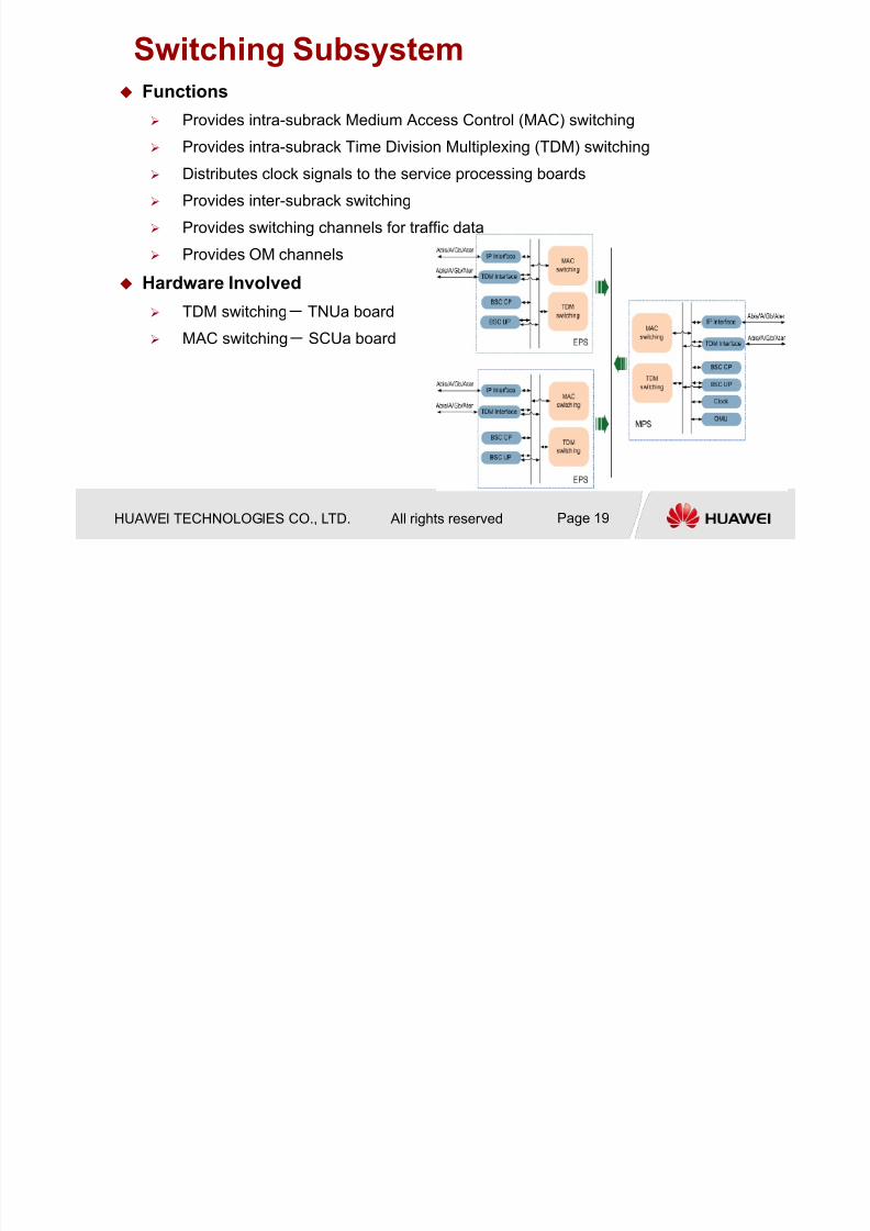
Switching Subsystem Functions
Provides intra-subrack Medium Access Control (MAC) switching
Provides intra-subrack Time Division Multiplexing (TDM) switching
Distributes clock signals to the service processing boards
Provides inter-subrack switching
Provides switching channels for traffic data
Provides OM channels
Hardware Involved
TDM switching- TNUa board
MAC switching- SCUa board
7/27/2019 BSC6900V900R011 GO Hardware Structure and System Description
http://slidepdf.com/reader/full/bsc6900v900r011-go-hardware-structure-and-system-description 20/54
HUAWEI TECHNOLOGIES CO., LTD. All rights reserved Page 20
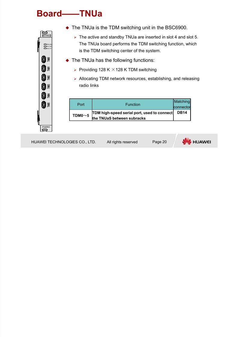
Board——TNUa
Port FunctionMatching
connector
TDM0~5TDM high-speed serial port, used to connect
the TNUaS between subracks
DB14
GTNU
PARC
RUN
ALM
ACT
T N M
5
T N M 4
T N M 0
T N
M 1
T N M 2
T N M 3
The TNUa is the TDM switching unit in the BSC6900.
The active and standby TNUa are inserted in slot 4 and slot 5.
The TNUa board performs the TDM switching function, which
is the TDM switching center of the system.
The TNUa has the following functions:
Providing 128 K×128 K TDM switching
Allocating TDM network resources, establishing, and releasing
radio links
7/27/2019 BSC6900V900R011 GO Hardware Structure and System Description
http://slidepdf.com/reader/full/bsc6900v900r011-go-hardware-structure-and-system-description 21/54
HUAWEI TECHNOLOGIES CO., LTD. All rights reserved Page 21
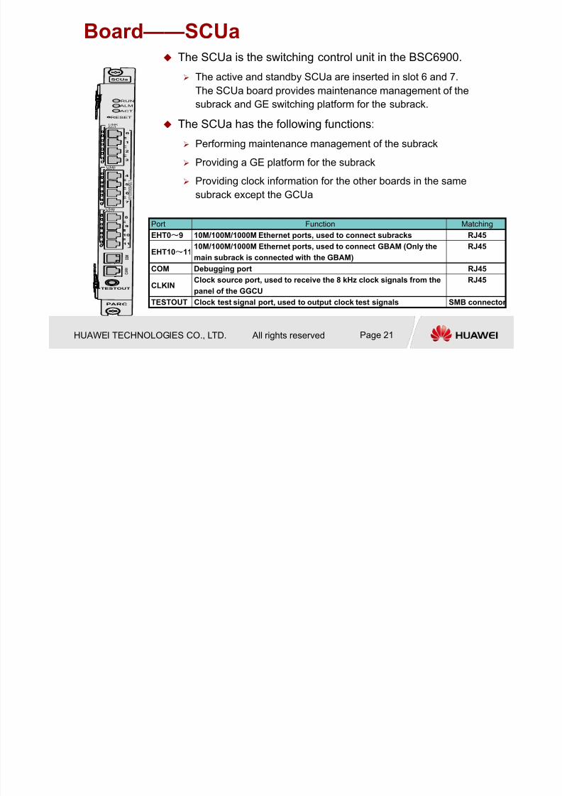
Board——SCUa
Port Function Matching
EHT0~9 10M/100M/1000M Ethernet ports, used to connect subracks RJ45
EHT10~11 10M/100M/1000M Ethernet ports, used to connect GBAM (Only themain subrack is connected with the GBAM)
RJ45
COM Debugging port RJ45
CLKINClock source port, used to receive the 8 kHz clock signals from the
panel of the GGCU
RJ45
TESTOUT Clock test signal port, used to output clock test signals SMB connector
The SCUa is the switching control unit in the BSC6900.
The active and standby SCUa are inserted in slot 6 and 7.
The SCUa board provides maintenance management of the
subrack and GE switching platform for the subrack.
The SCUa has the following functions:
Performing maintenance management of the subrack
Providing a GE platform for the subrack Providing clock information for the other boards in the same
subrack except the GCUa
SCUa
PARC
RUN
ALM
ACT
C O M
TESTOUT
C L
K I N
ACT
LINK
1 0
/ 1 0 0
/ 1 0 0 0 B A
S E
- T
RESET
ACTLINK
8
9
0
1
2
3
4
5
6
7
11
10
ACTLINK

7/27/2019 BSC6900V900R011 GO Hardware Structure and System Description
http://slidepdf.com/reader/full/bsc6900v900r011-go-hardware-structure-and-system-description 22/54
HUAWEI TECHNOLOGIES CO., LTD. All rights reserved Page 22
Service Processing Subsystem Functions
User data transfer
Radio channel ciphering and deciphering
System admission control
Data integrity protection
Mobility management
Cell broadcast service control
Data volume reporting
Radio access management
CS service processing
PS service processing
Radio resource management and control
System information and user message tracing

7/27/2019 BSC6900V900R011 GO Hardware Structure and System Description
http://slidepdf.com/reader/full/bsc6900v900r011-go-hardware-structure-and-system-description 23/54
HUAWEI TECHNOLOGIES CO., LTD. All rights reserved Page 23
Service Processing Subsystem
Hardware Involved
XPUa/b board, SPUa/b board, DPU/c/d board
Board Specification
XPU/SPU is the signaling processing unit
SPU board can process GSM/UMTS signaling panel, XPU board can process
GSM signaling panel
SPU board Works for BSC6900 GU mode
XPU board Works for BSC6900 GSM only mode
Services Process Unit DPUc/d/
7/27/2019 BSC6900V900R011 GO Hardware Structure and System Description
http://slidepdf.com/reader/full/bsc6900v900r011-go-hardware-structure-and-system-description 24/54
HUAWEI TECHNOLOGIES CO., LTD. All rights reserved Page 24
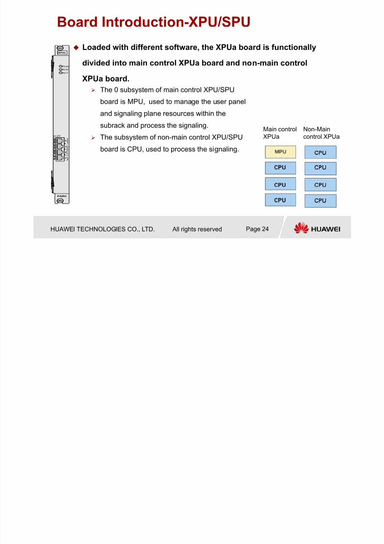
Board Introduction-XPU/SPU
Loaded with different software, the XPUa board is functionally
divided into main control XPUa board and non-main control
XPUa board.
XPUa
PARC
RUN
ALM
ACT
1 0 / 1 0 0 / 1 0 0 0 B A S E -
T
ACTLINK
0
1
2
3
The 0 subsystem of main control XPU/SPU
board is MPU, used to manage the user panel
and signaling plane resources within the
subrack and process the signaling.
The subsystem of non-main control XPU/SPU
board is CPU, used to process the signaling.
Main control
XPUa
Non-Main
control XPUa
7/27/2019 BSC6900V900R011 GO Hardware Structure and System Description
http://slidepdf.com/reader/full/bsc6900v900r011-go-hardware-structure-and-system-description 25/54
HUAWEI TECHNOLOGIES CO., LTD. All rights reserved Page 25
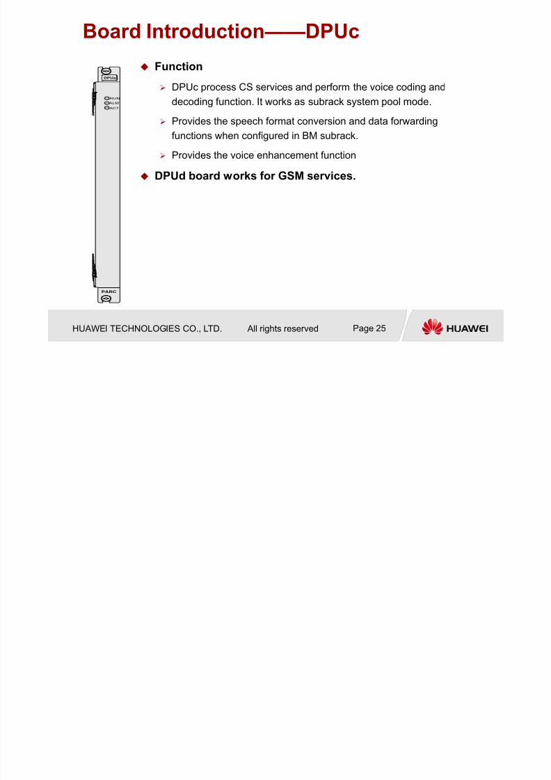
Board Introduction——DPUc
Function
DPUc process CS services and perform the voice coding and
decoding function. It works as subrack system pool mode.
Provides the speech format conversion and data forwarding
functions when configured in BM subrack.
Provides the voice enhancement function
DPUd board works for GSM services.
DPUa
PARC
RUN
ALM
ACT
7/27/2019 BSC6900V900R011 GO Hardware Structure and System Description
http://slidepdf.com/reader/full/bsc6900v900r011-go-hardware-structure-and-system-description 26/54
HUAWEI TECHNOLOGIES CO., LTD. All rights reserved Page 26
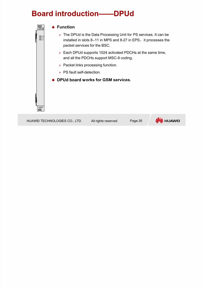
Board introduction——DPUd
Function
The DPUd is the Data Processing Unit for PS services. It can be
installed in slots 8 –11 in MPS and 8-27 in EPS,it processes the
packet services for the BSC.
Each DPUd supports 1024 activated PDCHs at the same time,
and all the PDCHs support MSC-9 coding. Packet links processing function.
PS fault self-detection.
DPUd board works for GSM services.
DPUa
PARC
RUN
ALM
ACT

7/27/2019 BSC6900V900R011 GO Hardware Structure and System Description
http://slidepdf.com/reader/full/bsc6900v900r011-go-hardware-structure-and-system-description 27/54
HUAWEI TECHNOLOGIES CO., LTD. All rights reserved Page 27
Subsystems Five: Interface Board System
Board
Type
Physical
Board
Board specification Scene
EIUa Transmits, receives, encodes, and decodes 32 E1s/T1s. GSM Only
OIUa Provides one STM-1 port for TDM transmission GSM Only、GU
Old
Boards
FG2a Provides eight channels over FE ports or two channels over
GE electrical ports
GSM Only、GU
GOUa Provides two channels over GE optical ports GSM Only、GU
PEUa Provides 32 channels of E1s/T1s for HDLC transmission
Extracts line clock signals
GSM Only、GU
Multi-
kernel
Boards
FG2c Provides 12 channels over FE ports or four channels over
GE electrical ports GSM Only、GU
GOUc Provides four channels over GE optical ports GSM Only、GU
POUc Provides four channels over channelized optical STM-1/OC-3 ports based on IP protocol
GSM Only、GU
7/27/2019 BSC6900V900R011 GO Hardware Structure and System Description
http://slidepdf.com/reader/full/bsc6900v900r011-go-hardware-structure-and-system-description 28/54
HUAWEI TECHNOLOGIES CO., LTD. All rights reserved Page 28
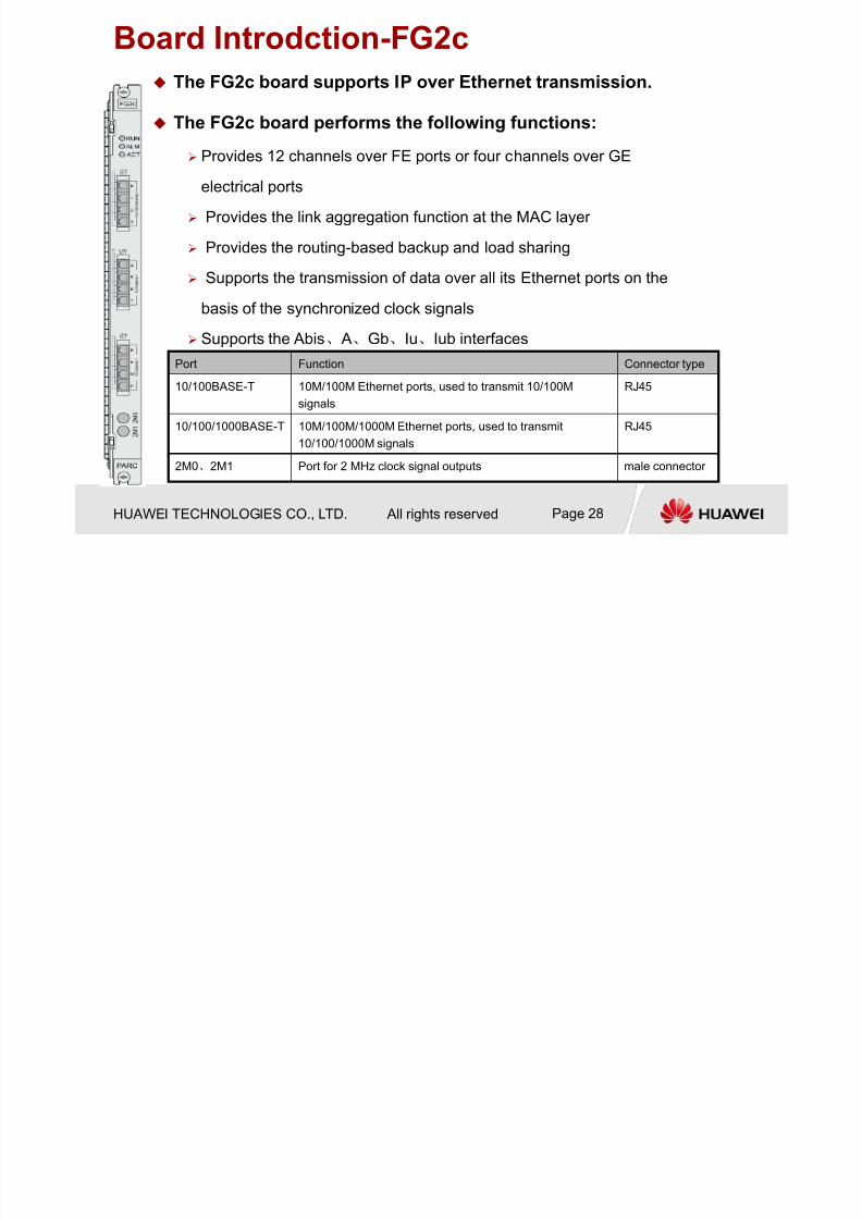
Board Introdction-FG2c
The FG2c board supports IP over Ethernet transmission.
The FG2c board performs the following functions: Provides 12 channels over FE ports or four channels over GE
electrical ports
Provides the link aggregation function at the MAC layer
Provides the routing-based backup and load sharing
Supports the transmission of data over all its Ethernet ports on the
basis of the synchronized clock signals
Supports the Abis、 A、Gb、Iu、Iub interfaces
Port Function Connector type
10/100BASE-T 10M/100M Ethernet ports, used to transmit 10/100M
signals
RJ45
10/100/1000BASE-T 10M/100M/1000M Ethernet ports, used to transmit
10/100/1000M signals
RJ45
2M0、2M1 Port for 2 MHz clock signal outputs male connector
7/27/2019 BSC6900V900R011 GO Hardware Structure and System Description
http://slidepdf.com/reader/full/bsc6900v900r011-go-hardware-structure-and-system-description 29/54
HUAWEI TECHNOLOGIES CO., LTD. All rights reserved Page 29
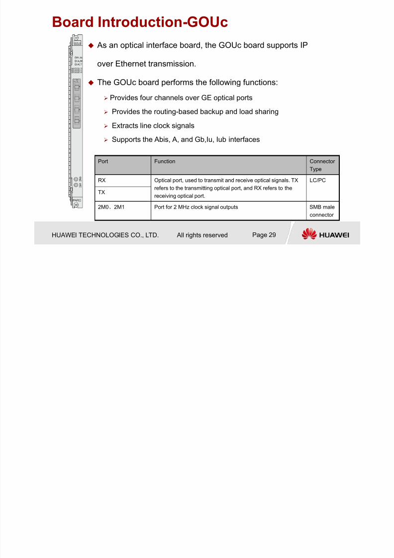
Board Introduction-GOUc
As an optical interface board, the GOUc board supports IP
over Ethernet transmission.
The GOUc board performs the following functions:
Provides four channels over GE optical ports
Provides the routing-based backup and load sharing
Extracts line clock signals
Supports the Abis, A, and Gb,Iu, Iub interfaces
Port Function Connector
Type
RX Optical port, used to transmit and receive optical signals. TX
refers to the transmitting optical port, and RX refers to the
receiving optical port.
LC/PC
TX
2M0、2M1 Port for 2 MHz clock signal outputs SMB male
connector
7/27/2019 BSC6900V900R011 GO Hardware Structure and System Description
http://slidepdf.com/reader/full/bsc6900v900r011-go-hardware-structure-and-system-description 30/54
HUAWEI TECHNOLOGIES CO., LTD. All rights reserved Page 30
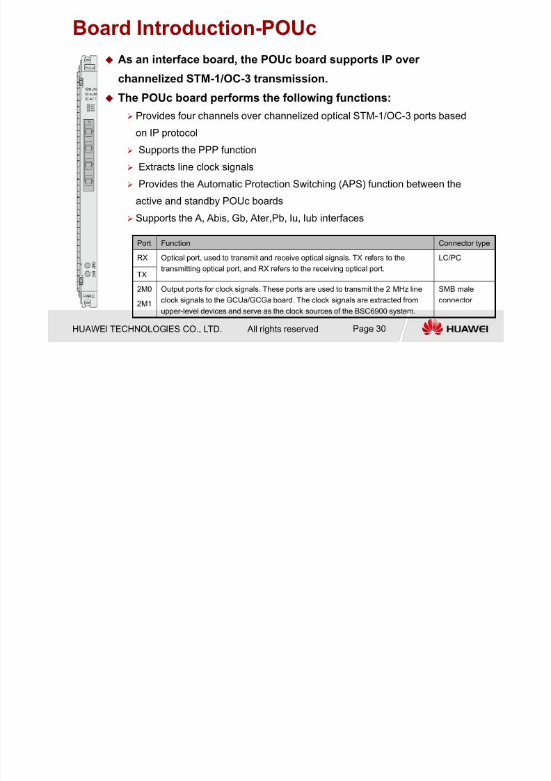
Board Introduction-POUc
As an interface board, the POUc board supports IP over
channelized STM-1/OC-3 transmission. The POUc board performs the following functions:
Provides four channels over channelized optical STM-1/OC-3 ports based
on IP protocol
Supports the PPP function
Extracts line clock signals
Provides the Automatic Protection Switching (APS) function between the
active and standby POUc boards
Supports the A, Abis, Gb, Ater,Pb, Iu, Iub interfaces
Port Function Connector type
RX Optical port, used to transmit and receive optical signals. TX refers to the
transmitting optical port, and RX refers to the receiving optical port.
LC/PC
TX
2M0
2M1
Output ports for clock signals. These ports are used to transmit the 2 MHz line
clock signals to the GCUa/GCGa board. The clock signals are extracted from
upper-level devices and serve as the clock sources of the BSC6900 system.
SMB male
connector

7/27/2019 BSC6900V900R011 GO Hardware Structure and System Description
http://slidepdf.com/reader/full/bsc6900v900r011-go-hardware-structure-and-system-description 31/54
HUAWEI TECHNOLOGIES CO., LTD. All rights reserved Page 31
Subsystems Four: Clock Subsystem Clock Source
Bits clock
Line clock
GPS
Reference Clock for the MPS or EPS
The reference clocks are provided by the GCUa. The reference clocks generate
8kHz clock signals through the GCUa.
MPS: The clock signals are sent to the SCUa in the MPSa subrack through the
backplane. Then, the clock signals are sent to other boards in the same subrack.
EPS: The clock signals are sent to the SCUa board in the EPSa subrack through
the clock cable. Then, the signals are sent to other boards through the backplane.
Reference Clock for the TCS Each TCS extracts line clock from the A interface. The line clock is processed
through A interface panel and then generates 8 KHz clock signals.
The clock signals are sent to the SCUa in the subrack through the backplane. Then
the clock signals are sent to other boards in the same subrack.
7/27/2019 BSC6900V900R011 GO Hardware Structure and System Description
http://slidepdf.com/reader/full/bsc6900v900r011-go-hardware-structure-and-system-description 32/54
HUAWEI TECHNOLOGIES CO., LTD. All rights reserved Page 32
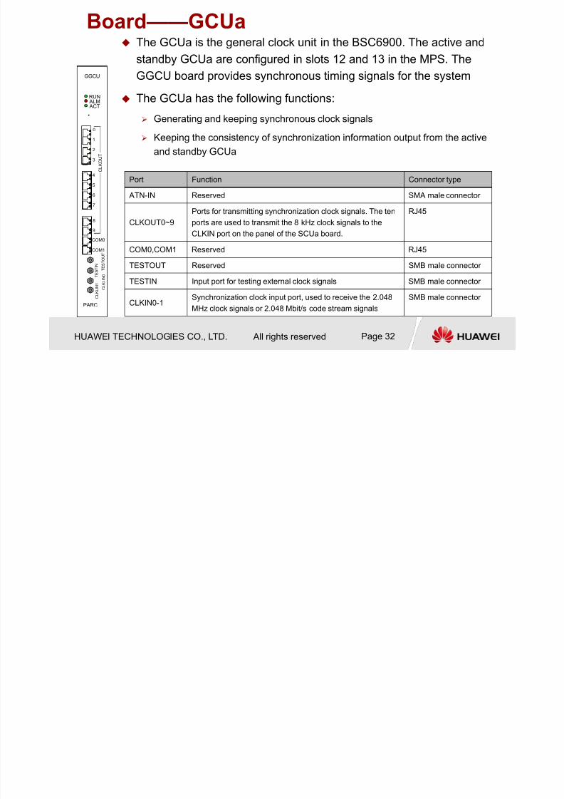
Board——GCUa
GGCU
PARC
RUN ALM ACT
8
9
COM0
COM1
0
1
2
3
4
5
6
7
C L K O U T
T E S T I N
T E S T O U T
C L K L I N 1
C L K L I N 0
The GCUa is the general clock unit in the BSC6900. The active and
standby GCUa are configured in slots 12 and 13 in the MPS. The
GGCU board provides synchronous timing signals for the system
The GCUa has the following functions:
Generating and keeping synchronous clock signals
Keeping the consistency of synchronization information output from the active
and standby GCUa
Port Function Connector type
ATN-IN Reserved SMA male connector
CLKOUT0~9
Ports for transmitting synchronization clock signals. The ten
ports are used to transmit the 8 kHz clock signals to the
CLKIN port on the panel of the SCUa board.
RJ45
COM0,COM1 Reserved RJ45
TESTOUT Reserved SMB male connector
TESTIN Input port for testing external clock signals SMB male connector
CLKIN0-1Synchronization clock input port, used to receive the 2.048
MHz clock signals or 2.048 Mbit/s code stream signals
SMB male connector
7/27/2019 BSC6900V900R011 GO Hardware Structure and System Description
http://slidepdf.com/reader/full/bsc6900v900r011-go-hardware-structure-and-system-description 33/54
HUAWEI TECHNOLOGIES CO., LTD. All rights reserved Page 33
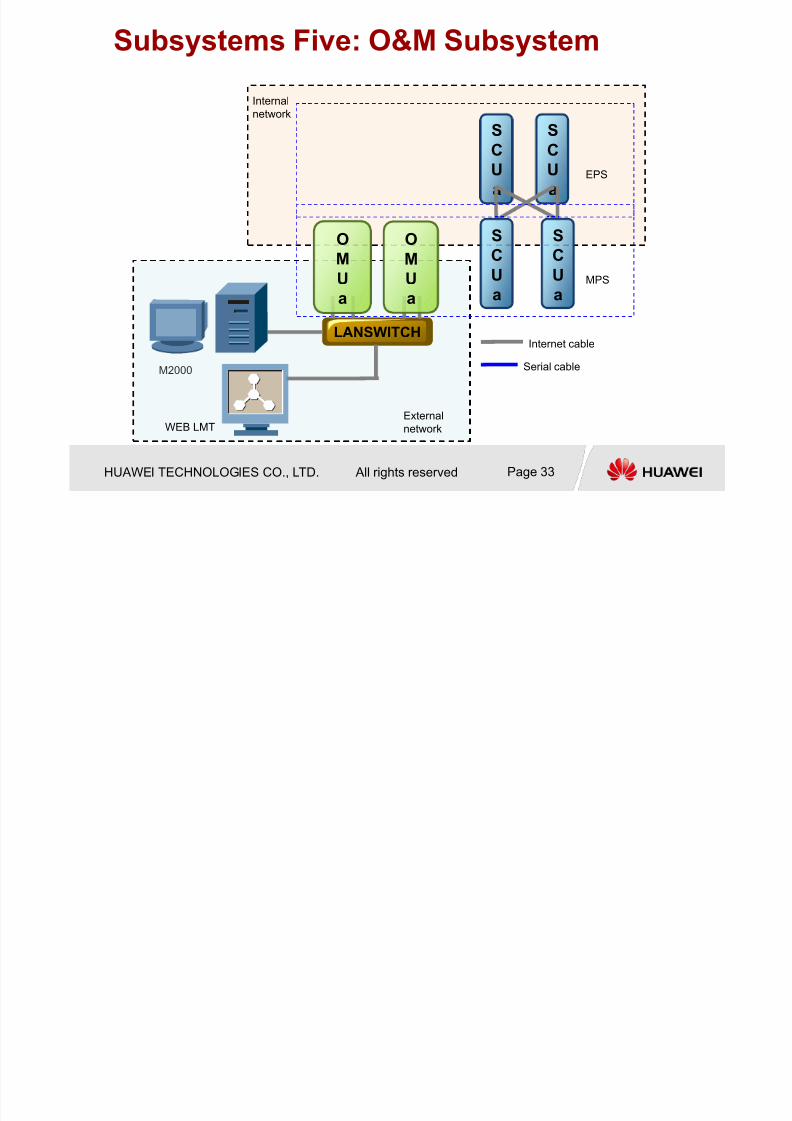
M2000
S
C
U
a
S
C
U
a
LANSWITCH
OM
U
a
OM
U
a
SC
U
a
SC
U
a
WEB LMTExternal
network
MPS
Internal
network
EPS
Internet cable
Serial cable
Subsystems Five: O&M Subsystem
B d I d i OMU
7/27/2019 BSC6900V900R011 GO Hardware Structure and System Description
http://slidepdf.com/reader/full/bsc6900v900r011-go-hardware-structure-and-system-description 34/54
HUAWEI TECHNOLOGIES CO., LTD. All rights reserved Page 34
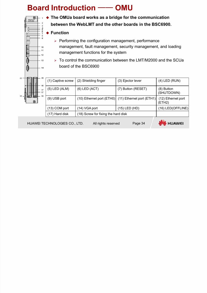
Board Introduction—— OMU The OMUa board works as a bridge for the communication
between the WebLMT and the other boards in the BSC6900.
Function
Performing the configuration management, performance
management, fault management, security management, and loading
management functions for the system
To control the communication between the LMT/M2000 and the SCUaboard of the BSC6900
(1) Captive screw (2) Shielding finger (3) Ejector lever (4) LED (RUN)
(5) LED (ALM) (6) LED (ACT) (7) Button (RESET) (8) Button
(SHUTDOWN)
(9) USB port (10) Ethernet port (ETH0) (11) Ethernet port (ETH1) (12) Ethernet port
(ETH2)
(13) COM port (14) VGA port (15) LED (HD) (16) LED(OFFLINE)
(17) Hard disk (18) Screw for fixing the hard disk
7/27/2019 BSC6900V900R011 GO Hardware Structure and System Description
http://slidepdf.com/reader/full/bsc6900v900r011-go-hardware-structure-and-system-description 35/54
HUAWEI TECHNOLOGIES CO., LTD. All rights reserved Page 35
Chapter 2 BSC6900 Hardware Structure
2.1 Frame and Subrack
2.2 Board Introduction
2.3 Cable Introduction

7/27/2019 BSC6900V900R011 GO Hardware Structure and System Description
http://slidepdf.com/reader/full/bsc6900v900r011-go-hardware-structure-and-system-description 36/54
HUAWEI TECHNOLOGIES CO., LTD. All rights reserved Page 36
TNUa
(Active)
Board
Board
LVDS TDM path of backplane
Inter-TNUa Cable
TNUa
(Standby)
TNUa(Active) Board
Board TNUa(Standby)
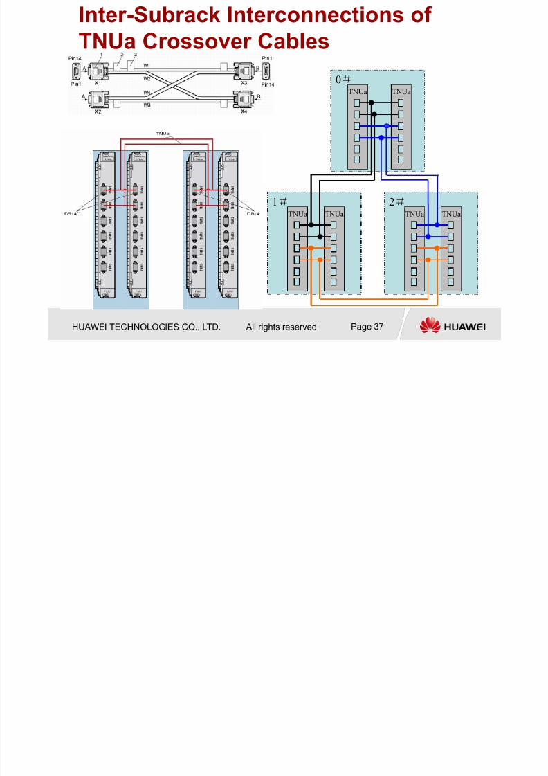
TDM Switching Subsystem Intra-Subrack: Other boards in the subrack connect with TNUa
(Active/Standby) through LVDS (Low Voltage Differential Signal) high
speed serial ports of backplane.
Inter-Subrack: TDM units of every subrack fully interconnected with
each other through TNUa crossover cables.
In full intra-subrack
interconnection, 2 cables
support 8K bandwidth.
Inter Subrack Interconnections of
7/27/2019 BSC6900V900R011 GO Hardware Structure and System Description
http://slidepdf.com/reader/full/bsc6900v900r011-go-hardware-structure-and-system-description 37/54
HUAWEI TECHNOLOGIES CO., LTD. All rights reserved Page 37
Inter-Subrack Interconnections of
TNUa Crossover Cables
1#
0# TNUa TNUa
TNUa TNUa
2# TNUa TNUa
7/27/2019 BSC6900V900R011 GO Hardware Structure and System Description
http://slidepdf.com/reader/full/bsc6900v900r011-go-hardware-structure-and-system-description 38/54
HUAWEI TECHNOLOGIES CO., LTD. All rights reserved Page 38
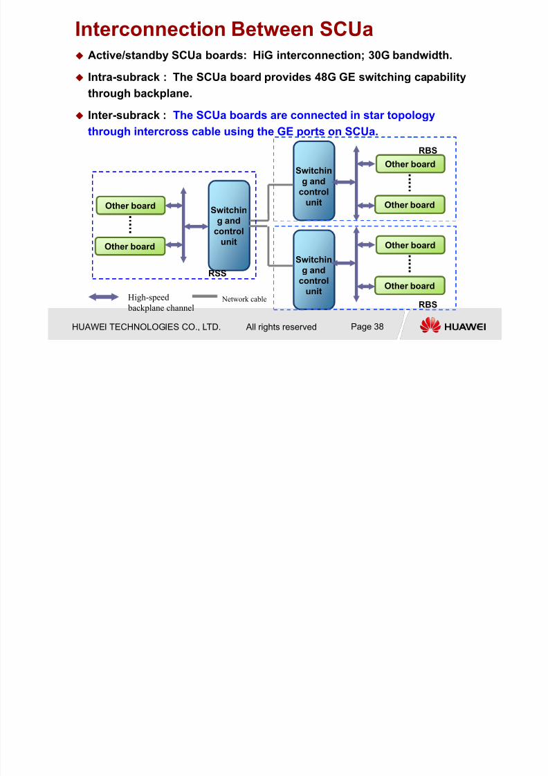
Interconnection Between SCUa Active/standby SCUa boards: HiG interconnection; 30G bandwidth.
Intra-subrack : The SCUa board provides 48G GE switching capabilitythrough backplane.
Inter-subrack : The SCUa boards are connected in star topology
through intercross cable using the GE ports on SCUa.
Switchin
g and
control
unit
Other board
Other board
Other board
Other board
Other board
Other board
Switchin
g and
control
unit
Switchin
g and
control
unit
RSS
RBS
RBS
High-speed
backplane channel Network cable

7/27/2019 BSC6900V900R011 GO Hardware Structure and System Description
http://slidepdf.com/reader/full/bsc6900v900r011-go-hardware-structure-and-system-description 39/54
HUAWEI TECHNOLOGIES CO., LTD. All rights reserved Page 39
The Physical Cable Between Subracks SCUa in MPS subrack
GE0~7 interconnect with EPS, open the port by MML command.
SCUa in EPS subrack
GE0~1 interconnect with MPS
7/27/2019 BSC6900V900R011 GO Hardware Structure and System Description
http://slidepdf.com/reader/full/bsc6900v900r011-go-hardware-structure-and-system-description 40/54
HUAWEI TECHNOLOGIES CO., LTD. All rights reserved Page 40
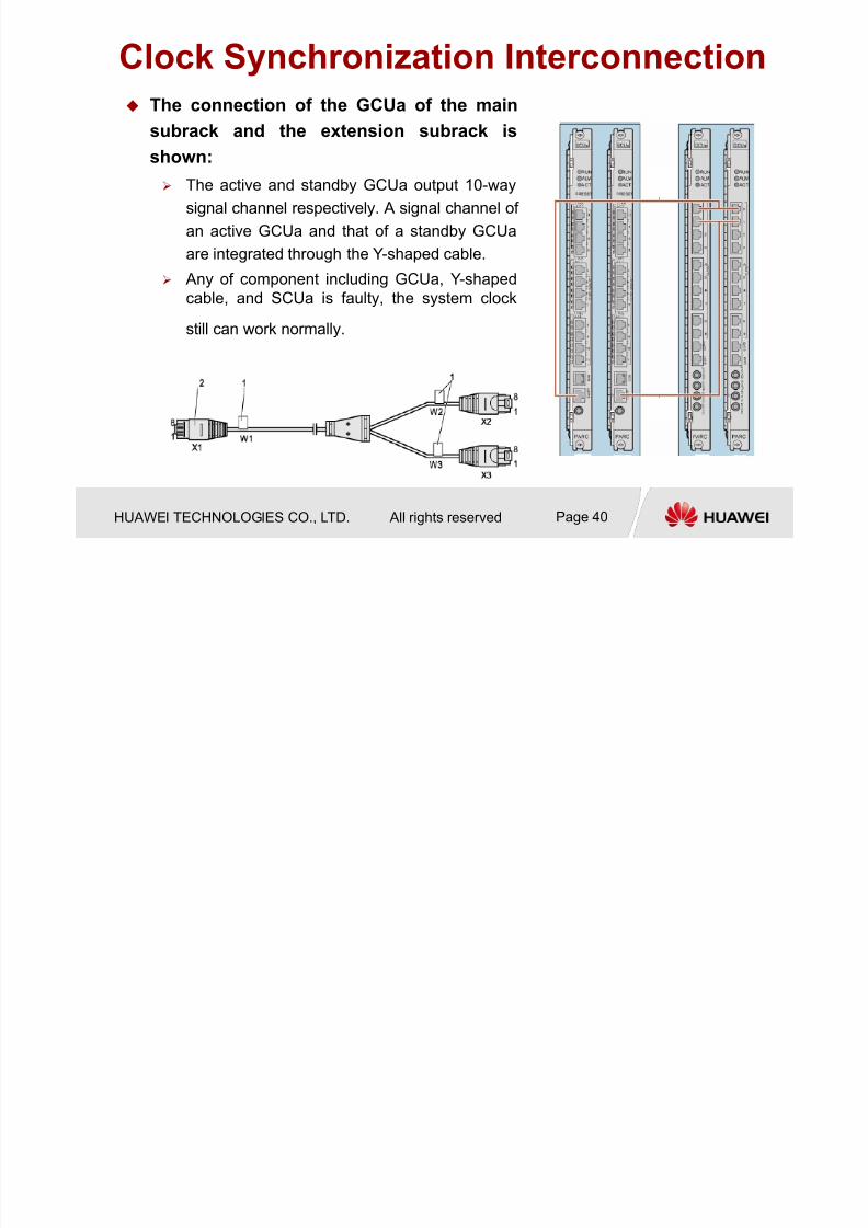
Clock Synchronization Interconnection
The connection of the GCUa of the main
subrack and the extension subrack isshown:
The active and standby GCUa output 10-way
signal channel respectively. A signal channel of
an active GCUa and that of a standby GCUa
are integrated through the Y-shaped cable. Any of component including GCUa, Y-shaped
cable, and SCUa is faulty, the system clock
still can work normally.
7/27/2019 BSC6900V900R011 GO Hardware Structure and System Description
http://slidepdf.com/reader/full/bsc6900v900r011-go-hardware-structure-and-system-description 41/54
HUAWEI TECHNOLOGIES CO., LTD. All rights reserved Page 41
Chapter 1 BSC6900 System Description
Chapter 2 BSC6900 Hardware Structure
Chapter 3 BSC6900 Signal Flow
Chapter 4 BSC6900 Typical Configuration

7/27/2019 BSC6900V900R011 GO Hardware Structure and System Description
http://slidepdf.com/reader/full/bsc6900v900r011-go-hardware-structure-and-system-description 42/54
HUAWEI TECHNOLOGIES CO., LTD. All rights reserved Page 42
GSM CS Signal Flow
Abis over TDM+A over TDM
7/27/2019 BSC6900V900R011 GO Hardware Structure and System Description
http://slidepdf.com/reader/full/bsc6900v900r011-go-hardware-structure-and-system-description 43/54
HUAWEI TECHNOLOGIES CO., LTD. All rights reserved Page 43
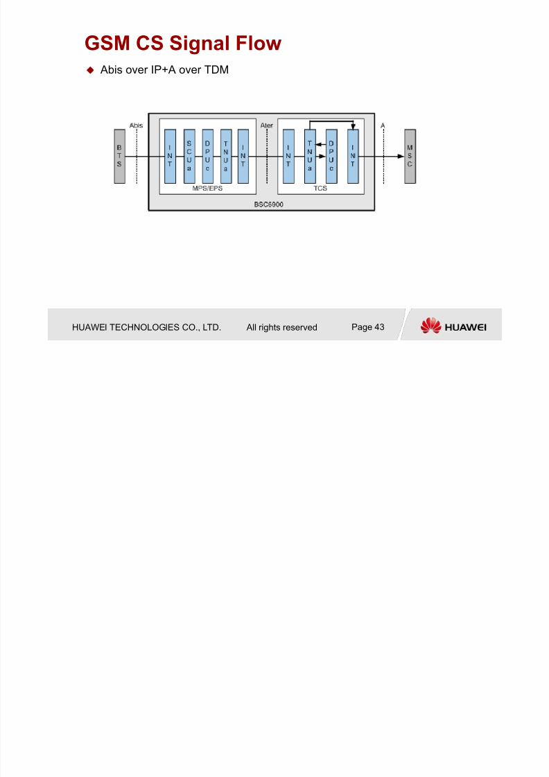
GSM CS Signal Flow Abis over IP+A over TDM
7/27/2019 BSC6900V900R011 GO Hardware Structure and System Description
http://slidepdf.com/reader/full/bsc6900v900r011-go-hardware-structure-and-system-description 44/54
HUAWEI TECHNOLOGIES CO., LTD. All rights reserved Page 44
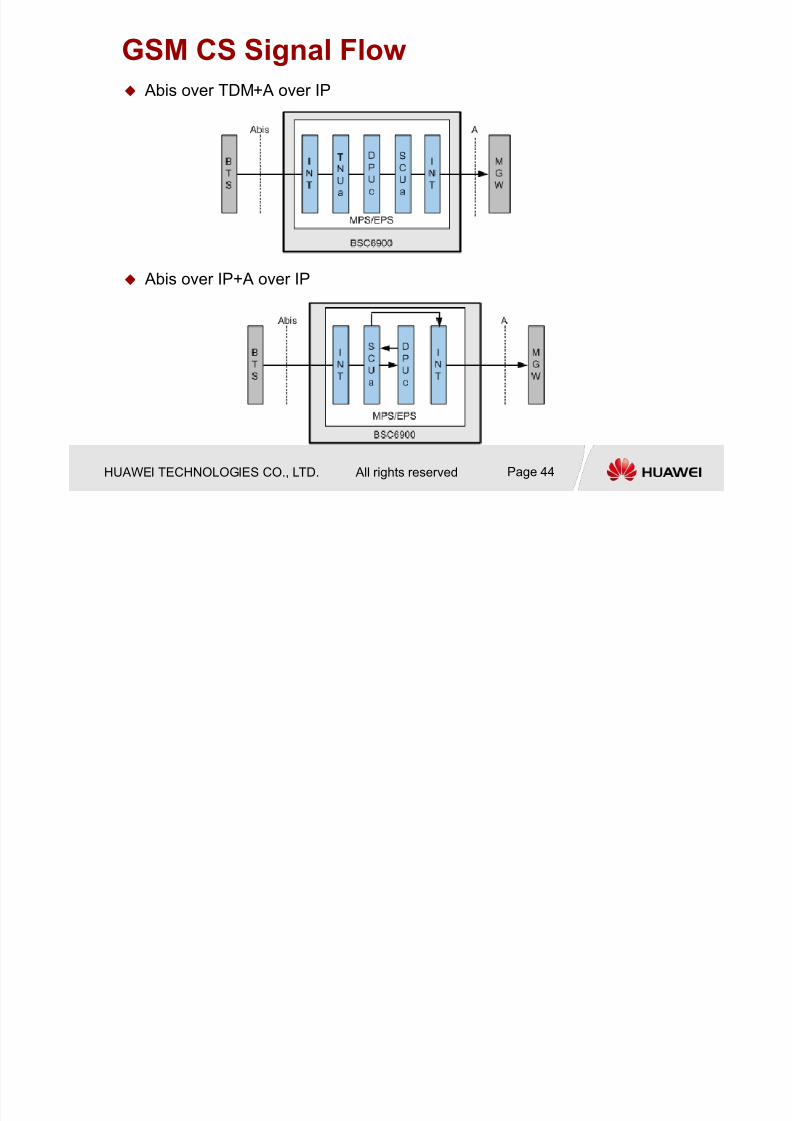
GSM CS Signal Flow
Abis over TDM+A over IP
Abis over IP+A over IP
7/27/2019 BSC6900V900R011 GO Hardware Structure and System Description
http://slidepdf.com/reader/full/bsc6900v900r011-go-hardware-structure-and-system-description 45/54
HUAWEI TECHNOLOGIES CO., LTD. All rights reserved Page 45
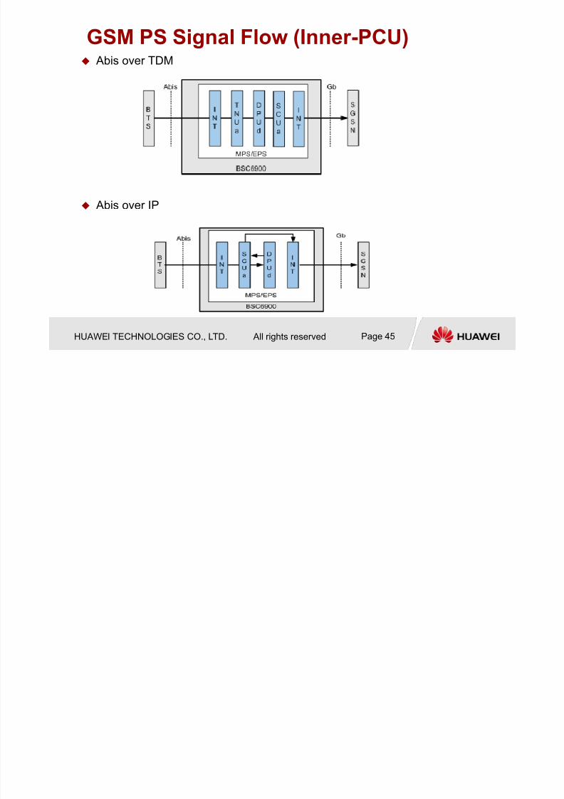
GSM PS Signal Flow (Inner-PCU) Abis over TDM
Abis over IP

7/27/2019 BSC6900V900R011 GO Hardware Structure and System Description
http://slidepdf.com/reader/full/bsc6900v900r011-go-hardware-structure-and-system-description 46/54
HUAWEI TECHNOLOGIES CO., LTD. All rights reserved Page 46
Signaling Flow on the A Interface Abis over TDM+A over TDM
the signaling processing board XPUa processes the signalingaccording to the MTP3, SCCP, and BSSAP protocols.

7/27/2019 BSC6900V900R011 GO Hardware Structure and System Description
http://slidepdf.com/reader/full/bsc6900v900r011-go-hardware-structure-and-system-description 47/54
HUAWEI TECHNOLOGIES CO., LTD. All rights reserved Page 47
Signaling Flow on the Abis Interface Abis over TDM/IP/HDLC

7/27/2019 BSC6900V900R011 GO Hardware Structure and System Description
http://slidepdf.com/reader/full/bsc6900v900r011-go-hardware-structure-and-system-description 48/54
HUAWEI TECHNOLOGIES CO., LTD. All rights reserved Page 48
Signaling Flow on the Gb Interface
Gb Over IP
the signaling processing board processes the signalingaccording to the NS and BSSGP protocols. Then, the signaling
is transmitted to the Gb interface board through the SCUa
board.
The Gb interface board processes the signaling according to
the IP or FR protocol. Then, the signaling is transmitted to the
SGSN over the Gb interface.

7/27/2019 BSC6900V900R011 GO Hardware Structure and System Description
http://slidepdf.com/reader/full/bsc6900v900r011-go-hardware-structure-and-system-description 49/54
HUAWEI TECHNOLOGIES CO., LTD. All rights reserved Page 49
OM Signal Flow
7/27/2019 BSC6900V900R011 GO Hardware Structure and System Description
http://slidepdf.com/reader/full/bsc6900v900r011-go-hardware-structure-and-system-description 50/54
HUAWEI TECHNOLOGIES CO., LTD. All rights reserved Page 50
Chapter 1 BSC6900 System Description
Chapter 2 BSC6900 Hardware Structure
Chapter 3 BSC6900 Signal Flow
Chapter 4 BSC6900 Typical Configuration
S ifi ti f th B d
7/27/2019 BSC6900V900R011 GO Hardware Structure and System Description
http://slidepdf.com/reader/full/bsc6900v900r011-go-hardware-structure-and-system-description 51/54
HUAWEI TECHNOLOGIES CO., LTD. All rights reserved Page 51
Specification of the Board
XPUa/XPUb
350TRX/XPUa 640TRX/XPUb
No. of XPUa=TRX No./350TRX No. of XPUb=TRX No./640TRX
Typical

7/27/2019 BSC6900V900R011 GO Hardware Structure and System Description
http://slidepdf.com/reader/full/bsc6900v900r011-go-hardware-structure-and-system-description 52/54
HUAWEI TECHNOLOGIES CO., LTD. All rights reserved Page 52
Typical
Configuration
Parameter Description
Typical

7/27/2019 BSC6900V900R011 GO Hardware Structure and System Description
http://slidepdf.com/reader/full/bsc6900v900r011-go-hardware-structure-and-system-description 53/54
HUAWEI TECHNOLOGIES CO., LTD. All rights reserved Page 53
Typical
Configuration Parameter Description

7/27/2019 BSC6900V900R011 GO Hardware Structure and System Description
http://slidepdf.com/reader/full/bsc6900v900r011-go-hardware-structure-and-system-description 54/54
谢谢
www.huawei.com