Embed Size (px)
DESCRIPTION
Normative
Citation preview
BS EN 15512:2009
ICS 53.080
NO COPYING WITHOUT BSI PERMISSION EXCEPT AS PERMITTED BY COPYRIGHT LAW
BRITISH STANDARD
Steel static storagesystems — Adjustablepallet racking systems— Principles forstructural design
This British Standard was published under the authority of the Standards Policy and Strategy Committee on 31 October 2009© BSI 2009
ISBN 978 0 580 57183 1
Amendments/corrigenda issued since publication
Date Comments
BS EN 15512:2009
National foreword
This British Standard is the UK implementation of EN 15512:2009.
The UK participation in its preparation was entrusted to TechnicalCommittee MHE/8, Steel shelving, bins and lockers.
A list of organizations represented on this committee can be obtained onrequest to its secretary.
BSI, as a member of CEN, is obliged to publish BS EN 15512 as aBritish Standard. However, attention is drawn to the fact that duringthe development of this European Standard, the UK committee votedagainst its approval as a European Standard.
The UK committee considers that this standard is too complex overall for use by the small and medium sized enterprises that make up the majority of UK suppliers of this material. In addition, the UK committee would like users to be aware that the sway imperfection formula (see Subclause 5.3.2) originates from the structural steel industry where tolerances are much lower than those routinely achieved in the mirror industry, and where a typical building comprises of three or four levels and ten or so bays, as compared to structures in the mirror industry which normally have more levels and certainly many more bays
This publication does not purport to include all the necessary provisionsof a contract. Users are responsible for its correct application.
Compliance with a British Standard cannot confer immunityfrom legal obligations.
BS EN 15512:2009
EUROPEAN STANDARD
NORME EUROPÉENNE
EUROPÄISCHE NORM
EN 15512
March 2009
ICS 53.080
English Version
Steel static storage systems - Adjustable pallet racking systems- Principles for structural design
Systèmes de stockage statiques en acier - Systèmes derayonnages à palettes réglables - Principes applicables au
calcul des structures
Ortsfeste Regalsysteme aus Stahl - VerstellbarePalettenregale - Grundlagen der statischen Bemessung
This European Standard was approved by CEN on 17 January 2009.
CEN members are bound to comply with the CEN/CENELEC Internal Regulations which stipulate the conditions for giving this EuropeanStandard the status of a national standard without any alteration. Up-to-date lists and bibliographical references concerning such nationalstandards may be obtained on application to the CEN Management Centre or to any CEN member.
This European Standard exists in three official versions (English, French, German). A version in any other language made by translationunder the responsibility of a CEN member into its own language and notified to the CEN Management Centre has the same status as theofficial versions.
CEN members are the national standards bodies of Austria, Belgium, Bulgaria, Cyprus, Czech Republic, Denmark, Estonia, Finland,France, Germany, Greece, Hungary, Iceland, Ireland, Italy, Latvia, Lithuania, Luxembourg, Malta, Netherlands, Norway, Poland, Portugal,Romania, Slovakia, Slovenia, Spain, Sweden, Switzerland and United Kingdom.
EUROPEAN COMMITTEE FOR STANDARDIZATIONC O M I T É E U R O P É E N D E N O R M A LI S A T I O NEUR OP ÄIS C HES KOM ITEE FÜR NOR M UNG
Management Centre: Avenue Marnix 17, B-1000 Brussels
© 2009 CEN All rights of exploitation in any form and by any means reservedworldwide for CEN national Members.
Ref. No. EN 15512:2009: E
BS EN 15512:2009EN 15512:2009 (E)
2
Contents Page
Foreword ..............................................................................................................................................................6 Introduction .........................................................................................................................................................7 1 Scope ......................................................................................................................................................9 2 Normative references ............................................................................................................................9 3 Terms and definitions ........................................................................................................................ 10 4 Symbols ............................................................................................................................................... 11 5 Basis of design ................................................................................................................................... 15 5.1 Requirements ...................................................................................................................................... 15 5.1.1 Basic requirements............................................................................................................................. 15 5.1.2 Un-braced racking systems ............................................................................................................... 15 5.1.3 Braced racking systems .................................................................................................................... 17 5.1.4 Design working life ............................................................................................................................. 19 5.1.5 Floor tolerances and deformations................................................................................................... 19 5.2 Methods of design .............................................................................................................................. 19 5.2.1 General ................................................................................................................................................. 19 5.2.2 Ultimate limit state .............................................................................................................................. 19 5.2.3 Serviceability limit state ..................................................................................................................... 20 5.3 Imperfections ...................................................................................................................................... 20 5.3.1 General ................................................................................................................................................. 20 5.3.2 Sway frame imperfections in un-braced systems ........................................................................... 20 5.3.3 Bracing system imperfections .......................................................................................................... 21 5.3.4 Imperfections in racks partially braced in the down-aisle direction ............................................. 23 5.3.5 Member imperfections ....................................................................................................................... 23 6 Actions and combinations of actions ............................................................................................... 23 6.1 General ................................................................................................................................................. 23 6.2 Permanent actions .............................................................................................................................. 24 6.2.1 General ................................................................................................................................................. 24 6.2.2 Weights of materials and construction ............................................................................................ 24 6.3 Variable actions .................................................................................................................................. 24 6.3.1 General ................................................................................................................................................. 24 6.3.2 Unit loads to be stored ....................................................................................................................... 24 6.3.3 Vertical placement loads .................................................................................................................... 25 6.3.4 Horizontal placement loads ............................................................................................................... 26 6.3.5 Effects of rack-guided equipment ..................................................................................................... 27 6.3.6 Floor and walkway loads (see also EN 1991-1-1) ............................................................................ 29 6.3.7 Actions arising from installation ....................................................................................................... 30 6.4 Actions due to impact (accidental loads) ......................................................................................... 30 6.4.1 General ................................................................................................................................................. 30 6.4.2 Accidental vertical actions ................................................................................................................ 30 6.4.3 Accidental horizontal load ................................................................................................................. 31 6.5 Wind loads ........................................................................................................................................... 31 6.6 Snow loads .......................................................................................................................................... 31 6.7 Seismic actions ................................................................................................................................... 32 7 Partial factors and combination rules .............................................................................................. 32 7.1 General ................................................................................................................................................. 32 7.2 Combinations of actions for the ultimate limit state ....................................................................... 32 7.3 Combination of actions for serviceability limit states .................................................................... 32 7.4 Load factors ........................................................................................................................................ 33
BS EN 15512:2009EN 15512:2009 (E)
3
7.5 Material factors .................................................................................................................................... 34 7.6 Stability against overturning .............................................................................................................. 34 7.7 Racks braced against the building structure ................................................................................... 35 8 Steel ...................................................................................................................................................... 35 8.1 General ................................................................................................................................................. 35 8.1.1 Preliminary considerations ................................................................................................................ 35 8.1.2 Material properties .............................................................................................................................. 35 8.1.3 Design values of material coefficients (general mechanical properties) ...................................... 35 8.1.4 Steels with no guaranteed mechanical properties .......................................................................... 36 8.1.5 Untested steels .................................................................................................................................... 36 8.2 Average yield strength of sections .................................................................................................... 36 8.3 Special selection of production material .......................................................................................... 36 8.4 Fracture toughness ............................................................................................................................. 37 8.5 Dimensional tolerances ...................................................................................................................... 37 8.5.1 General ................................................................................................................................................. 37 8.5.2 Thickness of material .......................................................................................................................... 37 8.5.3 Tolerances on thickness..................................................................................................................... 37 8.5.4 Width and depth of a cold-formed section ....................................................................................... 37 8.5.5 Member straightness .......................................................................................................................... 38 8.5.6 Twist ...................................................................................................................................................... 38 8.5.7 Tolerances with regard to design and assembly ............................................................................. 38 8.6 Bracing eccentricities ......................................................................................................................... 39 8.7 Eccentricities between beams and uprights .................................................................................... 40 8.8 Requirements for beam connector locks .......................................................................................... 41 8.9 Durability .............................................................................................................................................. 41 9 Structural analysis .............................................................................................................................. 41 9.1 Structural modelling for analysis and basic assumption ............................................................... 41 9.2 Calculation of section properties ...................................................................................................... 41 9.2.1 General ................................................................................................................................................. 41 9.2.2 Effect of corner radii ........................................................................................................................... 42 9.2.3 Effect of perforations .......................................................................................................................... 42 9.2.4 Effect of cross-section distortion ...................................................................................................... 43 9.2.5 Effect of local buckling ....................................................................................................................... 44 9.3 Beams ................................................................................................................................................... 45 9.3.1 General ................................................................................................................................................. 45 9.3.2 Moment of resistance of members not subject to lateral-torsional buckling ............................... 46 9.4 Design of beams .................................................................................................................................. 46 9.4.1 General ................................................................................................................................................. 46 9.4.2 Loads on beams .................................................................................................................................. 47 9.4.3 Design bending moments for beams ................................................................................................ 47 9.4.4 Design shear force for beams ............................................................................................................ 49 9.4.5 Deflection of beams ............................................................................................................................ 49 9.4.6 Beams as tie beams in braced pallet racks ...................................................................................... 50 9.4.7 Design resistance with respect to web crippling ............................................................................. 51 9.4.8 Design resistance with respect to shear forces ............................................................................... 51 9.4.9 Combined shear force, axial force and bending moment ............................................................... 51 9.4.10 Combined bending moment and web crippling ............................................................................... 51 9.5 Design of beam end connectors ........................................................................................................ 51 9.5.1 General ................................................................................................................................................. 51 9.5.2 Design bending moments in beam end connectors ........................................................................ 51 9.5.3 Design shear force for beam end connectors .................................................................................. 52 9.5.4 Design shear force and bending moment for beam end connectors ............................................ 52 9.6 Beams subject to bending and torsion ............................................................................................. 52 9.6.1 General ................................................................................................................................................. 52 9.6.2 Lateral torsional buckling of beams .................................................................................................. 53 9.7 Compression, tension and bending in members ............................................................................. 54 9.7.1 Non-perforated compression members ............................................................................................ 54 9.7.2 Perforated compression members .................................................................................................... 54
BS EN 15512:2009EN 15512:2009 (E)
4
9.7.3 Cross sectional verification ............................................................................................................... 55 9.7.4 Design strength with respect to flexural buckling .......................................................................... 55 9.7.5 Torsional and flexural-torsional buckling ........................................................................................ 62 9.7.6 Combined bending and axial loading ............................................................................................... 64 9.8 Design of splices ................................................................................................................................ 68 9.9 Design of base plates ......................................................................................................................... 69 9.9.1 General ................................................................................................................................................. 69 9.9.2 Effective area Abas for base plates ..................................................................................................... 69 9.10 Floor materials .................................................................................................................................... 70 9.10.1 Concrete floors ................................................................................................................................... 70 9.10.2 Bituminous floors ............................................................................................................................... 70 9.10.3 Other floor materials .......................................................................................................................... 71 9.10.4 Design of anchorages ........................................................................................................................ 71 9.11 Design of run spacers ........................................................................................................................ 72 10 Global analysis of beam pallet racks ................................................................................................ 72 10.1 General considerations ...................................................................................................................... 72 10.1.1 General ................................................................................................................................................. 72 10.1.2 Two dimensional analysis ................................................................................................................. 73 10.1.3 Advanced three-dimensional analysis ............................................................................................. 73 10.2 Design procedure ............................................................................................................................... 73 10.2.1 Actions ................................................................................................................................................. 73 10.2.2 Procedure ............................................................................................................................................ 73 10.2.3 Analysis of braced and un-braced racks in the down-aisle direction ........................................... 76 10.2.4 Moment-rotation characteristics of beam end connectors ............................................................ 78 10.2.5 Moment-rotation characteristics of the connection to the floor .................................................... 78 10.3 Analysis of braced and un-braced racks in the cross-aisle direction ........................................... 79 10.3.1 General ................................................................................................................................................. 79 10.3.2 Out of plane stability .......................................................................................................................... 79 10.3.3 Frame classification ........................................................................................................................... 79 10.4 Methods of global analysis ................................................................................................................ 81 10.5 Simplified methods of analysis for stability in the cross-aisle direction...................................... 83 10.6 Design of uprights .............................................................................................................................. 83 10.6.1 General ................................................................................................................................................. 83 10.6.2 Design axial forces and bending moments ..................................................................................... 83 11 Serviceability limit states ................................................................................................................... 83 11.1 General ................................................................................................................................................. 83 11.2 Serviceability limit states for racking ............................................................................................... 83 12 Marking and labelling ......................................................................................................................... 84 12.1 Identification of performance of rack installations ......................................................................... 84 13 Test methods and evaluation of results ........................................................................................... 84 13.1 General ................................................................................................................................................. 84 13.2 Requirements for tests ....................................................................................................................... 85 13.2.1 Equipment ........................................................................................................................................... 85 13.2.2 Support conditions ............................................................................................................................. 85 13.2.3 Application of the load ....................................................................................................................... 86 13.2.4 Increments of the test load ................................................................................................................ 86 13.2.5 Assembly of test specimens ............................................................................................................. 86 13.2.6 Test reports ......................................................................................................................................... 86 13.3 Interpretation of test results .............................................................................................................. 87 13.3.1 Definition of failure load ..................................................................................................................... 87 13.3.2 Corrections to test results ................................................................................................................. 87 13.3.3 Derivation of characteristic values ................................................................................................... 87 13.3.4 Characteristic values for a family of tests ....................................................................................... 88 13.3.5 Corrections to failure loads or moments ......................................................................................... 89 Annex A (normative) Testing .......................................................................................................................... 90 A.1 Materials tests ..................................................................................................................................... 90 A.1.1 Tensile test .......................................................................................................................................... 90
BS EN 15512:2009EN 15512:2009 (E)
5
A.1.2 Bend tests ............................................................................................................................................ 90 A.2 Tests on components and connections ............................................................................................ 91 A.2.1 Stub column compression test .......................................................................................................... 91 A.2.2 Compression tests on uprights - Checks for the effects of distortional buckling ......................... 93 A.2.3 Compression tests on uprights - Determination of buckling curves ............................................. 94 A.2.4 Bending tests on beam end connectors ........................................................................................... 98 A.2.5 Looseness tests on beam end connectors..................................................................................... 104 A.2.6 Shear tests on beam end connectors and connector locks ......................................................... 106 A.2.7 Tests on floor connections............................................................................................................... 108 A.2.8 Tests for the shear stiffness of upright frames .............................................................................. 111 A.2.9 Bending tests on upright sections .................................................................................................. 113 A.2.10 Bending tests on beams ................................................................................................................... 115 A.2.11 Tests on upright splices ................................................................................................................... 116 Annex B (informative) Amplified sway method for down-aisle stability analysis .................................... 119 B.1 General ............................................................................................................................................... 119 B.2 Linear elastic analysis ...................................................................................................................... 120 B.3 Elastic critical value .......................................................................................................................... 120 B.4 Amplification factor ........................................................................................................................... 120 Annex C (informative) Approximate equations for the design of a regular storage rack in the
down-aisle direction .......................................................................................................................... 121 C.1 Approximate equation for regular construction ............................................................................ 121 C.2 Additional bending moments due to pattern loading .................................................................... 123 C.3 Design Moments ................................................................................................................................ 123 C.4 Design loads in outer columns ........................................................................................................ 124 Annex D (informative) Background to the acceptance of materials of low fu/fy ratio (cold reduced
steel) ................................................................................................................................................... 125 Annex E (informative) Position inaccuracies ............................................................................................... 126 Annex F (informative) Equivalent beam loads ............................................................................................. 127 Annex G (informative) Simplified method for cross-aisle stability analysis in circumstances where
there is uniform distribution of compartment loads over the height of the upright frame ....... 129 G.1 General ............................................................................................................................................... 129 G.2 Global buckling of upright frames ................................................................................................... 129 G.3 Shear stiffness of upright frame ...................................................................................................... 130 G.4 Amplification factor β ........................................................................................................................ 130 Annex H (informative) Factory production control (FPC) ........................................................................... 133 H.1 General ............................................................................................................................................... 133 H.2 Frequency of tests ............................................................................................................................. 133 H.3 Bending tests on beam end connectors ......................................................................................... 133 H.4 Bend tests .......................................................................................................................................... 134 Annex I (informative) A–deviations ............................................................................................................... 135 I.1 Dutch national legislative deviations .............................................................................................. 135 I.2 German national legislative deviations ........................................................................................... 135 Bibliography .................................................................................................................................................... 137

BS EN 15512:2009EN 15512:2009 (E)
6
Foreword
This document (EN 15512:2009) has been prepared by Technical Committee CEN/TC 344 “Steel static storage systems”, the secretariat of which is held by UNI.
This European Standard shall be given the status of a national standard, either by publication of an identical text or by endorsement, at the latest by September 2009, and conflicting national standards shall be withdrawn at the latest by September 2009.
Attention is drawn to the possibility that some of the elements of this document may be the subject of patent rights. CEN [and/or CENELEC] shall not be held responsible for identifying any or all such patent rights.
According to the CEN/CENELEC Internal Regulations, the national standards organizations of the following countries are bound to implement this European Standard: Austria, Belgium, Bulgaria, Cyprus, Czech Republic, Denmark, Estonia, Finland, France, Germany, Greece, Hungary, Iceland, Ireland, Italy, Latvia, Lithuania, Luxembourg, Malta, Netherlands, Norway, Poland, Portugal, Romania, Slovakia, Slovenia, Spain, Sweden, Switzerland and the United Kingdom.

BS EN 15512:2009EN 15512:2009 (E)
7
Introduction
0.1 Racking
Racking systems are load bearing structures for the storage and retrieval of goods in warehouses. The goods to be stored are generally on pallets or in box-containers.
Racking is constructed from steel components including upright frames, beams and decking. Special beam to column (upright) connections and bracing systems are utilised, in order to achieve a three dimensional steel ‘sway’ or ‘braced’ structure with “aisles” to enable order pickers, industrial trucks or stacker cranes to reach the storage positions. Although components are standardised they are only standard to each manufacturer. These components differ from traditional column and beam structures in the following regard.
1) Continuous perforated uprights.
2) Hook-in connections.
3) Structural components for racking generally consist of cold formed thin gauge members.
0.2 Requirement for EN Standards for racking and shelving in addition to the Eurocodes
Because of the differences in shape of structural components, detailing and connection type's additional technical information to the Eurocodes are required, in order to have reliable state of the art guidance for the practicing designer involved in designing racking.
The scope of CEN/TC 344 is to establish European Standards providing guidance for the specification, design, methods of installation, accuracy of build and guidance for the user on the safe use of steel static storage systems.
This, together with the need for harmonised design rules was the reason that the European Racking Federation ERF / FEM Racking and Shelving has taken the initiative for CEN/TC 344. CEN/TC 344 is in the course of preparation of a number of European Standards for specific types of racking and shelving and particular applications which exist as European Standards (EN) and working group activities (WG) as follows:
EN 15512: Steel static storage systems - Adjustable pallet racking systems - Principles for structural design.
EN 15620: Steel static storage systems - Adjustable pallet racking - Tolerances, deformations and clearances.
EN 15629: Steel static storage systems - The specification of storage equipment.
EN 15635: Steel static storage systems - The application and maintenance of storage equipment
WG 3c: Terms and Definitions.
WG 4:Technical Principles for the Design of Adjustable Drive-in and Drive-through Racking Systems.
WG 5a:Technical principles for the Design of Pallet Racking Systems in Seismic Regions.
WG 5b:Technical Principles for the Design of Drive-in and Drive-through Racking Systems in Seismic Regions.
WG 6:Technical Principles for the Design of Shelving Systems.
BS EN 15512:2009EN 15512:2009 (E)
8
WG 7:Technical Principles for the Design of Cantilever Racking Systems.
WG 8:Technical Principles for the Design of Mobile Racking Systems.
WG 9: Principles of Health and Safety during the installation of Racking Systems.
The intention is for these EN-Series “Racking and Shelving” to be published sequentially over a period of ten years.
In drafting these documents, liaisons with other CEN/TC's will occur as appropriate.
0.3 Liaison
CEN/TC 344 “Steel Storage Systems” liaise with CEN/TC 250 “Structural Eurocodes”, CEN/TC 135 “Execution of steel structures and aluminium structures” and CEN/TC 149 “Power-operated warehouse equipment”.
0.4 Racking and Shelving and Work Equipment regulations
Although racking is a load bearing structure, national regulatory requirements may require that racking be considered as ‘work equipment’ and therefore may be subject to the European Directive 89/391/EEC. This document is not a stand alone document and is intended to be used in conjunction with EN15620, EN 15629 and EN 15635.
0.5 Additional information specific to EN 15512
EN 15512 is intended to be used with EN 1990 – Basis of Structural Design, EN 1991 – Actions on structures, and EN 1993 for the Design of steel structures.
EN 1993-1 is the first of six parts of EN 1993 – Design of Steel Structures. It gives generic design rules intended to be used with the other parts EN 1993-2 to EN 1993-6. It also gives supplementary rules applicable only to buildings.
EN 1993-1 comprises eleven subparts EN 1993-1-1 to EN 1993-1-11, each addressing specific steel components, limit states or materials.
EN15512 may also be used for design cases not covered by the Eurocodes (other structures, other actions, other materials) serving as a reference document for other CEN TC´s concerning structural matters.
EN 15512 is intended for use by
committees drafting design related product, testing and execution standards,
designers and structural engineers,
relevant authorities.
Numerical values for partial factors and other reliability parameters are basic values that provide an acceptable level of reliability assuming an appropriate level of workmanship and quality management.
As part of the design process, reference to EN 15629 and EN 15635 shall be required to ensure that both specifier and designer are aware of the interface constraints in each other’s responsibility and to allow an effective design to be produced.
BS EN 15512:2009EN 15512:2009 (E)
9
1 Scope
This European Standard specifies the structural design requirements applicable to all types of adjustable beam pallet rack systems fabricated from steel members intended for the storage of unit loads and subject to predominantly static loads. Both un-braced and braced systems are included.
This European Standard gives guidelines for the design of clad rack buildings where requirements are not covered in EN 1993. The requirements of this European Standard also apply to ancillary structures, where rack components are employed as the main structural members.
This European Standard does not cover other generic types of storage structures. Specifically, this European Standard does not apply to mobile storage systems, drive-in, drive-through and cantilever racks or static steel shelving systems, nor does this European Standard establish specific design rules for the assessment of racking in seismic areas.
2 Normative references
The following referenced documents are indispensable for the application of this document. For dated references, only the edition cited applies. For undated references, the latest edition of the referenced document (including any amendments) applies.
EN 528, Rail dependent storage and retrieval equipment - Safety
EN 1990, Eurocode - Basis of structural design
EN 1991-1-1:2002, Eurocode 1: Actions on structures - Part 1-1: General actions - Densities, self-weight, imposed loads for buildings
EN 1993-1-1:2005, Eurocode 3: Design of steel structures - Part 1-1: General rules and rules for buildings
EN 1993-1-3:2006, Eurocode 3 - Design of steel structures - Part 1-3: General rules - Supplementary rules for cold-formed members and sheeting
EN 10002-1, Metallic materials - Tensile testing – Part1: Method of test at ambient temperature
EN 10143, Continuously hot-dipped coated steel sheet and strip - Tolerances on dimensions and shape
EN 10162, Cold rolled steel sections - Technical delivery conditions - Dimensional and cross-sectional tolerances
EN 10326, Continuous hot-dip coated strip and sheet of structural steels -Technical delivery conditions
EN 15620, Steel static storage systems - Adjustable pallet racking - Tolerances, deformations and clearances
EN 15629, Steel static storage systems - The specification of storage equipment
EN 15635, Steel static storage systems - The application and maintenance of storage equipment
prEN 15878, Steel static storage systems - Terms and definitions
EN ISO 7438, Metallic materials - Bend test (ISO 7438:2005)
EN ISO 9001, Quality management systems - Requirements (ISO 9001:2000)
ETAG No 001, Guideline for European Technical Approval of Metal Anchors for Use in Concrete
BS EN 15512:2009EN 15512:2009 (E)
10
3 Terms and definitions
For the purposes of this document, the following terms and definitions given in prEN 15878 apply.
3.1 accidental action action, usually of short duration but of significant magnitude, that is unlikely to occur on a given structure during the design working life
3.2 basic material flat steel sheets or coiled strip, possibly cold reduced from which the rack components are pressed or rolled
3.3 batch of steel quantity of steel, all to the same specification, produced by one supplier at one time
3.4 beam horizontal member linking adjacent frames and lying in the horizontal direction parallel to the operating aisle
3.5 beam end connector connector, welded to or otherwise formed as an integral part of the beams, which has hooks or other devices which engage in holes or slots in the upright
3.6 compartment load load which can be loaded into one compartment of a rack or shelving structure from one side
3.7 double entry rack run of racking accessible from two adjacent operating aisles connected by run spacers
3.8 global analysis determination of a consistent set of internal forces, moments and displacements that represent the entire three dimensional load bearing rack structure, which are in equilibrium with a particular set of actions on the structure
3.9 perforated member member with multiple holes regularly spaced along its length
3.10 placement load load caused by deposit and picking operations of a unit load into and out of the system, reflecting good practice
3.11 single entry rack run of racking accessible from a single operating aisle
3.12 spine bracing sway bracing in the vertical plane parallel to the main aisle of the rack, linking adjacent frames
BS EN 15512:2009EN 15512:2009 (E)
11
3.13 spring-back tendency of a cold-formed section to undergo spontaneous cross-sectional distortion when it is cut from a longer length
3.14 stiffened element stiffened element of a cross-section is a part of the cross-section which is connected to the remainder of the section along both longitudinal edges
3.15 sway horizontal displacement of structure in addition to any initial out of plumb
3.16 unit load individual stored item that can be placed or retrieved in one operation
3.17 un-stiffened element an un-stiffened element of a cross-section is a part of the cross-section which is connected to the remainder of the section along one longitudinal edge only
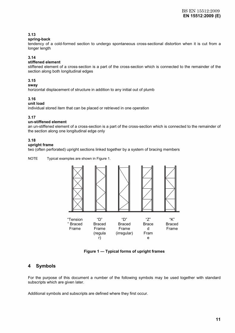
3.18 upright frame two (often perforated) upright sections linked together by a system of bracing members
NOTE Typical examples are shown in Figure 1.
“Tension” Braced Frame
“D” Braced Frame (regula
r)
“D” Braced Frame
(irregular)
“Z” Brace
d Fram
e
“K” Braced Frame
Figure 1 — Typical forms of upright frames
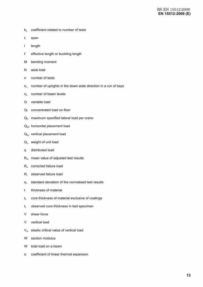
4 Symbols
For the purpose of this document a number of the following symbols may be used together with standard subscripts which are given later.
Additional symbols and subscripts are defined where they first occur.

BS EN 15512:2009EN 15512:2009 (E)
12
A symbol and subscript may have several meanings in this document.
In general primary symbols are not defined with all the standard subscripts with which they may be used.
A accidental action
A cross sectional area
Aeff effective cross sectional area
Ag gross cross sectional area
Aph accidental horizontal placement force
Apv accidental vertical placement force
b width of upright
bp notional plane width of element
E modulus of elasticity
e effective bearing width of base plate
e eccentricities
fck characteristic cylinder strength of concrete
ft observed yield strength in test specimen
fu ultimate strength
fy yield strength
fya average yield strength
fyb basic yield strength (=fy)
G shear modulus
Gk characteristic value of permanent loads (dead loads)
h storey height
I second moment of area
IT St Venant torsion constant
Iw warping constant
i radius of gyration
i0 polar radius of gyration
K effective length factor
kb stiffness of beam to column connector
BS EN 15512:2009EN 15512:2009 (E)
13
ks coefficient related to number of tests
L span
l length
ℓ effective length or buckling length
M bending moment
N axial load
n number of tests
nc number of uprights in the down aisle direction in a run of bays
ns number of beam levels
Q variable load
Qf concentrated load on floor
Qh maximum specified lateral load per crane
Qph horizontal placement load
Qpv vertical placement load
Qu weight of unit load
q distributed load
Rm mean value of adjusted test results
Rn corrected failure load
Rt observed failure load
sn standard deviation of the normalised test results
t thickness of material
tc core thickness of material exclusive of coatings
tt observed core thickness in test specimen
V shear force
V vertical load
Vcr elastic critical value of vertical load
W section modulus
W total load on a beam
α coefficient of linear thermal expansion

BS EN 15512:2009EN 15512:2009 (E)
14
α correction factor for yield strength
α imperfection factor
β beam coefficient
β correction factor for thickness
β amplification factor for second order effects
γ partial factor
γA partial factor for accidental loads
γf load factor
γG partial factor for permanent loads
γM material factor
γQ partial factor for variable loads
δ deflection
θ rotation
λ slenderness ratio
λ non-dimensional slenderness
υ Poisson’s ratio
ρ density
φ sway imperfection
φ 0 initial sway imperfection
φ l looseness of beam end connector
χ stress reduction factor for buckling
Subscripts
b buckling
c compression, capacity
cr critical
d design
db distortional buckling
FT flexural torsional

BS EN 15512:2009EN 15512:2009 (E)
15
g gross
i test number
k characteristic
LT lateral torsional
m mean value
n corrected value
Rd design resistance
Sd design strength
ser service
T torsional
t observed value at test
5 Basis of design
5.1 Requirements
5.1.1 Basic requirements
Pallet racks are standard products for which design by calculation alone may not be appropriate. Test procedures are therefore specified where current analytical methods are not given, or are not appropriate. The relevant test procedures are given in Annex A.
Except where specific requirements are given to the contrary, the design procedures in this document shall be in accordance with EN 1990, EN 1993-1-1 and EN 1993-1-3.
Design shall be carried out on the basis of the specified installation tolerances given in EN 15620 and the operational practice described in EN 15635.
For racking in seismic zones see bibliography, reference 3.
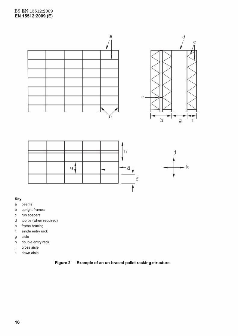
5.1.2 Un-braced racking systems
The configuration of a typical un-braced pallet rack is shown in Figure 2 in which the down-aisle stability is provided by the restraining effect of the beam end connectors. In the cross-aisle direction, stability is provided by the bracing in the frames which, in the case of the double entry rack shown, shall be linked together in the height by run spacers.
BS EN 15512:2009EN 15512:2009 (E)
16
d
h f
a
b
e
c
g
g
j
k
h
d
f
Key a beams b upright frames c run spacers d top tie (when required) e frame bracing f single entry rack g aisle h double entry rack j cross aisle k down aisle
Figure 2 — Example of an un-braced pallet racking structure
BS EN 15512:2009EN 15512:2009 (E)
17
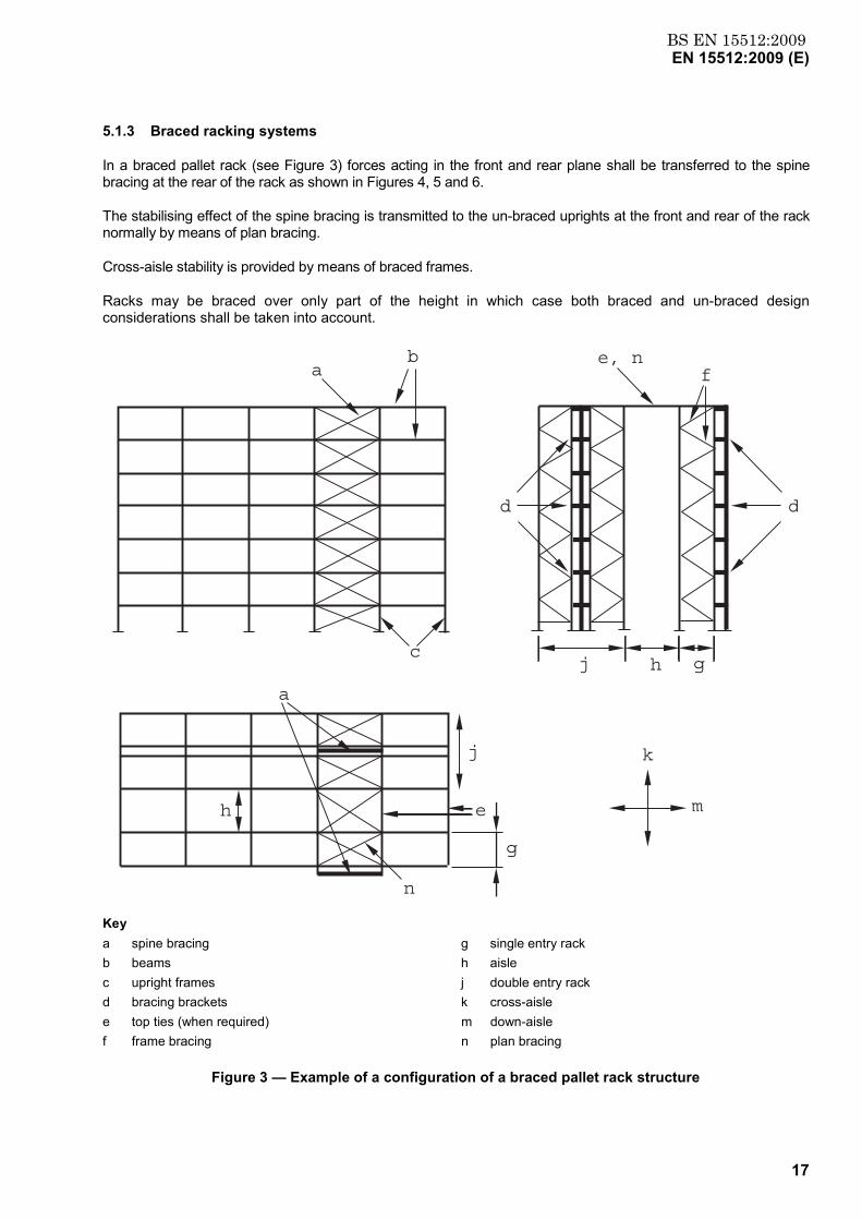
5.1.3 Braced racking systems
In a braced pallet rack (see Figure 3) forces acting in the front and rear plane shall be transferred to the spine bracing at the rear of the rack as shown in Figures 4, 5 and 6.
The stabilising effect of the spine bracing is transmitted to the un-braced uprights at the front and rear of the rack normally by means of plan bracing.
Cross-aisle stability is provided by means of braced frames.
Racks may be braced over only part of the height in which case both braced and un-braced design considerations shall be taken into account.
b
c
h
j
e
g
k
m
a
n
ae, n
f
j gh
d d
Key a spine bracing g single entry rack b beams h aisle c upright frames j double entry rack d bracing brackets k cross-aisle e top ties (when required) m down-aisle f frame bracing n plan bracing
Figure 3 — Example of a configuration of a braced pallet rack structure
BS EN 15512:2009EN 15512:2009 (E)
18
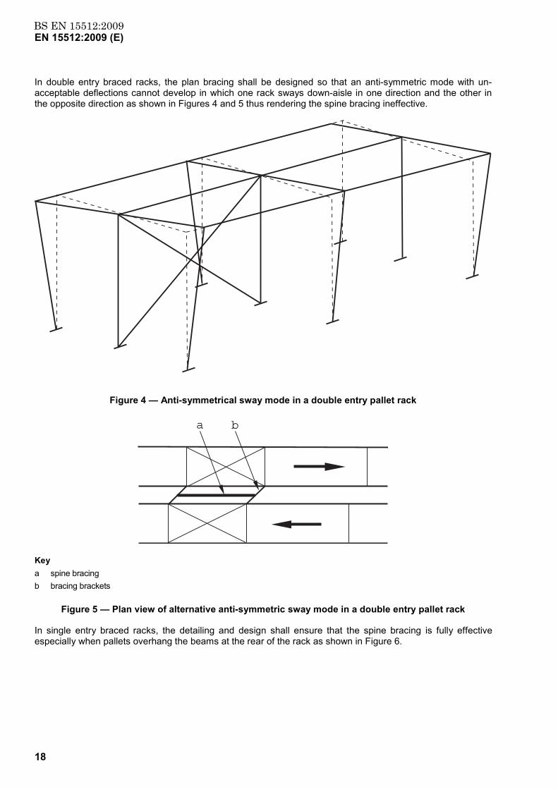
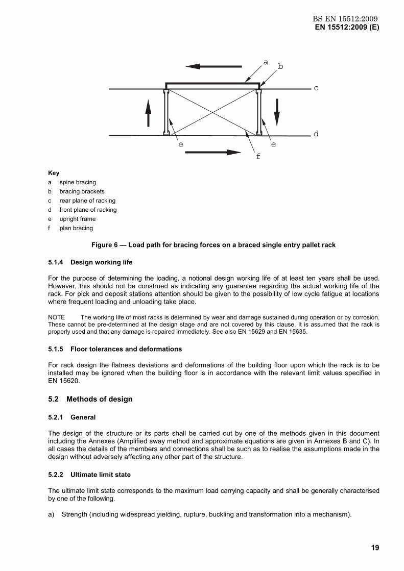
In double entry braced racks, the plan bracing shall be designed so that an anti-symmetric mode with un-acceptable deflections cannot develop in which one rack sways down-aisle in one direction and the other in the opposite direction as shown in Figures 4 and 5 thus rendering the spine bracing ineffective.
Figure 4 — Anti-symmetrical sway mode in a double entry pallet rack
a b
Key a spine bracing b bracing brackets
Figure 5 — Plan view of alternative anti-symmetric sway mode in a double entry pallet rack
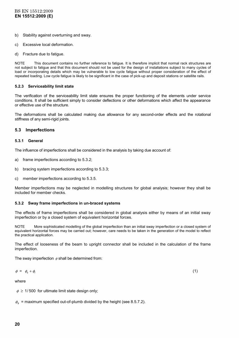
In single entry braced racks, the detailing and design shall ensure that the spine bracing is fully effective especially when pallets overhang the beams at the rear of the rack as shown in Figure 6.
BS EN 15512:2009EN 15512:2009 (E)
19
a
c
e
f
b
de
Key a spine bracing b bracing brackets c rear plane of racking d front plane of racking e upright frame f plan bracing
Figure 6 — Load path for bracing forces on a braced single entry pallet rack
5.1.4 Design working life
For the purpose of determining the loading, a notional design working life of at least ten years shall be used. However, this should not be construed as indicating any guarantee regarding the actual working life of the rack. For pick and deposit stations attention should be given to the possibility of low cycle fatigue at locations where frequent loading and unloading take place.
NOTE The working life of most racks is determined by wear and damage sustained during operation or by corrosion. These cannot be pre-determined at the design stage and are not covered by this clause. It is assumed that the rack is properly used and that any damage is repaired immediately. See also EN 15629 and EN 15635.
5.1.5 Floor tolerances and deformations
For rack design the flatness deviations and deformations of the building floor upon which the rack is to be installed may be ignored when the building floor is in accordance with the relevant limit values specified in EN 15620.
5.2 Methods of design
5.2.1 General
The design of the structure or its parts shall be carried out by one of the methods given in this document including the Annexes (Amplified sway method and approximate equations are given in Annexes B and C). In all cases the details of the members and connections shall be such as to realise the assumptions made in the design without adversely affecting any other part of the structure.
5.2.2 Ultimate limit state
The ultimate limit state corresponds to the maximum load carrying capacity and shall be generally characterised by one of the following.
a) Strength (including widespread yielding, rupture, buckling and transformation into a mechanism).
BS EN 15512:2009EN 15512:2009 (E)
20
b) Stability against overturning and sway.
c) Excessive local deformation.
d) Fracture due to fatigue.
NOTE This document contains no further reference to fatigue. It is therefore implicit that normal rack structures are not subject to fatigue and that this document should not be used for the design of installations subject to many cycles of load or incorporating details which may be vulnerable to low cycle fatigue without proper consideration of the effect of repeated loading. Low cycle fatigue is likely to be significant in the case of pick-up and deposit stations or satellite rails.
5.2.3 Serviceability limit state
The verification of the serviceability limit state ensures the proper functioning of the elements under service conditions. It shall be sufficient simply to consider deflections or other deformations which affect the appearance or effective use of the structure.
The deformations shall be calculated making due allowance for any second-order effects and the rotational stiffness of any semi-rigid joints.
5.3 Imperfections
5.3.1 General
The influence of imperfections shall be considered in the analysis by taking due account of:
a) frame imperfections according to 5.3.2;
b) bracing system imperfections according to 5.3.3;
c) member imperfections according to 5.3.5.
Member imperfections may be neglected in modelling structures for global analysis; however they shall be included for member checks.
5.3.2 Sway frame imperfections in un-braced systems
The effects of frame imperfections shall be considered in global analysis either by means of an initial sway imperfection or by a closed system of equivalent horizontal forces.
NOTE More sophisticated modelling of the global imperfection than an initial sway imperfection or a closed system of equivalent horizontal forces may be carried out; however, care needs to be taken in the generation of the model to reflect the practical application.
The effect of looseness of the beam to upright connector shall be included in the calculation of the frame imperfection.
The sway imperfection φ shall be determined from:
ls φφφ + = (1)
where
500/1 ≥φ for ultimate limit state design only;
sφ = maximum specified out-of-plumb divided by the height (see 8.5.7.2).
BS EN 15512:2009EN 15512:2009 (E)
21
lφ = looseness of beam-upright connector determined according to A.2.5
NOTE If the effect of the looseness of the beam to upright connector is included in the modelling of the connection used in the global analysis, lφ may be set equal to zero in the above equations.
These initial sway imperfections shall apply in all horizontal directions, but may only be considered in one direction at a time.
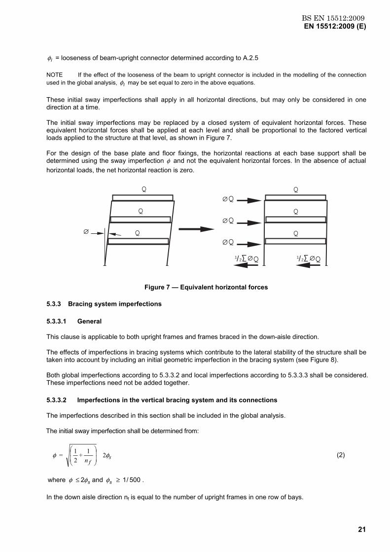
The initial sway imperfections may be replaced by a closed system of equivalent horizontal forces. These equivalent horizontal forces shall be applied at each level and shall be proportional to the factored vertical loads applied to the structure at that level, as shown in Figure 7.
For the design of the base plate and floor fixings, the horizontal reactions at each base support shall be determined using the sway imperfection φ and not the equivalent horizontal forces. In the absence of actual horizontal loads, the net horizontal reaction is zero.
Q
Q
Q
Q
Q
Q
Q
1/2 Q 1/2 Q
Q
Q
Figure 7 — Equivalent horizontal forces
5.3.3 Bracing system imperfections
5.3.3.1 General
This clause is applicable to both upright frames and frames braced in the down-aisle direction.
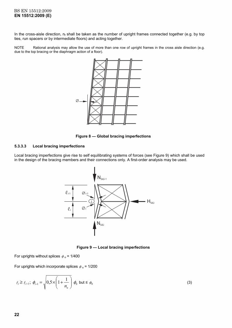
The effects of imperfections in bracing systems which contribute to the lateral stability of the structure shall be taken into account by including an initial geometric imperfection in the bracing system (see Figure 8).
Both global imperfections according to 5.3.3.2 and local imperfections according to 5.3.3.3 shall be considered. These imperfections need not be added together.
5.3.3.2 Imperfections in the vertical bracing system and its connections
The imperfections described in this section shall be included in the global analysis.
The initial sway imperfection shall be determined from:
sfn
φφ 2 1 + 21 =
(2)
500/1 and2 where ≥≤ ss φφφ .
In the down aisle direction nf is equal to the number of upright frames in one row of bays.
BS EN 15512:2009EN 15512:2009 (E)
22
In the cross-aisle direction, nf shall be taken as the number of upright frames connected together (e.g. by top ties, run spacers or by intermediate floors) and acting together.
NOTE Rational analysis may allow the use of more than one row of upright frames in the cross aisle direction (e.g. due to the top bracing or the diaphragm action of a floor).
Figure 8 — Global bracing imperfections
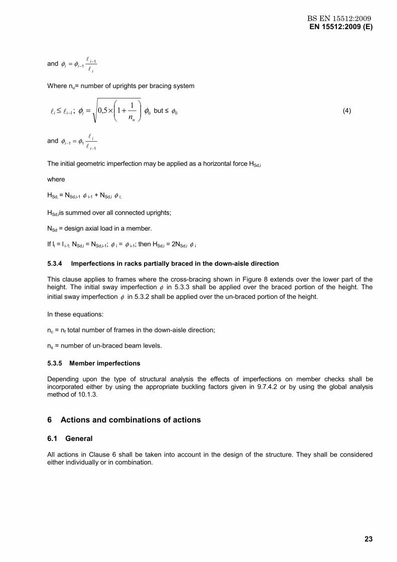
5.3.3.3 Local bracing imperfections
Local bracing imperfections give rise to self equilibrating systems of forces (see Figure 9) which shall be used in the design of the bracing members and their connections only. A first-order analysis may be used.
NSd,i-1
NSd,i
HSd,ii
i-1i-1
ii
Figure 9 — Local bracing imperfections
For uprights without splices φ o = 1/400
For uprights which incorporate splices φ o = 1/200
011 115,0 ; φφ
+×=≥ −−
uiii nll but ≤ 0φ (3)
BS EN 15512:2009EN 15512:2009 (E)
23
and i
iii
l
l 11 −
−= φφ
Where nu= number of uprights per bracing system
01 115,0 ; φφ
+×=≤ −
uiii nll but ≤ 0φ (4)
and 1
11 −
− =i
ii
l
lφφ
The initial geometric imperfection may be applied as a horizontal force HSd,i
where
HSd, = NSd,i-1 φ i-1 + NSd,i φ i;
HSd,iis summed over all connected uprights;
NSd = design axial load in a member.
If li = l i-1; NSd,i = NSd,i-1; φ i = φ i-1; then HSd,i = 2NSd,i φ i
5.3.4 Imperfections in racks partially braced in the down-aisle direction
This clause applies to frames where the cross-bracing shown in Figure 8 extends over the lower part of the height. The initial sway imperfection φ in 5.3.3 shall be applied over the braced portion of the height. The initial sway imperfection φ in 5.3.2 shall be applied over the un-braced portion of the height.
In these equations:
nc = nf total number of frames in the down-aisle direction;
ns = number of un-braced beam levels.
5.3.5 Member imperfections
Depending upon the type of structural analysis the effects of imperfections on member checks shall be incorporated either by using the appropriate buckling factors given in 9.7.4.2 or by using the global analysis method of 10.1.3.
6 Actions and combinations of actions
6.1 General
All actions in Clause 6 shall be taken into account in the design of the structure. They shall be considered either individually or in combination.
BS EN 15512:2009EN 15512:2009 (E)
24
6.2 Permanent actions
6.2.1 General
The permanent actions shall comprise the weight of all construction, including walls, floors, ceilings, stairways and fixed service equipment.
6.2.2 Weights of materials and construction
In estimating dead loads for the purposes of design the actual weights of materials and constructions shall be used. The weight of fixed service equipment, such as sprinklers, electrical feeders, and heating, ventilating, and air conditioning systems, shall be determined and taken into account whenever such equipment is supported by the structural members of the rack.
6.3 Variable actions
6.3.1 General
Where applicable, the design shall take into account actions from the following variable loads.
a) Unit loads.
b) Vertical placement loads.
c) Horizontal placement loads.
d) Rack-guided equipment loads.
e) Floor and walkway loads.
f) Thrusts on handrails.
g) Actions from imperfections (i.e. frame, bracing, member, loading).
h) Impact and accidental loads.
i) Wind loads.
j) Snow loads.
k) Seismic actions.
Variable actions from other equipment connected to the structure shall be determined and taken into account in the design.
6.3.2 Unit loads to be stored
Unit loads shall be determined in accordance with the requirements of EN 15629.
The global analysis and design may be carried out using the specified value of the weight of unit loads and assuming that the rack is uniformly loaded in every bay. This approach may only be used when:
a) The management system in the warehouse can reliably identify unit loads in excess of the specified value and control their distribution within the rack.
b) The specified weight of unit load shall not be less than 80% of the maximum weight of unit load.
BS EN 15512:2009EN 15512:2009 (E)
25
c) All beams are designed to carry the maximum weight of unit load.
d) In upright design the worst case load distribution shall be considered where maximum weight of unit load shall be applied to the upper storage positions up to the specified bay load.
e) The bay load used in the global analysis and design is never exceeded.
If the placement imperfection is not systematic but random the increase of stress and deformation due to loading imperfections at the limit of placement tolerance may be ignored if it does not exceed 12% compared to the beam loaded symmetrically. When the increase is more than 12% the effect on the beam design shall be taken into account as follows:
Where the placement imperfection is not systematic and random placement accuracy is predicted then account of this effect shall be used in the beam design as follows:
Q'Q η= (5)
if 12,1≤ρ 1=η
if 24,112,1 ≤≤ ρ 24,12 −= ρη
if 24,1≥ρ ρη =
where
QQe=ρ
Q = Load on the beam where the pallet is placed in the planned position.
Qe = Load on the beam when the pallet is placed with the maximum misalignment.
6.3.3 Vertical placement loads
The following minimum vertical placement loads shall be applied in applications where unit loads are placed in position.
a) If goods are placed with mechanical equipment.
With single unit load systems (i.e. when there is only one unit load per level per bay), or multiple loads placed simultaneously, load support beams, supporting arms (if any) and beam end connections shall be designed for an additional downward vertical placement load Qpv of 25% of the maximum load placed in the most unfavourable position for the particular determination (moment or shear force).
b) If goods are hand loaded.
Load support beams or supporting arms (if any) and end connections shall be designed for an additional vertical placement load Qpv of 100% of the maximum weight of unit load, placed in the most unfavourable position for the particular determination (moment or shear force).
The downward placement load need not be applied when checking beam deflections or when designing upright frames and other components.
BS EN 15512:2009EN 15512:2009 (E)
26
6.3.4 Horizontal placement loads
6.3.4.1 General
In applications where unit loads are placed in position, the following minimum horizontal placement loads (variable actions) shall be applied in both the cross-aisle and the down-aisle direction at the most unfavourable location. They shall be applied in one direction only, not in both directions simultaneously.
NOTE The minimum horizontal placement load is not intended to represent an impact load arising from misuse of the rack.
An accidental overload shall be taken into consideration (see 6.4) but need not be considered at the same time as the horizontal placement load.
6.3.4.2 Effects of operational methods
The following operational methods shall be used to determine the horizontal placement load.
a) Where goods are placed with manually operated mechanical equipment (e.g. forklift trucks).
1) For racks up to 3 m in height, Qph shall be a load of 0,5 kN applied at any height up to the top of the rack.
2) For racks over 6 m in height, Qph shall be the worst case of either a load of 0,25 kN applied at the top of the rack or a load of 0,5 kN applied at any height up to 3 m.
3) For racks with heights between 3 m and 6 m, Qph shall be the worst case of a load at the top of the rack whose magnitude is determined by linear interpolation between 1) and 2) or a load of 0,5 kN applied at any height up to 3 m.
b) Where goods are placed by automatic storage and retrieval equipment, Qph and its position shall be specified by the materials handling equipment supplier. However, it shall never be less than 0,25 kN.
c) Where backstops are used it shall be clearly defined whether these are safety backstops or buffering backstops and the design load Qph shall be defined by the specifier. For manually operated mechanical equipment this shall be subject to a minimum value of 0,25 Qu in the plane of the upright frame, where Qu is the weight of unit load.
Buffer back stops and pick and deposit stations with positioning devices shall be considered to give rise to variable actions whereas safety backstops shall be considered to give rise to accidental actions. The actions arising from both of these shall be used with the relevant load factors.
NOTE 1 Buffering backstops are considered to be undesirable because they encourage misuse. In some circumstances they are specified for adjustable pallet racking to help the driver with positioning however the forces resulting from these operations are of a high magnitude and are very difficult to quantify precisely.
NOTE 2 Safety backstops might be specified for automated systems (crane racking) to fulfil the requirements of EN 528.
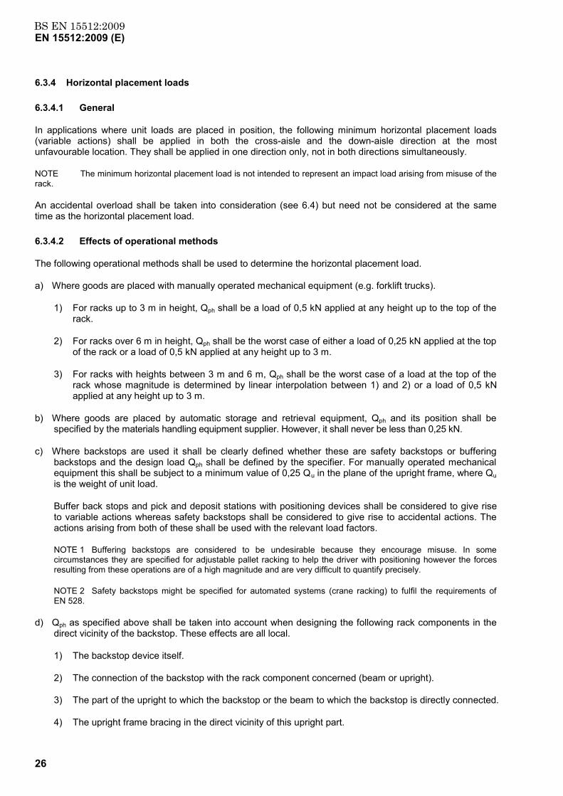
d) Qph as specified above shall be taken into account when designing the following rack components in the direct vicinity of the backstop. These effects are all local.
1) The backstop device itself.
2) The connection of the backstop with the rack component concerned (beam or upright).
3) The part of the upright to which the backstop or the beam to which the backstop is directly connected.
4) The upright frame bracing in the direct vicinity of this upright part.
BS EN 15512:2009EN 15512:2009 (E)
27
Because of damping and spreading effects, a reduced Qph may be considered as:
Qph = 0,1Qu for frame anchoring design assuming based on the upright being unloaded with Qph acting on one frame in the topmost position;
Qph = 0,1Qu for overall frame design (bracing and upright) and Qph acting on one frame on the top most pallet position.
e) If the goods are hand loaded.
Qph = 0,25 kN
6.3.4.3 Application of the horizontal placement load in the down-aisle direction
In the down-aisle direction, the horizontal placement load arises at the beam levels and amplifies the down-aisle sway caused by frame imperfections.
In order to avoid creating unnecessary load cases, the concentrated load Qph may be replaced by a total load of 2Qph distributed uniformly over all beam levels.
6.3.4.4 Application of the horizontal placement load in the cross-aisle direction
In the cross-aisle direction, the most unfavourable location for the placement load shall be either:
a) the top of the upright frame in order to maximise the forces in the bracing system, midway between two bracing nodes of the upright frame lattice in order to maximise the cross-aisle bending moment. In this case, the critical load location is generally in the lowest length of upright between bracing points. If the spacing of bracings is non-uniform, other locations shall also be investigated.
NOTE In order to determine the design bending moments, a global analysis of the complete upright frame need not be carried out. It is sufficient to add positive and negative bending moments of magnitude Qph ℓ/6.
b) The mid-span of a beam in the horizontal plane in order to provide the maximum minor axis bending moment. This case need not be incorporated in the global cross-aisle analysis and a load of 0,5 Qph shall be considered to be carried by a single beam in the horizontal plane through the neutral axis. It is permissible to ignore the interaction with the vertical load causing Qph..
If the installation is designed for loads to be rolled or slid into position, the placement loads Qph generated by the loading process shall be determined and used for in the design.
6.3.5 Effects of rack-guided equipment
In racking operated by rack-guided cranes, the probability of all cranes imposing horizontal loads in the same direction and at the same position in the rack simultaneously decreases as the number of cranes increases, therefore if the upright frames are coupled over the aisles, the total horizontal force Qh,t at guide rail level shall be the value given in Table 1.
BS EN 15512:2009EN 15512:2009 (E)
28
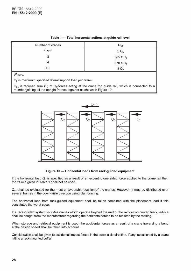
Table 1 — Total horizontal actions at guide rail level
Number of cranes Qh,t
1 or 2
3
4
≥ 5
Σ Qh
0,85 Σ Qh
0,70 Σ Qh
3 Qh
Where:
Qh is maximum specified lateral support load per crane.
Qh,t is reduced sum (Σ) of Qh-forces acting at the crane top guide rail, which is connected to a member joining all the upright frames together as shown in Figure 10.
Qh
Qh,t
Qh Qh Qh
Figure 10 — Horizontal loads from rack-guided equipment
If the horizontal load Qh is specified as a result of an eccentric one sided force applied to the crane rail then the values given in Table 1 shall not be used.
Qh,t shall be evaluated for the most unfavourable position of the cranes. However, it may be distributed over several frames in the down-aisle direction using plan bracing.
The horizontal load from rack-guided equipment shall be taken combined with the placement load if this constitutes the worst case.
If a rack-guided system includes cranes which operate beyond the end of the rack or on curved track, advice shall be sought from the manufacturer regarding the horizontal forces to be resisted by the racking.
When storage and retrieval equipment is used, the accidental forces as a result of a crane traversing a bend at the design speed shall be taken into account.
Consideration shall be given to accidental impact forces in the down-aisle direction, if any, occasioned by a crane hitting a rack-mounted buffer.
BS EN 15512:2009EN 15512:2009 (E)
29
6.3.6 Floor and walkway loads (see also EN 1991-1-1)
The following distributed or concentrated loads, whichever is most critical, shall be used in the design of floors or walkways.
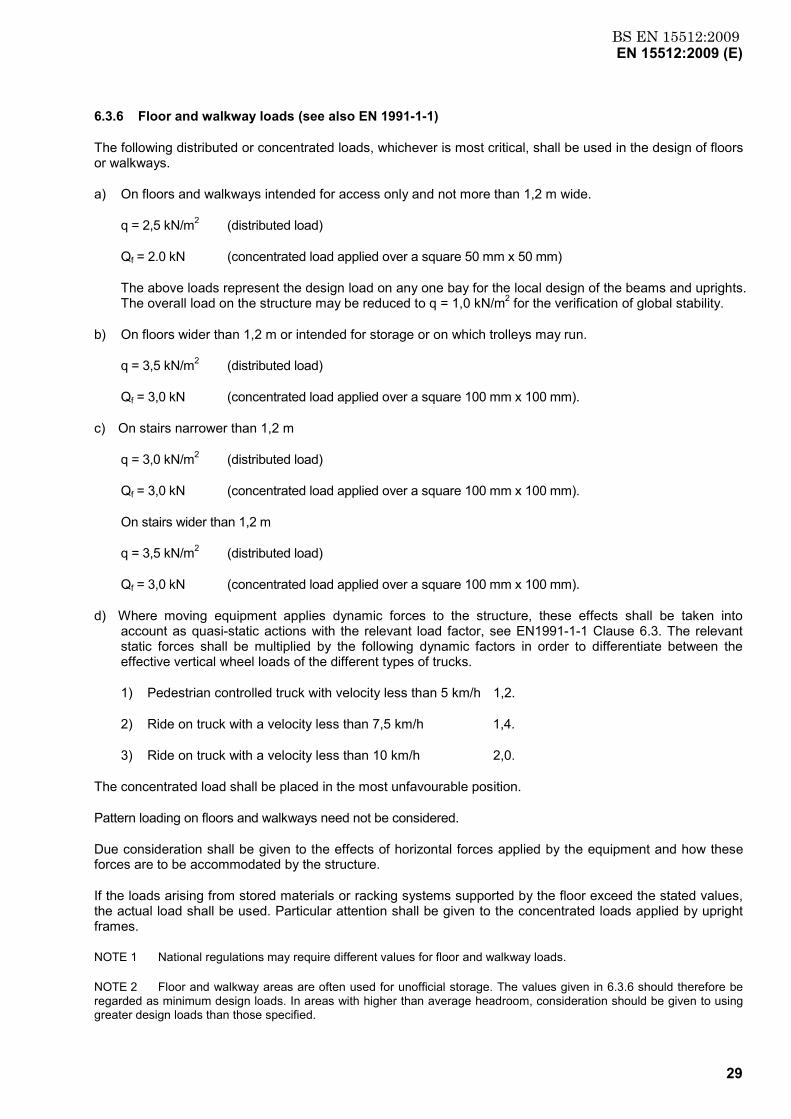
a) On floors and walkways intended for access only and not more than 1,2 m wide.
q = 2,5 kN/m2 (distributed load)
Qf = 2.0 kN (concentrated load applied over a square 50 mm x 50 mm)
The above loads represent the design load on any one bay for the local design of the beams and uprights. The overall load on the structure may be reduced to q = 1,0 kN/m2 for the verification of global stability.
b) On floors wider than 1,2 m or intended for storage or on which trolleys may run.
q = 3,5 kN/m2 (distributed load)
Qf = 3,0 kN (concentrated load applied over a square 100 mm x 100 mm).
c) On stairs narrower than 1,2 m
q = 3,0 kN/m2 (distributed load)
Qf = 3,0 kN (concentrated load applied over a square 100 mm x 100 mm).
On stairs wider than 1,2 m
q = 3,5 kN/m2 (distributed load)
Qf = 3,0 kN (concentrated load applied over a square 100 mm x 100 mm).
d) Where moving equipment applies dynamic forces to the structure, these effects shall be taken into account as quasi-static actions with the relevant load factor, see EN1991-1-1 Clause 6.3. The relevant static forces shall be multiplied by the following dynamic factors in order to differentiate between the effective vertical wheel loads of the different types of trucks.
1) Pedestrian controlled truck with velocity less than 5 km/h 1,2.
2) Ride on truck with a velocity less than 7,5 km/h 1,4.
3) Ride on truck with a velocity less than 10 km/h 2,0.
The concentrated load shall be placed in the most unfavourable position.
Pattern loading on floors and walkways need not be considered.
Due consideration shall be given to the effects of horizontal forces applied by the equipment and how these forces are to be accommodated by the structure.
If the loads arising from stored materials or racking systems supported by the floor exceed the stated values, the actual load shall be used. Particular attention shall be given to the concentrated loads applied by upright frames.
NOTE 1 National regulations may require different values for floor and walkway loads.
NOTE 2 Floor and walkway areas are often used for unofficial storage. The values given in 6.3.6 should therefore be regarded as minimum design loads. In areas with higher than average headroom, consideration should be given to using greater design loads than those specified.
BS EN 15512:2009EN 15512:2009 (E)
30
6.3.7 Actions arising from installation
Where the installation method statement plans for the installers to use safety harnesses suitable anchorage points capable of arresting an accidental fall shall be provided. Residual deformations of the members can occur in the event of a fall.
6.4 Actions due to impact (accidental loads)
6.4.1 General
The live loads and placement loads specified in 6.3 shall be assumed to include adequate allowance for ordinary impact conditions. Provision shall be made in the structural design for uses and loads that involve unusual vibration or dynamic forces.
Impact damage caused by fork-lift trucks or other moving equipment against rack-uprights shall be avoided by appropriate operator training and safety measures. The minimum requirements for the protection of corner uprights shall be as follows.
a) An upright protector with a height of not less than 400 mm shall be positioned at the end upright of each run of racking between cross-aisles.
b) An upright protector shall be positioned at those uprights positioned at all aisle and gangway intersections.
c) The upright protector shall be designed for an energy absorption of at least 400 Nm in any direction at any height between 0,10 m and 0,40 m.
d) The upright protector shall be positioned in such a way that, after its deformation by absorbing an impact, the upright will not be damaged.
e) Rack protection may be designed theoretically; alternatively testing shall be carried out for the purpose of acceptance. Tests shall be on the basis of a mass being dropped or swung into the protector to model the energy absorption requirement of 400 Nm.
NOTE 1 Uprights other than corner uprights may be protected in a direction normal to the aisle at the option of the user.
NOTE 2 The protection of uprights of racking served by mechanically guided handling equipment need not be necessary.
NOTE 3 As an alternative to the use of upright protectors, the installation may be designed to survive the complete removal of a section at the bottom of an upright.
NOTE 4 Accidental actions from fork lift trucks are given in EN 1991-1-7. Such actions need not apply for industrial trucks with the layout, clearances and operation in accordance with EN 15620 and EN 15635.
6.4.2 Accidental vertical actions
Rack components directly above a unit load shall be able to absorb the following accidental vertical force Apv. In general, this force shall be applied at the end of a beam in order to verify that the connector does not disengage. Upward placement loads are accidental variable actions and shall be considered with a load factor γA according to 7.4.
a) if goods are placed with manually operated mechanical equipment (e.g. fork lift trucks)
Apv = 5,0 kN
b) if goods are placed with automatic mechanical equipment: (e.g. stacker cranes, storage and retrieval machines)
BS EN 15512:2009EN 15512:2009 (E)
31
Apv = 0,5 Qu
but Apv ≥ 0,25 kN
and Apv ≤ 5,0 kN
where Qu = weight of unit load.
The requirements for upward placement loads shall be verified by calculation or by testing according to A.2.6.
6.4.3 Accidental horizontal load
An accidental overload in the horizontal direction shall be taken into consideration:
a) If the goods are placed with manually operated but not guided mechanical equipment (e.g. fork lift trucks):
From floor to 0,4 m height on the aisle side upright:
Aph = 2,5 kN in the cross-aisle front to back direction;
Aph = 1,25 kN in the down-aisle direction.
These loads shall be treated as occurring separately. It is permissible to deviate from the requirements of EN 1991-1-7 with regard to fork trucks if the conditions of use justify the deviation. See EN15635.
NOTE The above accidental overload load may be taken by the upright itself or it may require that each upright should be reinforced or protected.
b) If the goods are placed with automatic mechanical equipment (e.g. stacker cranes or storage and retrieval machines) or with manually guided handling equipment (e.g. VNA machines):
Aph = 0,5 kN in either the down-aisle or cross-aisle direction (accidental overload).
NOTE The specified value of Aph may not be acceptable for certain types of equipment and the machinery to be used should be checked and confirmed (i.e. during a malfunction the load may increase until the clutch on the delivery device slips).
6.5 Wind loads
Where required wind loads shall be determined according to the relevant National Regulations.
When a rack is exposed to wind, no account shall be taken of the shielding effects of fully or partially loaded racks upwind of the run in consideration. Each individual row of racking (between adjacent aisles) shall be designed to resist the full wind pressure, suction and wind friction forces.
For a clad rack installation the assembled rows need not be capable of resisting more than the wind force calculated for the complete assembly.
The fully or partially loaded rack shall be considered to be impermeable to wind in the loaded areas unless the effect of permeability can be quantified.
NOTE When determining the limiting deflections for the proper functioning of automatic equipment, a lower value of wind load may be used when specified by the supplier of the equipment.
6.6 Snow loads
Where required snow loads shall be determined according to the relevant National Regulations.
BS EN 15512:2009EN 15512:2009 (E)
32
6.7 Seismic actions
Where required, seismic actions shall be determined according to the relevant National Regulations.
7 Partial factors and combination rules
7.1 General
Weight of unit loads and global rack imperfections shall together constitute a single action. Placement loads shall constitute a separate action.
Global imperfections and placement loads shall be combined in one direction at a time. The combination of imperfections or placement loads in one direction with imperfections or placement loads in the other orthogonal direction need not be considered.
7.2 Combinations of actions for the ultimate limit state
The design values of actions shall be combined using the following rules, whichever gives the larger value:
considering only the most unfavourable variable action;
Q + G k,1QkG γγ∑ (6)
considering all unfavourable variable actions which can occur simultaneously;
Q 1i
0,9 + G i ,k QkG γγ≥∑
∑ (7)
design for accidental load.
A + Q + G kAik,QA1i
kGA γγγ ∑∑≥
(8)
where
Gk = characteristic value of permanent action (dead load);
Qk,1 = characteristic value of one of the variable loads;
Qk,I = characteristic value of a typical variable load;
Ak = characteristic value of an accidental load;
γ G = partial factor for permanent loads;
γ Q = partial factor for variable loads;
γ A = partial factor for accidental loads.
7.3 Combination of actions for serviceability limit states
The design values of actions shall be combined using the combination factors ψ0, as given in EN 1990. For pallet racking the simplified combination rules given in Equations (5), (6) and (7) may be used, whichever gives the larger value:
BS EN 15512:2009EN 15512:2009 (E)
33
considering only the most unfavourable variable action;
Q + G k,1QkG γγ∑ (9)
considering all unfavourable variable actions;
Q 1i 0,9 + G ik,QkG ≥∑
∑ γγ (10)
where the notation is defined in 7.2.
Placement loads need not be considered at the serviceability limit state.
NOTE 1 The weight of the unit loads vary up to a maximum which is used in design. The specifier should define a design value for the weight of the unit load (or different design values of the weight of the unit load for the upright frame and/or down aisle global design), which will not be exceeded, see EN 15629. This can result in the specification of design weights which are conservative, thus justifying the 0,9 combination factor for load combinations.
NOTE 2 Unless unusual conditions prevail, it is usual that the goods to be stored plus the global imperfections constitute the action with the largest effect.
7.4 Load factors
The load factors γ f are given in Table 2.
NOTE National regulations may require different load factors.
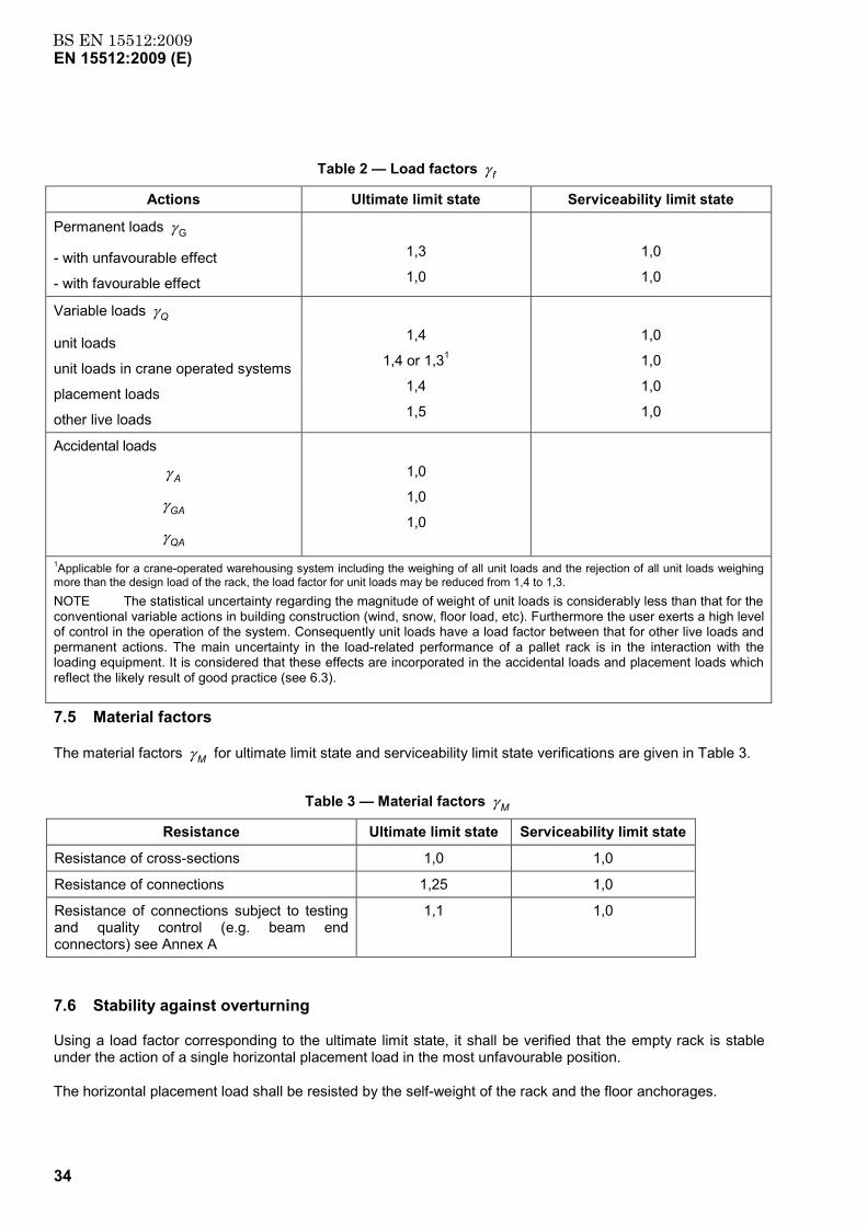
BS EN 15512:2009EN 15512:2009 (E)
34
Table 2 — Load factors γ f
Actions Ultimate limit state Serviceability limit state
Permanent loads γ G
- with unfavourable effect
- with favourable effect
1,3
1,0
1,0
1,0
Variable loads γ Q
unit loads
unit loads in crane operated systems
placement loads
other live loads
1,4
1,4 or 1,31
1,4
1,5
1,0
1,0
1,0
1,0
Accidental loads
γ A
γ GA
γ QA
1,0
1,0
1,0
1Applicable for a crane-operated warehousing system including the weighing of all unit loads and the rejection of all unit loads weighing more than the design load of the rack, the load factor for unit loads may be reduced from 1,4 to 1,3. NOTE The statistical uncertainty regarding the magnitude of weight of unit loads is considerably less than that for the conventional variable actions in building construction (wind, snow, floor load, etc). Furthermore the user exerts a high level of control in the operation of the system. Consequently unit loads have a load factor between that for other live loads and permanent actions. The main uncertainty in the load-related performance of a pallet rack is in the interaction with the loading equipment. It is considered that these effects are incorporated in the accidental loads and placement loads which reflect the likely result of good practice (see 6.3).
7.5 Material factors
The material factors γ M for ultimate limit state and serviceability limit state verifications are given in Table 3.
Table 3 — Material factors γ M
Resistance Ultimate limit state Serviceability limit state
Resistance of cross-sections 1,0 1,0
Resistance of connections 1,25 1,0
Resistance of connections subject to testing and quality control (e.g. beam end connectors) see Annex A
1,1 1,0
7.6 Stability against overturning
Using a load factor corresponding to the ultimate limit state, it shall be verified that the empty rack is stable under the action of a single horizontal placement load in the most unfavourable position.
The horizontal placement load shall be resisted by the self-weight of the rack and the floor anchorages.
BS EN 15512:2009EN 15512:2009 (E)
35
In every upright frame the base plates shall be fixed squarely to the uprights and secured to the floor through any shimming material or grouting necessary to ensure that the uprights are solidly supported under the whole area of the base plate. The shimming material shall be steel and shall be prevented from shifting relative to the base plate.
7.7 Racks braced against the building structure
If the racks are braced against the building structure, the two structures can impose forces upon each other. These forces shall be calculated and the owner of the building or his representative shall be informed of these forces and their location.
8 Steel
8.1 General
8.1.1 Preliminary considerations
The nominal values of material properties given in this section should be adopted as characteristic values in design calculations for the manufacture of racking products. Steels shall be suitable for cold-forming, welding and galvanising where appropriate.
Specified steels according to Table 3.1 of EN 1993-1-1:2005, and 3.1a and 3.1b of EN 1993-1-3:2006, the properties and chemical composition of which are in compliance with the relevant standards, fulfil the requirements of this section.
Other steels may be used provided that:
a) their properties and chemical composition are at least equivalent to steels, for which the standards are listed in Table 3.1 of EN 1993-1-1:2005 and 3.1 of EN 1993-1-3:2006,
b) if the steel is for cold-forming, it fulfils the requirements of the bend test A.1.2. and the ratio of the characteristic ultimate tensile strength to the characteristic yield strength satisfies fu/fy ≥ 1,05 where fy, fu = characteristic tensile yield strength and tensile ultimate strength of the basic material.
NOTE 1 The minimum ratio in 8.1.1 differs from that specified in EN 1993-1-1 but is acceptable for racking products.
NOTE 2 See Annex D relating to research into the use of materials with a close ratio between fu and fy
8.1.2 Material properties
The nominal values of the yield strength fy and the ultimate strength fu for structural steel shall be obtained by
a) adopting the values fy = Reh and fu = Rm direct from the relevant product standard,
b) using the simplification given in 8.1.5,
c) using the testing regime specified in 8.1.4.
8.1.3 Design values of material coefficients (general mechanical properties)
The following properties of steel shall be assumed in design.
a) Modulus of Elasticity E = 210 000 N/mm2.
b) Shear Modulus G = E/[2(1+υ )] N/mm2.
BS EN 15512:2009EN 15512:2009 (E)
36
c) Poisson’s Ratio υ = 0,3.
d) Coefficient of linear thermal expansion α = 12 x 10-6 per 0C.
e) Density ρ = 7850 kg/m3.
8.1.4 Steels with no guaranteed mechanical properties
8.1.4.1 General
For steels in this category a series of tensile tests may be used to justify the values to be used or a lower bound value of yield strength may be used.
8.1.4.2 Additional tests on steel
The mechanical properties of basic materials shall be measured from tensile tests according to section A.1.1. The results of tensile tests shall be subject to statistical control, see 13.3.3.
When conducting the following procedures for coils:
a) testing to determine the minimum guaranteed mechanical properties for the steel used in production;
b) to justify the use in design of a yield stress higher than the guaranteed value;
c) to demonstrate adequate ductility.
The minimum frequency of testing shall be one test from each original coil (after slitting and cold-reducing, if cold-reducing is part of the process). Samples shall be taken lengthwise from the middle of the width near the end of the coil.
The results of the mechanical tests shall be statistically analysed in accordance with 13.3.3, in order to derive characteristic values of the yield or ultimate tensile strength of the material for design purposes. Where at least 100 test results have been accumulated over a long period, those in excess of 100 which are more than 12 months old shall be discarded from the analysis (see Annex A)
For sheets and sections, the mechanical properties given in 8.1.5 for unspecified steels shall be used.
8.1.5 Untested steels
The following values of fyb shall be assumed if the steel grade is not specified or if the basic material is not available for testing:
Hot rolled sections 200 N/mm2;
Other steels 140 N/mm2.
8.2 Average yield strength of sections
Where required, the average yield strength (fya) shall be determined for members as defined in EN 1993-1-3.
8.3 Special selection of production material
When a coil of material is specially selected for a particular application, excluding testing material, and the design strength to be used is in excess of the nominal design strength for that material, the maximum value of the design strength shall not exceed 90% of the value given on the test report for the coil.
BS EN 15512:2009EN 15512:2009 (E)
37
8.4 Fracture toughness
Brittle fracture of material below 6 mm in thickness need not be considered for temperatures down to -35°C for non hot-dipped steel sheet in accordance with this specification.
For untested steels covered by 8.1.5 the 6 mm thickness limit given above shall be reduced to 2 mm.
NOTE Further guidance on this subject can be found in EN 1993-1-10
8.5 Dimensional tolerances
8.5.1 General
Tolerance limits of sections and members shall be in accordance with EN 10162.
The dimensional and mass tolerances of rolled steel sections, structural hollow sections and plates shall conform to the relevant product standard unless more severe tolerances are specified.
For structural analysis and design the nominal values of dimensions shall be used.
8.5.2 Thickness of material
The design rules given in this document shall be limited to the following core thickness tc exclusive of coatings unless specified otherwise, where:
0,5 ≤ tc ≤ 8,0 mm
The use of thinner steel is not precluded but the load bearing capacity shall be determined by appropriate tests. If components with thicker steels are used they shall be designed in accordance with EN 1993-1-1. Design expressions for base plates (see 9.9) may be used with a material thickness greater than 8 mm.
8.5.3 Tolerances on thickness
The design rules given for cold-formed members have been developed on the basis of thickness tolerances of half the tolerances specified as normal in EN 10326:2004. When larger tolerances are used, the nominal values of thickness shall be adjusted to maintain the equivalent reliability (see EN 1993-1-3).
For continuously hot-dip metal coated material with a nominal thickness ≤ 1,5 mm supplied with the restricted special tolerances given in EN 10143, the design thickness t shall be taken as equal to the nominal core thickness tc.
In the case of continuously hot-dip metal coated steel sheet and strip conforming to EN 10147, the core thickness tc shall be as given in EN 1993-1-3.
NOTE The thickness of the zinc protection is usually a total of 0,04 mm for 275 g/m2.
8.5.4 Width and depth of a cold-formed section
The width and depth of plane elements of a section shall fulfil the requirements in Table 4 and 5.
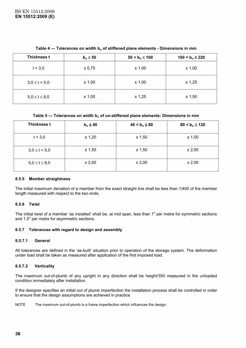
BS EN 15512:2009EN 15512:2009 (E)
38
Table 4 — Tolerances on width bo of stiffened plane elements - Dimensions in mm
Thickness t bo ≤≤ 50 50 < bo ≤≤ 100 100 < bo ≤≤≤≤ 220
t < 3,0 ± 0,75 ± 1,00 ± 1,00
3,0 ≤ t < 5,0 ± 1,00 ± 1,00 ± 1,25
5,0 ≤ t ≤ 8,0 ± 1,00 ± 1,25 ± 1,50
Table 5 — Tolerances on width bo of un-stiffened plane elements: Dimensions in mm
Thickness t bo ≤≤≤≤ 40 40 < bo ≤≤≤≤ 80 80 < bo ≤≤ 120
t < 3,0 ± 1,20 ± 1,50 ± 1,50
3,0 ≤ t < 5,0 ± 1,50 ± 1,50 ± 2,00
5,0 ≤ t ≤ 8,0 ± 2,00 ± 2,00 ± 2,00
8.5.5 Member straightness
The initial maximum deviation of a member from the exact straight line shall be less than 1/400 of the member length measured with respect to the two ends.
8.5.6 Twist
The initial twist of a member ‘as installed’ shall be, at mid span, less than 1o per metre for symmetric sections and 1,5o per metre for asymmetric sections.
8.5.7 Tolerances with regard to design and assembly
8.5.7.1 General
All tolerances are defined in the ‘as-built’ situation prior to operation of the storage system. The deformation under load shall be taken as measured after application of the first imposed load.
8.5.7.2 Verticality
The maximum out-of-plumb of any upright in any direction shall be height/350 measured in the unloaded condition immediately after installation.
If the designer specifies an initial out of plumb imperfection the installation process shall be controlled in order to ensure that the design assumptions are achieved in practice.
NOTE The maximum out-of-plumb is a frame imperfection which influences the design.
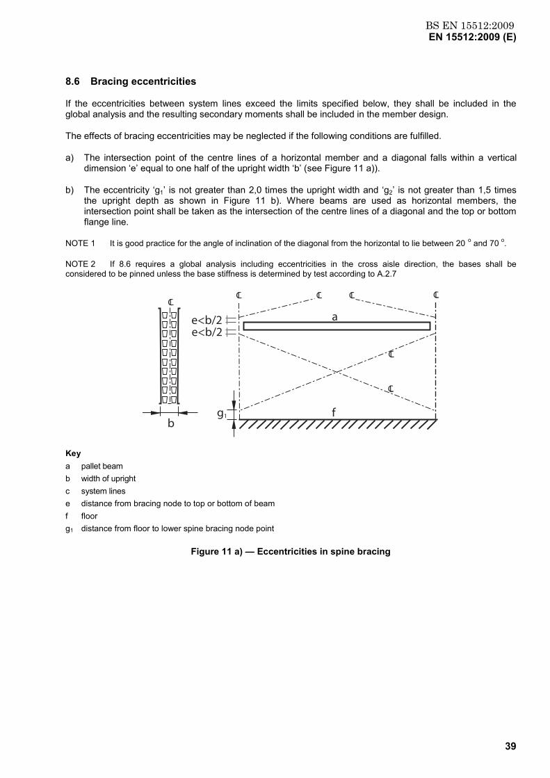
BS EN 15512:2009EN 15512:2009 (E)
39
8.6 Bracing eccentricities
If the eccentricities between system lines exceed the limits specified below, they shall be included in the global analysis and the resulting secondary moments shall be included in the member design.
The effects of bracing eccentricities may be neglected if the following conditions are fulfilled.
a) The intersection point of the centre lines of a horizontal member and a diagonal falls within a vertical dimension ‘e’ equal to one half of the upright width ‘b’ (see Figure 11 a)).
b) The eccentricity ‘g1’ is not greater than 2,0 times the upright width and ‘g2’ is not greater than 1,5 times the upright depth as shown in Figure 11 b). Where beams are used as horizontal members, the intersection point shall be taken as the intersection of the centre lines of a diagonal and the top or bottom flange line.
NOTE 1 It is good practice for the angle of inclination of the diagonal from the horizontal to lie between 20 o and 70 o.
NOTE 2 If 8.6 requires a global analysis including eccentricities in the cross aisle direction, the bases shall be considered to be pinned unless the base stiffness is determined by test according to A.2.7
CL
CL
CL CL CL CL
g1
e<b/2e<b/2
CL
bf
a
Key a pallet beam b width of upright c system lines e distance from bracing node to top or bottom of beam f floor g1 distance from floor to lower spine bracing node point
Figure 11 a) — Eccentricities in spine bracing
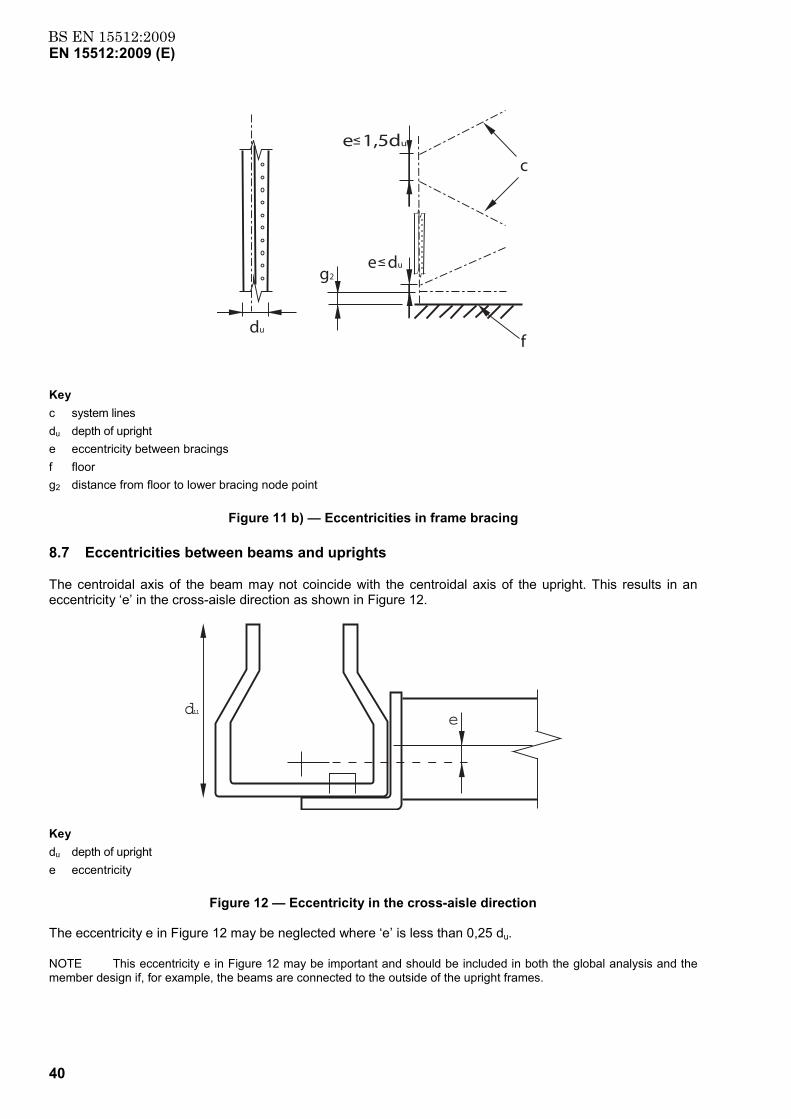
BS EN 15512:2009EN 15512:2009 (E)
40
du
g2e du
e 1,5du
c
f
Key c system lines du depth of upright e eccentricity between bracings f floor g2 distance from floor to lower bracing node point
Figure 11 b) — Eccentricities in frame bracing
8.7 Eccentricities between beams and uprights
The centroidal axis of the beam may not coincide with the centroidal axis of the upright. This results in an eccentricity ‘e’ in the cross-aisle direction as shown in Figure 12.
due
Key du depth of upright e eccentricity
Figure 12 — Eccentricity in the cross-aisle direction
The eccentricity e in Figure 12 may be neglected where ‘e’ is less than 0,25 du.
NOTE This eccentricity e in Figure 12 may be important and should be included in both the global analysis and the member design if, for example, the beams are connected to the outside of the upright frames.
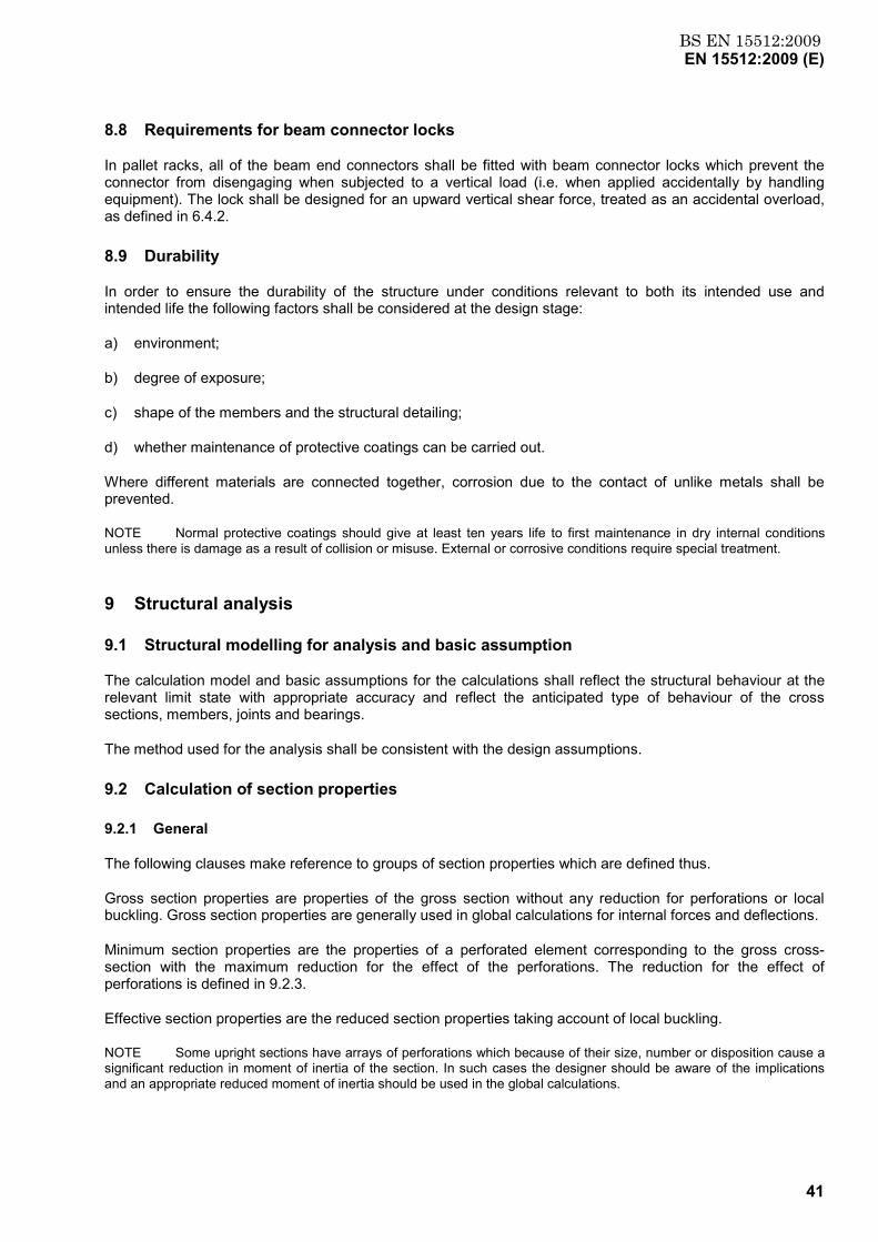
BS EN 15512:2009EN 15512:2009 (E)
41
8.8 Requirements for beam connector locks
In pallet racks, all of the beam end connectors shall be fitted with beam connector locks which prevent the connector from disengaging when subjected to a vertical load (i.e. when applied accidentally by handling equipment). The lock shall be designed for an upward vertical shear force, treated as an accidental overload, as defined in 6.4.2.
8.9 Durability
In order to ensure the durability of the structure under conditions relevant to both its intended use and intended life the following factors shall be considered at the design stage:
a) environment;
b) degree of exposure;
c) shape of the members and the structural detailing;
d) whether maintenance of protective coatings can be carried out.
Where different materials are connected together, corrosion due to the contact of unlike metals shall be prevented.
NOTE Normal protective coatings should give at least ten years life to first maintenance in dry internal conditions unless there is damage as a result of collision or misuse. External or corrosive conditions require special treatment.
9 Structural analysis
9.1 Structural modelling for analysis and basic assumption
The calculation model and basic assumptions for the calculations shall reflect the structural behaviour at the relevant limit state with appropriate accuracy and reflect the anticipated type of behaviour of the cross sections, members, joints and bearings.
The method used for the analysis shall be consistent with the design assumptions.
9.2 Calculation of section properties
9.2.1 General
The following clauses make reference to groups of section properties which are defined thus.
Gross section properties are properties of the gross section without any reduction for perforations or local buckling. Gross section properties are generally used in global calculations for internal forces and deflections.
Minimum section properties are the properties of a perforated element corresponding to the gross cross-section with the maximum reduction for the effect of the perforations. The reduction for the effect of perforations is defined in 9.2.3.
Effective section properties are the reduced section properties taking account of local buckling.
NOTE Some upright sections have arrays of perforations which because of their size, number or disposition cause a significant reduction in moment of inertia of the section. In such cases the designer should be aware of the implications and an appropriate reduced moment of inertia should be used in the global calculations.
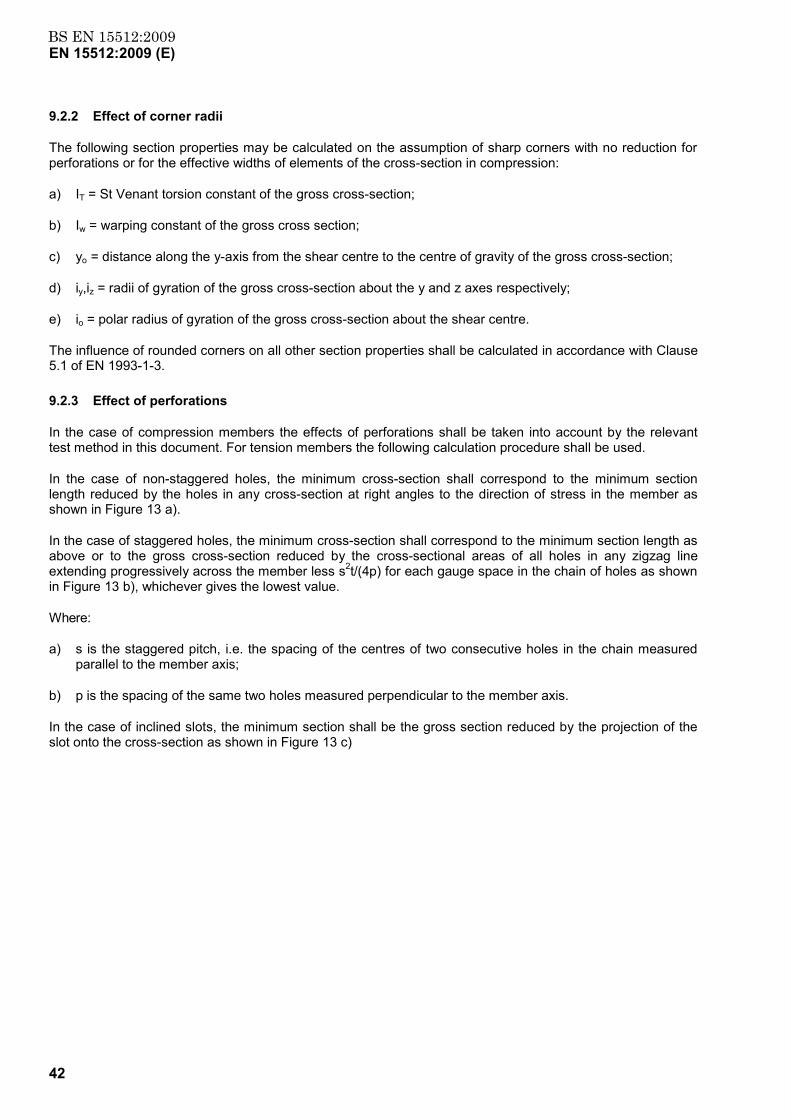
BS EN 15512:2009EN 15512:2009 (E)
42
9.2.2 Effect of corner radii
The following section properties may be calculated on the assumption of sharp corners with no reduction for perforations or for the effective widths of elements of the cross-section in compression:
a) IT = St Venant torsion constant of the gross cross-section;
b) Iw = warping constant of the gross cross section;
c) yo = distance along the y-axis from the shear centre to the centre of gravity of the gross cross-section;
d) iy,iz = radii of gyration of the gross cross-section about the y and z axes respectively;
e) io = polar radius of gyration of the gross cross-section about the shear centre.
The influence of rounded corners on all other section properties shall be calculated in accordance with Clause 5.1 of EN 1993-1-3.
9.2.3 Effect of perforations
In the case of compression members the effects of perforations shall be taken into account by the relevant test method in this document. For tension members the following calculation procedure shall be used.
In the case of non-staggered holes, the minimum cross-section shall correspond to the minimum section length reduced by the holes in any cross-section at right angles to the direction of stress in the member as shown in Figure 13 a).
In the case of staggered holes, the minimum cross-section shall correspond to the minimum section length as above or to the gross cross-section reduced by the cross-sectional areas of all holes in any zigzag line extending progressively across the member less s2t/(4p) for each gauge space in the chain of holes as shown in Figure 13 b), whichever gives the lowest value.
Where:
a) s is the staggered pitch, i.e. the spacing of the centres of two consecutive holes in the chain measured parallel to the member axis;
b) p is the spacing of the same two holes measured perpendicular to the member axis.
In the case of inclined slots, the minimum section shall be the gross section reduced by the projection of the slot onto the cross-section as shown in Figure 13 c)
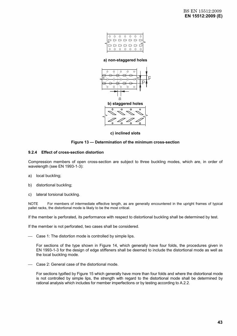
BS EN 15512:2009EN 15512:2009 (E)
43
a) non-staggered holes
pp
s b) staggered holes
c) inclined slots
Figure 13 — Determination of the minimum cross-section
9.2.4 Effect of cross-section distortion
Compression members of open cross-section are subject to three buckling modes, which are, in order of wavelength (see EN 1993-1-3):
a) local buckling;
b) distortional buckling;
c) lateral torsional buckling.
NOTE For members of intermediate effective length, as are generally encountered in the upright frames of typical pallet racks, the distortional mode is likely to be the most critical.
If the member is perforated, its performance with respect to distortional buckling shall be determined by test.
If the member is not perforated, two cases shall be considered.
Case 1: The distortion mode is controlled by simple lips.
For sections of the type shown in Figure 14, which generally have four folds, the procedures given in EN 1993-1-3 for the design of edge stiffeners shall be deemed to include the distortional mode as well as the local buckling mode.
Case 2: General case of the distortional mode.
For sections typified by Figure 15 which generally have more than four folds and where the distortional mode is not controlled by simple lips, the strength with regard to the distortional mode shall be determined by rational analysis which includes for member imperfections or by testing according to A.2.2.
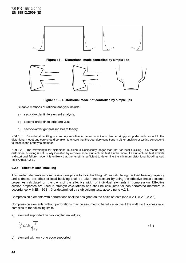
BS EN 15512:2009EN 15512:2009 (E)
44
Figure 14 — Distortional mode controlled by simple lips
Figure 15 — Distortional mode not controlled by simple lips
Suitable methods of rational analysis include:
a) second-order finite element analysis;
b) second-order finite strip analysis;
c) second-order generalised beam theory.
NOTE 1 Distortional buckling is extremely sensitive to the end conditions (fixed or simply supported with respect to the distortional mode) and care should be taken to ensure that the boundary conditions in either analysis or testing correspond to those in the prototype member.
NOTE 2 The wavelength for distortional buckling is significantly longer than that for local buckling. This means that distortional buckling is not usually identified by a conventional stub-column test. Furthermore, if a stub-column test exhibits a distortional failure mode, it is unlikely that the length is sufficient to determine the minimum distortional buckling load (see Annex A.2.2).
9.2.5 Effect of local buckling
Thin walled elements in compression are prone to local buckling. When calculating the load bearing capacity and stiffness, the effect of local buckling shall be taken into account by using the effective cross-sectional properties calculated on the basis of the effective width of individual elements in compression. Effective section properties are used in strength calculations and shall be calculated for non-perforated members in accordance with EN 1993-1-3 or determined by stub column tests according to A.2.1.
Compression elements with perforations shall be designed on the basis of tests (see A.2.1, A.2.2, A.2.3).
Compression elements without perforations may be assumed to be fully effective if the width to thickness ratio complies to the following limits:
a) element supported on two longitudinal edges;
fE 281
tb
y
p ,≤ (11)
b) element with only one edge supported;
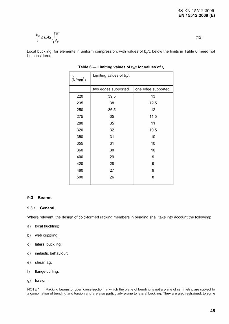
BS EN 15512:2009EN 15512:2009 (E)
45
fE42 0
tb
y
p ,≤ (12)
Local buckling, for elements in uniform compression, with values of bp/t, below the limits in Table 6, need not be considered.
Table 6 — Limiting values of bp/t for values of fy
9.3 Beams
9.3.1 General
Where relevant, the design of cold-formed racking members in bending shall take into account the following:
a) local buckling;
b) web crippling;
c) lateral buckling;
d) inelastic behaviour;
e) shear lag;
f) flange curling;
g) torsion.
NOTE 1 Racking beams of open cross-section, in which the plane of bending is not a plane of symmetry, are subject to a combination of bending and torsion and are also particularly prone to lateral buckling. They are also restrained, to some
fy (N/mm2)
Limiting values of bp/t
two edges supported one edge supported
220
235
250
275
280
320
350
355
360
400
420
460
500
39.5
38
36.5
35
35
32
31
31
30
29
28
27
26
13
12,5
12
11,5
11
10,5
10
10
10
9
9
9
8
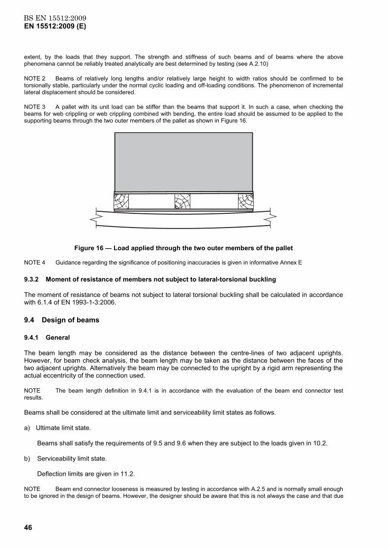
BS EN 15512:2009EN 15512:2009 (E)
46
extent, by the loads that they support. The strength and stiffness of such beams and of beams where the above phenomena cannot be reliably treated analytically are best determined by testing (see A.2.10)
NOTE 2 Beams of relatively long lengths and/or relatively large height to width ratios should be confirmed to be torsionally stable, particularly under the normal cyclic loading and off-loading conditions. The phenomenon of incremental lateral displacement should be considered.
NOTE 3 A pallet with its unit load can be stiffer than the beams that support it. In such a case, when checking the beams for web crippling or web crippling combined with bending, the entire load should be assumed to be applied to the supporting beams through the two outer members of the pallet as shown in Figure 16.
Figure 16 — Load applied through the two outer members of the pallet
NOTE 4 Guidance regarding the significance of positioning inaccuracies is given in informative Annex E
9.3.2 Moment of resistance of members not subject to lateral-torsional buckling
The moment of resistance of beams not subject to lateral torsional buckling shall be calculated in accordance with 6.1.4 of EN 1993-1-3:2006.
9.4 Design of beams
9.4.1 General
The beam length may be considered as the distance between the centre-lines of two adjacent uprights. However, for beam check analysis, the beam length may be taken as the distance between the faces of the two adjacent uprights. Alternatively the beam may be connected to the upright by a rigid arm representing the actual eccentricity of the connection used.
NOTE The beam length definition in 9.4.1 is in accordance with the evaluation of the beam end connector test results.
Beams shall be considered at the ultimate limit and serviceability limit states as follows.
a) Ultimate limit state.
Beams shall satisfy the requirements of 9.5 and 9.6 when they are subject to the loads given in 10.2.
b) Serviceability limit state.
Deflection limits are given in 11.2.
NOTE Beam end connector looseness is measured by testing in accordance with A.2.5 and is normally small enough to be ignored in the design of beams. However, the designer should be aware that this is not always the case and that due
BS EN 15512:2009EN 15512:2009 (E)
47
provision should be made for excessive looseness that can otherwise lead to unacceptable deflections at the service load and to additional bending in the beam.
9.4.2 Loads on beams
It is usual to consider the loading on the beams to be uniformly distributed unless specified otherwise. In racks braced against side-sway, the coefficients given in Annex F may be used to convert the actual loading arrangement into an equivalent uniformly distributed load.
NOTE 1 The mid-span bending moment and the central deflection are not affected by sway effects.
NOTE 2 The designer should identify special cases of stored materials which may impose additional loads on the beams. For example, tyres or barrels may impose horizontal load as well as vertical load.
NOTE 3 Attention should be paid to point loads from pallet bearers which can cause web crippling. A pallet with its unit load may be stiffer than the beams that support it. In such a case, when checking the beams for web crippling or web crippling combined with bending, the entire load may be assumed to be applied to the supporting beams through the two outer members of the pallet.
Where beams carry axial loads as part of a bracing system, the beams shall be checked according to 9.4.6.
9.4.3 Design bending moments for beams
9.4.3.1 General
If the restraining effect of the beam end connector is taken into account, then the design moments may be taken directly from the results of a second-order analysis at the design load factor.
NOTE In frames which are braced against sway, a first-order analysis can provide a satisfactory estimate of the bending moment in the beam in the ultimate load condition.
In frames which sway, the design bending moments at the centre of the beam may be obtained from a first-order analysis.
Plastic design of the beams may be used, even if global stability is justified on the basis of elastic design, provided that proper consideration is given to the rotation capacity of the beam end connector.
9.4.3.2 Redistribution of bending moments in the case of elastic analysis
If an elastic analysis with linear connector behaviour shows that the ultimate moment of resistance of one or both beam end connections is exceeded, the bending moment may be redistributed in the beam and the associated beam end by up to 15% of the end moment, as shown in Figure 17, provided that:
a) the bending moment at mid-span is also redistributed in order to maintain static equilibrium;
b) after redistribution, the bending moments at the ends of the beam do not exceed the ultimate moment of resistance of either the beam or the beam end connector. See 9.5 and 9.6.
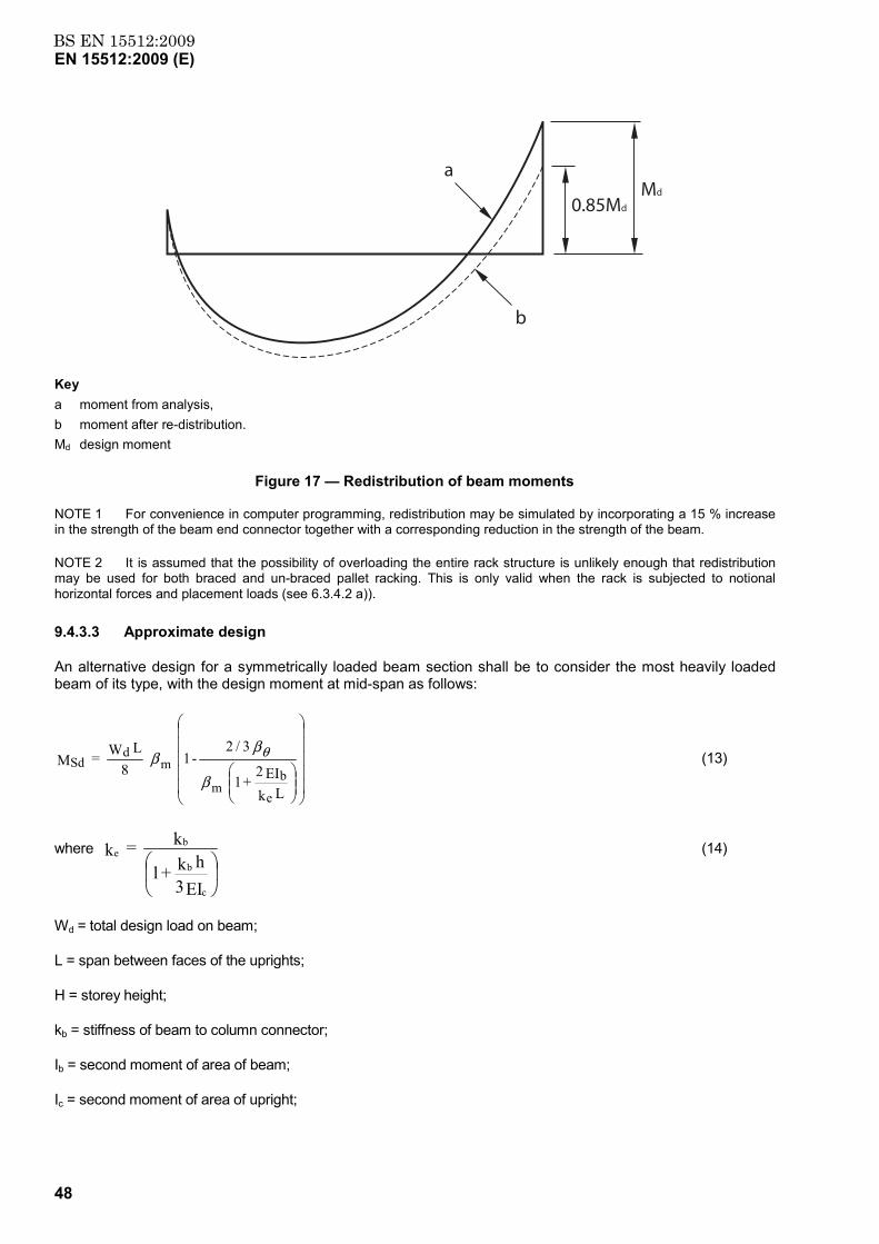
BS EN 15512:2009EN 15512:2009 (E)
48
a
b
0.85Md
Md
Key a moment from analysis, b moment after re-distribution. Md design moment
Figure 17 — Redistribution of beam moments
NOTE 1 For convenience in computer programming, redistribution may be simulated by incorporating a 15 % increase in the strength of the beam end connector together with a corresponding reduction in the strength of the beam.
NOTE 2 It is assumed that the possibility of overloading the entire rack structure is unlikely enough that redistribution may be used for both braced and un-braced pallet racking. This is only valid when the rack is subjected to notional horizontal forces and placement loads (see 6.3.4.2 a)).
9.4.3.3 Approximate design
An alternative design for a symmetrically loaded beam section shall be to consider the most heavily loaded beam of its type, with the design moment at mid-span as follows:
L k
EI2 + 1
3/2 - 1
8L W = M
e
bm
md
Sdβ
ββ θ (13)
where
EI3h k + l
k = k
c
b
be (14)
Wd = total design load on beam;
L = span between faces of the uprights;
H = storey height;
kb = stiffness of beam to column connector;
Ib = second moment of area of beam;
Ic = second moment of area of upright;
BS EN 15512:2009EN 15512:2009 (E)
49
where βθ and βm are according to Annex G.
9.4.4 Design shear force for beams
In racks which are braced against sway, the design shear force for the beam and beam end connector shall be obtained from either a first-order or second-order global analysis.
In racks which are free to sway, the design shear force shall be obtained from a second-order analysis.
If a first-order analysis is used, the shear forces in the beam due to sway shall be amplified by the factor
V - VV =
Sdcr
crβ (15)
where
VSd = the design value of the vertical load on the frame,
Vcr = the elastic critical value of the vertical load for failure in a sway mode.
The design shear force is the aggregate of the amplified sway shear force and that due to the vertical loads on the rack.
In racks of regular construction and loading, when the bases are pinned, the design shear force may be taken as:
βφ
L4
1) - n(3h W2 +
2W = S sdd
Sd (16)
In racks of regular construction and loading, when the bases are semi-rigid, the design shear force may be taken as:
βφ
L4
1) - n(2h W2 +
2W = S sdd
Sd (17)
where
φ = sway imperfection
ns = number of beam levels
9.4.5 Deflection of beams
In the serviceability limit state the maximum deflection of any beam shall be obtained from either a first- or second-order analysis which takes due account of pattern loading.
For racks of regular construction and loading, the maximum deflection of a beam may be taken as:
∆
∆
∆
L kEI2 + 1
0.8 - 1
EI384L W5 =
ebb
3sermax
β
ββ θ (18)
where
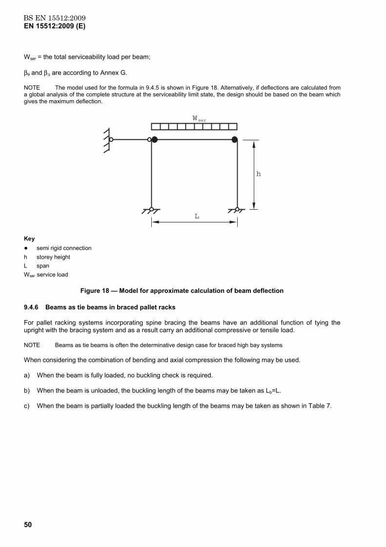
BS EN 15512:2009EN 15512:2009 (E)
50
Wser = the total serviceability load per beam;
βθ and β∆ are according to Annex G.
NOTE The model used for the formula in 9.4.5 is shown in Figure 18. Alternatively, if deflections are calculated from a global analysis of the complete structure at the serviceability limit state, the design should be based on the beam which gives the maximum deflection.
Wser
L
h
Key ● semi rigid connection h storey height L span Wser service load
Figure 18 — Model for approximate calculation of beam deflection
9.4.6 Beams as tie beams in braced pallet racks
For pallet racking systems incorporating spine bracing the beams have an additional function of tying the upright with the bracing system and as a result carry an additional compressive or tensile load.
NOTE Beams as tie beams is often the determinative design case for braced high bay systems
When considering the combination of bending and axial compression the following may be used.
a) When the beam is fully loaded, no buckling check is required.
b) When the beam is unloaded, the buckling length of the beams may be taken as Lb=L.
c) When the beam is partially loaded the buckling length of the beams may be taken as shown in Table 7.
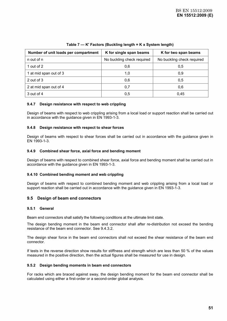
BS EN 15512:2009EN 15512:2009 (E)
51
Table 7 — K' Factors (Buckling length = K x System length)
Number of unit loads per compartment K for single span beams K for two span beams
n out of n No buckling check required No buckling check required
1 out of 2 0,6 0,5
1 at mid span out of 3 1,0 0,9
2 out of 3 0,6 0,5
2 at mid span out of 4 0,7 0,6
3 out of 4 0,5 0,45
9.4.7 Design resistance with respect to web crippling
Design of beams with respect to web crippling arising from a local load or support reaction shall be carried out in accordance with the guidance given in EN 1993-1-3.
9.4.8 Design resistance with respect to shear forces
Design of beams with respect to shear forces shall be carried out in accordance with the guidance given in EN 1993-1-3.
9.4.9 Combined shear force, axial force and bending moment
Design of beams with respect to combined shear force, axial force and bending moment shall be carried out in accordance with the guidance given in EN 1993-1-3.
9.4.10 Combined bending moment and web crippling
Design of beams with respect to combined bending moment and web crippling arising from a local load or support reaction shall be carried out in accordance with the guidance given in EN 1993-1-3.
9.5 Design of beam end connectors
9.5.1 General
Beam end connectors shall satisfy the following conditions at the ultimate limit state.
The design bending moment in the beam end connector shall after re-distribution not exceed the bending resistance of the beam end connector. See 9.4.3.2.
The design shear force in the beam end connectors shall not exceed the shear resistance of the beam end connector.
If tests in the reverse direction show results for stiffness and strength which are less than 50 % of the values measured in the positive direction, then the actual figures shall be measured for use in design.
9.5.2 Design bending moments in beam end connectors
For racks which are braced against sway, the design bending moment for the beam end connector shall be calculated using either a first-order or a second-order global analysis.
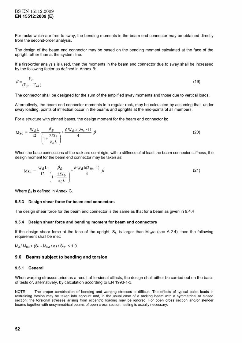
BS EN 15512:2009EN 15512:2009 (E)
52
For racks which are free to sway, the bending moments in the beam end connector may be obtained directly from the second-order analysis.
The design of the beam end connector may be based on the bending moment calculated at the face of the upright rather than at the system line.
If a first-order analysis is used, then the moments in the beam end connector due to sway shall be increased by the following factor as defined in Annex B:
)( sdcr
crVV
V−
=β (19)
The connector shall be designed for the sum of the amplified sway moments and those due to vertical loads.
Alternatively, the beam end connector moments in a regular rack, may be calculated by assuming that, under sway loading, points of inflection occur in the beams and uprights at the mid-points of all members.
For a structure with pinned bases, the design moment for the beam end connector is:
βφβθ
41) - (3h W +
2+ 1
12
L W = M ddSd
s
bb
n
LkEI
(20)
When the base connections of the rack are semi-rigid, with a stiffness of at least the beam connector stiffness, the design moment for the beam end connector may be taken as:
βφβθ
41) - nh(2 W +
2
+ 1
12L W = M sdd
Sd
Lk
EI
bb
(21)
Where βθ is defined in Annex G.
9.5.3 Design shear force for beam end connectors
The design shear force for the beam end connector is the same as that for a beam as given in 9.4.4
9.5.4 Design shear force and bending moment for beam end connectors
If the design shear force at the face of the upright, Sd, is larger than MRd/a (see A.2.4), then the following requirement shall be met:
Md / MRd + (Sd - MRd / a) / SRd ≤ 1.0
9.6 Beams subject to bending and torsion
9.6.1 General
When warping stresses arise as a result of torsional effects, the design shall either be carried out on the basis of tests or, alternatively, by calculation according to EN 1993-1-3.
NOTE The proper combination of bending and warping stresses is difficult. The effects of typical pallet loads in restraining torsion may be taken into account and, in the usual case of a racking beam with a symmetrical or closed section; the torsional stresses arising from eccentric loading may be ignored. For open cross section and/or slender beams together with unsymmetrical beams of open cross-section, testing is usually necessary.
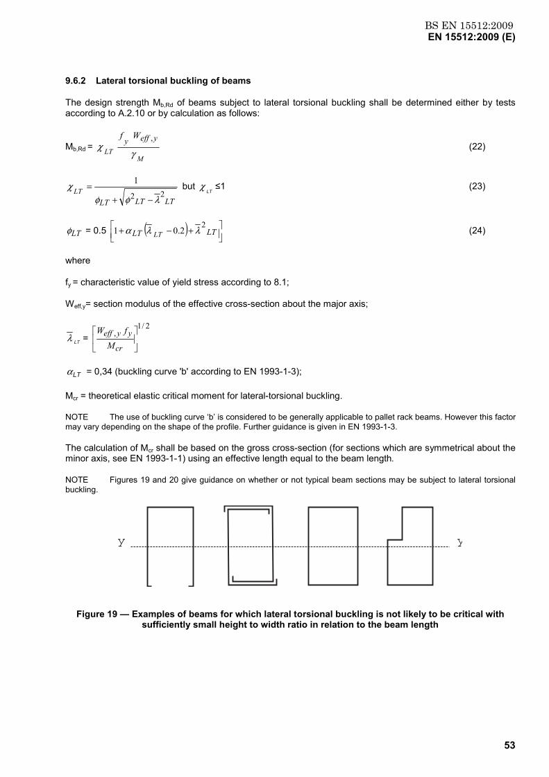
BS EN 15512:2009EN 15512:2009 (E)
53
9.6.2 Lateral torsional buckling of beams
The design strength Mb,Rd of beams subject to lateral torsional buckling shall be determined either by tests according to A.2.10 or by calculation as follows:
Mb,Rd = M
LT
yeffy Wf
γχ
, (22)
LTLTLTLT 22
1
λφφχ
−+= but
LTχ ≤1 (23)
LTφ = 0.5 ( )
+−+ LTLT LT
22.01 λλα (24)
where
fy = characteristic value of yield stress according to 8.1;
Weff,y= section modulus of the effective cross-section about the major axis;
LTλ = 2/1
,
cr
yyeffM
fW
LTα = 0,34 (buckling curve 'b' according to EN 1993-1-3);
Mcr = theoretical elastic critical moment for lateral-torsional buckling.
NOTE The use of buckling curve ‘b’ is considered to be generally applicable to pallet rack beams. However this factor may vary depending on the shape of the profile. Further guidance is given in EN 1993-1-3.
The calculation of Mcr shall be based on the gross cross-section (for sections which are symmetrical about the minor axis, see EN 1993-1-1) using an effective length equal to the beam length.
NOTE Figures 19 and 20 give guidance on whether or not typical beam sections may be subject to lateral torsional buckling.
y y
Figure 19 — Examples of beams for which lateral torsional buckling is not likely to be critical with sufficiently small height to width ratio in relation to the beam length
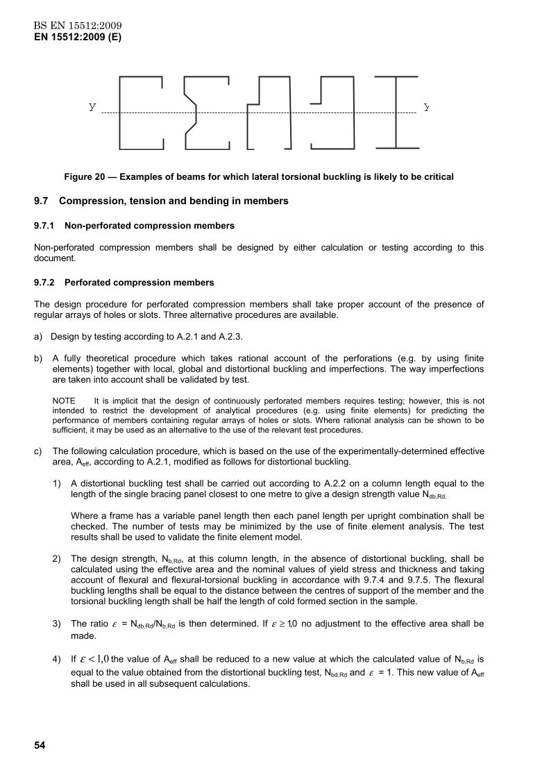
BS EN 15512:2009EN 15512:2009 (E)
54
yy
Figure 20 — Examples of beams for which lateral torsional buckling is likely to be critical
9.7 Compression, tension and bending in members
9.7.1 Non-perforated compression members
Non-perforated compression members shall be designed by either calculation or testing according to this document.
9.7.2 Perforated compression members
The design procedure for perforated compression members shall take proper account of the presence of regular arrays of holes or slots. Three alternative procedures are available.
a) Design by testing according to A.2.1 and A.2.3.
b) A fully theoretical procedure which takes rational account of the perforations (e.g. by using finite elements) together with local, global and distortional buckling and imperfections. The way imperfections are taken into account shall be validated by test.
NOTE It is implicit that the design of continuously perforated members requires testing; however, this is not intended to restrict the development of analytical procedures (e.g. using finite elements) for predicting the performance of members containing regular arrays of holes or slots. Where rational analysis can be shown to be sufficient, it may be used as an alternative to the use of the relevant test procedures.
c) The following calculation procedure, which is based on the use of the experimentally-determined effective area, Aeff, according to A.2.1, modified as follows for distortional buckling.
1) A distortional buckling test shall be carried out according to A.2.2 on a column length equal to the length of the single bracing panel closest to one metre to give a design strength value Ndb,Rd.
Where a frame has a variable panel length then each panel length per upright combination shall be checked. The number of tests may be minimized by the use of finite element analysis. The test results shall be used to validate the finite element model.
2) The design strength, Nb,Rd, at this column length, in the absence of distortional buckling, shall be calculated using the effective area and the nominal values of yield stress and thickness and taking account of flexural and flexural-torsional buckling in accordance with 9.7.4 and 9.7.5. The flexural buckling lengths shall be equal to the distance between the centres of support of the member and the torsional buckling length shall be half the length of cold formed section in the sample.
3) The ratio ε = Ndb.Rd/Nb,Rd is then determined. If 0,1≥ε no adjustment to the effective area shall be made.
4) If 0,1<ε the value of Aeff shall be reduced to a new value at which the calculated value of Nb,Rd is equal to the value obtained from the distortional buckling test, Nbd,Rd and ε = 1. This new value of Aeff shall be used in all subsequent calculations.
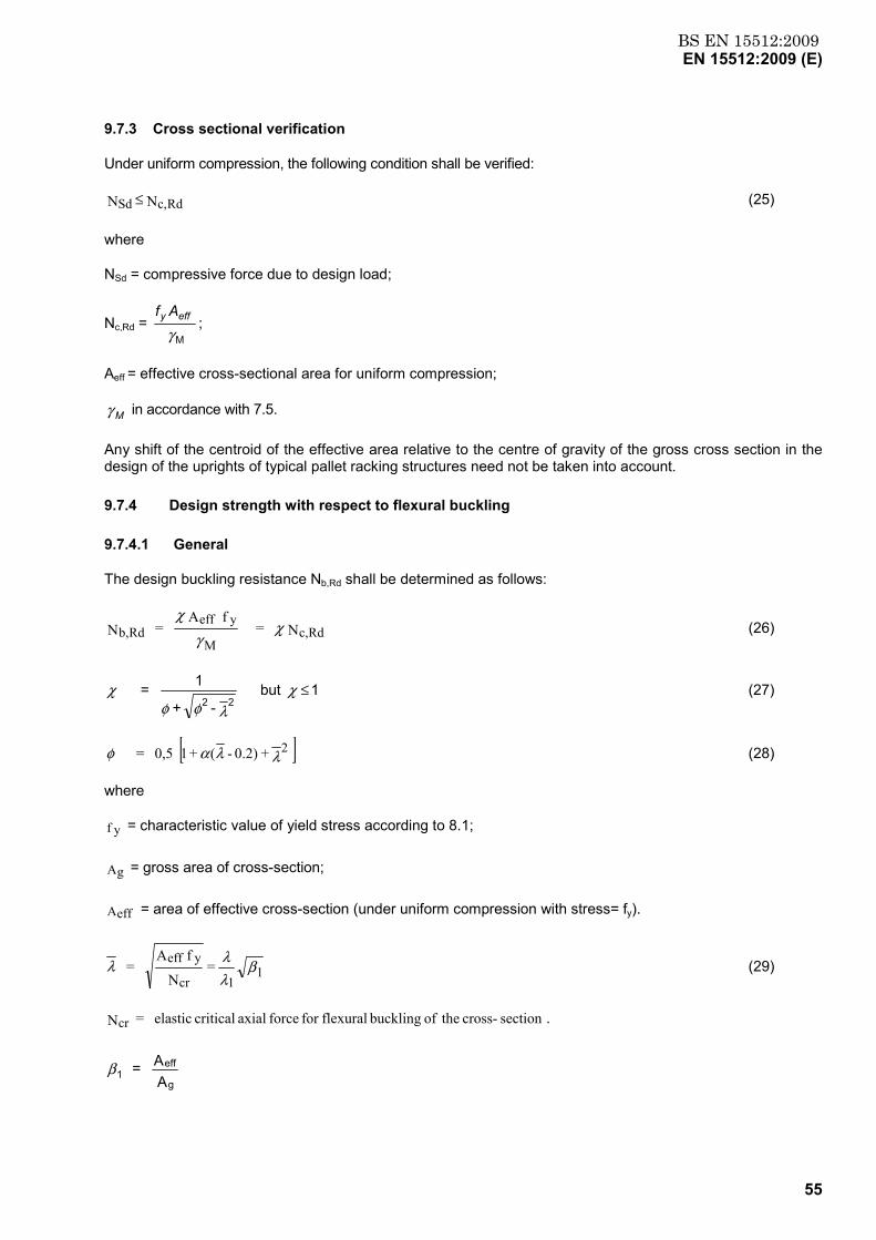
BS EN 15512:2009EN 15512:2009 (E)
55
9.7.3 Cross sectional verification
Under uniform compression, the following condition shall be verified:
N N Rdc,Sd ≤ (25)
where
NSd = compressive force due to design load;
Nc,Rd = M γeffy Af
;
Aeff = effective cross-sectional area for uniform compression;
γ M in accordance with 7.5.
Any shift of the centroid of the effective area relative to the centre of gravity of the gross cross section in the design of the uprights of typical pallet racking structures need not be taken into account.
9.7.4 Design strength with respect to flexural buckling
9.7.4.1 General
The design buckling resistance Nb,Rd shall be determined as follows:
N = f A
= N Rdc,M
yeffRdb, χ
γχ
(26)
- +
1 = 22
λφφχ but 1 ≤χ (27)
[ ] + 0.2) - ( + 1 0,5 = 2λλαφ (28)
where
f y = characteristic value of yield stress according to 8.1;
Ag = gross area of cross-section;
Aeff = area of effective cross-section (under uniform compression with stress= fy).
βλλλ 11cr
yeff = N
f A = (29)
sectioncross- theof buckling flexuralfor force axial critical elastic = Ncr .
AA =
g
eff1β
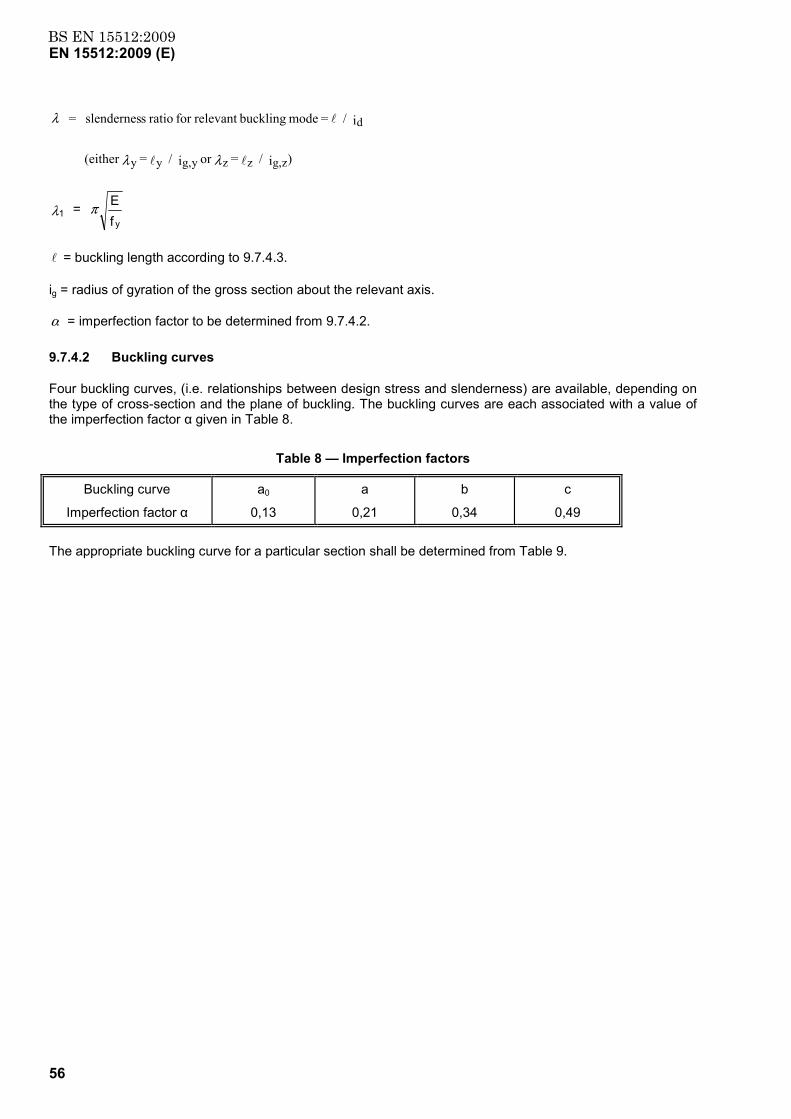
BS EN 15512:2009EN 15512:2009 (E)
56
)i / = or i / = (either
i / = mode bucklingrelevant for ratio sslendernes =
zg,zzyg,yy
d
ll
l
λλ
λ
fE = y
1 πλ
l = buckling length according to 9.7.4.3.
ig = radius of gyration of the gross section about the relevant axis.
α = imperfection factor to be determined from 9.7.4.2.
9.7.4.2 Buckling curves
Four buckling curves, (i.e. relationships between design stress and slenderness) are available, depending on the type of cross-section and the plane of buckling. The buckling curves are each associated with a value of the imperfection factor α given in Table 8.
Table 8 — Imperfection factors
Buckling curve
Imperfection factor α
a0
0,13
a
0,21
b
0,34
c
0,49
The appropriate buckling curve for a particular section shall be determined from Table 9.
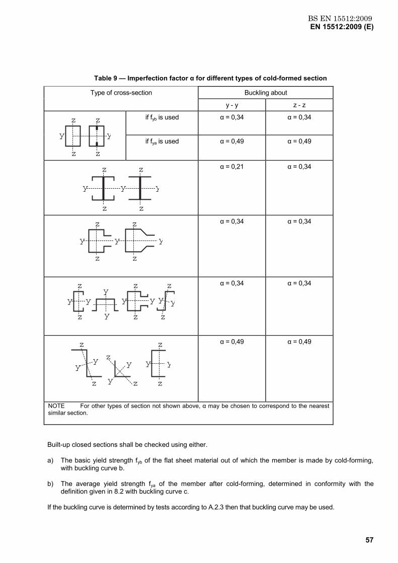
BS EN 15512:2009EN 15512:2009 (E)
57
Table 9 — Imperfection factor α for different types of cold-formed section
Type of cross-section Buckling about
y - y z - z
y
z z
z z
y
if fyb is used
α = 0,34 α = 0,34
if fya is used α = 0,49 α = 0,49
y y y
z z
z z
α = 0,21 α = 0,34
y y y
z
z z
z
α = 0,34
α = 0,34
z
z
y y
y
y
z
z
y y y y
z
z
α = 0,34
α = 0,34
z
z
yy
z
z
y
y y y
z
z
α = 0,49
α = 0,49
NOTE For other types of section not shown above, α may be chosen to correspond to the nearest similar section.
Built-up closed sections shall be checked using either.
a) The basic yield strength fyb of the flat sheet material out of which the member is made by cold-forming, with buckling curve b.
b) The average yield strength fya of the member after cold-forming, determined in conformity with the definition given in 8.2 with buckling curve c.
If the buckling curve is determined by tests according to A.2.3 then that buckling curve may be used.
BS EN 15512:2009EN 15512:2009 (E)
58
9.7.4.3 Buckling length
The buckling length l for a given member which is an element of a system shall be determined as the length of a column of the same cross-section and with both ends pinned which has the same Euler critical load as the system under consideration.
If the axial forces and bending moment in the plane of buckling of a member have been determined on the basis of a second-order analysis, they are already enhanced by second-order effects and the buckling length may be considered as equal to the system length. When second-order global analysis is used, it is permissible to use in-plane buckling lengths for the non-sway mode for member design.
A suitable procedure shall be to determine the non-sway elastic critical load of the rack and then, for each storey in turn, to calculate the effective length for use with the appropriate column curve.
NOTE 1 The determination of the buckling length which follows is applicable to the members of braced frames and frames for which no second-order analysis is available.
NOTE 2 The buckling length l of a member in compression may be determined by either rational analysis or testing giving due regard to the behaviour of the complete frame and the nature of the restraints provided at connections of bracing members or other restraining elements.
NOTE 3 In general, the system lengths, together with the resulting flexural and torsional buckling lengths, in the down aisle and cross aisle direction will not be the same. There is also the possibility of splices and changes of cross section between the bracing nodes. In the cross aisle direction, additional problems are created by changes of axial load between the bracing nodes. Prescriptive guidance cannot be given regarding compression member design which includes all of the possibilities. If an advanced three dimensional analysis is used according to 10.1.3, this problem does not arise. In other cases the design is based on two independent orthogonal analyses and the designer may therefore need to use judgement in determining appropriate effective lengths for member design. In general, in a braced frame, or in an un-braced frame in which the member forces have been determined on the basis of second order analysis, these should not exceed the relevant system length.
If the buckling length has not been determined by global analysis, the following values of the effective length factor K shall be used, where.
l = KL
where L = system length (i.e. length between bracing points relevant to the buckling mode under consideration)
a) For any member with both ends held in position with regard to the buckling mode under consideration.
K = 1.
b) For the bottom length of an upright in a braced upright frame in the cross-aisle direction.
Provided that:
1) bracing members are connected to both flanges of the upright;
2) bracing eccentricities satisfy the requirements of 8.6 and 8.7;
3) a base plate is fitted to the upright;
4) the floor is concrete.
K = 0,9
If the above conditions except 3) or 4) are satisfied;
BS EN 15512:2009EN 15512:2009 (E)
59
K = 1,0.
L= height from floor to second node point (h in Figure 21 a) and b)).
NOTE In a braced frame, if the bottom node is not near the floor (see 8.6), the length between the floor and the first node should be considered as being free to sway.
c) For all other parts of the upright in a braced upright frame in the cross-aisle direction.
K = 1,0
L = height between node points (hp in Figure 21 a) and b)).
NOTE The situation shown in Figure 21 c) arises frequently and special care should be taken with the stability of the un-braced upper portion of the uprights.
d) For horizontal and diagonal bracing members in an upright frame.
Provided the bracing member is welded with a fillet weld of length at least 20 mm to both flanges of the uprights.
K = 0,9 only for in plane buckling
For all other cases, K = 1,0
If the connections at the ends of a bracing member do not coincide with its system lines, i.e. the eccentricities do not comply with 8.6, the member shall be designed for combined axial load and bending.
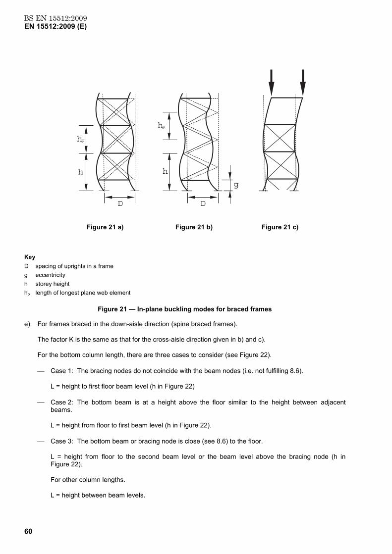
BS EN 15512:2009EN 15512:2009 (E)
60
h
D
h
g
D
hp
hp
Figure 21 a) Figure 21 b) Figure 21 c)
Key D spacing of uprights in a frame g eccentricity h storey height hp length of longest plane web element
Figure 21 — In-plane buckling modes for braced frames
e) For frames braced in the down-aisle direction (spine braced frames).
The factor K is the same as that for the cross-aisle direction given in b) and c).
For the bottom column length, there are three cases to consider (see Figure 22).
Case 1: The bracing nodes do not coincide with the beam nodes (i.e. not fulfilling 8.6).
L = height to first floor beam level (h in Figure 22)
Case 2: The bottom beam is at a height above the floor similar to the height between adjacent beams.
L = height from floor to first beam level (h in Figure 22).
Case 3: The bottom beam or bracing node is close (see 8.6) to the floor.
L = height from floor to the second beam level or the beam level above the bracing node (h in Figure 22).
For other column lengths.
L = height between beam levels.
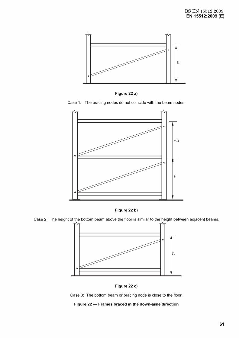
BS EN 15512:2009EN 15512:2009 (E)
61
h
Figure 22 a)
Case 1: The bracing nodes do not coincide with the beam nodes.
h
h
Figure 22 b)
Case 2: The height of the bottom beam above the floor is similar to the height between adjacent beams.
h
Figure 22 c)
Case 3: The bottom beam or bracing node is close to the floor.
Figure 22 — Frames braced in the down-aisle direction
BS EN 15512:2009EN 15512:2009 (E)
62
In a braced frame in the down aisle direction, if the bottom node is not in accordance with 8.6 the length between the floor and the first node shall be considered as being free to sway.
f) For frames un-braced in the down-aisle direction.
When a second-order analysis is carried out overall stability is taken into account in the enhanced bending moments and it is therefore conservative to design using K = 1 with values of L given in e) above.
9.7.5 Torsional and flexural-torsional buckling
9.7.5.1 General
Torsional buckling is usually only critical for point-symmetric open sections. Mono-symmetric and non-symmetric sections are generally subject to flexural-torsional buckling.
In addition to checking for flexural-torsional buckling, flexural buckling about the weaker principal axis should also be checked.
9.7.5.2 Design strength with respect to torsional and flexural-torsional buckling
The design buckling resistance Nb,Rd corresponding to torsional or flexural-torsional buckling shall be determined by using the expressions given in 9.7.4 by substituting the lesser of Ncr,T or Ncr,FT for Ncr, with:
L
I E + IG i1 = N 2
eT
w2T2Tcr,
o
π critical force for torsional buckling (30)
+−
NN
)4( )NN
1( - NN
+ 12β
N = N
ycr,
Tcr,22
ycr,
Tcr,
ycr,
Tcr,ycr,FTcr,
oo
iy (31)
NOTE Expression (31) applies only for cross-sections that are symmetrical about the y-y axis (e.g. zo = 0). For other sections, guidance should be obtained from literature.
2
o
oiy
-1 β with
= (32)
where
Ncr,FT = critical force for flexural-torsional buckling;
Ncr,y is the is the elastic critical load of the upright based on buckling lengths according to 9.7.4.3.
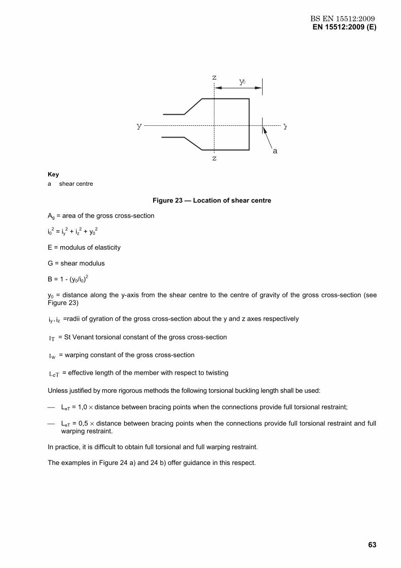
BS EN 15512:2009EN 15512:2009 (E)
63
yy
z
za
y0
Key a shear centre
Figure 23 — Location of shear centre
Ag = area of the gross cross-section
i02 = iy2 + iz2 + y02
E = modulus of elasticity
G = shear modulus
Β = 1 - (y0/i0)2
y0 = distance along the y-axis from the shear centre to the centre of gravity of the gross cross-section (see Figure 23)
i ,i zy =radii of gyration of the gross cross-section about the y and z axes respectively
IT = St Venant torsional constant of the gross cross-section
Iw = warping constant of the gross cross-section
LeT = effective length of the member with respect to twisting
Unless justified by more rigorous methods the following torsional buckling length shall be used:
LeT = 1,0 × distance between bracing points when the connections provide full torsional restraint;
LeT = 0,5 × distance between bracing points when the connections provide full torsional restraint and full warping restraint.
In practice, it is difficult to obtain full torsional and full warping restraint.
The examples in Figure 24 a) and 24 b) offer guidance in this respect.
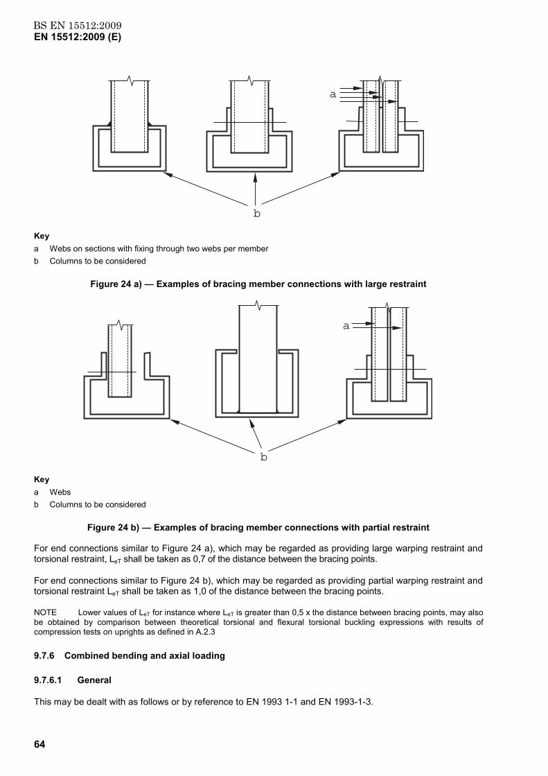
BS EN 15512:2009EN 15512:2009 (E)
64
b
a
Key a Webs on sections with fixing through two webs per member b Columns to be considered
Figure 24 a) — Examples of bracing member connections with large restraint
b
a
Key a Webs b Columns to be considered
Figure 24 b) — Examples of bracing member connections with partial restraint
For end connections similar to Figure 24 a), which may be regarded as providing large warping restraint and torsional restraint, LeT shall be taken as 0,7 of the distance between the bracing points.
For end connections similar to Figure 24 b), which may be regarded as providing partial warping restraint and torsional restraint LeT shall be taken as 1,0 of the distance between the bracing points.
NOTE Lower values of LeT for instance where LeT is greater than 0,5 x the distance between bracing points, may also be obtained by comparison between theoretical torsional and flexural torsional buckling expressions with results of compression tests on uprights as defined in A.2.3
9.7.6 Combined bending and axial loading
9.7.6.1 General
This may be dealt with as follows or by reference to EN 1993 1-1 and EN 1993-1-3.
BS EN 15512:2009EN 15512:2009 (E)
65
9.7.6.2 Bending and axial compression
For members in combined compression and bending, the following condition shall be satisfied:
1 MM
+ M
M +
NN
RDz,c,
Sdz,
Rdy,c,
Sdy,
Rdc,
Sd ≤ (33)
where:
NSd, MSd are due to the design loads and Nc,Rd and Mc,Rd are according to 9.3 and 9.7.3.
9.7.6.3 Bending and axial compression without lateral-torsional buckling
In addition to satisfying 9.7.6.2 members subject to combined bending and axial compression shall also satisfy
1 / f W
M k + / f W
M k +
/ f A N
Myzeff,
Sdz,z
Myyeff,
Sdy,y
Myeffmin
Sd ≤γγγχ
(34)
Where:
1,5 kbut f A
N - 1 = k y
yeffy
Sdyy ≤
χ
µ
0,90 but 4) - (2 = yyM,yy ≤µβλµ
1,5 kbut f A
N - 1 = k z
yeffz
Sdzz ≤
χµ
0,9 but 4) - (2 = zzM,zz ≤µβλµ
minχ = the lesser of dbχ , yχ and zχ , where dbχ is the reduction factor calculated in 9.7.2.c and yχ and zχ are the reduction factors from 9.7.4 for the y- y and z- z axes respectively. The influence of any distortional buckling effects should be taken into account.
yeffmincritRddb, fANN χ== may be determined as the characteristic value of resistance obtained from compression test on upright sections according to A.2.3 or by calculation based on stub column tests provided that distortional buckling effects are taken into account in accordance with 9.7.2
βM,y and βM,z are equivalent uniform moment factors for flexural buckling, (see 9.7.6.4).
If the stress resultants arise as a result of a second-order analysis with global imperfections, ky and/or kz is not greater than 1.
If the stress resultants arise as a result of a second-order analysis with global and local imperfections, yχ and/or zχ = 1, as appropriate, provided that there is no effect due to distortional buckling.
Weff,y is the effective section modulus of the cross-section when subject only to moment about the y-y axis
Weff,z is the effective section modulus of the cross-section when subject only to moment about the z-z axis
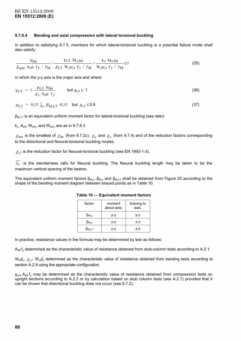
BS EN 15512:2009EN 15512:2009 (E)
66
9.7.6.4 Bending and axial compression with lateral torsional buckling
In addition to satisfying 9.7.5, members for which lateral-torsional buckling is a potential failure mode shall also satisfy:
1 / f W
M k +
/ f W M k
+ / f A
N
Myzeff,
Sdz,z
Myyeff,LT
Sdy,LT
Myeffmin
Sd ≤γγχγχ
(35)
in which the y-y axis is the major axis and where
f A
N - 1 = k
yeffz
SdLTLT χ
µbut kLT ≤ 1 (36)
0,15 - 0,15 = LTM,zLT βλµ but 0.9 LT ≤µ (37)
βM.LT is an equivalent uniform moment factor for lateral-torsional buckling (see later)
kz, Aeff, Weff.y and Weff.z are as in 9.7.6.3
minχ is the smallest of dbχ (from 9.7.2c). yχ and zχ (from 9.7.4) and of the reduction factors corresponding to the distortional and flexural-torsional buckling modes.
LTχ is the reduction factor for flexural-torsional buckling (see EN 1993-1-3).
zλ is the slenderness ratio for flexural buckling. The flexural buckling length may be taken to be the maximum vertical spacing of the beams.
The equivalent uniform moment factors βM,y, βM,z and βM,LT shall be obtained from Figure 25 according to the shape of the bending moment diagram between braced points as in Table 10.
Table 10 — Equivalent moment factors
factor: moment about axis:
bracing to axis:
βM,y y-y y-y
βM,z z-z z-z
βM,LT y-y z-z
In practice, resistance values in the formula may be determined by test as follows:
Aeff fy determined as the characteristic value of resistance obtained from stub-column tests according to A.2.1.
Wefffy, LTχ Wefffy determined as the characteristic value of resistance obtained from bending tests according to section A.2.9 using the appropriate configuration.
χmin Aeff fy may be determined as the characteristic value of resistance obtained from compression tests on upright sections according to A.2.3 or by calculation based on stub column tests (see A.2.1) provided that it can be shown that distortional buckling does not occur (see 9.7.2).
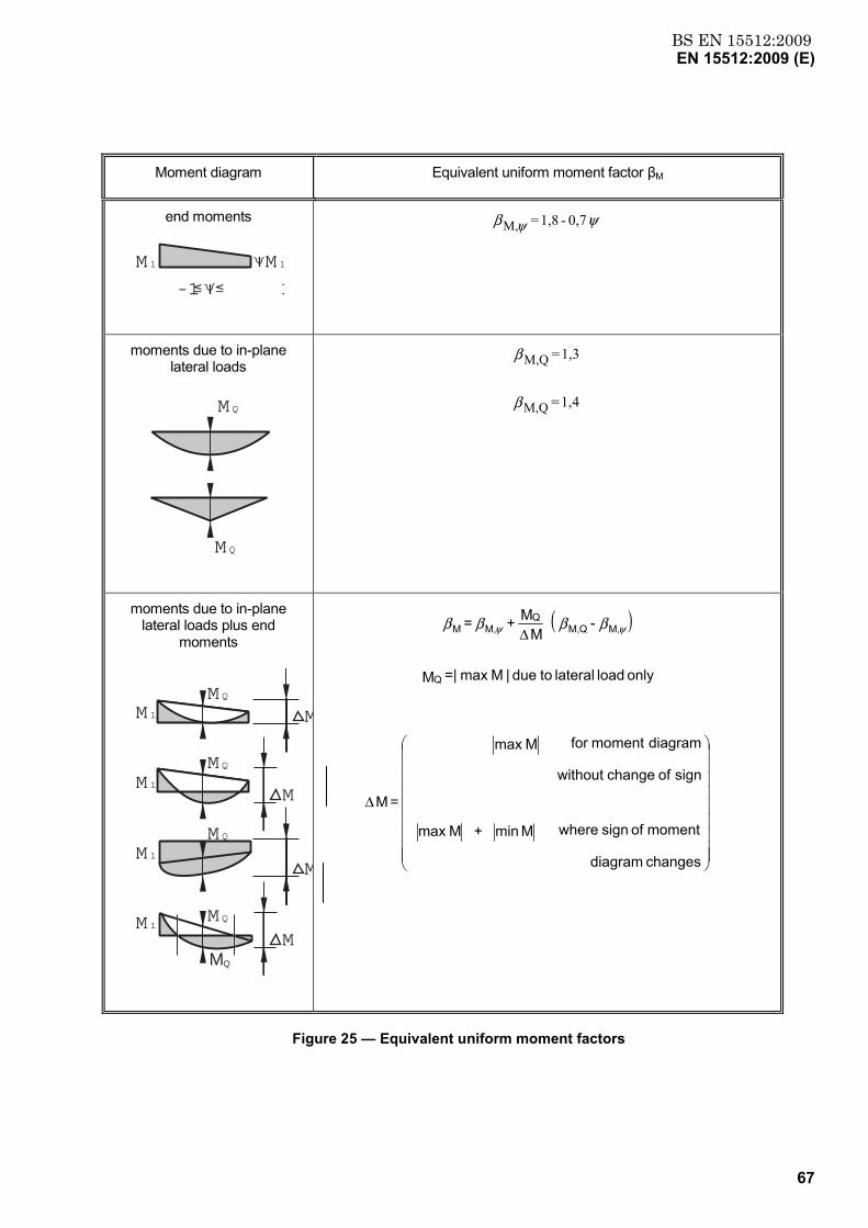
BS EN 15512:2009EN 15512:2009 (E)
67
Moment diagram Equivalent uniform moment factor βM
end moments
-1 1
M 1 M 1
ψβ ψ 0,7 - 1,8 = M,
moments due to in-plane lateral loads
M Q
M Q
41, =
1,3 =
QM,
QM,
β
β
moments due to in-plane lateral loads plus end
moments
MMQ
M
M
MM Q
M 1
M 1
M 1
M 1
M Q
M Q
M Q
( )
∆
∆
changes diagram
moment of sign where M min + Mmax
sign of change without
diagram moment for Mmax
= M
only load lateral to due |Mmax =| M
- M
M + =
Q
M,QM,Q
M,M ββββ ψψ
Figure 25 — Equivalent uniform moment factors
BS EN 15512:2009EN 15512:2009 (E)
68
9.7.6.5 Bending and axial tension
9.7.6.5.1 Tension only
Hot rolled tension members shall be designed in accordance with Clause 6.2.3 of EN 1993-1-1.
Cold formed tension members shall be designed in accordance with Clause 6.1.2 of EN 1993-1-3.
9.7.6.5.2 Combined bending and tension
For members in combined bending and tension, the following condition shall be satisfied:
1 MM
+ M
M +
NN
Rdcz,
Sdz,
Rdcy,
Sdy,
Rdt,
Sd ≤ (38)
where:
MSd and NSd are design values of moment and tensile force respectively and the resistance terms are defined in 9.3.2. and 9.7.6.5.1
If the bending moment capacity is determined by plastic design the interaction formula given in EN 1993-1-1 shall be used.
9.8 Design of splices
Splices shall be designed either by calculation or by testing according to A.2.11.
a) Splices shall have as a minimum the strength of the weaker of the connected members, or shall be designed for a concentric compressive force NSd and a bending moment Mj,Sd
.
b) Splices and connections shall be designed in such a way that loads, axial force, shear force and bending moment can be transmitted to the effective portions of the cross-section.
c) If it can be shown by test (see A.2.11) that the stiffness and the moment of resistance of the two uprights connected by the splice are equal or greater than in the upright in one piece and with the same length it is permissible to ignore the presence of the splice in the global analysis.
d) When the constructional details at the ends of a member are such that there is doubt regarding the point of action of the load, a suitable eccentricity Mecc shall be assumed in the design.
e) If a hinged splice is assumed in the global model then only axial strength and shear force may be checked and stiffness need not be checked.
The splice joint shall be designed for:
1 / M
M +
/ f AN
Msp
Sdj,
MyspSd ≤
+
γγeccM
(39)
where
l
xsin Aeff
Weff 1 - 1 NSd + M Sdy, = M Sdj,π
χ
(40)
χ is according to 9.7.4
BS EN 15512:2009EN 15512:2009 (E)
69
Aeff is the area of the effective cross-section of the weaker member;
Weff is the modulus of the effective cross-section in bending of the weaker member;
x is the distance between the point of inflection in buckling and the splice or end connection;
l is the effective length;
Asp is the net cross-sectional area of the splice;
Msp is the moment of resistance of the splice;
Mecc is the moment due to eccentricities.
The internal forces and moments should be taken as not less than a moment equal to 10 % of the moment capacity of the weaker section about both axes and a shear force equal to 1,5 % of the normal force capacity of the weaker section in the directions of both axes. If, in the analysis, the splice is modelled as a pinned connection the minimum value of the moment need not be applied.
9.9 Design of base plates
9.9.1 General
Every upright shall be fixed with a base plate.
Checks shall be carried out on the strength of the base plate, the contact pressure and the holding down bolt.
Determination of the contact pressure and base plate may be carried out under the general action of the normal force. Any moments from the restraint may be ignored.
NOTE The upright to floor connection is generally loaded in compression and bending. However, in determining the rotational spring constant Cfloor according to A.2.7, the influence of this bending moment is already taken into account. Therefore in the base plate design only the compression force should be checked for a concentrically loaded base plate.
9.9.2 Effective area Abas for base plates
The design of a concentrically loaded base plate shall assume that the bearing pressure on the effective area of the base plate is uniformly distributed over the effective area. In Figure 26 the effective area is indicated by the shaded portion, where
f 3f t = e y
bj
(40)
where
tb is the thickness of the base plate;
fy is the design strength of the base plate;
fj is the design strength of the floor material for contact pressure (see 9.10).
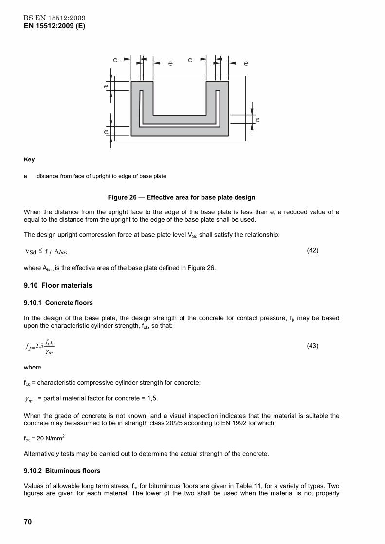
BS EN 15512:2009EN 15512:2009 (E)
70
e e
e
e
e
e e
Key
e distance from face of upright to edge of base plate
Figure 26 — Effective area for base plate design
When the distance from the upright face to the edge of the base plate is less than e, a reduced value of e equal to the distance from the upright to the edge of the base plate shall be used.
The design upright compression force at base plate level VSd shall satisfy the relationship:
A f VSd basj≤ (42)
where Abas is the effective area of the base plate defined in Figure 26.
9.10 Floor materials
9.10.1 Concrete floors
In the design of the base plate, the design strength of the concrete for contact pressure, fj, may be based upon the characteristic cylinder strength, fck, so that:
mck
jffγ
5.2= (43)
where
fck = characteristic compressive cylinder strength for concrete;
γ m = partial material factor for concrete = 1,5.
When the grade of concrete is not known, and a visual inspection indicates that the material is suitable the concrete may be assumed to be in strength class 20/25 according to EN 1992 for which:
fck = 20 N/mm2
Alternatively tests may be carried out to determine the actual strength of the concrete.
9.10.2 Bituminous floors
Values of allowable long term stress, fc, for bituminous floors are given in Table 11, for a variety of types. Two figures are given for each material. The lower of the two shall be used when the material is not properly
BS EN 15512:2009EN 15512:2009 (E)
71
identified and there is uncertainty about its type. If the material has been positively identified, either by expert visual inspection, or by test, the higher value may be used.
If the supplier of the floor material can provide sound evidence to justify higher values of the allowable long term compressive stress, then the higher values may be used in the design.
The relationship between the design stress for the ultimate limit state, fj, and the allowable long term stress, fc, is:
fj = 1,5 fc (44)
The figures given in Table 11 relate to the allowable contact pressure on the top layer, to be used in the design of the base plate.
For any type of bitumen floor the upright to floor connection shall be taken as a pinned joint.
NOTE All layers of the floor construction resist the load from the base plate.
Table 11 — Allowable contact pressures for bituminous industrial floors
Floor type fc(2)
N/mm2
fc(3)
N/mm2
Group Top layer
Conventional asphalt concrete 0,3 0,8
Hot bituminous asphalt Asphalt concrete with polymer modified binder 0,3 0,8
Porous asphalt impregnated with a sand/ cement mixture
0,3 0,8
Stone mastic asphalt 0,3 0,8
Asphalt emulsion Asphalt emulsion + cement + aggregate 0,3 4,0
Cold bituminous asphalt Open structure, on little stability 0,3 -
Mastic asphalt Thermoplastic and visco-elastic 0,3 -
1 The values given in this table are related to the top surface and are valid for temperatures less than 25 0C at floor level.
2. The lower value of fc shall be used if the floor material has not been positively identified.
3. The higher value of fc may be used when the floor material has been positively identified
9.10.3 Other floor materials
In the case of floors which are neither bituminous nor made from concrete, the advice of the supplier of the floor material, concerning its bearing strength, shall be sought. In assessing the characteristic strength of the material, due consideration should be given to the possibility of creep occurring and to the influence of temperature on the behaviour of the material. Attention should be given not only to the surface layers, but also to any sub layers of the floor whose performance can influence the behaviour of the base plate.
9.10.4 Design of anchorages
The design forces in the floor fixings shall be calculated for the most onerous load combination at the ultimate limit state and the anchorages shall be designed in accordance with ETAG No 001.

BS EN 15512:2009EN 15512:2009 (E)
72
Each upright to floor connection shall be able to transfer a minimum un-factored force of 3kN in tension and 5kN in shear.
NOTE For anchorages in concrete, the following parameters are significant:
a) thickness of the structural concrete floor (an added screed will not contribute to the strength of the anchorage);
b) quality of the concrete;
c) percentage of reinforcement in the top of the slab;
d) whether the anchorage is in the tension or compression zone of the concrete;
e) distance between anchors;
f) distance between the anchorage and the edge of the concrete slab;
g) difference between the size of the hole in the base plate and the diameter of the anchorage.
When the concrete slab is placed directly on the soil, the tensile stresses in the upper layers of the concrete are generally small and the top of the slab may be considered as being in the compression zone.
9.11 Design of run spacers
In double entry racks, at least two run spacers (see Figure 2) shall be provided between each adjacent pair of upright frames. These shall be located at the node points of the upright frames and spaced as widely apart as practicable. An additional run spacer shall be provided adjacent to any splice. The lowest spacer shall normally be positioned at the level of the first bracing node next to the lowest bracing node above the floor.
Each run spacer shall have a tensile capacity at least equal to the horizontal placement load.
If the run spacers are taken into account in the design they shall be capable of resisting the forces involved.
10 Global analysis of beam pallet racks
10.1 General considerations
10.1.1 General
The design of the rack system shall be verified in two stages. In the first stage a global analysis of the structure shall be made in order to determine the distribution of internal forces and displacements. In the second stage, individual elements of the structure shall be checked to ensure that they have adequate resistance in the ultimate limit state, and that unacceptable deformations do not develop in the serviceability limit state.
For the purpose of global analysis, system lines coinciding with either the centroidal axes of the gross cross-section of the members or the reduced cross section from which the properties are determined shall be used.
Pallet rack systems are usually fabricated from cold-formed sections and, therefore, elastic methods of global analysis may be used. However, non-linear connection behaviour in the analysis may be used provided that the non-linear characteristic used is based on test results which demonstrate adequate rotation capacity. Alternatively, elastic-plastic analysis may be used if the sections undergoing plastic hinge action satisfy the criteria given in EN 1993-1-1 and EN 1993-1-3 for plastic design including the ductility requirements specified in these codes.
BS EN 15512:2009EN 15512:2009 (E)
73
10.1.2 Two dimensional analysis
Although the pallet rack is a spatial structure, it may be assumed, for the purposes of global analysis, that it can be treated as comprising of a set of plane frames lying in the vertical planes, parallel and perpendicular to the aisles, and in the horizontal plane, each of which is initially taken to operate independently. Imperfections in one plane may be neglected when carrying out the global analysis of the other plane. However, in member design, account shall be taken of effects in one plane which impinge on the behaviour in another, using appropriate interaction equations.
Alternatively, the analysis may be based on a detailed 3-dimensional analysis according to 10.1.3.
The procedures in this section apply to both un-braced and braced racks as described in 5.1.2 and 5.1.3.
10.1.3 Advanced three-dimensional analysis
The global analysis shall be based on a detailed 3-dimensional second-order finite element analysis which takes full account of all of the requirements of this document. The method used shall be broadly in accordance with 5.3.2 (11) of EN 1993-1-1. The analysis shall include the following facilities.
Global imperfections in both the down-aisle and cross-aisle directions.
Member imperfections (initially curved members) shall be those implicit in Clause 5.3.2 (11) of EN 1993-1-1. If the buckling curve is determined by tests according to A.2.3, the value of αLT shall be determined from the test results by curve fitting.
Joint eccentricities, where relevant.
Flexural-torsional buckling of the members.
The influence of warping deformations on torsional buckling (Wagner effect), warping torsion and shear centre eccentricity.
In such cases, local member buckling shall be ignored in detailed member design, i.e. the buckling stress reduction factor χ = 1.
10.2 Design procedure
10.2.1 Actions
10.2.1.1 General
Rack structures shall be designed for the actions defined in Clause 6.
10.2.1.2 Design values
The design value of an action at both the ultimate and serviceability limit state shall be obtained by multiplying the actions by load factors given in 7.4 and the combination factors given in 7.2 and 7.3.
10.2.2 Procedure
10.2.2.1 General
The analysis of a rack system shall be undertaken by considering first the down-aisle direction and then the cross-aisle direction. In order to design the uprights, the forces arising from these two analyses shall be combined using the interaction formulae given in 9.7. Other elements shall be designed on the basis of one or other plane frame analysis as appropriate.
BS EN 15512:2009EN 15512:2009 (E)
74
NOTE The design of the uprights involves combining the axial load arising from the stored materials etc, enhanced by any additional axial loads arising from placement loads etc, with bending moments about both axes of the section. However, in accordance with 5.3.2, sway imperfections and placement loads may be considered in one direction at a time.
10.2.2.2 Load combinations for analysis in the down-aisle direction
In the down-aisle direction, the structure shall be analysed for the following loads in combination:
a) Dead load.
b) Imposed load from stored materials.
c) Imposed load from walkways or floors.
d) Actions arising from imperfections in the down-aisle direction.
e) Imposed load from handling equipment.
f) In considering imposed loads from stored materials, the worst loading pattern shall be considered for each of the following criteria.
g) Overall stability in the down-aisle direction.
h) Bending and buckling of the uprights.
i) Beam deflections and mid-span bending moments.
j) Moments in beam to upright connectors.
For overall stability in the down-aisle direction, the fully loaded structure may be considered with the actions arising from imperfections as specified in 5.3.
For the design of the uprights both the fully loaded condition and the pattern loaded condition shall be considered. It may be sufficient to consider, for a regular rack layout, the pattern loaded case as the structure fully loaded with the exception of a single unloaded beam near the middle of the structure at the lowest level as shown in Figure 27 a). In braced racks, an alternative loading pattern giving rise to single curvature in the uprights shall also be considered as shown in Figure 27 b).
NOTE 1 If the lowest beam is near the ground, it may be more critical to omit the load from a single beam at the second level and the case shown in Figure 27 c) should also be considered.
NOTE 2 This analysis gives rise to primary axial loads and down-aisle bending moments in the uprights. First order analysis may be considered for the design of pattern load cases, when those results are combined with the results of a second order analysis of the fully loaded condition.
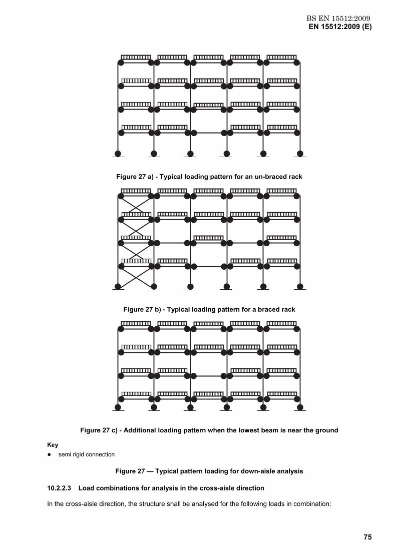
BS EN 15512:2009EN 15512:2009 (E)
75
Figure 27 a) - Typical loading pattern for an un-braced rack
Figure 27 b) - Typical loading pattern for a braced rack
Figure 27 c) - Additional loading pattern when the lowest beam is near the ground
Key ● semi rigid connection
Figure 27 — Typical pattern loading for down-aisle analysis
10.2.2.3 Load combinations for analysis in the cross-aisle direction
In the cross-aisle direction, the structure shall be analysed for the following loads in combination:
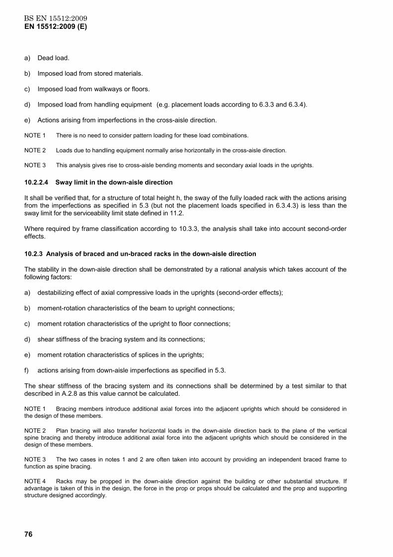
BS EN 15512:2009EN 15512:2009 (E)
76
a) Dead load.
b) Imposed load from stored materials.
c) Imposed load from walkways or floors.
d) Imposed load from handling equipment (e.g. placement loads according to 6.3.3 and 6.3.4).
e) Actions arising from imperfections in the cross-aisle direction.
NOTE 1 There is no need to consider pattern loading for these load combinations.
NOTE 2 Loads due to handling equipment normally arise horizontally in the cross-aisle direction.
NOTE 3 This analysis gives rise to cross-aisle bending moments and secondary axial loads in the uprights.
10.2.2.4 Sway limit in the down-aisle direction
It shall be verified that, for a structure of total height h, the sway of the fully loaded rack with the actions arising from the imperfections as specified in 5.3 (but not the placement loads specified in 6.3.4.3) is less than the sway limit for the serviceability limit state defined in 11.2.
Where required by frame classification according to 10.3.3, the analysis shall take into account second-order effects.
10.2.3 Analysis of braced and un-braced racks in the down-aisle direction
The stability in the down-aisle direction shall be demonstrated by a rational analysis which takes account of the following factors:
a) destabilizing effect of axial compressive loads in the uprights (second-order effects);
b) moment-rotation characteristics of the beam to upright connections;
c) moment rotation characteristics of the upright to floor connections;
d) shear stiffness of the bracing system and its connections;
e) moment rotation characteristics of splices in the uprights;
f) actions arising from down-aisle imperfections as specified in 5.3.
The shear stiffness of the bracing system and its connections shall be determined by a test similar to that described in A.2.8 as this value cannot be calculated.
NOTE 1 Bracing members introduce additional axial forces into the adjacent uprights which should be considered in the design of these members.
NOTE 2 Plan bracing will also transfer horizontal loads in the down-aisle direction back to the plane of the vertical spine bracing and thereby introduce additional axial force into the adjacent uprights which should be considered in the design of these members.
NOTE 3 The two cases in notes 1 and 2 are often taken into account by providing an independent braced frame to function as spine bracing.
NOTE 4 Racks may be propped in the down-aisle direction against the building or other substantial structure. If advantage is taken of this in the design, the force in the prop or props should be calculated and the prop and supporting structure designed accordingly.
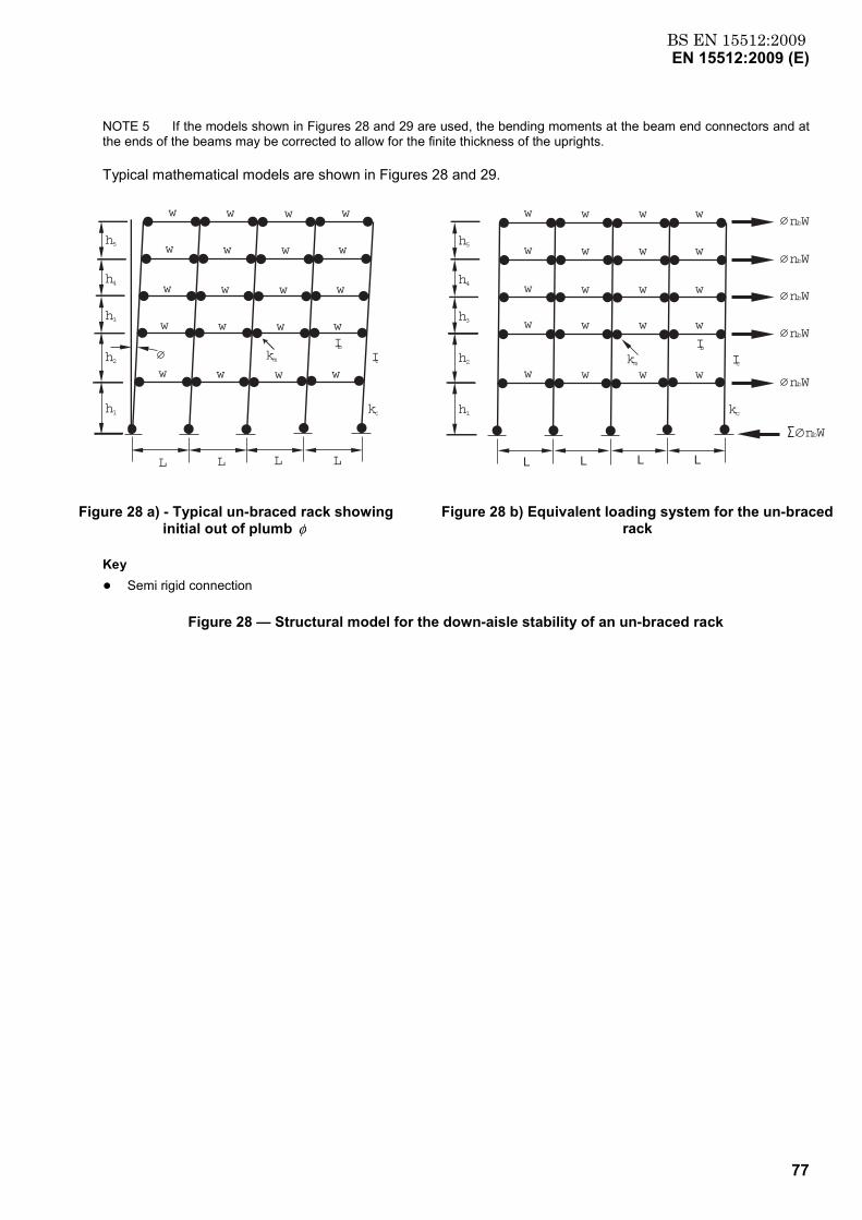
BS EN 15512:2009EN 15512:2009 (E)
77
NOTE 5 If the models shown in Figures 28 and 29 are used, the bending moments at the beam end connectors and at the ends of the beams may be corrected to allow for the finite thickness of the uprights.
Typical mathematical models are shown in Figures 28 and 29.
w
w
w
w
w
w
w
w
w
w
w
w
w
w
w
w
w
w
w
w
L L L L
h2
h1
h3
h4
h5
IbIc
kc
km
L L L L
h2
h1
h3
h4
h5
kmw w w w
w w w w
w w w w
w w w w
w w w w
IcIb
kc
nbW
nbW
nbW
nbW
nbW
nbW
Figure 28 a) - Typical un-braced rack showing initial out of plumb φ
Figure 28 b) Equivalent loading system for the un-braced rack
Key ● Semi rigid connection
Figure 28 — Structural model for the down-aisle stability of an un-braced rack
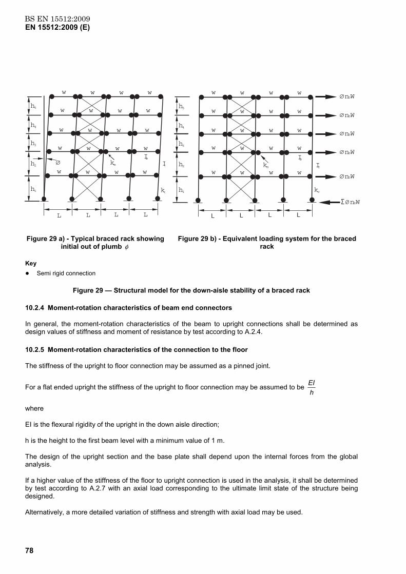
BS EN 15512:2009EN 15512:2009 (E)
78
w
w
w
w
w
w
w
w
w
w
w
w
w
w
w
w
w
w
w
w
L L L L
h2
h1
h3
h4
h5
IbIc
kc
km
L L L L
h2
h1
h3
h4
h5
kmw w w w
w w w w
w w w w
w w w w
w w w w
IcIb
kc
nbW
nbW
nbW
nbW
nbW
nbW
Figure 29 a) - Typical braced rack showing initial out of plumb φ
Figure 29 b) - Equivalent loading system for the braced rack
Key ● Semi rigid connection
Figure 29 — Structural model for the down-aisle stability of a braced rack
10.2.4 Moment-rotation characteristics of beam end connectors
In general, the moment-rotation characteristics of the beam to upright connections shall be determined as design values of stiffness and moment of resistance by test according to A.2.4.
10.2.5 Moment-rotation characteristics of the connection to the floor
The stiffness of the upright to floor connection may be assumed as a pinned joint.
For a flat ended upright the stiffness of the upright to floor connection may be assumed to be hEI
where
EI is the flexural rigidity of the upright in the down aisle direction;
h is the height to the first beam level with a minimum value of 1 m.
The design of the upright section and the base plate shall depend upon the internal forces from the global analysis.
If a higher value of the stiffness of the floor to upright connection is used in the analysis, it shall be determined by test according to A.2.7 with an axial load corresponding to the ultimate limit state of the structure being designed.
Alternatively, a more detailed variation of stiffness and strength with axial load may be used.
BS EN 15512:2009EN 15512:2009 (E)
79
A design check shall be included which takes into account the variation of the strength and the stiffness of the floor connection under variations of axial load.
10.3 Analysis of braced and un-braced racks in the cross-aisle direction
10.3.1 General
The stability in the cross-aisle direction shall be demonstrated by a rational analysis which takes account of the following factors:
a) shear flexibility of the bracing system including the flexibility of the connections between the uprights and the bracing members. This shall be determined by test according to A.2.8;
b) moment-rotation characteristics of splices in the uprights;
c) loads originating from handling equipment;
d) moment-rotation characteristics of the upright to floor connections;
e) overall stability of the braced frame;
f) actions arising from imperfections in the cross-aisle direction as specified in 5.3.3.
A non-zero moment-rotation characteristic may be used if it is assured that full contact with the floor will be maintained.
NOTE 1 It is usual and safe to assume a pinned connection between the uprights and the floor. A typical mathematical model is shown in Figure 30.
NOTE 2 Racks may be propped in the cross-aisle direction against the building or other substantial structure. If advantage is taken of this in the design, the force in the prop or props should be calculated and the prop and supporting structure designed accordingly.
10.3.2 Out of plane stability
Unequal compression loading on the two legs of an upright frame are caused by:
a) initial verticality imperfection;
b) imposed horizontal loading;
c) second-order effects.
The heaviest loaded upright shall be checked for out of plane (down aisle) flexural and torsional buckling. It may be assumed that this check will not be determinative for un-braced pallet racking.
10.3.3 Frame classification
Frame classification is based on the elastic critical load ratio VSd/Vcr
If VSd/Vcr ≤ 0,1, a frame shall be classified as non-sway, i.e. its response to in-plane horizontal forces is sufficiently stiff for it to be acceptably accurate to neglect any additional internal forces or moments arising from horizontal displacement of the nodes. In such a case, a first-order analysis is sufficient. Any other frame shall be classified as a sway frame and the effects of the horizontal displacement of its nodes taken into account in its design.
Methods of estimating Vcr with sufficient accuracy for frame classification are given in Annexes B, C and G.

BS EN 15512:2009EN 15512:2009 (E)
80
NOTE Un-braced racks are invariably classed as sway frames in the down-aisle direction and therefore require consideration of second-order effects.
Levels of analysis are given in 10.4.
If 0,1 < VSd/Vcr ≤ 0,3 a level 2 analysis may be used in which second-order effects are treated indirectly.
If VSd/Vcr > 0,3 a level 1 analysis shall be used in which second-order effects are treated directly.
NOTE The limit at which an accurate second-order analysis becomes mandatory is more generous than that in EN 1993-1-1. This is because pallet racks are industrially produced to higher tolerances than normal construction work, have semi-rigid joints and generally have a regular construction. In these circumstances, the agreement between the exact and approximate methods is much improved so that the range of validity of the approximate methods may be increased.
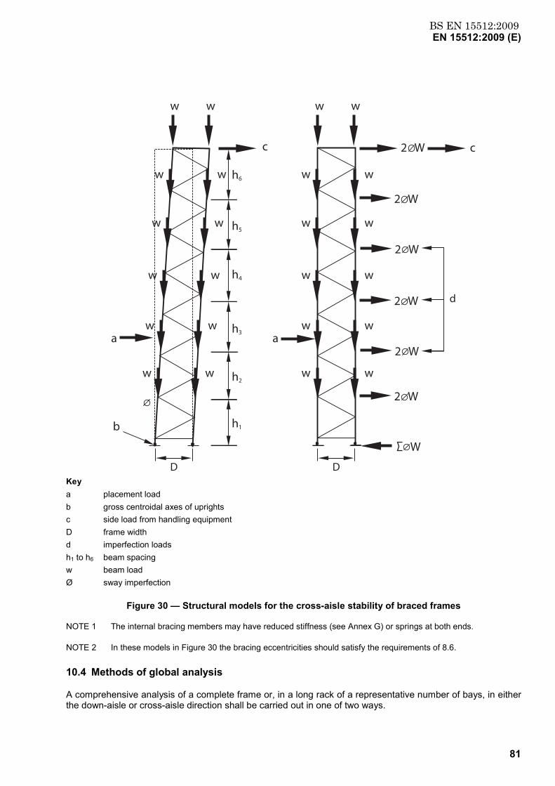
BS EN 15512:2009EN 15512:2009 (E)
81
D
d
h2
h1
h3
h4
h5
h6
2 W
2 W
c
w w w w
w w
w w
w w
w w
wa a
b
c
w
w w
w w
w w
w w
w w
D
2 W
2 W
W
2 W
2 W
Key a placement load b gross centroidal axes of uprights c side load from handling equipment D frame width d imperfection loads h1 to h6 beam spacing w beam load Ø sway imperfection
Figure 30 — Structural models for the cross-aisle stability of braced frames
NOTE 1 The internal bracing members may have reduced stiffness (see Annex G) or springs at both ends.
NOTE 2 In these models in Figure 30 the bracing eccentricities should satisfy the requirements of 8.6.
10.4 Methods of global analysis
A comprehensive analysis of a complete frame or, in a long rack of a representative number of bays, in either the down-aisle or cross-aisle direction shall be carried out in one of two ways.
BS EN 15512:2009EN 15512:2009 (E)
82
Level 1: Using second-order elastic or elastic-plastic analysis in which the structural components are represented by prismatic members and the connections have appropriate moment-rotation characteristics.
There are two alternative treatments of the flexibility of the beam-end connectors.
1) The beam-upright connectors may be modelled as rotational springs of constant stiffness. In this case, the looseness of the beam-upright connectors shall be incorporated in the frame imperfections according to 5.3.2.
2) The beam-upright connectors may be modelled as non-linear rotational springs. In this case, the looseness of the beam-upright connectors may either be incorporated in the global analysis by including an appropriate initial looseness in the non-linear spring characteristic or it shall be incorporated in the frame imperfections according to 5.3.2.
Level 2: Using first-order elastic analysis in which the structural components are represented by prismatic members and the connections by springs and in which the second-order effects are treated indirectly by one of the following methods.
3) Using amplified sway moments as described in Annex B, whereby the sway moments found by a first order elastic analysis are increased by multiplying them by the ratio.
V - VV
Sdcrcr (45)
When the amplified sway moments method is used, in-plane buckling lengths for the non-sway mode shall be used for member design.
4) The method given in Annex C which uses simplified equations may be regarded as a version of the amplified sway moments method and is subject to the same requirements.
5) Any other rational simplification of second order effects provided that the method is calibrated against a full second order analysis and shown to be conservative over the range of structures for which it is to be used.
If the methods of Annexes B or C are used and if there is a splice below the third beam level, either it shall be demonstrated that the splice does not introduce any loss of stiffness or a full second-order analysis shall be carried out taking account of the flexibility of the splice.
NOTE 1 Sway moments are those associated with the horizontal translation of one beam level relative to the beam level below. They arise from horizontal loading and may also arise from vertical loading if either the structure or loading is asymmetrical.
NOTE 2 If all of the bays have the same configuration of beam levels, the lesser of either five bays or the actual number may be used
NOTE 3 The simplified method in Annex C may only be used for standard pallet rack arrangements which conform to the following requirements:
a) constant beam length;
b) approximately constant height between beam levels except for the first storey;
c) the same upright section throughout the rack;
d) the same beam section throughout the rack;
e) no change of beam levels within the length of the rack;
f) the same beam end connector type throughout the rack.
BS EN 15512:2009EN 15512:2009 (E)
83
NOTE 4 If it can be shown that a splice in this position has rotational stiffness, moment capacity and strength equal or greater than that of the weaker upright in the joint with the same length its effects may be ignored in global analysis.
10.5 Simplified methods of analysis for stability in the cross-aisle direction
A level 2 method is described in Annex G which is based on the amplified sway moments method.
10.6 Design of uprights
10.6.1 General
It shall be verified that, at the ultimate limit state, uprights satisfy the requirements of 9.7 when subject to the loads given in Clause 6.
10.6.2 Design axial forces and bending moments
The axial forces and bending moments calculated for the ultimate limit state shall be used directly in the appropriate interaction formulae given in 9.7.6 but account shall be taken of any out-of-plane effects which arise from the overall behaviour of the structure.
NOTE 1 The design axial force in a member is the vertical force due to the applied loading augmented by any additional effects due to sway in both directions which may, in turn, be augmented by the influence of imperfections, placement loads, second-order effects, etc (see 7.1). This axial force should be combined with the design bending moments about both axes.
NOTE 2 The critical design case for an upright may be complicated by the fact that second-order effects in one plane may be enhanced by second-order effects in the other plane. In general, this interaction need not be taken into account. Thus, the design axial load for an upright may be enhanced by second-order effects with imperfections in one plane and second-order effects without imperfections in the other plane. If this design results in a higher axial load than that used in the relevant second-order analysis, there is no need to repeat this analysis.
NOTE 3 In a braced structure, the axial forces and bending moments arising from a first-order analysis at the ultimate limit state should be used directly in the interaction formulae. The critical uprights in braced frames are those adjacent to the bracing.
NOTE 4 The axial forces in the uprights of braced bays are influenced by overturning moments due to frame imperfections, etc. This will increase the axial load in one upright and may give rise to an uplift force at the foot of the other upright. This uplift force should be resisted by the holding down bolts in the base plate.
11 Serviceability limit states
11.1 General
A steel structure shall be designed and constructed such that all relevant serviceability criteria are satisfied.
In general, deformations or deflections which affect the appearance or effective use of the structure should be considered.
Where plastic global analysis is used for the ultimate limit state, plastic redistribution of forces and moments at the serviceability limit state can occur. When this is the case, it should be verified that the serviceability limit state criteria remain valid.
11.2 Serviceability limit states for racking
Deflections shall be calculated taking into account the loads defined in Clause 6 and the serviceability limit state load and combination factors given in 5.2.3, 7.3 and 7.4.
BS EN 15512:2009EN 15512:2009 (E)
84
Limiting deflection values shall be agreed with the specifier on a project by project basis, taking into account the specific requirements of the installation.
Deformation limits in relation to safe operation conditions are given in EN 15620.
In the absence of any specific requirements, the following limiting deflection values should be used:
a) maximum twist in a beam (see 8.5.6):
6 degrees;
b) maximum vertical deflection in the supporting structure of a walkway or rack supported floor:
span/250.
The limit of span/250 for structures supporting walkways or rack supported floors is applicable to a load of 2,5 kN/m2 (see 6.3.6). If a higher load is specified a higher deflection limit in proportion may be allowed but should not be more than span/200.
12 Marking and labelling
12.1 Identification of performance of rack installations
All installations shall display, in one or more conspicuous locations, a permanent notice stating that the rack is designed according to this document and shows the maximum permissible weight of unit load and the maximum permissible bay load in clear legible print. Where racking also supports flooring or walkways, the permissible loads, (e.g. storage loads or the wheel loads of mechanical handling equipment) shall also be displayed (see EN 15635).
Where the permissible loads are not identical throughout the installation, load notices shall be placed so that the maximum permissible weight of unit load is identified for each location throughout the structure.
13 Test methods and evaluation of results
13.1 General
Where tests are carried out for the purpose of obtaining performance data for use in design these shall be in accordance with Annex A.
Guidance on suitable factory production control regimes in order to satisfy the requirements of this document is given in Annex H.
Unless the specific requirements for a test require otherwise, any value of strength, stiffness or deformation to be determined shall be derived from at least three experimental results. The test components shall be taken from normal production and fully finished in accordance with the normal specification.
Table 12 gives an overview of the design tests specified in Annex A.
NOTE Manufacturers may select steel grades which are close to the nominal yield stress.
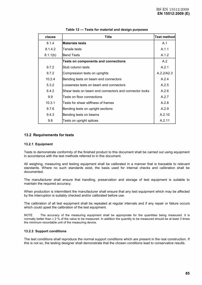
BS EN 15512:2009EN 15512:2009 (E)
85
Table 12 — Tests for material and design purposes
clause Title Test method
8.1.4
8.1.4.2
8.1.1(b)
Materials tests
Tensile tests
Bend Tests
A.1
A.1.1
A.1.2
9.7.2
9.7.2
10.2.4
5.3.2
6.4.2
9.9
10.3.1
9.7.6
9.4.3
9.8
Tests on components and connections
Stub column tests
Compression tests on uprights
Bending tests on beam end connectors
Looseness tests on beam end connectors
Shear tests on beam end connectors and connector locks
Tests on floor connections
Tests for shear stiffness of frames
Bending tests on upright sections
Bending tests on beams
Tests on upright splices
A.2
A.2.1
A.2.2/A2.3
A.2.4
A.2.5
A.2.6
A.2.7
A.2.8
A.2.9
A.2.10
A.2.11
13.2 Requirements for tests
13.2.1 Equipment
Tests to demonstrate conformity of the finished product to this document shall be carried out using equipment in accordance with the test methods referred to in this document.
All weighing, measuring and testing equipment shall be calibrated in a manner that is traceable to relevant standards. Where no such standards exist, the basis used for internal checks and calibration shall be documented.
The manufacturer shall ensure that handling, preservation and storage of test equipment is suitable to maintain the required accuracy.
When production is intermittent the manufacturer shall ensure that any test equipment which may be affected by the interruption is suitably checked and/or calibrated before use.
The calibration of all test equipment shall be repeated at regular intervals and if any repair or failure occurs which could upset the calibration of the test equipment.
NOTE The accuracy of the measuring equipment shall be appropriate for the quantities being measured. It is normally better than ± 2 % of the value to be measured. In addition the quantity to be measured should be at least 3 times the minimum recordable unit of the measuring device.
13.2.2 Support conditions
The test conditions shall reproduce the normal support conditions which are present in the real construction. If this is not so, the testing designer shall demonstrate that the chosen conditions lead to conservative results.
BS EN 15512:2009EN 15512:2009 (E)
86
13.2.3 Application of the load
The test load shall be applied in such a manner that no abnormal influence on, or prevention of deformations can occur.
13.2.4 Increments of the test load
The loads shall either be applied incrementally or continuously. When the load is applied incrementally, the first four increments shall be increments of approximately 5 % of the expected failure load, and the remaining increments shall be chosen so that the behaviour that is under observation is clearly defined.
Deformations at critical points on the test structure shall be observed when they have stabilised.
When the load is applied continuously, the rate of loading shall be slow enough to ensure that static conditions prevail. Deformations shall be observed at regular intervals, and frequently enough to define the behaviour clearly.
13.2.5 Assembly of test specimens
Test specimens shall be assembled in accordance with the manufacturer's assembly instructions.
13.2.6 Test reports
For each test series, formal documentation shall be prepared giving all the relevant data, so that the test series can be accurately reproduced.
The results of inspections, tests or assessments requiring action shall be recorded, as shall any action taken. The action to be taken when control values or criteria are not met shall be recorded.
In addition to the test results, the following minimum information shall also be recorded:
a) Date of manufacture.
b) Product drawing numbers for the components under test.
c) Details of the production and assembly process.
d) Material specification for the components under test.
e) Date of testing.
f) Actual dimensions of test components.
g) Actual material properties of test components.
h) Details of the test arrangement (dimensions, support conditions, connections, etc).
i) Measurements made during the test (load, deflection, rotation, strain, etc).
j) Observations regarding the onset of visible deformations (buckling, tearing, etc).
k) Mode of failure.
l) Photographic evidence of the test in progress.
BS EN 15512:2009EN 15512:2009 (E)
87
13.3 Interpretation of test results
13.3.1 Definition of failure load
The test component shall be deemed to have failed when:
a) the applied test loads reach their upper limit;
b) deformations have occurred of such a magnitude that the component can no longer perform its design function.
13.3.2 Corrections to test results
Raw test results shall be adjusted to account for differences between the actual thickness of the material used in the test and the nominal thickness specified by the manufacturer, and to account for the difference between the yield stress of the material in the test sample and the minimum yield stress guaranteed by the manufacturer. The way in which adjustments are to be made depends upon the nature of the test being made, and is described for each test separately in A.2.
When samples are prepared for tensile tests to determine the yield stress of the material, they shall be cut from an undamaged region of the test piece, away from heat affected zones, and away from bends in the section and from other areas where cold working effects can influence the result.
NOTE Alternatively the test pieces may be cut from the original coil, before cold forming.
13.3.3 Derivation of characteristic values
After the individual results of a group of tests have each been corrected for variations in thickness and yield stress, the characteristic value of the parameter being measured, Rk, shall be calculated as follows:
Rk = Rm - ks s (46)
where
Rm = the mean value of the adjusted test results;
Rm = R 1 = i
n
n1
ni∑
Rni = individual test result, corrected for thickness and yield stress;
n = number of tests results in the group ( )3 n ≥ ;
s = the standard deviation of the adjusted test results;
s = ( ) ( )R - R 1 = i
n
1 - n1
mni2∑
ks = coefficient given in Table 13.
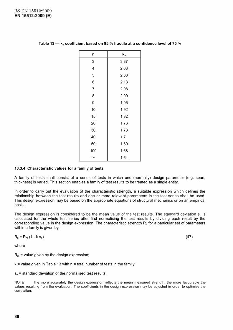
BS EN 15512:2009EN 15512:2009 (E)
88
Table 13 — ks coefficient based on 95 % fractile at a confidence level of 75 %
n ks
3
4
5
6
7
8
9
10
15
20
30
40
50
100
∞
3,37
2,63
2,33
2,18
2,08
2,00
1,95
1,92
1,82
1,76
1,73
1,71
1,69
1,68
1,64
13.3.4 Characteristic values for a family of tests
A family of tests shall consist of a series of tests in which one (normally) design parameter (e.g. span, thickness) is varied. This section enables a family of test results to be treated as a single entity.
In order to carry out the evaluation of the characteristic strength, a suitable expression which defines the relationship between the test results and one or more relevant parameters in the test series shall be used. This design expression may be based on the appropriate equations of structural mechanics or on an empirical basis.
The design expression is considered to be the mean value of the test results. The standard deviation sn is calculated for the whole test series after first normalising the test results by dividing each result by the corresponding value in the design expression. The characteristic strength Rk for a particular set of parameters within a family is given by:
Rk = Rm (1 - k sn) (47)
where
Rm = value given by the design expression;
k = value given in Table 13 with n = total number of tests in the family;
sn = standard deviation of the normalised test results.
NOTE The more accurately the design expression reflects the mean measured strength, the more favourable the values resulting from the evaluation. The coefficients in the design expression may be adjusted in order to optimise the correlation.
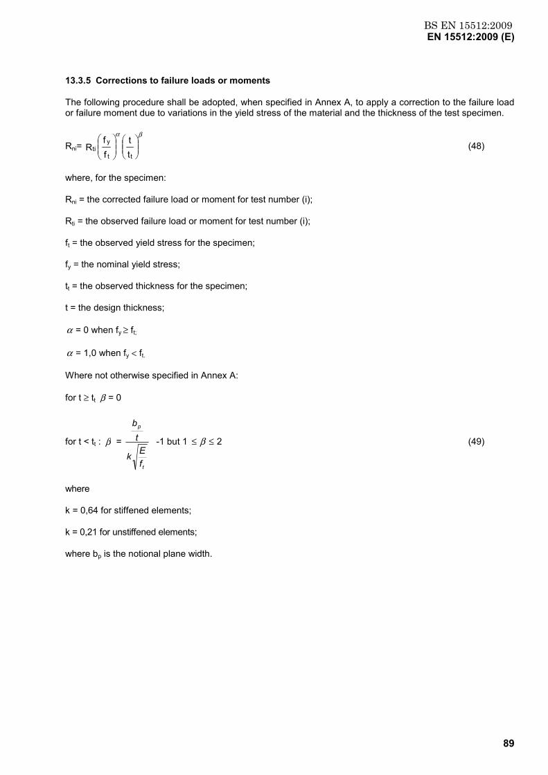
BS EN 15512:2009EN 15512:2009 (E)
89
13.3.5 Corrections to failure loads or moments
The following procedure shall be adopted, when specified in Annex A, to apply a correction to the failure load or failure moment due to variations in the yield stress of the material and the thickness of the test specimen.
Rni=
tt
ff R
tt
yti
βα
(48)
where, for the specimen:
Rni = the corrected failure load or moment for test number (i);
Rti = the observed failure load or moment for test number (i);
ft = the observed yield stress for the specimen;
fy = the nominal yield stress;
tt = the observed thickness for the specimen;
t = the design thickness;
α = 0 when fy ≥ ft;
α = 1,0 when fy < ft.
Where not otherwise specified in Annex A:
for t ≥ tt β = 0
for t < tt : β =
t
p
fEk
tb
-1 but 1 2≤≤ β (49)
where
k = 0,64 for stiffened elements;
k = 0,21 for unstiffened elements;
where bp is the notional plane width.
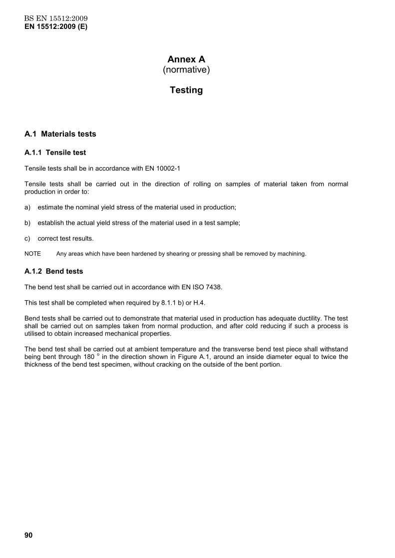
BS EN 15512:2009EN 15512:2009 (E)
90
Annex A (normative)
Testing
A.1 Materials tests
A.1.1 Tensile test
Tensile tests shall be in accordance with EN 10002-1
Tensile tests shall be carried out in the direction of rolling on samples of material taken from normal production in order to:
a) estimate the nominal yield stress of the material used in production;
b) establish the actual yield stress of the material used in a test sample;
c) correct test results.
NOTE Any areas which have been hardened by shearing or pressing shall be removed by machining.
A.1.2 Bend tests
The bend test shall be carried out in accordance with EN ISO 7438.
This test shall be completed when required by 8.1.1 b) or H.4.
Bend tests shall be carried out to demonstrate that material used in production has adequate ductility. The test shall be carried out on samples taken from normal production, and after cold reducing if such a process is utilised to obtain increased mechanical properties.
The bend test shall be carried out at ambient temperature and the transverse bend test piece shall withstand being bent through 180 o in the direction shown in Figure A.1, around an inside diameter equal to twice the thickness of the bend test specimen, without cracking on the outside of the bent portion.
BS EN 15512:2009EN 15512:2009 (E)
91
a
Key a = direction of rolling
Figure A.1 — Transverse bend test piece after bending
The sample shall be deemed to have satisfied the requirements of this document, if a visual inspection of the test piece shows no cracking on the outer surface of the 180 o bend away from the ends. Some local cracking, near the bend but extending no more than 1 mm from the edge of the test piece, is admissible.
A.2 Tests on components and connections
A.2.1 Stub column compression test
A.2.1.1 Purpose of the test
The test shall be used to observe the influence of such factors as perforations and local buckling on the compressive strength of a short column. This test shall not be used to observe the influence of distortional buckling.
A.2.1.2 Test arrangement and method - Alternative 1
The test specimen shall be prepared as follows and as shown in Figure A.2.
a) Its length shall be greater than three times the greatest flat width of the section (ignoring intermediate stiffeners). It shall include at least five pitches of the perforations.
b) It shall be cut normal to the longitudinal axis, midway between two sets of perforations.
c) The base and cap plates shall be bolted or welded to each end of the stub upright.
NOTE The section may be adjusted for spring back (distortion of the shape of the cross-section after cutting due to residual stresses) by welding to the base plate.
The axial load shall be transmitted to the base and cap plates via pressure pads sufficiently thick to ensure that deformations of the pads under the test load do not influence the test result. The pressure pads shall protrude at least 10 mm beyond the perimeter of the upright section. Base and cap plates shall be positively located on the pressure pads at each end. The pressure pads shall have a small indentation drilled to receive a ball bearing, as shown in Figure A.2.
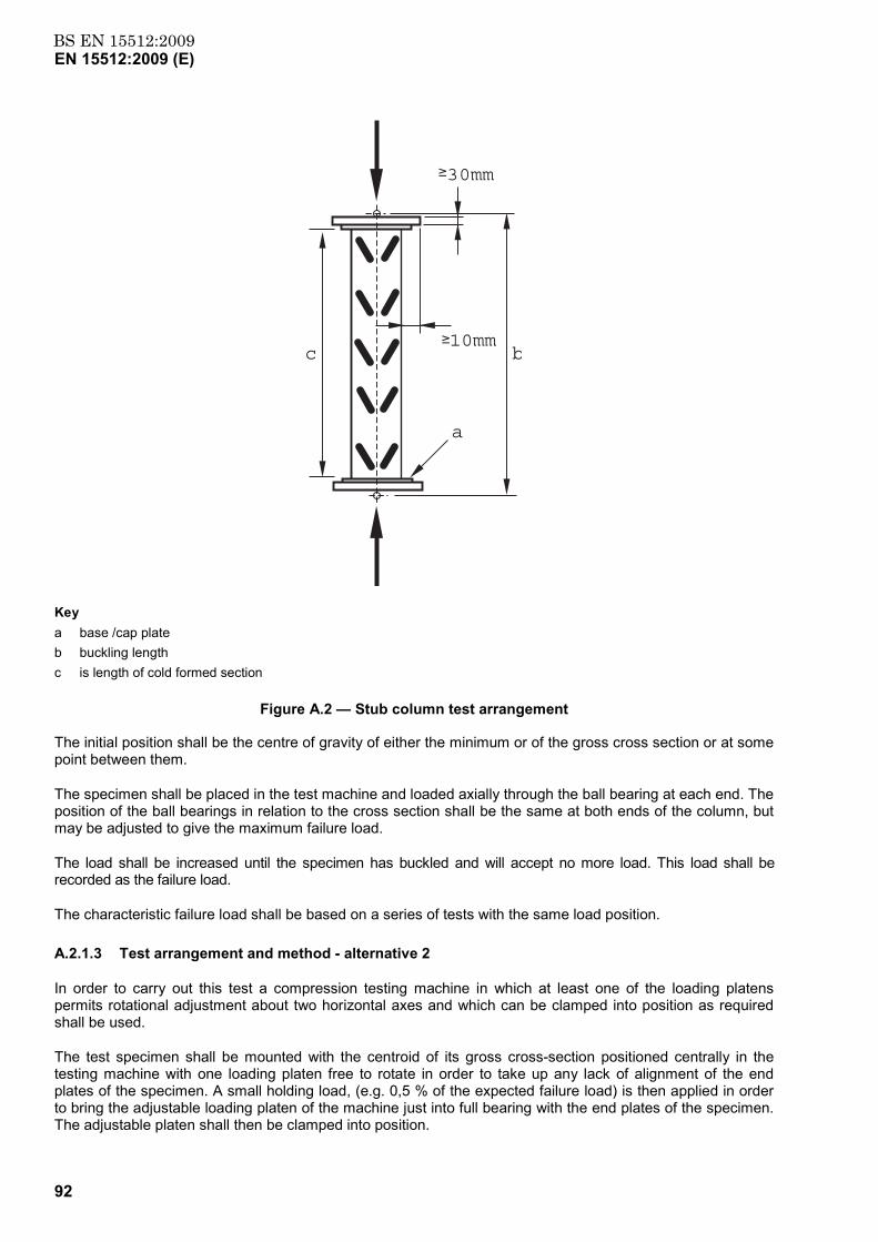
BS EN 15512:2009EN 15512:2009 (E)
92
10mm
30mm
a
bc
Key a base /cap plate b buckling length c is length of cold formed section
Figure A.2 — Stub column test arrangement
The initial position shall be the centre of gravity of either the minimum or of the gross cross section or at some point between them.
The specimen shall be placed in the test machine and loaded axially through the ball bearing at each end. The position of the ball bearings in relation to the cross section shall be the same at both ends of the column, but may be adjusted to give the maximum failure load.
The load shall be increased until the specimen has buckled and will accept no more load. This load shall be recorded as the failure load.
The characteristic failure load shall be based on a series of tests with the same load position.
A.2.1.3 Test arrangement and method - alternative 2
In order to carry out this test a compression testing machine in which at least one of the loading platens permits rotational adjustment about two horizontal axes and which can be clamped into position as required shall be used.
The test specimen shall be mounted with the centroid of its gross cross-section positioned centrally in the testing machine with one loading platen free to rotate in order to take up any lack of alignment of the end plates of the specimen. A small holding load, (e.g. 0,5 % of the expected failure load) is then applied in order to bring the adjustable loading platen of the machine just into full bearing with the end plates of the specimen. The adjustable platen shall then be clamped into position.
BS EN 15512:2009EN 15512:2009 (E)
93
The preparation of the stub column specimens for this test method is the same as in A.2.1.2 except that, in c), no indentations are required in the pressure pads.
The load shall be increased in increments up to failure and the maximum load carried shall be recorded.
A.2.1.4 Corrections to the observations
The observed failure loads shall be adjusted to take account of the actual thickness and yield stress of the test sample in accordance with 13.3.5.
A.2.1.5 Derivation of the results
The characteristic failure load, Rk, shall be derived in accordance with 13.3.3 and the effective area of the cross-section, Aeff, calculated from:
Aeff =fR
y
k (A.1)
If in the stub column test the maximum slenderness of the upright exceeds the value of λ = 0,2, the effective area may be adjusted as follows:
The minimum axial load capacity Nb,Rd,min due to flexural buckling and flexural torsional buckling according to 9.7.4 and 9.7.5 shall be calculated using the value of Aeff obtained from the tests. The value of Aeff shall then be adjusted to a new value until the calculated value of Nb,Rd,min = Rk / γM.
In this process, if the test results have been obtained using alternative 1 in A.2.1.2, the flexural buckling lengths shall be taken equal to the distance, b, between the bearings and the torsional buckling length shall be equal to half the length of cold formed section in the test piece. When alternative 2 in A.2.1.3 is used, the flexural and torsional buckling lengths shall all be equal to half the length of the cold formed section c (see Figure A.2) in the test piece.
A.2.2 Compression tests on uprights - Checks for the effects of distortional buckling
A.2.2.1 Purpose of the test
The purpose of the test is to determine the influence of the distortional buckling mode on the axial load capacity of the upright section. The test result provides a means of correcting the theoretically determined axial load capacity according to 9.7.2.
NOTE If compression tests of uprights according to this Annex are carried out over the complete range of upright lengths, the effects of distortional buckling are included in the buckling curves so that tests according to this section need not be carried out.
A.2.2.2 Test arrangement and method
At least three tests should be carried on single uprights with cap plates as described in A.2.1.2. The uprights should have a length as defined in 9.7.2 c). The test may also be made on a single panel frame as part of a series of tests made to determine the buckling curve for the upright, described in A.2.3.
If significant twisting is observed at the ends of the specimen, the ends should be restrained in order to resist this twisting; this restraint should not offer any additional resistance to distortion of the section.
The specimen shall be placed in the test machine and loaded axially through the ball bearing at each end. The position of the ball bearings in relation to the cross section shall be the same at both ends of the column, but may be adjusted to the position which gives the maximum failure load.
BS EN 15512:2009EN 15512:2009 (E)
94
A.2.2.3 Derivation of the test results
The results of these tests shall be corrected for yield stress and thickness in accordance with A.2.3.4.
The characteristic failure load, Rk, shall then be derived as described in 13.3.3 and the corresponding design strength, Ndb,Rd calculated. This test value is used in 9.7.2 to check for the effects of distortional buckling.
A.2.3 Compression tests on uprights - Determination of buckling curves
A.2.3.1 Purpose of the test
The purpose of this test is to determine the axial load capacity of the upright section for a range of effective lengths in the down-aisle direction, taking account of all buckling effects and the restraint provided by the bracing, its spacing between nodes and its connection to the uprights.
NOTE The results of this test series provide a column curve which is a plot of the buckling reduction factor χ and the
non-dimensional slenderness ratio λ . The value of λ is always obtained from the slenderness corresponding to the out-of-plane buckling mode = (L/i), even when the failure mode is a distortional, flexural-torsional or in-plane buckling mode. The purpose of this is to allow the column curve to be used in the design and relating buckling loads to down-aisle buckling lengths alone. It may be noted that it is conservative in that no account is taken of the restraining effects of the beam end connectors.
A.2.3.2 Test arrangement
The test arrangement comprises a frame assembly using the maximum frame width specified for the product, in which one of the two uprights is loaded axially, as shown in Figure A.3. The bracing pattern, the bracing sections and the bracing connections shall be the components used in the application specific to the buckling curves. The loaded upright shall be loaded through ball bearings and fitted with base and cap plates as described in A.2.1.2.
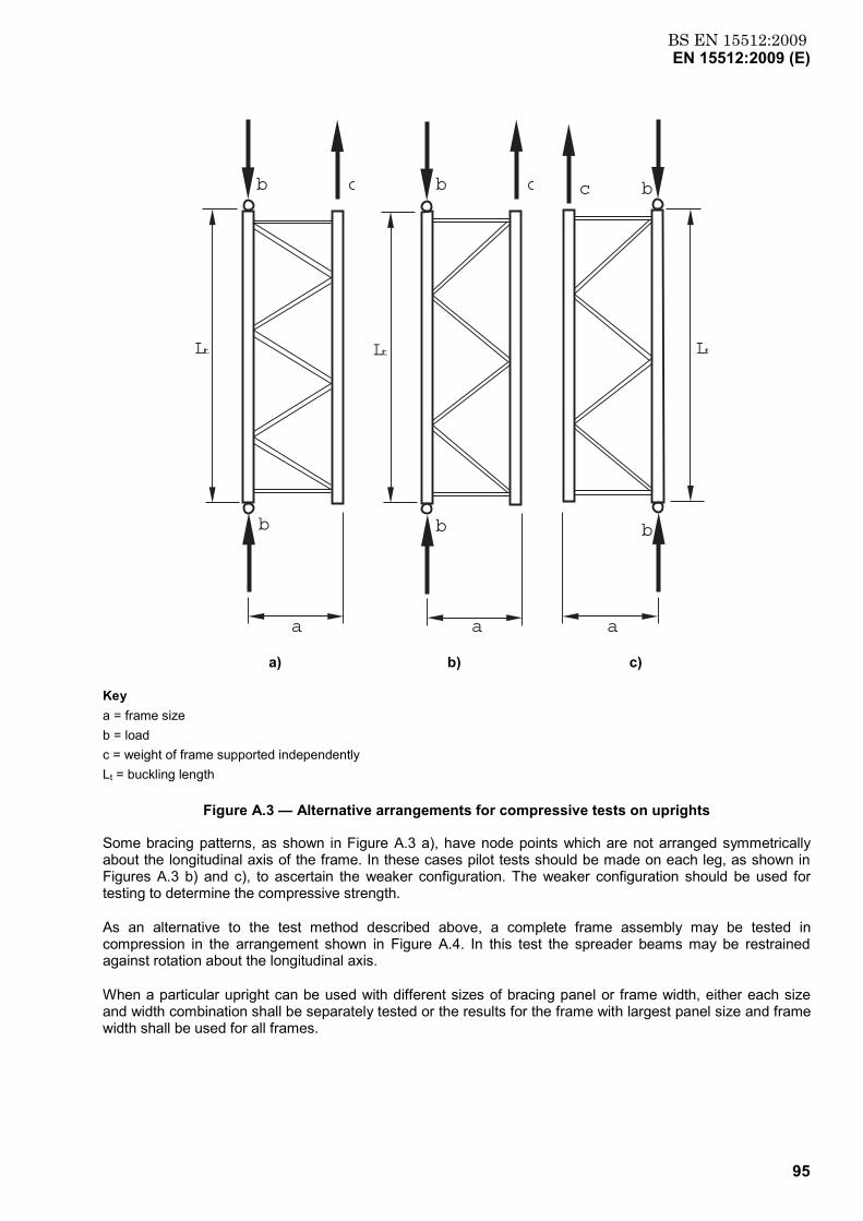
BS EN 15512:2009EN 15512:2009 (E)
95
a
b
b
c
Lt
a)
a
Lt
b
b
c
b)
a
Lt
b
b
c
c)
Key a = frame size b = load c = weight of frame supported independently Lt = buckling length
Figure A.3 — Alternative arrangements for compressive tests on uprights
Some bracing patterns, as shown in Figure A.3 a), have node points which are not arranged symmetrically about the longitudinal axis of the frame. In these cases pilot tests should be made on each leg, as shown in Figures A.3 b) and c), to ascertain the weaker configuration. The weaker configuration should be used for testing to determine the compressive strength.
As an alternative to the test method described above, a complete frame assembly may be tested in compression in the arrangement shown in Figure A.4. In this test the spreader beams may be restrained against rotation about the longitudinal axis.
When a particular upright can be used with different sizes of bracing panel or frame width, either each size and width combination shall be separately tested or the results for the frame with largest panel size and frame width shall be used for all frames.
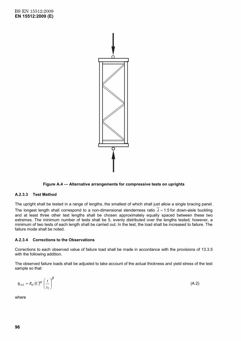
BS EN 15512:2009EN 15512:2009 (E)
96
Figure A.4 — Alternative arrangements for compressive tests on uprights
A.2.3.3 Test Method
The upright shall be tested in a range of lengths, the smallest of which shall just allow a single bracing panel. The longest length shall correspond to a non-dimensional slenderness ratio 5.1≈λ for down-aisle buckling and at least three other test lengths shall be chosen approximately equally spaced between these two extremes. The minimum number of tests shall be 5, evenly distributed over the lengths tested; however, a minimum of two tests of each length shall be carried out. In the test, the load shall be increased to failure. The failure mode shall be noted.
A.2.3.4 Corrections to the Observations
Corrections to each observed value of failure load shall be made in accordance with the provisions of 13.3.5 with the following addition.
The observed failure loads shall be adjusted to take account of the actual thickness and yield stress of the test sample so that:
( )
=
tt C R t
i
βα
tin R (A.2)
where
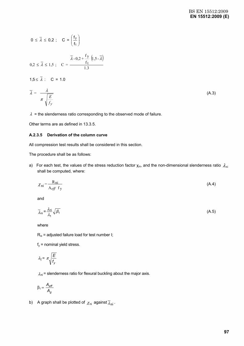
BS EN 15512:2009EN 15512:2009 (E)
97
≤≤
ff = C ; 0,2 0
t
yλ
( )1.3
- 1,5 f
f + 0,2 -
= C ; 1,5 0,2 t
y λλλ ≤≤
1.0 = C : 51, λ≤
= λ
yfE
π
λ (A.3)
λ = the slenderness ratio corresponding to the observed mode of failure.
Other terms are as defined in 13.3.5.
A.2.3.5 Derivation of the column curve
All compression test results shall be considered in this section.
The procedure shall be as follows:
a) For each test, the values of the stress reduction factor χni, and the non-dimensional slenderness ratio λni shall be computed, where:
f AR =
yni
nieff
χ (A.4)
and
11
nini = β
λλ
λ (A.5)
where
Rni = adjusted failure load for test number I;
fy = nominal yield stress.
1λ = yfEπ
λni = slenderness ratio for flexural buckling about the major axis.
β1 = g
eff
AA
b) A graph shall be plotted of χni against λni .
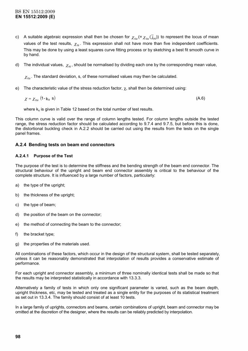
BS EN 15512:2009EN 15512:2009 (E)
98
c) A suitable algebraic expression shall then be chosen for ))( (= nicucu λχχ to represent the locus of mean values of the test results, χni . This expression shall not have more than five independent coefficients. This may be done by using a least squares curve fitting process or by sketching a best fit smooth curve in by hand.
d) The individual values, χni , should be normalised by dividing each one by the corresponding mean value,
χcu . The standard deviation, s, of these normalised values may then be calculated.
e) The characteristic value of the stress reduction factor, χ, shall then be determined using:
( )s k - 1 scuχχ = (A.6)
where ks is given in Table 12 based on the total number of test results.
This column curve is valid over the range of column lengths tested. For column lengths outside the tested range, the stress reduction factor should be calculated according to 9.7.4 and 9.7.5, but before this is done, the distortional buckling check in A.2.2 should be carried out using the results from the tests on the single panel frames.
A.2.4 Bending tests on beam end connectors
A.2.4.1 Purpose of the Test
The purpose of the test is to determine the stiffness and the bending strength of the beam end connector. The structural behaviour of the upright and beam end connector assembly is critical to the behaviour of the complete structure. It is influenced by a large number of factors, particularly:
a) the type of the upright;
b) the thickness of the upright;
c) the type of beam;
d) the position of the beam on the connector;
e) the method of connecting the beam to the connector;
f) the bracket type;
g) the properties of the materials used.
All combinations of these factors, which occur in the design of the structural system, shall be tested separately, unless it can be reasonably demonstrated that interpolation of results provides a conservative estimate of performance.
For each upright and connector assembly, a minimum of three nominally identical tests shall be made so that the results may be interpreted statistically in accordance with 13.3.3.
Alternatively a family of tests in which only one significant parameter is varied, such as the beam depth, upright thickness, etc, may be tested and treated as a single entity for the purposes of its statistical treatment as set out in 13.3.4. The family should consist of at least 10 tests.
In a large family of uprights, connectors and beams, certain combinations of upright, beam and connector may be omitted at the discretion of the designer, where the results can be reliably predicted by interpolation.
BS EN 15512:2009EN 15512:2009 (E)
99
A.2.4.2 Test arrangements
The test arrangement shall be as follows.
a) A short length of upright shall be connected to a relatively very stiff testing frame at two points with a clear distance, h, between them where:
hc ≥ beam connector length + 2 x column face width.
Over this distance there shall be no contact during the test between the upright and the testing frame. A short length of beam shall be connected to the upright by means of the connector to be tested, and beam locks shall be in place. Typical examples of suitable test arrangements are shown in Figure A.5.
b) Sideways movement and twisting of the beam end shall be prevented by a lateral restraint which, however, allows the beam component to move freely in the direction of the load. Alternatively, a pair of connectors may be tested in parallel.
c) The load shall be applied at 400 mm from the face of the upright by an actuator at least 750 mm long between pinned ends, as shown in Figure A.5.
d) The rotation shall be measured by either of the following:
1) displacement transducers bearing onto a plate fixed to the beam close to the connector, but with enough clearance to allow for connector distortion (Gauges C1 and C2 in Figure A.5);
2) an inclinometer connected to the beam close to the connector.
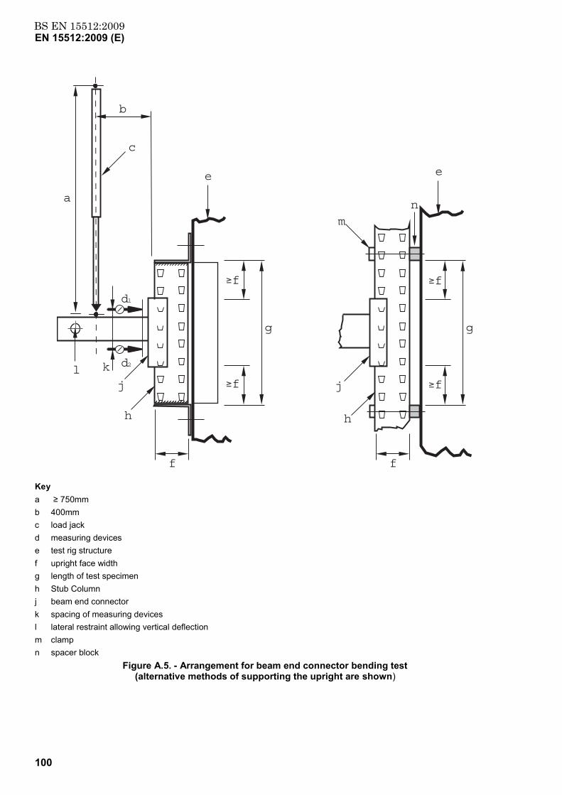
BS EN 15512:2009EN 15512:2009 (E)
100
h
j
c
b
f
g
h
f
f
g
m
k
f
j
a
e
l
e
d1
d2
f
f
n
Key a ≥ 750mm b 400mm c load jack d measuring devices e test rig structure f upright face width g length of test specimen h Stub Column j beam end connector k spacing of measuring devices l lateral restraint allowing vertical deflection m clamp n spacer block
Figure A.5. - Arrangement for beam end connector bending test (alternative methods of supporting the upright are shown)
BS EN 15512:2009EN 15512:2009 (E)
101
A.2.4.3 Test Procedure
The tests described in Figure A.5 load the connector vertically downwards. Separate values for the stiffness and strength shall be obtained for both right and left hand connectors and the mean value used in design.
An initial load, F, equal to 10 % of the anticipated failure load may be applied to the assembly and then removed as a preload in order to bed in the components. The gauges should then be reset. The load, F, shall then be increased gradually until the maximum load is reached and the connection fails. The rotation of the connection shall be observed and, for each test, a plot of the moment M and the rotation θ shall be made, in which:
M= a F (A.7)
and
θ = d - 12 δδ (A.8)
where
a = lever arm for the load F;
d = distance between the gauges C1 and C2 as shown in Figure A.5;
δ1 = deflection measured by gauge C1;
δ 2 = deflection measured by gauge C2.
A.2.4.4 Corrections to the observations
The yield stress and thickness of the materials of the beam, upright and connector shall be determined and the correction factor Cm calculated where
Cm = ((fy / ft)α (t / tt))max but Cm ≤ 1.0 (A.9)
where
ft = the observed yield stress for the relevant component;
fy = the nominal yield stress for the relevant component;
tt = the observed thickness for the relevant component;
t = the design thickness for the relevant component;
α = 0 when fy ≥ ft;
α = 1,0 when fy < ft.
Unless the beam fails or the beam yield strength is more than 1,25 times the guaranteed strength, the relevant component is either the beam end connector or the upright end of the two, the one that gives the largest correction to the test values irrespective of which component was observed to fail shall be used. If the beam fails, the correction relating to beam materials shall also be taken into account. Corrections of 15% and below may be ignored.
BS EN 15512:2009EN 15512:2009 (E)
102
In order to make corrections to the observations, the moment rotation (Mt-θ) curve for each test shall be separated into two components, one to represent the elastic deformations and the other the inelastic deformations of the connection.
The procedure shall be as follows.
a) Plot the unadjusted test results as moment rotation curve (Mt-θt).
b) Measure the slope of this curve,(k0) at the origin.
c) From the observed rotations, θt, subtract the elastic rotations Mt/k0 to obtain the plastic rotations θp.
d) Calculate the corrected moments Mn, where Mn = Mt×C. Where C = 0,15 + Cm and C is less than or equal to 1,0.
e) Add back the elastic rotations, now Mn/k0, to give new rotations θn= θp+ Mn/k0.
f) Plot the adjusted moment rotation curve (Mn- θn).
NOTE 1 The adjusted moment rotation curve has the same initial slope, k0 as the original observed curve.
NOTE 2 An algebraic expression may be used to represent the plotted curve of the moment as a function of the rotation. This expression should not have more than 5 independent coefficients. This may be achieved by using a least squares curve fitting process.
A.2.4.5 Derivation of the Results and Procedure to define curves
A.2.4.5.1 General
The failure moment, Mni, shall be taken to be the maximum corrected moment, as indicated in Figure A.6.
For each upright and connector assembly, the characteristic failure moment Mk shall be calculated in accordance with 13.3.3. The design moment for the connection is then MRd, where:
MRd = γ
ηM
kM (A.10)
where
γ M = partial safety factor for connections, defined in 7.5.
η = variable moment reduction factor selected by the designer ≤ 1
NOTE Any value of the design moment may be chosen less than or equal to the allowable maximum in order to optimise the possibly conflicting requirements for stiffness and strength. Thus, by reducing the design strength a greater design stiffness may be achieved.
A.2.4.5.2 Procedure to derive a bi-linear curve.
A bi-linear moment rotation relationship consists of a linear rotational stiffness together with a design strength chosen as described by Equation (A.10).
The rotational stiffness of the connector shall be obtained as the slope kni of a line through the origin which isolates equal areas between it and the experimental curve, below the design moment corrected for yield and thickness, MRdc, as shown in Figure A.6, provided that:
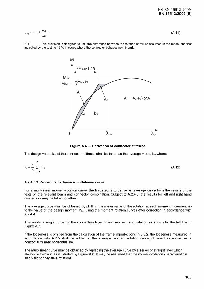
BS EN 15512:2009EN 15512:2009 (E)
103
M 1,15 k
kii
θRd
n ≤ (A.11)
NOTE This provision is designed to limit the difference between the rotation at failure assumed in the model and that indicated by the test, to 15 % in cases where the connector behaves non-linearly.
A1 = A2 +/- 5%
Mk,i/ M
θ Rd,i/1.15
θ Rd,i θ n,i
Mk,i
MRd,i
Mi
A1
kni
A2
0
Figure A.6 — Derivation of connector stiffness
The design value, kd, of the connector stiffness shall be taken as the average value, km where:
km= k 1=i
n
n1
in∑ (A.12)
A.2.4.5.3 Procedure to derive a multi-linear curve
For a multi-linear moment-rotation curve, the first step is to derive an average curve from the results of the tests on the relevant beam and connector combination. Subject to A.2.4.3, the results for left and right hand connectors may be taken together.
The average curve shall be obtained by plotting the mean value of the rotation at each moment increment up to the value of the design moment MRd using the moment rotation curves after correction in accordance with A.2.4.4.
This yields a single curve for the connection type, linking moment and rotation as shown by the full line in Figure A.7.
If the looseness is omitted from the calculation of the frame imperfections in 5.3.2, the looseness measured in accordance with A.2.5 shall be added to the average moment rotation curve, obtained as above, as a horizontal or near horizontal line.
The multi-linear curve may be obtained by replacing the average curve by a series of straight lines which always lie below it, as illustrated by Figure A.8. It may be assumed that the moment-rotation characteristic is also valid for negative rotations.
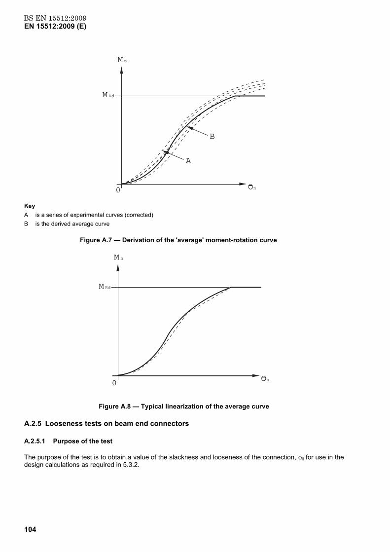
BS EN 15512:2009EN 15512:2009 (E)
104
A
B
M n
M Rd
n0 O
Key A is a series of experimental curves (corrected) B is the derived average curve
Figure A.7 — Derivation of the 'average' moment-rotation curve
M n
M Rd
0 nO
Figure A.8 — Typical linearization of the average curve
A.2.5 Looseness tests on beam end connectors
A.2.5.1 Purpose of the test
The purpose of the test is to obtain a value of the slackness and looseness of the connection, φli for use in the design calculations as required in 5.3.2.
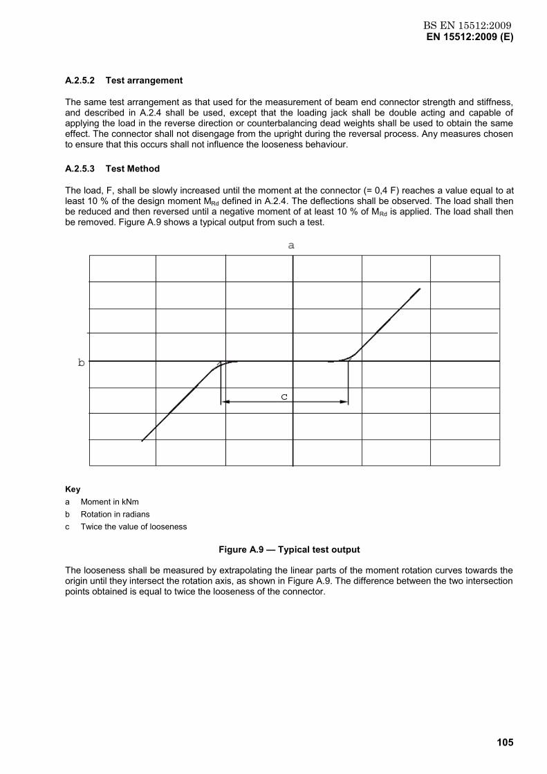
BS EN 15512:2009EN 15512:2009 (E)
105
A.2.5.2 Test arrangement
The same test arrangement as that used for the measurement of beam end connector strength and stiffness, and described in A.2.4 shall be used, except that the loading jack shall be double acting and capable of applying the load in the reverse direction or counterbalancing dead weights shall be used to obtain the same effect. The connector shall not disengage from the upright during the reversal process. Any measures chosen to ensure that this occurs shall not influence the looseness behaviour.
A.2.5.3 Test Method
The load, F, shall be slowly increased until the moment at the connector (= 0,4 F) reaches a value equal to at least 10 % of the design moment MRd defined in A.2.4. The deflections shall be observed. The load shall then be reduced and then reversed until a negative moment of at least 10 % of MRd is applied. The load shall then be removed. Figure A.9 shows a typical output from such a test.
Key a Moment in kNm b Rotation in radians c Twice the value of looseness
Figure A.9 — Typical test output
The looseness shall be measured by extrapolating the linear parts of the moment rotation curves towards the origin until they intersect the rotation axis, as shown in Figure A.9. The difference between the two intersection points obtained is equal to twice the looseness of the connector.
BS EN 15512:2009EN 15512:2009 (E)
106
A.2.5.4 Corrections to the observations
Corrections need not be made to the observations to account for thickness or strength variations.
A.2.5.5 Derivation of results
The looseness shall be taken to be the mean value φl of at least three test results φli.
A.2.6 Shear tests on beam end connectors and connector locks
A.2.6.1 Purpose of the test
The purpose of the test is to measure the shear strength of the connector or of the connector lock. All combinations specified in A.2.4.1 shall be tested.
A.2.6.2 Test arrangement
The test arrangement comprises a short length of upright connected rigidly to a relatively infinitely stiff frame, with a length of beam section attached to it by means of the connection to be tested, as shown in Figure A.10. The load shall be applied to the connection by a pin-ended jack, placed a distance ‘a’ from the face of the upright and as close to it as possible. The free end of the beam shall be restrained by a pinned support at least 400 mm from the face of the upright, as shown in Figure A.10. This support shall be adjusted in the vertical direction so that the beam remains horizontal during the test.
To test the connector lock, the test piece shall be installed in the inverted position and, in addition to the loading shown in Figure A.10, a constant load of 500 N shall be applied to the top surface of the beam in a direction normal to the face of the upright, such as to pull the beam end connector away from the face of the upright.
NOTE The purpose of this force is to take away horizontal freedom of movement in the assembly and to thereby create the worst condition for the connector lock.
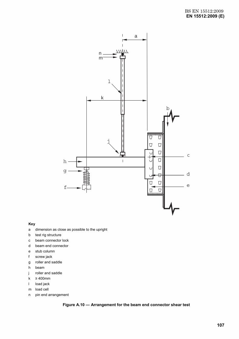
BS EN 15512:2009EN 15512:2009 (E)
107
a
nm
g
k
d
e
c
f
b
j
l
h
Key a dimension as close as possible to the upright b test rig structure c beam connector lock d beam end connector e stub column f screw jack g roller and saddle h beam j roller and saddle k ≥ 400mm l load jack m load cell n pin end arrangement
Figure A.10 — Arrangement for the beam end connector shear test
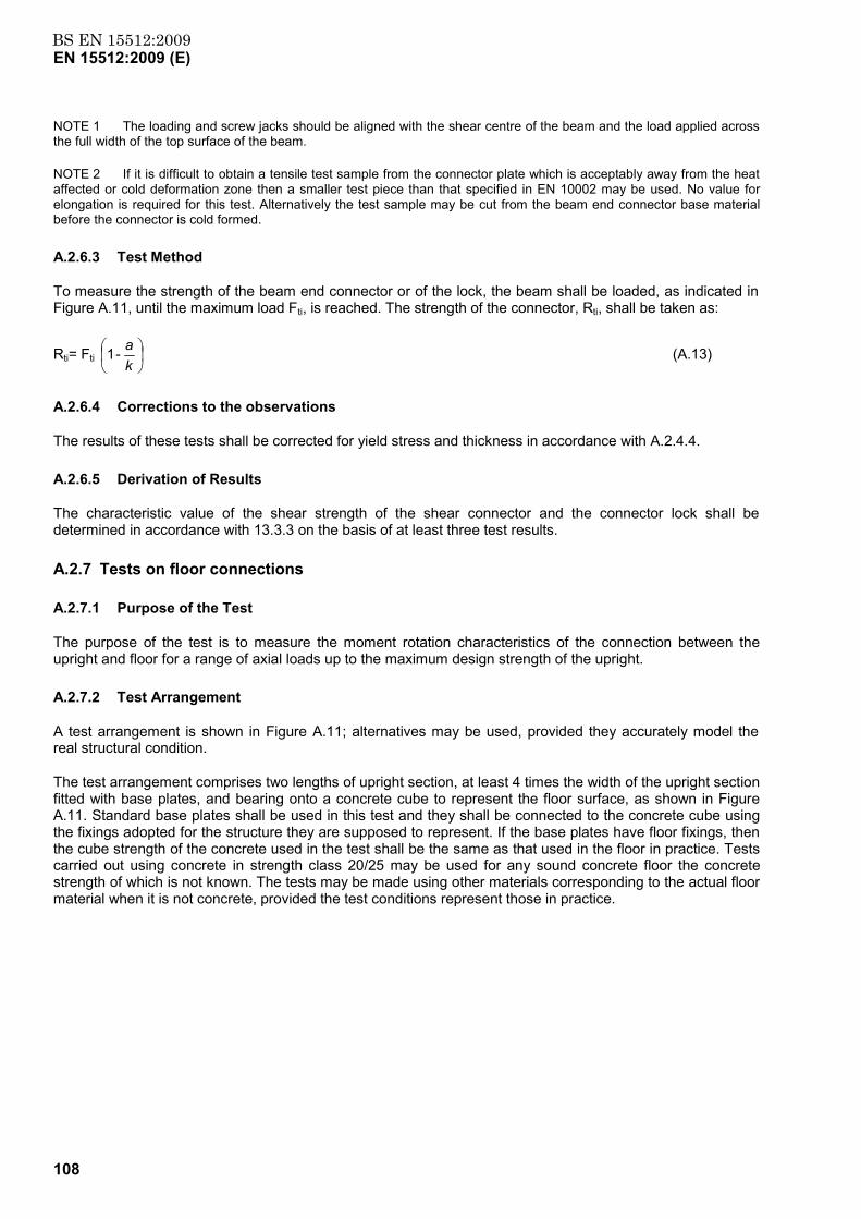
BS EN 15512:2009EN 15512:2009 (E)
108
NOTE 1 The loading and screw jacks should be aligned with the shear centre of the beam and the load applied across the full width of the top surface of the beam.
NOTE 2 If it is difficult to obtain a tensile test sample from the connector plate which is acceptably away from the heat affected or cold deformation zone then a smaller test piece than that specified in EN 10002 may be used. No value for elongation is required for this test. Alternatively the test sample may be cut from the beam end connector base material before the connector is cold formed.
A.2.6.3 Test Method
To measure the strength of the beam end connector or of the lock, the beam shall be loaded, as indicated in Figure A.11, until the maximum load Fti, is reached. The strength of the connector, Rti, shall be taken as:
Rti= Fti
ka - 1 (A.13)
A.2.6.4 Corrections to the observations
The results of these tests shall be corrected for yield stress and thickness in accordance with A.2.4.4.
A.2.6.5 Derivation of Results
The characteristic value of the shear strength of the shear connector and the connector lock shall be determined in accordance with 13.3.3 on the basis of at least three test results.
A.2.7 Tests on floor connections
A.2.7.1 Purpose of the Test
The purpose of the test is to measure the moment rotation characteristics of the connection between the upright and floor for a range of axial loads up to the maximum design strength of the upright.
A.2.7.2 Test Arrangement
A test arrangement is shown in Figure A.11; alternatives may be used, provided they accurately model the real structural condition.
The test arrangement comprises two lengths of upright section, at least 4 times the width of the upright section fitted with base plates, and bearing onto a concrete cube to represent the floor surface, as shown in Figure A.11. Standard base plates shall be used in this test and they shall be connected to the concrete cube using the fixings adopted for the structure they are supposed to represent. If the base plates have floor fixings, then the cube strength of the concrete used in the test shall be the same as that used in the floor in practice. Tests carried out using concrete in strength class 20/25 may be used for any sound concrete floor the concrete strength of which is not known. The tests may be made using other materials corresponding to the actual floor material when it is not concrete, provided the test conditions represent those in practice.
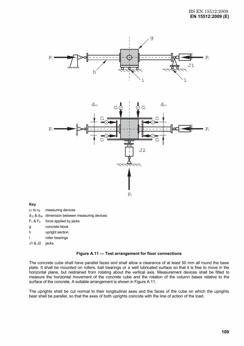
BS EN 15512:2009EN 15512:2009 (E)
109
F1
F1
F1
F1
h
g
i i
J1
C5
C4
C3
C1
d12
C2
F2
J2
C6d34
Key c1 to c6 measuring devices d12 & d34 dimension between measuring devices F1 & F2 force applied by jacks g concrete block h upright section i roller bearings J1 & J2 jacks
Figure A.11 — Test arrangement for floor connections
The concrete cube shall have parallel faces and shall allow a clearance of at least 50 mm all round the base plate. It shall be mounted on rollers, ball bearings or a well lubricated surface so that it is free to move in the horizontal plane, but restrained from rotating about the vertical axis. Measurement devices shall be fitted to measure the horizontal movement of the concrete cube and the rotation of the column bases relative to the surface of the concrete. A suitable arrangement is shown in Figure A.11.
The uprights shall be cut normal to their longitudinal axes and the faces of the cube on which the uprights bear shall be parallel, so that the axes of both uprights coincide with the line of action of the load.
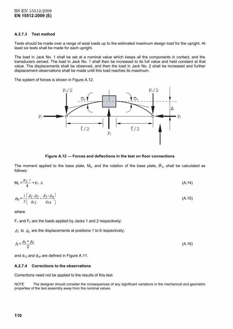
BS EN 15512:2009EN 15512:2009 (E)
110
A.2.7.3 Test method
Tests should be made over a range of axial loads up to the estimated maximum design load for the upright. At least six tests shall be made for each upright.
The load in Jack No. 1 shall be set at a nominal value which keeps all the components in contact, and the transducers zeroed. The load in Jack No. 1 shall then be increased to its full value and held constant at that value. The displacements shall be observed, and then the load in Jack No. 2 shall be increased and further displacement observations shall be made until this load reaches its maximum.
The system of forces is shown in Figure A.12.
F1 F1
F2/2 F2/2
F2/2/2
ObOb
Figure A.12 — Forces and deflections in the test on floor connections
The moment applied to the base plate, Mb, and the rotation of the base plate, θ b, shall be calculated as follows:
Mb = ∆ F + 4 F
12 l (A.14)
θ b =
d-
+ d-
21
34
43
12
21 δδδδ (A.15)
where
F1 and F2 are the loads applied by Jacks 1 and 2 respectively;
δ1 to δ 6 are the displacements at positions 1 to 6 respectively;
∆ =2 + 65 δδ (A.16)
and d12 and d34 are defined in Figure A.11.
A.2.7.4 Corrections to the observations
Corrections need not be applied to the results of this test.
NOTE The designer should consider the consequences of any significant variations in the mechanical and geometric properties of the test assembly away from the nominal values.
BS EN 15512:2009EN 15512:2009 (E)
111
A.2.7.5 Derivation of the Results
For a given axial load the design values of the ultimate moment of resistance and the stiffness of the base plate connection shall be calculated in the manner indicated in A.2.4.5 for beam end connectors, for each value of the axial load. The test results shall be plotted on charts of resistance and stiffness versus axial load and, in each case, a smooth design curve or series of straight lines shall be drawn which lie below all the test results. As an alternative a single stiffness may be chosen for all values of the axial load and the corresponding resistances calculated in accordance with A.2.4.5.
A.2.8 Tests for the shear stiffness of upright frames
A.2.8.1 Purpose of the tests
The purpose of the tests is to determine the transverse shear stiffness per unit length of the frame structure in order to be able to assess its stability and to assess the shear strength of the frame.
A.2.8.2 Test Arrangement
The test sample shall be a frame assembly with a number of bracing panels loaded in the manner shown in Figure A.13.
At least two panels should be used, as shown in Figures A.13.
One leg of the frame shall be pinned at one end so that it is prevented from moving horizontally, as at point X in Figure A.13, and the load applied along the centroid of the other leg, at point Y in Figure A.13.
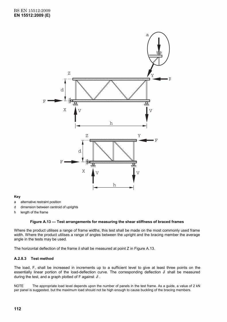
BS EN 15512:2009EN 15512:2009 (E)
112
h
F
VV
V V
d
YZ
YZ
X
X
F
h
d
a
F
F
Key a alternative restraint position d dimension between centroid of uprights h length of the frame
Figure A.13 — Test arrangements for measuring the shear stiffness of braced frames
Where the product utilises a range of frame widths, this test shall be made on the most commonly used frame width. Where the product utilises a range of angles between the upright and the bracing member the average angle in the tests may be used.
The horizontal deflection of the frame δ shall be measured at point Z in Figure A.13.
A.2.8.3 Test method
The load, F, shall be increased in increments up to a sufficient level to give at least three points on the essentially linear portion of the load-deflection curve. The corresponding deflection δ shall be measured during the test, and a graph plotted of F against δ .
NOTE The appropriate load level depends upon the number of panels in the test frame. As a guide, a value of 2 kN per panel is suggested, but the maximum load should not be high enough to cause buckling of the bracing members.
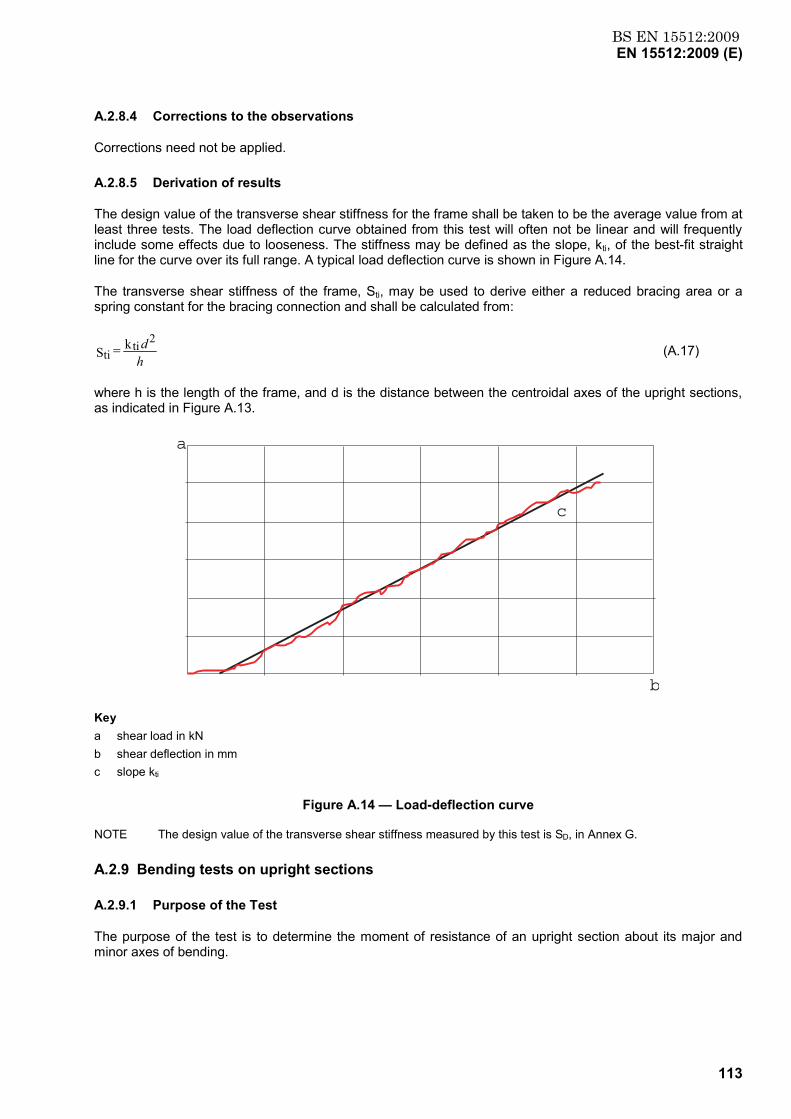
BS EN 15512:2009EN 15512:2009 (E)
113
A.2.8.4 Corrections to the observations
Corrections need not be applied.
A.2.8.5 Derivation of results
The design value of the transverse shear stiffness for the frame shall be taken to be the average value from at least three tests. The load deflection curve obtained from this test will often not be linear and will frequently include some effects due to looseness. The stiffness may be defined as the slope, kti, of the best-fit straight line for the curve over its full range. A typical load deflection curve is shown in Figure A.14.
The transverse shear stiffness of the frame, Sti, may be used to derive either a reduced bracing area or a spring constant for the bracing connection and shall be calculated from:
hd 2ti
tik = S (A.17)
where h is the length of the frame, and d is the distance between the centroidal axes of the upright sections, as indicated in Figure A.13.
a
b
c
Key a shear load in kN b shear deflection in mm c slope kti
Figure A.14 — Load-deflection curve
NOTE The design value of the transverse shear stiffness measured by this test is SD, in Annex G.
A.2.9 Bending tests on upright sections
A.2.9.1 Purpose of the Test
The purpose of the test is to determine the moment of resistance of an upright section about its major and minor axes of bending.
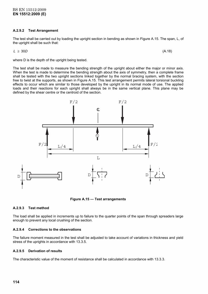
BS EN 15512:2009EN 15512:2009 (E)
114
A.2.9.2 Test Arrangement
The test shall be carried out by loading the upright section in bending as shown in Figure A.15. The span, L, of the upright shall be such that:
DL 03 ≥ (A.18)
where D is the depth of the upright being tested.
The test shall be made to measure the bending strength of the upright about either the major or minor axis. When the test is made to determine the bending strength about the axis of symmetry, then a complete frame shall be tested with the two upright sections linked together by the normal bracing system, with the section free to twist at the supports, as shown in Figure A.15. This test arrangement permits lateral torsional buckling effects to occur which are similar to those developed by the upright in its normal mode of use. The applied loads and their reactions for each upright shall always be in the same vertical plane. This plane may be defined by the shear centre or the centroid of the section.
CL
F/2
F/2 F/2L/4L/4
L
F/2
D
D
D
Figure A.15 — Test arrangements
A.2.9.3 Test method
The load shall be applied in increments up to failure to the quarter points of the span through spreaders large enough to prevent any local crushing of the section.
A.2.9.4 Corrections to the observations
The failure moment measured in the test shall be adjusted to take account of variations in thickness and yield stress of the uprights in accordance with 13.3.5.
A.2.9.5 Derivation of results
The characteristic value of the moment of resistance shall be calculated in accordance with 13.3.3.
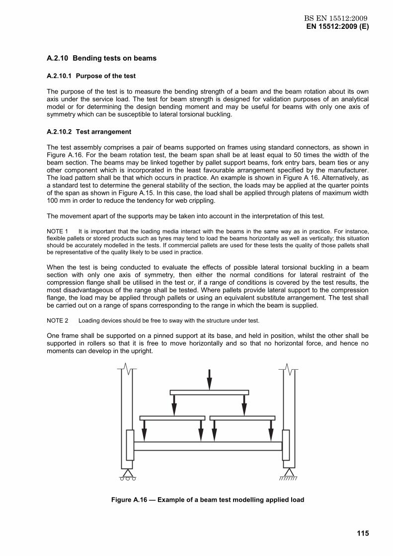
BS EN 15512:2009EN 15512:2009 (E)
115
A.2.10 Bending tests on beams
A.2.10.1 Purpose of the test
The purpose of the test is to measure the bending strength of a beam and the beam rotation about its own axis under the service load. The test for beam strength is designed for validation purposes of an analytical model or for determining the design bending moment and may be useful for beams with only one axis of symmetry which can be susceptible to lateral torsional buckling.
A.2.10.2 Test arrangement
The test assembly comprises a pair of beams supported on frames using standard connectors, as shown in Figure A.16. For the beam rotation test, the beam span shall be at least equal to 50 times the width of the beam section. The beams may be linked together by pallet support beams, fork entry bars, beam ties or any other component which is incorporated in the least favourable arrangement specified by the manufacturer. The load pattern shall be that which occurs in practice. An example is shown in Figure A 16. Alternatively, as a standard test to determine the general stability of the section, the loads may be applied at the quarter points of the span as shown in Figure A.15. In this case, the load shall be applied through platens of maximum width 100 mm in order to reduce the tendency for web crippling.
The movement apart of the supports may be taken into account in the interpretation of this test.
NOTE 1 It is important that the loading media interact with the beams in the same way as in practice. For instance, flexible pallets or stored products such as tyres may tend to load the beams horizontally as well as vertically; this situation should be accurately modelled in the tests. If commercial pallets are used for these tests the quality of those pallets shall be representative of the quality likely to be used in practice.
When the test is being conducted to evaluate the effects of possible lateral torsional buckling in a beam section with only one axis of symmetry, then either the normal conditions for lateral restraint of the compression flange shall be utilised in the test or, if a range of conditions is covered by the test results, the most disadvantageous of the range shall be tested. Where pallets provide lateral support to the compression flange, the load may be applied through pallets or using an equivalent substitute arrangement. The test shall be carried out on a range of spans corresponding to the range in which the beam is supplied.
NOTE 2 Loading devices should be free to sway with the structure under test.
One frame shall be supported on a pinned support at its base, and held in position, whilst the other shall be supported in rollers so that it is free to move horizontally and so that no horizontal force, and hence no moments can develop in the upright.
Figure A.16 — Example of a beam test modelling applied load
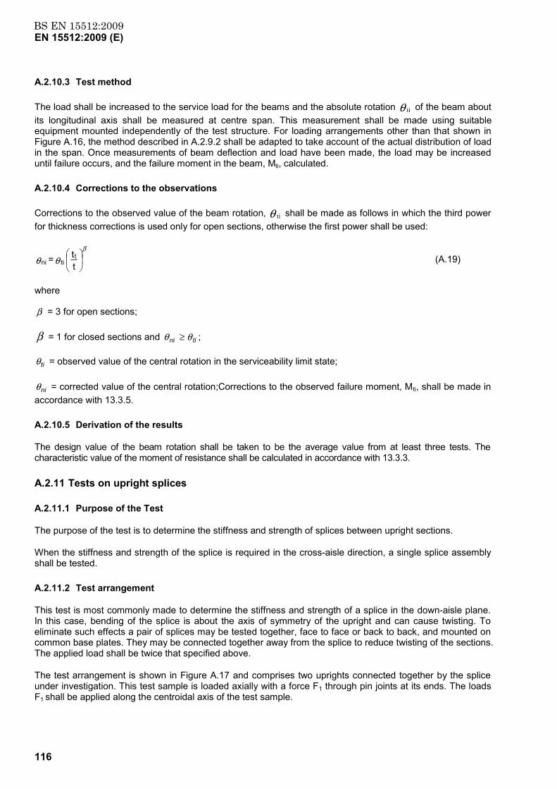
BS EN 15512:2009EN 15512:2009 (E)
116
A.2.10.3 Test method
The load shall be increased to the service load for the beams and the absolute rotation θ ti of the beam about its longitudinal axis shall be measured at centre span. This measurement shall be made using suitable equipment mounted independently of the test structure. For loading arrangements other than that shown in Figure A.16, the method described in A.2.9.2 shall be adapted to take account of the actual distribution of load in the span. Once measurements of beam deflection and load have been made, the load may be increased until failure occurs, and the failure moment in the beam, Mti, calculated.
A.2.10.4 Corrections to the observations
Corrections to the observed value of the beam rotation, θ ti shall be made as follows in which the third power for thickness corrections is used only for open sections, otherwise the first power shall be used:
tt = t
tini
β
θθ (A.19)
where
β = 3 for open sections;
β = 1 for closed sections and tini θθ ≥ ;
tiθ = observed value of the central rotation in the serviceability limit state;
niθ = corrected value of the central rotation;Corrections to the observed failure moment, Mti, shall be made in accordance with 13.3.5.
A.2.10.5 Derivation of the results
The design value of the beam rotation shall be taken to be the average value from at least three tests. The characteristic value of the moment of resistance shall be calculated in accordance with 13.3.3.
A.2.11 Tests on upright splices
A.2.11.1 Purpose of the Test
The purpose of the test is to determine the stiffness and strength of splices between upright sections.
When the stiffness and strength of the splice is required in the cross-aisle direction, a single splice assembly shall be tested.
A.2.11.2 Test arrangement
This test is most commonly made to determine the stiffness and strength of a splice in the down-aisle plane. In this case, bending of the splice is about the axis of symmetry of the upright and can cause twisting. To eliminate such effects a pair of splices may be tested together, face to face or back to back, and mounted on common base plates. They may be connected together away from the splice to reduce twisting of the sections. The applied load shall be twice that specified above.
The test arrangement is shown in Figure A.17 and comprises two uprights connected together by the splice under investigation. This test sample is loaded axially with a force F1 through pin joints at its ends. The loads F1 shall be applied along the centroidal axis of the test sample.
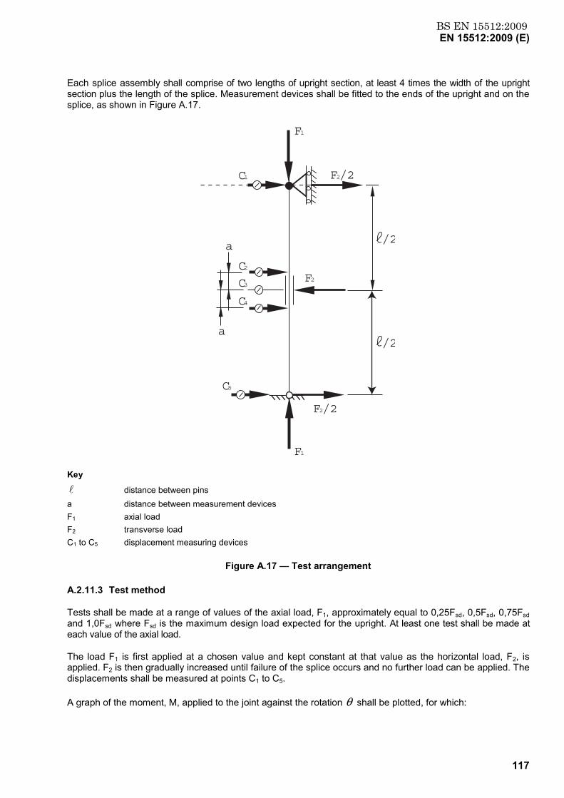
BS EN 15512:2009EN 15512:2009 (E)
117
Each splice assembly shall comprise of two lengths of upright section, at least 4 times the width of the upright section plus the length of the splice. Measurement devices shall be fitted to the ends of the upright and on the splice, as shown in Figure A.17.
a
a
F2/2
F2
C1
C2
C3
C4
C5
F1
F1
F2/2
/2
/2
Key
l distance between pins a distance between measurement devices F1 axial load F2 transverse load C1 to C5 displacement measuring devices
Figure A.17 — Test arrangement
A.2.11.3 Test method
Tests shall be made at a range of values of the axial load, F1, approximately equal to 0,25Fsd, 0,5Fsd, 0,75Fsd and 1,0Fsd where Fsd is the maximum design load expected for the upright. At least one test shall be made at each value of the axial load.
The load F1 is first applied at a chosen value and kept constant at that value as the horizontal load, F2, is applied. F2 is then gradually increased until failure of the splice occurs and no further load can be applied. The displacements shall be measured at points C1 to C5.
A graph of the moment, M, applied to the joint against the rotation θ shall be plotted, for which:
BS EN 15512:2009EN 15512:2009 (E)
118
M=
2 + - F +
4 F 51
312δδδ
l (A.20)
and:
θ =
2 +
- a2 42
3δδ
δ (A.21)
A.2.11.4 Corrections to observations
Corrections need not be applied to the results of this test.
NOTE The designer should consider the consequences of any significant variations in the mechanical and geometric properties of the test assembly away from the nominal values.
A.2.11.5 Derivation of results
The characteristic values for the stiffness and strength of the splice for each value of the axial load F1 shall be derived in the manner described for floor connections in A.2.7.5.
If the variation of stiffness or design ultimate moment with axial force is not greater than ± 10 % of the mean value for the range of axial loads (F1) up to the design load for the upright, the mean value may be assumed and used in the analysis and design of the structure. Where there is greater variation in the failure moment and the stiffness of the splice, then appropriate values corresponding to the design axial force shall be used.

BS EN 15512:2009EN 15512:2009 (E)
119
Annex B (informative)
Amplified sway method for down-aisle stability analysis
B.1 General
The amplified sway method provides a close approximation to the value of the elastic critical load Vcr of a plane frame. It then allows the increase in the bending moments and deflections due to second order effects to be estimated.
The principles are described with reference to Figure B.1.
W W W W
W W W W
W W W W
W W W W
Figure B.1 a) Actual frame and loading
OnbW
hL
U
OnbW
OnbW
OnbW
δ
δ
OnbW
Key ● Semi rigid connection
Figure B.1 b) Imperfection horizontal loads and resulting deflections
Figure B.1 — Basis of the amplified sway method
BS EN 15512:2009EN 15512:2009 (E)
120
B.2 Linear elastic analysis
A linear elastic analysis of the complete frame may be carried out in order to determine the internal forces and deflections due to the imperfection horizontal loads as shown in Figure B.1. These loads are defined in 5.3.2 and Figure 7.
The flexibility of the beam to upright connections may be taken into account.
Allowance may be made for the stiffness of the upright to floor connections (see A.2.7).
B.3 Elastic critical value
The elastic critical value of the vertical load for failure in a sway mode, Vcr, may then be determined as:
φφ
maxSdcr =
VV (B.1)
where
VSd = design value of the vertical load on the frame;
maxφ = largest value of the sway index Sφ of any storey;
φ s (δU - δL)/h
h = storey height;
uδ = horizontal deflection at the top of the storey;
Lδ = horizontal deflection at the bottom of the storey.
B.4 Amplification factor
At the required limit state, the design internal forces and deflections in any sway mode are amplified by the factor β , where:
V - VV =
Sdcr
crβ (B.2)
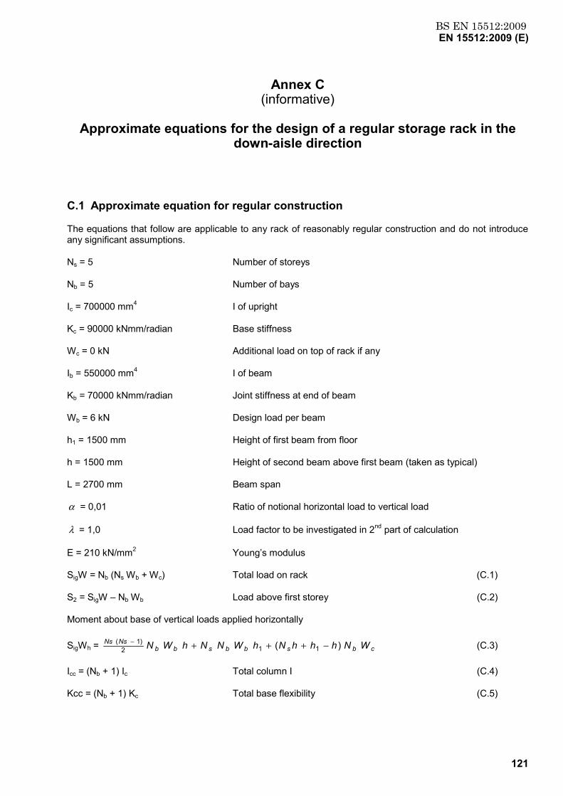
BS EN 15512:2009EN 15512:2009 (E)
121
Annex C (informative)
Approximate equations for the design of a regular storage rack in the
down-aisle direction
C.1 Approximate equation for regular construction
The equations that follow are applicable to any rack of reasonably regular construction and do not introduce any significant assumptions.
Ns = 5 Number of storeys
Nb = 5 Number of bays
Ic = 700000 mm4 I of upright
Kc = 90000 kNmm/radian Base stiffness
Wc = 0 kN Additional load on top of rack if any
Ib = 550000 mm4 I of beam
Kb = 70000 kNmm/radian Joint stiffness at end of beam
Wb = 6 kN Design load per beam
h1 = 1500 mm Height of first beam from floor
h = 1500 mm Height of second beam above first beam (taken as typical)
L = 2700 mm Beam span
α = 0,01 Ratio of notional horizontal load to vertical load
λ = 1,0 Load factor to be investigated in 2nd part of calculation
E = 210 kN/mm2 Young’s modulus
SigW = Nb (Ns Wb + Wc) Total load on rack (C.1)
S2 = SigW – Nb Wb Load above first storey (C.2)
Moment about base of vertical loads applied horizontally
SigWh = cbsbbsbbNsNs WNhhhNhWNNhWN )( 112
)1( −+++− (C.3)
Icc = (Nb + 1) Ic Total column I (C.4)
Kcc = (Nb + 1) Kc Total base flexibility (C.5)
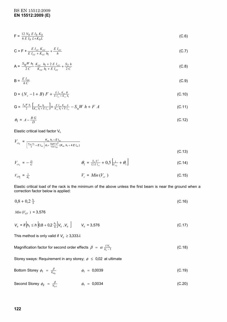
BS EN 15512:2009EN 15512:2009 (E)
122
F = LKLIEKIENbb
bbb+6
12 (C.6)
C = F + hIE
hKIEKIE cc
cccccccc +
+ 1 (C.7)
A = ChS
IEhKIEhK
ChWS
ccccccccig
22
22
111 +
++ (C.8)
B = ChIE cc (C.9)
D = 1
)1( hKIEBKIE
s cccc
ccccFBN +++− (C.10)
G = [ ] AFhWSigIEhKAKIE
IEhKhKhWS
cccc
cccc
cccc
ccig +−+ ++ 11
112 (C.11)
1θ = DGBA − (C.12)
Elastic critical load factor Vc
0crV = )4( 112
21
121
1
ccccccIEhSigW
cchccK
cccc
IEhKIE
IEhK
++
+
+
θ
(C.13)
2crV = GD− 2θ = [ ]1
112 2
22 5,0 θ++
crcc VIEhS (C.14)
1crV = 2
1θ cV = )( crVMin (C.15)
Elastic critical load of the rack is the minimum of the above unless the first beam is near the ground when a correction factor below is applied:
hh12,08,0 + (C.16)
)( crVMin = 3,576
cV = if [ ][ ]cchh VVhh ,2,08,0 1
1 +≤ cV = 3,576 (C.17)
This method is only valid if λ333,3≥cV
Magnification factor for second order effects 1−=c
cV
Vλαβ (C.18)
Storey sways: Requirement in any storey; 02,0≤φ at ultimate
Bottom Storey 0
1crVβφ = 0039,01 =φ (C.19)
Second Storey 1
2crVβφ = 0034,01 =φ (C.20)
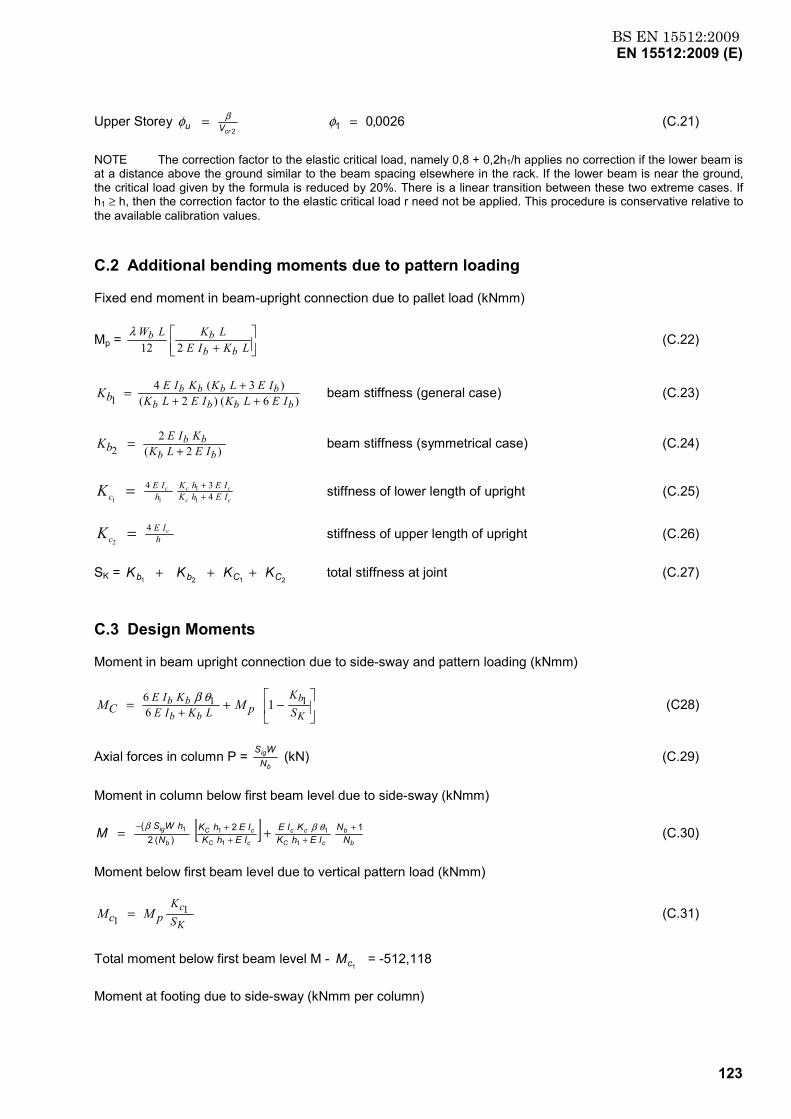
BS EN 15512:2009EN 15512:2009 (E)
123
Upper Storey 2crVu
βφ = 0026,01 =φ (C.21)
NOTE The correction factor to the elastic critical load, namely 0,8 + 0,2h1/h applies no correction if the lower beam is at a distance above the ground similar to the beam spacing elsewhere in the rack. If the lower beam is near the ground, the critical load given by the formula is reduced by 20%. There is a linear transition between these two extreme cases. If h1 ≥ h, then the correction factor to the elastic critical load r need not be applied. This procedure is conservative relative to the available calibration values.
C.2 Additional bending moments due to pattern loading
Fixed end moment in beam-upright connection due to pallet load (kNmm)
Mp =
+ LKIELKLW
bbbb
212λ (C.22)
)6()2()3(4
1 bbbbbbbb
IELKIELKIELKKIE
bK +++= beam stiffness (general case) (C.23)
)2(2
2 bbbbIELK
KIEbK += beam stiffness (symmetrical case) (C.24)
cc
cccIEhKIEhK
hIE
cK 434
1
1
11 ++= stiffness of lower length of upright (C.25)
hIE
ccK 4
2= stiffness of upper length of upright (C.26)
SK = 2121 CCbb KKKK +++ total stiffness at joint (C.27)
C.3 Design Moments
Moment in beam upright connection due to side-sway and pattern loading (kNmm)
−+= + K
b
bbbb
SK
pLKIEKIE
C MM 11 166 θβ (C28)
Axial forces in column P = b
ig
NWS (kN) (C.29)
Moment in column below first beam level due to side-sway (kNmm)
[ ]b
b
cC
cc
cC
cC
b
ig
NN
IEhKKIE
IEhKIEhK
NhWSM 12
)(2(
1
1
1
11 +++
+− += θββ (C.30)
Moment below first beam level due to vertical pattern load (kNmm)
K
cSK
pc MM 11 = (C.31)
Total moment below first beam level M - 1cM = -512,118
Moment at footing due to side-sway (kNmm per column)
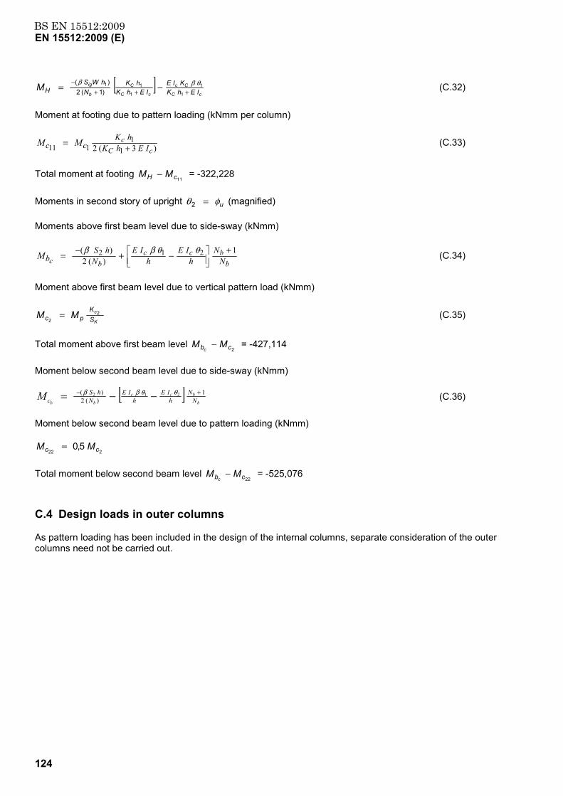
BS EN 15512:2009EN 15512:2009 (E)
124
[ ]cC
Cc
cC
C
b
ig
IEhKKIE
IEhKhK
NhWS
HM +++− −=
1
1
1
11
)1(2)( θββ (C.32)
Moment at footing due to pattern loading (kNmm per column)
)3(2 11
111 cCc
IEhKhK
cc MM += (C.33)
Total moment at footing 11cH MM − = -322,228
Moments in second story of upright uφθ =2 (magnified)
Moments above first beam level due to side-sway (kNmm)
bbcc
bc NN
hIE
hIE
NhS
bM 1)(2
)( 212 +−
−+= θθββ (C.34)
Moment above first beam level due to vertical pattern load (kNmm)
K
c
SK
pc MM 22
= (C.35)
Total moment above first beam level 2cb MM
c− = -427,114
Moment below second beam level due to side-sway (kNmm)
[ ]b
bcc
bb NN
hIE
hIE
NhS
cM 1)(2
)( 212 +− −−= θθββ (C.36)
Moment below second beam level due to pattern loading (kNmm)
2225,0 cc MM =
Total moment below second beam level 22cb MM
c− = -525,076
C.4 Design loads in outer columns
As pattern loading has been included in the design of the internal columns, separate consideration of the outer columns need not be carried out.
BS EN 15512:2009EN 15512:2009 (E)
125
Annex D (informative)
Background to the acceptance of materials of low fu/fy ratio (cold
reduced steel)
In the process of cold reduction, standard steel strip is cold reduced in order to attain improved strength. The characteristic values for fy and fu are then determined and administered under a quality control system to ensure consistent tensile and physical properties. This particular steel can be made to very tight thickness tolerances (better than half that for hot rolled materials) as well as giving benefit on the improved strength attained. Cold reduced materials have been used in the manufacture of pallet racking for in excess of forty years.
The origin of the requirements in Clause 3.1.1 of EN 1993-1-3:2006 that, for non-standard steels, the ratio fu/fy should be not less than 1,10 is uncertain and probably historical (it has in recent years been reduced from 1,20). Steels permitted in Table 3.1 of EN 1993-1-3:2006 have values as low as 1,09. The corresponding value in the American (AISI) Standard is 1,08 together with an elongation requirement. Certain European manufacturers of racking have many years of experience of using cold reduced steel with fu/fy < 1,10 and, for this reason, a less stringent limit is specified here. The justification for this is threefold.
a) The argument for retaining the 1,10 requirement is difficult to sustain in the light of the above.
b) Difficulties arising as a result of low ductility are very rare and when they do arise they are either in the cold-forming process or in the performance of the connections. In this document, any potential problems in the cold-forming process are eliminated by requiring a bend test. By far the most significant connection in a pallet racking system is the beam to column connection. Testing of this connection is required under this document.
c) The manufacturers who use cold-reduced steel have sponsored an extensive research programme in order to demonstrate that the performance of their products is in no way inferior to that of standard steel.
However, care should be exercised when using such hard material when t > 3 mm or in cold conditions. Thicker material will usually fail the bend test described in Annex A.1.2.
NOTE See Bibliography reference paper J M Davies and J S Cowen, 12th International Speciality Conference.
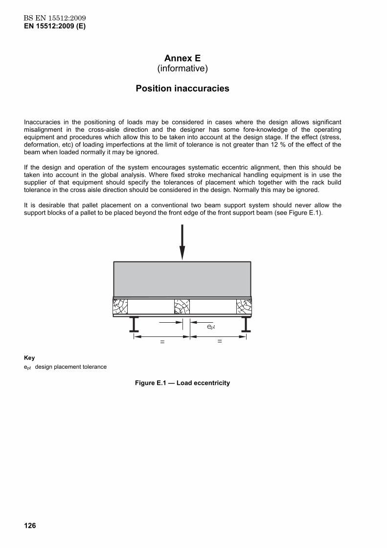
BS EN 15512:2009EN 15512:2009 (E)
126
Annex E (informative)
Position inaccuracies
Inaccuracies in the positioning of loads may be considered in cases where the design allows significant misalignment in the cross-aisle direction and the designer has some fore-knowledge of the operating equipment and procedures which allow this to be taken into account at the design stage. If the effect (stress, deformation, etc) of loading imperfections at the limit of tolerance is not greater than 12 % of the effect of the beam when loaded normally it may be ignored.
If the design and operation of the system encourages systematic eccentric alignment, then this should be taken into account in the global analysis. Where fixed stroke mechanical handling equipment is in use the supplier of that equipment should specify the tolerances of placement which together with the rack build tolerance in the cross aisle direction should be considered in the design. Normally this may be ignored.
It is desirable that pallet placement on a conventional two beam support system should never allow the support blocks of a pallet to be placed beyond the front edge of the front support beam (see Figure E.1).
= =
ep
Key epℓ design placement tolerance
Figure E.1 — Load eccentricity
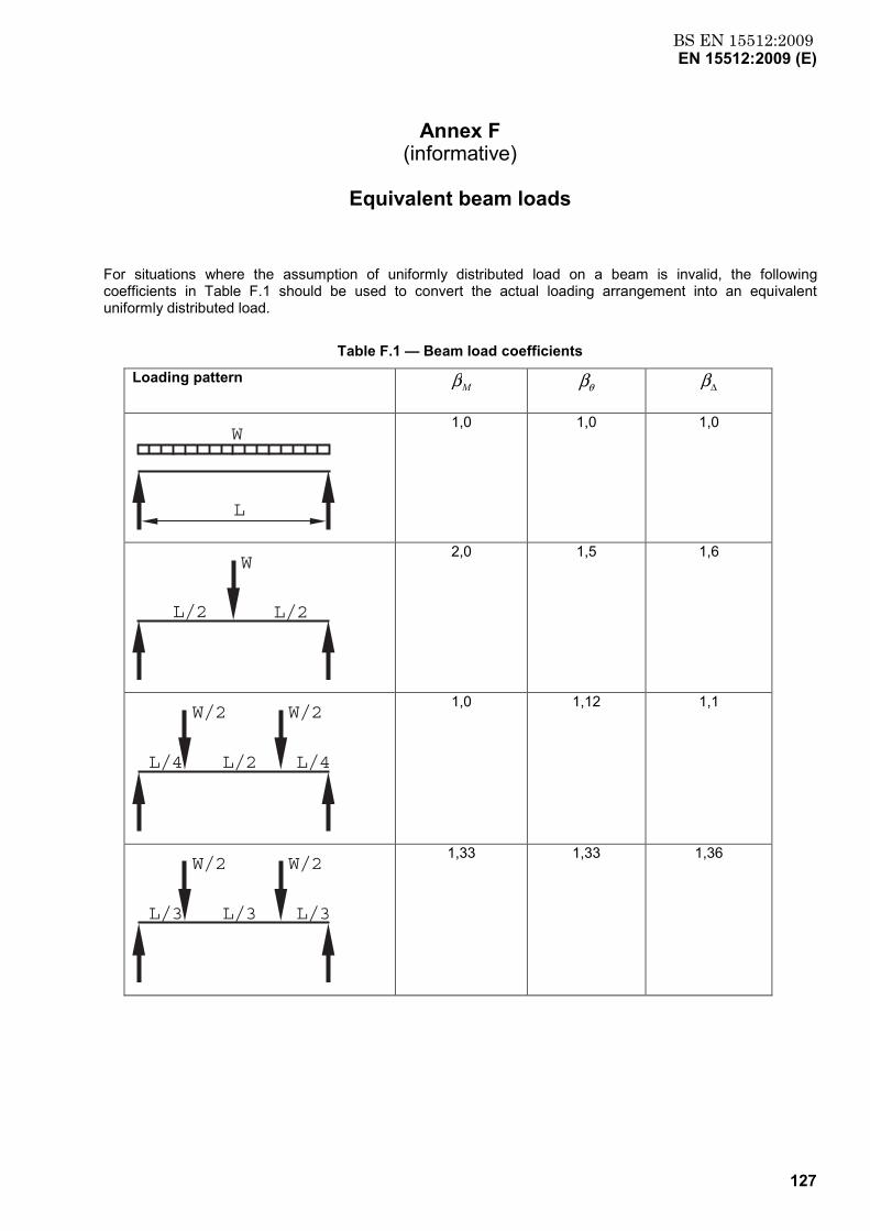
BS EN 15512:2009EN 15512:2009 (E)
127
Annex F (informative)
Equivalent beam loads
For situations where the assumption of uniformly distributed load on a beam is invalid, the following coefficients in Table F.1 should be used to convert the actual loading arrangement into an equivalent uniformly distributed load.
Table F.1 — Beam load coefficients
Loading pattern Mβ θβ ∆β
W
L
1,0 1,0 1,0
L/2 L/2
W
2,0 1,5 1,6
L/4 L/4L/2
W/2 W/2
1,0 1,12 1,1
L/3 L/3L/3
W/2 W/2
1,33 1,33 1,36
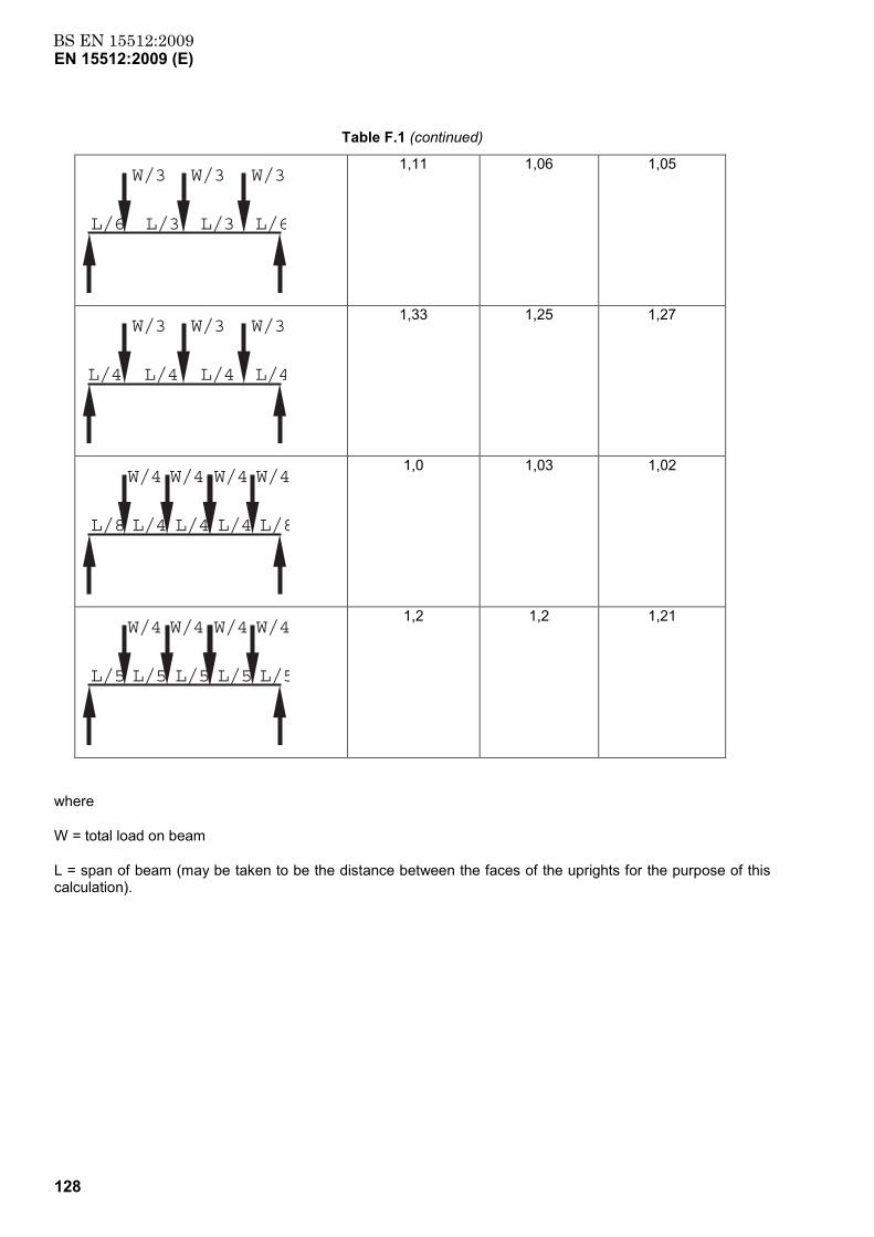
BS EN 15512:2009EN 15512:2009 (E)
128
Table F.1 (continued)
L/6 L/6L/3 L/3
W/3 W/3 W/3
1,11 1,06 1,05
L/4 L/4L/4 L/4
W/3 W/3 W/3
1,33 1,25 1,27
L/8 L/8L/4
W/4 W/4
L/4
W/4 W/4
L/4
1,0 1,03 1,02
L/5 L/5L/5
W/4 W/4
L/5
W/4 W/4
L/5
1,2 1,2 1,21
where
W = total load on beam
L = span of beam (may be taken to be the distance between the faces of the uprights for the purpose of this calculation).
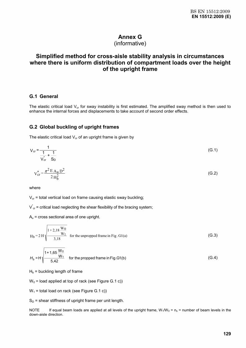
BS EN 15512:2009EN 15512:2009 (E)
129
Annex G (informative)
Simplified method for cross-aisle stability analysis in circumstances
where there is uniform distribution of compartment loads over the height of the upright frame
G.1 General
The elastic critical load Vcr for sway instability is first estimated. The amplified sway method is then used to enhance the internal forces and displacements to take account of second order effects.
G.2 Global buckling of upright frames
The elastic critical load Vcr of an upright frame is given by
S1 +
V1
1 = V
D*cr
cr (G.1)
H 2D A E = V 2
b
2u2*cr
π (G.2)
where
Vcr = total vertical load on frame causing elastic sway buckling;
V*cr = critical load neglecting the shear flexibility of the bracing system;
Au = cross sectional area of one upright.
1(a)G .Figin frame unpropped for the 3,18
WW2,18 + 1
H 2 = H 10
b (G.3)
1(b)G.Fig in frame propped the for 5,42
WW1,65 + 1
H = 1
0
bH (G.4)
Hb = buckling length of frame
W0 = load applied at top of rack (see Figure G.1 c))
W1 = total load on rack (see Figure G.1 c))
SD = shear stiffness of upright frame per unit length.
NOTE If equal beam loads are applied at all levels of the upright frame, W1/W0 = ns = number of beam levels in the down-aisle direction.
BS EN 15512:2009EN 15512:2009 (E)
130
G.3 Shear stiffness of upright frame
For a frame in which the joint flexibility can be shown to be negligible or may be allowed for within the given expressions (e.g. by using a reduced cross-sectional area for the bracing members), the shear stiffness per unit length SD is given by:
S1D
=S1 +
S1 +
S1
dbdddh (G.5)
where expressions for Sdh, Sdd and Sdb are given in Figure G.2 for a variety of different bracing systems.
When a reliable calculation of the shear stiffness cannot be carried out, it should be determined by test in accordance with A.2.8.
G.4 Amplification factor β
If VSd/Vcr < 0,1, global second-order effects may be neglected.
At the limit state, the sway component of the internal forces and deflections calculated using first order theory are enhanced due to second-order effects by the multiplication factor β where
V - VV =
Sdcrcrβ (G.6)
where
VSd is the design value of the vertical load on the frame.
NOTE The arrangement shown in Figure G.1 b) should be used with care. Connecting the frames together at the top does not constitute an adequate prop because all of the frames may undergo sway buckling together. A prop can only be utilised when an independent structure of sufficient rigidity is available.
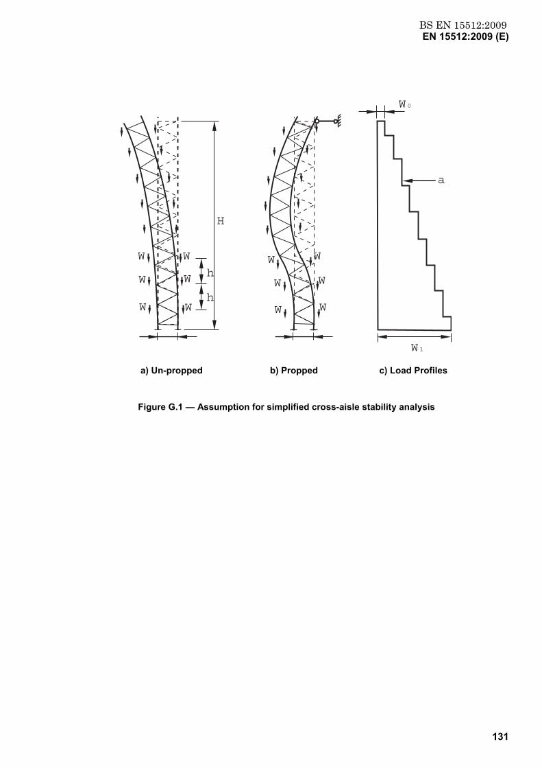
BS EN 15512:2009EN 15512:2009 (E)
131
H
W
W
W
W
W
W
h
h
W
W
W
W
W
W
a
W0
W1
a) Un-propped b) Propped c) Load Profiles
Figure G.1 — Assumption for simplified cross-aisle stability analysis
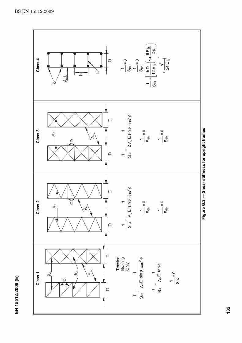
BS EN 15512:2009EN
155
12:2
009
(E)
132
Cla
ss 1
DD
Ad Ah
Au
Tens
ion
Brac
ing
O
nly
0 = S1
ta
n E
A1
= S1
co
s
sin
E A
1 =
S1
db
hdh
2d
dd
φ
φφ
Cla
ss 2
DD
AuAd
0 = S1
0 = S1
co
s
sin
E A
1 =
S1
dbdh
2d
ddφ
φ
Cla
ss 3
DD
AuAd
0 = S1
0 = S1
co
s
sin
E A 2
1 =
S1
dbdh
2d
ddφ
φ
Cla
ss 4
h
D
Ib
Au,Iu
kf
I E 24
h +
k D
I E 6 + 1I E
12D h
= S1
0 = S1
0 = S1
u
2
fb
bdb
dhdd
Figu
re G
.2 —
She
ar s
tiffn
ess
for u
prig
ht fr
ames
BS EN 15512:2009EN 15512:2009 (E)
133
Annex H (informative)
Factory production control (FPC)
H.1 General
This Annex provides guidance on suitable factory production control regimes in order to satisfy the requirements of this document.
H.2 Frequency of tests
The frequency of testing should ensure that components produced are manufactured from the materials specified to within the tolerance limits and perform as specified.
H.3 Bending tests on beam end connectors
At least one pair of connectors each month, selected at random, should be tested in such a way that over a period of time statistical quality control is achieved for every connector in the range. The manufacturer should select the combination of beam and uprights which will be used for these tests.
The results of such tests should be accumulated and treated statistically in order to obtain the characteristic values. Where at least 20 test results have been accumulated over a long period, the oldest of those in excess of 20 which are more 12 months old may be discarded.
Individual results for the moment of resistance of the beam end connector should be accepted provided they exceed the characteristic value adopted for the design.
Individual results for the stiffness of the beam end connector should satisfy the relationship:
kd + 2s ≥ k i ≥ kd - 2s (H.1)
where
kti = observed value of the stiffness;
kd = design value of the stiffness;
s = standard deviation of the accumulated results.
When an individual result does not satisfy one of these conditions, a set of design tests should be made on at least three connectors selected from the same production batch, and the characteristic values for strength and stiffness should be derived in accordance with this section.
If the characteristic values obtained satisfy the design requirements, then the batch may be accepted. If this is not the case, either the batch should be rejected, or the performance data of the product should be reduced.

BS EN 15512:2009EN 15512:2009 (E)
134
H.4 Bend tests
When the basic property of a steel type is determined by tensile tests in accordance with 8.1 a single bend test in accordance with A.1.2 should also be carried out as part of FPC.
BS EN 15512:2009EN 15512:2009 (E)
135
Annex I (informative)
A–deviations
A-deviation: National deviation due to regulations, the alteration of which is for the time being outside the competence of the CEN/CENELEC member.
This European Standard does not fall under any Directive of the EU. In the relevant CEN/CENELEC countries these A-deviations are valid instead of the provisions of the European Standard until they have been removed.
I.1 Dutch national legislative deviations
In the Netherlands racking and shelving and therefore adjustable pallet racking is, apart from work equipment, also to be considered as “construction work not being a building” according to the Building Decree 2003 {Bouwbesluit 2003 Besluit van 7 augustus 2001, houdende vaststelling van voorschriften met betrekking tot het bouwen van bouwwerken uit het oogpunt van veiligheid, zoals deze luidt na verwerking van de Besluiten van 17 april 2002, Stb 2002, 203, gepubliceerd 7 mei 2002; van 16 oktober 2002, Stb 2002, 516, gepubliceerd 24 oktober 2002; van 22 oktober 2002, Stb 2002, 518, gepubliceerd 29 oktober 2002; van 17 december 2004, Stb 2005, 368, gepubliceerd 26 juli 2005; 13 augustus 2005, Stb 2005, 417, gepubliceerd 25 augustus 2005, Stb. 2005, 528, gepubliceerd 27 oktober 2005, Stb. 2006, 148, gepubliceerd 21 maart 2006, Stb. 2006, 257, gepubliceerd 6 juni 2006 en Stb. 2006, 586, 30 november 2006)}. The structural safety of adjustable pallet racking considering its specified use, shall therefore comply with NEN 6700 (equivalent: EN 1990), NEN 6770 (equivalent: EN 1993-1-1) and NEN 6773 (equivalent: EN 1993-1-3). This implements that to comply with the Building Decree 2003, EN 15512 shall be considered together with NEN 5056.
I.2 German national legislative deviations
The following national deviations were decided on by the National Working Committee at its meeting on 2006.05.24 (the deviations are underlined):
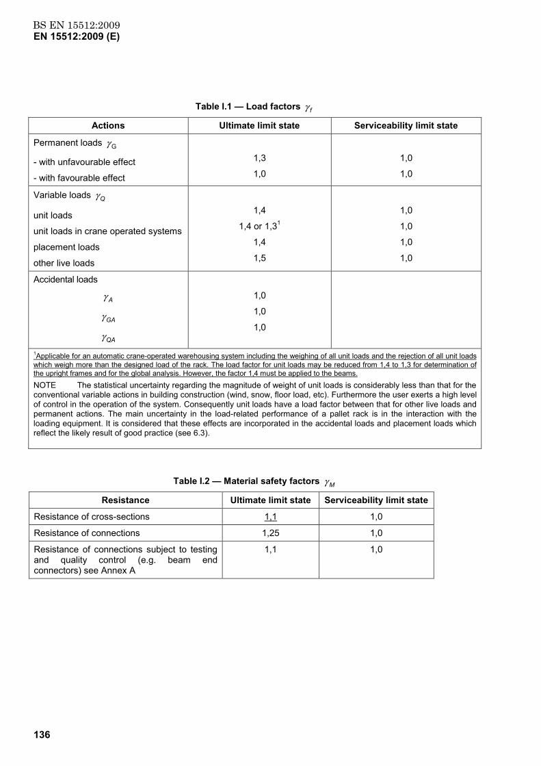
BS EN 15512:2009EN 15512:2009 (E)
136
Table I.1 — Load factors γ f
Actions Ultimate limit state Serviceability limit state
Permanent loads γ G
- with unfavourable effect
- with favourable effect
1,3
1,0
1,0
1,0
Variable loads γ Q
unit loads
unit loads in crane operated systems
placement loads
other live loads
1,4
1,4 or 1,31
1,4
1,5
1,0
1,0
1,0
1,0
Accidental loads
γ A
γ GA
γ QA
1,0
1,0
1,0
1Applicable for an automatic crane-operated warehousing system including the weighing of all unit loads and the rejection of all unit loads which weigh more than the designed load of the rack. The load factor for unit loads may be reduced from 1,4 to 1,3 for determination of the upright frames and for the global analysis. However, the factor 1,4 must be applied to the beams. NOTE The statistical uncertainty regarding the magnitude of weight of unit loads is considerably less than that for the conventional variable actions in building construction (wind, snow, floor load, etc). Furthermore the user exerts a high level of control in the operation of the system. Consequently unit loads have a load factor between that for other live loads and permanent actions. The main uncertainty in the load-related performance of a pallet rack is in the interaction with the loading equipment. It is considered that these effects are incorporated in the accidental loads and placement loads which reflect the likely result of good practice (see 6.3).
Table I.2 — Material safety factors γ M
Resistance Ultimate limit state Serviceability limit state
Resistance of cross-sections 1,1 1,0
Resistance of connections 1,25 1,0
Resistance of connections subject to testing and quality control (e.g. beam end connectors) see Annex A
1,1 1,0

BS EN 15512:2009EN 15512:2009 (E)
137
Bibliography
[1] J M Davies and J S Cowen "Pallet racking using cold-reduced steel" 12th International Speciality Conference on Cold-Formed Steel Design and Construction, St Louis, USA 18-19 October 1994, 641-655
[2] pr-FEM 10.2.08 "Recommendations for the design of static steel pallet racks under seismic conditions" Edition: 20th December 2005
BS EN15512:2009
BSI GroupHeadquarters 389Chiswick High Road,London, W4 4AL, UKTel +44 (0)20 8996 9001Fax +44 (0)20 8996 7001www.bsigroup.com/standards
BSI - British Standards InstitutionBSI is the independent national body responsible for preparing BritishStandards. It presents the UK view on standards in Europe and at theinternational level. It is incorporated by Royal Charter.
Revisions
British Standards are updated by amendment or revision. Users of BritishStandards should make sure that they possess the latest amendments oreditions.
It is the constant aim of BSI to improve the quality of our products and services.We would be grateful if anyone finding an inaccuracy or ambiguity while usingthis British Standard would inform the Secretary of the technical committeeresponsible, the identity of which can be found on the inside front cover. Tel:+44 (0)20 8996 9000. Fax: +44 (0)20 8996 7400.
BSI offers members an individual updating service called PLUS which ensuresthat subscribers automatically receive the latest editions of standards.
Buying standards
Orders for all BSI, international and foreign standards publications should beaddressed to Customer Services. Tel: +44 (0)20 8996 9001. Fax: +44 (0)20 89967001 Email: [email protected] You may also buy directly using a debit/creditcard from the BSI Shop on the Website http://www.bsigroup.com/shop
In response to orders for international standards, it is BSI policy to supply theBSI implementation of those that have been published as British Standards,unless otherwise requested.
Information on standards
BSI provides a wide range of information on national, European andinternational standards through its Library and its Technical Help to ExportersService. Various BSI electronic information services are also available whichgive details on all its products and services. Contact Information Centre. Tel:+44 (0)20 8996 7111 Fax: +44 (0)20 8996 7048 Email: [email protected]
Subscribing members of BSI are kept up to date with standards developmentsand receive substantial discounts on the purchase price of standards. For detailsof these and other benefits contact Membership Administration. Tel: +44 (0)208996 7002 Fax: +44 (0)20 8996 7001 Email: [email protected]
Information regarding online access to British Standards via British StandardsOnline can be found at http://www.bsigroup.com/BSOL
Further information about BSI is available on the BSI website at http://www.bsigroup.com.
Copyright
Copyright subsists in all BSI publications. BSI also holds the copyright, in theUK, of the publications of the international standardization bodies. Except aspermitted under the Copyright, Designs and Patents Act 1988 no extract maybe reproduced, stored in a retrieval system or transmitted in any form or by anymeans – electronic, photocopying, recording or otherwise – without prior writtenpermission from BSI.
This does not preclude the free use, in the course of implementing the standard,of necessary details such as symbols, and size, type or grade designations. Ifthese details are to be used for any other purpose than implementation then theprior written permission of BSI must be obtained.
Details and advice can be obtained from the Copyright and Licensing Manager.Tel: +44 (0)20 8996 7070 Email: [email protected]