Embed Size (px)
Citation preview
CQ
ID m
o
*<"„
REG
RAO
ED U
NC
LA
SS
IFIE
D B
Y
AU
TW
OR
lJY
OF
OO
OD
iR.
5200.
1 R
BY
° Is
1^3
HK; w
WARNING
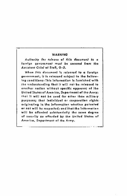
Authority for release of this document to a foreign government must be secured from fhe Assistant Chief of Staff, G-2.
When .this document is released fo a foreign government, it is released subject fa the follow ing conditions: This information Is furnished with the understanding that it will not be released to another nation without specific approval of ithe United States of America, Department of the Army; that it will not be used far other than military purposes; that individual or corporation rights originating in tho information whether patented or not will be respected; and that the Information will be afforded substantially the same degree of security as afforded by the United States of America, Department of the Army.
FM 23-15 C 3
FIELD MANUAL
BROWNING AUTOMATIC RIFLE CALIBER .30 M1918A2
FM 23-15 ) DEPARTMENT OF THE ARMY CHANGES No. 3^ WASHINGTON 25, D. C., 28 May 1957
. FM 23-15, 9 July 1951, is changed as follows:
13. Disassembly of the.Trigger Group
To disassemble the trigger group
c. To remove the * * * the sear spring. An alternate method of removing the sear spring can be used as follows. Place the trigger group on a flat sur face with the magazine guides toward your body. Using a dummy cartridge, insert the point into the notch on the square end of the sear spring, and push forward unseating the sear spring (fig. 38.1). Remove the sear spring.
21. General
(Superseded)
An automatic rifleman is not expected to be a tech nical expert on the automatic rifle, but must under stand functioning, or how and why the automatic rifle operates. With an understanding of functioning, stoppages can be located and reduced quickly.
TAGO 6587C-May ,
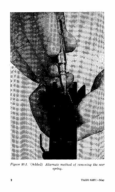
Figure 38.1. (Added) Alternate method oj removing the sear spring.
TAGO 6587C—May
22. What Functioning Is
(Superseded)
a. Functioning is the operations of loading, firing, and unloading of a firearm. This is known as the cycle of operation. This cycle is similar in all small arms weapons.
b. The cycle of operation is broken down into eight steps
(1) Feeding.(2) Chambering. ^(3) Locking.(4) Firing.(5) Unlocking.(6) Extracting.(7) Ejecting.(8) Cocking.
c. As functioning of the operating group is dis cussed, remember that some of the steps occur at the same time.
22.1 Feeding
(Added)
a. Feeding is the action of placing a cartridge in the receiver in back of the barrel ready for chamber ing.
b. This action is accomplished by the magazine exerting an upward pressure on the bottom of the magazine follower causing the cartridge to be forced up into the path of the feed rib ready for chambering.
c. Feeding starts during the rearward movement of the bolt. As the feed rib clears the top round in the
TAGO 8587C~May 3
magazine on the rearward movement, the compressed magazine spring moves the top round up into the path of the feed rib.
22.2 Chambering
(Added)
a. Chambering is the action of stripping the round from the magazine and loading it into the chamber ready for firing.
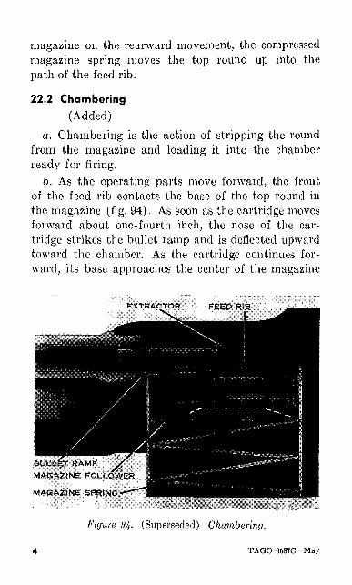
6. As the operating parts move forward, the front of the feed rib contacts the base of the top round in the magazine (fig. 94). As soon as the cartridge moves forward about one-fourth inch, the nose of the car tridge strikes the bullet ramp and is deflected upward toward the chamber. As the cartridge continues for ward, its base approaches the center of the magazine
Figure 94- (Superseded) Chambering.
TAGO 6587C May
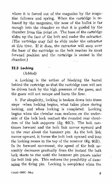
where it is forced out of the magazine by the maga zine follower and spring. When the cartridge is re leased by the magazine, the nose of the bullet is far enough into the chamber so that it is guided by the chamber from this point on. The base of the cartridge slides up the face of the bolt and under the extractor. (The cartridge may fail to slide under the extractor at this time. If it does, the extractor will snap over the base of the cartridge as the bolt reaches its most forward position and the cartridge is seated in the chamber.)
22.3 Locking
(Added)
a. Locking is the action of blocking the barrel behind the cartridge so that the cartridge case will not be driven back by the high pressure of the gases, and the gases will not escape and harm the firer.
b. For simplicity, locking is broken down into three steps when locking begins, what takes place during locking, and when locking is completed. Locking begins when the circular cam surfaces on the under side of the bolt lock contact the rounded rear shoul ders of the bolt supports (fig. 95C). The bolt con tinues forward and the bolt link moves -upward and to the rear about the hammer pin. As the bolt link moves upward, it forces the bolt lock upward and into the locking recess in the top of the receiver (fig. 95B). In its forward movement, the speed of the bolt as sembly decreases gradually from the instant the bolt lock starts to rise until the hammer pin passes under the bolt link pin. This reduces the possibility of dam aging the firing pin. Locking is completed when the
TAGO 6S87C May s
hammer pin is directly under the bolt link pin (fig. 95A).
22.4 Firing
(Added)a. Firing is the action of igniting the primer, or
actually firing the cartridge.6. The tang of the firing pin is buried in the slot
on the underside of the bolt lock at all times except when the bolt lock is in the locking recess. This keeps the head of the firing pin locked away from the center rib of the hammer during the. rearward and forward motion of the bolt assembly, so that the weapon can not fire. When locking is completed and the bolt lock is in the locking recess, the tang of the firing pin is no longer buried in the bolt lock, and the head of the firing pin can be struck by the center rib of the ham mer. The slide and hammer continue forward another one-tenth inch after the bolt lock is in the locking recess. The center rib of the hammer strikes the head of the firing pin, driving the firing pin forward a short distance through the feed rib. The firing pin striker hits the cartridge primer and fires the cartridge.
c. The forward movement of the slide is completed when the forward shoulders of the slide strike the rear shoulders of the gas cylinder tube. This action cushions the shock of the hammer striking the firing pin and reduces breakage of the firing pin.
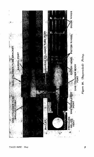
d. When a cartridge is fired, the bullet is driven through the barrel by the pressure from the expanding powder gas. About 6 inches from the muzzle, the bullet passes a small hole in the bottom of the barrel. This hole is called the barrel port (fig. 96).
6 TAGO 6587C May
O o
GU
IEft R
ING
S
GA
S C
YL
IND
ER
BO
DY
P
OR
T
Fig
ure
96.
(Sup
erse
ded)
F
irin
g.
e. As the bullet passes the barrel port, some of the gas under high pressure passes through it. Gas con tinues to pass through the gas ports for the short time that it takes the bullet to travel the 6 inches from the barrel port to the muzzle. Figure 96 shows the path taken by the gas. First it goes through the barrel port, then the gas cylinder tube bracket port, the gas cylinder tube port, the gas cylinder body port, the gas regulator port, and then into the gas cylinder well. The gas regulator port is the smallest of the four gas ports. It controls the amount of gas entering the gas cylinder assembly. All of the gas ports are stationary except the gas regulator port. There are three differ ent sized gas regulator ports.
/. When the gas rushes into the gas cylinder, it strikes the gas piston head a sharp blow, moving the piston to the rear. Note the three piston rings near the head of the gas piston. When the gas piston has moved approximately nine-sixteenth of an inch, the three piston rings and the gas piston move out of the gas cylinder assembly. The gas then expands around the piston head and escapes from the six gas escape ports in the gas cylinder tube and the pressure relief vent in the gas cylinder assembly. Any gas remaining in the barrel escapes as soon as the bullet leaves the muzzle.
g. The two guide or bearing rings on the gas piston serve two purposes. They prevent the escape of gas back into the operating parts, and hold the front end of the gas piston in the center of the gas cylinder tube after the gas piston head has moved out of the gas cylinder assembly.
h. Because the slide is attached to the piston, it
8 TAGO 6587C May
moves when the piston moves. As the piston and slide move to the rear, the recoil spring is compressed, storing energy for the forward movement, and the weapon is unlocked. The center rib of the hammer is withdrawn from the head of the firing pin during the initial movement of the slide to the rear.
23. The Functioning Cycle
Rescinded
24. Functioning of the Operating Group
Rescinded
25. Action of the Gas
Rescinded
26. Movement of the Slide of the Rear
Rescinded
27. Unlocking
(Superseded)
a. Unlocking is the action of unblocking the breech end of the rifle. For simplicity, unlocking is studied in three steps when unlocking begins, what takes place during unlocking, and when unlocking is com pleted.
b. When the operating parts are completely for ward, the hammer pin is 0.19 inch ahead of the bolt link pin. The center rib of the hammer is slightly in rear of the head of the firing pin. During the first 0.19- inch movement of the slide assembly to the rear, the bolt and bolt lock do not move. The gas pressure is being reduced. The unlocking action begins when the
TAGO 6587C May o
hammer pin-is directly under the bolt link pin (A, fig. 95).
c. As the slide continues to the rear, the bolt link moves forward and downward about the hammer pin (B, fig. 95) The bolt lock is drawn downward, to the rear, and out of the locking recess.
d. Unlocking is completed when the bolt lock is completely down and out of the locking recess (C, fig. 95). At this point the slide has moved 1.39 inches to the rear, and the bolt, bolt lock, and slide are moving to the rear at the same speed. The bolt lock is now supported by the bolt supports. The bolt and bolt lock do not attain the speed of the slide until the bolt lock has moved 1.39 inches to the rear. This is very important for two reasons. First, the parts are not subjected to an undue strain because of the sudden start when the cartridge explodes. Second, the slow initial movement delays the opening of the chamber. By the time the chamber opens, the gas pressure has been reduced.
e. As the bolt lock moves downward from the lock ing recess, the firing pin is withdrawn (B, fig. 95). A cam surface in the slot on the underside of the bolt lock operates on a cam surface on the tang of the firing pin. This action withdraws the striker of the firing pin back into the face of the bolt.
28. Withdrawal of the Firing PinRescinded
29. Extraction
(Superseded)a. Extraction is the action of removing the cartridge
or fired cartridge case from the chamber.
10 TAGO 6587C-May
6. The extractor is located on the upper right side of the bolt next to the ejection opening. Keep in mind that the extractor grasps the base of the car tridge. This action holds the base of the cartridge firmly against the face of the bolt. When the auto matic rifle is fired, the empty cartridge case expands and binds against the chamber, so there must be some means of loosening the cartridge case before removing it. During their initial movement, the bolt and bolt lock move slowly in comparison with the movement of the slide. As the bolt lock moves downward from the locking recess during unlocking, the circular cam surfaces on the underside of the bolt lock act on the rounded rear shoulders of the bolt supports (B, fig. 95). This contact produces a strong lever action, known as slow initial extraction, that loosens the empty cartridge case. When the bolt lock is down and out of the locking recess, the bolt drawn by the bolt lock and bolt link moves to the rear with the same speed as the slide assembly. The empty case is car ried with and held against the face of the bolt by the extractor.
30. Ejecting
(Superseded)
a. Ejecting is the action of removing the cartridge or fired cartridge case from the rifle after it has been extracted from the chamber.
6. The ejector is located on the trigger group. When the slide reaches a point approximately one-fourth inch from the end of its travel, the base of the car tridge case strikes the ejector. The cartridge case pivots about the extractor and passes through the
TAGO 6587C May , 1
ejection opening. As the bolt continues to the rear, the cartridge case strikes the side of the receiver to the rear of the ejection opening and is ejected to the right front.
30.1 Cocking
(Added)
a. Cocking is the action of placing the parts in readiness for firing.
5. Cocking begins with the initial movement of the slide to the rear, and is completed when the rear of the slide strikes the sear release and buffer head, and the recoil spring is fully compressed.
c. As the parts move to the rear, the recoil spring is being compressed. This action stores the necessary energy for the forward movement. The operating parts will move forward if the trigger is held or pressed to the rear. If the trigger is released, the sear will engage the sear notch on the underside of the slide, halting the firing cycle. When the trigger is pressed, the sear nose is depressed and is disengaged from the sear notch on the slide. The slide assembly is then free to move forward under the force of the expanding recoil spring. As the slide moves forward, it carries the operating parts with it.
32. Action of the Recoil Spring
Rescinded
33. Feeding
Rescinded
34. Locking
Rescinded
1 2 TAGO 6587C May
35. Firing the Cartridge
Rescinded
36. Termination of the Forward Movement
Rescinded
53. Gas Adjustment
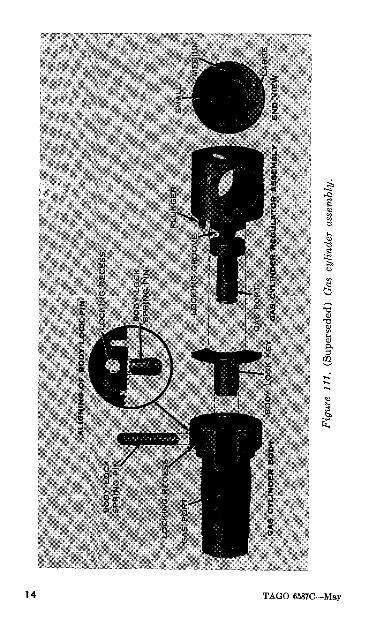
d. (Added) A new gas cylinder assembly has been devised and is composed of the following parts: gas cylinder body, body lock key, regulator, and the body lock spring pin (fig. 111). On the face of the regulator there are three circles of different sizes. These circles correspond with similar size gas ports in the body of the regulator. The rifle is normally operated with the regulator on the smallest port and the setting is not varied unless the rifle shows signs of insufficient gas.
e. (Added) The disassembly and assembly of the gas cylinder assembly may be facilitated by first removing the gas cylinder tube and wooden forearm from the rifle.
/. (Added) To disassemble the gas cylinder assem bly, first drift out the body lock spring pin from its recess in the gas cylinder body. This can be accom plished using a drift or nail and tapping lightly with the combination tool (care must be taken to insure that the body lock spring pin is not damaged). Next, remove the gas regulator by pulling it out of its recess in the gas cylinder body. Lift out the body lock key from its locking recess in the gas cylinder body, then unscrew the body from the gas cylinder tube in a counterclockwise manner.
TAGO 6S87C May j 3
O
O
Fig
ure
111.
(S
uper
sede
d)
Gas
cyl
inde
r as
sem
bly.
g. (Added) To assemble the gas cylinder assembly, screw the gas cylinder body into the gas cylinder tube fingertight, and back off until the gas cylinder body port is perfectly alined with the gas cylinder tube port (this can be accomplished by observing the aline- ment of the gas ports when held up to the light as viewed from the gas cylinder tube port). If the gas cylinder tube is not disassembled from the rifle, this alinement can be accomplished by screwing the gas cylinder body into the gas cylinder tube fingertight, and backing off until the locking recess on the gas cylinder body is directly under the barrel. If the locking recess is not under the barrel in either case, the alincment of the gas ports has not been completed and the rifle will not function. Next, lock the gas cylinder body in position by inserting the body lock key into its recess. Insert the regulator into the gas cylinder body making sure that the regular plunger does not rest on any portion of the body lock key, and lock it in position with the body lock spring pin (before the body lock spring pin is inserted, push in lightly on the regulator to compress the regulator plunger so the holes in the gas cylinder body are alined with the locking groove on the regulator to receive the body lock spring pin). The body lock spring pin must be so positioned so that the groove in the spring is alined with either edge of the regulator groove. This prevents binding and damaging of the body lock spring pin.
h. (Added) In turning the regulator, notice that it turns under pressure. The regulator plunger is con stantly exerting pressure on the gas cylinder body when the regulator is assembled and locked in position.
TAGO 6587C-May ] 5
This prevents the regulator from turning during firing. Also, as the regulator moves, notice that it moves in clicks, each click being a gas setting. If the regulator is positioned between ports or clicks, no gas will pass through the regulator as the gas ports are out of alinement.
i. (Added) To adjust the gas setting on the smallest port, turn the regulator to the extreme clockwise posi tion. It is prevented from turning further by the regulator plunger contacting the body lock key. To check this, see that the small circle on the face of the regulator is directly under the barrel.
j. (Added) If upon firing, the rifle shows signs of insufficient gas, adjust the regulator to the next larger port (medium). This is done by backing the regulator off one click to the left, or counterclockwise, until the medium hole on the face of the regulator is alined under the barrel.
k. (Added) If the rifle still shows signs of insuffi cient gas, adjust the regulator to the large port by turning the regulator to the extreme left or counter clockwise position until the large hole on the face of the regulator is alined under the barrel.
I. (Added) The large port is provided for use in case the action of the rifle becomes sluggish through the collection of dirt or the lack of oil under conditions which render prompt corrective action impractical. In the absence of the above conditions, continued use of the regulator adjusted on the large port indicates either a poor alinement of the gas ports, a dirty gas cylinder assembly, or worn parts in the gas system.
16 TAGO 6587C May
Section V. STOPPAGES AND IMMEDIATE ACTION
(Superseded)
55. General
a. A stoppage is any unintentional interruption in the cycle of operation. In other words, a stoppage occurs when the rifle stops firing or fails to fire, through no fault of the automatic rifleman. A stop page may be a failure to feed, chamber, fire, extract, or eject. It is caused by faulty operation of the auto matic rifle, magazine, or ammunition.
6. A malfunction is a failure of the weapon to func tion satisfactorily. A malfunction may or may not become evident by actual stoppage of fire. In some cases, for example, when the trigger group does not function satisfactorily, the malfunction may be evi denced by a runaway rifle or one which fires semiauto matic fire when full automatic fire is desired. Mal functions may also be caused by forces and factors which do not exist at all times. Foreign material, such as dust, mud, or ice, may enter the mechanism and also produce malfunctions. A malfunction may result in a stoppage.
c. Immediate action is the prompt action taken by the firer to reduce a stoppage. It is an unhesitating action performed when his rifle fails to fire.
56. Common Causes of Stoppages
a. Stoppages are caused by worn, weak, broken, or dirty operating parts. An automatic rifleman must train himself to watch for these defects and correct them before they cause a stoppage. The primary
TAGO 6587C May ]7
cause of stoppages with the automatic rifle is a defec tive magazine. For this reason it is particularly im portant that the magazine be handled carefully. Take proper care of the magazines and the weapon itself, and the automatic rifle can be relied upon to function properly when it is needed. There are five types of stoppages common to the automatic rifle. Their usual causes and the action necessary to reduce them are described below. Examine the automatic rifle before, during, and after firing with these causes in mind. In this manner many stoppages can be prevented.
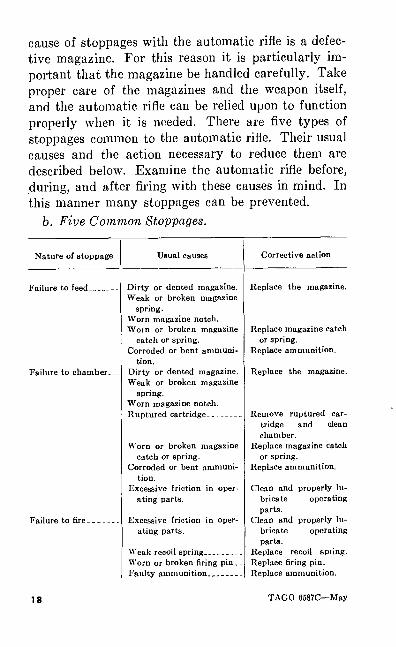
b. Five Common Stoppages.
Nature of stoppage
Failure to feed-
Failure to chamber---
Failure to fire.
Usual causes
Dirty or dented magazine.Weak or broken magazine
spring.Worn magazine notch.Worn or broken magazine
catch or spring.Corroded or bent ammuni
tion.Dirty or dented magazine.Weak or broken magazine
spring.Worn magazine notch.Ruptured cartridge. _.____.
Worn or broken magazine catch or spring.
Corroded or bent ammuni tion.
Excessive friction in oper ating parts.
Excessive friction in oper ating parts.
Weak recoil spring__-,__ Worn or broken firing pin. Faulty ammunition__,_-_-
Corrective action
Replace the magazine.
Replace magazine catchor spring.
Replace ammunition.
Replace the magazine.
Remove ruptured car tridge and clean chamber.
Replace magazine catch or spring.
Replace ammunition.
Clean and properly lu bricate operating parts.
Clean and properly lu bricate operating parts.
Replace recoil spring.Replace firing pin.Replace ammunition.
18 TAGO 6587C May
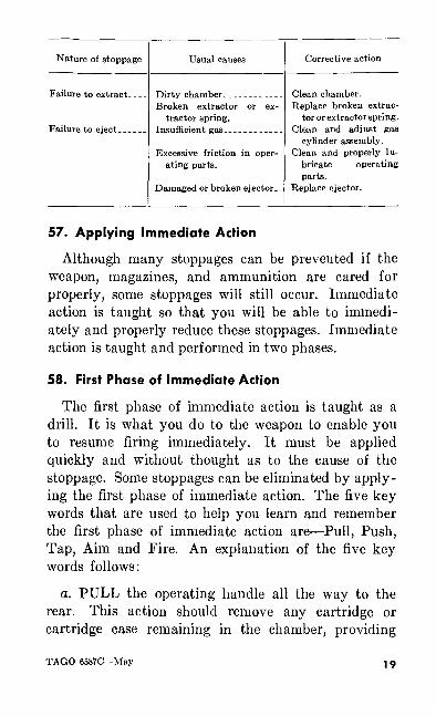
Nature of stoppage
Failure to extract____
Failure to eject. __
Usual causes
Dirty chamber. _ __________ Broken extractor or ex
tractor spring.
Excessive friction in oper ating parts.
Damaged or broken ejector. _
Corrective action
Clean chamber. Replace broken extrac
tor or extractor spring .
cylinder assembly. Clean and properly lu
bricate operating parts.
Replace ejector.
57. Applying Immediate Action
Although many stoppages can be prevented if the weapon, magazines, and ammunition are cared for properly, some stoppages will still occur. Immediate action is taught so that you will be able to immedi ately and properly reduce these stoppages. Immediate action is taught and performed in two phases.
58. First Phase of Immediate Action
The first phase of immediate action is taught as a drill. It is what you do to the weapon to enable you to resume firing immediately. It must be applied quickly and without thought as to the cause of the stoppage. Some stoppages can be eliminated by apply ing the first phase of immediate action. The five key words that are used to help you learn and remember the first phase of immediate action are Pull, Push, Tap, Aim and Fire. An explanation of the five key words follows:
a. PULL the operating handle all the way to the rear. This action should remove any cartridge or cartridge case remaining in the chamber, providing
TAGO 6587C May 19
the extractor, extractor spring, or the ejector is not broken.
6. PUSH the operating handle all the way forward. The weapon is now cocked.
c. TAP up firmly on the bottom of the magazine. If the magazine is not fully seated, this should seat it, providing the magazine notch or magazine catch is not worn.
d. AIM and FIRE.(Apply the first phase only once. If this fails to
reduce the stoppage, apply the second phase.)
59. Second Phase of Immediate Action
If the first phase of immediate action fails to reduce the stoppage, then a more detailed examination of the automatic rifle must be made. The five key words used to help you remember the second phase of im mediate action are Take, Look, Pull, Locate, and Reduce. An explanation of these five words follows:
a. TAKE the automatic rifle from the shoulder.b. LOOK at the ejection opening.c. PULL the operating handle slowly to the rear.d. LOCATE the stoppage by observing, as you pull
the operating handle to the rear, what is in the ejec tion opening, what is in the chamber, or what is ejected.
e. REDUCE the stoppage and continue to fire.
60. Stoppages
While applying the second phase of immediate ac tion, you will see certain stoppages. You must be able to locate their causes and reduce them. Some of the more common stoppages are
20 TAGO 6587C May
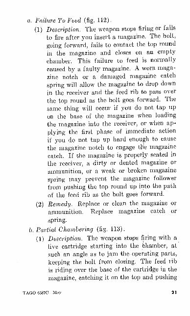
a. Failure To Feed (fig. 112).
(1) Description. The weapon stops firing or fails
to fire after you insert a magazine. The bolt, going forward, fails to contact the top round
in the magazine and closes on an empty chamber. This failure to feed is normally
caused by a faulty magazine. A worn maga zine notch or a damaged magazine catch
spring will allow the magazine to drop down in the receiver and the feed rib to pass over the top round as the bolt goes forward. The
same thing will occur if you do not tap up on the base of the magazine when loading the magazine into the receiver, or when ap plying the first phase of immediate action
if you do not tap up hard enough to cause the magazine notch to engage the magazine catch. If the magazine is properly seated in the receiver, a dirty or dented magazine or ammunition, or a weak or broken magazine spring may prevent the magazine follower
from pushing the top round up into the path of the feed rib as the bolt goes forward.
(2) Remedy. Replace or clean the magazine or ammunition. Replace magazine catch or spring.
b. Partial Chambering (fig. 113).
(1) Description. The weapon stops firing with a live cartridge starting into the Chamber, at such an angle as to jam the-operating parts, keeping the bolt from closing. The feed rib
is riding over the base of the cartridge in the magazine, catching it on the top and pushing
TAGO 6587C May 21
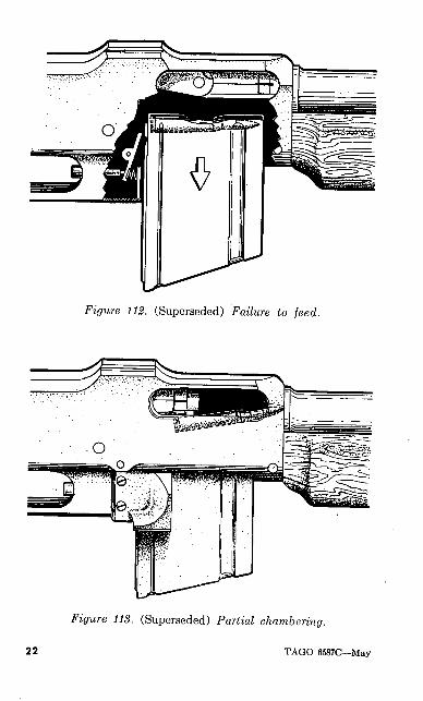
Figure 112. (Superseded) Failure to feed.
Figure 113. (Superseded) Partial chambering.
22 TAGO 6587C—May
it part way into the chamber as shown in figure 113. This type of stoppage is caused by a faulty magazine, faulty ammunition, or a worn or damaged magazine catch or catch spring under the same condition as with the failure to feed. The only difference is that the bolt does contact the top round forcing it partially into the chamber.
(2) Remedy. Replace or clean the magazine or ammunition. Replace the magazine catch or spring.
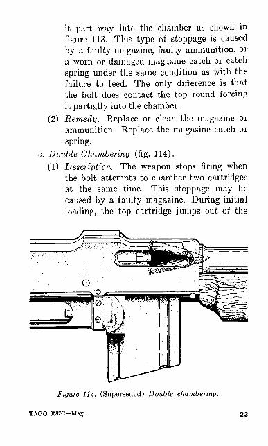
c. Double Chambering (fig. 114).(1) Description. The weapon stops firing when
the bolt attempts to chamber two cartridges at the same time. This stoppage may be caused by a faulty magazine. During initial loading, the top cartridge jumps out of the
Figure 114. (Superseded) Double chambering.
TAGO 6587C—Max 23
magazine. As the bolt moves forward the feed rib contacts the top round in the maga zine, causing two cartridges to move forward for chambering, resulting in a jam. This stoppage may be caused when applying the first phase of immediate action to a partial chambering. In any case, the stoppage is due to magazine trouble.
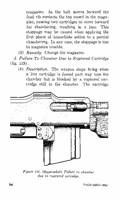
(2) Remedy. Change the magazine. d. Failure To Chamber Due to Ruptured Cartridge
(fig. 115).(1) Description. The weapon stops firing when
a live cartridge is forced part way into the chamber but is blocked by a ruptured car tridge still in the chamber. The cartridge
Figure 115. (Superseded) Failure to chamber due to ruptured cartridge.
24 TAGO 6587C—May
which is in the chamber was ruptured be cause of a dirty chamber, faulty ammunition, or excessive head space. A stoppage result ing from excessive head space is very rare.
(2) Remedy. Clean the chamber and check or replace faulty ammunition. In rare instances the head space must be adjusted. If the head space needs adjustment, turn the weapon in to ordnance.
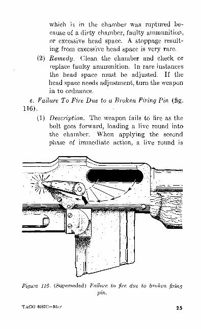
e. Failure To Fire Due to a Broken Firing Pin (fig. 116).
(1) Description. The weapon fails to fire as the bolt goes forward, loading a live round into the chamber. When applying the second phase of immediate action, a live round is
Figure 116. (Superseded) Failure to fire due to broken firingpin.
TAGO 6587C—May 25
ejected from the receiver with the primer not dented.
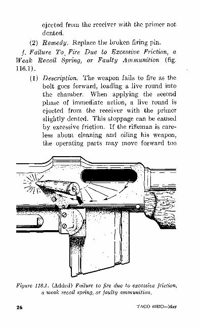
(2) Remedy. Replace the broken firing pin. /. Failure To_ Fire Due to Excessive Friction, a
Weak Recoil Spring, or Faulty Ammunition (fig.116.1).
(1) Description. The weapon fails to fire as the bolt goes forward, loading a live round into the chamber. When applying the second phase of immediate action, a live round is ejected from the receiver with the primer slightly dented. This stoppage can be caused by excessive friction. If the rifleman is care less about cleaning and oiling his weapon, the operating parts may move forward too
Figure 116.1. (Added) Failure to fire due to excessive friction, a weak recoil spring, or faulty ammunition.
26 TAGO 6587C-May
slowly for the firing pin to strike the primer with sufficient force to ignite the cartridge. The same result would be obtained if the weapon has a weak recoil spring. If none of the above, the failure to fire will un doubtedly be due to faulty ammunition.
(2) Remedy. Clean and oil the weapon, or re place the weak recoil spring. If repeatedly caused by faulty ammunition, suspend use of that particular lot of ammunition and report to the ammunition officer.
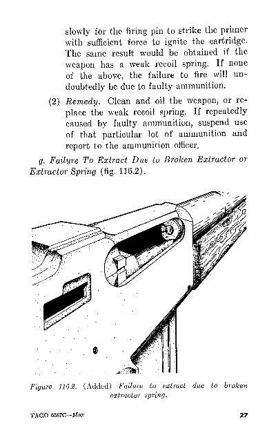
g. Failure To Extract Due to Broken Extractor or
Extractor Spring (fig. 116.2).
Figure 116.2. (Added) Failure Lo extract due to broken extractor spring.
TAGO 6587C—May 27
(1) Description. The weapon stops firing when an empty cartridge case, not extracted, blocks the entry of a live cartridge into the chamber. This type of stoppage is caused by a worn or broken extractor or extractor spring.
(2) Remedy. Replace worn or broken extractor or extractor spring.
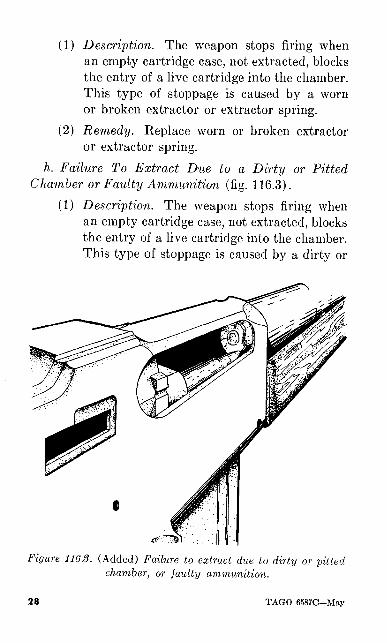
h. Failure To Extract Due to a Dirty or Pitted Chamber or Faulty Ammunition (fig. 116.3).
(1) Description. The weapon stops firing when an empty cartridge case, not extracted, blocks the entry of a live cartridge into the chamber. This type of stoppage is caused by a dirty or
Figure 1163. (Added) Failure to extract due to dirty or -pitted chamber, or faulty ammunition.
28 TAGO 6587C—May
pitted chamber or faulty ammunition. The empty cartridge case was wedged so tightly against the walls of the chamber, or was so weak, that it was easier for the.extractor to pull off part of the rim of the cartridge case than to extract it from the chamber.
(2) Remedy. Remove empty cartridge case and clean the chamber. Replace faulty ammuni tion. If the chamber is pitted, turn the weapon in to ordnance.
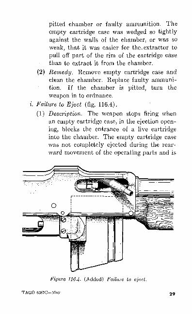
i. Failure to Eject (fig. 116.4).(1) Description. The weapon stops firing when
an empty cartridge case, in the ejection open ing, blocks the entrance of a live cartridge into the chamber. The empty cartridge case was not completely ejected during the rear ward movement of the operating parts and is
Figure 116.4- (Added) Failure to eject.
TAGO 6587C—May 29
wedged in the ejection opening as the operat ing parts came forward. This type of stop page is caused by insufficient gas, excessive friction, or a broken or worn ejector. Insuffi cient gas may be the result of a dirty gas system. If the operating parts are dirty, the gas striking the piston may not be sufficient to overcome the resulting friction in the oper ating parts. In either case, the operating parts do not move to the rear with sufficient force to eject the empty cartridge case from the receiver. The same action will occur with a worn out or broken ejector. Be con tinually alert for weak ejection by observing the ejecting of the empty cartridge cases. They should eject to the right front approxi mately 2 to 4 yards. If empty cartridge cases are dropping next to the receiver, this indicates insufficient gas.
(2) Remedy. Clean and adjust gas system. Clean and oil the operating parts. Replace worn or broken ejector.
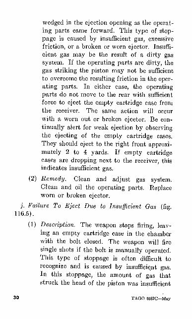
j. Failure To Eject Due to Insufficient Gas (fig. 116.5).
(1) Description. The weapon stops firing, leav ing an empty cartridge case in the chamber with the bolt closed. The weapon will fire single shots if the bolt is manually operated. This type of stoppage is often difficult to recognize and is caused by insufficient gas. In this stoppage, the amount of gas that struck the head of the piston was insufficient
30 TAGO 6587C-May
to drive the piston far enough to the rear to eject the empty cartridge case completely.
(2) Remedy. Set the gas regulator on the next larger port or clean the gas cylinder assembly. Clean the chamber if dirty.Note. If, after cleaning and adjusting gas cylinder
assembly, the stoppage persists, check for worn or damaged part in the gas system.
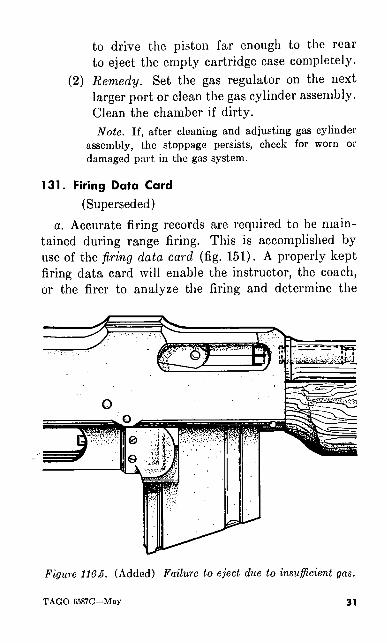
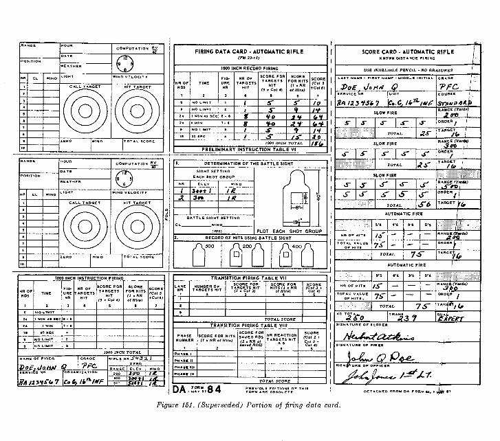
131. Firing Data Card
(Superseded)a. Accurate firing records are required to be main
tained during range firing. This is accomplished by use of the firing data card (fig. 151). A properly kept firing data card will enable the instructor, the coach, or the firer to analyze the firing and determine the
Figure 116£. (Added) Failure to eject due to insufficient gas.
TAGO 6587C—May 31
progress being made. By studying the card, they can determine whether or not errors are made in comput ing for the effect of the wind, or if the zero for each range is correct. By comparing the call target with the hit target, it can be determined how consistent the firer is in aiming, pressing the trigger, following through, and calling the shots. A properly used firing data card is a valuable aid in learning to shoot the automatic rifle accurately.
6. The firing data card should be kept as neatly as possible. A pencil should always be used to prevent loss of information in the event the card becomes damp. Upon receipt of the card, the firer should be instructed to complete the personal information called for on the front of the card: name, rank, serial num ber, etc. His rifle number should be entered on the
RANGE ZOO
POSITION
ZfffO
HOURO8OO
DATE . . ZO/9/S6
WEATHER coot
COMPUTATION
NR EL WINDLIGHT
tfffi/GHTWIND VELOCITY
2OCALL TARGET HIT GET
ZERO WIND10
TOTAL SCORE
. Figure 152. (Superseded) Firing data card completed jor
sample problem.
32 TAGO 6587C—May
CALL TARGET HIT TARGET
1000 INCH INSTRUCTION FIRING ___.
FIG- NROF *"™°R SC°RE
O LIMIT | S
1000 INCH TOTAL
4AME
>o.GRADE
TFC.l- § _~ R ft 33.
ZERO
FIRING DATA CARD - AUTOMATIC RIFLE<FM 23- IS)
1000 INCH RECORD FIRING
0 NO LIMIT
NR OFTARGETS
HIT
SCORE FOR
TARGETS
HITa « Co; «
fo
(Col S + Col 6)
*v
1000 INCH TOTAL
PRELIMINARY INSTRUCTION TABLE VI
10It
/•/
DETERMINATION OF THE BATTLE SIGHT
SIGHT SETTING
EACH SHOT GROUP
m
_WIND_
(3OO)
a——'9f-
PLOT EACH SHOT GROUPRECORD OF HITS USING BATTLE SIGHTt
TRANSITION FIRING TABLE VIISCORE FOR
TOTAL SCORE
TRANSITION FIRING TABLE VIII
TOTAL SCORE
SCORE(Col 3 t Co/ J - Cot 4)
SCORE CARD - AUTOMATIC RIFLEKNOWN DISTANCE FIRING
USE INDELIBLE PENCIL • NO ERASURES
3>0£\SERVICE NR
RANGE (Ysrdtt
Af
f ^ TARGET
r 6"AUTOMATIC FIRE
AUTOMATIC FIRE
if5'S 4'S 3'S O'S
75-TOTAL
A&0
DA.Z.T..84Figure 151. (Superseded) Portion of firing data card.
TRANSITION FIRING
TRANSITION FIRING TABLE V||
NR OFTARGETS
HIT
SCORE FOR TARGETS
HIT (3 * Col 2)
10
30
SCORE (Col 3 t Col 4)
(,<*
TRANSITION FIRING TABLE Vlll
10
/e10
Jo
fJiMC
COMBINED TOTAL
It*
SIGNATURE OF FERER
Ao
THE INFORMATION CONTAINED IN THIS SCORE CAF (Known Df.tanc* and Tr«n»Hlon Pirlnt) IS CORRECT:
Figure 151—(continued).
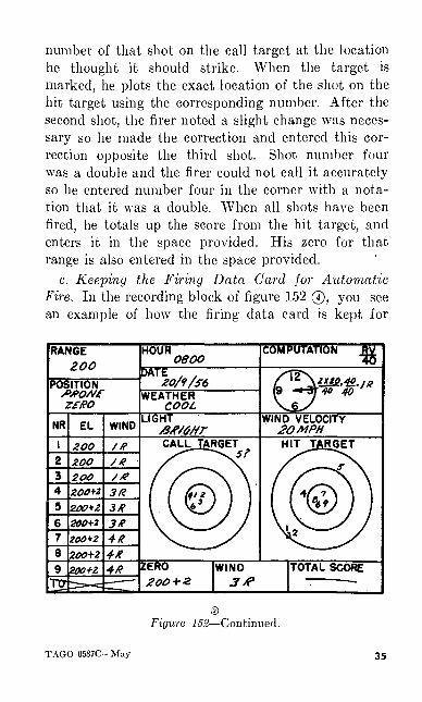
zero record card (fig. 151 ©). Notice the recording block in figure 152 ©. This shows the information that should be placed on the card just prior to firing. The range and position are entered. The weather and light are entered by using words of the firer's own choosing. For example, the weather may be described as cold, rainy, or clear; the light may be described as bright, dull, or hazy. The direction of the wind is indicated by an arrow drawn through the clock, show ing the direction from which the wind is blowing. The type wind is entered and the necessary computation is made to correct for the wind. If there is no wind or if the wind is of no value, the computation space should be checked to indicate that it has been con sidered.
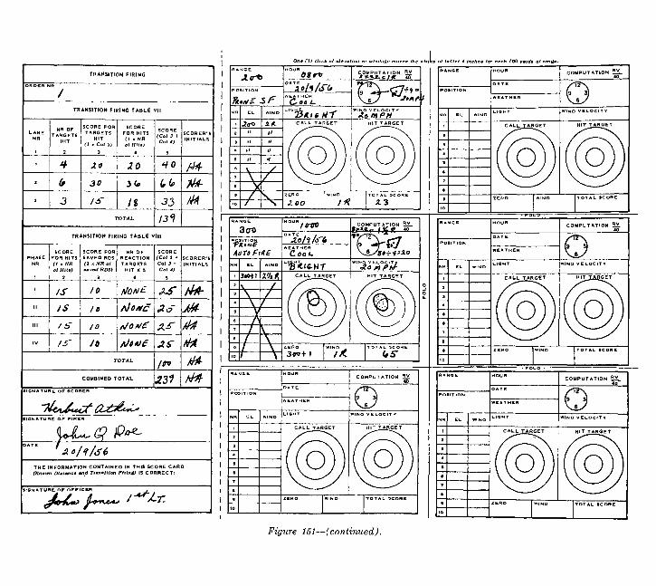
132. Use of the Firing Data Card
(Superseded)a. Keeping the Firing Data Card for Zeroing. The
automatic rifle is zeroed by firing three shot groups of three rounds each. Look at figure 152 @. This figure shows a block of firing data card filled out properly for zeroing. Notice all information to include the computation for the wind is present. The initial sight setting is entered opposite the first three shots since three round groups are fired before sight changes are made. After each shot is fired, the firer plots his call by placing the number of the shot on the call target. The target is marked after the three rounds have been fired. The exact location of the three shots are plotted by using the corresponding numbers and entering them on the hit target. A sight change is then made to move the shot group into the center of the bull's- eye. The change is figured from the center of the shot
TAGO 6587C—May 33
group. Once the change has been figured, the new sight setting is entered opposite the next three rounds and the process is completed until three shot groups have been fired. Notice that the call for shot number 5 is plotted in a corner of the call target with a question mark beside it. This indicates that the firer has flinched on the shot and could not call it. Also notice that when the target was marked, shot number 5 was a considerable distance from the other two shots of that group. For this reason, he ignored shot number 5 and computed his sight change based on the location of the other two shots of that group. After the third group has been fired, the firer then decides what his zero is, and enters this setting in the space provided. The zero of the automatic rifle for each range is that sight setting in elevation and windage which will cause the strike of the bullet to hit the center of the bull's-eye on a day when there is no wind. The last sight setting was 200 + 2 clicks eleva tion and 4 clicks right windage. Since 1 click of right windage was placed on the rear sight to correct for the wind, it must be taken off to determine the true zero of the automatic rifle. Therefore, the zero of the automatic rifle is 200 + 2 clicks elevation and 3 clicks right windage. The score is not totaled for zeroing so that block is crossed out.
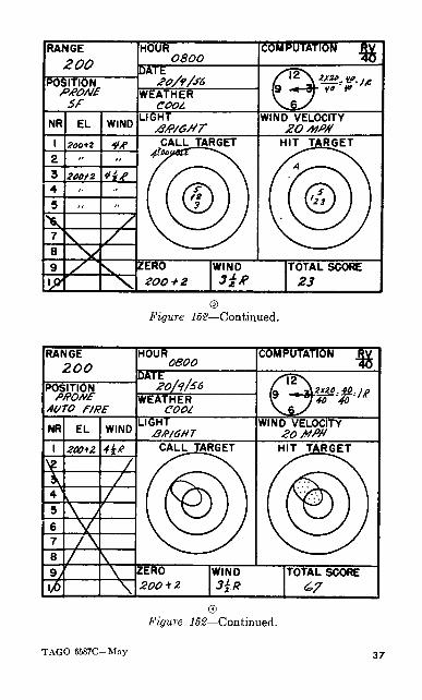
b. Keeping the Firing Data Card for Slow Fire. In figure 152 ® you see an example of how the firing data card is kept for slow fire. The sight setting in elevation and windage is entered opposite the first round and need not be entered for the remaining rounds providing no change is necessary. After each round is fired, the firer plots his call by entering the
34 TAGO 6587C—May
number of that shot on the call target at the location he thought it should strike. When the target is marked, he plots the exact location of the shot on the hit target using the corresponding number. After the second shot, the firer noted a slight change was neces sary so he made the correction and entered this cor rection opposite the third shot. Shot number four was a double and the firer could not call it accurately so he entered number four in the corner with a nota tion that it was a double. When all shots have been fired, he totals up the score from the hit target, and enters it in the space provided. His zero for that range is also entered in the space provided.
c. Keeping the Firing Data Card for Automatic Fire. In the recording block of figure 152 0, you see an example of how the firing data card is kept for
RANGE ZOO
POSITION
HOUR oeooPATE
20/1/S6WEATHER
COOL
COMPUTATION
NR EL WINDLIGHT WIND VELOCITY
20MPH200ZOO
CALL JARGET Sf
20OZOO+z 3R
200*1206*2
200+2
HIT Tj
too+z ZERO200 + 2
WIND 3*
TOTAL SCORE
© Figure 152—Continued!
TAGO 6587C—May 35
automatic fire. The sight setting is recorded only once since all rounds are fired with the same setting. After the exercise has been fired, the firer indicates where he thinks his group should be by drawing a circle on the call target. When the target is marked, he plots each shot on the hit target by using dots inside of a corresponding circle where his group hit the target. He then totals up his score from the hit target and enters it in the appropriate space on the firing data card.
d. Zero Record Card. The zero record card can be seen in the lower left hand corner of figure 151 ©. When the firer has completed zeroing his automatic rifle, he enters the sight settings in elevation and wind age for each range on this card. The card is then torn off at the perforation and pasted, glued, or shellacked onto the automatic rifle. The firer then has a ready reference to the zero sight settings for each range.
142. Firing Data Card
(Superseded)
The firing data card DA AGO Form 84 shown in figure 151 is recommended for use when firing any one of the five courses for record and practice. The firing data card is so designed as to carry the firer through his 1,000-inch instruction and record firing; through known distance instruction and record firing; and through transition zeroing, instruction and record fir ing. A record score card is provided which is detach able. Sample blocks are filled out to show you how the firing data card is filled out for the various courses of fire. Remember, the firing data card is not only a record of the firer, but also of the weapon.
36 TAGO 6587C—May
RANGE ZOO
POSITIONSf
HOUR _ O80O
DATE20/9/S6
WEATHER COOl
COMPUTATION
NR EL WIND LIGHT WIND VELOCITY
200+2
2OOt2
CALL TARGET
ZERO WIND 3**
TOTAL SCORE
Figure IBS—Continued.
RANGE 200
POSITION fl/?O/Vf
AUTO FIRE
HOUR0800
DATE
WEATHER COOt
COMPUTATION
NR EL WINDLIGHT WIND VELOCITY
200+Z
V/\
*t0 \
ZERO 200*2
WIND TOTAL SCORE
©Figure 152—Continued.
TAGO 6587C—May 37
Keep it accurately and completely. For detailed in structions on keeping the firing data card, see para graphs 131 and 132.
196. Functioning of the Operating Group
The introductory portion of this paragraph is re scinded.
6. Discuss the action * * * cartridge is fired. A chart on the gas system similar to figure 96 is very helpful in this instruction.
g. Explain that the ejector is stationary. During ejecting, the empty cartridge case strikes the receiver to the rear of the ejection opening and then rebounds to the right front.
;'. A chart similar to figure 94 is helpful in discuss ing chambering. Each instructional group discusses chambering using the automatic rifle, a magazine, and several dummy cartridges.
202. Set-Ups for Stoppages
c. Procedure. To present stoppages, demonstrate each stoppage as outlined below. Require various soldiers * * * for each stoppage.
38 TAGO 6587C—May
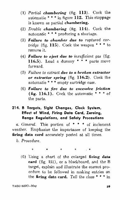
(1) Partial chambering (fig. 113). Cock the automatic * * * in figure 112. This stoppage is known as partial chambering.
(2) Double chambering (fig. 114). Cock the automatic * * * producing a shortage.
(3) Failure to chamber due to ruptured car tridge (fig. 115). Cock the weapon * * * to remove it.
(4) Failure to eject due to insufficient gas (fig. 116.5). Load a dummy * * * parts move forward.
(5) Failure to extract due to a broken extractor or extractor spring (fig. 116.2). Cock the automatic * * * empty cartridge case.
(6) Failure to fire due to excessive friction (fig. 116.1). Cock the automatic * * * of the parts.
214. B Targets, Sight Changes, Clock System, Effect of Wind, Firing Data Card, Zeroing, Range Regulations, and Safety Precautions
a. General. This portion of * * * of inclement weather. Emphasize the importance of keeping the firing data card accurately posted at all times.
b. Procedure.
(G) Using a chart of the enlarged firing data card (fig. 151), or a blackboard, and the B target, explain and illustrate the correct pro cedure to be followed in making entries on the firing data card. Tell the class * * * in
TAGO 6S87C—May 39
the target. Have each soldier solve several firing data card problems. Solve each prob lem using the firing data card chart. The stated velocity * * * of each problem. In clude in this discussion how to obtain the correct zero of the automatic rifle from the firing data card.
216. Range Orientation
6. Range firing is * * * the following subjects:
(6) The importance of keeping the firing data card accurately posted.
40 TAGO 6587C—May
[AG 474.2 (25 Mar 57)]
By Order of Wilber M. Bnicker, Secretary of the Army:
MAXWELL D. TAYLOR,General, United States Army,
Official:HERBERT M. JONES,
Major General, United Stales Army,The Adjutant General.
Chief of Staff.
Distribution:Active Army:
Tec Svc, DAAdmin & Tec Svc BdHq CONARCArmy AA ComdOS Maj ComdOS Base ComdLog ComdMDWArmiesCorpsDivBrigInf RegtArmor RegtInf Bn
Armor BnFt & CpDSMAGen & Br Svc SchPMST Sr Div Inf UnitMil DistMil MsnARMAUnits org under fol TOE:
7-2, Hq Co, Inf Div7-17, Inf R Co7-27, R Co, Armd Inf Bn7-37, Abn Inf R Co17-57, Recon Co57-57, Recon Co, Abn Div
NG: State AG; units—div; Inf Regt; Armor Regt; Inf Bn; Armor Bn. USAR: Div; Inf Regt; Armor Regt; Inf Bn; Armor Bn. For explanation of abbreviations used, see SR 320-50-1
TAGO 6587C—May
& U. S. GOVERNMENT PRINTING OFFICE: 1957—6OO643
41
DEPARTMENT OF THE ARMY FIELD MANUAL FM 23-15
This field manual supersedes FM 23-15, jo June 1943; including C I, 24 Decem ber 1943; C 2,6 March 1944; paragraph 10, Training Circular 10, Department of the Army, 20 July low; and Training Circular 7, Department of the Army, 21 April 1950.
BROWNING AUTOMATIC RIFLE
CALIBER .30 M1918A2
DEPARTMENT OF THE ARMY • JULY 1951
United States Government Printing Office Washington: 1951
DEPARTMENT OP THE ARMY WASHINGTON 25, D.C., 9 July 1951
FM 23-15 is published for the information and guidance of all concerned.[AG 474.2 (12 April 51)]
BY ORDER OF THE SECRETARY OP THE ARMY:
OFFICIAL: J. LAWTON COLLINS Wm. E. BERGIN Chief of Staff, Major General, USA United States Army Acting The Adjutant General
DISTRIBUTION :Tech Svc (2); Arm & Svc Bd (2); APP (25); AA
Comd (10); OS Maj Comd (15); Base Comd (5); MDW (5) ; Log Comd (5); A (20) ; CHQ (5); D (10); B (5); R 7, 17(10); Bn7, 17(6); PC (2); USMA (50); Sch (5); USA Mil Missions (1); US Army Missions (1); US Mil Att (1); T/O&E's; 7-2N (1); 7-17N (4); 7-27N (4); 7-37 (4); 17-57N (1); 17-77 (1).
For explanation of distribution formula, see SR 310-90-1.
CONTENTS
Paragraph PageCHAPTER 1. INTRODUCTION.......... 1-2 1
CHAPTER 2. MECHANICAL TRAININGSection I. General................. 3-5 ' 2
II. Disassembly and assembly. 6-20 6III. Functioning.............. 21-42 88IV. Operation............... 43-54 115
V. Stoppages and immediateaction. ................ 55-60 132
VI. Care and cleaning........ 61-71 143VII. Spare parts and accessories. 72-73 158
VIII. Ammunition............. 74-83 163
CHAPTER 3. MARKSMANSHIP TRAININGSection I. General.................. 84-86 172
//. Preparatory marksmanshiptraining............... 87-133 175
///. Courses and score cards... 134-142 279 IV. Range firing. ............ 143-161 308
V. Equipment, targets andranges................ 162-164 338
CHAPTER 4. MARKSMANSHIP, MOVING GROUND AND AERIAL TARGETS
Section I. General................. 165-167 344II. Moving personnel. ....... 168-169 345
III. Moving vehicles. ......... 170-171 34877. Aerial targets............ 172-173 349
CHAPTER 5. TECHNIQUE OF FIRE AND DESTRUCTION OF MATERIEL
Section I. Technique of fire. ........ 174-176 352II. Destruction of ordnance
materiel in event of im minent capture. ........ 177-179 353
Paragraph PageCHAPTER 6. ADVICE TO INSTRUCTORS
Section I. General................. 180-184 356//. Subject schedule, auto
matic rifle marksman ship course. ........... 185-188 360
///. Subject schedule, auto- m;atic rifle familiariza tion course............ 189-192 384
IV. Advice to instructors—mechanical training. .... 193-204 392
V. Advice to instructors— preparatory marksman ship training........... 205-222 407
VI. Training aids............ 223-230 441
CHAPTER 7. SAFETY PRECAUTIONS-... 231-235 464
APPENDIX REFERENCES................. ....... 470
INDEX................................... ........ 475
iv
RESTRICTED
This field manual supersedes FM 23-15, 30 June 1943; including C 1, 24 December 1943; C 2, 6 March 1944; paragraph 10, Training Circular 10, Department of the Army, 20 July 1949; and Training Circular 7, Department of the Army, 21 April 1950.
CHAPTER 1
INTRODUCTION
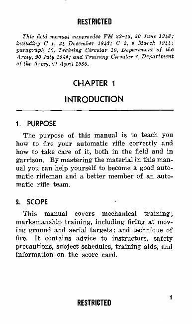
1. PURPOSEThe purpose of this manual is to teach you
how to fire your automatic rifle correctly and how to take care of it, both in the field and in garrison. By mastering the material in this man ual you can help yourself to become a good auto matic rifleman and a better member of an auto matic rifle team.
2. SCOPE
This manual covers mechanical training; marksmanship training, including firing at mov ing ground and aerial targets; and technique of fire. It contains advice to instructors, safety precautions, subject schedules, training aids, and information on the score card.
RESTRICTED
CHAPTER 2
MECHANICAL TRAINING
Section I. GENERAL
3. PURPOSE OF MECHANICAL TRAINING
This chapter teaches you how to disassemble and assemble the four main groups of working parts that make up your automatic rifle. It also tells you how each group of moving parts works and how you can keep your automatic rifle in good firing condition. You must have a thorough knowledge of the mechanical parts of your auto matic rifle. You will need this knowledge on the firing range and on the battlefield. When you learn how to disassemble and assemble your auto matic rifle, you will be able to clean it and care for it properly. The importance of care and cleaning cannot be overstressed; proper care and cleaning will prevent many stoppages. When you learn the mechanical parts of your automatic rifle and understand how they work, you can lo cate quickly the cause of any trouble your rifle may develop and you will know how to correct it.
4. GENERAL DESCRIPTION OF THE RIFLE
a. The Browning Automatic Rifle, Caliber .30, M1918A2, is one of the world's best automatic rifles. Treat it with the care and respect it de-2
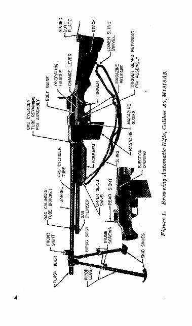
serves and it will produce for you the desired com bat results. It is an air cooled, gas operated, magazine fed, shoulder type weapon with a bi pod (fig. 1). The magazine is box type and holds 20 rounds.
b. The automatic rifle is equipped with front and rear sights. The front sight is stationary but the rear sight can be moved up or down and to the left or right. You turn the elevating knob to raise or lower the sight when you want the bul let to strike higher or lower on the target. The elevation scale on the rear sight of most automatic rifles can be set as low as 100 yards. On some older models, however, the' elevation scale can be lowered only to 300'yards. When the wind is strong enough to blow a bullet off its course, you turn the windage knob to move the rear sight to the right or left. Changing the windage adjust ment causes the strike of succeeding bullets on the target to be moved in the same direction (right or left) that the sight was moved.
c. Examine your automatic rifle to make sure that it is riot loaded. Look down the barrel and you will see spiral grooves cut in the bore. The ribs that stand out between the grooves are called the lands. The grooves and lands make one com plete turn in 10 inches of barrel length. The grodves and lands are called rifling. The rifling makes the bullet rotate and keeps it from tum bling in flight. This causes it to follow a uniform course to the target.
GAS
C
YLIN
DER
TU
BE R
ETAI
NIN
G
PIN
AS
SEM
BLY
STO
CK
LOW
ER
SLI
NG
S
WIV
EL
TRIG
GER
G
UARD
RE
TAIN
ING
PI
N
ASSE
MBL
Y
Fig
ure
1.
Bro
wni
ng A
utom
atic
Rifl
e, C
alib
er .3
0, M
1918
A2.
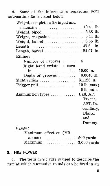
d. Some of the information regarding your automatic rifle is listed below.
Weight, complete with bipod and magazine ..................... 19.4 Ib.
Weight, bipod ......'............. 2.38 Ib.Weight, magazine ............... 0.44 Ib.Weight, barrel .................. 3.65 Ib.Length ......................... 47.8 in.Length, barrel ................. .24.07 in.Rifling:
Number of grooves ...... 4Right hand twist: 1 turn
in .................:.. 10.00 in.Depth of grooves ........ 0.0040 in.
Sight radius ................. 31.125 in.Trigger pull ................. 10 Ib. max;
6 Ib. min. Ammunition types ............ Ball, AP,
Tracer, API, In cendiary, Blank, andDummy.
Range:Maximum effective (M2
ammo) ............... 500 yardsMaximum ............... 3,000 yards
5. FIRE POWER
a. The term cyclic rate is used to describe the rate at which successive rounds can be fired in an
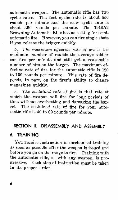
automatic weapon. The automatic rifle has two cyclic rates. The fast cyclic rate is about 550 rounds per minute and the slow cyclic rate is about 350 rounds per minute. The 1918A2 Browning Automatic Rifle has no setting for semi automatic fire. However, you can fire single shots if you release the trigger quickly.
6. The maximum effective rate of fire is the maximum number of rounds the average soldier can fire per minute and still get a reasonable number of hits on the target. The maximum ef fective rate of fire for the automatic rifle is 120 to 150 rounds per minute. This rate of fire de pends, in part, on the firer's ability to change magazines quickly.
c. The sustained rate of fire is that rate at which the weapon will fire for long periods of time without overheating and damaging the bar rel. The sustained rate of fire for your auto matic rifle is 40 to 60 rounds per minute.
SECTION II. DISASSEMBLY AND ASSEMBLY
6. TRAINING
You receive instruction in mechanical training as soon as possible after the weapon is issued and before you go on the range to fire. Training with the automatic rifle, as with any weapon, is pro gressive. Each step of instruction must be taken in its proper order.
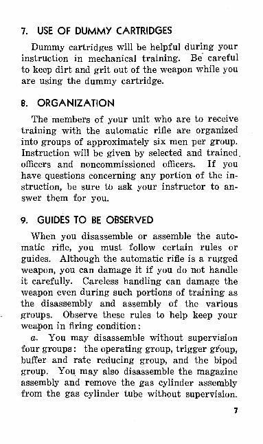
7. USE OF DUMMY CARTRIDGES
Dummy cartridges will be helpful during your instruction in mechanical training. Be careful to keep dirt and grit out of the weapon while you are using the dummy cartridge.
8. ORGANIZATION
The members of your unit who are to receive training with the automatic rifle are organized into groups of approximately six men per group. Instruction will be given by selected and trained, officers and noncommissioned officers. If you have questions concerning any portion of the in struction, be sure to ask your instructor to an swer them for you.
9. GUIDES TO BE OBSERVED
When you disassemble or assemble the auto matic rifle, you must follow certain rules or guides. Although the automatic rifle is a rugged weapon, you can damage it if you do not handle it carefully. Careless handling can damage the weapon even during such portions of training as the disassembly and assembly of the various groups. Observe these rules to help keep your weapon in firing condition:
a. You may disassemble without supervision four groups: the operating group, trigger group, buffer and rate reducing group, and the bipod group. You may also disassemble the magazine assembly and remove the gas cylinder assembly from the gas cylinder tube without supervision.
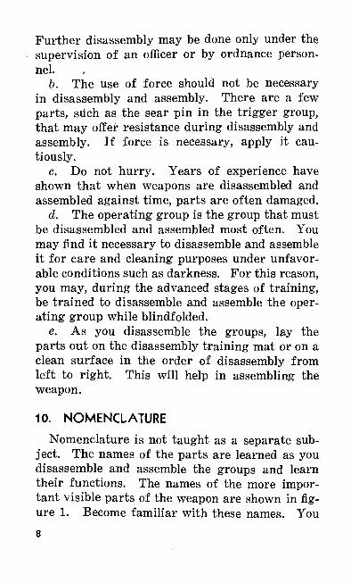
Further disassembly may be done only under the supervision of an officer or by ordnance person nel.
b. The use of force should not be necessary in disassembly and assembly. There are a few parts, such as the sear pin in the trigger group, that may offer resistance during disassembly and assembly. If force is necessary, apply it cau tiously.
c. Do not hurry. Years of experience have shown that when weapons are disassembled and assembled against time, parts are often damaged.
d. The operating group is the group that must be disassembled and assembled most often. You may find it necessary to disassemble and assemble it for care and cleaning purposes under unfavor able conditions such as darkness. For this reason, you may, during the advanced stages of training, be trained to disassemble and assemble the oper ating group while blindfolded.
e. As you disassemble the groups, lay the parts out on the disassembly training mat or on a clean surface in the order of disassembly from left to right. This will help in assembling the weapon.
10. NOMENCLATURE
Nomenclature is not taught as a separate sub ject. The names of the parts are learned as you disassemble and assemble the groups and learn their functions. The names of the more impor tant visible parts of the weapon are shown in fig ure 1. Become familiar with these names. You8
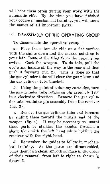
will hear them often during your work with the automatic rifle. By the time you have finished your course in mechanical training, you will know the names of all important parts.
11. DISASSEMBLY OF THE OPERATING GROUP
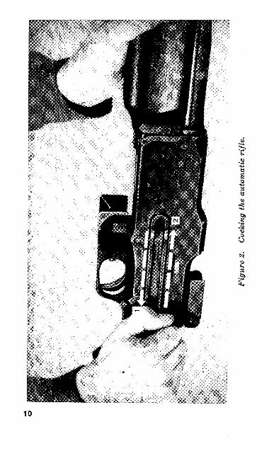
To disassemble the operating group—a. Place the automatic rifle on a flat surface
with the sights down and the muzzle pointing to your left. Remove the sling from the upper sling swivel. Cock the weapon. To do this, pull the operating handle all the way to the rear and then push it forward (fig. 2). This is done so that the gas cylinder tube will clear the gas piston and the gas cylinder tube bracket.
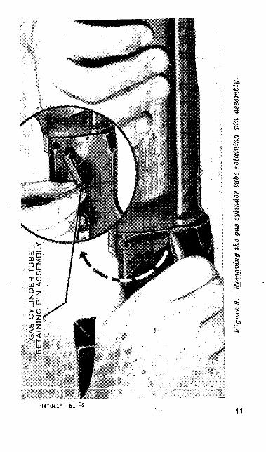
6. Using the point of a dummy cartridge, turn the gas-cylinder tube retaining pin assembly 180° in a clockwise direction. Remove the gas cylin der tube retaining pin assembly from the receiver (fig- 3).
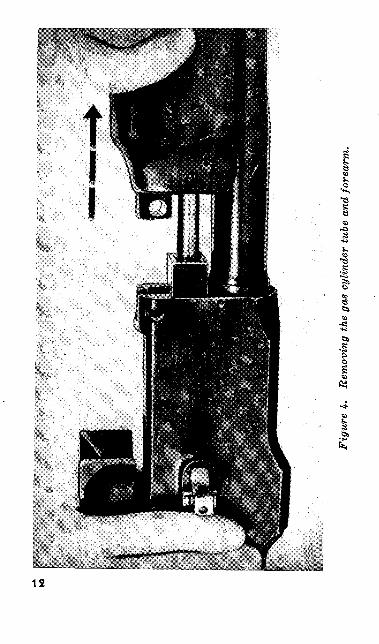
c. Remove the gas cylinder tube and forearm by sliding them toward the muzzle end of the weapon (fig. 4). It may be necessary to unseat these parts by striking the wooden forearm a sharp blow with the left hand while holding the receiver with the right hand.
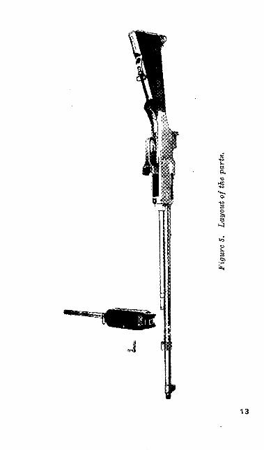
d. Remember the guides to follow in mechan ical training. As the parts are disassembled, place them on a clean, smooth surface in the order of their removal, from left to right as shown in figure 5.
Fig
ure
2.
Coc
king
the
aut
omat
ic r
ifle.
JGA
S C
YLIN
DE
R T
UB
E
RE
TA
ININ
G P
IN A
SS
EM
BLY
Fig
ure
3.
Rem
ovin
g th
e ga
s cy
lin
der
tube
ret
ain
ing
pin
ass
embl
y.
Fig
ure
4-
Rem
ovin
g th
e ga
s cy
linde
r tu
be a
nd fo
rear
m.
O Si 8
1;-
13
Figu
re 6
. Al
low
ing
the
oper
atin
g pa
rts
to g
o fo
rwar
d.
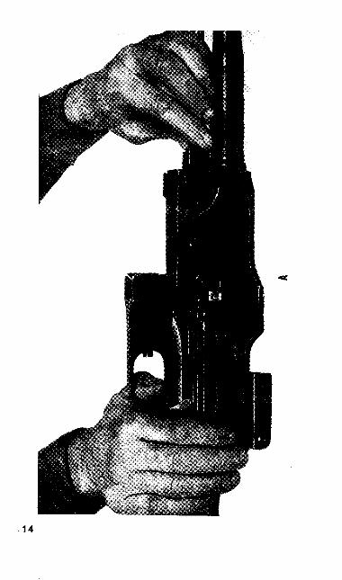
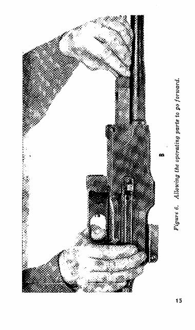
e. Before further disassembly, the operating parts must be moved forward. Grasp the slide between the fingers of the left hand (A of fig. 6). Press the trigger with the right thumb and allow the operating parts to move forward slowly (B of fig. 6). Be careful that the piston rings are not burred by striking the gas cylinder tube bracket as the parts go forward.
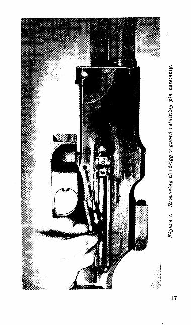
/. Using the point of a dummy cartridge, ro tate the trigger guard retaining pin assembly 90° clockwise. Remove the trigger guard retaining pin assembly (fig. 7).
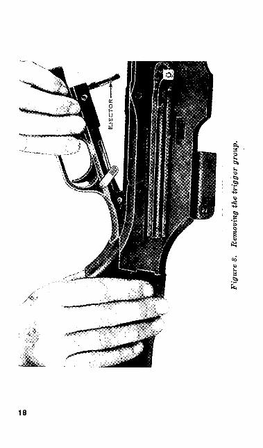
g. Lift out the trigger group (fig. 8). Place it on the table' with the ejector pointing upward. The trigger group is placed on the table this way so that the trigger pin will not fall out.
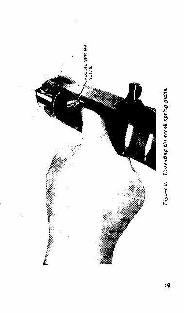
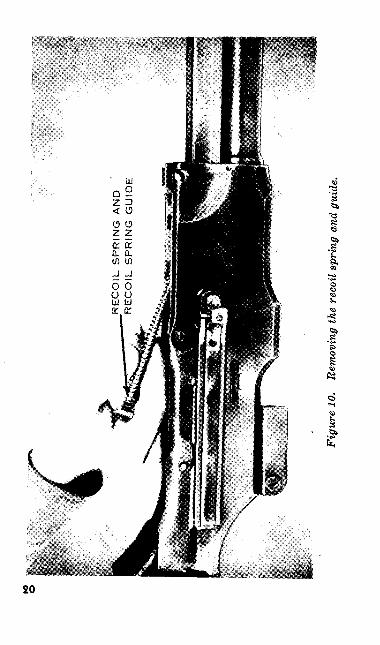
h. The next parts to be removed are the, re coil spring and recoil spring guide. Grasp the slide with the left hand, palm down. Press on the checkered surface of the recoil spring guide with the right index finger (fig. 9). Turn the recoil spring guide until its ends are clear of the retain ing shoulders in the forward end of the receiver. Allow the recoil spring to expand slowly. Re move the recoil spring and recoil spring guide to the rear (fig. 10). Separate the two parts.
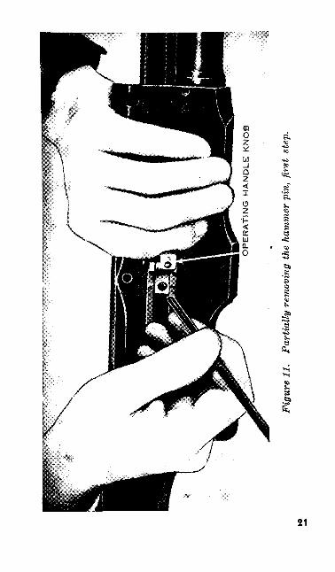
i. Before removing the operating handle, partially remove the hammer pin. To do this, grasp the receiver with the left hand, palm down, with the left forefinger placed against the knob of the operating handle (fig. 11). With the slide fully forward, insert the point of the recoil spring guide in the hole of the operating handle and16
Fig
ure
7.
Rem
ovin
g th
e tr
igge
r gu
ard
reta
inin
g pi
n as
sem
bly.
Fig
ure
8.
Rem
ovin
g th
e tr
igge
r gr
oup.
RE
CO
IL S
PR
ING
G
UID
E
Figu
re 9
. U
nsea
ting
the
reco
il sp
ring
gui
de.
to o
RE
CO
IL S
PR
ING
A
ND
R
EC
OIL
SP
RIN
G G
UID
E
Figu
re 1
0.
Rem
ovin
g th
e re
coil
spri
ng a
nd g
uide
.
OP
ER
AT
ING
H
AN
DL
E
KN
OB
Fig
ure
11.
Par
tially
rem
ovin
g th
e ha
mm
er p
in,
first
ste
p.
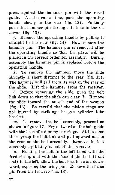
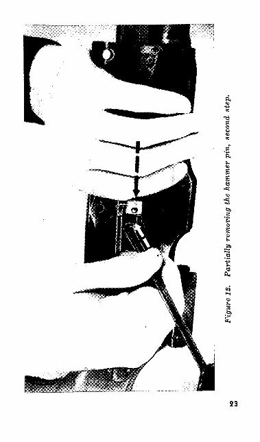
press against the hammer pin with the recoil guide. At the same time, push the operating handle slowly to the rear (fig. 12). Partially push the hammer pin through its hole in the re ceiver (fig. 13).
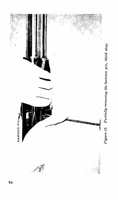
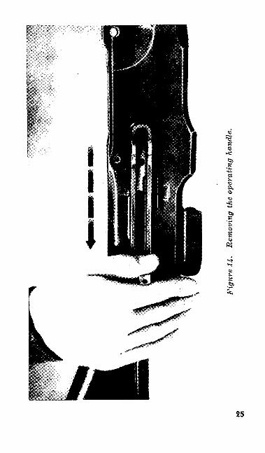
j. Remove the operating handle by pulling it straight to the rear (fig. 14). Now remove the hammer pin. The hammer pin is removed after the operating handle so that the parts will be placed in the correct order for assembly. During assembly the hammer pin is replaced before the operating handle.
k. To remove the hammer, move the slide abruptly a short distance to the rear (fig. 15). The hammer will fall from its seat in the rear of the slide. Lift the hammer from the receiver.
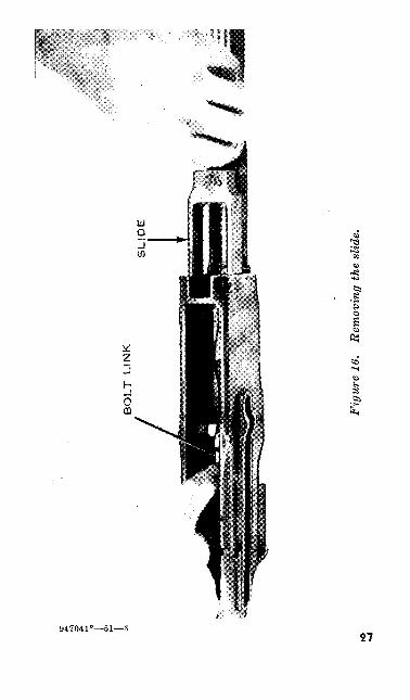
I. Before removing the slide, push the bolt link down so that the slide can clear it. Remove the slide toward the muzzle end of the weapon (fig. 16). Be careful that the piston rings are not burred by striking the gas cylinder tube bracket.
TO. To remove the bolt assembly, proceed as shown in figure 17. Pry outward on the bolt guide with the base of a dummy cartridge. At the same time, grasp the bolt link and pull upward and to the rear on the bolt assembly. Remove the bolt assembly by lifting it out of the receiver.
n. Holding the bolt in the left hand with the feed rib up and with the face of the bolt (front end) to the left, allow the bolt lock to swing down ward, exposing the firing pin. Remove the firing pin from the feed rib (fig. 18).22
K5
U>
Fig
ure
12.
Par
tially
rem
ovin
g th
e ha
mm
er p
in,
seco
nd s
tep.
§•
.8s.
s-si
I
24
Fig
ure
14.
Rem
ovin
g th
e op
erat
ing
hand
le.
10 t/l
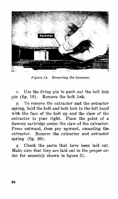
Figure 15. Removing the hammer.
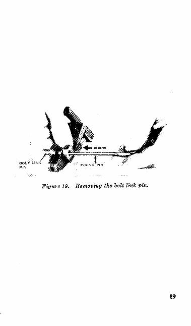
o. Use the firing pin to push out the bolt link pin (fig. 19). Remove the bolt link.
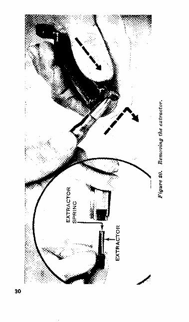
p. To remove the extractor and the extractor spring, hold the bolt and bolt lock in the left hand with the face of the bolt up and the claw of the extractor to your right. Place the point of a dummy cartridge under the claw of the extractor. Press outward, then pry upward, unseating the extractor. Remove the extractor and extractor spring (fig. 20).
q. Check the parts that have been laid out. Make sure that they are laid out in the proper or der for assembly shown in figure 21.
26
Fig
ure
16.
Rem
ovin
g th
e sl
ide.
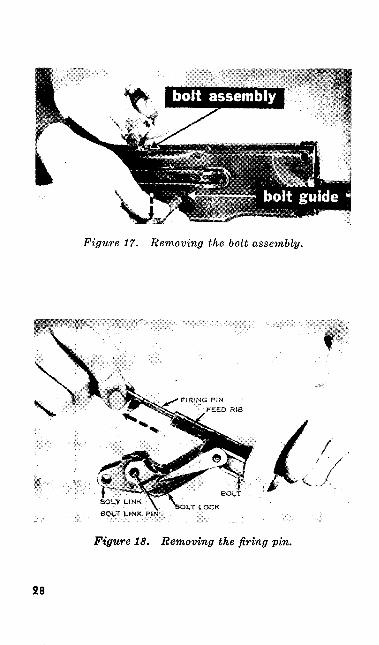
Figure 17. Removing the bolt assembly.
BOLT LINK
BOLT LINK PIN
Figure 18. Removing the firing pin.
28
BOLT LINK P!N
Figure 19. Removing the bolt link pin.
29
Fig
ure
20.
Rem
ovin
g th
e ex
trac
tor.
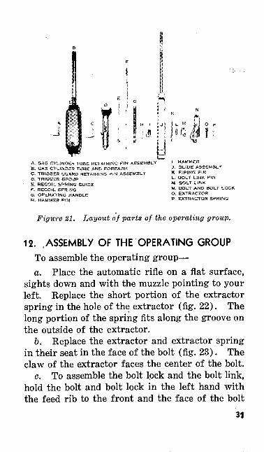
A, GAS CYLINDER TUBE RETAINING PIN AB. GAS CYLINDER TlJSE AND FOREARMC. TRIGGER GUARD RETAINING PIN ASSEMBLYO, TRIGGER GROUPS, RECOIL SPRING GUIDEF. RECOIL SPRING<3, OPERATING HANDLEH, HAMMER PtN
!. HAMMERJ. SLIDE ASSEMBLYK, FIRING PINt,. BOLT LINK PINM, SQLT UNKN. BOLT AND BOLT LOCKO, EXTRACTORP, EXTRACTOR SPRING
Figure 21. Layout of parts of the operating group.
12. .ASSEMBLY OF THE OPERATING GROUP
To assemble the operating group—a. Place the automatic rifle on a flat surface,
sights down and with the muzzle pointing to your left. Replace the short portion of the extractor spring in the hole of the extractor (fig. 22). The long portion of the spring fits along the groove on the outside of the extractor.
b. Replace the extractor and extractor spring in their seat in the face of the bolt (fig. 23). The claw of the extractor faces the center of the bolt.
c. To assemble the bolt lock and the bolt link, hold the bolt and bolt lock in the left hand with the feed rib to the front and the face of the bolt
31
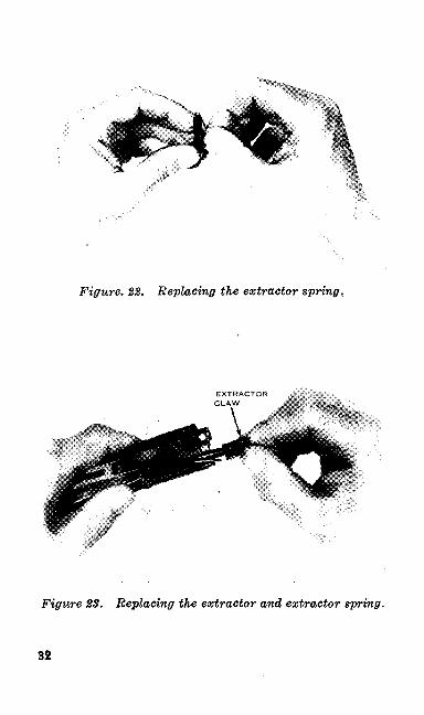
Figure. 2%. Replacing the extractor spring.
EXTRACTOR CLAW
Figure 83. Replacing the extractor and extractor spring.
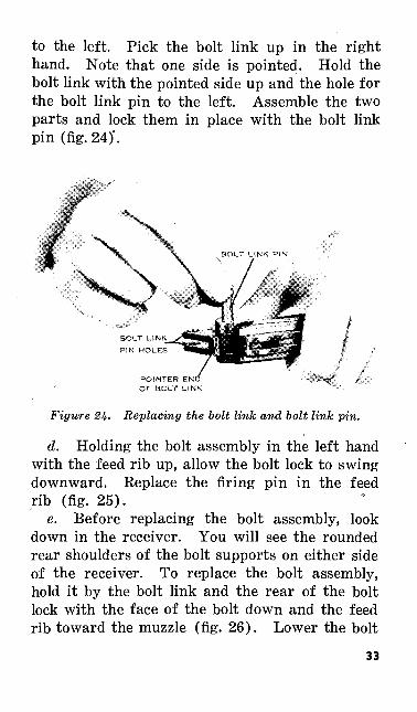
to the left. Pick the bolt link up in the right hand. Note that one side is pointed. Hold the bolt link with the pointed side up and the hole for the bolt link pin to the left. Assemble the two parts and lock them in place with the bolt link pin (fig. 24)'.
POINTER EN OF BOLT LINK
Figure 26. Replacing the bolt link and bolt link pin.
d. Holding the bolt assembly in the left hand with the feed rib up, allow the bolt lock to swing downward. Replace the firing pin in the feed rib (fig. 25).
e. Before replacing the bolt assembly, look down in the receiver. You will see the rounded rear shoulders of the bolt supports on either side of the receiver. To replace the bolt assembly, hold it by the bolt link and the rear of the bolt lock with the face of the bolt down and the feed rib toward the muzzle (fig. 26). Lower the bolt
33
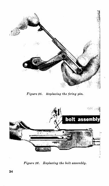
Figure 25. Replacing the firing pin.
Figure 26. Replacing the bolt assembly.
34
Figu
re 2
7.
Repl
acin
g th
e sli
de.
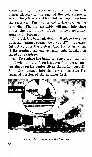
assembly into the receiver so that the feed rib passes directly to the rear of the bolt supports. Allow the bolt lock and bolt link to drop down into the receiver. Push down and to the rear on the feed rib. The bolt assembly will snap into place under the bolt guide. Push the bolt assembly completely forward.
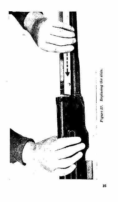
/. Push the bolt link down. Replace the slide with the hammer recess down (fig. 27). Be care ful not to burr the piston rings by letting them strike against the gas cylinder tube bracket as the slide is replaced.
g. To replace the hammer, grasp it in the left hand with the thumb on the large flat surface and forefinger on the center rib as shown in figure 28. Slide the hammer into the recess, inserting the rounded portion of the hammer first.
Figure 28. Replacing the hammer.
36
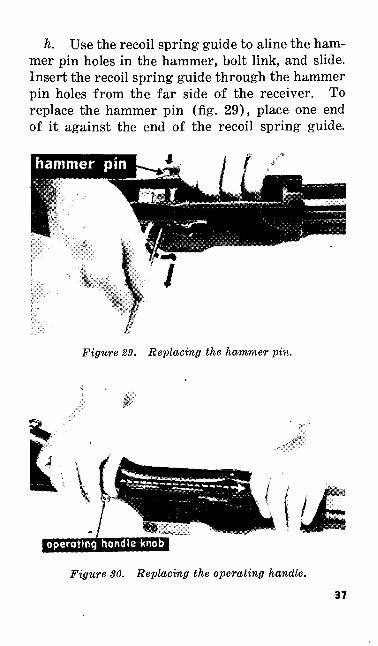
h. Use the recoil spring guide to aline the ham mer pin holes in the hammer, bolt link, and slide. Insert the recoil spring guide through the hammer pin holes from the far side of the receiver. To replace the hammer pin (fig. 29), place one end of it against the end of the recoil spring guide.
Figure 29. Replacing the hammer pin.
operating handle knob
Figure 30. Replacing the operating handle.
37
Push in on the hammer pin and at the same time remove the recoil spring guide with a slow circu lar motion. This action will keep the hammer pin holes alined as the hammer pin is inserted. Do not replace the hammer pin completely.
i. Replace the operating handle (fig. 30). The operating handle knob must be toward the muzzle end of the weapon. As soon as the operating handle is replaced, push in the hammer pin all the way.
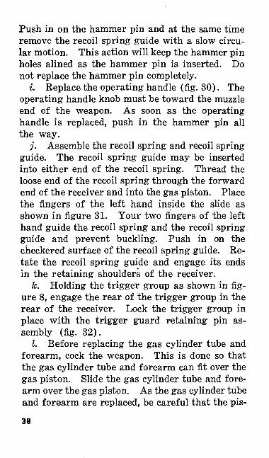
j. Assemble the recoil spring and recoil spring guide. The recoil spring guide may be inserted into either end of the recoil spring. Thread the loose end of the recoil spring through the forward end of the receiver and into the gas piston. Place the fingers of the left hand inside the slide as shown in figure 31. Your two fingers of the left hand guide the recoil spring and the recoil spring guide and prevent buckling. Push in on the checkered surface of the recoil spring guide. Ro tate the recoil spring guide and engage its ends in the retaining shoulders of the receiver.
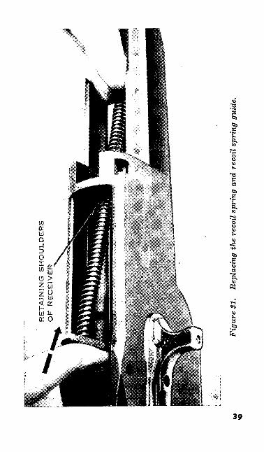
fc. Holding the trigger group as shown in fig ure 8, engage the rear of the trigger group in the rear of the receiver. Lock the trigger group in place with the trigger guard retaining pin as sembly (fig. 32).
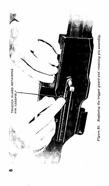
I. Before replacing the gas cylinder tube and forearm, cock the weapon. This is done so that the gas cylinder tube and forearm can fit over the gas piston. Slide the gas cylinder tube and fore arm over the gas piston. As the gas cylinder tube and forearm are replaced, be careful that the pis-
38
RE
TA
ININ
G S
HO
ULD
ER
S
OP
R
EC
EIV
ER
<*»
<OFi
gure
SI.
Repl
acin
g th
e re
coil
spri
ng a
nd r
ecoi
l spr
ing
guid
e.
TR
IGG
ER
G
UA
RD
R
ET
AIN
ING
P
IN
AS
SE
MB
LY
Fig
ure
S2.
Repl
acin
g th
e tr
igge
r gu
ard
and
reta
inin
g pi
n as
sem
bly.
1 ;
GA
S C
YL
IND
ER
T
UB
ER
ET
AIN
ING
PIN
A
SS
EM
BL
Y
Fig
ure
33.
Repl
acin
g th
e ga
s cy
linde
r tu
be r
etai
ning
pin
ass
embl
y.
ton rings on the gas piston are not burred. Lock the gas cylinder tube and forearm in place with the gas cylinder tube retaining pin assembly (fig. 33).
13. DISASSEMBLY OF THE TRIGGER GROUP
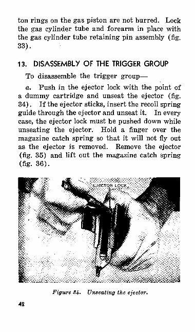
To disassemble the trigger group—a. Push in the ejector lock with the point of
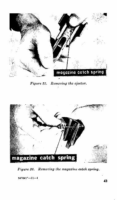
a dummy cartridge and unseat the ejector (fig. 34). If the ejector sticks, insert the recoil spring guide through the ejector and unseat it. In every case, the ejector lock must be pushed down while unseating the ejector. Hold a finger over the magazine catch spring so that it will not fly out as the ejector is removed. Remove the ejector (fig. 35) and lift out the magazine catch spring (fig. 36).
Figure 34. Unseating the ejector.
42
magazine catch spring
Figure 35. Removing the ejector.
Figure 86. Removing the magazine catch spring.
947041°—51—143
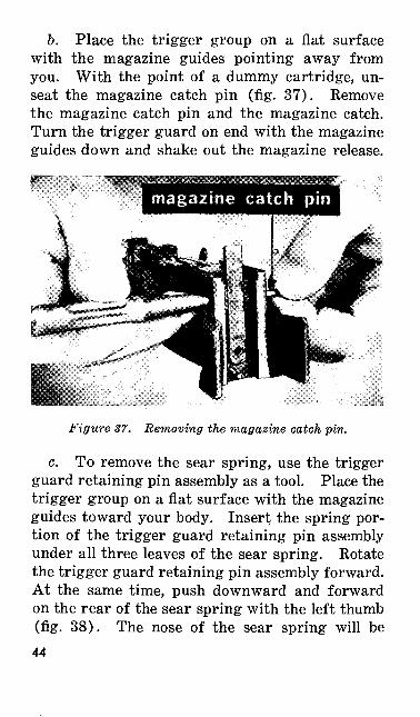
b. Place the trigger group on a flat surface with the magazine guides pointing away from you. With the point of a dummy cartridge, un seat the magazine catch pin (fig. 37). Remove the magazine catch pin and the magazine catch. Turn the trigger guard on end with the magazine guides down and shake out the magazine release.
magazine catch pin
Figure 37. Removing the magazine catch pin.
c. To remove the sear spring, use the trigger guard retaining pin assembly as a tool. Place the trigger group on a flat surface with the magazine guides toward your body. Insert the spring por tion of the trigger guard retaining pin assembly under all three leaves of the sear spring. Rotate the trigger guard retaining pin assembly forward. At the same time, push downward and forward on the rear of the sear spring with the left thumb (fig. 38). The nose of the sear spring will be44
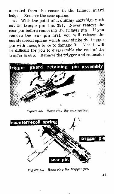
unseated from the recess in the trigger guard ledge. Remove the sear spring.
d. With the point of a dummy cartridge push out the trigger pin (fig. 39). Never remove the sear pin before removing the trigger pin. If you remove the sear pin first, you will release the counterrecoil spring which may strike the trigger pin with enough force to damage it. Also, it will be difficult for you to disassemble the rest of the trigger group. Remove the trigger and connector
Figure 38. Removing the sear spring.
~\
' j
Figure 39. Removing the trigger pin.
connector
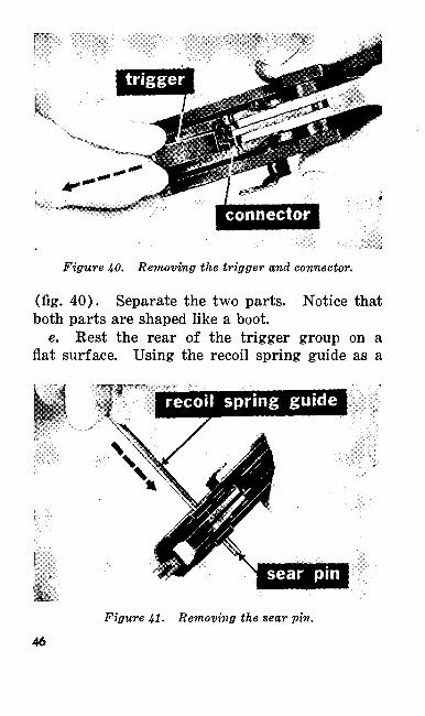
Figure 40. Removing the trigger and connector.
(fig. 40). Separate the two parts. Notice that both parts are shaped like a boot.
e. Rest the rear of the trigger group on a flat surface. Using the recoil spring guide as a
recoil spring guide
Figure 41. Removing the sear pin.
46
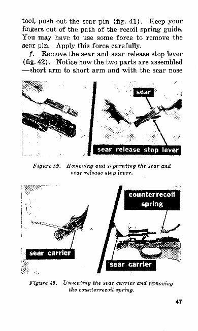
tool, push out the sear pin (fig. 41). Keep your fingers out of the path of the recoil spring guide. You may have to use some force to remove the sear pin. Apply this force carefully.
/. Remove the sear and sear release stop lever (fig. 42). Notice how the two parts are assembled —short arm to short arm and with the sear nose
Figure 42.
sear release stop lever
Removing and separating the sear and sear release stop lever.
counterrecoil
Figure 43. Unseating the sear carrier and removing the counterrecoil spring.
47
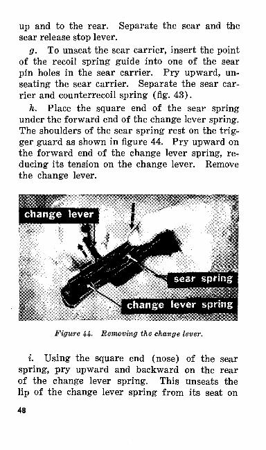
up and to the rear. Separate the sear and the sear release stop lever.
g. To unseat the sear carrier, insert the point of the recoil spring guide into one of the sear pin holes in the sear carrier. Pry upward, un seating the sear carrier. Separate the sear car rier and counterrecoil spring (fig. 43).
h. Place the square end of the sear spring under the forward end of the change lever spring. The shoulders of the sear spring rest on the trig ger guard as shown in figure 44. Pry upward on the forward end of the change lever spring, re ducing its tension on the change lever. Remove the change lever.
Figure 44. Removing the change lever.
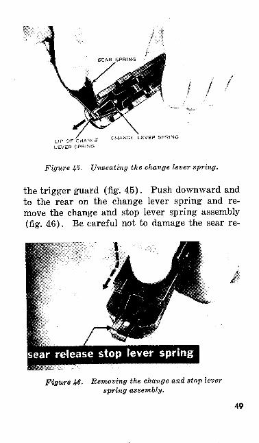
i. Using the square end (nose) of the sear spring, pry upward and backward on the rear of the change lever spring. This unseats the lip of the change lever spring from its seat on
48
LIP OF CHANC-.F LEVER 'SPf^NG
CHANGE LEVER SPRING
Figure 45. Unseating the change lever spring.
the trigger guard (fig. 45). Push downward and to the rear on the change lever spring and re move the change and stop lever spring assembly (fig. 46). Be careful not to damage the sear re-
Figure 46. Removing the change and stop lever spring assembly.
49
01 o
fiO
E
A
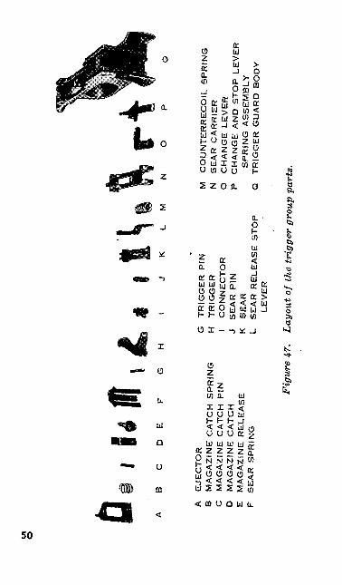
EJE
CT
OR
B
MA
GA
ZIN
E C
AT
CH
SP
RIN
GC
M
AG
AZ
INE
CA
TC
H
PIN
D
MA
GA
ZIN
E C
AT
CH
E M
AG
AZI
NE
RE
LE
ASE
F
SE
AR
SP
RIN
G
G
TR
IGG
ER
P
IN
M
H
TR
IGG
ER
N
I
CO
NN
EC
TO
R
O
J S
EA
R P
IN
P
K
SE
AR
L SE
AR
RE
LE
ASE
ST
OP
Q
LEV
ER
CO
UN
TE
RR
EC
OIL
SP
RIN
G
SE
AR
CA
RR
IER
C
HA
NG
E L
EV
ER
C
HA
NG
E A
ND
S
TO
P L
EV
ER
SP
RIN
G A
SS
EM
BLY
T
RIG
GE
R G
UA
RD
B
OD
Y
Fig
ure
47.
Layo
ut o
f the
tri
gger
gro
up p
arts
.
lease stop lever spring during this step. Apply pressure to the rear of the stud connecting the change lever spring and sear release stop lever spring.
j. Check the parts that have been laid out. Make sure that they are laid out in the proper order for assembly shown in figure 47.
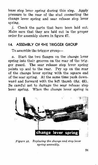
14. ASSEMBLY OF-THE TRIGGER GROUP
To assemble the trigger group—a. Start the two flanges on the change lever
spring into their grooves on the rear of the trig ger guard. The sear release stop lever spring points up and to the rear. Pry up on the rear of the change lever spring with the square end of the sear spring. At the same time push down ward and forward with the left thumb (fig. 48). Be careful not to damage the sear release stop lever spring. When the change lever spring is
Figure 48.
change lever spring
Replacing the change and stop level- spring assembly.
51
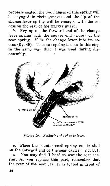
properly seated, the two flanges of this spring will be engaged in their grooves and the lip of the change lever spring will be engaged with the re cess on the rear of the trigger guard.
b. Pry up on the forward end of the change lever spring with the square end (nose) of the sear spring. Slide the change lever into its re cess (fig. 49). The sear spring is used in this step in the same way that it was used during dis assembly.
1
CHANGE AND STOP LEVER SPRING ASSEMBLY
Figure 49. Replacing the change lever.
c. Place the counterrecoil spring on its stud on the forward end of the sear carrier (fig. 50).
d. You may find it hard to seat the sear car rier. As you replace this part, remember that the rear of the sear carrier is seated in front of52
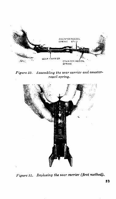
.**».
COUNTER RECOIL SPRING
Figure 50. Assembling the sear carrier and counter- recoil spring.
Figure 51. Replacing the sear carrier (first method).
53
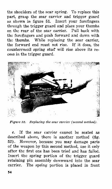
the shoulders of the sear spring. To replace this part, grasp the sear carrier and trigger guard as shown in figure 51. Insert your forefingers through the trigger guard and place your thumbs on the rear of the sear carrier. Pull back with the forefingers and push forward and down with the thumbs. While replacing the sear carrier, the forward end must not rise. If it does, the counterrecoil spring stud* will rise above its re cess in the trigger guard.
Figure 52. Replacing the sear carrier (second method).
e. If the sear carrier cannot be seated as described above, there is another method (fig. 52). However, because you may damage parts of the weapon by this second method, use it only after the first one has been tried and has failed. Insert the spring portion of the trigger guard retaining pin assembly downward into the sear carrier. The spring portion is placed in front54
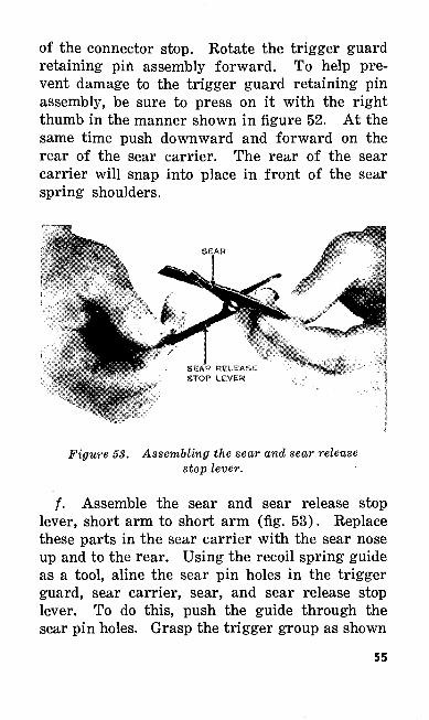
of the connector stop. Rotate the trigger guard retaining pin assembly forward. To help pre vent damage to the trigger guard retaining pin assembly, be sure to press on it with the right thumb in the manner shown in figure 52. At the same time push downward and forward on the rear of the sear carrier. The rear of the sear carrier will snap into place in front of the sear spring shoulders.
Figure 53. Assembling the sear and sear release stop lever.
f. Assemble the sear and sear release stop lever, short arm to short arm (fig. 53). Replace these parts in the sear carrier with the sear nose up and to the rear. Using the recoil spring guide as a tool, aline the sear pin holes in the trigger guard, sear carrier, sear, and sear release stop lever. To do this, push the guide through the sear pin holes. Grasp the trigger group as shown
55
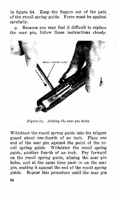
in figure 54. Keep the fingers out of the path of the recoil spring guide. Force must be applied carefully.
g. Because you may find it difficult to replace the sear pin, follow these instructions closely.
Figure 54- Alining the sear pin holes.
Withdraw the recoil spring guide into the trigger guard about one-fourth of an inch. Place one end of the sear pin against the point of the re coil spring guide. Withdraw the recoil spring guide, another fourth of an inch. Pry forward on the recoil spring guide, alining the sear pin holes, and at the same time push in on the sear pin, seating it against the end of the recoil spring guide. Repeat this procedure until the sear pin56
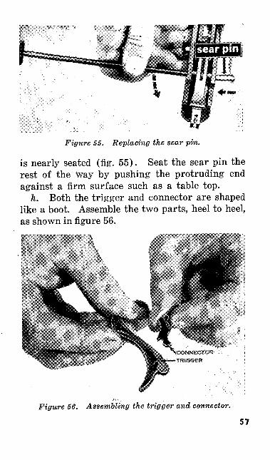
Figure 55. Replacing the sear pin.
is nearly seated (fig. 55). Seat the sear pin the rest of the way by pushing the protruding end against a firm surface such as a table top.
h. Both the trigger and connector are shaped like a boot. Assemble the two parts, heel to heel, as shown in figure 56.
Figure 56. Assembling the trigger and connector. ~
57
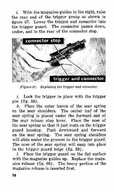
i. With the magazine guides to the right, raise the rear end of the trigger group as shown in figure 57. Lower the trigger and connector into the trigger guard. The connector passes down, under, and to the rear of the connector stop.
trigger and connector-.
Figure 57. Replacing the trigger and connector.
j. Lock the trigger in place with the trigger pin (fig. 58).
k. Place the outer leaves of the sear spring on the sear shoulders. The center leaf of the sear spring is placed under the forward end of the sear release stop lever. Place the nose of the sear spring so that it just rests on the trigger guard housing. Push downward and forward on the sear spring. The sear spring shoulders will slide under the grooves in the trigger guard. The nose of the sear spring will snap into place in the trigger guard ledge (fig. 59).
I. Place the trigger guard on the flat surface with the magazine guides up. Replace the maga zine release (fig. 60). The heavy portion of the magazine release is inserted first.58
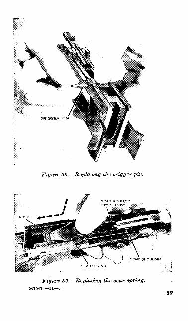
Figure 58. Replacing the trigger pin.
Figure 59. Replacing the sear spring.947041°—51—5
59
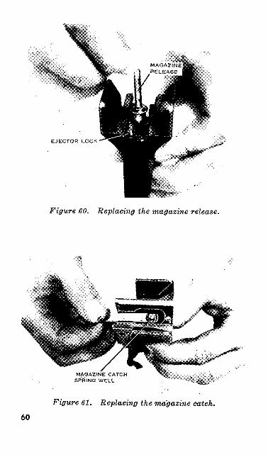
EJECTOR UOCK
Figure 60. Replacing the magazine release.
MAGAZINE CATCH SPRING WELL
Figure 61. Replacing the magazine catch.
60
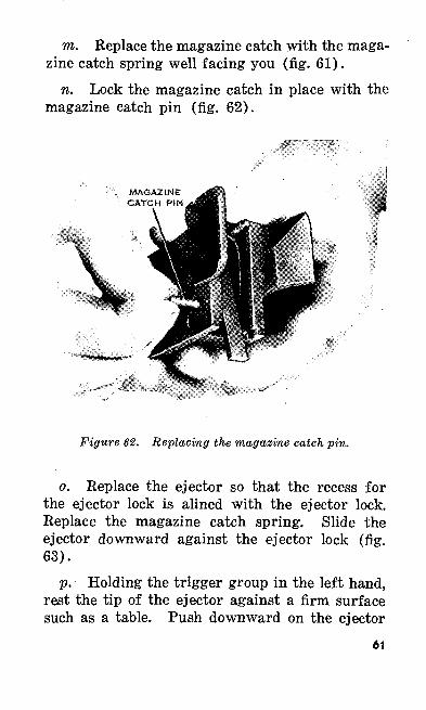
m. Replace the magazine catch with the maga zine catch spring well facing you (fig. 61).
n. Lock the magazine catch in place with the magazine catch pin (fig. 62).
MAGAZINE CATCH PIN
Figure 62. Replacing the magazine catch pin.
o. Replace the ejector so that the recess for the ejector lock is alined with the ejector lock. Replace the magazine catch spring. Slide the ejector downward against the ejector lock (fig. 63).
p. Holding the trigger group in the left hand, rest the tip of the ejector against a firm surface such as a table. Push downward on the ejector
61
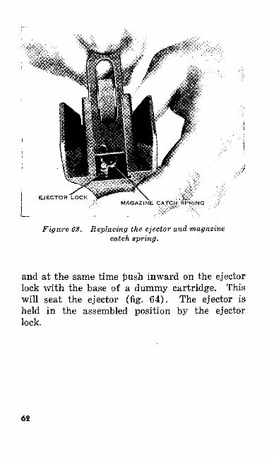
Figure 63. Replacing the ejector and magazine catch spring.
and at the same time push inward on the ejector lock with the base of a dummy cartridge. This will seat the ejector (fig. 64). The ejector is held in the assembled position by the ejector lock.
62
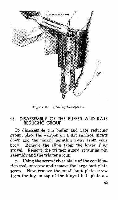
Figure 64- Seating the ejector.
15. DISASSEMBLY OF THE BUFFER AND RATE REDUCING GROUP
To disassemble the buffer and rate reducing group, place the weapon on a flat surface, sights down and the muzzle pointing away from your body. Remove the sling from the lower sling swivel. Remove the trigger guard retaining pin assembly and the trigger group.
a. Using the screwdriver blade of the combina tion tool, unscrew and remove the large butt plate screw. Now remove the small butt plate screw from the lug on top of the hinged butt plate as-
63
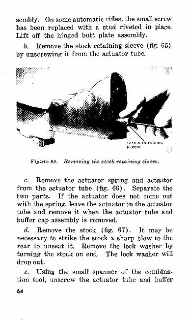
sembly. On some automatic rifles, the small screw has been replaced with a stud riveted in place. Lift off the hinged butt plate assembly.
b. Remove the stock retaining sleeve (fig. 65) by unscrewing it from the actuator tube.
Figure 65. Removing the stock retaining sleeve.
c. Remove the actuator spring and actuator from the actuator tube (fig. 66). Separate the two parts. If the actuator does not come out with the spring, leave the actuator in the actuator tube and remove it when the actuator tube and buffer cap assembly is removed.
d. Remove the stock (fig. 67). It may be necessary to strike the stock a sharp blow to the rear to unseat it. Remove the lock washer by turning the stock on end. The lock washer will drop out.
e. Using the small spanner of the combina tion tool, unscrew the actuator tube and buffer64
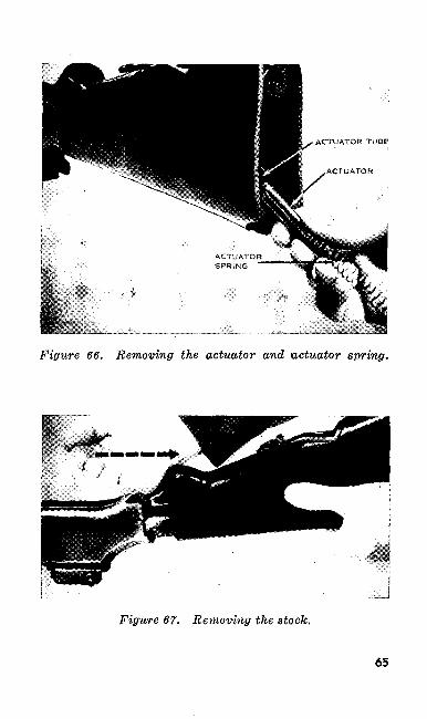
ACTUATOR TUBE
Figure 66. Removing the actuator and uctuator spring.
Figure 67. Removing the stock.
65
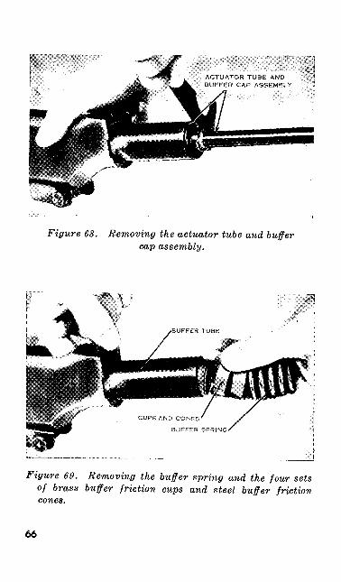
Figure 68. Removing the actuator tube and buffer cap assembly.
Figure 69. Removing the buffer spring and the four sets of brass buffer friction cups and steel buffer friction cones.
66
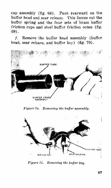
cap assembly (fig. 68). Push rearward on the buffer head and sear release. This forces out the buffer spring and the four sets of brass buffer friction cups and steel buffer friction cones (fig. 69).
/. Remove the buffer head assembly (buffer head, sear release, and buffer key) (fig. 70).
SUFFER HBAO, ASSEMBLY
Figure 70. Removing the buffer assembly.
BUFFER HEAC
BUfFER KEY SEAR RELEASE
Figure 71. Removing the buffer key.
67
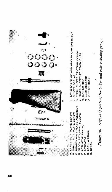
A,
LA
RG
E B
UT
T P
LA
TE
SC
RE
WB
. S
MA
LL B
UT
T P
LA
TE
SC
RE
WC
. H
ING
ED
BU
TT
PL
AT
E A
SS
EM
BL
YD
. S
TO
CK
R
ET
AIN
ING
SLE
EV
EE
. A
CT
UA
TO
R S
PR
ING
F.
AC
TU
AT
OR
G.
LO
CK
W
AS
HE
RH
. ST
OC
K
I. A
CT
UA
TO
R T
UB
E
AN
D S
UF
FE
R C
AP
AS
SE
MB
LY
J.
BU
FF
ER
SP
RIN
GK
. S
TE
EL
BU
FF
ER
F
RIC
TIO
N C
ON
ES
L.
BR
AS
S
BU
FF
ER
F
RIC
TIO
N
CU
PS
M.
BU
FF
ER
K
EY
N. SEAR RELEASE
O. BUFFER HEAD
Fig
ure
72.
Layo
ut o
f par
ts o
f the
buf
fer
and
rate
red
ucin
g gr
oup.
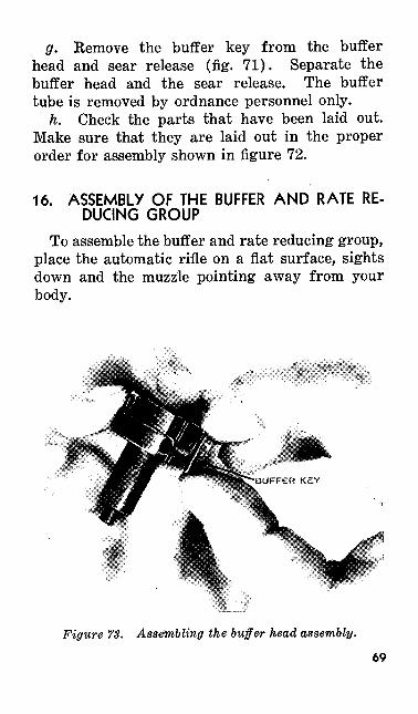
g. Remove the buffer key from the buffer head and sear release (fig. 71). Separate the buffer head and the sear release. The buffer tube is removed by ordnance personnel only.
h. Check the parts that have been laid out. Make sure that they are laid out in the proper order for assembly shown in figure 72.
16. ASSEMBLY OF THE BUFFER AND RATE RE DUCING GROUP
To assemble the buffer and rate reducing group, place the automatic rifle on a flat surface, sights down and the muzzle pointing away from your body.
Figure 73. Assembling the buffer head assembly.
69
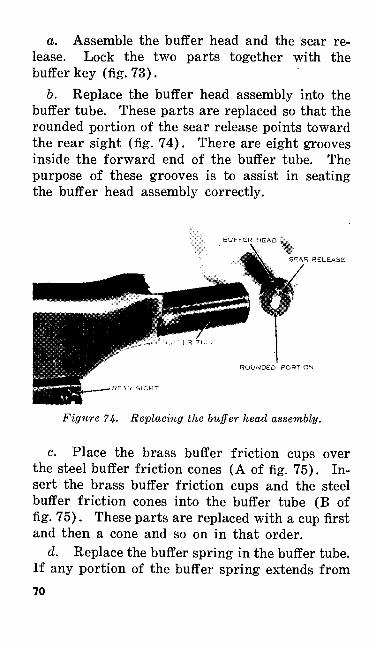
a. Assemble the buffer head and the sear re lease. Lock the two parts together with the buffer key (fig. 73).
b. Replace the buffer head assembly into the buffer tube. These parts are replaced so that the rounded portion of the sear release points toward the rear sight (fig. 74). There are eight grooves inside the forward end of the buffer tube. The purpose of these grooves is to assist in seating the buffer head assembly correctly.
BUFFER HEAD 1.
SFAR RELEASE
ROUNDED PORTION
Figure 74- Replacing the buffer head assembly.
c. Place the brass buffer friction cups over the steel buffer friction cones (A of fig. 75). In sert the brass buffer friction cups and the steel buffer friction cones into the buffer tube (B of fig. 75). These parts are replaced with a cup first and then a cone and so on in that order.
d. Replace the buffer spring in the buffer tube. If any portion of the buffer spring extends from70
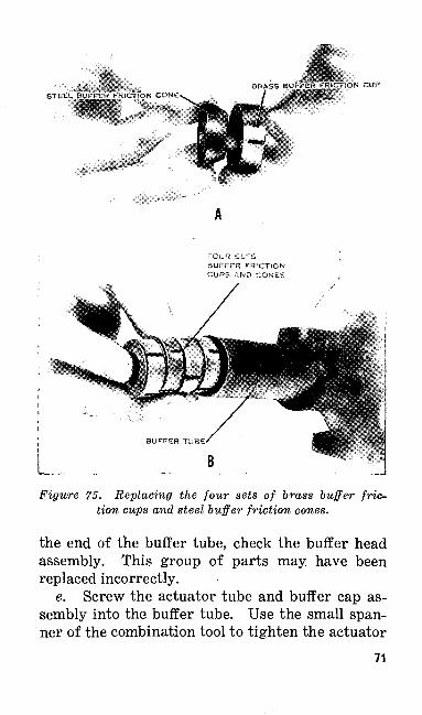
UFFER FfttCYiON CUP
FOUR SETS BUFFER FRICTION CUPS AND CONES
Figure 75. Replacing the four sets of brass buffer fric tion cups and steel buffer friction cones.
the end of the buffer tube, check the buffer head assembly. This group of parts may have been replaced incorrectly.
e. Screw the actuator tube and buffer cap as sembly into the buffer tube. Use the small span ner of the combination tool to tighten the actuator
71
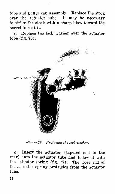
tube and buffer cap assembly. Replace the stock over the actuator tube. It may be necessary to strike the stock with a sharp blow toward the barrel to seat it.
/. Replace the lock washer over the actuator tube (fig. 76).
ACTUATOR TUBE,
Figure 76. Replacing the lock washer.
g. Insert the actuator (tapered end to the rear) into the actuator tube and follow it with the actuator spring (fig. 77). The loose end of the actuator spring protrudes from the actuator tube.72
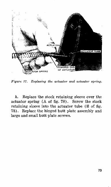
Figure 77. Replacing the actuator and actuator spring.
h. Replace the stock retaining sleeve over the actuator spring (A of fig. 78). Screw the stock retaining sleeve into the actuator tube (B of fig. 78). Replace the hinged butt plate assembly and large and small butt plate screws.
73
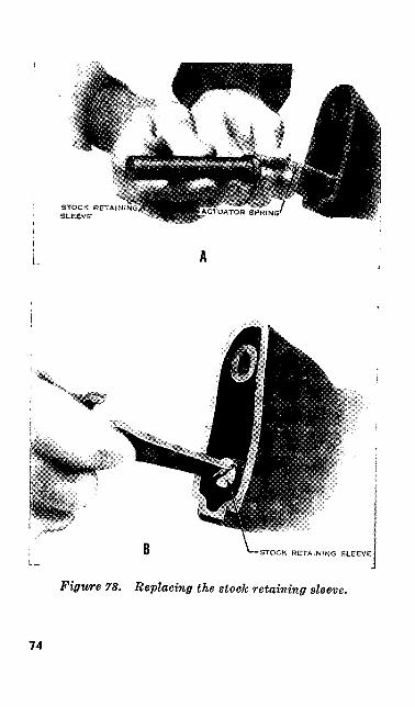
STOCK RETAINING SLESVE
STOCK RETAINING SLEEVE
Figure 78. Replacing the stock retaining sleeve.
74
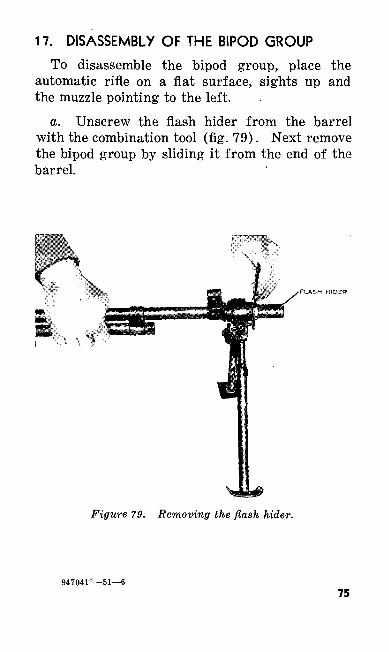
17. DISASSEMBLY OF THE BIPOD GROUP
To disassemble the bipod group, place the automatic rifle on a flat surface, sights up and the muzzle pointing to the left.
a. Unscrew the flash hider from the barrel with the combination tool (fig. 79). Next remove the bipod group by sliding it from the end of the barrel.
• FLASH HIDER
Figure 79. Removing the flash hider.
947041°—51—675
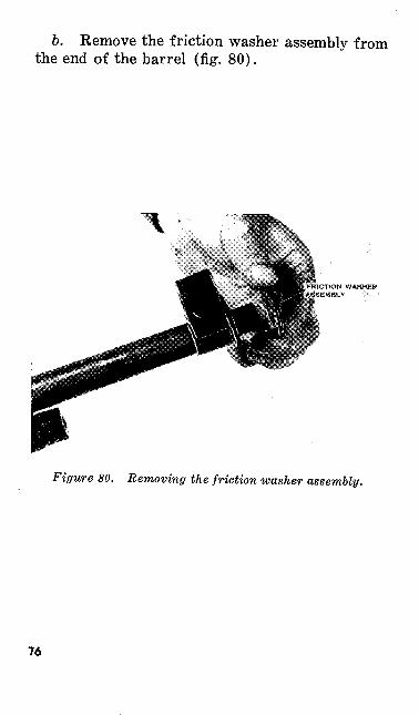
6. Remove the friction washer assembly from the end of the barrel (fig. 80).
ICTfQN WASHER
Figure 80. Removing the friction washer assembly.
76
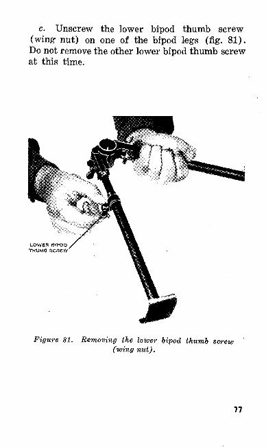
c. Unscrew the lower bipod thumb screw (wing nut) on one of the bipod legs (fig1 . 81). Do not remove the other lower bipod thumb screw at this time.
LOWER BIPOD THUMS SCREW
Figure 81. Removing the lower bipod thumb screw (wing nut).
77
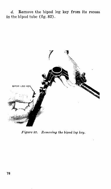
d. Remove the bipod leg key from its recess in the bipod tube (fig. 82).
Figure 82. Removing the bipod leg key.
78
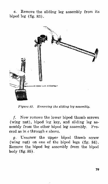
e. Remove the sliding leg assembly from its bipod leg (fig. 83).
Figure 83. Removing the sliding leg assembly.
f. Now remove the lower bipod thumb screws (wing nut), bipod leg key, and sliding leg as sembly from the other bipod leg assembly. Pro ceed as in c through e above.
g. Unscrew the upper bipod thumb screw (wing nut) on one of the bipod legs (fig. 84). Remove the bipod leg assembly from the bipod body (fig. 85).
79
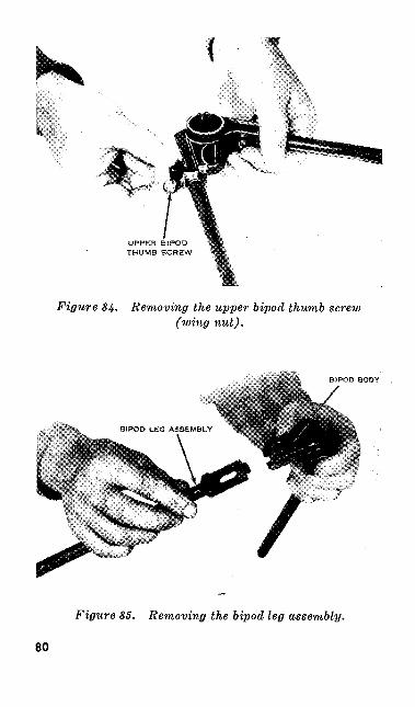
UPPER BIPOD THUMB SCREW
Figure 84. Removing the upper bipod thumb screw (wing nut).
Figure 85. Removing the bipod leg assembly.
80
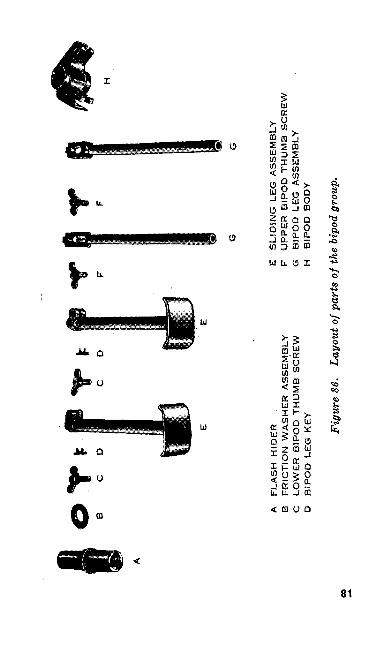
A
FLA
SH
H
IDE
R
.8
F
RIC
TIO
N W
AS
HE
R A
SS
EM
BL
YC
L
OW
ER
B
IPO
D T
HU
MB
S
CR
EW
D
BIP
OD
L
EG
K
EY
E
SL
IDIN
G L
EG
A
SS
EM
BL
YF
U
PP
ER
B
IPO
D T
HU
MB
S
CR
EW
G
BIP
OD
L
EG
A
SS
EM
BL
YH
B
IPO
D
BO
DY
Figu
re 8
6.
Layo
ut o
f par
ts o
f the
bip
od g
roup
.
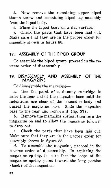
h. Now remove the remaining upper bipod thumb screw and remaining bipod leg assembly from the bipod body.
i. Place the bipod body on a flat surface.j. Check the parts that have been laid out.
Make sure that they are in the proper order for assembly shown in figure 86.
18. ASSEMBLY OF THE BIPOD GROUP
To assemble the bipod group, proceed in the re verse order of disassembly.
19. DISASSEMBLY AND ASSEMBLY OF THE MAGAZINE
To disassemble the magazine—a. Use the point of a dummy cartridge to
raise the rear end of the magazine base until the indentions are clear of the magazine body and unseat the magazine base. Slide the magazine base to the rear and remove it (fig. 87).
b. Remove the magazine spring, then turn the magazine on end to allow the magazine follower to drop out.
c. Check the parts that have been laid out. Make sure that they are in the proper order for assembly shown in figure 88.
d. To assemble the magazine, proceed in the reverse order of disassembly. In replacing the magazine spring, be sure that the loops of the magazine spring point toward the long portion (back) of the magazine.
82
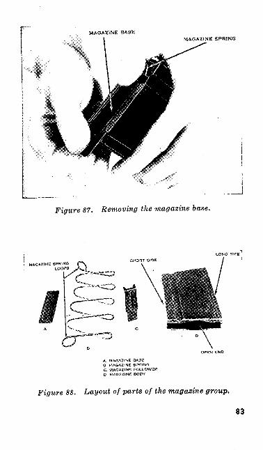
MAGAZINE BASEMAGAZINE SPRING
..-J
Figure 57. Removing the magazine base.
SHORT SIDE
A. MAGAZINE BASE 8_ MAGAZINE: SPRUNGC MA©AXfNG FOLLOWER
Figure 88. Layout of parts of the magazine group.
83
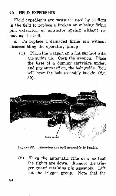
20. FIELD EXPEDIENTS
Field expedients are measures used by soldiers in the field to replace a broken or missing firing pin, extractor, or extractor spring without re moving the bolt.
a. To replace a damaged firing pin without disassembling the operating group—
(1) Place the weapon on a flat surface with the sights up. Cock the weapon. Place the base of a dummy cartridge under, and pry outward on, the bolt guide. You will hear the bolt assembly buckle (fig. 89).
BOLT GUIDE
Figure 89. Allowing the bolt assembly to buckle.
(2) Turn the automatic rifle over so that the sights are down. Remove the trig ger guard retaining pin assembly. Lift out the trigger group. Note that the
84
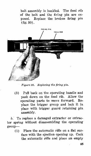
bolt assembly is buckled. The feed rib of the bolt and the firing pin are ex posed. Replace the broken firing pin (fig. 90).
FIRING PIN
Figure 90. Replacing the firing pin.
(3) Pull back on the operating handle and push down on the feed rib. Allow the operating parts to move forward. Re place the trigger group and lock it in place with trigger guard retaining pin assembly.
6. To replace a damaged extractor or extrac tor spring without disassembling the operating group—
(1) Place the automatic rifle on a flat sur face with the ejection opening up. Cock the automatic rifle and place an empty
85
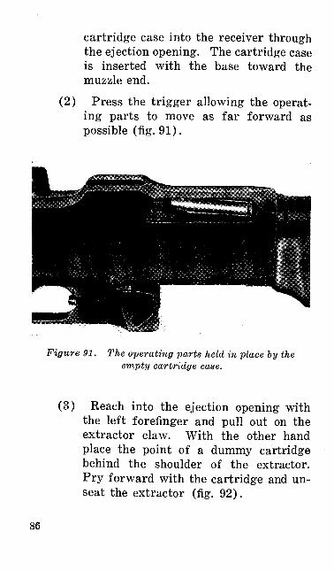
cartridge case into the receiver through the ejection opening. The cartridge case is inserted with the base toward the muzzle end.
(2) Press the trigger allowing the operat ing parts to move as far forward as possible (fig. 91).
Figure 91. The operating parts held in place by the empty cartridge case.
(3) Reach into the ejection opening with the left forefinger and pull out on the extractor claw. With the other hand place the point of a dummy cartridge behind the shoulder of the extractor. Pry forward with the cartridge and un seat the extractor (fig. 92).
86
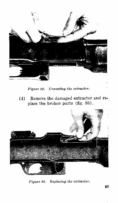
Figure 92. Unseating the extractor.
(4) Remove the damaged extractor and re place the broken parts (fig. 93).
Figure 93. Replacing the extractor.87
(5) Pull the operating handle all the way to the rear and remove the empty car tridge case. Allow the parts to move for ward.
SECTION III. FUNCTIONING
21. GENERAL
a. The automatic rifleman must understand functioning, or how and why his automatic rifle operates. Stoppages will occur with the auto matic rifle as with any other automatic weapon. When you understand how your weapon functions you will be able to locate and reduce stoppages quickly.
b. You are not expected to be a technical ex pert on the functioning of the automatic rifle. This section is designed to provide only a simple explanation of each function as it occurs.
22. WHAT FUNCTIONING IS
All automatic weapons must have some mechani cal means of unlocking, extracting, ejecting, cock ing, feeding, locking, and firing each round. These functions are performed by various cams, lugs, and springs located on your weapon.
23. THE FUNCTIONING CYCLE
Functioning of the automatic rifle may be di vided into two movements—the rearward move ment of the operating parts and then the for ward movement. These two movements together88
make up one functioning cycle. In the auto matic rifle, the energy for the rearward move ment of the operating parts comes from the gas developed by the exploding cartridge. This gas expands rapidly and develops enough pressure to move operating parts to the rear. As the parts move to the rear, the recoil spring is compressed, storing up energy for the forward movement. The rearward movement stops when the slide strikes the sear release and buffer head. ' The forward movement starts shortly thereafter.
24. FUNCTIONING OF THE OPERATING GROUP
a. In paragraphs 11 and 12, you became famil iar with the name of the parts contained in the operating group. Now you will see what these parts do as the operating group functions. The movement of the operating parts to the rear and their return comprises one firing or functioning cycle. Each phase may be divided into separate steps.
(1) Rearward movement—(a) Action of the gas.(&) Movement of the slide to the rear.(c) Unlocking.(d) Withdrawal of the firing pin.(e) Extraction.(/) Ejection.(g) Termination of the rearward move
ment.89
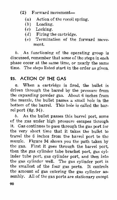
(2) Forward movement—(a) Action of the recoil spring. (&) Loading.(c) Locking.(d) Firing the cartridge.(e) Termination of the forward move
ment.
b. As functioning of the operating group is discussed, remember that some of the steps in each phase occur at the same time, or nearly the same time. The steps listed start in the order as given.
25. ACTION OF THE GASa. When a cartridge is fired, the bullet is
driven through the barrel by the pressure from the expanding powder gas. About 6 inches from the muzzle, the bullet passes a small hole in the bottom of the barrel. This hole is called the bar rel port (fig. 94).
6. As the bullet passes this barrel port, some of the gas under high pressure escapes through it. Gas continues to pass through the gas port for the very short time that it takes the bullet to travel the 6 inches from the barrel port to the muzzle. Figure 94 shows you the path taken by the gas. First it goes through the barrel port, then the gas cylinder tube bracket port, gas cyl inder tube port, gas cylinder port, and then into the gas cylinder well. The gas cylinder port is the smallest of the four gas ports. It controls the amount of gas entering the gas cylinder as sembly. All of the gas ports are stationary except90
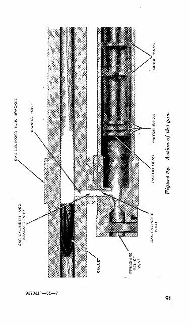
GAS CYLINDER TUBE
BRACKET PORT
GAS CYLINDER TUBE BRACKET
PRESSURE
RELIEF
VENT
OAS CYLINDER
PORT
7P
IST
ON
H
EA
D
PIS
TO
N
RIN
SS
Fig
ure
94.
Act
ion
of th
e ga
s.
OU
IDE
R
ING
S
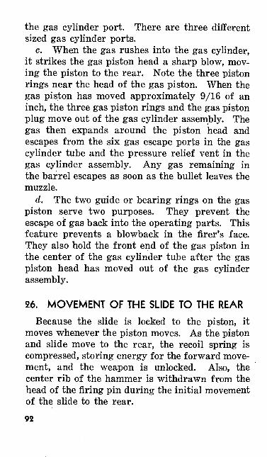
the gas cylinder port. There are three different sized gas cylinder ports.
c. When the gas rushes into the gas cylinder, it strikes the gas piston head a sharp blow, mov ing the piston to the rear. Note the three piston rings near the head of the gas piston. When the gas piston has moved approximately 9/16 of an inch, the three gas piston rings and the gas piston plug move out of the gas cylinder assembly. The gas then expands around the piston head and escapes from the six gas escape ports in the gas cylinder tube and the pressure relief vent in the gas cylinder assembly. Any gas remaining in the barrel escapes as soon as the bullet leaves the muzzle.
d. The two guide or bearing rings on the gas piston serve two purposes. They prevent the escape of gas back into the operating parts. This feature prevents a blowback in the firer's face. They also hold the front end of the gas piston in the center of the gas cylinder tube after the gas piston head has moved out of the gas cylinder assembly.
26. MOVEMENT OF THE SLIDE TO THE REAR
Because the slide is locked to the piston, it moves whenever the piston moves. As the piston and slide move to the rear, the recoil spring is compressed, storing energy for the forward move ment, and the weapon is unlocked. Also, the center rib of the hammer is withdrawn from the head of the firing pin during the initial movement of the slide to the rear.92
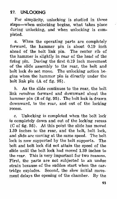
27. UNLOCKING
For simplicity, unlocking is studied in three steps—when unlocking begins, what takes place during unlocking, and when unlocking is com pleted.
a. When the operating parts are completely forward, the hammer pin is about 0.19 inch ahead of the bolt link pin. The center rib of the hammer is slightly in rear of the head of the firing pin. During the first 0.19 inch movement of the slide assembly to the rear, the bolt and bolt lock do not move. The unlocking action be gins when the hammer pin is directly under the bolt link pin (A of fig. 95).
6. As the slide continues to the rear, the bolt link revolves forward and downward about the hammer pin (B of fig. 95). The bolt lock is drawn downward, to the rear, and out of the locking recess.
c. Unlocking is completed when the bolt lock is completely down and out of the locking recess (C of fig. 95). At this point the slide has moved 1.39 inches to the rear, and the bolt, bolt lock, and slide are moving at the same speed. The bolt lock is now supported by the bolt supports. The bolt and bolt lock did not attain the speed of the slide until the bolt lock had moved 1.39 inches to the rear. This is very important for two reasons. First, the parts are not subjected to an undue strain because of the sudden start when the car tridge explodes. Second, the slow initial move ment delays the opening of the chamber. By the
93
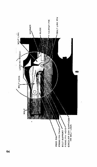
BO
LT
LO
CK
LO
CK
.NG
EC
ES
S
FE
ED
R
IB
FIR
ING
PIN
TA
NS
BO
LT
SU
PP
OR
T
FIR
ING
PIN
H
EA
D
CIR
CU
LA
R C
AM
S
UR
FA
CE
S
ON
B
OLT
LO
CK
HA
MM
ER
FIN
BO
LT
LIN
K P
IN
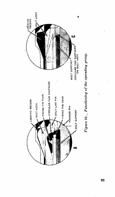
LO
CK
ING
R
EC
ES
S
BO
LT
LO
CK
FtR
INC
P
IN T
AN
G
'
CIR
CU
LA
R C
AM
SU
RF
AC
ES
BO
LT
LIN
K P
IN
FIR
ING
P
IN
HE
AD
HA
MM
ER
P
IN
BO
LT
SU
PP
OR
T
BO
LT
SU
PP
OR
T
CIR
CU
LA
R C
AM
S
UR
FA
CE
S
ON
B
OL
T
LO
CK
BO
LT
LO
CK
Fig
ure
95. .
Fun
ctio
ning
of t
he o
pera
ting
grou
p.
•o Ul
time the chamber opens, the gas pressure has been greatly reduced. This action prevents pow der gases from blowing back into the firer's face.
28. WITHDRAWAL OF THE FIRING PINAs the bolt lock moves downward from the lock
ing recess, the firing pin is withdrawn (fig. 95). A cam surface in the slot on the underside of the bolt lock operates on a cam surface on the tang of the firing pin. This action forces the striker of the firing pin back into the face of the bolt.
29. EXTRACTIONThe extractor is located on the upper right side
of the bolt next to the ejection opening. Keep in mind that the extractor grasps the rim of the cartridge. This action holds the base of the car tridge firmly against the face of the bolt. When the automatic rifle is fired, the empty cartridge case expands and binds against the chamber, so there -must be some means of loosening the cartridge case before removing it. During their initial movement, the bolt and bolt lock move slowly in comparison with the movement of the slide. As the bolt lock moves downward from the locking recess during unlocking, the circular cam surfaces on the undersides of the bolt lock act on the rear shoulders of the bolt supports (fig. 95). This contact produces a strong lever action, known as slow initial extraction, that loosens the empty cartridge case. When the bolt lock is down and out of the locking recess, the bolt, drawn by the bolt lock and bolt link, moves96
to the rear with the same speed as the slide as sembly. The empty case is carried with and held against the face of the bolt by the extractor.
30. EJECTION
The ejector is located in the trigger group. When the slide reaches a point approximately 14 inch from the end of its travel, the base of the cartridge case strikes the ejector. The cartridge case pivots about the extractor and passes through the ejection opening. As the bolt continues to the rear, the side of the cartridge case strikes the side of the receiver to the rear of the ejection opening and is ejected to the right front.
1. TERMINATION OF THE REARWARD MOVE MENT
The rearward movement of the operating parts stops when the rear of the slide strikes the sear release and then the buffer head.
32. ACTION OF THE RECOIL SPRING
As the parts move to the rear, the recoil spring is compressed. This action stores the necessary energy for the forward movement. The parts will move forward if the trigger is held or pressed to the rear. When the trigger is pressed, the sear nose is depressed and is disengaged from the sear notch on the slide. The slide assembly is then free to move forward under the force of the expanding recoil spring. As the slide moves forward, it carries the operating parts with it.
97
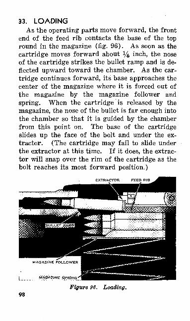
33. LOADINGAs the operating parts move forward, the front
end of the feed rib contacts the base of the top round in the magazine (fig. 96). As soon as the cartridge moves forward about 14 inch, the nose of the cartridge strikes the bullet ramp and is de flected upward toward the chamber. As the car tridge continues forward, its base approaches the center of the magazine where it is forced out of the magazine by the magazine follower and spring. When the cartridge is released by the magazine, the nose of the bullet is far enough into the chamber so that it is guided by the chamber from this point on. The base of the cartridge slides up the face of the bolt and under the ex tractor. (The cartridge may fail to slide under the extractor at this time. If it does, the extrac tor will snap over the rim of the cartridge as the bolt reaches its most forward position.)
EXTRACTOR
MAGAZINE SfMIKS*
Figure 96. Loading.98
34. LOCKING
Locking begins when the slide is about two inches from, its most forward position. At this point the circular cam surfaces on the underside of the bolt lock contact the rounded rear shoulders of the bolt supports (C of fig. 95). The bolt con tinues forward and the bolt link moves upward and to the rear about the hammer pin. As the bolt link moves upward, it forces the bolt lock upward and into the locking recess in the top of the receiver (B of fig. 95). In its forward move ment, the speed of the bolt assembly decreases gradually from the instant the bolt lock starts to rise until the hammer pin passes under the bolt link pin. This reduces the possibility of damag-. ing the firing pin. Locking is completed when the hammer pin is directly under the bolt link pin (A of fig. 95).
35. FIRING THE CARTRIDGE
The tang of the firing pin is buried in the slot on the underside of the bolt lock at all times except when the bolt lock is in the locking recess. This keeps the head of the firing pin locked away from the center rib of the hammer during the rear ward and forward motion of the bolt assembly, so that the weapon cannot fire. When locking is completed, the bolt lock is in the locking recess, the tang of the firing pin is no longer buried in the bolt lock, and the head of the firing pin can be struck by the center rib of the hammer. The slide and hammer continue forward another 1/10 inch after the bolt lock is in the locking recess.
99
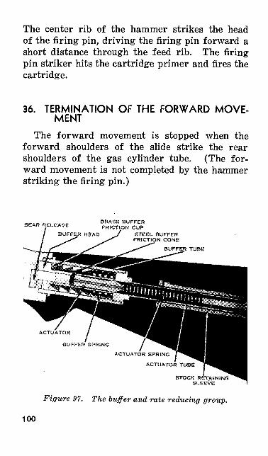
The center rib of the hammer strikes the head of the firing pin, driving the firing pin forward a short distance through the feed rib. The firing pin striker hits the cartridge primer and fires the cartridge.
36. TERMINATION OF THE FORWARD MOVE MENT
The forward movement is stopped when the forward shoulders of the slide strike the rear shoulders of the gas cylinder tube. (The for ward movement is not completed by the hammer striking the firing pin.)
BRASS BUFFER FRICTION CUP
STEEL BUFFER FRICTION CONE
BUFFER TUBE
ACTUATOR
BUFFER SPRING
ACTUATOR SPRING
ACTUATOR TUBE
Figure 97. The buffer and rate reducing group.
100
37. FUNCTIONING OF THE BUFFER AND RATE REDUCING GROUP
a. The buffer and rate reducing group is lo cated in the stock of the automatic rifle (fig. 97). This group serves two purposes. First, it ab sorbs most of the recoil of the operating parts in their rearward movement. Second, it enables the automatic rifle to be fired at a cyclic rate of 350 to 550 rounds per minute (par. 5). The buffer and rate reducing group consists of two mechanisms, the buffer mechanism and the rate reducing mechanism.
b. The rate reducing portion of this group operates in conjunction with the trigger group. For this reason its functioning is explained with the functioning of the trigger group (par. 39).
38. FUNCTIONING OF THE BUFFER MECHANISM
a. The following parts are involved in the functioning of the buffer portion of the buffer and rate reducing groups: the buffer head, four brass buffer friction cups, four steel buffer fric tion cones, the buffer tube, and the buffer spring.
6. While the automatic rifle is firing, the movement of the operating parts to the rear stops when the rear of the slide strikes the sear release and then the buffer head. When this occurs, the sear release and buffer head move to the rear a short distance.
c. The buffer head strikes the first buffer friction cup. This cup expands over its buffer friction cone and against the inner wall of the buffer tube. This movement is continued through
101
each set of buffer friction cups and buffer fric tion cones. As the cups and cones move to the rear, the buffer spring is compressed. Friction is developed when the brass cups expand over their cones. Friction is also produced when the cups expand against the inner wall of the buffer tube. This friction absorbs most of the recoil of the operating parts.
d. A small part of the recoil is absorbed by the buffer spring as it is compressed. The primary purpose of the buffer spring, however, is to re turn the four sets of buffer friction cups and buffer friction cones to their proper position. The buffer head is returned to its proper position as the buffer friction cups and buffer friction cones are forced forward.
39. FUNCTIONING OF THE TRIGGER GROUP
a. The trigger group controls the automatic rifle's rate of fire. The desired rate is obtained by adjusting the change lever on the trigger group.
b. The change lever has three settings — S (safe), A (fast cyclic rate of approximately 550 rounds per minute), and F (slow cyclic rate of approximately 350 rounds per minute).
c. The change lever is held on the desired set ting by the action of the change lever spring. Move the change lever on your trigger group to the various settings. You can feel the action of the change lever spring.
d. To understand the functions of the trigger group, a knowledge of the names of the parts in-102
volved and their purpose is necessary. First dis assemble the trigger group, following the instruc tions in paragraph 13. Now look at figures 98© through 98© that illustrate some of the more im portant parts and surfaces involved in function ing of the trigger group. Study the following par agraphs that explain how they work.
e. Assemble the change and stop lever spring assembly and the change lever to the trigger guard. Move the change lever to each of its three settings. Note the position of the cut away portion of the change lever on all three settings. Also note the position of the metal tongue and the solid portion in the change lever bar for each of the settings. The only function of the change lever spring is to hold the change lever at the desired setting (fig. 98©).
/. Assemble the trigger and trigger pin in the trigger guard. Set the change lever on the S setting and press the trigger. Note that the shoulders of the trigger contact the solid portion of the change lever bar. Place the change lever on the A setting and press the trigger. Note that the shoulders of the trigger rise into the cut away portion of the change lever bar. The metal tongue in the cut away portion of the change lever bar is between the shoulders of the trigger. Place the change lever on the F setting and press the trigger. Note that the shoulders of the trigger again rise into the cut away portion of the change lever bar. The metal tongue has now been with drawn from between the shoulders of the trigger.
103
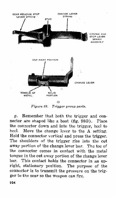
SEAR RELEASE STOP 'LEVER SPRtNG '
CHANGE LEVER SPRING
CHA«GE AND STOP tEVER
SPRING ASSEMBLY
CUT AWAY PORTION
TON6UE OF METAL
CHANGE LEVER
Figure 98. Trigger group parts.
g. Remember that both the trigger and con nector are shaped like a boot (fig. 98©). Place the connector down and into the trigger, heel to heel. Move the change lever to the A setting. Hold the connector vertical and press the trigger. The shoulders of the trigger rise into the cut away portion of the change lever bar. The toe of the connector comes in contact with the metal tongue in the cut away portion of the change lever bar. This contact holds the connector in an up right, stationary position. The purpose of the connector is to transmit the pressure on the trig ger to the sear so the weapon can fire.104
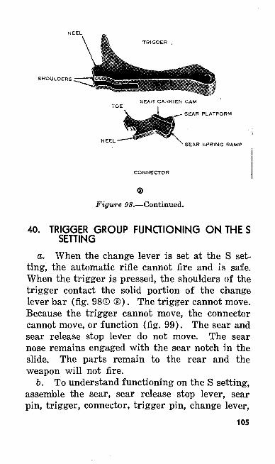
SHOULDERS
SEAR PLATFORM
SEAR SPRING RAMP
CONNECTOR
Figure 98.—Continued.
40. TRIGGER GROUP FUNCTIONING ON THE S SETTING
a. When the change lever is set at the S set ting, the automatic rifle cannot fire and is safe. When the trigger is pressed, the shoulders of the trigger contact the solid portion of the change lever bar (fig. 98® ©). The trigger cannot move. Because the trigger cannot move, the connector cannot move, or function (fig. 99). The sear and sear release stop lever do not move. The sear nose remains engaged with the sear notch in the slide. The parts remain to the rear and the weapon will not fire.
b. To understand functioning on the S setting, assemble the sear, sear release stop lever, sear pin, trigger, connector, trigger pin, change lever,
105
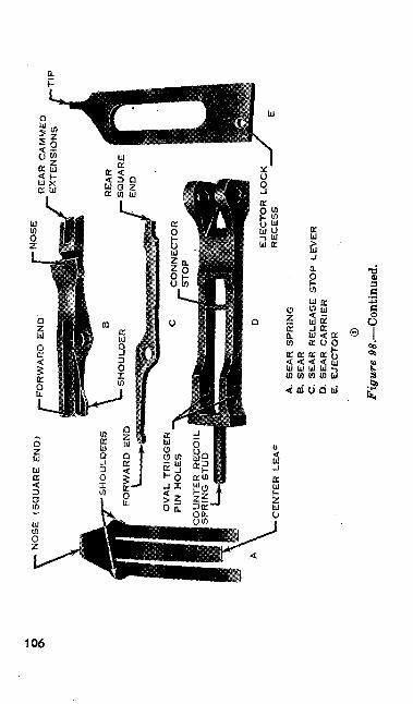
NO
SE
(SQ
UA
RE
END
)N
OSE
CO
UN
TER
REC
OIL
SP
RIN
G S
TUD
CEN
TER
LEA
F
REA
R C
AM
MED
EX
TEN
SIO
NS
I—T
IP
EJE
CT
OR
LO
CK
R
EC
ES
S
A.
SEA
R S
PRIN
GB
, SE
AR
C.
SE
AR
R
EL
EA
SE
ST
OP
LE
VE
R0.
SEA
R C
AR
RIE
RE.
EJE
CT
OR
Fig
ure
98. —
Con
tinue
d.
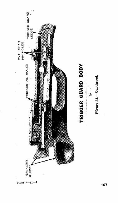
.- M
AG
AZI
NE
i. G
UID
E
OV
AL
SEA
R
PIN
HO
LE
S^T
RIG
GER
PIN
HO
LES
TRIG
GER
GU
AR
D
LED
GE
TR
IGG
ER
G
UA
RD
B
OD
Y
Fig
ure
98.—
Con
tinue
d.
and the change and stop lever spring assembly (fig. 98®, ®) to the trigger guard body (fig. 98©). Move the change lever to the S setting. As the trigger is pressed to the rear, this action can be followed easily on the trigger group.
41. TRIGGER GROUP FUNCTIONING ON THE A SETTING
a. As the change lever is rotated from the S to the A or fast cyclic rate setting, the solid por tion of the change lever bar rotates to the rear and out of the path of the trigger shoulders. The cutaway portion rotates into the path of the trig ger shoulders. The metal tongue in the cutaway portion of the change lever bar moves into the path of the toe of the connector. When the trig ger is pressed, the trigger shoulders move into the cutaway portion of the change lever bar and the connector is carried toward the sear by the trigger. The toe of the connector contacts the metal tongue in the cutaway portion. Because the connector contacts the metal tongue, the connec tor is held upright and in a stationary position (fig. 99).
6. As the connector moves up, it raises the for ward ends of the sear and sear release stop lever. The connector continues to hold up the forward ends of these parts as long as the trigger is held to the rear. The sear and sear release stop lever pivot on the sear pin. When the forward ends of these two parts are forced up, the rear ends pivot downward. Until this time the slide has
108
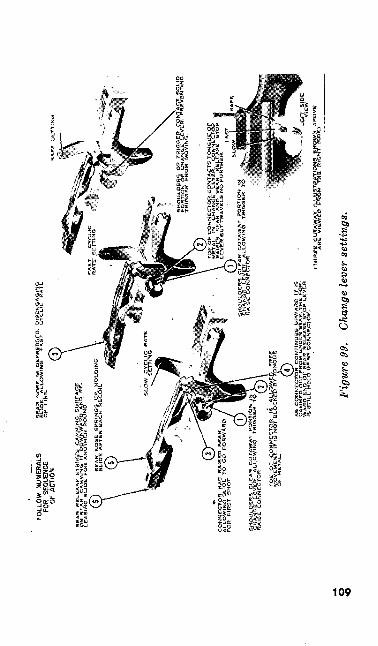
RX
LOW
N
UM
ERAL
SFO
R SE
QUE
NCE
OF A
CTIO
N
SE
AR
R
ET
UE
AIE
- S
TR
IKE
S
CA
MM
ING
S
UR
FA
CE
O
N
SC
AR
- C
AM
MIN
G
IT
DO
WN
WA
RD
A
ND
R
E
LE
AS
ING
S
L1Q
E
FO
R
AN
QT
HC
fi
RO
UN
D
'
T
SE
TT
ING
'OE
OF
CO
NN
EC
TO
R C
ON
TA
CT
S T
ON
GU
E I
*E
TA
L
SN
CH
AN
GE
L
EV
ER
. C
ON
NE
CT
* S
AfS
ES
S
fCA
H
AN
D
SE
AR
R
EL
FA
SE
S
T<
VE
R B
UT
TR
AV
EL
S N
O F
CAM
MED
OU
T FR
OM
UN
DC
f* S
EAR
. TH
E F
OR
W
ARD
EN
D O
f SE
AR R
ELE
AS
E S
TOP
LEV
D3
is S
TILL
HE
LD U
P B
Y C
ON
NEC
TOR
,
Figu
re 9
9.
Chan
ge le
ver
setti
ngs.
been engaged and held to the rear by the sear nose.
c. As the sear pivots about the sear pin, the sear nose is lowered and disengaged from the sear notch. This permits the slide assembly to move forward. The slide moves forward under action of the recoil spring which was compressed during the rearward movement of the operating parts.
d. When a round is fired, the slide moves to the rear and strikes the sear release and then the buffer head. If the trigger is held to the rear or is pressed again, the rear ends of the sear and sear release stop lever will be depressed. That is, the sear nose is down and out of the path of the sear notch on the slide. There is nothing to hold the slide to the rear. The operating parts move forward again and fire another round. The weapon continues to operate in this manner, fir ing at a rate of approximately 550 rounds per minute.
e. When the pressure on the trigger is re leased, the trigger is returned to its normal posi tion by the connector which is returned to its normal position by the center leaf of the sear spring. As the connector moves down, pressure against the forward ends of the sear and sear release stop lever is removed. The two outer leaves of the sear spring, which are resting on the shoulders of the sear, force the sear back into position. The sear release stop lever is reposi- tioned by its spring. The rear ends of the sear and sear release stop lever pivot upward. The110
sear nose is now up and in the path of the sear notch on the slide. The square end of the sear release stop lever is up and in the path of the sear release. The rear end of the sear release stop lever extends past the rear end of the sear.
/. At this time the rate reducing portion of the buffer and rate reducing group starts to func tion. When the operating parts return to the rear, the rear of the slide strikes the sear release and then the buffer head. The slide then moves forward a short distance and the sear nose en gages the sear notch on the slide. The sear re lease moves to the rear, strikes the actuator, and drives it to the rear through the actuator tube, compressing the actuator spring. When the actu ator spring expands, it drives the actuator for ward against the sear release. The sear release moves forward and strikes the blunt end of the sear release stop lever. As the blunt end of the sear release stop lever extends past the rear end of the sear, the sear release cannot contact the rear end of the sear. The sear nose remains en gaged with the sear notch and firing stops. When the trigger is held to the rear during firing, the rate reducing parts perform no function be cause the rear ends of the sear and sear release stop lever are forced down and the sear release passes over the rear ends of both parts.
g. Notice the oval-shaped sear pin holes in the trigger guard body and the sear carrier (fig. 98®, ©). When the slide is stopped by the sear nose engaging the sear notch on the slide, the sear nose is subjected to considerable shock.
111
To eliminate some of the wear on the sear nose caused by this shock as well as to eliminate the possibility of damaging the sear pin and trig ger pin, the oval sear pin and trigger pin holes and the counterrecoil spring are provided. When the slide assembly strikes the sear nose, the sear carrier moves forward a short distance. The sear pin moves in the oval shaped sear pin holes in the trigger guard body. This movement is made against the action of the counterrecoil spring. The shock and wear on the sear nose is reduced by this slight movement. The sear carrier is forced back to its original position as the counter- recoil spring expands.
42. TRIGGER GROUP FUNCTIONING ON THE F SETTING
a. Note what happens when the change lever is rotated from the A setting to the F or slow cyclic rate setting. The cutaway portion of the change lever bar moves further to the rear; how ever, it is still exposed to the shoulder of the trig ger. The metal tongue in the cutaway portion moves out of the path of the connector. When the trigger is pressed, the shoulders of the trigger move up and into the cutaway portion of the change lever bar. As the trigger moves up, the connector is carried up. The connector at first raises the forward ends of both the sear and the sear release stop lever. These two parts pivot about the sear pin; their rear ends move down ward. As the rear end of the sear moves down ward, the sear nose is disengaged from the sear112
notch on the slide. The operating parts then move forward under action of the compressed re coil spring as explained in paragraph 32.
b. On the F setting, the toe of the connector does not contact the metal tongue in the change lever bar. Therefore, there is nothing to hold the connector in an upright and stationary position. Note the cam surface (sear carrier ramp) on the connector (fig. 98©). Note also the cam sur face just in the rear of the connector stop on the underside of the sear carrier (fig. 98®). When the connector moves up, these two surfaces con tact each other and produce a camming action. This action forces the connector forward. The top of the connector is forced out from under the forward end of the sear and the connector falls forward against the connector stop (fig. 99). The connector continues to hold the forward end of the sear release stop lever in the up position. The sear is repositioned by the two outer leaves of the sear spring.
c. As the operating parts move to the rear under the action of the gas, the slide passes over the sear and strikes the sear release and then the buffer head. The slide then rebounds forward a short distance. The sear nose engages the sear notch on the slide, holding the operating parts to the rear. Meanwhile, the sear release of the buffer and rate reducing group moves to the rear a short distance and strikes the actuator. The actuator moves to the rear through the actuator tube and compresses the actuator spring. As the actuator spring expands, it drives the actuator forward.
113
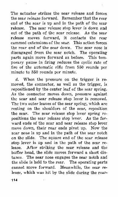
The actuator strikes the sear release and forces the sear release forward. Remember that the rear end of the sear is up and in the path of the sear release. The sear release stop lever is down and out of the path of the sear release. As the sear release moves forward, it contacts the rear cammed extensions of the sear. This action forces the rear end of the sear down. The sear nose is disengaged from the sear notch. The operating parts again move forward as before. This tem porary pause in firing reduces the cyclic rate of fire of the automatic rifle from 550 rounds per minute to 350 rounds per minute.
d. When the pressure on the trigger is re moved, the connector, as well as the trigger, is repositioned by the center leaf of the sear spring. As the connector moves down, pressure against the sear and sear release stop lever is removed. The two outer leaves of the sear spring, which are resting on the shoulders of the sear, reposition the sear. The sear release stop lever spring re positions the sear release stop lever. As the for ward ends of the sear and sear release stop lever move down, their rear ends pivot up. Now the sear nose is up and in the path of the sear notch on the slide. The square end of the sear release stop lever is up and in the path of the sear re lease. After striking the sear release and the buffer head, the slide moves forward a short dis tance. The sear nose engages the sear notch and the slide is held to the rear. The operating parts cannot move forward. Meanwhile, the sear re lease, which was hit by the slide during the rear-114
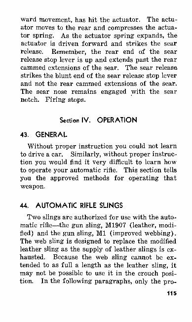
ward movement, has hit the actuator. The actu ator moves to the rear and compresses the actua tor spring. As the actuator spring expands, the actuator is driven forward and strikes the sear release. Remember, the rear end of the sear release stop lever is up and extends past the rear cammed extensions of the sear. The sear release strikes the blunt end of the sear release stop lever and not the rear cammed extensions of the sear. The sear nose remains engaged with the sear notch. Firing stops.
Section IV. OPERATION
43. GENERAL
Without proper instruction you could not learn to drive a car. Similarly, without proper instruc tion you would find it very difficult to learn how to operate your automatic rifle. This section tells you the approved methods for operating that weapon.
44. AUTOMATIC RIFLE SLINGS
Two slings are authorized for use with the auto matic rifle—the gun sling, M1907 (leather, modi fied) and the gun sling, Ml (improved webbing). The web sling is designed to replace the modified leather sling as the supply of leather slings is ex hausted. Because the web sling cannot be ex tended to as full a length as the leather sling, it may not be possible to use it in the crouch posi tion. In the following paragraphs, only the pro-
115
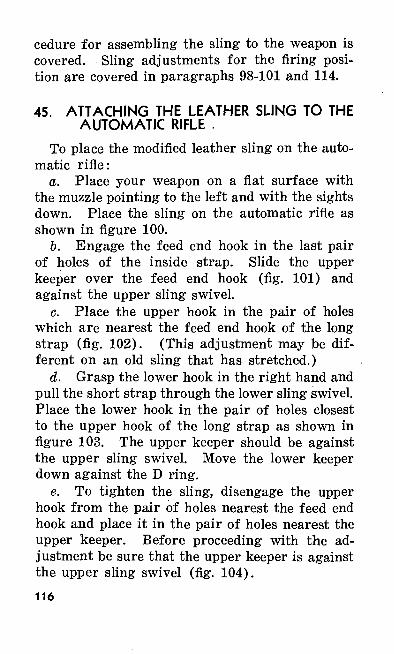
cedure for assembling the sling to the weapon is covered. Sling adjustments for the firing posi tion are covered in paragraphs 98-101 and 114.
45. ATTACHING THE LEATHER SLING TO THE AUTOMATIC RIFLE .
To place the modified leather sling on the auto matic rifle:
a. Place your weapon on a flat surface with the muzzle pointing to the left and with the sights down. Place the sling on the automatic rifle as shown in figure 100.
b. Engage the feed end hook in the last pair of holes of the inside strap. Slide the upper keeper over the feed end hook (fig. 101) and against the upper sling swivel.
c. Place the upper hook in the pair of holes which are nearest the feed end hook of the long strap (fig. 102). (This adjustment may be dif ferent on an old sling that has stretched.)
d. Grasp the lower hook in the right hand and pull the short strap through the lower sling swivel. Place the lower hook in the pair of holes closest to the upper hook of the long strap as shown in figure 103. The upper keeper should be against the upper sling swivel. Move the lower keeper down against the D ring.
e. To tighten the sling, disengage the upper hook from the pair of holes nearest the feed end hook and place it in the pair of holes nearest the upper keeper. Before proceeding with the ad justment be sure that the upper keeper is against the upper sling swivel (fig. 104).116
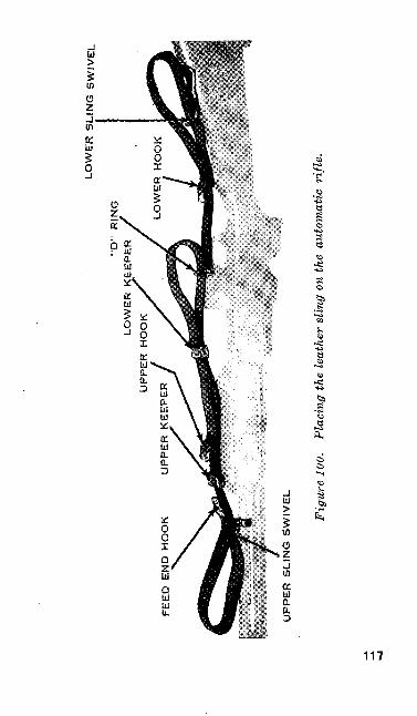
LO
WE
R S
LIN
G S
WIV
EL
FE
ED
EN
D H
OO
K
"D"
RIN
G
LOW
ER K
EE
PER
U
PPE
R H
OO
KL
OW
ER
HO
OK
UPP
ER
SL
ING
SW
IVE
L
Fig
ure
100.
Pl
acin
g th
e le
athe
r sl
ing
on th
e au
tom
atic
rifl
e.
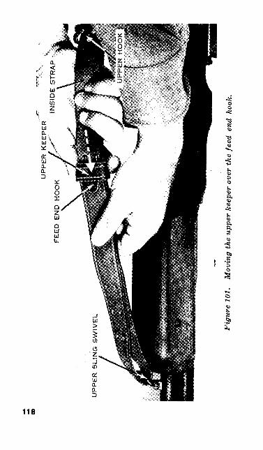
UPPER KEEPER
FEED END HOOK
UPP
ER
SL
ING
SW
IVE
L
Fig
ure
101.
M
ovin
g th
e up
per
keep
er o
ver
the
feed
end
hoo
k.
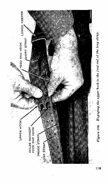
UPP
ER
HO
OK
HO
LE
S N
EA
RE
ST
FEE
D E
ND
HO
OK
LO
WE
R K
EE
PER
INSI
DE
ST
RA
P
LON
G S
TRA
PS
Fig
ure
102.
E
ngag
ing
the
uppe
r ho
ok to
the
feed
end
of
the
long
str
ap.
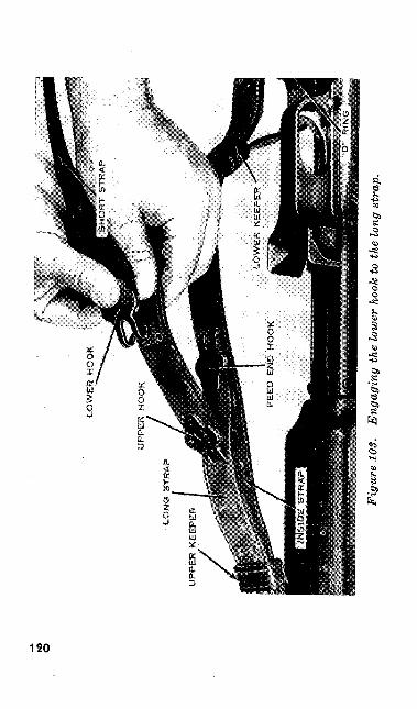
K5 O
Fig
ure
103.
E
ngag
ing
the
low
er h
ook
to t
he lo
ng s
trap
.
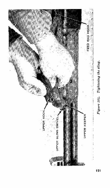
Fig
ure
104-
Ti
ghte
ning
the
slin
g.
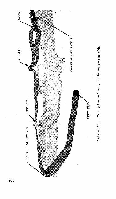
to
to
OO
K
UPP
ER
SLI
NG
SW
IVE
L
.KE
EPE
R
FEE
D E
ND
Fig
ure
105,
Pl
acin
g th
e w
eb s
ling
on th
e au
tom
atic
rifl
e.
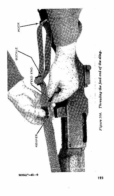
Figu
re 1
06.
Thre
adin
g th
e fe
ed e
nd o
f the
slin
g.
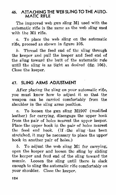
46. ATTACHING THE WEB SLING TO THE AUTO MATIC RIFLE
The improved web gun sling Ml used with the automatic rifle is the same as the web sling used with the Ml rifle.
a. To place the web sling on the automatic rifle, proceed as shown in figure 105.
6. Thread the feed end of the sling through the keeper and pull the keeper and feed end of the sling toward the butt of the automatic nrie until the sling is as tight as desired (fig. 106). Close the keeper.
47. SLING ARMS ADJUSTMENT
After placing the sling on your automatic rifle, you must know how to adjust it so that the weapon can be carried comfortably from the shoulder in the sling arms position.
a. To loosen the gun sling M1907 (modified leather) for carrying, disengage the upper hook from the pair of holes nearest the upper keeper. Place the upper hook in the pair of holes nearest the feed end hook. (If =the sling -has been stretched, it may be necessary to place the upper" hook in another pair of holes.)
b. To adjust the web sling Ml for carrying, open the keeper and loosen the sling by sliding the keeper and feed end of the sling toward the muzzle. Loosen the sling until there is slack enough to sling the automatic rifle comfortably on your shoulder. Close the keeper.
124
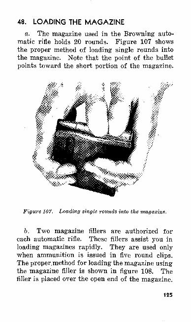
48. LOADING THE MAGAZINE
a. The magazine used in the Browning auto matic rifle holds 20 rounds. Figure 107 shows the proper method of loading single rounds into the magazine. Note that the point of the bullet points toward the short portion of the magazine.
Figure 107. Loading single rounds into the magazine.
b. Two magazine fillers are authorized for each automatic rifle. These fillers assist you in loading magazines rapidly. They are used only when ammunition is issued in five round clips. The proper, method for loading the magazine using the magazine filler is shown in figure 108. The filler is placed over the open end of the magazine.
125
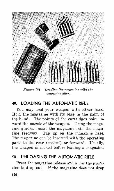
Figure 108. Loading the magazine with the magazine filler.
49. LOADING THE AUTOMATIC RIFLEYou may load your weapon with either hand.
Hold the magazine with its base in the palm of the hand. The points of the cartridges point to ward the muzzle of the weapon. Using the maga zine guides, insert the magazine into the maga zine feedway. Tap up on the magazine base. The magazine can be inserted with the operating- parts to the rear (cocked) or forward. Usually, the weapon is cocked before loading a magazine.
50. UNLOADING THE AUTOMATIC RIFLEPress the magazine release and allow the maga
zine to drop out. If the magazine does not drop126
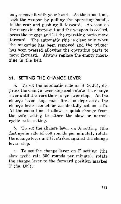
out, remove it with your hand. At the same time, cock the weapon by pulling the operating handle to the rear and pushing it forward. As soon as the magazine drops out and the weapon is cocked, press the trigger and let the operating parts move forward. The automatic rifle is clear only when the magazine has been removed and the trigger has been pressed allowing the operating parts to move forward. Always replace the empty maga zine in the belt.
51. SETTING THE CHANGE LEVER
a. To set the automatic rifle on S (safe), de press the change lever stop and rotate the change lever until it covers the change lever stop. As the change lever stop must first be depressed, the change lever cannot be accidentally set on safe. At the same time it allows a quick change from the safe setting to either the slow or normal cyclic rate setting.
b. To set the change lever on A setting (the fast cyclic rate of 550 rounds per minute), rotate the change lever until it strikes against the change lever stop.
c. To set the change lever on F setting (the slow cyclic rate 350 rounds per minute), rotate the change lever to the forward position marked F (fig.109).
127
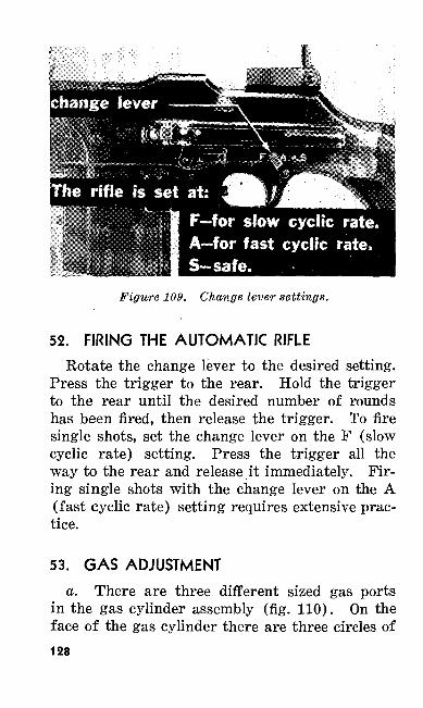
Figure 109. Change lever settings.
52. FIRING THE AUTOMATIC RIFLE
Rotate the change lever to the desired setting. Press the trigger to the rear. Hold the trigger to the rear until the desired number of rounds has been fired, then release the trigger. To fire single shots, set the change lever on the F (slow cyclic rate) setting. Press the trigger all the way to the rear and release it immediately. Fir ing single shots with the change lever on the A (fast cyclic rate) setting requires extensive prac tice.
53. GAS ADJUSTMENT
a. There are three different sized gas ports in the gas cylinder assembly (fig. 110). On the face of the gas cylinder there are three circles of128
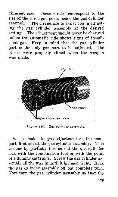
different size. These circles correspond to the size of the three gas ports inside the gas cylinder assembly. The circles are to assist you in adjust ing the gas cylinder assembly at the desired setting. The adjustment should never be changed unless the automatic rifle shows signs of insuffi cient gas. Keep in mind that the gas cylinder port is the only gas port to be adjusted. The others were properly alined when the weapon was made.
GAS PORT
^CYLINDER LOCK
Figure 110. Gas cylinder assembly.
b. To make the gas adjustment on the small port, first unlock the gas cylinder assembly. This is done by partially forcing out the gas cylinder lock with the combination tool or with the point of a dummy cartridge. Screw the gas cylinder as sembly all the way in until it is finger tight. Back the gas cylinder assembly off one complete turn. Now turn the gas cylinder assembly so that the
129
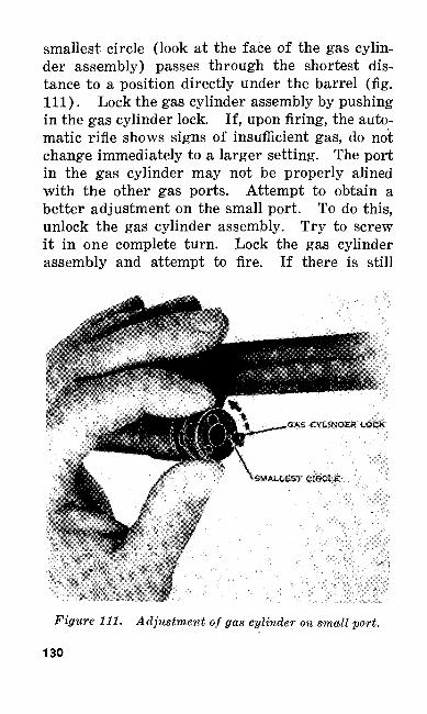
smallest circle (look at the face of the gas cylin der assembly) passes through the shortest dis tance to a position directly under the barrel (fig. Ill). Lock the gas cylinder assembly by pushing in the gas cylinder lock. If, upon firing, the auto matic rifle shows signs of insufficient gas, do not change immediately to a larger setting. The port in the gas cylinder may not be properly alined with the other gas ports. Attempt to obtain a better adjustment on the small port. To do this, unlock the gas cylinder assembly. Try to screw it in one complete turn. Lock the gas cylinder assembly and attempt to fire. If there is still
Figure 111. Adjustment of gas cylinder on small port.
130
insufficient gas, unlock the gas cylinder assembly and unscrew it two complete turns. Lock the gas cylinder assembly and attempt to fire. If the weapon is still receiving insufficient gas, adjust the gas cylinder on the next larger port.
c. Adjust the gas cylinder assembly on the medium and large ports in the same manner as on the small port. If, upon adjusting the gas cylinder assembly on the medium or the large port, the weapon still does not receive sufficient gas, attempt to obtain a better alinement of the gas ports. The method to be followed .is the same as was followed for the small port.
54. SAFETY PRECAUTIONS
a. General. You must constantly be on the alert when working with any weapon.
b. Precautions. Several basic ground rules are observed in handling the automatic rifle. These rules are not intended to replace other ex isting safety regulations. Additional safety pre cautions are listed in paragraphs 231-235.
(1) Never place any obstruction in the muz zle or bore.
(2) Always assume the automatic rifle to be loaded when a magazine is in the re ceiver or the operating parts are to the rear.
(B) While on the range, carry the weapon v/ith the muzzle'up and pointing down range at all times.
131
(4) Never carry the weapon when loaded ex cept in combat or during combat exer cises. In combat exercises your officers will tell you when to load.
.(5) While on the range, clear your auto matic rifle before leaving the firing lines.
(6) Carry the rifle with the bolt forward at all times except when in the presence of the enemy.
(7) Before all periods of mechanical and preparatory marksmanship training, check each weapon and magazine for the presence of live rounds.
Section V. STOPPAGES AND IMMEDIATE ACTION
55. GENERAL
a. A stoppage is any unintentional or acci dental failure to fire. In other words, a stoppage occurs when the weapon stops firing through no fault of the automatic rifleman. A stoppage may be a>failure to feed, eject, fire, or function freely. It is caused by faulty operation of the automatic rifle, magazine, or ammunition.
6. A malfunction is the faulty action of some part of a weapon resulting in a stoppage.
c. Immediate action is the unhesitating appli cation of a probable remedy without considering the cause of the stoppage. It is that action which the automatic rifleman performs immediately on his weapon when it fails to fire.132
56. COMMON CAUSES OF STOPPAGES
a. Most of the mechanical failures of the auto matic rifle are caused by worn, weak, broken, or dirty operating parts. You must train yourself to watch for these defects and correct them before they cause a stoppage. The primary cause of stoppages is a defective magazine. For this rea son it is particularly important that you handle the magazines carefully. Take proper care of the magazines and the weapon itself, and you can rely on your automatic rifle to function properly when you need it. Four types of common stoppages, their usual causes, and the action to take to cor rect them are described below. You should ex amine your automatic rifle before, during, and after firing with these causes in mind. In this manner, many stoppages can be prevented.
133
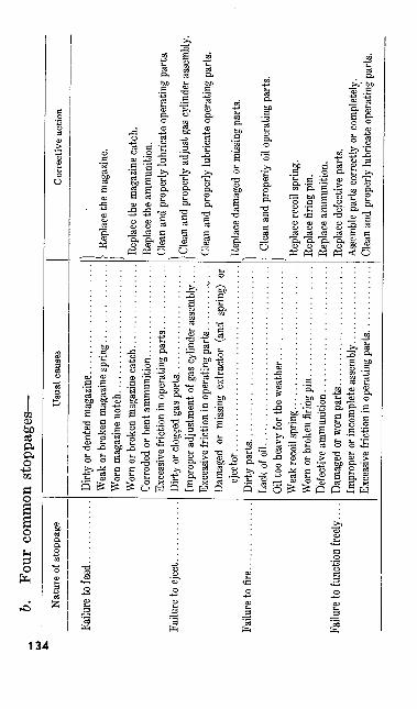
_L b.
Four
com
mon
sto
ppag
es—
u>
________________________________
Nat
ure
of s
topp
age
Failu
re to
feed
......
....
Failu
re to
eje
ct.
Failu
re to
fire
...
Failu
re to
func
tion
freely
.
Usu
al c
ause
s
Dirty
or de
nted
maga
zine.
....
....
....
....
....
..W
eak
or b
roke
n m
agaz
ine s
pri
ng................
Wor
n m
agaz
ine n
otc
h..........................
Wor
n or
bro
ken
mag
azin
e cat
ch.................
Corro
ded
or b
ent a
mm
unit
ion.
......
......
......
Exce
ssiv
e fric
tion
in o
pera
ting
par
ts.............
Dirt
y or
clog
ged
gas p
ort
s......................
Impr
oper
adj
ustm
ent o
f gas
cylin
der a
ssem
bly.
...
Exce
ssiv
e fric
tion
in o
pera
ting
parts
. ....... .^
,...
Dam
aged
or
miss
ing
extra
ctor
(an
d sp
ring)
or
ejec
tor.
....
....
....
....
....
....
....
....
....
Dirt
y part
s...................................
Lack
of o
il..
....
....
....
....
....
..............
Oil t
oo h
eavy
for t
he w
eath
er...................
Wea
k rec
oil s
pri
ng.............................
Wor
n or
bro
ken
firin
g pin
......................
Defe
ctive
am
mu
nit
ion
....
....
....
....
....
....
.Da
mage
d or
worn
part
s....
......
......
......
..Im
prop
er o
r inc
ompl
ete a
ssem
bly.
......
......
...Ex
cess
ive f
rictio
n in
ope
ratin
g pa
rts. .
...........
Cor
rect
ive
actio
n
? Re
plac
e the
mag
azin
e.
Repl
ace t
he m
agaz
ine
catc
h.Re
place
the a
mmun
ition
.Cl
ean
and
prop
erly
lubr
icat
e op
erati
ng p
arts.
/Cle
an an
d pr
oper
ly a
djus
t gas
cylin
der a
ssem
bly.
Clea
n an
d pr
oper
ly lu
bric
ate
oper
ating
par
ts.
Kepl
ace
dam
aged
or m
issin
g pa
rts.
I }• Cl
ean
and
prop
erly
oil
oper
ating
par
ts.
Repl
ace r
ecoi
l spr
ing.
Repla
ce fi
ring p
in.Re
plac
e am
mun
ition
.Re
plac
e def
ectiv
e par
ts.As
semb
le pa
rts c
orre
ctly
or c
ompl
etely
.Cl
ean
and
prop
erly
lubr
icate
oper
ating
par
ts.
57. APPLYING IMMEDIATE ACTION
Although many stoppages can be prevented be fore they occur if the weapon, magazines, and ammunition are cared for properly, some stop pages may still occur. Immediate action is taught so that you will be able to take the necessary steps to reduce those stoppages. Immediate action is taught and performed in two phases.
58. FIRST PHASE OF IMMEDIATE ACTION
The first phase of immediate action is taught as a drill. It must be applied quickly and without thought as to the cause of the stoppage. Most stoppages can be eliminated by applying the first phase of immediate action. The five key words that are used to help you learn and remember the first phase of immediate action are—Pull, Push, Tap, Aim, and Fire. An explanation of the five key words follows:
a. PULL the operating handle all the way to the rear. This action should eject any empty rounds remaining in the chamber, providing the extractor, extractor spring, or the ejector is not broken.
b. PUSH the operating handle all the way for ward. The weapon is now cocked.
c. TAP up firmly on the bottom of the maga zine. If the magazine is not fully seated, this should seat it, providing the magazine notch or magazine catch is not worn.
d. AIM and attempt to FIRE.
135
59. SECOND PHASE OF IMMEDIATE ACTION
If the first phase of immediate action does not reduce the stoppage, then a more detailed exami nation of the automatic rifle must be made. The five key words used to help you remember the second phase of immediate action are—Take, Look, Pull, Locate, and Reduce. An explanation of these five words follows:
a. TAKE the automatic rifle from the shoulder.b. LOOK at the ejection opening.c. PULL the operating handle to the rear
slowly.d. LOCATE the stoppage by observing, as you
pull the operating handle to the rear, what is in the ejection opening, what is in the chamber, or what is ejected.
e. REDUCE the stoppage and attempt to fire the weapon.
60. SECOND PHASE STOPPAGES
While applying the second phase of immediate action, you will see certain stoppages. You must be able to locate their cause and eliminate them. Six of the more common stoppages are—
a. Partial Feeding (fig. 112).(1) Description. The weapon stops firing
with a live cartridge fed part way into the chamber. The feed rib is riding over the cartridge. The base of the cartridge is still in the magazine. This type of stoppage is known as partial feeding and is caused by a faulty magazine. The
136
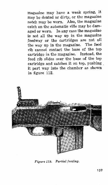
magazine may have a weak spring, it may be dented or dirty, or the magazine notch may be worn. Also, the magazine catch on the automatic rifle may be dam aged or worn. In any case the magazine is not all the way up in the magazine feedway or the cartridges are not all the way up in the magazine. The feed rib cannot contact the base of the top cartridge in the magazine. Instead, the feed rib slides over the base of the top cartridge and catches it on top, pushing it part way into the chamber as shown in figure 112.
Figure 112. Partial feeding.
137
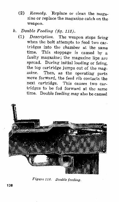
(2) Remedy. Replace or clean the maga zine or replace the magazine catch on the weapon.
6. Double Feeding (fig. 113).(1) Description. The weapon stops firing
when the bolt attempts to feed two car tridges into the chamber at the same time. This stoppage is caused by a faulty magazine; the magazine lips are spread. During initial loading or firing, the top cartridge jumps out of the mag azine. Then, as the operating parts move forward, the feed rib contacts the next cartridge. This causes two car tridges to be fed forward at the same time. Double feeding may also be caused
Figure 113. Double feeding.138
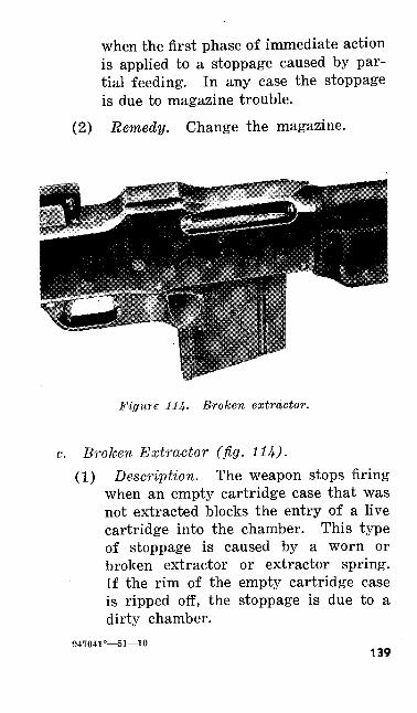
when the first phase of immediate action is applied to a stoppage caused by par tial feeding. In any case the stoppage is due to magazine trouble.
(2) Remedy. Change the magazine.
Figure 114. Broken extractor.
c. Broken Extractor (fig. 114).(1) Description. The weapon stops firing
when an empty cartridge case that was not extracted blocks the entry of a live cartridge into the chamber. This type of stoppage is caused by a worn or broken extractor or extractor spring. If the rim of the empty cartridge case is ripped off, the stoppage is due to a dirty chamber.
947041°—51—10139
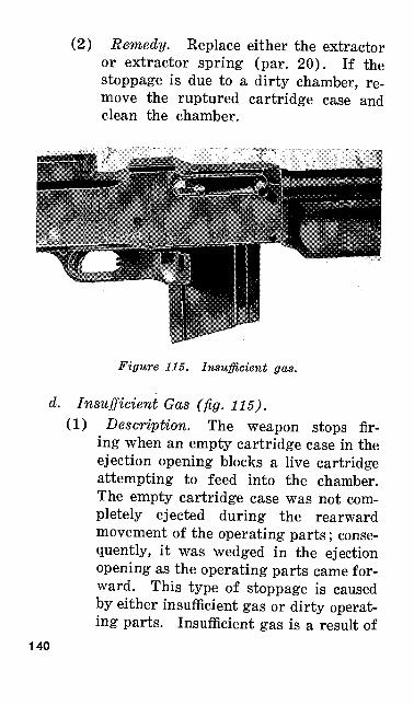
(2) Remedy. Replace either the extractor or extractor spring (par. 20). If the stoppage is due to a dirty chamber, re move the ruptured cartridge case and clean the chamber.
Figure 115. Insufficient gas.
d. Insufficient Gas (fig. 115).(1) Description. The weapon stops fir
ing when an empty cartridge case in the ejection opening blocks a live cartridge attempting to feed into the chamber. The empty cartridge case was not com pletely ejected during the rearward movement of the operating parts; conse quently, it was wedged in the ejection opening as the operating parts came for ward. This type of stoppage is caused by either insufficient gas or dirty operat ing parts. Insufficient gas is a result of
140
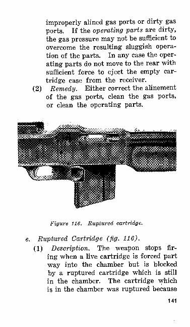
(2)
improperly alined gas ports or dirty gas ports. If the operating parts are dirty, the gas pressure may not be sufficient to overcome the resulting sluggish opera tion of the parts. In any case the oper ating parts do not move to the rear with sufficient force to eject the empty car tridge case from the receiver.
Remedy. Either correct the alinement of the gas ports, clean the gas ports, or clean the operating parts.
Figure 116. Ruptured cartridge.
e. Ruptured Cartridge (fig. 116).(1) Description. The weapon stops fir
ing when a live cartridge is forced part way into the chamber but is blocked by a ruptured cartridge which is still in the chamber. The cartridge which is in the chamber was ruptured because
141
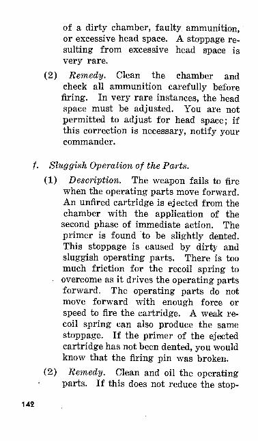
of a dirty chamber, faulty ammunition, or excessive head space. A stoppage re sulting from excessive head space is very rare.
(2) Remedy. Clean the chamber and check all ammunition carefully before firing. In very rare instances, the head space must be adjusted. You are not permitted to adjust for head space; if this correction is necessary, notify your commander.
f. Sluggish Operation of the Parts.(1) Description. The weapon fails to fire
when the operating parts move forward. An unfired cartridge is ejected from the chamber with the application of the second phase of immediate action. The primer is found to be slightly dented. This stoppage is caused by dirty and sluggish operating parts. There is too much friction for the recoil spring to overcome as it drives the operating parts forward. The operating parts do not move forward with enough force or speed to fire the cartridge. A weak re coil spring can also produce the same stoppage. If the primer of the ejected cartridge has not been dented, you would know that the firing pin was broken.
(2) Remedy. Clean and oil the operating parts. If this does not reduce the stop-
142
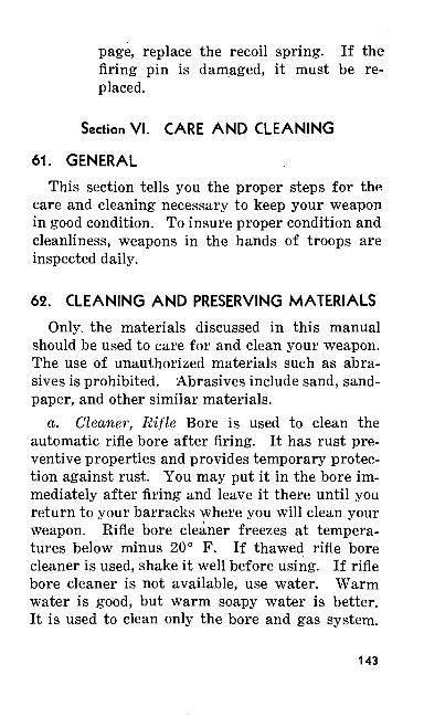
page, replace the recoil spring. If the firing pin is damaged, it must be re placed.
Section VI. CARE AND CLEANING
61. GENERAL
This section tells you the proper steps for the care and cleaning necessary to keep your weapon in good condition. To insure proper condition and cleanliness, weapons in the hands of troops are inspected daily.
62. CLEANING AND PRESERVING MATERIALS
Only, the materials discussed in this manual should be used to care for and clean your weapon. The use of unauthorized materials such as abra sives is prohibited. Abrasives include sand, sand paper, and other similar materials.
a. Cleaner, Rifle Bore is used to clean the automatic rifle bore after firing. It has rust pre ventive properties and provides temporary protec tion against rust. You may put it in the bore im mediately after firing and leave it there until you return to your barracks where you will clean your weapon. Rifle bore cleaner freezes at tempera tures below minus 20° F. If thawed rifle bore cleaner is used, shake it well before using. If rifle bore cleaner is not available, use water. Warm water is good, but warm soapy water is better. It is used to clean only the bore and gas system.
143
b. Oil, Preservative, Lubricating, (special) is a thin oil used for lubricating at normal and low temperatures and for temporary protection against rusting. Use this oil for preserving the bore between times that the automatic rifle is fired. Apply it after the automatic rifle has been cleaned and make frequent inspections to be sure that there is always a good protective oil film. Special preservatives lubricating oil fulfills all lubrication requirements for which the light grade oil has been prescribed. When present stocks of light preservative lubricating oil are exhausted, requisitions will be filled automatically with spe cial preservative lubricating oil.
c. Oil, Preservative, Lubricating, (medium) is superior to special preservative lubricating oil for small arms exposed to salt water atmosphere. The oil is heavier and possesses better preserva tive characteristics for such conditions. It pre vents rusting and forms a fairly heavy film of oil that resists the direct action of salt spray. It should be used in preference to special preserva tive lubricating oil for coating all parts of the weapons before landing operations.
d. Oil, Engine, SAE 10 may be used when the oils mentioned above cannot be obtained. In cold weather any oil as heavy as this causes sluggish operation and may prevent the automatic rifle from working. This alternate oil does not possess the rust preventive properties of preservative lubricating oils. When engine oil is used, the weapons must be examined, cleaned, and re-oiled frequently.144
e. Compound, Rust Preventive, medium, pro tects metal parts for long periods of time while automatic rifles are in storage. It should be warmed before application. When you have no way to heat it, brush it onto the parts when the temperature is above 80° F. At temperatures be low 80° F, light rust preventive compound be comes thick and sluggish and it is not economical to use it without preheating.
/. Solvent, Dry Cleaning, is an inflammable fluid. Do not smoke where it is being used. It is used for removing grease, oil, or rust preventive compound. Metal surfaces are bathed in the sol vent with rag swabs. After bathing, thoroughly wipe the solvent off all metal surfaces with clean rags. After cleaning with solvent, metal parts rust very' quickly from finger marks. Wipe off all finger marks. Cleaning solvent also harms and discolors rubber.
g. Oil, Linseed, Raw, is applied to the wooden parts of the automatic rifle to preserve the wood and to keep out moisture.
h. Oil, Neat's-Foot, is used for cleaning and softening the leather sling. Use it sparingly, rub it in well, and wipe it off carefully to prevent soil ing your clothes.
63. GENERAL INSTRUCTIONS FOR CARE AND CLEANING
a. Automatic rifles are disassembled only to the extent necessary for proper cleaning. When necessary, magazines are disassembled for clean ing and light lubrication. Magazines that are
145
handled carefully and kept clean will function properly.
b. Proper oiling is second in importance only to correct and frequent cleaning. The working parts must be oiled, but the oil should be used sparingly. A good way to apply the oil is to wipe the parts with a well oiled rag.
c. The buffer and rate reducing group and the trigger group are normally not disassembled each time the automatic rifle is cleaned. These two groups must be disassembled and cleaned after long periods of firing. Frequent cleaning of all parts is required if the weapon is fired in sandy terrain or near salt water.
64. CARE AND CLEANING WHEN THE AUTO MATIC RIFLE IS NOT USED
When no firing is being done, the automatic rifle and the magazines need only the care neces sary to preserve their condition and appearance.
a. To clean the automatic rifle bore, attach a dry patch to the cleaning rod and pass it through the bore. Insert the cleaning rod through the muzzle end of the weapon. Repeat this procedure with dry patches. If the bore is unusually dry, use an oily patch to loosen the dry film. Do this until several patches come out clean. Then push an oily patch through the bore. (See paragraph 62 for proper lubricants.) This light coat of oil protects the bore. Brush all screw heads and crevices with a small cleaning brush or wood splinter. Wipe all metal surfaces with a dry cloth to remove moisture, perspiration, and dirt. Wipe146
the outer surfaces of the automatic rifle, includ ing the forearm, with a lightly oiled cloth. This protective film must be maintained on all metal parts at all times. At least once a month, rub a little linseed oil into the forearm with the palm of the hand. If the forearm ever becomes wet, dry it and rub in linseed oil as soon as possible. Rub the oil in until the forearm is dry. Use neat's foot oil moderately for cleaning and softening the leather sling.
b. It is important to give magazines the best of care and to keep them in perfect condition. Keep them free from dirt and rust and handle them carefully to avoid dents or abrasions. To clean the magazine, disassemble it, wipe it clean and dry, and place a thin coat of oil on the parts.
65. CARE AND CLEANING AFTER FIRING
a. Thoroughly clean the bore of the automatic rifle by evening of the day on which it is fired. Repeat this cleaning for three successive days.
b. Clean the bore by swabbing it with a patch saturated with rifle bore cleaner. Repeat with several additional patches saturated with rifle bore cleaner. If rifle bore cleaner is not available, use warm, soapy water. While swabbing the bore with water, rest the automatic rifle on the toe of the butt with the muzzle elevated slightly. The water will drip out of the receiver and will not get into the buffer and rate reducing group and the locking recess. While the bore is still wet, run the metal brush through it several times. Remove the brush and swab the bore again with a patch
147
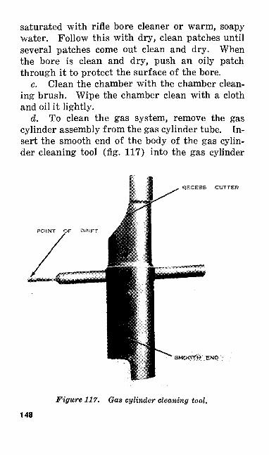
saturated with rifle bore cleaner or warm, soapy water. Follow this with dry, clean patches until several patches come out clean and dry. When the bore is clean and dry, push an oily patch through it to protect the surface of the bore.
c. Clean the chamber with the chamber clean ing brush. Wipe the chamber clean with a cloth and oil it lightly.
d. To clean the gas system, remove the gas cylinder assembly from the gas cylinder tube. In sert the smooth end of the body of the gas cylin der cleaning tool (fig. 117) into the gas cylinder
RECESS CUTTER
SMOOTW END
Figure 117. Gas cylinder cleaning tool.
148
assembly. Turn it to the right as you gradually scrape into the gas cylinder head. As it reaches the head, apply additional pressure to the tool. Give it a few turns to cut the carbon from the bot tom, inside surface of the gas cylinder. With draw and reverse the tool. Using the recess cut ter, remove the carbon from the recesses at the forward end of the interior of the gas cylinder assembly. With the point of the drift, clean the gas ports in the barrel, gas cylinder tube, and gas cylinder assembly. Scrape the carbon from the face of the gas piston with the front cutting edge. Remove the carbon deposit between the piston rings with the point of the drift. Wipe thoroughly with a rag saturated with rifle bore cleaner, if available. Otherwise, wash with warm, soapy water. If soap is not available, use plain water and dry thoroughly. Inspect for cleanli ness. When the gas piston is clean and dry, oil it lightly. Clean the gas cylinder tube with rifle bore cleaner or warm soapy water. If soap is not available, use plain warm or cold water. The gas cylinder tube may be cleaned easily by tying a cloth lightly in the center part of a length of string. Pull the cloth back and forth inside the gas cylinder tube. Dry thoroughly and inspect. When clean, oil lightly.
e. Wipe the remaining parts of the operating group clean and dry. Apply a thin film of oil.
/. Wipe the trigger group dry and oil lightly. It is disassembled periodically, or when necessary, for cleaning.
149
g. Wipe the outer metal parts of the automatic rifle dry. Apply a thin film of oil.
h. Clean the stock and forearm of the auto matic rifle. Wipe the sling with a clean, dry cloth.
i. Inspect the interior of the magazine as sembly by depressing the follower with the thumb. If the interior is dirty, disassemble and clean and then lightly oil the magazine assembly. Other wise, merely wipe the magazine assembly clean and dry and then oil it.
66. POINTS TO BE OBSERVED BEFORE, DURING, AND AFTER FIRING
The points listed below are preventive steps to be observed before, during, and after firing. These steps will eliminate many conditions that may cause a stoppage.
150

Item
Bo
re..
....
....
.
Cha
mbe
r....
...
Ope
ratin
g pa
rts..
Gas
sys
tem
.....
Trig
ger g
roup
...
Mag
azin
es.
Bef
ore
firin
g
Rem
ove
oil.
Clea
n th
orou
ghly
w
ith
cham
ber
clea
ning
bru
sh a
nd p
atch
es.
Wor
k sli
de b
ack
and
forth
to
insu
re
free
mov
emen
t. Oi
l lig
htly
if
nece
ssar
y.Ve
rify
prop
er s
ettin
g of
gas
por
t.
Test
at s
afe,
slow,
and
nor
mal
cyc
lic
rate
set
tings
.Cl
ean,
see t
hat s
prin
gs fu
nctio
n pr
op
erly
and
that
not
ches
are n
ot w
orn.
Dur
ing
(incl
udin
g te
mpo
rary
ce
ssat
ions
) fir
ing
Kee
p fre
e fro
m d
irt,
mud
, w
ater
and
sn
ow; c
lean
dur
ing
paus
es in
firin
g.Cl
ean
frequ
ently
. Us
e ch
ambe
r clea
ning
br
ush
durin
g pa
uses
whi
le au
tom
atic
rif
le is
hot.
Kee
p fre
e fro
m o
il.Oi
l per
iodi
cally
. K
eep
out d
irt a
nd d
ust..
Plac
e 3
or 4
dro
ps o
f oil
in
end
of g
as
cylin
der p
erio
dica
lly d
urin
g pa
uses
.
Han
dle
care
fully
, kee
p ou
t di
rt an
d gr
it;
avoi
d dr
oppi
ng in
dirt
or s
and.
Aft
er f
irin
g (p
ar.
65)
Clea
n an
d oil
.
Clea
n th
orou
ghly
; oil
light
ly.
Clea
n an
d oil
.
Clea
n an
d oil
.
Clea
n an
d oi
l.
Disa
ssem
ble,
clean
and
oil.
67. CARE AND CLEANING IN COLD CLIMATES
a. In temperatures below freezing, keep the moving parts of the automatic rifle absolutely free from moisture. In low temperatures excess oil on the working parts will thicken, causing sluggish operation or complete failure to func tion. Apply oil very sparingly. To do this, wet a cloth with special preservative lubricating oil, then wring it out and wipe all metal parts with the cloth.
b. Before using the automatic rifle in tempera tures below +32 °F, disassemble it and completely clean the working parts with dry cleaning solvent or its equivalent. Lubricate the working surfaces of parts which show signs of wear by rubbing them with a cloth slightly dampened with special preservative lubricating oil. The cloth is pre pared as described in a above. At temperatures above 32° F., lightly oil all metal surfaces after cleaning the weapon. Use medium preservative lubricating oil.
c. When the automatic rifle is brought indoors, first allow it to warm to room temperature. Then disassemble it, wipe it completely dry of the mois ture which will have condensed on the cold metal surfaces, and thoroughly oil it with special pre servative lubricating oil. Do this every time a weapon is carried into a warm room after expo sure to low temperature. If possible, avoid this condensation by providing a cold place in which to keep automatic rifles when not in use. A sep arate cold room with racks may be used. In the field, racks under proper cover may be set up.152
d. If the automatic rifle has been fired, clean and oil it thoroughly. The bore may be swabbed out with an oily patch. When the weapon reaches room temperature, thoroughly clean and oil it as described in paragraph 65.
e. Before firing, clean the automatic rifle and remove the oil as described in b above. The bore and chamber should be entirely free of oil before firing. In cold climates, the medium 'gas port is usually the most satisfactory initial setting of the gas cylinder.
68. CARE AND CLEANING IN HOT CLIMATES
a. Tropical Climates.(1) Use medium preservative lubricating
oil for lubrication. If the automatic rifle is to be exposed to salt water at mosphere, use medium preservative lub ricating oil.
(2) In tropical climates where tempera tures and humidity are high, or where salt air is present and also during rainy seasons in the less tropical climates, thoroughly inspect the automatic rifle daily. Keep it lightly oiled when not in use. Dismount the groups at regular intervals and, if necessary, disassemble them enough to dry and to oil the parts.
(3) Keep unexposed parts and surfaces clean and oiled.
(4) Inspect wooden parts to see that swell ing due to moisture does not bind work ing parts. If this condition exists, shave
153
off only enough wood to relieve binding. A light coat of raw linseed oil applied at intervals and rubbed in well with the heel of the hand will help to keep moisture out. Allow the oil to soak in for a few hours and then wipe and polish the wood with a clean, dry rag.Note. Care should be taken that linseed oil
does not get into the mechanism or on metal parts. Linseed oil becomes gummy when dry.
b. Hot, Dry Climates.(1) In hot, dry climates where sand and
dust are likely to get into the mechanism and bore, wipe the automatic rifle clean daily or more often if necessary. Dis mount and disassemble the groups as far as necessary to give them a thorough cleaning.
(2) When the automatic rifle is used under sandy conditions, wipe it completely dry of all lubricant. This will prevent sand from sticking to the lubricant. Sand and oil form an abrasive compound which is harmful to the mechanism. On leaving sandy terrain, wipe the auto matic rifle clean at once and relubricate it with light preservative lubricating oil.
(3) In hot, dry climates, the wood parts are likely to dry out and shrink. A light application of linseed oil will help to keep the wood in good condition. Apply it as directed in a (4) above.
154
(4) Perspiration from the hands contains salt which will cause rust. All metal parts must be wiped dry frequently.
(5) During sand or dust storms, keep the breech and muzzle covered when practi cable.
69. CARE WHEN SUBJECT TO CHEMICAL ATTACK
a. It is important to prevent chemical agents from coming into contact with the automatic rifle, ammunition, spare parts, and accessories. If a chemical attack is anticipated, or chemical con taminations are encountered, oil all the spare parts, accessories, and the outer metal surfaces of the automatic rifle, but do not oil the ammuni tion. If the automatic rifle is not to be used, cover it, the spare parts, accessories, and ammunition with protective tarpaulins. The equipment may be dispersed under natural cover. Keep ammuni tion in its original containers as long as possible.
b. After a chemical attack, check all materiel to determine if it has been contaminated. Test for toxic gas vapors with a detector crayon and test for liquid toxic chemicals with detector paper. If not contaminated, clean the materiel with rifle bore cleaner. Prepare the automatic rifle and its equipment for use as required.
70. DECONTAMINATIONa. To decontaminate automatic rifles, their
spare parts, and accessories, you must wear a complete set of protective clothing (permeable or
947041°—51—11155
impermeable), impermeable gloves, and a service gas mask.
b. Materiel contaminated with chemicals other than the blister agents or G-series agents can be decontaminated by airing. For faster decontami nation of these agents and to protect against cor rosion, clean the automatic rifle and -its equipment with rifle bore cleaner, denatured alcohol or soap and water.
c. To decontaminate materiel contaminated by blister agents—
(1) Remove dirt, dust, grease, and oil.(2) Allow surfaces to air.(3) Decontaminate all metal surfaces ex
cept the bore with noncorrosive decon taminating agent (DANG). Hot soapy water or repeated applications with gas oline soaked swabs are also effective for this decontamination.
(4) For emergency decontamination, use protective ointment M5, which is car ried in the gas mask carrier.
(5) Test the equipment with detector paper or the detector kit to see if decontamina tion is complete.
(6) After decontamination and subsequent tests have been completed, clean, dry, oil, and prepare the automatic rifle and its equipment for use as required.
(7) Bury all rags or wiping materials used during decontamination. If you cannot bury them, burn them. Be careful to protect yourself against vapors created by burning the cleaning materials.
156
d. Detailed information on decontamination is contained in FM 21-40 and TM 3-220.
e. In general, use the same methods outlined above to decontaminate automatic rifles and their equipment contaminated by biological or radio logical attack. If contamination is too great, it may be necessary to discard the contaminated items.
71. STORAGE
a. Preparation for Storage. Prepare auto matic rifles for storage with care. Thoroughly clean and then completely dry the bore, all parts of the mechanism, including the buffer and rate reducing group, and the exterior of the weapon. In damp climates, make sure that the rags used are dry. After a metal part has been dried, be careful not to touch it with bare hands. Take special care in cleaning the gas system to include the gas ports. Then coat all metal parts with either medium preservative lubricating oil or me dium rust preventive compound. The type used depends on the length of storage. Before placing the automatic rifle in the packing chest, paint the wooden supports for the butt and muzzle with rust preventive compound. Never store an auto matic rifle in a cloth or similar cover and never plug the bore. Such articles collect moisture that causes the automatic rifle to rust.
b. Cleaning When Received From Long Term Storage. Automatic rifles received from storage are coated with either preservative lubricating oil or with rust preventive compound. Weapons re-
157
ceived from ordnance storage usually have a coat of rust preventive compound. Use dry cleaning solvent or volatile mineral spirits paint thinner to remove all traces of the compound or oil. After using the cleaning solvent, make sure it is com pletely removed from all parts. Do this by wip ing with a dry cloth. Take particular care to clean thoroughly the gas system, gas ports, firing pin, and all recesses in which springs or plungers operate. Failure to clean the gas system, the fir ing pin, and the recesses of the bolt in which the firing pin operates may result in a stoppage at normal temperatures, and, at low temperatures, is almost certain to cause a serious malfunction. Rust preventive compound and other foreign mat ter cause lubricating oil to congeal on the mechan ism. This results in sluggish movement of the operating parts.
Section VII. SPARE PARTS AND ACCESSORIES
72. SP'ARE PARTS
Certain parts of the automatic rifle, in time, become unserviceable through breakage or wear. For this reason spare parts are provided for those parts of the weapon that are most likely to fail. Keep your set of spare parts as complete as pos sible. Keep the parts clean and covered with a light coat of oil to prevent rust. When one of your spare parts must be used to replace a de fective part in the automatic rifle, replace it as soon as possible. With the exception of replac-158
ing the authorized spare parts, you are not per mitted to make any repairs or alterations. (See Ord 7 SNL A-4 for spare parts allowance.)
73. EQUIPMENT
a. Organizational equipment includes the tools required for disassembling and assembling and for cleaning and preserving the automatic rifle. (See Ord 7 SNL A-4 for organizational equip ment allowance.)
b. Those items of equipment having special features or having special uses are described as follows:
(1) Brush and thong, caliber .30, complete. This consists of a brush, tip, weight, and thong. The weight and tip are made of brass. They are provided with holes in which the thong is knotted. The tip is provided with a cleaning patch slot. It is threaded on the end to receive the fiber bristle brush.
(2) Brush, cleaning, caliber .SO, M2 (wire). This brush consists of a brass wire core with brass bristles and tip. The core is twisted in a spiral and holds the bristles in place. This brush is dis tinguished from the one that is a part of the brush and thong by the type of bristles and the length of the threads on the tip. The cleaning brush is used with the cleaning rod. It is difficult to use this brush with the thong because of its stiff bristles.
159
(3) Brush, chamber, cleaning, caliber .30, Ml (bristle and ivire). The chamber cleaning brush consists of a curved flat steel handle with a chamber cleaning brush hinged at one end and a small dusting brush hinged at the other end.
(4) Bag, spare parts, M1918. This is a canvas case 9% inches long and 5*4 inches wide. In combat, it should al ways be carried with the weapon. It is recommended that the following spare parts and small accessories be carried in the bag at all times:
(a) Connector.(b) Cylinder, gas, assembly.(c) Extractor.(d) Pin, firing.(e) Pin, retaining, gas cylinder tube, as
sembly.(/) Pin, retaining, trigger guard, as
sembly.(gr) Pin, trigger.(h) Spring, change and stop lever, as
sembly.(0 Spring, extractor.(/) Spring, magazine catch.(fc) Spring, recoil.(0 Spring, sear.(TO) Brush, cleaning chamber, Ml.(n) Brush, thong, complete.(o) Envelope, fabric, 3 by 3 inches,
one button.160
(p) Extractor, ruptured cartridge, MKII.
(q) Oiler, oval, 3-ounce with cap andchain (full of oil).
(r) Tool, combination, (s) Cleaning tool, gas cylinder.
(5) Case, cleaning rod Ml. This fabric case has five pockets. Four of the pock ets hold the sections of the cleaning rod Ml. The fifth pocket holds the clean- brush, caliber .30, M2. The contents are secured in their pockets by a web flap and buckle.
(6) Rod, cleaning, jointed, Ml. This steel cleaning rod consists of three sections. A slot is provided on one section to at tach the cleaning patch. On the same section a threaded hole is also provided for holding the cleaning brush. Another section is provided with a tubular steel handle which turns on the rod. This cleaning rod may be used to clean the automatic rifle in garrison or bivouac. The cleaning rod Ml, or the brush and thong complete, are the most practical cleaning accessories in the field or in combat.
(7) Fitter, magazine. The magazine filler is an adapter which is fitted over the top of an empty magazine to facilitate filling it with ammunition. The filler is used when filling magazines with cartridges issued in five round clips.
161
(8) Extractor, ruptured cartridge MK II. The ruptured cartridge extractor has the general form of a caliber .30 cartridge. It consists of three parts—the spindle, head, and sleeve. To use the ruptured cartridge extractor, remove all live car tridges from the automatic rifle. Then insert the ruptured cartridge extractor into the chamber. Let the bolt move for ward without shock so that the extractor of the rifle engages the ruptured car tridge extractor. Pull the operating handle back, and the ruptured cartridge extractor, holding the ruptured car tridge on its sleeve, will be extracted.
(9) Tool, combination. This tool consists of a steel body with two wrenches and a screwdriver blade.
(10) Tool, cleaning, gas cylinder. This is a special tool used in cleaning the gas system. For further discussion of this tool, see paragraph 65.
(11) Carrying handle. This handle loosely encases the barrel at a point over the for ward part of the forearm. The carry ing handle rotates to clear the line of sight when the weapon is being fired. It is designed for ease in carrying the auto matic rifle during marches, and at other times when the barrel is hot from con tinued firing. The carrying handle as sembly consists of a handle grip, a car rying handle body (in two parts), and
162
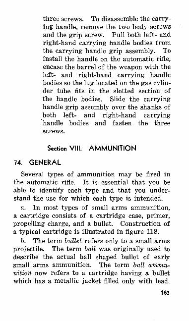
three screws. To disassemble the carry ing handle, remove the two body screws and the grip screw. Pull both left- and right-hand carrying handle bodies from the carrying handle grip assembly. To install the handle on the automatic rifle, encase the barrel of the weapon with the left- and right-hand carrying handle bodies so the lug located on the gas cylin der tube fits in the slotted section of the handle bodies. Slide the carrying handle grip assembly over the shanks of both left- and right-hand carrying handle bodies and fasten the three screws.
Section VIII. AMMUNITION
74. GENERAL
Several types of ammunition may be fired in the automatic rifle. It is essential that you be able to identify each type and that you under stand the use for which each type is intended.
a. In most types of small arms ammunition, a cartridge consists of a cartridge case, primer, propelling charge, and a bullet. Construction of a typical cartridge is illustrated in figure 118.
b. The term bullet refers only to a small arms projectile. The term ball was originally used to describe the actual ball shaped bullet of early small arms ammunition. The term ball ammu nition now refers to a cartridge having a bullet which has a metallic jacket filled only with lead.
163
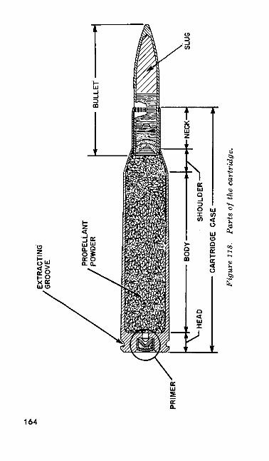
PRIM
ER
EXTR
ACTI
NG
'GR
OO
VE
SLUG
SHO
ULD
ER•
CA
RTR
IDG
E C
ASE
——
—
Fig
ure
118.
P
arts
of t
he c
artr
idge
.
c. The following types and models of caliber .30 cartridges are authorized for use in the auto matic rifle:
Ball, M2Tracer, MlArmor piercing, M2Incendiary, MlArmor piercing incendiary, M14Blank, M1909Dummy
75. CLASSIFICATIONBased on use, the principal classifications of
the several types of ammunition used with your automatic rifle are—
a. Ball M2—for use in marksmanship training and field firing problems.
b. Tracer Ml—for designating targets and for incendiary arid signaling purposes.
c. Armor Piercing M2—for use against lightly armored vehicles, protective shelters, and per sonnel.
d. Incendiary Ml—for use against inflam mable material.
e. Armor Piercing Incendiary M14—for use in place of either the armor piercing or incendi ary cartridges.
/. Blank Ml 909—for simulated fire.g. Dummy—for training.
165
76. LOT NUMBERa. When ammunition is manufactured, it is
given an ammunition lot number. This lot num ber is marked on all packing containers and placed on the identification card inclosed in the packing box. The lot number is used for all ammunition records and reports, including re ports of ammunition malfunction or accidents.
b. It is impractical to mark the ammunition lot number on each individual cartridge. There fore, every effort must be made to maintain the identity of the ammunition once the cartridges have been removed from their original container. Cartridges that have been removed from their original packing and for which the ammunition lot number has been lost are automatically placed in grade 3 and cannot be fired.
77. IDENTIFICATION
a. Markings. The contents of original boxes may be readily identified by the markings on the box. Similar markings on the label of the card board carton identify the contents of each carton. The markings appearing on the box and carton are complete information necessary for identi fication, shipping, care, handling, and use.
b. Identification of Ammunition Types. All types of caliber .30 automatic rifle ammunition are of the same shape and size. For easy recog nition, all ammunition types, except ball ammuni tion, bear certain identifying marks. Ball am-166
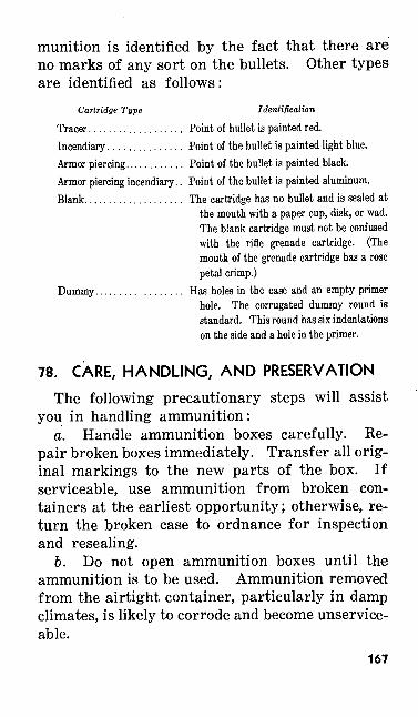
munition is identified by the fact that there are no marks of any sort on the bullets. Other types are identified as follows:
Cartridge Type Identification
Tracer................... Point of bullet is painted red.Incendiary............... Point of the bullet is painted light blue.Armor piercing............ Point of the bullet is painted black.Armor piercing incendiary.. Point of the bullet is painted aluminum.Blank.................... The cartridge has no bullet and is sealed at
the mouth with a paper cup, disk, or wad. The blank cartridge must not be confused with the rifle grenade cartridge. (The mouth of the grenade cartridge has a rose petal crimp.)
Dummy.................. Has holes in the case and an empty primerhole. The corrugated dummy round is standard. This round has six indentations on the side and a hole in the primer.
78. CARE, HANDLING, AND PRESERVATION
The following precautionary steps will assist you in handling ammunition:
a. Handle ammunition boxes carefully. Re pair broken boxes immediately. Transfer all orig inal markings to the new parts of the box. If serviceable, use ammunition from broken con tainers at the earliest opportunity; otherwise, re turn the broken case to ordnance for inspection and resealing.
b. Do not open ammunition boxes until the ammunition is to be used. Ammunition removed from the airtight container, particularly in damp climates, is likely to corrode and become unservice able.
167
c. Be especially careful not to strike the primer. A sharp blow on the primer may explode the cartridge.
d. Protect ammunition from mud, sand, and water. If the ammunition gets wet or dirty, wipe it off at once with a clean, dry cloth. Light cor rosion should be wiped off as soon as it is dis covered. Heavily corroded cartridges must be turned in.
e. During training, do not fire any caliber .30 ammunition until it has been identified by an ammunition lot number and grade to determine if that particular lot and grade of ammunition is safe for firing.
/. Do not expose ammunition to the direct rays of the sun. If the powder is heated, exces sive pressure may be developed when the weapon is fired. Do not store ammunition near radiators, hot water pipes, or other sources of heat. Heat not only deteriorates ammunition but also creates a fire hazard.
g. Do not oil or grease ammunition. Oil or grease collects dust, dirt, or other abrasives that are harmful.
h. Do not attempt to fire cartridges that are corroded or have bad dents, scratches, or loose bullets. If you think a cartridge is defective, turn it in. Do not attempt to destroy or throw away defective ammunition yourself.
79. STORAGEWhenever practicable, store small arms ammu
nition under cover. If it is necessary to leave168
this ammunition in the open, raise it at least six inches from the ground and cover it with a double thickness of tarpaulin. The tarpaulin should be in such a position as to offer maximum protec tion and yet allow free circulation of air. Dig trenches to prevent water from flowing under the ammunition pile.
80. BALLISTIC DATAThe approximate maximum range and average
muzzle velocity of the different types of caliber .30 ammunition authorized for use in the auto matic rifle are—
Average muzzleMaximum range relocities
Cartridge (yards) (feet per second)
Ball,M2......................... 3,500 2,800Tracer, Ml....................... 3,350 2,750Incendiary, Ml................... 2,875 3,020Armor piercing, M2............... 3,160 2,770Armor piercing incendiary, MH..... 3,300 2,830
81. PRECAUTIONS IN FIRING BLANK AMMU NITION
Never fire blank cartridges at men less than 20 yards away. Misfires in which the primer ex plodes but fails to ignite the powder charge may prove dangerous when blank ammunition is being fired. In this type of misfire, some of the un- burned powder may be left in the bore of the weapon. A series of such rounds in which the powder fails to ignite (because of moisture or other causes) may result in serious damage when
169
the accumulated powder is ignited by a subsequent cartridge. When misfires in excess of 5 percent are encountered in blank ammunition, the lot is withdrawn and reported to the ordnance officer.
82. PRECAUTIONS IN FIRING SERVICE AMMU NITION
The general precautions concerning the firing and handling of ammunition in the field, as pre scribed in SR 385-310-1 and TM 9-1900, are ob served. Precautions that apply particularly to small arms ammunition are—
a. Do not fire any small arms ammunition (other than blank ammunition) until it has been positively identified by ammunition lot number and grade. Under no circumstances will small arms ammunition graded and marked "For train ing use only" be fired over the heads of troops. - b. Do not use armor piercing cartridges in demonstrations in which tanks are used. In using armor piercing ammunition, remember that the cores of bullets that fail to penetrate the target may rebound. The radius of rebound for caliber .30 armor piercing ammunition depends on sev eral factors but may safely be assumed to be a maximum of 100 yards.
c. Before firing, make sure that the bore of your weapon is free from any foreign matter like cleaning patches, mud, sand, snow, and the like. A weapon fired with any obstruction in the bore may be damaged and may injure the automatic rifleman. If a bullet lodges in the bore of an automatic rifle, remove it by applying pressure170
from the muzzle end of the weapon. To attempt to force the bullet out by firing another cartridge is dangerous and is prohibited.
83. HANGFIRESSometimes a cartridge will not fire as soon as
the primer is struck by the firing pin. This is known as a hangfire. When a hangfire occurs, do not use any more ammunition from that lot. Your commanding officer is required to report the lot number of the ammunition involved to the post ordnance officer.
947041°—51—12171
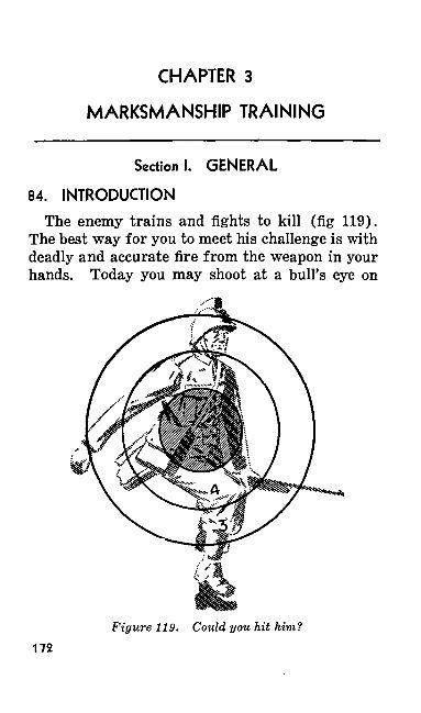
CHAPTER 3
MARKSMANSHIP TRAINING
Section I. GENERAL
84. INTRODUCTIONThe enemy trains and fights to kill (fig 119).
The best way for you to meet his challenge is with deadly and accurate fire from the weapon in your hands. Today you may shoot at a bull's eye on
Figure 119. Could you hit him?172
the known distance range. Tomorrow the target may be a fanatical aggressor attempting to kill you. Either you shoot him or he will shoot you. You must be prepared to fire quickly and accur ately at ranges that will vary from a few feet to several hundred yards. Your automatic rifle forms the base of fire for the rifle squad. Let it do its job properly. The man who is calm, col lected, and not excited or under tension is the best shot.
85. FUNDAMENTALSa. Learning to shoot is interesting; it is also
a challenge to your ability. Gain confidence in your weapon and you will gain confidence in your self. You must accept the methods of becoming a good marksman as taught by those who have had years of experience. No special ability or aptitude is necessary to learn how to shoot well. Good shots are not born with the ability to shoot well. They become good shots only after they have been given the fundamentals and have worked hard learning them. The only require ment is the desire to learn and the drive to ac complish that desire.
b. Good shooting is nothing but the'simple and complete mastery of five important principles. These principles are—
(1) Correct aiming.(2) Correct position.(3) Correct sight setting and trigger ma
nipulation.(4) Correct magazine changing.(5) Correct sight adjustments.
173
c. The five principles are listed in the order in which they are taught. Much stress is placed on that order. Just as you learned to crawl before you walked and walked before you ran, so must you learn the principles of marksmanship step by step. Each succeeding step depends on ma terial covered in the preceding steps.
86. PHASES OF TRAININGa. Marksmanship training is divided into a
preparatory marksmanship training phase and a range firing phase.
b. Preparatory marksmanship is subdivided into separate instructional steps. Range firing includes all firing, whether on the 1,000-inch range, the larger known distance range, the tran sition range, or others. One very important thing to remember during all phases of marksmanship training is that training is progressive. Each phase involves material covered in earlier phases.
c. Several guides are observed while teaching marksmanship training. These guides are—
(1) You must become skillful in mechanical training before you receive instruction in preparatory marksmanship training.
(2) Before firing on the range, you must have a thorough course in preparatory marksmanship training. This applies to all individuals, regardless of their pre vious qualification.
174
Section II. PREPARATORY'MARKSMANSHIP TRAINING
87. PURPOSE OF PREPARATORY MARKSMAN SHIP TRAINING
Preparatory marksmanship training teaches you good shooting habits and conditions you phys ically and mentally for accurate firing on the range. In combat, there are many factors that affect your shooting. Your target will be firing back at you.just as intently as you are firing at it. The target probably will be hard to see. To hit it, you must estimate its range to know where to aim or how to set your sights. Sometimes your shots will be fired hastily. By learning and prac ticing good shooting habits until they become second nature, you will give yourself an advantage when it comes to the showdown.
88. STEPS IN TRAINING
a. Preparatory marksmanship training is di vided into these six instructional steps—
(1) Sighting and aiming exercises.(2) Position exercises.(3) Sight setting and trigger manipulation
exercises.(4) Automatic fire exercises.(5) Sight changes, battle sight, effect of
the wind, and score card.(6) Examination.
b. The material covered in each step is based on all that was learned in preceding steps. All
175
steps, except the fifth one, must be presented in the order listed above. The fifth step may be taught any time between the first step and the last one. It may be taught either indoors or out doors and it is, therefore, an excellent subject for indoor training during bad weather.
89. DUTIES OF THE COACHa. Throughout all of your preparatory marks
manship training you will be coached. If enough trained men are available, your coach will be an experienced noncommissioned officer. Otherwise, you and the other men in your group receiving the training will be divided into four-man instruc tional groups. In this group, each man will at different times be a firer and a coach.
b. When serving as a coach, you are expected to supervise your firer carefully, for his success depends largely on how well you do your job. Re member that a good coach requires his firer to be perfect. You can see the mistakes your firer is making better than he can, so do not be easy on him. The success of your squad or platoon may very well depend on how well you train him.
c. These are some of the duties of a coach. Make sure that the firer—
(1) Blackens his sights.(2) Properly adj usts his gun sling.(3) Takes his position correctly.(4) Holds his breath while aiming and
pressing the trigger.(5) Takes careful aim.(6) Takes up trigger slack promptly.
176
(7) Presses the trigger properly.(8) Follows through and does not flinch.(9) Calls his shots.
(10) Observes safety precautions.
90. SIGHTING AND AIMING EXERCISESa. General. Sighting and aiming is taught
in three exercises. Each of these three exercises prepares you for good shooting.
(1) First exercise—Learning correct sight alinement and correct sight picture by using the sighting and aiming bar.
(2) Second exercise — Learning correct sight alinement and correct sight pic ture by using the automatic rifle.
(3) Third exercise—Checking your ability to make the correct sight alinement and correct sight picture by making and marking three sight pictures giving you a shot group.
b. Equipment. The following equipment is used by each instructional group (4 men) in sighting and aiming exercises:
(1) Sighting bar.(2) Automatic rifle.(3) Automatic rifle rest (ammunition box).(4) Aiming box (ammunition box).(5) 3-inch diameter aiming disk.(6) Pencil and paper.
Note. For details on constructing the equipment listed in b (1) (5) above, see paragraphs 223-230.
177
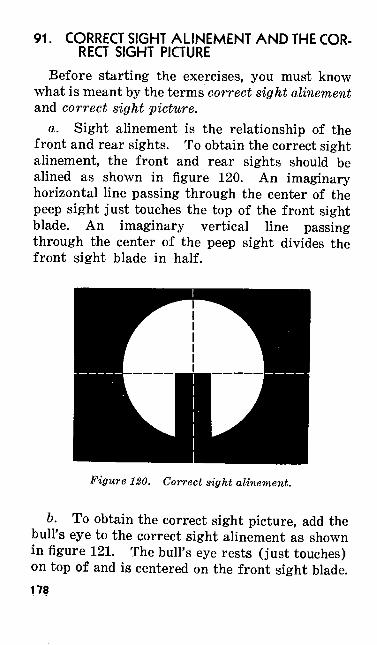
91. CORRECT SIGHT ALINEMENT AND THE COR RECT SIGHT PICTURE
Before starting the exercises, you must know what is meant by the terms correct sight alinement and correct sight picture.
a. Sight alinement is the relationship of the front and rear sights. To obtain the correct sight alinement, the front and rear sights should be alined as shown in figure 120. An imaginary horizontal line passing through the center of the peep sight just touches the top of the front sight blade. An imaginary vertical line passing through the center of the peep sight divides the front sight blade in half.
Figure 120. Correct sight alinement.
b. To obtain the correct sight picture, add the bull's eye to the correct sight alinement as shown in figure 121. The bull's eye rests (just touches) on top of and is centered on the front sight blade.178
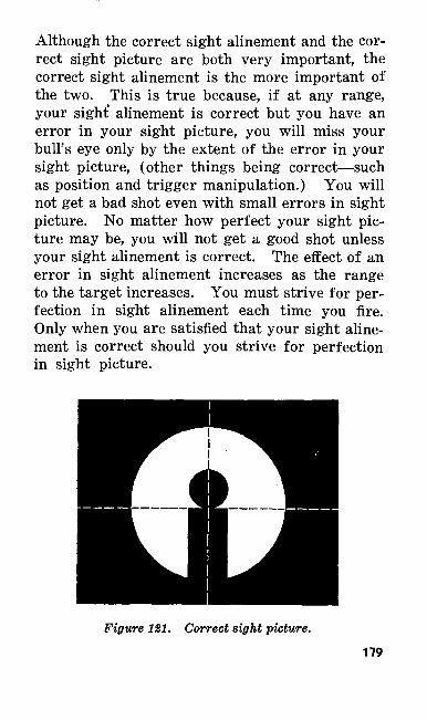
Although the correct sight alinement and the cor rect sight picture are both very important, the correct sight alinement is the more important of the two. This is true because, if at any range, your sight' alinement is correct but you have an error in your sight picture, you will miss your bull's eye only by the extent of the error in your sight picture, (other things being correct—such as position and trigger manipulation.) You will not get a bad shot even with small errors in sight picture. No matter how perfect your sight pic ture may be, you will not get a good shot unless your sight alinement is correct. The effect of an error in sight alinement increases as the range to the target increases. You must strive for per fection in sight alinement each time you fire. Only when you are satisfied that your sight aline ment is correct should you strive for perfection in sight picture.
Figure 121. Correct sight picture.179
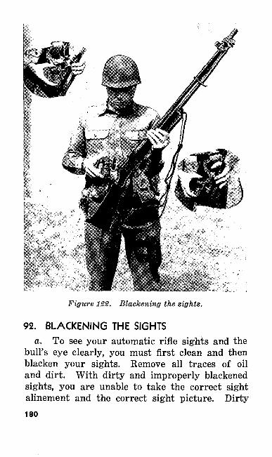
Figure 122. Blackening the sights.
92. BLACKENING THE SIGHTSa. To see your automatic rifle sights and the
bull's eye clearly, you must first clean and then blacken your sights. Remove all traces of oil and dirt. With dirty and improperly blackened sights, you are unable to take the correct sight alinement and the correct sight picture. Dirty180
sights cause you to aim low, because the bull's eye rests on top of the dirt rather than squarely on top of the front sight. Clean and blackened sights stand out clearly and are easy to see. Sights that are clean but not blackened are shiny and difficult to see. Figure 122 shows an automatic rifleman blackening his front and rear sights with a car bide lamp. Hold the point of the flame for a few seconds against the front and rear sights and against the barrel near the front sight. Place a uniform coating of blacking on the metal.
b. The best way to blacken the sights is to use a carbide lamp. If this lamp is not available, you can use a kerosene lamp, candle, small pine stick, smudge pot, or even matches.
c. An effective sight blacking preparation may be mixed by adding powdered lamp black to di luted white shellac. The quantity of lamp black used is small in proportion to the total quantity of shellac and is best determined by experiment. This black shellac is applied to the sights with a small varnish brush. The preparation dries rapidly.
93. FIRST SIGHTING AND AIMING EXERCISEa. The Sighting and Aiming Bar. The sight
ing and aiming bar is used in this exercise. The front and rear sights on the sighting and aiming bar represent the front sight post and the rear peep sight of your automatic rifle. The rear sight on the sighting bar is movable. This al lows you to make various adjustments in sight alinement. There is no part on the automatic
181
rifle that corresponds to the eyepiece on the sight ing and aiming bar. The eyepiece represents the position of your eye as you adjust the sights, and anyone who looks through the eyepiece sees the same sight alinement and sight picture that you see. The sighting and aiming bar is valuable in that its large size magnifies any errors in your sight alinement and sight picture.
b. Setting Up the Correct Sight Alinement. In the first sighting and aiming exercise, you learn and practice correct sight alinement and correct sight picture. Using the sighting and aiming bar, the coach sets up the correct sight alinement and hands the bar to the members of his group for examination. The coach points out the correct position of the front sight within the rear peep sight. Then each group member dem onstrates his ability to set up the correct sight alinement on the sighting and aiming bar. The coach closely checks each setting made and re quires the pupil to correct any errors discovered. As soon as all members of the group have dem onstrated their ability to make the correct sight alinement, the coach sets up slight errors in sight alinement on the sighting and aiming bar. Then each member of the group locates and corrects the errors in sight alinement. The coach checks to see that everyone has made the necessary cor rections.
c. Setting Up the Correct Sight Picture. When all members of the group are thoroughly familiar with the correct sight alinement, the correct sight picture is studied. The coach sets182
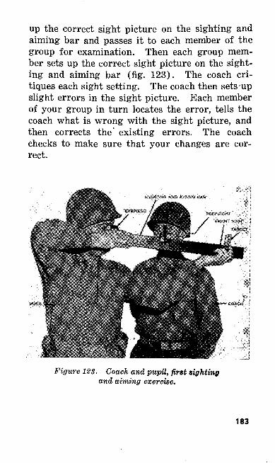
up the correct sight picture on the sighting and aiming bar and passes it to each member of the group for examination. Then each group mem ber sets up the correct sight picture on the sight ing and aiming bar (fig. 123). The coach cri tiques each sight setting. The coach then sets-up slight errors in the sight picture. Each member of your group in turn locates the error, tells the coach what is wrong with the sight picture, and then corrects the existing errors. The coach checks to make sure that your changes are cor rect.
Figure 123. Coach and pupil, first sighting and aiming exercise.
183
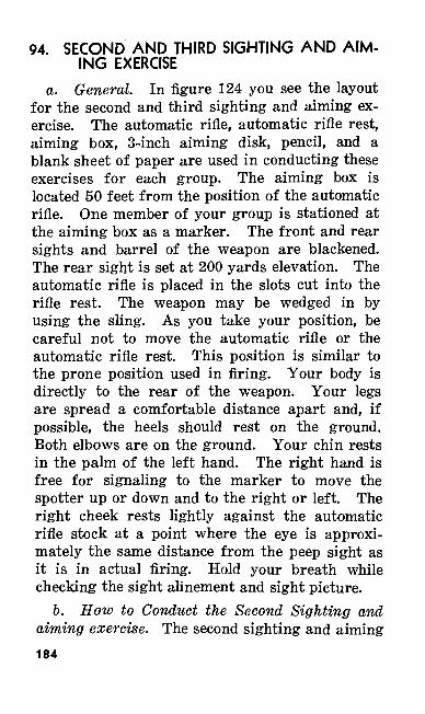
94. SECOND AND THIRD SIGHTING AND AIM ING EXERCISE
a. General. In figure 124 you see the layout for the second and third sighting and aiming ex ercise. The automatic rifle, automatic rifle rest, aiming box, 3-inch aiming disk, pencil, and a blank sheet of paper are used in conducting these exercises for each group. The aiming box is located 50 feet from the position of the automatic rifle. One member of your group is stationed at the aiming box as a marker. The front and rear sights and barrel of the weapon are blackened. The rear sight is set at 200 yards elevation. The automatic rifle is placed in the slots cut into the rifle rest. The weapon may be wedged in by using the sling. As you take your position, be careful not to move the automatic rifle or the automatic rifle rest. This position is similar to the prone position used in firing. Your body is directly to the rear of the weapon. Your legs are spread a comfortable distance apart and, if possible, the heels should rest on the ground. Both elbows are on the ground. Your chin rests in the palm of the left hand. The right hand is free for signaling to the marker to move the spotter up or down and to the right or left. The right cheek rests lightly against the automatic rifle stock at a point where the eye is approxi mately the same distance from the peep sight as it is in actual firing. Hold your breath while checking the sight alinement and sight picture.
b. How to Conduct the Second Sighting and aiming exercise. The second sighting and aiming184
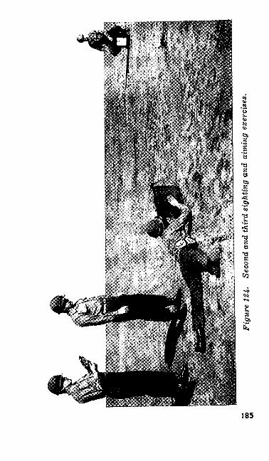
00
Ul
Figu
re 1
24.
Seco
nd a
nd th
ird
sigh
ting
and
aim
ing
exer
cise
s.
exercise starts with your coach setting up the correct sight picture. He assumes the correct position and, using his right hand, signals the marker (one member of the instructional group) to move the spotter up or down and to the right or left until the correct sight picture is obtained. The coach then commands HOLD to the marker and rises to his feet. He directs each member of his group to assume the correct position and to examine the sight picture. Next, each of you, in turn, demonstrates your ability to set up the cor rect sight picture. The coach checks the sight pictures. If there are any errors, he has them corrected. The marker offsets the spotter as soon as each of you completes the exercise. In the final phase of the second sighting and aiming exer cise, the coach sets up a slight error in the sight pictures. You are required to locate and correct the error. The coach checks to make sure that your changes are correct.
95. THIRD SIGHTING AND AIMING EXERCISEa. General. The third sighting and aiming
exercise is similar to the second exercise with the exception that three sight pictures are plotted by each group member. The purpose of this exer cise is to test your ability in setting-up the cor rect sight picture as well as to continue your in struction on sighting and aiming.
b. How to Conduct the Third Sighting and Aiming Exercise. Assume your position behind the weapon and direct the marker to move the spotter to set up the correct sight picture as you186
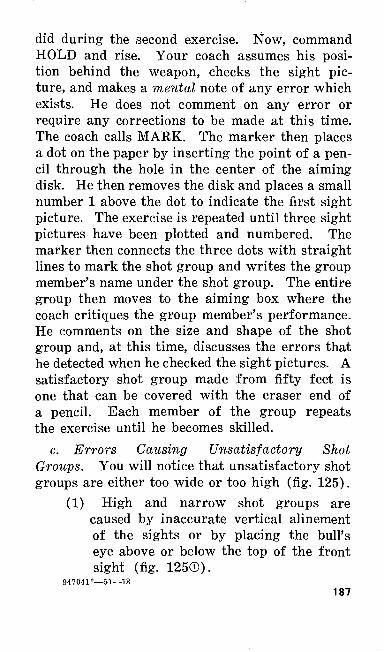
did during the second exercise. Now, command HOLD and rise. Your coach assumes his posi tion behind the weapon, checks the sight pic ture, and makes a mental note of any error which exists. He does not comment on any error or require any corrections to be made at this time. The coach calls MARK. The marker then places a dot on the paper by inserting the point of a pen cil through the hole in the center of the aiming disk. He then removes the disk and places a small number 1 above the dot to indicate the first sight picture. The exercise is repeated until three sight pictures have been plotted and numbered. The marker then connects the three dots with straight lines to mark the shot group and writes the group member's name under the shot group. The entire group then moves to the aiming box where the coach critiques the group member's performance. He comments on the size and shape of the shot group and, at this time, discusses the errors that he detected when he checked the sight pictures. A satisfactory shot group made from fifty feet is one that can be covered with the eraser end of a pencil. Each member of the group repeats the exercise until he becomes skilled.
c. Errors Causing Unsatisfactory Shot Groups. You will notice that unsatisfactory shot groups are either too wide or too high (fig. 125).
(1) High and narrow shot groups are caused by inaccurate vertical alinement of the sights or by placing the bull's eye above or below the top of the front sight (fig. 125©).
947041°—51—13187
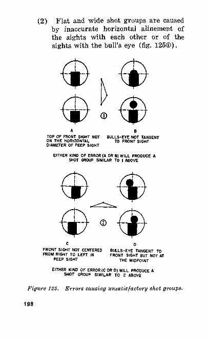
(2) Flat and wide shot groups are caused by inaccurate horizontal alinement of the sights with each other or of the sights with the bull's eye (fig. 125®).
TOP OF FRONT SIGHT NOT ON THE HORIZONTAL DIAMETER OF PEEP SIGHT
BULLS-EVE NOT TANGENT TO FRONT SIGHT
EITHER KINO OF ERROR (A OR B) WILL PRODUCE A SHOT GROUP SIMILAR TO 1 ABOVE
FRONT SIGHT NOT CENTERED FROM RIGHT TO LEFT IN
PEEP SIGHT
BULLS-EYE TANGENT TO FRONT SIGHT BUT NOT AT
THE MIDPOINT
EITHER KIND OF ERROR (C OR D) WILL PRODUCE A SHOT GROUP SIMILAR TO 2 ABOVE
Figure 125. Errors causing unsatisfactory shot groups.
188
(3) A shot group both high and wide is caused by a combination of the errors listed above.
96. POSITION EXERCISESa. General. Position exercises are the most
important phase of automatic rifle preparatory marksmanship training. After the first shot of a burst, you are unable to keep the correct sight alinement and sight picture. Therefore, so that you can continue hitting your target with all the shots in a burst, you must be in a proper firing position. The automatic rifle is fired from the prone, kneeling, sitting, aerial target, and crouch positions. As the prone position is the most stable position, use it whenever possible. You must be taught the use of the gun sling, the hinged butt plate, proper breathing, and the adjustment of the bipod legs before you practice the different positions.
b. Equipment. For position exercises it is de sirable that one automatic rifle be available for every two men and one aiming stake for every 12 men.
97. USE OF THE SLINGYou use the gun sling in the sitting, kneeling,
and crouch positions to help you support the au tomatic rifle. Do not use it in the prone and aerial target positions. Adjust the sling to give you firm support without discomfort. The three authorized sling adjustments are the loop sling, the hasty sling, and a special adjustment for the
189
crouch position. The hasty sling can be adjusted more quickly than the loop sling, but it does not give as much support. The loop and hasty sling adjustments for the modified leather sling and the loop and hasty sling adjustments for the web sling are different. The special adjustment of the leather sling for the crouch position is covered in paragraph 114. The web sling is considerably shorter than the leather sling. Therefore, when the automatic rifle is equipped with the web sling, the weapon is carried higher in the crouch posi tion, than shown in figure 141. Some men may have difficulty in assuming the crouch position using the web sling and may find it advantageous to fire the automatic rifle from this position with out using the sling.
98. LOOP SLING ADJUSTMENT WITH MODIFIED LEATHER SLING
To make the loop sling adjustment with the modified leather sling—
a. Place the butt of the automatic rifle on your right thigh and cradle the weapon against the inside of your right forearm, sights to the right. Both of your hands are now free to adjust the sling. Loosen the lower loop by unhooking the lower hook and rehooking it near the lower sling swivel. This increases the length of the sling so that it does not interfere while you are assum ing the fire position (fig. 126©).
b. Disengage the feed end hook and allow this portion of the sling to hang free. Unhook the190
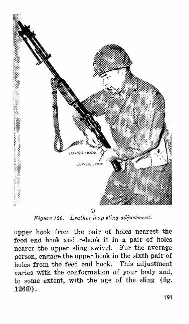
Figure 126. Leather loop sling adjustment.
upper hook from the pair of feed end hook and rehook it nearer the upper sling swivel person, engage the upper hook holes from the feed end hook, varies with the conformation to some extent, with the age 126®).
holes nearest the in a pair of holes
, For the average in the sixth pair of
, This adjustment of your body and,of the sling (fig.
191
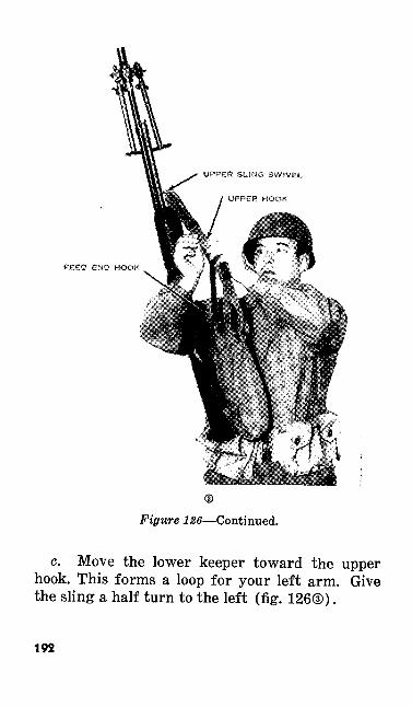
FEED END HOOK
Figure 126—Continued.
c. Move the lower keeper toward the upper hook. This forms a loop for your left arm. Give the sling a half turn to the left (fig. 126®).
192
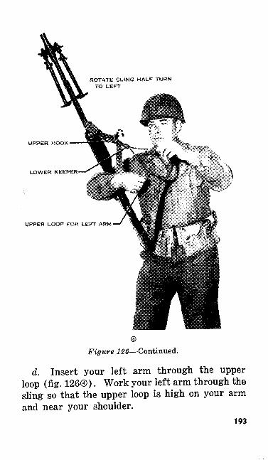
UPPER HOOK
LOWER KEEPER'
UPPER LOOP FOR LEFT ARM
Figure 126—Continued.
d. Insert your left arm through the upper loop (fig. 126®). Work your left arm through the sling so that the upper loop is high on your arm and near your shoulder.
193
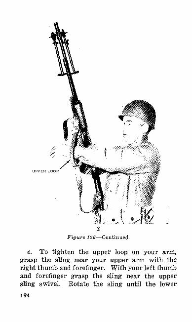
UPPER LOOP
Figure 126—Continued.
e. To tighten the upper loop on your arm, grasp the sling near your upper arm with the right thumb and forefinger. With your left thumb and forefinger grasp the sling near the upper sling swivel. Rotate the sling until the lower194
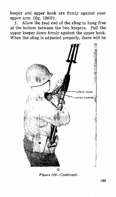
keeper and upper hook are firmly against your upper arm (fig. 126©).
/. Allow the feed end of the sling to hang free at the bottom between the two keepers. Pull the upper keeper down firmly against the upper hook. When the sling is adjusted properly, there will be
UPPER HOOK
LOWER KEEPER
Figure 126—Continued.195
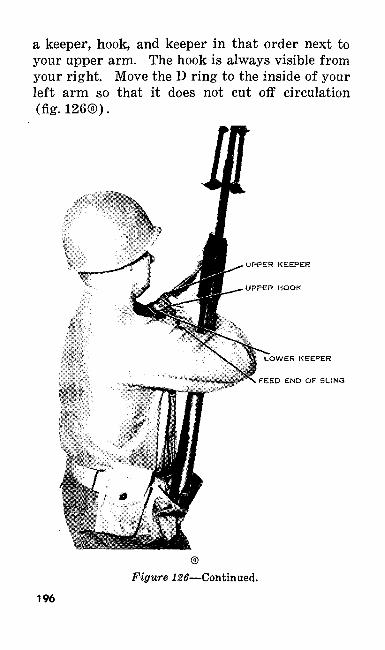
a keeper, hook, and keeper in that order next to your upper arm. The hook is always visible from your right. Move the D ring to the inside of your left arm so that it does not cut off circulation (fig. 126®).
UPPER KEEPER
UPPER HOOK
LOWER KEEPER
FEED END OF SUNG
Figure 126—Continued.
196
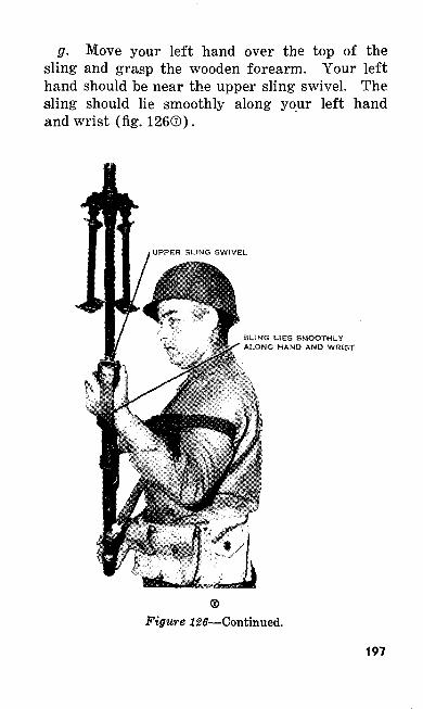
g. Move your left hand over the top of the sling and grasp the wooden forearm. Your left hand should be near the upper sling swivel. The sling should lie smoothly along your left hand and wrist (fig. 126©).
SUNG UES SMOOTHLY ALONG HAND AND WRfST
Figure 126—Continued.
197
99. LOOP SLING ADJUSTMENT WITH THE WEB SLING
To make the loop sling adjustment with the web sling—
a. Place the butt of the automatic rifle on your right thigh and cradle the weapon against the in side of your right forearm, sights to the right. Both of your hands are now free to adjust the sling. Unsnap the hook from the lower sling swivel. The loop to be used is formed by pulling the strap through the two slots of the buckle until it is large enough for your left arm. To do this, proceed as shown in figure 127©. Hold the buckle in your right hand and with your left hand grasp the sling between the buckle. Pull the sling out until a loop of the desired size is formed.
b. Hold the loop in your left hand and give the sling a half turn to the left.
c. Holding the buckle in your right hand, pass your left hand through the loop. The loop must be high and tight on your left arm. To tighten the loop on your arm, hold the automatic rifle with the right hand and move the left arm away from the weapon (fig. 127©).
d. With your left hand grasp the feed end of the sling and open the keeper. Pull the feed end of the sling toward the butt of the weapon until the proper sling adjustment is obtained (fig. 127®).
e. Move the keeper toward the butt of the automatic rifle until the keeper is out of the way of your left hand. Close the keeper. Pass the198
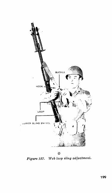
LOWER SLING SWIVEL
©Figure 127. Web loop sling adjustment.
199
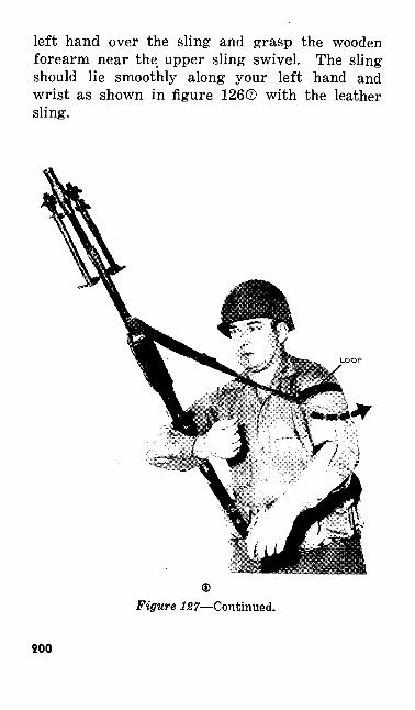
left hand over the sling and grasp the wooden forearm near the upper sling swivel. The sling should lie smoothly along your left hand and wrist as shown in figure 126© with the leather sling.
Figure 127—Continued.
200
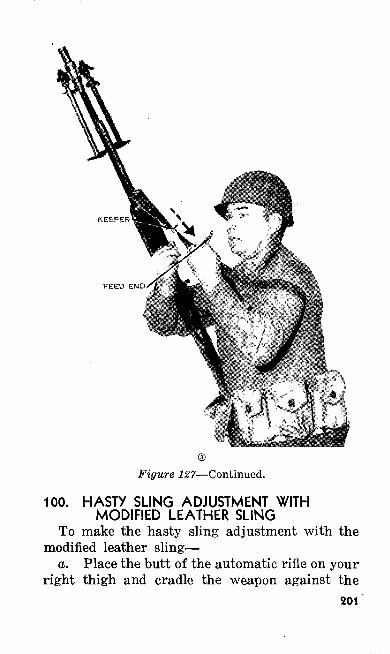
Figure 127—Continued.
100. HASTY SLING ADJUSTMENT WITH MODIFIED LEATHER SLING
To make the hasty sling adjustment with the modified leather sling—
a. Place the butt of the automatic rifle on your right thigh and cradle the weapon against the
201
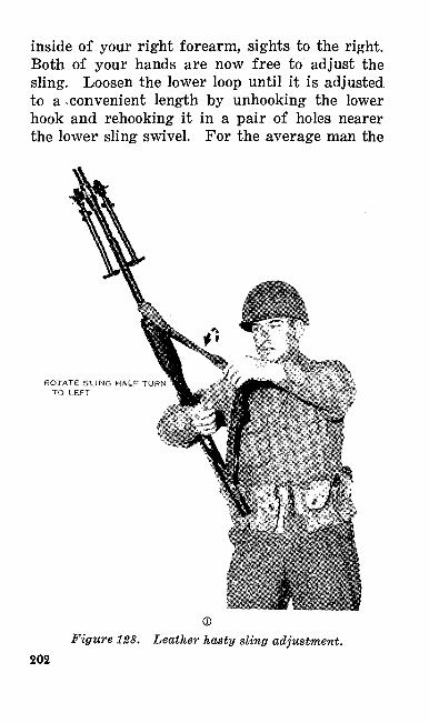
inside of your right forearm, sights to the right. Both of your hands are now free to adjust the sling. Loosen the lower loop until it is adjusted to a .convenient length by unhooking the lower hook and rehooking it in a pair of holes nearer the lower sling swivel. For the average man the
ROTATE SUNG HALF TURf TO LEFT
Figure 128. Leather hasty sling adjustment. 202
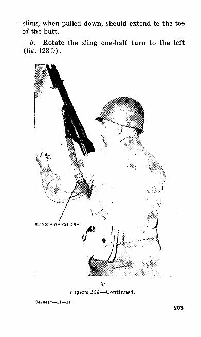
sling, when pulled down, should extend to the toe of the butt.
6. Rotate the sling one-half turn to the left (fig. 128®).
Figure 128—Continued.947041°—51—14
203
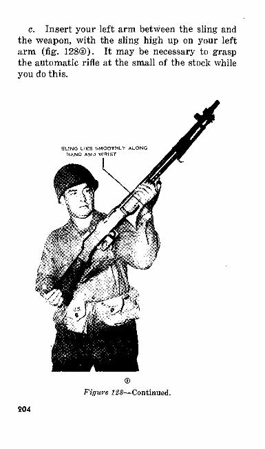
c. Insert your left arm between the sling and the weapon, with the sling high up on your left arm (fig. 128©). It may be necessary to grasp the automatic rifle at the small of the stock while you do this.
SLING LIES SMOOTHLY ALONG HAND AMD WRIST
204
Figure 128—Continued.
d. Pass your left hand under and then over the sling. Grasp the weapon at the wooden fore arm near the upper sling swivel. The sling should lie smoothly along your left hand and wrist (fig. 128®).
101. HASTY SLING ADJUSTMENT WITH THE WEB SLING
To make the hasty sling adjustment with the web sling—
a. Place the butt of the automatic rifle on your right thigh and cradle the weapon against the inside of the right forearm, sights to the right. Both of your hands are now free to adjust the sling. Open the keeper and move the keeper and feed end of the sling toward the upper sling swivel until sufficient slack is obtained in the sling for the hasty sling adjustment (fig. 129©). Close the keeper.
b. With your left hand give the sling a half turn to the left (fig. 129©).
c. Insert your left arm between the sling and the weapon with the sling high up on your left arm (fig. 129®). It may be necessary to grasp the automatic rifle at the small of the stock while you do this.
d. Pass your left hand under and then over the sling. Grasp the weapon at the wooden fore arm near the upper sling swivel. The sling should lie smoothly along your left hand and wrist (fig. 129©).
205
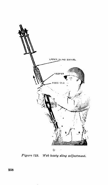
©Figure 129. Web hasty sling adjustment.
206
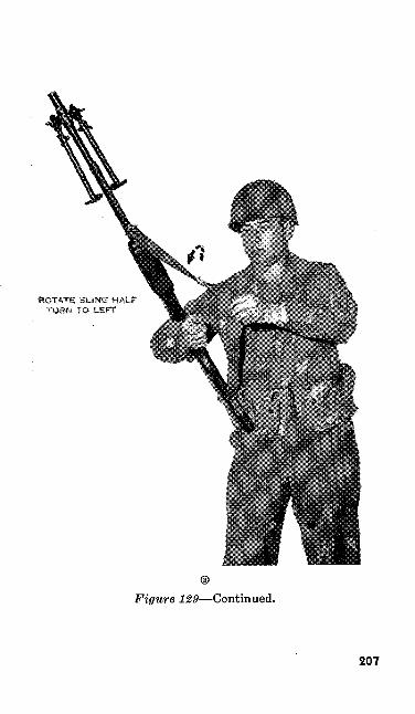
ROTATE SLING HALF TU«N TO LEFT
©
Figure 129—Continued.
207
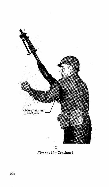
Figure 120—Continued.
208
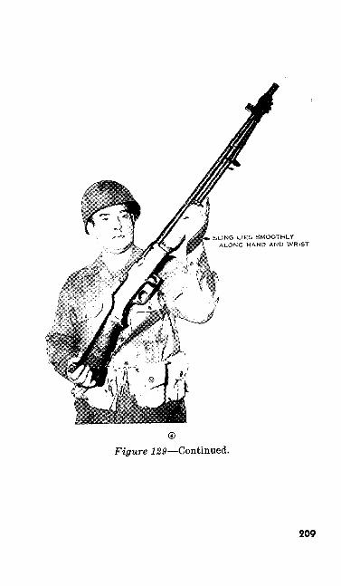
SLtNG LIES SMOOTMtY ALONG HAND AND WRIST
Figure 129—Continued.
209
102. HINGED BUTT PLATEThe hinged butt plate is always used in the
prone position. It should also be used in the sit ting and kneeling positions as it provides addi tional support. The hinged butt plate is placed on your shoulder and as near as possible to the junction of your neck and shoulder.
103. BIPOD ADJUSTMENTSa. Use the bipod only when firing from the
prone position. During preparatory marksman ship training, your coach adjusts the bipod legs to fit your size and position. To adjust the bipod—
(1) Lock the bipod legs into the bipod body, square shoulder to square shoulder, by tightening the upper bipod thumb screws. When the bipod legs are not adjusted square shoulder to square shoul der, the bipod group will collapse.
(2) Raise or lower the bipod legs so that the weapon points at the target. Tighten the lower bipod thumb screws to prevent the legs from shortening. Because the bipod is attached to the barrel with a swivel, it is not necessary normally to compensate for ground slope by making one leg longer than the other.
b. Before assuming the kneeling, sitting or aerial target positions, lock the bipod legs back against the barrel, square shoulder to square210
shoulder. This prevents the bipod group from swinging back and forth and interfering with your aim while you fire.
104. BREATHINGHolding your breath while aiming and pressing
off each shot is very important. You hold your breath to keep your weapon steady. The correct method for holding your breath is to take an ordi nary breath, let out a little, and hold the rest by closing the throat. When sighting, do not hold your breath so long that you become unsteady.
105. PROCEDURE FOR CONDUCTING POSITION EXERCISES
After explaining and demonstrating sling ad justments, breathing, and the firing positions, the instructor divides your group into pairs. One member of the pair acts as a coach, the other per forms the exercise. These positions are alter nated. Small bull's eyes painted at different heights on aiming stakes are used as aiming points.
106. PRONE POSITIONa. Before assuming the prone position, make
the following checks:(1) The sling. Make sure that it is loose
and out of the way of the magazine feed way. (The sling is not used in the prone position.)
211
(2) The gas cylinder assembly. It should be adjusted initially on the small gas port, and the gas cylinder lock should be pushed in. Learn here not to touch the barrel. It becomes very hot during fir ing.
(3) The bipod legs. They should be locked into the bipod body, square shoulder to square shoulder. During preparatory marksmanship training and the first part of range practice, the coach adjusts the bipod legs for the automatic rifleman.
(4) The flash hider. It should be tight. A loose flash hider causes a scattered shot group.
b. To assume the prone position, place the au tomatic rifle on the ground with the sights up and the muzzle pointing to your front. Aline your body directly to the rear of the weapon by stand ing at the butt end of your automatic rifle and facing down range. Take two steps directly to the rear. Sink down to your knees and into the prone position. Raise the hinged butt plate and place the butt end of the weapon to your shoulder (fig. 130). Spread your legs a comfortable dis tance apart keeping the heels down if possible. Raise the rear sight leaf.
c. Take the proper grip. Your right hand is in front of your left hand (fig. 131). In this po sition, place your right thumb over the small of the stock. Your right forefinger—any part of the finger from the tip to the second joint—is placed212
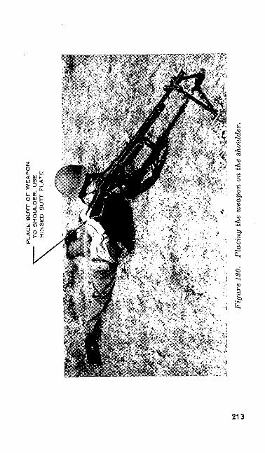
PLA
CE
BU
TT
OF
WE
AP
ON
T
O S
HO
ULD
ER
. U
SE
H
ING
ED
B
UT
T P
LA
TE
Fig
ure
ISO
. Pl
acin
g th
e w
eapo
n on
the
shou
lder
.
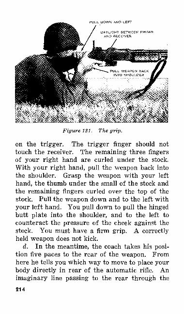
PULL DOWN AND LEFT
DAYLIGHT BETWEEN FINGER AND RECEIVER
Figure 131. The grip.
on the trigger. The trigger finger should not touch the receiver. The remaining three fingers of your right hand are curled under the stock. With your right hand, pull the weapon back into the shoulder. Grasp the weapon with your left hand, the thumb under the small of the stock and the remaining fingers curled over the top of the stock. Pull the weapon down and to the left with your left hand. You pull down to pull the hinged butt plate into the shoulder, and to the left to counteract the pressure of the cheek against the stock. You must have a firm grip. A correctly held weapon does not kick.
d. In the meantime, the coach takes his posi tion five paces to the rear of the weapon. From here he tells you which way to move to place your body directly in rear of the automatic rifle. An imaginary line passing to the rear through the214
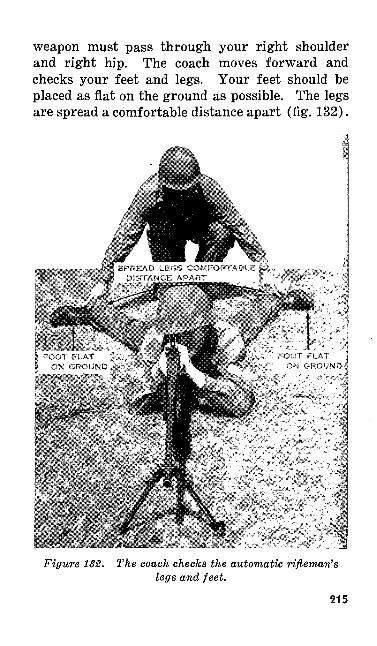
weapon must pass through your right shoulder and right hip. The coach moves forward and checks your feet and legs. Your feet should be placed as flat on the ground as possible. The legs are spread a comfortable distance apart (fig. 132).
Figure 132. The coach checks the automatic rifleman's legs and feet.
215
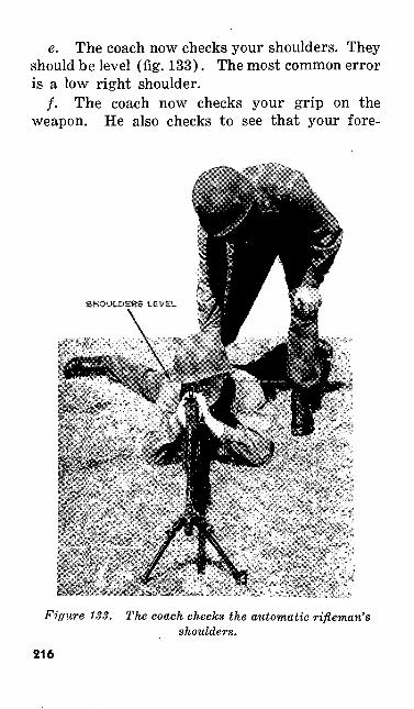
e. The coach now checks your shoulders. They should be level (fig. 133). The most common error is a low right shoulder.
/. The coach now checks your grip on the weapon. He also checks to see that your fore-
Figure 133. The coach checks the automatic rifleman's shoulders.
216
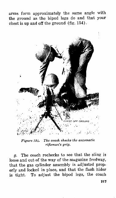
arms form approximately the same angle with the ground as the bipod legs do and that your chest is up and off the ground (fig. 134).
Figure 1S4- The coach checks the automatic rifleman's grip.
g. The coach rechecks to see that the sling is loose and out of the way of the magazine feedway, that the gas cylinder assembly is adjusted prop erly and locked in place, and that the flash hider is tight. To adjust the bipod legs, the coach
217
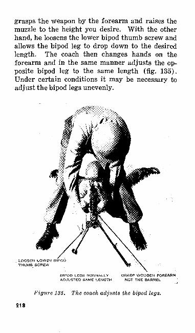
grasps the weapon by the forearm and raises the muzzle to the height you desire. With the other hand, he loosens the lower bipod thumb screw and allows the bipod leg to drop down to the desired length. The coach then changes hands on the forearm and in the same manner adjusts the op posite bipod leg to the same length (fig. 135). Under certain conditions it may be necessary to adjust the bipod legs unevenly.
LOOSEN LOWER BIPOD THUMB SCREW
BIPOD LEGS NORMALLY GRASP WOODEN FOREARM ADJUSTED SAME LENGTH NOT THE BARREL
Figure 135. The coach adjusts the bipod legs.
218
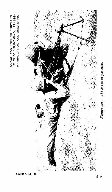
CO
AC
H
FA
R
EN
OU
GH
F
OR
WA
RD
T
O C
HE
CK
F
LIN
CH
ING
. T
RIG
GE
R
MA
NIP
UL
AT
ION
A
ND
B
RE
AT
HIN
G
Fig
ure
136,
Th
e co
ach
in p
ositi
on.
h. The coach moves to the rear and rechecks your position. He then assumes the coaching position. In this position, he is on your left far enough forward so that he can see your face. The coach rests on his left hip and left elbow (fig. 136).
107. ERRORS IN THE PRONE POSITIONBecause you will serve as a coach many times
during marksmanship training, you must be able to recognize and correct errors. Some of the more common errors found in the prone position are—
a. Body Not Directly to the Rear of the Weapon. This error is easily detected by standing directly to the rear of the automatic rifleman and observing the relationship of his body and the line of fire. To correct this error tell the automatic rifleman to move his body to the right or left as necessary.
b. Right Shoulder Too Low. To correct the error, move the right elbow in towards his body or the left elbow out and forward. It may be necessary to do both.
c. Chest on the Ground. This error results from the automatic rifleman's elbows being out too far. To correct this error he must move his elbows in until they form approximately the same angles with the group as the bipod legs.
108. KNEELING POSITIONa. The kneeling position is used frequently on
level ground or ground that slopes upward. It is a steady position and a good one when you do not220
have time to assume the prone position. In this position, use the hinged butt plate and the loop or hasty sling. In practicing this exercise, have your coach lock the bipod legs back along the bar rel, square shoulder to square shoulder.
b. To assume the kneeling position, stand fac ing the target. Do a right face and kneel on the right knee. As you go down in position, you should rotate over the right toe. Next, place the butt of the weapon to your shoulder and aim at the target (fig. 137© and®).
c. The following features must be observed in the kneeling position:
(1) Sit on the right heel so that there is solid contact between your right heel and right buttock. If at first this puts too much strain on the instep, dig a small hole for your toe. Practice in this posi tion eliminates the need for this hole.
(2) Keep the lower left leg vertical as viewed from the front.
(3) Point the toes of the left foot in the general direction of the target. Many expert automatic riflemen prefer to draw the left foot back and relax the body weight forward so that there is solid contact made between the calf of the left leg and the left thigh.
(4) Place the right knee so the right thigh forms an angle of approximately 90° to the line of aim. The entire surface of the right lower leg, from the knee to the toe, is in contact with the ground.
221
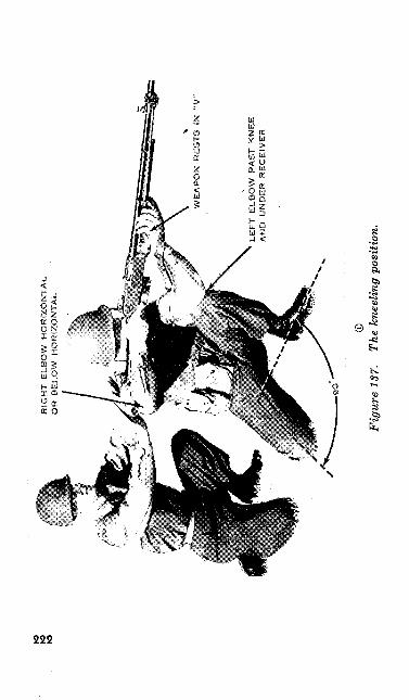
K3 IO
RIG
HT
ELB
OW
H
OR
IZO
NT
AL
OR
B
ELO
W
HO
RIZ
ON
TA
L
LE
FT
ELB
OW
PA
ST
KN
EE
A
ND
U
ND
ER
R
EC
EIV
ER
Fig
ure
1ST.
Th
e kn
eelin
g po
sitio
n.
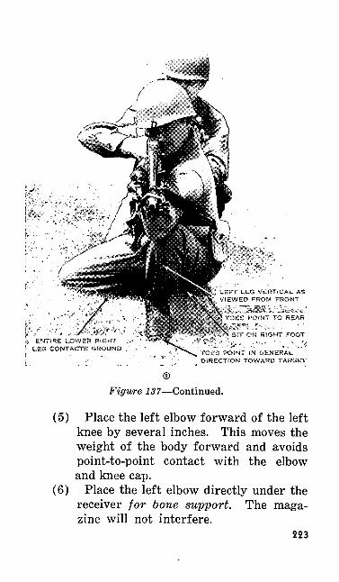
LEFT LEG VERTICAL AS VIEWED FROM FRONT
ES POINT TO REAR
IT ON RIGHT FOOT
TOES POINT !N GENERAL. DIRECTION TOWARD TARGET
Figure 137—Continued.
(5) Place the left elbow forward of the left knee by several inches. This moves the weight of the body forward and avoids point-to-point contact with the elbow and knee cap.
(6) Place the left elbow directly under the receiver for bone support. The maga zine will not interfere.
223
(7) Rest the automatic rifle in the V formed by the thumb and first finger and on the heel of the left hand.
(8) Keep the left wrist straight.(9) Keep the sling up high on the arm so
that daylight can be seen between the sling and the crook of the elbow.
(10) Relax the weight of the body forward over the left leg. This takes most of the weight off the right leg and puts it on the left leg.
(11) Place your cheek against the stock and your right thumb.
(12) After checking your position, your coach assumes his position, which is kneeling to your rear with his hands up ready to brace you in case of a runaway gun.
109. ERRORS IN THE KNEELING POSITIONThe errors found most frequently in the kneel
ing position and the ways to correct them are— a. Left Elboiv Not Under the Automatic
Rifle. Here the muscles and not the bones are supporting the automatic rifle. To correct this error, take the butt of the automatic rifle from your shoulder, move your left foot to the right, and then assume the correct position.
b. Elboiv and Knee Placed So As to Make Point-To-Point Contact. When the left elbow rides directly on the kneecap, it makes a very unsteady position. To correct this error, extend the left elbow beyond the left kneecap. This cor-224
rection shifts your weight forward and avoids point-to-point contact between the left elbow and left kneecap.
c. Right Thigh Not At a Right Angle to the Line of Aim. This position is very unstable as the three point base is reduced. To correct this error, move your right knee until an angle of approximately 90° is made with the line of aim.
d. Improper grip. To correct this error, place the weapon on your left hand so that it rests in the V formed by the thumb and forefinger and on the heel of the left hand.
110. ALTERNATE KNEELING POSITIONSa. If you have long legs, place your left foot
forward of the left knee. This lowers the knee. It is necessary to experiment to determine how far to move your left foot forward to bring the line of aim down on the bull's eye. Otherwise, the position is the same as the standard kneeling posi tion.
b. If you have short legs, place your left foot directly under the left elbow. In this position, the left leg is vertical as viewed from the side as well as from the front and the line of aim is raised to the highest position possible. Otherwise, your position and the position of your coach are the same as in the standard kneeling position.
111. SITTING POSITIONa. The sitting position is one of the easiest of
the firing positions to assume. It is suitable wher ever the grass is high or where there is anything
225
else that might obstruct the vision in the prone position. It is also suitable for firing downhill. With the exception of the prone position, the sit ting position is the steadiest one because you have a rest for both elbows. In this position, use the hinged butt plate and the loop or hasty sling. In practicing this exercise, have your coach lock the bipod legs back along the barrel, square shoul der to square shoulder.
b. To assume the sitting position, half face to the right, spread your feet a comfortable dis tance apart, and sit down. Break your fall by using the right hand and then move your but tocks to the rear until the under sides of the knees are about a hand's span off the ground. Bend forward from the waist and place the left upper arm on the flat portion of the shin bone of the left leg. There should be several inches of contact between the upper arm and the shin bone. Place the automatic rifle butt to your shoulder, take the correct grip on your weapon, and block your right elbow in front of the right knee. Relax your body into the sling (fig. 138© and ©).
c. The following features must be observed in the sitting position:
(1) Spread the legs a comfortable distance apart. The feet must be farther apart than the knees. Relax the feet forward and inward.
(2) Place the left upper arm so that there is contact for several inches between the flat part of the left shin and the left upper arm.
226
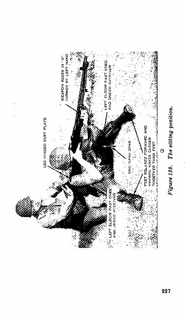
WE
AP
ON
R
ES
TS
IN
"V
" F
OR
ME
D
BY
L
EF
T H
AN
D
LE
FT
E
LB
OW
P
AS
T K
NE
E.
: •,
AN
D U
ND
ER
R
EC
EiV
ER
V
FE
ET
RE
LA
XE
D F
OR
WA
RD
A
ND
VI
INW
AR
D.
KN
EE
S C
LO
SE
RJ
TO
GE
TH
ER
TH
AN
F
EE
T
©
Figu
re 1
38.
The
sitti
ng p
ositi
on.
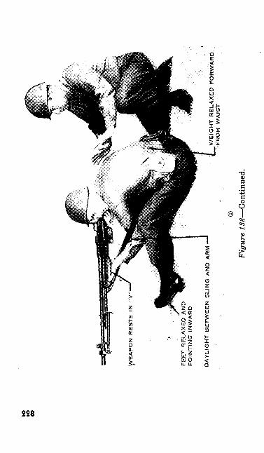
to K>
CO
FE
ET
RE
LA
XE
D A
ND
P
OIN
TIN
G
INW
AR
D
DA
YLIG
HT
BE
TW
EE
N S
LIN
G A
ND
AR
MW
EIG
HT
RE
LA
XE
D
FO
RW
AR
D.
FR
OM
W
AIS
T
©
Figu
re 1
38—
Con
tinue
d.

(3) Place your left elbow under the re ceiver. Be sure that the left wrist is straight.
(4) Rest the automatic rifle in the V of the left hand the same as for the kneeling position.
(5) Lean forward from the waist so that the weight of the upper part of the body is on both legs. Again, strive for bone support instead of muscle support to hold the weight of the upper part of your body.
(6) Place the right upper arm against the right shin. The right arm is placed slightly on the inside of the right leg to serve as a brace during firing.
(7) Keep the sling up high on the arm so that daylight can be seen between the sling and the crook of the elbow.
(8) Your grip is the same as in the kneeling position.
(9) Place your cheek against the stock and your right thumb.
(10) After checking your position, your coach assumes his position which is kneeling to your rear and with his hands up ready to brace you in case of a runa way gun.
229
112. ERRORS IN THE SITTING POSITIONThe errors found most frequently in the sitting
position and the ways to correct them are—a. Left Elbow Not Under the Automatic Rifle.
Here the muscles and not the bones are support ing the automatic rifle. To correct this error, take the butt of the automatic rifle from your shoulder and move your feet to the right.
b. Elbows and Knees Placed So As to Make Point-To-Point Contact. This error results in an unstable support for the automatic rifle and it places your body in a position which is too erect and unstable. To correct this error, lower your knees, bend your body well forward from the waist, and place the left upper arm well past the left knee and against the left shin. Block the right elbow in front of the right knee.
c. Knees Farther Apart Than Feet. This error may be caused by placing the feet too close to gether ; by turning the toes outward which throws the knees outward; and by pushing out, rather than down, against the shins with the elbows. This error causes muscular support rather than bone support. To correct this error, remove the weapon from your shoulder and stretch both legs out on the ground. The feet are separated from 20 to 30 inches depending on the length of your legs. Raise the left knee about one hand's span off the ground. Place the left upper arm along the top of the left shin. Place the hinged butt plate on the right shoulder. Assume the correct grip with the right hand. Lower the right elbow and raise the right knee until solid contact is230
made between the right upper arm and right shin. The right knee should be about one hand's span off the ground.
d. Toes Pointing Up. This error usually in dicates muscular tension in the legs and feet. To correct the error, relax the muscles in your legs and feet so that your toes point forward and in ward.
113. ALTERNATE SITTING POSITIONSIf you have unusually long legs or a short body
and short arms, you may find it difficult to assume the standard sitting position. You may have diffi culty in placing your arms in the correct position on the shins. In such cases, the instructor may authorize you to use one of two modified positions. Neither modified position will be used until you have been closely checked by the instructor.
a. In the Cross-Legged Modified Sitting Posi tion, sit with your left leg crossed over your right leg. Draw your feet up under you so that the outer part of the calf of each leg rests on the in side of the opposite foot. Support the back of the upper arms against the shin bones and very nearly at right angles to them. Otherwise your position and the position of your coach are the same as in the standard sitting position (fig. 139).
b. In the Cross-Ankled Modified Sitting Posi tion, sit with the left ankle crossed over the right ankle. The distance you extend your feet to the front depends upon the length of your legs. Take care to relax your legs; do not hold your knees up
231
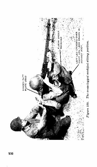
to
to
i"Y
Miir
»'•.
&<;
. :,•
•'.'.
•'
^K
^-;-
LE
FT
LE
G C
RO
SS
ED
OV
ER
• \
, R
IGH
T
LEG
- LE
GS
D
RA
WN
IN
;.
AG
AIN
ST
B
OD
Y.
Fig
ure
139.
Th
e cr
oss-
legg
ed m
odifi
ed s
ittin
g po
sitio
n.
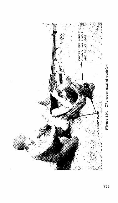
CR
OS
S
LE
FT
AN
KLE
-;
OV
ER
R
IGH
T A
NK
LE
'
AN
D
RE
LA
X
LEG
S
Fig
ure
140.
Th
e cr
oss-
ankl
ed p
ositi
on.
by sheer muscular effort. Support the upper arms against the shins as in the cross-legged position. The cross-ankled position provides only a two- point base of support. Therefore it is much less stable than either the standard sitting position or the cross-legged position which have a three-point base. If you weigh less than 170 pounds avoid this position. Otherwise your position and the position of your coach are the same as in the standard sitting position (fig. 140).
114. CROUCH POSITION
a. The crouch position is used for assault fire and, in an emergency, to engage targets at close range.
6. To make the special sling adjustment for the crouch position—
(1) Lengthen the sling to approximately its fullest length. This adjustment depends upon your height and the proper length for you can only be found by experiment ing.
(2) Pick the weapon up by the sling and place the sling over your head and on your left shoulder (fig. 141).
(3) Pass your left hand over the sling and grasp the forearm near the upper sling swivel, turning the weapon over, sights up.
(4) Place the rear end of the sling around the outside of the stock.
234
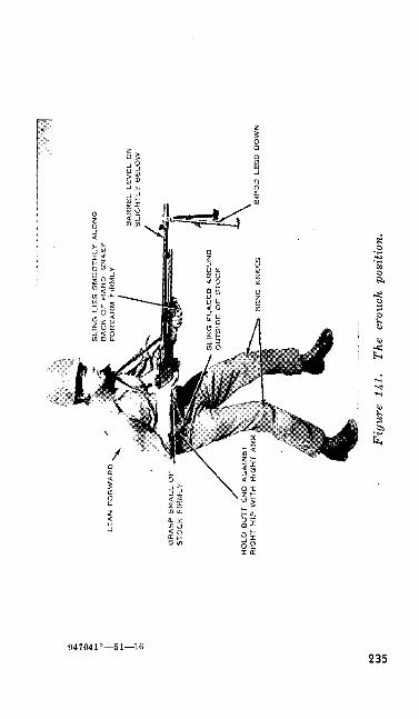
LE
AN
F
OR
WA
RD
GR
AS
P S
MA
LL
OF
S
TO
CK
F
IRM
LY
HO
LD
B
UT
T E
ND
A
GA
INS
T
RIG
HT
H!P
W!T
H
RiG
HT
AR
M
BA
RR
EL L
EV
EL
OR
S
LIG
HT
LY
B
EL
OW
BS
PO
D
LEG
S
DO
WN
Fig
ure
141.
Th
e cr
ouch
pos
ition
.
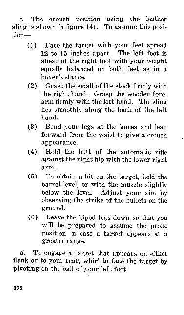
c. The crouch position using the leather sling is shown in figure 141. To assume this posi tion—
(1) Face the target with your feet spread 12 to 15 inches apart. The left foot is ahead of the right foot with your weight equally balanced on both feet as in a boxer's stance.
(2) Grasp the small of the stock firmly with the right hand. Grasp the wooden fore arm firmly with the left hand. The sling lies smoothly along the back of the left hand.
(3) Bend your legs at the knees and lean forward from the waist to give a crouch appearance.
(4) Hold the butt of the automatic rifle against the right hip with the lower right arm.
(5) To obtain a hit on the target, hold the barrel level, or with the muzzle slightly below the level. Adjust your aim by observing the strike of the bullets on the ground.
(6) Leave the bipod legs down so that you will be prepared to assume the prone position in case a target appears at a greater range.
d. To engage a target that appears on either flank or to your rear, whirl to face the target by pivoting on the ball of your left foot.
236
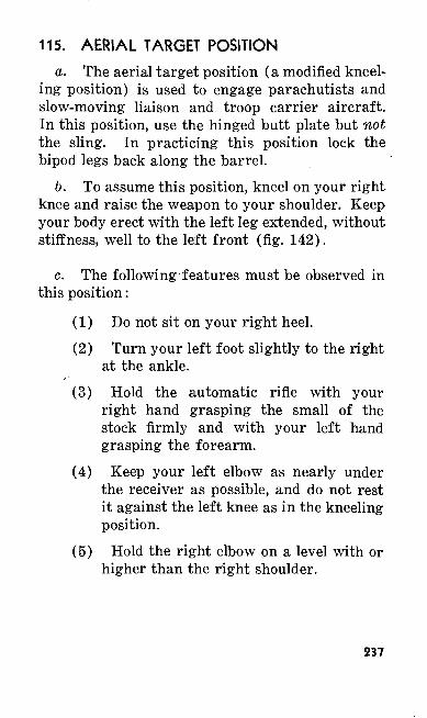
115. AERIAL TARGET POSITIONa. The aerial target position (a modified kneel
ing position) is used to engage parachutists and slow-moving liaison and troop carrier aircraft. In this position, use the hinged butt plate but not the sling. In practicing this position lock the bipod legs back along the barrel.
b. To assume this position, kneel on your right knee and raise the weapon to your shoulder. Keep your body erect with the left leg extended, without stiffness, well to the left front (fig. 142).
c. The following features must be observed in this position:
(1) Do not sit on your right heel.(2) Turn your left foot slightly to the right
at the ankle.(3) Hold the automatic rifle with your
right hand grasping the small of the stock firmly and with your left hand grasping the forearm.
(4) Keep your left elbow as nearly under the receiver as possible, and do not rest it against the left knee as in the kneeling position.
(5) Hold the right elbow on a level with or higher than the right shoulder.
237
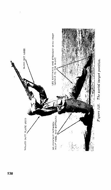
to CO
CO
HIN
GE
D
BU
TT
PLA
TE
U
SE
D
LE
G
EX
TE
ND
ED
A
ND
ST
RA
IGH
T W
ITH
F
OO
T
D
TO
T
HE
R
IGH
TN
O C
ON
TA
CT
B
ET
WE
EN
R
IGH
T
HE
EL
A
ND
B
UT
TO
CK
S
Fig
ure
H.2
. Th
e ae
rial
tar
get p
ositi
on.
116. SIGHT SETTING AND TRIGGER MANIPU LATION EXERCISES
a. General. Sight setting and trigger manip ulation are taught in three exercises. Each of these three exercises prepares you for good shoot ing—
(1) First exercise—Training in sight set ting.
(2) Second exercise—Training in trigger manipulation.
(3) Third exercise—Timed training in sight setting, aiming, and manipulating the trigger.
b. Equipment. In these exercises it is de sirable to have one automatic rifle for every two men and one 1,000-inch target, riflle, caliber .30 Ml for every four men.
117. THE REAR SIGHTTo learn sight setting, you must understand the
rear sight. On the rear sight assembly (fig. 143) there are two sights, an open or battle sight and a peep sight.
a. The open or battle sight is used when the sight leaf is down. This sight corresponds to the peep sight set at a range of 300 yards. The peep sight can be adjusted for different ranges (elevations) by moving the elevation gage until the peep sight index line is opposite the desired range graduation on the rear sight leaf. As you turn the elevation knob, you hear and feel it click. Sometimes the final adjustment click brings the
239
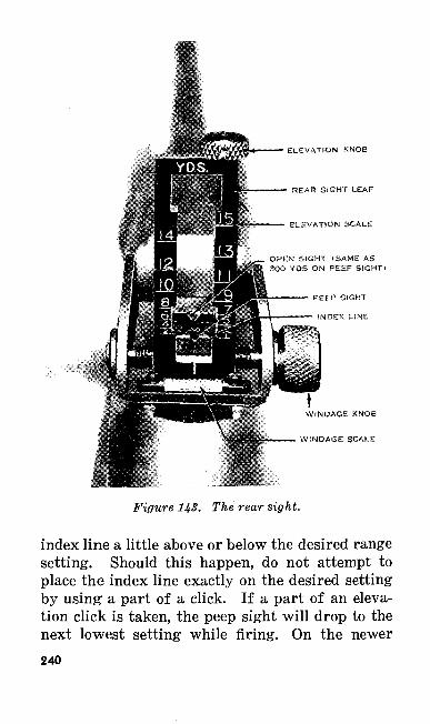
ELEVATION KNOE
REAR SIGHT LEAF
ELEVATfON SCALE
OPCN SIGHT <SAM£ AS 3QO YDS ON PEEP SiGHTt
PE£P SIGHT
INDEX UNE
WINDAGE KNOB
WINDAGE SCALE
Figure US. The rear sight.
index line a little above or below the desired range setting. Should this happen, do not attempt to place the index line exactly on the desired setting by using a part of a click. If a part of an eleva tion click is taken, the peep sight will drop to the next lowest setting while firing. On the newer240
sights, the elevation scale can be set from 100 yards to 1,500 yards.
b. The windage scale, by which adjustments are made to compensate for a wind blowing across the line of fire, is set by moving the rear sight the necessary number of clicks either to the right or left by turning the windage nob. You can take partial clicks of windage. Figures 144 and 145 show in which direction the elevation and windage knobs are turned to move the peep sight up or down or to the right or left.
118. NEED FOR TRIGGER MANIPULATION TRAINING
a. Early in preliminary marksmanship train ing you must learn to press the trigger so that you fire the first shot without disturbing the sight picture. There are two ways in which the sight picture may be disturbed after the trigger is pressed—
(1) As soon as the trigger is pressed, the moving parts start forward and continue moving until just before the round is fired. This movement of the operating parts may disturb you and cause the aim to be shifted. You can correct this tendency by continuing to sight and aim after you have pressed the trigger. This is called follow through.
(2) You may have a tendency to flinch or throw your shoulder forward in antici pation of the recoil or kick that comes with the firing of the weapon. You can
241
correct this tendency, also, by relaxing and following through with the sight alignment and sight picture.
b. There is no setting for firing single shots with the automatic rifle. To fire a single shot, you must release the trigger before the operating parts have moved all the way forward. This is a technique that must be practiced. Single shots are easier to fire with the change lever moved to the F setting. To fire a burst, however, simply press the trigger all the way to the rear and hold it to the rear until the desired number of rounds has been fired.
119. FIRST EXERCISE-TRAINING IN SIGHT SETTING
a. Sight setting exercises train you to set your rear sight accurately as well as quickly. Begin these exercises with the rear sight set at 500 yards elevation, zero windage, and with the rear sight leaf down. This allows sight adjustments either up or down and to the left or right. You and your coach, being in the prone position, may re ceive a command such as this—300, RIGHT THREE CLICKS. On this command—
(1) Raise the rear sight leaf. Set the ele vation scale at 300 yards and the wind age scale at right three clicks; resume the firing position and call UP.
(2) Your coach checks to see if you have placed the correct setting on the rear sight. If an error exists, he requires you to make the necessary corrections.
242
(3) Your coach then resets the rear sight at 500 yards elevation, zero windage, and lowers the rear sight leaf. He raises his hand to signify that you are ready to re ceive another command from the in structor.
6. All members of the instructional group rotate until each one has demonstrated that he is proficient in setting his sights quickly and accurately.
120. SECOND EXERCISE—TRAINING IN TRIGGER MANIPULATION
a. For trigger manipulation training, your instructional group is again divided into coach and pupil pairs. The prone position is used ini tially. The object of the training is to teach you how to press the trigger properly. The automatic rifle has slack or play in the trigger. This slack is first taken up and then the trigger is pressed all the way to the rear. To fire a burst of shots is easy. To fire a single shot is more difficult. Therefore, one purpose of this exercise is to train - you to fire single shots. Follow these six key phrases during trigger manipulation—
(1) HOLD the weapon tightly. With your right hand pull the weapon back into your shoulder. With your left hand pull down and to the left.
(2) BREATHE naturally, taking in a nor mal breath, let part of it out, and hold the remainder by closing the throat.
243
(3) AIM, alining the sights and obtaining the correct sight picture.
(4) PRESS the trigger all the way to the rear. To obtain a single shot, release the trigger immediately before the oper ating parts snap forward. To fire a burst, hold the trigger to the rear until the desired number of rounds has been fired. Attempt to fire single shots dur ing this exercise.
(5) FOLLOW THROUGH, keeping the correct sight alinement and correct sight picture, as the operating parts move for ward. Following through provides that steadying influence which good shooting demands.
(6) CALL YOUR SHOT, that is, an nounce what the sight picture was at the time the parts went forward. If you cannot call your shot, it means you did not know where the sights were pointing when the weapon fired.
b. Your instructor will talk the group through the steps of the exercise, explaining the six key phrases. Next, your coach will take over, talk you through the exercise, and critique your work. Your coach will call "single" or "burst" for each shot. He will credit you with a single shot if your finger is off the trigger when the operating parts snap forward; a burst if your finger is on the trigger. As soon as you have shown proficiency244
in trigger manipulation in the prone position, you may practice this exercise in the sitting or kneel ing positions.
121. THIRD EXERCISE—TIMED TRAINING IN SET TING THE SIGHT, AIMING, AND MA NIPULATING THE TRIGGER
a. This is a timed exercise which combines practice in sight setting, aiming, and trigger ma nipulation in one continuous process. It is prac ticed only in the prone position. As with the sight setting exercise (par. 119), this one begins with the rear sight set at 500 yards elevation, zero windage, with the rear sight leaf down, and with the operating parts to the rear. The 1,000-inch target, United States rifle caliber .30, Ml (fig. 154) is used in this exercise. You are allowed 10 seconds to complete the exercise. Here is a sam ple exercise—
300RIGHT, TWO CLICKSFIGURE NUMBER 4
b. The 10-second time limit begins with the target designation, FIGURE NUMBER 4, and ends 10 seconds later on the instructor's com mand, TIME. As soon as the target designation element of the command has been given—
(1) Raise the rear sight leaf and set the announced elevation.
(2) Set the windage as announced.(3) Aline your sights on the target, press
the trigger and follow through.245
(4) Your coach calls out "single" or "burst."
(5) Your coach checks the sight setting and requires you to make corrections if there are any errors.
(6) Your coach resets the rear sight at 500 yards elevation, zero windage, and lowers the rear sight leaf.
(7) Your coach raises his hand to indi cate that you have completed the exer cise.
122. AUTOMATIC FIRE EXERCISESa. General. Training for automatic fire in
cludes preliminary training and two magazine changing exercises. The preliminary training and each of the two exercises prepare you for good shooting.
(1) Preliminary training—training in load ing the initial magazine, changing maga zines, and clearing your automatic rifle.
(2) First exercise—training in an 8-maga- zine exercise.
(3) Second exercise—training in a 3-niaga- zine exercise.
b. Equipment. For these exercises it is de sirable to have one automatic rifle and two maga zines for every two men, and one 1,000-inch target, rifle, caliber .30, Ml, for every four men.246
123. PREPARATORY TRAINING FOR AUTO- MATIC FIRE EXERCISES
a. General.(1) The number of rounds you can fire in
a given time depends largely on your ability to change magazines quickly. In preliminary training you practice the best method of changing magazines quickly. The automatic fire exercises are conducted at 1,000 inches using the 1,000-inch target, rifle, caliber .30 Ml.
(2) Each automatic rifleman changes his own magazines. A well-trained auto matic rifleman can change a magazine in 2 to 4 seconds from any firing posi tion. You should test all magazines to see that they fall out under their own weight when empty. If a magazine sticks, the coach may assist you in remov ing it.
(3) During preparatory work the maga zines are replaced in the belt after they are removed from the weapon. During firing exercises, the magazines are re placed in the belt immediately upon com pletion of firing.
(4) Time can be saved in loading the weapon if magazines are inserted in the automatic rifle belt correctly. Place the magazine in the belt pocket with the open end down and the long portion to the rear. To remove the magazine from the belt, grasp it with the thumb on the
247
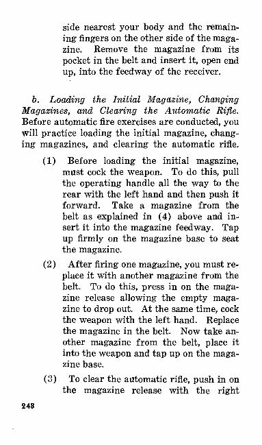
side nearest your body and the remain ing fingers on the other side of the maga zine. Remove the magazine from its pocket in the belt and insert it, open end up, into the feedway of the receiver.
b. Loading the Initial Magazine, Changing Magazines, and Clearing the Automatic Rifle. Before automatic fire exercises are conducted, you will practice loading the initial magazine, chang ing magazines, and clearing the automatic rifle.
(1) Before loading the initial magazine, must cock the weapon. To do this, pull the operating handle all the way to the rear with the left hand and then push it forward. Take a magazine from the belt as explained in (4) above and in sert it into the magazine feedway. Tap up firmly on the magazine base to seat the magazine.
(2) After firing one magazine, you must re place it with another magazine from the belt. To do this, press in on the maga zine release allowing the empty maga zine to drop out. At the same time, cock the weapon with the left hand. Replace the magazine in the belt. Now take an other magazine from the belt, place it into the weapon and tap up on the maga zine base.
(3) To clear the automatic rifle, push in on the magazine release with the right
248
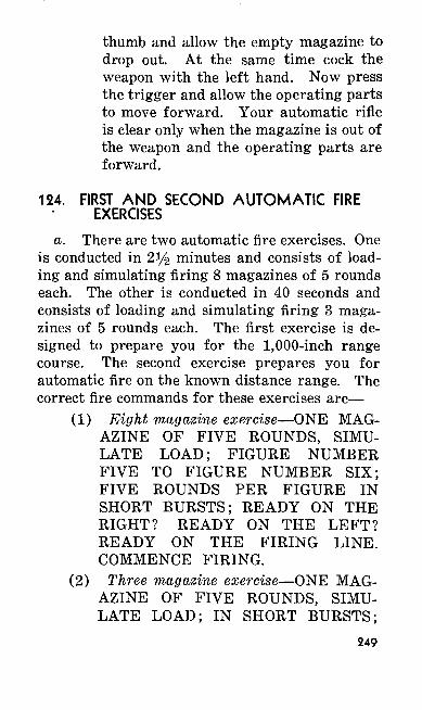
thumb and allow the empty magazine to drop out. At the same time cock the weapon with the left hand. Now press the trigger and allow the operating parts to move forward. Your automatic rifle is clear only when the magazine is out of the weapon and the operating parts are forward.
124. FIRST AND SECOND AUTOMATIC FIRE EXERCISES
a. There are two automatic fire exercises. One is conducted in 2y% minutes and consists of load ing and simulating firing 8 magazines of 5 rounds each. The other is conducted in 40 seconds and consists of loading and simulating firing 3 maga zines of 5 rounds each. The first exercise is de signed to prepare you for the 1,000-inch range course. The second exercise prepares you for automatic fire on the known distance range. The correct fire commands for these exercises are—
(1) Eight magazine exercise—ONE MAG AZINE OF FIVE ROUNDS, SIMU LATE LOAD; FIGURE NUMBER FIVE TO FIGURE NUMBER SIX; FIVE ROUNDS PER FIGURE IN SHORT BURSTS; READY ON THE RIGHT? READY ON THE LEFT? READY ON THE FIRING LINE. COMMENCE FIRING.
(2) Three magazine exercise—ONE MAG AZINE OF FIVE ROUNDS, SIMU LATE LOAD; IN SHORT BURSTS;
249
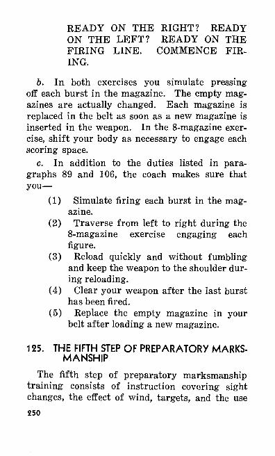
READY ON THE RIGHT? READY ON THE LEFT? READY ON THE FIRING LINE. COMMENCE FIR ING.
6. In both exercises you simulate pressing off each burst in the magazine. The empty mag azines are actually changed. Each magazine is replaced in the belt as soon as a new magazine is inserted in the weapon. In the 8-magazine exer cise, shift your body as necessary to engage each scoring space.
c. In addition to the duties listed in para graphs 89 and 106, the coach makes sure that you—
(1) Simulate firing each burst in the mag azine.
(2) Traverse from left to right during the 8-magazine exercise engaging each figure.
(3) Reload quickly and without fumbling and keep the weapon to the shoulder dur ing reloading.
(4) Clear your weapon after the last burst has been fired.
(5) Replace the empty magazine in your belt after loading a new magazine.
125. THE FIFTH STEP OF PREPARATORY MARKS MANSHIP
The fifth step of preparatory marksmanship training consists of instruction covering sight changes, the effect of wind, targets, and the use250
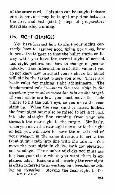
of the score card. This step can be taught indoors or outdoors and may be taught any time between the first and last (sixth) steps of preparatory marksmanship training.
126. SIGHT CHANGESYou have learned how to aline your sights cor
rectly, how to assume good firing positions, how to press the trigger so that the bullet starts on its way while you have the correct sight alinement and sight picture, and how to change magazines quickly. This information is of little value if you do not know how to adjust your sight so the bullet will strike the target where you aim. There are basic rules for making sight adjustments. The fundamental rule is—move the rear sight in the direction you want to move the hits on the target. If your shots are low, you must move the shots higher to hit the bull's eye, so you move the rear sight up. When the rear sight is raised higher, the front sight must also be raised to bring it back into the straight line running from your eye through the rear sight to the target. Similarly, when you move the rear sight down, or to the right or left, you will have to move the muzzle end of your weapon in the same direction to bring the front sight again into line with the target. You move the rear sight in clicks, both for elevation and windage. The number of clicks you must use to place your shots where you want them is ex plained later. Raising and lowering the rear sight is often referred to as putting on elevation or tak ing off elevation. Moving the rear sight to the
947041°—51—17251
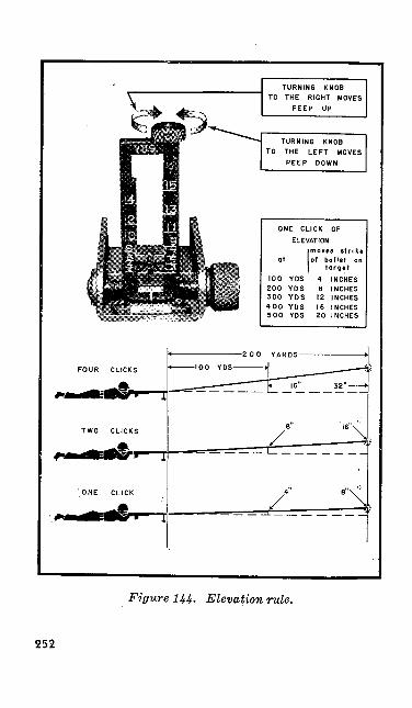
TURNING KNOBTO THE RIGHT MOVES
PEEP UP
TURNING KNOBTO THE LEFT MOVES
PEEP DOWN
ONE CLICK OF
ELEVATION
at
100200300400500
YDSYDSYDSYDSYDS
moves strikeof b ullet on
target
48
121620
INCHESINCHESINCHESINCHESINCHES
FOJR CLICKS
TWO CLICKS
'ONE CLICK
200 YARDS-
Figure 144. Elevation rule.
252
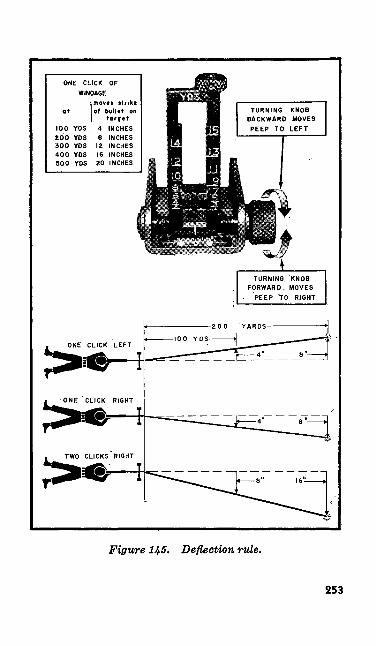
ot
ONE CLICK OF WINDAGE
(moves strikeof bullet on
target4 INCHES 6 INCHES 12 INCHES 16 INCHES 20 INCHES
100 YDS ZOO YDS 300 YDS 400 YDS 500 YDS
ONE CLICK LEFT
ONE "CLICK RIGHT
TWO CLICKS RIGHT
Figure 145. Deflection rule.
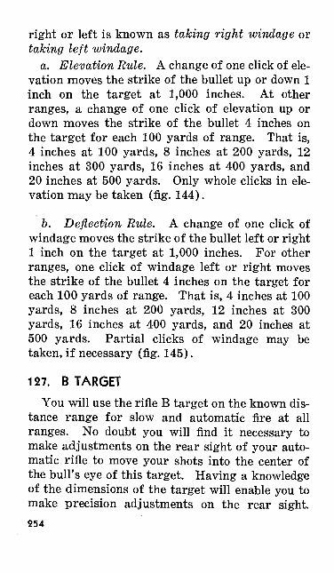
right or left is known as taking right windage or taking left windage.
a. Elevation Rule. A change of one click of ele vation moves the strike of the bullet up or down 1 inch on the target at 1,000 inches. At other ranges, a change of one click of elevation up or down moves the strike of the bullet 4 inches on the target for each 100 yards of range. That is, 4 inches at 100 yards, 8 inches at 200 yards, 12 inches at 300 yards, 16 inches at 400 yards, and 20 inches at 500 yards. Only whole clicks in ele vation may be taken (fig. 144).
6. Deflection Rule. A change of one click of windage moves the strike of the bullet left or right 1 inch on the target at 1,000 inches. For other ranges, one click of windage left or right moves the strike of the bullet 4 inches on the target for each 100 yards of range. That is, 4 inches at 100 yards, 8 inches at 200 yards, 12 inches at 300 yards, 16 inches at 400 yards, and 20 inches at 500 yards. Partial clicks of windage may be taken, if necessary (fig. 145).
127. B TARGETYou will use the rifle B target on the known dis
tance range for slow and automatic fire at all ranges. No doubt you will find it necessary to make adjustments on the rear sight of your auto matic rifle to move your shots into the center of the bull's eye of this target. Having a knowledge of the dimensions of the target will enable you to make precision adjustments on the rear sight.254
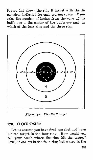
Figure 146 shows the rifle B target with the di mensions indicated for each scoring space. Mem orize the number of inches from the edge of the bull's eye to the center of the bull's eye and the width of the four ring and the three ring.
Figure 146. The rifle B target.
128. CLOCK SYSTEMLet us assume you have fired one shot and have
hit the target in the four ring. How would you tell your coach where the shot hit the target? True, it did hit in the four ring but where in the
255
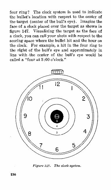
four ring? The clock system is used to indicate the bullet's location with respect to the center of the target (center of the bull's eye). Imagine the face of a clock placed over the target as shown in figure 147. Visualizing the target as the face of a clock, you can call your shots with respect to the scoring space where the bullet hit and the hour on the clock. For example, a hit in the four ring to the right of the bull's eye and approximately in line with the center of the bull's eye would be called a "four at 3:00 o'clock."
Figure H7. The clock system.
256
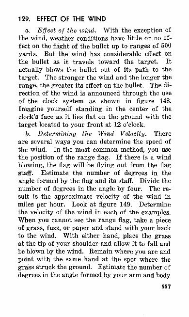
129. EFFECT OF THE WINDa. Effect of the wind. With the exception of
the wind, weather conditions have little or no ef fect on the flight of the bullet up to ranges of 500 yards. But the wind has considerable effect on the bullet as it travels toward the target. It actually blows the bullet out of its path to the target. The stronger the wind and the longer the range, the greater its effect on the bullet. The di rection of the wind is announced through the use of the clock system as shown in figure 148. Imagine yourself standing in the center of the clock's face as it lies flat on the ground with the target located to your front at 12 o'clock.
b. Determining the Wind Velocity. There are several ways you can determine the speed of the wind. In the most common method, you use the position of the range flag. If there is a wind blowing, the flag will be flying out from the flag staff. Estimate the number of degrees in the angle formed by the flag and its staff. Divide the number of degrees in the angle by four. The re sult is the approximate velocity of the wind in miles per hour. Look at figure 149. Determine the velocity of the wind in each of the examples. When you cannot see the range flag, take a piece of grass, fuzz, or paper and stand with your back to the wind. With either hand, place the grass at the tip of your shoulder and allow it to fall and be blown by the wind. Remain where you are and point with the same hand at the spot where the grass struck the ground. Estimate the number of degrees in the angle formed by your arm and body
257
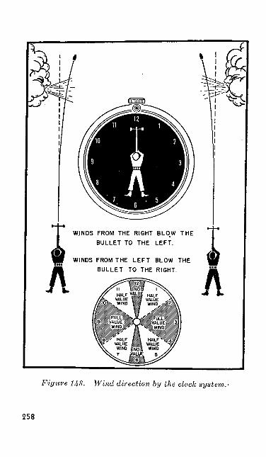
rinnin
WINDS FROM THE RIGHT BLOW THE BULLET TO THE LEFT.
WINDS FROM THE LEFT BLOW THE BULLET TO THE RIGHT.
Figure 148. Wind direction by the clock system.
258
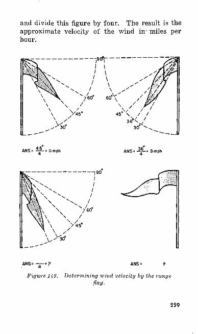
and divide this figure by four. The result is the approximate velocity of the wind in' miles per hour.
ANS = ~-= llmph ANS = --= 9mph
ANS =
Figure H9. Determining wind velocity by the range flag.
259
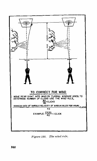
TO CORRECT FOR WINDMOVE REAR SIGHT INTO WIND BY TURNING WINDAGE KNOB. TO DETERMINE NUMBER OF CLICKS USE THE WIND RULE,
^.CLICKS
RANGE1IN IQO'l OF YARDS) X VELOCITY OF WINDJIN MILES PER HOUR)
40^CLICKS
EXAMPLE: 1 CLICK
Figure 150. The wind rule.
260
c. Wind rule. The effect that a wind has on the bullet varies with the velocity of the wind, the distance the bullet travels, and the direction in which the wind is blowing. A wind blowing di rectly from 12 or 6 o'clock does not noticeably affect the flight of the bullet and no sight adjust ment is necessary. You must compensate for winds blowing from other directions. Winds from 2, 3, or 4 and 8, 9, or 10 o'clock are called full- value winds because they have the most effect upon the bullet. Winds blowing from 1, 5, 7, and 11 o'clock have only about half as much effect on the bullet and are called half-value winds. To compensate for a wind, the rear sight must be moved to the left or right. Move the sight as .shown in figure 150. Here is a step by step ex planation of the formula:
(1) Take the range at which you are firing (200, 300, or 500 yards) and express it in hundreds of yards (2, 3 or 5).
(2) Determine the velocity of the wind in miles per hour.
(3) Multiply the above two elements and divide the results by the constant num ber 40.
(4) The result is the number of clicks of windage for a full value wind.
(5) Here is a typical problem and its solu tion:
(a) Assume that you are firing at 200 yards. A 20 mile per hour wind is blowing from 3 o'clock. How much
261
do you correct for the wind? (As the wind is blowing from 3 o'clock, it is a full value wind.)
(b) Range expressed in hundreds of yards = 2.
(c) Velocity of the wind in miles per hour = 20.
(d) RxV = 2x20 == 40 = 1 click 40 40 40
(e) The correction for the wind is 1 click right windage—into the wind. (If the were blowing from 1 or 5 o'clock, a half-value wind, you would move the rear sight just half as many clicks or 1/2 click.)
130. ZEROING THE AUTOMATIC RIFLEa. General. Each automatic rifle has certain
individual characteristics like shooting a little low or high and perhaps to the left or right at different ranges. You must make sight changes to correct for these characteristics of your weapon. Adjusting the rear sight to allow for these characteristics is known as zeroing your automatic rifle. To zero your automatic rifle you must make elevation and windage corrections until your weapon shoots where it is aimed. The zero that you obtain with these corrections usually differs from the manufacturer's zero. The zero of your automatic rifle, for each range, is the sight setting in elevation and loindage that enables you to hit the center of the bull's eye on a normal day when no wind is bluing.262
b. To Zero the Automatic rifle. There are two ways to zero your automatic rifle.
(1) The first way is by firing three groups of three rounds each. For a detailed discussion of this procedure, see para graph 150.
(2) A second way to zero the automatic rifle is to fire a single shot. Have the target marked (when firing the 1,000- inch course the shot can be seen from the firing line). Make the necessary sight change to move the next shot into the center of the bull's eye. Fire another round. Continue this until the shots are hitting in the center of the bull's eye. The final setting that you have on the rear sight is the zero of your automatic rifle for that range. Record this zero on your score card. After you are able to call your shots correctly, use the sec ond method for zeroing. For men who are learning to shoot, the first method is better.
131. SCORE CARDa. To help you learn something from each shot
and to help you determine the automatic rifle's zero for each range, you are given a score card. The proper use of the score card enables you to zero your automatic rifle quickly and accurately. It serves not only as a record of the score you shoot but also tells the complete story of every shot you fire. A study of the entries you make
263
on the score card enable you or your officers or noncommissioned officers to analyze your shooting to determine what you did wrong for each shot that was not a good one. Learning what is wrong is the first step toward corrective action.
b. To obtain the maximum use of your score card, you and only you must make the entries. Make these entries immediately after you fire each shot. Do not let your coach or anyone else plot your call or shot for you because he will not know what your sight picture really looked like at the time the weapon fired. Do not fool yourself by calling each shot a center bull's eye. Concentrate on your sight picture, hold your breath, press the trigger smoothly, and follow through and you will be able to call your shots correctly. The best marksmen in the world call every shot and they call very few of them center bull's eyes. Another important thing is to plot your shots accurately on the miniature target on the score card. Study the spotters on your target and plot each shot in its exact location. You will only hurt yourself if you plot a wide 3 as one that is almost a 4. And if it is a 7 o'clock shot on the target do not plot it at 6 o'clock just to make your score card look better.
c. Each time you go to the range you are given time in which to fill out the headings of your score card. Print your name, grade, army service num ber, organization, date and place of firing, the course that you are to fire, and indicate whether you are firing instruction or record practice. Check the weather conditions, particularly the264
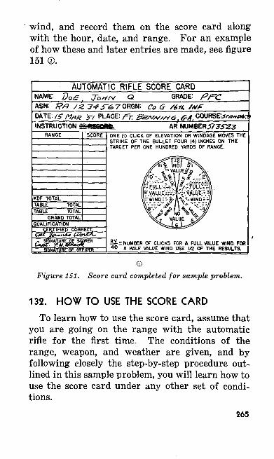
wind, and record them on the score card along with the hour, date, and range. For an example of how these and later entries are made, see figure 151®.
AUTOMATIC RIFLE SCORE CARDNAME: Q GRADE:ASM: Co GDATE: 15 nftK 'r, PLACE: f=r. s &A.INSTRUCTION AR HIMBE.KS77SZ3
RANGE
KDF TOTAL
GRAND TOTALQUALIFICATION
TIFIED
ATUBE OF OFFICER
ONE (I) CLICK OF ELEVATION OR WINDAGE MOVES THE STRIKE OF THE BULLET FOUR (4) INCHES ON THE TARGET PER ONE HUNDRED YARDS OF RANGE.
B. = NUMBER OF CLICKS FOR A FULL VALUE WIND. FOR 40 A HALF VALUE WIND USE 1/2 OF THE RESULTS,
Figure 151. Score card completed for sample problem.
132. HOW TO USE THE SCORE CARDTo learn how to use the score card, assume that
you are going on the range with the automatic rifle for the first time. The conditions of the range, weapon, and weather are given, and by following closely the step-by-step procedure out lined in this sample problem, you will learn how to use the score card under any other set of condi tions.
265
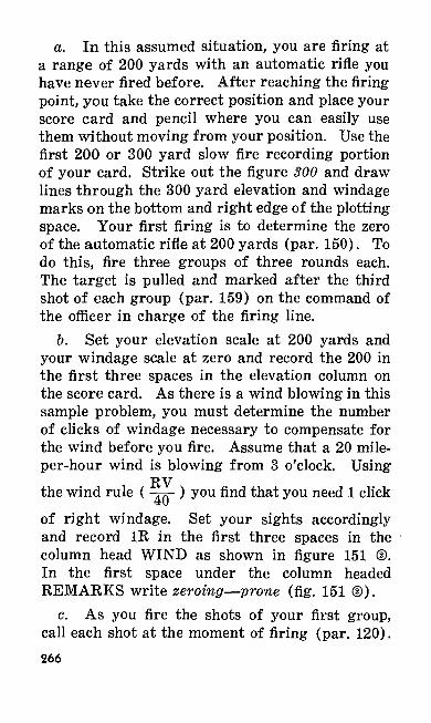
a. In this assumed situation, you are firing at a range of 200 yards with an automatic rifle you have never fired before. After reaching the firing point, you take the correct position and place your score card and pencil where you can easily use them without moving from your position. Use the first 200 or 300 yard slow fire recording portion of your card. Strike out the figure 300 and draw lines through the 300 yard elevation and windage marks on the bottom and right edge of the plotting space. Your first firing is to determine the zero of the automatic rifle at 200 yards (par. 150). To do this, fire three groups of three rounds each. The target is pulled and marked after the third shot of each group (par. 159) on the command of the officer in charge of the firing line.
b. Set your elevation scale at 200 yards and your windage scale at zero and record the 200 in the first three spaces in the elevation column on the score card. As there is a wind blowing in this sample problem, you must determine the number of clicks of windage necessary to compensate for the wind before you fire. Assume that a 20 mile- per-hour wind is blowing from 3 o'clock. Using
RVthe wind rule ( -^- ) you find that you need 1 clickof right windage. Set your sights accordingly and record 1R in the first three spaces in the column head WIND as shown in figure 151 ®. In the first space under the column headed REMARKS write zeroing—prone (fig. 151 ©).
c. As you fire the shots of your first group, call each shot at the moment of firing (par. 120).266
The call is the sight picture you saw as your weapon fired, not what you intended to fire. Re cord each call by placing a dot in the square with the circle representing the bull's eye in the CALL column. After the third shot, clear your auto matic rifle and wait for the target to be marked. Look at your target and notice the exact location of the three spotters. Plot these shots on the re cording target of your score card in the exact location as they appear on the target (fig. 151 ©).
©Figure 151—Continued.
d. Examine your shot group and determine how far you must move the center of the shot group for it to be in the center of the bull's eye. By using the dimensions of the target (par. 163) or the elevation and windage lines on the score card, determine how many clicks of elevation and windage you need. In this assumed situation, you determine that you need 2 more clicks of eleva tion, and 21/2 more clicks of right windage making
947041°—51—18267
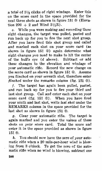
a total of 31/2 clicks of right windage. Enter this on the score card in the space provided for the next three shots as shown in figure 151 ® (Eleva tion 200 + 2 and Wind 3i/2 R)-
e. While you were making and recording these sight changes, the target was pulled, pasted and run back up for you to fire the next shot group. After you have fired this shot group and called and marked each shot on your score card (as shown in figure 151 ©) again determine what sight changes you need to make to hit the center of the bull's eye (d above). Subtract or add these changes to the elevation and windage of your automatic rifle. Record the new change on the score card as shown in figure 151 ©. Assume you flinched on your seventh shot, therefore enter flinched under the remarks column (fig. 151 ©).
/. The target has again been pulled, pasted, and run back up for you to fire your third and last shot group. Call and enter each shot on your score card (fig. 151 ©). When you have fired your ninth and last shot, write last shot under the REMARKS column in the space provided for the last shot as shown in figure 151 ©.
g. Clear your automatic rifle. The target is again marked and you enter the values of these shots on your score card. Total the score and enter it in the space provided as shown in figure 151®.
h. You should now have the zero of your auto matic rifle when a 20 mile-per-hour wind is blow ing from 3 o'clock. To get the zero of the auto matic rifle when no wind is blowing, subtract one268
click of right windage from 2^/^R, which is the total windage you now have. One click of right windage was the change that you made when you determined the velocity and direction of the wind (par. 129). What you have left, li/2R. is the zero windage of your automatic rifle. The zero eleva tion of your weapon for 200 yards is 200 yards + 1. Record the zero windage and zero elevation as shown in figure 151 ©.
i. Record information for other known dis tance firing and for 1,000-inch firing in the same way as described for 200 yards. The only excep tion is that the effect of a change in elevation or windage varies for different ranges (par. 126).
133. EXAMINATIONa. General. You will be tested when you com
plete the five steps of preparatory marksmanship training. This test will indicate how much you have learned. If you do not pass this preparatory marksmanship test, you should not proceed to the range for firing until you receive additional in struction in those steps of training in which the examination shows you are weak. The examina tion is given well before range firing to allow for additional instruction if needed and includes ques tions on each of the first five steps. Some ques tions may be answered in a few simple words. For other questions, a demonstrator may perform an exercise and you will be required to critique certain parts of his performance. For still other questions you may be told to demonstrate a posi-
269
tion or perhaps some of the exercises that you learned in preparatory marksmanship training.
b. Sample Questions. The following list of questions covers the instruction presented in training. You should be able to answer all of these questions.
Q. What is the name of your weapon?A. The Browning automatic rifle, caliber .30,
M1918A2.Q. What type weapon is it ?A. A shoulder weapon, gas operated, air
cooled, magazine fed, fully automatic, and equipped with an adjustable bipod.
Q. How is the barrel cooled ?A. The barrel is cooled by being exposed to
the air. There is no special cooling device.Q. What is meant by "gas operated"?A. All the functions of the automatic rifle,
such as extraction and ejection, are accomplished by a small portion of the gas escaping through a gas port in the barrel. The powder gases strike the piston which forces the parts to the rear caus ing the weapon to function.
Q. What is the maximum number of rounds the magazine will hold ?
A. Twenty.Q. What care must be taken of the magazines ?A. They must be kept clean and oiled. To pre
vent oil getting on the ammunition, only a very light film of oil should be kept.on the inside of the magazine. The magazines must not be damaged in any way.
Q. How are the magazines filled?270
A. By using the magazine filler or by hand. Normally they are loaded by hand.
Q. Why should the spare parts kit be carried complete at all times?
A. Because it contains equipment which is necessary to keep the automatic rifle in action.
Q. What is the first thing to do in case of a stoppage?
A. Apply the first phase of immediate action.Q. What is the next thing to do in case you
have tried to fire again and the automatic rifle still fails to fire.
A. Apply the second phase of immediate action.
Q. What are the two main causes of the auto matic rifle firing a single shot after the first phase of immediate action has been applied?
A. Insufficient gas and magazine trouble.Q. What usually causes a failure to feed?A. Magazine trouble.Q. How can you tell when the automatic rifle
is receiving insufficient gas?A. The automatic rifle will fire but the bolt
will not go all the way to the rear. Usually the empty cartridge case is not ejected and is wedged in the ejection opening as the operating parts move forward.
Q. What is meant by sight alinement?A. The proper positioning of the front sight
post in relation to the peep or notch of the rear sight.
Q. Explain correct sight alinement.271
A. You have correct sight alinement when the top of the front sight blade touches an imaginary horizontal line through the center of the peep sight and when an imaginary vertical line through the center of the peep sight divides the front sight in half.
Q. How do you obtain the correct sight pic ture?
A. Add the bull's eye to the correct sight aline ment so that the bottom of the bull's eye just touches the center of the top of the front sight.
Q. What is the purpose of the sighting and aiming bar ?
A. To teach the automatic rifleman how to aim.
Q. Why is the sighting and aiming bar better than an automatic rifle for this purpose?
A. Because the sights on it are much larger and slight errors can be easily seen and pointed out.
Q. What is the purpose of the eyepiece ?A. To cause the automatic rifleman to place
his eye in such a position that he will see the sights in the same way that the coach sees them.
Q. Where is the last focus of the eye when aiming the automatic rifle?
A. On the front sight.Q. Demonstrate the proper sight picture by
using the sighting bar.A. (The man being examined adjusts the mov
able rear sight and bull's eye so that the sights are correctly alined on the target and then hands it to the instructor to be checked.272
Q. How do you hold the breath while aiming and firing?
A. Take in an ordinary breath, let out a little; and then, by closing the throat, hold the remainder while aiming and pressing the trigger.
Q. What is the best position from which to fire the automatic rifle ?
A. The prone position, using the hinged butt plate and the bipod.
Q. Why is the sling used with the automatic rifle in the sitting and kneeling positions?
A. To assist the automatic rifleman in hold ing the rifle steady.
Q. How do you press the trigger in firing bursts at the slow cyclic rate?
A. Press the trigger rapidly but uniformly all the way to the rear. Hold the trigger to the rear for the desired length of burst.
Q. In firing, what care must be taken with reference to your sight alinement?
A. You must be careful to keep your sights alined correctly on the target from the time you start to press the trigger until the cartridge is fired, being particularly careful to do this while the bolt is going forward.
Q. How do you insure that each shot, after the first shot of the burst, hits the target?
A. To insure that succeeding shots of the burst will hit the target, take correct position and hold the rifle steady throughout the burst.
Q. Is it necessary to take a long time in press ing the trigger ?
273
A. No; necessary speed is developed by prac tice in trigger manipulation.
Q. How do you press the trigger in firing single shots?
A. Press it quickly but uniformly all the way to the rear and then release it immediately.
Q. In firing several bursts, how do you gain time so as not to be compelled to hurry in aiming?
A. By changing magazines rapidly and by keeping your eye on the target while firing.
Q. How does keeping your eye on the target help you to gain time?
A. A man who looks away loses time in find ing his target again.
Q. Is it important to always get into the cor rect position before beginning to shoot?
A. Yes; even though it takes more time, you should always get into the correct position before beginning to shoot. Your shots will be more ac curate if your position is correct.
Q. What is meant by calling the shot?A. The automatic rifleman announces where
he thinks the bullets hit when firing single shots and where the first round hit when firing bursts.
Q. How can you do this?A. By concentrating your attention on the
sight alinement and sight picture as you press the trigger.
Q. What effect does moving the rear sight have on the shot?
A. It moves the shot in the same direction that the rear sight has been moved.
274
Q. If you want to make a shot hit higher, what do you do ?
A. Increase (raise) the setting on the rear sight.
Q. If you want to make your shots hit to the right, what do you do?
A. Move the rear sight to the right.Q. If you move your rear sight one click of
windage, how much will it move the strike of the bullet?
A. Four inches for each 100 yards of range.Q. What are the three principal uses of the
score card ?A. To keep an accurate record of where each
of the shots hit the target, to indicate how much change in the sight is necessary to move a shot or group of shots to the center of the target, and to make a record of the sight settings of the auto matic rifle for the different ranges under various conditions so that you will know the zero of your automatic rifle.
Q. In firing at ranges up to and including 500 yards, what is the only weather condition for which you make sight corrections?
A. Wind.Q. What four things do you do in cleaning an
automatic rifle bore after it has been fired ?A. First, remove the powder fouling from the
bore. Second, dry the bore thoroughly of the liquid used to remove the fouling. Third, inspect the bore, repeating the cleaning if necessary. Fourth, oil the bore.
275
Q. How do you remove powder fouling from the bore?
A. By swabbing it thoroughly with patches saturated with bore cleaner. In the absence of bore cleaner, use warm soapy water.
Q. How do you dry the bore?A. By running clean patches through the bore
until one conies out dry.Q. How do you protect the bore from rust?A. By swabbing it thoroughly with a cleaning
patch dampened with oil.Q. How should the metal parts of the auto
matic rifle be oiled ?A. By using an oily cloth to place a thin film
of oil over all metal parts.In addition to answering questions similar to
those already given, you may be required to dem onstrate your ability to assume the correct firing positions, change magazine, manipulate the trig ger, and to make sight changes.
c. Scoring Sheet. A scoring sheet like the one shown below can be used as a guide in examining and grading practical work questions. Notice that a space is provided for a reexamination.
276

Subj
ect
1 M
echa
nica
l tra
inin
g
2 Fu
nctio
ning
3 Ca
re a
nd c
leani
ng
4 Si
ghtin
g ba
r
5 Sh
ot g
roup
exe
rcise
s
6 Lo
op a
nd h
asty
slin
g
7 Po
sitio
ns
8 Tr
igger
man
ipul
ation
9 Lo
adin
g m
agaz
ine
in be
lt
Exam
inat
ion
Satis
fact
ory
Uns
atis
fact
ory
Ree
xam
inat
ion
Satis
fact
ory
Uns
atis
fact
ory
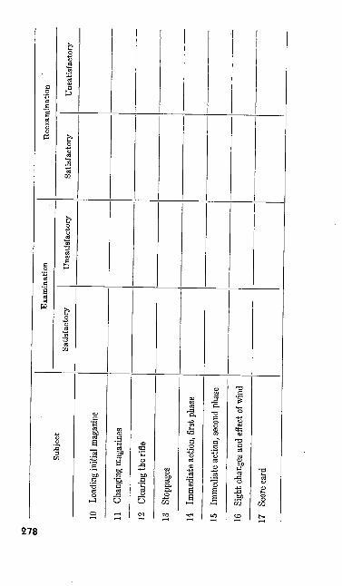
to
-J 00
Subj
ect
10
Load
ing
initi
al m
agaz
ine
11
Chan
ging m
agaz
ines
12
Clea
ring
the
rifle
13
Stop
page
s
14
Imm
edia
te a
ction
, firs
t pha
se
15
Imm
ediat
e ac
tion,
seco
nd p
hase
16
Sigh
t cha
nges
and
effe
ct of
wind
17
Scor
e card
Exam
inat
ion
Satis
fact
ory
Uns
atis
fact
ory
Ree
xam
inat
ion
Satis
fact
ory
Uns
atisf
acto
ry
Section III. COURSES AND SCORE CARDS
134. GENERALa. Current regulations authorize each officer,
warrant officer, and enlisted man in the army to fire a qualification course with his basic weapon and a familiarization course with other weapons. There are five automatic rifle qualification courses —a standard course and four shorter courses. The different courses are set up so that the special marksmanship training needs of men in all kinds and types of units can be taken care of.
6. Each complete course is made up of a series of numbered tables-that you fire in order. Each table is a concise statement of conditions (range, rate of fire, time allowance, and targets) under which you fire a prescribed number of the rounds authorized for the course.
c. The amount of instruction firing is not lim ited to that prescribed in the tables. Additional practice may be given when time and ammunition allowances permit. No automatic rifleman is per mitted to fire automatic fire until he has demon strated proficiency in slow fire.
d. Although the 1,000-inch range does not ap pear in the tables for the A, B, and C courses, it can be used to advantage during instruction firing. When time or men for target operation is limited, the 1,000-inch range should be used for the initial phase of instruction practice. At this range, you become accustomed to the noise and recoil of the automatic rifle as you perfect your positions, trigger manipulation, aiming, and ability to change magazines quickly. Having zeroed your
279
automatic rifle at 1,000-inches, you can use this zero as a basis for zeroing your automatic rifle at the longer ranges. You can learn all basic elements of marksmanship by firing on the 1,000- inch range. Pit details and telephone operators are not needed, as each hit is visible to the firer. The 1,000-inch target (par. 163) is used for all firing conducted on the 1,000-inch range. The rifle B target (par. 163) is used for all known distance range firing.
e. In all courses where single shots are to be fired for zeroing purposes, the cartridges are loaded into the weapon one at a time. In all other cases where single shots are to be fired, the specified number of cartridges is loaded into the magazine and you attempt to fire single shots.
135. STANDARD COURSEa. General. The standard course consists of
eight tables. It is designed to teach you the funda mentals of precision firing with the automatic rifle and the use of the battle sight setting (zero on your automatic rifle at 300 yards) in firing at field targets at various, unannounced ranges. When you complete the standard course you are qualified to advance to the team phase of auto matic rifle training. The standard course includes known distance firing and transition firing. This course is designed to more adequately prepare you for combat type firing.
b. Known Distance Firing. The known dis tance portion of the standard course consists of five tables. These tables are designed to teach you how to fire your automatic rifle accurately280
from known distances at a target. All principles of automatic rifle marksmanship as taught during preparatory marksmanship training are applied during this firing. Instruction practice consists of firing tables I, II, and III at least once. Record firing consists of firing tables IV and V only once.
c. Transition Firing. The transition firing part of the course includes firing at field targets from combat type positions (from roof tops and through windows) as well as firing from the crouch position at surprise targets from short ranges. It is preceded by preliminary marksman ship training in the theory and use of the battle sight at ranges up to 400 yards. Instruction is also given in the use of the aiming point and in range estimation. While firing table VI, you be come familiar with the appearance of targets and the distance to them at various ranges. Before you fire table VII, you receive instruction in firing from combat positions without using the sling (FM 23-5), and you are not permitted to fire tables VII and VIII until after you have demon strated your ability in firing table VI. Instruc-
'tion firing consists of firing tables VI, VII, and VIII at least once. Record practice consists of fir ing tables VII and VIII only once.
d. Qualification Scores. The total of your rec ord firing scores for tables IV, V, VII and VIII determines your classification as an automatic rifleman. The minimum standard course qualify ing scores for the three classifications are:
(1) Expert automatic rifleman 350 points.(2) Automatic rifle sharpshooter 310 points.(3) Automatic rifle marksman 270 points.
281
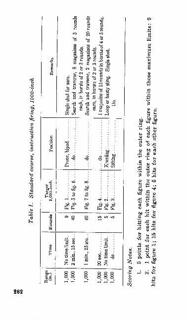
K>
00
N>
Tabl
e I.
Stan
dard
cou
rse,
inst
ruct
ion
firin
g, 1
000-
inch
Ran
ge
(in.)
1,00
01,
000
1,00
0
1,00
01,
000
1,00
0
Tim
e
20 se
c do...
......
Rou
nds
40 40 15 5 5
Targ
et
1,00
0-in
ch
Fig.
1..
....
....
..Fi
g. 5
to fi
g. 6.
...
Fig.
7 to
fig.
8. .
. .
Fig.
4. ...........
Fig.
2............
Fig.
3. ...........
Posi
tion
....do................
....do................
....do................
Rem
arks
each
, in
burs
ts of
2 or
3 ro
unds
.
each
, in
burs
ts of
2 or
3 ro
unds
.
Do.
Scor
ing
Not
es.
1.
5 po
ints
for
hitt
ing
each
fig
ure
with
in t
he o
uter
rin
g.2.
1
poin
t fo
r ea
ch h
it w
ithin
the
out
er r
ing
of e
ach
figur
e w
ithin
the
se m
axim
um l
imits
: 9
hits
for
fig
ure
1; 1
5 hi
ts f
or f
igur
e 4;
5 h
its f
or e
ach
othe
r fig
ure.
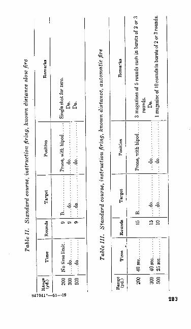
Tabl
e II
. St
anda
rd c
ours
e, i
nstr
uctio
n fir
ing,
kno
wn
dist
ance
slo
w fi
re
O £ R
ange
l«
(yd.
)V
I J-
onn
300
500
Tim
e
....d
o.........
....d
o.........
Rou
nds 9 9 9
Tar
get
B. .
..... .........
....d
o............
....d
o............
Posit
ion
....d
o................
....d
o..
.............
Rem
arks
Do.
Do.
Tabl
e II
I.
Stan
dard
cou
rse,
inst
ruct
ion
firin
g, k
now
n di
stan
ce,
auto
mat
ic fi
re
Ran
ge(yd
.) 200
300
500
Tim
e
40 s
ec...
......
40 se
c. ........
25 se
c. ..
....
..
Rou
nds 15 15 10
Targ
et
B. .
..............
....do............
....do............
Posi
tion
....do................
....d
o. ...
....
....
....
Rem
arks
roun
ds.
Do.
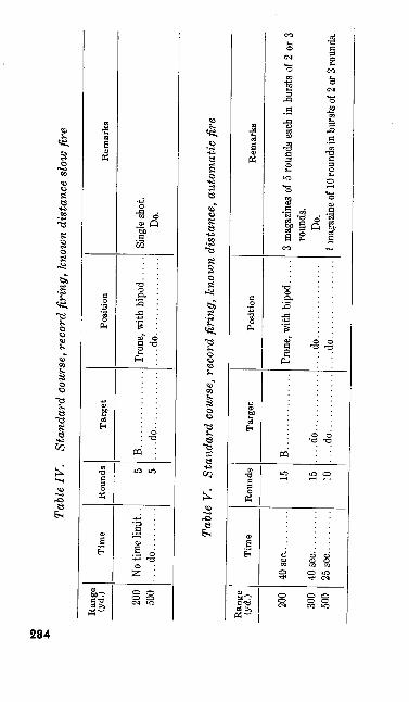
to 00
Tabl
e IV
. St
anda
rd c
ours
e, r
ecor
d fir
ing,
kno
wn
dist
ance
slo
w fir
e
Ran
ge(y
d.) 200
500
Tim
e
....d
o....
.....
Rou
nds 5 5
Targ
et
B................
....do............
Posi
tion
....do................
Rem
arks
Do.
Tabl
e V.
St
anda
rd c
ours
e, r
ecor
d fir
ing,
kno
wn
dist
ance
, aut
omat
ic fi
re
Ran
ge(y
d.) 200
300
500
Tim
e
40 s
ec. .
.......
25 s
ec. .
.......
Rou
nds 15 15 10
Targ
et
B....... .........
....do............
....do............
Posi
tion
....do................
....do................
Rem
arks
roun
ds.
Do.
1 mag
azin
e of 1
0 rou
nds i
n bu
rsts
of 2 o
r 3 ro
unds
.
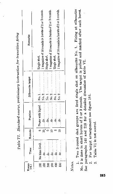
Tabl
e V
I.
Stan
dard
cou
rse,
pre
limin
ary
inst
ruct
ion
for
tran
sitio
n fir
ing
Ran
ge(y
d.) 300
onn
200
200
400
400
Tim
e
No ti
me l
imit.
. ....do.........
....do.........
....do.........
....do.........
....d
o....
.....
Rou
nds 6 10 e" 10 6 10
Posi
tion
Pron
e wi
th b
ipod
. . ....do............
....do............
....do............
....do............
....do............
Silh
ouet
te t
arge
t
No. 1
................
No. 2
................
No. 1
................
NO; :i
.. ...
......
.....
No. 1
................
No. 2
................
Rem
arks
Sing
le sh
ot.
1 mag
azine
of 10
roun
ds in
burst
s of 2
or 3
roun
ds.
Not
es. 1.
Two
3-ro
und
shot
gro
ups
are
fired
sin
gle
shot
on
silh
ouet
te N
o. 1
. Fi
ring
at
silh
ouet
te
No.
2 i
s do
ne i
n sh
ort
burs
ts o
f 2
or 3
rou
nds.
T
he t
arge
t is
pul
led
and
mar
ked
afte
r ea
ch b
urst
.
See
para
grap
hs 1
40 a
nd 2
18 f
or a
det
aile
d di
scus
sion
of
tabl
e V
I.
2. Fo
r ta
rget
arr
ange
men
t se
e fig
ure
164.
3. Ta
ble
VI
is n
ot s
core
d.K
> 00 in
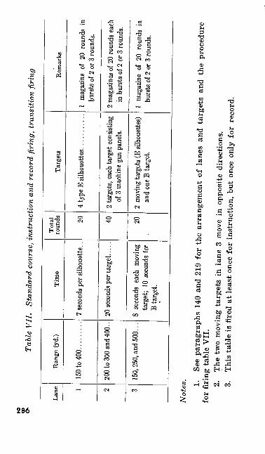
$Ta
ble
VII
. St
anda
rd c
ours
e, in
stru
ctio
n an
d re
cord
firi
ng,
tran
sitio
n fir
ing
Lane 1 2 3
Ran
ge (
yd.)
150
to 4
00. .
.......
200 t
o 300
and 4
00..
150,
250,
and
500.
..
Tim
e
20 se
cond
s per
targe
t. ....
8 se
cond
s ea
ch m
oving
tar
get;
10 s
econ
ds fo
r B
targe
t.
Tota
l ro
unds 20 40 20
Targ
ets
2 tar
gets,
eac
h ta
rget
cons
isting
of
3 mac
hine
gun
pane
ls.
2 mo
ving t
arge
ts (E
silho
uette
s) an
d on
e B ta
rget.
Rem
arks
burs
ts of
2 or
3 ro
unds
.
2 ma
gazin
es o
f 20
roun
ds e
ach
in bu
rsts o
f 2 o
r 3 ro
unds
.
1 ma
gazin
e of
20 r
ound
s in
burst
s of 2
or 3
roun
ds.
Not
es. 1.
See
para
grap
hs 1
40 a
nd 2
19 f
or t
he a
rran
gem
ent
of l
anes
and
tar
gets
and
the
pro
cedu
re
for
firi
ng ta
ble
VII
.2.
Th
e tw
o m
ovin
g ta
rget
s in
lan
e 3
mov
e in
opp
osite
dir
ectio
ns.
3.
Thi
s ta
ble
is f
ired
at le
ast
once
for
ins
truc
tion,
but
onc
e on
ly f
or r
ecor
d.
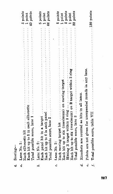
4.
Scor
ing—
a.
Lane
No.
1:
Eac
h si
lhou
ette
hit
......................................................
5 po
ints
Each
hit
up to
5 in
eac
h si
lhou
ette
..........................................
1 po
int
Tota
l po
ssib
le s
core
, lan
e 1
................................................
40 p
oint
s
b. La
ne N
o. 2
:Ea
ch p
anel
hit
in a
. tar
get
................................................
5 po
ints
Each
hit
up to
6 in
eac
h pa
nel .............................................
1 po
int
Tota
l pos
sibl
e sc
ore,
lane
2 .
...............................................
66 p
oint
s
c. La
ne N
o. 3
:Ea
ch m
ovin
g ta
rget
hit
....................................................
5 po
ints
Eac
h hi
t up
to
six
(max
imum
) on
mov
ing
targ
et ...........................
1 po
int
Hitt
ing
B ta
rget
with
in 3
rin
g .............................................
5 po
ints
Eac
h hi
t up
to s
ix (
max
imum
) on
B ta
rget
with
in 3
rin
g .....................
1 po
int
Tota
l po
ssib
le s
core
, lan
e 3
...............................................
33 p
oint
s
d.
Ric
oche
ts a
re c
ount
ed a
s hi
ts i
n al
l la
nes.
e. Po
ints
are
not
giv
en f
or u
nexp
ende
d ro
unds
in
any
lane
.
/. To
tal p
ossi
ble
scor
e, t
able
VII
..............................................
139
poin
ts
to 00
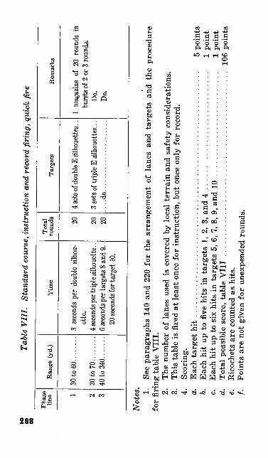
00
OBTa
ble
VII
I. St
anda
rd c
ours
e, in
stru
ctio
n an
d re
cord
firi
ng, q
uick
fire
Phas
e lin
e 1 2 3
Ran
ge (
yd.)
30 to
60.
......
.
30 to
70.
......
.40
to 3
40...
....
Tim
e
ette
.
20 se
cond
s for
targ
et 1
0.
Tota
l ro
unds 20 20 20
Targ
ets
3 sets
of t
riple
E si
lhou
ettes
. . .
....do......................
Rem
arks
1 ma
gazin
e of
20 r
ound
s in
burst
s of 2
or 3
roun
ds.
Do.
Do.
Not
es. 1.
See
para
grap
hs 1
40 a
nd 2
20 f
or t
he a
rran
gem
ent
of l
anes
and
tar
gets
and
the
pro
cedu
re
for
firi
ng ta
ble
VII
I.2.
Th
e nu
mbe
r of
lan
es u
sed
is c
over
ed b
y lo
cal
terr
ain
and
safe
ty c
onsi
dera
tions
.3.
T
his
tabl
e is
fire
d at
leas
t onc
e fo
r in
stru
ctio
n, b
ut o
nce
only
for
rec
ord.
4.
Scor
ing.
a.
Eac
h ta
rget
hit
..........................................................
5 po
ints
6. E
ach
hit
up t
o fiv
e hi
ts i
n ta
rget
s 1,
2,
3, a
nd 4
............................
1 po
int
c. E
ach
hit
up t
o si
x hi
ts i
n ta
rget
s 5,
6, 7
, 8, 9
, and
10
.........................
1 po
int
d.
Tot
al p
ossi
ble
scor
e, t
able
VII
I ............................................
106
poin
tse.
Ric
oche
ts a
re c
ount
ed a
s hi
ts.
/. Po
ints
are
not
giv
en f
or u
nexp
ende
d ro
unds
.
136. COURSE Aa. General. Course A consists of four tables
and is fired when the range facilities required for the standard course are not available. The instruc tion firing outlined in tables I and II is advisory only.
b. Qualification Scores. The total of your table III and table IV record scores determines your classification as an automatic rifleman. The minimum course A qualifying scores for the three classifications are:
(1) Expert automatic rifleman 200 points(2) Automatic rifle sharp
shooter ............... 175 points(3) Automatic rifle marksman 140 points
289
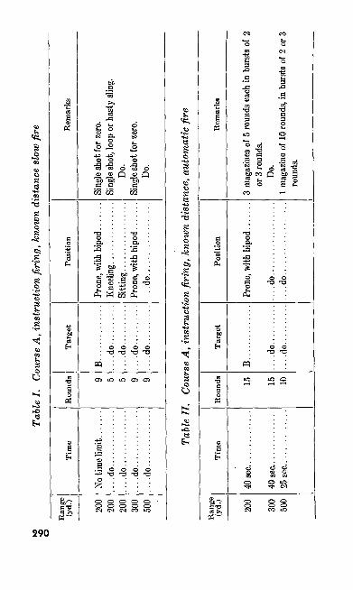
to
•o
oTa
ble
I. C
ours
e A
, ins
truc
tion
firin
g, k
now
n di
stan
ce s
low
fire
Ran
ge
(yd.
) ?nn 200 ?oo 300
500
Tim
e
....do..............
....
do
....
....
....
....
..d
o..
....
....
....
....do..............
Rou
nds q 5 5 9 9
Targ
et
B....... ..
....
....
.do.
......
......
.do.
......
.....
..d
o..
....
....
....do..........
Posi
tion
....
do
....
....
....
....
..
Rem
arks
Do.
Do.
Tabl
e II
. C
ours
e A
, ins
truc
tion
firin
g, k
now
n di
stan
ce, a
utom
atic
fire
Ran
ge(yd
.)
200
300
500
Tim
e
40 se
c. ..
....
....
...
40 se
c. ..
....
....
...
25 s
ec...
......
.....
Rou
nds 15 15 10
Targ
et
B..
....
....
....
....d
o....
......
....do..........
Posi
tion
....
do
....
....
....
....
....
..d
o..
....
....
....
....
Rem
arks
or 3
roun
ds.
Do.
roun
ds.
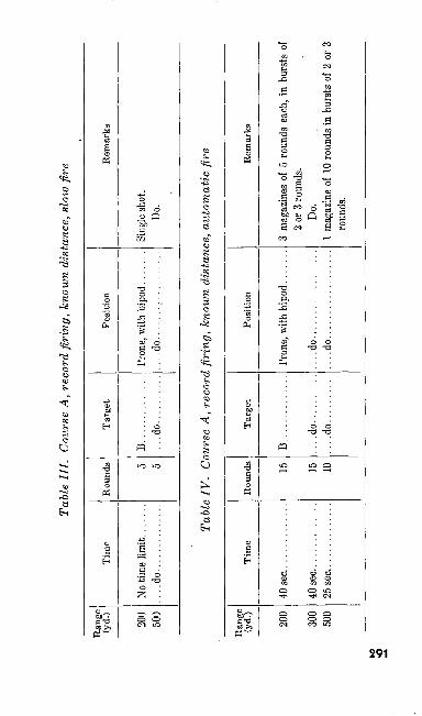
Tabl
e II
I. C
ours
e A,
rec
ord
firin
g, k
now
n di
stan
ce, s
low
fire
Ran
ge
(yd.
)
200
500
Tim
e
....do..............
Rou
nds 5 5
Tar
get
B. ......
......
....d
o..........
Pos
itio
n
....do..................
Rem
arks
Do.
Tabl
e IV
. C
ours
e A
, rec
ord
firin
g, k
now
n di
stan
ce,
auto
mat
ic fi
re
Ran
ge(y
d.) 200
300
inn
Tim
eR
ound
s 15 15 10
Tar
get
B. .............
....d
o....
......
....d
o..........
Posi
tion
....d
o..................
....d
o..................
Rem
arks
2 or
3 ro
unds
. Do
.
roun
ds.
K>
•O
137. COURSE Ba. General. Course B consists of four tables
and is fired when the range facilities for the stand ard course and course A are not available. The firing outlined in tables I and II is advisory only.
b. Qualification Scores. The total of your table III and table IV record scores determines your qualification as an automatic rifleman. The mini mum course B qualifying scores for the three classifications are:
(1) Expert automatic rifleman 145 points(2) Automatic rifle sharp
shooter ............... 125 points(3) Automatic rifle marksman 96 points
292
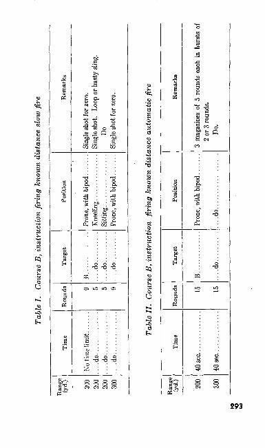
Tabl
e I.
Cour
se B
, ins
truc
tion
firin
g kn
own
dist
ance
slo
w fir
e
Ran
ge(yd
.)
200
200
200
300
Tim
e
No ti
me l
imit ..
....
.....do..............
....do..............
....do..............
Rou
nds 9 5 9
Tar
get
B..............
....d
o..........
....d
o....
......
....d
o..........
Posi
tion
Pron
e, wi
th b
ipod
....
...
Sit
ting.................
Pron
e, wi
th b
ipod
....
...
Rem
arks
Sing
le sh
ot fo
r zer
o.
DoSi
ngle
shot
for z
ero.
Tabl
e II
. Co
urse
B, i
nstr
uctio
n fir
ing
know
n di
stan
ce a
utom
atic
fire
Rang
e (y
d.) 200
300
Tim
e
4n QP
O
Rou
nds 15 15
Tar
get
B..
............
....d
o....
......
Posi
tion
....do..
....
....
....
....
Rem
arks
2 or 3
roun
ds.
Do.
•o h>
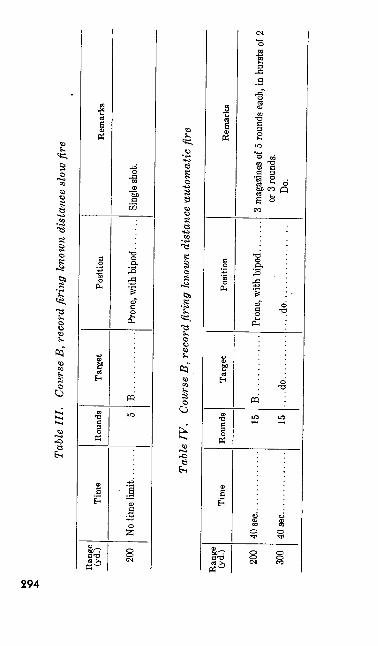
KO
O
Tabl
e II
I.
Cou
rse
B, r
ecor
d fir
ing
know
n di
stan
ce s
low
fire
Ran
ge(yd
.)
200
Tim
eR
ound
s 5
Tar
get
B.............
Posi
tion
Rem
arks
Tabl
e IV
. C
ours
e B,
rec
ord
firin
g kn
own
dist
ance
aut
omat
ic fi
re
Ran
ge(yd
.)
200
300
Tim
e
40 se
c. .............
Rou
nds 15 15
Tar
get
B.. ...........
....d
o....
......
Posi
tion
....do..................
Rem
arks
or 3
roun
ds.
Do.
138. COURSE Ca. General. Course C .consists of four tables
and is fired when the range facilities are not adequate for the standard or the A or B courses. The instruction firing outlined in tables I and II is advisory only.
6. Qualification Scores. The total of your table III and IV record scores determines your qualifica tion as an automatic rifleman. The minimum course C qualifying scores for the three classifica tions are:
(1) Expert automatic rifleman 175 points(2) Automatic rifle sharp
shooter ............... 150 points(3) Automatic rifle marksman 125 points
295
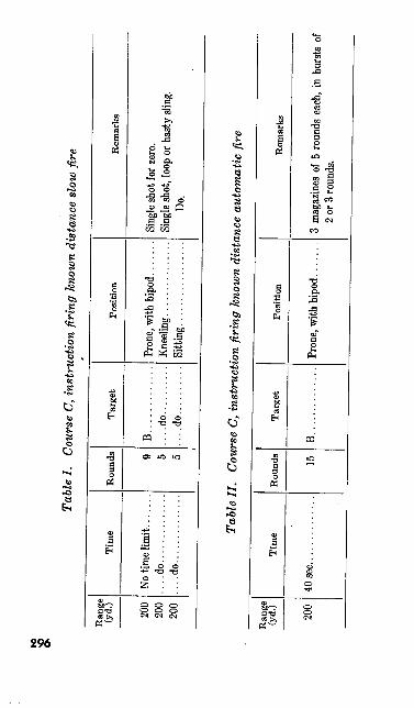
Tabl
e I.
Cour
se C
, ins
truc
tion
firin
g kn
own
dist
ance
slo
w fir
e
Ran
ge(yd
.)
200
200
200
Tim
e
....d
o..............
....d
o..............
Rou
nds 9 5 5
Tar
get
B. ............
....d
o....
......
....d
o....
......
Pos
itio
nR
emar
ks
Do.
Tabl
e II
. Co
urse
C, i
nstr
uctio
n fir
ing
know
n di
stan
ce a
utom
atic
fire
Ran
ge(y
d.) 200
Tim
e
40 s
ec. .
............
Rou
nds 15
Targ
et
B..............
Posi
tion
Rem
arks
2 or
3 ro
unds
.
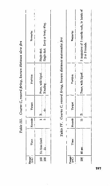
Tabl
e H
I. Co
urse
C, r
ecor
d fir
ing,
kno
wn
dist
ance
slo
w fi
re
Ran
ge(y
d.) 200
200
Tim
e
....
do
....
....
....
..
Bou
nds 5 5
Tar
get
B..
............
....d
o....
......
Posi
tion
Rem
arks
Tabl
e IV
. Co
urse
C, r
ecor
d fir
ing,
kno
wn
dist
ance
aut
omat
ic fi
re
Ran
ge
(yd.
)
200
Tim
e
40 se
c. ..
....
....
...
Rou
nds 15
Tar
get
B. .............
Posi
tion
Rem
arks
2 or
3 ro
unds
.
to <0 -J
139. COURSE Da. General. Course D consists of two tables
and is fired when range facilities required for the standard or the A, B, or C courses are not avail able or when training time and the availability of ammunition permit 1000-inch firing before in struction firing of the A, B, or C courses. The in struction firing outlined in table I is advisory only.
6. Qualification Scorces. Your table II record practice score determines your qualification as an automatic rifleman. The minimum qualifying scores for the three classifications are:
(1) Expert automatic rifleman 165 points(2) Automatic rifle sharp
shooter ............... 155 points(3) Automatic rifle marksman 120 points
298
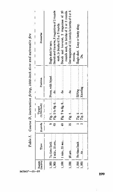
Tabl
e I.
Cou
rse
D, i
nstr
uctio
n fir
ing,
100
0-in
ch s
low
and
aut
omat
ic fi
re
to 8
Ran
ge
(inch
es)
1 nnn
1,000
1 nnn
1,000
1,000
1,000
Tim
e
....do.............
Rou
nds 40 40 15 5 5
Tar
get
(1,0
00-in
ch)
Fig.
1. .
........
Fig.
5 to
fig. 6
...
Fig.
7 to
fig. 8
...
Fig.
4..........
Fig.
2.. .
.......
Fig.
3..........
Posi
tion
....
do
..................
....
do..................
....
do..................
Rem
arks
each
, in
burs
ts of
2 or
3 ro
unds
.
roun
ds e
ach,
in b
ursts
of
2 or
3 r
ound
s.
roun
ds.
Do.
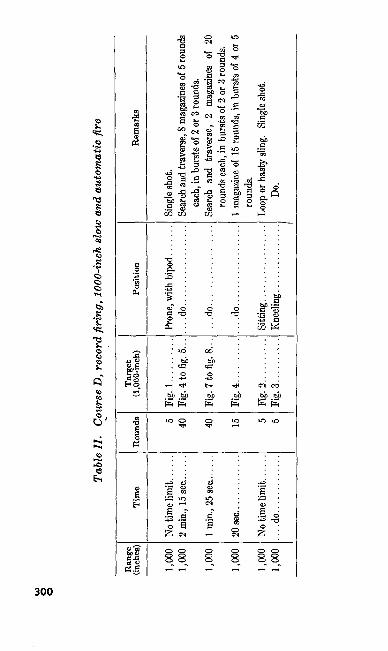
U) §
Tabl
e II
. Co
urse
D, r
ecor
d fir
ing,
100
0-in
ch sl
ow a
nd a
utom
atic
fire
Ran
ge(in
ches
)
1,00
01,
000
1,00
0
1,00
0
1,00
01,0
00
Tim
e
1 min
., 25
sec..
.. . .
.
20 s
ec...
... .......
....
do
....
....
....
.
Rou
nds 5 40 40
15 5 5
Targ
et
(1,0
00-in
ch)
Fig
.l.... ......
Fig.
7 to
fig. 8
. . .
Fig.
4..........
Fig.
2..........
Fig.
3.. .
....
...
Posi
tion
....do..................
....do..
....
....
....
....
....d
o..
....
....
....
....
Rem
arks
each
, in
burs
ts of
2 o
r 3 ro
unds
. Se
arch
and
tra
vers
e, 2
m
agaz
ines
of
20
roun
ds e
ach,
in b
ursts
of 2
or 3
roun
ds.
roun
ds.
Do.
140. TRANSITION FIRING-COURSES A, B, C, AND D
a. Transition tables VII and VIII of the stand ard course may be fired in courses A, B, C, and D. Where range facilities are not available, two alternate transition tables may be fired in lieu of tables VII and VIII. Table VI of the standard course should be fired in all courses if range facilities are available.
6. While alternate tables I and II are not fired for qualification, the automatic rifleman should attain a satisfactory score as indicated for each table. Those men not attaining a satisfactory score should be required to fire until they do, pro viding time and ammunition allowances permit.
c. Alternate transition firing is conducted on the known distance range and transition firing ranges according to the procedure explained in FM 23-5. The alternate transition tables are fired after known distance record practice and before firing combat exercises. The exercises are preceded by instruction in range estimation and aiming point.
301
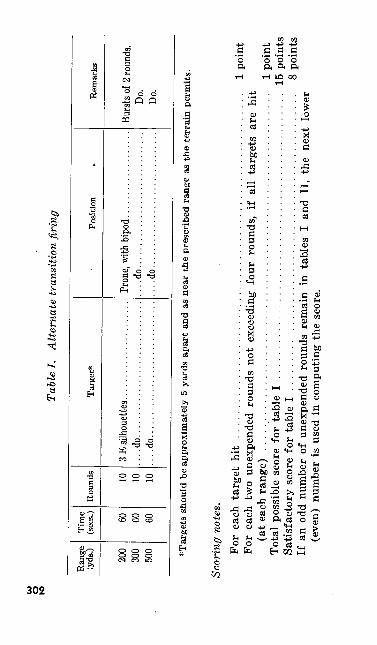
U) g
Tabl
e I.
A
ltern
ate
tran
sitio
n fir
ing
Rang
e (y
ds.)
200
300
500
Tim
e (s
ees.) 60 60 60
Roun
ds 10 10 10
Targ
et*
....do..............................
....do..............................
Posi
tion
»
....do.... ..........................
....do..............................
Rem
arks
Do.
Do.
*Tar
gets
sho
uld
be a
ppro
xim
atel
y 5
yard
s ap
art
and
as n
ear
the
pres
crib
ed r
ange
as
the
terr
ain
perm
its.
Scor
ing
note
s,Fo
r ea
ch t
arge
t hi
t ..........................................................
1 po
int
For
each
tw
o un
expe
nded
rou
nds
not
exce
edin
g fo
ur r
ound
s, i
f al
l ta
rget
s ar
e hi
t(a
t ea
ch r
ange
) ............................................................
1 po
int
Tot
al p
ossi
ble
scor
e fo
r ta
ble
I ................................................
15 p
oint
sSa
tisfa
ctor
y sc
ore
for
tabl
e I ..................................................
8 po
ints
If a
n od
d nu
mbe
r of
une
xpen
ded
roun
ds r
emai
n in
tab
les
I an
d II
, th
e ne
xt l
ower
(eve
n)
num
ber
is u
sed
in c
ompu
ting
the
sco
re.
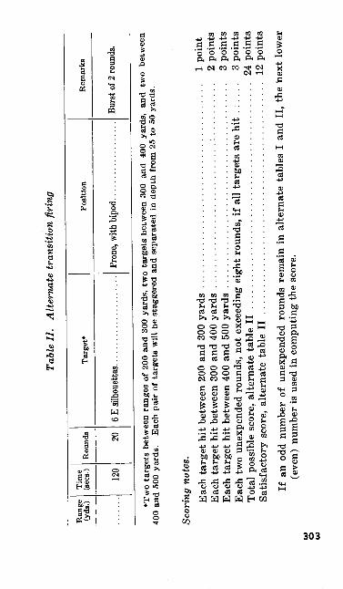
Tabl
e II
. A
ltern
ate
tran
sitio
n fir
ing
Ran
ge
(yds
.)T
ime
(see
s.) 120
Rou
nds 20
Targ
et*
Posi
tion
Rem
arks
*Tw
o ta
rget
s be
twee
n ra
nges
of 2
00 a
nd 3
00 y
ards
, tw
o ta
rget
s be
twee
n 30
0 an
d 40
0 ya
rds,
and
two
betw
een
400
and
500
yard
s. Ea
ch p
air
of ta
rget
s wi
ll be
sta
gger
ed a
nd s
epar
ated
in
dept
h fro
m 2
5 to
50
yard
s.
Scor
ing
note
s.Ea
ch ta
rget
hit
betw
een
200
and
300
yard
s ......................................
1 po
int
Each
tar
get h
it be
twee
n 30
0 an
d 40
0 ya
rds
................ ...........:.
.........
2 po
ints
Each
tar
get h
it be
twee
n 40
0 an
d 50
0 ya
rds
......................................
3 po
ints
Each
two
unex
pend
ed r
ound
s, n
ot e
xcee
ding
eig
ht ro
unds
, if
all t
arge
ts a
re h
it .:
....
3 po
ints
Tota
l po
ssib
le s
core
, alte
rnat
e ta
ble
II .
.........................................
24 p
oint
sSa
tisfa
ctor
y sc
ore,
alte
rnat
e ta
ble
II .
....
....
....
....
....
....
....
....
....
....
..
12 p
oint
s
If a
n od
d nu
mbe
r of
une
xpen
ded
roun
ds r
emai
n in
alte
rnat
e ta
bles
I a
nd I
I, th
e ne
xt l
ower
(e
ven)
num
ber
is us
ed in
com
putin
g th
e sc
ore.
O
U>
141. FAMILIARIZATION COURSEFive hours of preliminary instruction are pre
scribed for those men (other than automatic rifle men) who are required to familiarize themselves with the automatic rifle. The familiarization course is fired on the 200-yard known distance range. The course score is the total value of all target hits.
304
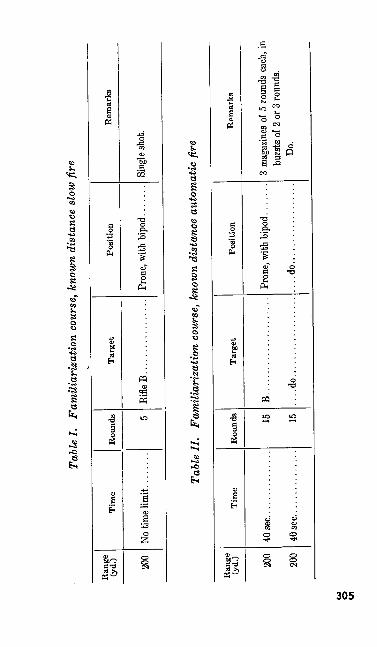
Tabl
e I.
Fam
iliar
izat
ion
cour
se, k
now
n di
stan
ce s
low
fire
Ran
ge(y
d.) 200
Tim
eH
ound
s 5
Tar
get
Rifle
B.................
Pos
itio
nR
emar
ks
Tabl
e II
. Fa
mili
ariz
atio
n co
urse
, kno
wn
dist
ance
aut
omat
ic fi
re
Ran
ge(yd
.) 200
200
Tim
e
40
aec.
....
....
....
..
Rou
nds 15 15
Tar
get
B. .....................
....do..................
Posi
tion
....do..................
Rem
arks
burs
ts of
2 or
3 ro
unds
. Do
.
o Ul
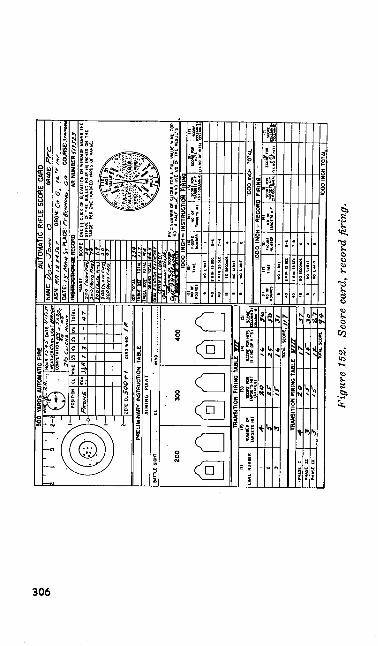
S
Fig
ure
152.
Sc
ore
card
, rec
ord
firin
g.
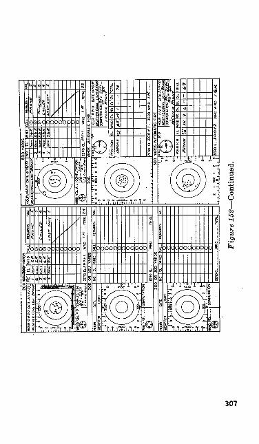
Fig
ure
152—
Con
tinue
d.
142. RECORD SCORESThe score card DA AGO Form 84 shown in
figure 152 is recommended for use in all fire courses when firing any one of the five courses for record. The score card is used for all instruction and familiarization firing (par. 131).
Section IV. RANGE FIRING
143. GENERALa. You start range firing as soon as you com
plete preparatory marksmanship training. Range firing consists of:
(1) Instruction firing which is the applica tion of the principles of marksmanship with live ammunition.
(2) Record firing which is the firing of a record course for qualification.
(3) Familiarization firing which is fired by those individuals not authorized to fire a record course for qualification.
6. Range firing begins with instruction firing which each automatic rifleman must complete be fore he begins record firing. Once record firing begins, it must be completed before you are per mitted to take any additional instruction firing. As a rule, no automatic rifleman fires for record on the same day that he does any instruction firing. However, when the time allotted to range firing is limited, the unit commander may author ize record firing on the same day.308
144. RANGE PERSONNELa. General. Officers and noncommissioned of
ficer assistants should be thoroughly oriented and assigned specific duties before going on the range.
b. Range Officer. The commanding officer usu ally designates a range officer at large installations and wherever the ranges are used frequently. The range officer is responsible for assigning ranges, designating danger areas, and closing roads leading into danger areas. He makes ar rangements for material and labor to maintain the ranges and directs and supervises all neces sary repairs to shelters, butts, targets, firing points, and telephone lines. He provides for the safety of the target detail and, when necessary, he provides range guards and instructs them in the methods to be used for the protection of life and property within the danger area.
c. Range Noncommissioned Officer. Noncom missioned officers and any other assistants that the commanding officer may deem necessary are detailed permanently during the range season to assist the range officer. These men are responsible to the range officer for seeing that the equipment in the target pits is in serviceable condition, that the desired number of targets is ready for use at the appointed time, and that all target and pit de tails are provided with proper flags, marking disks, pasters, and spotters.
145. UNIT RANGE PERSONNELa. Unit Range Officer. If there is no regularly
assigned range officer, the commanding officer of309
the unit firing on the range may appoint a unit range officer. The duties of the unit range officer are similar to those duties listed in paragraph 144.
b. Officer in Charge of Firing and Safety. An officer in charge of firing is designated by the com manding officer of the unit firing on the range. It is desirable that the officer in charge of firing be the senior officer of the unit on the range. This officer, or his assistant, will be present during all firing. He is responsible for the proper and safe conduct of range firing.
c. Pit Officer. An officer is placed in charge of the pit detail and pit operation. This officer is responsible to the officer in charge of firing for the discipline, efficiency, and safety of the pit de tail. The pit officer makes sure that targets and other equipment used in the operation of the pit are on hand and are serviceable.
d. Pit Detail. Enough enlisted men are as signed to the pit detail to operate the targets and the telephones.
146. ORGANIZATION OF THE FIRING LINEa. General. The firing line is organized for
the safe and orderly conduct of range practice and for the supervision of the entire firing line by the officer in charge of firing. The distances shown in figure 153 may be modified by the officer in charge to meet local conditions.
b. Line of Scorers. These men are stationed to the rear of the automatic rifleman being scored. The line of scorers is usually on the. slope or at the top of the slope of the firing line. Scorers are generally used only during record firing.310
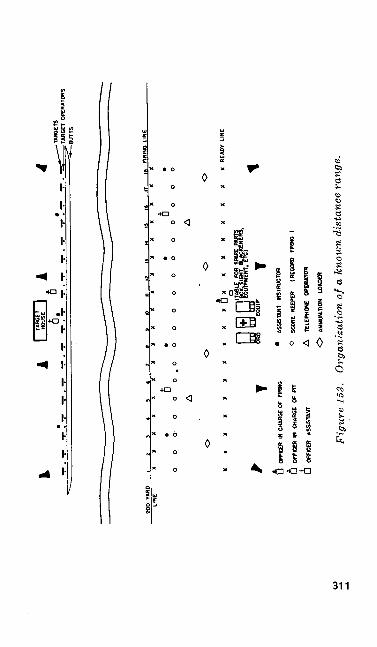
^TA
RG
ETS
? T
ARG
ET O
PERA
TORS
-BU
TTS
ZOO
YAR
D i
i 3
4 *
« r
«——
—»
10—
——
U——
—12
——
—a
——
—U—
——
U——
—11
——
—U—
——
H O
RI"
° "H
E
LIN
E X
XX
XX
XX
XX
XX
XX
XX
XX
X
ooo-ooo.oooooooooooo
A
A
o
o
o
o
XX
XX
XX
XX
XX
JJX
XX
XX
XX
XI
U
OFF
ICER
IN
CHA
S6E
OF
FIR
MS
U
OFF
KXR
«
CHAR
GE
OF
PIT
fiO
FFIC
ER
ASSI
STAN
T
•
ASSI
STAN
T W
STRU
CTO
R
O
SCO
RE
KEEP
ER
(REC
OR
D
FIR
MS
)
A
TELE
PHO
NE
OPE
RATO
R
O
AM
MU
NIT
ION
LO
ADER
Fig
ure
153.
O
rgan
izat
ion
of a
kno
wn
dist
ance
ran
ge.
c. Line of Telephone Operators. These men are stationed ten yards in rear of the firing line. There should be one telephone operator to every ten firing points.
d. Line of Ammunition Tables. This line is located by the officer in charge of firing at his discretion with regards to safety. A good loca tion is between the ready line and the telephone line. There should be one ammunition table for every five firing points.
e. Ready Line. This line is located ten yards in rear of the line of telephone operators. The ready line is the line where the next firing order for each target is awaiting its turn to fire.
/. Line of Automatic Rifle Rests and Cleaning Racks. This line is five yards in rear of the ready line.
g. Control Stand. The control stand for the officer in charge of firing is located ten yards to the rear of the center of the firing line. It must be so located that the officer in charge of firing can observe and control the operation of the range.
h. Ordnance and Aid Men. The ordnance men and medical corps men are located in rear of the center of the ready line.
i. Public Address System. If a public address system is available, it is set up near the officer in charge of firing. Loud-speakers are placed at intervals to the rear of the ready line so that all troops can hear the fire commands and other di rections from the officer in charge of firing.
312
147. SUBJECTS COMMON TO INSTRUCTION AND RECORD FIRING
a. Uniform.(1) General. The uniform that is worn
during firing is prescribed by the unit or higher commander. Normally, fatigue clothes are worn. The automatic rifle belt is worn by the firer during all firing.
(2) Use of pads and gloves. You are en couraged to use pads for the protection of your shoulder, elbows, and arms dur ing known distance firing. The pads ease the shock of recoil and provide com fort so that you can concentrate on shooting. Shooting coats are permitted. If these items are not available, other padding may be used if they are of mod erate size and thickness. You may not use pads of such size, thickness, or con struction that form an artificial support for the weapon. You are not allowed to use a hook or any other device on the sleeve to keep the sling in place. Gloves may be worn provided they are not padded so as to form a support for the automatic rifle.
b. Use of Instruments. Binoculars and spot ting scopes are authorized. Instruments may not be used for determining the velocity and direction of the wind during record firing.
c. Restrictions on the Use of the Automatic Rifle. You will use the automatic rifle as issued
313
by the Ordnance Department. No additional ap pliances or devices like shades for the sights may be used. The sights should be blackened during all range firing. Weapons and appliances which may have been issued for test purposes will not be used when firing for classification.
d. Trigger Pull. The trigger pull of the auto matic rifle must be at least 6 pounds and not more than 10 pounds. The trigger pull should be tested before range firing.
e. Ammunition. Only ammunition issued by the Ordnance Department will be used. No one will be issued more than the prescribed number of rounds during record firing.
/. Use of the Sling. Additional holes may be punched in the sling. The sling is used only to support the arm when firing from the sitting and kneeling positions. The sling is not used in the prone position. When firing from the crouch position, a special adjustment of the sling is used.
g. Range Precautions. The safety regulations that must be observed when handling and firing the automatic rifle are covered in paragraphs 231- 235.
h. Action in Case of a Damaged Automatic Rifle. Should a breakage occur, the automatic rifle will be repaired or replaced. If repairs in volve the sights or if a different automatic rifle is used, you will be allowed to rezero the repaired automatic .rifle or zero the new weapon before firing the exercise.
i. Loading the Automatic Rifles. Initially, au tomatic rifles are loaded only on command. There- 314
after, they are loaded at will as long as the auto matic rifleman is in the firing position and until the command CEASE FIRING is given.
j. Use of Telephones.(1) General. Telephones for the firing line
and pit are used only for official commu nications. Only the officer in charge of firing, or one of his assistants, may ask for information over the telephone con cerning the name or organization of a target operator on any particular target. Pit personnel may not inquire the name of any particular firer.
(2) Expressions used over the telephones. The following expressions should be used over the telephone:
(a) When a shot has been fired and the target has not been withdrawn for marking—MARK TARGET ........
(6) When a spotter has been placed in the target but the target has not been disked—DISK TARGET ........
(c) When the target has been marked but the value of the shot was not under stood—REDISK TARGET ........
(d) When fewer shots were marked than were fired—CHECK TARGET ......FOR ....... SHOTS. (Ask that acheck be made for the total number of rounds fired.)
(e) Fire commands as given by the officer in charge of firing. An example of .
947041°—51—21315
these commands is: READY ON THE RIGHT? READY ON THE LEFT? READY ON THE FIRING LINE.
k. Coaching. During instruction firing, your coach will be able to help you in many ways; you must strive to follow his advice. During record firing there are certain limitations imposed on the coach. These restrictions are explained in para graph 156. If enough experienced men are avail able, you will be assigned a well-trained noncom missioned officer to serve as your coach. Other wise, one of your buddies will be your coach and you in turn will act as his coach. Most organiza tions assign especially qualified coaches to several extra targets on one end of the firing line. Firers who are having difficulty may be sent to these experts for additional instruction. During range firing, the coach performs those duties he was as signed in preparatory marksmanship training as well as making sure that—
(1) Your sights are blackened properly and set for the correct elevation and windage.
(2) Your ammunition is free from dirt.(3) Your magazines are clean, operate cor
rectly, are placed into your belt in the prescribed manner.
(4) You load the initial (first) magazine and change subsequent magazines cor rectly.
(5) You replace the magazines in the auto matic rifle belt as soon as the firing ex ercise is complete.
316
(6) You plot your shots and enter your score on your score card.
(7) You observe' all safety precautions. Your coach must be alert that you keep your weapon pointed down range in the event the weapon continues to fire after the trigger is released (a runaway gun). This malfunction is rare.
I. Score Card. You will maintain the score card during all of your firing. The score card serves as a history of your weapon. You must keep your own score card.
148. INSTRUCTION FIRINGInstruction firing involves the use of live am
munition in applying the principles taught during preparatory marksmanship training. Instructon firing is part of each of the five courses. Within the ammunition allowances of each unit, the num ber of shots to be fired at each range for instruc tion firing is determined by the organizational commander.
a. Slow Fire. The first few rounds fired dur ing instruction firing on the range should be fired single shot and from the prone position. At first, you should be interested in developing your ability to fire a small shot group and not in ob taining high scores.
b. Automatic Fire. No firer should be allowed to fire automatic fire until he has fired a satisfac tory shot group at slow fire. During automatic fire you must fire in short bursts of two or three
317
rounds each except where specifically indicated otherwise. Here again the importance of a good position and a tight grip on the automatic rifle cannot be overemphasized.
c. Method of Conducting Instruction Firing. Instruction firing is conducted in a manner simi lar to record firing (pars. 153 and 154).
149. USE OF DUMMY CARTRIDGES IN INSTRUC TION FIRING
Dummy cartridges may be used during instruc tion firing. The use of the dummy cartridge is an excellent means for detecting flinching and failure to follow through. To use the dummy cartridge during slow fire, the coach tells the firer to turn his head away from the automatic rifle. Then the coach may load a dummy car tridge, a live cartridge, or no cartridge at all into the chamber. In this way, the firer does not know if his weapon is loaded and the coach can check the firer for flinching and follow through. Dummy cartridges may be used in instruction firing dur ing automatic fire. Additional time must be al lowed if they are used. This training is needed to develop correct trigger manipulation and fol low through. The importance of using dummy cartridges cannot be overemphasized.
150. ZEROINGa. Obtaining the zero of your iveapon is one
of the objects of instruction firing. The auto matic rifle is zeroed at each range and the zero is recorded on your score card. The position of318
the bullet hole on the 1,000-inch target or the posi tion of the spotter on targets at greater ranges enables you to compute necessary corrections in elevation and windage using the deflection and elevation rule.
b. To zero the automatic rifle for the 1,000- inch Range, set the rear sight at zero windage and 400 yards elevation. Corrections are made in clicks by the elevation and windage knobs to bring the subsequent shots into the center of the bull's eye. As soon as you have fired three rounds for a shot group and the firing line has been cleared, the officer in charge of firing directs you to move down to your target to examine the shot group. You then determine what corrections, if any, are necessary and place the elevation and windage corrections on the rear sight. The remaining six shots are fired in two groups of three rounds each. Each of these groups is fired in the same manner as the first group. One click of windage or elevation moves the strike of the bullet one inch on the target at 1,000 inches. Part clicks of windage can be taken; only full clicks of ele vation can be taken.
c. To zero the automatic rifle at 200 yards, raise the elevation scale so that the index line is as near as possible to the two hundred yard setting. Assuming that the day is normal and there is no wind blowing, proceed as follows:
(1) Assume the proper position, load a single round into the chamber, take the correct sight picture, and fire the round.
319
(2) Call the shot and enter your call on the score card.
(3) Fire two more rounds following the same procedure.
(4) When the target is marked, enter the location of the three shots on the target on your score card.
(5) Determine how far the center of this shot group is from the center of the bull's eye.
(6) Using the elevation and deflection rules, make a sight change on the rear sight for elevation and windage to bring the center of your next shot group into the center of the bull's eye.
(7) Fire three more rounds following the same procedure used for the first group.
(8) Plot the location of the second shot group. Make a sight change, if neces sary, to move the center of this group into the center of the bull's eye.
(9) Fire the third group. This group should be in the center of the bull's eye.
(10) The setting that you have on the rear sight is the zero of your automatic rifle at 200 yards (if it is a normal day with no wind blowing). Record this setting as your 200 yard zero on your score card.
d. To zero the automatic rifle at 300 yards, place the 200-yard zero sight setting on your au tomatic rifle and add one click of elevation. Fire320
nine rounds in groups of three rounds each, fol lowing the procedure used for zeroing at two hundred yards.
e. To zero the automatic rifle at 500 yards, place the 300-yard zero sight setting on your au tomatic rifle and add one click of elevation. Pro ceed in the same manner as for zeroing at 200 and 300 yards.
/. To zero the automatic rifle on a day ^vhen the wind is blowing, you must make the necessary changes in your sight setting until the center of your shot group is in the center of the bull's eye. Then determine the value of the wind, in clicks,
RxV -by using the wind formula ____ subtract the
40result of this formula from the windage setting. The sight setting you have left on the rear sight, both in elevation and windage, is the zero setting for that range on a day when no wind is bloiving. You will very seldom fire on the range when a wind is not blowing.
151. RECORD FIRINGThe purpose of record firing is to test the
soldier's skill and to determine his qualifications as an automatic rifleman. The qualification courses are outlined in each automatic rifle course. The qualification course to be fired by the individual is as directed by army regulations or training programs.
321
152. RECORD FIRING SCORE CARDSThe scorer keeps a score card for each auto
matic rifleman. The scorers generally operate from a position directly to the rear of each firing point. Men selected to serve as scorers must be thoroughly oriented concerning their duties and responsibilities. When record firing is completed, the officer in charge of firing has all score cards collected, checked, signed, and turned over to the organization commander.
153. METHOD OF CONDUCTING RECORD SLOW FIRE ON KNOWN DISTANCE RANGES
One automatic rifleman in each order is as signed to a target. When all firers in an order are in position and ready to fire, the officer in charge of firing gives the command: ONE ROUND (or ONE MAGAZINE OF FIVE ROUNDS) LOAD, COMMENCE FIRING. Be cause the automatic rifle is a team weapon, the firer repeats the fire command. If you are firing a magazine of five rounds, attempt to fire single shots. When the value of each shot is marked in the pits, your scorer announces, in a tone loud enough for you to hear, your name, the number of the shot, and the value of the hit. If a miss was signaled and you have any doubts concern ing the shot, you should challenge the value of the shot at this time. In this case, the officer in charge of firing will direct the pit officer to check the target in question. The scorer records the score as soon as your target has been rechecked.322
At the end of firing, the officer in charge of firing commands: CEASE FIRING, CLEAR WEAP ONS.
154. METHOD OF CONDUCTING RECORD AUTOMATIC FIRE ON KNOWN DIS TANCE RANGES
a. One automatic rifleman in each order is assigned to a target. All automatic fire is con ducted from the prone position. If more than one magazine is used during an automatic fire exer cise, all magazines (other than the initial maga zine) that are to be loaded into the weapon are placed in the automatic rifle belt. All firers are given an opportunity to check their position and to sight in on the target before the exercise be gins. When all firers have checked their posi tion, the targets are withdrawn and a red flag is displayed from the center of the pits. The firers and coaches remain down and in position.
b. The fire command is now given by the officer in charge of firing: ONE MAGAZINE OF FIVE ROUNDS, LOAD; IN SHORT BURSTS; READY ON THE RIGHT? READY ON THE LEFT? READY ON THE FIRING LINE. At the command READY ON THE FIR ING LINE, the red flag in the pit is waved for 5 seconds and then lowered. Five seconds after the flag is lowered, the targets are raised and re main exposed for the prescribed length of time. This time element starts when the targets reach their highest point. At the end of the time limit, all targets are lowered and the officer in charge of
323
firing commands: CEASE FIRING. All targets are again raised to allow the firing of alibis. You are only allowed to fire those rounds which are left because of a stoppage that is not your fault. A representative of the officer in charge of firing must examine each stoppage and supervise the firing of all alibis. As soon as all alibis are fired, the officer in charge of firing commands CEASE FIRING, CLEAR WEAPONS.
c. All targets are marked. As the targets are disked, the scorer announces each shot as fol lows :
(1) Target number (number of the target).(2) 1 five, 2 fives, 3 fives, 4 fives, 5 fives, 6
fives, 7 fives, 8 fives.(3) 1 four, 2 fours, 3 fours, 4 fours, 5 fours,
6 fours.(4) 1 three.
d. As soon as the target has been marked, your scorer counts the number of shots disked. If there are more hits than the prescribed number of rounds you fired, your scorer requests that the target be redisked. Should you have more than the prescribed number of hits, you must refire the exercise unless all shots on your target are of the same value. Generally, the targets are left up for approximately 1 minute after marking. This gives each firer time to plot the shot group on the score card. The score card is kept during all firing. The targets may remain up longer if directed by the officer in charge of firing.324
155. METHOD OF CONDUCTING SLOW AND AUTOMATIC FIRE ON THE 1000-INCH RANGE
Firing at this range is conducted like known distance range firing with the following excep tions :
a. During automatic fire the commands COM MENCE FIRING and CEASE FIRING are used because the targets remain exposed at all times.
b. The target is marked only after all slow fire and automatic fire is completed.
156. REGULATIONS REGARDING RECORD FIR ING
The record course is normally fired for quali fication and, for this reason, additional regulations are imposed on firing. Some of these regulations are:
a. Members of the pit detail should not know who is firing on any particular target and they should make no attempt to obtain this informa tion. Personnel on or in rear of the firing line will not transmit this information to members of the pit detail.
6. Coaching is permitted. The coach may not touch any part of your body or weapon while you are firing.
c. Warming or fouling shots are not per mitted.
d. Cleaning is permitted only between firing exercises.
325
e. When a slow fire exercise is interrupted through no fault of your own, you will be allowed to complete the exercise at the first opportunity.
/. You may challenge all signals of misses.(1) Before a miss is signaled during slow
fire, the target operator must withdraw your target from the raised position and carefully examine it. If the pit officer or one of his assistants is available, he will examine the target. Should your target be raised and a miss signaled, it is presumed that the target has been checked by the target operator. If you challenge the miss, the target will be withdrawn and rechecked, preferably by an officer. After being checked, the tar get is raised and the result is disked.
(2) As you are firing a fully automatic weapon, it is possible that a short burst may be fired unintentionally during slow fire. All such shots are marked, disked, and scored. If more than one shot is fired in slow fire and all shots are not marked and disked, have the telephone operator request that your target be checked for the total number of shots fired.
(3) If you challenge after your target is marked during automatic fire, the target may be withdrawn again and reexamined for the purpose of determining possible corrections in the original marking.
326
After a challenge, the target may be examined for misses (preferably by an officer) before the target is raised for disking.
g. All shots that you fire after taking your place on the firing line are considered a part of your record score. This applies regardless of whether your weapon is directed toward the target or is fired accidentally.
h. If you fire on the wrong target, each shot fired on it is entered as a miss on your score card regardless of what the value of the shots may be. You receive credit only for those hits which you fire on your own target.
i. During slow fire, if more than one shot strikes the target at nearly the same time, all shots are marked. When more shots than you actually fire are disked on your target, you receive credit for the hits having the highest value. No record is made of the other hits.
j. When you have more hits on your target than the number of rounds you fire in an auto matic fire exercise, you are required to refire the exercise. However, if all hits are of the same value, the target is marked and you are given credit for each round you fire.
k. If the target is withdrawn just as you. fire a shot during slow fire, report this fact at once to the officer in charge of firing or to one of his assistants. The complaint will be checked and, if the case is as represented, you will be allowed to fire again. Your scorekeeper will be directed to
327
disregard your last shot. During automatic fire exercises, you are allowed to refire the exercise if your target is withdrawn too soon.
I. In case of a stoppage during automatic fire, you must apply the first phase of immediate ac tion and attempt to finish the exercise. If this action does not eliminate the stoppage, raise your hand and call STOPPAGE. The officer in charge of firing or one of his assistants will in vestigate the cause of the stoppage. If it is de termined that the stoppage was caused through some fault or neglect on your part, you will not be allowed to complete the exercise. You receive credit only for the score made from the number of rounds fired. If it is determined that the stoppage was caused through no fault of your own, and if time and the ammunition allowance permit, you may be allowed to refire the entire exercise. If time and ammunition are not available, you will be allowed to complete the exercise on the basis of two seconds for each round that remains to be fired. If a change of magazines is required, four additional seconds are allowed for each magazine that must be changed. In no case will you be given any information regarding the previous hits on the target until the exercise is completed.
m. Each cartridge that is not fired is recorded as a miss. In case the number of hits marked is more than the number of rounds fired, you re ceive credit for the hits of the highest value, but only for the number of rounds that you fired.
n. If, through no fault of your own, your weapon is damaged while firing, your last shots328
are disregarded and the target is not marked. You refire the exercise after your automatic rifle is repaired.
o. Any shot cutting the edge of the bull's eye is signaled and recorded as a hit in the bull's eye. A shot touching a line separating two scor ing spaces is scored as a hit in the higher scoring space.
157. FIRE COMMANDS
a. General. Each fire command you receive on the range follows a set form. Sample fire com mands for slow and automatic firing on the 1000- inch and known distance ranges are listed below. Alternate words for parts of these commands are shown in parentheses.
b. Fire Commands for the 1000-inch Range.(1) For zeroing.
ONE ROUND, LOAD; FIGURE NUMBER ONE; COMMENCE FIRING; CEASE FIRING.
(2) For sloiv fire.ONE MAGAZINE OF FIVE ROUNDS,
LOAD; FIGURE NUMBER ONE (TWO or
THREE) ; SINGLE SHOT; COMMENCE FIRING; CEASE FIRING.
329
(3) For automatic fire.ONE MAGAZINE OF FIVE (FIF
TEEN or TWENTY) ROUNDS, LOAD;
FIGURE NUMBER FIVE TO FIGURE NUMBER SIX (FIGURE NUM BER FOUR or FIGURE NUMBER SEVEN to FIGURE NUMBER EIGHT) ;
IN SHORT BURSTS; (LONG BURSTS in the fifteen round exercises);
READY ON THE RIGHT? READY ON THE LEFT? READY ON THE FIRING LINE;
COMMENCE FIRING;CEASE FIRING.
c. Fire Commands for the Known Distance Range.
(1) For zeroingONE ROUND, LOAD; COMMENCE FIRING; CEASE FIRING.
(2) For slow fire.ONE MAGAZINE OF FIVE ROUNDS,LOAD;
SINGLE SHOT; COMMENCE FIRING; CEASE FIRING.
(3) For automatic fire.ONE MAGAZINE OF FIVE (TEN)
ROUNDS, LOAD; IN SHORT BURSTS;
330
READY ON THE RIGHT? READY ON THE LEFT? READY ON THE FIR
ING LINE; CEASE FIRING.
d. Explanation of Fire Commands.(1) READY ON THE RIGHT (LEFT).
This command is used to determine whether all firers on the right (left) por tion of the firing line are prepared for the firing exercise. If you are not ready, your coach raises his hand and calls NOT READY ON TARGET ........
(2) READY ON THE FIRING LINE. This command means that all men on the fir ing line are prepared for the firing ex ercise. To the officer in charge of the pit detail, this command is a. signal to wave the red flag from the center of the line of target frames.
(3) COMMENCE FIRING. This command grants permission to start firing. In known distance firing, it is used only for slow fire exercises. This command is used in all 1000-inch range fire com mands.
(4) CEASE FIRING. This command is given at the conclusion of an exercise or at any time that an unsafe condition arises. On the command CEASE FIR ING, you must stop firing immediately. Anyone may give this command.
947041°—51—22331
(5) CLEAR WEAPONS. This command is also given at the conclusion of a firing exercise and in all other cases when it is necessary for safety reasons. On this command you cock your weapon and at the same time remove the magazine; then press the trigger allowing the oper ating parts to move forward. The as sistant instructors personally check to see that each automatic rifle is clear on those firing points that they control.
158. PIT OPERATION AND ORGANIZATIONOne of the basic contributions to good shoot
ing is efficient operation of the targets by the pit detail. At one time or another, you will assist in the operation of the pits. You may be a target operator, a telephone operator, or a noncommis sioned officer assisting the pit officer. Whatever your job may be, it is important for efficient pit operation.
a. If possible, the pit detail is provided by a unit other than the one firing. This is especially desirable for record firing. Although it is de sirable to have three target operators for each two targets, the pit can be run efficiently with only one operator per target. In addition to target operators, an operator must be provided for each pit telephone. Normally, there is one telephone in the pits for each ten targets. Officers and non commissioned officers are assigned to supervise the pit detail. For efficient pit operation, one officer should be assigned to every twenty-four332
targets and one noncommissioned officer to every six targets.
6. The officer in charge of the pit is responsi ble for the safety of the pit detail and for the efficient operation of the targets. He arrives in advance of the pit detail and the firing unit to see that the range equipment is in working order and ready to be used. He knows the num ber of men firing, the number of targets needed, and the number of men he has to operate the targets and telephones.
c. As soon as the pit detail arrives at the pits, the officer in charge explains and demon strates the operation of the target frame and Ihe use of the three-and five-inch spotters and the marking disks. The short-range disk is used for 200- and 300-yard firing, and the midrange disk is used for 500-yard firing. The midrange disk as well as the five inch spotters may be used at the 200 and 300 ranges during periods of poor visi bility.
159. TARGET MARKINGa. Use of the Spotter. In known distance fir
ing, the firer cannot see where the shots hits the target. To indicate the exact location of the hit, place a spotter in the bullet hole. Use the 3-inch spotters when firing is conducted at 200 and 300 yards. Use the 5-inch spotters when the firing is conducted at 500 yards. When the shot hits target outside of the bull's eye, place the spotter in the bullet hole with the black side of the spotter exposed to the firer. When the shot hits or cuts
333
the edge of the bull's eye, place the spotter in the bullet hole with the white side of the spotter ox- jposed to the firer.
b. Signaling the Value of a Shot. The value of a shot on the target is indicated as follows:
(1) A five (bull's eye) by a white disk.(2) A four by a red disk.(3) A three by a white disk with a black
cross.(4), A miss by a red flag.(5) A ricochet is not counted as a hit and
is indicated as a miss.
c. Use of the Disk and the Red Flag to Mark a Shot. To mark:
(1) A five or four—raise the disk to the upper right hand corner of the target and then lower it over the center of the spotter.
(2) A three—raise the disk to the upper left hand corner of the target and then lower it over the center of the spotter.
(3) A miss—move the flag slowly across the front of the target once for each miss. During instruction practice, it is advis able to place a spotter in the bullet hole on the target even though the shot may be a miss outside of the three ring yet on the target.
d. Operating and Marking the Targets While Zeroing. While zeroing, the automatic rifleman fires three rounds to form a group. The target334
is left up until the officer in charge of the pit orders it withdrawn. After withdrawing the target, place spotters in the three holes. Then raise the target and disk each hit. Mark the hits of the highest value first, being careful to expose the correct side of the disk. Mark the hits slowly to avoid confusing the firer and his scorer. When one spotter is used to cover more than one hit, place the disk over the spotter the required num ber of times. After disking one hit, raise the disk to the upper right (or left) corner before mark ing the next shot. If the shot is a miss, indicate it by waving the red flag as explained in c above. As soon as the three shots have been disked, lower the target. Remove the three spot ters, paste the bullet holes, and raise the target so the next shot group may be fired.
e. Operating and Marking the Target During Slow Fire. Withdraw and mark the target for each shot. To give good pit operation you must remain alert. Watch and listen for the bullet to strike the target. When your target is hit, pull it down and place a spotter in the hole. Always check the target for more than one hit, because several shots may have been fired. If there is more than one hit, place a spotter in each bullet hole and disk the hits as required. The spotters are left in the target until the next shot is fired. Each time the target is lowered, place the spotter in the new hole, and paste the old hole. If the hit is in the bull's eye and the spotter inter feres with the automatic rifleman's sight picture,
335
the firer may request that the spotter be removed and the bullet hole pasted.
/. Operating and Marking the Targets Dur ing Automatic Fire. During an automatic fire exercise, you must stand by your target at all times, as the time allowed for the exercise is short. Before the exercise starts, you are told to raise your targets. This allows the automatic rifleman time to check his aim and position. Later, the pit officer will tell you to withdraw the tar get and stand by for the next command. That command will be to raise all targets. A whistle may be used for giving this command. All tar gets should be raised at the same time. The pit officer times the exercise, starting when the tar gets reach their highest point. Several seconds before the end of the exercise, the pit officer in structs STAND BY YOUR TARGETS. The com mand, TARGETS DOWN, is given so that the targets are lowered just when the time is up. All targets should be lowered at the same time. Normally, the targets are raised again before marking so that those firers who had stoppages may fire their alibis. When marking the target for an automatic fire exercise, you only need to place enough spotters in the target to indicate the location of the shot group to the firer. When disking the target, disk every hit. Write the number of fives, fours, threes, and misses at the bottom of the target. This is helpful in case the firer requests a redisking of the target. If there are more than the authorized number of hits on your target, have the target checked by the336
officer in charge of your section of the pits. After checking, he will tell the officer in charge of the firing line the number of hits on the target. Gen erally, you will be directed to paste the bullet holes and raise the target again so that the firer may refire the exercise.
160. PIT EQUIPMENTa. All equipment necessary for marking and
pasting the targets is found in the target house. For a list of the equipment to be used in the opera tion of the pit, see paragraph 162.
b. The target is pasted on target cloth which is mounted on a wooden target frame 6 feet square. This frame is easily broken and the target is easily punctured, therefore, it is ad visable that two men carry the target and place it in the target carrier.
c. A movable wooden or steel target carrier supports the target frame. A carrier counter weight balances the target. This counterweight may be another target or a solid weight. In all cases, the carrier must be tied to the frame when emplacing or removing a target. Some target carriers have a rope tied to the bottom to aid in raising and lowering the target. This rope can be used to tie the carrier down when removing the target from the carrier. If this is not done, the counterweight may drop and injure the men or damage the target equipment. If another target is used as a counterweight, the blank side is faced toward the firing line.
337
161. PIT SAFETY PRECAUTIONSThe following safety precautions must be ob
served while you are working in the pit:a. Stay between the line of targets and the
butts.b. Do not expose any part of your body above
the butts.c. Be careful that you do not injure yourself
when operating the targets.d. Be careful when handling the disk that you
do not strike other target operators nearby. When the disk is not in use, be sure that it is secure so that it will not fall and strike anyone. Be sure that no part of the disk is above the butts during firing.
e. Do not leave the pit until the firing line is clear. Only the officer in charge of the pits may authorize you to leave. He does this only after he has received a clearance from the officer in charge of firing.
Section V. EQUIPMENT, TARGETS, AND RANGES
162. EQUIPMENT LISTThe equipment needed for preparatory marks
manship and known distance range firing is listed below. Some known distance range equipment is used on the firing line and some is used in the target pits. The equipment required for transi tion firing is listed in paragraph 185.338
a. Preparatory Marksmanship Equipment.(1) One numbered stake per four soldiers.(2) One automatic rifle rack per 24 sol
diers (rack holding 12 automatic rifles).(3) One 1000-inch target, United States
rifle, caliber .30, Ml, per 4 soldiers.(4) One aiming stake (with 1000-inch
bull's eyes painted or tacked on) per 8 soldiers.
(5) One automatic rifle rest (box) per 4. soldiers.
(6) One sighting and aiming bar, com plete, for every 2 soldiers.
(7) One M15 sighting device per 4 sol diers.
(8) One box with white paper, tacked on. per 4 soldiers.
(9) One bull's eye disk per 4 soldiers.(10) One pencil per '4 soldiers.(11) One table.(12) Five cleaning rods.(13) One first aid box.(14) One spare parts box.(15) One progress chart to record the
progress of all soldiers individually.(16) Trash containers (one per 40 points).(17) Carbide lamps, with carbide and
water. Other sight blackening equip ment may be used if lamps are not avail able.
339
(18) Waste for cleaning purposes.(19) Blackboards, chalk, and erasers.(20) Instructional charts.(21) Public address system (if available).
b. Range Equipment at the Firing Line.(1) Ammunition.(2) Carbide lamps, with carbide and water.
Other sight blackening equipment may be used if lamps are not available.
(3) Tables (one per ammunition loader).(4) Chairs or stools (one per firing point,
telephone operator, and ammunition loader).
(5) Binoculars (one per point for use by the coach or scorer at the 500-yard line).
(6) Score cards (one per automatic rifle man).
(7) Cleaning and preserving materials.(8) Indelible pencils (one per point for use
during record scoring).(9) Brass containers (one per 10 points).(10) Trash containers (one per 20 points).(11) One spare parts box.(12) Telephones (one per 10 points).(13) Ambulance and first aid box.(14) Cleaning racks (these may be located
in the company area).(15) Dummy cartridges (for use in detect
ing flinching during instruction prac tice) .
340
(16) Whistle for officer in charge of firing.(17) Stop watch for officer in charge of
firing and officer assistants on the firing line.
(18) Public address system (if available).
c. Range Equipment in the Pits.(1) B target (one per target point).(2) Three inch spotters (nine spotters per
target).(3) Five inch spotters (six spotters per
target).(4) Marking disk (one short range and one
midrange per target).(5) Buff and black pasters and paste for
each target point.(6) Red flag (one per target).(7) Red flag attached to long staff for use
by pit officer.(8) Telephone (one per 10 targets).(9) One first aid box.(10) Stop watch and whistle for officer in
charge of the pit.(11) Public address system (if available).
163. TARGETS
a. The 1,000-inch target U. S. rifle caliber .30, Ml, is used for all preparatory marksmanship training and firing on the 1,000-inch range (fig. 154). This target represents the bull's eye and three ring of the rifle B target as it would appear
341
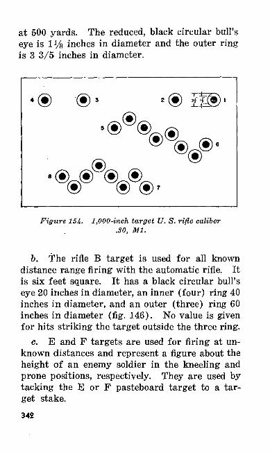
at 500 yards. The reduced, black circular bull's eye is 1% inches in diameter and the outer ring is 3 3/5 inches in diameter.
Figure 154. 1,000-inch target U. S. rifle caliber .30, Ml.
b. The rifle B target is used for all known distance range firing with the automatic rifle. It is six feet square. It has a black circular bull's eye 20 inches in diameter, an inner (four) ring 40 inches in diameter, and an outer (three) ring 60 inches in diameter (fig. 146). No value is given for hits striking the target outside the three ring.
c. E and F targets are used for firing at un known distances and represent a figure about the height of an enemy soldier in the kneeling and prone positions, respectively. They are used by tacking the E or F pasteboard target to a tar get stake.342

164. RANGESa. Ranges suitable for range firing with the
rifle caliber .30, Ml, are equally suitable for range firing with the automatic rifle.
6. The installation and construction of tar get ranges for small arms firing is governed by TM 9-855.
343
CHAPTER 4
MARKSMANSHIP, MOVING GROUND AND AERIAL TARGETS
Section I. GENERAL
165. INTRODUCTIONft. General. This chapter covers the funda
mentals of firing at moving targets. You will be trained to fire at moving men, vehicles, and ap propriate aerial targets within the effective range of the automatic rifle. Automatic rifle fire may be used against lightly armored vehicles and mo torized troops. It causes more heavily armored vehicles, like tanks, to button up, which restricts the vision of the crew.
b. Effective Range. Under normal condi tions, moving ground targets may be engaged ef fectively at ranges up to 400 yards. Effective re-
. suits beyond 400 yards are considered exceptional. Therefore, training in the technique of fire at moving ground, targets is normally limited to ranges up to 400 yards. Against parachutists and slow flying aircraft, the maximum effective range is 500 and 600 yards, respectively.
c. Battle Sights. Under combat conditions, moving targets are seldom exposed for long pe riods of time. You can also expect the targets to move quickly while they are exposed. Under344
these conditions, you may not have time to make sight settings. Therefore, instruction in the tech nique of firing at moving targets is based on the use of the battle sight and adjustment of the point of aim on the target.
166. WHEN TO CONDUCT TRAININGInstruction in the technique of firing at moving
targets follows instruction on known distance firing and precedes combat type firing. You will be trained to estimate the range and speed of mov ing vehicles before you practice firing at moving targets. Instruction in the technique of firing at aerial targets is limited to training in the aerial target firing position and in the leads to be taken for slow-moving aerial targets.
167. SAFETY PRECAUTIONSFor applicable safety precautions, see SR 385-
310-1; paragraphs 54, 161, and 231-235 of this manual; and local regulations.
Section II. MOVING PERSONNEL168. TECHNIQUE OF ENGAGING MOVING
TROOPSIn combat, moving enemy soldiers present
small, fast moving targets. This increases the importance of an accurate sight setting and an accurate lead. When targets appear suddenly, allowing no time for sight adjustment, you will have to use the battle sight and select a proper aiming point, with respect to the center of the tar get, so that the moving target and bullet meet.
345
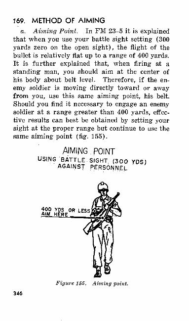
169. METHOD OF AIMINGa. Aiming Point. In FM 23-5 it is explained
that when you use your battle sight setting (300 yards zero on the open sight), the flight of the bullet is relatively flat up to a range of 400 yards. It is further explained that, when firing at a standing1 man, you should aim at the center of his body about belt level. Therefore, if the en emy soldier is moving directly toward or away from you, use this same aiming point, his belt. Should you find it necessary to engage an enemy soldier at a range greater than 400 yards, effec tive results can best be obtained by setting your sight at the proper range but continue to use the same aiming point (fig. 155).
AIMING POINTUSING BATTLE SIGHT (300 YDS)
AGAINST PERSONNEL
LESS
Figure 155. Aiming point.
346
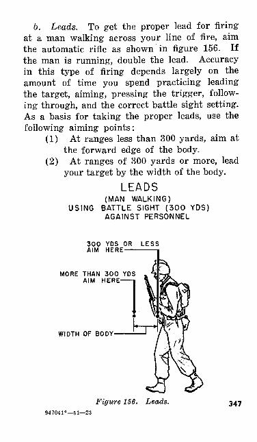
b. Leads. To get the proper lead for firing at a man walking across your line of fire, aim the automatic rifle as shown in figure 156. If the man is running, double the lead. Accuracy in this type of firing depends largely on the amount of time you spend practicing leading the target, aiming, pressing the trigger, follow ing through, and the correct battle sight setting. As a basis for taking the proper leads, use the following aiming points:
(1) At ranges less than 300 yards, aim at the forward edge of the body.
(2) At ranges of 300 yards or more, lead your target by the width of the body.
LEADS(MAN WALKING)
USING BATTLE SIGHT (300 YDS) AGAINST PERSONNEL
300 YDS OR AIM HERE —
LESS
MORE THAN 300 YDS AIM HERE-
WIDTH OF BODY
Figure 156. Leads. 347947041°—51—23
Section III. MOVING VEHICLES
170. HOW TO DETERMINE THE POINT OF AIM AND TO APPLY LEADS
a. The lead in terms of apparent target length necessary to hit a moving vehicle will depend on the size and speed of the vehicle and on its range. Vehicles moving across country rarely exceed a speed of 7 miles per hour. Vehicles moving on roads near the battle position will move much faster but as a general rule they will seldom be able to exceed a speed of 20 miles per hour.
b. Therefore, it is possible to establish a rule which will enable riflemen to hit most moving vehicles encountered on the battlefield.
(1) Normally, aim and fire at the leading edge of the target.
(2) If the speed of the target is greater than 15 miles per hour and the range is greater than 300 yards, aim and fire at a point one half the apparent length of the vehicle ahead of the target, (i/i length lead.)
c. Using the apparent target length in estab lishing the amount of lead makes it unnecessary to correct for the angle at which the target crosses the line of sight. For example, two identical ve hicles, A and B, are crossing your sector of fire. Each vehicle is at the same range and is traveling at the same speed. A is moving approximately straight across your front. B is crossing your front at an angle. As you look at the vehicles, A348
will appear to be moving faster. B will appear shorter and seem to be moving slower. Any ve hicle crossing your front at an angle will require less lead than a vehicle moving straight across your front. The correct amount of lead will be taken automatically when the apparent length of the target is used as a unit of measure.
171. TECHNIQUE OF ENGAGING MOVING VEHICLES
The following technique is suggested for firing at moving vehicles, using the battle sight:
a. For approaching or receding targets, hold your aim on the center of the target and press off each burst of shots.
b. For targets crossing your front at any angle, aline your sights on the front edge of the target; then swing the automatic rifle laterally in the direction the target is moving (if necessary, take and hold the estimated lead), and press off the burst. Swing the automatic rifle with a smooth, uniform motion.
c. Fire as rapidly as accurate aiming andleading will permit.
Section IV. AERIAL TARGETS
172. AIRCRAFT AND PARACHUTISTSa. A volume of rifle and automatic rifle
fire is effective against low flying troop carrier and slow flying observation aircraft, provided that shots are aimed well ahead of the target. Be-
349
cause of their speed, armor, and tactics, other types of aircraft are not considered suitable tar gets for rifle and automatic rifle fire.
b. Descending parachutists are also targets against which a volume of rifle and automatic rifle fire is effective. Remember that airborne troops are particularly vulnerable to collective small arms fire at the moment of landing and for a short period thereafter while they are securing their equipment and attempting to reorganize.
c. The maximum effective range of rifle and automatic rifle fire against slow moving aircraft is approximately 600 yards; against parachutists it is 500 yards.
173. TECHNIQUE OF ENGAGING AERIAL TARGETS
a. For aircraft targets descending directly to ward or climbing directly from your firing posi tion, aim directly at the target and press off your burst.
b. For aerial targets flying across your line of fire, rifle or automatic rifle fire, within its ef fective range, must be distributed along the path of flight and aimed ahead of the target so that the target and bullet will meet. When the range to the aircraft exceeds 400 yards, the automatic rifle should be aimed above as well as in front of the target. The unit of measure you will use to estimate the lead is the length of the target as it appears to you. A lead of two lengths is recom mended for slow flying observation planes, and a350
lead of one length is suggested for troop carrier aircraft. Aim at the feet of a descending para chutist at a range of 300 yards or less. At ranges over 300 yards lead him by one length.
c. After having completed a course of training in automatic rifle marksmanship and thereby ac quiring the fundamentals of good shooting, you need only to have practice in swing and follow through to enable you to fire on appropriate aerial targets. Steps to follow in firing at aerial targets are:
(1) Estimate the required lead, using the length of the target as a unit of measure.
(2) Aline the sights of the automatic rifle on the target, then rapidly swing ahead to the required lead.
(3) Swing the automatic rifle with a smooth, uniform motion to maintain the aim along the path of flight and at the required lead.
(4) Correctly press the trigger to fire the most rounds possible without disturbing the aim.
d. Infantrymen should be prepared to fire as soon as possible after receiving warning of the approach of hostile aircraft. You should begin tracking the target before it comes within effec tive range. This will enable you to track it smoothly and to fire the maximum number of rounds while it is within effective range.
351
CHAPTER 5
TECHNIQUE OF FIRE AND DESTRUCTION OF MATERIEL
Section I. TECHNIQUE OF FIRE
174. GENERALa. Technique of fire covers all the means used
to bring the collective fire of a fire unit on the tar get.
b. Collective fire is the combined and coordi nated fire by a group of men.
c. A fire unit is one whose fire in battle is under the direct control of a single leader. The usual unit of rifle and automatic rifle fire is the rifle squad.
175. IMPORTANCE OF EFFECTIVE COLLECTIVE FIRE
In battle, as in competitive sports, teamwork pays off. A good football team, or a good squad, is more than 11 or 9 well-trained individuals. It is a team that knows how to combine the strength and offensive power of its members and achieve a common goal. A rifle squad achieves its goals through combining and coordinating the fires of its rifles and automatic rifle, its grenades and other weapons, under the control of its leader.352
176. WHEN TECHNIQUE OF FIRE IS STUDIEDTraining in teamwork with the rifle and auto
matic rifle is taken up after both the riflemen and automatic rifle team members in your squad have learned how to care for and shoot their individual weapons. Because it is team training, you will all be trained together. The details of the train ing in technique of fire for both riflemen and auto matic riflemen are given in the Ml rifle manual, FM 23-5.
Section II. DESTRUCTION OF ORDINANCEMATERIEL IN EVENT OF IMMINENT
CAPTURE
177. GENERAL PRINCIPLESTactical situations may arise when, owing to
limitations of time or transportation, it becomes impossible to evacuate all equipment. In such situations, division or higher commanders may order the destruction of all materiel that cannot be evacuated to prevent its capture intact and its subsequent use by the enemy. When thorough destruction of all parts cannot be completed, de stroy those parts essential for using the automatic rifle. Ruin or remove the other parts that can not be duplicated easily by the enemy. Destroy the same .essential parts on all like units to pre vent the enemy from constructing one complete unit from the several damaged ones by consoli dating the serviceable parts. All units should be
353
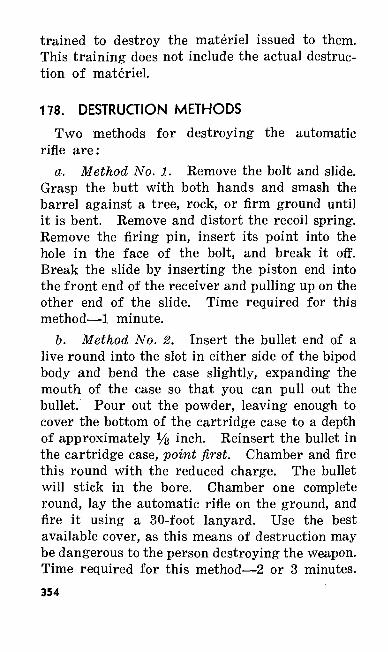
trained to destroy the materiel issued to them. This training does not include the actual destruc tion of materiel.
178. DESTRUCTION METHODSTwo methods for destroying the automatic
rifle are:a. Method No. 1. Remove the bolt and slide.
Grasp the butt with both hands and smash the barrel against a tree, rock, or firm ground until it is bent. Remove and distort the recoil spring. Remove the firing pin, insert its point into the hole in the face of the bolt, and break it off. Break the slide by inserting the piston end into the front end of the receiver and pulling up on the other end of the slide. Time required for this method—1 minute.
b. Method No. 2. Insert the bullet end of a live round into the slot in either side of the bipod body and bend the case slightly, expanding the mouth of the case so that you can pull out the bullet. Pour out the powder, leaving enough to cover the bottom of the cartridge case to a depth of approximately % inch. Reinsert the bullet in the cartridge case, point first. Chamber and fire this round with the reduced charge. The bullet will stick in the bore. Chamber one complete round, lay the automatic rifle on the ground, and fire it using a 30-foot lanyard. Use the best available cover, as this means of destruction may be dangerous to the person destroying the weapon. Time required for this method—2 or 3 minutes.354
Warning: Do not attempt to destroy the auto matic rifle by firing it with the muzzle stuck in the ground. This is dangerous and does not al ways destroy the weapon.
179. DESTRUCTION OF AMMUNITIONWhen time and materials are available, ammu
nition may be destroyed as follows. Break out all packed ammunition from boxes or cartons. Stack the ammunition in a pile. Stock or pile wood or available gasoline and oil in cans or drums around the ammunition. Throw onto the pile all available inflammable material such as scrap wood and brush. Pour any remaining gaso line or oil over the pile. Use enough inflam mable material to make a very hot fire. Ignite the materials and take cover. Thirty to sixty minutes are required to destroy the ammunition carried by small combat units.
355
CHAPTER 6
ADVICE TO INSTRUCTORS
Section I. GENERAL
180. PURPOSEThe purpose of this chapter is to assist you,
the instructor, in preparing and conducting auto matic rifle instruction. This chapter applies par ticularly to the training of large groups of auto matic riflemen in time of an emergency. The provisions of this chapter should be accepted as a guide only. Do not consider them as having the force of regulations.
181. SUBJECT SCHEDULESThe two subject schedules listed in this chapter
include a recommended breakdown of time for teaching a standard marksmanship course and for teaching a familiarization course. Both subject schedules include mechanical and preparatory marksmanship training and range firing with the automatic rifle. In addition to these subjects, the longer course includes transition firing and field target firing. The total time allotted for the standard course is 56 hours; for the familiariza tion course, 9 hours. For training purposes, an hour is considered to be 50 minutes for mechan ical and preparatory marksmanship training, and356
60 minutes for all range work. Use these sched ules as a guide in preparing lesson plans. Local conditions may require a longer or shorter period in which to complete the training. When the sug gested references, equipment, and training aids are not available, improvise or substitute the best that are available. All references in the subject schedules and subject schedule notes may be found in this manual unless otherwise indicated.
182. TRAINING NOTESTo supplement the two subject schedules given
in paragraphs 185 and 189 and to provide the de- ° tailed procedure to be followed for each period, training notes are included in paragraphs 186-188 and 190-192. During training, include demon strations with all lectures. Do not attempt to teach rapidly or slowly; teach at a speed that best enables the men to grasp clearly the material pre sented. Allot the majority of the training time to application of the principles brought out in the lectures and demonstrations. For practical work, organize the class into small groups and place an assistant instructor in charge of each group.
183. TRAINING PROGRAMa. To aid in the individual training phase, a
subject schedule for a course in BAR marksman ship training is shown in the paragraphs which follow. This schedule is based on the desirable number of hours to train each man quickly in the basic essentials so that he may be able to take
357
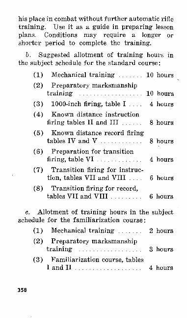
his place in combat without further automatic rifle training. Use it as a guide in preparing lesson plans. Conditions may require a longer or shorter period to complete the training.
b. Suggested allotment of training hours in the subject schedule for the standard course:
(1) Mechanical training ....... 10 hours(2) Preparatory marksmanship
training .................. 10 hours(3) 1000-inch firing, table I .... 4 hours(4) Known distance instruction
firing tables II and III ...... 8 hours(5) Known distance record firing
tables IV and V ............ 8 hours(6) Preparation for transition
firing, table VI ............. 4 hours(7) Transition firing for instruc
tion, tables VII and VIII .... 6 hours(8) Transition firing for record,
tables VII and VIII ......... 6 hours
c. Allotment of training hours in the subject schedule for the familiarization course:
(1) Mechanical training ....... 2 hours(2) Preparatory marksmanship
training .................. 3 hours(3) Familiarization course, tables
I and II ................... 4 hours
358
184. ASSISTANT INSTRUCTORSAn experienced and well-trained assistant in
structor is invaluable to both tne instructor and the class. Noncommissioned officers or selected privates are chosen to serve as assistant instruc tors. They must be well rehearsed before class time to become familiar with the subject matter. During the course of teaching, the instruction is often decentralized for periods of practical work under the direct supervision of the assistant in structors. Train them to demonstrate the exer cise while the exercise is being explained. Care fully rehearse the assistant instructors in the duties they are to perform so that when they pre sent a demonstration it is correct in every detail and is a clear picture of the work being explained.
359
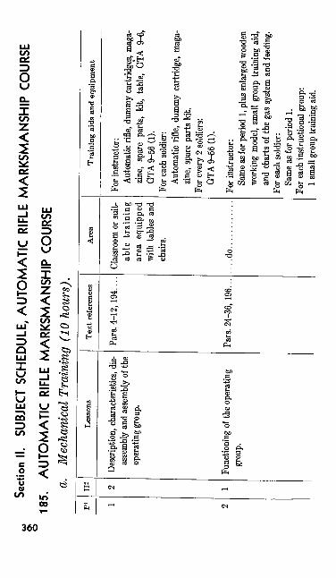
Secti
on II
. SU
BJEC
T SC
HEDU
LE, A
UTO
MA
TIC
RIF
LE M
AR
KSM
AN
SHIP
COU
RSE
185.
A
UTO
MA
TIC
RIF
LE M
AR
KSM
AN
SHIP
COU
RSE
a. M
echa
nica
l Tra
inin
g (1
0 ho
urs)
.pi 1 2
H2 2 1
Less
ons
Desc
riptio
n, c
hara
cteris
tics,
dis
asse
mbly
and
asse
mbly
of th
eop
erati
ng g
roup
.
Func
tioni
ng of
the
oper
ating
grou
p.
Tex
t ref
eren
ces
Pars
. 4-1
2, 19
4....
Pars.
24-
36, 1
96...
Are
a
Clas
sroom
or s
uit-
able
tra
inin
gar
ea e
quip
ped
with
tabl
es a
ndch
airs.
....do............
Tra
inin
g ai
ds a
nd e
quip
men
t
For i
nstru
ctor
:Au
tom
atic
rifle,
dum
my
cartr
idge
s, m
aga
zine,
spar
e pa
rts,
kit,
table,
GTA
9-6
,GT
A 9-
56 (1
).Fo
r eac
h so
ldier:
Auto
mati
c rif
le, d
ummy
cart
ridge
, mag
a zin
e, sp
are p
arts
kit.
For e
very
2 so
ldier
s:GT
A 9-
56 (1
).
For i
nstru
ctor
:Sa
me a
s (or
per
iod
1, pl
us en
large
d wo
oden
work
ing m
odel,
sma
ll gr
oup
train
ing
aid,
and
char
ts of
the
gas s
ystem
and
feed
ing.
For e
ach
sold
ier:
Sam
e as
for p
erio
d 1.
For e
ach
instr
uctio
nal g
roup
:1 s
mall
gro
up tr
ainin
g aid
.
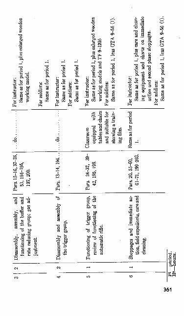
and
func
tioni
ng o
f the
buf
fer a
nd
rate
red
ucin
g gr
oup;
gas
ad
justm
ent.
Disa
ssem
bly
and
asse
mbl
y of
the
trigg
er g
roup
.
Func
tioni
ng o
f tri
gger
gro
up,
revi
ew o
f fu
nctio
ning
of
the
auto
mat
ic ri
fle.
Stop
page
s an
d im
med
iate
ac
tion,
field
expe
dien
ts, c
are a
nd
clean
ing.
Pars.
15-
16,3
7-38
, 53
, 194
-195
, 19
7, 20
0.
Pars.
13-
14, 1
94.
Pars.
24
-37,
39-
42, 1
95, 1
98.
Pars.
20,
55-6
0, 61
-71,
199-
203.
.do............
..do.
.
Clas
sroom
eq
uipp
ed
with
tab
les an
d ch
airs
and
suita
ble
for
show
ing a
train
in
g fil
m.
Sam
e as f
or p
erio
d 1.
For i
nstru
ctor:
Sam
e as f
or p
erio
d 1,
plus
enlar
ged
wood
en
work
ing
mode
l.
For s
oldi
ers:
Sam
e as
for p
erio
d 1.
For i
nstru
ctor
:Sa
me
as fo
r per
iod
1. Fo
r sol
dier
s:Sa
me as
for p
eriod
1.
For i
nstru
ctor:
Same
as fo
r peri
od 1,
plus
enlar
ged w
oode
n wo
rking
mod
els an
d TF
9-12
05Fo
r sold
iers:
Same
as f
or p
eriod
1, l
ess G
TA 9
-56
(1).
For i
nstru
ctor:
Same
as f
or p
eriod
1, p
lus c
are a
nd c
lean
ing e
quip
men
t and
cha
rts o
n im
med
iate
actio
n an
d se
cond
pha
se st
oppa
ges.
For s
oldier
s: Sa
me a
s fo
r peri
od 1
, les
s GTA
9-5
6 (1
).P
i-pe
riod
. H
Z—ho
urs.
IX)
0>
topi 7
H2 1
Less
ons
Revie
w of
all m
ateria
l cov
ered
in pr
eced
ing s
ix pe
riods
fol
lowed
by
an e
xam
inati
on.
Tex
t re
fere
nces
All p
revi
ous
refere
nces
.
Are
a
Sam
e as
for p
erio
d1.
Tra
inin
g ai
ds a
nd e
quip
men
t
For i
nstru
ctor
:Al
l tra
inin
g aid
s an
d eq
uipm
ent u
sed fo
rpr
eced
ing
perio
ds, l
ess
TF 9
-120
5. .
For s
oldi
ers:
Sam
e as
for p
erio
d 1.
b. Pr
epar
ator
y M
arks
man
ship
Tr
aini
ng
(10
hour
s)
Intro
ducti
on
to pr
epar
atory
ma
rksm
ansh
ip—sig
hting
and
aim
ing ex
ercise
s.
Pars.
87-
95,
205,
210.
1,000
-inch
ran
ge
or oth
er tra
in
ing ar
ea su
itable
fo
r pr
epar
atory
m
arks
man
ship
tra
inin
g.
For i
nstru
ctor:
Auto
mati
c rifl
e, au
tom
atic r
ifle b
elt, s
ight
ing a
nd a
iming
bar,
aim
ing s
take,
auto
ma
tic ri
fle re
st (bo
x), M
l 5 si
ghtin
g de
vice,
box
with
shee
t of
white
pap
er a
ttach
ed,
bull's
eye
disk
, pe
ncil,
spar
e pa
rts b
ox,
prog
ress
char
ts, s
ight
black
ening
equ
ip m
ent,
sight
pict
ure
mode
l, fir
st aid
box
," pu
blic a
ddres
s sys
tem (i
f ava
ilable
), an
d a
table.
Prep
arat
ory
mar
ksm
ansh
ip -
posit
ion
exer
cises
.Pa
rs. 9
6-11
5, 2
11.
...do
.
For e
very
4 so
ldier
s:A
utom
atic
rifle
, aut
omat
ic ri
fle b
elt,
sight
in
g an
d aim
ing
bar,
auto
mat
ic r
ifle
rest,
bo
x w
ith s
heet
of
whi
te p
aper
atta
ched
, bu
ll's
eye
disk
, pe
ncil,
and
M15
sig
htin
g de
vice
.Fo
r eve
ry 1
2 so
ldier
s: Si
ght b
lack
enin
g eq
uipm
ent.
For i
nstru
ctor
:A
utom
atic
rifle
, aut
omat
ic ri
fle b
elt,
aim
in
g sta
ke,
tabl
e, s
pare
par
ts b
ox,
sight
bl
acke
ning
eq
uipm
ent,
first
aid
box,
prog
ress
cha
rts,
publ
ic ad
dres
s sy
stem
(if
avai
labl
e).
For e
very
2 so
ldier
s: A
utom
atic
rifl
e, au
tom
atic
rifl
e be
lt.Fo
r eve
ry 1
2 so
ldier
s: Ai
min
g sta
ke a
nd s
ight
bla
cken
ing
equi
p m
ent.
PI—
peri
od.
H2—
hour
s.
pi 10 11
H2 1 2
Less
ons
Prep
arat
ory
mar
ksm
ansh
ip —
sight
sett
ing
and
trigg
er m
a ni
pulat
ion
exerc
ises.
Prep
arat
ory
mar
ksm
ansh
ip —
auto
mat
ic fi
re ex
ercise
s. '
Tex
t ref
eren
ces
Pars.
116
-121
,21
2.
Pars
. 122
-124
,21
3.
Are
a
1,000
-inch
ran
geor
othe
r tra
in
ing ar
ea su
itabl
efo
r pr
epar
atory
mar
ksm
ansh
iptra
inin
g.
....do............
Tra
inin
g ai
ds a
nd e
quip
men
t •
For i
nstru
ctor
:Au
tomati
c rifl
e, au
tom
atic r
ifle b
elt, m
aga
zine,
char
ts on
trig
ger
man
ipul
ation
and
rear
sigh
t, 1,0
00-in
ch t
arge
t U.
S.
rifle
calib
er .30
, Ml,
table,
first
aid
box,
spare
parts
box
, sig
ht b
lacke
ning
equ
ipm
ent,
prog
ress c
harts
, and
a p
ublic
add
ress s
ys
tem (i
f ava
ilable
).Fo
r eve
ry 2
soldi
ers:
Auto
mati
c rifl
e, au
tom
atic r
ifle b
elt, m
aga
zine.
For e
very
4 so
ldier
s:1,0
00-in
ch ta
rget
U. S
. rifl
e cali
ber .
30 M
l.
For i
nstru
ctor:
Sam
e as
for
per
iod
10, p
lus
1 m
agaz
ine.
For e
very
2 so
ldiers
:Sa
me
as fo
r peii
od 1
0, pl
us 1
mag
azin
e.
12 13
2 1
Prep
arat
ory
mar
ksm
ansh
ip —
sight
cha
nges
, ef
fect
of
the
wind
, sc
ore
card
, ra
nge
pro
cedu
re, s
afet
y pr
ecau
tions
.
Exam
inati
on...
...
....
....
....
Pars
. 126
-132
,14
6, 21
4.
All p
reviou
s refe
r en
ces a
nd p
ara.
133,
215.
....
do
....
....
....
....
do
....
....
....
For i
nstru
ctor
:En
larg
ed c
harts
of
sight
cha
nges
, sc
ore
card
an
d clo
ck
syste
m;
penc
il;
tabl
e;bl
ackb
oard
with
cha
lk a
nd e
rase
r; pr
ogre
ssch
arts;
pub
lic a
ddre
ss s
yste
m (
if av
ail
able.
For e
ach
sold
ier:
Penc
il, s
core
car
d.
For i
nstru
ctor
:Si
ghtin
g an
d aim
ing d
evice
, 8 a
utom
atic
rifles
, 9 a
utom
atic
rifle
bel
ts, 2
tabl
es, s
ight
pictu
re d
evice
, 4 a
iming
stak
es, 4
1,00
0-inc
h tar
gets
U. S
. rifl
e cali
ber .
30 M
l, an
d1
chair
.Fo
r eac
h so
ldier:
None
.
P' —
perio
d.H2
— ho
urs.
o Ul
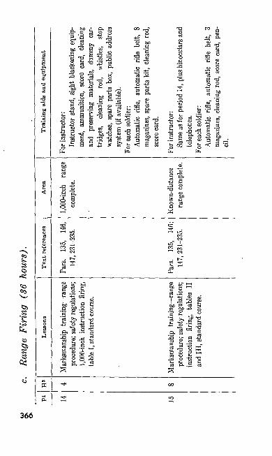
c. Ra
nge
Fir
ing
(86
hour
s).
Pi 14 15
H2 4 8
Less
ons
Mar
ksrc
ansh
ip t
rain
ing —
range
proc
edur
e; sa
fety
regu
lation
s;1,0
00-in
ch i
nstru
ction
firi
ng,
tabl
e I,
stan
dard
cou
rse.
Mar
ksm
ansh
ip t
rain
ing —
rang
epr
oced
ure;
saf
ety
regu
latio
ns;
instr
uctio
n fir
ing,
tables
II
and
III, s
tanda
rd co
urse
.
Tex
t ref
eren
ces
Pars.
13
5, 14
6,14
7, 23
1-23
5.
Pars.
13
5, 14
6;14
7, 23
1-23
5.
Are
a
1,000
-inch
ran
geco
mplet
e.
Kno
wn-
dista
nce
rang
e co
mpl
ete.
Tra
inin
g ai
ds a
nd e
quip
men
t
For i
nstru
ctor:
Instr
ucto
r stan
d, sig
ht bla
cken
ing e
quip
ment,
amm
uniti
on,
scor
e ca
rd,
clean
ingan
d pr
eserv
ing m
ateria
ls, d
ummy
car
tridg
es,
clea
ning
ro
d,
whist
les,
stop
watch
es, s
pare
par
ts bo
x, pu
blic
addr
ess
syste
m (i
f ava
ilabl
e).
For e
ach
sold
ier:
Auto
mati
c rif
le, a
utom
atic
rifle
belt,
8m
agaz
ines
, sp
are
parts
kit,
cle
anin
g ro
d,sc
ore c
ard.
For i
nstru
ctor
:Sa
me as
for p
erio
d 14
, plus
bino
cular
s and
telep
hone
s.Fo
r eac
h so
ldier:
Aut
omat
ic r
ifle,
auto
mat
ic r
ifle
belt,
3
mag
azin
es,
clean
ing
rod,
sco
re c
ard,
pen
cil
.
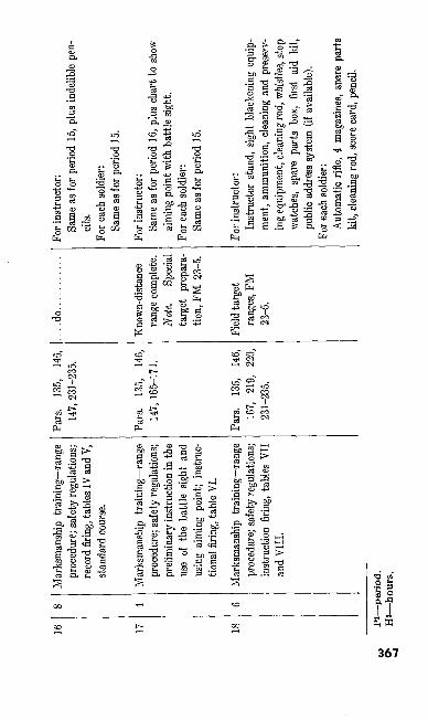
16 18
Mar
ksm
ansh
ip t
rain
ing—
rang
e pr
oced
ure;
saf
ety
regu
latio
ns;
reco
rd fi
ring,
tabl
es IV
and
V,
stand
ard
cour
se.
Mar
ksm
ansh
ip t
rain
ing—
rang
e pr
oced
ure;
saf
ety
regu
latio
ns;
prel
imin
ary
instr
uctio
n in
the
use
of t
he b
attle
sig
ht a
nd
usin
g ai
min
g po
int;
instr
uc
tiona
l firi
ng, t
able
VI.
Mar
ksm
ansh
ip t
rain
ing—
rang
e pr
oced
ure;
saf
ety
regu
latio
ns;
instr
uctio
n fir
ing,
tabl
es V
II
and
VII
I.
Pars
. 13
5, 14
6,14
7, 23
1-23
5.
Pars
. 13
5, 14
6,14
7, 16
5-17
1.
Pars
. 13
5, 14
6,16
7, 21
9, 22
0,23
1-23
5.
....do............
Kno
wn-
dista
nce
rang
e co
mpl
ete.
Note,
Sp
ecial
targ
et p
repa
ra
tion,
FM
23-
5.
Fiel
d ta
rget
rang
es, F
M23
-5.
For i
nstru
ctor
:Sa
me a
s for
peri
od 1
5, plu
s ind
elible
pen
cil
s.Fo
r eac
h so
ldier:
Sa
me as
for p
eriod
15.
For i
nstru
ctor
:Sa
me
as fo
r pe
riod
16, p
lus
char
t to
show
aim
ing
poin
t with
bat
tle si
ght.
For e
ach
sold
ier:
Sam
e as f
or p
eriod
15.
For i
nstru
ctor
:In
stru
ctor
sta
nd,
sight
bla
cken
ing
equi
p m
ent,
amm
uniti
on,
clea
ning
and
pre
serv
in
g eq
uipm
ent,
clea
ning
rod,
whi
stles
, sto
p w
atch
es,
spar
e pa
rts b
ox,
first
aid
kit,
publ
ic a
ddre
ss s
yste
m (
if av
aila
ble)
.Fo
r eac
h so
ldier:
Auto
mati
c rif
le, 4
mag
azine
s, sn
are p
arts
kit,
clean
ing ro
d, sc
ore c
ard, p
encil
.
^
PI—
perio
d.
O>
H2—
hour
s.
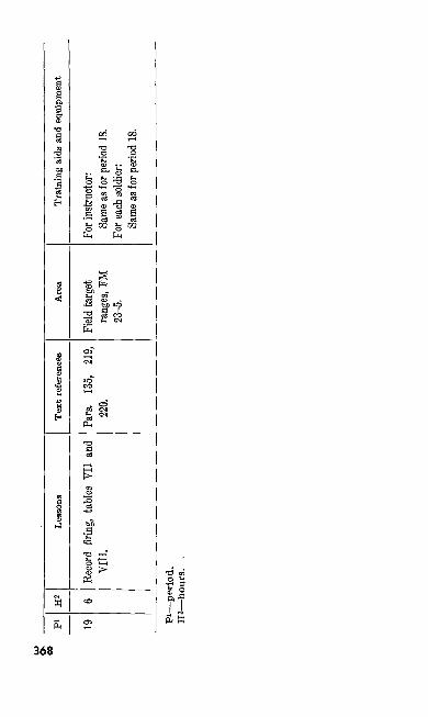
pi 19
H* 6
Less
ons
Reco
rd f
iring
, tab
les V
II an
dVI
II.
Text
refe
renc
es
Pars.
13
5, 21
9,22
0.
Are
a
Field
targ
etran
ges,
FM23
-5.
Trai
ning
aid
s an
d eq
uipm
ent
For i
nstru
ctor:
Sam
e as f
or p
erio
d 18
.Fo
r eac
h so
ldier:
Same
as fo
r peri
od 1
8.
Pi—
peri
od.
H2—
hour
s.
.
186. TRAINING NOTES, MECHANICAL TRAIN ING-10 HOURS
a. General.(1) Mechanical training is best given by
organizing the class into small groups, not to exceed six men, with an assistant instructor in charge of each group. If there are not enough assistant instruc tors to organize the class in this way, seat the groups so that the assistant in structors can move freely among the sol diers.
(2) Enlarged charts and wooden working models facilitate this training. For a detailed discussion of recommended training aids, see paragraphs 223-230.
(3) Teach nomenclature concurrently dur ing mechanical training.
(4) Emphasize and closely supervise prac tical work.
(5) Before each period—(a) Completely orient and rehearse all
assistant instructors and demonstra tors.
(&) Install all instruction material.(6) For a detailed discussion of recom
mended methods for conducting mechan ical training with the automatic rifle, see paragraphs 193-204.
369
b. First Period (2 hrs.).(1) The purpose of this lesson is to teach
the disassembly and assembly of the operating group and the characteristics and description of the automatic rifle.
(2) Introduce mechanical training to in clude the characteristics and a descrip tion of the automatic rifle (pars. 4, 5, and 193 (15 min.).
(3) Explain, demonstrate, and supervise practical work on the disassembly of the operating group (pars. 11 and 194) (45 min.).
(4) Explain, demonstrate, and supervise practical work on the assembly of the operating group (pars. 12 and 194) (40 min.).
c. Second Period (1 hr.).(1) The purpose of this lesson is to teach
the functioning of the operating group.(2) Explain the functioning of the operat
ing group during the rearward move ment (pars. 24-31 and 196)(30 min.).
(3) Explain the functioning of the opera- ing group during the forward movement (pars. 24-36 and 196) (20 min.).
d. Third Period (2 hrs.).(1) The purpose of this lesson is to teach
the disassembly and assembly of the buf fer and rate reducing group, the func-
370
tioning of the buffer mechanism, and gas adjustment.
(2) Explain, demonstrate, and supervise practical work on the disassembly of the buffer and rate reducing group (pars. 15 and 194) (30 min.).
(3) Explain the functioning of the buffer portion of the buffer and rate reducing group (pars. 38 and 197) (20 min.).
(4) Explain, demonstrate, and supervise practical work on the assembly of the buffer and rate reducing group (pars. 16 and 194) (SO min.).
(5) Explain and supervise practical work on gas adjustment (pars. 53 and 200) (20 min.).
e. Fourth Period (2 hrs.).(1) The purpose of this lesson is to teach
the disassembly and assembly of the trigger 'group.
(2) Explain, demonstrate, and supervise practical work on the disassembly of the trigger group (pars. 13 and 194) (50 min.).
(3) Explain, demonstrate, and supervise practical work on the assembly of the trigger group (pars. 14 and 194) (50 min.).
f. Fifth Period (1 hr.).(1) The purpose of this lesson is to teach
the functioning of the trigger group and
371
the rate reducing portion of the buffer and rate reducing group as well as to review all functioning taught in the pre ceding periods.
(2) Explain the functioning of the trigger group and the rate reducing portion of the buffer and rate reducing group (pars. 39-42 and 198 (SO min.)
(3) Review all functioning covered in the preceding periods by showing TF 9- 1205 (20 min.).
g. Sixth Period (1 hr.).(1) The purpose of this lesson is to teach
stoppages, immediate action, field ex pedients, and care and cleaning of the automatic rifle.
(2) Introduce and explain stoppages (pars. 55, 56, and 202) (10 min.).
(3) Explain, demonstrate, and supervise practical work on immediate action (pars. 57-59 and 201) (10 min.).
(4) Explain, demonstrate, and supervise practical work on the second phase stoppages (pars. 60 and 202) (10 min.).
(5) Explain, demonstrate, and supervise practical'work on field expedients (pars. 20 and 199) (10 min.).
(6) Explain and demonstrate care and cleaning (pars. 63-fifi and 203) (10 min.).
372
h. Seventh Period (1 hr.).(1) In this period give an examination to
determine if the men have retained the instructional material covered during mechanical training.
(2) Explain the procedures to be followed in the examination (par. 133) (5 min.).
(3) Give the examination, including ques tions over all material covered during the preceding six periods (40 min.).
(4) Critique the examination. Answer all examination questions as well as any questions that members of the class may ask (par. 133) (5 min.).
187. TRAINING NOTES, PREPARATORY MARKS MANSHIP—10 HOURS
a. General.(1) Preparatory marksmanship training is
best given by organizing the class into four-man groups with an assistant in structor in charge of every two or three groups. The quality of the instruction varies with the amount of trained super vision. When the ratio of one assistant instructor for each two groups cannot be met, make every effort to keep the ratio as small as possible. In organiz ing the group, attempt to place an in experienced soldier with one who is fa miliar with the automatic rifle.
373
(2) Use the coach and pupil method of in struction whenever possible.
(3) Enlarged charts and other training aids facilitate this training. For a detailed discussion of training aids used during preparatory marksmanship, see para graphs 223-230.
(4) Emphasize and closely supervise prac tical work. Follow each short confer-^ ence period with practical work.
(5) Before each period:(a) Completely rehearse and orient all
assistant instructors and demonstra- .tors.
(6) Install all instruction material.(c) Organize the class into four-man
groups and announce these groups at least the day before preparatory marksmanship training is conducted. This action will help avoid confusion and loss of time during preparatory marksmanship training.
(6) For a detailed explanation of recom mended methods for conducting instruc tion in preparatory marksmanship train ing with the automatic rifle, see para graphs 86, 88, and 205-209.
b. Eighth Period (2 hrs.).(1) The purpose of this lesson is to intro
duce preparatory marksmanship and to teach correct sight alinement, correct
374
sight picture, and the three sighting and aiming exercises.
(2) Introduce preparatory marksmanship (pars. 85-88 and 205) (10 min.).
(3) Explain and demonstrate correct sight alinement, correct sight picture, and the three sighting and aiming exercises (pars. 90, 91, 93-95, and 210) (20 min.).
(4) Conduct and supervise practical work on the first sighting and aiming exer cise (20 min.).
(5) Conduct and supervise practical work on the second sighting and aiming exer cise (20 min.).
(6) Conduct and supervise practical work on the third sighting and aiming exer cise. (30 min.).
c. Ninth Period (2 hrs.).(1) The purpose of this lesson is to teach
automatic rifle positions.
(2) Review all pertinent instruction ma terial covered in the previous period. (10 min.).
(3) Explain and demonstrate the prone, sitting, kneeling, crouch, and aerial tar get positions with the automatic rifle (pars. 106-115 and 211) (20 min.).
(4) Conduct and supervise practical work on the prone position with the automatic rifle (20 min.).
375
(5) Conduct and supervise practical work in the adjustments of the loop and hasty slings (pars. 98-101) (Wmin.).
(6) Conduct and supervise practical work on the sitting position with the automatic rifle (15 min.).
(7) Conduct and supervise practical work on the kneeling position with the auto matic rifle (15 min.).
(8) Conduct and supervise practical work on the crouch position and the special sling adjustment for the crouch position (10 min.).
d. Tenth Period (1 hr.).(1) The purpose of this lesson is to teach
sight setting and trigger manipulation exercises with the automatic rifle.
(2) Review all pertinent material covered in the previous periods (10 min.).
(3) Explain and demonstrate sight setting and trigger manipulation exercises to in clude sight setting exercises, trigger ma nipulation exercises, and a timed exer cise combining the first two exercises (pars. 119-121 and 202) (15 min.).
(4) Conduct and supervise practical work on sight setting and trigger manipula tion exercises (25 min.).
e. Eleventh Period (2 hrs.).(1) The purpose of this lesson is to teach
automatic fire exercises with the auto matic rifle.
376
(2) Review all pertinent material covered in the previous periods (10 min.).
(3) Explain and demonstrate the correct method for placing magazines in the belt and the automatic fire exercises (pars. 122-124 and 213) (20 min.).
(4) Conduct and supervise practical work on the correct method of placing maga zines in the automatic rifle belt (10 min.).
(5) Conduct and supervise practical work on loading the initial magazine, chang ing magazines, and clearing the auto matic rifle (25 min.).
(6) Conduct and supervise practical work on the three and eight magazine auto matic fire exercises (35 min.).
f. Twelfth Period (2 hrs.).(1) The purpose of this lesson is to teach
sight changes, effect of the wind, zero ing, use of the score card, range proce dures, and safety precautions.
(2) Review all pertinent material covered in the previous periods (10 min.).
(3) Explain and demonstrate sight changes (pars. 126 and 214) (30 min.).
(4) Explain and demonstrate the methods for determining the velocity of the wind, the effect of the wind, and the wind formula (pars. 129 and 214) (15 min.).
377
(5) Explain and demonstrate the use of the score card (pars. 131 and 132) (10 min.).
(6) Explain and demonstrate the correct procedure for zeroing and using the score card (pars. 130 and 132) (15 min.).
(7) Explain range procedures and safety precautions (pars. 146, 147, and 231- 235) (20 min.).
g. Thirteenth Period (1 hr.).(1) In this period give an examination to
determine if the men have retained the material covered during preparatory marksmanship training.
(2) Explain the procedures to be followed in the examination (par. 215) (5 min.).
(3) Give the examination, including ques tions over all material covered during the preceding six periods (par. 133) (45 min.).
188. TRAINING NOTES, RANGE FIRING—36 HOURS
a. General.(1) Range firing training is best given by
organizing the class into three orders per firing point for instruction firing and four orders per firing point for rec ord firing. These figures may be varied to comply with range facilities and the number of available weapons. If enough
378
trained men are available, one assistant instructor should be assigned to each firing point to serve as a coach. How ever, if this is not possible, assign one trained man to every four or five firing points. Insofar as possible, assistant instructors should be assigned to the same students that they supervised dur ing preparatory marksmanship training.
(2) Use the coach and pupil method of in struction on firing points where experi enced assistant instructors are not avail able to act as coaches.
(3) Before each period—(a) Completely orient all assistant in
structors. (6) Install all instruction material.(c) Clear with the installation range of
ficer if one is assigned; otherwise, clear with the designated unit range officer for the use of the range and range equipment.
(d) Check pertinent safety precautions and regulations to include those pecu liar to the range to be used.
(e) Organize the class into three or four man groups and announce these groups at least the day before firing is conducted. This action will help avoid confusion and loss of time on the range. Whenever possible, use the
947041°—51—25379
group assignments that were made during preparatory marksmanship training.
(4) For a detailed discussion of recom mended methods for conducting instruc tion in range firing with the automatic rifle see paragraphs 153-155.
b. Fourteenth Period (4 hrs.).(1) The purposes of this lesson are—
(a) To continue the instruction pre sented during preparatory marksman ship training through firing exercises on the 1000-inch range.
(b) To give the soldier an opportunity to acquaint himself with the automatic rifle before firing on the known dis tance range.
(2) Review range procedures and safety precautions (pars. 146, 147, and 231- 235) (10 min.).
(3) Conduct and supervise the instruction firing of table I of the standard course (pars. 135 and 155) (230 min.).
c. Fifteenth Period (8 hrs.).(1) The purpose of this lesson is to permit
the soldier to obtain and verify the zero of his automatic rifle and to familiarize himself with known distance firing pro cedures. This prepares him for the qualification course.
380
(2) Explain the importance of marksman ship training and discuss the course to be fired as well as the regulations gov erning instruction firing (pars. 135,143- 150, and 216) (10 min.).
(3) Review range procedures and safety precautions (pars. 146, 147, and 231- 235) (10 min.).
(4) Conduct and supervise the instruction firing of tables II and III of the stand ard course (pars. 135, 148, 153, and 154) (460 min.).
d. Sixteenth Period (8 hrs.).(1) The purpose of this lesson is to deter
mine the soldier's ability to fire the auto matic rifle and to provide him an op portunity to fire the known distance por tion of the record course.
(2) Discuss the record course and regula tions for record firing (pars. 135 and 156) (10 min.).
(3) Review range procedures and safety precautions (pars. 146, 147, and 231- 235) (10 min.).
(4) Conduct and supervise the record fir ing of tables IV and V of the standard course (pars. 135, 153, and 154) (460 min.).
e. Seventeenth Period (4 hrs.).(1) The purpose of this lesson is to give
training in the use of the battle sight381

and aiming point and the method of en gaging field type (silhouette) targets.
(2) Discuss the theory and use of the battle sight in the application of fire on targets within 400 yards (pars. 117, 165, 169, and 217) (20 min.).
(3) Review range procedure and safety precautions (pars. 146, 147, and 231- 235) (10 min.).
(4) Conduct the firing of table VI of the standard course in preparation for transition firing (pars. 135, 218, and FM 23-5) (210 min.).
f. Eighteenth Period (6 hrs.).(1) The purpose of this lesson is to permit
the soldier to practice the use of the bat tle sight and aiming point and to fa miliarize himself with the transition course.
(2) Review the theory and use of the battle sight and the method of engaging field type (silhouette) targets (pars. 165- 169) (10 min.).
(3) Review range procedures and safety precautions (pars. 146, 147, and 231- 235) (10 min.).
(4) Conduct and supervise the instruction firing of tables VII and VIII of the standard course (pars. 135, 219, and FM 23-5) (340 min.).
382

g. Nineteenth Period (6 hrs.).(1) The purpose of this lesson is to provide
the soldier an opportunity to fire the transition portion of the record course.
(2) Review range procedures and safety precautions (pars. 146, 147, and 231- 235) (10 mm.;.
(3) Conduct and supervise the firing of tables VII and VIII of the standard course for record (350 min.).
383
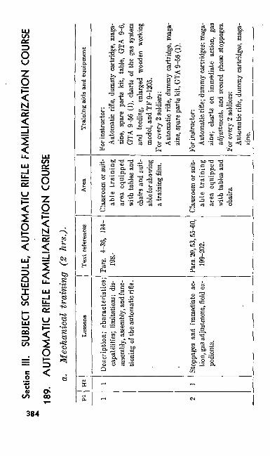
00Se
ction
III.
SUBJ
ECT
SCHE
DULE
, AU
TOM
ATIC
RIFL
E FA
MIL
IAR
IZA
TIO
N C
OURS
E
189.
AU
TOM
ATIC
RIFL
E FA
MIL
IAR
IZA
TIO
N C
OURS
Ea.
Mec
hani
cal
trai
ning
(2
hrs,
).
pi 1 2
H2 1 !
Less
ons
Des
crip
tion;
cha
ract
eris
tics;
capa
bilit
ies;
limita
tions
; di
s as
sem
bly,
asse
mbl
y, an
d fu
nc
tioni
ng o
f the
aut
omat
ic ri
fle.
Stop
page
s an
d im
med
iate
ac--
tion,
gas
adju
stmen
t, fie
ld ex
pe
dien
ts.
Tex
t ref
eren
ces
Pars.
4-
36,
194-
198.-
Pars.
20,5
3,55
-60,
199-
202.
Are
a
Clas
sroom
or s
uit
able
tra
inin
gar
ea e
quip
ped
with
tabl
es a
ndch
airs
and
suit
able
for s
howi
nga t
rain
ing
film.
Clas
sroom
or s
uit
able
tra
inin
gar
ea e
quip
ped
with
tabl
es a
ndch
airs.
Tra
inin
g ai
ds a
nd e
quip
men
t
For i
nstru
ctor:
Aut
omat
ic ri
fle, d
umm
y ca
rtrid
ge, m
aga
zine,
spar
e pa
rts k
it, t
able,
GTA
9-6
,GT
A 9-
56 (
1), c
harts
of
the
gas
syste
man
d fee
ding,
enlar
ged
wood
en w
orkin
gmo
del,
and
TF 9
-120
5.Fo
r eve
ry 2
sold
iers:
Aut
omat
ic ri
fle, d
umm
y ca
rtrid
ge, m
aga
zine,
spar
e par
ts ki
t, GT
A 9-
56 (1
).
For i
nstru
ctor
:A
utom
atic
rifle
; dum
my
cartr
idge
s; m
aga
zine;
char
ts on
im
med
iate
actio
n, ga
sad
justm
ent,
and
seco
nd p
hase
sto
ppag
es.
For e
very
2 so
ldier
s:A
utom
atic
rifle
, dum
my
cartr
idge
s, m
aga
zine.
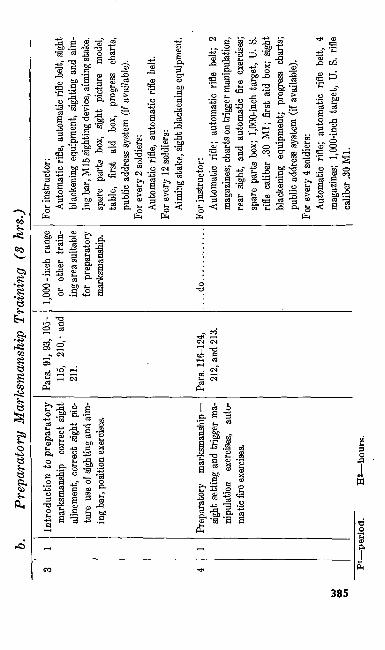
b. Pr
epar
ator
y M
arks
man
ship
Tra
inin
g (3
hrs
.)
4 ,
1
Intro
duct
ion
to p
repa
rato
ry
mar
ksm
ansh
ip—
corre
ct sig
ht
aline
men
t, co
rrect
sight
pic
ture
use
of s
ight
ing
and
aim
ing
bar,
posit
ion
exerc
ises.
Prep
arat
ory
mar
ksm
ansh
ip —
sig
ht s
ettin
g an
d tri
gger
ma
nipu
latio
n ex
ercise
s, au
to
mat
ic fi
re ex
ercise
s.
Pars
. 91,
93, 1
05-
115,
210,-
and
21
1.
Pars
. 116
-124
, 21
2, an
d 21
3.
1,00
0-in
ch r
ange
or
oth
er t
rain
in
g are
a sui
table
for
prep
arat
ory
mar
ksm
ansh
ip.
.do.
For i
nstru
ctor
:A
utom
atic
rifle
, aut
omat
ic ri
fle b
elt, s
ight
bl
acke
ning
equ
ipm
ent,
sight
ing
and
aim
ing
bar,
M15
sigh
ting
devic
e, aim
ing s
take,
spar
e pa
rts b
ox,
sight
pict
ure
mode
l, ta
ble,
first
aid
box,
prog
ress
ch
arts,
pu
blic
addr
ess
syste
m (
if av
aiiab
le).
For e
very
2 so
ldier
s: A
utom
atic
rifl
e, au
tom
atic
rifl
e be
lt.Fo
r eve
ry 1
2 sol
dier
s: Ai
min
g sta
ke, s
ight
blac
keni
ng e
quip
men
t.
For i
nstru
ctor
:A
utom
atic
rifl
e; au
tom
atic
rifl
e be
lt; 2
m
agaz
ines
; cha
rts on
trig
ger m
anip
ulati
on,
rear
sig
ht,
and
auto
mat
ic f
ire e
.xerci
ses;
spar
e pa
rts b
ox;
1,000
-inch
tar
get,
U. S
. rif
le ca
liber
.30
Ml;
first
aid b
ox;
sight
bl
acke
ning
equ
ipm
ent;
prog
ress
cha
rts;
publ
ic ad
dres
s sy
stem
(if a
vaila
ble)
.Fo
r eve
ry 4
sold
iers:
Auto
mati
c rif
le; a
utom
atic
rifl
e be
lt, 4
m
agaz
ines
; 1,0
00-in
ch t
arge
t, U.
S.
rifle
calib
er .3
0 M
l.PI
—pe
riod
.H
2—ho
urs.
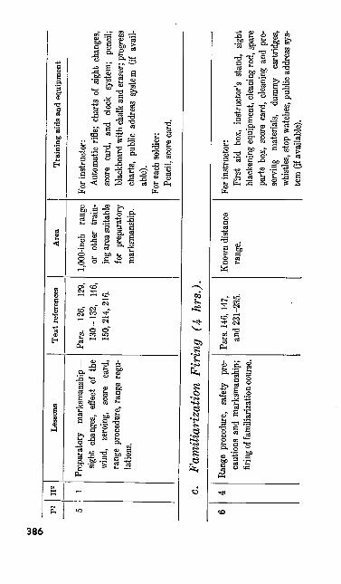
b)
00
pi 5
H2 1
Less
ons
Prep
arat
ory
mar
ksm
ansh
ip —
sight
cha
nges
, ef
fect
of t
hewi
nd,
zero
ing,
scor
e ca
rd,
range
pro
cedu
re, ra
nge
regu
lation
s.
Text
refe
renc
es
Pars
. 12
6, 12
9,13
0-13
2,
146,
150,
214,
216.
Are
a
1,00
0-in
ch
rang
eor
oth
er t
rain
ing
area
suita
blefo
r pr
epar
ator
yma
rksm
ansh
ip.
Trai
ning
aid
s an
d eq
uipm
ent
For i
nstru
ctor
:Au
tomati
c rif
le; c
harts
of s
ight
chan
ges,
scor
e ca
rd,
and
clock
sys
tem;
penc
il;bl
ackb
oard
with
cha
lk an
d er
aser
; pro
gres
sch
arts,
publi
c ad
dres
s sy
stem
(if
avail
ab
le).
For e
ach
sold
ier:
Penc
il, sc
ore
card
.
c. Fa
mili
ariz
atio
n Fi
ring
(4
hrs.
).
Rang
e pr
oced
ure,
safet
y pr
e ca
ution
s an
d ma
rksm
ansh
ip;
firing
of fa
milia
rizati
on co
urse
.
Pars.
146
, 147
, an
d 23
1-23
5.Kn
own
distan
ce
range
.Fo
r ins
tructo
r:Fi
rst a
id bo
x, in
struc
tor's
stan
d, sig
ht bla
cken
ing e
quipm
ent,
clean
ing ro
d, sp
are
parts
box
, sco
re ca
rd, c
leanin
g an
d pr
e se
rving
m
ateria
ls,
dum
my
cartr
idges
, wh
istles
, sto
p wa
tches
, pub
lic ad
dres
s sys
tem
(if a
vaila
ble).
For e
very
3 so
ldier
s:Au
tom
atic
rifle,
aut
omati
c rif
le be
lt, 3
m
agaz
ines
, clea
ning
rod
, spa
re p
arts
kit.
For e
ach
sold
ier:
Scor
ecar
d, pe
ncil.
*P—
peri
od.
2H—
hour
s.
190. TRAINING NOTES, MECHANICAL TRAIN- ING—2 HOURS
a. General. See paragraph 186a. b. First Period (1 hr.).
(1) The purpose of this lesson is to teach the characteristics, description, capabil ities, and limitations of the automatic rifle; to demonstrate how to disassemble and assemble the operating group; and to teach the functioning of the automatic rifle.
(2) Introduce mechanical training to in clude the characteristics, capabilities, limitations, and a description of the au tomatic rifle (pars. 4, 5, and 193) (10min.).
(3) Explain and demonstrate disassembly of the operating group (pars. 11 and 194) (10 min.).
(4) Explain and demonstrate the assembly of the operating group (pars. 12 and 194) (10 min.).
(5) Show TF 9-1205 (20 min.).
c. Second Period (1 hr.).(1) The purpose of this lesson is to teach
stoppages, immediate action, gas adjust ment, and field expedients with the auto matic rifle.
(2) Explain, demonstrate, and supervise practical work on stoppages and immedi-
388
ate action (pars. 55-60 and 202) (25min.).
(3) Explain, demonstrate, and supervise practical work on field expedients (pars. 20 and 199) (10 min.).
(4) Explain and demonstrate gas adjust ment (par. 53) (15 min.).
191. TRAINING NOTES. PREPARATORY MARKS MANSHIP TRAINING—3 HOURS
a. General. See paragraph 187a. b. Third Period (1 hr.).
(1) The purpose of this lesson is to intro duce preparatory marksmanship; and to teach correct sight alinement, correct sight picture, the three sighting and aiming exercises, and position exercises.
(2) Introduce the subject of preparatory marksmanship (pars. 87-90, and 205- 209) (5 min.).
(3) Explain and demonstrate correct sight alinement, correct sight picture, and the use of sighting and aiming bar (pars. 91, 93, and 210) (10 min.).
(4) Explain and demonstrate the prone, sitting, kneeling, crouch and aerial tar get positions (pars. 106-115 and 211) (10 min.).
(5) Conduct and supervise practical work on setting up the correct sight alinement and correct sight picture through the
389
use of the sighting and aiming bar (10 min.).
(6) Conduct and supervise practical work on the prone position with the automatic rifle (15 min.).
c. Fourth Period (1 hr.)(1) The purpose of this lesson is to teach
the soldier how to set the sights, manipu late the trigger, and fire single shots and bursts with the automatic rifle.
(2) Explain and demonstrate sight setting and trigger manipulation exercises to in clude sight setting exercises, trigger ma nipulation exercises, and a timed exer cise combining the first two exercises (pars. 119-121 and 212) (10 min.).
(3) Conduct and supervise practical work on sight setting and trigger manipula tion exercises (15 min.).
(4) Explain and demonstrate the correct method for placing magazines in the belt and the automatic fire exercises (pars. 122-124 and 213) (5 min.).
(5) Conduct and supervise practical work on placing magazines in the belt and au tomatic fire exercises (20 min.),
d. Fifth Period (1 -hr.).(I) The purpose of this lesson is to teach
sight changes, effect of the wind, zero ing, use of the score card, range proce dure, and safety precautions.
390
(2) Explain and demonstrate sight changes, effect of the wind, zeroing, and use of the score card (pars. 126, 129-132, and 214) (20 min.).
(3) Conduct and supervise practical work on the use of the score card (10 min.).
(4) Explain range procedure (pars. 146 and 147) (10 min.).
(5) Explain safety precautions (pars. 231- • 235) (10 min.).
192. TRAINING NOTES, RANGE FIRING—4 HOURS
a. General. See paragraph 188a.
b. Sixth Period (4 hrs.).(1) The purpose of this lesson is to continue
the instruction in marksmanship train ing by permitting the soldier to fire a familiarization course with the auto matic rifle.
(2) Review' range procedure and safety precautions (pars. 146, 147, 231-235) (10 min.).
(3) Conduct and supervise the firing of tables I and II of the familiarization course (230 min.).
391
Section IV. ADVICE TO INSTRUCTORS- MECHANICAL TRAINING
193. GENERALa. Instruction in nomenclature, disassembly,
assembly, functioning, stoppages, care and clean ing, and immediate action should be presented by explanation, demonstration, and application.
b. Organize the class into groups of six men or less. Assign a trained and previously re hearsed enlisted assistant instructor to each group. The smaller the group, the better the in struction. Assigning two automatic rifle teams to each group results in an excellent organiza tion of the class.
c. In this section the recommendations con cerning equipment are based on the assumption that the automatic rifles and other equipment of a unit are pooled for the training. In some situ ations it may be necessary to modify these recom mendations. Whenever possible, use chairs or stools and tables in the class room or instructional area.
d. Check all automatic rifles before each pe riod of instruction to make sure that the weapons are clear. Check magazines, dummy cartridges, and spare part kits to make sure that no live car tridges are present.
e. Instruction in each step of mechanical train ing is conducted as follows:
(1) Explanation. Name the part of the automatic rifle, explain how to remove
392
or replace it, or how it functions — whichever is appropriate to the step of mechanical training in progress.
(2) Demonstration. As you, the unit in structor, refer to any particular part of the weapon or describe how it works, have your assistant instructors point to that part or demonstrate how it works, using an appropriate training aid or an automatic rifle.
(3) Application. Decentralize the instruc tion to you assistant instructors. They will supervise the class in performing the practical work assigned by you. Practical exercises give the group mem bers an opportunity to ask questions and to discuss the previous instruction with the assistant instructor.
(4) Evaluation. After the men have com pleted their practical work and have held their group discussions, ask selected members of the class several questions. Their answers will help you to evaluate the effectiveness of your instruction.
(5) Continuation. After your questions have been answered, go on to the next step of mechanical training using the explanation, demonstration, and applica tion method.
393
194. DISASSEMBLY AND ASSEMBLY OF THE AUTOMATIC RIFLE
a. General.(1) For equipment required, see paragraphs
185 and 189.(2) Assign one of the best trained and
best rehearsed assistant instructors to the group nearest you. By observing this man, you may time your explanation of nomenclature and your description of the functioning of working parts with the progress of the class.
(3) Before taking up disassembly and as sembly of the various groups of work ing parts, orient all men on the names of the parts. As the parts are named, each assistant instructor points them out to the members of his group.
(4) When you begin your instructions on disassembly, the assistant instructors re move each part from the automatic rifle as you describe it. They place the parts on the disassembly mat if mats have been issued. Disassemble the operating group first. As soon as the operating group is disassembled and laid out in order from left to right, call on mem bers of the class to name the parts in the order that they were disassembled. As the men name the parts, repeat each name for emphasis. Teach assembly in
394
the same manner that you teach dis assembly.
(5) Teach disassembly and assembly of the buffer and rate reducing group, trigger group, bipod group, and magazine in the same manner as that described above for the operating group. If it seems desirable, you may explain the function ing of each group following the practical work on its disassembly and assembly.
b. Guide for Discussing the Operating Group.(1) Explain the need for cocking the
weapon before removing and replacing the gas cylinder tube and forearm.
(2) Caution the class not to burr the gas piston rings.
(3) Caution the class that the operating handle is replaced with the knob point ing toward the muzzle.
c. Guide for Discussing the Buffer and Rate Reducing Grouj).
(1) Replace the sear release and buffer head with the sear release vertical and with the rounded nose pointing toward the rear sight. Explain the importance of seating the parts correctly and the pur pose of the eight, splined grooves in the buffer tube.
(2) In replacing the brass buffer friction cups and steel buffer friction cones, em phasize that the buffer friction cup is replaced before its buffer friction cone.
947041°—51—26395
d. Guide for Discussing the Trigger Group.(1) Emphasize the care to be taken in re
moving and replacing the change and stop lever spring assembly. Care must be taken that the sear release stop lever spring is not damaged.
(2) Caution the members of the class to be careful not to injure their fingers while using the recoil spring guide in pushing out the sear pin and in alining the sear pin holes.
195. FUNCTIONING OF THE AUTOMATIC RIFLE
a. General.(1) Instruction in the functioning of the
automatic rifle may be given after in struction in disassembly and assembly of the entire weapon is presented, or the functioning of any group of parts may be discussed immediately following in struction in disassembly and assembly of that group of parts.
(2) The importance of using training aids during this instruction cannot be over emphasized. Use them whenever pos sible.
b.—Equipment and Training Aids. See para graphs 223-230.
396
196. FUNCTIONING OF THE OPERATING GROUPYou can simplify your instruction in the func
tioning of the operating group by dividing the discussion into two phases—the rearward and the forward movement of the operating parts. Each of these two phases is further divided into steps. There are seven steps in the rearward movement and five steps in the forward movement. These steps are listed in paragraphs 24-36.
a. Have all operating groups disassembled and name those parts and surfaces involved in the functioning of each group. As this is done, have your assistant instructors point out these parts and surfaces to each soldier.
6. Discuss the action of the gas from the time the cartridge is fired until the gas escapes through the six gas escape ports, the path that the gas takes, and the purpose of the two guide rings on the gas piston. Emphasize that energy for the rearward movement of the operating parts comes from the gas that is developed when a cartridge is fired. A chart on the gas system similar to figure 94 is very helpful in this instruction.
c. Discuss the movement of the slide assembly to the rear. Explain how the recoil spring is com pressed and how the center rib of the hammer is withdrawn from the head of the firing pin. To illustrate this step, have the gas cylinder tube and forearm removed from all automatic rifles and re quire each soldier in turn to place a finger against the piston head and push the slide assembly to the rear, noticing the actions just discussed. To
397
further illustrate this step of functioning, require each automatic rifle team to use the small group training aid.
d. Using either the automatic rifle or the small group training aid, discuss unlocking. The three steps in unlocking are:
(1) When unlocking begins.(2) What takes place during unlocking.(3) When unlocking is completed.
e. Discuss the withdrawal of the firing pin, explaining the importance of the cam surface on the firing pin tang and the cam surface in the slot of the bolt lock.
/. Discuss extraction, and emphasize the im portance of slow initial extraction; explain how this is accomplished. Initially, the speed of the bolt assembly is much slower than that of the slide assembly. Explain this difference in speed by comparing the difference in distance that the bolt assembly moves with the distance the slide assembly moves.
g. Explain that the ejector is stationary. Dur ing ejection, the empty cartridge case strikes the receiver to the rear of the ejection opening and then rebounds to the right front.
h. Discuss the termination of the rearward movement. Emphasize that the rear of the slide strikes the sear release first and then the buffer head.
i. Emphasize that the energy for the forward movement comes from the action of the recoil398
spring which is compressed during the rearward movement.
j. A chart similar to figure 96 is helpful in discussing loading. Each instructional group dis cusses loading using the automatic rifle, a maga zine, and several dummy cartridges.
k. Cover locking action in a manner similar to your coverage of unlocking.
I. Emphasize that the weapon cannot fire as long as the bolt lock is down and out of the lock ing recess. Demonstrate this by using the small group training aid or by using the automatic rifle with the trigger group and the gas cylinder tube and forearm removed.
m. Demonstrate the termination of the for ward movement by using the gas cylinder tube and the slide. The heat shield must be moved to the rear to show this action.
197. FUNCTIONING OF THE BUFFER AND RATE REDUCING GROUP (BUFFER PORTION ONLY)
Divide your instruction in the functioning of the buffer and rate reducing group into two parts so that you can discuss the rate reducing mecha nism and the buffer mechanism separately. As the rate reducing mechanism is so closely associ ated with the trigger group, explain the action of this mechanism at the time you cover trigger group functioning (par. 39). The purpose of the buffer mechanism is to absorb the shock of the re coil of the moving parts. Explain and show' how this is done.
399
a. With all buffer and rate reducing groups disassembled, name those parts and surfaces in volved in the functioning of the buffer mechanism. As this is done, the assistant instructors point out the parts and surfaces to each soldier.
b. Point out the four slots in each buffer fric tion cup. Require each soldier to place a brass buffer friction cup over a steel buffer friction cone, press the two together, and notice how the cup expands over the cone. Explain that the same action occurs in all four sets of cups and cones when the weapon fires. Explain how friction is produced, reducing the recoil.
c. Explain the purposes of the buffer spring.
198. FUNCTIONING OF THE TRIGGER GROUP AND THE BUFFER AND RATE REDUCING GROUP (RATE REDUCING PORTION ONLY)
a. General. Present your instruction in func tioning of the trigger group in three steps cor responding to the three change lever settings. Follow this sequence :
(1) S or safe setting.(2) A or fast cyclic rate setting.(3) F or slow cyclic rate setting. Discuss
the functioning of the rate reducing por tion of the buffer and rate reducing group during instruction on the slow cyclic rate (F) setting.
(4) TF 9-1205 can be used advantageously to follow the instruction on the trigger group.
400
6. Procedure.(1) With all trigger groups disassembled,
name and have the assistant instructors point out those parts and surfaces that are involved in functioning.
(2) In addition to naming the various parts and surfaces, the purpose of certain parts should be explained and demonstrated as follows:
(a) With the change lever, trigger, and trigger pin replaced in each trigger group, explain the action of the shoul ders of the trigger, as the trigger is pressed, on each of the three settings.
(6) With the connector replaced in each trigger group, explain the action of the connector on each of the three settings.
(c) Have the sear, sear release stop lever, sear spring, change and stop lever spring assembly, and sear pin replaced in all trigger groups. Explain the actions of. the sear and sear release stop lever for each of the three set tings when the trigger is pressed.
(3) After having all trigger groups as sembled, explain the functions of the trigger group on the S setting. Em phasize the purpose and importance of the connector.
(4) Explain the functioning of the trigger group on the A setting. Emphasize the
401
relationship of the cutaway portion of the change lever bar and the tongue of metal in the cutaway portion. Ex plain how the change lever bar rotates exposing the cutaway portion and tongue of metal.
(5) Describe the functioning on the slow cyclic rate (F) setting. Discuss the rate reducing mechanism during this part of the instruction. Conduct the instruction in a manner similar to the procedure fol lowed in (2) and (3) above. Stress the following points:
(a) Position of the cutaway portion of the change lever bar and the tongue of metal in the cutaway portion.
( b ) Why the connector is not held upright and how the connector is cammed for ward allowing the sear to be reposi- tioned.
(c) Action and function of the rate re ducing mechanism which causes a re duction in the rate of fire.
(d) Action when the trigger is released.(e) Action of the rate reducing mecha
nism on the A setting. The mechanism operates but performs no function on the A setting.
402
199. FIELD EXPEDIENTSDiscuss the importance of and explain field ex pedients (replacing a damaged firing pin and ex tractor without removing the bolt).
200. GAS ADJUSTMENTa. Equipment. The instructor, each assistant
instructor, and every two members of the class, require an automatic rifle and a combination tool or dummy cartridge.
b. Procedure. Explain and have the assistant instructors demonstrate the correct method of adjusting the gas cylinder on each gas port and the method for obtaining a better alinement of the gas ports.
201. IMMEDIATE ACTIONa. Equipment. The instructor, each assistant
instructor, and every two members of the class require an automatic rifle and a magazine.
b. Procedure.(1) Explain each of the five key words
(PULL, PUSH, TAP, AIM, FIRE) used to teach the first phase of immediate action. To demonstrate the exercise, have the assistant instructors assume the prone position and talk them through the exercise. Now require each soldier in turn to assume the prone position and apply the first phase of immediate action as you announce the five key words. As the class's ability to do the exercise im-
403
proves, gradually increase the speed of the exercise until each soldier can apply the first phase without hesitation. Teach this exercise as a drill.
(2) Explain and demonstrate the second phase of immediate action as taught by the five key words—TAKE, LOOK, PULL, LOCATE, REDUCE. Have the assistant instructors demonstrate. Now require each soldier in turn to practice the second phase of immediate action. Do not teach this exercise as a drill.
202. SET-UPS FOR SECOND PHASE STOPPAGESa. General. The stoppages discussed in this1
paragraph are those most commonly found when you apply the second phase of immediate action. Charts can be used to explain and illustrate each of these stoppages; these stoppages can also be demonstrated by using the automatic rifle, maga zine, dummy cartridges, ruptured cartridges, and an empty cartridge case.
b. Equipment. See paragraph 224. c. Procedure. To present second phase stop
pages, demonstrate each stoppage as outlined be low. Require various soldiers to explain the cor rective action for each stoppage.
(1) Partial feeding (fig. 112). Cock the automatic rifle. Place a dummy cartridge in a magazine and insert the magazine part way into the weapon. Press the trigger, allowing the operating parts to move forward. The feed rib will not
404
contact the base of the dummy cartridge. However, it should contact the cartridge case and force the dummy cartridge part way out of the magazine as shown in figure 112. This stoppage is known as partial feeding.
(2) Double feeding (fig. 113). Cock the au tomatic rifle. Place one dummy cartridge in the receiver (not in the chamber). Load one dummy cartridge into a maga zine and insert the magazine into the weapon. Press the trigger. As the operating parts move forward, the loose cartridge in the receiver is forced for ward. The feed rib contacts the top car tridge in the magazine. Both the dummy cartridge in the receiver and the dummy cartridge in the magazine will attempt to load into the chamber at the same time, producing a stoppage.
(3) Ruptured cartridge (fig. 116). Cock the weapon. Insert a ruptured cartridge into the chamber. Place a dummy car tridge in the magazine and then insert the magazine into the receiver. Press the trigger, allowing the operating parts to move forward and jam the dummy cartridge and the ruptured cartridge case into the chamber. If the ruptured cartridge case is not extracted with the dummy cartridge when the operating handle is pulled to the rear, use the rup tured cartridge extractor to remove it.
405
(4) Insufficient gas (fig. 115). Load a dummy cartridge in the magazine. Cock the automatic rifle and insert the maga zine into the weapon. Place the weapon on a flat surface with the ejection open ing up. Place an empty cartridge case, base first, into the receiver so that the mouth of the cartridge case protrudes from the ejection opening. Press the trigger and allow the operating parts to move forward contacting the top car tridge in the magazine. The empty car tridge case will be wedged in the ejec tion opening as the parts move forward.
(5) Failure to extract (fig. 114). Cock the automatic rifle and place an empty car tridge case in the chamber. Place a dummy cartridge in the magazine and insert the magazine into the automatic rifle. Press the trigger, allowing the op erating parts to move forward. This set-up shows the dummy cartridge blocked from entering the chamber by the empty cartridge case.
(6) Sluggish operation of parts. Cock the automatic rifle. Load a dummy car tridge into the magazine and insert the magazine into the automatic rifle. Press the trigger, allowing the operating parts to go forward and to load the dummy cartridge. Assume that the cartridge did not fire. Pull the operating handle to the rear and eject the dummy car-
406
tridge. Instruct the class to assume that the primer is only slightly dented, thereby indicating sluggish operation of the parts.
203. CARE AND CLEANINGa. Equipment. The instructor, each assistant
instructor, and every two members of the class require an automatic rifle, a magazine, and care and cleaning materials.
b. Procedure. Explain, demonstrate, and con duct practical work in cleaning the automatic rifle to include the gas system, operating parts, fore arm, sling, and magazine.
204. SPARE PARTS AND ACCESSORIESa. Equipment. The instructor and each in
structional group require a spare parts kit and a set of accessories.
b. Procedure. Discuss the purpose and use of each spare part and accessory.
Section V. ADVICE TO INSTRUCTORS- PREPARATORY MARKSMANSHIP TRAINING
205. GENERALa. Marksmanship is the basic step in training
the automatic rifleman to use his weapon in com bat. An automatic rifleman subconsciously ap plies in combat the habits he forms during marks manship training. Therefore these habits must be based on sound fundamentals.
407
b. Present the six steps of preparatory marks manship training by explanation, demonstration, and application.
c. Organize the class into four-man instruc tional groups. Automatic rifle teams should work together insofar as possible. Assign a trained and previously rehearsed enlisted assistant in structor to every two or three instructional groups if possible.
d. In this section, the recommendations con cerning equipment are based on the assumption that the automatic rifles and other equipment of a unit are pooled for training. In some situations it may be necessary to modify these recommenda tions.
e. Instruction in each step of preparatory marksmanship training is conducted as follows:
(1) Explanation. Introduce and explain the principles of marksmanship pertinent to the particular step of training.
(2) Demonstration. As you explain each exercise, one or more assistant instruc tors, using an automatic rifle and other necessary equipment, demonstrates the principles covered in the exercise.
(3) Evaluation. After completing your ex planation and the demonstration, ask several questions to determine if the class has assimilated the instruction.
(4) Application. Instruction is then decen tralized to the groups where, under the supervision of the assistant instructors,
408
each member of the class performs the practical work that you designate. Each, man has an opportunity to ask questions or discuss pertinent points with the as sistant instructors. After short intensive periods of practical work, reassemble the class and explain and demonstrate the next phase of preparatory marksman ship.
206. PROGRESS CHARTS
Keep a progress chart (fig. 157) on all men during preparatory marksmanship training. Each squad leader notes the progress of his men. Using the progress chart, the organization commander can tell at a glance how much each man knows about each subject. Give extra instruction to those men found to be weak in certain steps.
207. PREPARATORY MARKSMANSHIP FIELD
u. General. The preparatory marksmanship training field is selected, inspected, and prepared in advance to make sure that it is ready for use. The necessary equipment and training aids must be at the training area and read for use before the class arrives.
b. Types. There are several types of prepara tory marksmanship training fields. Three of the more common types are the parallel line, the circular, and the training field that is installed on the 1000-inch range. The parallel line and circular fields are discussed in succeeding para-
409
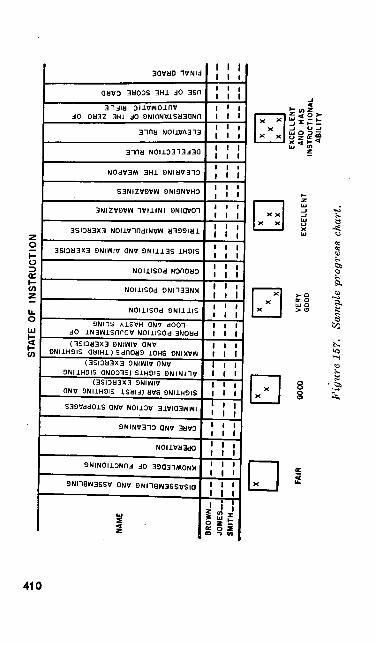
(Hfr
<es •
a •§
o3-
IH X
1
1
e_ 0Zm n
r i
BROWN. 1|n
DISASSEMBLING AND ASSEMBLING
KNOWLEDGE OF FUNCTIONING
OPERATION
CARE AND CLEANING
IMMEDIATE ACTION AND STOPPAGES
SIGHTING BAR (FIRST SIGHTING AND AIMING EXERCISE)
ALINING SIGHTS (SECOND SIGHTING AND AIMING EXERCISE)
MAKING SHOT GROUPS (THIRD SIGHTING AND AIMING EXERCISE)
PRONE POSITION ADJUSTMENT OF LOOP AND HASTY SLING
SITTING POSITION
KNEELING POSITION
CROUCH POSITION
SIGHT SETTING AND AIMING EXERCISE
TRIGGER MANIPULATION EXERCISE
LOADING INITIAL MAGAZINE
CHANGING MAGAZINES
CLEARING THE WEAPON
DEFELECTION RULE
ELEVATION RULE
UNDERSTANDING OF THE ZERO OF AUTOMATIC RIFLE
USE OF THE SCORE CARD
FINAL GRADE
graphs. The use of a 1000-inch range for prepara tory marksmanship training is satisfactory; how ever, it involves the use of a training area that may be required for a firing exercise.
208. PREPARATORY MARKSMANSHIP FIELD (TEMPORARY)
a. General. The parallel-line type and modi fied circular type preparatory fields are tempo rary installations. Therefore, when they are not in use for marksmanship training, the areas may be used for other purposes.
b. Organization of the Parallel-Line Type Preparatory Marksmanship Field. The class is organized in two parallel lines facing away from each other. The preparatory field is organized as shown in figure 158. Observe the following guides in organizing the training area:
(1) The aiming stakes are used during position exercises.
(2) The 1000-inch U.S. rifle caliber .30 Ml targets are used during trigger manipulation and automatic fire exer cises.
c. Organization of Circular Type Preparatory Marksmanship Field. The preparatory field is organized as shown in figure 159. Observe the following guides in organizing the training area:
(1) A bleacher for the class is placed on the rim of the circle as shown in figure 159. All periods of conference and
947041°—51—27411
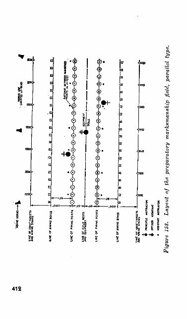
to
UN
C O
P AI
MIN
G BO
XES
UN
C O
F AI
MIN
G BO
XES
LIN
E O
r tO
OO
* TA
RG
ETS
- —
——
——
(V
AH
O A
WIN
G
STA
KES
|j
f
•
PRIN
CIP
LE
INST
RU
CTO
R
$
OFF
ICER
A
SSIS
TAN
T
• A
SSIS
TAN
T IN
STR
UC
TOR
Fig
ure
158.
La
yout
of
the
prep
arat
ory
mar
ksm
ansh
ip f
ield
, pa
ralle
l ty
pe.
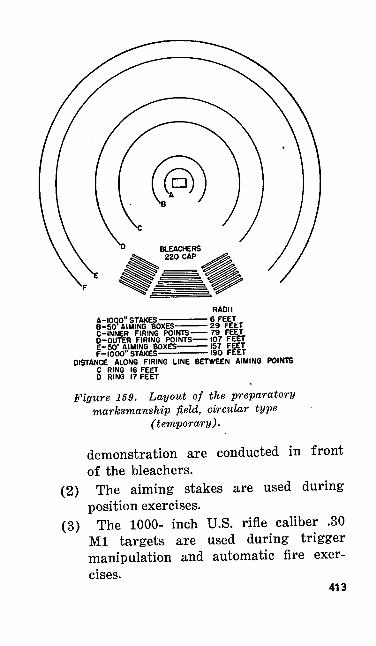
RADIIA-KJOO" STAKES ————— 6 FEET B-5CV AIMING BOXES————29 FEET C-INNER FIRING POINTS—— 79 FEET 0-OUTER FIRING POINTS—107 FEET E-50'AIMING BOXES———157 FEET F-1000' STAKES——————I9O FEET
DISTANCE ALONG FIRING LINE BETWEEN AIMING POINTS C RING 16 FEET D RING 17 FEET
Figure 159. Layout of the preparatorymarksmanship field, circular type
(temporary).
demonstration are conducted in front of the bleachers.
(2) The aiming stakes are used during position exercises.
(3) The 1000- inch U.S. rifle caliber .30 Ml targets are used during trigger manipulation and automatic fire exer cises.
413
(4) The public address system, if available, is located around the control stand so that announcements can be heard by everyone on the field.
209. PREPARATORY MARKSMANSHIP FIELD, (PERMANENT)
a. General. The preparatory marksmanship instruction circle is a permanent installation; therefore, this training area cannot be used for other instruction.
b. Organization of the Circular Type Prepar atory Marksmanship Field. The preparatory marksmanship instruction circle may consist of either four concentric circles (for two companies) or two concentric circles (for one company). The two-company installation (four concentric circles) is organized as shown in figure 160. Observe the following guides in organizing the preparatory marksmanship instruction circle for two companies.
(1) The field is centered around a demon stration platform which is fronted by bleachers for seating the class. A slid ing target frame, similar to the type used on the known-distance range, may be constructed on the rear of the demon stration platform for use as a training aid. Other training aids may be placed on the demonstration platform as re quired for each step of the instruction.
(2) The inner and outer circles consist of manually operated disappearing targets
414
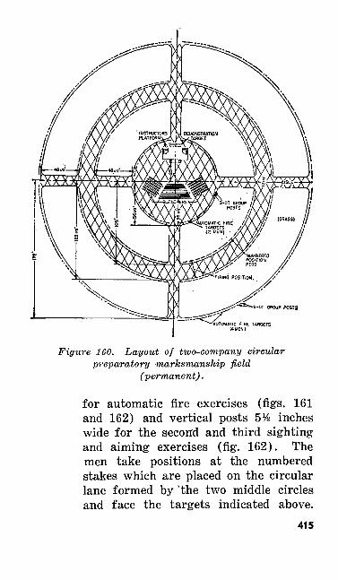
•SHUT GBOUP POSTS
Figure 160. Layout of two-company circularpreparatory marksmanship field
(permanent).
for automatic fire exercises (figs. 161 and 162) and vertical posts 5Ys inches wide for the second and third sighting and aiming exercises (fig. 162). The men take positions at the numbered stakes which are placed on the circular lane formed by 'the two middle circles and face the targets indicated above.
415
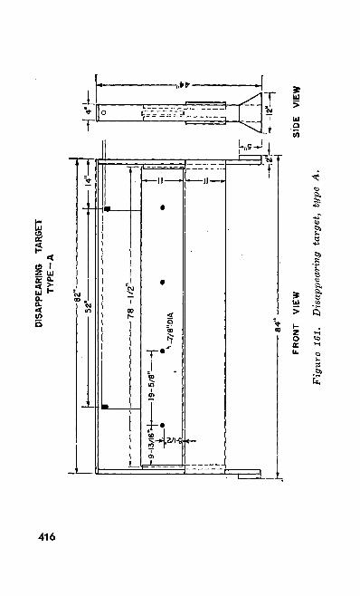
DISA
PPEA
RING
TA
RGET
T
YP
E-A
I -9-
13/1
6"-)
——
—1
i ±
SiH
—i i --
——
——
——
— • —
——
——
——
— 8
2" —
——
——
——
——
——
——
1 ——
——
——
——
——
——
——
——
——
——
——
——
——
——
——
—
——
——
——
——
——
——
— 7
8 -I
/a" —
——
——
——
——
——
-19-5
/8" —
——
| V_7/
8"D
IA
FR
ON
T
VIE
W
• ——
U
1
:(' — •
s j 1 jj
" :
— w
-
-isi
o
4" o i i i i i i ! i i
i i i — i
-12"
-
E \
" ^ E ^
\\
'1EW
Fig
ure
161.
D
isap
pear
ing
targ
et,
type
A.
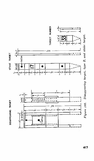
DISA
PPEA
RING
TA
RGET
STAK
E TA
RGET
- ——
13 !
4;
I 1 I -
~ i i LJ
h^
1 »
1 1 1 1 L7 i i i i i 1 ~ i i L.
--
"5 J •-, - \ ._i - \ u
3 D !j> T
hH o hi!
in
in
,iii Ul.
I I
I I
1 1
1 1
1 1
J
L
1 __
JL T T1 1 ir. o L
_L to -h "m 4-
V In CJ i "m -j- t
L
•5-1
/2^
*1 17 • • »
/ \ / \;
_ y
-7/8
"DIA
L
-r u it
\ J-.
1 TA
RG
ET
NUM
BER
M'H
41
-
1ft
—
tW u
1 \
/ I
_ j __ v
_ _U
Fig
ure
162.
D
isap
pear
ing
targ
et,
type
B,
and
stak
e ta
rget
.
If the installation is designed for one company, the men take positions on either circle facing the targets on the other circle.
(3) Lanes or aisles are provided so that the assistant instructors may move freely in supervising the work and so that the men may move from the bleach ers to their numbered positions on the circles.
(4) Several automatic fire targets can be operated simultaneously by connecting them with a draw rope.
(5) See figures 161 and 162 for necessary information concerning the dimensions of the disappearing targets, types A andB.
(6) The public address system, if available, is located around the control and demon stration stand so that announcements can be heard by everyone on the field.
210. SIGHTING AND AIMING EXERCISESa. General. During sighting and aiming-
exercises, the soldier learns how to ob tain the correct sight picture to hit the target in the center of the bull's eye.
6. Procedure.(1) Using the sight picture model or a
blackboard, explain and demonstrate the meaning and importance of the terms correct sight alinement and correct sight
418
picture. Emphasize that sight aline ment is more important than sight picture.
(2) Explain and demonstrate the three sighting and aiming exercises.
(3) Discuss incorrect sight alinement, in correct sight picture, and their effect on shot groups. To emphasize the effect of an error in sight alinement and sight picture, use a blackboard and chalk to illustrate the type of shot groups which result from different errors (fig. 125).
(4) Explain and emphasize the importance and demonstrate the correct method of blackening the sights.
(5) Explain the organization of the class for the coach-and-pupil method of in struction, showing how each member of the four man instructional group is kept busy. During practical work, one member of each group works with the M15 sighting device practicing setting up the correct sight alinement and the correct sight picture. The windage and elevation information on the back portion of the M15 sighting device cannot be used as it .pertains only to the Ml rifle.
(6) During practical work on the second and third sighting and aiming exercises, the members of the instructional group rotate until all men have made a satis factory shot group.
419
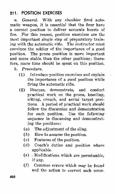
211. POSITION EXERCISESa. General. With any shoulder fired auto
matic weapon, it is essential that the firer have a correct position to deliver accurate bursts of fire. For this reason, position exercises are the most important single step of preparatory train ing with the automatic rifle. The instructor must convince the soldier of the importance of a good position. The prone position is more important and more stable than the other positions; there fore, more time should be spent on this position.
b. Procedure.(1) Introduce position exercises and explain
the importance of a good position while firing the automatic rifle.
(2) Discuss, demonstrate, and conduct practical work on the prone, kneeling, sitting, crouch, and aerial target posi tions. A period of practical work should follow the discussion and demonstration for each position. Use the following sequence in discussing and demonstrat ing the positions:
(a) The adjustment of the sling.( b ) How to assume the position.(c) Features of the position.(d) Coach's duties and position where
applicable.(e) - Modifications which are permissable,
if any. (/) Common errors which may be found
and the action to correct each error.420
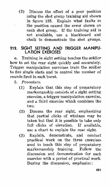
(3) Discuss the effect of a poor position using the shot group training aid shown in figure 125. Explain what faults in the position caused the error shown on each shot group. If the training aid is not available, use a blackboard and chalk to demonstrate the shot groups.
212. SIGHT SETTING AND TRIGGER MANIPU LATION EXERCISES
a. Training in sight setting teaches the soldier how to set the rear sight quickly and accurately. Trigger manipulation exercises train the soldier to fire single shots and to control the number of rounds fired in each burst.
b. Procedure.(1) Explain that this step of preparatory
marksmanship consists of a sight setting exercise, a trigger manipulation exercise, and a third exercise which combines the two.
(2) Discuss the rear sight, emphasizing that partial clicks of windage may be taken but that it is possible to take only full clicks of elevation. If available, use a chart to explain the rear sight.
(3) Explain, demonstrate, and conduct practical work on the three exercises used to teach this step of preparatory marksmanship training. Follow the discussion and demonstration for each exercise with a period of practical work. During the discussion, emphasize:
421
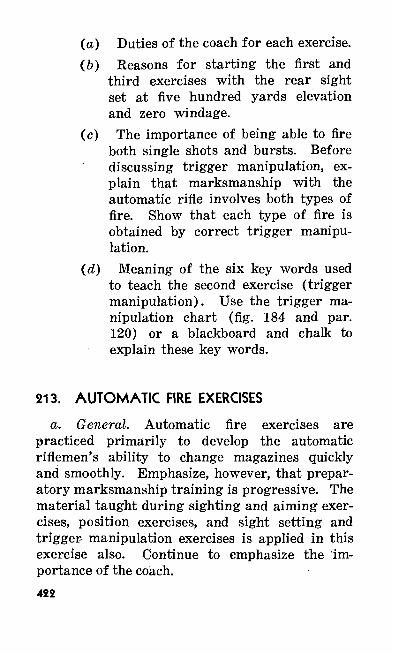
(a) Duties of the coach for each exercise.(6) Reasons for starting the first and
third exercises with the rear sight set at five hundred yards elevation and zero windage.
(c) The importance of being able to fire both single shots and bursts. Before discussing trigger manipulation, ex plain that marksmanship with the automatic rifle involves both types of fire. Show that each type of fire is obtained by correct trigger manipu lation.
(d) Meaning of the six key words used to teach the second exercise (trigger manipulation). Use the trigger ma nipulation chart (fig. 184 and par. 120) or a blackboard and chalk to explain these key words.
213. AUTOMATIC FIRE EXERCISES
a. General. Automatic fire exercises are practiced primarily to develop the automatic riflemen's ability to change magazines quickly and smoothly. Emphasize, however, that prepar atory marksmanship training is progressive. The material taught during sighting and aiming exer cises, position exercises, and sight setting and trigger- manipulation exercises is applied in this exercise also. Continue to emphasize the Im portance of the coach.422
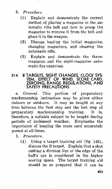
6. Procedure.(1) Explain and demonstrate the correct
method of placing a magazine in the au tomatic rifle belt and how to grasp the magazine to remove it from the belt and place it in the weapon.
(2) Discuss loading the initial magazine, changing magazines, and clearing the automatic rifle.
(3) Explain and demonstrate the three- magazine and the eight-magazine auto matic fire exercises.
214. B TARGETS, SIGHT CHANGES, CLOCK SYS TEM, EFFECT OF WIND, SCORE CARD, ZEROING, RANGE REGULATIONS, AND SAFETY PRECAUTIONS
a. General. This portion of preparatory marksmanship instruction may be given either indoors or outdoors. It may be taught at any time between the first step and the last step of preparatory marksmanship training. It is, therefore, a suitable subject to be taught during periods of inclement weather. Emphasize the importance of keeping the score card accurately posted at all times.
b. Procedure.(1) Using a target training aid (fig. 146),
discuss the B target. Explain that a shot cutting a division line or the edge of the bull's eye is considered in the higher scoring space. The target training aid should be so prepared that it can be
423
propped up during the discussion of this step. Either a chart or the B target may be used. In either case, have the dimensions indicated on the training aid.(2) Using a chart on sight changes or a blackboard, explain the elevation and deflection rules. Require the class to work several practical problems involv ing the use of these rules. Allow the class a few minutes to solve the prob lems; call on different soldiers for their answer; then write the problems on the blackboard, and solve them for the class.(3) Explain the method for determining the velocity of the wind through the use of the range flag or a few blades of grass. Using a blackboard, prepare problems by drawing several pictures of the range flag flying at various angles from the flag staff. Allow the class time to work each problem and then call on various soldiers for their answers. Solve the problems on the blackboard.(4) Using the chart on sight changes or a blackboard, explain the wind rule. Give several problems involving the use of the wind rule and require each member of the class to solve each problem. Call on individual soldiers for their solutions. Solve the problems on the blackboard.(5) Using a clock system chart (fig. 147), or a blackboard, explain and illustrate the use of the clock system to indicate
424
the direction and effect of the wind. Explain why winds from six and twelve o'clock have no appreciable effect on the path of the bullet, yet winds from other hours do have an effect depending on the strength of the wind and the direction from which it blows.
(6) Using a chart of the enlarged score card (fig. 151), or a blackboard, and the B target, explain and illustrate the cor rect procedure to be followed in making entries on the score card. Tell the class you will simulate.firing shots to zero the automatic rifle and will indicate where they hit by placing spotters in the target. Have each soldier solve several score card problems. Solve each problem, using the score card chart. The stated velocity and direction of the wind should be different for each problem. Include in this discussion how to obtain the cor rect zero of the automatic rifle from the score card.
(7) Discuss range procedures and safety precautions.
215. EXAMINATION BEFORE RANGE FIRINGa. General. The examination may be a writ
ten one, a practical work examination conducted by the county fair method, or a combination of the two. The combination type examination is the most desirable. The purpose of the examina tion is to determine whether each soldier is pre-
425
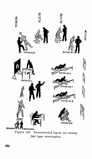
STATION NO. 9 •- ||
STUDENTS VI /I INSTRUCTORSFigure 163. Recommended layout for county
fair type examination.
426
pared to advance to the range firing phase of marksmanship training. For this reason, sched ule the examination far enough in advance of range firing to allow time for additional instruc-- tion when necessary. If the progress charts are properly maintained, they will indicate to you in advance of the examination which soldiers need additional instruction.
b. Procedure for Conducting a Combined Written and Practical Work Examination.
(1) Lay out the examination area as illus trated in figure 163.
(2) Assign a qualified noncommissioned officer to each station to examine the class.
(3) Rotate the class through each station, maintaining a record on each soldier.
(4) Establish an area where the written portion of the examination may be conducted.
(5) Conduct a critique during which time the examination questions and any other ones that may arise are answered.
216. RANGE ORIENTATIONa. The equipment required for the orientation
before range firing is listed in paragraph 185.b. Range firing is not only a continuation of
preparatory marksmanship training but it also serves as a practical test of what soldier has learned during the preceding periods of instruc tion. Before allowing any firing, conduct a period
947041°—51—28427
of range orientation and discuss the following subjects:
(1) The need for continuously applying what was learned in preparatory marks manship training.
(2) The importance of coaching and the duties of the coach.
(3) The use of spotters and disks.(4) The use of dummy cartridges.(5) The use of telephone (appropriate
telephone expressions).(6) The importance of keeping the score
card accurately posted.(7) Zeroing.(8) Striving for accuracy before speed.(9) The course to be fired.(10) Range regulations and safety pre
cautions.
217. TRANSITION FIRINGa. Transition firing is designed to bridge the
gap between known distance firing and field target firing. Individual combat marksmanship is de veloped by requiring the firer to search for an in distinct target, estimate the range to it, and place accurate fire on it within a limited time. The initial step in transition firing is instruction in the theory and use of the battle sight. It includes the use of the aiming point on targets within 400 yards and the application of leads to moving personnel (par. 169). Three phases of428
transition firing (tables VI, VII, and VIII) are prescribed for the automatic riflemen in the standard qualification course.
b. The chief instructor is responsible for:(1) Securing, training, and rehearsing,
commissioned and noncommissioned as sistants and demonstrators before in struction begins.
(2) Arranging for equipment, ranges, pj,t details, and communication facilities, to have them available for rehearsals and instruction.
c. The troops being trained in transition firing and in the technique of engaging moving targets must have completed known distance firing with the automatic rifle and the training in range estimation (FM23-5).
218. TABLE VI, PRELIMINARY INSTRUCTION FOR TRANSITION FIRING
a. Instruction firing in the method of engaging a silhouette target and in the use of the aiming point is conducted on the known distance range in much the same manner as known distance firing. The target is made up locally by pasting two paper kneeling silhouette (E) targets (ORD Stock No. L001-60-06874) 18 inches apart and equal distance from the center of the target panel on-a-biank target frame (fig. 164). In about the center of the body of the left silhouette, paste or stencil an aiming point at least 8 inches square. A sheet of white letter size paper (8" x lO 1/^"),
429

io 1/2"
291/2"
51/2" 51/2'
SILHOUETTE
tr-NO.i NO.2-1
71/2" -191/2- -191/2"--72"-
Figure 164. Target wsed for instruction in the vse of the aiming point (table VI).
with the lower 12 inches above the bottom of the silhouette may be used.
b. Starting on the 300 yard firing line, shot groups are fired on the No. 1 silhouette using the aiming point to confirm the battle sight and to acquaint the firer with the part of the target that he is to shoot for. Targets are pulled and the shot groups spotted after each burst. The No. 2 unmarked silhouette target is then fired on with430
the firer trying for hits on the same part of the target. In a like manner, firing is conducted at 200 yards and 400 yards to provide instruction in the use of the aiming point.
(1) During the firing of table VI, give con current rear area instruction to small groups in anticipation of firing tables VII and VIII. For example, have the groups practice assuming the combat firing positions, using the position mock- ups to be used on table VII, and have them practice the crouch position and alertness while advancing.
(2) There is no prescribed sequence for firing transition tables VII and VIII. Both phases of the standard qualification course may be conducted at the same time and groups alternated on the ranges.
c. Require each man to fire table VI at least once and demonstrate proficiency in the use of the battle sight and aiming point before allowing him to progress to table VII.
219. TABLE VII, TRANSITION FIRING
a. A field target range like the one shown in figure 165 is used for firing table VII. Ranges may vary slightly to fit local terrain conditions. Except for lane 6, no range will be over 400 yards. This layout is superimposed on the first six lanes of the rifle transition range (FM 23-5).
431
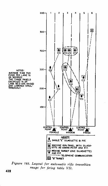
600-
500-
NOTES:AVERAGE TIME PER FIRER PER LANE IS 55 SECONDS. THE THREE PANELS ENCIRCLED IN AR LANE NO. 2 ARE RAISED AND LOWERED SIMUL TANEOUSLY.
CONTROL POINT
CONTROL . __ POINT £f
FOXHOLE WINDOW
_POINT A3
PRONE
LEGEND , SINGLE '£' SILHOUEKE a PIT.
[i] MACHINE GUN PANEL, WITH SILHOU- Q ETTE AS AIMING POINT AND PIT.fri MOVING TARGET (ONE SILHOUETTE)• AND PIT.
——————— TELEPHONE COMMUNICATION M "8" TARGET
432
Figure 165. Layout for automatic rifle transition range for firing table VII.
b. The firing line is controlled by an officer who is assisted by a noncommissioned officer at each firing point. Each lane has a control point (telephone) operator who controls the raising or lowering of the targets by verbal messages to the pit operators.
c. The noncommissioned officers at each firing point—
(1) Receive and record individual scores when obtained by the control point operator.
(2) Are constantly on the alert to see that safety precautions are observed and, on orders of the officer in charge, check weapons for clearance. -
d. Firing is controlled as follows:(1) On command of the officer in charge,
each firer examines his automatic rifle in preparation for firing and assumes the position required for the lane he is using.
(2) A firer is assigned to each lane before the exercise begins. After completing a lane, the firers on lanes 1 and 2 dis place to the right to successive positions. The man on lane 3 moves left to lane 1. Movement is made only on command of the officer in charge after all weapons have been cleared.
(3) When the firers have signaled "ready" the officer in charge commands: ONE MAGAZINE OF 20 ROUNDS, LOAD. READY ON THE RIGHT? READY
433
ON THE LEFT? READY ON THE FIRING LINE. COMMENCE FIRING. At the command to commence firing, the control point operators assume control of target operations. The three lanes are operated together.
(4) The control point operator for lane 1 directs that one of the four silhouettes be raised. After 7 seconds, the target is lowered and the operator orders that another target be raised. This procedure is repeated until all four targets have been exposed. The order in which the silhouettes appear is varied.
(5) The control point operator for lane 2 directs that either the diagonal target group or the lateral target group be exposed. After expending one magazine of 20 rounds, or when the target disap pears, the automatic rifleman reloads immediately in anticipation of the second target. Each target is exposed for 20 seconds or until one magazine is ex pended, whichever happens first. The lapse between the disappearance of one target and the appearance of the other is kept to the minimum required for the automatic rifleman to reload.
(6) The control point operator for lane 3 calls for the appearance of one of the moving targets. After it has been ex posed for 8 seconds, the second moving target is caused to appear. Targets
434
should be so controlled that they traverse in opposite directions. After the second moving target disappears, the B target is ordered raised and is left exposed for 10 seconds. The firer estimates the range, sets his sights, and fires his re maining ammunition at this target.
(7) After the last target has disappeared, the officer in charge gives the command CEASE FIRING, CLEAR ' RIFLES. When the line has been cleared, control point operators on signal from the officer in charge order the pit detail to mark targets.
(8) It is desirable that the pits and targets be so constructed that the men need not leave the pits to score the targets. If this is not possible, the men in the pits display a red flag over their pits after clearance from the firing line and move quickly to the targets, note the number of hits, and mark or paste the bullet holes. After marking the targets, the men return to their pits, lower the red flag, and report the number of hits to the control point operator. This infor mation is given to the noncommissioned officer in charge of the firing point who enters the score on the firer's score card.
435
220. TABLE VIII, TRANSITION (QUICK) FIRINGA field target range of the type shown in figure
166 is used for firing table VIII. This range may be superimposed on the rifle quick fire transition range (FM 23-5). The number of lanes is deter mined by local terrain and safety conditions.
a. Target Operation.(1) Targets between phase lines are ex
posed in sequence on signal of the control officer. Signals should not be visible or audible to the firer.
(2) Phase lines are placed after targets 4 and 7 to permit the firer to reload and to assist in the enforcement of safety precautions.
b. The Crouch Position. This position is used during the automatic rifleman's advance to place quick fire on the surprise targets.
c. Firing Procedure. The automatic rifleman starts from the prone position with 3 magazines of 20 rounds each in his belt and none in his auto matic rifle.
(1) On order of the lane control officer or noncommissioned officer, the automatic rifleman rises, adjusts the sling for the crouch position, loads one magazine into his automatic rifle, and moves down the lane on the alert. If parallel lanes are being used, the lane control officer must keep the automatic riflemen abreast as they move forward. As the targets are
436
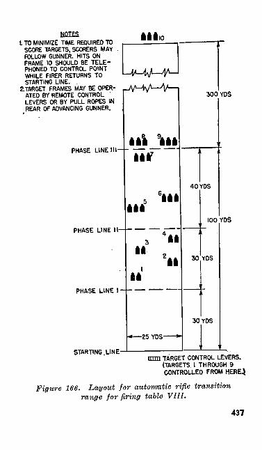
t TO MINIMIZE TIME REQUIRED TO SCORE TARGETS, SCORERS MAY - FOLLOW GUNNER. HITS ON FRAME 10 SHOULD BE TELE PHONED TO CONTROL POINT WHILE FIRER RETURNS TO STARTING LINE.
2.TARGET FRAMES MAY BE OPER ATED BY REMOTE CONTROL ' LEVERS OR BY PULL ROPES IN REAR OF ADVANCING GUNNER.
AAAio
PHASE LINE III-- —— ————•
PHASE LINE II-
PHASE LINE 1 •
STARTING .LINE-
All 9AAA All7
II
AA
III
II
II
-25 YDS-
300 YDS
40 YDS
100
30
YDS
YDS
30 YDS
mm TARGET CONTROL LEVERS. (TARGETS 1 THROUGH 9 CONTROLLED FROM. HERE)
Figure 166. Layout for automatic rifle transition range for firing table VIII.
437
exposed, 5 rounds are fired at the double silhouettes and 6 rounds at the triple silhouettes in short, two- or three- round, bursts.
(2) The double silhouette targets are ex posed for 3 seconds. The triple silhouet tes are exposed for 4 seconds. Targets 8 and 9 are exposed simultaneously, and remain up for 6 seconds. Target 10, the distant target, is exposed for 20 seconds.
(3) In firing at the distant target, the auto matic rifleman, having advanced beyond targets 8 and 9, assumes the prone posi tion, adjusts the sights, and fires the remaining ammunition from the third and last magazine. This target is used to impress the automatic rifleman with the importance of taking a position to cover the reorganization of his squad after capturing an objective.
221. ALTERNATE TRANSITION RANGE FIRINGIf local facilities are not adequate for transition
firing as prescribed in the standard qualification course (tables VII and VIII) described above, tables IX and X may be fired as alternates. This course for the automatic rifleman corresponds, in range requirements, time, and procedure, with the alternate course for the U.S. rifle caliber .30, Ml.
438
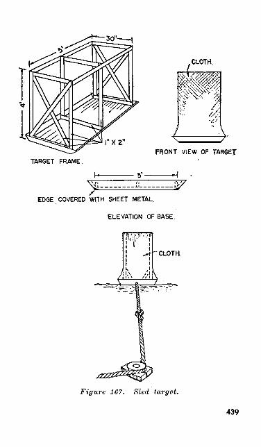
X2"
FRONT VIEW OF TARGETTARGET FRAME.
5'-
EDGE COVERED WITH SHEET METAL.
ELEVATION OF BASE.
CLOTH
Figure 167. Sled target.
439
222. MOVING VEHICLE MARKSMANSHIPa. While there is no prescribed course for
training in firing on moving vehicles, with inge nuity and imagination an instructor can devise instructive exercises. The subject lends itself to rear area concurrent training. Examples of this type of training are practiced in—
(1) Speed estimation, using a vehicle mov ing at predetermined speeds.
(2) Tracking, having men track along a fence line to maintain a uniform swing.
6. Moving target range firing is valuable train ing if time and facilities permit.
(1) A sled target, with a low center of gravity, of the type shown in figure 167 can be constructed of scrap material and can be readily towed over rough ground.
(2) For towing with a vehicle, use 500 yards of % incn rope. The pulley seen in figure 167 is a channel wheel bolted to a wooden or metal base which is firmly staked down. When a knot tied in the tow rope 10 to 12 feet ahead of the target hits the wheel, the rope is thrown off the pulley and causes the target to change direction. A schematic layout for a moving target range is shown in figure 168.
440
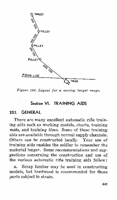
i TARGET
TRUCK
Figure 168. Layout for a moving target range.
Section VI. TRAINING AIDS
223. GENERAL
There are many excellent automatic rifle train ing aids such as working models, charts, training mats, and training films. Some of these training aids are available through normal supply channels. Others can be constructed locally. Your use of training aids enables the soldier to remember the material longer. Some recommendations and sug gestions concerning the construction and use of the various automatic rifle training aids follow;
a. Scrap lumber may be used in constructing models, but hardwood is recommended for those parts subject to strain.
441
b. All charts and models should be painted with highly contrasting colors. These colors help to identify the various parts shown on the chart or model.
c. Mount wooden working models on stands that are all of the same height. In some cases, two models can be made to work together as they actually function in the automatic rifle.
d. The working models are merely designed to show the functioning of the parts, therefore the models lack some of the refinements of the weapon. Some of the parts on the model- are cut away to show other parts located in the rear which play an important role in the functioning.
e. Generally, a scale of ten to one will enlarge drawings or models to a size sufficient to be seen clearly at a distance of 75 feet.
/. All lettering on charts, models, and other training aids must be large enough to read easily. Lettering 2^ inches high can be seen at a distance of 75 feet.
g. Charts painted or drawn on paper are just as satisfactory as those painted on wood. How ever, they are not as durable.
h. Before using a chart to illustrate portions of your instruction, explain how certain parts are identified by colors; for example: "This part painted blue is the bolt lock."
i. Some charts may be used as effective sub stitutes for large wooden working models.
3. A useful chart may be made to illustrate any portion of the field manual.442
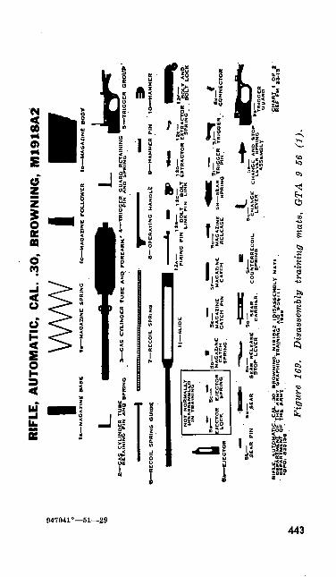
RIF
LE,
AU
TOM
ATI
C,
CA
L. .
30,
BR
OW
NIN
G,
M19
18A
2
VWW
I
MA
GA
ZIN
E
BA
SE
«-*
E-?
»S
.Y.!i
G' IK
R y
1_C
YL
IND
ER
T
UB
E
AN
D
FO
RE
AR
M'
"F-T
R.O
OE
R
CR
OU
> '
F""
N° "
*u
S?
-fl*
\?M
EX
'TR
AC
TO*
E¥T
R. <
5l°
". J
S.V
l55
!?K
..
1
sifSppL
EE»viE
." cfis
rER.
""SirN
^0"-
5\HEAvNe
GRe cHu
4>«5, As
N,DR,gi0
1- «T-
^OOER
AS
SE
MB
LY
G
UA
RD
DE
PA
•C
PO
:
CH
AR
T
f O
F_
R
EF
F
M
23-1
Fig
ure
169.
D
isas
sem
bly
trai
ning
mat
s,
GTA
9
56
(1).
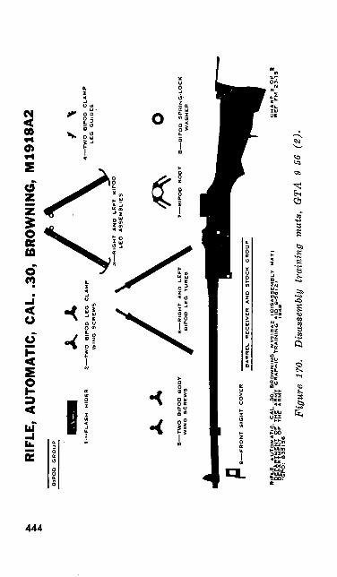
RIF
LE,
AU
TOM
ATI
C,
CA
L. .
30,
BR
OW
NIN
G,
M19
18A
2B
IPO
D
GR
OU
P 1—
FL
AS
H
HID
ER
2—
—
** /\ "
TW
O
BIP
OD
L
EO
C
L«
MP
*
^
4——
TW
O
BIP
OD
C
UA
MP
WIN
G
SC
RE
WS
*
%
LC
G
="'°
ES
^
V3—
—R
IGH
T
AN
D
LE
FT
B
IPO
D
LE
G
AS
SE
MB
LIE
S
X
AB
IPO
D
SP
RIN
G-L
OC
K
WA
SH
ER
Fig
ure
170.
D
isas
sem
bly
trai
ning
mat
s,
GTA
9-
56 (
2).
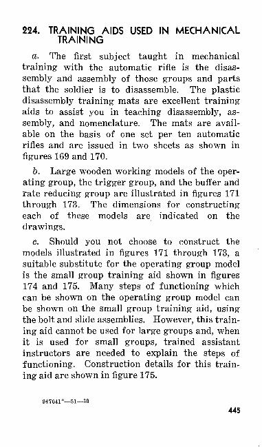
224. TRAINING AIDS USED IN MECHANICAL TRAINING
a. The first subject taught in mechanical training with the automatic rifle is the disas sembly and assembly of those groups and parts that the soldier is to disassemble. The plastic disassembly training mats are excellent training aids to assist you in teaching disassembly, as sembly, and nomenclature. The mats are avail able on the basis of one set per ten automatic rifles and are issued in two sheets as shown in figures 169 and 170.
b. Large wooden working models of the oper ating group, the trigger group, and the buffer and rate reducing group are illustrated in figures 171 through 173. The dimensions for constructing each of these models are indicated on the drawings.
c. Should you not choose to construct the models illustrated in figures 171 through 173, a suitable substitute for the operating group model is the small group training aid shown in figures 174 and 175. Many steps of functioning which can be shown on the operating group model can be shown on the small group training aid, using the bolt and slide assemblies. However, this train ing aid cannot be used for large groups and, when it is used for small groups, trained assistant instructors are needed to explain the steps of functioning. Construction details for this train ing aid are shown in figure 175.
947041°—51—30
445
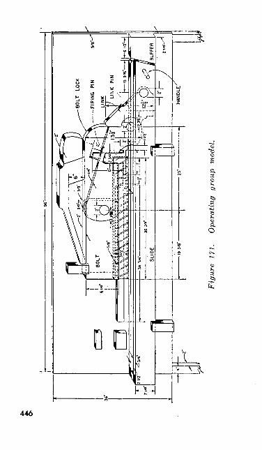
Fig
ure
171.
O
pera
ting
grou
p m
odel
.
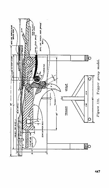
Fig
ure
172.
Tr
igge
r gr
oup
-mod
el.
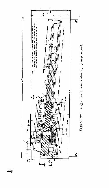
4t
CO
NOTE
: US
E SC
REEN
DO
OR
SPRI
NGS
FOR
MOVI
NG
PART
S.MO
VING
PAR
TS M
ADE
FROM
V
*" T
HICK
NESS
PLT
WOO
D. :
AC
TUAT
OR
a BU
FFER
SPR
INQS
ARE
PAI
NTED
ON.
.
Fig
ure
173.
B
uffe
r an
d ra
te r
educ
ing
grou
p m
odel
.
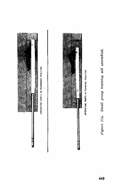
OP
ER
ATI
NG
PA
RTS
IN
REA
RW
ARD
P
OS
ITIO
N
OPE
RAT
ING
PA
RTS
IN
FO
RWAR
D P
OS
ITIO
N
figu
re 1
74.
Smal
l gr
oup
trai
ning
ai
d as
sem
bled
.
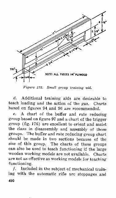
NOTE: ALL PIECES 1/4" PLYWOOD
Figure 175. Small group training aid.
d. Additional training aids are desirable to teach loading and the action of the gas. Charts based on figures 94 and 96 are recommended.
e. A chart of the buffer and rate reducing group based on figure 97 and a chart of the trigger group (fig. 176) are excellent to orient and assist the class in disassembly and assembly of those groups. The buffer and rate reducing group chart should be made in two sections because of the size of this group. The charts of these groups can also be used to teach functioning if the large wooden working models are not available. Charts are not as effective as working models for teaching functioning.
/. Included in the subject of mechanical train ing with the automatic rifle are stoppages and450
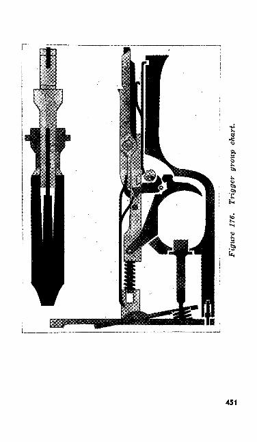
Figu
re 1
76.
Trig
ger
grou
p ch
art.
immediate action. Certain stoppages are more common than others. To show five of the more common stoppages, charts based on figures 112 through 116 may be used.
g. Other training aids that can be used to assist in presenting mechanical training with the automatic rifle are—
(1) Training films and film strips.(2) Graphic Training Aid 9-6.(3) Cut-away model of the automatic rifle.
225. TRAINING AIDS USED IN PREPARATORY MARKSMANSHIP TRAINING
The training aids used to assist in teaching preparatory marksmanship with the automatic rifle are explained in the order in which they are used.
226. SIGHTING AND AIMING EXERCISESa. A sight picture device similar to the one
shown in figure 177 can be used to show the correct sight alinement and the correct sight picture as well as the errors in sight alinement and sight picture.
b. During the first sighting and aiming exer cise, the sighting and aiming bar is used in teach ing as well as testing the pupil's ability to set up the correct sight alinement and correct sight picture. A detailed drawing of the sighting and aiming bar is given in figure 178.
c. The sighting disk used in the second and third sighting and aiming exercises is shown in452
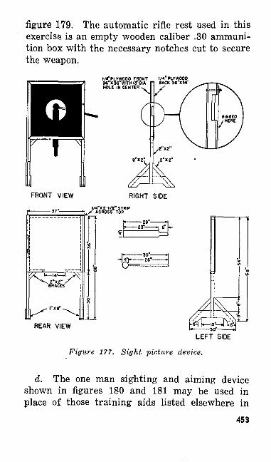
figure 179. The automatic rifle rest used in this exercise is an empty wooden caliber .30 ammuni tion box with the necessary notches cut to secure the weapon.
I/<PLYWOOD FRONT 56"X36 WITHI3 OIA HOLE IN CENTER «.
RIGHT SIDEl/4"X2-l/e" STRIP
ACROSS TOP
•£&
REAR VIEWLEFT SIDE
Figure 177. Sight picture device.
d. The one man sighting and aiming device shown in figures 180 and 181 may be used in place of those training aids listed elsewhere in
453
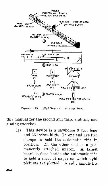
TARGET(PAINTED WHITE WITH
-BLACK BULLS-EYE)
FRONT SIGHT (PAINTED BLACK)
REAR SI6HT-PEEP OR OPEN (PAINTED BLACK)
© SIDE VIEW
H HTARGET '(A)
FRONTIGHTON DOTTED LINE
(F)
FOLDED L"SHAPE (0)
0 CONSTRUCTION
HOLE 1/2" FROM TOP CENTER (H)
Figure 178. Sighting and aiming bar.
this manual for the second and third sighting andaiming exercises.
(1) This device is a sawhorse 9 feet long and 36 inches high. On one end are two clamps to hold the automatic rifle in position. On the other end is a per manently attached mirror. A target board is fixed beside the automatic rifle to hold a sheet of paper on which sight pictures are plotted. A split handle fits
454
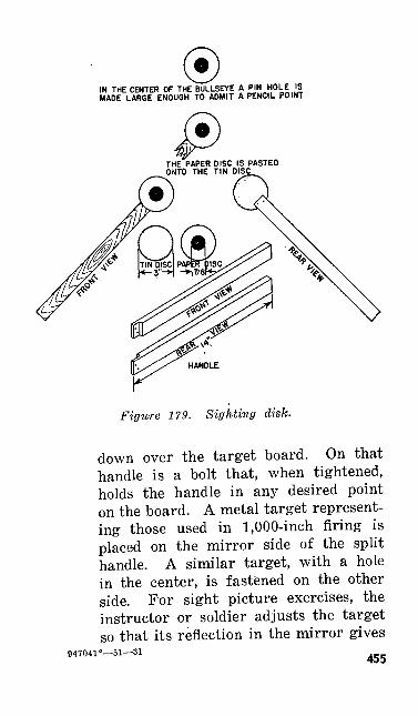
IN THE CENTER OF THE BULLSEYE A PIN HOLE IS MADE LARGE ENOUGH TO ADMIT A PENCIL POINT
THE PAPER DISC IS PASTED ONTO THE TIN DISC
Figure 179. Sighting disk.
down over the target board. On that handle is a bolt that, when tightened, holds the handle in any desired point on the board. A metal target represent ing those used in 1,000-inch firing is placed on the mirror side of the split handle. A similar target, with a hole in the center, is fastened on the other side. For sight picture exercises, the instructor or soldier adjusts the target so that its reflection in the mirror gives
947041°—51—31 455
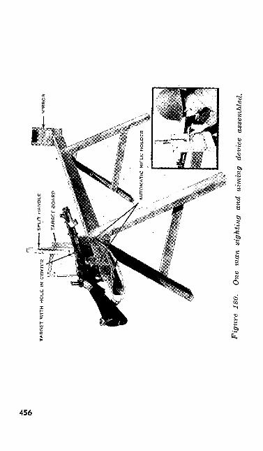
TAR
GET
WIT
H H
OL
E I
N C
EN
TE
R
Fig
ure
180.
O
ne m
an s
ight
ing
and
aim
ing
devi
ce
asse
mbl
ed.
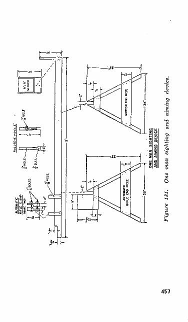
AUTO
MAT
IC
RIFL
E CL
AMP
(MAK
E Tw
o)
BULLSEYE HANDLE'
^ I
2J-L
itli.
/
AUTO
MAT
IC
/•
RIF
LE
END
PIE
-36
"-
ONE
MA
N
SIG
HTI
NG
A
ND
A
IMIN
G
DEV
ICE
Fig
ure
181.
O
ne m
an s
ight
ing
and
aim
ing
devi
ce.
the correct sight picture. For shot group exercises, the correct sight picture is made and then marked on the paper by inserting a pencil point through the hole in the target as shown in figure 180.
(2) Among the advantages of the one man device over the other training aids are the following: there is no requirement for markers, consequently the number of men required to conduct training is reduced; as no targets are used at 1,000 inches it is possible to conduct this train ing in a restricted area or indoors; be cause only one man is required to operate it, individual soldiers can use the device on their own time to practice sighting and aiming by plotting shot groups. The only disadvantages of the one man device result from its size and weight. When not in use it takes up considerable storage space and it is not easily moved from one training area to the other.
227. POSITIONS
A series of charts like those shown in figure 182 can be used to illustrate the effect of errors in the prone position.
458
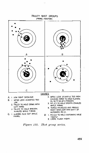
FAULTY SHOT GROUPS(PRONE POSITION)
A. I. LOW RIGHT SHOULDER
B, I BIPOD LEGS ADJUSTED TOO LOW
2. FAILED TO HOLD DOWN WITH LEFT HAND.
3. FAILED TO HOLD BREATH.INHALED WHILE FIRING.
& 1. ELBOWS SLID OUT WHILE FIRING.
2. BIPOD LEGS ADJUSTED TOO HIGH CAUSING FIRER TO HOLD ELBOWS IN, SETTING UP A TENSION.
3. FAILED TO HOLD' BREATH. EXHALED WHILE FIRING.
4. TENSED MUSCLES AND RAISED RIGHT SHOULDER INTO BUTT OF AUTOMATIC RIFLE.
I. FAILED TO HOLD AUTOMATIC RIFLETIGHTLY
2 LOOSE FLASH HIDER.
Figure 182. Shot group series.
459
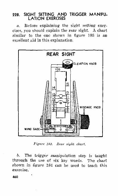
228. SIGHT SETTING AND TRIGGER MANIPU LATION EXERCISES
a. Before explaining the sight setting exer cises, you should explain the rear sight. A chart similar to the one shown in figure 183 is an excellent aid in this explanation.
REAR SIGHT
ELEVATION KNOB
WIND GAGE
WINDAGE KNOB
Figure 183. Rear sight chart.
b. The trigger manipulation step is taught through the use of six key words. The chart shown in figure 184 can be used to teach this exercise.460
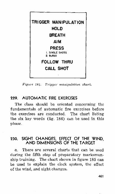
TRIGGER MANIPULATIONHOLD
BREATHAIM
PRESS1. SINGLE SHOTS2. BURST
FOLLOW THRU CALL SHOT
Figure 184. Trigger manipulation chart.
229. AUTOMATIC FIRE EXERCISESThe class should be oriented concerning the
fundamentals of automatic fire exercises before the exercises are conducted. The chart listing the six key words (fig. 184) can be used in this phase.
230. SIGHT CHANGES, EFFECT OF THE WIND, AND DIMENSIONS OF THE TARGET
a. There are several charts that can be used during the fifth step of preparatory marksman ship training. The chart shown in figure 185 can be used to explain the clock system, the effect of the wind, and sight changes.
461
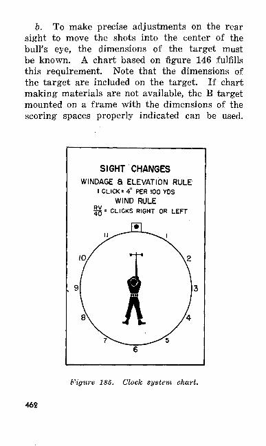
b. To make precise adjustments on the rear sight to move the shots into the center of the bull's eye, the dimensions of the target must be known. A chart based on figure 146 fulfills this requirement. Note that the dimensions of the target are included on the target. If chart making materials are not available, the B target mounted on a frame with the dimensions of the scoring spaces properly indicated can be used.
SIGHT CHANGESWINDAGE 8 ELEVATION RULE
I CLICK =4" PER 100 YDSWIND RULE
1^ = CLICKS RIGHT OR LEFT
Figure 185. Clock system chart.
462
c. The importance of the score card cannot be over-emphasized. A chart based on figure 151 or 152 is desirable during this instruction. The chart is placed on plywood, masonite, or some similar material. As blackboard paint is used for the background, this training aid may be used several times to explain and demonstrate typical score card problems. A chart can be prepared for both the slow fire and automatic fire portions of the scorecard.
463
CHAPTER 7
SAFETY PRECAUTIONS
231. GENERALSafety is the first concern of everyone during
any exercise in which weapons are used. The Army has prescribed certain safety precautions. When everyone follows these precautions care fully, accidents do not occur. Start observing safety precautions as soon as you receive your weapon. You are responsible for your own safety and for that of those aroung you. You are ex pected and required to assist in enforcing safety precautions at all times.
232. SAFETY PRECAUTIONS TO BE OBSERVED AT ALL TIMES
The more important safety precautions to be observed at all times are:
a. Never playfully or carelessly point any weapon at anyone or in any direction where people
• may be.b. Always assume that a weapon is loaded
until it has been thoroughly inspected and found to contain no live ammunition.
c. Never carry your automatic rifle with the operating parts to the rear. The only exception to this rule is when you are in combat and are in464
contact with the enemy or when you are engaged in certain training exercises and are specifically told to carry your automatic rifle with the operat ing parts to the rear.
d. Except when specifically instructed other wise (c above), always carry your automatic rifle with the muzzle pointing up.
e. Never place an obstruction of any kind in the bore or muzzle of your automatic rifle. Al ways examine the bore before starting to fire.
/. Except on a firing line where both live ammunition and dummy cartridges are used, always take particular care with dummy ammuni tion to make sure that no live cartridges are present.
gr. Never fire blank ammunition at anyone who is closer than 20 yards.
233. SAFETY PRECAUTIONS TO BE OBSERVED DURING MECHANICAL TRAINING
The more important safety precautions to be observed during mechanical training are:
a. Check the chamber and receiver to see that no live cartridges are in the automatic rifle.
b. Check all magazines, spare parts kits, and other containers for live ammunition.
c. Check each dummy cartridge carefully to make sure that it is not a live cartridge and check each empty cartridge case to make certain that it does not have a live primer.
465
234. SAFETY PRECAUTIONS TO BE OBSERVED DURING PREPARATORY MARKSMAN SHIP TRAINING
During preparatory marksmanship training, the primary safety precaution is to make certain that no live cartridges are present. The precau tions listed in paragraph 233 must be followed rigidly. Because preparatory marksmanship training prepares you to fire live ammunition on the range, you must learn to observe certain safety precautions during this period that will apply on the range. These safety precautions are enforced on the preparatory marksmanship field:
a. Keep the automatic rifle pointed in the air and toward the targets.
6. On the command CEASE FIRING, drop your hands from the weapon if you are in the prone position. In the other positions, take your finger off the trigger and out of the trigger guard.
c. Before leaving the preparatory marksman ship line, clear your automatic rifle; remove the magazine, cock the weapon, and then press the trigger.
d. Never pull back on the operating handle or insert a magazine in the automatic rifle away from the preparatory marksmanship line.
466
235. SAFETY PRECAUTIONS TO BE OBSERVED DURING RANGE FIRING
a. It is the responsibility of all officers conduct ing firing with the automatic rifle to know the pertinent safety rules in the following publi cations :
(1) SR 385-310-1.(2) TM 9-1990.(3) Local (installation or unit) safety
regulations.
b. It is also the officer's responsibility to familiarize you with such of the above regulations as you need to know before going on the range.
c. Besides the safety precautions described above that you will be given, observe these addi tional precautions while on the range:
(1) Do not draw or issue ammunition un til the officer in charge of firing directs you to do so.
(2) Do not load or commence firing until the command to do so has been given.
(3) Once you pick up your automatic rifle, keep it pointing in the air and down range.
(4) Load and unload your weapon only on the firing line.
(5) Do not remove your weapon from the firing line until it has been cleared and inspected and until you have been au thorized to remove it.
467
(6) Do not cock the weapon or insert a magazine while you are behind the firing line.
(7) While you may practice sight setting, trigger manipulation, and magazine changing on an extension of the firing line, never practice these techniques behind the firing line.
(8) Never step in front of the firing line for any reason unless the officer in charge of firing gives you permission.
(9) As soon as you have completed firing, or at the command CLEAR WEAPONS, clear your automatic rifle; remove the magazine, cock the weapon, and press the trigger to allow the operating parts to go forward.
(10) When you hear the command CEASE FIRING, drop both hands to the ground if you are in the prone position, and wait for further instructions. In the other positions, remove your finger from the trigger and out of the trigger guard. Anyone may give the command CEASE FIRING when it is necessary for safety.
(11) Take proper care of the ammunition. Keep it free from grease and do not allow it to remain in the direct rays of the sun for long periods of time. Inspect the ammunition carefully and turn in any defective cartridges includ ing misfires.
468
(12) Do not fire if a red flag is displayed above the pits.
(13) Do not fire unless a red streamer is displayed at a prominent point on the range. This streamer serves as a warn ing to everyone in the vicinity that firing is in progress.
(14) Before throwing away any ammuni tion cartons, make sure that they do not contain any cartridges.
(15) Before turning in your empty car tridge cases, inspect each one to make certain that it does not contain a live primer and that no live cartridges are present.
(16) Before you are permitted to leave the range, you will be inspected by the officer in charge of firing or his repre sentatives to make certain that you have no live cartridges on you or in your automatic rifle or magazines.
(17) Before firing on any moving target range, the right and left safety limits will be pointed out by the officer in charge of firing. Do not fire unless you clearly understand these safety limits. Do not fire outside of these limits.
469
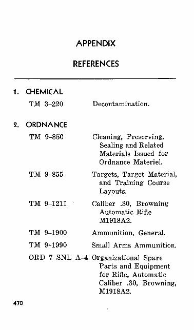
APPENDIX
REFERENCES
1. CHEMICALTM 3-220
2. ORDNANCETM 9-850
TM 9-855
TM 9-1211
TM 9-1900
TM 9^-1990
Decontamination.
Cleaning, Preserving, Sealing and Related Materials Issued for Ordnance Materiel.
Targets, Target Material, and Training Course Layouts.
Caliber .30, Browning Automatic Rifle M1918A2.
Ammunition, General.
Small Arms Ammunition.ORD 7-SNL A-4 Organizational Spare
Parts and Equipment for Rifle, Automatic Caliber .30, Browning, M1918A2.
470
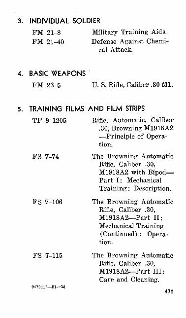
3. INDIVIDUAL SOLDIERFM 21-8 Military Training Aids. FM 21-40 Defense Against Chemi
cal Attack.
4. BASIC WEAPONSFM 23-5 U. S. Rifle, Caliber .30 Ml.
5. TRAINING FILMS AND FILM STRIPSTF 9-1205 Rifle, Automatic, Caliber
.30, Browning M1918A2 —Principle of Opera tion.
FS 7-74 The Browning Automatic Rifle, Caliber .30, M1918A2 with Bipod— Part I: Mechanical Training: Description.
FS 7-106 The Browning Automatic Rifle, Caliber .30, M1918A2—Part II: Mechanical Training (Continued) : Opera tion.
FS 7-115 The Browning Automatic Rifle, Caliber .30, M1918A2—Part III: Care and Cleaning.
947041°—51—32471
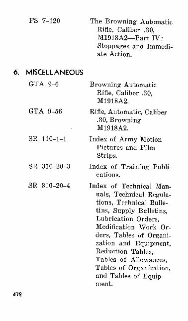
FS 7-120 The Browning Automatic Rifle, Caliber .30, M1918A2—Part IV: Stoppages and Immedi ate Action.
6. MISCELLANEOUSGTA 9-6 Browning Automatic
Rifle, Caliber .30, M1918A2.
GTA 9-56 Rifle, Automatic, Caliber .30, Browning M1918A2.
SR 110-1-1 Index of Army Motion Pictures and Film Strips.
SR 310-20-3 Index of Training Publi cations.
SR 310-20-4 Index of Technical Man uals, Technical Regula tions, Technical Bulle tins, Supply Bulletins, Lubrication Orders, Modification Work Or ders, Tables of Organi zation and Equipment, Reduction Tables, Tables of Allowances, Tables of Organization, and Tables of Equip ment.
472

SR 320-5-1 Dictionary of United States Army Terms.
SR 385-310-1 Regulations for FiringAmmunition for Train ing, Target Practice, and Combat.
AR 775-10 Qualification in Arms and Ammunition Training Allowances.
473
INDEX
Action, immediate:First phase .............Second phase ...........For stoppages .........
Address system, public ......Adjustments, bipod ........Adjustments, sling ..........Advice to instructors ........Aerial targets, engaging .Aerial target position .......Aid men ...................Aids, training ..............Aiming :
Exercises, sighting and . .Method .................Point ............Second, exercise .........Third exercise ..........
Aircraft and parachutists . . .Alibis, firing ...............Alinement, correct sightAlternate :
Kneeling position .......Sitting position .........Transition range firing . .
Ammunition ................Blank ..................Classification ............Destruction .............Tables, line .............
A setting, trigger groupfunctioning .............
Assembly ...................Advice for ..............Bipod group ............
Paragraph'
5859
57-60146103
. . 98-101, 114180-230172-173
115146223
9016916994
95, 121172154
91, 93
110113221
74-83, 1478175
179146
416-2019418
Page.
135136135310210
190, 234356349237310441
177346346184
186, 245349323
178, 181
225231438
163, 313169165355310
1086
39482
474
Paragraph Page
Buffer and rate reducing. group ................ 16 69
Operating group .......... 12 31Trigger group ............ 14 51
Attack, chemical, care in ....... 69 155Automatic fire ................ 122-124 246
Exercises ................. 213, 229 422, 461Operating and marking
targets ............... 159 333Record practice ........... 154 323
Ballistic data ................. 80 169Bar, sighting and aiming ...... 93, 226 181, 452Battle sight .................. 117, 165, 239, 344,
168 345Binoculars, use ............... 147 313Bipod:
Adjustments .........:.... 103 210Group, assembly .......... 18 82Group, disassembly ........ 17 75Legs ..................... 106 211
Blank ammunition, precautionsin firing .................. 81 169
Breathing .................... 104 211B target .......... ......... 127, 163, 254, 341,
214 423 Buffer and rate reducing group:
Assembly ................. 16 69Disassembly .............. 15 63Functioning .............. 37 101Guide for discussing ...... 194 394
Buffer mechanism, functioning . . 38, 197 101, 399Butt plate, hinged ............. 102 210
Care and cleaning ............ 61-71, 203 143, 407Care of ammunition .......... 78 167Carrier, target ................ 160 337Cartridges:
Dummy, use .............. 7, 149 7, 318Firing ................... 35 99
475
Paragraph PageRuptured ................. 60 136Types .................... 77 166Cease firing .................. 235 467Challenges .................... 156 325Change lever settings .......... 39-42 102Charts, progress .............. 206 409Charts, training ............... 224 445Chemical attack, care in ....... 69 155Circular type field ............ 208, 209 411, 414Cleaner, rifle bore ............ 62 143Clearing weapons ............. 123 247Clock System ................ 128,214 255,423Coach:
Duties .................... 89, 106, 176, 211,124 249Limitations ............... 156 325Position .................. 106 211Coaching ..................... 147 313Cold climates, care and cleaning 67 152Collective fire ............... 175 352Commands, fire, explanation . ' 157 329Commands, marking ........... 147 313Conduct of:
Position exercises ......... 105 211Sighting and aiming exercises 94, 95 184, 186Training ................. 166 345Control stand ................. 146 310Course:A ........................ 136 289B ........................ 137 292C ........................ 138 295D ........................ 139 298Courses and score cards ..... 134-142 279Crouch position ............... 114 234
Decontamination .............. -70 155Deflection rule ................ 126 251Destruction:Ammunition .............. 179 246
476
Paragraph Page
Materiel .................. 174-179 352Methods .................. 178 354
Device, one mansighting and aiming ...... 226 452
Device, sight picture .......... 226 452Disassembly .................. 6-20 6
Advice ................... 194 394Bipod group .............. 17 75Buffer and rate reducing
group ................ 15 63Magazine ................ 19 82Operating group .......... 11 9Trigger group ............ 13 42
Disk, sighting ................ 226 452Disk, use ..................... 159 333Double feeding, set-up ......... 202 404Duties of the coach ........... 89, 106 176, 211
Ejection ...................... 30 97Elevation rule ................ 126 251Elevation scale ............... 4 2Equipment ................... 73, 90, 159, 177,
116, 122 239, 246List ...................... 162 338Pit ....................... 160 337Position exercises .......... 96 189Targets and ranges ........ 162-164 338
Errors causing unsatisfactoryshot groups .......... ...... 95 186
Errors,- position:Kneeling ................. 109 224Prone .................... 107 220Sitting ................... 112 230
E target ..................... 163 341Examination .................. 133, 215 269, 425Exercises:
Automatic fire ...... ..... 122, 124 246, 249Position .................. 96, 105 189, 211Sighting and aiming ....... 90, 93-95 177, 181
477
Paragraph PageSight setting ............. 116 239Trigger manipulation ..... 116 239
Expressions, telephone ......... 147 313Extract, failure to, set-up for . . 202 404Extraction .................... 29 96
Familiarization course ......... 141 304Subject schedules ......... 189 384
Feeding stoppages ............ 60 136Field expedients .............. 20, 199 84, 403Field, marksmanship:
Permanent ................ 209 414Temporary ............... 208 411Types .................... 207 409
Fire, automatic ............... 122 246Exercises ................. 124 249Preparatory training ...... 123 247
Fire:Collective ................. 175 352Commands ................ 157 329Rate ..................... 5 5Technique ................ 176 353Unit ..................... 174 352
Firing ........................ 52 128Courses .................. 135 280Line equipment ........... 162 338Line, organization ......... 146 310Tables ................... 135 280
Flag, red, use ................. 159 333Flash hider .................. 106 . 211Forward movement, termination 36 100F setting, trigger group
functioning ................. 42 112F target ...................... 163 341Functioning ................... 21-42 88
Buffer .................... 197 399Discussion ................ 195 396Guides ................... 195-198 396Operating group .......... 24-36, 196 89, 397
478
Paragraph Page
Rate reducing group ... . 198 400Trigger group ............ 39-42, 198 102, 400
Gas:Action ................... 25 90Adjustment ............... 53, 106, 128, 211,
200 403
Cylinder assembly ........ 106 211
Insufficient ................ 60 136
Gloves, use ................... 147 313
Grip ......................... 106 211
Guides for disassembly ........ 9 7
Guides for instruction .......... 194 394
Handle, carrying .............. 73 159
Hangfires ..................... 83 171
Hasty sling adjustment ........ 100, 101 201, 205
Hinged butt plate ............. 102 210
Hot climates, care and cleaning in 68 153
Identification, ammunition ... 77 166.
Immediate action .............. 55-60, 201 132, 401
Inch, 1000, target ............. 163 341
Indoor instruction . . .......... 214 423
Instruction:Firing ............... .... 147-148 313
Guides ................... 194 394
Transition firing, Table VI . . 218 429
Instructors, assistant .......... 184 359
Instruments, use ............... 147 313
Insufficient gas ............... 202 404
Kneeling position ............. 108 220
Alternate ................. 110 225
Errors ................... 109 224
Known distance firing ......... 135 280
Lanes, firing ................. 219 431
Leads ............... ........ 165, 169, 344, 346,170, 222 348, 440
Length ....................... 4 2
List, equipment ............... 162 338
479
Paragraph PageLoading ...................... 33, 49, 98, 126,
123, 147 247, 313Locking ...................... 34 99Loop sling adjustment ......... 98-99 190Lot number, ammunition ....... 76 166Lubricating oils ............... 62 143Magazines:
Changing ................. 123 247Disassembly .............. 19 82Loading the .............. 48 125Marking targets ............... 159 333Marksmanship:Fundamentals ............. 85 173Moving vehicles .......... 222 440Preparatory training ...... 87, 205 175, 407
Fifth step ............ 125 250Subject schedules ...... 185 360Training aids ......... 225 452Training notes ........ 187, 191 373, 389Training ................. 84-164 172Moving ground andaerial targets ....... 165-173 344Safety precautions .... 234 466Subject schedules ..... 189 384Mat, disassembly, training ..... 224 445Materials, cleaning and
preserving .................. 62 143Materiel, destruction .......... 177 353Mechanical training .......... 3-83 2Safety precautions ......... 233 465Subject schedules .......... 185, 189 360, 384Training aids ............ 224 445Training notes ............ 18(5, 190 369, 388Method of aiming .......... ... 169 346Methods of destruction ......... 178 354Models, training ........... . . 224 445Movement, forward, termination 36 100Nomenclature ................. 10 8
480
Paragraph Page
Officer in charge of firing ...... 145 309Officer, unit range ............. 145 309Oils, lubricating ............... 62 143Operating group:
Advice ................... 194 394Assembly ................. 12 32Disassembly .............. 11 9Functioning ............... 24, 196 89, 397
Operation ..................... 43-54 115And organization, pit ...... 158 332Set-ups for stoppages ...... 202 404Sluggish .................. 60 136
Operators, telephone, line of .... 146 310Ordnance men .............. 146 310Organization .................. 8 7
Firing line ............... 146 310Range .................... 216 427
Pads, use ..................... 147 313Parachutists, firing on ......... 172 349Parallel-line type field ......... 208 411Partial feeding, set-up ......... 202 404Personnel, engaging moving .... 168—169 345Personnel, range .............. 144 309Phases of training ............ 86 174Picture, correct sight .......... 91, 93 179, '181Pin, firing, withdrawal ........ 28 96Pit:
Detail .................... 145, 158 309, 332Equipment ............... 160, 162 337, 338Officer .................... 145 309Operation and organization 158 ' 332Safety precautions ........ 161 338
Point of aim .................. 169, 170 346, 348Positions ..................... 227 458
Aerial target ............. 115 237Coach .................... 106 211Crouch .................. 114 234Exercises ................. 96, 105, 189, 210,
211 420
481
Paragraph PageKneeling ................. 108 220Prone .................... 106 211Sitting ................... Ill 225
Precautions:Ammunition .............. 81, 82 169, 170Pit, safety ................ 161 338Range .................... 147 313Safety .................... 231-235 464
Preparatory marksmanship ... 125 250Equipment ................ 162 338Training ................. 87-133 175
Preservation of ammunition .... 78 167Procedure, range ............. 146 310Prone position ................ 106 211
Errors ................... 107 220Public address system ......... 146 310Qualification scores ............ 139 298
Course:A .................... 136 289B .................... 137 292C .................... 138 295Standard ............. 135 280
Questions and answers ......... 133 269
Racks, cleaning, line ........'... 146 310Ranges ....................... 164 343
Effective ................. 165 344Firing .................... 143-161 308
Safety precautions ..... 235 467Subject schedule ....... 185 360Training notes ....... 188, 192 378, 391
Moving target ............ 222 440Orientation ............... 216 427Personnel ................. 144 309Procedure ................ 146, 147 310, 313Regulations ............... 214 4231000-inch:
Commands ............ 157 329482
Paragraph Page
Slow fire ............. 155 325Zeroing ............... 150 318
Rate of fire ................... 5 5Rate reducing group, functioning 198 400Ready line ................... 146 310Rear sight .................... 117 239Rearward movement, completion
of .......................... 31 97Recoil spring, action ........... 32 97Record firing ................. 147, 151 313, 321
Automatic fire ............ 154 323Slow fire ................. 153 322
Recording hits ................ 156 325Record scores ................. 142 308References .................... App I 470Regulations, record firing ...... 156 325Restrictions on use of rifle ..... 147 313Rests, rifle, line ............... 146 310Rifle, damaged ................ 147 313Rifle, description .............. 4 2Rifling ....................... 4 2Ruptured cartridge, set-up .... 202 404
Safety:Officer .................... 145 309Precautions ............... 54, 161, 131, 338,
167, 214, 345, 423,231-235 464
Regulations ............... 167 345Score card ................... 131, 147, 263, 313,
214 423Record firing ............. 152 322Use ....!................. 132 265
Scorers, line .................. 146 310Scorers, qualification, standard
course ...................... 135 280Scores, record ................. 142 308Scoring sheet ................ 133 269Service ammunition, precautions
in firing .................... 82 170483
Setting, change lever ..........Shellac, sight blackening .......Shelter .......................Shot groups, unsatisfactory,
errors causing ..............Shot, signaling value ..........Shots, marking ...............Sight:
Alinement and picture .....Blackening ...............Changes ...................
Training aids .........Correct alinement and pictureDescription ...............Picture device .............Rear '.....................Setting exercises ..........
Sighting and aiming exercises . .
Sighting .disk .................Signaling value of shot ........Silhouette targets .............Sitting position ...............
Alternate .................Errors ...................
Sled target ...................Slide, movement to rear ........Sling .........................
Adjustments ..............For carrying ........Hasty ................Loop .................
Leather ..................
Use ......................Web .....................
Paragraph
39-42, 5192
147
95159159
9392
126, 214230
914
226117
116, 119,120, 212,
22890, 93-95,
21022615922011111311222226'
44, 10698-101
47100-101
98-9945, 98,
10097, 14746, 99,
101
Page
102, 127180313
186333333
181180
251, 423461178
2452237
239, 242,243, 460
177, 181,418452
o 333436225231230440
92115, 211
190124201190
116, 190,201
189, 313124, 198,
205484
Paragraph PageSlow and automatic fire,
1000-inch range ............. 155 325Slow fire, operating and marking
targets during .............. 159 333Slow fire, record .............. 153 322Solvent, dry cleaning .......... 62 143Spare parts and accessories .... 72-73, 204 158, 407Speed estimation .............. 222 440Spotter, use .................. 159 333Spring,.recoil, action .......... 32 97S setting, trigger group
functioning ................. 40 105Standard course .............. 135 280Stand, control ................ 146 310Stoppages .................... 55, 56 132, 133
And immediate action ...... 55-60 132Record firing, during ...... 156 325Second phase ............. 60 136
Set-ups ............... 202 404Storage ................. .... 71, 79 157, 168Subject schedules .............. 381, 356, 360
185-192
Tables:Familiarization course ..... 141 304Firing, course:
A .................... 136 289B .................... 137 292C .................... 138 . 295D .................... 139 298Standard ............. 135 280
Target:Aerial .................... 172-173 349B ........................ 127 254Carrier ................... 160 337Marking .................. 159 333Marks .................... 154 323Moving ................... 165-173, 344, 440
222
485
Paragraph PageOperating ................ 159 333Silhouette ................ 220 436Wrong, firing ............. 156 325
Technique of fire .............. 171, 349, 352174-179
Telephone operators, line ....... 146 310Telephones, use ............... 147 313Time, training against ......... 121 245Tracking ..................... 222 440Training ..................... 6 6
Aids ..................... 223-230 440Conduct .................. 166 345Hours, allotment of ........ 183 219Indoor .................... 214 423Notes .................... 182, 218, 221
186-188 Phases ................... 86 174Preparatory marksmanship . 87 175
Automatic fire ......... 123 247Program .................. 183 357
Sight setting .......... 119, 120 242, 243Steps ................. 88, 193 175, 241Trigger manipulation . 118, 120, 243, 245
121 Transition firing .............. 135, 140, 280, 301,
217 428 Procedure ................. 220 436Tables .................... 218-221 429
Trigger: Group:
Assembly ............. 14 51Disassembly ........... 13 42Functioning .......... 39, 198 102, 400Guide for discussing . . 194 394
Manipulation:Exercises ............. 116, 212, 239, 421,
228 460Training .............. 118, 120 241, 243
486
Paragraph Fage
Pressure ................. 52 128Pull ...................... 147 313
Uniform .......... • ^^^,- •• 147 313Unit sange officer •JJj^ft^fo..;. 145 S09Uodt range personri^^^^^Bgi 145 309Unloading ... -|I|^^^HF 50 126
93
___ 348nanship .... ". "*W1.'UJ '! 222 440
Velocity, wind, determining the . 129 257
Weight ....................... 4 2Wind:
Aids for teaching effects . . . 230 461Effect of .................. 129, 214 257, 423Rule ..................... 129 257Velocity .................. 129 257
Windage scale ............... 117 239Windy day, zeroing ............ 150 318
Zeroing ....................... 130, 150, 262, 318,159 333
T^f U. S. GOVERNMENT PRINTING OFFICE: 1951——947041
487