Embed Size (px)
Citation preview
7/27/2019 Brown 2013 Granites Review
http://slidepdf.com/reader/full/brown-2013-granites-review 1/37
Geological Society of America Bulletin, published online on 7 June 2013 as doi:10.1130/B30877.1
Geological Society of America Bulletin Granite: From genesis to emplacement Michael Brown Geological Society of America Bulletin published online 7 June 2013; doi: 10.1130/B30877.1
Email alerting services Subscribe Permission request
click www.gsapubs.org/cgi/alerts to receive free e-mail alerts when new articles cite this article click www.gsapubs.org/subscriptions/ to subscribe to Geological Society of America Bulletin click http://www.geosociety.org/pubs/copyrt.htm#gsa to contact GSA
Copyright not claimed on content prepared wholly by U.S. government employees within scope of their employment. Individual scientists are hereby granted permission, without fees or further requests to GSA, to use a single figure, a single table, and/or a brief paragraph of text in subsequent works and to make unlimited copies of items in GSA's journals for noncommercial use in classrooms to further education and science. This file may not be posted to any Web site, but authors may post the abstracts only of their articles on their own or their organization's Web site providing the posting includes a reference to the article's full citation. GSA provides this and other forums for the presentation of diverse opinions and positions by scientists worldwide, regardless of their race, citizenship, gender, religion, or political viewpoint. Opinions presented in this publication do not reflect official positions of the Society.
Notes
Advance online articles have been peer reviewed and accepted for publication but have not yet appeared in the paper journal (edited, typeset versions may be posted when available prior to final publication). Advance online articles are citable and establish publication priority; they are indexed by GeoRef from initial publication. Citations to Advance online articles must include the digital object identifier (DOIs) and date of initial publication.
Copyright © 2013 Geological Society of America
7/27/2019 Brown 2013 Granites Review
http://slidepdf.com/reader/full/brown-2013-granites-review 2/37
© 2013 Geological Society of America 1
Geological Society of America Bulletin, published online on 7 June 2013 as doi:10.1130/B30877.1
Granite: From genesis to emplacement Michael Brown† Laboratory for Crustal Petrology, Department of Geology, University of Maryland, College Park, Maryland
20742-4211,
USA
1888 2013 CELEBRATING ADVANCES IN GEOSCIENCE
Invited Review
ABSTRACT At low temperatures (<750 °C at moderate
to high crustal pressures), the production of sufficient melt to reach the melt connec- tivity transition (~7 vol%), enabling melt drainage, requires an influx of aqueous fluid along structurally controlled pathways or recycling of fluid via migration of melt and exsolution during crystallization. At higher temperatures, melting occurs by fluid-absent reactions, particularly hydrate-breakdown reactions involving micas and/or amphi- bole in the presence of quartz and feldspar. These reactions produce 20–70 vol%, melt according to protolith composition, at tem- peratures up to 1000 °C. Calculated phase diagrams for pelite are used to illustrate the mineralogical controls on melt production and the consequences of different clockwise pressure-temperature (P -T ) paths on melt
network that allows transfer of melt to ascent conduits at the initiation of a melt-extraction event. Melt is drained from the anatectic zone via several extraction events, consistent with evidence for incremental construction of plutons from multiple batches of magma. Buoyancy-driven magma ascent occurs via dikes in fractures or via high-permeability zones controlled by tectonic fabrics; the way in which these features relate to compaction and the generation of porosity waves is dis- cussed. Emplacement of laccoliths (horizon- tal tabular intrusions) and wedge-shaped plutons occurs around the ductile-to-brittle transition zone, whereas steep tabular sheeted and blobby plutons represent back freezing of melt in the ascent conduit or lateral expansion localized by instabilities in the magma–wall- rock system, respectively. INTRODUCTION
in the upper portion is the principal process by which continents have become differentiated into a more mafic, minimally hydrated, and residual lower crust and a more felsic, more hydrated, and incompatible element – enriched upper crust (Brown and Rushmer, 2006). This article is about the mechanism of crustal
reworking and is concerned with granites pro- duced predominantly by anatexis rather than by crystal fractionation of mantle-derived magma. It represents the latest in a series of reviews published during the past two decades (Ather- ton, 1993; Brown, 1994, 2007, 2010b; Petford et al., 2000; Sawyer et al., 2011), none of which is reviewed herein, but to which the interested reader is referred to follow the development of ideas during the past 20 yr. This article covers material similar to that in the book by Brown and Rushmer (2006), and it includes reference to papers in the Virtual Special Issue on crustal melting in the Journal of Metamorphic Geology
composition. Preservation of peritectic min- erals in residual granulites requires that most The continental crust is not uniform (Rudnick (Brown, 2012). of the melt produced was extracted, implying a
flux
of
melt
through
the
suprasolidus
crust,
although some may be trapped during trans- port, as recorded by composite migmatite- granite complexes. Peritectic minerals may be entrained during melt drainage, consistent with observations from leucosomes in migma- tites, and dissolution of these minerals during ascent may be important in the evolution of some crustal magmas. Since siliceous melt wets grains, suprasolidus crust may become porous at only a few volume % melt, as evi- denced by microstructures in residual mig- matites in which quartz or feldspar pseudo- morphs form after melt films and pockets. With increasing melt volume and decreas- ing effective pressure, assuming the residue is able to deform and compact, the source becomes permeable at the melt connectivity transition. At this threshold, a change from distributed shear-enhanced compaction to lo- calized dilatant shear failure enables melt seg- regation. The result is a highly permeable vein
and Gao, 2003); the upper crust is more silicic and is richer in SiO2 and K 2O, whereas the lower crust is more mafic and is richer in Al2O3, FeO, MgO, and CaO. In addition, the upper crust is enriched in the light rare earth elements and has a large negative Eu anomaly compared to the lower crust. These differences are best explained by intracrustal differentiation due to anatexis of the lower crust and migration of the partial melt to the upper crust. This process leaves a lower crust with trace microstructural evidence of hav- ing melted and a more residual bulk chemical composition. Geophysical surveys confirm that granites
are concentrated in the upper continental crust (Vigneresse, 1995). This complements the view from petrological and geochemical stud- ies of exhumed granulite terrains and xenoliths from volcanic conduits demonstrating that the primary source for the melt was residual para- gneisses, orthogneisses, amphibolites, and gran- ulites of the lower continental crust (Sawyer et al., 2011). Thus, reworking of the continental crust during orogenesis by extraction of melt
AN HISTORICAL PERSPECTIVE “Whereof what’s past is prologue; what to come, In yours and my discharge.”
William Shakespeare, The Tempest Act II, scene i, lines 253 – 254
―What‘s past is prologue‖ is engraved on the National Archives Building in Washing- ton, D.C., and today the phrase is used liber- ally to mean that history influences, and sets the context for, the present. Thus, it is fitting in an article celebrating the 125th anniversary of the Geological Society of America Bulletin to review, briefly, landmark works published by the Geological Society of America relating to the genesis and emplacement of granite. This is followed by a summary of key ideas advanced during the past 50 yr, since they set the context for our present state of knowledge. World War II led to a vast expansion in gov-
ernment support of science in the United States, which continued after the war with the estab- lishment of the National Science Foundation in 1950. During the second half of the twenti-
† E-mail: [email protected] from the lower portion and its emplacement eth century, government support of science has GSA Bulletin; Month/Month 2013; v. 1xx; no. X/X; p. 1 – 35; doi: 10.1130/B30877.1; 14 figures.
For permission to copy, contact [email protected]

7/27/2019 Brown 2013 Granites Review
http://slidepdf.com/reader/full/brown-2013-granites-review 3/37
7/27/2019 Brown 2013 Granites Review
http://slidepdf.com/reader/full/brown-2013-granites-review 4/37
7/27/2019 Brown 2013 Granites Review
http://slidepdf.com/reader/full/brown-2013-granites-review 5/37
Geological Society of America Bulletin, published online on 7 June 2013 as doi:10.1130/B30877.1 Brown
for a minimum of 8 vol% melt to overcome the ―liquid percolation threshold,‖ above which melt pockets connect, but they also argued that melt volume must reach a ―melt escape thresh- old‖ of 20 – 25 vol% to allow migration of melt with entrained solids over large distances. As discussed next, this first threshold is broadly consistent
with
results
from
deformation
experi-
ments. In a re-evaluation of the experimental data, Rosenberg and Handy (2005) argued for a change in mechanical behavior as an inter- connected grain-boundary network of melt becomes established at ~7 vol%, which they called the ―melt connectivity transition‖ (similar to the liquid percolation threshold of Vigneresse et al., 1996). They attributed continued weaken- ing above the melt connectivity transition to melt flow within interconnected melt-rich domains, although continued weakening may be limited in nature by drainage of melt from the system at this threshold. Thus, the melt escape thresh- old of Vigneresse et al. (1996) is not realized in nature because melt is drained from the source at a much lower threshold, as suggested subse- quently by Rabinowicz and Vigneresse (2004). Melt Segregation, Ascent, and Emplacement Inverse modeling of geochemical data from
postcollisional granites generated during ther- mal relaxation of overthickened crust is con- sistent with drainage of melt in batches from crustal sources at depth (Deniel et al., 1987; Harris and Inger, 1992; Searle et al., 1997; Pressley and Brown, 1999; Clemens and Benn, 2010).
The
process
by
which
melt
may
seg-
regate from its residue and be extracted from the source in batches has been described and explained by Sawyer (1991, 1994, 1998, 2001), Brown (1994, 2010a), and Brown et al. (1995) based on examples from the field. These data support a model in which compaction drives melt into a network of veins that drains the source. The link with upper-crustal granites has been investigated by Brown and D‘Lemos (1991), Pressley and Brown (1999), Solar and Brown (2001a), and Tomascak et al. (2005), and the consequences of melt loss for the pres- ervation of peak mineral assemblages in resid- ual granulites have been investigated by White and Powell (2002). The mechanism of ascent of granite magma
through the crust remains controversial. Trans- port through fractures (e.g., Clemens and Mawer, 1992; Brown, 2004; Weinberg and Regenauer-Lieb, 2010) or shear zones (e.g., Strong and Hanmer, 1981; D‘Lemos et al., 1992; Hutton and Reavy, 1992; Brown, 1994; Rosenberg, 2004) or conduits controlled by strain (e.g., Brown and Solar, 1998a, 1998b, 1999; Weinberg, 1999) is the most commonly
postulated mechanism. In addition, although discredited during the past 20 yr (e.g., Petford, 1996), the viability of diapirism under the right circumstances has been demonstrated by Burov et al. (2003) and Weinberg and Podladchi- kov (1994). Similarly, the mechanism of emplacement
of granite
magma
into
the
upper
crust
to
form
plutons remains controversial. Multiple papers identify the intimate relationship between deformation and emplacement, but with differ- ent means of accommodation argued for each case. Proposed mechanisms include: emplace- ment accommodated by local processes related to crustal-scale shear zones (e.g., Hutton, 1982, 1988a, 1988b; Grocott et al., 1994; Vigneresse, 1995; Weinberg et al., 2004, 2009); emplace- ment in a pull-apart structure along a shear zone (e.g., Guineberteau et al., 1987); emplace- ment into extensional shear zones (e.g., Hutton et al., 1990; Grocott et al., 1994); emplacement accommodated by multiple local material trans- fer processes (e.g., Paterson and Fowler, 1993; Paterson and Vernon, 1995); emplacement by dike wedging along a steep reverse-sense shear zone (e.g., Ingram and Hutton, 1994; Mahan et al., 2003); emplacement accommodated by raising the roof or depressing the floor of the pluton (e.g., Benn et al., 1997; Cruden, 1998; Brown and Solar, 1998b, 1999; Vigneresse et al., 1999; Clemens and Benn, 2010); and emplacement accommodated by stoping and assimilation, although the significance of this last process is debated (Glazner and Bartley, 2006,
2008;
Saito
et
al.,
2007;
Clarke
and
Erd-
mann, 2008; Paterson et al., 2008; Yoshinobu and Barnes, 2008). The principal alternative mechanism of emplacement is diapirism (e.g., Ramsay, 1989; Paterson and Vernon, 1995; Miller and Paterson, 1999). WHERE ARE WE NOW? In the remainder of this anniversary article,
the process of crustal melting, the types of melt- ing, and the fertility of source materials are dis- cussed first, including some of the geochemical consequences of melting along particular clock- wise pressure (P ) – temperature (T ) paths. This is followed by a consideration of mechanisms of melt segregation and extraction, and mech- anisms of ascent and emplacement. Finally, issues are identified for future research. There is not sufficient space to be concerned
with the way in which the crust gets hot enough to melt, and the interested reader is referred to Bea (2012) and Clark et al. (2011) for recent summaries of this topic. Instead, I assume that sufficient heat is generated in the orogenic crust by a combination of radioactive, mechani-
cal (viscous dissipation or shear heating), and chemical (latent heat) processes, supplemented by heat advected with basalt influx from the mantle where there is evidence for this, and that this heat may be redistributed by conduction and advection via intracrustal melt migration. MELTING
THE
CRUST
―Our main thesis is simple. Water is essential for the formation of granites, and granite, in turn, is essential for the formation of stable continents. The Earth is the only planet with granite and continents because it is the only planet with abundant water.‖
— Campbell and Taylor (1983) Migmatites are complex rocks that are prod-
ucts of prograde melt-producing reactions, loss of most of this melt, and retrograde reactions involving melt left on grain boundaries. Evi- dence of this sequence of events is preserved in the mineralogy and microstructure of migmatites (at shallower levels) and granulites (at deeper levels) exhumed in orogens (e.g., Brown et al., 1999; Sawyer, 1999; Brown, 2001a, 2001b, 2002; Marchildon and Brown, 2001, 2002; Johnson et al., 2003a, 2004; Holness and Saw- yer, 2008; White and Powell, 2002). Migmatite terranes commonly separate deeper-level, resid- ual granulites that may preserve only minimal leucosome (quartzofeldspathic material related to melting but not necessarily preserving liquid compositions) from shallower-level granite ter- ranes where the fugitive magma was emplaced in subsolidus crust. Thus, migmatite terranes are
polygenetic
in
that
they
appear
to
represent
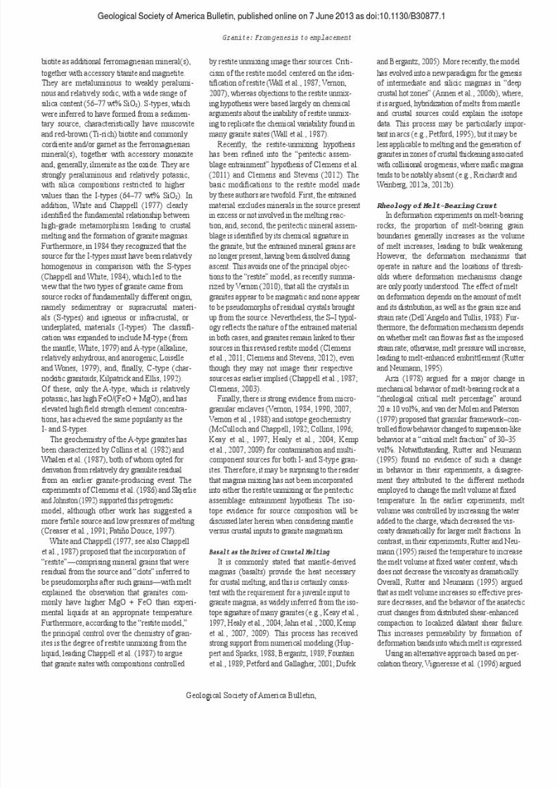
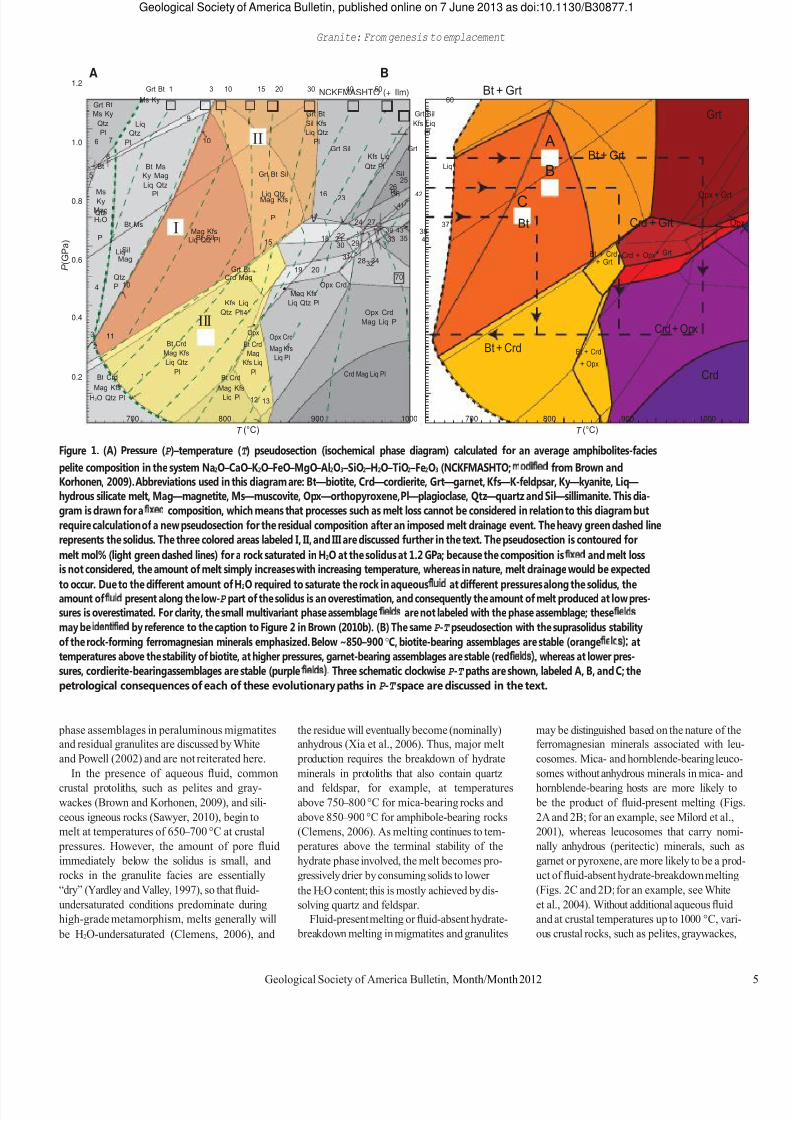
levels in the crust where melting has occurred, from which melt has drained, in which melt has accumulated, and through which melt has transferred (e.g., Brown, 2001b, 2008). Leuco- somes may have liquid compositions, they may consist of dominantly peritectic minerals, they may have cumulate compositions, or they may have crystallized from fractionated liquids (e.g., Brown, 2001b; Solar and Brown, 2001a). Figure 1 is a calculated pressure P -T pseudo-
section (isochemical phase diagram) for an average amphibolites-facies pelite composition in the chemical system Na2O – CaO – K 2O – FeO – MgO – Al2O3 – SiO2 – H2O – TiO2 – Fe2O3 (NCKF- MASHTO; modified from Brown and Korho- nen, 2009). Abbreviations used in this diagram are: Bt — biotite, Crd — cordierite, Grt — garnet, Kfs — K-feldpsar, Ky — kyanite, Liq — hydrous silicate melt, Mag — magnetite, Ms — musco- vite, Opx — orthopyroxene, Pl — plagioclase, Qtz — quartz and Sil — sillimanite. This phase diagram may be used to investigate the process of melting for an undrained system (Brown and Korhonen, 2009). The effects of melt loss on the formation and preservation of suprasolidus
4 Geological Society of America Bulletin, Month/Month 2012
7/27/2019 Brown 2013 Granites Review
http://slidepdf.com/reader/full/brown-2013-granites-review 6/37
P ( G P a )
9 Liq
Qtz II 10 Pl
Bt Ms Sil 5 Ky Mag
Liq Qtz Ms Pl
Pl Mag Kfs Ky Mag H2O 24 27 Pl
I 39 43 22 Pl Bt Sil
15 29 Sil
28 34 Mag 19 20
Qtz 70 Pl 4
Kfs Liq Qtz Pl Opx Crd
Mag Liq Pl
NCKFMASHTO (+ Ilm)
Geological Society of America Bulletin, published online on 7 June 2013 as doi:10.1130/B30877.1 Granite: From genesis to emplacement
1.2
1.0
0.8
0.6
A B Grt Bt 1 3 10 15 20 30 40 50
Ms Ky 60 Grt Bt Ms Ky Grt Bt Grt Sil
Qtz Sil Kfs Kfs Liq Pl Liq Qtz Pl
6 7 Pl Grt Sil Grt
8 Kfs Liq Bt Qtz Pl Liq
Grt Bt Sil 25
26 Liq Qtz 16 36 42 23 41
Qtz 17
Bt Ms 37 Mag Kfs 38
Liq Qtz Pl 18 21 33 35 40 30
Liq 31
32 Grt Bt
Crd Mag 10 Opx Crd
Mag Kfs Liq Qtz Pl
Bt + Grt
C Bt
A B Bt + Grt
Crd + Grt Bt + Crd Crd + Opx+ Grt + Grt
Grt
Opx + Grt Opx
0.4 3 2 11
Bt Crd Mag Kfs Liq Qtz
III 14 Opx
Bt Crd Mag
Kfs Liq Opx Crd Mag Kfs Liq Pl Bt + Crd Bt + Crd
+ Opx Crd + Opx
0.2 Bt Crd 1 Pl Bt Crd Pl Crd Mag Liq Pl Crd
Mag Kfs Mag Kfs H2O Qtz Pl Liq Pl 12 13
700 800 900 1000 T (°C) 700 800 900 1000
T (°C) Figure 1. (A) Pressure (P )–temperature (T ) pseudosection (isochemical phase diagram) calculated for an average amphibolites-facies pelite composition in the system Na2O–CaO–K 2O–FeO–MgO–Al2O3–SiO2–H2O–TiO2–Fe2O3 (NCKFMASHTO; modified from Brown and Korhonen, 2009). Abbreviations used in this diagram are: Bt—biotite, Crd—cordierite, Grt—garnet, Kfs—K-feldpsar, Ky—kyanite, Liq— hydrous silicate melt, Mag—magnetite, Ms—muscovite, Opx—orthopyroxene, Pl—plagioclase, Qtz—quartz and Sil—sillimanite. This dia- gram is drawn for a fixed composition, which means that processes such as melt loss cannot be considered in relation to this diagram but require calculation of a new pseudosection for the residual composition after an imposed melt drainage event. The heavy green dashed line represents the solidus. The three colored areas labeled I, II, and III are discussed further in the text. The pseudosection is contoured for melt mol% (light green dashed lines) for a rock saturated in H2O at the solidus at 1.2 GPa; because the composition is fixed and melt loss is not considered, the amount of melt simply increases with increasing temperature, whereas in nature, melt drainage would be expected to
occur.
Due
to
the
different
amount
of
H2O
required
to
saturate
the
rock
in
aqueous
fluid
at
different
pressures
along
the
solidus,
the
amount of fluid present along the low-P part of the solidus is an overestimation, and consequently the amount of melt produced at low pres- sures is overestimated. For clarity, the small multivariant phase assemblage fields are not labeled with the phase assemblage; these fields may be identified by reference to the caption to Figure 2 in Brown (2010b). (B) The same P -T pseudosection with the suprasolidus stability of the rock-forming ferromagnesian minerals emphasized. Below ~850–900 °C, biotite-bearing assemblages are stable (orange fields); at temperatures above the stability of biotite, at higher pressures, garnet-bearing assemblages are stable (red fields), whereas at lower pres- sures, cordierite-bearing assemblages are stable (purple fields). Three schematic clockwise P -T paths are shown, labeled A, B, and C; the petrological consequences of each of these evolutionary paths in P -T space are discussed in the text. phase assemblages in peraluminous migmatites and residual granulites are discussed by White and Powell (2002) and are not reiterated here. In the presence of aqueous fluid, common
crustal protoliths, such as pelites and gray- wackes (Brown and Korhonen, 2009), and sili- ceous igneous rocks (Sawyer, 2010), begin to melt at temperatures of 650 – 700 °C at crustal pressures. However, the amount of pore fluid immediately below the solidus is small, and rocks in the granulite facies are essentially ―dry‖ (Yardley and Valley, 1997), so that fluid- undersaturated conditions predominate during high-grade metamorphism, melts generally will be H2O-undersaturated (Clemens, 2006), and
the residue will eventually become (nominally) anhydrous (Xia et al., 2006). Thus, major melt production requires the breakdown of hydrate minerals in protoliths that also contain quartz and feldspar, for example, at temperatures above 750 – 800 °C for mica-bearing rocks and above 850 – 900 °C for amphibole-bearing rocks (Clemens, 2006). As melting continues to tem- peratures above the terminal stability of the hydrate phase involved, the melt becomes pro- gressively drier by consuming solids to lower the H2O content; this is mostly achieved by dis- solving quartz and feldspar. Fluid-present melting or fluid-absent hydrate-
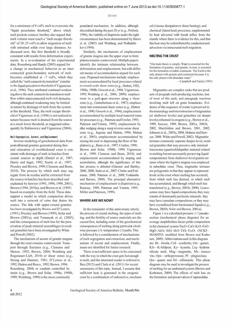
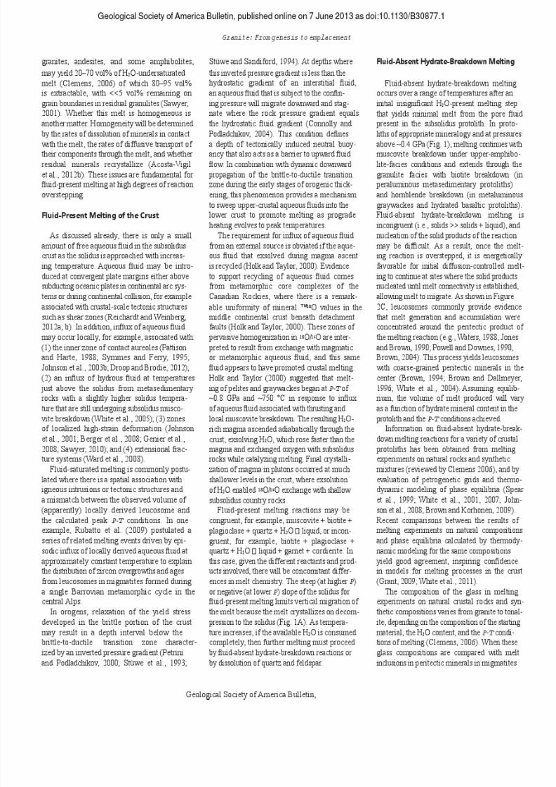
breakdown melting in migmatites and granulites
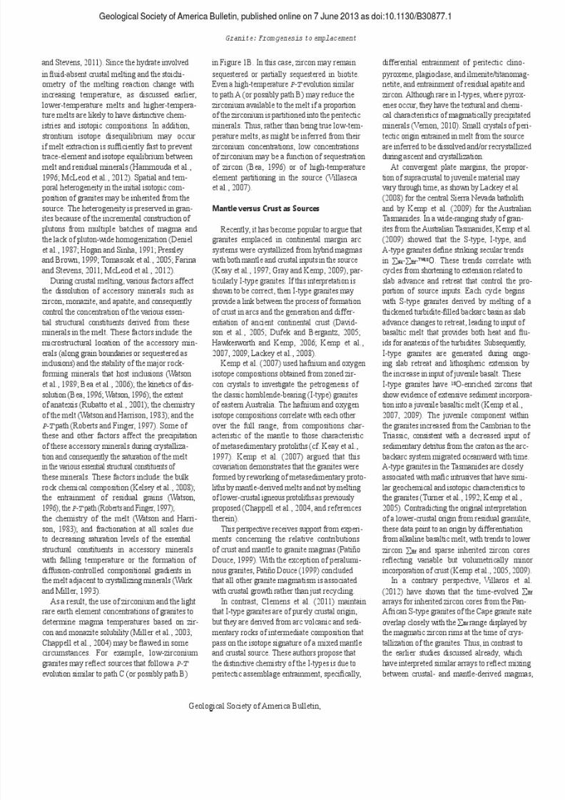
may be distinguished based on the nature of the ferromagnesian minerals associated with leu- cosomes. Mica- and hornblende-bearing leuco- somes without anhydrous minerals in mica- and hornblende-bearing hosts are more likely to be the product of fluid-present melting (Figs. 2A and 2B; for an example, see Milord et al., 2001), whereas leucosomes that carry nomi- nally anhydrous (peritectic) minerals, such as garnet or pyroxene, are more likely to be a prod- uct of fluid-absent hydrate-breakdown melting (Figs. 2C and 2D; for an example, see White et al., 2004). Without additional aqueous fluid and at crustal temperatures up to 1000 °C, vari- ous crustal rocks, such as pelites, graywackes,
Geological Society of America Bulletin, Month/Month 2012 5

7/27/2019 Brown 2013 Granites Review
http://slidepdf.com/reader/full/brown-2013-granites-review 7/37
Geological Society of America Bulletin, published online on 7 June 2013 as doi:10.1130/B30877.1 Brown
A B
Figure 2. Mesoscale features associated with fluid-present (A and B) and fluid-absent hydrate- breakdown (C and D) melting. (A) Stromatic metatexite mig- matite with biotite-rich melano- somes interpreted to have formed by fluid-present melting. Floor of the Guest Hotel foyer at the China University of Geosciences, Wuhan, China; door key card for scale. (B) Patch metatexite migmatite in amphibolite inter- preted to have formed by fluid- present melting; note coarser hornblende crystals associated with the in situ leucosome. From Caishixi in the Taohuayu Geo- heritage Scenic Area, Taishan, Shandong Province, China; hand lens for scale. (C) Stromatic metatexite migmatite (khonda- lite) with pristine peritectic gar- net in the leucosomes indicating loss of melt prior to retrograde C D cooling and final crystallization; this is interpreted to have been a fluid-absent hydrate-breakdown melting event. From Kulappara in the Kerala khondalite belt, southern India; diameter of coin ~20 mm. (D) Mylonitized stro- matic metatexite migmatite (high- pressure granulite) with pristine peritectic garnet associated with the leucosomes indicating loss of melt prior to retrograde cooling and final crystallization; this is interpreted to have been a fluid- absent hydrate-breakdown melt- ing event. From the Lixão quarry in the Três Pontas–Varginha Nappe, southern Brasília belt, Brazil; diameter of coin ~20 mm.
6 Geological Society of America Bulletin, Month/Month 2012
7/27/2019 Brown 2013 Granites Review
http://slidepdf.com/reader/full/brown-2013-granites-review 8/37

7/27/2019 Brown 2013 Granites Review
http://slidepdf.com/reader/full/brown-2013-granites-review 9/37
Geological Society of America Bulletin, published online on 7 June 2013 as doi:10.1130/B30877.1 Brown
and granulites or with the full range of compo- sitions in naturally occurring suites of granite sensu lato, it is clear that a significant portion of the natural compositions cannot be matched with the experimental glass compositions (e.g., Stevens et al., 2007; Cesare et al., 2011; Bar- toli et al., 2013). One explanation for this dis- crepancy
is
that
natural
melts
selectively
entrain
peritectic minerals from the source (Stevens et al., 2007; Clemens et al., 2011; Clemens and Stevens, 2012), and that these entrained min- eral grains are dissolved or achieve equilibrium during ascent through a process of dissolution- reprecipitation cycling in the melt (Villaros et al., 2009a; Taylor and Stevens, 2010). This model receives support from the obser-
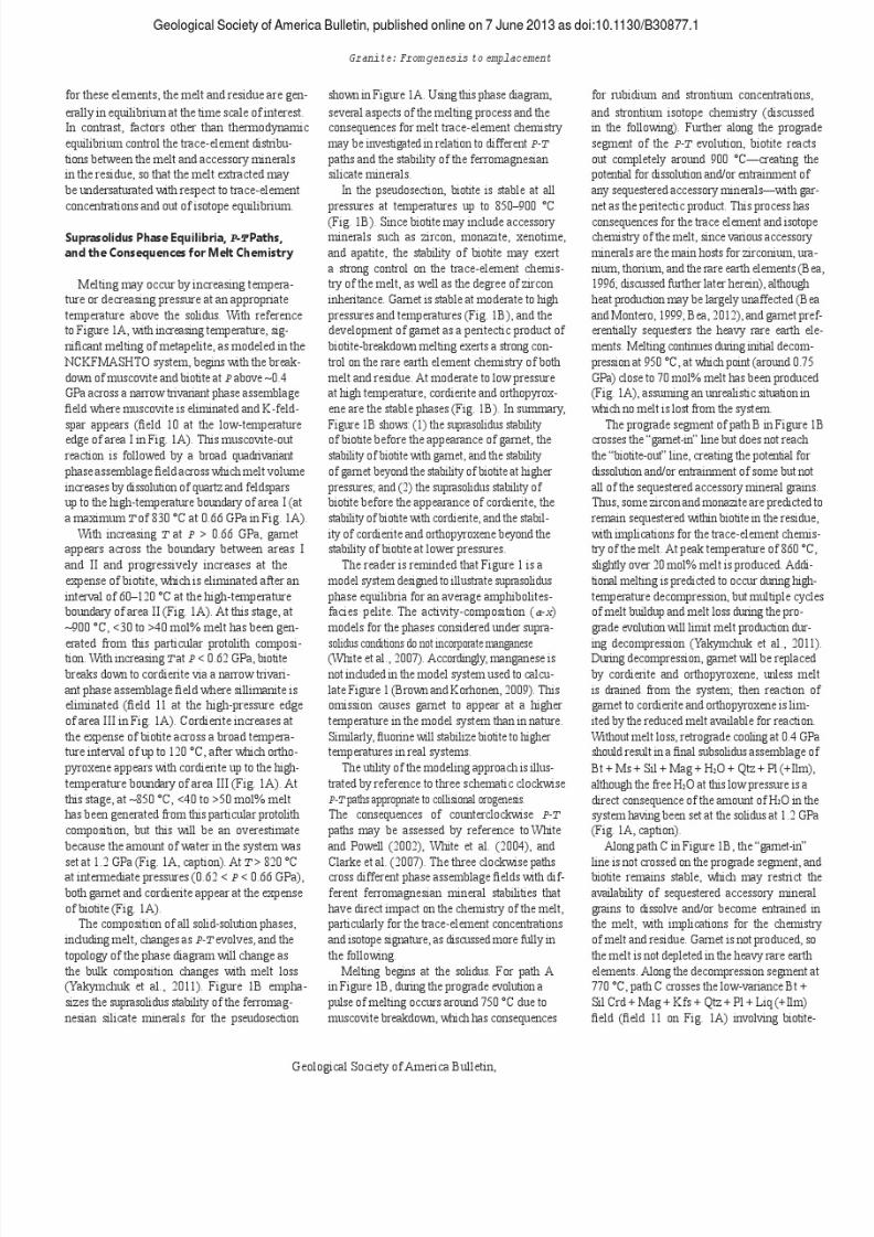
vation in a stromatic migmatite from southern Brittany of garnet within the leucosomes, as imaged using high-resolution computed X-ray tomography, interpreted to be entrained peri- tectic residue trapped during transport (Brown et al., 1999). Many similar examples have now been reported (Fig. 3; e.g., Taylor and Stevens, 2010; Lavaure and Sawyer, 2011), including entrainment of accessory minerals, particularly zircon, from the source (Watson, 1996). Support is also provided by rare enclaves of strongly melt-depleted residue in granite, such as that described by Solar and Brown (2001a), and rare meter-sized pods consisting of 50 – 70 vol% gar- net (with sillimanite, biotite, plagioclase, and quartz), such as those described by Dorais et al. (2009). In the latter example, from the Cardigan pluton in New Hampshire, whole-rock chemis- try
suggests
that
the
garnetites
either
are
restites
or represent melt-depleted xenoliths; similar
neodymium and strontium isotope composition of garnetite and granite, and detailed mineral chemistry reported by Dorais and Tubrett (2012) support an interpretation as restite. Dorais et al. (2009) calculated a magma-ascent rate of >1000 km/yr and proposed that fast ascent inhibited restite dissolution in the Cardigan pluton; they suggested
that
slower
rates
of
ascent
might
account for the paucity of restite preserved in most peraluminous granites. Accessory Minerals Accessory minerals in granites, especially zir-
con, monazite, and apatite, have an importance that far outweighs their modal abundance. Both zircon and monazite potentially may be used to determine the age of crystallization of melt retained in the source and of granite emplaced in the upper crust. In addition, in many gran- ites, inherited grains, particularly forming cores in magmatically-precipitated zircon, preserve information about the source. Accessory miner- als represent a significant reservoir for a number of petrogenetically important trace elements. These elements include zirconium, yttrium, the heavy rare earth elements, hafnium, and ura- nium in zircon, and phosphorus, thorium, and the light rare earth elements in monazite. As a result, the dissolution, entrainment, and crys- tallization of accessory minerals exert a strong control on the trace-element chemistry of gran- ites (Watt and Harley, 1993; Bea, 1996; Watson, 1996; Watt et al., 1996; Bea and Montero, 1999; Brown
et
al.,
1999).
Furthermore,
zircon
and
monazite may be used to estimate the tempera-
ture of crystallization of the granite host (e.g., Watson and Harrison, 1983; Montel, 1993), and the difference between hosts that are rich or poor in inherited zircon has led to a division into ―cold‖ and ―hot‖ granites, respectively (Miller et al., 2003). The trace element and isotope composition
of many
granite
bodies
has
been
interpreted
to
record disequilibrium with respect to refractory accessory minerals in the source (Watt and Harley, 1993; Ayres and Harris, 1997; Jung, 2005; Zeng et al., 2005a, 2005b; Perini et al., 2009; Villaros et al., 2009b; Acosta-Vigil et al., 2012a; McLeod et al., 2012). This feature is sometimes incor- rectly inferred to record ―disequilibrium melting.‖ However, lower-than-expected concentrations of trace elements and isotope disequilibrium may occur for several reasons. These reasons include kinetic effects inhibit-
ing dissolution during melting (Watt and Harley, 1993; Watson, 1996; Watt et al., 1996), non- Henrian behavior during melt-solid partitioning (Bea, 1996), and the sequestration of grains as inclusions in major rock-forming minerals (Bea, 1996; but for a contrary view, see Watson et al., 1989). In general, accessory mineral solubility is a function of temperature and melt composi- tion (Harrison and Watson, 1983, 1984; Rapp and Watson, 1986; Montel, 1993). For example, zircon solubility increases strongly with increas- ing temperature but decreases with increasing silica and aluminum saturation index (Watson and Harrison, 1983; Bea et al., 2006). During crustal melting, it is the major ele-
ments that
determine
the
thermodynamically
stable phase assemblages during melting, and
A B
Figure 3. Examples of peritectic assemblage entrainment consequent upon biotite-breakdown melting and melt migration. (A) Leucosomes in stromatic metatexite migmatite link continuously with thin garnet-bearing, high- aspect-ratio tabular granites. The peritectic garnet decreases in the mode with distance away from the migmatite melanosomes, suggesting limited peritectic assemblage entrainment. From the eastern side of Mount Avers in the central part of the Fosdick migmatite-granite complex, Marie Byrd Land, West Antarctica; handle of ice axe for scale. (B) Local concentrations of peritectic garnet are developed in granite against an enclave of stromatic metatexite migmatite. From the eastern side of Mount Avers in the central part of the Fosdick migmatite-granite complex, Marie Byrd Land, West Antarctica; handle of ice axe for scale.
8 Geological Society of America Bulletin, Month/Month 2012
7/27/2019 Brown 2013 Granites Review
http://slidepdf.com/reader/full/brown-2013-granites-review 10/37
7/27/2019 Brown 2013 Granites Review
http://slidepdf.com/reader/full/brown-2013-granites-review 11/37
7/27/2019 Brown 2013 Granites Review
http://slidepdf.com/reader/full/brown-2013-granites-review 12/37

7/27/2019 Brown 2013 Granites Review
http://slidepdf.com/reader/full/brown-2013-granites-review 13/37
Geological Society of America Bulletin, published online on 7 June 2013 as doi:10.1130/B30877.1 Brown
Villaros et al. (2012) argued that these arrays may be wholly inherited from the source, reflecting mixing among various crustal materi- als of different ages with original hafnium iso- tope compositions. This interpretation supports the original view of S-type granites, i.e., that they inherit their chemical characteristics from the
source.
If
this
interpretation
is
correct,
it
pro-
vides strong support for the hypothesis that peri- tectic assemblage entrainment is the primary mechanism by which granite magmas acquire compositions more mafic than the range defined by the compositions of crustal melts (Clemens and Stevens, 2012). An additional example of polyphase crustal
reworking largely without any juvenile input is provided by the Fosdick migmatite-granite complex of West Antarctica, which preserves evidence of two crustal differentiation events along a segment of the former active margin of Gondwana, one in the Devonian – Carbonifer- ous and another in the Cretaceous (Korhonen et al., 2010a, 2010b, 2012). The Hf-O isotope composition of zircons from Devonian – Car- boniferous granites is explained by mixing of material from two crustal sources consistent with the high-grade metamorphosed equivalents of a Lower Paleozoic turbidite sequence and a Devonian calc-alkaline plutonic suite without input from a more juvenile source (Yakym- chuk et al., 2013b). In contrast, the Hf-O iso- tope composition of zircons from Cretaceous granites requires a contribution from a more juvenile source in addition to contributions from
the
high-grade
metamorphosed
equiva-
lents of the turbidite sequence and the Devonian calc-alkaline plutonic suite (Yakymchuk et al., 2013b). The Fosdick complex granites contrast with coeval granites in other localities along and across the former active margin of Gondwana, including the Tasmanides of Australia and the Western Province of New Zealand, where the wider range of more radiogenic Hf values of zircon suggests that juvenile material played a larger role in granite genesis. This suggests arc- parallel and arc-normal variations in the propor- tion of crustal reworking versus crustal growth along the former active margin of Gondwana (Yakymchuk et al., 2013b). CURRENT VIEWS ON MELT SEGREGATION AND EXTRACTION In several studies, the size-frequency dis-
tributions and spacing of plutons show power- law distributions; these distributions have been used to argue that magmatic systems are self- organized from the bottom up (Bons and Elburg, 2001; Cruden and McCaffrey, 2001; Cruden, 2006; Koukouvelas et al., 2006). This view is
consistent with multiple studies of relict anatec- tic systems (Brown and Solar, 1998a; Brown, 2005, 2010a; Hall and Kisters, 2012; Yakym- chuk et al., 2012) and results from modeling (Petford and Koenders, 1998; Bons and van Milligen, 2001; Ablay et al., 2008; Hobbs and Ord, 2010) that suggest melt extraction may be a self-organized
critical
phenomenon.
The formation of upper-crustal plutons
requires that melt be generated and separated from solid residue within lower-crustal sources and then become focused into high-permeability ascent conduits to feed the roots of plutons. This mass transfer involves a multitude of physical and chemical processes that operate at several different length and time scales linked by feed- back relations between melting and deformation (Brown, 2010a). However, the rheology of crust composed of two distinct but interacting phases, a stiffer solid matrix that hosts a weaker liquid, is complex. Evaluating this rheology is made difficult by the dramatic change in strength that occurs as melting progresses, the dependence of strength on grain-scale distribution of the melt, and the melt pressure, which will be at or close to lithostatic.As a result, actively melting crust is a highly dynamic nonlinear system with history- and time-dependent behavior, characterized by changes in deformation mechanism and redis- tribution of melt by two-phase flow (Vigneresse, 2004; Rosenberg and Handy, 2005; Walte et al., 2005; Rutter and Mecklenburgh, 2006; Závada et al., 2007; Schulmann et al., 2008). If this interpretation of anatectic systems
is accepted,
then
effect
is
fed
back
to
cause,
which may be negative, tending to stabilize the system, or positive, leading to instability. This nonlinear behavior leads to unpredictability, which is expressed in anatectic systems by melt- extraction events. Random fluctuations drive the self-organization of anatectic systems, allowing them to explore new structures while attempting to find the preferred structure (the ―attractor‖). Over time, these fluctuations permit the anatectic system to approach a point at which the prop- erties change suddenly (the critical point) and to maintain itself at that point (e.g., where the matrix in a dynamic system goes from nonperco- lating [disconnected] to percolating [connected] or vice versa). This property is called self-orga- nized criticality. If it is assumed that an anatectic system can mutate, then the system may change toward a more static or a more changeable con- figuration. If the configuration is too static, a more changeable configuration will be selected, and vice versa, until a particular dynamic struc- ture that is optimal for the system is achieved. Thus, anatectic systems adapt to converge on the optimal structure for melt extraction (Brown, 2010a; Hobbs and Ord, 2010).
Inferences from Residual Migmatites and Granulites Pseudomorphs of melt-filled pores in mig-
matites (Holness and Sawyer, 2008) are consis- tent with pervasive melt flow at the grain scale. Similar to texturally equilibrated rocks, melt is inferred
to
flow
along
three-grain
edges,
where
the geometry of the conductive channels is con- trolled by the wetting relations between solid and liquid phases (Laporte et al., 1997), or along individual grain boundaries if these dilate under tectonic stresses (Schulmann et al., 2008). At outcrop scale, leucosome distribution
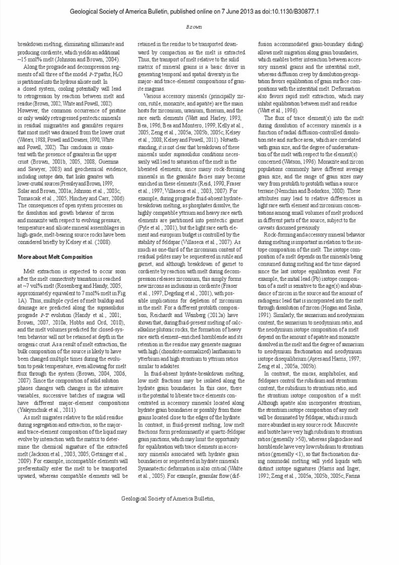
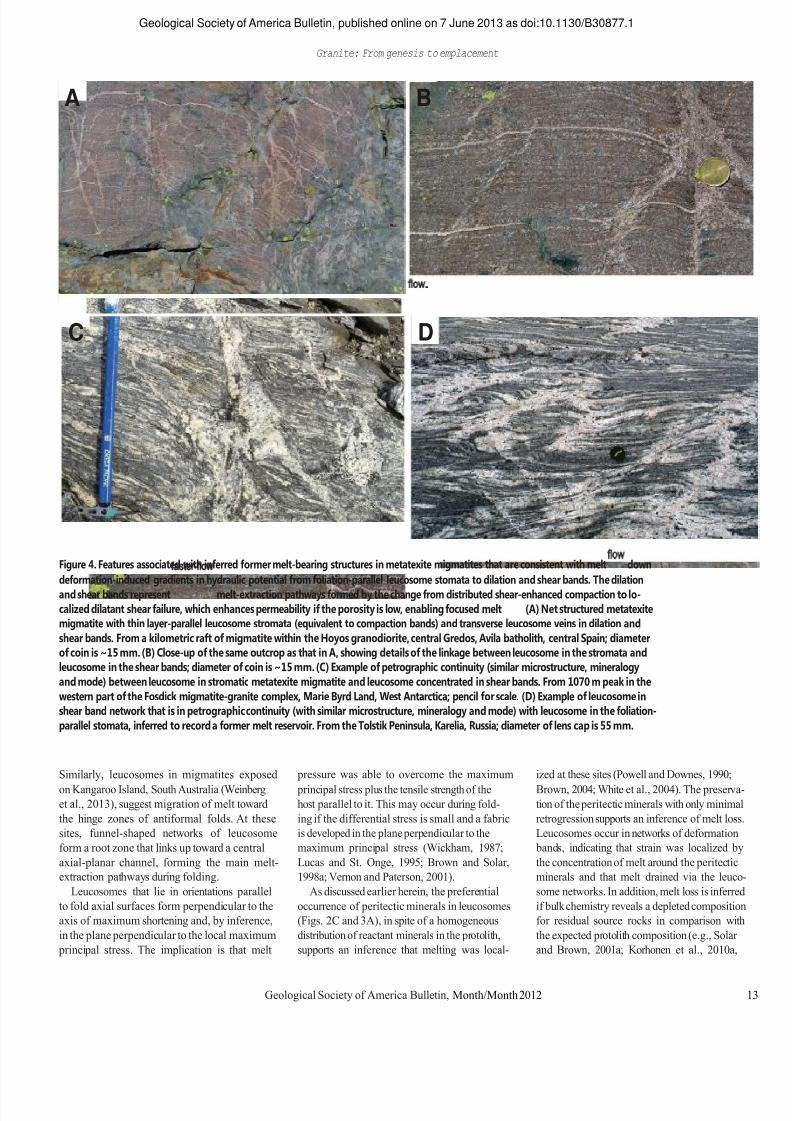
records the interplay between deformation and mesoscale migration of melt, and it provides information about the minimum permeability of the anatectic zone (Tanner, 1999; Sawyer, 2001; Marchildon and Brown, 2002, 2003; Guernina and Sawyer, 2003; Brown, 2004, 2010a). Although not ubiquitous at all leucosome inter- sections, for reasons related to the origin of the leucosomes (peritectic vs. cumulate vs. liquid) and the mechanism of crystallization (cooling vs. diffusive loss of H2O), petrographic con- tinuity (similar modal mineralogy, grain size, and microstructure) between concordant and discordant leucosomes, as shown in Figure 4, is a common occurrence that has been reported in multiple studies (Maaløe, 1992; Brown, 1994, 2004, 2006; Oliver and Barr, 1997; Marchildon and Brown, 2001, 2002, 2003; Sawyer, 2001; Guernina and Sawyer, 2003; Weinberg and Mark, 2008; Hall and Kisters, 2012). Based on this
robust
observation,
networks
of
leucosome-
filled deformation bands in migmatites are inferred to be evidence of the former active melt flow networks in the suprasolidus crust (Jones and Brown, 1990; Allibone and Norris, 1992; Brown, 1994, 2001a, 2001b, 2004, 2005, 2006, 2010a; Collins and Sawyer, 1996; Oliver and Barr, 1997; Sawyer, 1998, 2001; Brown et al., 1999; Sawyer et al., 1999; Daczko et al., 2001; Guernina and Sawyer, 2003; Marchildon and Brown, 2003; White et al., 2004; Weinberg and Mark, 2008; Hall and Kisters, 2012; Yakym- chuk et al., 2012). In the Karakoram shear zone, Weinberg and
Mark (2008) have shown that melt migrated from grain boundaries to layer-parallel leuco- somes in stromatic metatexite migmatite, and then to the axial surfaces of developing folds, where intersecting leucosomes formed pipe-like ―backbone‖ structures for faster flow parallel to the fold hinge lines. Synchronous folding and melt migration led to layer disaggregation, transposition, and the formation of diatexite migmatites, demonstrating that melt migration was an integral part of the accommodation of strain (Weinberg and Mark, 2008, their fig. 15).
12 Geological Society of America Bulletin, Month/Month 2012
7/27/2019 Brown 2013 Granites Review
http://slidepdf.com/reader/full/brown-2013-granites-review 14/37
Geological Society of America Bulletin, published online on 7 June 2013 as doi:10.1130/B30877.1 Granite: From genesis to emplacement
A B
C D
Figure 4. Features associated with inferred former melt-bearing structures in metatexite migmatites that are consistent with melt flow down deformation-induced gradients in hydraulic potential from foliation-parallel leucosome stomata to dilation and shear bands. The dilation and shear bands represent faster-flow melt-extraction pathways formed by the change from distributed shear-enhanced compaction to lo- calized dilatant shear failure, which enhances permeability if the porosity is low, enabling focused melt flow. (A) Net structured metatexite migmatite with thin layer-parallel leucosome stromata (equivalent to compaction bands) and transverse leucosome veins in dilation and shear bands. From a kilometric raft of migmatite within the Hoyos granodiorite, central Gredos, Avila batholith, central Spain; diameter of coin is ~15 mm. (B) Close-up of the same outcrop as that in A, showing details of the linkage between leucosome in the stromata and leucosome in the shear bands; diameter of coin is ~15 mm. (C) Example of petrographic continuity (similar microstructure, mineralogy and mode) between leucosome in stromatic metatexite migmatite and leucosome concentrated in shear bands. From 1070 m peak in the western part of the Fosdick migmatite-granite complex, Marie Byrd Land, West Antarctica; pencil for scale. (D) Example of leucosome in shear band network that is in petrographic continuity (with similar microstructure, mineralogy and mode) with leucosome in the foliation- parallel stomata, inferred to record a former melt reservoir. From the Tolstik Peninsula, Karelia, Russia; diameter of lens cap is 55 mm.
Similarly, leucosomes in migmatites exposed on Kangaroo Island, South Australia (Weinberg et al., 2013), suggest migration of melt toward the hinge zones of antiformal folds. At these sites, funnel-shaped networks of leucosome form a root zone that links up toward a central axial-planar channel, forming the main melt- extraction pathways during folding. Leucosomes that lie in orientations parallel
to fold axial surfaces form perpendicular to the axis of maximum shortening and, by inference, in the plane perpendicular to the local maximum principal stress. The implication is that melt
pressure was able to overcome the maximum principal stress plus the tensile strength of the host parallel to it. This may occur during fold- ing if the differential stress is small and a fabric is developed in the plane perpendicular to the maximum principal stress (Wickham, 1987; Lucas and St. Onge, 1995; Brown and Solar, 1998a; Vernon and Paterson, 2001). As discussed earlier herein, the preferential
occurrence of peritectic minerals in leucosomes (Figs. 2C and 3A), in spite of a homogeneous distribution of reactant minerals in the protolith, supports an inference that melting was local-
ized at these sites (Powell and Downes, 1990; Brown, 2004; White et al., 2004). The preserva- tion of the peritectic minerals with only minimal retrogression supports an inference of melt loss. Leucosomes occur in networks of deformation bands, indicating that strain was localized by the concentration of melt around the peritectic minerals and that melt drained via the leuco- some networks. In addition, melt loss is inferred if bulk chemistry reveals a depleted composition for residual source rocks in comparison with the expected protolith composition (e.g., Solar and Brown, 2001a; Korhonen et al., 2010a,
Geological Society of America Bulletin, Month/Month 2012 13
7/27/2019 Brown 2013 Granites Review
http://slidepdf.com/reader/full/brown-2013-granites-review 15/37
Geological Society of America Bulletin, published online on 7 June 2013 as doi:10.1130/B30877.1 Brown
2010b), and it is also implied by the formation of collapse structures (Bons et al., 2008). Never- theless, net melt loss estimated qualitatively based on this type of evidence is a minimum, since residual migmatites and granulites pre- serve an integrated record of melt flux through the anatectic zone (Brown, 2004; Olsen et al., 2004;
Slagstad
et
al.,
2005;
Korhonen
et
al.,
2010a, 2010b). One consequence of melt flux is that leuco-
somes are rarely primary liquid compositions; commonly, they are of two types. In the first type, the compositions exhibit strong positive euro- pium anomalies and low zirconium concentra- tions, features that are expected of leucosomes formed during the early stage of segregation and extraction. Leucosomes of this type rep- resent either early crystallization of feldspars and quartz (Sawyer, 1987; Solar and Brown, 2001a, 2001b; Johnson et al., 2003c, 2012; Korhonen et al., 2010b) or prograde growth and accumulation of peritectic feldspar (together with a ferromagnesian peritectic mineral, such as garnet, and possibly residual quartz) as the result of chemical potential gradients present during melting (White et al., 2004). In the sec- ond type, the compositions show strong nega- tive europium anomalies and high zirconium, features that are expected of leucosomes formed from percolating fractionated melt trapped dur- ing cooling of the terrane (Sawyer, 1987, 1998; Solar and Brown, 2001a, 2001b; Hinchey and Carr, 2006; Korhonen et al., 2010b; White and Powell, 2010). The
contrast
between
cumulate
and
fraction-
ated leucosome compositions is generated as melt migrates because it encounters host rock that is cooler than the liquidus for the melt com- position, which causes crystallization of liquidus minerals (likely feldspar and quartz) on the chan- nel walls. Thus, there is a continuous process of crystallization and liquid fractionation during extraction until the evolved melt crosses the anatectic front, after which, if the evolved liquid is of sufficient volume, it ascends to an upper- crustal pluton. Additional complexity in leucosome com-
positions arises where hybridization of melts from different protoliths occurs in the source or a leucosome network is reused multiple times. For example, Reichardt et al. (2010) described leucosomes that root in different protoliths, merging with each other and homogenizing as they link up to form a hierarchy of channels, feeding into stocks, plutons, and ultimately into the Karakoram batholith. This interpretation is supported by the hybrid isotope signature of leucosomes, which is intermediate between the protolith signatures, and their similarity to intru- sive granites. Thus, the leucosomes represent
part of a complex melt flow network indicative of large-scale interconnectivity. The hybrid iso- tope signature is interpreted to result from local equilibration by microscale interaction between new melt batches and previously crystallized magmatic rocks as melt migrated via grain boundaries along an S-C fabric related to syn- anatectic
deformation
rather
than
any
mixing
among melt batches (Hasalová et al., 2011). The features of leucosomes described here
are strong evidence that residual source rocks were both zones of melt generation and zones of melt transfer (Brown, 2004, 2006, 2007; Olsen et al., 2004; Korhonen et al., 2010a, 2010b). Formation of Melt Flow Networks Under equilibrium conditions in isotropic
crust, melting begins at multiphase grain junc- tions that include quartz and feldspar, and com- monly a hydrate mineral. However, Earth‘s crust is anisotropic and in a state of stress, with variations in bulk composition and grain size that influence sites where melting begins and where melt accumulates. Fluid-absent hydrate- breakdown melting commonly begins at sites of lower pressure, once the initial thermal overstep is close to that required to overcome the acti- vation energy for a particular melting reaction (Brown and Solar, 1998a). The source becomes permeable at the melt
connectivity transition, and melt extraction may occur if the solid residue is able to deform and compact (Rabinowicz and Vigneresse, 2004; Rutter
and
Mecklenburgh,
2006).
With
increas-
ing melt volume, the effective mean stress decreases, and the behavior of the anatectic crust may change from distributed shear-enhanced compaction, which reduces permeability, to localized dilatant shear failure, which enhances permeability if the porosity is low (Rutter, 1997; Rutter and Mecklenburgh, 2006). Thus, focused melt flow requires dilatant shear failure at low melt fractions, consistent with the melt connec- tivity transition of Rosenberg and Handy (2005) and the concept of a melt segregation window as proposed by Rabinowicz and Vigneresse (2004).
Fabric-parallel compaction bands may form in anisotropic rocks as pockets of melt become overpressured and fail by loss of cohesion at grain boundaries and injection of melt along these boundaries, or by a cavitation-driven dila- tion process, or by propagation of ductile frac- tures. Formation of compaction bands during early, distributed shear-enhanced compaction implies a flow law that permits localization in the strain-hardening regime (Sheldon et al., 2006). As the melt fraction reaches the melt connectivity transition, the change to localized dilatant shear failure enables melt to move from
compaction bands into shear bands (oblique to fabric) and dilation bands (generally fabric- normal) as determined by gradients in hydraulic potential (van der Molen, 1985; Maaløe, 1992; Brown et al., 1995; Brown and Rushmer, 1997; Sawyer, 2001; Guernina and Sawyer, 2003). This process leads to the formation of outcrop- scale
melt-filled
deformation
band
networks,
as
evidenced by leucosome networks in residual crust (Figs. 3A and 4). Thus, a continuous link for melt flow from
pores to vein networks may be created, produc- ing a system that cycles between melt accu- mulation and melt loss, where this process is modulated by the rate of melt production and the deformation-induced pressure gradients driving the melt flow from grain boundaries to vein networks. The way in which these vein networks connect to ascent conduits where melt ascent is driven by buoyancy remains enig- matic, although theoretical and phenomeno- logical models have been proposed (Clemens and Mawer, 1992; Petford and Koenders, 1998; Brown and Solar, 1999; Weinberg, 1999; Bons et al., 2001, 2004; Leitch and Weinberg, 2002; Brown, 2004; Ablay et al., 2008; Hobbs and Ord, 2010). Focusing Melt for Extraction Fertile crustal rocks have the potential to
yield a variable amount of melt at the meta- morphic peak, according to the compositional balance, and so source volumes may vary from about
ten
times
to
only
two
times
the
volume
of a pluton, according to the crustal temperature achieved (Brown, 2001a, 2001b). Ultimately, melt drains from the source via a limited num- ber of discrete tabular or cylindrical conduits to feed upper-crustal plutons (Vigneresse, 1988; Brown and Solar, 1998b; Vigneresse et al., 1999; Cruden, 2006). The common association of middle-crustal
migmatites with outcrop-scale bodies of gran- ite suggests that regional-scale migmatite- granite complexes preserve an integrated record of melt generation, melt loss, melt pas- sage, and melt entrapment. As such, they rep- resent the upper levels of the anatectic zone through which fugitive magma was transferred from deeper in the source to accumulate in plutons in the shallower crust (e.g., Brown and Solar, 1999; Brown, 2004, 2005; Olsen et al., 2004; Slagstad et al., 2005; Korhonen et al., 2010a, 2010b; Morfin et al., 2013). In the source, a critical point may be reached at some combination of melt fraction and distribution that enables formation of conduits of a size that allows melt to be extracted episodically. For this to occur, it is likely that the melt volume
14 Geological Society of America Bulletin, Month/Month 2012

7/27/2019 Brown 2013 Granites Review
http://slidepdf.com/reader/full/brown-2013-granites-review 16/37
5 – 1 5 k m
2 0 – 5 0 k
m
2 0 – 5 0 k
m
5 – 1 5 k m
Geological Society of America Bulletin, published online on 7 June 2013 as doi:10.1130/B30877.1 Granite: From genesis to emplacement
will be above the melt connectivity transi- tion at ~7 vol% melt and that a melt-bearing network of deformation bands will have been formed (Brown, 2004, 2010a). The anatectic front — equivalent to the solidus
and representing the upper surface of the melt- bearing source, a dynamic feature during oro- genesis
(Brown
and
Solar,
1999) — is
recorded
in orogenic crust by the first appearance of leucosome, corresponding to the fluid-present solidus. The height from the anatectic front to the level of emplacement varies according to the
A B QEm
QAs QEx
tectonic setting, the degree of orogenic thicken- ing, and the amount of subsequent extension or collapse. Along an active continental margin, the distance separating the granite source from the site of melt accumulation is rarely going to be more than 30 km and commonly will be less, and the thickness of the source is likely to be <20 km; this is shown schematically in Figure 5A. In Figure 5B, melt has been drained from the source, and a pluton has been emplaced at the level of the ductile-to-brittle transition zone. The rates of melt production (not shown in Fig. 5B), extraction (Q Ex), ascent (Q As), and emplacement (Q Em) are assumed to be balanced
Figure 5. Schematic diagram to illustrate melt extraction, ascent, and emplacement along an active continental margin (based on a model in Cruden, 1998). (A) Segregated melt in the suprasolidus source, shown schematically in red, is located in fabric-parallel stromata and thin sills prior to formation of dikes to allow ascent. (B) After melt ascent, a pluton has formed at the level of the ductile-to-brittle transition zone, with space being made by a combination of lifting of the roof and depression of the floor, accommodated by volume loss in the source due to efflux of the melt. The rates of melt production (not shown on dia- gram), extraction (Q Ex), ascent (Q As), and emplacement (Q Em) are assumed to be balanced at the crustal scale. The depths shown on the right-hand side of the figures are intended as a general indication of the likely range along an active continental margin. As a consequence of melt extraction, the source is less fertile and more residual.
at the crustal scale by various feedback relations (Cruden, 1998; Brown, 2004, 2010a; Hobbs and Ord, 2010). The spacing of plutons in formerly active
continental margins and collisional orogens (Bons and Elburg, 2001; Cruden, 2006) strongly suggests that ascent is spatially focused, and the spacing of plutons likely reflects the footprint of the
source
being
drained
beneath
them
(Fig.
6).
Since there are only a small number of feeders to an individual pluton, and the footprint of the source that is drained for any single pluton is unlikely to be smaller than the lateral extent of the granite, as illustrated schematically in Fig- ure 6, the principal unresolved issue in melt extraction is focusing the melt flow to the ascent conduit(s). There are several ways by which focused
flow of melt to ascent conduits may be achieved. Where lower-crustal fabrics are shallow, and, therefore, the anisotropy of permeability is shal- low, melt flow down hydraulic potential gra- dients to ascent conduits or major shear zones is commonly postulated (e.g., Brown, 2005, 2006; Rosenberg, 2004), and may be driven by gravitational potential due to differences in topographic relief (Hobbs and Ord, 2010). The effect of applied differential stress is limited by the flow strength of melt-bearing crust (Rutter and Mecklenburgh, 2006). Nonetheless, if the hydraulic potential gradient is maximized, such as at low melt fractions in crust with contrasting lithologies that create an extrinsic anisotropy of permeability to channel flow along particular
layers with strong intrinsic anisotropy of perme- ability, then lateral melt flow driven by defor- mation may be kilometric (Hobbs and Ord, 2010, their table 2). In circumstances where the tectonic fabrics are steep, fabric anisotropies are expected to control extraction of melt, with the form of the magma-ascent conduits mim- icking the apparent finite strain (Fig. 7; Brown and
Solar,
1998a,
1998b,
1999;
Weinberg
et
al.,
2009; Marcotte et al., 2005). Since the solidus surface is a dynamic fea-
ture in three dimensions during orogenic defor- mation (Brown and Solar, 1999), the anatectic zone expands upward as the solidus surface is displaced to shallower crustal levels during the prograde metamorphic evolution, but it con- tracts downward during the retrograde stage. Given regional-scale variations in strain along the length of an orogen, it is likely that the soli- dus surface in three dimensions is uneven and undulating, with antiformal culminations and synformal troughs. Under these circumstances, the solidus surface may act as a melt-imper- meable boundary, or permeability barrier, at the base of the subsolidus crust, analogous to models for melt extraction at mid-ocean ridges (Sparks and Parmentier, 1991; Gregg et al., 2012). Although such a permeability barrier must inevitably be associated with a crystalliza- tion front at the solidus, the uneven and undulat- ing nature of the front may allow melt to migrate upslope, driven by buoyancy, to points of melt extraction that form at antiformal culminations in the solidus surface. Melt accumulates at these
points of melt extraction until the volume is suf- ficient to allow it to ascend by buoyancy to the level of pluton emplacement. The size and spac- ing of plutons will be determined by the location of these melt-extraction points (Fig. 6; Brown and Solar, 1999). Lower-crustal melting driven by heat supply
is a continuous process. In contrast, melt extrac- tion
is
a discontinuous
process
that
is
cyclic
(e.g., Brown and Solar, 1998a; Handy et al., 2001; Rabinowicz and Vigneresse, 2004). The switch from a continuous to a discontinuous process is fundamental and has been discussed before (Brown and Solar, 1998a; Handy et al., 2001); it is a consequence of the nonlinear feed- back relations during melting (Brown, 2010a; Hobbs and Ord, 2010). CURRENT VIEWS ON MAGMA ASCENT AND EMPLACEMENT Leucosome networks and mesoscale pods of
diatexite, migmatite, and granite within residual host rocks provide evidence of the storage sys- tem for melt accumulation prior to extraction. The storage networks and locally ponded melt feed the ascent conduits that transport magma to shallower levels in the crust (Brown, 1994; Sawyer, 1998; Brown, 2004, 2006, 2007, 2010a; Reichardt and Weinberg, 2012a). In general, plutons are constructed incremen-
tally (e.g., Deniel et al., 1987; Brown and Solar, 1999; Pressley and Brown, 1999; Miller, 2008; Clemens and Benn, 2010), consistent with
Geological Society of America Bulletin, Month/Month 2012 15
7/27/2019 Brown 2013 Granites Review
http://slidepdf.com/reader/full/brown-2013-granites-review 17/37
Geological Society of America Bulletin, published online on 7 June 2013 as doi:10.1130/B30877.1 Brown
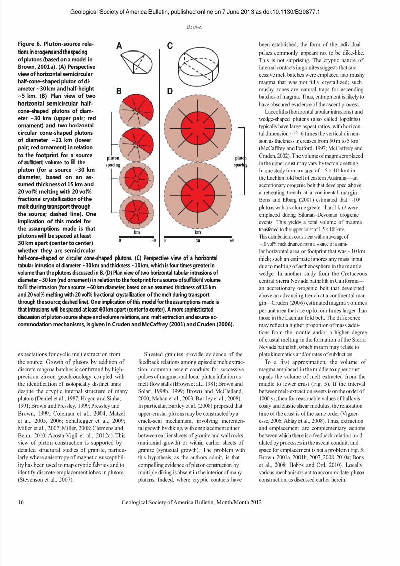
Figure 6. Pluton-source rela- tions in orogens and the spacing of plutons (based on a model in Brown, 2001a). (A) Perspective view of horizontal semicircular half-cone–shaped pluton of di- ameter ~30 km and half-height ~5
km.
(B)
Plan
view
of
two
horizontal semicircular half- cone–shaped plutons of diam- eter ~30 km (upper pair; red ornament) and two horizontal circular cone-shaped plutons of diameter ~21 km (lower pair; red ornament) in relation
A C
B D
been established, the form of the individual pulses commonly appears not to be dike-like. This is not surprising. The cryptic nature of internal contacts in granites suggests that suc- cessive melt batches were emplaced into mushy magma that was not fully crystallized; such mushy zones are natural traps for ascending batches
of
magma.
Thus,
entrapment
is
likely
to
have obscured evidence of the ascent process. Laccoliths (horizontal tabular intrusions) and
wedge-shaped plutons (also called lopoliths) typically have large aspect ratios, with horizon- tal dimension ~12 – 6 times the vertical dimen- sion as thickness increases from 50 m to 5 km (McCaffrey and Petford, 1997; McCaffrey and
to the footprint for a source of sufficient volume to fill the pluton (for a source ~30 km diameter, based on an as- sumed thickness of 15 km and 20 vol% melting with 20 vol% fractional crystallization of the melt during transport through the source; dashed line). One implication of this model for
pluton spacing pluton
spacing Cruden, 2002). The volume of magma emplaced in the upper crust may vary by tectonic setting. In one study from an area of 1.5 × 10⁵ km2 in the Lachlan fold belt of eastern Australia — an accretionary orogenic belt that developed above a retreating trench at a continental margin — Bons and Elburg (2001) estimated that ~103 plutons with a volume greater than 1 km3 were emplaced during Silurian – Devonian orogenic events. This yields a total volume of magma
the assumptions made is that plutons will be spaced at least 30 km apart (center to center) 0 km
30 0 km 30 60
transferred to the upper crust of 1.5 × 10⁵ km3. This distribution is consistent with an average of ~10 vol% melt drained from a source of a simi-
whether they are semicircular half-cone–shaped or circular cone-shaped plutons. (C) Perspective view of a horizontal tabular intrusion of diameter ~30 km and thickness ~10 km, which is four times greater in volume than the plutons discussed in B. (D) Plan view of two horizontal tabular intrusions of diameter ~30 km (red ornament) in relation to the footprint for a source of sufficient volume to fill the intrusion (for a source ~60 km diameter, based on an assumed thickness of 15 km and
20
vol%
melting
with
20
vol%
fractional
crystallization
of
the
melt
during
transport
through the source; dashed line). One implication of this model for the assumptions made is that intrusions will be spaced at least 60 km apart (center to center). A more sophisticated discussion of pluton-source shape and volume relations, and melt extraction and source ac- commodation mechanisms, is given in Cruden and McCaffrey (2001) and Cruden (2006).
lar horizontal area or footprint that was ~10 km thick; such an estimate ignores any mass input due to melting of asthenosphere in the mantle wedge. In another study from the Cretaceous central Sierra Nevada batholith in California — an accretionary orogenic belt that developed above
an
advancing
trench
at
a continental
mar-
gin — Cruden (2006) estimated magma volumes per unit area that are up to four times larger than those in the Lachlan fold belt. The difference may reflect a higher proportion of mass addi- tions from the mantle and/or a higher degree of crustal melting in the formation of the Sierra Nevada batholith, which in turn may relate to
expectations for cyclic melt extraction from the source. Growth of plutons by addition of discrete magma batches is confirmed by high- precision zircon geochronology coupled with the identification of isotopically distinct units despite the cryptic internal structure of many plutons (Deniel et al., 1987; Hogan and Sinha, 1991; Brown and Pressley, 1999; Pressley and Brown, 1999; Coleman et al., 2004; Matzel et al., 2005, 2006; Schaltegger et al., 2009; Miller et al., 2007; Miller, 2008; Clemens and Benn, 2010; Acosta-Vigil et al., 2012a). This view of pluton construction is supported by detailed structural studies of granite, particu- larly where anisotropy of magnetic susceptibil- ity has been used to map cryptic fabrics and to identify discrete emplacement lobes in plutons (Stevenson et al., 2007).
Sheeted granites provide evidence of the feedback relations among episodic melt extrac- tion, common ascent conduits for successive pulses of magma, and local pluton inflation as melt flow stalls (Brown et al., 1981; Brown and Solar, 1998b, 1999; Brown and McClelland, 2000; Mahan et al., 2003; Bartley et al., 2008). In particular, Bartley et al. (2008) proposed that upper-crustal plutons may be constructed by a crack-seal mechanism, involving incremen- tal growth by diking, with emplacement either between earlier sheets of granite and wall rocks (antitaxial growth) or within earlier sheets of granite (syntaxial growth). The problem with this hypothesis, as the authors admit, is that compelling evidence of pluton construction by multiple diking is absent in the interior of many plutons. Indeed, where cryptic contacts have
plate kinematics and/or rates of subduction. To a first approximation, the volume of
magma emplaced in the middle to upper crust equals the volume of melt extracted from the middle to lower crust (Fig. 5). If the interval between melt-extraction events is on the order of 1000 yr, then for reasonable values of bulk vis- cosity and elastic shear modulus, the relaxation time of the crust is of the same order (Vigner- esse, 2006; Ablay et al., 2008). Thus, extraction and emplacement are complementary actions between which there is a feedback relation mod- ulated by processes in the ascent conduit, and space for emplacement is not a problem (Fig. 5; Brown, 2001a, 2001b, 2007, 2008, 2010a; Bons et al., 2008; Hobbs and Ord, 2010). Locally, various mechanisms act to accommodate pluton construction, as discussed earlier herein.
16 Geological Society of America Bulletin, Month/Month 2012
7/27/2019 Brown 2013 Granites Review
http://slidepdf.com/reader/full/brown-2013-granites-review 18/37
A C Z
no vertical exaggeration
Geological Society of America Bulletin, published online on 7 June 2013 as doi:10.1130/B30877.1 Granite: From genesis to emplacement
A ACZ ACZ ACZ B to millimetric stromatic leucosomes (Fig. 8B). Close to the tips, these dikelets have an open
CMB rocks M
TAD P WAD BHB
rocks Ki
L L P
zigzag form (Fig. 8B, below the coin) and bifur- cate or splay (Fig. 8A). Similarly, in the southern Brittany migmatite
BHB rocks Ms-breakdown
melting zone belt of western France, centimeter- to meter- scale granite dikes are abundant at outcrop (Fig.
solidus Bt-breakdown undifferentiated crustal rocks melting zone
10 km undifferentiated crustal rocks 8C). Although
the
volumetric
importance
of
the
dikes varies in space, they may represent up to 20% of the area of an outcrop. At outcrop scale,
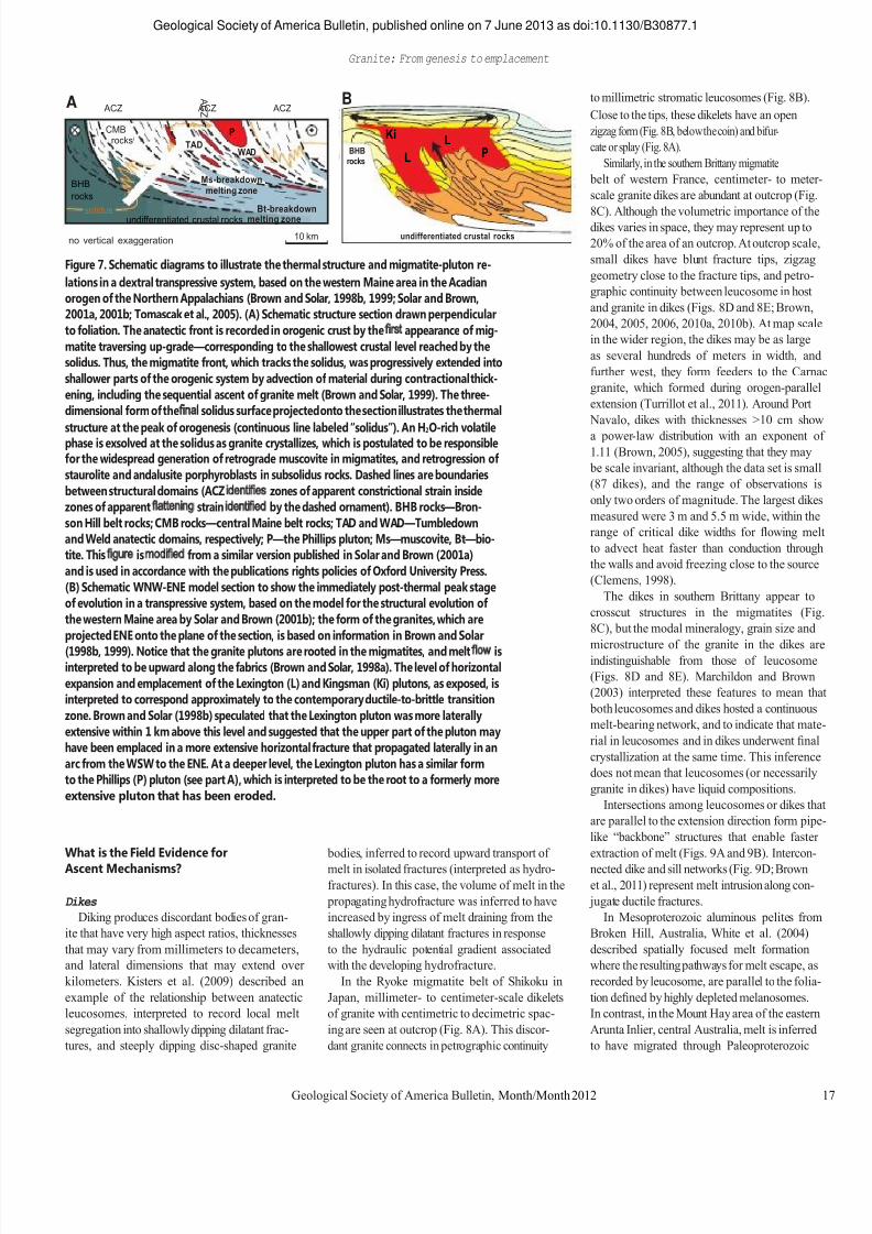
Figure 7. Schematic diagrams to illustrate the thermal structure and migmatite-pluton re- lations in a dextral transpressive system, based on the western Maine area in the Acadian orogen of the Northern Appalachians (Brown and Solar, 1998b, 1999; Solar and Brown, 2001a, 2001b; Tomascak et al., 2005). (A) Schematic structure section drawn perpendicular to foliation. The anatectic front is recorded in orogenic crust by the first appearance of mig- matite traversing up-grade—corresponding to the shallowest crustal level reached by the solidus. Thus, the migmatite front, which tracks the solidus, was progressively extended into shallower parts of the orogenic system by advection of material during contractional thick- ening, including the sequential ascent of granite melt (Brown and Solar, 1999). The three- dimensional form of the final solidus surface projected onto the section illustrates the thermal structure at the peak of orogenesis (continuous line labeled ―solidus‖). An H2O-rich volatile phase is exsolved at the solidus as granite crystallizes, which is postulated to be responsible for the widespread generation of retrograde muscovite in migmatites, and retrogression of staurolite and andalusite porphyroblasts in subsolidus rocks. Dashed lines are boundaries between structural domains (ACZ identifies zones of apparent constrictional strain inside zones of apparent flattening strain identified by the dashed ornament). BHB rocks—Bron- son Hill belt rocks; CMB rocks—central Maine belt rocks; TAD and WAD—Tumbledown and Weld anatectic domains, respectively; P—the Phillips pluton; Ms—muscovite, Bt—bio- tite. This figure is modified from a similar version published in Solar and Brown (2001a) and is used in accordance with the publications rights policies of Oxford University Press. (B) Schematic WNW-ENE model section to show the immediately post-thermal peak stage of evolution in a transpressive system, based on the model for the structural evolution of the western Maine area by Solar and Brown (2001b); the form of the granites, which are projected ENE onto the plane of the section, is based on information in Brown and Solar (1998b, 1999). Notice that the granite plutons are rooted in the migmatites, and melt flow is interpreted to be upward along the fabrics (Brown and Solar, 1998a). The level of horizontal expansion and emplacement of the Lexington (L) and Kingsman (Ki) plutons, as exposed, is interpreted to correspond approximately to the contemporary ductile-to-brittle transition zone. Brown and Solar (1998b) speculated that the Lexington pluton was more laterally extensive within 1 km above this level and suggested that the upper part of the pluton may have been emplaced in a more extensive horizontal fracture that propagated laterally in an arc from the WSW to the ENE. At a deeper level, the Lexington pluton has a similar form to the Phillips (P) pluton (see part A), which is interpreted to be the root to a formerly more extensive pluton that has been eroded.
small dikes have blunt fracture tips, zigzag geometry close to the fracture tips, and petro- graphic continuity between leucosome in host and granite in dikes (Figs. 8D and 8E; Brown, 2004, 2005, 2006, 2010a, 2010b). At map scale in the wider region, the dikes may be as large as several hundreds of meters in width, and further west, they form feeders to the Carnac granite, which formed during orogen-parallel extension (Turrillot et al., 2011). Around Port Navalo, dikes with thicknesses >10 cm show a power-law distribution with an exponent of 1.11 (Brown, 2005), suggesting that they may be scale invariant, although the data set is small (87 dikes), and the range of observations is only two orders of magnitude. The largest dikes measured were 3 m and 5.5 m wide, within the range of critical dike widths for flowing melt to advect heat faster than conduction through the walls and avoid freezing close to the source (Clemens, 1998). The dikes in southern Brittany appear to
crosscut structures in the migmatites (Fig. 8C), but the modal mineralogy, grain size and microstructure
of
the
granite
in
the
dikes
are
indistinguishable from those of leucosome (Figs. 8D and 8E). Marchildon and Brown (2003) interpreted these features to mean that both leucosomes and dikes hosted a continuous melt-bearing network, and to indicate that mate- rial in leucosomes and in dikes underwent final crystallization at the same time. This inference does not mean that leucosomes (or necessarily granite in dikes) have liquid compositions. Intersections among leucosomes or dikes that
are parallel to the extension direction form pipe- like ―backbone‖ structures that enable faster
What is the Field Evidence for Ascent Mechanisms? Dikes Diking produces discordant bodies of gran-
ite that have very high aspect ratios, thicknesses that may vary from millimeters to decameters, and lateral dimensions that may extend over kilometers. Kisters et al. (2009) described an example of the relationship between anatectic leucosomes, interpreted to record local melt segregation into shallowly dipping dilatant frac- tures, and steeply dipping disc-shaped granite
bodies, inferred to record upward transport of melt in isolated fractures (interpreted as hydro- fractures). In this case, the volume of melt in the propagating hydrofracture was inferred to have increased by ingress of melt draining from the shallowly dipping dilatant fractures in response to the hydraulic potential gradient associated with the developing hydrofracture. In the Ryoke migmatite belt of Shikoku in
Japan, millimeter- to centimeter-scale dikelets of granite with centimetric to decimetric spac- ing are seen at outcrop (Fig. 8A). This discor- dant granite connects in petrographic continuity
extraction of melt (Figs. 9A and 9B). Intercon- nected dike and sill networks (Fig. 9D; Brown et al., 2011) represent melt intrusion along con- jugate ductile fractures.
In Mesoproterozoic aluminous pelites from Broken Hill, Australia, White et al. (2004) described spatially focused melt formation where the resulting pathways for melt escape, as recorded by leucosome, are parallel to the folia- tion defined by highly depleted melanosomes. In contrast, in the Mount Hay area of the eastern Arunta Inlier, central Australia, melt is inferred to have migrated through Paleoproterozoic
Geological Society of America Bulletin, Month/Month 2012 17

7/27/2019 Brown 2013 Granites Review
http://slidepdf.com/reader/full/brown-2013-granites-review 19/37
Geological Society of America Bulletin, published online on 7 June 2013 as doi:10.1130/B30877.1 Brown
lower crust via a network of narrow, structur- ally controlled pathways parallel to the mod- erately to steeply plunging regional elongation direction, as evidenced by leucosomes associ- ated with coaxial folds and a strong mineral- elongation lineation (Fig. 10B; Collins and Sawyer, 1996). Concordant Tabular and Cylindrical Granites Structurally concordant tabular or cylindrical
granites, which are also referred to as ―sheets‖ and ―pipes‖ of granite in the literature, with high aspect ratios, thicknesses up to decameters, and lateral dimensions that may extend over kilome- ters, occur in the high-grade parts of many orogenic belts. They are commonly, but not always, associated with host migmatite (Figs. 9C and 10). In the transpressive Acadian belt in the
Northern Appalachians, the form of the inferred magma-ascent conduits mimics the apparent strain ellipsoid recorded by the host-rock fab- rics (Brown and Solar, 1999; Solar and Brown, 2001a). Concordant tabular granites occur in zones of apparent flattening strain (Fig. 10A), whereas concordant cylindrical granites occur in zones of apparent constrictional strain. Overall, the orogen-parallel orientation of the tabular granites demonstrates that magma was transferred in structures oriented at a high angle to the far-field maximum principal stress (Brown and Solar, 1998b, their fig. 7; Solar and Brown, 2001b). A similar relationship between granite in
ascent conduits
and
the
regional
stress
field
is
observed in a variety of tectonic settings. For
Role of Compaction Efficient fluid expulsion from poorly drained
rocks requires a dynamic mechanism in which the dilational deformation responsible for increasing permeability is balanced by a compac- tion mechanism at depth responsible for main- taining
high
fluid
pressure.
An
essential
feature
of such a mechanism is that, irrespective of the mean stress gradient, hydraulic connectivity must be maintained over a vertical interval that is large enough to generate the effective pressures neces- sary to drive the deformation (Connolly and Pod- ladchikov, 2007). Melt distribution in connected porosity in suprasolidus crust may be affected by small-scale variations in mineralogy (Wat- son, 1999), grain size (Wark and Watson, 2000), or grain orientation (Waff and Faul, 1992), and suprasolidus crust is likely to be characterized by nonuniform melt distribution as a result. In these circumstances, porosity waves may nucleate from such small perturbations in the distribution of melt due to a rheological asymmetry between compaction and decompaction in two-phase vis- cous materials (Connolly, 2010; Connolly and Podladchikov, 2007, 2012). The instabilities grow by drawing melt in from the permeable matrix, compacting that part of the source, causing dila- tion, increasing melt volume, and disaggregating the matrix to form a magmatic suspension (Fig. 11). Since flow is enhanced where melt fraction is higher, more melt drains to the instabilities from the background porosity, further enhancing
the flow, which induces additional influx of melt to grow a developing porosity wave via this feed- back relation. Coupling between flow and melt fraction leads to melt accumulation and trans- port in the form of upward-migrating melt-rich domains (Connolly, 2010; Connolly and Pod- ladchikov, 1998, 2007, 2012). Assumptions
made
in
modeling
compaction
are that: melt pressure is near lithostatic, flow is governed by Darcy‘s law, permeability is contin- uous and a strong function of connected porosity, and deformation occurs by a viscous mechanism in response to effective pressure (Connolly and Podladchikov, 2012). If these assumptions are accepted, the consequence is that melt flow must be episodic and accompanied by oscillations in fluid pressure, even in idealized homogeneous crust perturbed by an idealized melting reaction. Porosity waves simply provide a mechanism to generate dilational stress, and, as a result, they bridge the extremes of porous and channelized flow. The way in which the dilational stress manifests itself in failure mode will depend on the local stress field, the orientation of fabrics, and the rheology, but in principle, porosity waves provide a mechanism to link melt in pores to magma in ascent conduits. Mechanisms of Magma Ascent Magma ascent is driven by buoyancy, but
the style of ascent through subsolidus crust depends on wall-rock rheology. Diking sensu
example, in the Karakoram shear zone of north- west India, tabular granites that link deeper migmatites to shallower plutons have orienta- tions that lie between the strike of fold axial surfaces and the strike of the shear zone. This feature suggests that a large portion of the fugi- tive magma was transported in structures ori- ented at a high angle to the maximum principal stress (Reichardt and Weinberg, 2012b). Also, in the Cascade Mountains of the northwest United States, there are sheet-like bodies of granite emplaced into the middle crust that have length/ width ratios that increase by an order of magni- tude as the radii at the tips decrease from 850 to 100 m and the tip diameter/sheet width ratio decreases by half (Paterson and Miller, 1998). Paterson and Miller (1998) argued that these sheet geometries fall between those character- istic of dikes and elliptical diapirs. These sheets were emplaced at a high angle to the far-field maximum principal stress and are always asso- ciated with narrow structural aureoles that pre- serve evidence of ductile downward flow of the host rocks along sheet margins.
Figure 8 (on following page). Features associated with the transition from melt in fabric- parallel sites (recorded by stromatic leucosomes) to dikes (recorded by discordant dikelets and dikes of granite) in granulite-facies metatexite migmatites. (A) Granite in transverse dikelets in petrographic continuity (with similar microstructure, mineralogy, and mode) with thin fabric-parallel leucosomes, consistent with melt flow down gradients in pressure from the host stromatic metatexite migmatite; the dikelets are interpreted to initiate by duc- tile fracture. From the Ryoke belt, Japan; diameter of coin is ~20 mm. (B) Close-up of A to show details of the linkage between leucosome in the stromata and leucosome in the dikelet, and the open zigzag form of the dikelet, which is consistent with ductile fracture; diameter of coin is ~20 mm. (C) View NW across a subhorizontal wave-cut platform to show several dikes (the two larger dikes are ~0.5 m wide). These dikes are apparently discordant viewed in some sections, but they exhibit petrographic continuity (with similar microstructure, mineralogy and mode) with leucosome in the foliation-parallel stomata in other sections (see D). From Le Petit Mont, Morbihan, France. For more details about this outcrop, see Brown (2004, 2006). (D) A small dike (center) splays from a larger dike (itself a splay from the main dike at the top of the image) and, after bifurcating (left of center), terminates with petro- graphic continuity (similar microstructure, mineralogy, and mode) in a transverse leuco- some. From Le Petit Mont, Morbihan, France; diameter of coin is ~20 mm. For more details about this outcrop, see Brown (2004, 2006). (E) Leucosome in stromatic metatexite migma- tite is in petrographic continuity with granite (with similar microstructure, mineralogy, and mode) in the highly discordant, apparently crosscutting dike, which bifurcates downward (in the image) into two dikelets with zigzag form close to the tips, which is consistent with ductile fracture. From Le Petit Mont, Morbihan, France; diameter of coin is ~20 mm. For more details about this outcrop, see Brown (2004, 2006).
18 Geological Society of America Bulletin, Month/Month 2012
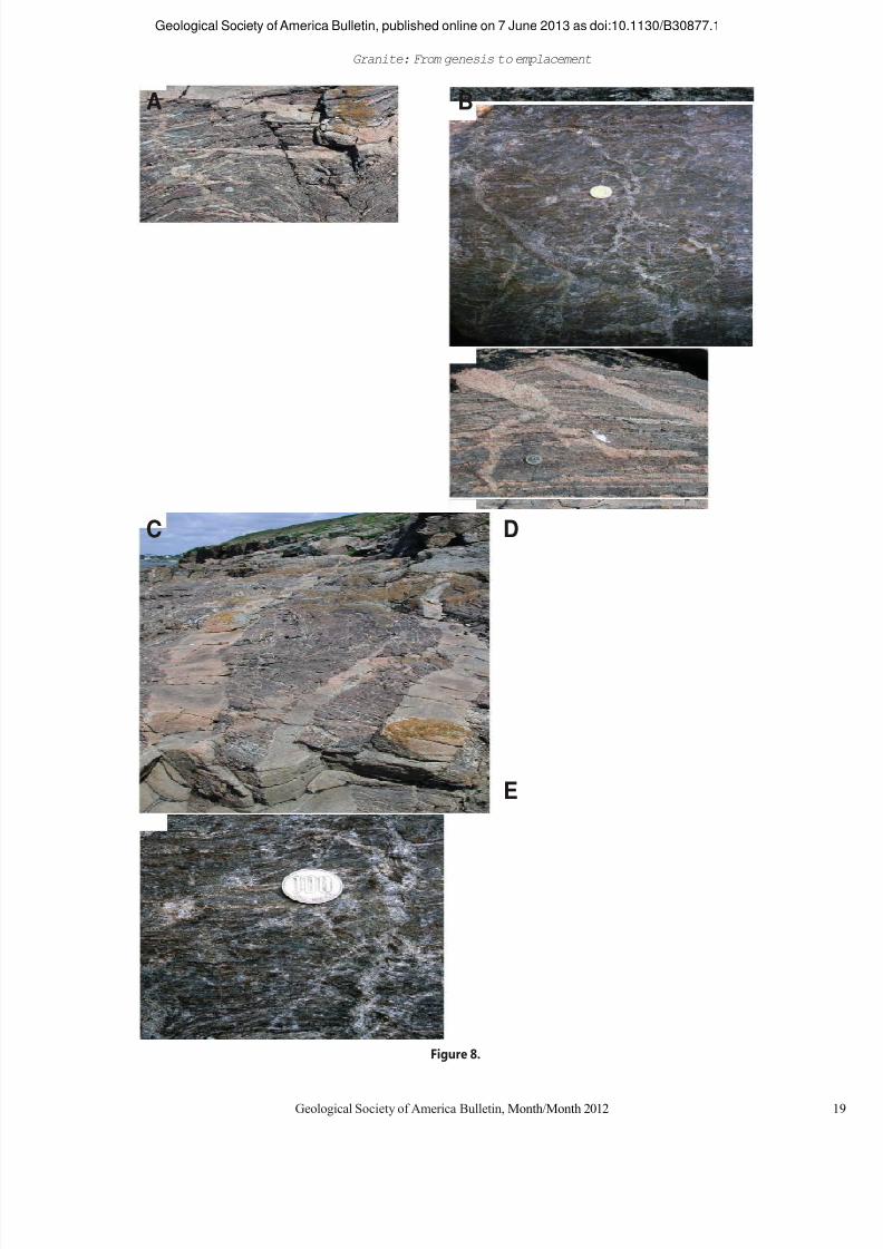
7/27/2019 Brown 2013 Granites Review
http://slidepdf.com/reader/full/brown-2013-granites-review 20/37
Geological Society of America Bulletin, published online on 7 June 2013 as doi:10.1130/B30877.1 Granite: From genesis to emplacement
A B
C D
E
Figure 8.
Geological Society of America Bulletin, Month/Month 2012 19
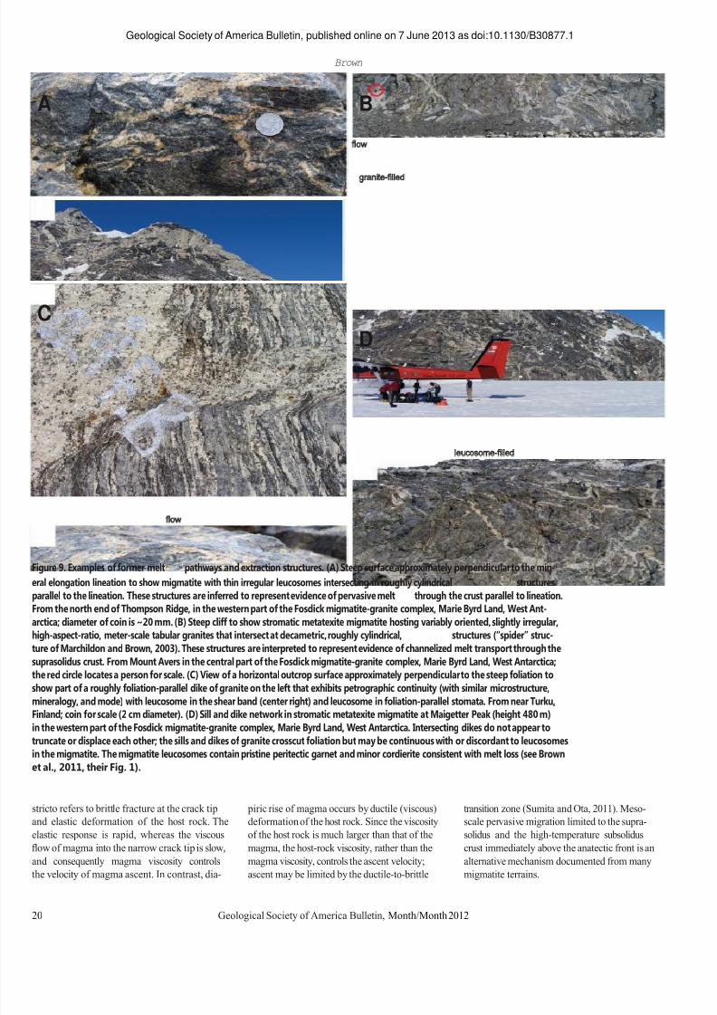
7/27/2019 Brown 2013 Granites Review
http://slidepdf.com/reader/full/brown-2013-granites-review 21/37
Geological Society of America Bulletin, published online on 7 June 2013 as doi:10.1130/B30877.1 Brown
A B
C D
Figure 9. Examples of former melt flow pathways and extraction structures. (A) Steep surface approximately perpendicular to the min- eral elongation lineation to show migmatite with thin irregular leucosomes intersecting in roughly cylindrical leucosome-filled structures parallel to the lineation. These structures are inferred to represent evidence of pervasive melt flow through the crust parallel to lineation. From the north end of Thompson Ridge, in the western part of the Fosdick migmatite-granite complex, Marie Byrd Land, West Ant- arctica; diameter of coin is ~20 mm. (B) Steep cliff to show stromatic metatexite migmatite hosting variably oriented, slightly irregular, high-aspect-ratio, meter-scale tabular granites that intersect at decametric, roughly cylindrical, granite-filled structures (―spider‖ struc- ture of Marchildon and Brown, 2003). These structures are interpreted to represent evidence of channelized melt transport through the suprasolidus crust. From Mount Avers in the central part of the Fosdick migmatite-granite complex, Marie Byrd Land, West Antarctica; the red circle locates a person for scale. (C) View of a horizontal outcrop surface approximately perpendicular to the steep foliation to show part of a roughly foliation-parallel dike of granite on the left that exhibits petrographic continuity (with similar microstructure, mineralogy, and mode) with leucosome in the shear band (center right) and leucosome in foliation-parallel stomata. From near Turku, Finland; coin for scale (2 cm diameter). (D) Sill and dike network in stromatic metatexite migmatite at Maigetter Peak (height 480 m) in the western part of the Fosdick migmatite-granite complex, Marie Byrd Land, West Antarctica. Intersecting dikes do not appear to truncate or displace each other; the sills and dikes of granite crosscut foliation but may be continuous with or discordant to leucosomes in the migmatite. The migmatite leucosomes contain pristine peritectic garnet and minor cordierite consistent with melt loss (see Brown et al., 2011, their Fig. 1). stricto refers to brittle fracture at the crack tip and elastic deformation of the host rock. The elastic response is rapid, whereas the viscous flow of magma into the narrow crack tip is slow, and consequently magma viscosity controls the velocity of magma ascent. In contrast, dia-
piric rise of magma occurs by ductile (viscous) deformation of the host rock. Since the viscosity of the host rock is much larger than that of the magma, the host-rock viscosity, rather than the magma viscosity, controls the ascent velocity; ascent may be limited by the ductile-to-brittle
transition zone (Sumita and Ota, 2011). Meso- scale pervasive migration limited to the supra- solidus and the high-temperature subsolidus crust immediately above the anatectic front is an alternative mechanism documented from many migmatite terrains.
20 Geological Society of America Bulletin, Month/Month 2012
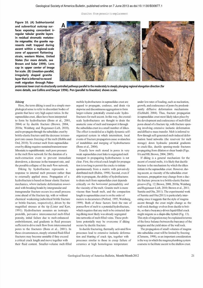
7/27/2019 Brown 2013 Granites Review
http://slidepdf.com/reader/full/brown-2013-granites-review 22/37
Geological Society of America Bulletin, published online on 7 June 2013 as doi:10.1130/B30877.1 Granite: From genesis to emplacement
Figure 10. (A) Subhorizontal and subvertical outcrop sur- A B faces exposing concordant ir- regular tabular granite layers in residual stromatic metatex- ite migmatite; the granite rep- resents melt trapped during ascent
within
a
regional-scale
zone of apparent flattening strain, western Maine, United States (for more details, see Brown and Solar 1999). Lens cap in upper center of image for scale. (B) Lineation-parallel, irregularly shaped granite layer that is inferred to record melt migration through Paleo- proterozoic lower crust via structurally controlled pathways parallel to the moderately to steeply plunging regional elongation direction (for more details, see Collins and Sawyer 1996). Pen (parallel to lineation) shows scale. Diking Here, the term diking is used in a simple mor-
phological sense to refer to discordant bodies of granite that have very high aspect ratios. In the suprasolidus crust, dikes have been interpreted to form by hydrofracture (Bons et al., 2001, 2004) or by ductile fracture (Brown, 2004, 2010a; Weinberg and Regenauer-Lieb, 2010), and to propagate through the subsolidus crust by brittle-elastic fracture until the decrease in trans- port rate causes freezing of the melt (Hobbs and Ord, 2010). To extract melt from suprasolidus crust by diking requires sustained transient near- lithostatic
to
supralithostatic
melt
pore
pressure
in the melt flow network for the duration of a melt-extraction event to prevent immediate drawdown, a decrease in the transport rate, and the possible collapse of the melt flow network. Diking by hydrofracture represents a
response to internal melt pressure rather than to externally applied stress. Propagation of a hydrofracture is based on linear elastic fracture mechanics, where inelastic deformation associ- ated with breaking bonds by intergranular and transgranular fracture occurs in a small process zone ahead of the fracture tip, with or without chemical weakening (subcritical brittle fracture or brittle fracture, respectively), driven by the magnified stresses at the tip (Lister and Kerr, 1991). Hydrofracture assumes an isotropic protolith, pervasive interconnected melt-filled porosity, initial failure due to melt-enhanced embrittlement, and gradients in fluid pressure sufficient to drive melt flow from interconnected pores to the fractures (Bons et al., 2001). In these circumstances, steeply oriented fluid-filled fractures may become unstable if they exceed a critical crack length and move together with their fluid content. Smaller-volume melt-filled
mobile hydrofractures in suprasolidus crust are argued to propagate, coalesce, and drain via stepwise and discontinuous aggregation to form larger-volume potentially crustal-scale hydro- fractures for melt ascent. In this way, the crustal- scale hydrofractures are thought to drain the anatectic zone of melt and transport it through the subsolidus crust in a small number of dikes. The effect is modeled as a highly dynamic self- organized system in which intermittent, local events of fracture propagation cause avalanches of instabilities and merging of hydrofractures (Bons et al., 2004). Exactly
how
melt
stored
in
pores
in
very
weak suprasolidus crust links to segregated melt transport in propagating hydrofractures is not clear. First, the critical crack length for propaga- tion is too long to permit the cracks to initiate spontaneously from a matrix with pervasively distributed melt (Rubin, 1998). Second, even if able to propagate, the ability of hydrofractures to drain melt from suprasolidus crust depends critically on the horizontal permeability and the viscosity of the melt. Granite melt is more viscous than basalt melt, and the compaction length in suprasolidus crust is on the order of meters to decameters (Petford, 1995; Weinberg, 1999). Both of these factors limit the rate of porous flow of melt to a potential hydrofracture, which requires that any melt to be extracted dur- ing diking most likely was already segregated into networks of melt-filled veins. These prob- lems potentially may be overcome if diking occurs by ductile fracture. In ductile fracturing, thermally activated flow
processes lead to extensive inelastic deforma- tion and blunting of crack tips, together with processes similar to those in creep failure of ceramics at high homologous temperature
under low rates of loading, such as nucleation, growth, and coalescence of pores by predomi- nantly diffusive deformation mechanisms (Eichhubl, 2004). Thus, fracture propagation in suprasolidus crust most likely takes place by the development and coalescence of melt-filled pores ahead of a fracture tip, with fracture open- ing involving extensive inelastic deformation and diffusive mass transfer. Melt is inferred to flow through self-generated melt-induced defor- mation band networks (the reservoir for melt storage) down hydraulic potential gradients to crack-like, ductile opening-mode fractures propagating
from
dilation
or
shear
bands
(Figs.
8A and 8B; Brown, 2004, 2005). If diking is a general mechanism for the
ascent of crustal melts, it is likely that ductile fracture is the mechanism by which the dikes initiate in the suprasolidus crust. However, dur- ing ascent, as viscosity of the subsolidus crust increases, propagation may change from a duc- tile fracture process to a brittle-elastic fracture process (Fig. 12; Brown, 2008, 2010a; Weinberg and Regenauer-Lieb, 2010; Brown et al., 2011; Sumita and Ota, 2011). The experimental work of Sumita and Ota (2011) is particularly inter- esting since it suggests that the style of magma ascent through the crust might change as the wall-rock rheology evolves from ductile to brit- tle, so that a buoyancy-driven liquid-filled crack might migrate as a diapir-dike hybrid (Fig. 13). This style of migration may be explained in terms of the force balance between the buoyancy of the magma and the yield stress of the wall rock. The propagation of small volumes of magma
into subsolidus crust will be limited by freezing (Clemens, 1998), so an important consideration is the way in which the magma plumbing system coarsens to facilitate ascent to the shallow crust.
Geological Society of America Bulletin, Month/Month 2012 21
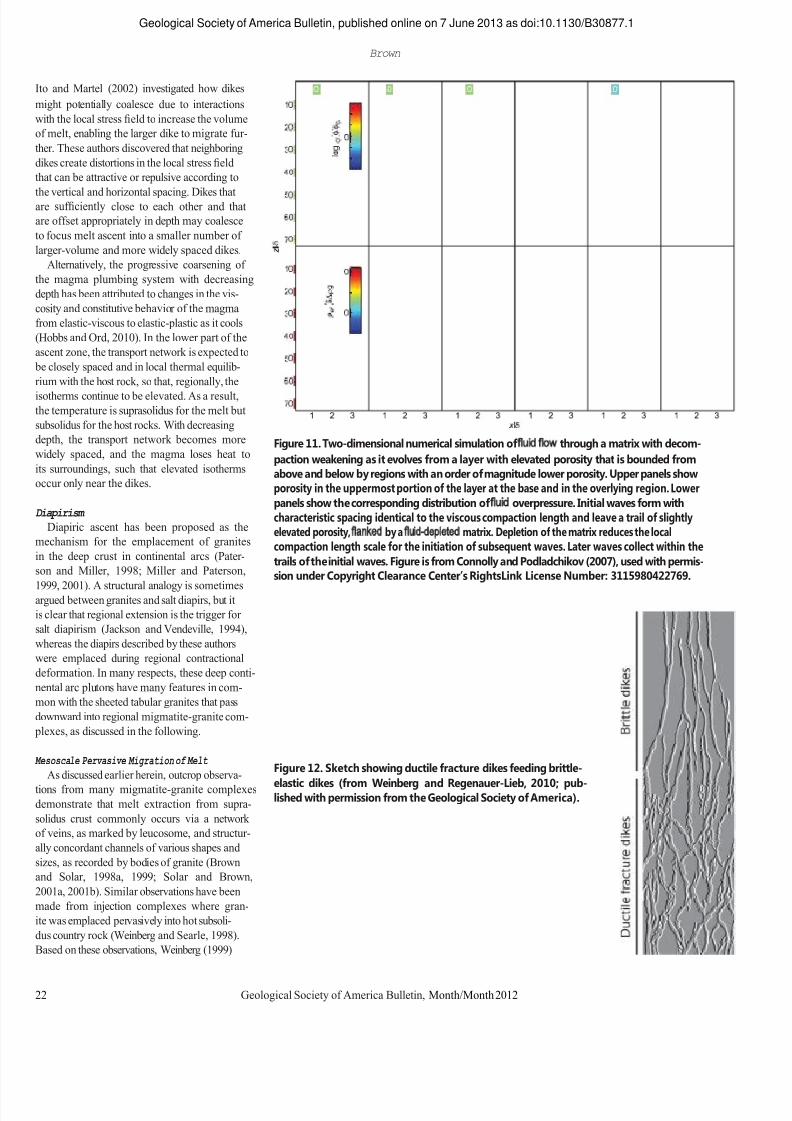
7/27/2019 Brown 2013 Granites Review
http://slidepdf.com/reader/full/brown-2013-granites-review 23/37
Geological Society of America Bulletin, published online on 7 June 2013 as doi:10.1130/B30877.1 Brown
Ito and Martel (2002) investigated how dikes might potentially coalesce due to interactions with the local stress field to increase the volume of melt, enabling the larger dike to migrate fur- ther. These authors discovered that neighboring dikes create distortions in the local stress field that can be attractive or repulsive according to the
vertical
and
horizontal
spacing.
Dikes
that
are sufficiently close to each other and that are offset appropriately in depth may coalesce to focus melt ascent into a smaller number of larger-volume and more widely spaced dikes. Alternatively, the progressive coarsening of
the magma plumbing system with decreasing depth has been attributed to changes in the vis- cosity and constitutive behavior of the magma from elastic-viscous to elastic-plastic as it cools (Hobbs and Ord, 2010). In the lower part of the ascent zone, the transport network is expected to be closely spaced and in local thermal equilib- rium with the host rock, so that, regionally, the isotherms continue to be elevated. As a result, the temperature is suprasolidus for the melt but subsolidus for the host rocks. With decreasing depth, the transport network becomes more widely spaced, and the magma loses heat to its surroundings, such that elevated isotherms occur only near the dikes. Diapirism Diapiric ascent has been proposed as the
mechanism for the emplacement of granites in the deep crust in continental arcs (Pater- son and Miller, 1998; Miller and Paterson, 1999,
2001).
A
structural
analogy
is
sometimes
argued between granites and salt diapirs, but it is clear that regional extension is the trigger for salt diapirism (Jackson and Vendeville, 1994), whereas the diapirs described by these authors were emplaced during regional contractional deformation. In many respects, these deep conti- nental arc plutons have many features in com- mon with the sheeted tabular granites that pass downward into regional migmatite-granite com- plexes, as discussed in the following. Mesoscale Pervasive Migration of Melt As discussed earlier herein, outcrop observa-
tions from many migmatite-granite complexes demonstrate that melt extraction from supra-
Figure 11. Two-dimensional numerical simulation of fluid flow through a matrix with decom- paction weakening as it evolves from a layer with elevated porosity that is bounded from above and below by regions with an order of magnitude lower porosity. Upper panels show porosity in the uppermost portion of the layer at the base and in the overlying region. Lower panels show the corresponding distribution of fluid overpressure. Initial waves form with characteristic spacing identical to the viscous compaction length and leave a trail of slightly elevated porosity, flanked by a fluid-depleted matrix. Depletion of the matrix reduces the local compaction length scale for the initiation of subsequent waves. Later waves collect within the trails of the initial waves. Figure is from Connolly and Podladchikov (2007), used with permis- sion under Copyright Clearance Center’s RightsLink License Number: 3115980422769.
Figure 12. Sketch showing ductile fracture dikes feeding brittle- elastic dikes (from Weinberg and Regenauer-Lieb, 2010; pub- lished with permission from the Geological Society of America).
solidus crust commonly occurs via a network of veins, as marked by leucosome, and structur- ally concordant channels of various shapes and sizes, as recorded by bodies of granite (Brown and Solar, 1998a, 1999; Solar and Brown, 2001a, 2001b). Similar observations have been made from injection complexes where gran- ite was emplaced pervasively into hot subsoli- dus country rock (Weinberg and Searle, 1998). Based on these observations, Weinberg (1999) 22 Geological Society of America Bulletin, Month/Month 2012
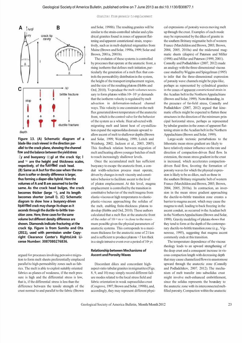
7/27/2019 Brown 2013 Granites Review
http://slidepdf.com/reader/full/brown-2013-granites-review 24/37
Geological Society of America Bulletin, published online on 7 June 2013 as doi:10.1130/B30877.1 Granite: From genesis to emplacement
A B
C
Figure 13. (A) Schematic diagram of a blade-like crack viewed in the direction par- allel to the crack plane, showing the channel flow and the balance between the yield stress y and buoyancy gl at the crack tip; l and are the height and thickness scales, respectively, of the fluid-filled crack head. (B) Same as A but for the case when the me- dium is softer or density difference is larger, thus
forming
a
diaper-dike
hybrid.
Here
the
volumes of A and B are assumed to be the same. As the crack head bulges, the crack becomes thicker (large ), and its length becomes shorter (small l). (C) Schematic diagram to show how a buoyancy-driven liquid-filled crack may change its shape as it ascends through the ductile-to-brittle tran- sition zone. Here, three cases for the same volume but different density difference are shown. Diamonds indicate fracturing at the crack tip. Figure is from Sumita and Ota (2011), used with permission under Copy- right Clearance Center’s RightsLink Li- cense Number: 3087080276836. argued for processes involving pervasive migra- tion to form melt sheets preferentially emplaced parallel to high-permeability zones such as fab- rics. The melt is able to exploit suitably oriented fabrics as planes of weakness, if the melt pres- sure is high and the differential stress is low, that is, if the differential stress is less than the difference between the tensile strength of the crust normal to and parallel to the fabric (Brown
and Solar, 1998b). The resulting granites will be similar to the strain-controlled tabular and cylin- drical granites found in zones of apparent flat- tening and apparent constrictional strain, respec- tively, such as in melt-depleted migmatites from Maine (Brown and Solar, 1998a, 1999; Solar and Brown, 2001a, 2001b). The
evolution
of
these
systems
is
controlled
by processes that operate at the anatectic front, a rising isotherm that defines melt initiation, par- ticularly the generation of a melt flux that con- trols the permeability distribution in the system, the height of the transport/emplacement region, and the size of the resulting plutons (Hobbs and Ord, 2010). To produce the melt volumes neces- sary to form plutons within 104 – 107 yr demands that the isotherm velocity is regulated by melt advection in deformation-induced channel ways. This velocity is one constraint on the melt flux generated down temperature of the anatectic front, which is the control valve for the behavior of the system as a whole. Heat advected with migrating melt and latent heat of crystalliza- tion expand the suprasolidus domain upward to allow ascent of melt to shallower depths (Brown and Solar, 1999; Weinberg, 1999; Leitch and Weinberg, 2002; Jackson et al., 2003, 2005). This feedback relation between migration of melt and heating allows younger batches of melt to reach increasingly shallower levels. Once the accumulated melt has sufficient
buoyancy to escape the anatectic front, a con- duit width-selection process must operate, driven by changes in melt viscosity and consti- tutive
behavior
to
facilitate
ascent
to
the
level
of pluton emplacement. At this level, magma emplacement is controlled by the transition in constitutive behavior of the melt/magma from elastic-viscous at high temperatures to elastic- plastic-viscous approaching the solidus of the melt, enabling finite-thickness plutons to develop (Hobbs and Ord, 2010). These authors calculated that a melt flux at the anatectic front of the order of 10 – 10 m s – 1 is close to the maxi- mum possible given the physical parameters of anatectic systems. This corresponds to a maxi- mum thickness for the anatectic zone of 21 km and is sufficient to produce plutons >3 km thick in a single intrusive event over a period of 106 yr. Relationship between Mechanisms of Ascent and Porosity Waves Discordant dikes and concordant high-
aspect-ratio tabular granites in migmatites (Figs. 8, 9, and 10) may simply record different fail- ure modes related to the local stress field and fabric orientation in weak suprasolidus crust (Cosgrove, 1997; Brown and Solar, 1998b), and, accordingly, they may represent different physi-
cal expressions of porosity waves moving melt up through the crust. Examples of each mode may be represented by the dikes of granite in the southern Brittany migmatite belt of western France (Marchildon and Brown, 2003; Brown, 2004, 2005, 2010a) and the midcrustal mag- matic sheets (diapirs) of Paterson and Miller (1998)
and
Miller
and
Paterson
(1999,
2001).
Connolly and Podladchikov (2007, 2012) made an analogy with the three-dimensional viscous case studied by Wiggins and Spiegelman (1995) to infer that the three-dimensional expression of porosity wave channels might be pipe-like, perhaps as represented by cylindrical granites in the zones of apparent constrictional strain in the Acadian belt in the Northern Appalachians (Brown and Solar, 1999). Notwithstanding, in the presence of far-field stress, Connolly and Podladchikov (2007, 2012) argued that kine- matic effects might be expected to flatten these structures in the direction of the minimum prin- cipal horizontal stress, perhaps as represented by tabular granites in the zones of apparent flat- tening strain in the Acadian belt in the Northern Appalachians (Brown and Solar, 1999). Large-scale tectonic perturbations to the
lithostatic mean stress gradient are likely to have relatively minor influence on the rate and direction of compaction-driven fluid flow. In extension, the mean stress gradient in the crust is increased, which accelerates compaction- driven fluid flow, favoring the formation of porosity waves for which the physical expres- sion is likely to be as dikes, such as those in the
southern
Brittany
migmatite
belt
of
western
France (Marchildon and Brown, 2003; Brown, 2004, 2005, 2010a). In contraction, an inver- sion in the mean stress gradient approaching the ductile-to-brittle transition zone creates a barrier to magma ascent, which may cause the magma to stall, leading to back freezing in the ascent conduit, as occurred in the Acadian belt in the Northern Appalachians (Brown and Solar, 1999). Gravity modeling of plutons shows that they tend to form at the depth of the contempo- rary ductile-to-brittle transition zone (e.g., Vig- neresse, 1995), suggesting that magma ascent commonly ends at this transition. The temperature dependence of the viscous
rheology leads to an upward strengthening of the deep crust and a consequent increase in vis- cous compaction length with decreasing depth that may cause channelized flows to anastomose upward through the anatectic zone (Connolly and Podladchikov, 2007, 2012). The mecha- nism of melt transfer into subsolidus crust might involve melt-enhanced embrittlement, since the solidus represents the boundary to the anatectic zone with its interconnected melt- filled porosity. Compaction within the anatectic
Geological Society of America Bulletin, Month/Month 2012 23

7/27/2019 Brown 2013 Granites Review
http://slidepdf.com/reader/full/brown-2013-granites-review 25/37
Geological Society of America Bulletin, published online on 7 June 2013 as doi:10.1130/B30877.1 Brown
zone may generate strong variations in pressure near the solidus, which may enable deforma- Figure 14. (A) Compilation of
intrusion thickness (T ), width Log A (km2) – 6 – 4 – 2 0 2 4 6
tion at the solidus to be essentially brittle-elastic in character. Under this condition, melt may be transported across the solidus into the sub- solidus (zero-porosity) crust by an elastic shock (Chauveau and Kaminski, 2008). However, the anatectic
front
is
also
an
unstable
interface,
so
that amplification of flow instabilities across the solidus by ductile processes might be an alterna- tive mechanism to continue melt ascent in some circumstances (Connolly and Podladchikov,
(L ), and horizontal area ( A ) data (McCaffrey and Cruden, 2002). The solid S-curve is drawn though the data by eye, and the shaded area represents the
approximate
limits
of
the
data about the curve. Repre- sentative intrusion styles are shown adjacent to appropriate parts of the curve. (B) An in-
1 0
– 1
– 2 – 3
A Laccoliths
Inflated Sills Elastic cracks
Composite Batholiths Plutons
Floor Depression >> Roof Lifting
Roof Lifting >> Floor Depression
‗Lift Off‘ 1998). Experiments by Whitehead and Helfrich terpretation of the S-curve in (1991) showed that flow instabilities develop increasing resistance as they advance into cooler regions across an interface, and the number of advancing fingers rapidly decreases with time to
terms of minimum and maxi- mum growth limit, dominant emplacement mechanism, and depth of emplacement in the
1 0 B
Middle Crust Floor Depression Limit
or De pr. one as the flow becomes focused. In both cases, crust (Cruden and McCaffrey, the physical expression of the transfer of melt across the anatectic front might the tabular and 2002). Arrows show vertical
growth trajectories along a – 1 Shallow Crust
cylindrical granites described earlier that link down into the anatectic zone. A General Model for Granite Emplacement In this section, a general model for the
possible end-member growth curve with a slope a = . This diagram is reproduced with permission of the Geological Society Publishing House (from Brown, 2007).
– 2 – 3 Ro of Li
Elastic Crack (Sill) Limit – 3 – 2 – 1 0 1 2 3
Log L (km) emplacement of laccoliths and plutons is pro- posed. This model accommodates the systematic variation in three-dimensional shape of intru- sions with depth, from shallower laccoliths and wedge-shaped (lopoliths) plutons in the brittle regime to deeper vertical tabular and blobby plutons (e.g., Brown and Solar, 1998b; Brown, 2007, 2010b; Cruden, 1998, 2006). Brittle Regime In the brittle regime, emplacement occurs
when mainly vertical flow switches to predomi- nantly horizontal flow and vertical inflation. Depression of the floor and/or lifting of the roof allow inflation (Cruden, 1998, 2006), sometimes with a component of ductile strain in the aure- ole (e.g., Wagner et al., 2006) or associated with faulting (Benn et al., 1997; Clemens and Benn, 2010). Structural and geophysical data indicate two main types of pluton morphology. Lac- coliths are thin (3 – 4 km) and tend to be equi- dimensional (e.g., Clemens and Benn, 2010); they may have multiple root zones (Vigneresse et al., 1999). These contrast with thick (>10 km) wedge-shaped plutons, which tend to be elon- gated along one direction and tend to have single or only a few root zones (e.g., Brown and Solar, 1998b; Vigneresse et al., 1999). The South Mountain batholith in Nova Scotia, Canada, is large, covering more than 7000 km2, and it has been interpreted as a laccolith based on its inter- nal sheeted structure (Benn et al., 1997). How- ever, the South Mountain batholith is large for a laccolith, and gravity modeling (Benn et al.,
1999) suggests that the constituent plutons have flat or gently dipping floors at ~7.0 km depth underlain by deeper (>10 km) elongate root zones. Thus, it might be better classified with the large wedge-shaped plutons. Dimensional data for sills, laccoliths, plutons,
and composite
batholiths
have
been
compiled
from various sources by McCaffrey and Pet- ford (1997) and McCaffrey and Cruden (2002). Thickness (T ) versus width (L) and horizontal area (A ) data define an S-shaped distribution when plotted in log T versus log A or L space (Fig. 14), which implies vertical limits for intru- sions of T <1 m when L < 10 m and T >10 km when L > 500 km (Fig. 14B). Between the lim- its, T increases with increasing L and A , with a maximum slope of a ~1.5 at L ~1 km, and L/T decreases because vertical thickening domi- nates over horizontal lengthening (McCaffrey and Cruden, 2002). However, as T approaches 10 km, horizontal lengthening begins to domi- nate over vertical thickening and vertical thick- ening appears to be limited to ~15 km. Earlier empirical power-law scaling relationships for laccoliths showing a = 0.8 and plutons showing a = 0.6 (McCaffrey and Petford, 1997; Cruden and McCaffrey, 2001) likely define tangents to the S-curve in Figure 14, rather than represent- ing unique scaling relationships for different classes of intrusions. Limiting factors on vertical growth of plutons
include the host-rock mechanical properties and
the depth of emplacement. To lift the roof, P melt must overcome the lithostatic load and any tec- tonic overpressure. At shallow levels, intrusions that grow by vertical inflation from a larger horizontal area are better able to lift the roof, but with increasing depth, vertical growth of plutons occurs
dominantly
by
floor
depression,
which
is
limited by the thickness of the source and the degree of melting in that zone (Cruden, 1998, 2006; Cruden and McCaffrey, 2001, 2002). Mechanical theories for the initiation and
growth of sills and laccoliths are reasonably well established (e.g., Cruden and McCaffrey, 2002; Bunger and Cruden, 2011). Sills initiate due to a change in the local stress regime associ- ated with magma ascent whereby the minimum principal stress switches from horizontal to ver- tical, transforming vertical ascent to horizontal emplacement (Vigneresse et al., 1999). One key parameter in the analysis of such intrusions is the geometric ratio of the intrusion width to its emplacement depth, L/h. Given sufficient melt pressure, the sill-to-laccolith transition occurs where L/h > 2 – 3, depending on the geometry of the sill and the rheology of the melt. This reflects shallow emplacement (h = 0.5 – 5 km) for intrusions where L = 1 – 10 km, corresponding to the lower half of the S-curve (Fig. 14), with the change of slope at L = 0.1 – 1 km recording the increasing ability of shallow intrusions to lift their roofs as their horizontal area increases. The steepest slope likely represents a limiting curve
24 Geological Society of America Bulletin, Month/Month 2012

7/27/2019 Brown 2013 Granites Review
http://slidepdf.com/reader/full/brown-2013-granites-review 26/37
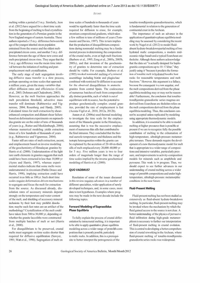
7/27/2019 Brown 2013 Granites Review
http://slidepdf.com/reader/full/brown-2013-granites-review 27/37
Geological Society of America Bulletin, published online on 7 June 2013 as doi:10.1130/B30877.1 Brown
melting within a period of 5 m.y. Similarly, Jeon et al. (2012) have argued for a short time scale from the beginning of melting to final crystalliza- tion in the generation of a Permian granite in the New England orogen of eastern Australia. These authors reported a 15 m.y. difference between the age of the youngest inherited zircon population entrained
from
the
source
and
the
oldest
melt-
precipitated zircon cores, and another 5 m.y. dif- ference between the age of these new cores and melt-precipitated zircon rims. They argue that the 5 m.y. age difference was the mean time inter- val between the initiation of melting and post- emplacement melt crystallization. The early stage of melt segregation involv-
ing diffusive mass transfer is a slow process, perhaps operating on time scales that approach a million years, given the many variables that affect diffusion rates and efficiencies (Costa et al., 2003; Dohmen and Chakraborty, 2003). However, as the melt fraction approaches the melt percolation threshold, advective mass transfer will dominate (Rabinowicz and Vig- neresse, 2004; Rosenberg and Handy, 2005). Calculated times for melt extraction by shear- enhanced compaction and dilatant shear failure based on deformation experiments on suprasoli- dus granite are on the order of tens of thousands of years (e.g., Rutter and Mecklenburgh, 2006), whereas numerical modeling yields extraction times of a few hundreds of thousands of years (e.g., Rabinowicz and Vigneresse, 2004). Faster still are rates of melt extraction, ascent,
and emplacement based on inverse modeling of
the
geochemistry
of
Himalayan
granites
by
Harris et al. (2000). Undersaturation of the light rare earth elements in granites suggests that melt could have been extracted in less than 10,000 yr (Ayres and Harris, 1997), whereas experi- mental studies indicate that some melts were undersaturated in zirconium (Patiño Douce and Harris, 1998), implying extraction could have occurred in as little as 100 yr. Such short time scales require deformation-driven mechanisms to segregate and focus the melt for extraction from the source. As discussed already, dis- solution rates of accessory minerals depend strongly on the temperature and water content of the melt, and shielding of accessory mineral inclusions by their host may prohibit dissolu- tion; maybe such fast rates are an artifact of the methodology? Crystallization of the melt could have taken from 500 to 30,000 yr, depending on whether the granite laccoliths were constructed from multiple batches of melt or not (Harris et al., 2000). For disequilibrium to be preserved, crustal
melts must segregate on time scales shorter than required for diffusive equilibration (Sawyer, 1991; Watt et al., 1996). Segregation of melt on
time scales of hundreds to thousands of years would be significantly faster than the time scale required for diffusion to erase, for example, strontium compositional gradients, which takes a few million to tens of millions of years (Tom- masini and Davies, 1997). This in turn implies that the production of disequilibrium composi- tions
during
nonmodal
melting
may
be
a funda-
mental process in determining the composition of the crustal melts, even at high melt fractions (Barbero et al., 1995; Zeng et al., 2005a, 2005b, 2005c), and that inversion of the geochemis- try of granites to determine rate of extraction should be viable. For example, Barbero et al. (1995) invoked nonmodal melting of a mineral assemblage including biotite and plagioclase combined with restricted Sr diffusion to account for the observed disequilibrium in anatectic granites from central Spain. The coalescence of numerous batches of melt from composition- ally distinct protoliths, each of which is out of equilibrium with its source, has the potential to produce geochemically complex crustal gran- ites, provided the rate of emplacement is fast (Acosta-Vigil et al., 2010, 2012a, 2012b). Annen et al. (2006a) used thermal modeling
to investigate the time scale for the emplace- ment of the Manaslu granite in the Himalayas, assuming that is was the successive emplace- ment of numerous thin sills that contributed to the final intrusion. They concluded that the ther- mal aureole temperature and thickness and the isotopic heterogeneities within the granite can be explained by the accretion of 20 – 60-m-thick sills
of
melt
emplaced
every
20,000 – 60,000
yr
for 5 m.y. Five million years is two to four orders of magnitude longer than the range of time scales implied by the inverse geochemical modeling of Harris et al. (2000). QUO VADIMUS? Resolution of some of the issues discussed
in this review requires advances in a number of different specialties, wider application of newly developed techniques, and, in some cases, more data to test hypotheses. Examples where prog- ress may be made in the next decade include the following topics. Forward Modeling of Suprasolidus Phase Equilibria To fully explain the process of crustal differ-
entiation by intracrustal melting, it is important to be able to apply quantitative phase equilibria modeling across a wider range of protolith com- positions than is presently possible, particularly to mafic rocks. In addition, this is a prerequi- site to better interpret the petrogenesis of the
tonalite-trondhjemite-granodiorite series, which is fundamental in relation to the generation of continental crust in the Archean. The importance of such an advance in the
application of quantitative phase equilibria mod- eling may be assessed by considering the recent work by Nagel et al. (2012) to model fluid- absent
hydrate-breakdown
partial
melting
of
two
hydrated mafic compositions, a modern mid- oceanic-ridge basalt and a typical Eoarchean arc tholeiite. Although these authors acknowledge that the data set ―is actually designed for haplo- granitic compositions up to 10 – 12 kbar,‖ they justify using it ―because it predicts the forma- tion of tonalitic melt in hydrated basaltic host rocks for reasonable temperatures and melt fractions.‖ However, this argument is a fallacy, because the consequent is a non sequitur, and the melt compositions derived from the phase equilibria modeling may or may not be reason- able! Furthermore, the conclusion that tonalite- trondhjemite-granodiorite series magmas are derived from Eoarchean arc tholeiites relies on the melt compositions derived from the phase equilibria modeling. Thus, this conclusion can- not be accepted unless replicated by modeling using appropriate thermodynamic models. In addition, it is essential to be able to model
melting at higher pressures than is possible at present if we are to recognize fully the possible contribution of melting to the exhumation of high-temperature, ultrahigh-pressure metamor- phic terranes. These demands require the devel- opment of a new thermodynamic model for melt that
is
appropriate
to
a wider
range
of
composi-
tions and intensive variables, particularly pres- sure, and improvements to activity-composition models for minerals such as amphibole and pyroxene. This work is in progress. Thus, we should expect to see further advances in our understanding of crustal melting across a wider range of protolith compositions and under high- temperature, ultrahigh-pressure metamorphic conditions in the near future. Fluid-Present Melting Fluid-present melting has not been studied as
extensively as fluid-absent hydrate-breakdown melting. In particular, fluid-present melting may be invoked where the mechanism by which the fluid gained access to the source is not clear. A better understanding of the physics of pervasive fluid infiltration during high-grade metamor- phism is necessary to further our interpretation of fluid-present melting in crustal evolution. This is central to developing a better comprehen- sion of crustal reworking in the Archean, where fluid-present melting of tonalite-trondhjemite- granodiorite series rocks was widespread.
26 Geological Society of America Bulletin, Month/Month 2012
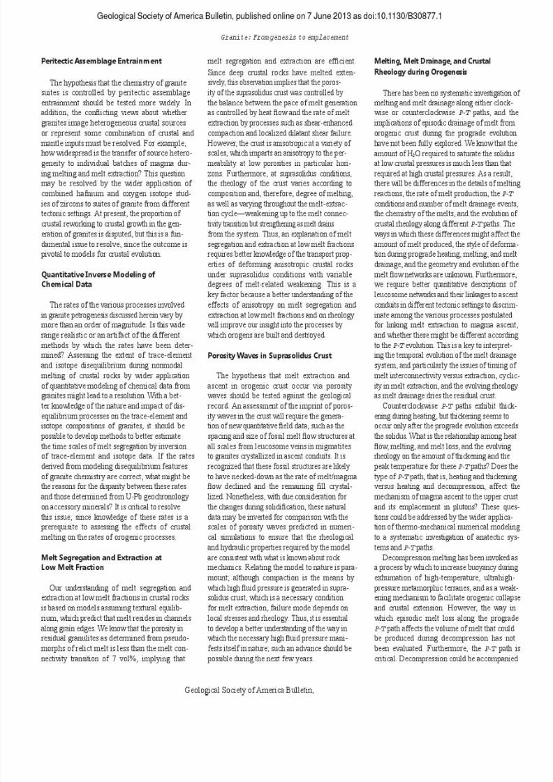
7/27/2019 Brown 2013 Granites Review
http://slidepdf.com/reader/full/brown-2013-granites-review 28/37

7/27/2019 Brown 2013 Granites Review
http://slidepdf.com/reader/full/brown-2013-granites-review 29/37
7/27/2019 Brown 2013 Granites Review
http://slidepdf.com/reader/full/brown-2013-granites-review 30/37
7/27/2019 Brown 2013 Granites Review
http://slidepdf.com/reader/full/brown-2013-granites-review 31/37

7/27/2019 Brown 2013 Granites Review
http://slidepdf.com/reader/full/brown-2013-granites-review 32/37

7/27/2019 Brown 2013 Granites Review
http://slidepdf.com/reader/full/brown-2013-granites-review 33/37
7/27/2019 Brown 2013 Granites Review
http://slidepdf.com/reader/full/brown-2013-granites-review 34/37
7/27/2019 Brown 2013 Granites Review
http://slidepdf.com/reader/full/brown-2013-granites-review 35/37

7/27/2019 Brown 2013 Granites Review
http://slidepdf.com/reader/full/brown-2013-granites-review 36/37

7/27/2019 Brown 2013 Granites Review
http://slidepdf.com/reader/full/brown-2013-granites-review 37/37