Embed Size (px)
Citation preview
STUDENT NAME:
Broward College
ATC Radar Procedures Course ATT2821C
Student Study Guide
ATT2821C i
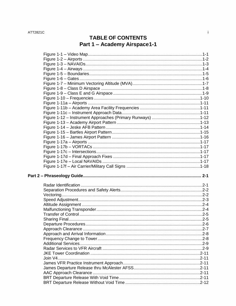
TABLE OF CONTENTS
Part 1 – Academy Airspace 1-1
Figure 1-1 – Video Map ............................................................................................... 1-1 Figure 1-2 – Airports ................................................................................................... 1-2 Figure 1-3 – NAVAIDs ................................................................................................. 1-3 Figure 1-4 – Airways ................................................................................................... 1-4 Figure 1-5 – Boundaries .............................................................................................. 1-5 Figure 1-6 – Gates ...................................................................................................... 1-6 Figure 1-7 – Minimum Vectoring Altitude (MVA) ..........................................................1-7 Figure 1-8 – Class D Airspace ....................................................................................1-8 Figure 1-9 – Class E and G Airspace ..........................................................................1-9 Figure 1-10 – Frequencies ........................................................................................ 1-10 Figure 1-11a – Airports ............................................................................................. 1-11 Figure 1-11b – Academy Area Facility Frequencies .................................................. 1-11 Figure 1-11c – Instrument Approach Data ................................................................. 1-11 Figure 1-12 – Instrument Approaches (Primary Runways) ........................................ 1-12 Figure 1-13 – Academy Airport Pattern ..................................................................... 1-13 Figure 1-14 – Jeske AFB Pattern .............................................................................. 1-14 Figure 1-15 – Bartles Airport Pattern ......................................................................... 1-15 Figure 1-16 – James Airport Pattern ......................................................................... 1-16 Figure 1-17a – Airports ............................................................................................. 1-17 Figure 1-17b – VORTACs ......................................................................................... 1-17 Figure 1-17c – Intersections ...................................................................................... 1-17 Figure 1-17d – Final Approach Fixes ........................................................................ 1-17 Figure 1-17e – Local NAVAIDs ................................................................................. 1-17 Figure 1-17f – Air Carrier/Military Call Signs ............................................................. 1-18
Part 2 – Phraseology Guide .................................................................................................. 2-1
Radar Identification .....................................................................................................2-1 Separation Procedures and Safety Alerts ....................................................................2-2 Vectoring ..................................................................................................................... 2-2 Speed Adjustment ....................................................................................................... 2-3 Altitude Assignment ....................................................................................................2-4 Malfunctioning Transponder ........................................................................................ 2-4 Transfer of Control ...................................................................................................... 2-5 Sharing Final ............................................................................................................... 2-5 Departure Procedures .................................................................................................2-6 Approach Clearance ...................................................................................................2-7 Approach and Arrival Information ................................................................................2-8 Frequency Change to Tower ....................................................................................... 2-8 Additional Services......................................................................................................2-9 Radar Services to VFR Aircraft ...................................................................................2-9 JKE Tower Coordination ........................................................................................... 2-11 Join V4 ......................................................................................................................2-11 James VFR Practice Instrument Approach ................................................................ 2-11 James Departure Release thru McAlester AFSS ....................................................... 2-11 AAC Approach Clearance ......................................................................................... 2-11 BRT Departure Release With Void Time ................................................................... 2-11 BRT Departure Release Without Void Time .............................................................. 2-12
ATT2821C ii
TABLE OF CONTENTS (Continued)
Part 3 – Facility Orders and Directives ................................................................................. 3-1
Letter of Agreement between Aero ARTCC and Academy TRACON ..........................3-1 Letter of Agreement between Jeske Air Force Base ATCT and Academy TRACON...3-7 Letter of Agreement between Springfield ATCT and Academy TRACON ................... 3-9 Academy TRACON Order 7110.24C, Arrival/Departure Procedures and Responsibilities ......................................................................................................... 3-11 Order 7110.22D, Arrival and Departure Handling of High-Performance Aircraft .........3-19 Order 7110.3, Strip Marking……………………………………………………………….3-23
Part 4 – Position Relief Checklist ......................................................................................... 4-1
Position Relief Checklist .............................................................................................. 4-1 Traffic ......................................................................................................................... 4-1
Part 5 – Academy Approach Plates ...................................................................................... 5-1
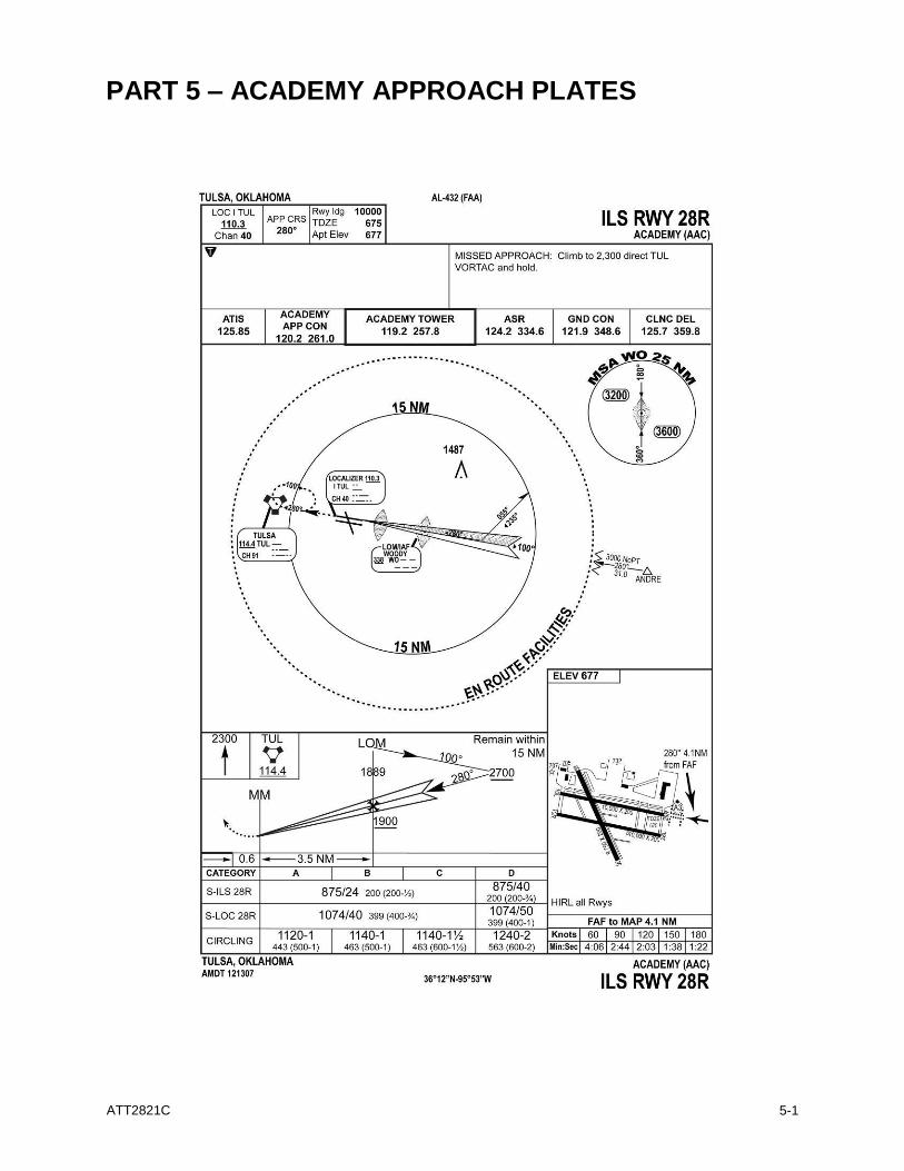
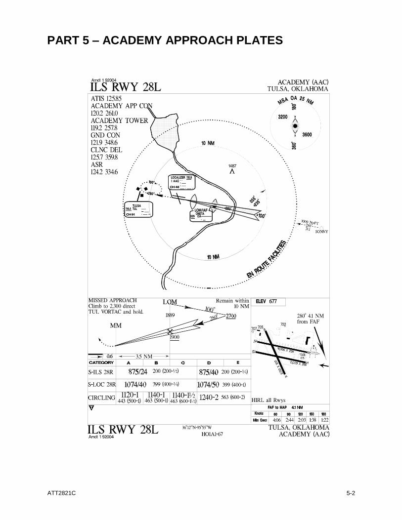
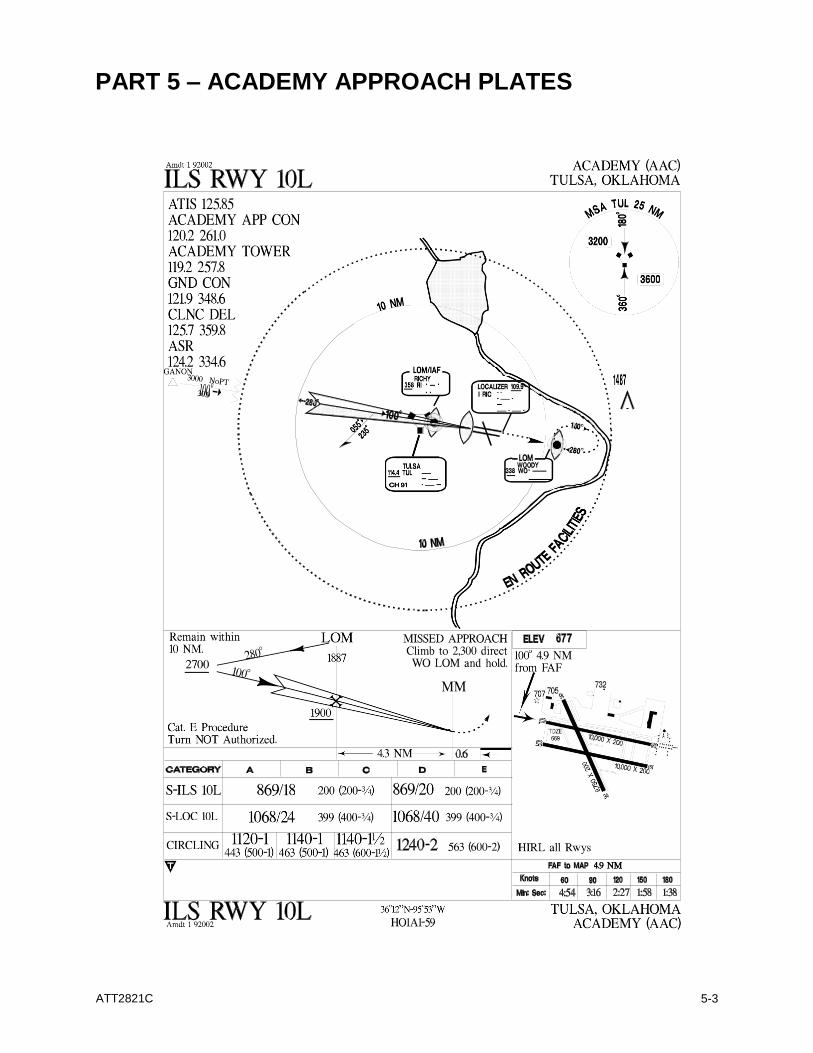
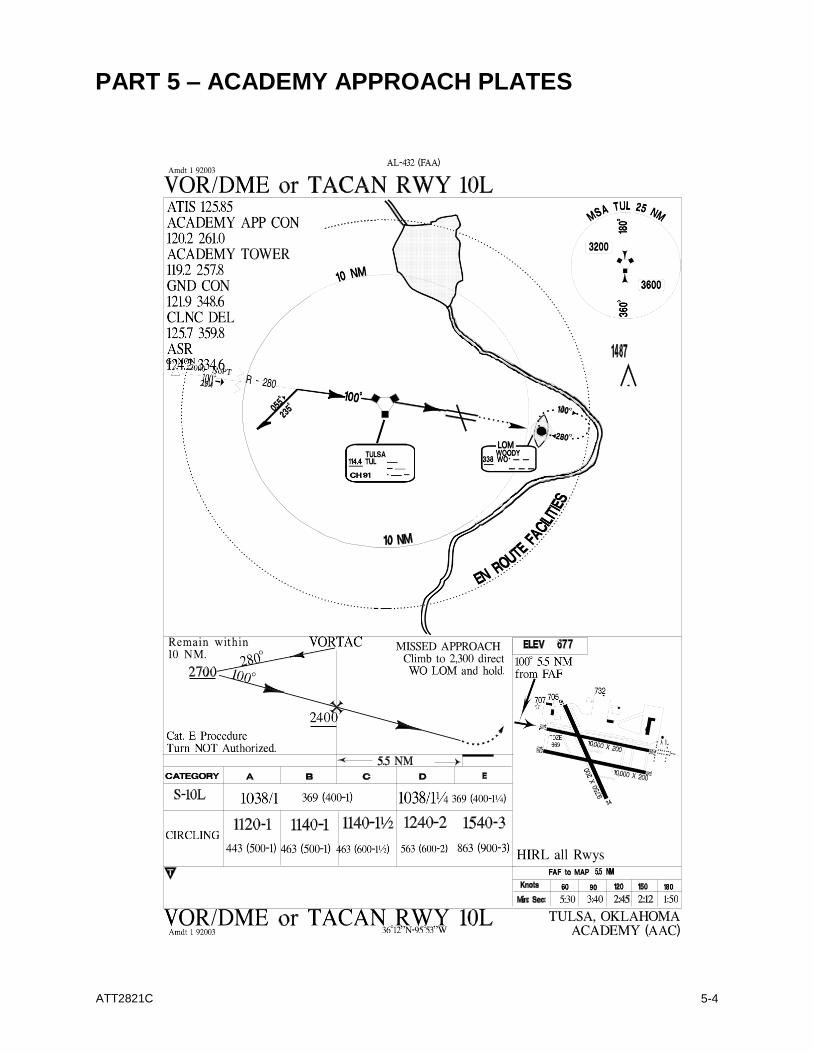
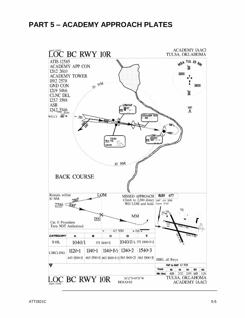
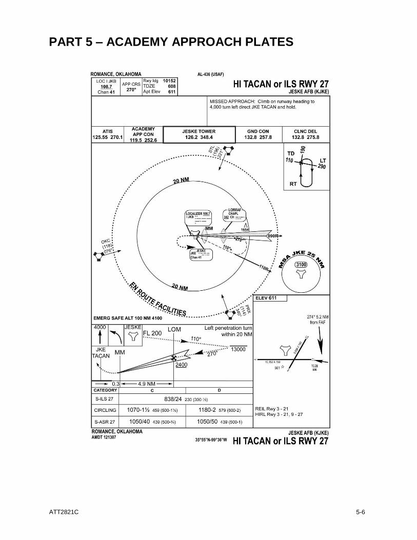
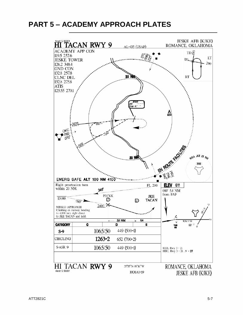
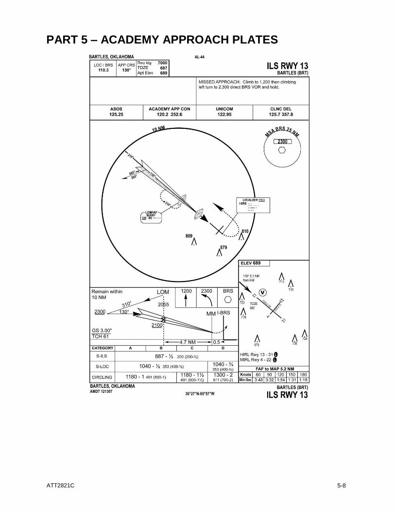
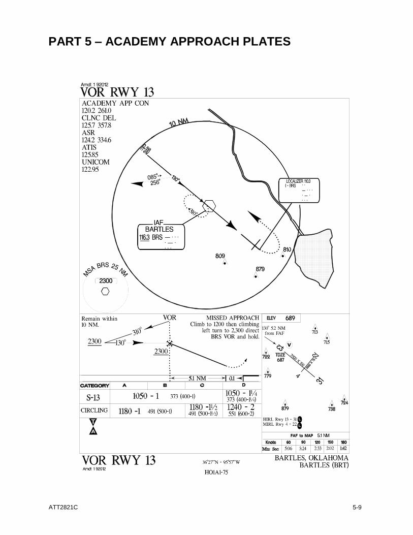
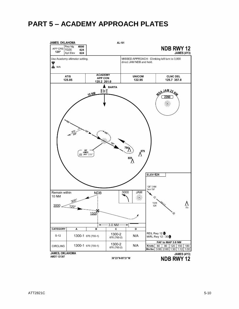
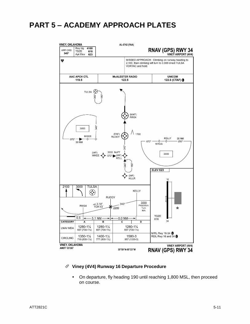
ILS Runway 28R ......................................................................................................... 5-1 ILS Runway 28L ..........................................................................................................5-2 ILS Runway 10L ..........................................................................................................5-3 VOR/DME or TACAN Runway 10L ............................................................................. 5-4 LOC BC Runway 10R ................................................................................................. 5-5 HI TACAN or ILS Runway 27 ...................................................................................... 5-6 HI TACAN Runway 9 .................................................................................................. 5-7 ILS Runway 13 ............................................................................................................5-8 VOR Runway 13 ......................................................................................................... 5-9 NDB Runway 12 ....................................................................................................... 5-10 RNAV (GPS) Runway 34 .......................................................................................... 5-11
Part 6 – Landing Wake Turbulence Minima .......................................................................... 6-1
PART 1 - ACADEMY AIRSPACE
ATT2821C
1-1
BARTS
BRS
COLIN PRYOR
AVANT
BRT JAM
4Y3
TUL
RICHY
WOODY
ONETA
MAYES
SHAWN Z91
JKE 4V4
PECKK
NOBLE
CHAPL
ATOKA KILLR
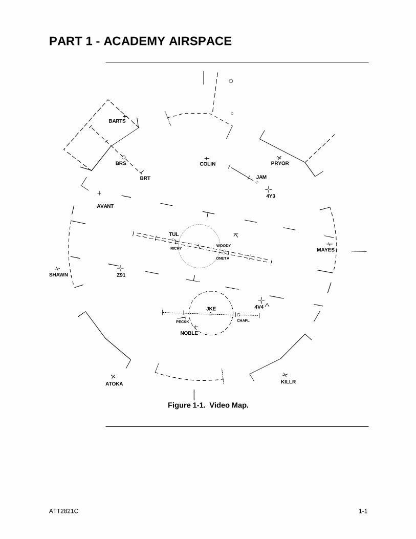
Figure 1-1. Video Map.
ATT2821C
1-2
PART 1 - ACADEMY AIRSPACE (Continued)
BRT
BARTLES
Rwys 13/31
4Y3 JAMES
Rwys 12/30
AAC
Z91 LAZY J
ACADEMY
Rwys 10R/L, 28R/L and 16/34
JKE JESKE
Rwys 09/27
4V4 VINEY
Rwys 16/34
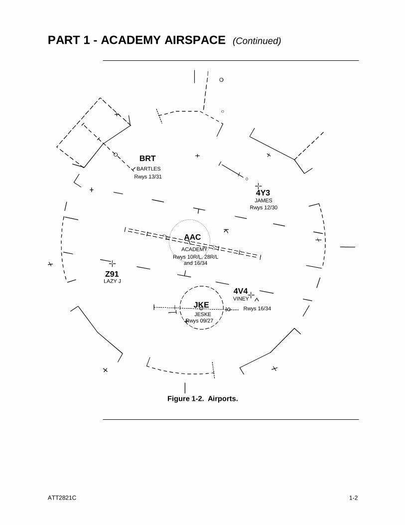
Figure 1-2. Airports.
PART 1 - ACADEMY AIRSPACE (Continued)
ATT2821C
1-3
BRS
(BARTLES)
JAM TVOR (JAMES)
NDB
TUL
(TULSA)
VORTAC
JKE
(JESKE)
TACAN
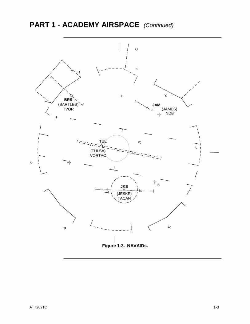
Figure 1-3. NAVAIDs.
ATT2821C
1-4
PART 1 - ACADEMY AIRSPACE (Continued)
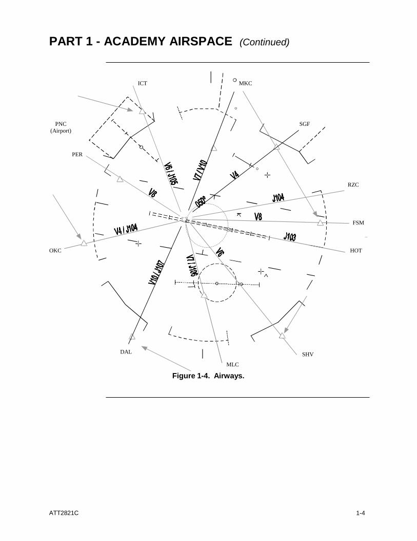
ICT MKC
PNC
(Airport)
SGF
PER
RZC
FSM
OKC HOT
DAL
MLC
Figure 1-4. Airways.
SHV
ATT2821C
1-5
PART 1 - ACADEMY AIRSPACE (Continued)
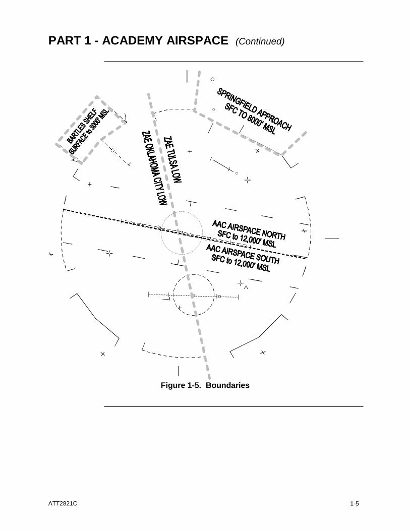
Figure 1-5. Boundaries
ATT2821C
1-6
PART 1 - ACADEMY AIRSPACE (Continued)
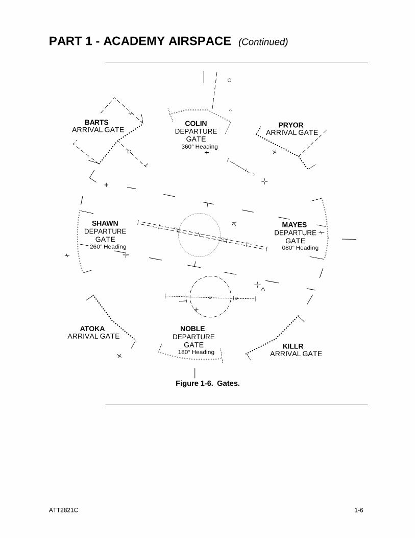
BARTS ARRIVAL GATE
COLIN DEPARTURE
GATE 360° Heading
PRYOR ARRIVAL GATE
SHAWN DEPARTURE
GATE 260° Heading
MAYES DEPARTURE
GATE 080° Heading
ATOKA
ARRIVAL GATE NOBLE
DEPARTURE GATE
180° Heading
KILLR ARRIVAL GATE
Figure 1-6. Gates.
ATT2821C
1-7
PART 1 - ACADEMY AIRSPACE (Continued)
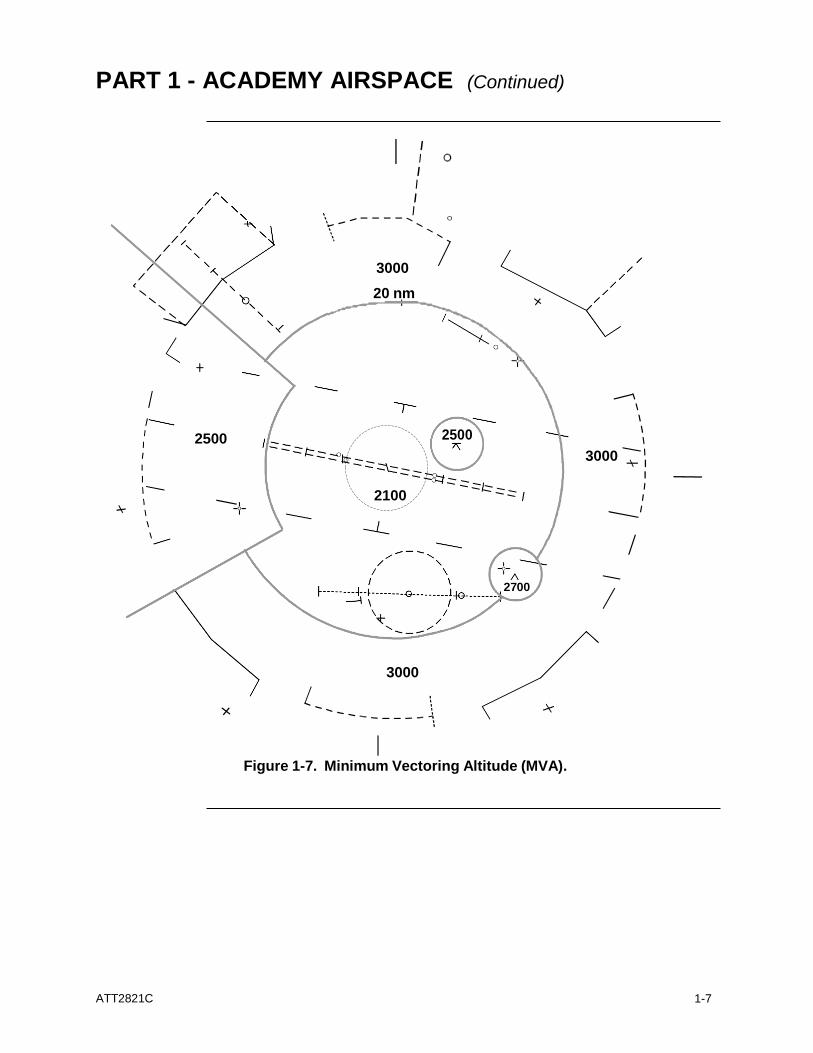
3000
20 nm
2500 2500
3000
2100
2700
3000
Figure 1-7. Minimum Vectoring Altitude (MVA).
ATT2821C
1-8
PART 1 - ACADEMY AIRSPACE (Continued)
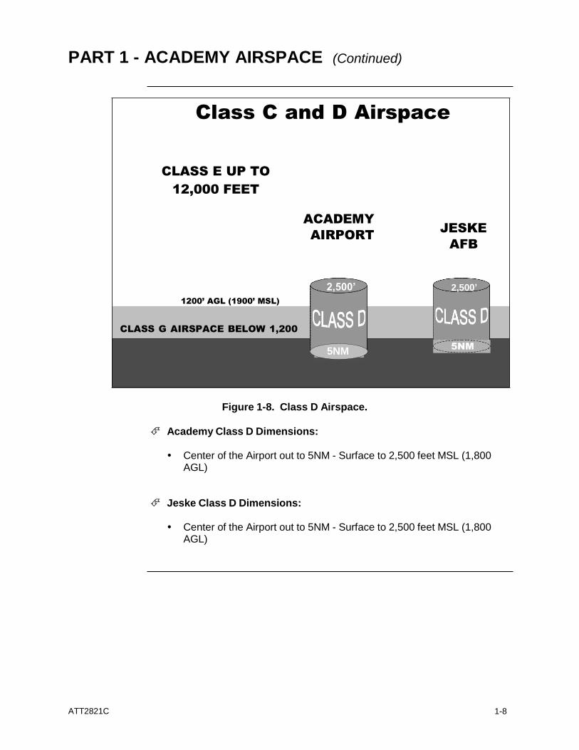
Class C and D Airspace
CLASS E UP TO
12,000 FEET
ACADEMY
AIRPORT
JESKE
AFB
1200’ AGL (1900’ MSL)
4,700’ MSL
2,500’
CLASS G AIRSPACE BELOW 1,200
5NM
Figure 1-8. Class D Airspace.
Academy Class D Dimensions:
Center of the Airport out to 5NM - Surface to 2,500 feet MSL (1,800
AGL)
Jeske Class D Dimensions:
Center of the Airport out to 5NM - Surface to 2,500 feet MSL (1,800 AGL)
2,500’
5NM
ATT2821C
1-9
PART 1 - ACADEMY AIRSPACE (Continued)
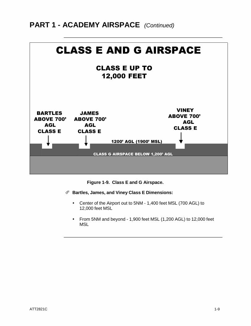
CLASS E AND G AIRSPACE
CLASS E UP TO
12,000 FEET
BARTLES
ABOVE 700’
AGL
CLASS E
JAMES
ABOVE 700’
AGL
CLASS E
VINEY
ABOVE 700’
AGL
CLASS E
1200’ AGL (1900’ MSL)
CLASS G AIRSPACE BELOW 1,200’ AGL
Figure 1-9. Class E and G Airspace.
Bartles, James, and Viney Class E Dimensions:
Center of the Airport out to 5NM - 1,400 feet MSL (700 AGL) to
12,000 feet MSL
From 5NM and beyond - 1,900 feet MSL (1,200 AGL) to 12,000 feet
MSL
ATT2821C
1-10
PART 1 - ACADEMY AIRSPACE (Continued)
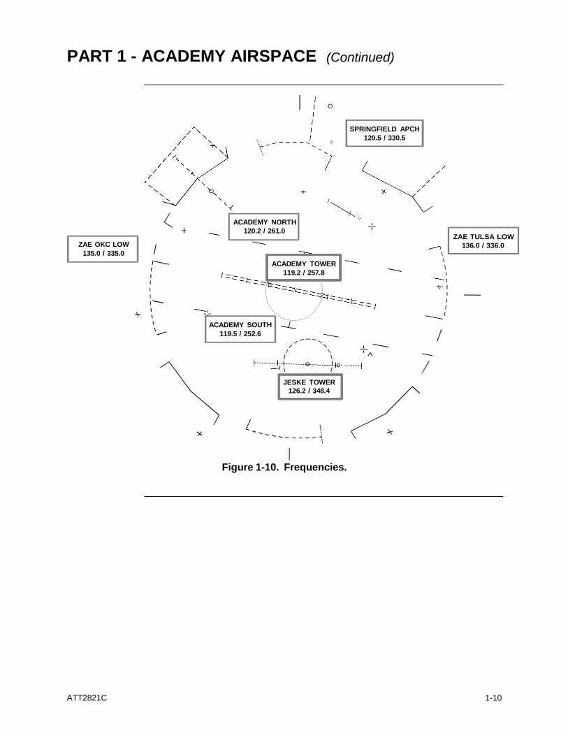
SPRINGFIELD APCH
120.5 / 330.5
ZAE OKC LOW
135.0 / 335.0
ACADEMY NORTH
120.2 / 261.0
ACADEMY TOWER
119.2 / 257.8
ZAE TULSA LOW
136.0 / 336.0
ACADEMY SOUTH
119.5 / 252.6
JESKE TOWER
126.2 / 348.4
Figure 1-10. Frequencies.
ATT2821C
1-11
PART 1 - ACADEMY AIRSPACE (Continued)
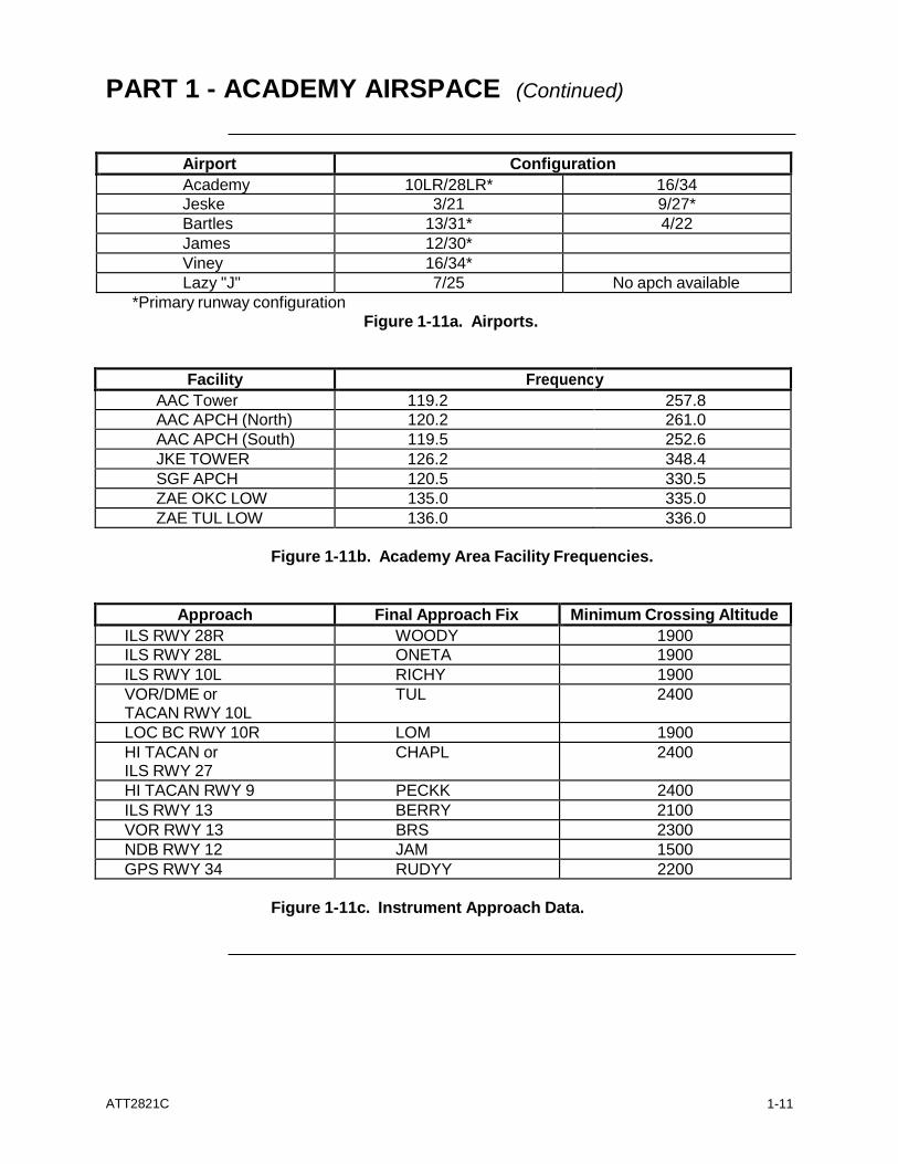
Airport Configuration
Academy 10LR/28LR* 16/34
Jeske 3/21 9/27*
Bartles 13/31* 4/22
James 12/30* Viney 16/34* Lazy "J" 7/25 No apch available
*Primary runway configuration Figure 1-11a. Airports.
Facility Frequenc y
AAC Tower 119.2 257.8
AAC APCH (North) 120.2 261.0
AAC APCH (South) 119.5 252.6
JKE TOWER 126.2 348.4
SGF APCH 120.5 330.5
ZAE OKC LOW 135.0 335.0
ZAE TUL LOW 136.0 336.0
Figure 1-11b. Academy Area Facility Frequencies.
Approach Final Approach Fix Minimum Crossing Altitude
ILS RWY 28R WOODY 1900
ILS RWY 28L ONETA 1900
ILS RWY 10L RICHY 1900
VOR/DME or TACAN RWY 10L
TUL 2400
LOC BC RWY 10R LOM 1900
HI TACAN or ILS RWY 27
CHAPL 2400
HI TACAN RWY 9 PECKK 2400
ILS RWY 13 BERRY 2100
VOR RWY 13 BRS 2300
NDB RWY 12 JAM 1500
GPS RWY 34 RUDYY 2200
Figure 1-11c. Instrument Approach Data.
ATT2821C
1-12
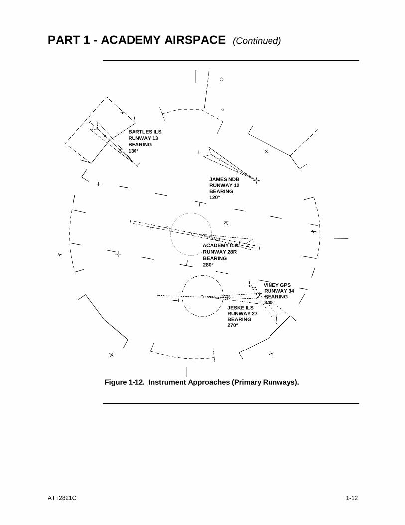
PART 1 - ACADEMY AIRSPACE (Continued)
BARTLES ILS
RUNWAY 13
BEARING
130°
JAMES NDB
RUNWAY 12
BEARING
120°
ACADEMY ILS
RUNWAY 28R
BEARING
280°
JESKE ILS RUNWAY 27 BEARING 270°
VINEY GPS RUNWAY 34 BEARING 340°
Figure 1-12. Instrument Approaches (Primary Runways).
ATT2821C
1-13
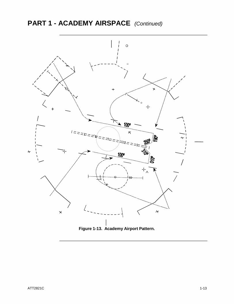
PART 1 - ACADEMY AIRSPACE (Continued)
Figure 1-13. Academy Airport Pattern.
ATT2821C
1-14
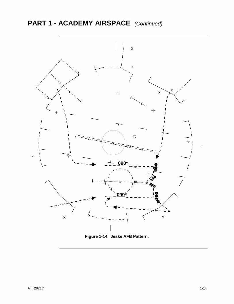
PART 1 - ACADEMY AIRSPACE (Continued)
090o
090o
Figure 1-14. Jeske AFB Pattern.
ATT2821C
1-15
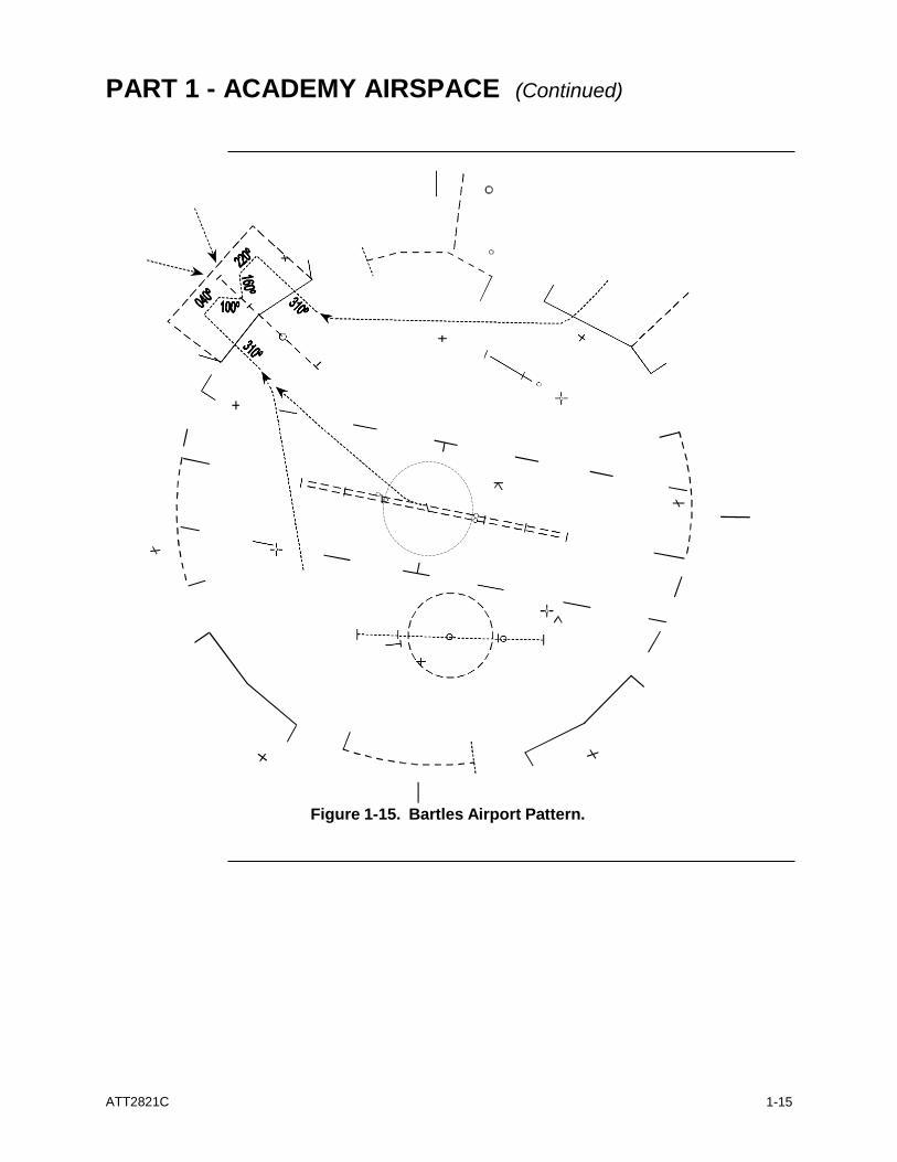
PART 1 - ACADEMY AIRSPACE (Continued)
Figure 1-15. Bartles Airport Pattern.
ATT2821C
1-16
PART 1 - ACADEMY AIRSPACE (Continued)
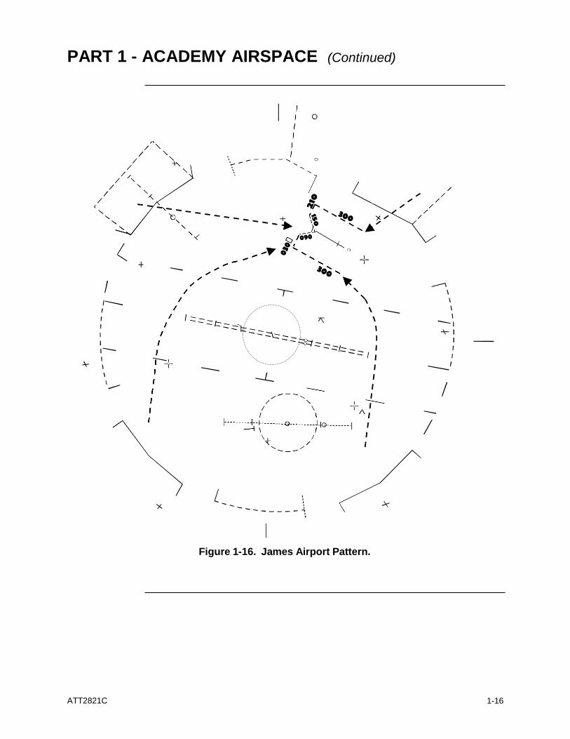
Figure 1-16. James Airport Pattern.
ATT2821C
1-17
PART 1 - ACADEMY AIRSPACE (Continued)
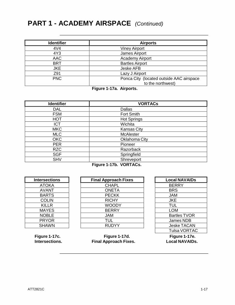
Final Approach Fixes
CHAPL ONETA
PECKK
RICHY
WOODY
BERRY
JAM
TUL
RUDYY
Local NAVAIDs
BERRY BRS
JAM
JKE
TUL
LOM
Bartles TVOR
James NDB
Jeske TACAN
Tulsa VORTAC
Figure 1-17c. Figure 1-17d. Figure 1-17e.
Intersections. Final Approach Fixes. Local NAVAIDs.
Identifier Airports
4V4 Viney Airport 4Y3 James Airport
AAC Academy Airport
BRT Bartles Airport
JKE Jeske AFB
Z91 Lazy J Airport
PNC Ponca City (located outside AAC airspace to the northwest)
Figure 1-17a. Airports.
Identifier VORTACs
DAL Dallas FSM Fort Smith
HOT Hot Springs
ICT Wichita
MKC Kansas City
MLC McAlester
OKC Oklahoma City
PER Pioneer
RZC Razorback
SGF Springfield
SHV Shreveport
Figure 1-17b. VORTACs.
Intersections
ATOKA AVANT
BARTS
COLIN
KILLR
MAYES
NOBLE
PRYOR
SHAWN
ATT2821C
1-18
PART 1 - ACADEMY AIRSPACE (Continued)
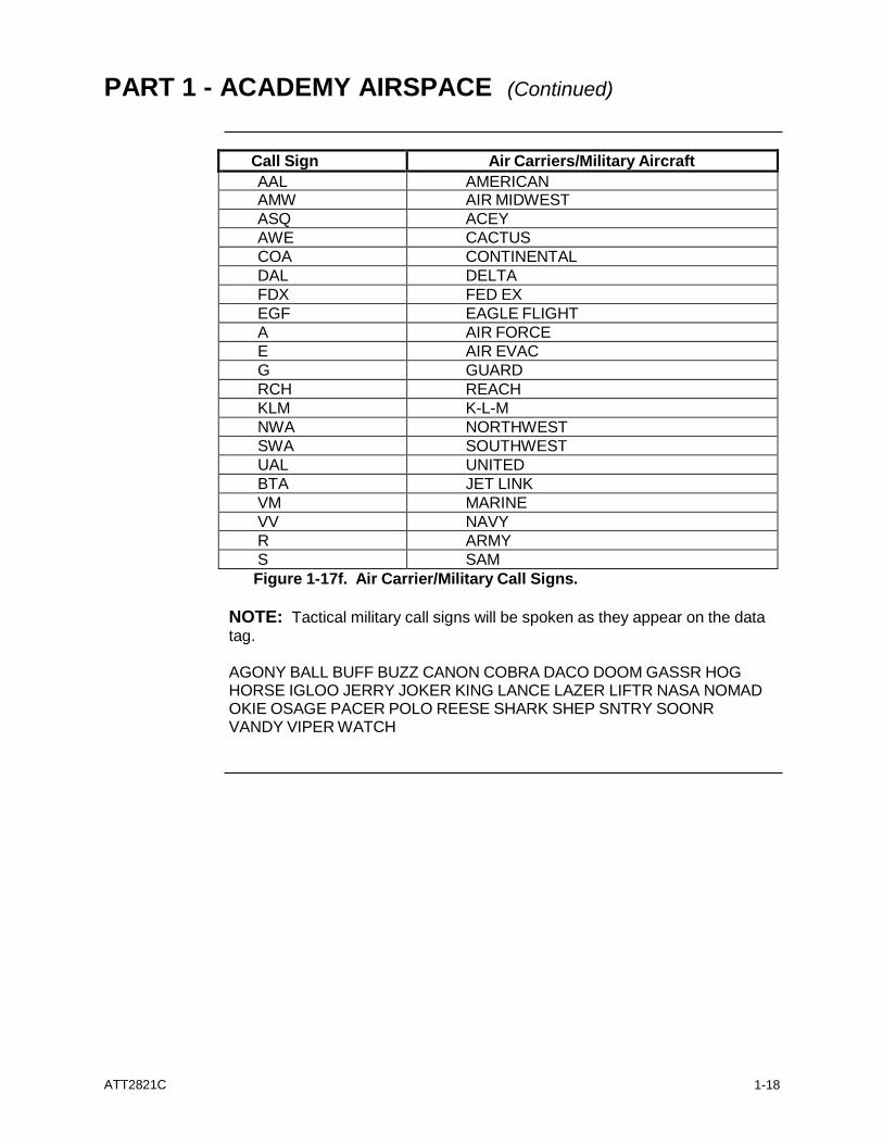
Call Sign Air Carriers/Military Aircraft
AAL AMERICAN AMW AIR MIDWEST
ASQ ACEY
AWE CACTUS
COA CONTINENTAL
DAL DELTA
FDX FED EX
EGF EAGLE FLIGHT
A AIR FORCE
E AIR EVAC
G GUARD
RCH REACH
KLM K-L-M
NWA NORTHWEST
SWA SOUTHWEST
UAL UNITED
BTA JET LINK
VM MARINE
VV NAVY
R ARMY
S SAM
Figure 1-17f. Air Carrier/Military Call Signs.
NOTE: Tactical military call signs will be spoken as they appear on the data tag.
AGONY BALL BUFF BUZZ CANON COBRA DACO DOOM GASSR HOG HORSE IGLOO JERRY JOKER KING LANCE LAZER LIFTR NASA NOMAD OKIE OSAGE PACER POLO REESE SHARK SHEP SNTRY SOONR VANDY VIPER WATCH
PART 2 - PHRASEOLOGY GUIDE
ATT2821C
2-1
Radar
Identification
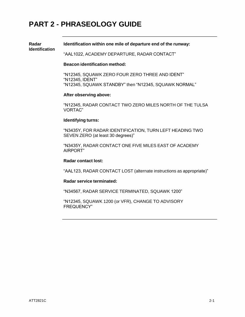
Identification within one mile of departure end of the runway: “AAL1022, ACADEMY DEPARTURE, RADAR CONTACT”
Beacon identification method:
“N12345, SQUAWK ZERO FOUR ZERO THREE AND IDENT” “N12345, IDENT” “N12345, SQUAWK STANDBY” then “N12345, SQUAWK NORMAL”
After observing above:
“N12345, RADAR CONTACT TWO ZERO MILES NORTH OF THE TULSA VORTAC”
Identifying turns:
“N3435Y, FOR RADAR IDENTIFICATION, TURN LEFT HEADING TWO SEVEN ZERO (at least 30 degrees)”
“N3435Y, RADAR CONTACT ONE FIVE MILES EAST OF ACADEMY AIRPORT”
Radar contact lost:
“AAL123, RADAR CONTACT LOST (alternate instructions as appropriate)”
Radar service terminated:
“N34567, RADAR SERVICE TERMINATED, SQUAWK 1200”
“N12345, SQUAWK 1200 (or VFR), CHANGE TO ADVISORY
FREQUENCY”
ATT2821C
2-2
PART 2 - PHRASEOLOGY GUIDE (Continued)
Separation
Procedures and Safety Alerts
Safety Alert (low altitude alert): “LOW ALTITUDE ALERT, N6789A, CHECK YOUR ALTITUDE IMMEDIATELY. THE (as appropriate) MEA, MVA, MOCA, MIA IN YOUR AREA IS (altitude) (if past the FAF) “THE MDA/DH (if known) IS (altitude).”
Safety Alert (traffic):
“TRAFFIC ALERT, N6789A, (position of aircraft), ADVISE YOU TURN LEFT/RIGHT (heading) AND/OR CLIMB/DESCEND (specific altitude, if appropriate) IMMEDIATELY.”
Vectoring Issue a heading:
“N12345, TURN LEFT/RIGHT HEADING TWO SEVEN ZERO” “N12345, FLY HEADING THREE FOUR ZERO” “N12345, FLY PRESENT HEADING” “N12345, TURN THIRTY DEGREES LEFT”
No-Gyro:
“N34567, THIS WILL BE A NO-GYRO VECTOR, TURN LEFT/RIGHT” “N34567, STOP TURN.”
Purpose of the vector:
“VECTOR TO FINAL APPROACH COURSE” “VECTOR FOR DESCENT” “VECTOR ACROSS FINAL FOR SPACING” “VECTOR TO ILS RUNWAY ONE THREE FINAL APPROACH COURSE” “VECTOR FOR VISUAL APPROACH TO (airport name).”
Example: “AAL123, TURN LEFT HEADING THREE FOUR ZERO, VECTOR TO FINAL APPROACH COURSE.”
“N12345, FLY PRESENT HEADING, VECTOR TO ILS FINAL APPROACH COURSE.”
Airway interception:
“N1478A, THREE MILES EAST OF TULSA VOR, TURN RIGHT HEADING THREE SIX ZERO, JOIN VICTOR FOUR, RESUME OWN NAVIGATION.”
ATT2821C
2-3
PART 2 - PHRASEOLOGY GUIDE (Continued)
Speed
Adjustment
Determine speed:
“SWA589, SAY AIRSPEED”
Increase/Reduce speed:
“N44578, INCREASE/REDUCE SPEED TO TWO ONE ZERO” “N44578, INCREASE/REDUCE SPEED TWENTY KNOTS”
Assigning an at or below speed:
“SWA255, DO NOT EXCEED TWO THREE ZERO KNOTS”
Assigning speed above/below 7110.65 minima:
“SWA223, REDUCE SPEED TO ONE FIVE ZERO”
Speed reduction prior to descent:
“AAL423, REDUCE SPEED TO TWO ONE ZERO, THEN DESCEND AND MAINTAIN THREE THOUSAND.”
Descent then speed reduction:
“AAL423, DESCEND AND MAINTAIN THREE THOUSAND, THEN REDUCE SPEED TO ONE SIX ZERO.” “AAL423, DESCEND AND MAINTAIN THREE THOUSAND, THEN REDUCE SPEED TWENTY KNOTS.”
Speed with approach clearance:
“AAL567, SIX MILES FROM WOODY, TURN LEFT HEADING THREE ONE ZERO, MAINTAIN THREE THOUSAND UNTIL ESTABLISHED ON THE LOCALIZER, CLEARED ILS RUNWAY TWO EIGHT RIGHT APPROACH, MAINTAIN ONE SEVEN ZERO KNOTS TO WOODY.”
After approach clearance:
“AAL423 MAINTAIN ONE SEVEN ZERO KNOTS TO WOODY.” “AAL423, REDUCE SPEED TO ONE SIX ZERO TO WOODY.”
Speed adjustment no longer required:
“DAL414, RESUME NORMAL SPEED.”
ATT2821C
2-4
PART 2 - PHRASEOLOGY GUIDE (Continued)
Altitude
Assignment
Validation of Mode C:
“N12345, SAY ALTITUDE.”
Observed invalid readouts:
“N12345, ACADEMY ALTIMETER TWO NINER NINER TWO, VERIFY ALTITUDE.”
Invalid readout continues:
“N12345, STOP ALTITUDE SQUAWK, ALTITUDE DIFFERS BY FIVE HUNDRED FEET”
Then notify supervisor and next radar sector to receive aircraft that Mode C is off.
Assigned altitude confirmation:
“AAL123, VERIFY AT ONE ZERO THOUSAND” (level flight).” “AAL123, VERIFY ASSIGNED ALTITUDE ONE ZERO THOUSAND (climbing or descending).”
Turn on/off altitude reporting (Mode C):
“N12345, SQUAWK ALTITUDE” “N12345, STOP ALTITUDE SQUAWK”
Malfunction-
ing Transponder
Assigned code not displayed:
“N12345, RESET TRANSPONDER, SQUAWK ZERO FOUR ZERO TWO”
Transponder inoperative:
“N12345, YOUR TRANSPONDER APPEARS INOPERATIVE, RESET, SQUAWK ZERO FOUR ZERO TWO.”
Beacon termination:
“N12345, STOP SQUAWK.”
ATT2821C
2-5
PART 2 - PHRASEOLOGY GUIDE (Continued)
Transfer of
Control
Point Out: SOUTH: “NORTH, SOUTH, POINT OUT” NORTH: “NORTH” SOUTH: “FIVE MILES NORTH OF JKE, VV345, MAYES HIGH” NORTH: “VV345, POINT OUT APPROVED, RP” SOUTH: “KY”
Point Out with traffic:
SOUTH: “NORTH, SOUTH, POINT OUT” NORTH: “NORTH” SOUTH: “FIVE MILES NORTH OF JKE, VV345, MAYES HIGH” NORTH: “TRAFFIC, ONE FIVE MILES EAST OF ACADEMY, AAL431
AT ONE ZERO THOUSAND CLIMBING, FOLLOW THAT TRAFFIC.”
SOUTH: “TRAFFIC OBSERVED” NORTH: “VV345, POINT OUT APPROVED, RP” SOUTH: “KY”
Handoff:
SOUTH: “NORTH, SOUTH, HANDOFF” NORTH: “NORTH” SOUTH: “FIVE MILES SOUTHWEST OF TUL VOR, N12345 AT FIVE
THOUSAND.” NORTH: “N12345, RADAR CONTACT, RP” SOUTH: “KY”
Sharing Final There are many ways to coordinate a shared final, but the point of coordination is to be clear, concise and effective.
NORTH: “SOUTH, NORTH, SEQUENCE” SOUTH: “SOUTH” NORTH: “TWO SLOTS BEHIND SWA311.” SOUTH: “AZ” NORTH: “JT”
Or
SOUTH: “NORTH, SOUTH, SEQUENCE” NORTH: “NORTH” SOUTH: “REQUEST ONE SLOT BEHIND DAL530 HEAVY.” NORTH: “APPROVED AS REQUESTED, JT.” SOUTH: “AZ”
ATT2821C
2-6
PART 2 - PHRASEOLOGY GUIDE (Continued)
Departure
Procedures
Uncontrolled airports:
If relaying thru FSS: “ADVISE” then rest of clearance as below:
If no conflicting traffic:
“N12345, RELEASED FOR DEPARTURE”
If traffic requires aircraft to be airborne prior to a certain time:
“N12345, RELEASED FOR DEPARTURE, CLEARANCE VOID IF NOT OFF BY ONE THREE ZERO ZERO, IF NOT OFF BY ONE THREE ZERO ZERO, ADVISE AAC APPROACH NOT LATER THAN (time within 30 minutes of void time) OF INTENTIONS. TIME ONE TWO FIVE FIVE.”
If traffic requires aircraft to fly a particular heading as soon as possible after departure:
“…WHEN ENTERING CONTROLLED AIRSPACE FLY HEADING ONE EIGHT ZERO.”
If traffic does not permit release of departure at this time:
“N12345, HOLD FOR RELEASE, EXPECT TWO ZERO MINUTE DEPARTURE DELAY.”
Tower releases:
To stop automatic departure releases:
“CALL FOR RELEASE.”
To restart automatic departure releases:
“RESUME AUTOMATIC RELEASES.”
ATT2821C
2-7
PART 2 - PHRASEOLOGY GUIDE (Continued)
Approach
Clearance
Radar vector to final:
ILS at Academy:
“SWA556, ONE ZERO MILES FROM WOODY, TURN LEFT HEADING THREE ONE ZERO, MAINTAIN THREE THOUSAND UNTIL ESTABLISHED ON THE LOCALIZER, CLEARED ILS RUNWAY TWO EIGHT RIGHT APPROACH.”
NOTE: To re-clear an aircraft that does not capture final approach course, restate as above; however, you are not required to state the position the second time.
VA at controlled:
(ident) (instructions) CLEARED VISUAL APPROACH RUNWAY (number);
VA at uncontrolled airports:
(ident) (instructions) CLEARED VISUAL APPROACH TO (airport name)
ILS at Bartles:
“N12345, SIX MILES FROM BERRY, TURN LEFT HEADING ONE SIX ZERO, MAINTAIN THREE THOUSAND UNTIL ESTABLISHED ON THE LOCALIZER, CLEARED ILS APPROACH BARTLES AIRPORT.”
Published approach when aircraft has not previously been cleared to IAF:
NDB at James:
“N12345, ONE ZERO MILES FROM JAMES RADIO BEACON, PROCEED DIRECT, CROSS JAMES RADIO BEACON AT 3000 (or at or above 3000), CLEARED APPROACH JAMES AIRPORT.”
Published approach when aircraft has previously been cleared to IAF:
“N12345, CROSS JAMES RADIO BEACON AT 3000 (or at or above 3000), CLEARED APPROACH JAMES AIRPORT.”
Continued on next page
ATT2821C
2-8
PART 2 - PHRASEOLOGY GUIDE (Continued)
Approach
Clearance (Cont’d)
Aircraft vectored for straight-in to James Airport: “N12345, FIVE MILES FROM JAMES RADIO BEACON, TURN RIGHT HEADING 090, MAINTAIN 3000 UNTIL ESTABLISHED ON THE FINAL APPROACH COURSE, CLEARED APPROACH JAMES AIRPORT.”
Practice approach at James:
“N12345, PRACTICE APPROACH APPROVED, NO SEPARATION SERVICES PROVIDED.”
Approach and
Arrival Information
Pilot does not provide ATIS code:
“AAL423, VERIFY YOU HAVE INFORMATION BRAVO”
Airports with ASOS/AWOS:
Bartles:
Initial contact: “N12345, EXPECT ILS APPROACH, VERIFY YOU HAVE THE BARTLES ASOS.
After approach clearance: “N12345, REPORT CANCELLATION OF IFR THIS FREQUENCY, CHANGE TO ADVISORY FREQUENCY APPROVED.”
James:
Initial contact: “N12345, NO WEATHER INFORMATION AVAILABLE AT JAMES, ACADEMY ALTIMETER TWO NINER NINER TWO.”
After approach clearance: “N12345, REPORT CANCELLATION OF IFR THIS FREQUENCY IN THE AIR, OR WITH MCALESTER RADIO ON THE GROUND. CHANGE TO ADVISORY FREQUENCY APPROVED.”
Frequency
Change To Tower
AAC Tower: “SWA311, CONTACT TOWER.”
JKE Tower: “VIPER10, CONTACT JKE TOWER.”
ATT2821C
2-9
PART 2 - PHRASEOLOGY GUIDE (Continued)
Additional
Services
Traffic Advisories (known traffic): “DAL16, TRAFFIC ONE O’CLOCK, FIVE MILES, WESTBOUND, PIPER AZTEC, NINER THOUSAND.”
Traffic Advisories (unknown traffic):
“DAL16, TRAFFIC TWO O’CLOCK, SIX MILES, SOUTHWEST BOUND, ALTITUDE INDICATES SIX THOUSAND FIVE HUNDRED.” (unvalidated Mode C).
“DAL16, TRAFFIC TWO O’CLOCK, SIX MILES, SOUTHWEST BOUND, ALTITUDE UNKNOWN” (no Mode C indicated).
Traffic no factor:
“DAL16, TRAFFIC NO FACTOR.”
Radar
Services to VFR Aircraft
Identifying VFR Pop-ups:
Requesting VFR advisories:
Pilot: “ACADEMY APPROACH, N12345 IS OFF BARTLES AIRPORT REQUESTING TRAFFIC ADVISORIES TO OKLAHOMA CITY.”
Approach: “N12345, ACADEMY APPROACH, SQUAWK ZERO THREE ZERO ONE AND IDENT, ACADEMY ALTIMETER TWO NINER NINER TWO.”
Pilot: “N12345, ROGER, ZERO THREE ZERO ONE AND IDENT, CLIMBING THROUGH TWO THOUSAND ONE HUNDRED FOR FOUR THOUSAND FIVE HUNDRED.”
Approach: “N12345, RADAR CONTACT TWO MILES SOUTH OF THE BARTLES AIRPORT.”
Continued on next page
ATT2821C
2-10
PART 2 - PHRASEOLOGY GUIDE (Continued)
Radar
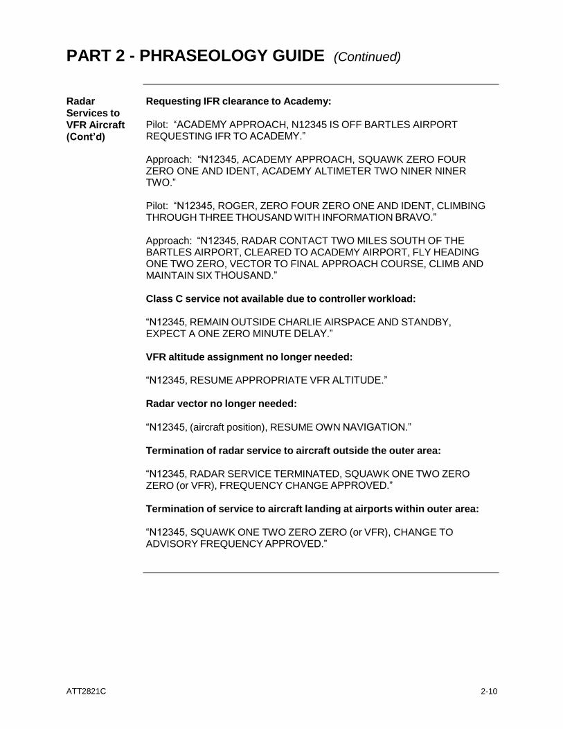
Services to VFR Aircraft (Cont’d)
Requesting IFR clearance to Academy: Pilot: “ACADEMY APPROACH, N12345 IS OFF BARTLES AIRPORT REQUESTING IFR TO ACADEMY.”
Approach: “N12345, ACADEMY APPROACH, SQUAWK ZERO FOUR ZERO ONE AND IDENT, ACADEMY ALTIMETER TWO NINER NINER TWO.”
Pilot: “N12345, ROGER, ZERO FOUR ZERO ONE AND IDENT, CLIMBING THROUGH THREE THOUSAND WITH INFORMATION BRAVO.”
Approach: “N12345, RADAR CONTACT TWO MILES SOUTH OF THE BARTLES AIRPORT, CLEARED TO ACADEMY AIRPORT, FLY HEADING ONE TWO ZERO, VECTOR TO FINAL APPROACH COURSE, CLIMB AND MAINTAIN SIX THOUSAND.”
Class C service not available due to controller workload:
“N12345, REMAIN OUTSIDE CHARLIE AIRSPACE AND STANDBY, EXPECT A ONE ZERO MINUTE DELAY.”
VFR altitude assignment no longer needed:
“N12345, RESUME APPROPRIATE VFR ALTITUDE.”
Radar vector no longer needed:
“N12345, (aircraft position), RESUME OWN NAVIGATION.”
Termination of radar service to aircraft outside the outer area:
“N12345, RADAR SERVICE TERMINATED, SQUAWK ONE TWO ZERO ZERO (or VFR), FREQUENCY CHANGE APPROVED.”
Termination of service to aircraft landing at airports within outer area:
“N12345, SQUAWK ONE TWO ZERO ZERO (or VFR), CHANGE TO ADVISORY FREQUENCY APPROVED.”
ATT2821C
2-11
PART 2 - PHRASEOLOGY GUIDE (Continued)
JKE Tower
Coordination
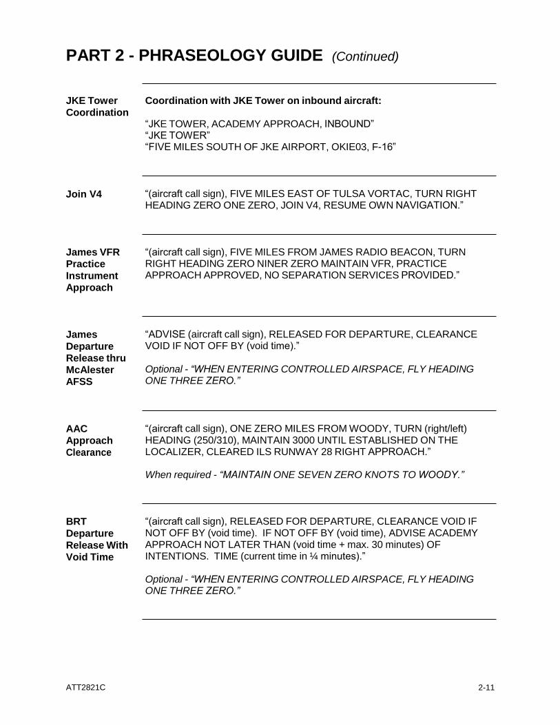
Coordination with JKE Tower on inbound aircraft: “JKE TOWER, ACADEMY APPROACH, INBOUND” “JKE TOWER” “FIVE MILES SOUTH OF JKE AIRPORT, OKIE03, F-16”
Join V4 “(aircraft call sign), FIVE MILES EAST OF TULSA VORTAC, TURN RIGHT
HEADING ZERO ONE ZERO, JOIN V4, RESUME OWN NAVIGATION.”
James VFR Practice
Instrument Approach
“(aircraft call sign), FIVE MILES FROM JAMES RADIO BEACON, TURN RIGHT HEADING ZERO NINER ZERO MAINTAIN VFR, PRACTICE APPROACH APPROVED, NO SEPARATION SERVICES PROVIDED.”
James
Departure Release thru McAlester AFSS
“ADVISE (aircraft call sign), RELEASED FOR DEPARTURE, CLEARANCE VOID IF NOT OFF BY (void time).”
Optional - “WHEN ENTERING CONTROLLED AIRSPACE, FLY HEADING ONE THREE ZERO.”
AAC Approach
Clearance
“(aircraft call sign), ONE ZERO MILES FROM WOODY, TURN (right/left) HEADING (250/310), MAINTAIN 3000 UNTIL ESTABLISHED ON THE LOCALIZER, CLEARED ILS RUNWAY 28 RIGHT APPROACH.”
When required - “MAINTAIN ONE SEVEN ZERO KNOTS TO WOODY.”
BRT
Departure
Release With Void Time
“(aircraft call sign), RELEASED FOR DEPARTURE, CLEARANCE VOID IF NOT OFF BY (void time). IF NOT OFF BY (void time), ADVISE ACADEMY APPROACH NOT LATER THAN (void time + max. 30 minutes) OF INTENTIONS. TIME (current time in ¼ minutes).”
Optional - “WHEN ENTERING CONTROLLED AIRSPACE, FLY HEADING ONE THREE ZERO.”

ATT2821C
2-12
PART 2 - PHRASEOLOGY GUIDE (Continued)
BRT “(aircraft call sign), RELEASED FOR DEPARTURE.”
Departure Release Without Void
Time
Optional - “WHEN ENTERING CONTROLLED AIRSPACE, FLY HEADING ONE THREE ZERO, REPORT AIRBORNE.”
ATT2821C
3-1
AERO ARTCC AND ACADEMY TRACON LETTER OF AGREEMENT
EFFECTIVE DATE: March 19, 2001
SUBJECT: APPROACH CONTROL SERVICE
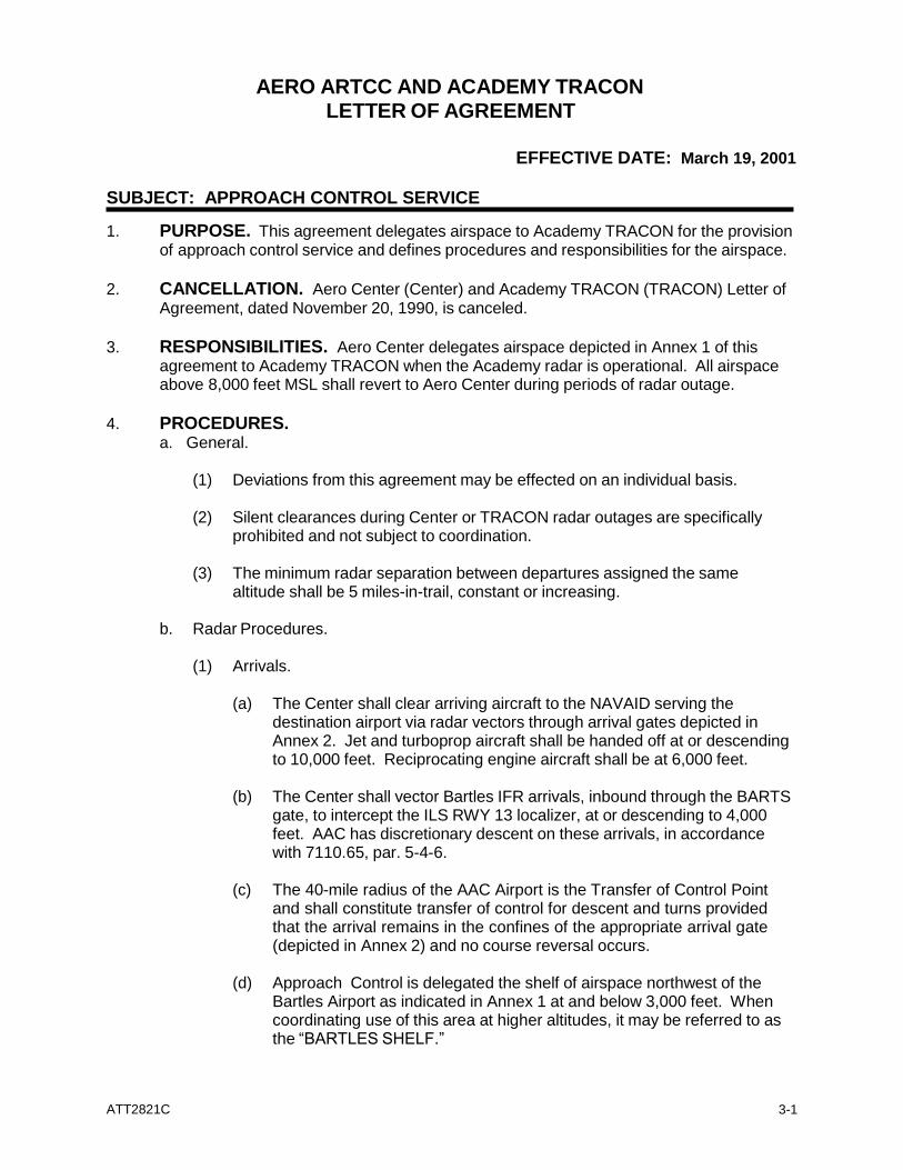
1. PURPOSE. This agreement delegates airspace to Academy TRACON for the provision of approach control service and defines procedures and responsibilities for the airspace.
2. CANCELLATION. Aero Center (Center) and Academy TRACON (TRACON) Letter of
Agreement, dated November 20, 1990, is canceled.
3. RESPONSIBILITIES. Aero Center delegates airspace depicted in Annex 1 of this agreement to Academy TRACON when the Academy radar is operational. All airspace above 8,000 feet MSL shall revert to Aero Center during periods of radar outage.
4. PROCEDURES.
a. General.
(1) Deviations from this agreement may be effected on an individual basis.
(2) Silent clearances during Center or TRACON radar outages are specifically prohibited and not subject to coordination.
(3) The minimum radar separation between departures assigned the same
altitude shall be 5 miles-in-trail, constant or increasing.
b. Radar Procedures.
(1) Arrivals.
(a) The Center shall clear arriving aircraft to the NAVAID serving the destination airport via radar vectors through arrival gates depicted in Annex 2. Jet and turboprop aircraft shall be handed off at or descending to 10,000 feet. Reciprocating engine aircraft shall be at 6,000 feet.
(b) The Center shall vector Bartles IFR arrivals, inbound through the BARTS
gate, to intercept the ILS RWY 13 localizer, at or descending to 4,000 feet. AAC has discretionary descent on these arrivals, in accordance with 7110.65, par. 5-4-6.
(c) The 40-mile radius of the AAC Airport is the Transfer of Control Point
and shall constitute transfer of control for descent and turns provided that the arrival remains in the confines of the appropriate arrival gate (depicted in Annex 2) and no course reversal occurs.
(d) Approach Control is delegated the shelf of airspace northwest of the
Bartles Airport as indicated in Annex 1 at and below 3,000 feet. When coordinating use of this area at higher altitudes, it may be referred to as the “BARTLES SHELF.”
AERO ARTCC AND ACADEMY ATCT
LETTER OF AGREEMENT (Continued)
ATT2821C
3-2
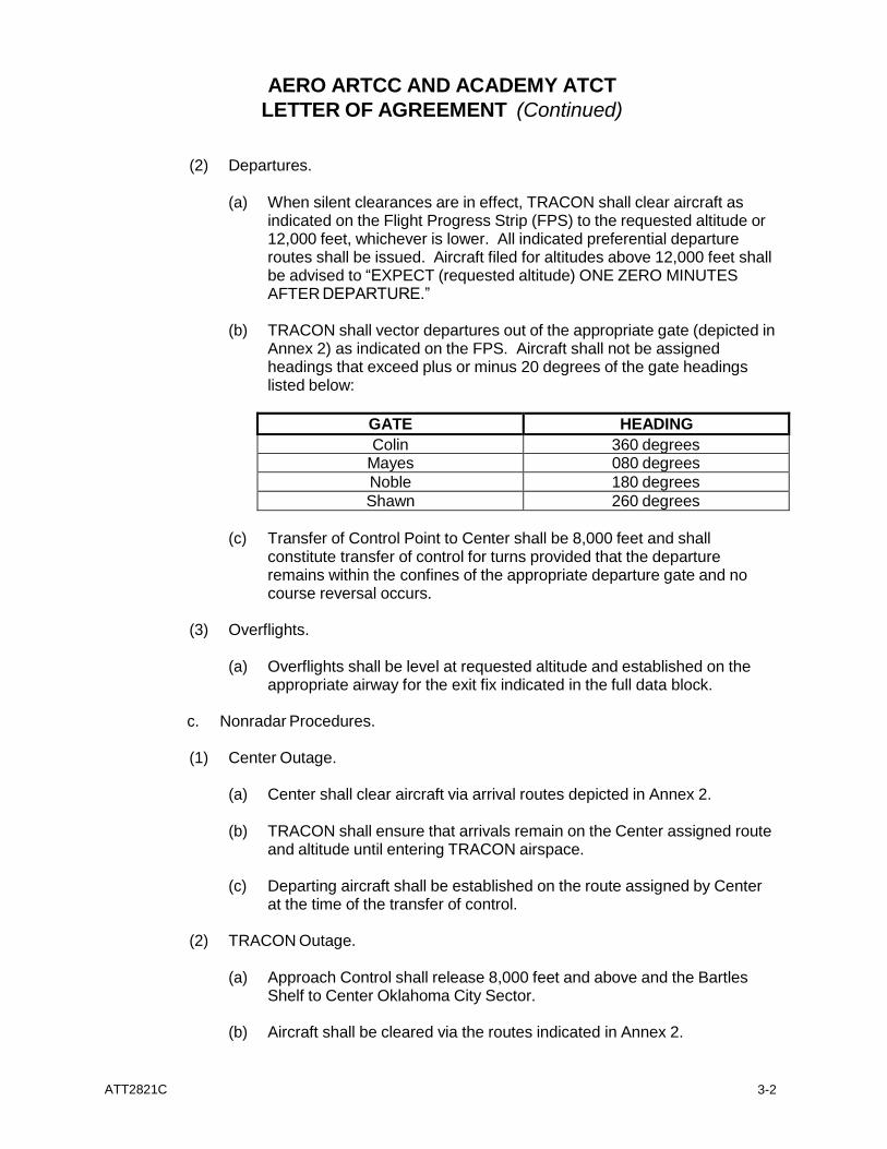
(2) Departures.
(a) When silent clearances are in effect, TRACON shall clear aircraft as indicated on the Flight Progress Strip (FPS) to the requested altitude or 12,000 feet, whichever is lower. All indicated preferential departure routes shall be issued. Aircraft filed for altitudes above 12,000 feet shall be advised to “EXPECT (requested altitude) ONE ZERO MINUTES AFTER DEPARTURE.”
(b) TRACON shall vector departures out of the appropriate gate (depicted in
Annex 2) as indicated on the FPS. Aircraft shall not be assigned headings that exceed plus or minus 20 degrees of the gate headings listed below:
GATE HEADING
Colin 360 degrees Mayes 080 degrees
Noble 180 degrees
Shawn 260 degrees
(c) Transfer of Control Point to Center shall be 8,000 feet and shall constitute transfer of control for turns provided that the departure remains within the confines of the appropriate departure gate and no course reversal occurs.
(3) Overflights.
(a) Overflights shall be level at requested altitude and established on the
appropriate airway for the exit fix indicated in the full data block.
c. Nonradar Procedures.
(1) Center Outage.
(a) Center shall clear aircraft via arrival routes depicted in Annex 2.
(b) TRACON shall ensure that arrivals remain on the Center assigned route and altitude until entering TRACON airspace.
(c) Departing aircraft shall be established on the route assigned by Center
at the time of the transfer of control.
(2) TRACON Outage.
(a) Approach Control shall release 8,000 feet and above and the Bartles Shelf to Center Oklahoma City Sector.
(b) Aircraft shall be cleared via the routes indicated in Annex 2.
AERO ARTCC AND ACADEMY ATCT
LETTER OF AGREEMENT (Continued)
ATT2821C
3-3
(c) Academy arrivals shall be at or descending to 8,000 feet.
(d) Overflights shall be considered coordinated upon receipt of a FPS.
5. ATTACHMENTS.
a. Annex 1 - Academy TRACON Airspace
b. Annex 2 - Arrival and Departure Gates
Edward G. Campbell Kurt D. Roberts Air Traffic Manager Air Traffic Manager Aero Center Academy TRACON
AERO ARTCC AND ACADEMY ATCT
LETTER OF AGREEMENT (Continued)
ATT2821C
3-4
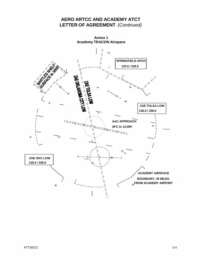
Annex 1
Academy TRACON Airspace
SPRINGFIELD APCH
120.5 / 330.5
ZAE TULSA LOW
136.0 / 336.0
AAC APPROACH
SFC to 12,000'
ZAE OKC LOW
135.0 / 335.0
ACADEMY AIRSPACE
BOUNDARY, 30 MILES
FROM ACADEMY AIRPORT
AERO ARTCC AND ACADEMY ATCT
LETTER OF AGREEMENT (Continued)
ATT2821C
3-5
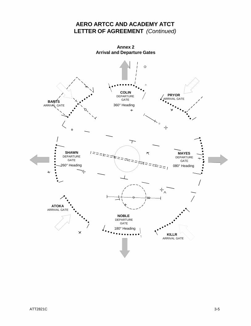
Annex 2
Arrival and Departure Gates
BARTS ARRIVAL GATE
COLIN DEPARTURE
GATE
360° Heading
PRYOR
ARRIVAL GATE
SHAWN DEPARTURE
GATE
260° Heading
MAYES DEPARTURE
GATE
080° Heading
ATOKA
ARRIVAL GATE
NOBLE DEPARTURE
GATE
180° Heading
KILLR
ARRIVAL GATE
ATT2821C
3-7
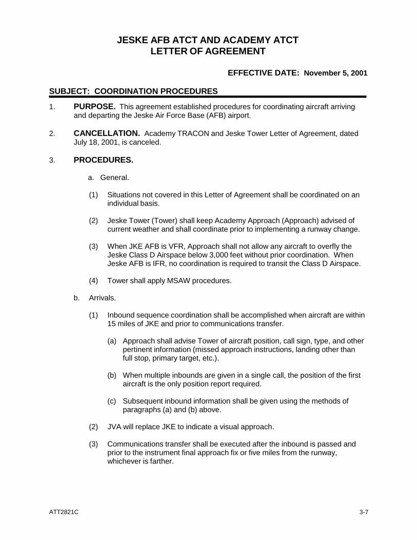
JESKE AFB ATCT AND ACADEMY ATCT LETTER OF AGREEMENT
EFFECTIVE DATE: November 5, 2001
SUBJECT: COORDINATION PROCEDURES
1. PURPOSE. This agreement established procedures for coordinating aircraft arriving and departing the Jeske Air Force Base (AFB) airport.
2. CANCELLATION. Academy TRACON and Jeske Tower Letter of Agreement, dated
July 18, 2001, is canceled.
3. PROCEDURES.
a. General.
(1) Situations not covered in this Letter of Agreement shall be coordinated on an individual basis.
(2) Jeske Tower (Tower) shall keep Academy Approach (Approach) advised of
current weather and shall coordinate prior to implementing a runway change.
(3) When JKE AFB is VFR, Approach shall not allow any aircraft to overfly the Jeske Class D Airspace below 3,000 feet without prior coordination. When Jeske AFB is IFR, no coordination is required to transit the Class D Airspace.
(4) Tower shall apply MSAW procedures.
b. Arrivals.
(1) Inbound sequence coordination shall be accomplished when aircraft are within
15 miles of JKE and prior to communications transfer.
(a) Approach shall advise Tower of aircraft position, call sign, type, and other pertinent information (missed approach instructions, landing other than full stop, primary target, etc.).
(b) When multiple inbounds are given in a single call, the position of the first
aircraft is the only position report required.
(c) Subsequent inbound information shall be given using the methods of paragraphs (a) and (b) above.
(2) JVA will replace JKE to indicate a visual approach.
(3) Communications transfer shall be executed after the inbound is passed and
prior to the instrument final approach fix or five miles from the runway, whichever is farther.
ATT2821C
3-8
ACADEMY ATCT AND JESKE AFB ATCT LETTER OF AGREEMENT (Continued)
(4) Tower shall advise Approach of any aircraft executing an unplanned missed
approach. Unless otherwise instructed by Approach, Tower shall assign 3,000 feet and 240° or 120° for Runways 27 and 09, respectively.
c. Departures.
(1) Silent clearances are in effect during periods when the radar and FDIO are
operational. Tower shall assign the routing indicated on the departure strip and the requested altitude or 4,000 feet, whichever is lower. Aircraft requesting 5,000 feet and above shall be advised to “EXPECT (requested altitude) ONE ZERO MINUTES AFTER DEPARTURE.”
(2) Tower is authorized to automatically release departures off the active runway
heading. Automatic releases shall be canceled when the radar or BRITE is out of service. To terminate automatic releases, Approach shall state “CALL FOR RELEASE.” When automatic releases are not in effect, Tower shall assign runway heading unless directed otherwise by Approach.
(3) Tower shall provide initial separation between successive departures and
between departures and arrivals inside Class D Airspace.
(4) Tower shall advise Approach when an aircraft begins takeoff roll.
(5) Approach shall not issue a heading resulting in a turn of more than 90 degrees prior to the aircraft reaching 3,000 feet.
James J. Williams, Maj. USAF Kurt D. Roberts Commander, 1926th Air Traffic Manager Communications Squadron Academy TRACON
ATT2821C
3-9
SPRINGFIELD ATCT AND ACADEMY ATCT
LETTER OF AGREEMENT
EFFECTIVE DATE: January 31, 2002
SUBJECT: TOWER EN ROUTE CONTROL
1. PURPOSE. This agreement establishes procedures for tower en route control service between Academy TRACON and Springfield Tower in the airspace depicted in Annex 1.
2. CANCELLATION. Springfield Tower and Academy TRACON Letter of Agreement,
dated September 21, 1991, is canceled.
3. PROCEDURES. a. When either facility experiences a radar or FDIO outage, aircraft shall be
coordinated on an individual basis.
b. Arrival aircraft shall be established on V4 prior to the lateral airspace boundary depicted in Annex 1. Aircraft landing in Academy airspace shall be cleared to the destination airport via V4, Pryor, then direct to the navigational aid serving the airport.
c. Aircraft entering the receiving facility’s airspace shall be on the route and level at
the altitude indicated on the FDIO strip unless otherwise coordinated. Aircraft filed for the same altitude shall be separated by 5 miles constant or increasing in trail.
(1) Aircraft entering Academy airspace area are level at 6,000 or 8,000 feet MSL.
(2) Aircraft entering Springfield airspace area are level at 5,000 or 7,000 feet
MSL.
d. When either facility experiences ARTS failure, the receiving facility shall specify beacon codes.
e. For arrival aircraft, the Transfer of Control Point (TCP) shall constitute transfer of
control for descent and/or turns of up to 30 degrees. For Academy arrivals, the TCP is defined as the 40-mile fix on V4. For Springfield arrivals, the TCP is the Pryor intersection.
4. ATTACHMENTS.
a. Annex 1 - Springfield Airspace
Carlotta W. Andresen Kurt D. Roberts Air Traffic Manager Air Traffic Manager Springfield Tower Academy TRACON
ATT2821C
3-10
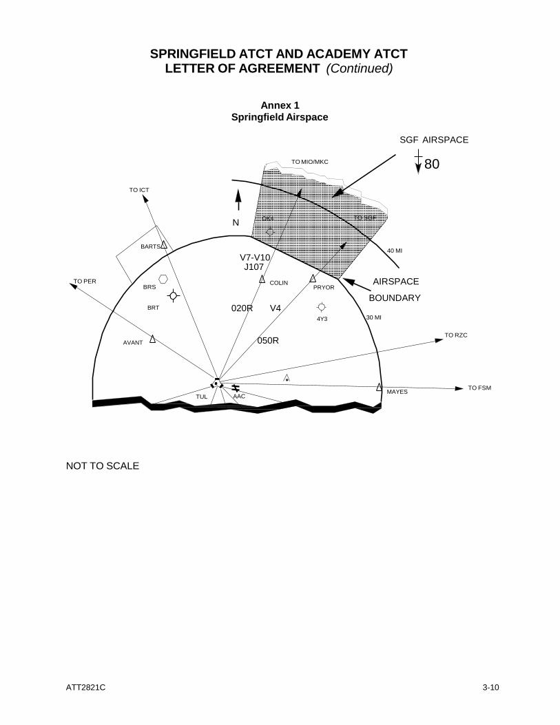
SPRINGFIELD ATCT AND ACADEMY ATCT
LETTER OF AGREEMENT (Continued)
Annex 1 Springfield Airspace
TO MIO/MKC
SGF AIRSPACE
80
TO ICT
N OK4 TO SGF
TO PER
BARTS
BRS
V7-V10 J107
COLIN
PRYOR
40 MI
AIRSPACE
BOUNDARY BRT 020R V4
4Y3
30 MI
AVANT
050R TO RZC
TUL AAC
MAYES
TO FSM
V4 205
NOT TO SCALE
ATT2821C
3-11
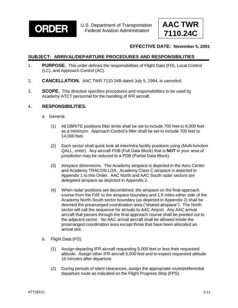
U.S. Department of Transportation Federal Aviation Administration
AAC TWR 7110.24C
EFFECTIVE DATE: November 5, 2001
SUBJECT: ARRIVAL/DEPARTURE PROCEDURES AND RESPONSIBILITIES
1. PURPOSE. This order defines the responsibilities of Flight Data (FD), Local Control (LC), and Approach Control (AC).
2. CANCELLATION. AAC TWR 7110.24B dated July 5, 1994, is canceled.
3. SCOPE. This directive specifies procedures and responsibilities to be used by
Academy ATCT personnel for the handling of IFR aircraft.
4. RESPONSIBILITIES.
a. General.
(1) All DBRITE positions filter limits shall be set to include 700 feet to 6,000 feet as a minimum. Approach Control’s filter shall be set to include 700 feet to 14,000 feet.
(2) Each sector shall quick look all inter/intra facility positions using (Multi-function
QALL, enter). Any aircraft FDB (Full Data Block) that is NOT in your area of jurisdiction may be reduced to a PDB (Partial Data Block).
(3) Airspace dimensions. The Academy airspace is depicted in the Aero Center
and Academy TRACON LOA. Academy Class C airspace is depicted in Appendix 1 to this Order. AAC North and AAC South radar sectors are delegated airspace as depicted in Appendix 2.
(4) When radar positions are decombined, the airspace on the final approach
course from the FAF to the airspace boundary and 1.5 miles either side of the Academy North-South sector boundary (as depicted in Appendix 2) shall be deemed the prearranged coordination area (“shared airspace”). The North sector will call the sequence for arrivals to AAC Airport. Any AAC arrival aircraft that passes through the final approach course shall be pointed out to the adjacent sector. No AAC arrival aircraft shall be allowed inside the prearranged coordination area except those that have been allocated an arrival slot.
b. Flight Data (FD).
(1) Assign departing IFR aircraft requesting 5,000 feet or less their requested
altitude. Assign other IFR aircraft 5,000 feet and to expect requested altitude 10 minutes after departure.
(2) During periods of silent clearances, assign the appropriate route/preferential
departure route as indicated on the Flight Progress Strip (FPS).
ATT2821C
3-12
ORDER 7110.24C (Continued)
(3) Ensure departure messages are passed to Aero Center manually or via the FDIO equipment for nonbeacon or nondiscrete code assigned aircraft.
(4) Obtain and record heading/destination of VFR departures and prepare an FPS. VFR
traffic remaining in the pattern shall be assigned a code of 1200.
(5) Enter VFR departures into the ARTS using a computer-assigned code in the 0300 series.
(6) Enter Local IFR/SVFR into the ARTS.
(7) Enter area weather into the environmental display system.
(8) Issue aircraft departing satellite airports a clearance as filed; assign an altitude of
3,000 feet to expect requested altitude ten minutes after departure, and assign the appropriate beacon code and departure frequency. Releases will be coordinated by McAlester Radio on an individual basis with the appropriate radar controller, except at Bartles where the aircraft will be told to hold for release and to contact the appropriate controller when ready for departure. When VOID times are relayed from the releasing controller to McAlester AFSS, McAlester will issue clearances to include the statement, “If not off by (VOID TIME), advise NLT (VOID TIME plus 30 minutes) of intentions.”
c. Local Control (LC).
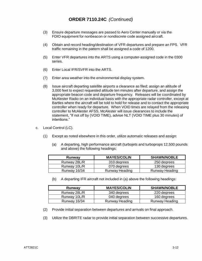
(1) Except as noted elsewhere in this order, utilize automatic releases and assign:
(a) A departing, high performance aircraft (turbojets and turboprops 12,500 pounds
and above) the following headings:
Runway MAYES/COLIN SHAWN/NOBLE
Runway 28L/R 310 degrees 250 degrees Runway 10L/R 070 degrees 130 degrees
Runway 16/34 Runway Heading Runway Heading
(b) A departing IFR aircraft not included in (a) above the following headings:
Runway MAYES/COLIN SHAWN/NOBLE
Runway 28L/R 340 degrees 220 degrees Runway 10L/R 040 degrees 160 degrees
Runway 16/34 Runway Heading Runway Heading
(2) Provide initial separation between departures and arrivals on final approach.
(3) Utilize the DBRITE radar to provide initial separation between successive departures.
ATT2821C
3-13
ORDER 7110.24C (Continued)
(4) Tower need not notify Departure Control when aircraft depart; however, tower shall advise Departure Control of any departure that has not auto-acquired within one mile of the departing runway end. This coordination shall be initiated prior to the aircraft reaching two miles from runway end.
(5) When the radar or DBRITE is out of service or when automatic releases have been
canceled for any reason, call the appropriate radar sector for release on all departures.
(6) Issue altitude restrictions assigned by the radar controller and other restrictions as
necessary for separation or efficiency. Advise the radar controller via interphone or scratchpad of restrictions not initiated by the radar team.
(7) Assign unplanned missed approaches runway heading and altitude of 3,000 feet and
coordinate with Approach Control (AC).
(8) Monitor DBRITE for arrivals.
(9) Do not allow traffic in the local pattern to operate above 1,600 feet without coordination with AC.
(10) LC has the authority to change the landing runway as long as it does not effect the
approach sequence.
(11) Coordinate pop-up VFR/IFR aircraft with AC.
(12) Issue radar traffic advisories or safety alerts to all aircraft under LC jurisdiction.
(13) Ensure that departing aircraft’s ARTS scratchpads indicate the appropriate departure gate (i.e. COL, MAY, NOB, SHA). If the aircraft will remain at or below 12,000 feet, modify the scratchpad to show the altitude in thousands of feet (i.e. C11, S12, M07, N08).
(14) Advise AAC North of ATIS code change.
d. Approach Control.
(1) Ensure that pertinent information is indicated in the full data block of all arrival aircraft
before the aircraft is frequency changed to the Tower. The inbound to Tower is passed via the quick look function of the ARTS.
(2) Manually pass aircraft call sign and sequence when the radar or DBRITE is out of
service.
(3) AAC North shall advise AAC South of ATIS code change. Both North and South shall broadcast ATIS code change to all aircraft.
ATT2821C
3-14
ORDER 7110.24C (Continued)
(4) Ensure aircraft have a complete data block prior to frequency change and prior to reaching a point 5 miles from the airport. Aircraft shall be on the tower frequency prior to the final approach fix or 5 miles from the airport, but not outside the 15-mile range mark. Scratchpad ARTS entries shall be as follows:
(a) IFR aircraft: *VAR will replace AAC to indicate a visual approach to RY28R
*VAL will replace AAC to indicate a visual approach to RY28L *BVA will replace BRT to indicate a visual approach to BRT *YVA will replace 4Y3 to indicate a visual approach to 4Y3 *VVA will replace 4V4 to indicate a visual approach to 4V4 *JVA will replace JKE to indicate a visual approach to JKE
(b) VFR aircraft: *28L, *28R (or other non-ATIS runway as appropriate) or *ILS if on
a practice approach.
(5) Conform to the airport noise abatement program and do not issue a turn to a departure/missed approach prior to the aircraft reaching 3,000 feet or a point 3 miles from the departure end of the runway. All IFR or VFR turbojet aircraft, regardless of weight, and turboprop aircraft weighing more than 12,500 shall conform to noise abatement procedures. IFR/VFR reciprocating and turboprop aircraft weighing 12,500 or less shall be exempt from noise abatement procedures.
(6) Do not allow aircraft under AC jurisdiction to operate within 5 miles of the airport
below 2,100 feet without prior coordination with the tower.
(7) Assign departures requiring intrafacility handoff 12,000 feet or requested altitude, whichever is lower.
(8) The receiving controller shall have control for turns up to 30 degrees on departures
and overflights transitioning from sector to sector. The transferring controller is not required to forward headings to the receiving controller.
(9) Arrivals transitioning from sector to sector shall be vectored outside the 15-mile range
ring (east or west) and assigned 6,000 feet. The receiving controller shall have control for turns up to 30 degrees. The transferring controller is not required to forward headings to the receiving controller.
(10) a) VFR arrivals from AAC North will land RY28R unless coordinated with AAC South.
b) VFR arrivals from AAC South will land RY28L unless coordinated with AAC North.
(11) Issue appropriate departure restrictions to tower and cancel restrictions when no
longer needed.
(12) Coordinate with LC on the position of any departure whose radar identification is questionable.
(13) Ensure that a manual departure message is passed to Aero Center on aircraft with a
flashing “DM” in the data block.
ATT2821C
3-15
ORDER 7110.24C (Continued)
e. Class D.
(1) Departure release shall be automatic for all runways unless canceled by the appropriate arrival/departure controller.
(2) Local Control is responsible for initial separation of Class D departures from aircraft in
the local pattern.
(3) After meeting noise abatement procedures, Local Control shall assign the pilot- requested headings and altitudes to VFR departures except:
(a) Assign alternate headings as needed to provide initial separation and coordinate
with the appropriate sector.
(b) Do not assign headings which will cross the final approach course.
(4) When working conditions dictate, Approach Control may state “CLASS D DEPARTURES STRAIGHT OUT.” In this case, LC shall issue Class D departure headings consistent with procedures for IFR departures.
4. ATTACHMENTS.
a. Appendix 1 - Academy Class D and Class E Airspace
b. Appendix 2 - North-South Airspace
c. Appendix 3 - Academy Video Map
Kurt D. Roberts Air Traffic Manager Academy TRACON
ATT2821C
3-16
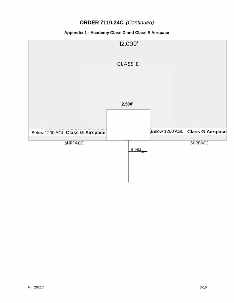
ORDER 7110.24C (Continued)
Appendix 1 - Academy Class D and Class E Airspace
Below 1200’AGL Class G Airspace Below 1200’AGL Class G Airspace
2,500’
ATT2821C
3-17
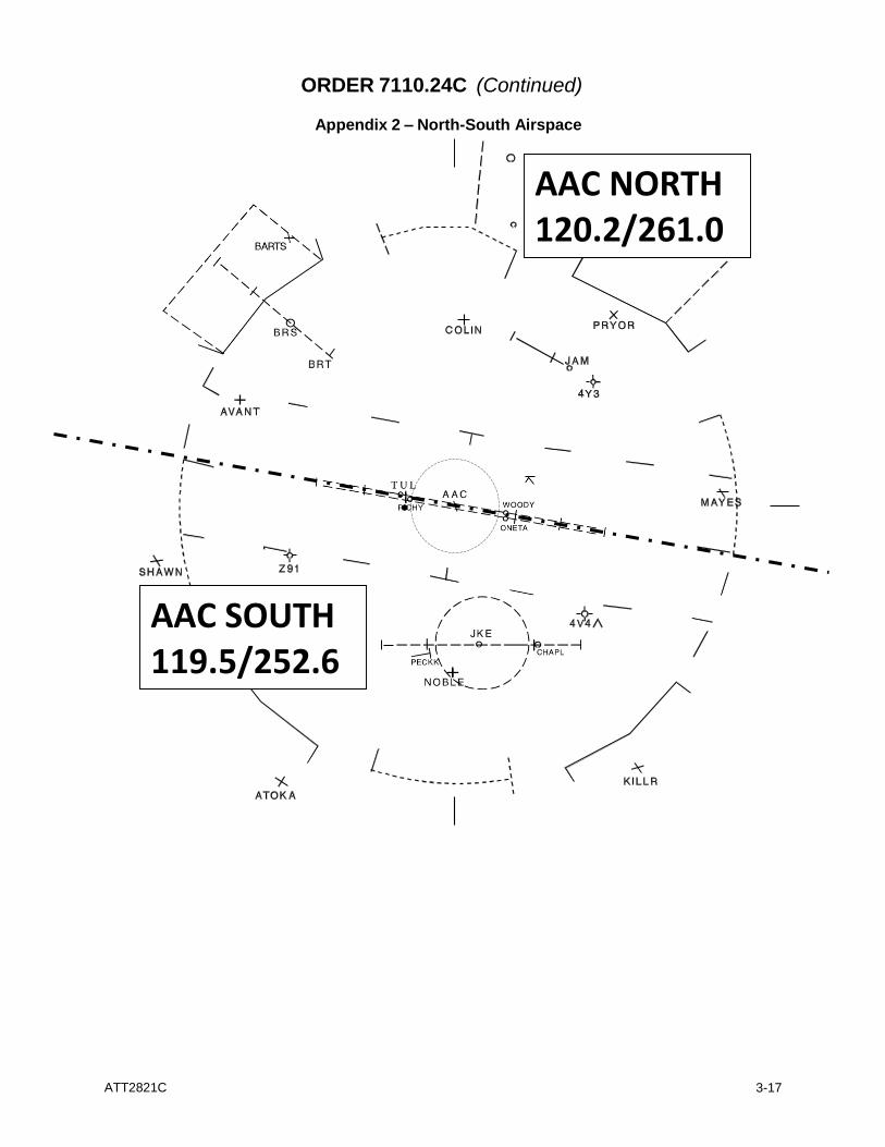
ORDER 7110.24C (Continued)
Appendix 2 – North-South Airspace
AAC NORTH 120.2/261.0
AAC SOUTH 119.5/252.6
ATT2821C
3-18
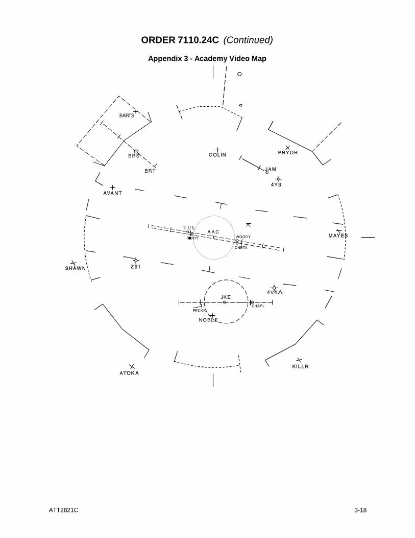
ORDER 7110.24C (Continued)
Appendix 3 - Academy Video Map
ATT2821C
3-19
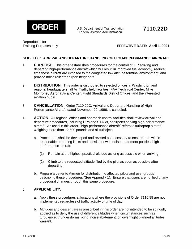
U.S. Department of Transportation
Federal Aviation Administration
7110.22D
Reproduced for Training Purposes only EFFECTIVE DATE: April 1, 2001
SUBJECT: ARRIVAL AND DEPARTURE HANDLING OF HIGH-PERFORMANCE AIRCRAFT
1. PURPOSE. This order establishes procedures for the control of IFR arriving and departing high-performance aircraft which will result in improved fuel economy, reduce time these aircraft are exposed to the congested low altitude terminal environment, and provide noise relief for airport neighbors.
2. DISTRIBUTION. This order is distributed to selected offices in Washington and
regional headquarters, all Air Traffic field facilities, FAA Technical Center, Mike Monroney Aeronautical Center, Flight Standards District Offices, and the interested aviation public.
3. CANCELLATION. Order 7110.22C, Arrival and Departure Handling of High-
Performance Aircraft, dated November 20, 1996, is canceled. 4. ACTION. All regional offices and approach control facilities shall review arrival and
departure procedures, including DPs and STARs, at airports serving high-performance aircraft. As used in this order, “high-performance aircraft” refers to turboprop aircraft weighing more than 12,500 pounds and all turbojets.
a. Procedures shall be developed and revised as necessary to ensure that, within
reasonable operating limits and consistent with noise abatement policies, high- performance aircraft:
(1) Remain at the highest practical altitude as long as possible when arriving.
(2) Climb to the requested altitude filed by the pilot as soon as possible after
departing.
b. Prepare a Letter to Airmen for distribution to affected pilots and user groups describing these procedures (See Appendix 1). Ensure that users are notified of any procedural changes through this same procedure.
5. APPLICABILITY.
a. Apply these procedures at locations where the provisions of Order 7110.88 are not
implemented regardless of traffic activity or time of day.
b. Altitudes and descent areas prescribed in this order are not intended to be so rigidly applied as to deny the use of different altitudes when circumstances such as turbulence, thunderstorms, icing, noise abatement, or lower flight planned altitudes warrant.
ATT2821C
3-20
6. PROCEDURES.
a. Arriving aircraft should enter the terminal area at or above 10,000 feet Above Airport
Elevation (AAE) and remain at that altitude as long as feasible. Descent should commence no greater than 40 flying miles nor less than 30 flying miles from the airport. Descent below 5,000 feet AAE shall be limited to the designated descent area unless the pilot has indicated an operational need for a lower altitude (See paragraph 5b).
b. Arrival delays should be absorbed at altitudes at or above 10,000 feet AAE.
c. Ensure uninterrupted climbs to departing aircraft and avoid assigning altitudes below
5,000 feet AAE when possible.
d. Avoid assigning VFR cruising altitudes. 7. EXCEPTIONS.
a. These procedures do not apply to ARTCCs or in a nonradar environment; however,
where practical, the intent of this order should be complied with.
b. These procedures are not applicable to aircraft after they have entered Class B airspace. At those locations where high-performance aircraft frequently operate below 5,000 feet AAE prior to entering Class B airspace, routes and altitudes should be published on the Class B area chart.
c. Military ATC facilities are exempt from these procedures unless compliance is
directed by their respective service. 8. MISCELLANEOUS.
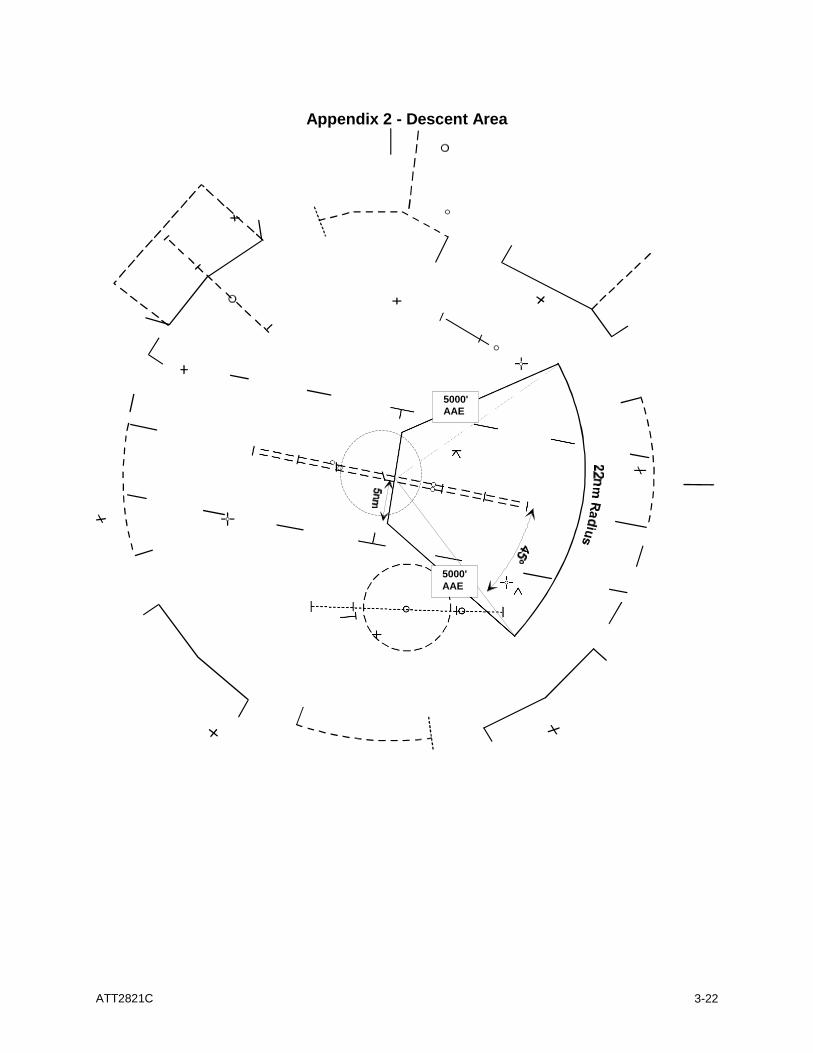
a. A typical descent area is depicted in Appendix 2.
b. Descent areas may be modified at Class C airspace locations.
c. These guidelines are necessarily broad and should be tempered with good
judgment. They are not intended to be so inflexible that safety could be jeopardized.
John R. Ryan Director, Air Traffic Operations Service
Distribution: ZAT-710 (minus military) Initiated By: AJL-512
special military distribution
ATT2821C
3-21
1/16/06 APPENDIX 1. LETTER TO AIRMEN
DEPARTMENT OF TRANSPORTATION
FEDERAL AVIATION ADMINISTRATION ACADEMY AIRPORT TULSA, OKLAHOMA
ISSUED:
1/1/06
EFFECTIVE:
1/16/06
ACADEMY APPROACH LETTER TO AIRMEN NUMBER 12345.
SUBJECT: DESCENT PROCEDURES FOR HIGH PERFORMANCE AIRCRAFT
CANCELLATION: 1/16/08
A new procedure will be started at Academy Approach on 1/16/06. We hope that a cooperative effort on the part of all pilots will help to improve the degree of safety in our airport environment. Furthermore, this program is designed to provide noise relief to our airport neighbors. A recent near midair collision study indicates that the most hazardous mix of controlled and uncontrolled aircraft occurs within a radius of approximately 15 miles of the airport and at altitudes up to and including 4,000 feet AAE.
This new procedure is intended to reduce, as much as possible, the exposure of high- performance airplanes to uncontrolled aircraft. To the extent possible, inbound IFR airplanes will be kept at 6,000 MSL or higher until further descent is required.
We hope that pilot cooperation will help us, in some measure, to segregate turbojet airplanes from uncontrolled aircraft. This procedure has been established for instrument approaches, but should work equally well for aircraft operating VFR. Normally the high-performance airplanes will follow these prescribed flight paths; and, if the uncontrolled aircraft avoid these areas as much as possible, exposure will be reduced. Reduction of exposure should improve safety, which is our primary concern. We solicit your cooperation in making these procedures work so that total effectiveness may be realized.
Dennis Hughes Air Traffic Manager Academy Approach
NOTE: Air Traffic Managers should attach to this bulletin a map of their local area depicting descent areas and the most heavily traveled IFR routes or radar vector paths to the descent areas.
ATT2821C
3-22
Appendix 2 - Descent Area
5000'
AAE
5000'
AAE
ATT2821C
3-23
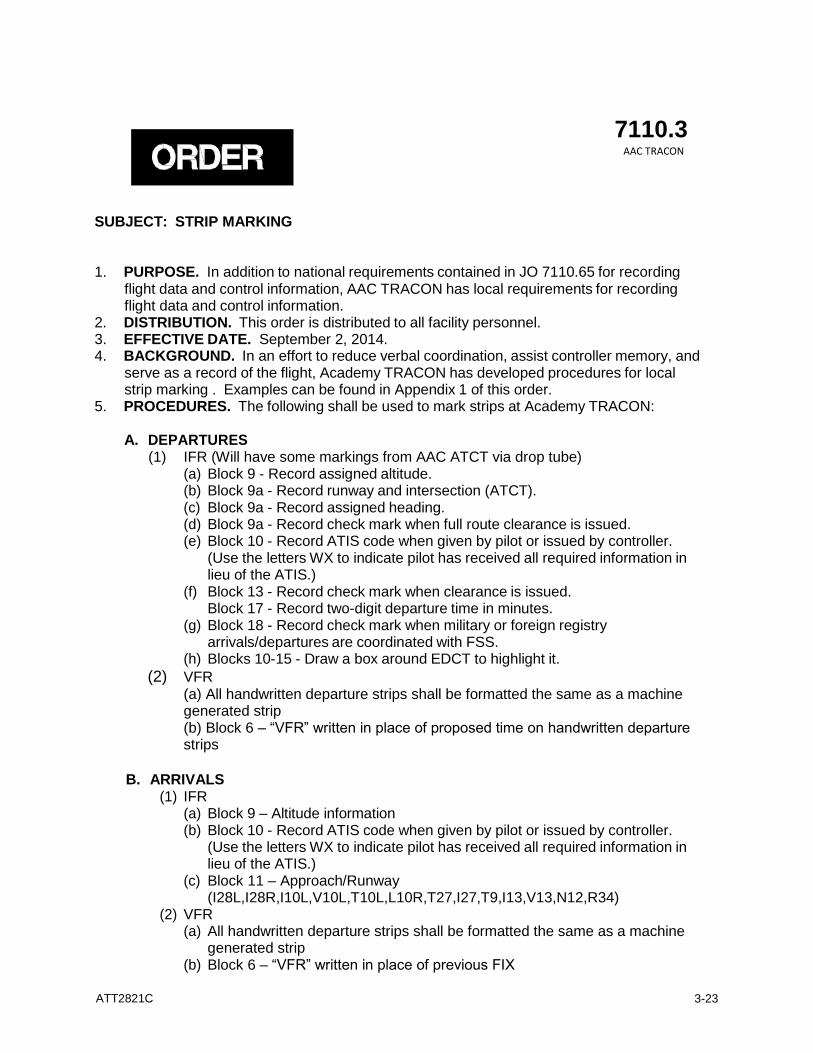
ORDER
7110.3 AAC TRACON
SUBJECT: STRIP MARKING
1. PURPOSE. In addition to national requirements contained in JO 7110.65 for recording
flight data and control information, AAC TRACON has local requirements for recording flight data and control information.
2. DISTRIBUTION. This order is distributed to all facility personnel. 3. EFFECTIVE DATE. September 2, 2014. 4. BACKGROUND. In an effort to reduce verbal coordination, assist controller memory, and
serve as a record of the flight, Academy TRACON has developed procedures for local strip marking . Examples can be found in Appendix 1 of this order.
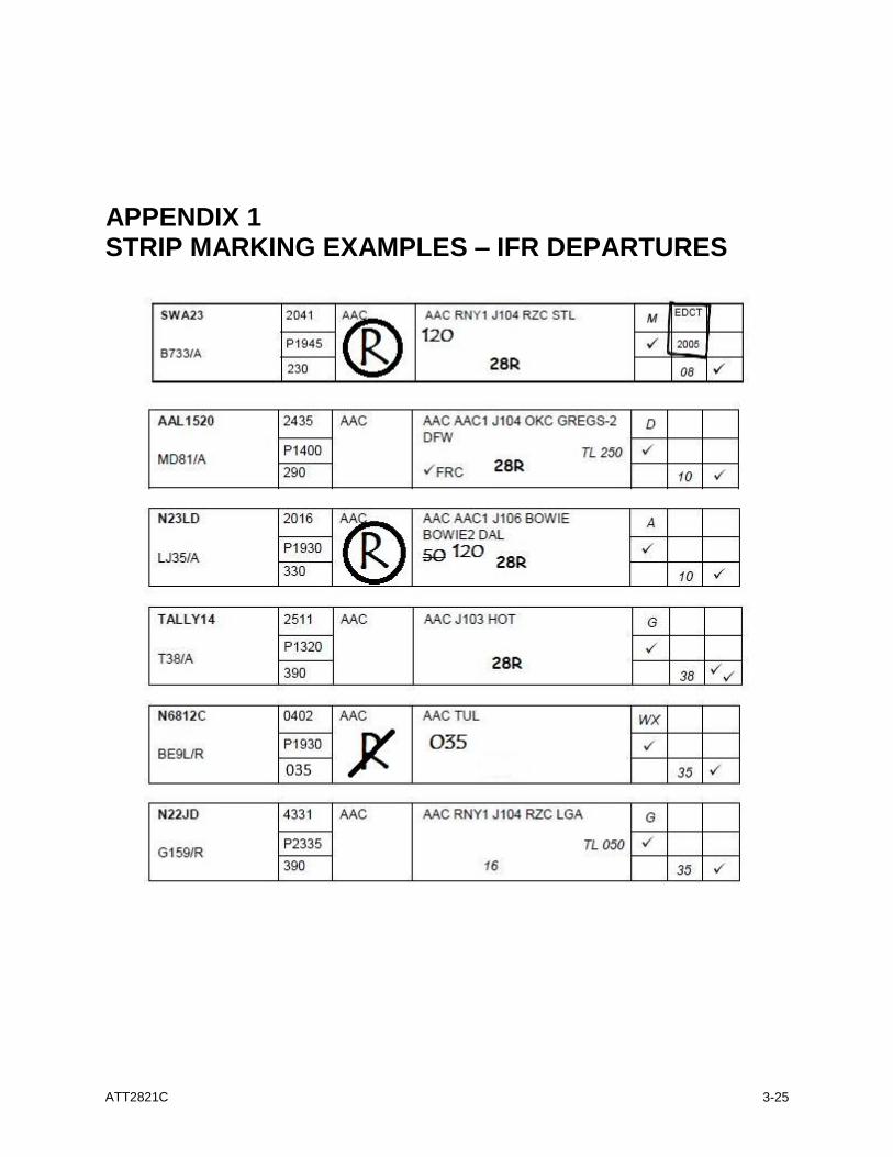
5. PROCEDURES. The following shall be used to mark strips at Academy TRACON:
A. DEPARTURES (1) IFR (Will have some markings from AAC ATCT via drop tube)
(a) Block 9 - Record assigned altitude. (b) Block 9a - Record runway and intersection (ATCT). (c) Block 9a - Record assigned heading. (d) Block 9a - Record check mark when full route clearance is issued. (e) Block 10 - Record ATIS code when given by pilot or issued by controller.
(Use the letters WX to indicate pilot has received all required information in lieu of the ATIS.)
(f) Block 13 - Record check mark when clearance is issued. Block 17 - Record two-digit departure time in minutes.
(g) Block 18 - Record check mark when military or foreign registry arrivals/departures are coordinated with FSS.
(h) Blocks 10-15 - Draw a box around EDCT to highlight it.
(2) VFR
(a) All handwritten departure strips shall be formatted the same as a machine generated strip (b) Block 6 – “VFR” written in place of proposed time on handwritten departure strips
B. ARRIVALS
(1) IFR (a) Block 9 – Altitude information (b) Block 10 - Record ATIS code when given by pilot or issued by controller.
(Use the letters WX to indicate pilot has received all required information in lieu of the ATIS.)
(c) Block 11 – Approach/Runway (I28L,I28R,I10L,V10L,T10L,L10R,T27,I27,T9,I13,V13,N12,R34)
(2) VFR (a) All handwritten departure strips shall be formatted the same as a machine
generated strip (b) Block 6 – “VFR” written in place of previous FIX
ATT2821C
3-24
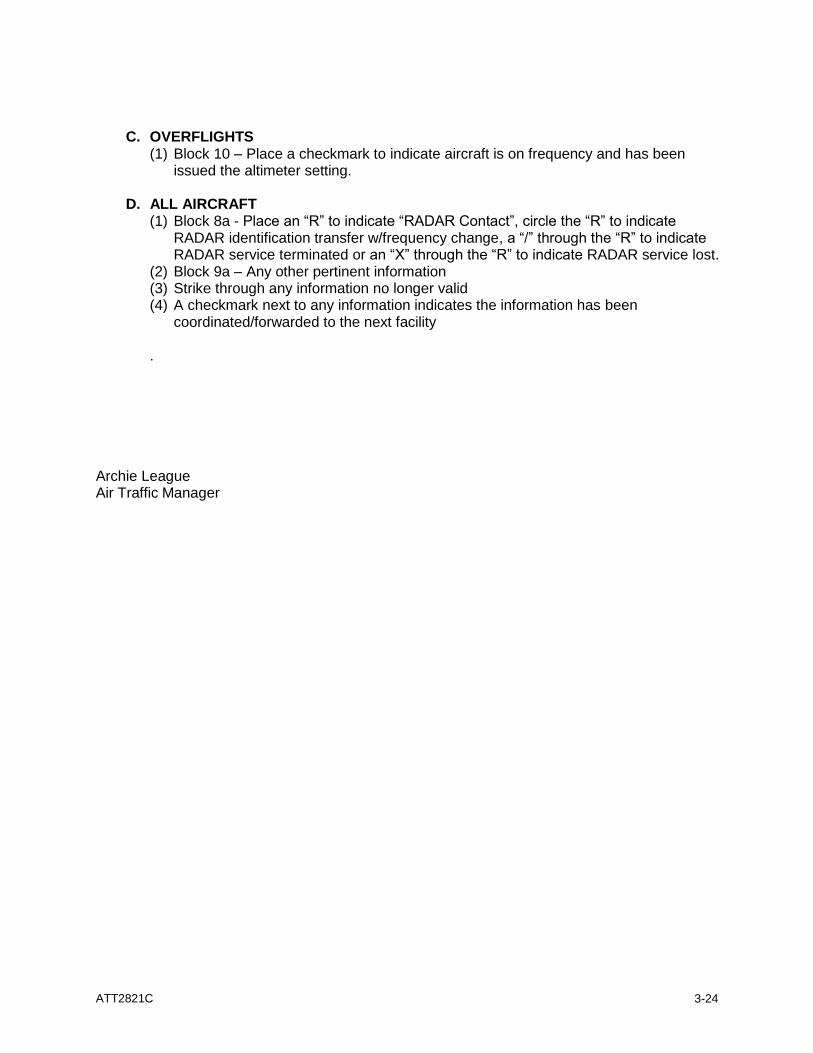
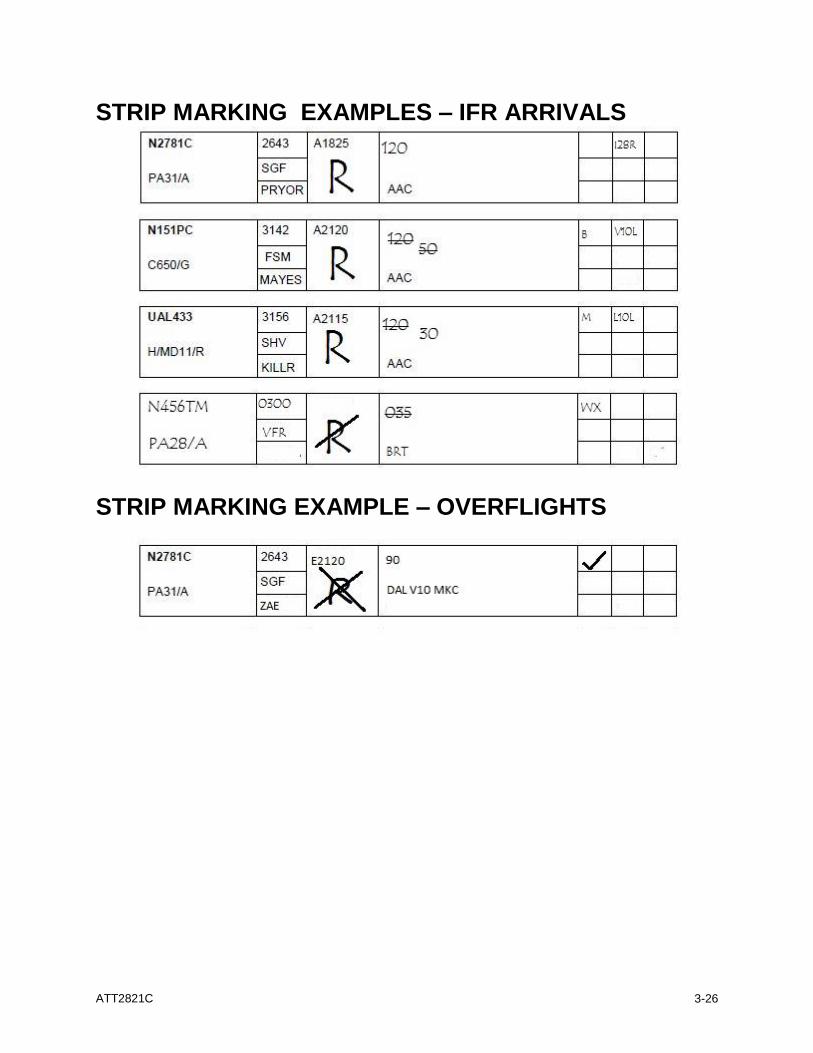
C. OVERFLIGHTS
(1) Block 10 – Place a checkmark to indicate aircraft is on frequency and has been issued the altimeter setting.
D. ALL AIRCRAFT
(1) Block 8a - Place an “R” to indicate “RADAR Contact”, circle the “R” to indicate RADAR identification transfer w/frequency change, a “/” through the “R” to indicate RADAR service terminated or an “X” through the “R” to indicate RADAR service lost.
(2) Block 9a – Any other pertinent information (3) Strike through any information no longer valid (4) A checkmark next to any information indicates the information has been
coordinated/forwarded to the next facility
.
Archie League Air Traffic Manager
ATT2821C
3-25
APPENDIX 1 STRIP MARKING EXAMPLES – IFR DEPARTURES
ATT2821C
3-26
STRIP MARKING EXAMPLES – IFR ARRIVALS
STRIP MARKING EXAMPLE – OVERFLIGHTS
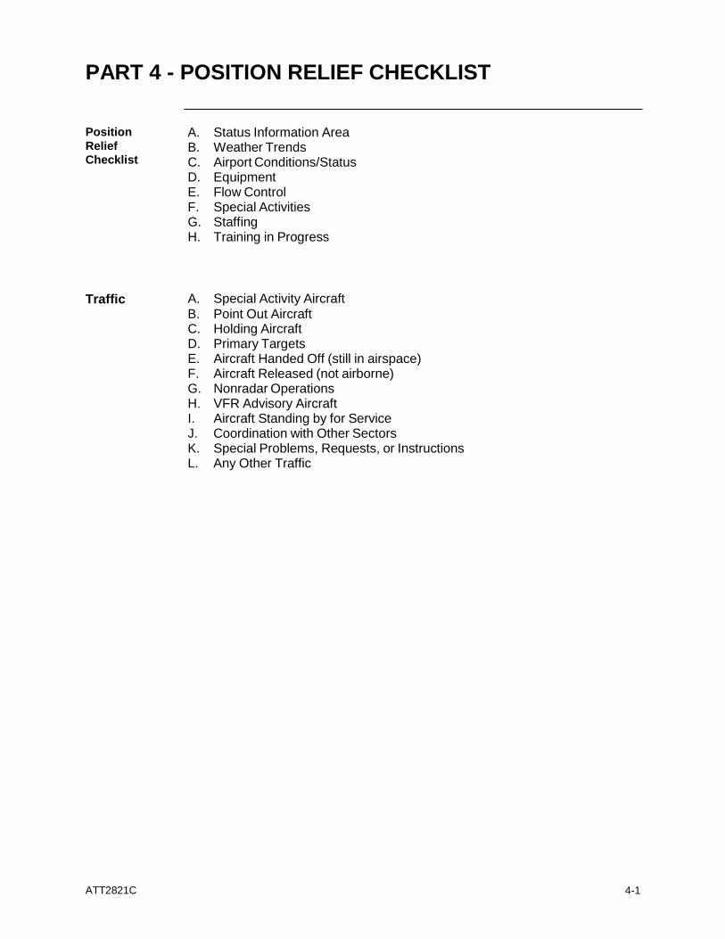
PART 4 - POSITION RELIEF CHECKLIST
ATT2821C
4-1
Position
Relief Checklist
A. Status Information Area B. Weather Trends C. Airport Conditions/Status D. Equipment E. Flow Control F. Special Activities G. Staffing H. Training in Progress
Traffic A. Special Activity Aircraft B. Point Out Aircraft C. Holding Aircraft D. Primary Targets E. Aircraft Handed Off (still in airspace) F. Aircraft Released (not airborne) G. Nonradar Operations H. VFR Advisory Aircraft I. Aircraft Standing by for Service J. Coordination with Other Sectors K. Special Problems, Requests, or Instructions L. Any Other Traffic
PART 5 – ACADEMY APPROACH PLATES
ATT2821C
5-1
PART 5 – ACADEMY APPROACH PLATES
ATT2821C
5-2
PART 5 – ACADEMY APPROACH PLATES
ATT2821C
5-3
PART 5 – ACADEMY APPROACH PLATES
ATT2821C
5-4
PART 5 – ACADEMY APPROACH PLATES
ATT2821C
5-5
PART 5 – ACADEMY APPROACH PLATES
ATT2821C
5-6
PART 5 – ACADEMY APPROACH PLATES
ATT2821C
5-7
PART 5 – ACADEMY APPROACH PLATES
ATT2821C
5-8
PART 5 – ACADEMY APPROACH PLATES
ATT2821C
5-9
PART 5 – ACADEMY APPROACH PLATES
ATT2821C
5-10
PART 5 – ACADEMY APPROACH PLATES
ATT2821C
5-11
Viney (4V4) Runway 16 Departure Procedure
On departure, fly heading 190 until reaching 1,800 MSL, then proceed
on course.
PART 5 – ACADEMY APPROACH PLATES
ATT2821C
6-1
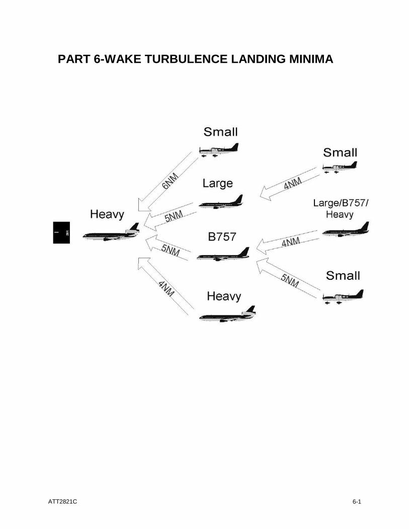
PART 6-WAKE TURBULENCE LANDING MINIMA