Embed Size (px)
Citation preview
Brookfield Engineering Labs., Inc. Page 1 Manual No. M/97-164-D1000
BROOKFIELD DV-II+
PROGRAMMABLE VISCOMETER
Operating Instructions
Manual No. M/97-164-D1000
SPECIALISTS IN THE
MEASUREMENT AND
CONTROL OF VISCOSITY
TEL 508-946-6200 or 800-628-8139 FAX 508-946-6262www.brookfieldengineering.com
BROOKFIELD ENGINEERING LABORATORIES, INC.11 Commerce Boulevard, Middleboro, MA 02346-1031 USA
Brookfield Engineering Labs., Inc. Page 2 Manual No. M/97-164-D1000
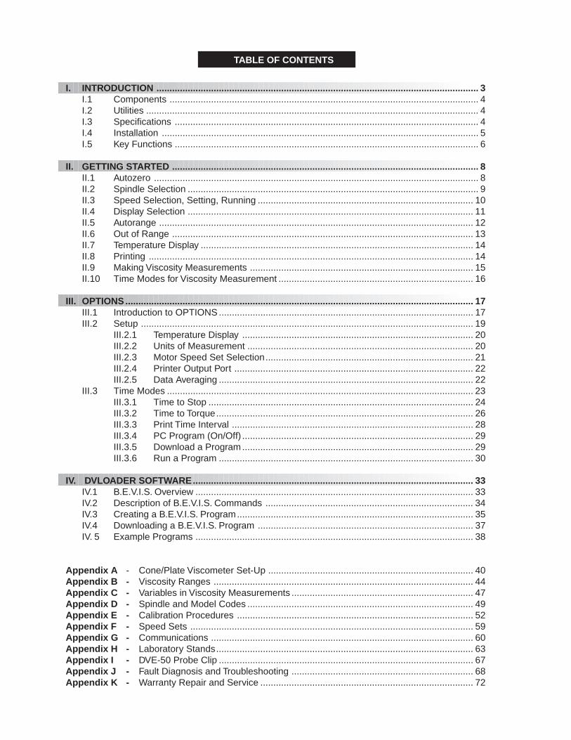
TABLE OF CONTENTS
I. INTRODUCTION ............................................................................................................................ 3I.1 Components ....................................................................................................................... 4I.2 Utilities ................................................................................................................................ 4I.3 Specifications ..................................................................................................................... 4I.4 Installation .......................................................................................................................... 5I.5 Key Functions ..................................................................................................................... 6
II. GETTING STARTED ...................................................................................................................... 8II.1 Autozero ............................................................................................................................. 8II.2 Spindle Selection ................................................................................................................ 9II.3 Speed Selection, Setting, Running ................................................................................... 10II.4 Display Selection .............................................................................................................. 11II.5 Autorange ......................................................................................................................... 12II.6 Out of Range .................................................................................................................... 13II.7 Temperature Display ......................................................................................................... 14II.8 Printing ............................................................................................................................. 14II.9 Making Viscosity Measurements ...................................................................................... 15II.10 Time Modes for Viscosity Measurement ........................................................................... 16
III. OPTIONS ...................................................................................................................................... 17III.1 Introduction to OPTIONS .................................................................................................. 17III.2 Setup ................................................................................................................................ 19
III.2.1 Temperature Display ......................................................................................... 20III.2.2 Units of Measurement ....................................................................................... 20III.2.3 Motor Speed Set Selection................................................................................ 21III.2.4 Printer Output Port ............................................................................................ 22III.2.5 Data Averaging .................................................................................................. 22
III.3 Time Modes ...................................................................................................................... 23III.3.1 Time to Stop ...................................................................................................... 24III.3.2 Time to Torque................................................................................................... 26III.3.3 Print Time Interval ............................................................................................. 28III.3.4 PC Program (On/Off) ......................................................................................... 29III.3.5 Download a Program......................................................................................... 29III.3.6 Run a Program .................................................................................................. 30
IV. DVLOADER SOFTWARE......................................................................................................... ... 33IV.1 B.E.V.I.S. Overview ........................................................................................................... 33IV.2 Description of B.E.V.I.S. Commands ................................................................................ 34IV.3 Creating a B.E.V.I.S. Program........................................................................................... 35IV.4 Downloading a B.E.V.I.S. Program ................................................................................... 37IV. 5 Example Programs ........................................................................................................... 38
Appendix A - Cone/Plate Viscometer Set-Up ............................................................................... 40 Appendix B - Viscosity Ranges .................................................................................................... 44 Appendix C - Variables in Viscosity Measurements ...................................................................... 47 Appendix D - Spindle and Model Codes ....................................................................................... 49 Appendix E - Calibration Procedures ........................................................................................... 52 Appendix F - Speed Sets ............................................................................................................. 59 Appendix G - Communications ..................................................................................................... 60 Appendix H - Laboratory Stands................................................................................................... 63 Appendix I - DVE-50 Probe Clip .................................................................................................. 67 Appendix J - Fault Diagnosis and Troubleshooting ...................................................................... 68 Appendix K - Warranty Repair and Service .................................................................................. 72
Brookfield Engineering Labs., Inc. Page 3 Manual No. M/97-164-D1000
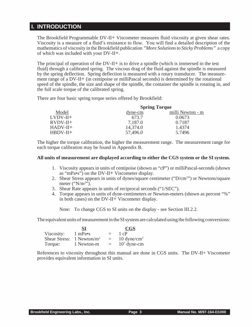
I. INTRODUCTION
The Brookfield Programmable DV-II + Viscometer measures fluid viscosity at given shear rates.Viscosity is a measure of a fluid’s resistance to flow. You will find a detailed description of themathematics of viscosity in the Brookfield publication ”More Solutions to Sticky Problems” a copyof which was included with your DV-II+.
The principal of operation of the DV-II+ is to drive a spindle (which is immersed in the testfluid) through a calibrated spring. The viscous drag of the fluid against the spindle is measuredby the spring deflection. Spring deflection is measured with a rotary transducer. The measure-ment range of a DV-II+ (in centipoise or milliPascal seconds) is determined by the rotationalspeed of the spindle, the size and shape of the spindle, the container the spindle is rotating in, andthe full scale torque of the calibrated spring.
There are four basic spring torque series offered by Brookfield:
Spring TorqueModel dyne-cm milli Newton - m
LVDV-II + 673.7 0.0673RVDV-II + 7,187.0 0.7187HADV-II + 14,374.0 1.4374HBDV-II + 57,496.0 5.7496
The higher the torque calibration, the higher the measurement range. The measurement range foreach torque calibration may be found in Appendix B.
All units of measurement are displayed according to either the CGS system or the SI system.
1. Viscosity appears in units of centipoise (shown as “cP”) or milliPascal-seconds (shownas “mPa•s”) on the DV-II+ Viscometer display.
2. Shear Stress appears in units of dynes/square centimeter (“D/cm2”) or Newtons/squaremeter (“N/m2”).
3. Shear Rate appears in units of reciprocal seconds (“1/SEC”).4. Torque appears in units of dyne-centimeters or Newton-meters (shown as percent “%”
in both cases) on the DV-II+ Viscometer display.
Note: To change CGS to SI units on the display - see Section III.2.2.
The equivalent units of measurement in the SI system are calculated using the following conversions:
SI CGSViscosity: 1 mPa•s = 1 cPShear Stress: 1 Newton/m2 = 10 dyne/cm2
Torque: 1 Newton-m = 107 dyne-cm
References to viscosity throughout this manual are done in CGS units. The DV-II+ Viscometerprovides equivalent information in SI units.
Brookfield Engineering Labs., Inc. Page 4 Manual No. M/97-164-D1000
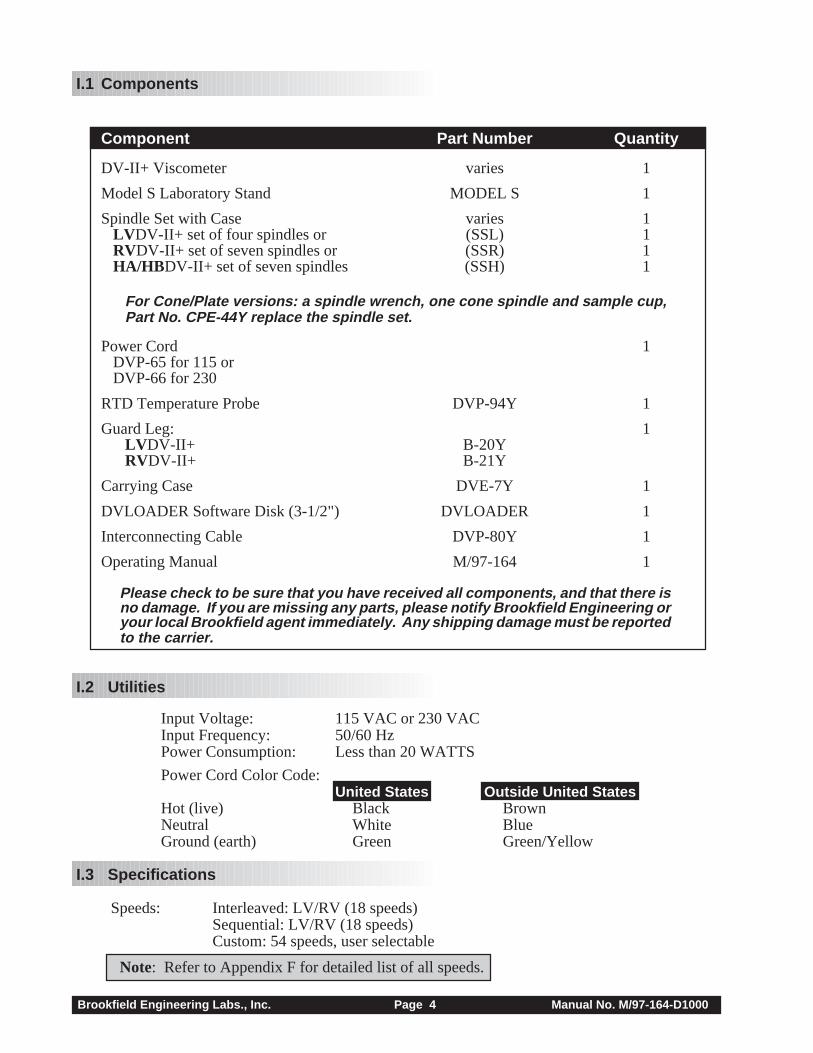
I.1 Components
Component Part Number Quantity
DV-II+ Viscometer varies 1
Model S Laboratory Stand MODEL S 1
Spindle Set with Case varies 1 LV DV-II+ set of four spindles or (SSL) 1 RVDV-II+ set of seven spindles or (SSR) 1 HA/HB DV-II+ set of seven spindles (SSH) 1
For Cone/Plate versions: a spindle wrench, one cone spindle and sample cup,Part No. CPE-44Y replace the spindle set.
Power Cord 1 DVP-65 for 115 or DVP-66 for 230
RTD Temperature Probe DVP-94Y 1
Guard Leg: 1LV DV-II+ B-20YRVDV-II+ B-21Y
Carrying Case DVE-7Y 1
DVLOADER Software Disk (3-1/2") DVLOADER 1
Interconnecting Cable DVP-80Y 1
Operating Manual M/97-164 1
Please check to be sure that you have received all components, and that there isno damage. If you are missing any parts, please notify Brookfield Engineering oryour local Brookfield agent immediately. Any shipping damage must be reportedto the carrier.
I.2 Utilities
Input Voltage: 115 VAC or 230 VACInput Frequency: 50/60 HzPower Consumption: Less than 20 WATTS
Power Cord Color Code:United States Outside United States
Hot (live) Black BrownNeutral White BlueGround (earth) Green Green/Yellow
I.3 Specifications
Speeds: Interleaved: LV/RV (18 speeds)Sequential: LV/RV (18 speeds)Custom: 54 speeds, user selectable
Note: Refer to Appendix F for detailed list of all speeds.
Brookfield Engineering Labs., Inc. Page 5 Manual No. M/97-164-D1000
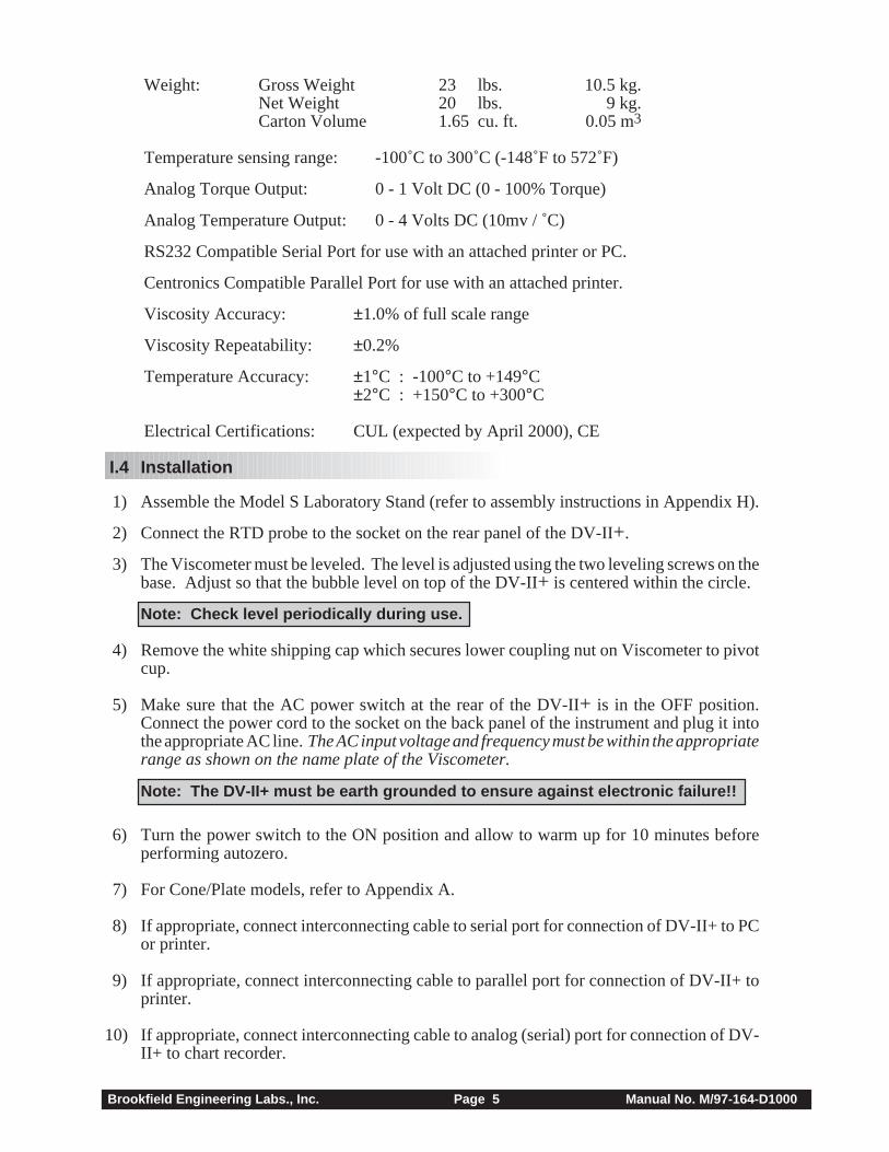
Weight: Gross Weight 23 lbs. 10.5 kg.Net Weight 20 lbs. 9 kg.Carton Volume 1.65 cu. ft. 0.05 m3
Temperature sensing range: -100˚C to 300˚C (-148˚F to 572˚F)
Analog Torque Output: 0 - 1 Volt DC (0 - 100% Torque)
Analog Temperature Output: 0 - 4 Volts DC (10mv / ˚C)
RS232 Compatible Serial Port for use with an attached printer or PC.
Centronics Compatible Parallel Port for use with an attached printer.
Viscosity Accuracy: ±1.0% of full scale range
Viscosity Repeatability: ±0.2%
Temperature Accuracy: ±1°C : -100°C to +149°C±2°C : +150°C to +300°C
Electrical Certifications: CUL (expected by April 2000), CE
I.4 Installation
1) Assemble the Model S Laboratory Stand (refer to assembly instructions in Appendix H).
2) Connect the RTD probe to the socket on the rear panel of the DV-II+.
3) The Viscometer must be leveled. The level is adjusted using the two leveling screws on thebase. Adjust so that the bubble level on top of the DV-II+ is centered within the circle.
Note: Check level periodically during use.
4) Remove the white shipping cap which secures lower coupling nut on Viscometer to pivotcup.
5) Make sure that the AC power switch at the rear of the DV-II+ is in the OFF position.Connect the power cord to the socket on the back panel of the instrument and plug it intothe appropriate AC line. The AC input voltage and frequency must be within the appropriaterange as shown on the name plate of the Viscometer.
Note: The DV-II+ must be earth grounded to ensure against electronic failure!!
6) Turn the power switch to the ON position and allow to warm up for 10 minutes beforeperforming autozero.
7) For Cone/Plate models, refer to Appendix A.
8) If appropriate, connect interconnecting cable to serial port for connection of DV-II+ to PCor printer.
9) If appropriate, connect interconnecting cable to parallel port for connection of DV-II+ toprinter.
10) If appropriate, connect interconnecting cable to analog (serial) port for connection of DV-II+ to chart recorder.
Brookfield Engineering Labs., Inc. Page 6 Manual No. M/97-164-D1000
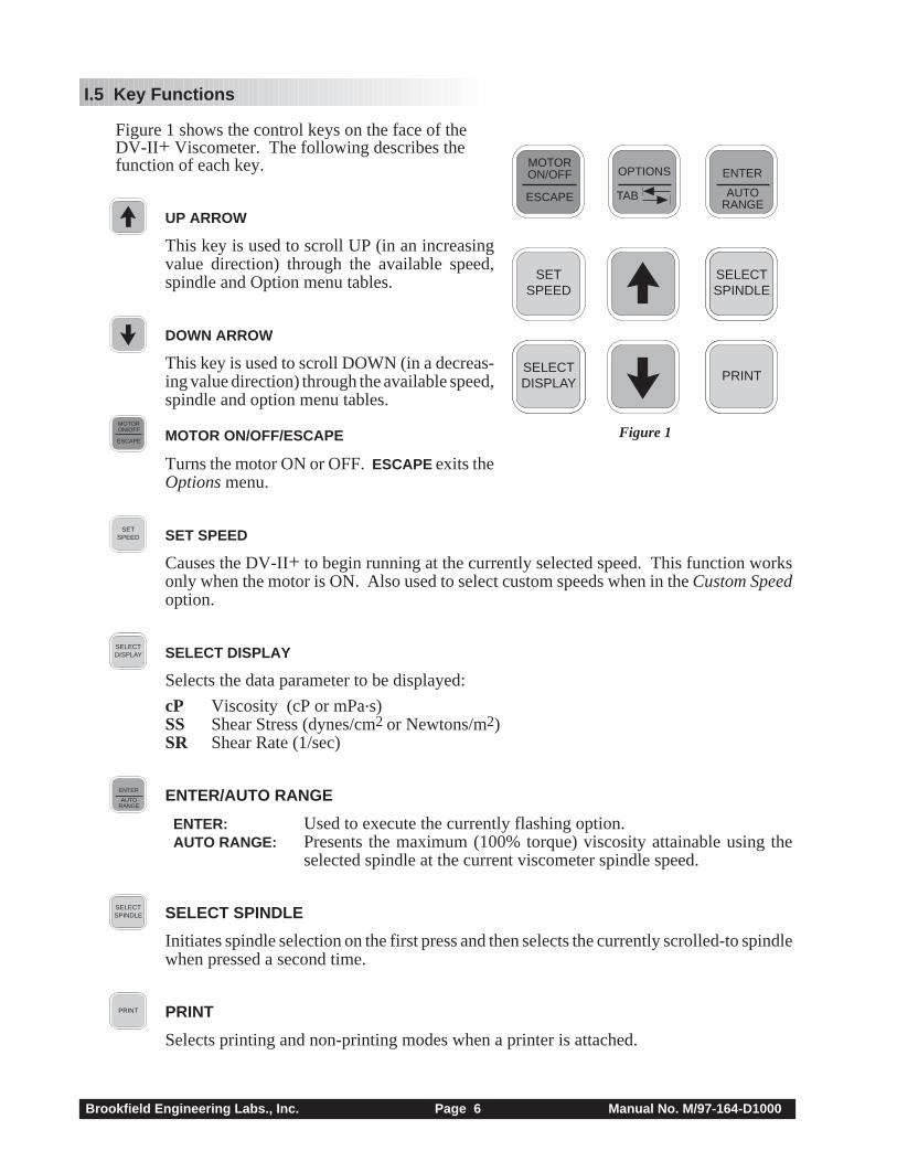
I.5 Key Functions
Figure 1 shows the control keys on the face of theDV-II + Viscometer. The following describes thefunction of each key.
UP ARROW
This key is used to scroll UP (in an increasingvalue direction) through the available speed,spindle and Option menu tables.
DOWN ARROW
This key is used to scroll DOWN (in a decreas-ing value direction) through the available speed,spindle and option menu tables.
MOTORON/OFF
ESCAPE MOTOR ON/OFF/ESCAPE
Turns the motor ON or OFF. ESCAPE exits theOptions menu.
SETSPEED SET SPEED
Causes the DV-II+ to begin running at the currently selected speed. This function worksonly when the motor is ON. Also used to select custom speeds when in the Custom Speedoption.
SELECTDISPLAY SELECT DISPLAY
Selects the data parameter to be displayed:
cP Viscosity (cP or mPa.s)SS Shear Stress (dynes/cm2 or Newtons/m2)SR Shear Rate (1/sec)
AUTORANGE
ENTER ENTER/AUTO RANGE
ENTER: Used to execute the currently flashing option. AUTO RANGE: Presents the maximum (100% torque) viscosity attainable using the
selected spindle at the current viscometer spindle speed.
SELECTSPINDLESELECTSPINDLE SELECT SPINDLE
Initiates spindle selection on the first press and then selects the currently scrolled-to spindlewhen pressed a second time.
PRINT PRINT
Selects printing and non-printing modes when a printer is attached.
Figure 1
SETSPEED
SELECTSPINDLESELECTSPINDLE
PRINTSELECTDISPLAY
MOTORON/OFF
ESCAPE AUTORANGE
ENTER
TAB
OPTIONS
Brookfield Engineering Labs., Inc. Page 7 Manual No. M/97-164-D1000
TAB
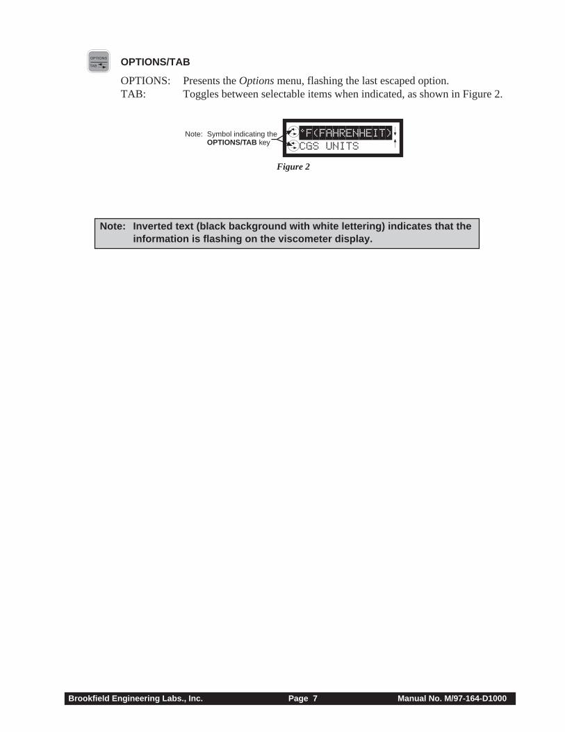
OPTIONS OPTIONS/TAB
OPTIONS: Presents the Options menu, flashing the last escaped option.TAB: Toggles between selectable items when indicated, as shown in Figure 2.
L°F(FAHRENHEIT) CGS UNITS
Note: Symbol indicating theOPTIONS/TAB key
Figure 2
Note: Inverted text (black background with white lettering) indicates that theinformation is flashing on the viscometer display.
Brookfield Engineering Labs., Inc. Page 8 Manual No. M/97-164-D1000
II. GETTING STARTED
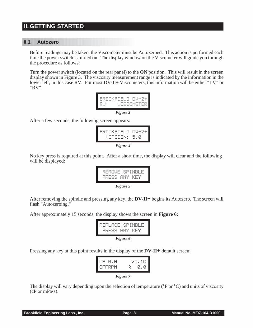
II.1 Autozero
Before readings may be taken, the Viscometer must be Autozeroed. This action is performed eachtime the power switch is turned on. The display window on the Viscometer will guide you throughthe procedure as follows:
Turn the power switch (located on the rear panel) to the ON position. This will result in the screendisplay shown in Figure 3. The viscosity measurement range is indicated by the information in thelower left, in this case RV. For most DV-II+ Viscometers, this information will be either “LV” or“RV”.
BROOKFIELD DV-2+RV VISCOMETER
Figure 3
After a few seconds, the following screen appears:
BROOKFIELD DV-2+ VERSION: 5.0
Figure 4
No key press is required at this point. After a short time, the display will clear and the followingwill be displayed:
REMOVE SPINDLE PRESS ANY KEY
Figure 5
After removing the spindle and pressing any key, the DV-II + begins its Autozero. The screen willflash "Autozeroing."
After approximately 15 seconds, the display shows the screen in Figure 6:
REPLACE SPINDLE PRESS ANY KEY
Figure 6
Pressing any key at this point results in the display of the DV-II + default screen:
CP 0.0 20.1COFFRPM % 0.0
Figure 7
The display will vary depending upon the selection of temperature (°F or °C) and units of viscosity(cP or mPa•s).
Brookfield Engineering Labs., Inc. Page 9 Manual No. M/97-164-D1000
II.2 SELECTSPINDLESELECTSPINDLE Spindle Selection
LVDV-II+ Viscometers are provided with a set of four spindles and a narrow guardleg; RVDV-II+Viscometers come with a set of seven spindles and a wider guardleg; HADV-II+ and HBDV-II+Viscometers come with a set of seven spindles and no guardleg. (See Appendix E for moreinformation on the guardleg.)
The spindles are attached to the viscometer by screwing them onto the lower shaft. Note that thespindles have a left-hand thread. The lower shaft should be secured and slightly lifted with one handwhile screwing the spindle to the left. The face of the spindle nut and the matching surface on thelower shaft should be smooth and clean to prevent eccentric rotation of the spindle. Spindles can beidentified by the number on the side of the spindle coupling nut.
The DV-II+ must have a Spindle Entry Code number to calculate Viscosity, Shear Rate and ShearStress values. The DV-II+ memory contains parameters for all standard Brookfield spindlesincluding custom spindles and the two digit entry code for each spindle (the complete list of entrycodes may be found in Appendix D).
Note: The DV-II+ will remember the Spindle Entry Code which was in use when thepower was turned off.
Pressing the SELECT SPINDLE key will display the current selected spindle code instead oftemperature and cause the character S to begin to blink . It will blink for about three seconds. If theUP or DOWN ARROW keys are pressed (while S is blinking) the two character spindle value to the rightof the S character will begin to change (in either an increasing or decreasing direction depending uponwhich ARROW key is pressed) for each press of the key. If the ARROW key is pressed and held, thedisplay will scroll through the spindle codes for as long as the ARROW key is depressed. When itreaches the last item in the list (either at the top or bottom of the list) the spindle code displayed will“roll-over” to either the first or last spindle code and the scroll action will continue.
When the desired spindle code is displayed, release the ARROW key to halt further scrolling. Pressthe SELECT SPINDLE key once again. This will cause the S character to cease blinking and the newspindle code will be accepted for use in viscometer calculations.
Note: You have approximately three seconds in which to press the SELECT SPINDLEkey before the blinking stops. If you fail to press the SELECT SPINDLE keybefore the blinking stops you will have to repeat the above steps and re-selectthe desired spindle.
The DV-II+ will begin to calculate using the new spindle parameters as soon as the SELECT SPINDLEkey is pressed the second time.
Note: The number 99 spindle is for use with special spindles when using Brook-field’s WINGATHER computer program. Refer to the WINGATHER operatormanual for further information on using “ 99” spindles.
The DV-II+ may also be programmed at Brookfield Engineering for “special” user spindles. These“special” spindles will appear on the spindle scroll list starting with designation “AA ” and continuingthrough “AZ ”. Contact Brookfield Engineering regarding your needs for special spindles.
Brookfield Engineering Labs., Inc. Page 10 Manual No. M/97-164-D1000
II.3 SETSPEED Speed Selection, Setting, Running
There are 54 speeds programmed into the DV-II+. These speeds correspond to the standard LVT,RVT, HAT, HBT, LVF and RVF dial models (18 possible speeds altogether) plus 36 additionalspeeds.
The DV-II+ comes with the Sequential Speed Set already selected (see Appendix F). The speed setwill start at speed 0.0. It will then scroll up through the LV speeds, pass through speed 0.0 again, andthen scroll up through the RV speeds, pass through speed 0.0 again and then repeat the abovesequence.
The DV-II+ can also be configured by the operator to interleave the LV and RV speeds. See SectionIII.2.3 on Setup for a description of how to install the Interleave Speed Set.
A complete list of speed sets and custom speeds is included in Appendix F. The DV-II+ can beprogrammed to select up to 19 of the 54 speeds for use at any one time. Speed 0.0 is the 20th speedand is automatically included. See Section III. 2.3.2 on Setup for a description of how to install aCustom Speed Set.
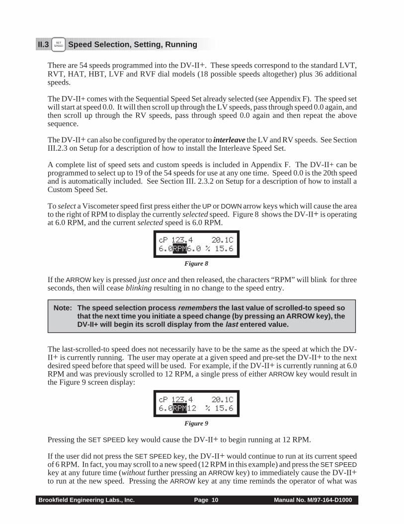
To select a Viscometer speed first press either the UP or DOWN arrow keys which will cause the areato the right of RPM to display the currently selected speed. Figure 8 shows the DV-II+ is operatingat 6.0 RPM, and the current selected speed is 6.0 RPM.
cP 123.4 20.1C6.0RPM6.0 % 15.6
Figure 8
If the ARROW key is pressed just once and then released, the characters “RPM” will blink for threeseconds, then will cease blinking resulting in no change to the speed entry.
Note: The speed selection process remembers the last value of scrolled-to speed sothat the next time you initiate a speed change (by pressing an ARROW key), theDV-II+ will begin its scroll display from the last entered value.
The last-scrolled-to speed does not necessarily have to be the same as the speed at which the DV-II+ is currently running. The user may operate at a given speed and pre-set the DV-II+ to the nextdesired speed before that speed will be used. For example, if the DV-II+ is currently running at 6.0RPM and was previously scrolled to 12 RPM, a single press of either ARROW key would result inthe Figure 9 screen display:
cP 123.4 20.1C6.0RPM12 % 15.6
Figure 9
Pressing the SET SPEED key would cause the DV-II+ to begin running at 12 RPM.
If the user did not press the SET SPEED key, the DV-II+ would continue to run at its current speedof 6 RPM. In fact, you may scroll to a new speed (12 RPM in this example) and press the SET SPEEDkey at any future time (without further pressing an ARROW key) to immediately cause the DV-II+to run at the new speed. Pressing the ARROW key at any time reminds the operator of what was
Brookfield Engineering Labs., Inc. Page 11 Manual No. M/97-164-D1000
selected for the next speed.
If an ARROW key is pressed and held the DV-II+ will scroll up (or down) through the speed table.When it reaches the last speed in the list (either at the top or bottom of the list) the speed displayedwill “roll-over” to either the first or last speed in the table and the scroll action will continue.
When the required speed is displayed, release the ARROW key to halt further scrolling. You haveapproximately two seconds (before the blinking RPM stops) in which to press the SET SPEED keyto immediately begin rotation at the new speed.
Pressing the MOTOR ON/OFF/ESCAPE key stops the Viscometer spindle rotation. Pressing this keysets the DV-II+ to 0.0 RPM and causes the screen display to change as shown in Figure 10:
cP 0.0 20.1COFFRPM % 0.0
Figure 10
Pressing the MOTOR ON/OFF/ESCAPE key again immediately starts the DV-II+ running at the lastscrolled-to-speed. If you had been running at 12 RPM, pressed MOTOR ON/OFF/ESCAPE and thenre-started the DV-II+ by pressing MOTOR ON/OFF/ESCAPE once again, you would again be runningat 12 RPM. However, if while the motor was off you had scrolled to a new speed of 0.5 RPM, pressingthe MOTOR ON/OFF/ESCAPE key would start the DV-II+ running at 0.5 RPM.
Note: During both spindle or speed selection and scrolling operations, the DV-II+ willcontinue to calculate and display Viscometer data as selected.
II.4 SELECTDISPLAY Display Selection
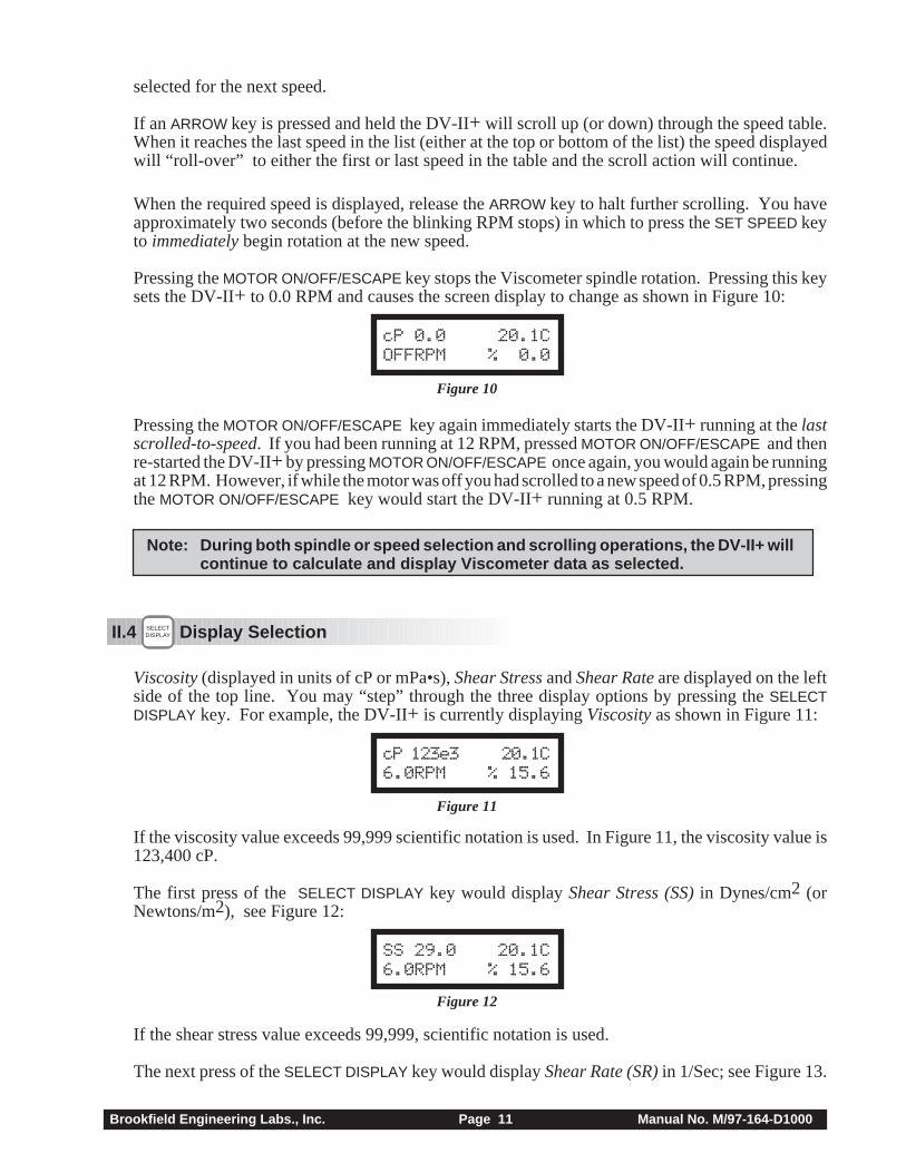
Viscosity (displayed in units of cP or mPa•s), Shear Stress and Shear Rate are displayed on the leftside of the top line. You may “step” through the three display options by pressing the SELECTDISPLAY key. For example, the DV-II+ is currently displaying Viscosity as shown in Figure 11:
cP 123e3 20.1C6.0RPM % 15.6
Figure 11
If the viscosity value exceeds 99,999 scientific notation is used. In Figure 11, the viscosity value is123,400 cP.
The first press of the SELECT DISPLAY key would display Shear Stress (SS) in Dynes/cm2 (orNewtons/m2), see Figure 12:
SS 29.0 20.1C6.0RPM % 15.6
Figure 12
If the shear stress value exceeds 99,999, scientific notation is used.
The next press of the SELECT DISPLAY key would display Shear Rate (SR) in 1/Sec; see Figure 13.
Brookfield Engineering Labs., Inc. Page 12 Manual No. M/97-164-D1000
SR 40.0 20.1C6.0RPM % 15.6
Figure 13
One more press of the SELECT DISPLAY key would result in a return to the viscosity screen, as shownin Figure 11.
Notes: 1. You may step through the display at any time. This will not interrupt anyViscometer calculations that are in progress.
2. Display of shear rate and shear stress requires selection of appropriatespindles. Otherwise, values displayed will be zero (0).
Units of Measurement
The DV-II+ Viscometer can be configured using the SETUP option (Section III.2.2) to display/print in either the CGS or SI system of units.
II.5 AUTORANGE
ENTER Autorange
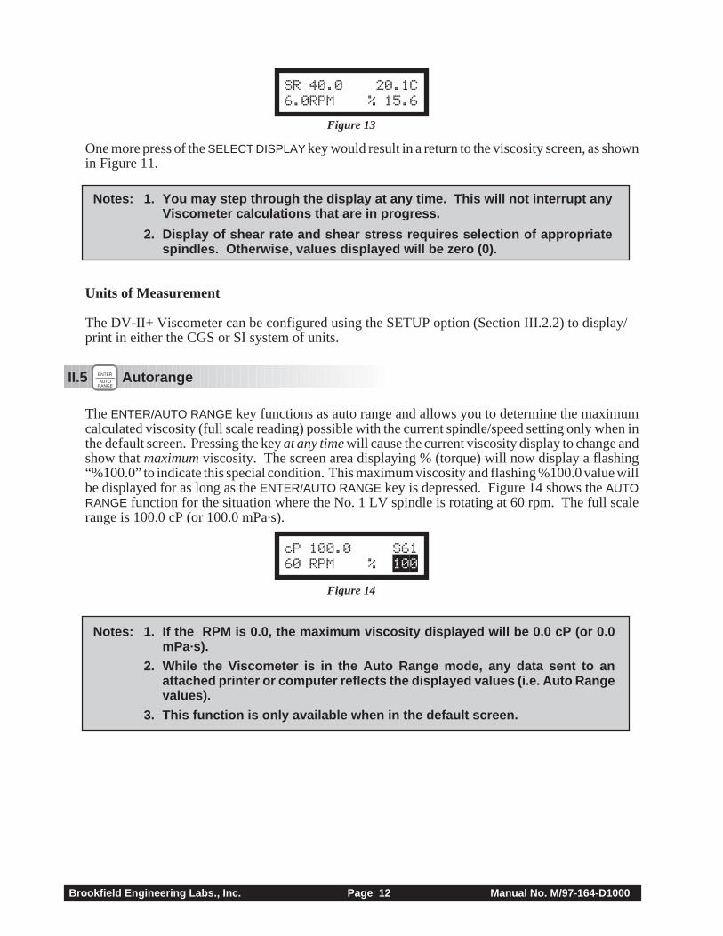
The ENTER/AUTO RANGE key functions as auto range and allows you to determine the maximumcalculated viscosity (full scale reading) possible with the current spindle/speed setting only when inthe default screen. Pressing the key at any time will cause the current viscosity display to change andshow that maximum viscosity. The screen area displaying % (torque) will now display a flashing“%100.0” to indicate this special condition. This maximum viscosity and flashing %100.0 value willbe displayed for as long as the ENTER/AUTO RANGE key is depressed. Figure 14 shows the AUTORANGE function for the situation where the No. 1 LV spindle is rotating at 60 rpm. The full scalerange is 100.0 cP (or 100.0 mPa.s).
cP 100.0 S6160 RPM % 100
Figure 14
Notes: 1. If the RPM is 0.0, the maximum viscosity displayed will be 0.0 cP (or 0.0mPa.s).
2. While the Viscometer is in the Auto Range mode, any data sent to anattached printer or computer reflects the displayed values (i.e. Auto Rangevalues).
3. This function is only available when in the default screen.
Brookfield Engineering Labs., Inc. Page 13 Manual No. M/97-164-D1000
II.6 Out of Range
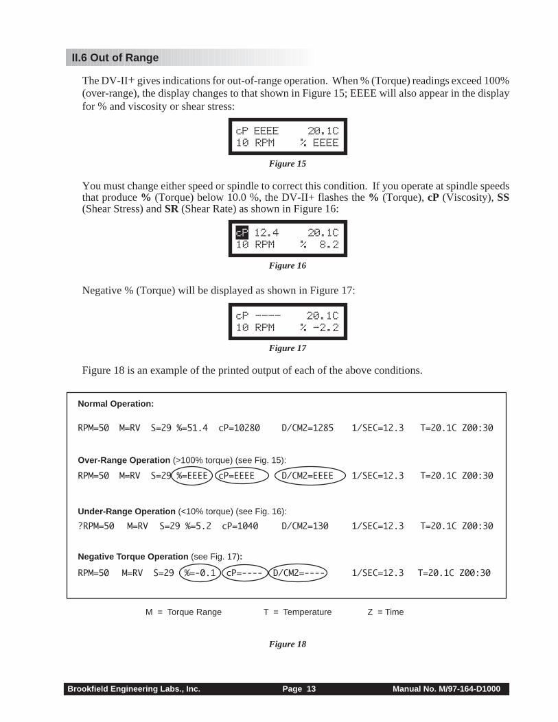
The DV-II+ gives indications for out-of-range operation. When % (Torque) readings exceed 100%(over-range), the display changes to that shown in Figure 15; EEEE will also appear in the displayfor % and viscosity or shear stress:
cP EEEE 20.1C10 RPM % EEEE
Figure 15
You must change either speed or spindle to correct this condition. If you operate at spindle speedsthat produce % (Torque) below 10.0 %, the DV-II+ flashes the % (Torque), cP (Viscosity), SS(Shear Stress) and SR (Shear Rate) as shown in Figure 16:
cP 12.4 20.1C10 RPM % 8.2
Figure 16
Negative % (Torque) will be displayed as shown in Figure 17:
cP ---- 20.1C10 RPM % -2.2
Figure 17
Figure 18 is an example of the printed output of each of the above conditions.
Figure 18
Normal Operation:
RPM=50 M=RV S=29 %=51.4 cP=10280 D/CM2=1285 1/SEC=12.3 T=20.1C Z00:30
Over-Range Operation (>100% torque) (see Fig. 15):
RPM=50 M=RV S=29 %=EEEE cP=EEEE D/CM2=EEEE 1/SEC=12.3 T=20.1C Z00:30
Under-Range Operation (<10% torque) (see Fig. 16):
?RPM=50 M=RV S=29 %=5.2 cP=1040 D/CM2=130 1/SEC=12.3 T=20.1C Z00:30
Negative Torque Operation (see Fig. 17):
RPM=50 M=RV S=29 %=-0.1 cP=---- D/CM2=---- 1/SEC=12.3 T=20.1C Z00:30
M = Torque Range T = Temperature Z = Time

Brookfield Engineering Labs., Inc. Page 14 Manual No. M/97-164-D1000
II.7 Temperature Display
The DV-II+ displays the temperature measured by its RTD temperature probe. Temperature may bedisplayed in either ˚C (Centigrade) or ̊F (Fahrenheit) units, depending upon selection from theOptions menu. As received, the default temperature display will be in ˚C (Centigrade) units as shownin the Figure 19:
cP 123.4 20.1C10 RPM % 19.7
Figure 19
If you turn on the DV-II+ with the temperature probe disconnected, or remove the temperature probeat any point after power-up, the display will indicate “- - - -C” . The four “dashes” indicate the absenceof the probe. If you were displaying temperature in Fahrenheit units the C would be replaced by anF. Accuracy of temperature measurement for the DV-II+ is shown in Table 1.
Table 1
Temperature Accuracies forProgrammable DV-II+ Viscometer
Temperature Range Temperature Accuracy
-100°C to +149°C ±1.0°C+150°C to +300°C ±2.0°C
II.8 PRINT Printing
The DV-II+ will print data to an attached Serial (RS232) or Parallel (centronics) printer. The printermust be attached to the appropriate rear panel output connector. See Appendix G for configurationand connection requirements.
Data may be printed in two ways:
1. Pressing the PRINT key once (for less than three (3) seconds) will result in the printing of onestandard print line.
2. If the PRINT key is pressed and held for more than three (3) seconds, the DV-II+ will then begincontinuous printer output at a print rate interval selected via the Options menu (see Section III.4).The display will show a flashing P in front of the % sign. See Figure 20.
cP 123.4 20.1C10 RPM P% 19.7
Figure 20
To stop continuous printing, press the PRINT key for one (1) second. The flashing P willdisappear on the viscometer display.
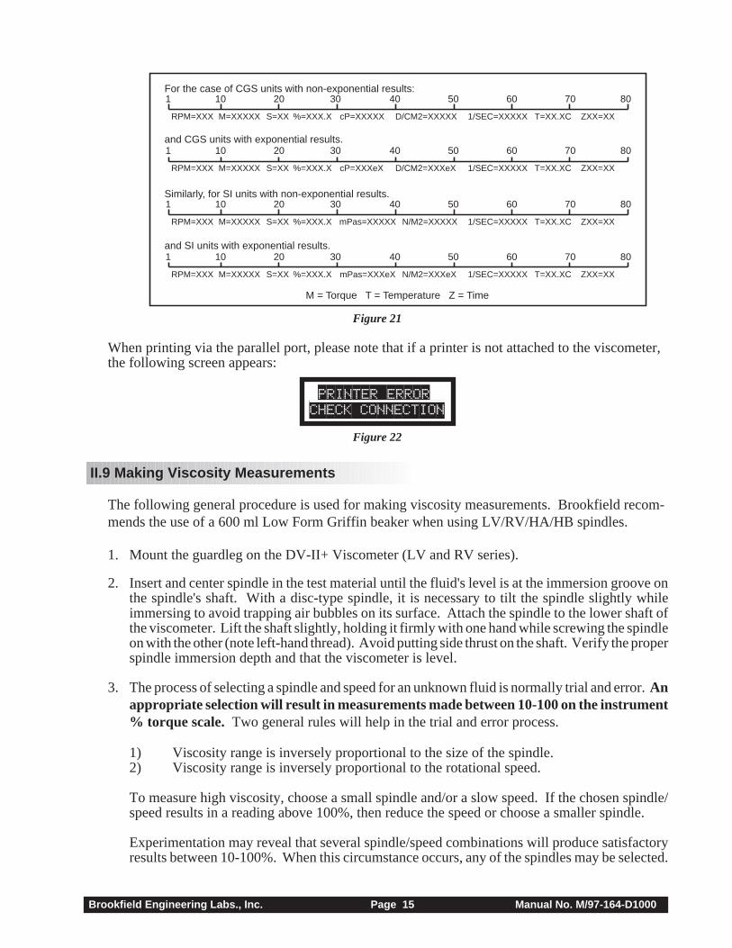
Figure 21 is an example of the print strings for CGS and SI units.
Brookfield Engineering Labs., Inc. Page 15 Manual No. M/97-164-D1000
Figure 21
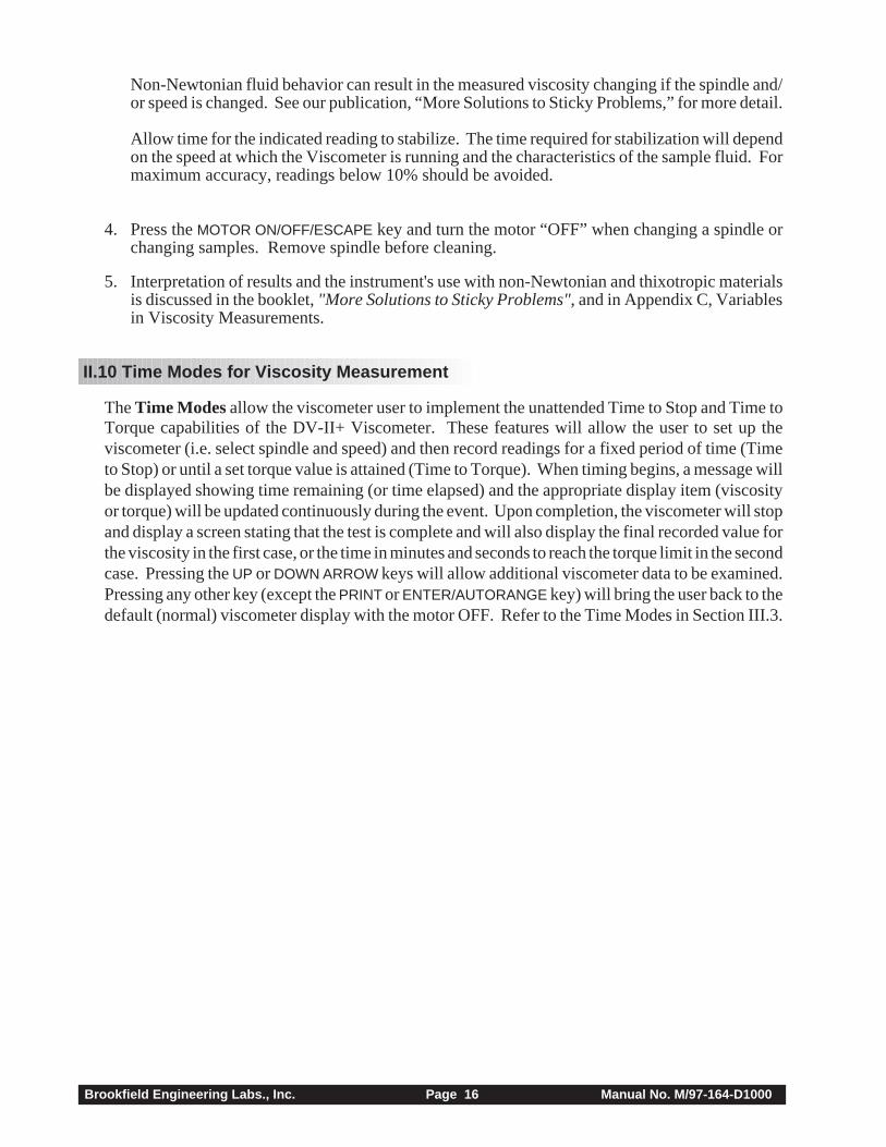
When printing via the parallel port, please note that if a printer is not attached to the viscometer,the following screen appears:
PRINTER ERRORCHECK CONNECTION
Figure 22
II.9 Making Viscosity Measurements
The following general procedure is used for making viscosity measurements. Brookfield recom-mends the use of a 600 ml Low Form Griffin beaker when using LV/RV/HA/HB spindles.
1. Mount the guardleg on the DV-II+ Viscometer (LV and RV series).
2. Insert and center spindle in the test material until the fluid's level is at the immersion groove onthe spindle's shaft. With a disc-type spindle, it is necessary to tilt the spindle slightly whileimmersing to avoid trapping air bubbles on its surface. Attach the spindle to the lower shaft ofthe viscometer. Lift the shaft slightly, holding it firmly with one hand while screwing the spindleon with the other (note left-hand thread). Avoid putting side thrust on the shaft. Verify the properspindle immersion depth and that the viscometer is level.
3. The process of selecting a spindle and speed for an unknown fluid is normally trial and error. Anappropriate selection will result in measurements made between 10-100 on the instrument% torque scale. Two general rules will help in the trial and error process.
1) Viscosity range is inversely proportional to the size of the spindle.2) Viscosity range is inversely proportional to the rotational speed.
To measure high viscosity, choose a small spindle and/or a slow speed. If the chosen spindle/speed results in a reading above 100%, then reduce the speed or choose a smaller spindle.
Experimentation may reveal that several spindle/speed combinations will produce satisfactoryresults between 10-100%. When this circumstance occurs, any of the spindles may be selected.
For the case of CGS units with non-exponential results:
and CGS units with exponential results.
Similarly, for SI units with non-exponential results.
and SI units with exponential results.
M = Torque T = Temperature Z = Time
1 10 20 30 40 50 60 70 80
RPM=XXX M=XXXXX S=XX %=XXX.X cP=XXXXX D/CM2=XXXXX 1/SEC=XXXXX T=XX.XC ZXX=XX
RPM=XXX M=XXXXX S=XX %=XXX.X cP=XXXeX D/CM2=XXXeX 1/SEC=XXXXX T=XX.XC ZXX=XX
1 10 20 30 40 50 60 70 80
RPM=XXX M=XXXXX S=XX %=XXX.X mPas=XXXXX N/M2=XXXXX 1/SEC=XXXXX T=XX.XC ZXX=XX
1 10 20 30 40 50 60 70 80
1 10 20 30 40 50 60 70 80
RPM=XXX M=XXXXX S=XX %=XXX.X mPas=XXXeX N/M2=XXXeX 1/SEC=XXXXX T=XX.XC ZXX=XX
Brookfield Engineering Labs., Inc. Page 16 Manual No. M/97-164-D1000
Non-Newtonian fluid behavior can result in the measured viscosity changing if the spindle and/or speed is changed. See our publication, “More Solutions to Sticky Problems,” for more detail.
Allow time for the indicated reading to stabilize. The time required for stabilization will dependon the speed at which the Viscometer is running and the characteristics of the sample fluid. Formaximum accuracy, readings below 10% should be avoided.
4. Press the MOTOR ON/OFF/ESCAPE key and turn the motor “OFF” when changing a spindle orchanging samples. Remove spindle before cleaning.
5. Interpretation of results and the instrument's use with non-Newtonian and thixotropic materialsis discussed in the booklet, "More Solutions to Sticky Problems", and in Appendix C, Variablesin Viscosity Measurements.
II.10 Time Modes for Viscosity Measurement
The Time Modes allow the viscometer user to implement the unattended Time to Stop and Time toTorque capabilities of the DV-II+ Viscometer. These features will allow the user to set up theviscometer (i.e. select spindle and speed) and then record readings for a fixed period of time (Timeto Stop) or until a set torque value is attained (Time to Torque). When timing begins, a message willbe displayed showing time remaining (or time elapsed) and the appropriate display item (viscosityor torque) will be updated continuously during the event. Upon completion, the viscometer will stopand display a screen stating that the test is complete and will also display the final recorded value forthe viscosity in the first case, or the time in minutes and seconds to reach the torque limit in the secondcase. Pressing the UP or DOWN ARROW keys will allow additional viscometer data to be examined.Pressing any other key (except the PRINT or ENTER/AUTORANGE key) will bring the user back to thedefault (normal) viscometer display with the motor OFF. Refer to the Time Modes in Section III.3.
Brookfield Engineering Labs., Inc. Page 17 Manual No. M/97-164-D1000
III. OPTIONS
III.1 TAB
OPTIONS Introduction to OPTIONS
The OPTIONS/TAB key provides access to the configuration (Setup) of the DV-II+ Viscometer aswell as special functions that can enhance the user's ability to make viscosity measurements.
The Options menu, shown in Table 1, gives a complete picture of the various configurationchoices and special functions.
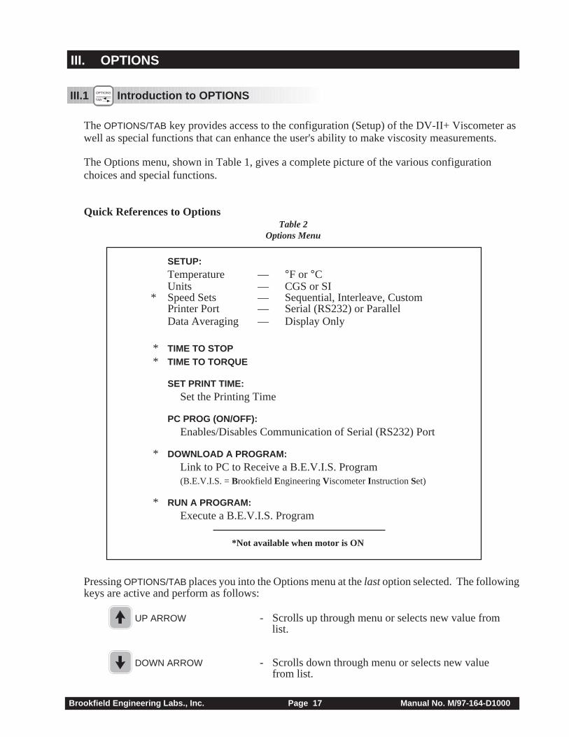
Quick References to OptionsTable 2
Options Menu
SETUP:Temperature — °F or °CUnits — CGS or SI
* Speed Sets — Sequential, Interleave, CustomPrinter Port — Serial (RS232) or ParallelData Averaging — Display Only
* TIME TO STOP* TIME TO TORQUE
SET PRINT TIME:Set the Printing Time
PC PROG (ON/OFF):Enables/Disables Communication of Serial (RS232) Port
* DOWNLOAD A PROGRAM:Link to PC to Receive a B.E.V.I.S. Program(B.E.V.I.S. = Brookfield Engineering Viscometer Instruction Set)
* RUN A PROGRAM:Execute a B.E.V.I.S. Program
*Not available when motor is ON
Pressing OPTIONS/TAB places you into the Options menu at the last option selected. The followingkeys are active and perform as follows:
UP ARROW - Scrolls up through menu or selects new value fromlist.
DOWN ARROW - Scrolls down through menu or selects new valuefrom list.
Brookfield Engineering Labs., Inc. Page 18 Manual No. M/97-164-D1000
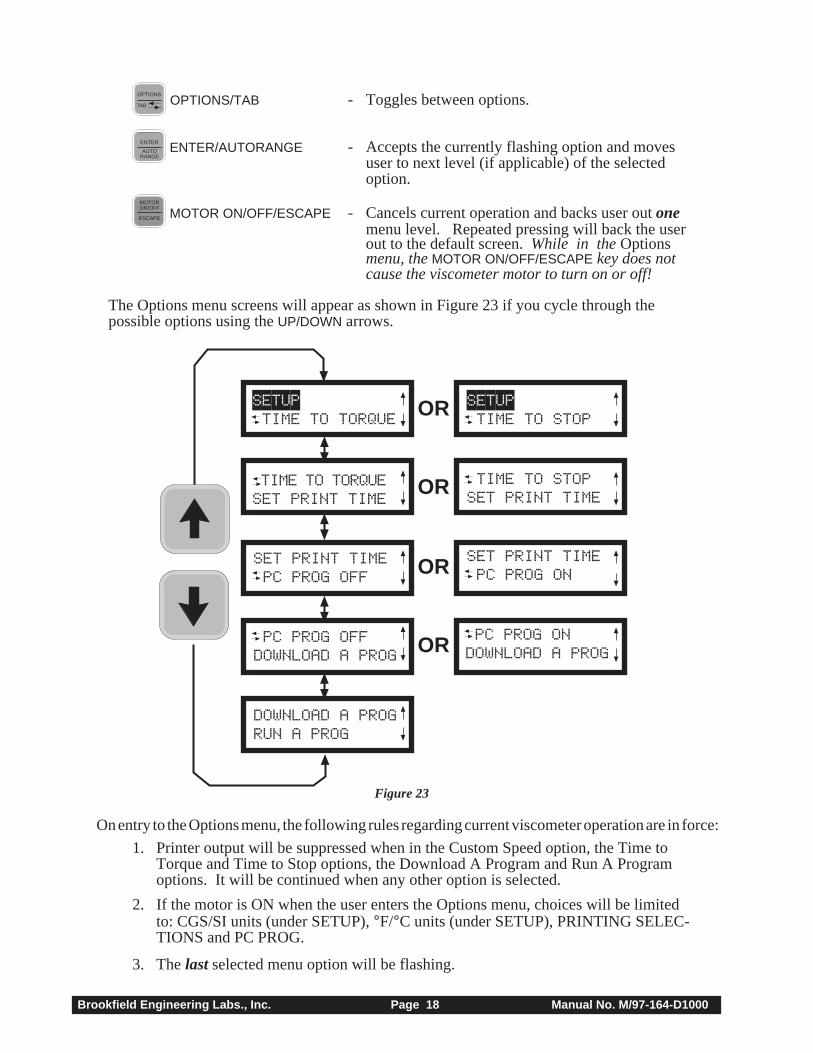
TAB
OPTIONS OPTIONS/TAB - Toggles between options.
AUTORANGE
ENTER ENTER/AUTORANGE - Accepts the currently flashing option and movesuser to next level (if applicable) of the selectedoption.
MOTORON/OFF
ESCAPE MOTOR ON/OFF/ESCAPE - Cancels current operation and backs user out onemenu level. Repeated pressing will back the userout to the default screen. While in the Optionsmenu, the MOTOR ON/OFF/ESCAPE key does notcause the viscometer motor to turn on or off!
The Options menu screens will appear as shown in Figure 23 if you cycle through thepossible options using the UP/DOWN arrows.
TIME TO TORQUESET PRINT TIME
PC PROG OFFDOWNLOAD A PROG
DOWNLOAD A PROGRUN A PROG
SETUP TIME TO TORQUE
SET PRINT TIME PC PROG OFF
SETUP TIME TO STOP
LTIME TO STOPSET PRINT TIME
SET PRINT TIME PC PROG ON
LPC PROG ONDOWNLOAD A PROG
OR
OR
OR
OR
Figure 23
On entry to the Options menu, the following rules regarding current viscometer operation are in force:
1. Printer output will be suppressed when in the Custom Speed option, the Time toTorque and Time to Stop options, the Download A Program and Run A Programoptions. It will be continued when any other option is selected.
2. If the motor is ON when the user enters the Options menu, choices will be limitedto: CGS/SI units (under SETUP), °F/°C units (under SETUP), PRINTING SELEC-TIONS and PC PROG.
3. The last selected menu option will be flashing.
Brookfield Engineering Labs., Inc. Page 19 Manual No. M/97-164-D1000
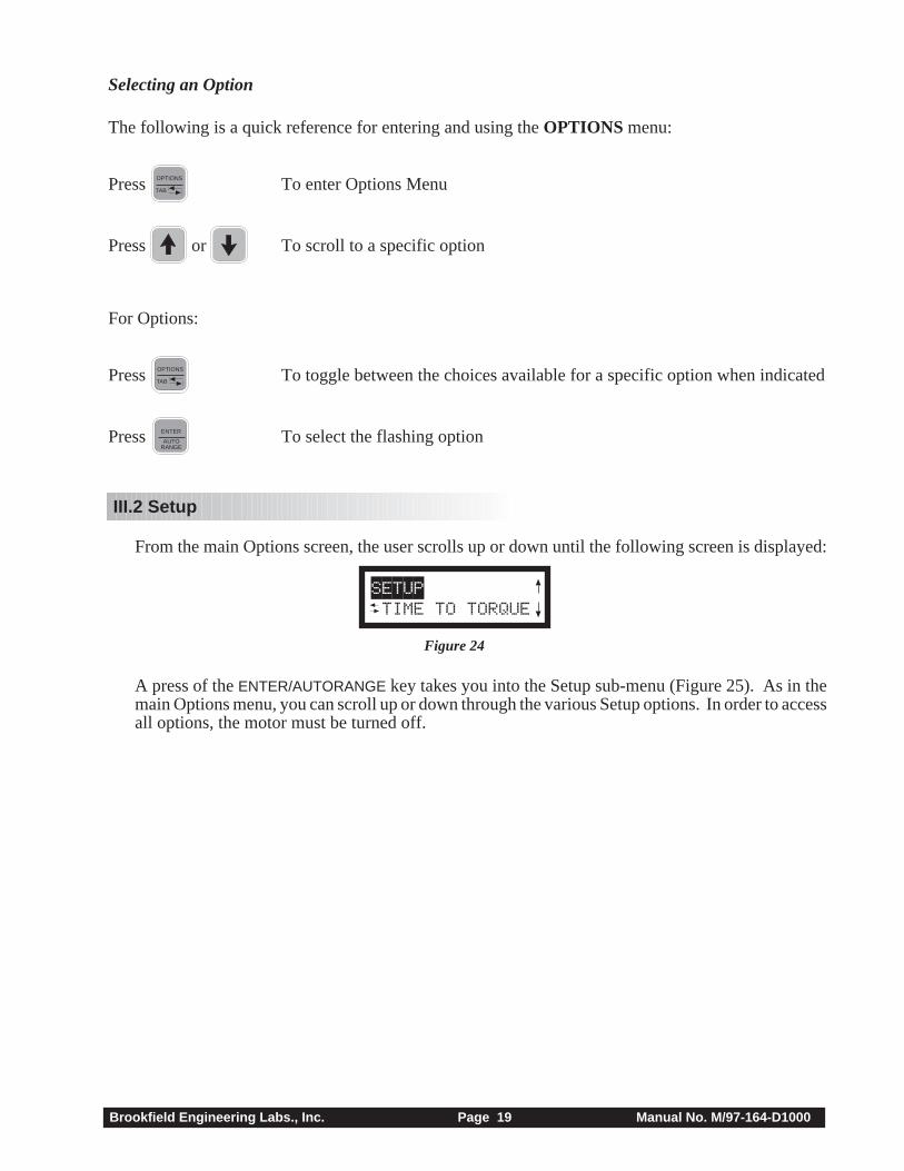
Selecting an Option
The following is a quick reference for entering and using the OPTIONS menu:
Press TAB
OPTIONS To enter Options Menu
Press or To scroll to a specific option
For Options:
Press TAB
OPTIONS To toggle between the choices available for a specific option when indicated
Press AUTORANGE
ENTER To select the flashing option
III.2 Setup
From the main Options screen, the user scrolls up or down until the following screen is displayed:
SETUP TIME TO TORQUE
Figure 24
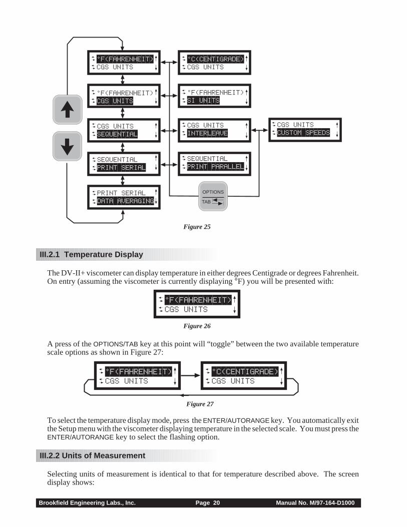
A press of the ENTER/AUTORANGE key takes you into the Setup sub-menu (Figure 25). As in themain Options menu, you can scroll up or down through the various Setup options. In order to accessall options, the motor must be turned off.
Brookfield Engineering Labs., Inc. Page 20 Manual No. M/97-164-D1000
L°F(FAHRENHEIT) CGS UNITS
LSEQUENTIAL PRINT SERIAL
LPRINT SERIAL DATA AVERAGING
L°F(FAHRENHEIT) CGS UNITS
LCGS UNITS SEQUENTIAL
L°C(CENTIGRADE) CGS UNITS
L°F(FAHRENHEIT) SI UNITS
LCGS UNITS INTERLEAVE
LSEQUENTIAL PRINT PARALLEL
LCGS UNITS CUSTOM SPEEDS
TAB
OPTIONS
Figure 25
III.2.1 Temperature Display
The DV-II+ viscometer can display temperature in either degrees Centigrade or degrees Fahrenheit.On entry (assuming the viscometer is currently displaying °F) you will be presented with:
L°F(FAHRENHEIT) CGS UNITS
Figure 26
A press of the OPTIONS/TAB key at this point will “toggle” between the two available temperaturescale options as shown in Figure 27:
L°F(FAHRENHEIT) CGS UNITS
L°C(CENTIGRADE) CGS UNITS
Figure 27
To select the temperature display mode, press the ENTER/AUTORANGE key. You automatically exitthe Setup menu with the viscometer displaying temperature in the selected scale. You must press theENTER/AUTORANGE key to select the flashing option.
III.2.2 Units of Measurement
Selecting units of measurement is identical to that for temperature described above. The screendisplay shows:
Brookfield Engineering Labs., Inc. Page 21 Manual No. M/97-164-D1000
L°F(FAHRENHEIT) CGS UNITS
Figure 28
A press of the OPTIONS/TAB key at this point allows the user to “toggle” between the two availabledata display units as shown in Figure 29:
L°F(FAHRENHEIT) CGS UNITS
L°F(FAHRENHEIT) SI UNITS
Figure 29
Pressing the ENTER/AUTORANGE key selects the display units, which are flashing, followed by anexit of the Setup menu. You must press the ENTER/AUTORANGE key to select the flashing option.
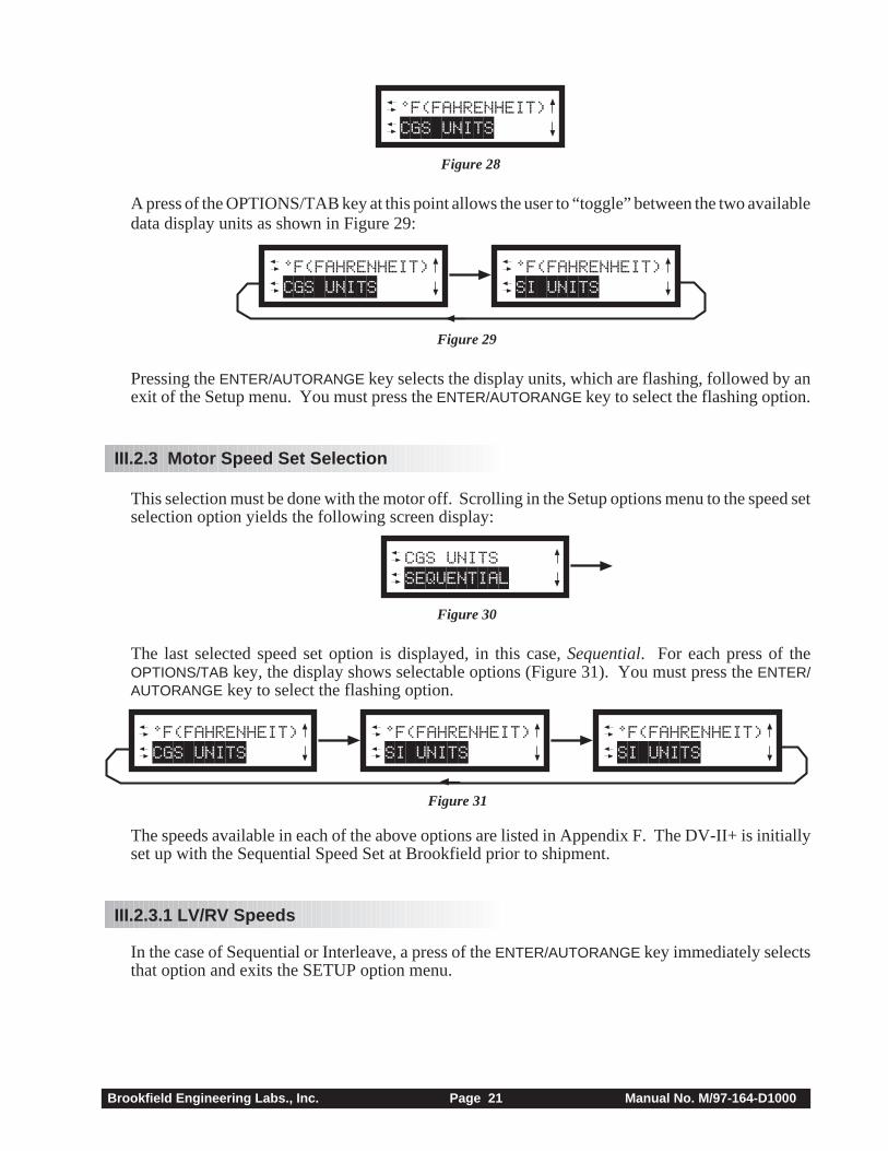
III.2.3 Motor Speed Set Selection
This selection must be done with the motor off. Scrolling in the Setup options menu to the speed setselection option yields the following screen display:
LCGS UNITS SEQUENTIAL
Figure 30
The last selected speed set option is displayed, in this case, Sequential. For each press of theOPTIONS/TAB key, the display shows selectable options (Figure 31). You must press the ENTER/AUTORANGE key to select the flashing option.
L°F(FAHRENHEIT) CGS UNITS
L°F(FAHRENHEIT) SI UNITS
L°F(FAHRENHEIT) SI UNITS
Figure 31
The speeds available in each of the above options are listed in Appendix F. The DV-II+ is initiallyset up with the Sequential Speed Set at Brookfield prior to shipment.
III.2.3.1 LV/RV Speeds
In the case of Sequential or Interleave, a press of the ENTER/AUTORANGE key immediately selectsthat option and exits the SETUP option menu.
Brookfield Engineering Labs., Inc. Page 22 Manual No. M/97-164-D1000
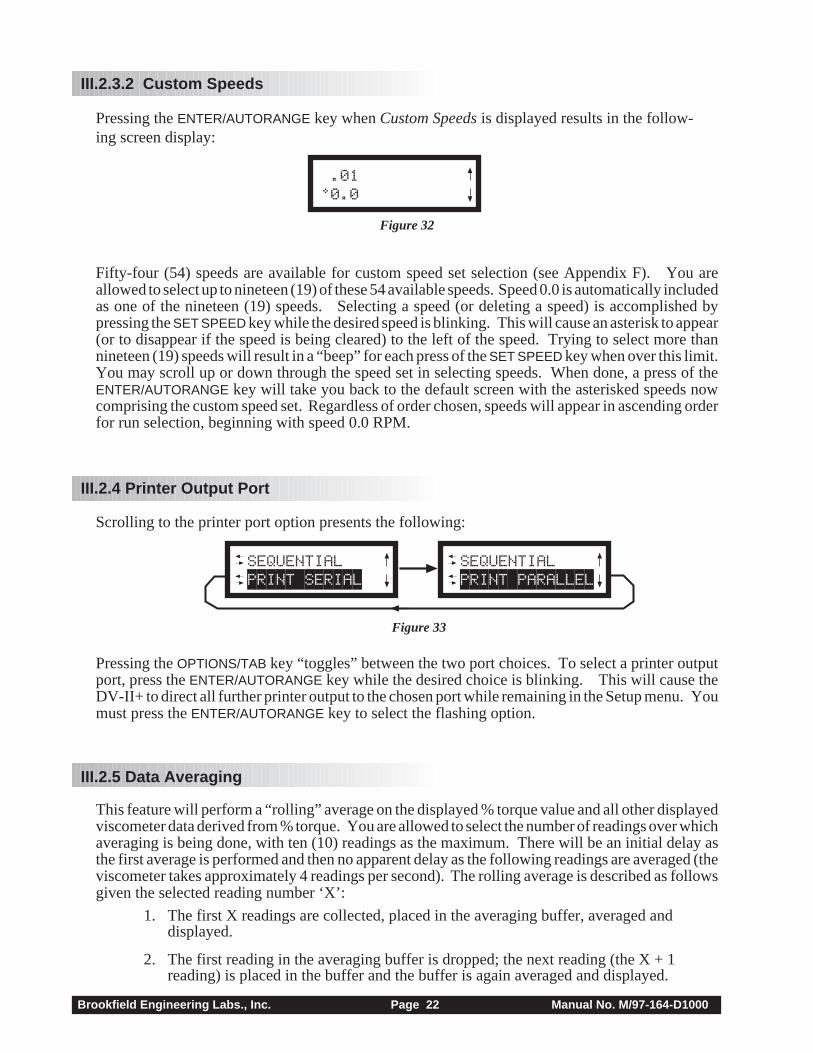
III.2.3.2 Custom Speeds
Pressing the ENTER/AUTORANGE key when Custom Speeds is displayed results in the follow-ing screen display:
.01°0.0
Figure 32
Fifty-four (54) speeds are available for custom speed set selection (see Appendix F). You areallowed to select up to nineteen (19) of these 54 available speeds. Speed 0.0 is automatically includedas one of the nineteen (19) speeds. Selecting a speed (or deleting a speed) is accomplished bypressing the SET SPEED key while the desired speed is blinking. This will cause an asterisk to appear(or to disappear if the speed is being cleared) to the left of the speed. Trying to select more thannineteen (19) speeds will result in a “beep” for each press of the SET SPEED key when over this limit.You may scroll up or down through the speed set in selecting speeds. When done, a press of theENTER/AUTORANGE key will take you back to the default screen with the asterisked speeds nowcomprising the custom speed set. Regardless of order chosen, speeds will appear in ascending orderfor run selection, beginning with speed 0.0 RPM.
III.2.4 Printer Output Port
Scrolling to the printer port option presents the following:
LSEQUENTIAL PRINT SERIAL
LSEQUENTIAL PRINT PARALLEL
Figure 33
Pressing the OPTIONS/TAB key “toggles” between the two port choices. To select a printer outputport, press the ENTER/AUTORANGE key while the desired choice is blinking. This will cause theDV-II+ to direct all further printer output to the chosen port while remaining in the Setup menu. Youmust press the ENTER/AUTORANGE key to select the flashing option.
III.2.5 Data Averaging
This feature will perform a “rolling” average on the displayed % torque value and all other displayedviscometer data derived from % torque. You are allowed to select the number of readings over whichaveraging is being done, with ten (10) readings as the maximum. There will be an initial delay asthe first average is performed and then no apparent delay as the following readings are averaged (theviscometer takes approximately 4 readings per second). The rolling average is described as followsgiven the selected reading number ‘X’:
1. The first X readings are collected, placed in the averaging buffer, averaged anddisplayed.
2. The first reading in the averaging buffer is dropped; the next reading (the X + 1reading) is placed in the buffer and the buffer is again averaged and displayed.
Brookfield Engineering Labs., Inc. Page 23 Manual No. M/97-164-D1000
Step 2 is repeated indefinitely until the viscometer is shut off or the user selects a different numberof readings to average. The number of readings to be averaged will include zero (0) as an averageso that this option may effectively be turned off without turning the viscometer off.
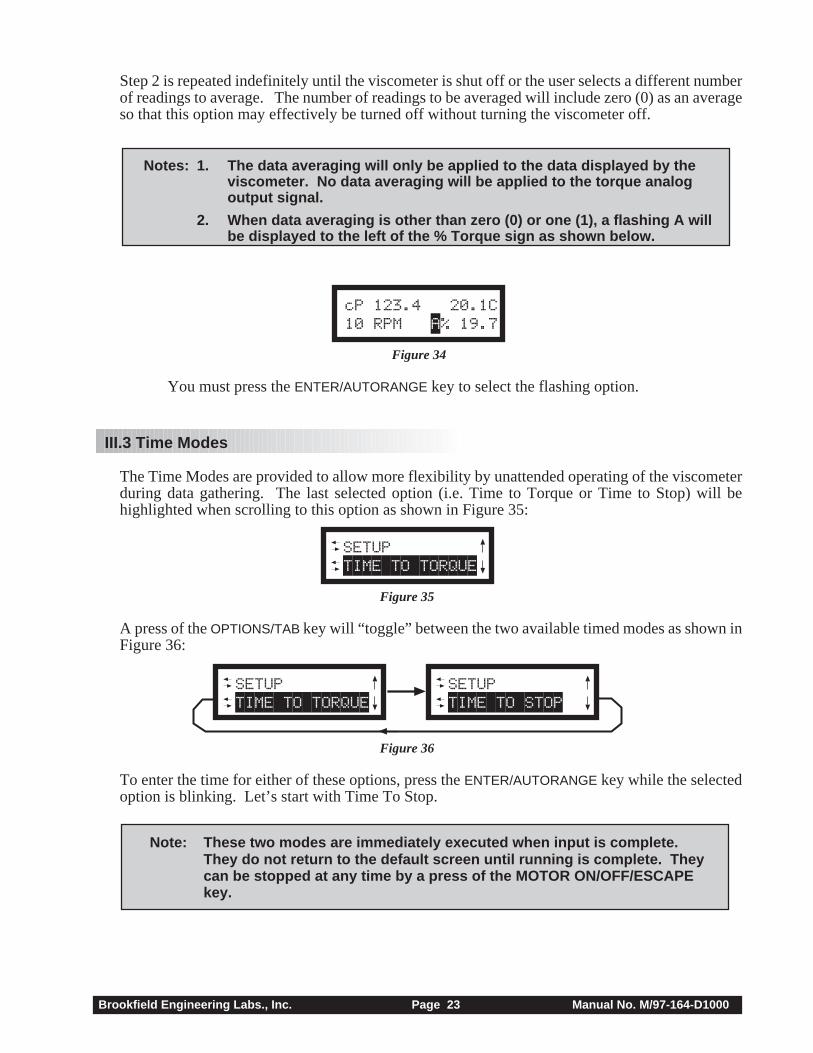
Notes: 1. The data averaging will only be applied to the data displayed by theviscometer. No data averaging will be applied to the torque analogoutput signal.
2. When data averaging is other than zero (0) or one (1), a flashing A willbe displayed to the left of the % Torque sign as shown below.
cP 123.4 20.1C10 RPM A% 19.7
Figure 34
You must press the ENTER/AUTORANGE key to select the flashing option.
III.3 Time Modes
The Time Modes are provided to allow more flexibility by unattended operating of the viscometerduring data gathering. The last selected option (i.e. Time to Torque or Time to Stop) will behighlighted when scrolling to this option as shown in Figure 35:
LSETUP TIME TO TORQUE
Figure 35
A press of the OPTIONS/TAB key will “toggle” between the two available timed modes as shown inFigure 36:
LSETUP TIME TO TORQUE
LSETUP TIME TO STOP
Figure 36
To enter the time for either of these options, press the ENTER/AUTORANGE key while the selectedoption is blinking. Let’s start with Time To Stop.
Note: These two modes are immediately executed when input is complete.They do not return to the default screen until running is complete. Theycan be stopped at any time by a press of the MOTOR ON/OFF/ESCAPEkey.
Brookfield Engineering Labs., Inc. Page 24 Manual No. M/97-164-D1000
III.3.1 Time to Stop
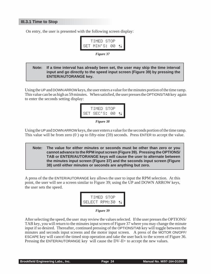
On entry, the user is presented with the following screen display:
TIMED STOPSET MIN’S: 00
Figure 37
Note: If a time interval has already been set, the user may skip the time intervalinput and go directly to the speed input screen (Figure 39) by pressing theENTER/AUTORANGE key.
Using the UP and DOWN ARROW keys, the user enters a value for the minutes portion of the time ramp.This value can be as high as 59 minutes. When satisfied, the user presses the OPTIONS/TAB key againto enter the seconds setting display:
TIMED STOPSET SEC’S: 00
Figure 38
Using the UP and DOWN ARROW keys, the user enters a value for the seconds portion of the time ramp.This value will be from zero (0 ) up to fifty-nine (59) seconds. Press ENTER to accept the value.
Note: The value for either minutes or seconds must be other than zero or youcannot advance to the RPM input screen (Figure 39). Pressing the OPTIONS/TAB or ENTER/AUTORANGE keys will cause the user to alternate betweenthe minutes input screen (Figure 37) and the seconds input screen (Figure38) until either minutes or seconds are anything but zero.
A press of the the ENTER/AUTORANGE key allows the user to input the RPM selection. At thispoint, the user will see a screen similar to Figure 39; using the UP and DOWN ARROW keys,the user sets the speed.
TIMED STOPSELECT RPM:30
Figure 39
After selecting the speed, the user may review the values selected. If the user presses the OPTIONS/TAB key, you will return to the minutes input screen of Figure 37 where you may change the minuteinput if so desired. Thereafter, continued pressing of the OPTIONS/TAB key will toggle between theminutes and seconds input screens and the motor input screen. A press of the MOTOR ON/OFF/ESCAPE key will cancel the timed stop operation and take the user back to the screen of Figure 36.Pressing the ENTER/AUTORANGE key will cause the DV-II+ to accept the new values.
Brookfield Engineering Labs., Inc. Page 25 Manual No. M/97-164-D1000
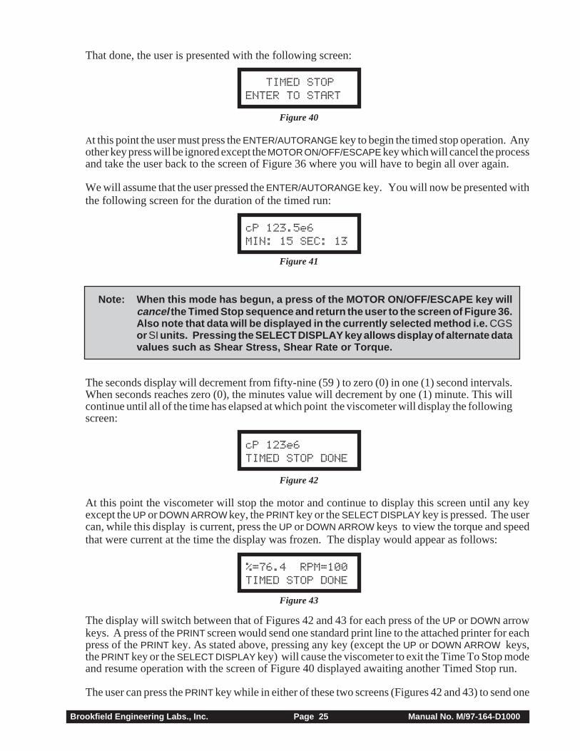
That done, the user is presented with the following screen:
TIMED STOPENTER TO START
Figure 40
At this point the user must press the ENTER/AUTORANGE key to begin the timed stop operation. Anyother key press will be ignored except the MOTOR ON/OFF/ESCAPE key which will cancel the processand take the user back to the screen of Figure 36 where you will have to begin all over again.
We will assume that the user pressed the ENTER/AUTORANGE key. You will now be presented withthe following screen for the duration of the timed run:
cP 123.5e6MIN: 15 SEC: 13
Figure 41
Note: When this mode has begun, a press of the MOTOR ON/OFF/ESCAPE key willcancel the Timed Stop sequence and return the user to the screen of Figure 36.Also note that data will be displayed in the currently selected method i.e. CGSor SI units. Pressing the SELECT DISPLAY key allows display of alternate datavalues such as Shear Stress, Shear Rate or Torque.
The seconds display will decrement from fifty-nine (59 ) to zero (0) in one (1) second intervals.When seconds reaches zero (0), the minutes value will decrement by one (1) minute. This willcontinue until all of the time has elapsed at which point the viscometer will display the followingscreen:
cP 123e6TIMED STOP DONE
Figure 42
At this point the viscometer will stop the motor and continue to display this screen until any keyexcept the UP or DOWN ARROW key, the PRINT key or the SELECT DISPLAY key is pressed. The usercan, while this display is current, press the UP or DOWN ARROW keys to view the torque and speedthat were current at the time the display was frozen. The display would appear as follows:
%=76.4 RPM=100TIMED STOP DONE
Figure 43
The display will switch between that of Figures 42 and 43 for each press of the UP or DOWN arrowkeys. A press of the PRINT screen would send one standard print line to the attached printer for eachpress of the PRINT key. As stated above, pressing any key (except the UP or DOWN ARROW keys,the PRINT key or the SELECT DISPLAY key) will cause the viscometer to exit the Time To Stop modeand resume operation with the screen of Figure 40 displayed awaiting another Timed Stop run.
The user can press the PRINT key while in either of these two screens (Figures 42 and 43) to send one

Brookfield Engineering Labs., Inc. Page 26 Manual No. M/97-164-D1000
standard print string to the attached printer as many times as the user presses the PRINT key. Inaddition, the PRINT key can be pressed during the actual measurement to obtain instantaneous data.Pressing any other key will exit this mode and return the viscometer to normal operation.
III.3.2 Time to Torque
On entry to this mode, the user is presented with the following screen display:
TIME TO TORQUESET TORQUE:00%
Figure 44
Using the UP or DOWN ARROW keys, the user enters a value for the torque level that you wish toreach.
Note: The value for torque must be other than zero (0) and less than or equalto ninety-nine (99) percent or you will not be able to continue.
At this point, the user presses the OPTIONS/TAB key and the screen shown in Figure 45 appears:
TIME TO TORQUESELECT RPM: 30
Figure 45
Using the UP or DOWN ARROW keys, the user selects a speed from the currently selected speed set.If you had opted to use the LVRV sequential or interleaved speed sets, all those speeds would beavailable by pressing the UP or DOWN ARROW keys. Conversely, if the user had selected a customspeed set, you would be limited to those speeds comprising the custom speed set. After selectingthe speed, the user may press any one of three keys to continue: the OPTIONS/TAB key, the MOTORON/OFF/ESCAPE key and the ENTER/AUTORANGE key. If the user presses the OPTIONS/TAB keyyou will return to the torque input screen of Figure 44 where you may change the torque input if sodesired. Therefore, continued pressing of the OPTIONS/TAB key will toggle between the torque inputscreens and the motor input screen. A press of the MOTOR ON/OFF/ESCAPE key will cancel the timeto torque operation and take the user back to the screen of Figure 35. Finally, pressing the ENTER/AUTORANGE key will cause the DV-II+ to accept and store in EEPROM the new values (only) forthe torque level and the selected motor speed.
That done, the user is presented with the following screen:
TIME TO TORQUEENTER TO START
Figure 46
At this point the user must press the ENTER/AUTORANGE key to begin the timed stop operation. Anyother key press will be ignored except the MOTOR ON/OFF/ESCAPE key which will cancel theprocess and take the user back to the screen of Figure 44 where you will have to begin all over again.
We will assume that the user pressed the ENTER/AUTORANGE key. You will now be presented with
Brookfield Engineering Labs., Inc. Page 27 Manual No. M/97-164-D1000
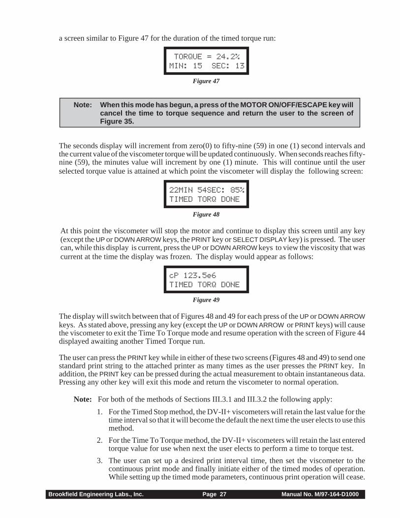
a screen similar to Figure 47 for the duration of the timed torque run:
TORQUE = 24.2%MIN: 15 SEC: 13
Figure 47
Note: When this mode has begun, a press of the MOTOR ON/OFF/ESCAPE key willcancel the time to torque sequence and return the user to the screen ofFigure 35.
The seconds display will increment from zero(0) to fifty-nine (59) in one (1) second intervals andthe current value of the viscometer torque will be updated continuously. When seconds reaches fifty-nine (59), the minutes value will increment by one (1) minute. This will continue until the userselected torque value is attained at which point the viscometer will display the following screen:
22MIN 54SEC: 85%TIMED TORQ DONE
Figure 48
At this point the viscometer will stop the motor and continue to display this screen until any key(except the UP or DOWN ARROW keys, the PRINT key or SELECT DISPLAY key) is pressed. The usercan, while this display is current, press the UP or DOWN ARROW keys to view the viscosity that wascurrent at the time the display was frozen. The display would appear as follows:
cP 123.5e6TIMED TORQ DONE
Figure 49
The display will switch between that of Figures 48 and 49 for each press of the UP or DOWN ARROWkeys. As stated above, pressing any key (except the UP or DOWN ARROW or PRINT keys) will causethe viscometer to exit the Time To Torque mode and resume operation with the screen of Figure 44displayed awaiting another Timed Torque run.
The user can press the PRINT key while in either of these two screens (Figures 48 and 49) to send onestandard print string to the attached printer as many times as the user presses the PRINT key. Inaddition, the PRINT key can be pressed during the actual measurement to obtain instantaneous data.Pressing any other key will exit this mode and return the viscometer to normal operation.
Note: For both of the methods of Sections III.3.1 and III.3.2 the following apply:
1. For the Timed Stop method, the DV-II+ viscometers will retain the last value for thetime interval so that it will become the default the next time the user elects to use thismethod.
2. For the Time To Torque method, the DV-II+ viscometers will retain the last enteredtorque value for use when next the user elects to perform a time to torque test.
3. The user can set up a desired print interval time, then set the viscometer to thecontinuous print mode and finally initiate either of the timed modes of operation.While setting up the timed mode parameters, continuous print operation will cease.
Brookfield Engineering Labs., Inc. Page 28 Manual No. M/97-164-D1000
However, upon starting the timed operation, the DV-II+ will output an initial datastring to the printer and then continue printing data strings (at the user defined timeinterval) for the duration of the timed run. At the end of the timed run, continuousprinting will again be disabled and the user may print single strings (of the final datapoint) at your option until you exit the timed mode. Upon returning to the defaultoperation mode, continous printing will again resume at the user selected timeinterval. In a similar manner, if you are in the once-per-PRINT -key-press mode,when you enter the timed mode of operation you will be able to print data strings atany time during the timed mode by pressing the PRINT key.
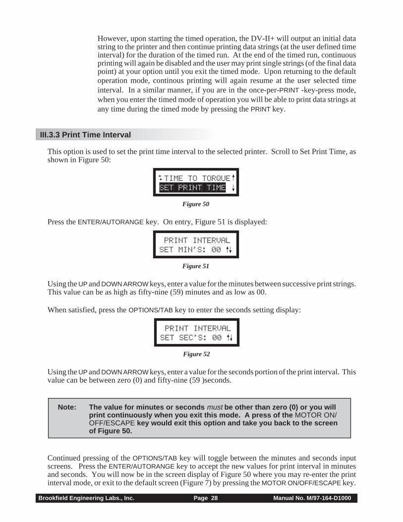
III.3.3 Print Time Interval
This option is used to set the print time interval to the selected printer. Scroll to Set Print Time, asshown in Figure 50:
LTIME TO TORQUESET PRINT TIME
Figure 50
Press the ENTER/AUTORANGE key. On entry, Figure 51 is displayed:
LPRINT INTERVALSET MIN’S: 00
Figure 51
Using the UP and DOWN ARROW keys, enter a value for the minutes between successive print strings.This value can be as high as fifty-nine (59) minutes and as low as 00.
When satisfied, press the OPTIONS/TAB key to enter the seconds setting display:
LPRINT INTERVALSET SEC’S: 00
Figure 52
Using the UP and DOWN ARROW keys, enter a value for the seconds portion of the print interval. Thisvalue can be between zero (0) and fifty-nine (59 )seconds.
Note: The value for minutes or seconds must be other than zero (0) or you willprint continuously when you exit this mode. A press of the MOTOR ON/OFF/ESCAPE key would exit this option and take you back to the screenof Figure 50.
Continued pressing of the OPTIONS/TAB key will toggle between the minutes and seconds inputscreens. Press the ENTER/AUTORANGE key to accept the new values for print interval in minutesand seconds. You will now be in the screen display of Figure 50 where you may re-enter the printinterval mode, or exit to the default screen (Figure 7) by pressing the MOTOR ON/OFF/ESCAPE key.

Brookfield Engineering Labs., Inc. Page 29 Manual No. M/97-164-D1000
Activating print selections in the Print mode can only be done by exiting to the main menu andpressing the PRINT key for four (4) seconds. “P%” will flash in front of the torque reading,confirming that you are now in the Print Interval mode. Pressing PRINT for one (1) secondthereafter will disable the Print mode and remove the “P%” from the display.
III.3.4 PC Program (On/Off)
This option causes the serial port of the DV-II+ viscometer to go into a high speed output mode(approximately 3 print lines per second) for use with Brookfield WINGATHER® Version 1.1software program. When ON, you may enter the Options menu but will not be allowed to make anyoption selections until the PC PROG is turned OFF. All front panel keys will function normally whenyou turn the option ON and return to normal viscometer operation by pressing the MOTOR ON/OFF/ESCAPE key. When OFF, the DV-II+ will return to the last set print time interval when printing isresumed.
From the Options menu, scroll to the screen shown in Figure 53:
SET PRINT TIME PC PROG OFF
Figure 53
Press the OPTIONS/TAB key to display Figure 54:
SET PRINT TIME PC PROG ON
Figure 54
Pressing the OPTIONS/TAB key would return you to the screen display of Figure 53. Repeatedpressing of the OPTIONS/TAB key would cause you to toggle back-and-forth between the displays ofFigure 53 and Figure 54.
To turn high speed output ON, press the ENTER/AUTORANGE key when the appropriate screen isdisplayed. Then press the MOTOR ON/OFF/ESCAPE key to exit the Setup mode. This returns youto the default screen display and resumes normal viscometer operation with high speed outputenabled and normal printer operation using the last entered print time interval.
Note: For access to B.E.V.I.S. option, PC PROG must be OFF.
III.3.5 Download a Program
Please refer to Section IV for details on how to create a program before proceeding with this section.
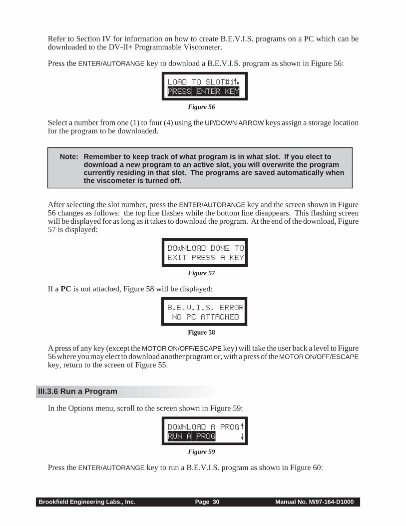
In the Options menu, scroll to the screen shown in Figure 55:
PC PROG OFFDOWNLOAD A PROG
Figure 55
Brookfield Engineering Labs., Inc. Page 30 Manual No. M/97-164-D1000
Refer to Section IV for information on how to create B.E.V.I.S. programs on a PC which can bedownloaded to the DV-II+ Programmable Viscometer.
Press the ENTER/AUTORANGE key to download a B.E.V.I.S. program as shown in Figure 56:
LOAD TO SLOT#1PRESS ENTER KEY
Figure 56
Select a number from one (1) to four (4) using the UP/DOWN ARROW keys assign a storage locationfor the program to be downloaded.
Note: Remember to keep track of what program is in what slot. If you elect todownload a new program to an active slot, you will overwrite the programcurrently residing in that slot. The programs are saved automatically whenthe viscometer is turned off.
After selecting the slot number, press the ENTER/AUTORANGE key and the screen shown in Figure56 changes as follows: the top line flashes while the bottom line disappears. This flashing screenwill be displayed for as long as it takes to download the program. At the end of the download, Figure57 is displayed:
DOWNLOAD DONE TOEXIT PRESS A KEY
Figure 57
If a PC is not attached, Figure 58 will be displayed:
B.E.V.I.S. ERROR NO PC ATTACHED
Figure 58
A press of any key (except the MOTOR ON/OFF/ESCAPE key) will take the user back a level to Figure56 where you may elect to download another program or, with a press of the MOTOR ON/OFF/ESCAPEkey, return to the screen of Figure 55.
III.3.6 Run a Program
In the Options menu, scroll to the screen shown in Figure 59:
DOWNLOAD A PROGRUN A PROG
Figure 59
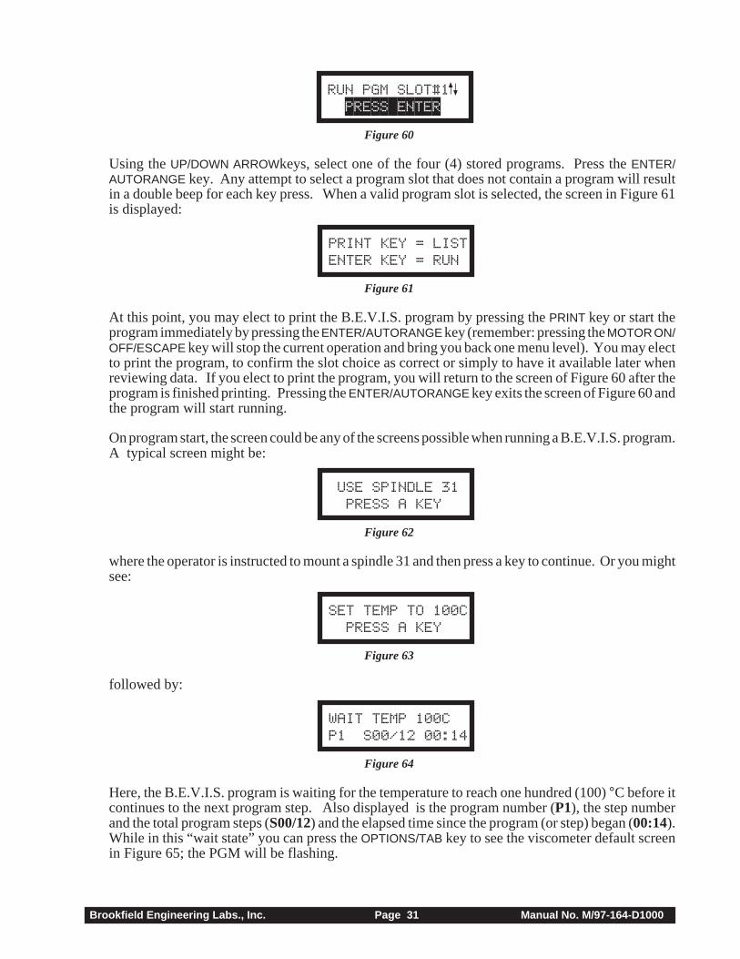
Press the ENTER/AUTORANGE key to run a B.E.V.I.S. program as shown in Figure 60:
Brookfield Engineering Labs., Inc. Page 31 Manual No. M/97-164-D1000
RUN PGM SLOT#1 PRESS ENTER
Figure 60
Using the UP/DOWN ARROWkeys, select one of the four (4) stored programs. Press the ENTER/AUTORANGE key. Any attempt to select a program slot that does not contain a program will resultin a double beep for each key press. When a valid program slot is selected, the screen in Figure 61is displayed:
PRINT KEY = LISTENTER KEY = RUN
Figure 61
At this point, you may elect to print the B.E.V.I.S. program by pressing the PRINT key or start theprogram immediately by pressing the ENTER/AUTORANGE key (remember: pressing the MOTOR ON/OFF/ESCAPE key will stop the current operation and bring you back one menu level). You may electto print the program, to confirm the slot choice as correct or simply to have it available later whenreviewing data. If you elect to print the program, you will return to the screen of Figure 60 after theprogram is finished printing. Pressing the ENTER/AUTORANGE key exits the screen of Figure 60 andthe program will start running.
On program start, the screen could be any of the screens possible when running a B.E.V.I.S. program.A typical screen might be:
USE SPINDLE 31 PRESS A KEY
Figure 62
where the operator is instructed to mount a spindle 31 and then press a key to continue. Or you mightsee:
SET TEMP TO 100C PRESS A KEY
Figure 63
followed by:
WAIT TEMP 100CP1 S00/12 00:14
Figure 64
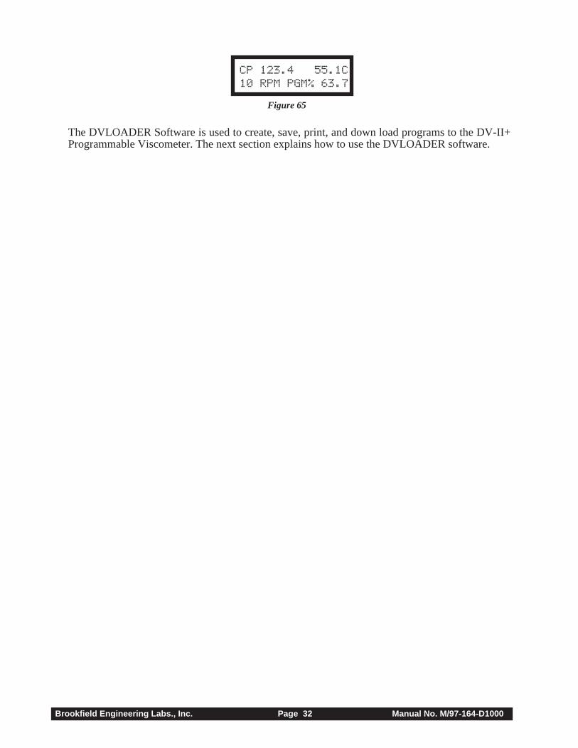
Here, the B.E.V.I.S. program is waiting for the temperature to reach one hundred (100) °C before itcontinues to the next program step. Also displayed is the program number (P1), the step numberand the total program steps (S00/12) and the elapsed time since the program (or step) began (00:14).While in this “wait state” you can press the OPTIONS/TAB key to see the viscometer default screenin Figure 65; the PGM will be flashing.
Brookfield Engineering Labs., Inc. Page 32 Manual No. M/97-164-D1000
CP 123.4 55.1C10 RPM PGM% 63.7
Figure 65
The DVLOADER Software is used to create, save, print, and down load programs to the DV-II+Programmable Viscometer. The next section explains how to use the DVLOADER software.
Brookfield Engineering Labs., Inc. Page 33 Manual No. M/97-164-D1000
IV. DVLOADER SOFTWARE
The DVLOADER software is a WINDOWS-based program provided on a 3-1/2" diskette whichcomes with the Programmable DV-II+ Viscometer.
IV.1 B.E.V.I.S. Overview
DVLOADER utilizes B.E.V.I.S. (Brookfield Engineering Viscometer Instruction Set), a script-ing language that allows for the creation of programs to control the Programmable DV-II+Viscometer. Programs are created on a PC, then loaded into the viscometer using the DVLoadersoftware. Some testing capabilities that are possible include the following:
• Repeatedly run the same test program for quality control purposes.
• Wait for a specific condition before continuing with the test (i.e. a torque value, a tempera-ture value, a key press, etc.).
• Run the viscometer at any of the speeds in the Custom Speed menu.
• Display messages to the screen or an attached printer to aid the operator.
• An internal clock that keeps time between each printed data line (this time is displayed as thelast parameter on each printed line). This provides a consistent time base for the collecteddata.

Brookfield Engineering Labs., Inc. Page 34 Manual No. M/97-164-D1000
IV.2 Description of B.E.V.I.S. Commands
Command Code Required Parameter Command DescriptionWTI Time The program waits at this step until the specified time
(MM:SS) elapses.WPT % Torque value The program waits at this step until the current % torque
(%) equals the specifed value.WTP Temperature value The program waits at this step until the current temperature
(°C) equals the specified value.WKY 16 character (or less) The specified message is displayed on the top line of the DV-
text message II+ display while PRESS A KEY is displayed on the bottomline of the DV-II+. The program waits at this step until aviscometer key is pressed. While waiting at this step, theviscometer produces a beep every few seconds to remind theoperator that a keypress is required to continue.If a print interval was enabled (see SPI) at the time thiscommand is executed, the data print timer continues to countup. If the print interval elapses and a key has not yet beenpressed, a line of data displaying the time since the last dataprint is printed as soon as a key is pressed.
SSN Speed value The DV-II+ begins rotating at the specified speed. This can(RPM) be any of the speeds listed in the Speed list of the DVLoader
software. These speeds are the same as those listed in theCustom Speeds list in the viscometer’s Options menu.
SPI Time The DV-II+ begins printing data to the selected printer (serial(MM:SS) or parallel; as selected in the DV-II+ menus) at the rate
specified. MM:SS is minutes:seconds.SSP Two digit spindle code Calculations of viscosity, shear stress, and shear rate are
performed based on the specified spindle code. Thiscommand overrides the spindle currently entered via thekeypad on the DV-II+.
STZ N/A Sets the data print timer clock back to zero.PDN N/A The DV-II+ immediately prints a data string to the selected
printer (serial or parallel; as selected in the DV-II+ menus).PLN 16 character (or less) The DV-II+ prints the specified message to the selected
text message printer (serial or parallel; as selected in the DV-II+ menus).
By using various combinations of the above commands, programs are created that automaticallycontrol the viscometer and collect data (via an attached printer) from the Programmable DV-II+Viscometer.
Brookfield Engineering Labs., Inc. Page 35 Manual No. M/97-164-D1000
IV.3 Creating a B.E.V.I.S. Program
Start the DVLOADER software by clicking on its associated icon or by using the File|Run option ofthe Windows 3.1 Program Manager. For Windows 95, click the Start button; select Run; enter thename of the program to execute {dvloader.exe}; then click OK.
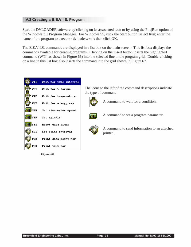
The B.E.V.I.S. commands are displayed in a list box on the main screen. This list box displays thecommands available for creating programs. Clicking on the Insert button inserts the highlightedcommand (WTI, as shown in Figure 66) into the selected line in the program grid. Double-clickingon a line in this list box also inserts the command into the grid shown in Figure 67.
The icons to the left of the command descriptions indicatethe type of command:
A command to wait for a condition.
A command to set a program parameter.
A command to send information to an attachedprinter.
Figure 66
Brookfield Engineering Labs., Inc. Page 36 Manual No. M/97-164-D1000
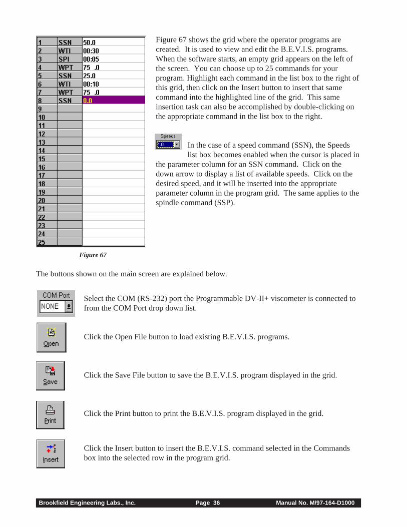
Figure 67 shows the grid where the operator programs arecreated. It is used to view and edit the B.E.V.I.S. programs.When the software starts, an empty grid appears on the left ofthe screen. You can choose up to 25 commands for yourprogram. Highlight each command in the list box to the right ofthis grid, then click on the Insert button to insert that samecommand into the highlighted line of the grid. This sameinsertion task can also be accomplished by double-clicking onthe appropriate command in the list box to the right.
In the case of a speed command (SSN), the Speedslist box becomes enabled when the cursor is placed in
the parameter column for an SSN command. Click on thedown arrow to display a list of available speeds. Click on thedesired speed, and it will be inserted into the appropriateparameter column in the program grid. The same applies to thespindle command (SSP).
Select the COM (RS-232) port the Programmable DV-II+ viscometer is connected tofrom the COM Port drop down list.
Click the Open File button to load existing B.E.V.I.S. programs.
Click the Save File button to save the B.E.V.I.S. program displayed in the grid.
Click the Print button to print the B.E.V.I.S. program displayed in the grid.
Click the Insert button to insert the B.E.V.I.S. command selected in the Commandsbox into the selected row in the program grid.
The buttons shown on the main screen are explained below.
Figure 67
Brookfield Engineering Labs., Inc. Page 37 Manual No. M/97-164-D1000
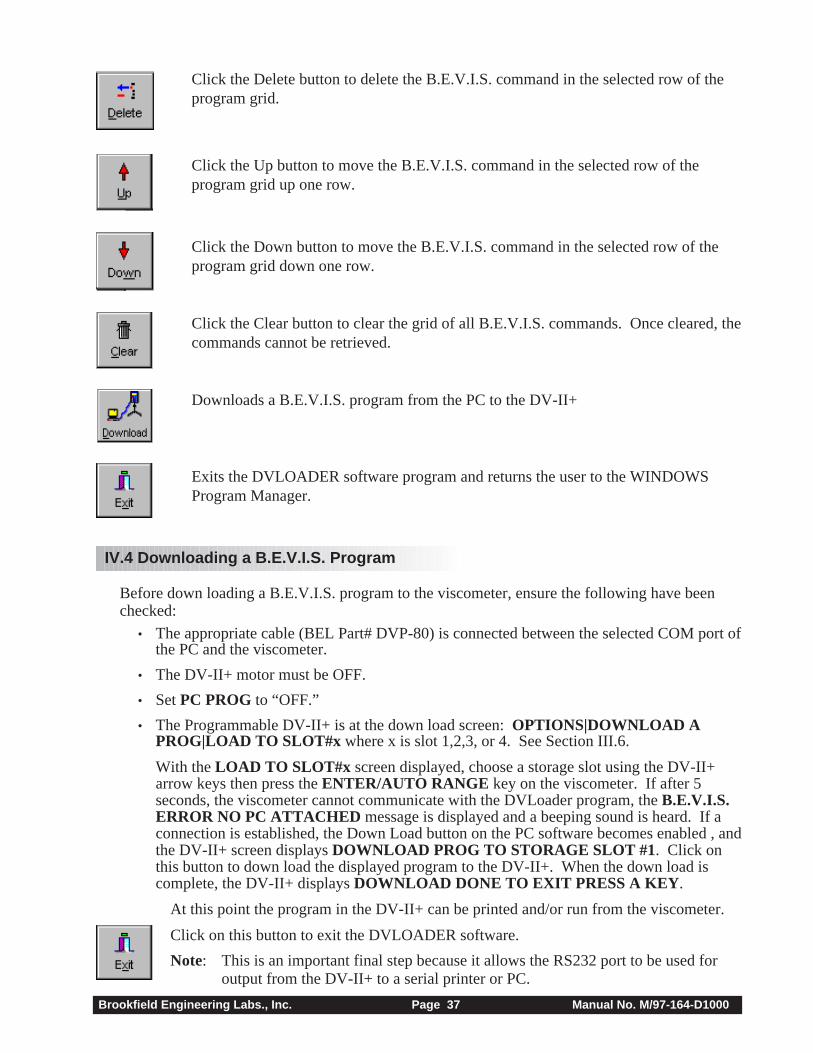
Click the Delete button to delete the B.E.V.I.S. command in the selected row of theprogram grid.
Click the Up button to move the B.E.V.I.S. command in the selected row of theprogram grid up one row.
Click the Down button to move the B.E.V.I.S. command in the selected row of theprogram grid down one row.
Click the Clear button to clear the grid of all B.E.V.I.S. commands. Once cleared, thecommands cannot be retrieved.
Downloads a B.E.V.I.S. program from the PC to the DV-II+
Exits the DVLOADER software program and returns the user to the WINDOWSProgram Manager.
IV.4 Downloading a B.E.V.I.S. Program
Before down loading a B.E.V.I.S. program to the viscometer, ensure the following have beenchecked:
• The appropriate cable (BEL Part# DVP-80) is connected between the selected COM port ofthe PC and the viscometer.
• The DV-II+ motor must be OFF.
• Set PC PROG to “OFF.”
• The Programmable DV-II+ is at the down load screen: OPTIONS|DOWNLOAD APROG|LOAD TO SLOT#x where x is slot 1,2,3, or 4. See Section III.6.
With the LOAD TO SLOT#x screen displayed, choose a storage slot using the DV-II+arrow keys then press the ENTER/AUTO RANGE key on the viscometer. If after 5seconds, the viscometer cannot communicate with the DVLoader program, the B.E.V.I.S.ERROR NO PC ATTACHED message is displayed and a beeping sound is heard. If aconnection is established, the Down Load button on the PC software becomes enabled , andthe DV-II+ screen displays DOWNLOAD PROG TO STORAGE SLOT #1. Click onthis button to down load the displayed program to the DV-II+. When the down load iscomplete, the DV-II+ displays DOWNLOAD DONE TO EXIT PRESS A KEY .
At this point the program in the DV-II+ can be printed and/or run from the viscometer.
Click on this button to exit the DVLOADER software.
Note: This is an important final step because it allows the RS232 port to be used foroutput from the DV-II+ to a serial printer or PC.
Brookfield Engineering Labs., Inc. Page 38 Manual No. M/97-164-D1000
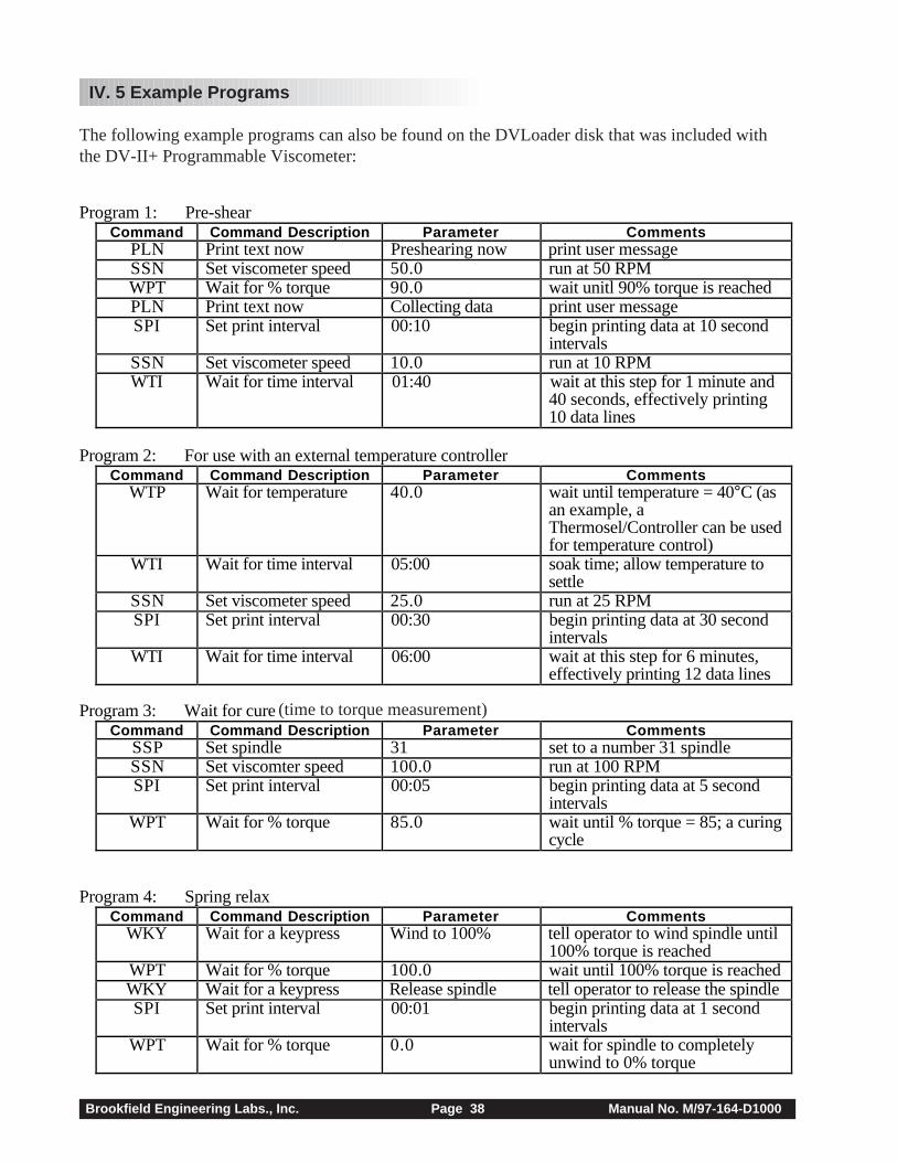
Program 2: For use with an external temperature controllerCommand Command Description Parameter Comments
WTP Wait for temperature 40.0 wait until temperature = 40°C (asan example, aThermosel/Controller can be usedfor temperature control)
WTI Wait for time interval 05:00 soak time; allow temperature tosettle
SSN Set viscometer speed 25.0 run at 25 RPMSPI Set print interval 00:30 begin printing data at 30 second
intervalsWTI Wait for time interval 06:00 wait at this step for 6 minutes,
effectively printing 12 data lines
Program 3: Wait for cureCommand Command Description Parameter Comments
SSP Set spindle 31 set to a number 31 spindleSSN Set viscomter speed 100.0 run at 100 RPMSPI Set print interval 00:05 begin printing data at 5 second
intervalsWPT Wait for % torque 85.0 wait until % torque = 85; a curing
cycle
Program 4: Spring relaxCommand Command Description Parameter Comments
WKY Wait for a keypress Wind to 100% tell operator to wind spindle until100% torque is reached
WPT Wait for % torque 100.0 wait until 100% torque is reachedWKY Wait for a keypress Release spindle tell operator to release the spindleSPI Set print interval 00:01 begin printing data at 1 second
intervalsWPT Wait for % torque 0.0 wait for spindle to completely
unwind to 0% torque
Program 1: Pre-shearCommand Command Description Parameter Comments
PLN Print text now Preshearing now print user messageSSN Set viscometer speed 50.0 run at 50 RPMWPT Wait for % torque 90.0 wait unitl 90% torque is reachedPLN Print text now Collecting data print user messageSPI Set print interval 00:10 begin printing data at 10 second
intervalsSSN Set viscometer speed 10.0 run at 10 RPMWTI Wait for time interval 01:40 wait at this step for 1 minute and
40 seconds, effectively printing10 data lines
IV. 5 Example Programs
The following example programs can also be found on the DVLoader disk that was included withthe DV-II+ Programmable Viscometer:
(time to torque measurement)
Brookfield Engineering Labs., Inc. Page 39 Manual No. M/97-164-D1000
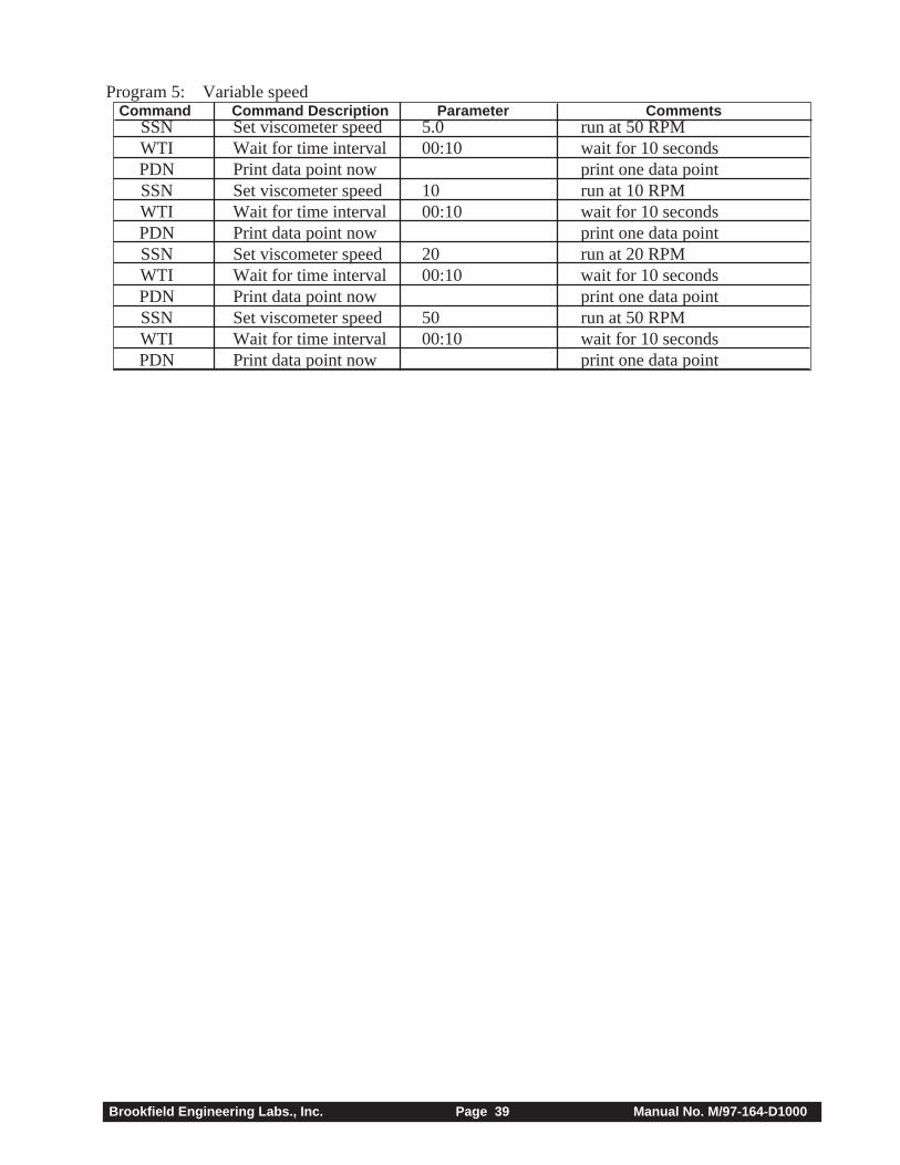
SSN Set viscometer speed 5.0 run at 50 RPMWTI Wait for time interval 00:10 wait for 10 secondsPDN Print data point now print one data pointSSN Set viscometer speed 10 run at 10 RPMWTI Wait for time interval 00:10 wait for 10 secondsPDN Print data point now print one data pointSSN Set viscometer speed 20 run at 20 RPMWTI Wait for time interval 00:10 wait for 10 secondsPDN Print data point now print one data pointSSN Set viscometer speed 50 run at 50 RPMWTI Wait for time interval 00:10 wait for 10 secondsPDN Print data point now print one data point
Command Command Description Parameter CommentsProgram 5: Variable speed
Brookfield Engineering Labs., Inc. Page 40 Manual No. M/97-164-D1000
Appendix A - Cone/Plate Viscometer Set-Up
This Cone/Plate version of the DV-II+ uses the same operating instruction procedures as describedin this manual. However, the “gap” between the cone and the plate must be verified/adjusted beforemeasurements are made. This is done by moving the plate (built into the sample cup) up towards thecone until the pin in the center of the cone touches the surface of the plate, and then by separating(lowering) the plate 0.0005 inch (0.013mm).
Programmable DV-II+ Cone/Plate Viscometers, S/N 50969 and higher, have an Electronic GapSetting feature. This feature enables the user to easily find the 0.0005 inch gap setting that wasestablished at Brookfield prior to shipment.
The following information explains how to set the Electronic Gap and verify calibration of the DV-II+ Viscometer.
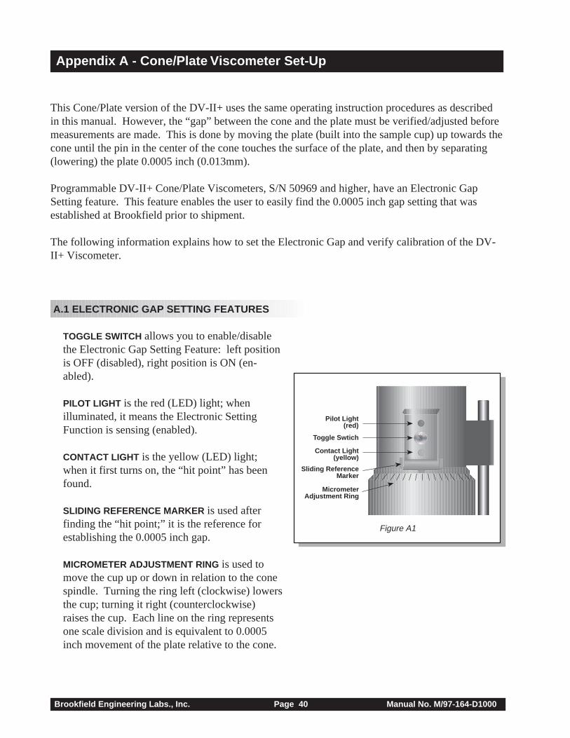
A.1 ELECTRONIC GAP SETTING FEATURES
TOGGLE SWITCH allows you to enable/disablethe Electronic Gap Setting Feature: left positionis OFF (disabled), right position is ON (en-abled).
PILOT LIGHT is the red (LED) light; whenilluminated, it means the Electronic SettingFunction is sensing (enabled).
CONTACT LIGHT is the yellow (LED) light;when it first turns on, the “hit point” has beenfound.
SLIDING REFERENCE MARKER is used afterfinding the “hit point;” it is the reference forestablishing the 0.0005 inch gap.
MICROMETER ADJUSTMENT RING is used tomove the cup up or down in relation to the conespindle. Turning the ring left (clockwise) lowersthe cup; turning it right (counterclockwise)raises the cup. Each line on the ring representsone scale division and is equivalent to 0.0005inch movement of the plate relative to the cone.
Pilot Light(red)
Toggle Swtich
Contact Light(yellow)
Sliding ReferenceMarker
MicrometerAdjustment Ring
Figure A1
Brookfield Engineering Labs., Inc. Page 41 Manual No. M/97-164-D1000
Bath/Circulator
BathInlet
BathOutlet
SampleCup
(CPE-44Yor
CPE-44P)
CupOutlet
CupInlet
Figure A2
Figure A3
SpindleWrench
(CPE) Cone
These surfacesmust be clean!
Coupling Nut
MicrometerAdjustment
Ring
Do Not hit theCONE with the CUP!
Figure A4
A.2 SETUP
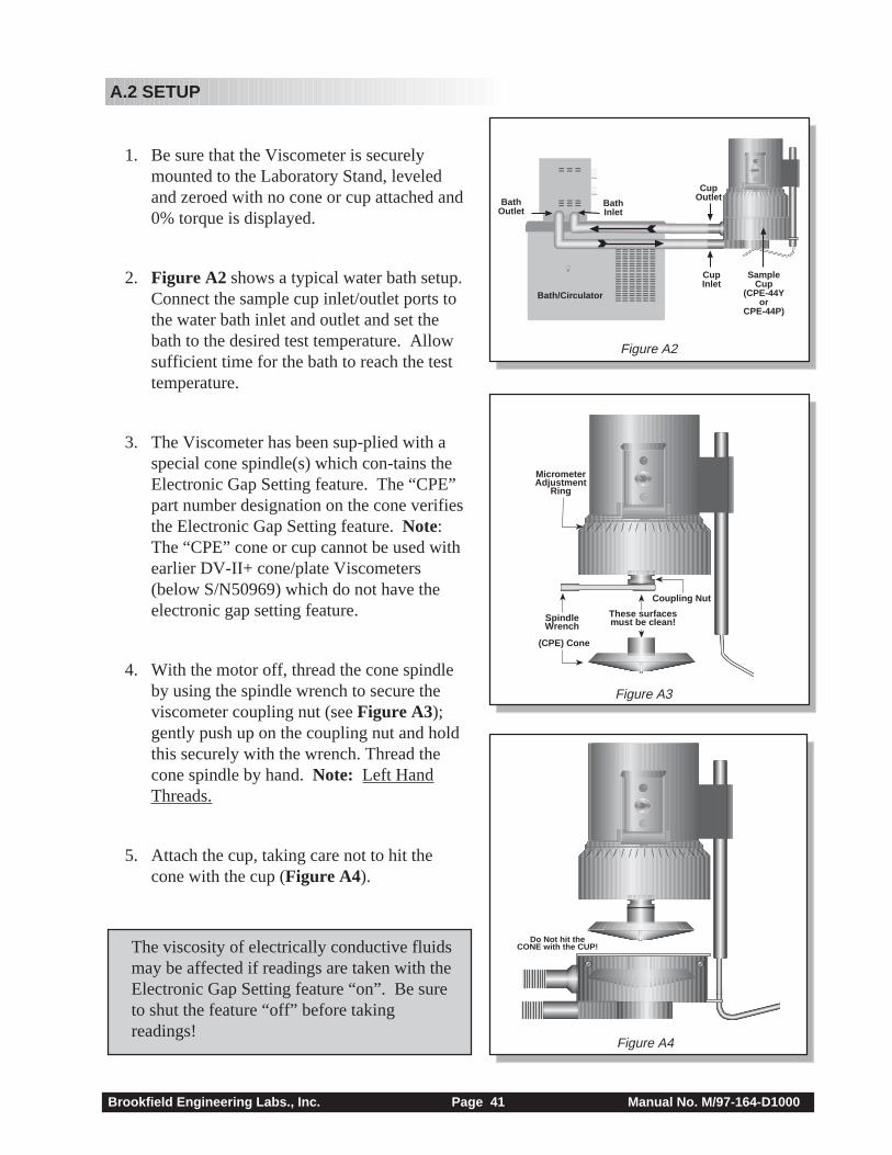
1. Be sure that the Viscometer is securelymounted to the Laboratory Stand, leveledand zeroed with no cone or cup attached and0% torque is displayed.
2. Figure A2 shows a typical water bath setup.Connect the sample cup inlet/outlet ports tothe water bath inlet and outlet and set thebath to the desired test temperature. Allowsufficient time for the bath to reach the testtemperature.
3. The Viscometer has been sup-plied with aspecial cone spindle(s) which con-tains theElectronic Gap Setting feature. The “CPE”part number designation on the cone verifiesthe Electronic Gap Setting feature. Note:The “CPE” cone or cup cannot be used withearlier DV-II+ cone/plate Viscometers(below S/N50969) which do not have theelectronic gap setting feature.
4. With the motor off, thread the cone spindleby using the spindle wrench to secure theviscometer coupling nut (see Figure A3);gently push up on the coupling nut and holdthis securely with the wrench. Thread thecone spindle by hand. Note: Left HandThreads.
5. Attach the cup, taking care not to hit thecone with the cup (Figure A4).
The viscosity of electrically conductive fluidsmay be affected if readings are taken with theElectronic Gap Setting feature “on”. Be sureto shut the feature “off” before takingreadings!
Brookfield Engineering Labs., Inc. Page 42 Manual No. M/97-164-D1000
A.3 SETTING THE GAP
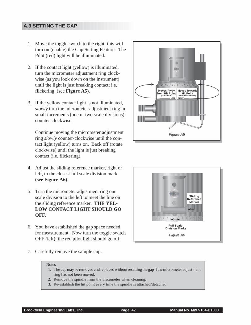
1. Move the toggle switch to the right; this willturn on (enable) the Gap Setting Feature. ThePilot (red) light will be illuminated.
2. If the contact light (yellow) is illuminated,turn the micrometer adjustment ring clock-wise (as you look down on the instrument)until the light is just breaking contact; i.e.flickering. (see Figure A5).
3. If the yellow contact light is not illuminated,slowly turn the micrometer adjustment ring insmall increments (one or two scale divisions)counter-clockwise.
Continue moving the micrometer adjustmentring slowly counter-clockwise until the con-tact light (yellow) turns on. Back off (rotateclockwise) until the light is just breakingcontact (i.e. flickering).
4. Adjust the sliding reference marker, right orleft, to the closest full scale division mark(see Figure A6).
5. Turn the micrometer adjustment ring onescale division to the left to meet the line onthe sliding reference marker. THE YEL-LOW CONTACT LIGHT SHOULD GOOFF.
6. You have established the gap space neededfor measurement. Now turn the toggle switchOFF (left); the red pilot light should go off.
7. Carefully remove the sample cup.
Moves Awayfrom Hit Point
(clockwise) LEFTx
Moves Towards Hit Point
(counter-clockwise) RIGHT
Full Scale Division Marks
SlidingReference
Marker
Figure A5
Figure A6
Notes1. The cup may be removed and replaced without resetting the gap if the micrometer adjustment
ring has not been moved.2. Remove the spindle from the viscometer when cleaning.3. Re-establish the hit point every time the spindle is attached/detached.
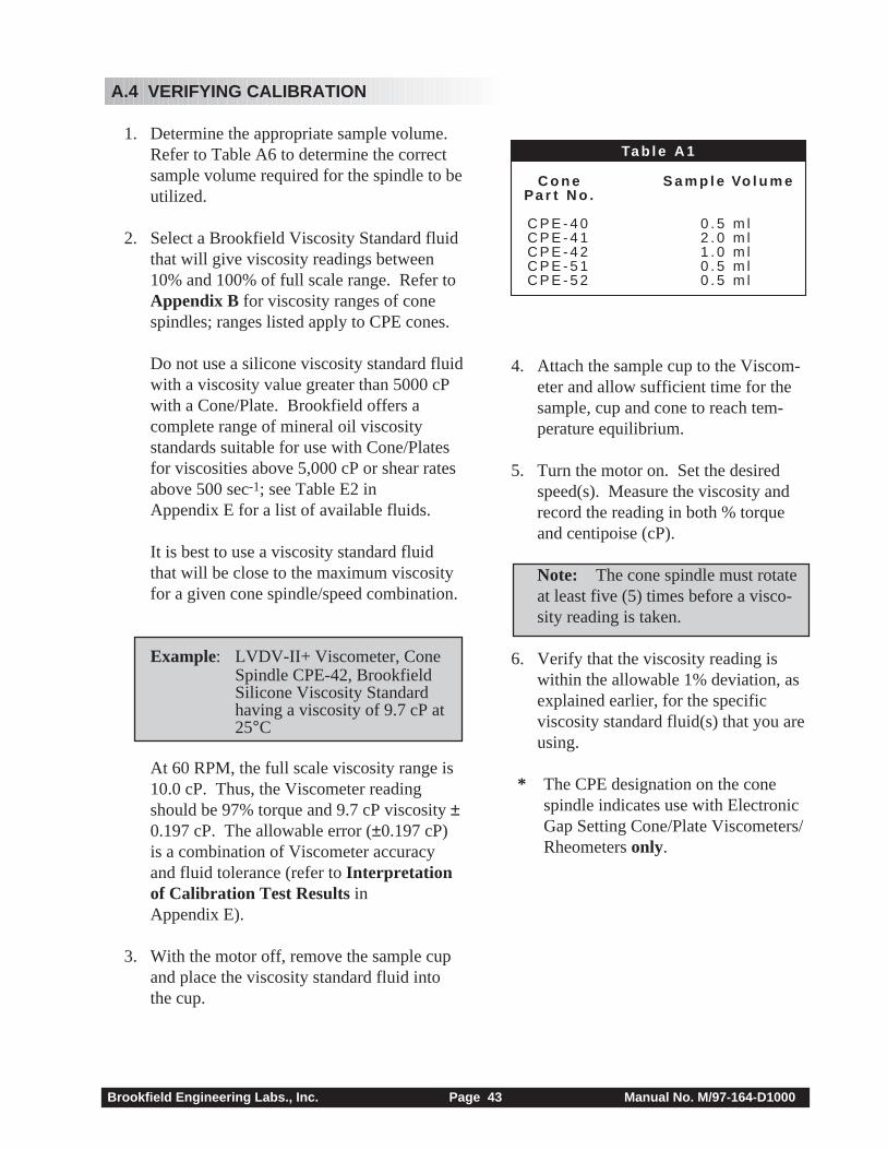
Brookfield Engineering Labs., Inc. Page 43 Manual No. M/97-164-D1000
C o n e S a m p l e Vo l u m ePa r t N o .
C P E - 4 0 0 . 5 m lC P E - 4 1 2 . 0 m lC P E - 4 2 1 . 0 m lC P E - 5 1 0 . 5 m lC P E - 5 2 0 . 5 m l
Ta b l e A 1
4. Attach the sample cup to the Viscom-eter and allow sufficient time for thesample, cup and cone to reach tem-perature equilibrium.
5. Turn the motor on. Set the desiredspeed(s). Measure the viscosity andrecord the reading in both % torqueand centipoise (cP).
Note: The cone spindle must rotateat least five (5) times before a visco-sity reading is taken.
6. Verify that the viscosity reading iswithin the allowable 1% deviation, asexplained earlier, for the specificviscosity standard fluid(s) that you areusing.
* The CPE designation on the conespindle indicates use with ElectronicGap Setting Cone/Plate Viscometers/Rheometers only.
A.4 VERIFYING CALIBRATION
1. Determine the appropriate sample volume.Refer to Table A6 to determine the correctsample volume required for the spindle to beutilized.
2. Select a Brookfield Viscosity Standard fluidthat will give viscosity readings between10% and 100% of full scale range. Refer toAppendix B for viscosity ranges of conespindles; ranges listed apply to CPE cones.
Do not use a silicone viscosity standard fluidwith a viscosity value greater than 5000 cPwith a Cone/Plate. Brookfield offers acomplete range of mineral oil viscositystandards suitable for use with Cone/Platesfor viscosities above 5,000 cP or shear ratesabove 500 sec-1; see Table E2 inAppendix E for a list of available fluids.
It is best to use a viscosity standard fluidthat will be close to the maximum viscosityfor a given cone spindle/speed combination.
Example: LVDV-II+ Viscometer, ConeSpindle CPE-42, BrookfieldSilicone Viscosity Standardhaving a viscosity of 9.7 cP at25°C
At 60 RPM, the full scale viscosity range is10.0 cP. Thus, the Viscometer readingshould be 97% torque and 9.7 cP viscosity ±0.197 cP. The allowable error (±0.197 cP)is a combination of Viscometer accuracyand fluid tolerance (refer to Interpretationof Calibration Test Results inAppendix E).
3. With the motor off, remove the sample cupand place the viscosity standard fluid intothe cup.
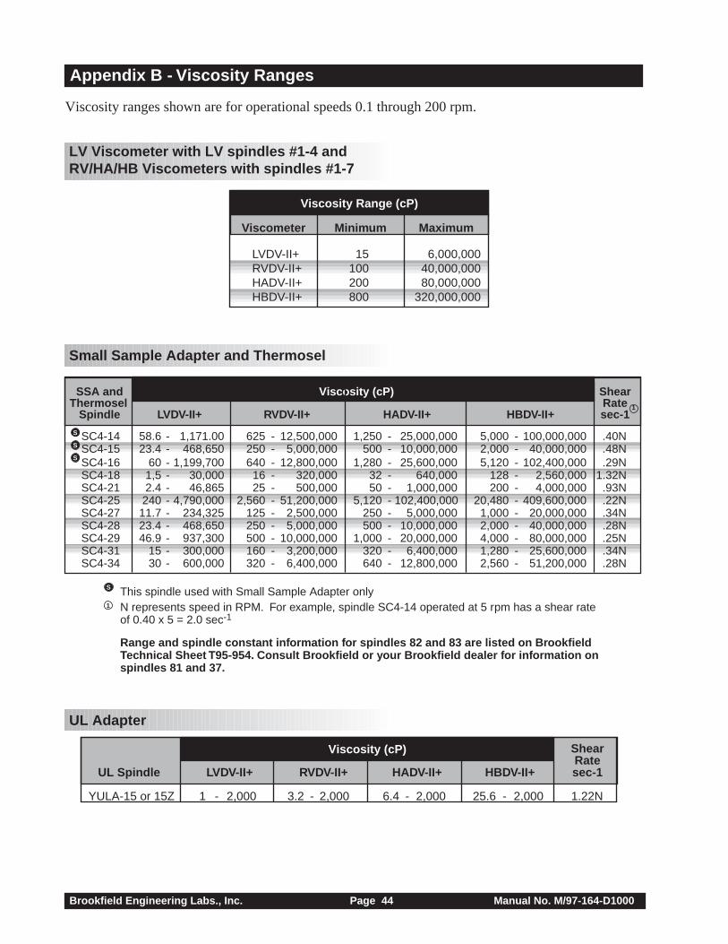
Brookfield Engineering Labs., Inc. Page 44 Manual No. M/97-164-D1000
Appendix B - Viscosity Ranges
Viscosity ranges shown are for operational speeds 0.1 through 200 rpm.
LV Viscometer with LV spindles #1-4 and RV/HA/HB Viscometers with spindles #1-7
Small Sample Adapter and Thermosel
UL Adapter
Viscometer Minimum Maximum
LVDV-II+ 15 6,000,000RVDV-II+ 100 40,000,000HADV-II+ 200 80,000,000HBDV-II+ 800 320,000,000
Viscosity Range (cP)
SSA and Viscosity (cP) ShearThermosel Rate
Spindle LVDV-II+ RVDV-II+ HADV-II+ HBDV-II+ sec-1
SC4-14 58.6 - 1,171.00 625 - 12,500,000 1,250 - 25,000,000 5,000 - 100,000,000 .40NSC4-15 23.4 - 468,650 250 - 5,000,000 500 - 10,000,000 2,000 - 40,000,000 .48NSC4-16 60 - 1,199,700 640 - 12,800,000 1,280 - 25,600,000 5,120 - 102,400,000 .29NSC4-18 1,5 - 30,000 16 - 320,000 32 - 640,000 128 - 2,560,000 1.32NSC4-21 2.4 - 46,865 25 - 500,000 50 - 1,000,000 200 - 4,000,000 .93NSC4-25 240 - 4,790,000 2,560 - 51,200,000 5,120 - 102,400,000 20,480 - 409,600,000 .22NSC4-27 11.7 - 234,325 125 - 2,500,000 250 - 5,000,000 1,000 - 20,000,000 .34NSC4-28 23.4 - 468,650 250 - 5,000,000 500 - 10,000,000 2,000 - 40,000,000 .28NSC4-29 46.9 - 937,300 500 - 10,000,000 1,000 - 20,000,000 4,000 - 80,000,000 .25NSC4-31 15 - 300,000 160 - 3,200,000 320 - 6,400,000 1,280 - 25,600,000 .34NSC4-34 30 - 600,000 320 - 6,400,000 640 - 12,800,000 2,560 - 51,200,000 .28N
S
S
S
S This spindle used with Small Sample Adapter onlyN represents speed in RPM. For example, spindle SC4-14 operated at 5 rpm has a shear rateof 0.40 x 5 = 2.0 sec-1
Range and spindle constant information for spindles 82 and 83 are listed on BrookfieldTechnical Sheet T95-954. Consult Brookfield or your Brookfield dealer for information onspindles 81 and 37.
1
1
ShearRate
UL Spindle LVDV-II+ RVDV-II+ HADV-II+ HBDV-II+ sec-1
YULA-15 or 15Z 1 - 2,000 3.2 - 2,000 6.4 - 2,000 25.6 - 2,000 1.22N
Viscosity (cP)
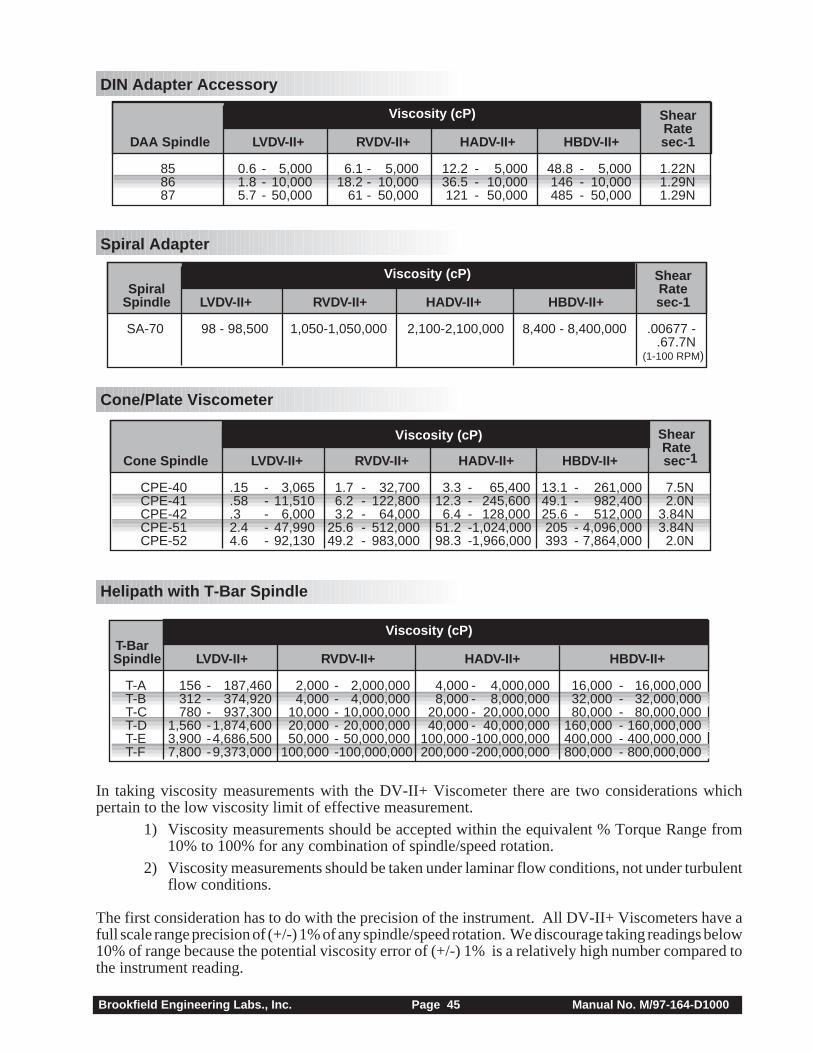
Brookfield Engineering Labs., Inc. Page 45 Manual No. M/97-164-D1000
DIN Adapter Accessory
Spiral Adapter
Cone/Plate Viscometer
Helipath with T-Bar Spindle
In taking viscosity measurements with the DV-II+ Viscometer there are two considerations whichpertain to the low viscosity limit of effective measurement.
1) Viscosity measurements should be accepted within the equivalent % Torque Range from10% to 100% for any combination of spindle/speed rotation.
2) Viscosity measurements should be taken under laminar flow conditions, not under turbulentflow conditions.
The first consideration has to do with the precision of the instrument. All DV-II+ Viscometers have afull scale range precision of (+/-) 1% of any spindle/speed rotation. We discourage taking readings below10% of range because the potential viscosity error of (+/-) 1% is a relatively high number compared tothe instrument reading.
ShearRate
DAA Spindle LVDV-II+ RVDV-II+ HADV-II+ HBDV-II+ sec-1
85 0.6 - 5,000 6.1 - 5,000 12.2 - 5,000 48.8 - 5,000 1.22N86 1.8 - 10,000 18.2 - 10,000 36.5 - 10,000 146 - 10,000 1.29N87 5.7 - 50,000 61 - 50,000 121 - 50,000 485 - 50,000 1.29N
Viscosity (cP)
ShearSpiral Rate
Spindle LVDV-II+ RVDV-II+ HADV-II+ HBDV-II+ sec-1
SA-70 98 - 98,500 1,050-1,050,000 2,100-2,100,000 8,400 - 8,400,000 .00677 -.67.7N
(1-100 RPM)
Viscosity (cP)
Viscosity (cP) ShearRate
Cone Spindle LVDV-II+ RVDV-II+ HADV-II+ HBDV-II+ sec -1
CPE-40 .15 - 3,065 1.7 - 32,700 3.3 - 65,400 13.1 - 261,000 7.5NCPE-41 .58 - 11,510 6.2 - 122,800 12.3 - 245,600 49.1 - 982,400 2.0NCPE-42 .3 - 6,000 3.2 - 64,000 6.4 - 128,000 25.6 - 512,000 3.84NCPE-51 2.4 - 47,990 25.6 - 512,000 51.2 -1,024,000 205 - 4,096,000 3.84NCPE-52 4.6 - 92,130 49.2 - 983,000 98.3 -1,966,000 393 - 7,864,000 2.0N
Viscosity (cP) T-Bar Spindle LVDV-II+ RVDV-II+ HADV-II+ HBDV-II+
T-A 156 - 187,460 2,000 - 2,000,000 4,000 - 4,000,000 16,000 - 16,000,000T-B 312 - 374,920 4,000 - 4,000,000 8,000 - 8,000,000 32,000 - 32,000,000T-C 780 - 937,300 10,000 - 10,000,000 20,000 - 20,000,000 80,000 - 80,000,000T-D 1,560 -1,874,600 20,000 - 20,000,000 40,000 - 40,000,000 160,000 - 160,000,000T-E 3,900 -4,686,500 50,000 - 50,000,000 100,000 -100,000,000 400,000 - 400,000,000T-F 7,800 -9,373,000 100,000 -100,000,000 200,000 -200,000,000 800,000 - 800,000,000
Brookfield Engineering Labs., Inc. Page 46 Manual No. M/97-164-D1000
The second consideration involves the mechanics of fluid flow. All rheological measurements of fluidflow properties should be made under laminar flow conditions. Laminar flow is flow wherein all particlemovement is in layers directed by the shearing force. For rotational systems, this means all fluidmovement must be circumferential. When the inertial forces on the fluid become too great, the fluid canbreak into turbulent flow wherein the movement of fluid particles becomes random and the flow can notbe analyzed with standard math models. This turbulence creates a falsely high Viscometer reading withthe degree of non-linear increase in reading being directly related to the degree of turbulence in the fluid.
For the following geometries, we have found that an approximate transition point to turbulent flowoccurs:
1) No. 1 LV Spindle: 15 cP at 60 RPM2) No. 1 RV Spindle: 100 cP at 50 RPM3) UL Adapter: 0.85 cP at 60 RPM
Turbulent conditions will exist in these situations whenever the RPM/cP ratio exceeds the values listedabove.
Brookfield Engineering Labs., Inc. Page 47 Manual No. M/97-164-D1000
Appendix C - Variables in Viscosity Measurements
As with any instrument measurement, there are variables that can affect a Viscometer measurement.These variables may be related to the instrument (Viscometer), or the test fluid. Variables related to thetest fluid deal with the rheological properties of the fluid, while instrument variables would include theViscometer design and the spindle geometry system utilized.
Rheological Properties
Fluids have different rheological characteristics that can be described by Viscometer measurements. Wecan then work with these fluids to suit our lab or process conditions.
There are two categories of fluids:
Newtonian - These fluids have the same viscosity at different Shear Rates (differentRPMs) and are called Newtonian over the Shear Rate range they aremeasured.
Non-Newtonian - These fluids have different viscosities at different shear rates (differentRPMs). They fall into two groups:
1) Time Independent non-Newtonian2) Time Dependent non-Newtonian
The time dependency is the time they are held at a given Shear Rate (RPM). They are non-Newtonian,and when you change the Viscometer spindle speed, you get a different viscosity.
Time Independent
Pseudoplastic - A pseudoplastic material displays a decrease in viscosity with an increase inshear rate, and is also known as “shear thinning”. If you take Viscometerreadings from a low to a high RPM and then back to the low RPM, and thereadings fall upon themselves, the material is time independent pseudoplasticand shear thinning.
Time Dependent
Thixotropic - A thixotropic material has decreasing viscosity under constant shear rate. Ifyou set a Viscometer at a constant speed recording cP values over time andfind that the cP values decrease with time, the material is thixotropic.
Brookfield publication, “More Solutions to Sticky Problems” includes a more detailed discussion ofrheological properties and non-Newtonian behavior.
Viscometer Related Variables
Most fluid viscosities are found to be non-Newtonian. They are dependent on Shear Rate and the spindlegeometry conditions. The specifications of the Viscometer spindle and chamber geometry will affectthe viscosity readings. If one reading is taken at 2.5 rpm, and a second at 50 rpm, the two cP valuesproduced will be different because the readings were made at different shear rates. The faster the spindlespeed, the higher the shear rate.
The shear rate of a given measurement is determined by: the rotational speed of the spindle, the size andshape of the spindle, the size and shape of the container used and therefore the distance between the
Brookfield Engineering Labs., Inc. Page 48 Manual No. M/97-164-D1000
container wall and the spindle surface.
A repeatable viscosity test should control or specify the following:
1) Test temperature2) Sample container size (or spindle/chamber geometry)3) Sample volume4) Viscometer model5) Spindle used (if using LVDV-II+ (#1-4) or RVDV-II+ (#1-7) attach the guard leg)6) Test speed or speeds (or the shear rate)7) Length of time or number of spindle revolutions to record viscosity.
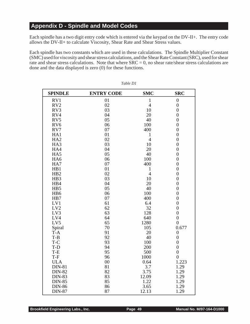
Brookfield Engineering Labs., Inc. Page 49 Manual No. M/97-164-D1000
Appendix D - Spindle and Model Codes
Each spindle has a two digit entry code which is entered via the keypad on the DV-II+. The entry codeallows the DV-II+ to calculate Viscosity, Shear Rate and Shear Stress values.
Each spindle has two constants which are used in these calculations. The Spindle Multiplier Constant(SMC) used for viscosity and shear stress calculations, and the Shear Rate Constant (SRC), used for shearrate and shear stress calculations. Note that where SRC = 0, no shear rate/shear stress calculations aredone and the data displayed is zero (0) for these functions.
Table D1
RV1 01 1 0RV2 02 4 0RV3 03 10 0RV4 04 20 0RV5 05 40 0RV6 06 100 0RV7 07 400 0HA1 01 1 0HA2 02 4 0HA3 03 10 0HA4 04 20 0HA5 05 40 0HA6 06 100 0HA7 07 400 0HB1 01 1 0HB2 02 4 0HB3 03 10 0HB4 04 20 0HB5 05 40 0HB6 06 100 0HB7 07 400 0LV1 61 6.4 0LV2 62 32 0LV3 63 128 0LV4 64 640 0LV5 65 1280 0Spiral 70 105 0.677T-A 91 20 0T-B 92 40 0T-C 93 100 0T-D 94 200 0T-E 95 500 0T-F 96 1000 0ULA 00 0.64 1.223DIN-81 81 3.7 1.29DIN-82 82 3.75 1.29DIN-83 83 12.09 1.29DIN-85 85 1.22 1.29DIN-86 86 3.65 1.29DIN-87 87 12.13 1.29
SPINDLE ENTRY CODE SMC SRC
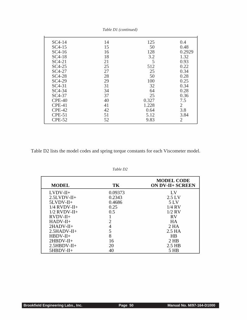
Brookfield Engineering Labs., Inc. Page 50 Manual No. M/97-164-D1000
SC4-14 14 125 0.4SC4-15 15 50 0.48SC4-16 16 128 0.2929SC4-18 18 3.2 1.32SC4-21 21 5 0.93SC4-25 25 512 0.22SC4-27 27 25 0.34SC4-28 28 50 0.28SC4-29 29 100 0.25SC4-31 31 32 0.34SC4-34 34 64 0.28SC4-37 37 25 0.36CPE-40 40 0.327 7.5CPE-41 41 1.228 2CPE-42 42 0.64 3.8CPE-51 51 5.12 3.84CPE-52 52 9.83 2
Table D2 lists the model codes and spring torque constants for each Viscometer model.
Table D1 (continued)
Table D2
LVDV-II+ 0.09373 LV2.5LVDV-II+ 0.2343 2.5 LV5LVDV-II+ 0.4686 5 LV1/4 RVDV-II+ 0.25 1/4 RV1/2 RVDV-II+ 0.5 1/2 RVRVDV-II+ 1 RVHADV-II+ 2 HA2HADV-II+ 4 2 HA2.5HADV-II+ 5 2.5 HAHBDV-II+ 8 HB2HBDV-II+ 16 2 HB2.5HBDV-II+ 20 2.5 HB5HBDV-II+ 40 5 HB
MODEL TKMODEL CODE
ON DV-II+ SCREEN
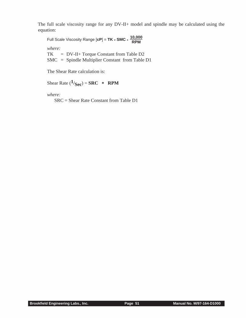
Brookfield Engineering Labs., Inc. Page 51 Manual No. M/97-164-D1000
The full scale viscosity range for any DV-II+ model and spindle may be calculated using theequation:
Full Scale Viscosity Range [cP] = TK * SMC *10,000RPM
where:TK = DV-II+ Torque Constant from Table D2SMC = Spindle Multiplier Constant from Table D1
The Shear Rate calculation is:
Shear Rate (1/Sec) = SRC * RPM
where:SRC = Shear Rate Constant from Table D1
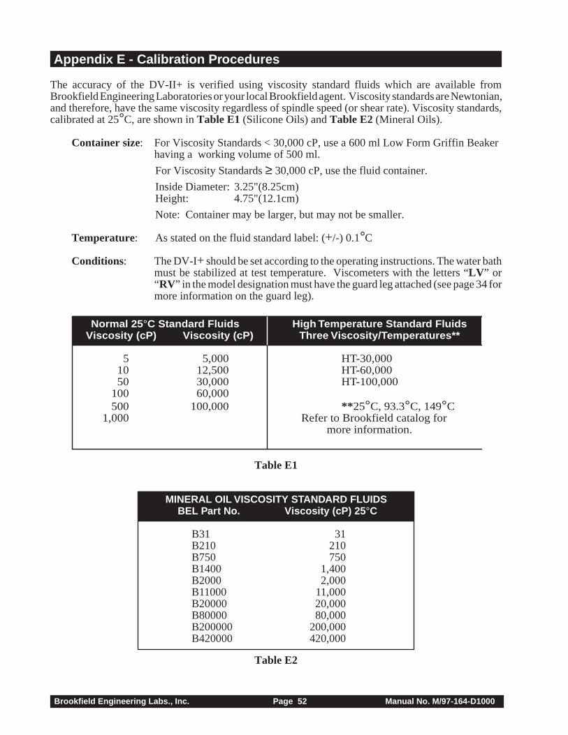
Brookfield Engineering Labs., Inc. Page 52 Manual No. M/97-164-D1000
Appendix E - Calibration Procedures
The accuracy of the DV-II+ is verified using viscosity standard fluids which are available fromBrookfield Engineering Laboratories or your local Brookfield agent. Viscosity standards are Newtonian,and therefore, have the same viscosity regardless of spindle speed (or shear rate). Viscosity standards,calibrated at 25°C, are shown in Table E1 (Silicone Oils) and Table E2 (Mineral Oils).
Container size: For Viscosity Standards < 30,000 cP, use a 600 ml Low Form Griffin Beakerhaving a working volume of 500 ml.
For Viscosity Standards ≥ 30,000 cP, use the fluid container.
Inside Diameter: 3.25"(8.25cm)Height: 4.75"(12.1cm)
Note: Container may be larger, but may not be smaller.
Temperature: As stated on the fluid standard label: (+/-) 0.1°C
Conditions: The DV-I+ should be set according to the operating instructions. The water bathmust be stabilized at test temperature. Viscometers with the letters “LV ” or“RV” in the model designation must have the guard leg attached (see page 34 formore information on the guard leg).
Normal 25 °C Standard Fluids High Temperature Standard FluidsViscosity (cP) Viscosity (cP) Three Viscosity/Temperatures**
5 5,000 HT-30,00010 12,500 HT-60,00050 30,000 HT-100,000
100 60,000500 100,000 ** 25°C, 93.3°C, 149°C
1,000 Refer to Brookfield catalog formore information.
Table E1
MINERAL OIL VISCOSITY STANDARD FLUIDSBEL Part No. Viscosity (cP) 25 °C
B31 31B210 210B750 750B1400 1,400B2000 2,000B11000 11,000B20000 20,000B80000 80,000B200000 200,000B420000 420,000
Table E2
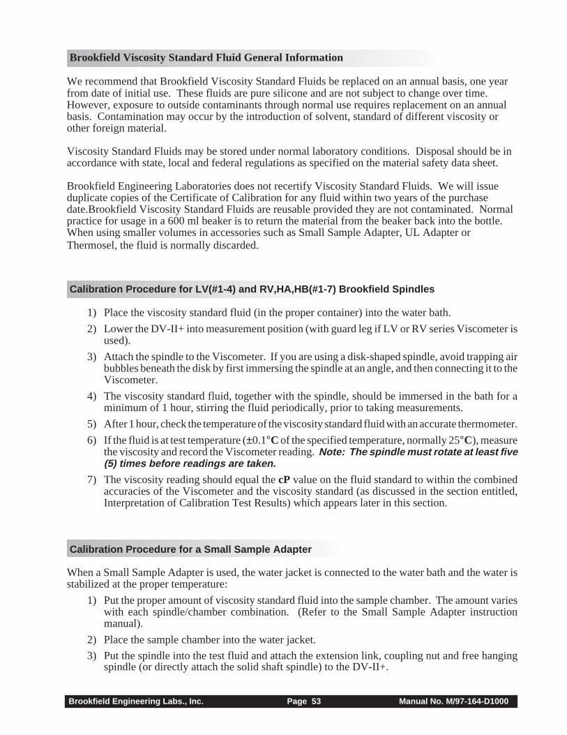
Brookfield Engineering Labs., Inc. Page 53 Manual No. M/97-164-D1000
Brookfield Viscosity Standard Fluid General Information
We recommend that Brookfield Viscosity Standard Fluids be replaced on an annual basis, one yearfrom date of initial use. These fluids are pure silicone and are not subject to change over time.However, exposure to outside contaminants through normal use requires replacement on an annualbasis. Contamination may occur by the introduction of solvent, standard of different viscosity orother foreign material.
Viscosity Standard Fluids may be stored under normal laboratory conditions. Disposal should be inaccordance with state, local and federal regulations as specified on the material safety data sheet.
Brookfield Engineering Laboratories does not recertify Viscosity Standard Fluids. We will issueduplicate copies of the Certificate of Calibration for any fluid within two years of the purchasedate.Brookfield Viscosity Standard Fluids are reusable provided they are not contaminated. Normalpractice for usage in a 600 ml beaker is to return the material from the beaker back into the bottle.When using smaller volumes in accessories such as Small Sample Adapter, UL Adapter orThermosel, the fluid is normally discarded.
Calibration Procedure for LV(#1-4) and RV,HA,HB(#1-7) Brookfield Spindles
1) Place the viscosity standard fluid (in the proper container) into the water bath.
2) Lower the DV-II+ into measurement position (with guard leg if LV or RV series Viscometer isused).
3) Attach the spindle to the Viscometer. If you are using a disk-shaped spindle, avoid trapping airbubbles beneath the disk by first immersing the spindle at an angle, and then connecting it to theViscometer.
4) The viscosity standard fluid, together with the spindle, should be immersed in the bath for aminimum of 1 hour, stirring the fluid periodically, prior to taking measurements.
5) After 1 hour, check the temperature of the viscosity standard fluid with an accurate thermometer.
6) If the fluid is at test temperature (±0.1°C of the specified temperature, normally 25°C), measurethe viscosity and record the Viscometer reading. Note: The spindle must rotate at least five(5) times before readings are taken.
7) The viscosity reading should equal the cP value on the fluid standard to within the combinedaccuracies of the Viscometer and the viscosity standard (as discussed in the section entitled,Interpretation of Calibration Test Results) which appears later in this section.
Calibration Procedure for a Small Sample Adapter
When a Small Sample Adapter is used, the water jacket is connected to the water bath and the water isstabilized at the proper temperature:
1) Put the proper amount of viscosity standard fluid into the sample chamber. The amount varieswith each spindle/chamber combination. (Refer to the Small Sample Adapter instructionmanual).
2) Place the sample chamber into the water jacket.
3) Put the spindle into the test fluid and attach the extension link, coupling nut and free hangingspindle (or directly attach the solid shaft spindle) to the DV-II+.
Brookfield Engineering Labs., Inc. Page 54 Manual No. M/97-164-D1000
4) Allow 30 minutes for the viscosity standard, sample chamber and spindle to reach testtemperature.
5) Measure the viscosity and record the Viscometer reading. Note: The spindle must rotate atleast five (5) times before readings are taken.
Calibration Procedure for a Thermosel System
When a Thermosel System is used, the controller stabilizes the Thermo Container at the test temperature.
1) Put the proper amount of HT viscosity standard fluid into the HT-2 sample chamber. Theamount varies with the spindle used. (Refer to the Thermosel instruction manual).
2) Place the sample chamber into the Thermo Container.
3) Put the spindle into the test fluid and attach the extension link, coupling nut and free hangingspindle (or directly attach the solid shaft spindle) to the DV-II+.
4) Allow 30 minutes for the viscosity standard, sample chamber and spindle to reach testtemperature.
5) Measure the viscosity and record the Viscometer reading. Note: The spindle must rotate atleast five (5) times before readings are taken.
Calibration Procedure using UL or DIN UL Adapters
When a UL or DIN UL Adapter is used, the water bath is stabilized at the proper temperature:
1) Put the proper amount of viscosity standard fluid into the UL Tube. (Refer to the UL Adapterinstruction manual).
2) Attach the spindle (with extension link and coupling nut) onto the DV-II+.
3) Attach the tube to the mounting channel.
4) Lower the tube into the water bath reservoir, or if using the ULA-40Y water jacket, connect theinlet/outlets to the bath external circulating pump.
5) Allow 30 minutes for the viscosity standard, sample chamber and spindle to reach testtemperature.
6) Measure the viscosity and record the Viscometer reading. Note: The spindle must rotate atleast five (5) times before readings are taken.
Calibration Procedure using a Helipath Stand and T-Bar Spindles
When a Helipath Stand and T-Bar spindles are used:
1) Remove the T-bar spindle and select a standard LV(#1-4) or RV,HA,HB(#1-7) spindle. Followthe procedures for LV(#1-4) and RV,HA,HB(#1-7) Brookfield spindles outlined above.
2) T-Bar spindles should not be used for verifying calibration of the DV-II+ Viscometer.
Calibration Procedure for Spiral Adapter
1) Place the viscosity standard fluid (in the proper container) into the water bath.
2) Attach the spindle to the viscometer. Attach chamber (SA-1Y) and clamp to the viscometer.
3) Lower the DV-II+ into measurement position. Operate the viscometer at 50 or 60 RPM untilthe chamber is fully flooded.
Brookfield Engineering Labs., Inc. Page 55 Manual No. M/97-164-D1000
4) The viscosity standard fluid, together with the spindle, should be immersed in the bath for aminimum of 1 hour, stirring the fluid periodically (operate at 50 or 60 RPM periodically), priorto taking measurements.
5) After 1 hour, check the temperature of the viscosity standard fluid with an accurate thermometer.
6) If the fluid is at test temperature (+/- 0.1°C of the specified temperature, normally 25°C),measure the viscosity and record the viscometer reading. Note: The spindle must rotateat least five (5) times for one minute, whichever is greater before readings are taken.
7) The viscosity reading should equal the cP value on the viscosity fluid standard to within thecombined accuracies of the viscometer and the standard (as discussed in the section entitled,Interpretation of Calibration Test Results).
Calibration Procedure for Cone/Plate Viscometers:
1) Follow the above procedures for mechanically adjusting the setting of the cone spindle to theplate.
2) Refer to Appendix A, Table A1, and determine the correct sample volume required for theselected spindle.
3) Select a viscosity standard fluid that will give viscosity readings between 10% and 100% of fullscale range. Refer to Appendix B for viscosity ranges of cone spindles. Consult with Brookfieldor an authorized dealer to determine which fluid is appropriate.
It is best to use a viscosity standard fluid that will be close to the maximum viscosity for a givencone spindle/speed combination.
Example: LVDV-II + Viscometer, Cone CP-42, Fluid 10Having a viscosity of 9.7 cP at 25°C
At 60 RPM, the full scale viscosity range is 10.0 cP. Thus, the Viscometer reading should be97% torque and 9.7 cP viscosity ± 0.197 cP (0.1 cP for the viscometer plus 0.97 cP for the fluid).The accuracy is a combination of Viscometer and fluid tolerance (refer to Interpretation ofCalibration Test Results).
4) With the viscometer stopped, remove the sample cup and place the viscosity standard fluid intothe cup, waiting 10 minutes for temperature equilibrium.
5) Connect the sample cup to the Viscometer. Allow sufficient time for temperature to reachequilibrium. Typically 15 minutes is the maximum time that you must wait. Less time is requiredif spindle and cup are already at test temperature.
6) Measure the viscosity and record the Viscometer reading in both % torque and centipoise (cP).
Notes: 1) The spindle must rotate at least five (5) times before a viscosity reading is taken.
2) The use of Brookfield Viscosity Standard fluids in the range of 5 cP to 5000 cPis recommended for cone/plate instruments. Please contact Brookfield Engineer-ing Laboratories or an authorized dealer if your calibration procedure requiresmore viscous standards.
3) Select a viscosity standard fluid that will give viscosity readings between 10% and100% of full scale range. Refer to Appendix B for viscosity ranges of conespindles. Do not use a silicone viscosity standard fluid with a viscosity valuegreater than 5000 cP with a Cone/Plate Viscometer. Brookfield offers a completerange of mineral oil viscosity standards suitable for use with Cone/Plate Viscom-eters as shown in Table E2. Consult with Brookfield or an authorized dealer todetermine which fluid is appropriate.
Brookfield Engineering Labs., Inc. Page 56 Manual No. M/97-164-D1000
Interpretation of Calibration Test Results:
When verifying the calibration of the DV-II+, the instrument and viscosity standard fluid error must becombined to calculate the total allowable error.
The DV-II+ is accurate to (+/-) 1% of any full scale spindle/speed viscosity range.
Brookfield Viscosity Standards Fluids are accurate to (+/-) 1% of their stated value.
Example: Calculate the acceptable range of viscosity using RVDV-II+ with RV-3 Spindleat 2 RPM; Brookfield Standard Fluid 12,500 with a viscosity of 12,257 cP at 25°C:
1) Calculate full scale viscosity range using the equation:
Full Scale Viscosity Range [cP] = TK * SMC *10,000RPM
Where:TK = 1.0 from Table D2SMC = 10 from Table D1
Full Scale Viscosity Range = 50,000 cP1 * 10 * 10,0002
The viscosity is accurate to (+/-) 500 cP (which is 1% of 50,000)
2) The viscosity standard fluid is 12,257 cP. Its accuracy is (+/-)1% of 12,257 or(+/-)122.57 cP.
3) Total allowable error is (122.57 + 500) cP = (+/-) 622.57 cP.
4) Therefore, any viscosity reading between 11,634.4 and 12,879.6 cP indicates that the Viscom-eter is operating correctly. Any reading outside these limits may indicate a Viscometer problem.Contact the Brookfield technical sales department or your local Brookfield dealer/distributorwith test results to determine the nature of the problem.
The Brookfield Guardleg
The guard leg was originally designed to protect the spindle during use. The first applications of theBrookfield Viscometer included hand held operation while measuring fluids in a 55-gallon drum. It isclear that under those conditions the potential for damage to the spindle was great. Original constructionincluded a sleeve that protected the spindle from side impact. Early RV guard legs attached to the dialhousing and LV guard legs attached to the bottom of the pivot cup with a twist and lock mechanism.
The current guard leg is a band of metal in the shape of the letter U with a bracket at the top that attachesto the pivot cup of a Brookfield Viscometer/Rheometer. Because it must attach to the pivot cup, the guardleg cannot be used with a Cone/Plate instrument. A guard leg is supplied with all LV and RV seriesinstruments, but not with the HA or HB series. It’s shape (shown in Figure 1) is designed toaccommodate the spindles of the appropriate spindle set; therefore, the RV guard leg is wider than theLV due to the large diameter of the RV #1 spindle. They are not interchangeable.
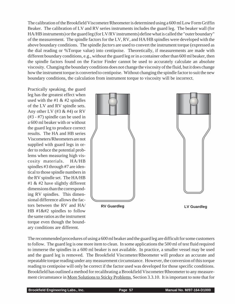
Brookfield Engineering Labs., Inc. Page 57 Manual No. M/97-164-D1000
The calibration of the Brookfield Viscometer/Rheometer is determined using a 600 ml Low Form GriffinBeaker. The calibration of LV and RV series instruments includes the guard leg. The beaker wall (forHA/HB instruments) or the guard leg (for LV/RV instruments) define what is called the "outer boundary"of the measurement. The spindle factors for the LV, RV, and HA/HB spindles were developed with theabove boundary conditions. The spindle factors are used to convert the instrument torque (expressed asthe dial reading or %Torque value) into centipoise. Theoretically, if measurements are made withdifferent boundary conditions, e.g., without the guard leg or in a container other than 600 ml beaker, thenthe spindle factors found on the Factor Finder cannot be used to accurately calculate an absoluteviscosity. Changing the boundary conditions does not change the viscosity of the fluid, but it does changehow the instrument torque is converted to centipoise. Without changing the spindle factor to suit the newboundary conditions, the calculation from instrument torque to viscosity will be incorrect.
Practically speaking, the guardleg has the greatest effect whenused with the #1 & #2 spindlesof the LV and RV spindle sets.Any other LV (#3 & #4) or RV(#3 - #7) spindle can be used ina 600 ml beaker with or withoutthe guard leg to produce correctresults. The HA and HB seriesViscometers/Rheometers are notsupplied with guard legs in or-der to reduce the potential prob-lems when measuring high vis-cosity materials. HA/HBspindles #3 through #7 are iden-tical to those spindle numbers inthe RV spindle set. The HA/HB#1 & #2 have slightly differentdimensions than the correspond-ing RV spindles. This dimen-sional difference allows the fac-tors between the RV and HA/HB #1 spindles to followthe same ratios as the instrumenttorque even though the bound-ary conditions are different.
The recommended procedures of using a 600 ml beaker and the guard leg are difficult for some customersto follow. The guard leg is one more item to clean. In some applications the 500 ml of test fluid requiredto immerse the spindles in a 600 ml beaker is not available. In practice, a smaller vessel may be usedand the guard leg is removed. The Brookfield Viscometer/Rheometer will produce an accurate andrepeatable torque reading under any measurement circumstance. However, the conversion of this torquereading to centipoise will only be correct if the factor used was developed for those specific conditions.Brookfield has outlined a method for recalibrating a Brookfield Viscometer/Rheometer to any measure-ment circumstance in More Solutions to Sticky Problems, Section 3.3.10. It is important to note that for
RV Guardleg LV Guardleg
Brookfield Engineering Labs., Inc. Page 58 Manual No. M/97-164-D1000
many viscometer users the true viscosity is not as important as a repeatable day to day value. Thisrepeatable value can be obtained without any special effort for any measurement circumstance. But, itshould be known that this type of torque reading will not convert into a correct centipoise value whenusing a Brookfield factor if the boundary conditions are not those specified by Brookfield.
The guard leg is a part of the calibration check of the Brookfield LV and RV series Viscometer/Rheometer. Our customers should be aware of its existence, its purpose and the effect that it may haveon data. With this knowledge, the viscometer user may make modifications to the recommended methodof operation to suit their needs.
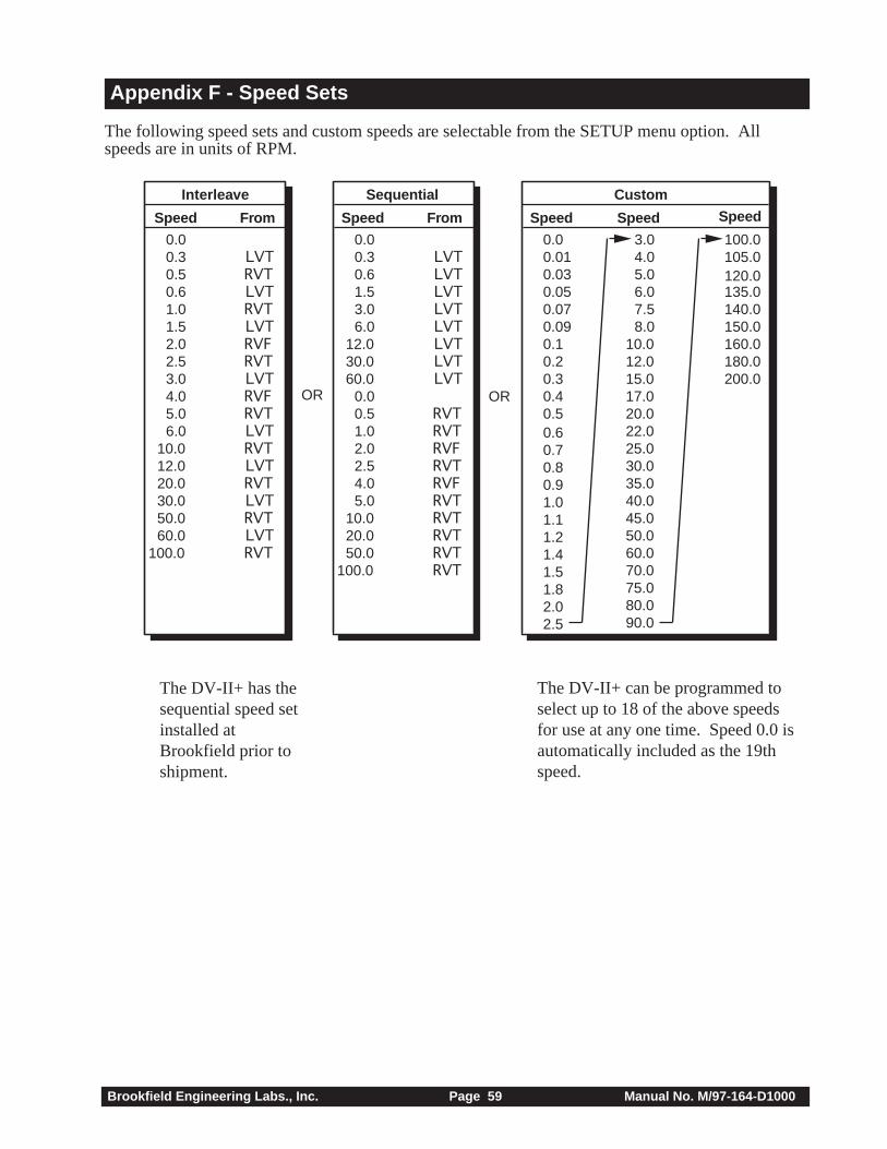
Brookfield Engineering Labs., Inc. Page 59 Manual No. M/97-164-D1000
Appendix F - Speed Sets
The following speed sets and custom speeds are selectable from the SETUP menu option. Allspeeds are in units of RPM.
The DV-II+ has thesequential speed setinstalled atBrookfield prior toshipment.
The DV-II+ can be programmed toselect up to 18 of the above speedsfor use at any one time. Speed 0.0 isautomatically included as the 19thspeed.
Custom
SpeedSpeedSpeed
7.58.0
15.017.0
5.06.0
10.012.0
20.022.025.0
35.040.045.0
70.075.080.0
30.0
50.060.0
105.0120.0
150.0
135.0140.0
160.0180.0200.0
100.0
90.0
3.04.0
0.0
0.1
0.6
0.80.9
1.5
0.20.30.40.5
0.7
1.11.2
1.0
1.82.0
1.4
0.010.030.050.070.09
2.5
OR
Sequential
Speed From
LVTLVTLVTLVTLVTLVTLVTLVT
RVTRVT
RVT
RVT
RVT
RVT
RVT
RVT
RVF
RVF
0.00.3
0.5
0.6
1.0
1.5
2.02.5
3.0
4.0
0.0
5.0
6.0
10.0
12.0
20.0
30.0
50.0
60.0
100.0100.0
LVT
LVT
LVT
LVT
LVT
LVT
LVT
LVT
RVT
RVT
RVFRVT
RVT
RVT
RVT
RVT
RVT
0.00.30.50.61.01.52.02.53.04.05.06.0
10.012.020.030.050.060.0
RVF
Interleave
FromSpeed
OR

Brookfield Engineering Labs., Inc. Page 60 Manual No. M/97-164-D1000
Appendix G - Communications
When using the Brookfield Computer Cable (Brookfield part # DVP-80), the DV-II+ will output adata string at a rate of approximately 3 times per second. When using the Brookfield Printer Cable(Brookfield Part No. DVP-81), the output rate is 1.0 times per second. The DV-II+ uses the follow-ing RS-232 parameters to output these strings:
Baud Rate 9600Data Bits 8Stop Bits 1Parity NoneHandshake None
The following formulas should be used to calculate and display the Viscometer data after eachpacket of data is obtained from the DV-II+.
Viscosity (cP) = 100 * TK * SMC * TorqueRPM
Shear Rate (1/Sec) = RPM * SRC
Shear Stress (Dynes/Cm2) = TK * SMC * SRC * Torque
Where:RPM = Current Viscometer spindle speed in RPMTK = Viscometer torque constant from Appendix D, Table D2.SMC = Current spindle multiplier constant from Appendix D, Table D1.SRC = Current spindle shear rate constant from Appendix D, Table D1.Torque = Current Viscometer torque (%) expressed as a number between 0 and 100.
As an example, consider an LV Viscometer using an SC4-31 spindle, running at 30 RPM and cur-rently displaying a Torque of 62.3 (%). First we list all of the given data and include model andspindle constants from Appendix D, Tables D1 and D2:
RPM = 30 from the example statement.TK = 0.09373 from Appendix D for an LV Viscometer.SMC = 32.0 from Appendix D for a type SC4-31 spindle.SRC = 0.34 from Appendix D for a type SC4-31 spindle.Torque = 62.3 from the example statement.
Applying this data to the above equations yields:
Viscosity (cP) = 100 * TK * SMC * TorqueRPM
= 100 * 0.09373 * 32.0 * 62.3 30
= 622.9 cP
Shear Rate (1/Sec) = RPM * SRC
= 30 * 0.34
= 10.2 1/Sec
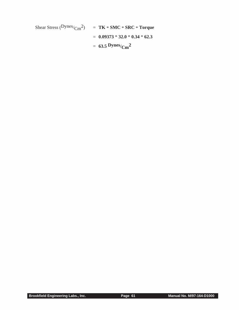
Brookfield Engineering Labs., Inc. Page 61 Manual No. M/97-164-D1000
Shear Stress (Dynes/Cm2) = TK * SMC * SRC * Torque
= 0.09373 * 32.0 * 0.34 * 62.3
= 63.5 Dynes/Cm2
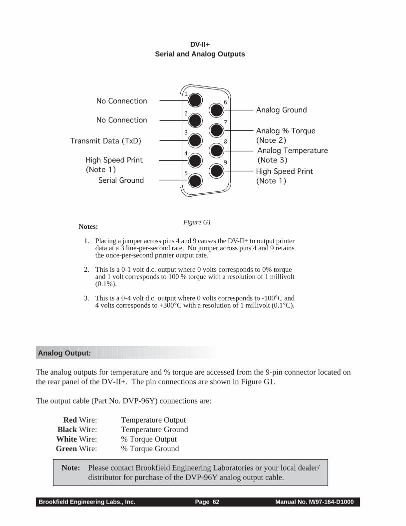
Brookfield Engineering Labs., Inc. Page 62 Manual No. M/97-164-D1000
Figure G1
Analog Output:
The analog outputs for temperature and % torque are accessed from the 9-pin connector located onthe rear panel of the DV-II+. The pin connections are shown in Figure G1.
The output cable (Part No. DVP-96Y) connections are:
Red Wire: Temperature OutputBlack Wire: Temperature GroundWhite Wire: % Torque OutputGreen Wire: % Torque Ground
Note: Please contact Brookfield Engineering Laboratories or your local dealer/distributor for purchase of the DVP-96Y analog output cable.
2
3
4
5
6
7
8
9
1No Connection
Transmit Data (TxD)
No Connection
High Speed Print(Note 1) High Speed Print
(Note 1)Serial Ground
Analog Ground
Analog % Torque(Note 2)Analog Temperature(Note 3)
DV-II+Serial and Analog Outputs
Notes:
1. Placing a jumper across pins 4 and 9 causes the DV-II+ to output printerdata at a 3 line-per-second rate. No jumper across pins 4 and 9 retainsthe once-per-second printer output rate.
2. This is a 0-1 volt d.c. output where 0 volts corresponds to 0% torqueand 1 volt corresponds to 100 % torque with a resolution of 1 millivolt(0.1%).
3. This is a 0-4 volt d.c. output where 0 volts corresponds to -100°C and4 volts corresponds to +300°C with a resolution of 1 millivolt (0.1°C).
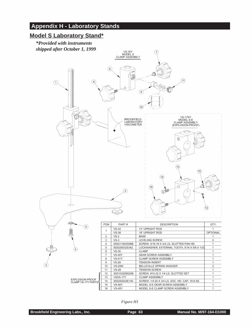
Brookfield Engineering Labs., Inc. Page 63 Manual No. M/97-164-D1000
Appendix H - Laboratory Stands
EXPLOSION-PROOFCLAMP VS-17Y PARTS
BROOKFIELDLABORATORYVISCOMETER
VS-35YMODEL S
CLAMP ASSEMBLY
2
3
4
5
1 8
6
7
9
10
11
ITEM PART #
10
9
8
7
6
5
4
3
2
1
2
1
1
1
1
1
1
2
1
OPTIONAL
QTY.
VS-29W
VS-29
VS-41Y
VS-40Y
VS-35
502020032S34Z
50S311824S06B
VS-3
VS-2
VS-34
VS-38
1
DESCRIPTION
BELLEVILLE SPRING WASHER
TENSION INSERT
CLAMP SCREW ASSEMBLY
GEAR SCREW ASSEMBLY
CLAMP
LOCKWASHER, EXTERNAL TOOTH, 5/16 X 5/8 X 1/32
SCREW, 5/16-18 X 3/4 LG. SLOTTED PAN HD.
LEVELING SCREW
BASE
14” UPRIGHT ROD
18” UPRIGHT ROD
12
11
13
1
1
1
50S103208S25B
VS-28
VSXA-17Y
SCREW, #10-32 X 1/4 LG. SLOTTED SET
TENSION SCREW
CLAMP ASSEMBLY
15
14
16
1
1
1
VS-46Y
50S252024E140
VS-45Y
MODEL S-E GEAR SCREW ASSEMBLY
SCREW, 1/4-20 X 3/4 LG. SOC. HD. CAP, 18-8 SS
MODEL S-E CLAMP SCREW ASSEMBLY
VS-17SYMODEL S-E
CLAMP ASSEMBLY(EXPLOSION-PROOF)
13
15
12
16
14
Figure H1
Model S Laborator y Stand**Provided with instrumentsshipped after October 1, 1999
Brookfield Engineering Labs., Inc. Page 64 Manual No. M/97-164-D1000
Unpacking
Check carefully to see that all the components are received with no concealed damage.
1 Base, VS-2, with 2 Leveling Screws, VS-3, packed in a cardboard carton1 Upright Rod, VS-34, with attached Clamp Assembly, VS-35Y
Assembly (Refer to Figure H1)
1. Remove the base assembly from the carton.2. Remove the screw and washer from the upright rod. Place the rod and clamp assembly into the hole
in the top of the base.Note: The “Front” designation on the clamp assembly should face the
opening of the legs, i.e., parallel to the leveling feet.3. Rotate the rod/clamp assembly slightly until the slot on the bottom of the rod intersects the pin
located in the base.4. While holding the rod and base together, insert the slotted screw and washer as shown and tighten
securely.
Viscometer Mounting
Insert the Viscometer mounting rod into the hole (with the cut-away slot) in the clamp assembly. Adjustthe instrument level until the bubble is centered from right to left and tighten the clamp knob(clockwise). Use the leveling screws to “fine” adjust the viscometer level. Note: If the DigitalViscometer cannot be leveled, check to insure that the rod is installed with the gear rack facingforward.
Note: If the clamp is taken off the upright rod, the tension insert (Part No. VS-29) must beproperly aligned for the clamp to fit back onto the upright rod. When the tensioninsert (Part No. VS-29) is inserted, its slot must be in the vertical position parallel tothe upright rod. If the slot is not in the correct position, the clamp will not slide downover the upright rod. Use a small screwdriver or pencil to move it into the correctposition. The VS-29W Belleville spring washers must face each other as illustrated.Adjust the VS-28 tension screw so that the clamp assembly is not loose on the uprightrod.
Caution: Do not tighten the clamp knob unless the viscometer mounting rod isinserted in the clamp assembly.
Center the Viscometer relative to the stand base and retighten the jam nut as required. Referring to theViscometer bubble level, adjust the leveling screws until the instrument is level.
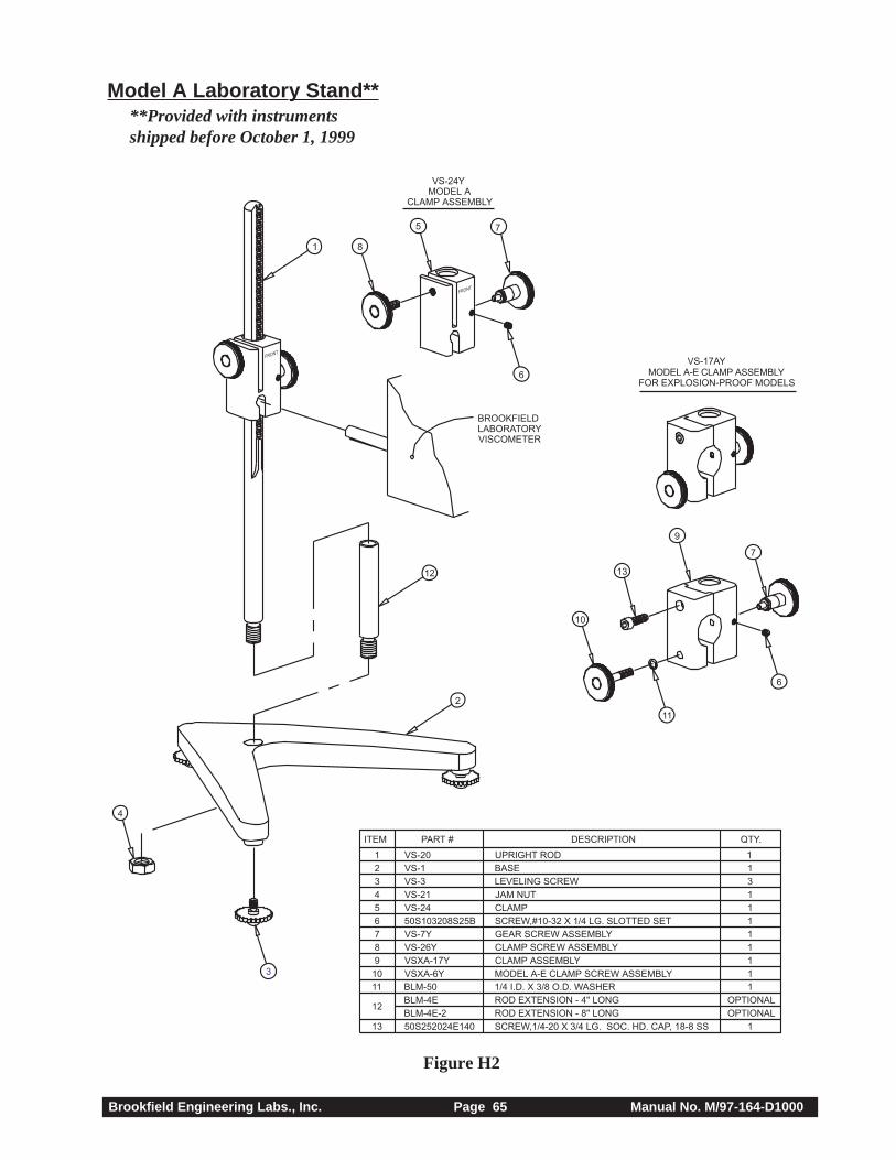
Brookfield Engineering Labs., Inc. Page 65 Manual No. M/97-164-D1000
Figure H2
Model A Laborator y Stand****Provided with instrumentsshipped before October 1, 1999
FRONT
FRONT
1 8
5 7
6
BROOKFIELDLABORATORYVISCOMETER
VS-17AYMODEL A-E CLAMP ASSEMBLY
VS-24YMODEL A
CLAMP ASSEMBLY
2
12
10
13
9
7
6
11
4
3
11
12
13
123456789
10
ITEM DESCRIPTION
MODEL A-E CLAMP SCREW ASSEMBLYCLAMP ASSEMBLYCLAMP SCREW ASSEMBLYGEAR SCREW ASSEMBLYSCREW,#10-32 X 1/4 LG. SLOTTED SETCLAMPJAM NUTLEVELING SCREWBASEUPRIGHT ROD
SCREW,1/4-20 X 3/4 LG. SOC. HD. CAP, 18-8 SSROD EXTENSION - 8" LONGROD EXTENSION - 4" LONG1/4 I.D. X 3/8 O.D. WASHER
PART #
VS-20VS-1VS-3VS-21VS-2450S103208S25BVS-7YVS-26YVSXA-17YVSXA-6YBLM-50BLM-4EBLM-4E-250S252024E140
QTY.
1OPTIONALOPTIONAL
11111111311
FOR EXPLOSION-PROOF MODELS

Brookfield Engineering Labs., Inc. Page 66 Manual No. M/97-164-D1000
Unpacking
Check carefully to see that all the components are received with no concealed damage.
1 base 1 jam nut3 leveling screws 1 clamp assembly1 upright rod
Remove the three (3) leveling screws from the base and discard the packing material. Remove the jamnut from the upright rod.
Assembly (Refer to Figure H2)
Screw the leveling screws into the base. Insert the threaded end of the upright rod into the hole in thetop of the base and attach the jam nut to the rod on the underside of the base. With the rod gear rack facingforward (toward the “V” in the base), gently tighten the jam nut.
Viscometer Mounting
Insert the Viscometer mounting rod into the hole (with the cut-away slot) in the clamp assembly. Adjustthe instrument level until the bubble is centered from right to left and tighten the Clamp Screw(clockwise).
Note: The small clamp adjusting screw (Figure H1) on the clamp assembly should beloosened or tightened as necessary to provide smooth height adjustment andadequate support for the Viscometer.
Center the Viscometer relative to the stand base and retighten the jam nut as required. Referring to theViscometer bubble level, adjust the leveling screws until the instrument is level.
Operation
Rotate the Gear Screw to raise or lower the viscometer.
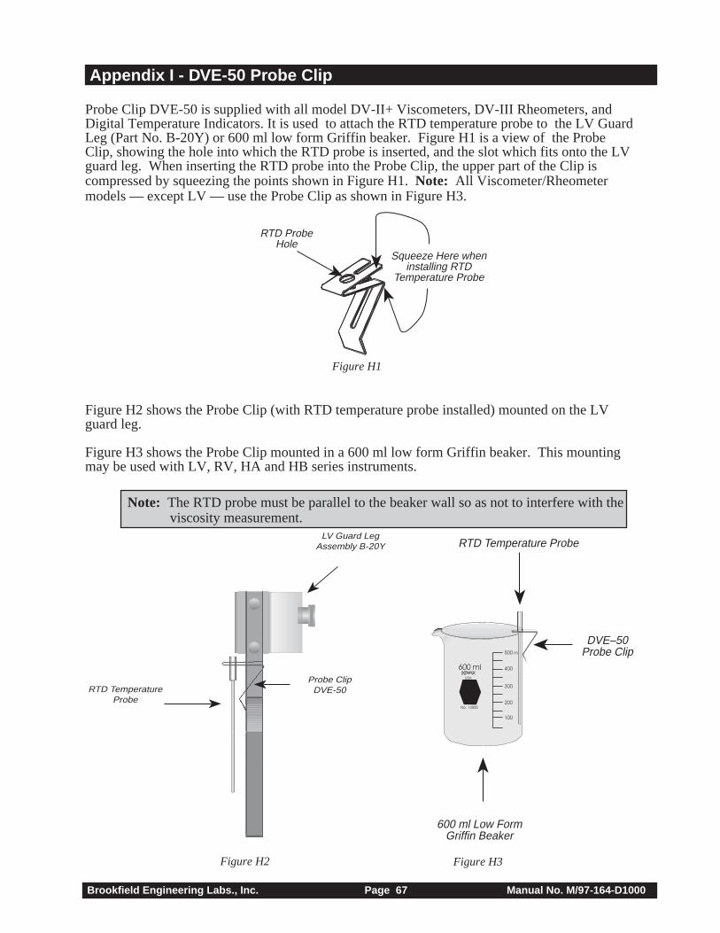
Brookfield Engineering Labs., Inc. Page 67 Manual No. M/97-164-D1000
Appendix I - DVE-50 Probe Clip
Probe Clip DVE-50 is supplied with all model DV-II+ Viscometers, DV-III Rheometers, andDigital Temperature Indicators. It is used to attach the RTD temperature probe to the LV GuardLeg (Part No. B-20Y) or 600 ml low form Griffin beaker. Figure H1 is a view of the ProbeClip, showing the hole into which the RTD probe is inserted, and the slot which fits onto the LVguard leg. When inserting the RTD probe into the Probe Clip, the upper part of the Clip iscompressed by squeezing the points shown in Figure H1. Note: All Viscometer/Rheometermodels — except LV — use the Probe Clip as shown in Figure H3.
Figure H2 shows the Probe Clip (with RTD temperature probe installed) mounted on the LVguard leg.
Figure H3 shows the Probe Clip mounted in a 600 ml low form Griffin beaker. This mountingmay be used with LV, RV, HA and HB series instruments.
Note: The RTD probe must be parallel to the beaker wall so as not to interfere with theviscosity measurement.
Figure H2 Figure H3
RTD ProbeHole
Squeeze Here wheninstalling RTD
Temperature Probe
Figure H1
LV Guard LegAssembly B-20Y
Probe ClipDVE-50RTD Temperature
Probe
600 ml
500 ml
400
300
200
100
USA
No. 14000
600 ml Low FormGriffin Beaker
DVE–50Probe Clip
RTD Temperature Probe
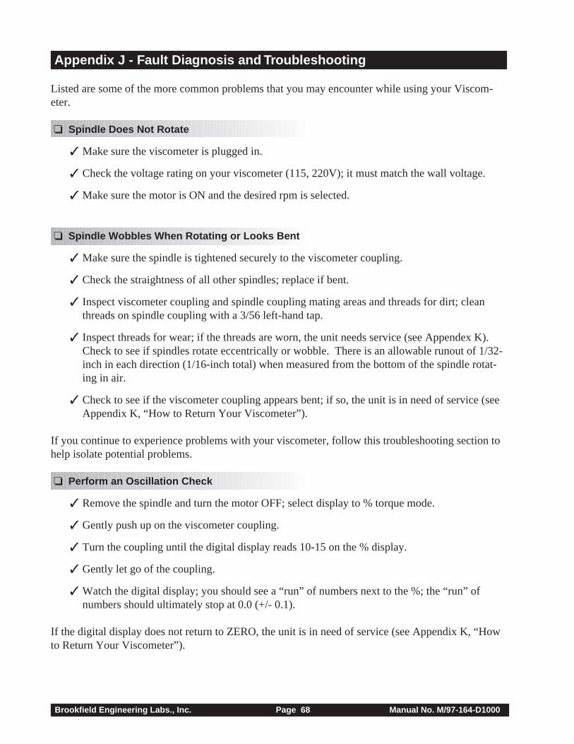
Brookfield Engineering Labs., Inc. Page 68 Manual No. M/97-164-D1000
Appendix J - Fault Diagnosis and Troubleshooting
Listed are some of the more common problems that you may encounter while using your Viscom-eter.
❏ Spindle Does Not Rotate
✓ Make sure the viscometer is plugged in.
✓ Check the voltage rating on your viscometer (115, 220V); it must match the wall voltage.
✓ Make sure the motor is ON and the desired rpm is selected.
❏ Spindle Wobbles When Rotating or Looks Bent
✓ Make sure the spindle is tightened securely to the viscometer coupling.
✓ Check the straightness of all other spindles; replace if bent.
✓ Inspect viscometer coupling and spindle coupling mating areas and threads for dirt; cleanthreads on spindle coupling with a 3/56 left-hand tap.
✓ Inspect threads for wear; if the threads are worn, the unit needs service (see Appendex K).Check to see if spindles rotate eccentrically or wobble. There is an allowable runout of 1/32-inch in each direction (1/16-inch total) when measured from the bottom of the spindle rotat-ing in air.
✓ Check to see if the viscometer coupling appears bent; if so, the unit is in need of service (seeAppendix K, “How to Return Your Viscometer”).
If you continue to experience problems with your viscometer, follow this troubleshooting section tohelp isolate potential problems.
❏ Perform an Oscillation Check
✓ Remove the spindle and turn the motor OFF; select display to % torque mode.
✓ Gently push up on the viscometer coupling.
✓ Turn the coupling until the digital display reads 10-15 on the % display.
✓ Gently let go of the coupling.
✓ Watch the digital display; you should see a “run” of numbers next to the %; the “run” ofnumbers should ultimately stop at 0.0 (+/- 0.1).
If the digital display does not return to ZERO, the unit is in need of service (see Appendix K, “Howto Return Your Viscometer”).
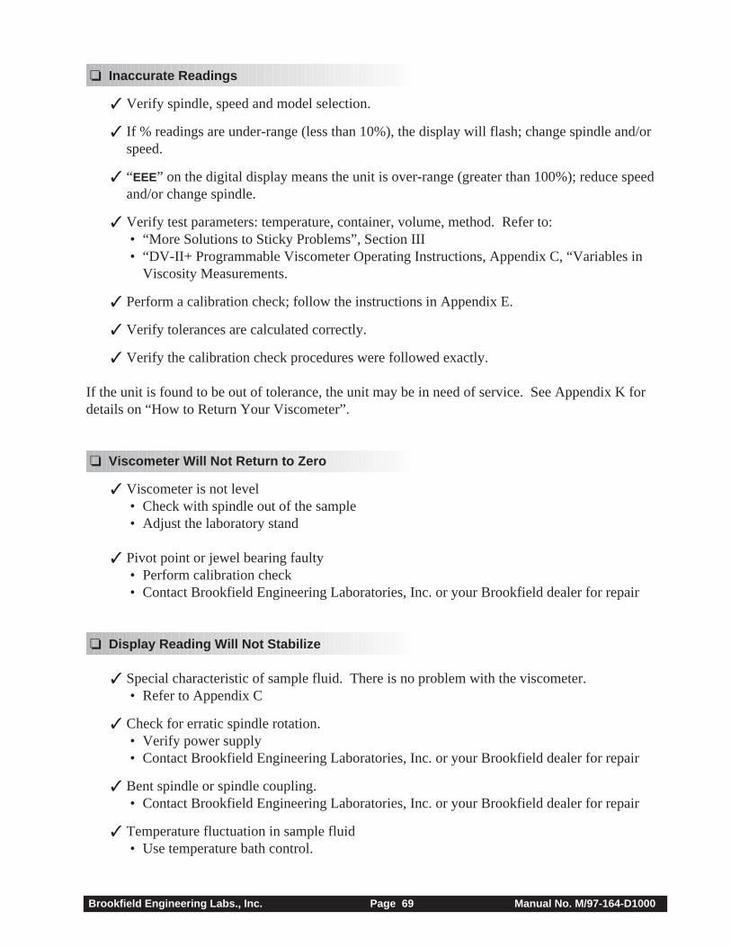
Brookfield Engineering Labs., Inc. Page 69 Manual No. M/97-164-D1000
❏ Inaccurate Readings
✓ Verify spindle, speed and model selection.
✓ If % readings are under-range (less than 10%), the display will flash; change spindle and/orspeed.
✓ “EEE” on the digital display means the unit is over-range (greater than 100%); reduce speedand/or change spindle.
✓ Verify test parameters: temperature, container, volume, method. Refer to: • “More Solutions to Sticky Problems”, Section III • “DV-II+ Programmable Viscometer Operating Instructions, Appendix C, “Variables in
Viscosity Measurements.
✓ Perform a calibration check; follow the instructions in Appendix E.
✓ Verify tolerances are calculated correctly.
✓ Verify the calibration check procedures were followed exactly.
If the unit is found to be out of tolerance, the unit may be in need of service. See Appendix K fordetails on “How to Return Your Viscometer”.
❏ Viscometer Will Not Return to Zero
✓ Viscometer is not level • Check with spindle out of the sample • Adjust the laboratory stand
✓ Pivot point or jewel bearing faulty • Perform calibration check • Contact Brookfield Engineering Laboratories, Inc. or your Brookfield dealer for repair
❏ Display Reading Will Not Stabilize
✓ Special characteristic of sample fluid. There is no problem with the viscometer. • Refer to Appendix C
✓ Check for erratic spindle rotation. • Verify power supply • Contact Brookfield Engineering Laboratories, Inc. or your Brookfield dealer for repair
✓ Bent spindle or spindle coupling. • Contact Brookfield Engineering Laboratories, Inc. or your Brookfield dealer for repair
✓ Temperature fluctuation in sample fluid • Use temperature bath control.
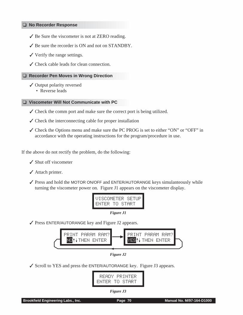
Brookfield Engineering Labs., Inc. Page 70 Manual No. M/97-164-D1000
If the above do not rectify the problem, do the following:
✓ Shut off viscometer
✓ Attach printer.
✓ Press and hold the MOTOR ON/OFF and ENTER/AUTORANGE keys simulanteously whileturning the viscometer power on. Figure J1 appears on the viscometer display.
VISCOMETER SETUPENTER TO START
Figure J1
✓ Press ENTER/AUTORANGE key and Figure J2 appears.
PRINT PARAM RAM? NO THEN ENTER
PRINT PARAM RAM?YES THEN ENTER
Figure J2
✓ Scroll to YES and press the ENTER/AUTORANGE key. Figure J3 appears.
READY PRINTERENTER TO START
Figure J3
❏ No Recorder Response
✓ Be Sure the viscometer is not at ZERO reading.
✓ Be sure the recorder is ON and not on STANDBY.
✓ Verify the range settings.
✓ Check cable leads for clean connection.
❏ Recorder Pen Moves in Wrong Direction
✓ Output polarity reversed • Reverse leads
❏ Viscometer Will Not Communicate with PC
✓ Check the comm port and make sure the correct port is being utilized.
✓ Check the interconnecting cable for proper installation
✓ Check the Options menu and make sure the PC PROG is set to either “ON” or “OFF” inaccordance with the operating instructions for the program/procedure in use.
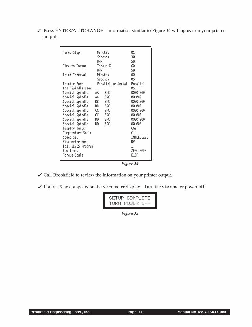
Brookfield Engineering Labs., Inc. Page 71 Manual No. M/97-164-D1000
✓ Press ENTER/AUTORANGE. Information similar to Figure J4 will appear on your printeroutput.
Timed Stop Minutes 01Seconds 30RPM 50
Time to Torque Torque % 60RPM 50
Print Interval Minutes 00Seconds 05
Printer Port Parallel or Serial ParallelLast Spindle Used 05Special Spindle AA SMC 0000.000Special Spindle AA SRC 00.000Special Spindle BB SMC 0000.000Special Spindle BB SRC 00.000Special Spindle CC SMC 0000.000Special Spindle CC SRC 00.000Special Spindle DD SMC 0000.000Special Spindle DD SRC 00.000Display Units CGSTemperature Scale CSpeed Set INTERLEAVEViscometer Model RVLast BEVIS Program 1Raw Temps 2E0C 00FETorque Scale E19F
Figure J4
✓ Call Brookfield to review the information on your printer output.
✓ Figure J5 next appears on the viscometer display. Turn the viscometer power off.
SETUP COMPLETE TURN POWER OFF
Figure J5
Brookfield Engineering Labs., Inc. Page 72 Manual No. M/97-164-D1000
Appendix K - Warranty Repair and Service
Warranty
Brookfield Viscometers are guaranteed for one year from date of purchase against defects in materialsand workmanship. They are certified against primary viscosity standards traceable to the NationalInstitute of Standards and Technology (NIST). The Viscometer must be returned to BrookfieldEngineering Laboratories, Inc. or the Brookfield dealer from whom it was purchased for no chargewarranty service. Transportation is at the purchaser’s expense. The Viscometer should be shipped inits carrying case together with all spindles originally provided with the instrument.
For repair or service in the United States, return to:
Brookfield Engineering Laboratories, Inc.11 Commerce Boulevard
Middleboro, MA 02346 U.S.A.
Telephone: (508) 946-6200 FAX: (508) 946-6262http://www.brookfieldengineering.com
For repair or service outside the United States consult Brookfield Engineering Laboratories, Inc.or the dealer from whom you purchased the instrument.
For repair or service in the United Kingdom return to:
Brookfield Viscometers Limited1 Whitehall Estate
Flex MeadowPinnacles West
Harlow, Essex CM19 5TJ, United Kingdom
Telephone: (44) 27/945 1774 FAX: (44) 27/945 1775
For repair or service in Germany return to:
Brookfield Engineering Laboratories Vertriebs GmbHBarbarossastrasse 3
D-73547 Lorch, Germany
Telephone: (49) 7172/927100 FAX: (49) 7172/927105
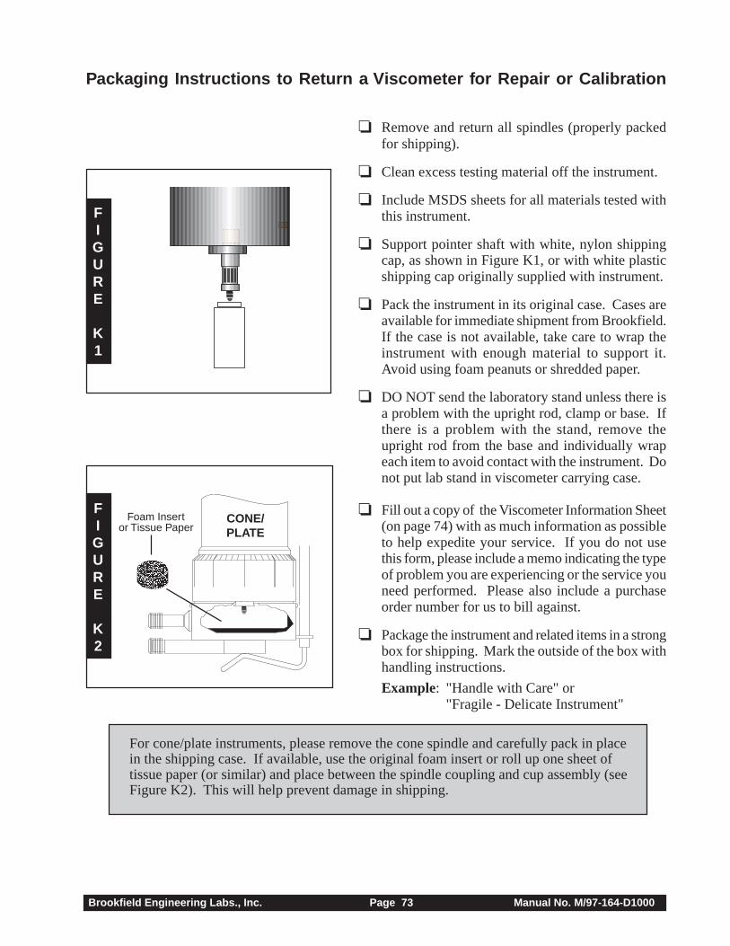
Brookfield Engineering Labs., Inc. Page 73 Manual No. M/97-164-D1000
❏ Remove and return all spindles (properly packedfor shipping).
❏ Clean excess testing material off the instrument.
❏ Include MSDS sheets for all materials tested withthis instrument.
❏ Support pointer shaft with white, nylon shippingcap, as shown in Figure K1, or with white plasticshipping cap originally supplied with instrument.
❏ Pack the instrument in its original case. Cases areavailable for immediate shipment from Brookfield.If the case is not available, take care to wrap theinstrument with enough material to support it.Avoid using foam peanuts or shredded paper.
❏ DO NOT send the laboratory stand unless there isa problem with the upright rod, clamp or base. Ifthere is a problem with the stand, remove theupright rod from the base and individually wrapeach item to avoid contact with the instrument. Donot put lab stand in viscometer carrying case.
❏ Fill out a copy of the Viscometer Information Sheet(on page 74) with as much information as possibleto help expedite your service. If you do not usethis form, please include a memo indicating the typeof problem you are experiencing or the service youneed performed. Please also include a purchaseorder number for us to bill against.
❏ Package the instrument and related items in a strongbox for shipping. Mark the outside of the box withhandling instructions.
Example: "Handle with Care" or"Fragile - Delicate Instrument"
For cone/plate instruments, please remove the cone spindle and carefully pack in placein the shipping case. If available, use the original foam insert or roll up one sheet oftissue paper (or similar) and place between the spindle coupling and cup assembly (seeFigure K2). This will help prevent damage in shipping.
CONE/PLATE
Packaging Instructions to Return a Viscometer for Repair or Calibration
FIGURE
K1
FIGURE
K2
aaaaaaaaaaaaaaaaaaaaFoam Insertor Tissue Paper
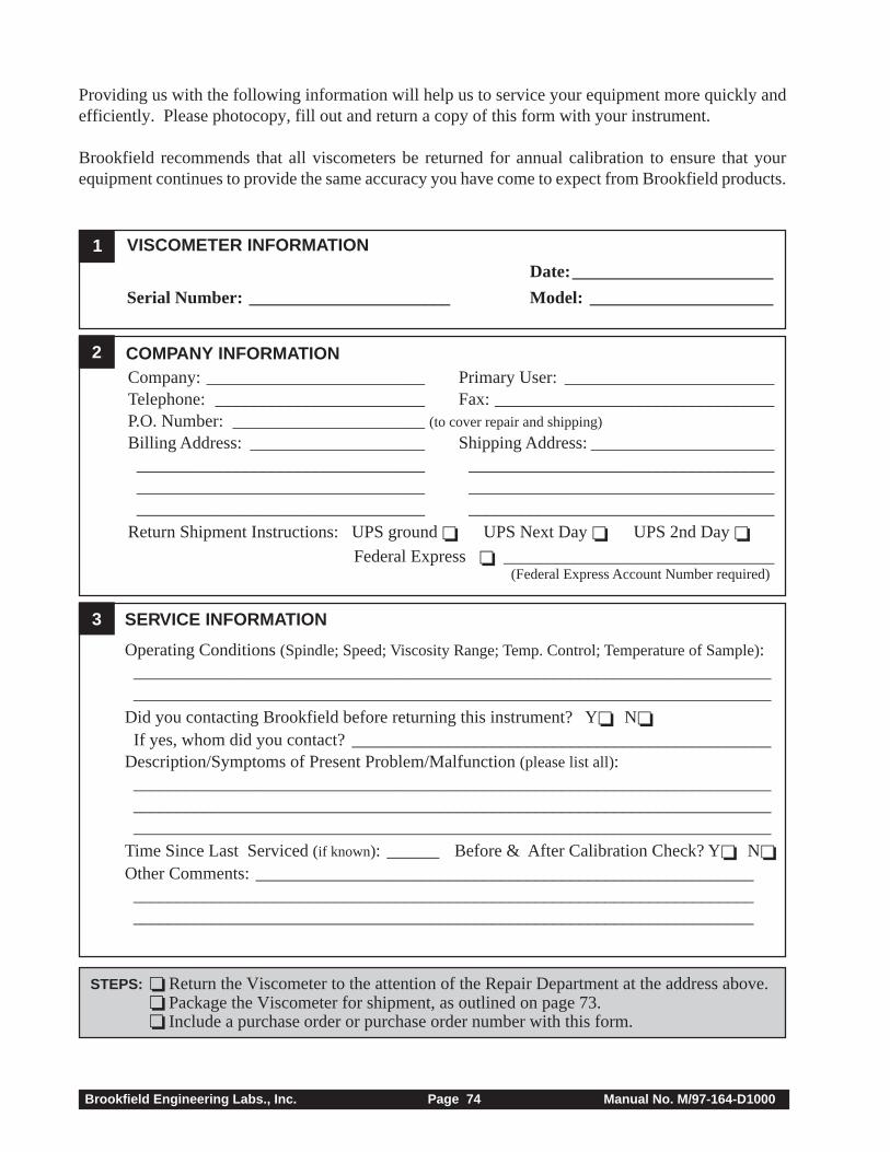
Brookfield Engineering Labs., Inc. Page 74 Manual No. M/97-164-D1000
Providing us with the following information will help us to service your equipment more quickly andefficiently. Please photocopy, fill out and return a copy of this form with your instrument.
Brookfield recommends that all viscometers be returned for annual calibration to ensure that yourequipment continues to provide the same accuracy you have come to expect from Brookfield products.
COMPANY INFORMATION
3 SERVICE INFORMATION
Operating Conditions (Spindle; Speed; Viscosity Range; Temp. Control; Temperature of Sample):__________________________________________________________________________________________________________________________________________________
Did you contacting Brookfield before returning this instrument? Y❏ N❏ If yes, whom did you contact? ________________________________________________Description/Symptoms of Present Problem/Malfunction (please list all):___________________________________________________________________________________________________________________________________________________________________________________________________________________________
Time Since Last Serviced (if known): ______ Before & After Calibration Check? Y❏ N❏Other Comments: _______________________________________________________________________________________________________________________________________________________________________________________________________
1
2
VISCOMETER INFORMATION
Date:_______________________
Serial Number: _______________________ Model: _____________________
Company: _________________________ Primary User: ________________________Telephone: ________________________ Fax: ________________________________P.O. Number: ______________________(to cover repair and shipping)
Billing Address: ____________________ Shipping Address: ______________________________________________________ ____________________________________________________________________ ____________________________________________________________________ ___________________________________
Return Shipment Instructions: UPS ground ❏ UPS Next Day ❏ UPS 2nd Day ❏Federal Express ❏ _______________________________
(Federal Express Account Number required)
STEPS: ❏ Return the Viscometer to the attention of the Repair Department at the address above.❏ Package the Viscometer for shipment, as outlined on page 73.❏ Include a purchase order or purchase order number with this form.
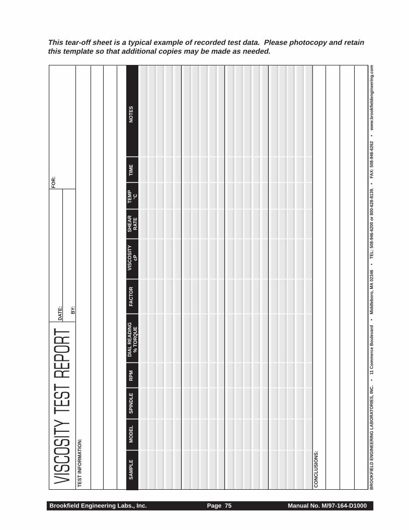
Brookfield Engineering Labs., Inc. Page 75 Manual No. M/97-164-D1000
VISCO
SITY
TEST
REP
ORT
SA
MP
LEM
OD
EL
SP
IND
LER
PM
DIA
L R
EA
DIN
GFA
CTO
RV
ISC
OS
ITY
SH
EA
RTE
MP
TIM
EN
OTE
S%
TO
RQ
UE
cPR
ATE
°C
TES
T IN
FOR
MAT
ION
:
CO
NC
LUS
ION
S:
FOR
:D
ATE
:
BY:
BR
OO
KFI
ELD
EN
GIN
EE
RIN
G L
AB
OR
ATO
RIE
S, I
NC
. •
1
1 C
omm
erce
Bou
leva
rd
•
Mid
dleb
oro,
MA
023
46
•
TEL:
508
-946
-620
0 or
800
-628
-813
9.
• F
AX
: 508
-946
-626
2
• w
ww
.bro
okfie
lden
gine
erin
g.co
m
This tear-off sheet is a typical example of recorded test data. Please photocopy and retainthis template so that additional copies may be made as needed.