Embed Size (px)
Citation preview
Brookfield Engineering Laboratories, Inc. Page � Manual No. M/07-022
BROOKFIELD DIGITAL VISCOMETER
MODEL DV-I PRIME
Operating Instructions
Manual No. M/07-022
Please record the Model and Serial Number of your viscometer. Hav-ing this information readily available will help us to assist you should there be any questions regarding your instrument.
Model No.
Serial No.
Date Purchased
SPECIALISTS IN THE
MEASUREMENT AND
CONTROL OF VISCOSITY
TEL 508-946-6200FAX 508-946-6262
or 800-628-8139 (USA excluding MA)INTERNET http://www.brookfieldengineering.com
BROOKFIELD ENGINEERING LABORATORIES, INC.11 Commerce Boulevard, Middleboro, MA 02346 USA
with offices in: Boston • Chicago • London • Stuttgart • Guangzhou
Brookfield Engineering Laboratories, Inc. Page 2 Manual No. M/07-022
TABLE OF CONTENTS
I. INTRODUCTION ....................................................................................... 3 I.1 Components ...................................................................................................................... 4 I.2 Utilities .............................................................................................................................. 4 I.3 Specifications .................................................................................................................... 6 I.4 Set-Up ............................................................................................................................... 6 I.5 Safety Symbols and Precautions ....................................................................................... 7 I.6 Key Functions ................................................................................................................... 8 I.7 Cleaning ............................................................................................................................ 9
II. GETTING STARTED ................................................................................10 II.1 Auto Zero ........................................................................................................................ 10 II.2 Spindle Selection ............................................................................................................ 11 II.3 Speed Selection ............................................................................................................... 13 II.4 Autorange ........................................................................................................................ 14 II.5 CGS or SI Units Selection ............................................................................................. 15 II.6 Temperature Display in °F or °C Selection..................................................................... 15 II.7 Out of Range .................................................................................................................. 15 II.8 Operation ......................................................................................................................... 16 II.9 Timed Modes / Temperature Offset ................................................................................ 16 II.10 Print Modes ..................................................................................................................... 21 II.11 Communicating with Wingather Software ...................................................................... 23
III. MAKING VISCOSITY MEASUREMENTS ..............................................24III.1 Quick Start .................................................................................................................... 24III.2 Preparations for Making Measurements ......................................................................... 24III.3 Selecting a Spindle/Speed ............................................................................................... 25III.4 Multiple Data Points ....................................................................................................... 25
Appendix A - Cone/Plate Viscometer Set-Up .............................................................................. 27 Appendix B - Viscosity Ranges .................................................................................................... 32 Appendix C - Variables in Viscosity Measurement ...................................................................... 36 Appendix D - Spindle and Model Codes ...................................................................................... 38 Appendix E - Calibration Procedures........................................................................................... 40 Appendix F - Communications .................................................................................................... 48 Appendix G - Laboratory Stand with Parts Identification ............................................................ 49 Appendix H - DVE-50A Temperature Probe Clip ........................................................................ 51 Appendix I - Fault Diagnosis and Troubleshooting .................................................................... 52 Appendix J - Warranty Repair and Service ................................................................................. 54 Appendix K - Viscosity Test Report ............................................................................................. 57
Brookfield Engineering Laboratories, Inc. Page � Manual No. M/07-022
I. INTRODUCTION
The Brookfield DV-I PRIME Viscometer measures fluid viscosity at given shear rate. Viscosity is a measure of a fluid’s resistance to flow. You will find a detailed description of the science of viscosity in the Brookfield publication “More Solutions to Sticky Problems” a copy of which was included with your DV-I PRIME.
The principle of operation of the DV-I PRIME is to drive a spindle (which is immersed in the test fluid) through a calibrated spring. The viscous drag of the fluid against the spindle is measured by the spring deflection. Spring deflection is measured with a rotary transducer. This system provides continuous sensing and display of the measurement during the entire test. The measurement range of a DV-I PRIME (in centipoise or milliPascal-seconds) is determined by the rotational speed of the spindle, the size and shape of the spindle, the container the spindle is rotating in, and the full scale torque of the calibrated spring.
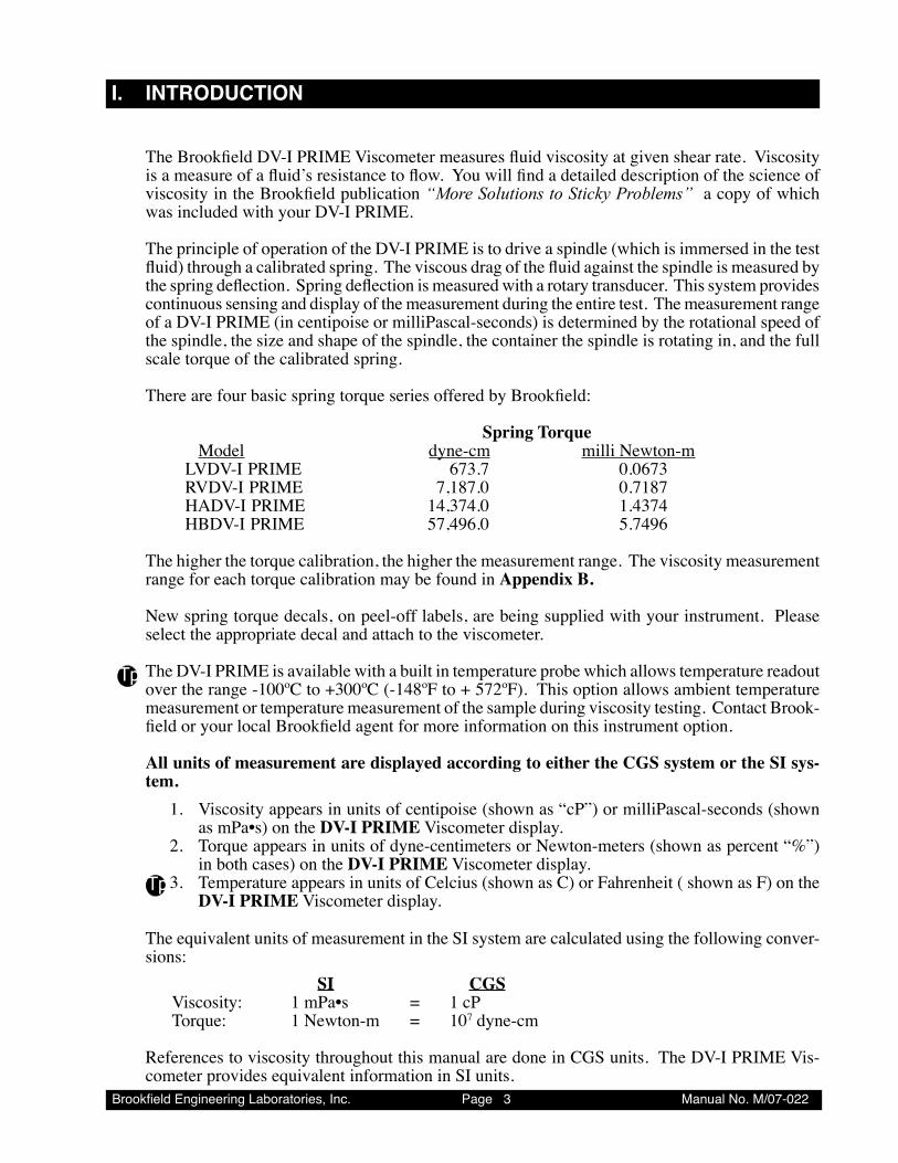
There are four basic spring torque series offered by Brookfield:
Spring TorqueModel dyne-cm milli Newton-m
LVDV-I PRIME 673.7 0.0673RVDV-I PRIME 7,187.0 0.7187HADV-I PRIME 14,374.0 1.4374HBDV-I PRIME 57,496.0 5.7496
The higher the torque calibration, the higher the measurement range. The viscosity measurement range for each torque calibration may be found in Appendix B.
New spring torque decals, on peel-off labels, are being supplied with your instrument. Please select the appropriate decal and attach to the viscometer. The DV-I PRIME is available with a built in temperature probe which allows temperature readout over the range -100ºC to +300ºC (-148ºF to + 572ºF). This option allows ambient temperature measurement or temperature measurement of the sample during viscosity testing. Contact Brook-field or your local Brookfield agent for more information on this instrument option.
All units of measurement are displayed according to either the CGS system or the SI sys-tem.
1. Viscosity appears in units of centipoise (shown as “cP”) or milliPascal-seconds (shown as mPa•s) on the DV-I PRIME Viscometer display.
2. Torque appears in units of dyne-centimeters or Newton-meters (shown as percent “%”) in both cases) on the DV-I PRIME Viscometer display.
Tp3. Temperature appears in units of Celcius (shown as C) or Fahrenheit ( shown as F) on the DV-I PRIME Viscometer display.
The equivalent units of measurement in the SI system are calculated using the following conver-sions:
SI CGSViscosity: 1 mPa•s = 1 cPTorque: 1 Newton-m = 107 dyne-cm
References to viscosity throughout this manual are done in CGS units. The DV-I PRIME Vis-cometer provides equivalent information in SI units.
Tp
Brookfield Engineering Laboratories, Inc. Page � Manual No. M/07-022
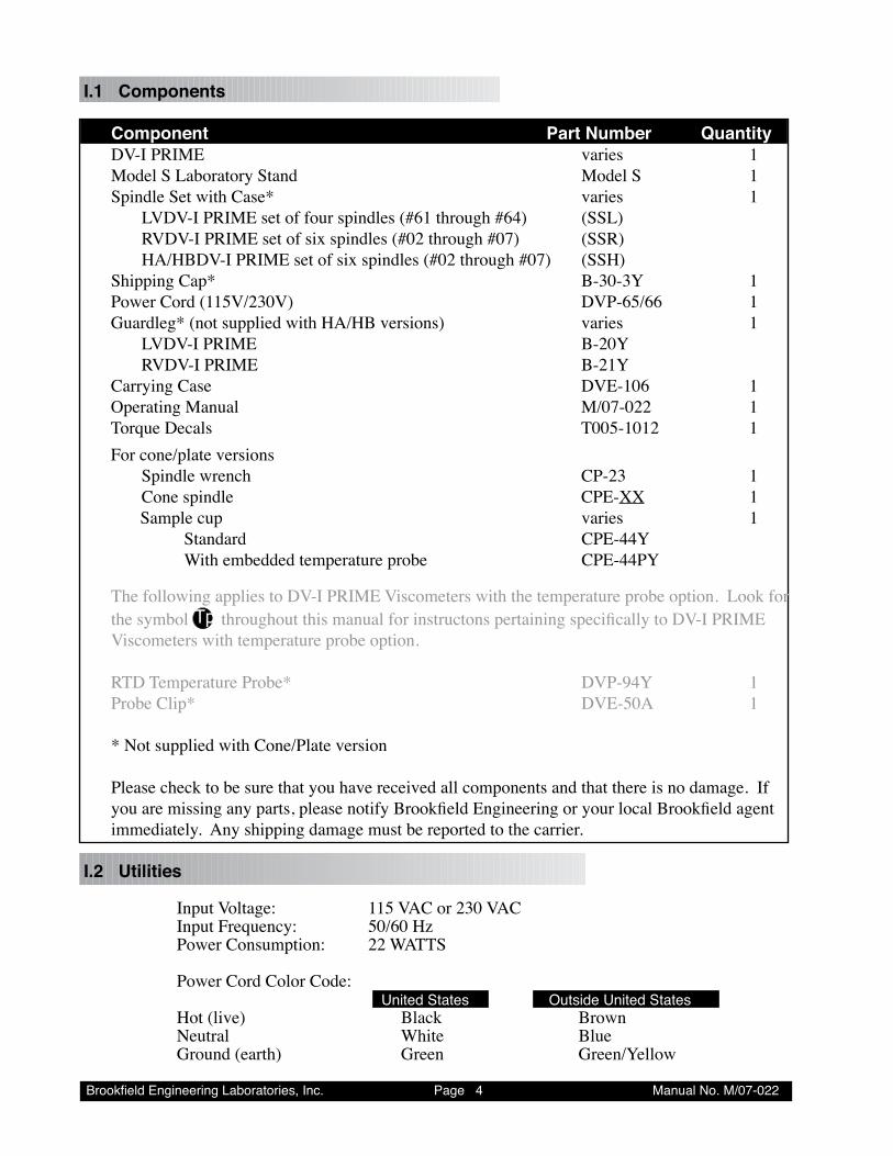
I.1 Components
Component Part Number Quantity DV-I PRIME varies 1 Model S Laboratory Stand Model S 1 Spindle Set with Case* varies 1 LVDV-I PRIME set of four spindles (#61 through #64) (SSL) RVDV-I PRIME set of six spindles (#02 through #07) (SSR) HA/HBDV-I PRIME set of six spindles (#02 through #07) (SSH) Shipping Cap* B-30-3Y 1 Power Cord (115V/230V) DVP-65/66 1 Guardleg* (not supplied with HA/HB versions) varies 1 LVDV-I PRIME B-20Y RVDV-I PRIME B-21Y Carrying Case DVE-106 1 Operating Manual M/07-022 1 Torque Decals T005-1012 1 For cone/plate versions Spindle wrench CP-23 1 Cone spindle CPE-XX 1
Sample cup varies 1 Standard CPE-44Y With embedded temperature probe CPE-44PY
The following applies to DV-I PRIME Viscometers with the temperature probe option. Look for
the symbol Tp throughout this manual for instructons pertaining specifically to DV-I PRIME Viscometers with temperature probe option.
RTD Temperature Probe* DVP-94Y 1 Probe Clip* DVE-50A 1 * Not supplied with Cone/Plate version Please check to be sure that you have received all components and that there is no damage. If
you are missing any parts, please notify Brookfield Engineering or your local Brookfield agent immediately. Any shipping damage must be reported to the carrier.
I.2 Utilities
Input Voltage: 115 VAC or 230 VACInput Frequency: 50/60 HzPower Consumption: 22 WATTS
Power Cord Color Code: United States Outside United StatesHot (live) Black BrownNeutral White BlueGround (earth) Green Green/Yellow
Brookfield Engineering Laboratories, Inc. Page � Manual No. M/07-022
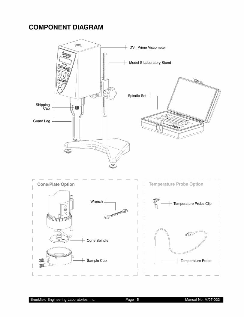
COMPONENT DIAGRAM
Cone/Plate Option Temperature Probe Option
Model S Laboratory Stand
Spindle Set
DV-I Prime Viscometer
Cone Spindle
Wrench
Sample Cup
Temperature Probe Clip
Temperature Probe
Guard Leg
ShippingCap
Brookfield Engineering Laboratories, Inc. Page � Manual No. M/07-022
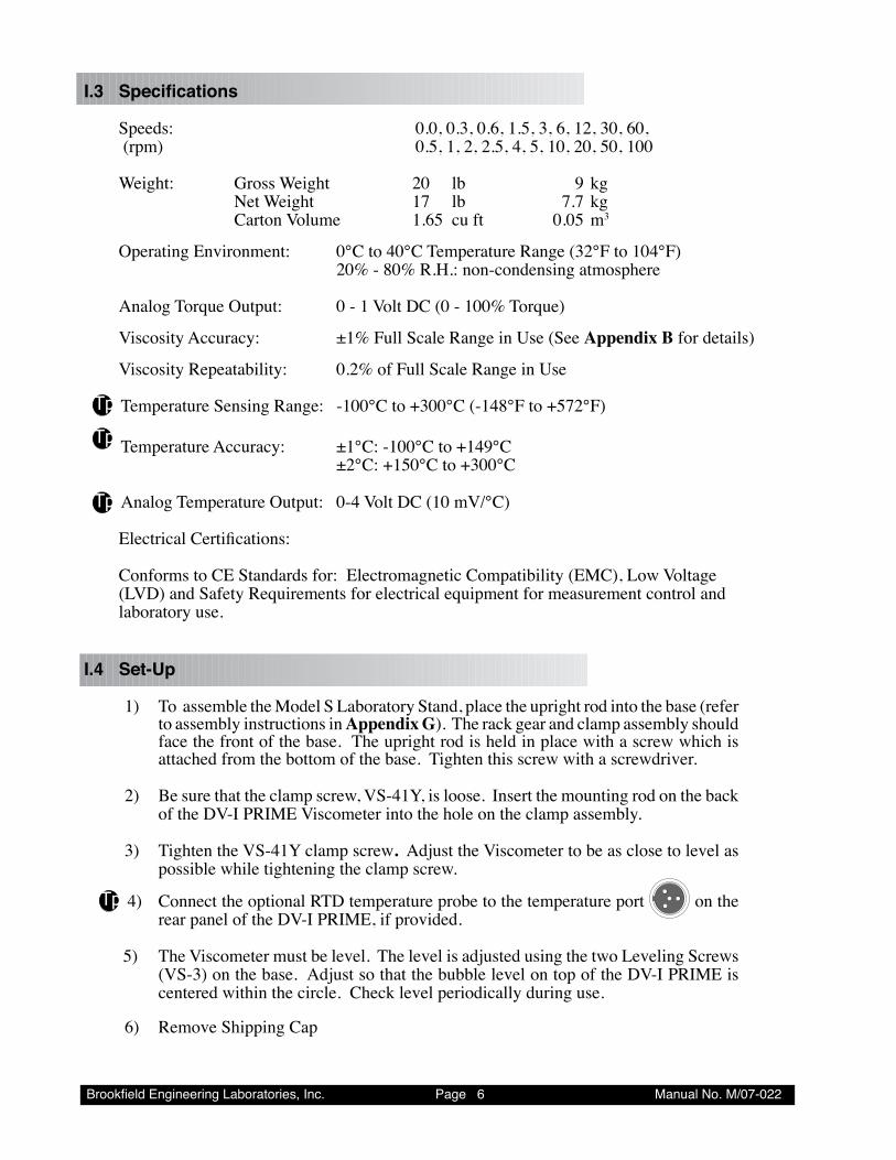
I.3 Specifications
Speeds: 0.0, 0.3, 0.6, 1.5, 3, 6, 12, 30, 60, (rpm) 0.5, 1, 2, 2.5, 4, 5, 10, 20, 50, 100
Weight: Gross Weight 20 lb 9 kg Net Weight 17 lb 7.7 kg Carton Volume 1.65 cu ft 0.05 m3
Operating Environment: 0°C to 40°C Temperature Range (32°F to 104°F) 20% - 80% R.H.: non-condensing atmosphere
Analog Torque Output: 0 - 1 Volt DC (0 - 100% Torque)
Viscosity Accuracy: ±1% Full Scale Range in Use (See Appendix B for details)
Viscosity Repeatability: 0.2% of Full Scale Range in Use
Tp Temperature Sensing Range: -100°C to +300°C (-148°F to +572°F)
Tp Temperature Accuracy: ±1°C: -100°C to +149°C ±2°C: +150°C to +300°C
Tp Analog Temperature Output: 0-4 Volt DC (10 mV/°C)
Electrical Certifications:
Conforms to CE Standards for: Electromagnetic Compatibility (EMC), Low Voltage (LVD) and Safety Requirements for electrical equipment for measurement control and laboratory use.
I.4 Set-Up
1) To assemble the Model S Laboratory Stand, place the upright rod into the base (refer to assembly instructions in Appendix G). The rack gear and clamp assembly should face the front of the base. The upright rod is held in place with a screw which is attached from the bottom of the base. Tighten this screw with a screwdriver.
2) Be sure that the clamp screw, VS-41Y, is loose. Insert the mounting rod on the back of the DV-I PRIME Viscometer into the hole on the clamp assembly.
3) Tighten the VS-41Y clamp screw. Adjust the Viscometer to be as close to level as possible while tightening the clamp screw.
Tp 4) Connect the optional RTD temperature probe to the temperature port on the rear panel of the DV-I PRIME, if provided.
5) The Viscometer must be level. The level is adjusted using the two Leveling Screws (VS-3) on the base. Adjust so that the bubble level on top of the DV-I PRIME is centered within the circle. Check level periodically during use.
6) Remove Shipping Cap
Brookfield Engineering Laboratories, Inc. Page 7 Manual No. M/07-022
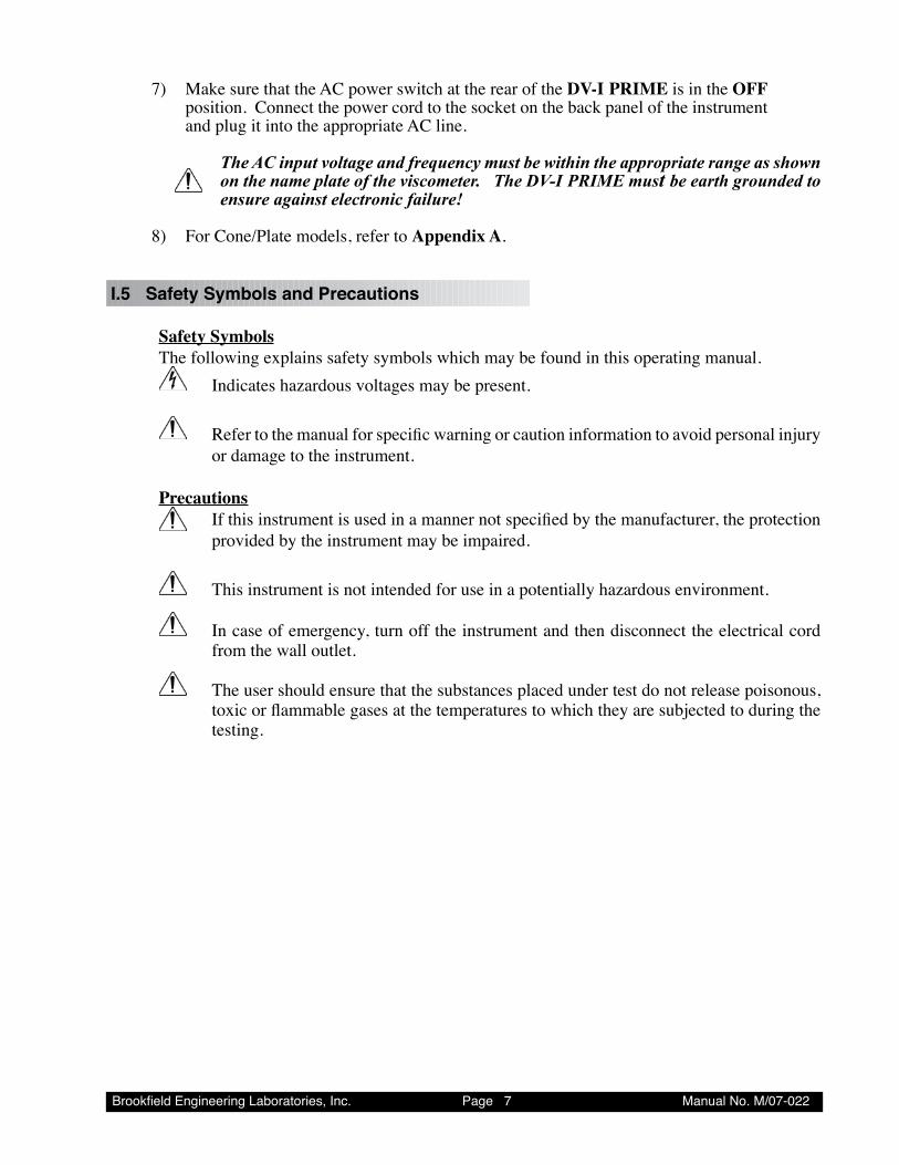
7) Make sure that the AC power switch at the rear of the DV-I PRIME is in the OFF position. Connect the power cord to the socket on the back panel of the instrument and plug it into the appropriate AC line.
The AC input voltage and frequency must be within the appropriate range as shown on the name plate of the viscometer. The DV-I PRIME must be earth grounded to ensure against electronic failure!
8) For Cone/Plate models, refer to Appendix A.
I.5 Safety Symbols and Precautions
Safety Symbols The following explains safety symbols which may be found in this operating manual. Indicates hazardous voltages may be present. Refer to the manual for specific warning or caution information to avoid personal injury
or damage to the instrument.
Precautions If this instrument is used in a manner not specified by the manufacturer, the protection
provided by the instrument may be impaired.
This instrument is not intended for use in a potentially hazardous environment.
In case of emergency, turn off the instrument and then disconnect the electrical cord from the wall outlet.
The user should ensure that the substances placed under test do not release poisonous, toxic or flammable gases at the temperatures to which they are subjected to during the testing.
Brookfield Engineering Laboratories, Inc. Page � Manual No. M/07-022
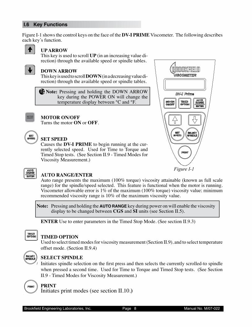
I.6 Key Functions
Figure I-1 shows the control keys on the face of the DV-I PRIME Viscometer. The following describes each key’s function.
UP ARROW This key is used to scroll UP (in an increasing value di-
rection) through the available speed or spindle tables.
DOWN ARROW This key is used to scroll DOWN (in a decreasing value di-
rection) through the available speed or spindle tables.
TpNote: Pressing and holding the DOWN ARROW key during the POWER ON will change the temperature display between °C and °F.
MOTOR
ON/OFF MOTOR ON/OFF Turns the motor ON or OFF.
SET SPEED Causes the DV-I PRIME to begin running at the cur-
rently selected speed. Used for Time to Torque and Timed Stop tests. (See Section II.9 - Timed Modes for Viscosity Measurement.)
AUTO RANGE/ENTER Auto range presents the maximum (100% torque) viscosity attainable (known as full scale
range) for the spindle/speed selected. This feature is functional when the motor is running. Viscometer allowable error is 1% of the maximum (100% torque) viscosity value; minimum recommended viscosity range is 10% of the maximum viscosity value.
Note: Pressing and holding the AUTO RANGE key during power on will enable the viscosity
display to be changed between CGS and SI units (see Section II.5).
ENTER Use to enter parameters in the Timed Stop Mode. (See section II.9.3)
TIMED OPTION Used to select timed modes for viscosity measurement (Section II.9), and to select temperature
offset mode. (Section II.9.4)
SELECT SPINDLE Initiates spindle selection on the first press and then selects the currently scrolled-to spindle
when pressed a second time. Used for Time to Torque and Timed Stop tests. (See Section II.9 - Timed Modes for Viscosity Measurement.)
PRINT Initiates print modes (see section II.10.)
Figure I-1
Brookfield Engineering Laboratories, Inc. Page � Manual No. M/07-022
I.7 Cleaning
Be sure to remove spindle from instrument prior to cleaning. Note left-hand thread. Severe instrument damage may result if cleaned in place.
Instrument and Keypad: Clean with dry, non-abrasive cloth. Do not use solvents or cleaners.
Immersed Components: Spindles and guard leg are made of stainless steel. Clean with non-abrasive cloth and solvent appropriate for sample material that is not aggressive to immersed components.
When cleaning, do not apply excessive force which may result in bending spin-dles.
II. GETTING STARTED
Brookfield Engineering Laboratories, Inc. Page �0 Manual No. M/07-022
II. GETTING STARTED
II.1 Auto Zero
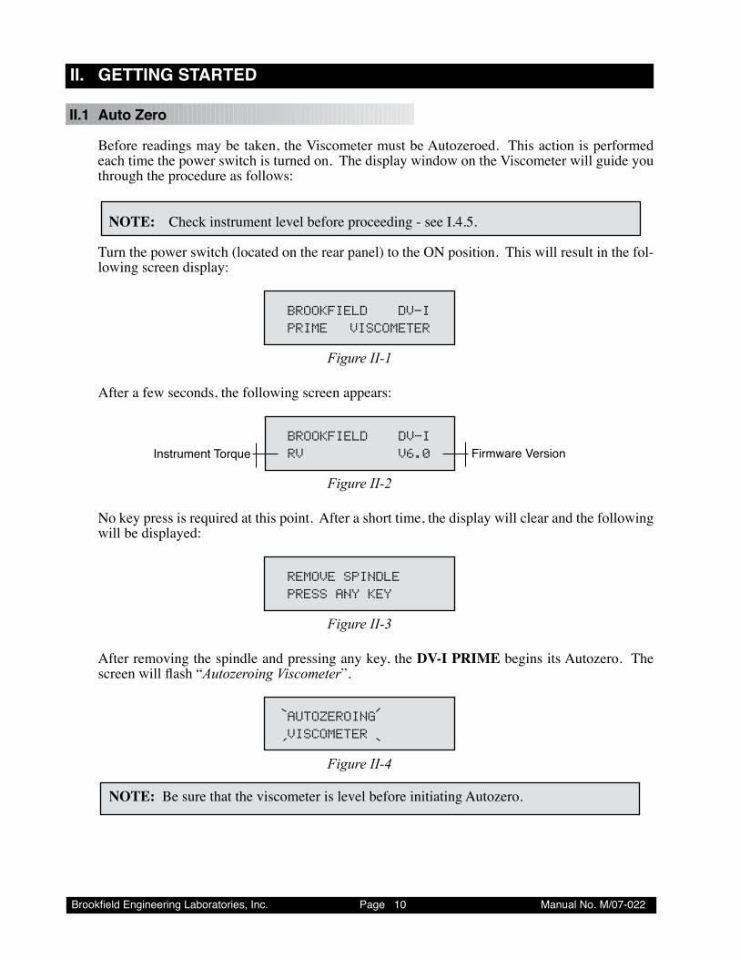
Before readings may be taken, the Viscometer must be Autozeroed. This action is performed each time the power switch is turned on. The display window on the Viscometer will guide you through the procedure as follows:
NOTE: Check instrument level before proceeding - see I.4.5.
Turn the power switch (located on the rear panel) to the ON position. This will result in the fol-lowing screen display:
BROOKFIELD DV-IPRIME VISCOMETER
Figure II-1
After a few seconds, the following screen appears:
BROOKFIELD DV-IRV V6.0 Firmware VersionInstrument Torque
Figure II-2
No key press is required at this point. After a short time, the display will clear and the following will be displayed:
REMOVESPINDLEPRESSANYKEY
Figure II-3
After removing the spindle and pressing any key, the DV-I PRIME begins its Autozero. The screen will flash “Autozeroing Viscometer”.
AUTOZEROINGVISCOMETER
Figure II-4
NOTE: Be sure that the viscometer is level before initiating Autozero.
Brookfield Engineering Laboratories, Inc. Page �� Manual No. M/07-022
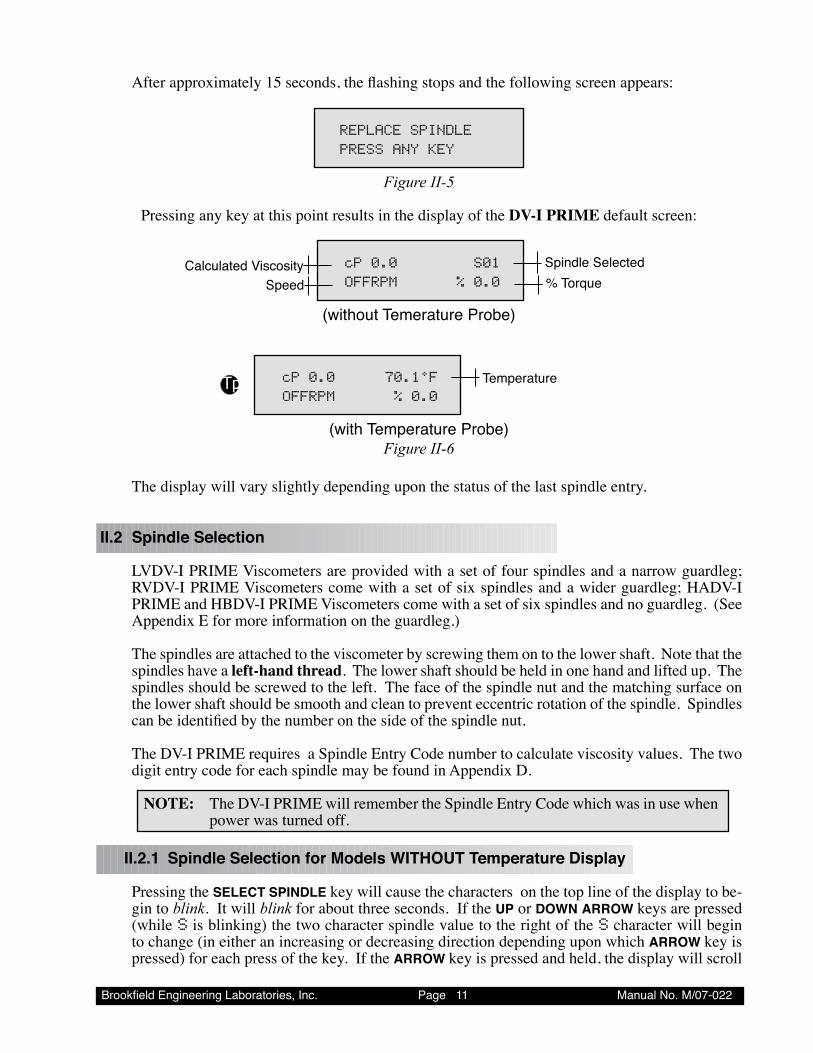
After approximately 15 seconds, the flashing stops and the following screen appears:
REPLACESPINDLEPRESSANYKEY
Figure II-5
Pressing any key at this point results in the display of the DV-I PRIME default screen:
cP0.0 S01OFFRPM %0.0
Spindle SelectedCalculated Viscosity% TorqueSpeed
(without Temerature Probe)
cP0.0 70.1°FOFFRPM %0.0
TemperatureTp
(with Temperature Probe)Figure II-6
The display will vary slightly depending upon the status of the last spindle entry.
II.2 Spindle Selection
LVDV-I PRIME Viscometers are provided with a set of four spindles and a narrow guardleg; RVDV-I PRIME Viscometers come with a set of six spindles and a wider guardleg; HADV-I PRIME and HBDV-I PRIME Viscometers come with a set of six spindles and no guardleg. (See Appendix E for more information on the guardleg.)
The spindles are attached to the viscometer by screwing them on to the lower shaft. Note that the spindles have a left-hand thread. The lower shaft should be held in one hand and lifted up. The spindles should be screwed to the left. The face of the spindle nut and the matching surface on the lower shaft should be smooth and clean to prevent eccentric rotation of the spindle. Spindles can be identified by the number on the side of the spindle nut.
The DV-I PRIME requires a Spindle Entry Code number to calculate viscosity values. The two digit entry code for each spindle may be found in Appendix D.
NOTE: The DV-I PRIME will remember the Spindle Entry Code which was in use when power was turned off.
II.2.1 Spindle Selection for Models WITHOUT Temperature Display
Pressing the SELECT SPINDLE key will cause the characters on the top line of the display to be-gin to blink. It will blink for about three seconds. If the UP or DOWN ARROW keys are pressed (while S is blinking) the two character spindle value to the right of the S character will begin to change (in either an increasing or decreasing direction depending upon which ARROW key is pressed) for each press of the key. If the ARROW key is pressed and held, the display will scroll
Brookfield Engineering Laboratories, Inc. Page �2 Manual No. M/07-022
through the spindle codes for as long as the ARROW key is depressed. When it reaches the last item in the list (either at the top or bottom of the list) the spindle code displayed will “roll-over” to either the first or last spindle code and the scroll action will continue.
When the desired spindle code is displayed, release the ARROW key to halt further scrolling. Press the SELECT SPINDLE key once again. This will cause the S character to cease blinking and the new spindle code will be accepted for use in viscometer calculations.
NOTE: You have approximately three seconds in which to press the SELECT SPINDLE key before the blinking stops. If you fail to press the SELECT SPINDLE key before the blinking stops you will have to repeat the above steps and re-select the desired spindle.
The DV-I PRIME will begin to calculate using the new spindle parameters as soon as the SELECT SPINDLE key is pressed the second time.
NOTE: The number 99 spindle is for use with special spindles when using Brookfield’s WINGATHER32 computer program. Refer to WINGATHER32 operator manual for further information on using “99” spindles.
DV-I PRIME remembers last spindle selected when power is shut down.
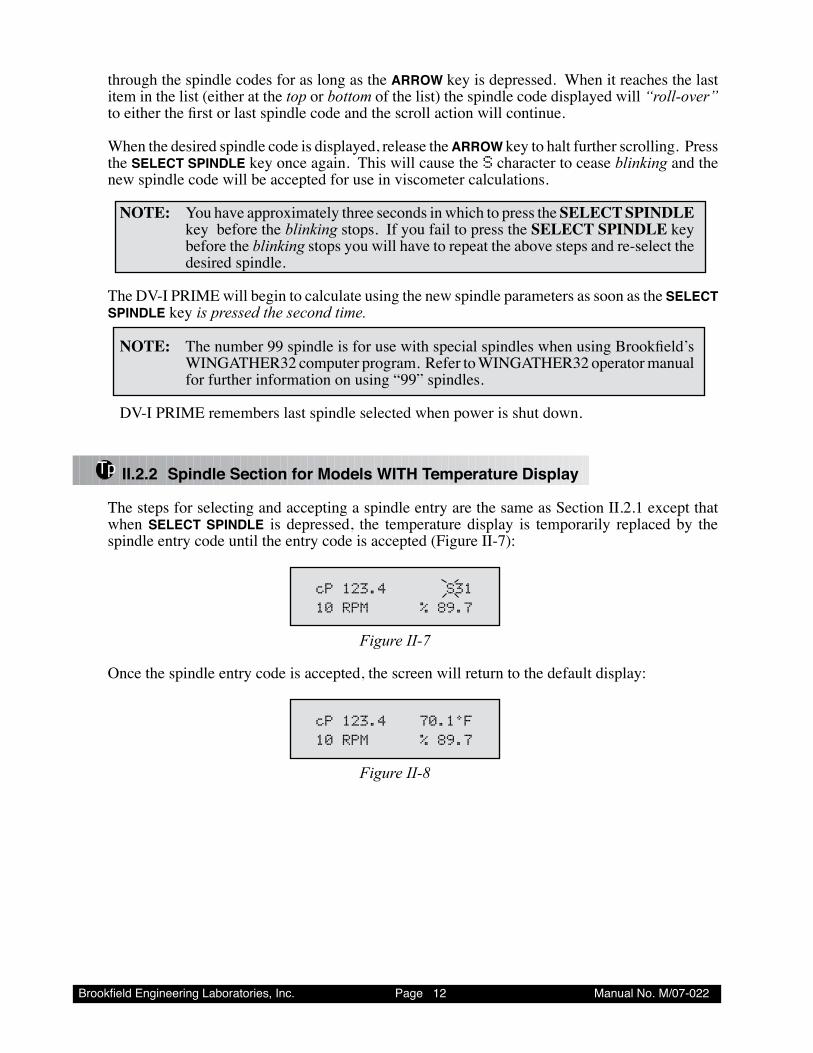
Tp II.2.2 Spindle Section for Models WITH Temperature Display
The steps for selecting and accepting a spindle entry are the same as Section II.2.1 except that when SELECT SPINDLE is depressed, the temperature display is temporarily replaced by the spindle entry code until the entry code is accepted (Figure II-7):
cP123.4 S3110RPM %89.7
Figure II-7
Once the spindle entry code is accepted, the screen will return to the default display:
cP123.4 70.1°F10RPM %89.7
Figure II-8
Brookfield Engineering Laboratories, Inc. Page �� Manual No. M/07-022
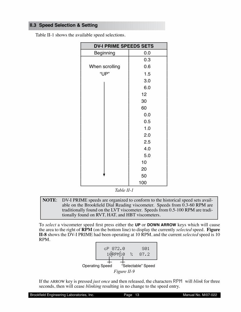
II.3 Speed Selection & Setting
Table II-1 shows the available speed selections.
DV-I PRIME SPEEDS SETSBeginning 0.0
0.�When scrolling 0.�
“UP” �.��.0�.0
�2�0�00.00.��.02.02.��.0�.0
�020�0
�00Table II-1
NOTE: DV-I PRIME speeds are organized to conform to the historical speed sets avail-able on the Brookfield Dial Reading viscometer. Speeds from 0.3-60 RPM are traditionally found on the LVT viscometer. Speeds from 0.5-100 RPM are tradi-tionally found on RVT, HAT, and HBT viscometers.
To select a viscometer speed first press either the UP or DOWN ARROW keys which will cause the area to the right of RPM (on the bottom line) to display the currently selected speed. Figure II-8 shows the DV-I PRIME had been operating at 10 RPM, and the current selected speed is 10 RPM.
cP872.0 S0110RPM10% 87.2
“Selectable” Speed Operating SpeedFigure II-9
If the ARROW key is pressed just once and then released, the characters RPMwill blink for three seconds, then will cease blinking resulting in no change to the speed entry.
Brookfield Engineering Laboratories, Inc. Page �� Manual No. M/07-022
NOTE: The speed selection process remembers the last value of scrolled-to speed so that
the next time you initiate a speed change (by pressing an ARROW key), the DV-I PRIME will begin its scroll display from the last entered value.
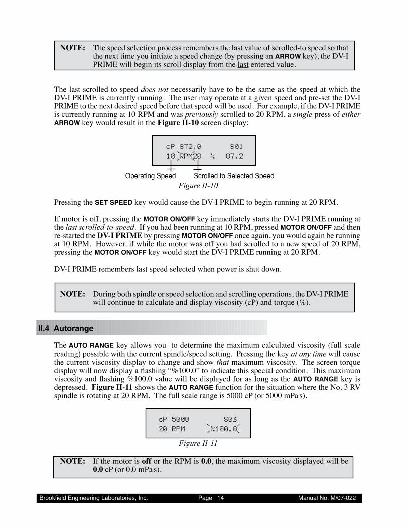
The last-scrolled-to speed does not necessarily have to be the same as the speed at which the DV-I PRIME is currently running. The user may operate at a given speed and pre-set the DV-I PRIME to the next desired speed before that speed will be used. For example, if the DV-I PRIME is currently running at 10 RPM and was previously scrolled to 20 RPM, a single press of either ARROW key would result in the Figure II-10 screen display:
cP872.0 S0110RPM20% 87.2
Scrolled to Selected Speed Operating SpeedFigure II-10
Pressing the SET SPEED key would cause the DV-I PRIME to begin running at 20 RPM.
If motor is off, pressing the MOTOR ON/OFF key immediately starts the DV-I PRIME running at the last scrolled-to-speed. If you had been running at 10 RPM, pressed MOTOR ON/OFF and then re-started the DV-I PRIME by pressing MOTOR ON/OFF once again, you would again be running at 10 RPM. However, if while the motor was off you had scrolled to a new speed of 20 RPM, pressing the MOTOR ON/OFF key would start the DV-I PRIME running at 20 RPM.
DV-I PRIME remembers last speed selected when power is shut down.
NOTE: During both spindle or speed selection and scrolling operations, the DV-I PRIME will continue to calculate and display viscosity (cP) and torque (%).
II.4 Autorange
The AUTO RANGE key allows you to determine the maximum calculated viscosity (full scale reading) possible with the current spindle/speed setting. Pressing the key at any time will cause the current viscosity display to change and show that maximum viscosity. The screen torque display will now display a flashing “%100.0” to indicate this special condition. This maximum viscosity and flashing %100.0 value will be displayed for as long as the AUTO RANGE key is depressed. Figure II-11 shows the AUTO RANGE function for the situation where the No. 3 RV spindle is rotating at 20 RPM. The full scale range is 5000 cP (or 5000 mPa.s).
cP5000 S0320RPM %100.0
Figure II-11
NOTE: If the motor is off or the RPM is 0.0, the maximum viscosity displayed will be 0.0 cP (or 0.0 mPa.s).
Brookfield Engineering Laboratories, Inc. Page �� Manual No. M/07-022
II.5 CGS or SI Units Selection
Pressing and holding the AUTO RANGE key during power on will enable the viscosity display to be read in either CGS or SI units. To change the unit format:
1. Turn the power off. 2. Press and hold the AUTO RANGE key and turn the power ON.
The DV-I PRIME will retain the unit selection when the viscometer is turned OFF.
CGS SIViscosity cP mPa•s
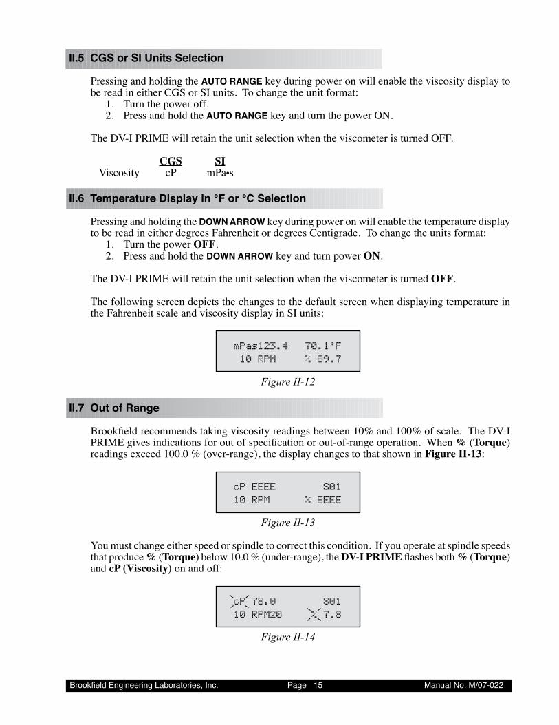
II.6 Temperature Display in °F or °C Selection
Pressing and holding the DOWN ARROW key during power on will enable the temperature display to be read in either degrees Fahrenheit or degrees Centigrade. To change the units format:
1. Turn the power OFF. 2. Press and hold the DOWN ARROW key and turn power ON.
The DV-I PRIME will retain the unit selection when the viscometer is turned OFF.
The following screen depicts the changes to the default screen when displaying temperature in the Fahrenheit scale and viscosity display in SI units:
mPas123.4 70.1°F10RPM %89.7
Figure II-12
II.7 Out of Range
Brookfield recommends taking viscosity readings between 10% and 100% of scale. The DV-I PRIME gives indications for out of specification or out-of-range operation. When % (Torque) readings exceed 100.0 % (over-range), the display changes to that shown in Figure II-13:
cPEEEE S0110RPM %EEEE
Figure II-13
You must change either speed or spindle to correct this condition. If you operate at spindle speeds that produce % (Torque) below 10.0 % (under-range), the DV-I PRIME flashes both % (Torque) and cP (Viscosity) on and off:
cP78.0 S0110RPM20 %7.8
Figure II-14
Brookfield Engineering Laboratories, Inc. Page �� Manual No. M/07-022
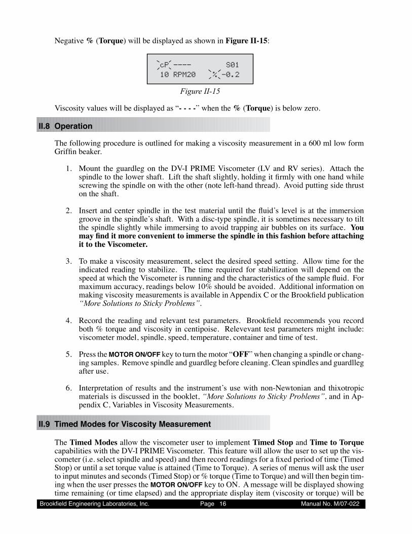
Negative % (Torque) will be displayed as shown in Figure II-15:
cP---- S0110RPM20 %-0.2
Figure II-15
Viscosity values will be displayed as “- - - -” when the % (Torque) is below zero.
II.8 Operation
The following procedure is outlined for making a viscosity measurement in a 600 ml low form Griffin beaker.
1. Mount the guardleg on the DV-I PRIME Viscometer (LV and RV series). Attach the spindle to the lower shaft. Lift the shaft slightly, holding it firmly with one hand while screwing the spindle on with the other (note left-hand thread). Avoid putting side thrust on the shaft.
2. Insert and center spindle in the test material until the fluid’s level is at the immersion groove in the spindle’s shaft. With a disc-type spindle, it is sometimes necessary to tilt the spindle slightly while immersing to avoid trapping air bubbles on its surface. You may find it more convenient to immerse the spindle in this fashion before attaching it to the Viscometer.
3. To make a viscosity measurement, select the desired speed setting. Allow time for the indicated reading to stabilize. The time required for stabilization will depend on the speed at which the Viscometer is running and the characteristics of the sample fluid. For maximum accuracy, readings below 10% should be avoided. Additional information on making viscosity measurements is available in Appendix C or the Brookfield publication “More Solutions to Sticky Problems”.
4. Record the reading and relevant test parameters. Brookfield recommends you record both % torque and viscosity in centipoise. Relevevant test parameters might include: viscometer model, spindle, speed, temperature, container and time of test.
5. Press the MOTOR ON/OFF key to turn the motor “OFF” when changing a spindle or chang-ing samples. Remove spindle and guardleg before cleaning. Clean spindles and guardlleg after use.
6. Interpretation of results and the instrument’s use with non-Newtonian and thixotropic materials is discussed in the booklet, “More Solutions to Sticky Problems”, and in Ap-pendix C, Variables in Viscosity Measurements.
II.9 Timed Modes for Viscosity Measurement
The Timed Modes allow the viscometer user to implement Timed Stop and Time to Torque capabilities with the DV-I PRIME Viscometer. This feature will allow the user to set up the vis-cometer (i.e. select spindle and speed) and then record readings for a fixed period of time (Timed Stop) or until a set torque value is attained (Time to Torque). A series of menus will ask the user to input minutes and seconds (Timed Stop) or % torque (Time to Torque) and will then begin tim-ing when the user presses the MOTOR ON/OFF key to ON. A message will be displayed showing time remaining (or time elapsed) and the appropriate display item (viscosity or torque) will be
Brookfield Engineering Laboratories, Inc. Page �7 Manual No. M/07-022
updated continuously during the event. Upon completion, the viscometer will display a screen stating that the test is complete and will also display the final recorded value for the viscosity in the first case, and the time in minutes and seconds to reach the torque limit in the second case.
II.9.1 Set Up
1. The user must pre-select the display unit option: CGS or SI. (see II.5)
2. The user then selects (via the UP and DOWN arrows) the spindle speed. (see II.3)
NOTE: If 0.0 RPM is the selected speed setting (the default after executing AUTOZERO) the timed modes can be executed; however, the results will be meaningless show-ing no viscosity values.
3. Next, the user selects the spindle number corresponding to the spindle attached.
4. Now, the user presses the MOTOR ON/OFF key to ensure that the motor is OFF. Setting the motor to the OFF condition sets up the viscometer for executing the Timed Modes.
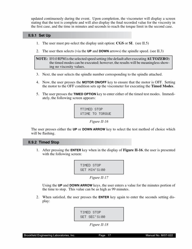
5. The user presses the TIMED OPTION key to enter either of the timed test modes. Immedi-ately, the following screen appears:
èTIMEDSTOPêTIMETOTORQUE
Figure II-16
The user presses either the UP or DOWN ARROW key to select the test method of choice which will be flashing.
II.9.2 Timed Stop
1. After pressing the ENTER key when in the display of Figure II-16, the user is presented with the following screen:
TIMEDSTOPSETMIN’S:00
Figure II-17
Using the UP and DOWN ARROW keys, the user enters a value for the minutes portion of the time to stop. This value can be as high as 99 minutes.
2. When satisfied, the user presses the ENTER key again to enter the seconds setting dis-play:
TIMEDSTOPSETSEC’S:00
Figure II-18
Brookfield Engineering Laboratories, Inc. Page �� Manual No. M/07-022
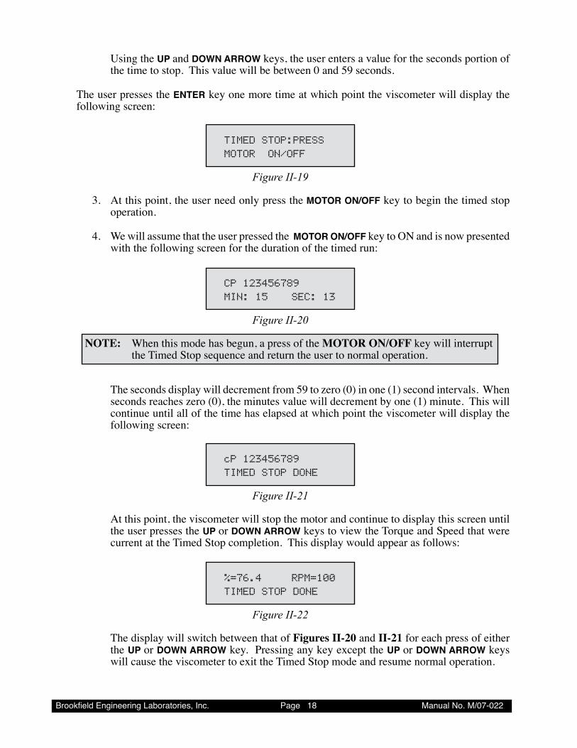
Using the UP and DOWN ARROW keys, the user enters a value for the seconds portion of the time to stop. This value will be between 0 and 59 seconds.
The user presses the ENTER key one more time at which point the viscometer will display the following screen:
TIMEDSTOP:PRESSMOTORON/OFF
Figure II-19
3. At this point, the user need only press the MOTOR ON/OFF key to begin the timed stop operation.
4. We will assume that the user pressed the MOTOR ON/OFF key to ON and is now presented with the following screen for the duration of the timed run:
CP123456789MIN:15 SEC:13
Figure II-20
NOTE: When this mode has begun, a press of the MOTOR ON/OFF key will interrupt the Timed Stop sequence and return the user to normal operation.
The seconds display will decrement from 59 to zero (0) in one (1) second intervals. When seconds reaches zero (0), the minutes value will decrement by one (1) minute. This will continue until all of the time has elapsed at which point the viscometer will display the following screen:
cP123456789TIMEDSTOPDONE
Figure II-21
At this point, the viscometer will stop the motor and continue to display this screen until the user presses the UP or DOWN ARROW keys to view the Torque and Speed that were current at the Timed Stop completion. This display would appear as follows:
%=76.4 RPM=100TIMEDSTOPDONE
Figure II-22
The display will switch between that of Figures II-20 and II-21 for each press of either the UP or DOWN ARROW key. Pressing any key except the UP or DOWN ARROW keys will cause the viscometer to exit the Timed Stop mode and resume normal operation.
Brookfield Engineering Laboratories, Inc. Page �� Manual No. M/07-022
NOTE: For the Timed Stop method, the DV-I PRIME Viscometer will retain the last value for the time interval in MEMORY so that it will become the default the next time the user elects to use this method.
II.9.3 Time to Torque
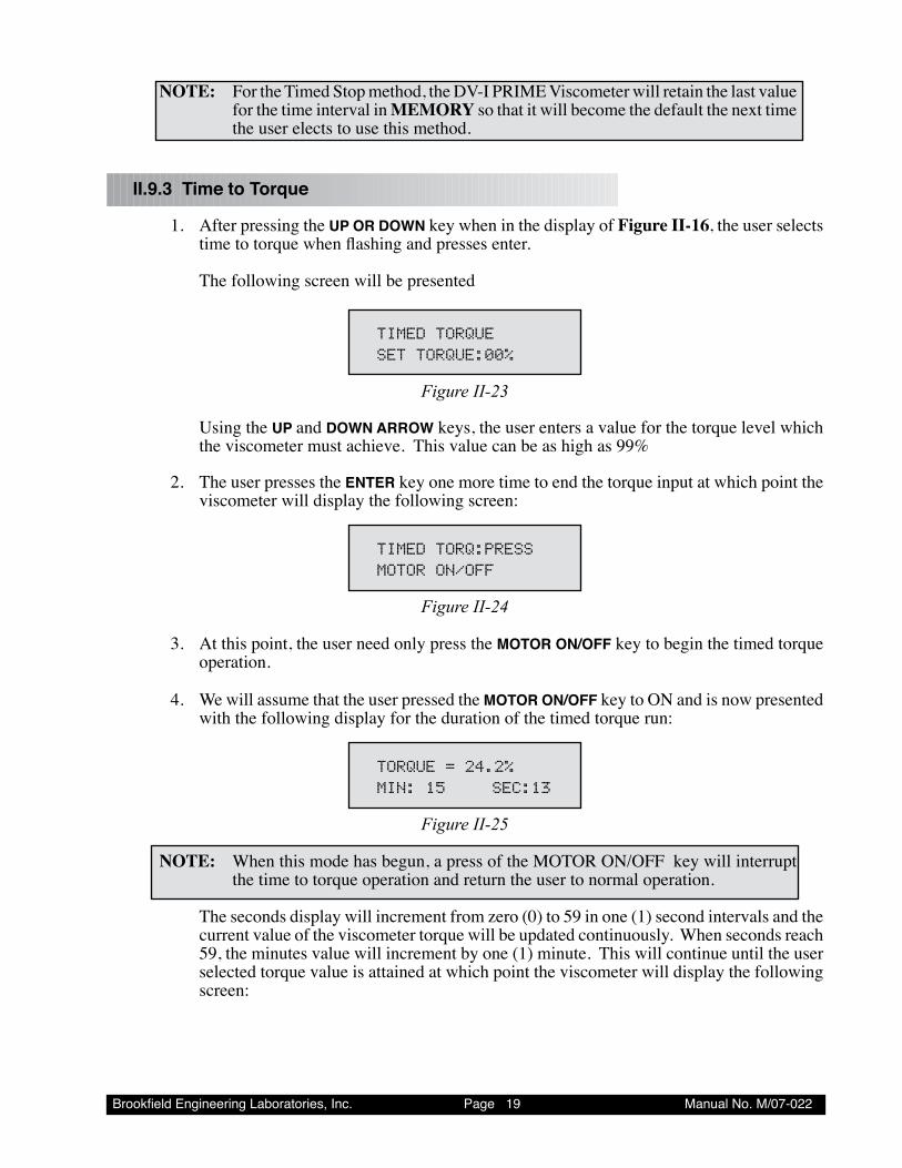
1. After pressing the UP OR DOWN key when in the display of Figure II-16, the user selects time to torque when flashing and presses enter.
The following screen will be presented
TIMEDTORQUESETTORQUE:00%
Figure II-23
Using the UP and DOWN ARROW keys, the user enters a value for the torque level which the viscometer must achieve. This value can be as high as 99%
2. The user presses the ENTER key one more time to end the torque input at which point the viscometer will display the following screen:
TIMEDTORQ:PRESSMOTORON/OFF
Figure II-24
3. At this point, the user need only press the MOTOR ON/OFF key to begin the timed torque operation.
4. We will assume that the user pressed the MOTOR ON/OFF key to ON and is now presented with the following display for the duration of the timed torque run:
TORQUE=24.2%MIN:15 SEC:13
Figure II-25
NOTE: When this mode has begun, a press of the MOTOR ON/OFF key will interrupt the time to torque operation and return the user to normal operation.
The seconds display will increment from zero (0) to 59 in one (1) second intervals and the current value of the viscometer torque will be updated continuously. When seconds reach 59, the minutes value will increment by one (1) minute. This will continue until the user selected torque value is attained at which point the viscometer will display the following screen:
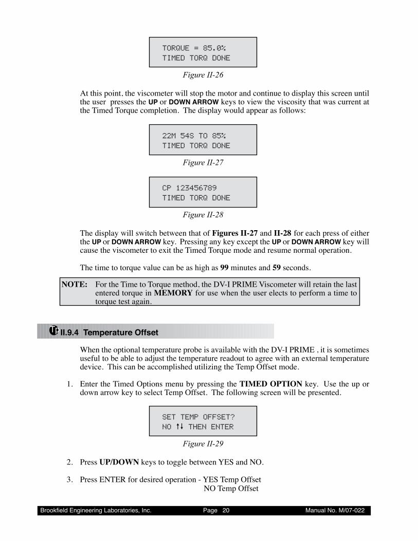
Brookfield Engineering Laboratories, Inc. Page 20 Manual No. M/07-022
TORQUE=85.0%TIMEDTORQDONE
Figure II-26
At this point, the viscometer will stop the motor and continue to display this screen until the user presses the UP or DOWN ARROW keys to view the viscosity that was current at the Timed Torque completion. The display would appear as follows:
22M54STO85%TIMEDTORQDONE
Figure II-27
CP123456789TIMEDTORQDONE
Figure II-28
The display will switch between that of Figures II-27 and II-28 for each press of either the UP or DOWN ARROW key. Pressing any key except the UP or DOWN ARROW key will cause the viscometer to exit the Timed Torque mode and resume normal operation.
The time to torque value can be as high as 99 minutes and 59 seconds.
NOTE: For the Time to Torque method, the DV-I PRIME Viscometer will retain the last entered torque in MEMORY for use when the user elects to perform a time to torque test again.
Tp II.9.4 Temperature Offset
When the optional temperature probe is available with the DV-I PRIME , it is sometimes useful to be able to adjust the temperature readout to agree with an external temperature device. This can be accomplished utilizing the Temp Offset mode.
1. Enter the Timed Options menu by pressing the TIMED OPTION key. Use the up or down arrow key to select Temp Offset. The following screen will be presented.
SETTEMPOFFSET?NOèêTHENENTER
Figure II-29
2. Press UP/DOWN keys to toggle between YES and NO.
3. Press ENTER for desired operation - YES Temp Offset NO Temp Offset
Brookfield Engineering Laboratories, Inc. Page 2� Manual No. M/07-022
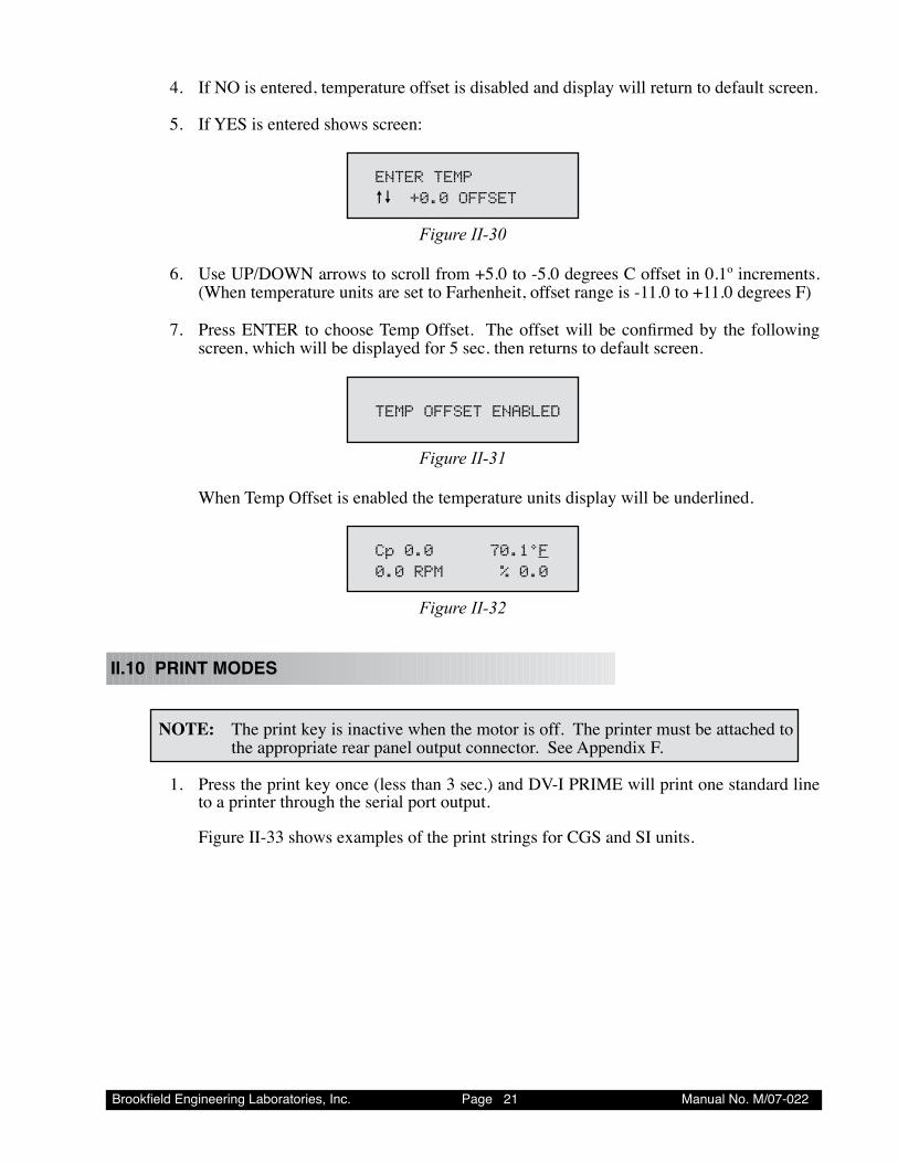
4. If NO is entered, temperature offset is disabled and display will return to default screen. 5. If YES is entered shows screen:
ENTERTEMPèê +0.0OFFSET
Figure II-30
6. Use UP/DOWN arrows to scroll from +5.0 to -5.0 degrees C offset in 0.1º increments. (When temperature units are set to Farhenheit, offset range is -11.0 to +11.0 degrees F)
7. Press ENTER to choose Temp Offset. The offset will be confirmed by the following screen, which will be displayed for 5 sec. then returns to default screen.
TEMPOFFSETENABLED
Figure II-31
When Temp Offset is enabled the temperature units display will be underlined.
Cp0.0 70.1°F0.0RPM %0.0
Figure II-32
II.10 PRINT MODES
NOTE: The print key is inactive when the motor is off. The printer must be attached to the appropriate rear panel output connector. See Appendix F.
1. Press the print key once (less than 3 sec.) and DV-I PRIME will print one standard line to a printer through the serial port output.
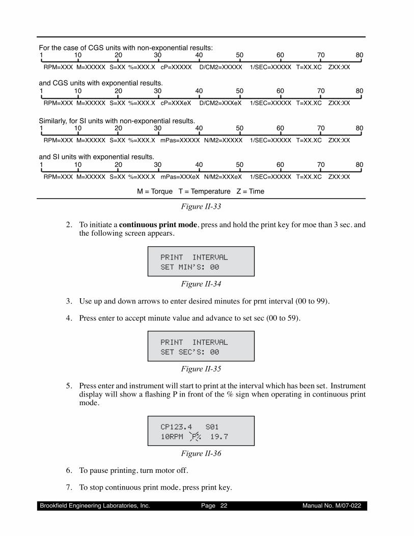
Figure II-33 shows examples of the print strings for CGS and SI units.
Brookfield Engineering Laboratories, Inc. Page 22 Manual No. M/07-022
For the case of CGS units with non-exponential results:
and CGS units with exponential results.
Similarly, for SI units with non-exponential results.
and SI units with exponential results.
M = Torque T = Temperature Z = Time
1 10 20 30 40 50 60 70 80
RPM=XXX M=XXXXX S=XX %=XXX.X cP=XXXXX D/CM2=XXXXX 1/SEC=XXXXX T=XX.XC ZXX:XX
RPM=XXX M=XXXXX S=XX %=XXX.X cP=XXXeX D/CM2=XXXeX 1/SEC=XXXXX T=XX.XC ZXX:XX
1 10 20 30 40 50 60 70 80
RPM=XXX M=XXXXX S=XX %=XXX.X mPas=XXXXX N/M2=XXXXX 1/SEC=XXXXX T=XX.XC ZXX:XX
1 10 20 30 40 50 60 70 80
1 10 20 30 40 50 60 70 80
RPM=XXX M=XXXXX S=XX %=XXX.X mPas=XXXeX N/M2=XXXeX 1/SEC=XXXXX T=XX.XC ZXX:XX
Figure II-33
2. To initiate a continuous print mode, press and hold the print key for moe than 3 sec. and the following screen appears.
PRINTINTERVALSETMIN’S:00
Figure II-34
3. Use up and down arrows to enter desired minutes for prnt interval (00 to 99).
4. Press enter to accept minute value and advance to set sec (00 to 59).
PRINTINTERVALSETSEC’S:00
Figure II-35
5. Press enter and instrument will start to print at the interval which has been set. Instrument display will show a flashing P in front of the % sign when operating in continuous print mode.
CP123.4S0110RPMP%19.7
Figure II-36
6. To pause printing, turn motor off.
7. To stop continuous print mode, press print key.
Brookfield Engineering Laboratories, Inc. Page 2� Manual No. M/07-022
II.11 COMMUNICATION WITH WINGATHER SOFTWARE
The DV-I PRIME can be used in conjunction with the Brookfield software program Wingather. Wingather will collect the data output from the DV-I PRIME and allow for; data storage, data printing, graphing, and mathematical analysis.
NOTE: Wingather must be version 3.0 or higher for use with DV-I PRIME. The DV-I Prime must be set to continuous print mode for proper communication to Wingather (Refer to section II.10 for instruction). Set the print interval to 00MIN and 01SEC. Data collection modes are detailed in the Wingather Help files. All test controls will remain at the DV-I PRIME (spindle selection, speed selection, speed change). The communication cable for connecting the DV-I PRIME to the computer is supplied with the Wingather software (part number DVP-80). Appendix F provides detail regarding the communication cable.
Brookfield Engineering Laboratories, Inc. Page 2� Manual No. M/07-022
III. MAKING VISCOSITY MEASUREMENTS
III.1 Quick Start
Viscosity Measurement
The DV-I PRIME Viscometer uses the same methodology for viscosity measurement as the Brookfield Dial Reading Viscometer and DV series of Digital Viscometers. If you have experience with other Brookfield equipment, this section will give you the quick steps for taking a viscosity reading. If you have not used a Brookfield Viscometer before, skip this section and go to Section III.2 for a detailed description.
A) Assemble and level the viscometer (Section I.4).
B) Autozero the viscometer (Section II.1).
C) Enter the spindle number using the SELECT SPINDLE key (Section II.2).
D) Introduce the spindle into the sample and attach the spindle to the coupling nut. NOTE: Left-hand threads.
E) Enter the speed of rotation using the ARROW KEYS and SET SPEED key (Section 11.3).
F) Record % torque and viscosity.
III.2 Preparations for Making Measurements
A) VISCOMETER: The DV-I PRIME should be turned on, leveled and autozeroed. The level is adjusted using the three feet on the bottom of the base and confirmed using the bubble on the top of the head. Adjust the feet until bubble is inside the center target. Set the level prior to autozero and check the level prior to each measurement.
Proper level is essential for correct operation of the DV-I PRIME.
B) SAMPLE: The fluid to be measured (sample) must be in a container. The standard spindles supplied with the DV-I PRIME (LV(1-4), RV(2-7), or HA/HB(2-7)) are designed to be used with a 600 mL low form Griffin beaker (or equivalent container with a diameter of 8.25cm). The same applies to the optional RV1, HA/HB1. Many other spindle systems are supplied from Brookfield with specific sample chambers such as the Small Sample Adapter, UL Adapter and Thermosel.
Brookfield recommends that you use the appropriate container for the selected spindle. You may choose to use an alternate container for convenience, however, this may have an effect on the measured viscosity. The DV-I PRIME is calibrated considering the specified container. Alternate containers will provide results that are repeatable but not "true."
The LV (1-4) and RV (1-7) are designed to be used with the guardleg attached. Measure-
Brookfield Engineering Laboratories, Inc. Page 2� Manual No. M/07-022
ments made without the guardleg will provide repeatable results but may not provide "true" results.
When comparing data with others, be sure to specify the sample container and pres-ence/absence of the guardleg.
Many samples must be controlled to a specific temperature for viscosity measurement. When conditioning a sample for temperature, be sure to temperature control the container and spindle as well as the sample.
Please see our publication, "More Solutions to Sticky Problems", for more detail relating to sample preparation.
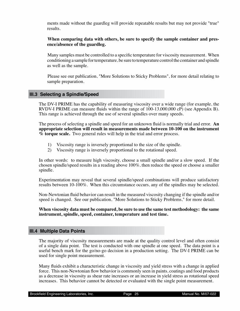
III.3 Selecting a Spindle/Speed
The DV-I PRIME has the capability of measuring viscosity over a wide range (for example, the RVDV-I PRIME can measure fluids within the range of 100-13,000,000 cP) (see Appendix B). This range is achieved through the use of several spindles over many speeds.
The process of selecting a spindle and speed for an unknown fluid is normally trial and error. An appropriate selection will result in measurements made between 10-100 on the instrument % torque scale. Two general rules will help in the trial and error process.
1) Viscosity range is inversely proportional to the size of the spindle. 2) Viscosity range is inversely proportional to the rotational speed.
In other words: to measure high viscosity, choose a small spindle and/or a slow speed. If the chosen spindle/speed results in a reading above 100%, then reduce the speed or choose a smaller spindle.
Experimentation may reveal that several spindle/speed combinations will produce satisfactory results between 10-100%. When this circumstance occurs, any of the spindles may be selected.
Non-Newtonian fluid behavior can result in the measured viscosity changing if the spindle and/or speed is changed. See our publication, "More Solutions to Sticky Problems," for more detail.
When viscosity data must be compared, be sure to use the same test methodology: the same instrument, spindle, speed, container, temperature and test time.
III.4 Multiple Data Points
The majority of viscosity measurements are made at the quality control level and often consist of a single data point. The test is conducted with one spindle at one speed. The data point is a useful bench mark for the go/no-go decision in a production setting. The DV-I PRIME can be used for single point measurement.
Many fluids exhibit a characteristic change in viscosity and yield stress with a change in applied force. This non-Newtonian flow behavior is commonly seen in paints, coatings and food products as a decrease in viscosity as shear rate increases or an increase in yield stress as rotational speed increases. This behavior cannot be detected or evaluated with the single point measurement.

Brookfield Engineering Laboratories, Inc. Page 2� Manual No. M/07-022
Non-Newtonian flow is analyzed through the collection of viscosity data over a range of shear rates and the generation of a graph of viscosity versus shear rate (a rheogram). This information will allow for a more complete characterization of a fluid and may help in formulating and production of the product. The DV-I PRIME is capable of collecting multiple data points for comprehensive analysis of flow behavior. Wingather Software can be used for this type of analysis.
More information on flow behavior, shear rate and rheograms is available in our publication, "More Solutions to Sticky Problems."
Brookfield Engineering Laboratories, Inc. Page 27 Manual No. M/07-022
Appendix A - Cone/Plate Viscometer Set-Up This Cone/Plate version of the DV-I PRIME uses the same operating instruction procedures as described in this manual. However, the “gap” between the cone and the plate must be verified/adjusted before measurements are made. This is done by moving the plate (built into the sample cup) up towards the cone until the pin in the center of the cone touches the surface of the plate, and then by separating (lowering) the plate 0.0005 inch (0.013mm).
DV-I PRIME Cone/Plate Viscometers have an Electronic Gap Setting feature. This feature en-ables the user to easily find the 0.0005 inch gap setting that was established at Brookfield prior to shipment.
The following information explains how to set the Electronic Gap and verify calibration of the DV-I PRIME Viscometer.
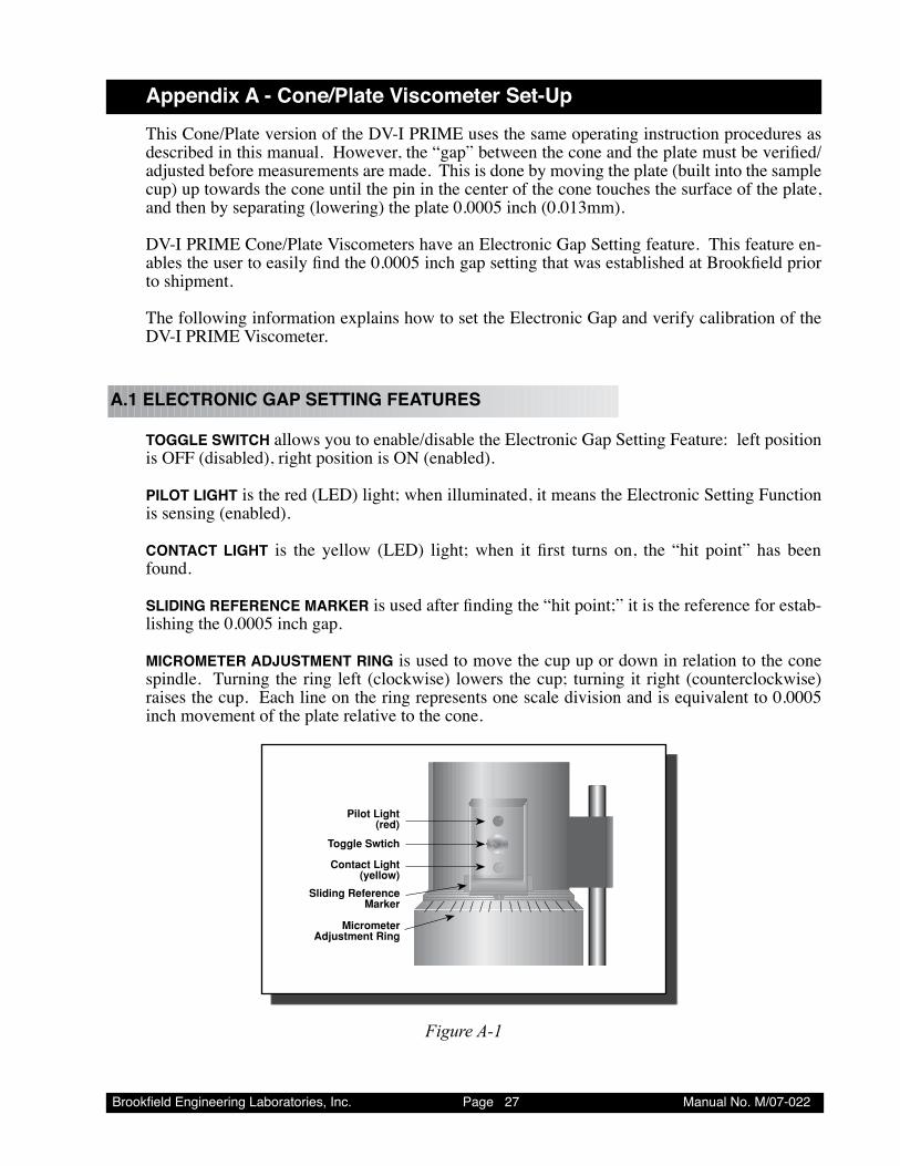
A.1 ELECTRONIC GAP SETTING FEATURES
TOGGLE SWITCH allows you to enable/disable the Electronic Gap Setting Feature: left position is OFF (disabled), right position is ON (enabled).
PILOT LIGHT is the red (LED) light; when illuminated, it means the Electronic Setting Function is sensing (enabled).
CONTACT LIGHT is the yellow (LED) light; when it first turns on, the “hit point” has been found.
SLIDING REFERENCE MARKER is used after finding the “hit point;” it is the reference for estab-lishing the 0.0005 inch gap.
MICROMETER ADJUSTMENT RING is used to move the cup up or down in relation to the cone spindle. Turning the ring left (clockwise) lowers the cup; turning it right (counterclockwise) raises the cup. Each line on the ring represents one scale division and is equivalent to 0.0005 inch movement of the plate relative to the cone.
Pilot Light(red)
Toggle Swtich
Contact Light(yellow)
Sliding ReferenceMarker
MicrometerAdjustment Ring
Figure A-1
Brookfield Engineering Laboratories, Inc. Page 2� Manual No. M/07-022
SampleCup
(CPE-44Yor
CPE-44PY)
Bath/Circulator
BathInlet
BathOutlet
CupOutlet
CupInlet
MicrometerRing
Figure A-3
SpindleWrench
(CPE) Cone
These surfacesmust be clean!
Coupling Nut
MicrometerAdjustment
Ring
Do Not hit theCONE with the CUP!
Figure A-4
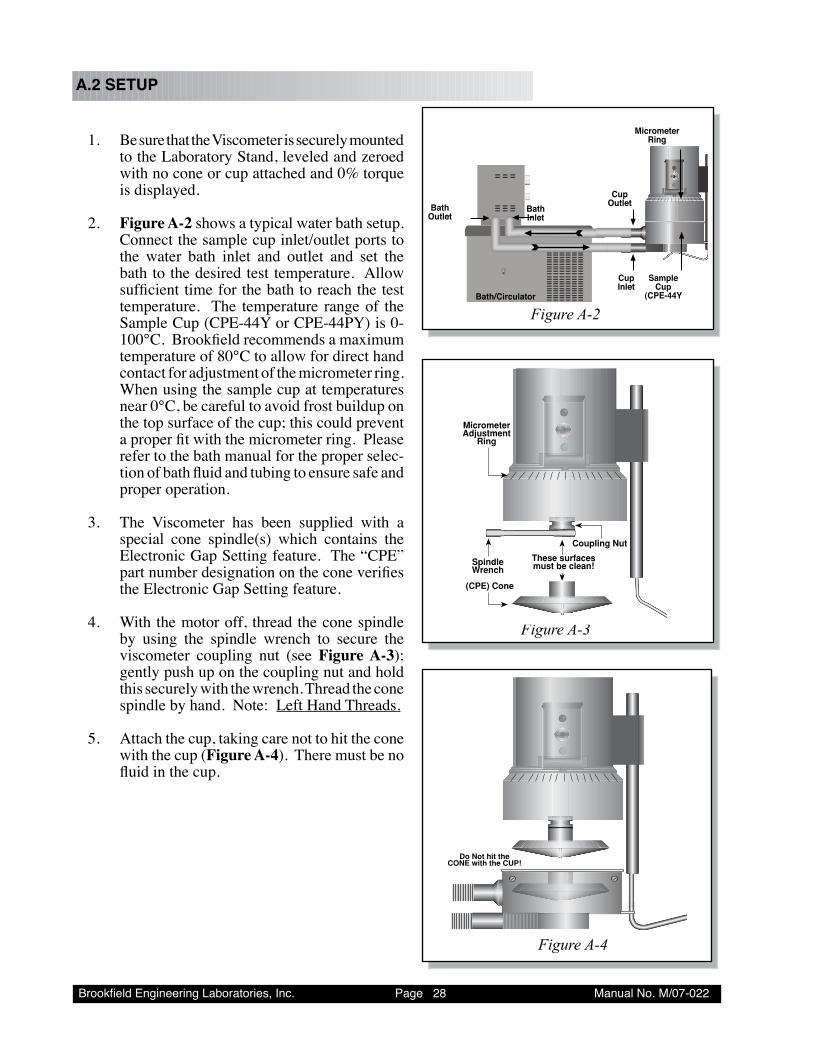
A.2 SETUP
1. Be sure that the Viscometer is securely mounted to the Laboratory Stand, leveled and zeroed with no cone or cup attached and 0% torque is displayed.
2. Figure A-2 shows a typical water bath setup. Connect the sample cup inlet/outlet ports to the water bath inlet and outlet and set the bath to the desired test temperature. Allow sufficient time for the bath to reach the test temperature. The temperature range of the Sample Cup (CPE-44Y or CPE-44PY) is 0-100°C. Brookfield recommends a maximum temperature of 80°C to allow for direct hand contact for adjustment of the micrometer ring. When using the sample cup at temperatures near 0°C, be careful to avoid frost buildup on the top surface of the cup; this could prevent a proper fit with the micrometer ring. Please refer to the bath manual for the proper selec-tion of bath fluid and tubing to ensure safe and proper operation.
3. The Viscometer has been supplied with a special cone spindle(s) which contains the Electronic Gap Setting feature. The “CPE” part number designation on the cone verifies the Electronic Gap Setting feature.
4. With the motor off, thread the cone spindle by using the spindle wrench to secure the viscometer coupling nut (see Figure A-3); gently push up on the coupling nut and hold this securely with the wrench. Thread the cone spindle by hand. Note: Left Hand Threads.
5. Attach the cup, taking care not to hit the cone with the cup (Figure A-4). There must be no fluid in the cup.
Figure A-2
Brookfield Engineering Laboratories, Inc. Page 2� Manual No. M/07-022
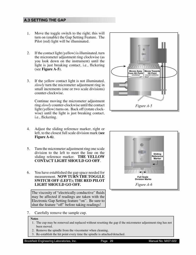
A.3 SETTING THE GAP
1. Move the toggle switch to the right; this will turn on (enable) the Gap Setting Feature. The Pilot (red) light will be illuminated.
2. If the contact light (yellow) is illuminated, turn the micrometer adjustment ring clockwise (as you look down on the instrument) until the light is just breaking contact, i.e., flickering (see Figure A-5).
3. If the yellow contact light is not illuminated, slowly turn the micrometer adjustment ring in small increments (one or two scale divisions) counter-clockwise.
Continue moving the micrometer adjustment ring slowly counter-clockwise until the contact light (yellow) turns on. Back off (rotate clock-wise) until the light is just breaking contact, i.e., flickering.
4. Adjust the sliding reference marker, right or left, to the closest full scale division mark (see Figure A-6).
5. Turn the micrometer adjustment ring one scale division to the left to meet the line on the sliding reference marker. THE YELLOW CONTACT LIGHT SHOULD GO OFF.
6. You have established the gap space needed for measurement. NOW TURN THE TOGGLE SWITCH OFF (LEFT); THE RED PILOT LIGHT SHOULD GO OFF.
The viscosity of “electrically conductive” fluids may be affected if readings are taken with the Electronic Gap Setting feature “on”. Be sure to shut the feature “off” before taking readings!
7. Carefully remove the sample cup.
Moves Awayfrom Hit Point
(clockwise) LEFTx
Moves Towards Hit Point
(counter-clockwise) RIGHT
Full Scale Division Marks
SlidingReference
Marker
Figure A-5
Figure A-6
Notes1. The cup may be removed and replaced without resetting the gap if the micrometer adjustment ring has not
been moved.2. Remove the spindle from the viscometer when cleaning.3. Re-establish the hit point every time the spindle is attached/detached.
Brookfield Engineering Laboratories, Inc. Page �0 Manual No. M/07-022
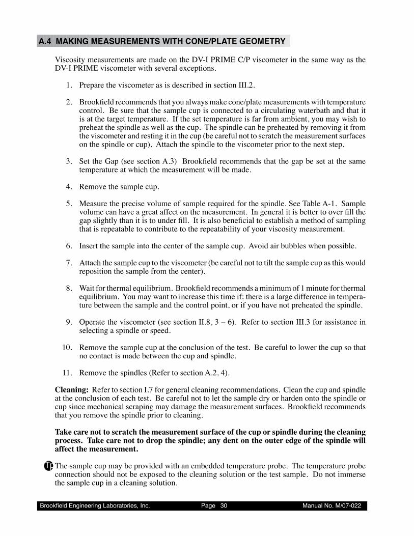
A.4 MAKING MEASUREMENTS WITH CONE/PLATE GEOMETRY
Viscosity measurements are made on the DV-I PRIME C/P viscometer in the same way as the DV-I PRIME viscometer with several exceptions.
1. Prepare the viscometer as is described in section III.2.
2. Brookfield recommends that you always make cone/plate measurements with temperature control. Be sure that the sample cup is connected to a circulating waterbath and that it is at the target temperature. If the set temperature is far from ambient, you may wish to preheat the spindle as well as the cup. The spindle can be preheated by removing it from the viscometer and resting it in the cup (be careful not to scratch the measurement surfaces on the spindle or cup). Attach the spindle to the viscometer prior to the next step.
3. Set the Gap (see section A.3) Brookfield recommends that the gap be set at the same temperature at which the measurement will be made.
4. Remove the sample cup.
5. Measure the precise volume of sample required for the spindle. See Table A-1. Sample volume can have a great affect on the measurement. In general it is better to over fill the gap slightly than it is to under fill. It is also beneficial to establish a method of sampling that is repeatable to contribute to the repeatability of your viscosity measurement.
6. Insert the sample into the center of the sample cup. Avoid air bubbles when possible. 7. Attach the sample cup to the viscometer (be careful not to tilt the sample cup as this would
reposition the sample from the center).
8. Wait for thermal equilibrium. Brookfield recommends a minimum of 1 minute for thermal equilibrium. You may want to increase this time if; there is a large difference in tempera-ture between the sample and the control point, or if you have not preheated the spindle.
9. Operate the viscometer (see section II.8, 3 – 6). Refer to section III.3 for assistance in selecting a spindle or speed.
10. Remove the sample cup at the conclusion of the test. Be careful to lower the cup so that no contact is made between the cup and spindle.
11. Remove the spindles (Refer to section A.2, 4).
Cleaning: Refer to section I.7 for general cleaning recommendations. Clean the cup and spindle at the conclusion of each test. Be careful not to let the sample dry or harden onto the spindle or cup since mechanical scraping may damage the measurement surfaces. Brookfield recommends that you remove the spindle prior to cleaning. Take care not to scratch the measurement surface of the cup or spindle during the cleaning process. Take care not to drop the spindle; any dent on the outer edge of the spindle will affect the measurement. The sample cup may be provided with an embedded temperature probe. The temperature probe connection should not be exposed to the cleaning solution or the test sample. Do not immerse the sample cup in a cleaning solution.
Tp
Brookfield Engineering Laboratories, Inc. Page �� Manual No. M/07-022
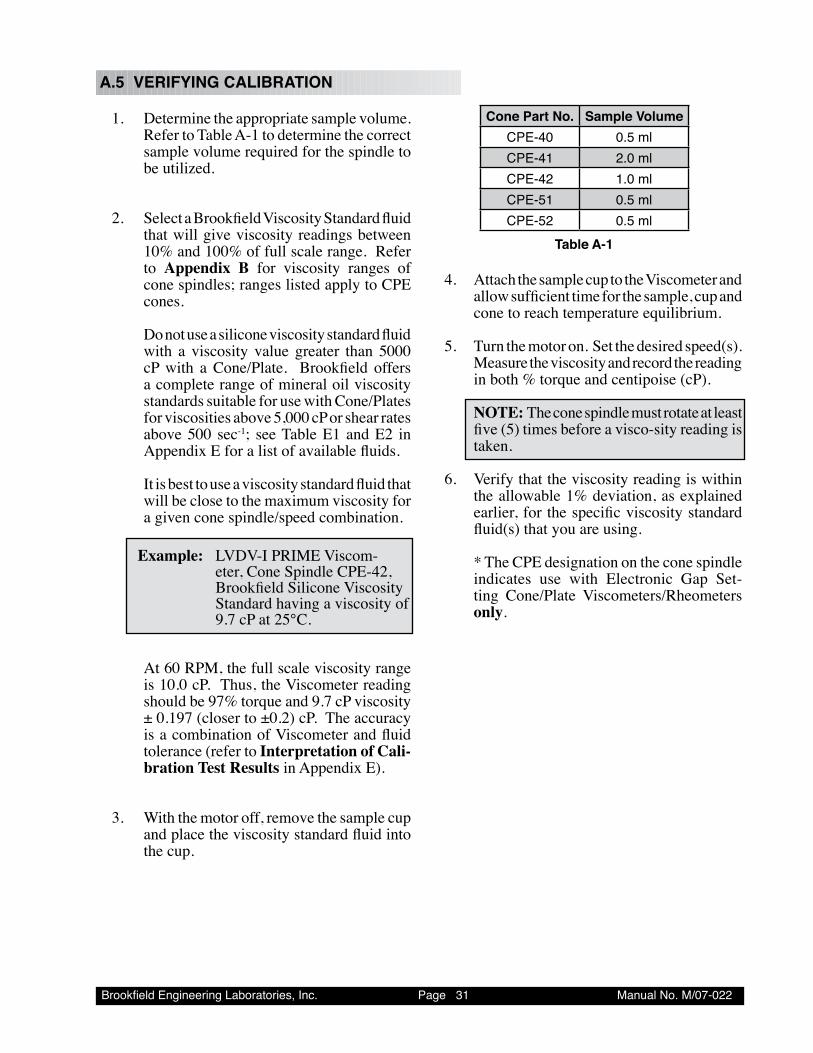
Cone Part No. Sample VolumeCPE-�0 0.� mlCPE-�� 2.0 mlCPE-�2 �.0 mlCPE-�� 0.� mlCPE-�2 0.� ml
Table A-1
4. Attach the sample cup to the Viscometer and allow sufficient time for the sample, cup and cone to reach temperature equilibrium.
5. Turn the motor on. Set the desired speed(s).
Measure the viscosity and record the reading in both % torque and centipoise (cP).
NOTE: The cone spindle must rotate at least five (5) times before a visco-sity reading is taken.
6. Verify that the viscosity reading is within the allowable 1% deviation, as explained earlier, for the specific viscosity standard fluid(s) that you are using.
* The CPE designation on the cone spindle indicates use with Electronic Gap Set-ting Cone/Plate Viscometers/Rheometers only.
A.5 VERIFYING CALIBRATION
1. Determine the appropriate sample volume. Refer to Table A-1 to determine the correct sample volume required for the spindle to be utilized.
2. Select a Brookfield Viscosity Standard fluid that will give viscosity readings between 10% and 100% of full scale range. Refer to Appendix B for viscosity ranges of cone spindles; ranges listed apply to CPE cones.
Do not use a silicone viscosity standard fluid with a viscosity value greater than 5000 cP with a Cone/Plate. Brookfield offers a complete range of mineral oil viscosity standards suitable for use with Cone/Plates for viscosities above 5,000 cP or shear rates above 500 sec-1; see Table E1 and E2 in Appendix E for a list of available fluids.
It is best to use a viscosity standard fluid that will be close to the maximum viscosity for a given cone spindle/speed combination.
Example: LVDV-I PRIME Viscom-eter, Cone Spindle CPE-42, Brookfield Silicone Viscosity Standard having a viscosity of 9.7 cP at 25°C.
At 60 RPM, the full scale viscosity range is 10.0 cP. Thus, the Viscometer reading should be 97% torque and 9.7 cP viscosity ± 0.197 (closer to ±0.2) cP. The accuracy is a combination of Viscometer and fluid tolerance (refer to Interpretation of Cali-bration Test Results in Appendix E).
3. With the motor off, remove the sample cup and place the viscosity standard fluid into the cup.
Brookfield Engineering Laboratories, Inc. Page �2 Manual No. M/07-022
Appendix B - Viscosity Ranges
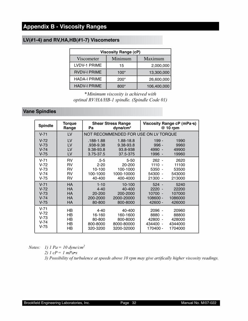
LV(#1-4) and RV,HA,HB(#1-7) Viscometers
Viscosity Range (cP)Viscometer Minimum Maximum
LVDV-� PRIME �� 2,000,000RVDV-I PRIME �00* ��,�00,000HADA-I PRIME 200* 2�,�00,000HADV-I PRIME �00* �0�,�00,000
*Minimum viscosity is achieved with optinal RV/HA/HB-1 spindle. (Spindle Code 01)
Vane Spindles
Spindle Torque Range
Shear Stress Range Pa dyne/cm2
Viscosity Range cP (mPa•s) @ 10 rpm
V-7� LV NOT RECOMMENDED FOR USE ON LV TORQUEV-72V-7�V-7�V-7�
LVLVLVLV
.���-�.�� �.��-��.� .���-�.�� �.��-��.� �.��-��.� ��.�-��� �.7�-�7.� �7.�-�7�
��� - ���0 ��� - ���0 ���0 - ���00 ���� - ����0
V-7�V-72V-7�V-7�V-7�
RVRVRVRVRV
.�-� �-�0 2-20 20-200 �0-�00 �00-�000 �00-�000 �000-�0000 �0-�00 �00-�000
2�2 - 2�20 ���0 - ���00 ���0 - ���00 ���00 - ���000 2��00 - 2��000
V-7�V-72V-7�V-7�V-7�
HAHAHAHAHA
�-�0 �0-�00 �-�0 �0-�00 20-200 200-2000 200-2000 2000-20000 �0-�00 �00-�000
�2� - �2�0 2220 - 22200 �0700 - �07000 �0��00 - �0��000 �2�00 - �2�000
V-7�V-72V-7�V-7�V-7�
HBHBHBHBHB
�-�0 �0-�00 ��-��0 ��0-��00 �0-�00 �00-�000 �00-�000 �000-�0000 �20-�200 �200-�2000
20�� - 20��0 ���0 - ���00 �2�00 - �2�000 ����00 - ����000 �70�00 - �70�000
Notes: 1) 1 Pa = 10 dyne/cm2
2) 1 cP = 1 mPa•s 3)Possibilityofturbulenceatspeedsabove10rpmmaygiveartificallyhigherviscosityreadings.
Brookfield Engineering Laboratories, Inc. Page �� Manual No. M/07-022
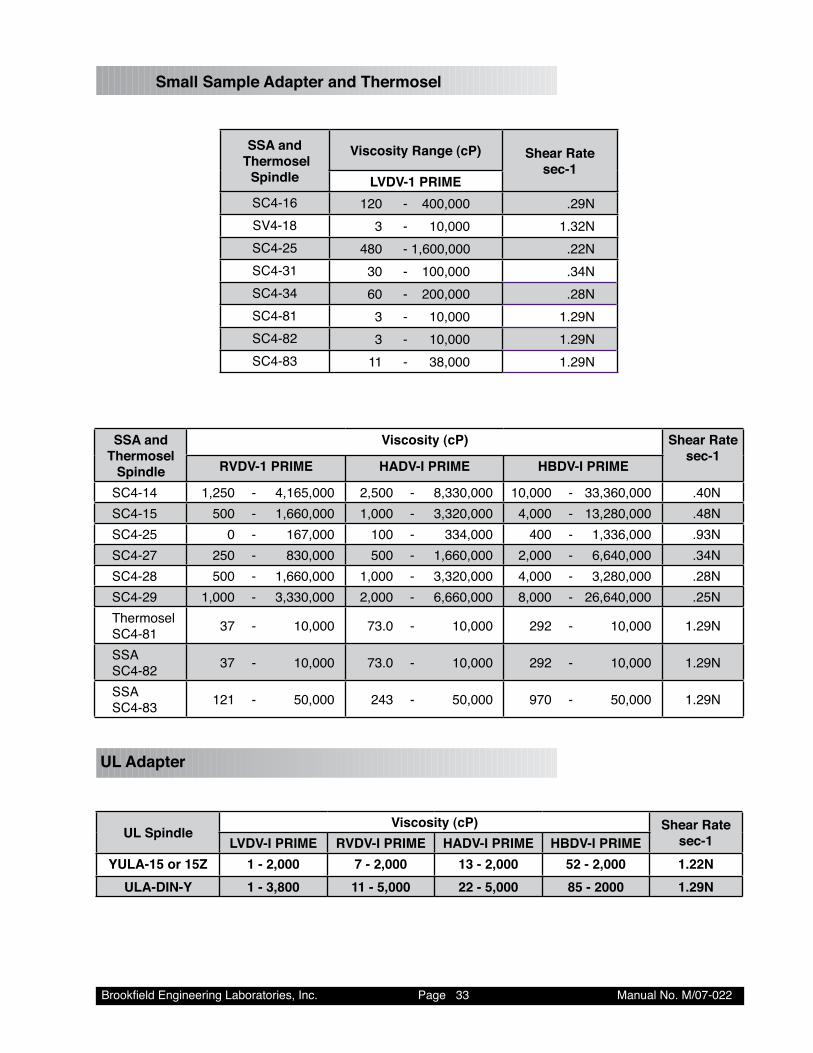
Small Sample Adapter and Thermosel
SSA and Thermosel
Spindle
Viscosity Range (cP) Shear Rate sec-1
LVDV-1 PRIMESC�-�� �20 - �00,000 .2�NSV�-�� � - �0,000 �.�2NSC�-2� ��0 - �,�00,000 .22NSC�-�� �0 - �00,000 .��NSC�-�� �0 - 200,000 .2�NSC�-�� � - �0,000 �.2�NSC�-�2 � - �0,000 �.2�NSC�-�� �� - ��,000 �.2�N
SSA and Thermosel
Spindle
Viscosity (cP) Shear Rate sec-1
RVDV-1 PRIME HADV-I PRIME HBDV-I PRIME
SC�-�� �,2�0 - �,���,000 2,�00 - �,��0,000 �0,000 - ��,��0,000 .�0NSC�-�� �00 - �,��0,000 �,000 - �,�20,000 �,000 - ��,2�0,000 .��NSC�-2� 0 - ��7,000 �00 - ���,000 �00 - �,���,000 .��NSC�-27 2�0 - ��0,000 �00 - �,��0,000 2,000 - �,��0,000 .��NSC�-2� �00 - �,��0,000 �,000 - �,�20,000 �,000 - �,2�0,000 .2�NSC�-2� �,000 - �,��0,000 2,000 - �,��0,000 �,000 - 2�,��0,000 .2�NThermoselSC�-�� �7 - �0,000 7�.0 - �0,000 2�2 - �0,000 �.2�N
SSASC�-�2 �7 - �0,000 7�.0 - �0,000 2�2 - �0,000 �.2�N
SSASC�-�� �2� - �0,000 2�� - �0,000 �70 - �0,000 �.2�N
UL Adapter
UL SpindleViscosity (cP) Shear Rate
sec-1LVDV-I PRIME RVDV-I PRIME HADV-I PRIME HBDV-I PRIMEYULA-15 or 15Z 1 - 2,000 7 - 2,000 13 - 2,000 52 - 2,000 1.22N
ULA-DIN-Y 1 - 3,800 11 - 5,000 22 - 5,000 85 - 2000 1.29N
Brookfield Engineering Laboratories, Inc. Page �� Manual No. M/07-022
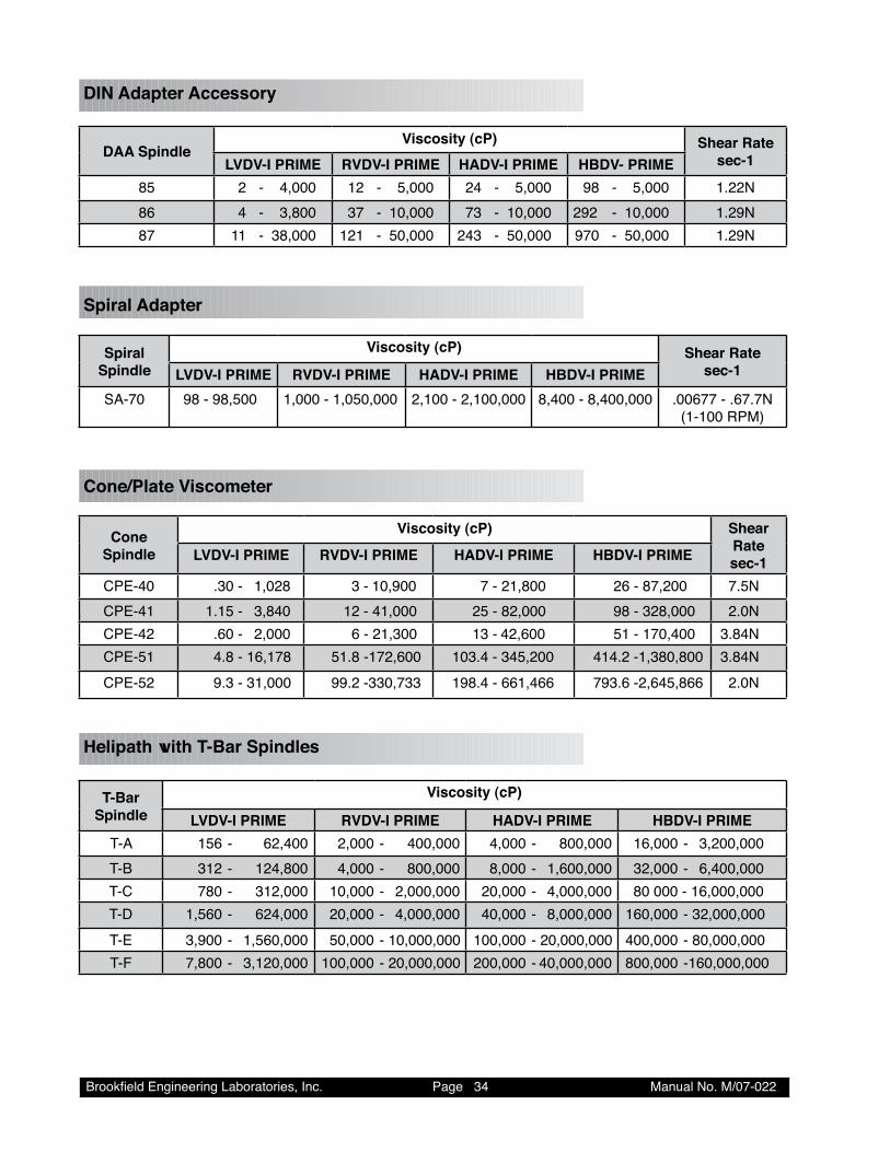
DIN Adapter Accessory
DAA SpindleViscosity (cP) Shear Rate
sec-1LVDV-I PRIME RVDV-I PRIME HADV-I PRIME HBDV- PRIME�� 2 - �,000 �2 - �,000 2� - �,000 �� - �,000 �.22N�� � - �,�00 �7 - �0,000 7� - �0,000 2�2 - �0,000 �.2�N�7 �� - ��,000 �2� - �0,000 2�� - �0,000 �70 - �0,000 �.2�N
Spiral Adapter
Spiral Spindle
Viscosity (cP) Shear Rate sec-1LVDV-I PRIME RVDV-I PRIME HADV-I PRIME HBDV-I PRIME
SA-70 �� - ��,�00 �,000 - �,0�0,000 2,�00 - 2,�00,000 �,�00 - �,�00,000 .00�77 - .�7.7N (�-�00 RPM)
Cone/Plate Viscometer
Cone Spindle
Viscosity (cP) Shear Rate sec-1LVDV-I PRIME RVDV-I PRIME HADV-I PRIME HBDV-I PRIME
CPE-�0 .�0 - �,02� � - �0,�00 7 - 2�,�00 2� - �7,200 7.�NCPE-�� �.�� - �,��0 �2 - ��,000 2� - �2,000 �� - �2�,000 2.0NCPE-�2 .�0 - 2,000 � - 2�,�00 �� - �2,�00 �� - �70,�00 �.��NCPE-�� �.� - ��,�7� ��.� - �72,�00 �0�.� - ���,200 ���.2 - �,��0,�00 �.��NCPE-�2 �.� - ��,000 ��.2 - ��0,7�� ���.� - ���,��� 7��.� - 2,���,��� 2.0N
Helipath with T-Bar Spindles
T-Bar Spindle
Viscosity (cP)
LVDV-I PRIME RVDV-I PRIME HADV-I PRIME HBDV-I PRIMET-A ��� - �2,�00 2,000 - �00,000 �,000 - �00,000 ��,000 - �,200,000T-B ��2 - �2�,�00 �,000 - �00,000 �,000 - �,�00,000 �2,000 - �,�00,000T-C 7�0 - ��2,000 �0,000 - 2,000,000 20,000 - �,000,000 �0 000 - ��,000,000T-D �,��0 - �2�,000 20,000 - �,000,000 �0,000 - �,000,000 ��0,000 - �2,000,000T-E �,�00 - �,��0,000 �0,000 - �0,000,000 �00,000 - 20,000,000 �00,000 - �0,000,000T-F 7,�00 - �,�20,000 �00,000 - 20,000,000 200,000 - �0,000,000 �00,000 - ��0,000,000
Brookfield Engineering Laboratories, Inc. Page �� Manual No. M/07-022
When taking viscosity measurements with the DV-I PRIME Viscometer there are two consider-ations which pertain to the low viscosity limit of effective measurement.
1) Viscosity measurements should be taken within the equivalent % Torque Range from 10% to 100% for any combination of spindle/speed rotation.
2) Viscosity measurements should be taken under laminar flow conditions, not under turbulent flow conditions.
The first consideration has to do with the accuracy of the instrument. All DV-I PRIME Viscometers have a full scale range allowable error of (+/-) 1% of any spindle/speed in use. We discourage taking readings below 10% of range because the potential viscosity error of (+/-) 1% is a relatively high number compared to the instrument reading.
The second consideration involves the mechanics of fluid flow. All rheological measurements of fluid flow properties should be made under laminar flow conditions. Laminar flow is flow wherein all particle movement is in layers directed by the shearing force. For rotational systems, this means all fluid movement must be circumferential. When the inertial forces on the fluid become too great, the fluid can break into turbulent flow wherein the movement of fluid particles becomes random and the flow can not be analyzed with standard math models. This turbulence creates a falsely high viscometer reading with the degree of non-linear increase in reading being directly related to the degree of turbulence in the fluid.
For the following geometries, we have found that an approximate transition point to turbulent flow occurs:
1) No. 1 LV Spindle: 15 cP at 60 RPM 2) No. 1 RV Spindle: 100 cP at 50 RPM (optional spindle available from Brookfield) 3) UL Adapter: 0.85 cP at 60 RPM
Turbulent conditions will exist in these situations whenever the RPM/cP ratio exceeds the values listed above.
Brookfield Engineering Laboratories, Inc. Page �� Manual No. M/07-022
Appendix C - Variables in Viscosity Measurement
As with any instrument measurement, there are variables that can affect a viscometer measurement. These variables may be related to the instrument (viscometer), or the test fluid. Variables related to the test fluid deal with the rheological properties of the fluid, while instrument variables would include the viscometer design and the spindle geometry system utilized.
Rheological Properties
Fluids have different rheological characteristics that can be described by viscometer measurements. We can then work with these fluids to suit the lab or process conditions.
There are two categories of fluids:
Newtonian - These fluids have the same viscosity at different Shear Rates (different RPM’s) and are called Newtonian over the Shear Rate range they are measured.
Non-Newtonian - These fluids have different viscosities at different shear rates (different RPM’s). They fall into two groups:
1) Time Independent 2) Time Dependent
Time Independent means that the viscosity behavior does not change as a function of time when measuring at a specific shear rate.
Pseudoplastic - A pseudoplastic material displays a decrease in viscosity with an in-crease in shear rate, and is also known as “shear thinning”. If you take viscometer readings from a low to a high RPM and then back to the low RPM, and the readings fall upon themselves, the material is time inde-pendent ,pseudoplastic and shear thinning.
Time Dependent means that the viscosity behavior changes as a function of time when measur-ing at a specific shear rate.
Thixotropic - A thixotropic material has decreasing viscosity under constant shear rate. If you set a viscometer at a constant speed recording viscosity val-ues over time and find that the viscosity values decrease with time, the material is thixotropic.
Brookfield publication, “More Solutions to Sticky Problems”, includes a more detailed discussion of rheological properties and non-Newtonian behavior.
Brookfield Engineering Laboratories, Inc. Page �7 Manual No. M/07-022
Viscometer Related Variables
Most fluid viscosities are found to be non-Newtonian. They are dependent on Shear Rate and the spindle geometry conditions. The specifications of the viscometer spindle and chamber geometry will affect the viscosity readings. If one reading is taken at 2.5 rpm, and a second at 50 rpm, the two viscosity values produced will be different because the readings were made at different shear rates. The faster the spindle speed, the higher the shear rate.
The shear rate of a given measurement is determined by: the rotational speed of the spindle, the size and shape of the spindle, the size and shape of the container used and therefore, the distance between the container wall and the spindle surface.
A repeatable viscosity test should control or specify the following:
1) Test temperature 2) Sample container size (or spindle/chamber geometry) 3) Sample volume 4) Viscometer model 5) Spindle used (if using LVDV-I PRIME (#1-4) or RVDV-I PRIME (#1-7) attach the guard
leg) 6) Test speed or speeds (or the shear rate) 7) Length of time or number of spindle revolutions to record viscosity.
Brookfield Engineering Laboratories, Inc. Page �� Manual No. M/07-022
Appendix D - Spindle and Model Codes
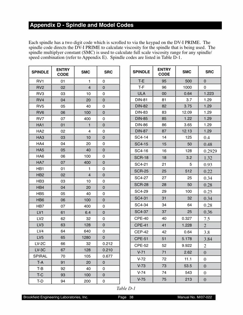
Each spindle has a two digit code which is scrolled to via the keypad on the DV-I PRIME. The spindle code directs the DV-I PRIME to calculate viscosity for the spindle that is being used. The spindle multiplyer constant (SMC) is used to calculate full scale viscosity range for any spindle/speed combination (refer to Appendix E). Spindle codes are listed in Table D-1.
SPINDLE ENTRY CODE SMC SRC
RV� 0� � 0RV2 02 � 0RV� 0� �0 0RV� 0� 20 0RV� 0� �0 0RV� 0� �00 0RV7 07 �00 0HA� 0� � 0HA2 02 � 0HA� 0� �0 0HA� 0� 20 0HA� 0� �0 0HA� 0� �00 0HA7 07 �00 0HB� 0� � 0HB2 02 � 0HB� 0� �0 0HB� 0� 20 0HB� 0� �0 0HB� 0� �00 0HB7 07 �00 0LV� �� �.� 0LV2 �2 �2 0LV� �� �2� 0LV� �� ��0 0LV� �� �2�0 0
LV-2C �� �2 0.2�2LV-�C �7 �2� 0.2�0
SPIRAL 70 �0� 0.�77T-A �� 20 0T-B �2 �0 0T-C �� �00 0T-D �� 200 0
SPINDLE ENTRY CODE SMC SRC
T-E �� �00 0T-F �� �000 0ULA 00 0.�� �.22�
DIN-�� �� �.7 �.2�DIN-�2 �2 �.7� �.2�DIN-�� �� �2.0� �.2�DIN-�� �� �.22 �.2�DIN-�� �� �.�� �.2�DIN-�7 �7 �2.�� �.2�SC�-�� �� �2� 0.4SC�-�� �� �0 0.48SC�-�� �� �2� 0.2929SCR-�� �� �.2 1.32SC�-2� 2� � 0.93SCR-2� 2� ��2 0.22SC�-27 27 2� 0.34SCR-2� 2� �0 0.28SC�-2� 2� �00 0.25SC�-�� �� �2 0.34SC�-�� �� �� 0.28SC�-�7 �7 2� 0.36CPE-�0 �0 0.�27 7.5CPE-�� �� �.22� 2CEP-�2 �2 0.�� 3.8CPE-�� �� �.�7� 3.84CPE-�2 �2 �.�22 2
V-7� 7� 2.�2 0V-72 72 ��.� 0V-7� 7� ��.� 0V-7� 7� ��� 0V-7� 7� 2�� 0
Table D-1
Brookfield Engineering Laboratories, Inc. Page �� Manual No. M/07-022
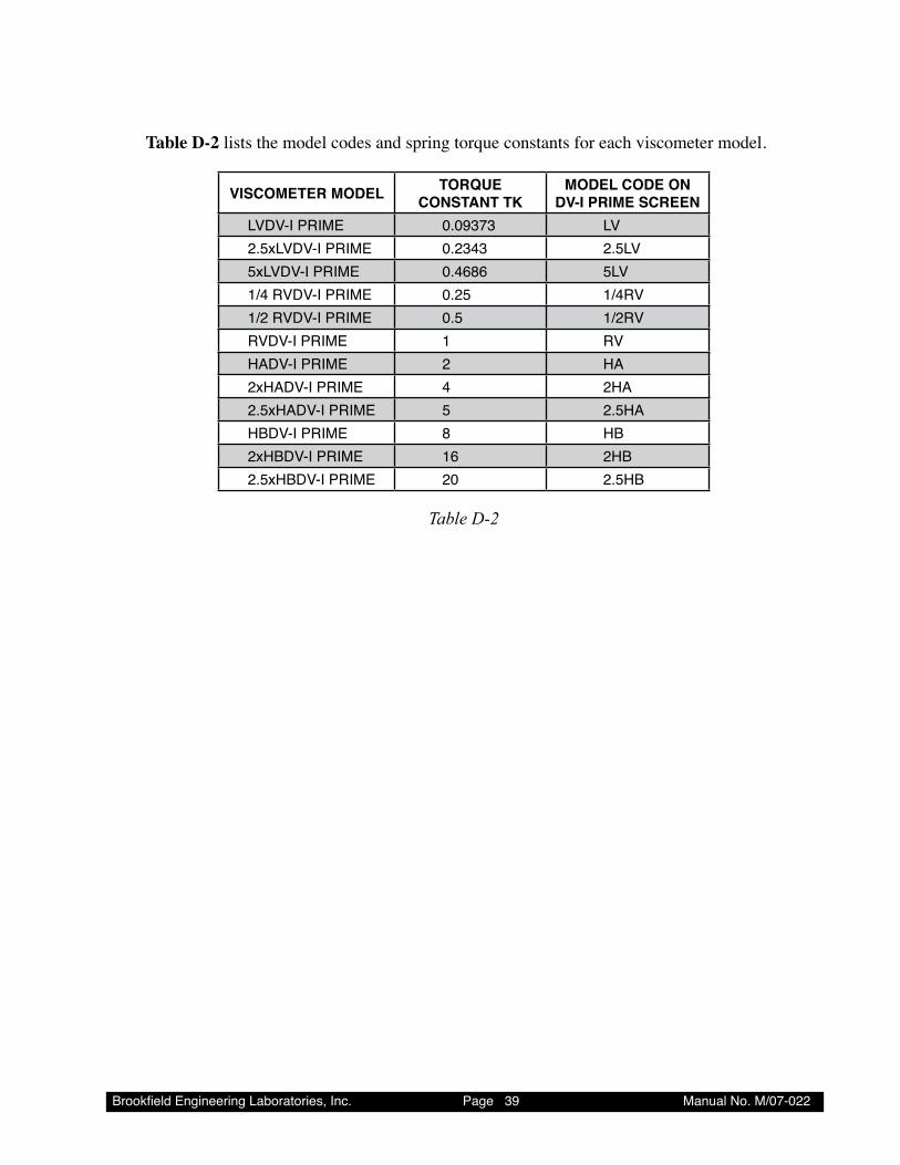
Table D-2 lists the model codes and spring torque constants for each viscometer model.
VISCOMETER MODEL TORQUE CONSTANT TK
MODEL CODE ON DV-I PRIME SCREEN
LVDV-I PRIME 0.0��7� LV2.�xLVDV-I PRIME 0.2��� 2.�LV�xLVDV-I PRIME 0.���� �LV�/� RVDV-I PRIME 0.2� �/�RV�/2 RVDV-I PRIME 0.� �/2RVRVDV-I PRIME � RVHADV-I PRIME 2 HA2xHADV-I PRIME � 2HA2.�xHADV-I PRIME � 2.�HAHBDV-I PRIME � HB2xHBDV-I PRIME �� 2HB2.�xHBDV-I PRIME 20 2.�HB
Table D-2
Brookfield Engineering Laboratories, Inc. Page �0 Manual No. M/07-022
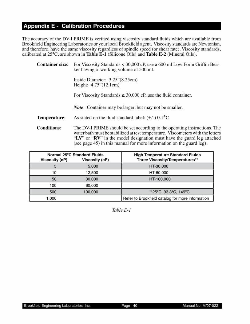
Appendix E - Calibration Procedures
The accuracy of the DV-I PRIME is verified using viscosity standard fluids which are available from Brookfield Engineering Laboratories or your local Brookfield agent. Viscosity standards are Newtonian, and therefore, have the same viscosity regardless of spindle speed (or shear rate). Viscosity standards, calibrated at 25°C, are shown in Table E-1 (Silicone Oils) and Table E-2 (Mineral Oils).
Container size: For Viscosity Standards < 30,000 cP, use a 600 ml Low Form Griffin Bea-ker having a working volume of 500 ml.
Inside Diameter: 3.25”(8.25cm)Height: 4.75”(12.1cm)
For Viscosity Standards ≥ 30,000 cP, use the fluid container. Note: Container may be larger, but may not be smaller.
Temperature: As stated on the fluid standard label: (+/-) 0.1°C
Conditions: The DV-I PRIME should be set according to the operating instructions. The water bath must be stabilized at test temperature. Viscometers with the letters “LV” or “RV” in the model designation must have the guard leg attached (see page 45) in this manual for more information on the guard leg).
Normal 25ºC Standard Fluids Viscosity (cP) Viscosity (cP)
High Temperature Standard Fluids Three Viscosity/Temperatures**
� �,000 HT-�0,000 �0 �2,�00 HT-�0,000 �0 �0,000 HT-�00,000 �00 �0,000 �00 �00,000 **2�ºC, ��.�ºC, ���ºC �,000 Refer to Brookfield catalog for more information
Table E-1
Brookfield Engineering Laboratories, Inc. Page �� Manual No. M/07-022
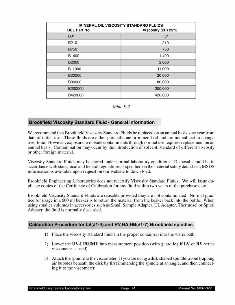
MINERAL OIL VISCOSITY STANDARD FLUIDS BEL Part No. Viscosity (cP) 25ºC
B�� ��B2�0 2�0B7�0 7�0B��00 �,�00B2000 2,000B��000 ��,000B20000 20,000B�0000 �0,000B200000 200,000B�20000 �20,000
Table E-2
BrookfieldViscosityStandardFluid-GeneralInformation
We recommend that Brookfield Viscosity Standard Fluids be replaced on an annual basis, one year from date of initial use. These fluids are either pure silicone or mineral oil and are not subject to change over time. However, exposure to outside contaminants through normal use requires replacement on an annual basis. Contamination may occur by the introduction of solvent, standard of different viscosity or other foreign material.
Viscosity Standard Fluids may be stored under normal laboratory conditions. Disposal should be in accordance with state, local and federal regulations as specified on the material safety data sheet; MSDS information is available upon request on our website to down load.
Brookfield Engineering Laboratories does not recertify Viscosity Standard Fluids. We will issue du-plicate copies of the Certificate of Calibration for any fluid within two years of the purchase date.
Brookfield Viscosity Standard Fluids are reusable provided they are not contaminated. Normal prac-tice for usage in a 600 ml beaker is to return the material from the beaker back into the bottle. When using smaller volumes in accessories such as Small Sample Adapter, UL Adapter, Thermosel or Spiral Adapter, the fluid is normally discarded.
CalibrationProcedureforLV(#1-4)andRV,HA,HB(#1-7)Brookfieldspindles
1) Place the viscosity standard fluid (in the proper container) into the water bath.
2) Lower the DV-I PRIME into measurement position (with guard leg if LV or RV series viscometer is used).
3) Attach the spindle to the viscometer. If you are using a disk shaped spindle, avoid trapping air bubbles beneath the disk by first immersing the spindle at an angle, and then connect-ing it to the viscometer.
Brookfield Engineering Laboratories, Inc. Page �2 Manual No. M/07-022
4) The viscosity standard fluid, together with the spindle and guardleg, should be immersed in the bath for a minimum of 1 hour, stirring the fluid periodically, prior to taking mea-surements.
Don’t introduce air bubbles.
The spindle can be rotated in the fluid to accelerate temperature equilibrium.
5) After 1 hour, check the temperature of the viscosity standard fluid with an accurate ther-mometer. Fluid must be within ± 0.1°C of the specified temperature, normally 25°C. Allow longer soak time if required to come to test temperature.
6) If the fluid is at test temperature, measure the viscosity and record the viscometer reading; include % and cP (m•Pas).
NOTE: The spindle must rotate at least five (5) times before readings are taken.
7) The viscosity reading should equal the cP value on the viscosity fluid standard to within the combined accuracies of the viscometer and the standard (as discussed in the section entitled, Interpretation of Calibration Test Results).
Calibration Procedure for a Small Sample Adapter
When a Small Sample Adapter is used, the water jacket is connected to the water bath and the water is stabilized at the proper temperature:
1) Put the proper amount of viscosity standard fluid into the sample chamber. The amount varies with each spindle/chamber combination. (Refer to the Small Sample Adapter in-struction manual.)
2) Place the sample chamber into the water jacket.
3) Put the spindle into the test fluid and attach the extension link, coupling nut and free hang-ing spindle (or directly attach the solid shaft spindle) to the DV-I PRIME.
4) Allow sufficient time for the viscosity standard, sample chamber and spindle to reach test temperature.
5) Measure the viscosity and record the viscometer reading; include % and cP (m•Pas).
NOTE: The spindle must rotate at least five (5) times before a viscosity reading is taken.
Calibration Procedure for a Thermosel System
A two-step process is recommended for the Thermosel.
1) Evaluate the calibration of the Viscometer alone according to the procedure outlined in this section, entitled Calibration Procedure for LV (#1-4) and RV,HA,HB (#1-7) Brookfield spindles.

Brookfield Engineering Laboratories, Inc. Page �� Manual No. M/07-022
2) Evaluate the Viscometer with the Thermosel according to the procedure decribed be-low.
When a Thermosel System is used, the controller stabilizes the Thermo Container at the test tem-perature. DO NOT USE THE THERMOSEL TO CONTROL TO TEMPERATURES WITHIN 15° OF AMBIENT TEMPERATURES. Consult your Thermosel manual for details.
1) Put the proper amount of HT viscosity standard fluid into the HT-2 sample chamber. The amount varies with the spindle used. (Refer to the Thermosel instruction manual).
2) Place the sample chamber into the Thermo Container.
3) Put the spindle into the test fluid and attach the extension link, coupling nut and free hang-ing spindle (or directly attach the solid shaft spindle) to the DV-I PRIME.
4) Allow sufficient time for the viscosity standard, sample chamber and spindle to reach test temperature.
5) Measure the viscosity and record the viscometer reading; include % and cp (m•Pas).
NOTE: The spindle must rotate at least five (5) times before a viscosity reading is taken.
Calibration Procedure for UL Adapter
When a UL Adapter is used, the water bath is stabilized at the proper temperature:
1) Put the proper amount of viscosity standard fluid into the UL closed Tube. (Refer to the UL Adapter instruction manual).
2) Attach the spindle (with coupling nut) onto the DV-I PRIME.
3) Attach the tube to the mounting bracket.
4) Lower the tube into the water bath reservoir, or if using the ULA-40Y water jacket, con-nect the inlet/outlets to the bath external circulating pump.
5) Allow sufficient time for the viscosity standard, sample chamber and spindle to reach test temperature.
6) Measure the viscosity and record the viscometer reading; include % and cP (m•Pas).
NOTE: The spindle must rotate at least five (5) times before a viscosity reading is taken.
Calibration Procedure for DIN Adapter
When a DIN UL Adapter is used, the water bath is stabilized at the proper temperature:
1) Put the proper amount of viscosity standard fluid into the UL Tube. (Refer to the UL Adapter instruction manual).
2) Attach the spindle (with extension link and coupling nut) onto the DV-I PRIME.
Brookfield Engineering Laboratories, Inc. Page �� Manual No. M/07-022
3) Attach the tube to the mounting channel.
4) Lower the tube into the water bath reservoir, or if using the ULA-40Y water jacket, con-nect the inlet/outlets to the bath external circulating pump.
5) Allow sufficient time for the viscosity standard, sample chamber and spindle to reach test temperature.
6) Measure the viscosity and record the viscometer reading; include % and cP (m•Pas).
NOTE: The spindle must rotate at least five (5) times before a viscosity reading is taken.
Calibration Procedure for a Helipath Stand and T-Bar Spindles
T-Bar spindles should not be used for verifying calibration of the DV-I PRIME Viscometer.
When a Helipath Stand and T-Bar spindles are used: Remove the T-bar spindle and select a standard LV(#1-4) or RV,HA,HB(#1-7) spindle.
Follow the procedures for LV(#1-4) and RV,HA,HB (#1-7) Brookfield spindles outlined above.
Calibration Procedure for Spiral Adapter
1) Place the viscosity standard fluid (in the proper container) into the water bath.
2) Attach the spindle to the viscometer. Attach chamber (SA-1Y) and clamp to the viscom-eter.
3) Lower the DV-I PRIME into measurement position. Operate the viscometer at 50 or 60 RPM until the chamber is fully flooded.
4) The viscosity standard fluid, together with the spindle, should be immersed in the bath. Don’t introduce air bubbles.
Stirring the fluid periodically (operate at 50 or 60 RPM), prior to taking measurements to encourage temperature equilibrium.
NOTE: The spindle must rotate at least five (5) times or for one minute, whichever is greater before readings are taken.
5) Measure viscosity and record the viscometer reading; include % and cP (m•Pas). Instru-ment accuracy is ± 2% of the maximum viscosity range and not the standard 1%.
Calibration Procedure for Cone/Plate Viscometers
1) Follow the procedures outlined in Appendix A for mechanically adjusting the setting of the cone to the plate.
Brookfield Engineering Laboratories, Inc. Page �� Manual No. M/07-022
2) Refer to Appendix A, Table A1, and determine the correct sample volume required for the spindle to be utilized.
3) Select a viscosity standard fluid that will give viscosity readings between 10% and 100% of full scale range. Refer to Appendix B for viscosity ranges of cone spindles. Do not use a silicone viscosity standard fluid with a viscosity value greater than 5000 cP with a Cone/Plate Viscometer. Brookfield offers a complete range of mineral oil viscosity standards suitable for use with Cone/Plate Viscometers. See Table E-2. It is best to use a viscosity standard fluid that will be close to the maximum viscosity for a given cone spindle/speed combination.
Example: LVDV-I PRIME Viscometer, Cone CP-42, Fluid 10 Having a viscosity of 9.7 cP at 25°C
At 60 RPM, the full scale viscosity range is 10.0 cP. Thus, the Viscometer reading should be 97% torque and 9.7 cP viscosity ± 0.197 (closer to ±0.2) cP. The accuracy is a com-bination of Viscometer and fluid tolerance (refer to Interpretation of Calibration Test Results).
4) With the viscometer stopped, remove the sample cup and place the viscosity standard fluid into the cup.
5) Connect the sample cup to the Viscometer. Allow sufficient time for temperature to reach equilibrium.
6) Measure the viscosity and record the Viscometer reading in both % torque and centi-poise.
NOTE: The spindle must rotate at least five (5) times before a viscosity reading is taken.
Interpretation of Calibration Test Results:
When verifying the calibration of the DV-I PRIME, the instrument and viscosity standard fluid error must be combined to calculate the total allowable error.
The DV-I PRIME is accurate to (+/-) 1% of any full scale spindle/speed viscosity range.
Brookfield Viscosity Standards Fluids are accurate to (+/-) 1% of their stated value.
Example: Calculate the acceptable range of viscosity using RVDV-I PRIME with RV-3 Spindle at 2 RPM; Brookfield Standard Fluid 12,500 with a viscosity of 12,257 cP at 25°C:
1) Calculate full scale viscosity range using the equation:
Full Scale Viscosity Range [cP] = TK * SMC * 10,000 RPM Where TK = �.0 from Table D2 SMC = �0 from Table D1
Full Scale Viscosity Range 1 * 10 * 10,000 = 50,000 cP 2
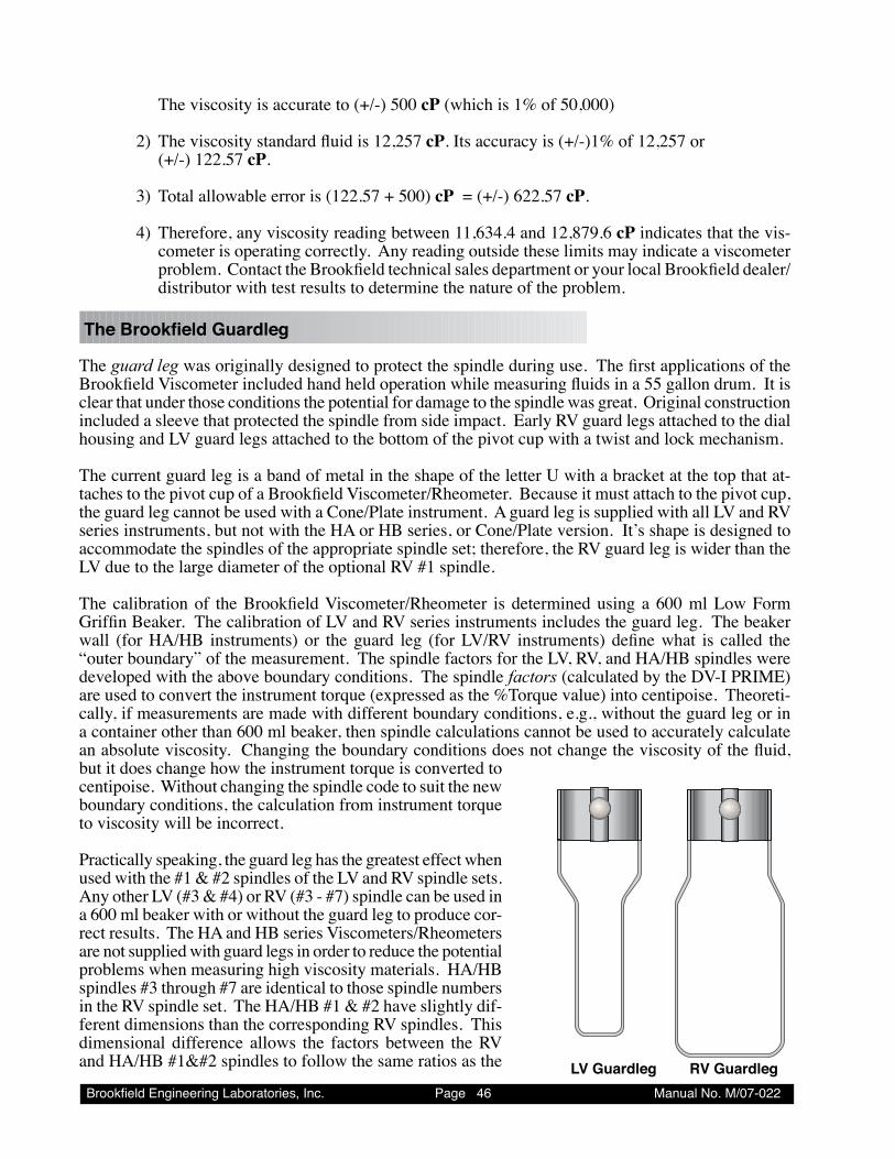
Brookfield Engineering Laboratories, Inc. Page �� Manual No. M/07-022
The viscosity is accurate to (+/-) 500 cP (which is 1% of 50,000)
2) The viscosity standard fluid is 12,257 cP. Its accuracy is (+/-)1% of 12,257 or (+/-) 122.57 cP.
3) Total allowable error is (122.57 + 500) cP = (+/-) 622.57 cP.
4) Therefore, any viscosity reading between 11,634.4 and 12,879.6 cP indicates that the vis-cometer is operating correctly. Any reading outside these limits may indicate a viscometer problem. Contact the Brookfield technical sales department or your local Brookfield dealer/distributor with test results to determine the nature of the problem.
TheBrookfieldGuardleg
The guard leg was originally designed to protect the spindle during use. The first applications of the Brookfield Viscometer included hand held operation while measuring fluids in a 55 gallon drum. It is clear that under those conditions the potential for damage to the spindle was great. Original construction included a sleeve that protected the spindle from side impact. Early RV guard legs attached to the dial housing and LV guard legs attached to the bottom of the pivot cup with a twist and lock mechanism.
The current guard leg is a band of metal in the shape of the letter U with a bracket at the top that at-taches to the pivot cup of a Brookfield Viscometer/Rheometer. Because it must attach to the pivot cup, the guard leg cannot be used with a Cone/Plate instrument. A guard leg is supplied with all LV and RV series instruments, but not with the HA or HB series, or Cone/Plate version. It’s shape is designed to accommodate the spindles of the appropriate spindle set; therefore, the RV guard leg is wider than the LV due to the large diameter of the optional RV #1 spindle.
The calibration of the Brookfield Viscometer/Rheometer is determined using a 600 ml Low Form Griffin Beaker. The calibration of LV and RV series instruments includes the guard leg. The beaker wall (for HA/HB instruments) or the guard leg (for LV/RV instruments) define what is called the “outer boundary” of the measurement. The spindle factors for the LV, RV, and HA/HB spindles were developed with the above boundary conditions. The spindle factors (calculated by the DV-I PRIME) are used to convert the instrument torque (expressed as the %Torque value) into centipoise. Theoreti-cally, if measurements are made with different boundary conditions, e.g., without the guard leg or in a container other than 600 ml beaker, then spindle calculations cannot be used to accurately calculate an absolute viscosity. Changing the boundary conditions does not change the viscosity of the fluid, but it does change how the instrument torque is converted to centipoise. Without changing the spindle code to suit the new boundary conditions, the calculation from instrument torque to viscosity will be incorrect.
Practically speaking, the guard leg has the greatest effect when used with the #1 & #2 spindles of the LV and RV spindle sets. Any other LV (#3 & #4) or RV (#3 - #7) spindle can be used in a 600 ml beaker with or without the guard leg to produce cor-rect results. The HA and HB series Viscometers/Rheometers are not supplied with guard legs in order to reduce the potential problems when measuring high viscosity materials. HA/HB spindles #3 through #7 are identical to those spindle numbers in the RV spindle set. The HA/HB #1 & #2 have slightly dif-ferent dimensions than the corresponding RV spindles. This dimensional difference allows the factors between the RV and HA/HB #1 spindles to follow the same ratios as the LV Guardleg RV Guardleg
Brookfield Engineering Laboratories, Inc. Page �7 Manual No. M/07-022
instrument torque even though the boundary conditions are different.
The recommended procedures of using a 600 ml beaker and the guard leg are difficult for some custom-ers to follow. The guard leg is one more item to clean. In some applications the 500 ml of test fluid required to immerse the spindles in a 600 ml beaker is not available. In practice, a smaller vessel may be used and the guard leg is removed. The Brookfield Viscometer/Rheometer will produce an accurate and repeatable torque reading under any measurement circumstance. However, the conversion of this torque reading to centipoise will only be correct if the factor used was developed for those specific conditions. Brookfield has outlined a method for recalibrating a Brookfield Viscometer/Rheometer to any measurement circumstance in “More Solutions to Sticky Problems”, Section 3.4.10. It is impor-tant to note that for many viscometer users the true viscosity is not as important as a repeatable day to day value. This repeatable value can be obtained without any special effort for any measurement circumstance. But, it should be known that this type of torque reading will not convert into a correct centipoise value when using a Brookfield factor if the boundary conditions are not those specified by Brookfield.
The guard leg is a part of the calibration check of the Brookfield LV and RV series Viscometer/Rhe-ometer. Our customers should be aware of its existence, its purpose and the effect that it may have on data. With this knowledge, the viscometer user may make modifications to the recommended method of operation to suit their needs.
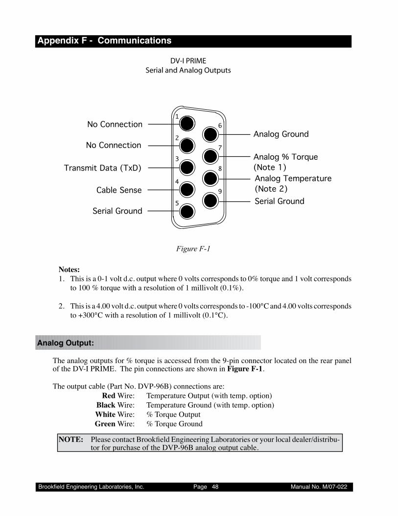
Brookfield Engineering Laboratories, Inc. Page �� Manual No. M/07-022
Appendix F - Communications
2
3
4
5
6
7
8
9
1No Connection
Transmit Data (TxD)
No Connection
Serial Ground
Analog Ground
Analog % Torque(Note 1)Analog Temperature(Note 2)
DV-I PRIMESerial and Analog Outputs
Cable SenseSerial Ground
Figure F-1
Notes:1. This is a 0-1 volt d.c. output where 0 volts corresponds to 0% torque and 1 volt corresponds
to 100 % torque with a resolution of 1 millivolt (0.1%).
2. This is a 4.00 volt d.c. output where 0 volts corresponds to -100°C and 4.00 volts corresponds to +300°C with a resolution of 1 millivolt (0.1°C).
Analog Output:
The analog outputs for % torque is accessed from the 9-pin connector located on the rear panel of the DV-I PRIME. The pin connections are shown in Figure F-1.
The output cable (Part No. DVP-96B) connections are: Red Wire: Temperature Output (with temp. option) Black Wire: Temperature Ground (with temp. option) White Wire: % Torque Output Green Wire: % Torque Ground
NOTE: Please contact Brookfield Engineering Laboratories or your local dealer/distribu-tor for purchase of the DVP-96B analog output cable.
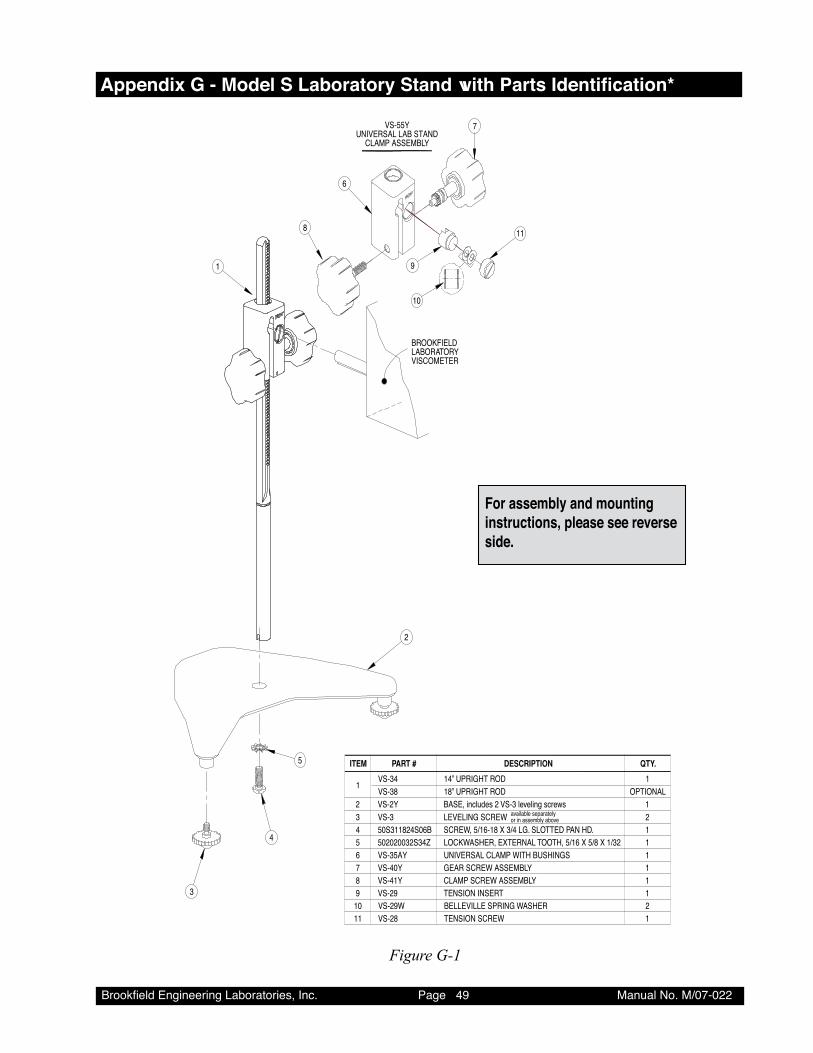
Brookfield Engineering Laboratories, Inc. Page �� Manual No. M/07-022
AppendixG-ModelSLaboratoryStandwithPartsIdentification*
BROOKFIELDLABORATORYVISCOMETER
available separatelyor in assembly above
ITEM PART #
1098765432
1
211111121
OPTIONAL
QTY.
VS-29WVS-29VS-41YVS-40YVS-35AY502020032S34Z50S311824S06BVS-3VS-2Y
VS-34VS-38
1DESCRIPTION
BELLEVILLE SPRING WASHERTENSION INSERTCLAMP SCREW ASSEMBLYGEAR SCREW ASSEMBLYUNIVERSAL CLAMP WITH BUSHINGS LOCKWASHER, EXTERNAL TOOTH, 5/16 X 5/8 X 1/32SCREW, 5/16-18 X 3/4 LG. SLOTTED PAN HD.LEVELING SCREWBASE, includes 2 VS-3 leveling screws
14” UPRIGHT ROD18” UPRIGHT ROD
11 1VS-28 TENSION SCREW
VS-55YUNIVERSAL LAB STAND
CLAMP ASSEMBLY
2
3
4
5
1
8
6
7
9
10
11
MODEL S LABORATORY STANDPARTS IDENTIFICATION & INSTRUCTIONS
For assembly and mounting instructions, please see reverse side.
Figure G-1
Brookfield Engineering Laboratories, Inc. Page �0 Manual No. M/07-022
UNPACKING
Check carefully to see that all the components are received with no concealed damage. 1 Base, VS-2, with 2 Leveling Screws, VS-3, packed in a cardboard carton1 Upright Rod, VS-34, with attached Clamp Assembly, VS-55Y, Mounting Screw and 2 Lockwashers
ASSEMBLY
1. Remove the base assembly from the carton.
2. Remove the screw and washer from the upright rod. Place the rod and clamp assembly into the hole in the top of the base.
NOTE: The “Front” designation on the clamp assembly should face the opening of the legs, i.e., parallel to the leveling feet.
3. Rotate the rod/clamp assembly slightly until the slot on the bottom of the rod intersects the pin located in the base.
4. While holding the rod and base together, insert the slotted screw and washer as shown and tighten securely.
5. Adjust the VS-28 tension screw so that the clamp assembly is not loose on the upright rod.
VISCOMETER MOUNTING
DV-I PRIME Digital Viscometer:Insert the Viscometer mounting rod into the hole (with the cut-away slot) in the clamp assembly. Adjust the instrument level until the bubble is centered from right to left and tighten the clamp knob (clockwise). Use the leveling screws to “fine” adjust the viscometer level.
NOTE: If the Digital Viscometer cannot be leveled, check to insure that the rod is installed with the gear rack facing forward.
CAUTION: Do not tighten the clamp knob unless the viscometer mounting rod is inserted in the clamp assembly.
NOTE: If the clamp is taken off the upright rod, the tension insert (Part No. VS-29) must be properly aligned for the clamp to fit back onto the upright rod.
When the tension insert (Part No. VS-29) is inserted, its slot must be in the verti-
cal position parallel to the upright rod. If the slot is not in the correct position, the clamp will not slide down over the upright rod. Use a small screwdriver or pencil to move it into the correct position
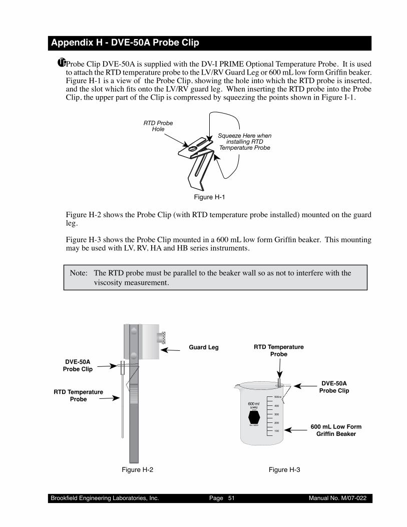
Brookfield Engineering Laboratories, Inc. Page �� Manual No. M/07-022
Appendix H - DVE-50A Probe Clip
TpProbe Clip DVE-50A is supplied with the DV-I PRIME Optional Temperature Probe. It is used to attach the RTD temperature probe to the LV/RV Guard Leg or 600 mL low form Griffin beaker. Figure H-1 is a view of the Probe Clip, showing the hole into which the RTD probe is inserted, and the slot which fits onto the LV/RV guard leg. When inserting the RTD probe into the Probe Clip, the upper part of the Clip is compressed by squeezing the points shown in Figure I-1.
RTD Probe Hole
Squeeze Here wheninstalling RTD
Temperature Probe
Figure H-�
Figure H-2 shows the Probe Clip (with RTD temperature probe installed) mounted on the guard leg.
Figure H-3 shows the Probe Clip mounted in a 600 mL low form Griffin beaker. This mounting may be used with LV, RV, HA and HB series instruments.
Note: The RTD probe must be parallel to the beaker wall so as not to interfere with the viscosity measurement.
Guard Leg
DVE-50AProbe Clip
RTD TemperatureProbe
600 mlUSA
No.14000
500ml
400
300
200
100
RTD TemperatureProbe
DVE-50AProbe Clip
600 mL Low FormGriffin Beaker
Figure H-2 Figure H-�
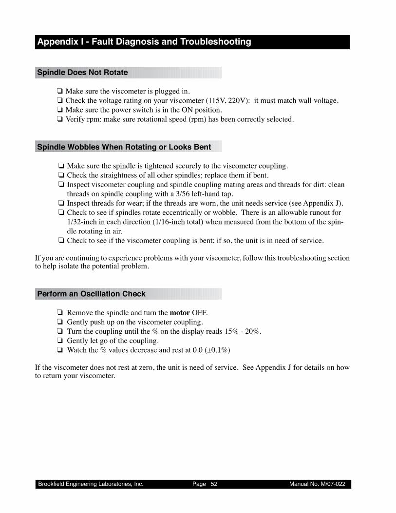
Brookfield Engineering Laboratories, Inc. Page �2 Manual No. M/07-022
Appendix I - Fault Diagnosis and Troubleshooting
Spindle Does Not Rotate
❏ Make sure the viscometer is plugged in. ❏ Check the voltage rating on your viscometer (115V, 220V): it must match wall voltage. ❏ Make sure the power switch is in the ON position. ❏ Verify rpm: make sure rotational speed (rpm) has been correctly selected.
Spindle Wobbles When Rotating or Looks Bent
❏ Make sure the spindle is tightened securely to the viscometer coupling. ❏ Check the straightness of all other spindles; replace them if bent. ❏ Inspect viscometer coupling and spindle coupling mating areas and threads for dirt: clean
threads on spindle coupling with a 3/56 left-hand tap. ❏ Inspect threads for wear; if the threads are worn, the unit needs service (see Appendix J). ❏ Check to see if spindles rotate eccentrically or wobble. There is an allowable runout for
1/32-inch in each direction (1/16-inch total) when measured from the bottom of the spin-dle rotating in air.
❏ Check to see if the viscometer coupling is bent; if so, the unit is in need of service.
If you are continuing to experience problems with your viscometer, follow this troubleshooting section to help isolate the potential problem.
Perform an Oscillation Check
❏ Remove the spindle and turn the motor OFF. ❏ Gently push up on the viscometer coupling. ❏ Turn the coupling until the % on the display reads 15% - 20%. ❏ Gently let go of the coupling. ❏ Watch the % values decrease and rest at 0.0 (±0.1%)
If the viscometer does not rest at zero, the unit is need of service. See Appendix J for details on how to return your viscometer.
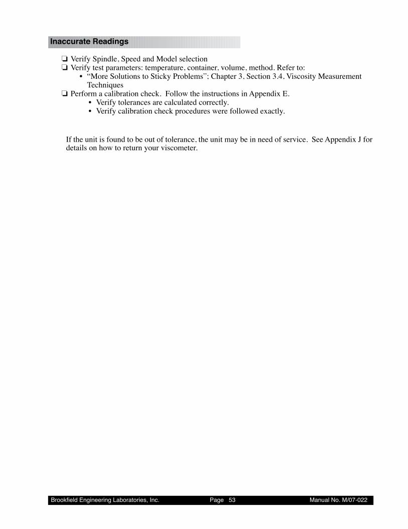
Brookfield Engineering Laboratories, Inc. Page �� Manual No. M/07-022
Inaccurate Readings
❏ Verify Spindle, Speed and Model selection ❏ Verify test parameters: temperature, container, volume, method. Refer to: • “More Solutions to Sticky Problems”; Chapter 3, Section 3.4, Viscosity Measurement
Techniques ❏ Perform a calibration check. Follow the instructions in Appendix E. • Verify tolerances are calculated correctly. • Verify calibration check procedures were followed exactly.
If the unit is found to be out of tolerance, the unit may be in need of service. See Appendix J for details on how to return your viscometer.
Brookfield Engineering Laboratories, Inc. Page �� Manual No. M/07-022
Appendix J - Warranty Repair and Service
Warranty
Brookfield Viscometers are guaranteed for one year from date of purchase against defects in materials and workmanship. They are certified using primary viscosity standards traceable to the National Institute of Standards and Technology (NIST). The Viscometer must be returned to Brookfield Engineering Laboratories, Inc. or the Brookfield dealer from whom it was purchased for no charge warranty ser-vice. Transportation is at the purchaser’s expense. The Viscometer should be shipped in its carrying case together with all spindles and the guardleg if originally provided with the instrument.
For repair or service in the United States return to:
Brookfield Engineering Laboratories, Inc.11 Commerce Boulevard
Middleboro, MA 02346 U.S.A.Telephone: (508) 946-6200 FAX: (508) 923-5009
www.brookfieldengineering.com
For repair or service outside the United States consult Brookfield Engineering Laboratories, Inc. or the dealer from whom you purchased the instrument.
For repair or service in the United Kingdom return to:
Brookfield Viscometers Limited1 Whitehall Estate
Flex Meadow, Pinnacles WestHarlow, Essex CM19 5TJ, United Kingdom
Telephone: (44) 27/945 1774 FAX: (44) 27/945 1775www.brookfield.co.uk
For repair or service in Germany return to:
Brookfield Engineering Laboratories Vertriebs GmbHHauptstrasse 18
D-73547 Lorch, GermanyTelephone: (49) 7172/927100 FAX: (49) 7172/927105
www.brookfield-gmbh.de
For repair or service in China return to:
Guangzhou Brookfield Viscometers and Texture Instruments Service Company Ltd.Room C1, 5/F, Tianxing Building East Tower, No. 21, Zhongshan Yi Road, Yuexiu District
Guangzhou, 510600, P. R. ChinaTelephone: (86) 20/3760-0548 FAX: (86) 20/3760-0548
www.brookfield.com.cn
On-siteserviceatyourfacilityisalsoavailablefromBrookfield.PleasecontactourServiceDepartmentinthe United States, United Kingdom, Germany or China for details.
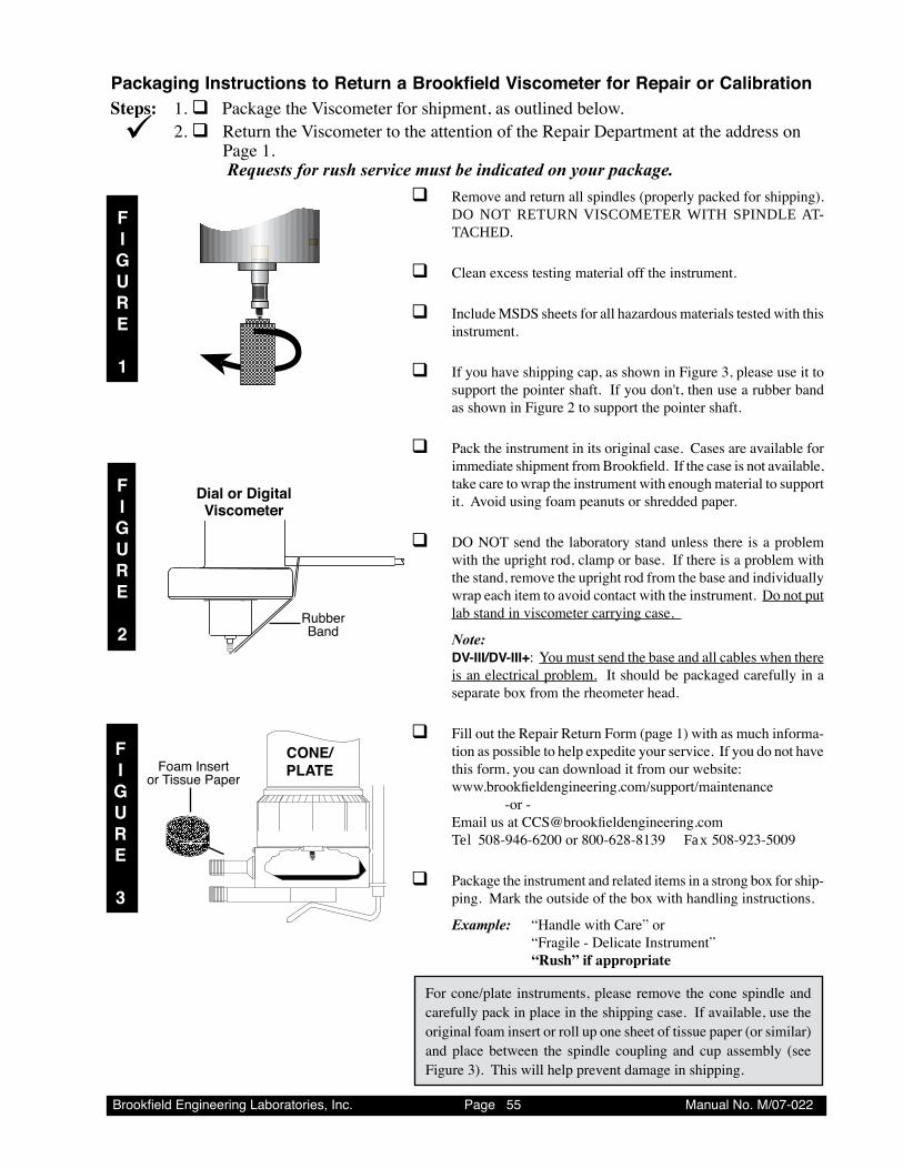
Brookfield Engineering Laboratories, Inc. Page �� Manual No. M/07-022
q Remove and return all spindles (properly packed for shipping). DO NOT RETURN VISCOMETER WITH SPINDLE AT-TACHED.
q Clean excess testing material off the instrument.
q Include MSDS sheets for all hazardous materials tested with this instrument.
q If you have shipping cap, as shown in Figure 3, please use it to support the pointer shaft. If you don't, then use a rubber band as shown in Figure 2 to support the pointer shaft.
q Pack the instrument in its original case. Cases are available for immediate shipment from Brookfield. If the case is not available, take care to wrap the instrument with enough material to support it. Avoid using foam peanuts or shredded paper.
q DO NOT send the laboratory stand unless there is a problem with the upright rod, clamp or base. If there is a problem with the stand, remove the upright rod from the base and individually wrap each item to avoid contact with the instrument. Do not put lab stand in viscometer carrying case.
Note: DV-III/DV-III+: You must send the base and all cables when there
is an electrical problem. It should be packaged carefully in a separate box from the rheometer head.
q Fill out the Repair Return Form (page 1) with as much informa-tion as possible to help expedite your service. If you do not have this form, you can download it from our website:
www.brookfieldengineering.com/support/maintenance -or - Email us at [email protected] Tel 508-946-6200 or 800-628-8139 Fax 508-923-5009
q Package the instrument and related items in a strong box for ship-ping. Mark the outside of the box with handling instructions.
Example: “Handle with Care” or “Fragile - Delicate Instrument” “Rush” if appropriate
PackagingInstructionstoReturnaBrookfieldViscometerforRepairorCalibration
FIGURE
3
FIGURE
1
For cone/plate instruments, please remove the cone spindle and carefully pack in place in the shipping case. If available, use the original foam insert or roll up one sheet of tissue paper (or similar) and place between the spindle coupling and cup assembly (see Figure 3). This will help prevent damage in shipping.
Steps: 1. qPackage the Viscometer for shipment, as outlined below. 2. q Return the Viscometer to the attention of the Repair Department at the address on
Page 1. Requests for rush service must be indicated on your package.
¸
CONE/PLATEFoam Insert
or Tissue Paper
FIGURE
2Rubber Band
Dial or DigitalViscometer
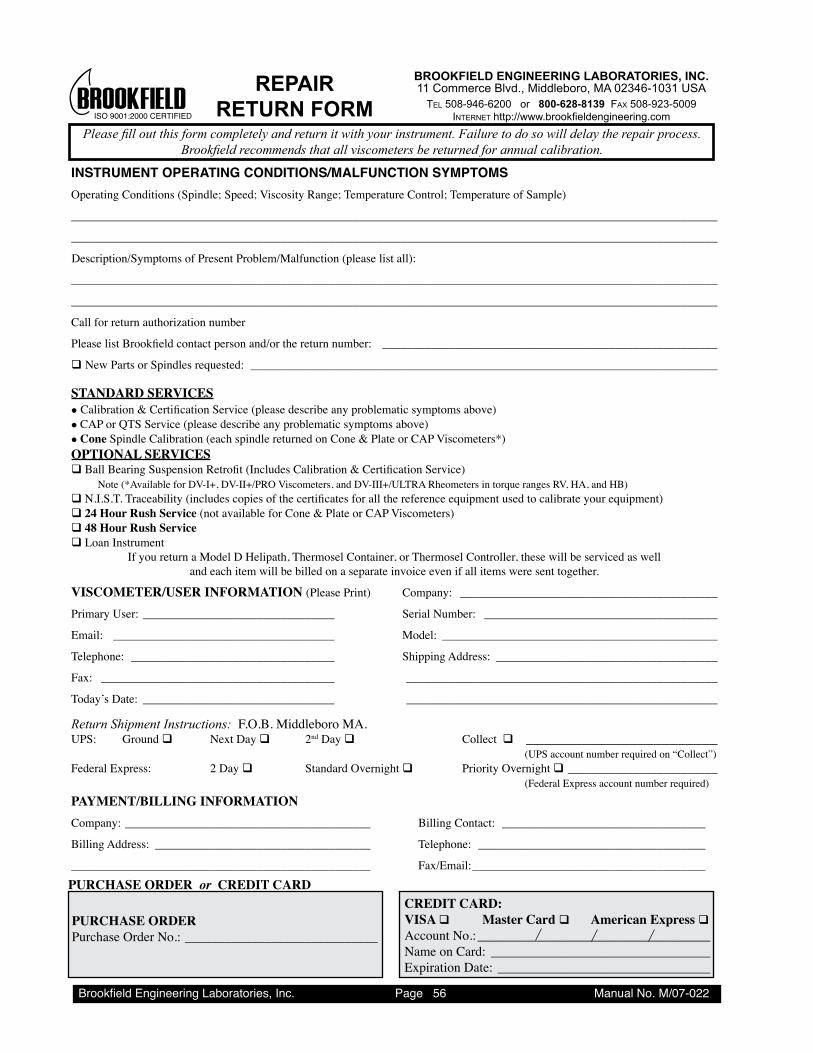
Brookfield Engineering Laboratories, Inc. Page �� Manual No. M/07-022
INSTRUMENT OPERATING CONDITIONS/MALFUNCTION SYMPTOMSOperating Conditions (Spindle; Speed; Viscosity Range; Temperature Control; Temperature of Sample)
____________________________________________________________________________________________________________
____________________________________________________________________________________________________________
Description/Symptoms of Present Problem/Malfunction (please list all):
____________________________________________________________________________________________________________
____________________________________________________________________________________________________________
Call for return authorization number
Please list Brookfield contact person and/or the return number: ________________________________________________________
q New Parts or Spindles requested: ______________________________________________________________________________
STANDARD SERVICESl Calibration & Certification Service (please describe any problematic symptoms above)l CAP or QTS Service (please describe any problematic symptoms above)l Cone Spindle Calibration (each spindle returned on Cone & Plate or CAP Viscometers*)OPTIONAL SERVICESq Ball Bearing Suspension Retrofit (Includes Calibration & Certification Service) Note (*Available for DV-I+, DV-II+/PRO Viscometers, and DV-III+/ULTRA Rheometers in torque ranges RV, HA, and HB) q N.I.S.T. Traceability (includes copies of the certificates for all the reference equipment used to calibrate your equipment)q 24 Hour Rush Service (not available for Cone & Plate or CAP Viscometers)q 48 Hour Rush Service q Loan Instrument
If you return a Model D Helipath, Thermosel Container, or Thermosel Controller, these will be serviced as welland each item will be billed on a separate invoice even if all items were sent together.
VISCOMETER/USER INFORMATION (Please Print) Company: ___________________________________________
Primary User: ________________________________ Serial Number: _______________________________________
Email: _____________________________________ Model: ______________________________________________
Telephone: __________________________________ Shipping Address: _____________________________________
Fax: _______________________________________ ____________________________________________________
Today’s Date: ________________________________ ____________________________________________________
Return Shipment Instructions: F.O.B. Middleboro MA. UPS: Ground q Next Day q 2nd Day q Collect q ________________________ (UPS account number required on “Collect”)Federal Express: 2 Day q Standard Overnight q Priority Overnight q _________________________ (Federal Express account number required)
PAYMENT/BILLING INFORMATIONCompany: _________________________________________ Billing Contact: __________________________________
Billing Address: ____________________________________ Telephone: ______________________________________
__________________________________________________ Fax/Email: _______________________________________
PURCHASE ORDERPurchase Order No.: _____________________________
CREDIT CARD:VISA q Master Card q American Express qAccount No.: ___________________________________Name on Card: _________________________________Expiration Date: ________________________________
ISO �00�:2000 CERTIFIEDBROOKFIELD REPAIR
RETURN FORM
BROOKFIELD ENGINEERING LABORATORIES, INC.11 Commerce Blvd., Middleboro, MA 02346-1031 USA
Tel 508-946-6200 or 800-628-8139 Fax 508-923-5009InTerneT http://www.brookfieldengineering.com
PURCHASE ORDER or CREDIT CARD
Pleasefilloutthisformcompletelyandreturnitwithyourinstrument.Failuretodosowilldelaytherepairprocess. Brookfieldrecommendsthatallviscometersbereturnedforannualcalibration.
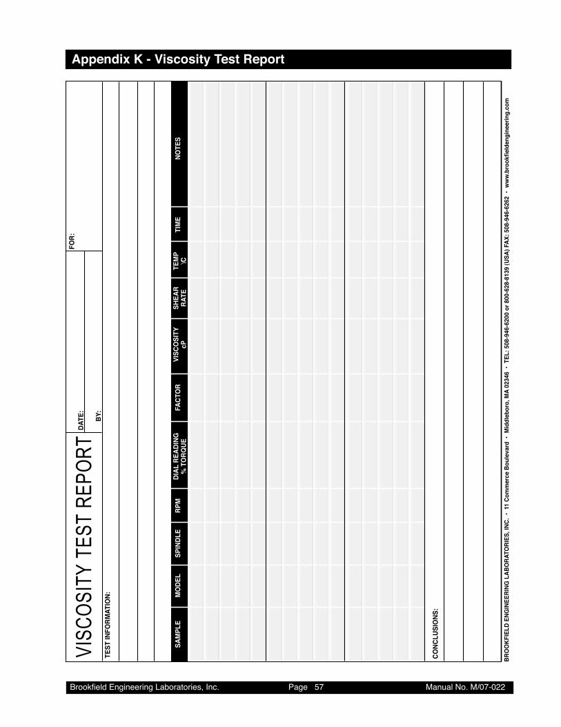
Brookfield Engineering Laboratories, Inc. Page �7 Manual No. M/07-022
Appendix K - Viscosity Test Report
VISC
OSI
TY T
EST
REP
OR
T
SAM
PLE
MO
DEL
SPIN
DLE
RPM
DIAL
REA
DING
FACT
OR
VISC
OSI
TYSH
EAR
TEM
PTI
ME
NOTE
S%
TO
RQUE
cPRA
TEϒC
TEST
INFO
RMAT
ION:
CONC
LUSI
ONS
:
FOR:
DATE
:
BY:
BRO
OKF
IELD
ENG
INEE
RING
LAB
ORA
TORI
ES, I
NC.
• 11
Com
mer
ce B
oule
vard
• M
iddl
ebor
o, M
A 02
346
• T
EL: 5
08-9
46-6
200
or 8
00-6
28-8
139
(USA
) FAX
: 508
-946
-626
2 •
ww
w.b
rook
field
engi
neer
ing.
com