Embed Size (px)
Citation preview
®
53-1002554-01
*53-1002554-01*
53-1002554-0122 August 2012
Brocade VDX 8770-4QuickStart Guide
Copyright © 2012, Brocade Communications Systems, Incorporated.
Brocade, Brocade Assurance, the B-wing symbol, BigIron, DCX, Fabric OS, FastIron, MLX, NetIron, SAN Health, ServerIron, TurboIron, VCS, and VDX are registered trademarks, and AnyIO, Brocade One, CloudPlex, Effortless Networking, ICX, NET Health, OpenScript, and The Effortless Network are trademarks of Brocade Communications Systems, Inc., in the United States and/or in other countries. Other brands, products, or service names mentioned may be trademarks of their respective owners.
Notice: This document is for informational purposes only and does not set forth any warranty, expressed or implied, concerning any equipment, equipment feature, or service offered or to be offered by Brocade. Brocade reserves the right to make changes to this document at any time, without notice, and assumes no responsibility for its use. This informational document describes features that may not be currently available. Contact a Brocade sales office for information on feature and product availability. Export of technical data contained in this document may require an export license from the United States government.
The authors and Brocade Communications Systems, Inc. shall have no liability or responsibility to any person or entity with respect to any loss, cost, liability, or damages arising from the information contained in this book or the computer programs that accompany it.
The product described by this document may contain “open source” software covered by the GNU General Public License or other open source license agreements. To find out which open source software is included in Brocade products, view the licensing terms applicable to the open source software, and obtain a copy of the programming source code, please visit http://www.brocade.com/support/oscd.
Brocade Communications Systems, Incorporated
Document History
Corporate and Latin American HeadquartersBrocade Communications Systems, Inc.130 Holger WaySan Jose, CA 95134 Tel: 1-408-333-8000 Fax: 1-408-333-8101 E-mail: [email protected]
Asia-Pacific HeadquartersBrocade Communications Systems China HK, Ltd.No. 1 Guanghua RoadChao Yang DistrictUnits 2718 and 2818Beijing 100020, ChinaTel: +8610 6588 8888Fax: +8610 6588 9999E-mail: [email protected]
European HeadquartersBrocade Communications Switzerland SàrlCentre SwissairTour B - 4ème étage29, Route de l'AéroportCase Postale 105CH-1215 Genève 15Switzerland Tel: +41 22 799 5640Fax: +41 22 799 5641E-mail: [email protected]
Asia-Pacific HeadquartersBrocade Communications Systems Co., Ltd. (Shenzhen WFOE)Citic PlazaNo. 233 Tian He Road NorthUnit 1308 – 13th FloorGuangzhou, ChinaTel: +8620 3891 2000Fax: +8620 3891 2111E-mail: [email protected]
Document Title Publication Number
Summary of Changes
Publication Date
Brocade VDX 8770-4 QuickStart Guide 53-1002554-01 New document. August 2012
2 of 32 Brocade VDX 8770-4 QuickStart GuidePublication Number: 53-1002554-01
In this guide•Introduction. . . . . . . . . . . . . . . . . . . . . . . . . . . . . . . . . . . . . . . . . . . . . . . . . . . . 4
•Safety notices . . . . . . . . . . . . . . . . . . . . . . . . . . . . . . . . . . . . . . . . . . . . . . . . . . 5
•Danger notices . . . . . . . . . . . . . . . . . . . . . . . . . . . . . . . . . . . . . . . . . . . . . . . . . 6
•Caution notices. . . . . . . . . . . . . . . . . . . . . . . . . . . . . . . . . . . . . . . . . . . . . . . . . 6
•ESD precautions. . . . . . . . . . . . . . . . . . . . . . . . . . . . . . . . . . . . . . . . . . . . . . . . 6
•Brocade VDX 8770-4, port side. . . . . . . . . . . . . . . . . . . . . . . . . . . . . . . . . . . . 6
•Brocade VDX 8770-4, nonport side . . . . . . . . . . . . . . . . . . . . . . . . . . . . . . . . 7
•Items included with the Brocade VDX 8770-4 . . . . . . . . . . . . . . . . . . . . . . . . 8
•Preparing for the Brocade VDX 8770-4 installation. . . . . . . . . . . . . . . . . . . . 9
•Unpacking and installing the Brocade VDX 8770-4. . . . . . . . . . . . . . . . . . . 13
•Port numbering. . . . . . . . . . . . . . . . . . . . . . . . . . . . . . . . . . . . . . . . . . . . . . . . 14
•Inserting a management module . . . . . . . . . . . . . . . . . . . . . . . . . . . . . . . . . 14
•Inserting a switch fabric module . . . . . . . . . . . . . . . . . . . . . . . . . . . . . . . . . . 15
•Inserting a line card . . . . . . . . . . . . . . . . . . . . . . . . . . . . . . . . . . . . . . . . . . . . 16
•Inserting power supplies . . . . . . . . . . . . . . . . . . . . . . . . . . . . . . . . . . . . . . . . 17
•Providing power to the Brocade VDX 8770-4 . . . . . . . . . . . . . . . . . . . . . . . . 19
•Preparing to configure the Brocade VDX 8770-4. . . . . . . . . . . . . . . . . . . . . 20
•Establishing a serial connection to the Brocade VDX 8770-4. . . . . . . . . . . 20
•Logging in to the serial console port . . . . . . . . . . . . . . . . . . . . . . . . . . . . . . . 22
•Changing the RBridge ID . . . . . . . . . . . . . . . . . . . . . . . . . . . . . . . . . . . . . . . . 22
•Assigning permanent passwords . . . . . . . . . . . . . . . . . . . . . . . . . . . . . . . . . 23
•Configuring the IP addresses . . . . . . . . . . . . . . . . . . . . . . . . . . . . . . . . . . . . 23
•Logging off the serial console port and disconnecting the serial cable . . . 24
•Establishing an Ethernet connection to the Brocade VDX 8770-4 . . . . . . . 24
•Customizing a host name . . . . . . . . . . . . . . . . . . . . . . . . . . . . . . . . . . . . . . . 25
•Customizing a switch name. . . . . . . . . . . . . . . . . . . . . . . . . . . . . . . . . . . . . . 25
•Setting the date and time . . . . . . . . . . . . . . . . . . . . . . . . . . . . . . . . . . . . . . . 26
•Determining installed software licenses. . . . . . . . . . . . . . . . . . . . . . . . . . . . 28
•Saving your changes . . . . . . . . . . . . . . . . . . . . . . . . . . . . . . . . . . . . . . . . . . . 28
•Verifying correct operation. . . . . . . . . . . . . . . . . . . . . . . . . . . . . . . . . . . . . . . 29
•Backing up the configuration . . . . . . . . . . . . . . . . . . . . . . . . . . . . . . . . . . . . 29
•Connecting network devices . . . . . . . . . . . . . . . . . . . . . . . . . . . . . . . . . . . . . 30
•Installing transceivers and attaching cables . . . . . . . . . . . . . . . . . . . . . . . . 30
•Managing cables . . . . . . . . . . . . . . . . . . . . . . . . . . . . . . . . . . . . . . . . . . . . . . 31
•Creating Brocade inter-switch link trunks. . . . . . . . . . . . . . . . . . . . . . . . . . . 32
Brocade VDX 8770-4 QuickStart Guide 3 of 32Publication Number: 53-1002554-01
IntroductionYou can set up and install the Brocade VDX 8770-4 in the following ways:
• As a standalone unit on a flat surface
• In a four-post rack with the Intake Duct Kit
• In a four-post rack
• In a two-post telecommunications (Telco) rack
This manual describes how to set up the Brocade VDX 8770-4 as a standalone unit. For rack mount installation instructions, refer to the manual that comes with the separately ordered rack kit.
Table 1 describes the main installation and setup tasks, the estimated time required for each, and the items required to complete the task based on a fully populated Brocade VDX 8770-4 (192 10 GbE ports). Configurations with fewer ports require less time. These time estimates assume a prepared installation site and appropriate power and network connectivity.
DANGER
The procedures in this manual are for qualified service personnel.
TABLE 1 Installation tasks, time, and items required
Installation task Time estimate Items required
Site preparation and unpacking Brocade VDX 8770-4
30 minutes #2 Phillips screwdriver.Pallet jack.Hydraulic lift or assisted lift, able to raise to a minimum of 140 cm (55 in.), with a minimum capacity of 113 kg (250 lb). A fully loaded version of the Brocade VDX 8770-4 weighs 86.18 kg (190 lbs).
Installing the rack mount kit or intake duct rack mount kit
30 minutes
Refer to the proper rack mount kit instructions for your specific rack..Mounting and securing Brocade VDX
8770-4 in the rack30 minutes
Inserting modules and power supplies 5-10 minutes per unit
Management modules, switch fabric modules, line cards, power supplies (AC or DC).
Installing power cables and powering on the Brocade VDX 8770-4
20 minutes Power cables (provided in the Brocade VDX 8770-4 accessory kit).
Establishing a serial connection, logging on to the Brocade VDX 8770-4, and configuring the IP addresses
20 minutes Serial cable (also called the console cable - provided in the accessory kit).Workstation computer with a serial (console) port or terminal server port and a terminal emulator application (such as HyperTerminal).Ethernet IP addresses for the Brocade VDX 8770-4 switch and for management modules: total two or three addresses, depending on the number of management modules installed.
4 of 32 Brocade VDX 8770-4 QuickStart GuidePublication Number: 53-1002554-01
CAUTION
The Brocade VDX 8770-4 with DC power sources are intended for installation in restricted access areas only. A restricted access area is a location where access can be gained only by service personnel through the use of a special tool, lock and key, or other means of security, and is controlled by the authority responsible for the location.
CAUTION
The Brocade VDX 8770-4 with AC power sources are intended for installation in restricted access areas only. A restricted access area is a location where access can be gained only by service personnel through the use of a special tool, lock and key, or other means of security.
Safety noticesWhen using this product, observe the danger, caution, and attention notices in this manual. The notices are accompanied by symbols that represent the severity of the safety condition.
NOTETranslated safety notices are in the Brocade Product Safety Notices publication, which is on the CD-ROM that accompanies this product.
The danger and caution notices are listed in numerical order based on their IDs, which are displayed in parentheses, for example (D004), at the end of each notice. Use this ID to locate the translations of these danger and caution notices in the Brocade Product Safety Notices.
Installing an Ethernet cable, opening a Telnet session, and configuring the Brocade VDX 8770-4 date and time and additional system parameters. Verify and back up configuration.
20 minutes Ethernet cabling (optional) for Telnet access.Refer to the Brocade Network OS Administrator’s Guide.
Installing transceivers as needed 30-60 minutes Copper and optical transceivers and direct-attach cables as needed.
Attaching cables, cable ties, and cable guides
2-3 hours Cables, cable ties, and cable management fingers.
TABLE 1 Installation tasks, time, and items required (Continued)
Installation task Time estimate Items required
Brocade VDX 8770-4 QuickStart Guide 5 of 32Publication Number: 53-1002554-01
Danger noticesA danger notice calls attention to a situation that is potentially lethal or extremely hazardous to people. A lightning bolt symbol accompanies a danger notice to represent a dangerous electrical condition. Read and comply with the following danger notice before installing or servicing this device.
DANGER
Use the supplied power cords. Ensure the facility power receptacle is the correct type, supplies the required voltage, and is properly grounded. (D004)
Caution noticesA caution notice calls attention to a situation that is potentially hazardous to people because of some existing condition. Read and comply with the following caution notice before installing or servicing this device.
CAUTION
Use safe lifting practices when moving the product. (C015)
ESD precautionsThe Brocade VDX 8770-4 contains ESD-sensitive FRUs. When working with any Brocade VDX 8770-4 FRU, use correct electrostatic discharge (ESD) procedures.
• Wear a wrist grounding strap connected to chassis ground (if the Brocade VDX 8770-4 is plugged in) or a bench ground. Refer to Figure 1 on page 7 for the location of the ESD jack.
• Store ESD-sensitive components in antistatic packaging.
Brocade VDX 8770-4, port side
NOTEAirflow in the Brocade VDX 8770-4 is from the port side and left side (viewed from the port side) to the rear (fan side) of the switch.
Figure 1 displays a sample configuration of the port side of the Brocade VDX 8770-4.
6 of 32 Brocade VDX 8770-4 QuickStart GuidePublication Number: 53-1002554-01
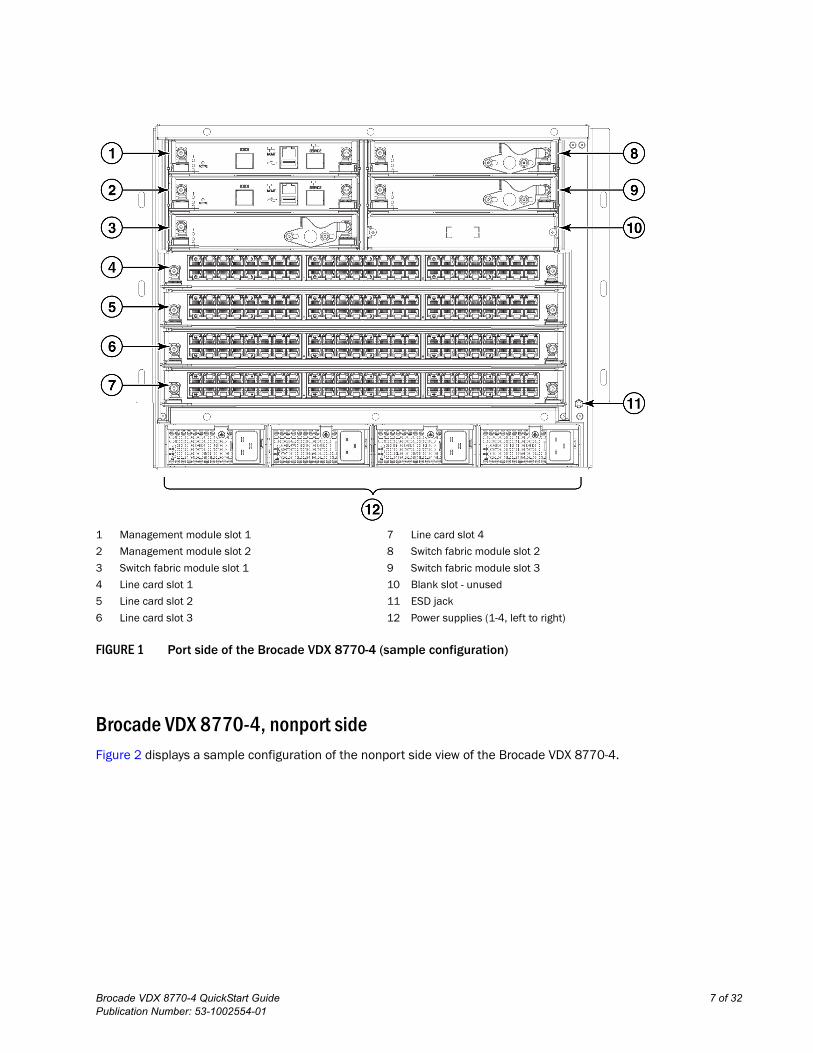
FIGURE 1 Port side of the Brocade VDX 8770-4 (sample configuration)
Brocade VDX 8770-4, nonport sideFigure 2 displays a sample configuration of the nonport side view of the Brocade VDX 8770-4.
1 Management module slot 1 7 Line card slot 4
2 Management module slot 2 8 Switch fabric module slot 2
3 Switch fabric module slot 1 9 Switch fabric module slot 3
4 Line card slot 1 10 Blank slot - unused
5 Line card slot 2 11 ESD jack
6 Line card slot 3 12 Power supplies (1-4, left to right)
Brocade VDX 8770-4 QuickStart Guide 7 of 32Publication Number: 53-1002554-01
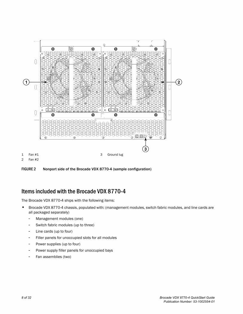
FIGURE 2 Nonport side of the Brocade VDX 8770-4 (sample configuration)
Items included with the Brocade VDX 8770-4The Brocade VDX 8770-4 ships with the following items:
• Brocade VDX 8770-4 chassis, populated with: (management modules, switch fabric modules, and line cards are all packaged separately)
- Management modules (one)
- Switch fabric modules (up to three)
- Line cards (up to four)
- Filler panels for unoccupied slots for all modules
- Power supplies (up to four)
- Power supply filler panels for unoccupied bays
- Fan assemblies (two)
1 Fan #1 3 Ground lug
2 Fan #2
8 of 32 Brocade VDX 8770-4 QuickStart GuidePublication Number: 53-1002554-01
• Accessory kit containing the following items:
- Console cable (RS-232 serial cable: The RS-232 cable has an adapter at one end that can be removed to provide an RJ-45-style connector.)
- Wrist strap (ESD grounding strap)
- Ground lug kit
- SFP extraction tool kit
- China RoHS guide
- Cable management finger assemblies
- Brocade-branded USB device
- Power cord retainer kit
- Brocade VDX 8770-4 QuickStart Guide (this publication)
- Hardware for securing the switch in a rack
- Web pointer document
- Air filter
The rack mount kits must be ordered separately.
Order the Brocade-branded transceivers (SFP, SFP+, or QSFP) and cables or direct-attach cables from your Brocade distributor. The Brocade VDX 8770-4 supports SR and LR SFP and SFP+ transceivers. The QSFP transceivers are SR transceivers only.
NOTEFor information about the transceivers that are qualified for the Brocade VDX 8770-4, refer to http://www.brocade.com/downloads/documents/matrices/Brocade_Compatibility_Matrix.pdf.
Preparing for the Brocade VDX 8770-4 installation
NOTERefer to the safety notices before installation (“Safety notices”).Refer to “Power specifications” to plan for meeting power supply standards before installing the switch.Refer to “Environmental requirements” to plan for your environmental needs.Refer to “Managing cables” to plan for cable management.
The following steps are required to ensure correct installation and operation.
1. Provide a space that is 8 rack units (8U) high, 61.19 cm (24.09 in.) deep, and 43.74 cm (17.22 in.) wide. One rack unit is equal to 4.45 cm (1.75 in.). If you are using the Air Intake Kit, you will need a space that is 10U high to accommodate both the Intake Kit and the switch.
Plan to install the Brocade VDX 8770-4 with the port side facing the air-intake aisle. Airflow is from the left side of the switch to the fan side. If you are using the Intake Air Duct rack kit for mounting the Brocade VDX 8770-4, then the airflow is from the port side to the fan side.
Ensure that the rack is balanced and mechanically secured to provide stability in the event of an earthquake and that the equipment does not exceed the rack’s weight limits.
NOTEDoorways must be wider than 91 cm (36 in.) to accommodate the switch.
Brocade VDX 8770-4 QuickStart Guide 9 of 32Publication Number: 53-1002554-01
2. Ensure that dedicated electrical branch circuits with the following characteristics are available:
• Up to four dedicated fused 200–240 VAC, 50–60 Hz feeds or -48 VDC (one per power supply)
• One cable for each power supply
CAUTION
Use a separate branch circuit for each AC power cord for redundancy in case one of the circuits fails.
• Protected by a circuit breaker in accordance with local electrical codes
• Supply circuit, line fusing, and wire size adequate to the electrical rating on the switch nameplate
• Location close to the switch and easily accessible
• Grounded outlets installed by a licensed electrician and compatible with the power cords
DANGER
If the installation requires a different power cord than the one supplied with the switch, make sure you use a power cord displaying the mark of the safety agency that defines the regulations for power cords in your country. The mark is your assurance that the power cord can be used safely with the switch.
3. Plan for cable management before installing the switch.
Cables can be managed in a variety of ways, such as by routing cables below the switch, to either side of the switch, through cable channels on the sides of the rack, or by using patch panels.
4. Ensure that the following items are available for configuration of the Brocade VDX 8770-4:
• Workstation with an installed terminal emulator, such as HyperTerminal
• Console (serial) cable (provided)
• Ethernet cables (not provided)
• Either access to an FTP server or a Brocade USB device for backing up the switch configuration or collecting supportsave output data (optional)
• Transceivers (copper and optical) and compatible cables and direct-attach cables if needed
5. Ensure that the air intake and exhaust vents have a minimum of 5.1 cm (2 in.) of airspace.
6. Ensure that the air temperature on the air intake side is less than 40°C (104°F) during operation.
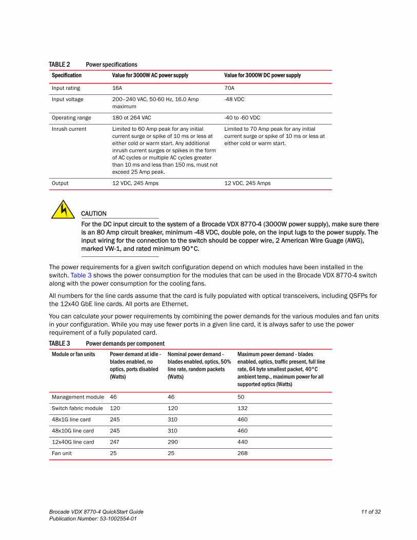
Power specifications
Power for the Brocade VDX 8770-4 can be supplied with either AC- or DC-based 3000 watt power supplies. The Brocade VDX 8770-4 has room for up to four power supplies.
Table 2 shows the basic power specifications for each power supply.
10 of 32 Brocade VDX 8770-4 QuickStart GuidePublication Number: 53-1002554-01
.
CAUTION
For the DC input circuit to the system of a Brocade VDX 8770-4 (3000W power supply), make sure there is an 80 Amp circuit breaker, minimum -48 VDC, double pole, on the input lugs to the power supply. The input wiring for the connection to the switch should be copper wire, 2 American Wire Guage (AWG), marked VW-1, and rated minimum 90°C.
The power requirements for a given switch configuration depend on which modules have been installed in the switch. Table 3 shows the power consumption for the modules that can be used in the Brocade VDX 8770-4 switch along with the power consumption for the cooling fans.
All numbers for the line cards assume that the card is fully populated with optical transceivers, including QSFPs for the 12x40 GbE line cards. All ports are Ethernet.
You can calculate your power requirements by combining the power demands for the various modules and fan units in your configuration. While you may use fewer ports in a given line card, it is always safer to use the power requirement of a fully populated card.
TABLE 2 Power specifications
Specification Value for 3000W AC power supply Value for 3000W DC power supply
Input rating 16A 70A
Input voltage 200–240 VAC, 50-60 Hz, 16.0 Amp maximum
-48 VDC
Operating range 180 ot 264 VAC -40 to -60 VDC
Inrush current Limited to 60 Amp peak for any initial current surge or spike of 10 ms or less at either cold or warm start. Any additional inrush current surges or spikes in the form of AC cycles or multiple AC cycles greater than 10 ms and less than 150 ms, must not exceed 25 Amp peak.
Limited to 70 Amp peak for any initial current surge or spike of 10 ms or less at either cold or warm start.
Output 12 VDC, 245 Amps 12 VDC, 245 Amps
TABLE 3 Power demands per component
Module or fan units Power demand at idle - blades enabled, no optics, ports disabled (Watts)
Nominal power demand - blades enabled, optics, 50% line rate, random packets (Watts)
Maximum power demand - blades enabled, optics, traffic present, full line rate, 64 byte smallest packet, 40°C ambient temp., maximum power for all supported optics (Watts)
Management module 46 46 50
Switch fabric module 120 120 132
48x1G line card 245 310 460
48x10G line card 245 310 460
12x40G line card 247 290 440
Fan unit 25 25 268
Brocade VDX 8770-4 QuickStart Guide 11 of 32Publication Number: 53-1002554-01
CAUTION
For the NEBS-compliant installation of a Brocade VDX 8770-4 with AC or DC systems, use a ground wire of at least 2 AWG. The ground wire should have an agency-approved crimped connector (provided with the device) attached to one end, with the other end attached to building ground. The connector must be crimped with the proper tool, allowing it to be connected to both ground screws on the enclosure. Before crimping the ground wire into the provided ground lug, ensure that the bare copper wire has been cleaned and antioxidant is applied to the bare wire.
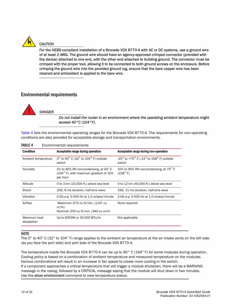
Environmental requirements
DANGER
Do not install the router in an environment where the operating ambient temperature might exceed 40°C (104°F).
Table 4 lists the environmental operating ranges for the Brocade VDX 8770-4. The requirements for non-operating conditions are also provided for acceptable storage and transportation environments.
NOTEThe 0° to 40° C (32° to 104° F) range applies to the ambient air temperature at the air intake vents on the left side (as you face the port side) and port side of the Brocade VDX 8770-4.
The temperature inside the Brocade VDX 8770-4 can be up to 90° C (194° F) for some modules during operation. Cooling policy is based on a combination of ambient temperature and measured temperature on the modules. Various combinations will result in an increase in fan speed to create more cooling in the switch. If a component approaches a critical temperature that will trigger a module shutdown, there will be a WARNING message in the raslog, followed by a CRITICAL message saying that the module will shut down in two minutes.Use the show environment command to view temperature status.
TABLE 4 Environmental requirements
Condition Acceptable range during operation Acceptable range during non-operation
Ambient temperature 0° to 40° C (32° to 104° F) outside switch
-25° to +70° C (-13° to 158° F) outside switch
Humidity 5% to 90% RH noncondensing, at 40° C (104° F), with maximum gradient of 10% per hour
10% to 90% RH noncondensing, at 70° C (158° F)
Altitude 0 to 3 km (10,000 ft.) above sea level 0 to 12 km (40,000 ft.) above sea level
Shock 20G, 6 ms duration, half-sine wave 33G, 11 ms duration, half-sine wave
Vibration 0.5G p-p, 5-500 Hz at 1.0 octave/minute 2.0G p-p, 5-500 Hz at 1.0 octave/minute
Airflow Maximum: 675 cu ft/min. (1147 cu m/hr)Nominal: 200 cu ft/min. (340 cu m/hr
None required
Maximum heat dissipation
Up to 6000W or 20,500 BTU/hr Not applicable
12 of 32 Brocade VDX 8770-4 QuickStart GuidePublication Number: 53-1002554-01
Switch slots
Switch slots are coded and numbered to differentiate between management module slots, switch fabric module slots, and line card slots. Management modules (MM) must be installed only in slots M1 and M2. Switch fabric modules (SFM) must be installed only in slots S1 through S3. There must be at least one SFM installed in either slot S1 or slot S2. The line card slots, L1 through L4, can be filled with either 48x1G, 48x10G, or 12x40G line cards. Unused slots must be filled with the correct filler panels to maintain adequate cooling.
Unpacking and installing the Brocade VDX 8770-4Use the following procedure to unpack and install your Brocade VDX 8770-4.
CAUTION
Use safe lifting practices when moving the product. (C015)
NOTEA fully populated Brocade VDX 8770-4 weighs approximately 86.18 kg (190 lb) and requires a hydraulic or assisted lift to install it.
1. Unpack the Brocade VDX 8770-4.
a. Cut the bands that encircle the packaging.
b. Slide the upper portion of the cardboard shipping box up off the pallet and shipping tray.
NOTEThe Brocade VDX 8770-4 packaging incorporates a wood pallet and brackets. The switch sits on top of a corrugated cardboard shipping tray.
c. Save the packing materials for use when returning a switch.
d. Leave the switch on top of the shipping tray and pallet if the switch must be transported to the installation location.
2. Use a pallet jack or other assisted lift to transport the new switch to the installation area.
3. Using the rack mount instructions, install the rack components in the rack and mounting flanges on the switch. The rack mount kit and instructions are shipped separately from the switch.
4. Remove the accessory kit (cardboard box), packing foam, and antistatic plastic from the switch and set them aside.
5. Remove the foam inserts around the base of the switch.
6. Use a lift to raise the switch to the correct level. If installing the switch in a rack, follow the instructions provided by the rack kit manufacturer.
7. If applicable, lock the wheels of the lift.
8. Ensure that the switch is oriented so that the left side and port side (front) have access to intake air.
9. Gently slide the switch onto the final installation surface, ensuring that it remains supported during the transfer.
Brocade VDX 8770-4 QuickStart Guide 13 of 32Publication Number: 53-1002554-01
10. Before you apply power to the switch, you can install the MM, SFM, and line card modules as well as power supplies to speed up your installation. Refer to the following tasks for information on inserting thet various modules.
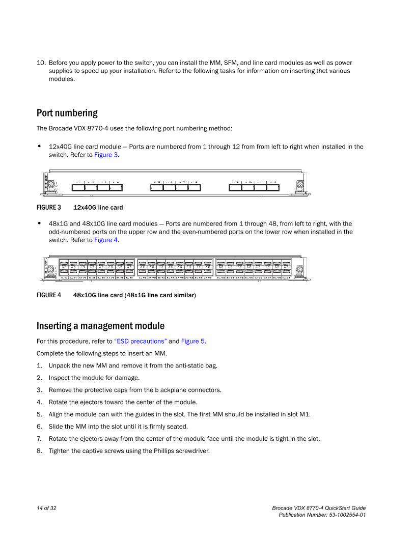
Port numberingThe Brocade VDX 8770-4 uses the following port numbering method:
• 12x40G line card module — Ports are numbered from 1 through 12 from from left to right when installed in the switch. Refer to Figure 3.
FIGURE 3 12x40G line card
• 48x1G and 48x10G line card modules — Ports are numbered from 1 through 48, from left to right, with the odd-numbered ports on the upper row and the even-numbered ports on the lower row when installed in the switch. Refer to Figure 4.
FIGURE 4 48x10G line card (48x1G line card similar)
Inserting a management moduleFor this procedure, refer to “ESD precautions” and Figure 5.
Complete the following steps to insert an MM.
1. Unpack the new MM and remove it from the anti-static bag.
2. Inspect the module for damage.
3. Remove the protective caps from the b ackplane connectors.
4. Rotate the ejectors toward the center of the module.
5. Align the module pan with the guides in the slot. The first MM should be installed in slot M1.
6. Slide the MM into the slot until it is firmly seated.
7. Rotate the ejectors away from the center of the module face until the module is tight in the slot.
8. Tighten the captive screws using the Phillips screwdriver.
14 of 32 Brocade VDX 8770-4 QuickStart GuidePublication Number: 53-1002554-01
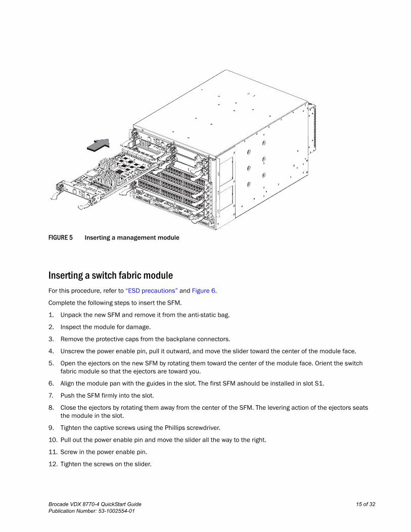
FIGURE 5 Inserting a management module
Inserting a switch fabric moduleFor this procedure, refer to “ESD precautions” and Figure 6.
Complete the following steps to insert the SFM.
1. Unpack the new SFM and remove it from the anti-static bag.
2. Inspect the module for damage.
3. Remove the protective caps from the backplane connectors.
4. Unscrew the power enable pin, pull it outward, and move the slider toward the center of the module face.
5. Open the ejectors on the new SFM by rotating them toward the center of the module face. Orient the switch fabric module so that the ejectors are toward you.
6. Align the module pan with the guides in the slot. The first SFM ashould be installed in slot S1.
7. Push the SFM firmly into the slot.
8. Close the ejectors by rotating them away from the center of the SFM. The levering action of the ejectors seats the module in the slot.
9. Tighten the captive screws using the Phillips screwdriver.
10. Pull out the power enable pin and move the slider all the way to the right.
11. Screw in the power enable pin.
12. Tighten the screws on the slider.
Brocade VDX 8770-4 QuickStart Guide 15 of 32Publication Number: 53-1002554-01
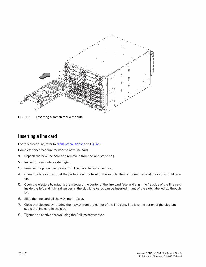
FIGURE 6 Inserting a switch fabric module
Inserting a line cardFor this procedure, refer to “ESD precautions” and Figure 7.
Complete this procedure to insert a new line card.
1. Unpack the new line card and remove it from the anti-static bag.
2. Inspect the module for damage.
3. Remove the protective covers from the backplane connectors.
4. Orient the line card so that the ports are at the front of the switch. The component side of the card should face up.
5. Open the ejectors by rotating them toward the center of the line card face and align the flat side of the line card inside the left and right rail guides in the slot. Line cards can be inserted in any of the slots labelled L1 through L4.
6. Slide the line card all the way into the slot.
7. Close the ejectors by rotating them away from the center of the line card. The levering action of the ejectors seats the line card in the slot.
8. Tighten the captive screws using the Phillips screwdriver.
16 of 32 Brocade VDX 8770-4 QuickStart GuidePublication Number: 53-1002554-01
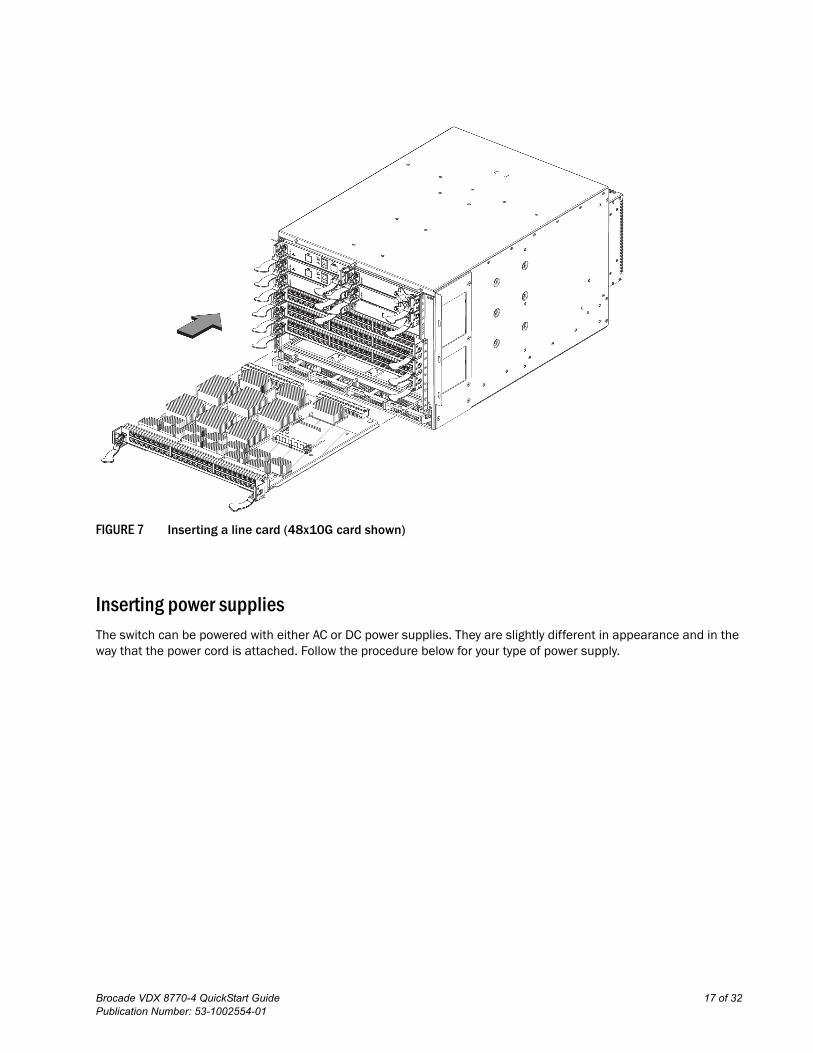
FIGURE 7 Inserting a line card (48x10G card shown)
Inserting power suppliesThe switch can be powered with either AC or DC power supplies. They are slightly different in appearance and in the way that the power cord is attached. Follow the procedure below for your type of power supply.
Brocade VDX 8770-4 QuickStart Guide 17 of 32Publication Number: 53-1002554-01
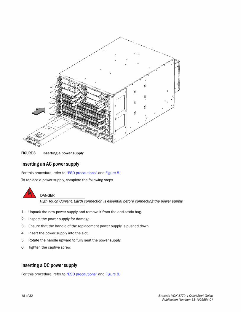
FIGURE 8 Inserting a power supply
Inserting an AC power supply
For this procedure, refer to “ESD precautions” and Figure 8.
To replace a power supply, complete the following steps.
DANGER
High Touch Current. Earth connection is essential before connecting the power supply.
1. Unpack the new power supply and remove it from the anti-static bag.
2. Inspect the power supply for damage.
3. Ensure that the handle of the replacement power supply is pushed down.
4. Insert the power supply into the slot.
5. Rotate the handle upward to fully seat the power supply.
6. Tighten the captive screw.
Inserting a DC power supply
For this procedure, refer to “ESD precautions” and Figure 8.
18 of 32 Brocade VDX 8770-4 QuickStart GuidePublication Number: 53-1002554-01
To replace a DC power supply, complete the following steps.
1. Unpack the new power supply and remove it from the anti-static bag.
2. Inspect the power supply for damage.
3. Use a #1 Phillips screwdriver to remove the screw that secures the safety cover over the power lugs. Remove the safety cover.
4. Ensure that the handle of the replacement power supply is rotated down.
5. Insert the power supply into the slot.
6. Rotate the handle upward to fully seat the power supply.
7. Tighten the captive screw.
ATTENTIONThis equipment installation must meet NEC/CEC code requirements. Consult local authorities for regulations.
Providing power to the Brocade VDX 8770-4Complete the following steps to provide power to the chassis. Each power supply has one power cord.
DANGER
Use the supplied power cords. Ensure the facility power receptacle is the correct type, supplies the required voltage, and is properly grounded. (D004)
Connecting an AC power cord
1. Plug the power cord into the power supply.
2. Route the cable so it will be out of the way when connected to the power source.
3. Plug the other end of the cable into the power source.
Connecting a DC power cord
1. Use a #1 Phillips screwdriver to remove the screw that secures the safety cover over the power lugs and remove the safety cover.
2. Use a #2 Phillips screwdriver to unscrew the power lugs.
3. Crimp the #2 AWG power supply wires into the power lugs.
4. Connect the power lugs to the power supply unit.
Connect the -48V wire to the negative terminal and the 0V wire to the positive terminal.
NOTEThe DC return must be isolated from the chassis ground (DC-I) when making connections to the connections to the power supply.
5. Replace the safety cover.
Brocade VDX 8770-4 QuickStart Guide 19 of 32Publication Number: 53-1002554-01
6. Plug the other end of the cable into the power source.
ATTENTIONDo not connect the switch to the network until the IP addresses are configured.
Preparing to configure the Brocade VDX 8770-4The Brocade VDX 8770-4 must be configured before it is connected to the fabric, and all of the configuration commands must be entered through the active MM. The Brocade VDX 8770-4 configuration includes the following parameters:
• RBridge ID, If you are going to have more than one switch in a fabric.
• IP address and gateway address for the switch
• IP addresses, host names, and gateway addresses for one or two MMs, as needed
• Host name
You also need to change passwords from their default values and set the time and date, either via NTP or manually.
In order to retain the changes made during configuration you will have to copy the running configuration file to the startup configuration file. This will ensure that the switch reboots to your preferred configuration.
The configuration information is mirrored to the standby MM, if you have installed one, which allows the current configuration to remain available even if the active MM fails. The configuration information for the Brocade VDX 8770-4 is stored in the CID cards and the flash memory of the MMs. The configuration can be backed up to a workstation (uploaded) and then downloaded to the active MM if necessary.
By default, the Brocade VDX 8770-4 is in VCS™ mode. It cannot be configured in standalone mode. Without a VCS license, the switch can be part of a two-node cluster where two switches are connected in VCS mode to form an Ethernet fabric. To be part of a larger cluster, you must install a VCS license.
In VCS mode, the switch is part of an Ethernet fabric involving two or more VCS-enabled switches. VCS technology embodies the concept of distributed intelligence. Distributed intelligence means that all configuration and destination information is automatically distributed to each member switch in the fabric. Distributed intelligence has three major characteristics:
• The fabric is self-forming. When two or more VCS-enabled switches with unique Rbridge IDs are connected to form an Ethernet fabric, the fabric is automatically created and the switches discover the common fabric configuration.
• The fabric is masterless. No single switch stores configuration information or controls fabric operations. Any switch can fail or be removed without causing disruptive fabric downtime or delayed traffic.
• The fabric is aware of all members, devices, and Virtual Machines (VMs). Automatic Migration of Port Profiles (AMPP) supports VM migration to another physical server. If the VM moves, it is automatically reconnected to all of its original resources.
Establishing a serial connection to the Brocade VDX 8770-4The serial port is located on the port side of the Brocade VDX 8770-4. The switch uses an RJ-45 connector for the serial port. An RJ-45 to DB9 adapter is also provided with the Brocade VDX 8770-4. The cable supplied with the switch is a rollover cable. The serial port is used to connect to a workstation to configure the Brocade VDX 8770-4 IP address before connecting the switch to a fabric or IP network.
20 of 32 Brocade VDX 8770-4 QuickStart GuidePublication Number: 53-1002554-01
NOTETo protect the serial port from damage, keep the cover on the port when not in use.
To establish a serial connection to the serial (console) port on the Brocade VDX 8770-4, complete the following steps.
1. Verify that the Brocade VDX 8770-4 is powered on and that POST is complete by verifying that all power LED indicators on the management, switch fabric, and line card modules display a steady green light.
2. Remove the shipping cap from the serial port (labeled I0I0I) on the active MM. By default, the MM installed in slot M1 is the active MM unless an error occurs. The active MM is also indicated by an illuminated green LED labeled ACTIVE.
3. Use the serial cable provided with the Brocade VDX 8770-4 to connect the serial port on the active MM to a computer workstation.
If the serial port on the workstation or terminal device is DB9 instead of RJ-45, remove the adapter on the end of the serial cable and insert the exposed DB9 connector into the DB9 serial port on the workstation.
ATTENTIONThe serial port is intended primarily for the initial setting of the IP address and for service purposes.
4. Disable any serial communication programs running on the workstation (such as synchronization programs).
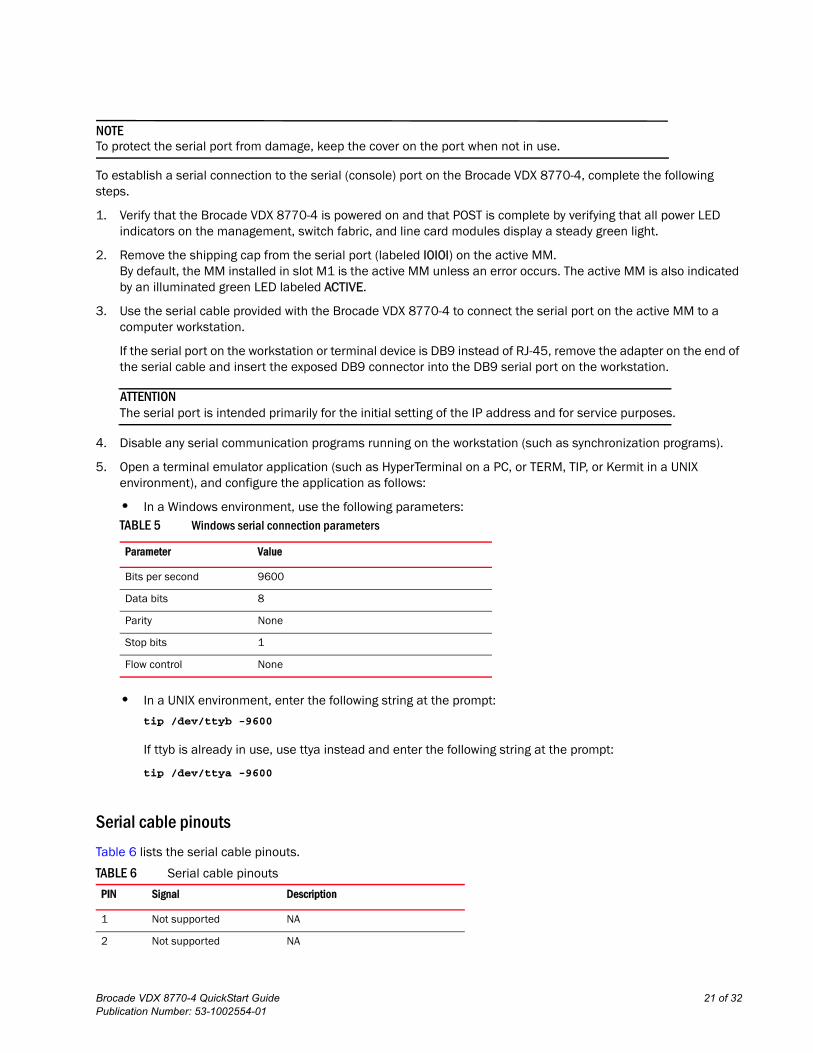
5. Open a terminal emulator application (such as HyperTerminal on a PC, or TERM, TIP, or Kermit in a UNIX environment), and configure the application as follows:
• In a Windows environment, use the following parameters:
• In a UNIX environment, enter the following string at the prompt:
tip /dev/ttyb -9600
If ttyb is already in use, use ttya instead and enter the following string at the prompt:
tip /dev/ttya -9600
Serial cable pinouts
Table 6 lists the serial cable pinouts.
TABLE 5 Windows serial connection parameters
Parameter Value
Bits per second 9600
Data bits 8
Parity None
Stop bits 1
Flow control None
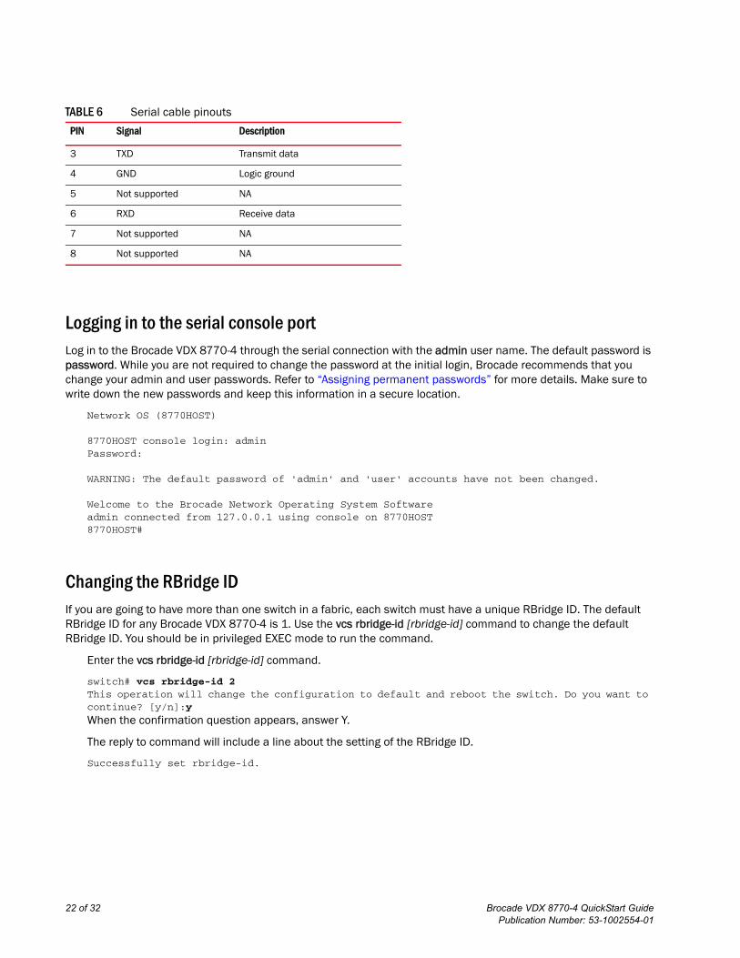
TABLE 6 Serial cable pinouts
PIN Signal Description
1 Not supported NA
2 Not supported NA
Brocade VDX 8770-4 QuickStart Guide 21 of 32Publication Number: 53-1002554-01
Logging in to the serial console portLog in to the Brocade VDX 8770-4 through the serial connection with the admin user name. The default password is password. While you are not required to change the password at the initial login, Brocade recommends that you change your admin and user passwords. Refer to “Assigning permanent passwords” for more details. Make sure to write down the new passwords and keep this information in a secure location.
Network OS (8770HOST)
8770HOST console login: adminPassword:
WARNING: The default password of 'admin' and 'user' accounts have not been changed.
Welcome to the Brocade Network Operating System Softwareadmin connected from 127.0.0.1 using console on 8770HOST8770HOST#
Changing the RBridge IDIf you are going to have more than one switch in a fabric, each switch must have a unique RBridge ID. The default RBridge ID for any Brocade VDX 8770-4 is 1. Use the vcs rbridge-id [rbridge-id] command to change the default RBridge ID. You should be in privileged EXEC mode to run the command.
Enter the vcs rbridge-id [rbridge-id] command.
switch# vcs rbridge-id 2This operation will change the configuration to default and reboot the switch. Do you want to continue? [y/n]:y
When the confirmation question appears, answer Y.
The reply to command will include a line about the setting of the RBridge ID.
Successfully set rbridge-id.
3 TXD Transmit data
4 GND Logic ground
5 Not supported NA
6 RXD Receive data
7 Not supported NA
8 Not supported NA
TABLE 6 Serial cable pinouts
PIN Signal Description
22 of 32 Brocade VDX 8770-4 QuickStart GuidePublication Number: 53-1002554-01
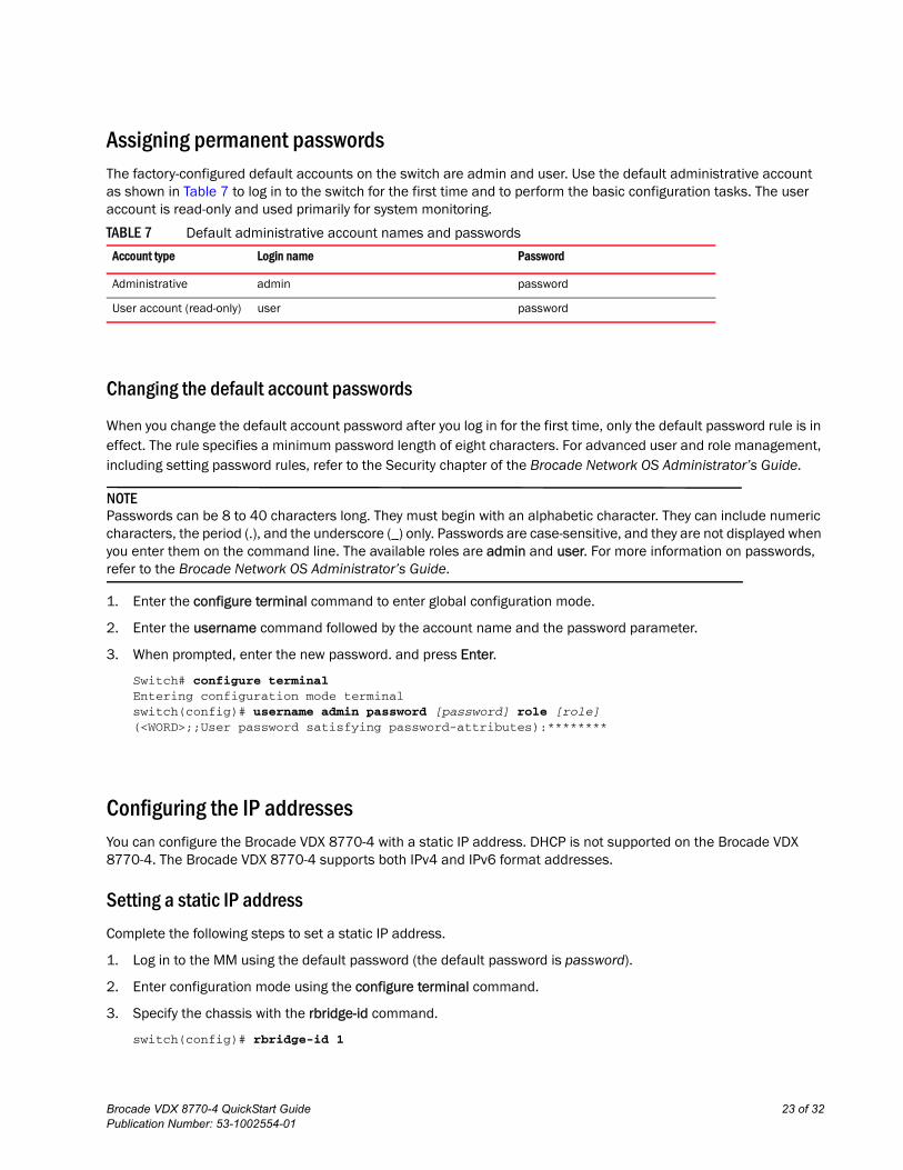
Assigning permanent passwordsThe factory-configured default accounts on the switch are admin and user. Use the default administrative account as shown in Table 7 to log in to the switch for the first time and to perform the basic configuration tasks. The user account is read-only and used primarily for system monitoring.
Changing the default account passwords
When you change the default account password after you log in for the first time, only the default password rule is in effect. The rule specifies a minimum password length of eight characters. For advanced user and role management, including setting password rules, refer to the Security chapter of the Brocade Network OS Administrator’s Guide.
NOTEPasswords can be 8 to 40 characters long. They must begin with an alphabetic character. They can include numeric characters, the period (.), and the underscore (_) only. Passwords are case-sensitive, and they are not displayed when you enter them on the command line. The available roles are admin and user. For more information on passwords, refer to the Brocade Network OS Administrator’s Guide.
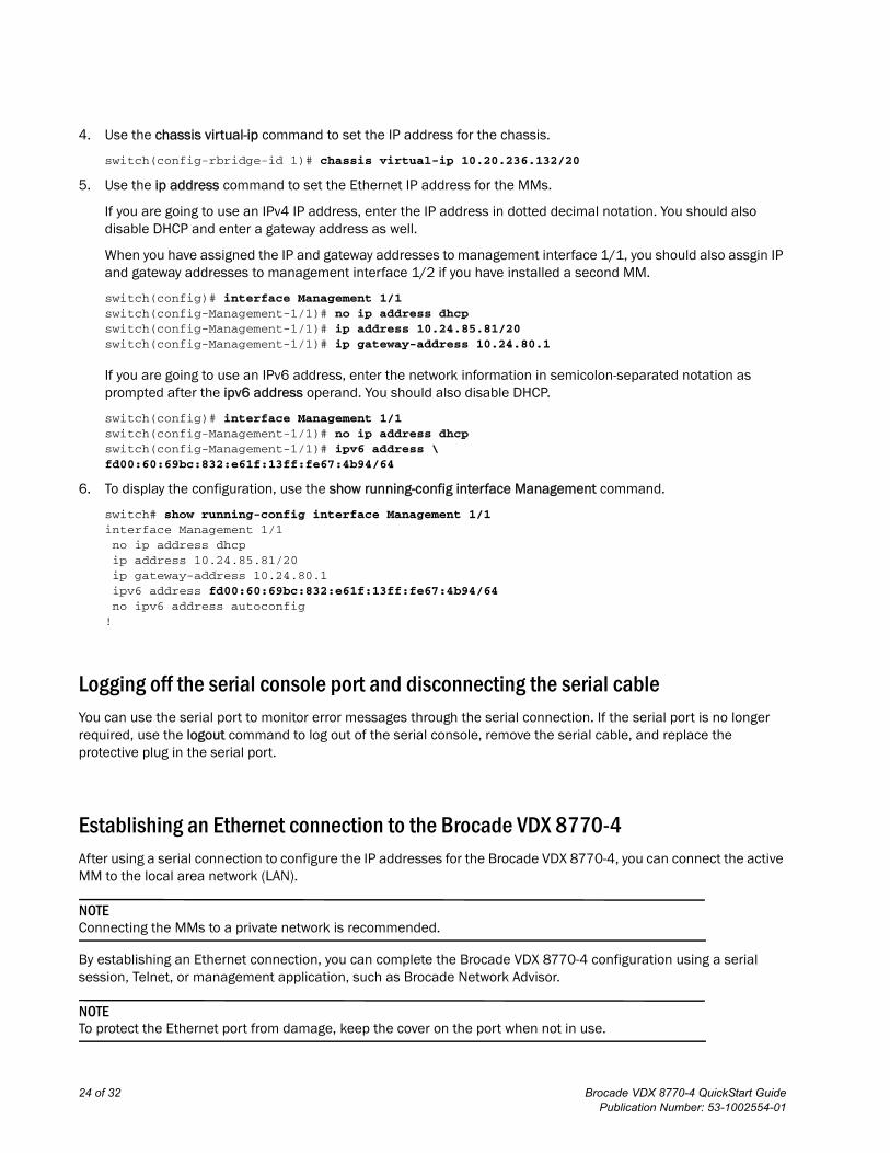
1. Enter the configure terminal command to enter global configuration mode.
2. Enter the username command followed by the account name and the password parameter.
3. When prompted, enter the new password. and press Enter.
Switch# configure terminalEntering configuration mode terminalswitch(config)# username admin password [password] role [role](<WORD>;;User password satisfying password-attributes):********
Configuring the IP addressesYou can configure the Brocade VDX 8770-4 with a static IP address. DHCP is not supported on the Brocade VDX 8770-4. The Brocade VDX 8770-4 supports both IPv4 and IPv6 format addresses.
Setting a static IP address
Complete the following steps to set a static IP address.
1. Log in to the MM using the default password (the default password is password).
2. Enter configuration mode using the configure terminal command.
3. Specify the chassis with the rbridge-id command.
switch(config)# rbridge-id 1
TABLE 7 Default administrative account names and passwords
Account type Login name Password
Administrative admin password
User account (read-only) user password
Brocade VDX 8770-4 QuickStart Guide 23 of 32Publication Number: 53-1002554-01
4. Use the chassis virtual-ip command to set the IP address for the chassis.
switch(config-rbridge-id 1)# chassis virtual-ip 10.20.236.132/20
5. Use the ip address command to set the Ethernet IP address for the MMs.
If you are going to use an IPv4 IP address, enter the IP address in dotted decimal notation. You should also disable DHCP and enter a gateway address as well.
When you have assigned the IP and gateway addresses to management interface 1/1, you should also assgin IP and gateway addresses to management interface 1/2 if you have installed a second MM.
switch(config)# interface Management 1/1switch(config-Management-1/1)# no ip address dhcpswitch(config-Management-1/1)# ip address 10.24.85.81/20switch(config-Management-1/1)# ip gateway-address 10.24.80.1
If you are going to use an IPv6 address, enter the network information in semicolon-separated notation as prompted after the ipv6 address operand. You should also disable DHCP.
switch(config)# interface Management 1/1switch(config-Management-1/1)# no ip address dhcpswitch(config-Management-1/1)# ipv6 address \fd00:60:69bc:832:e61f:13ff:fe67:4b94/64
6. To display the configuration, use the show running-config interface Management command.
switch# show running-config interface Management 1/1interface Management 1/1no ip address dhcpip address 10.24.85.81/20ip gateway-address 10.24.80.1ipv6 address fd00:60:69bc:832:e61f:13ff:fe67:4b94/64no ipv6 address autoconfig
!
Logging off the serial console port and disconnecting the serial cableYou can use the serial port to monitor error messages through the serial connection. If the serial port is no longer required, use the logout command to log out of the serial console, remove the serial cable, and replace the protective plug in the serial port.
Establishing an Ethernet connection to the Brocade VDX 8770-4After using a serial connection to configure the IP addresses for the Brocade VDX 8770-4, you can connect the active MM to the local area network (LAN).
NOTEConnecting the MMs to a private network is recommended.
By establishing an Ethernet connection, you can complete the Brocade VDX 8770-4 configuration using a serial session, Telnet, or management application, such as Brocade Network Advisor.
NOTETo protect the Ethernet port from damage, keep the cover on the port when not in use.
24 of 32 Brocade VDX 8770-4 QuickStart GuidePublication Number: 53-1002554-01
Perform the following steps to establish an Ethernet connection to the Brocade VDX 8770-4.
1. Remove the shipping plug from the Ethernet port on the active MM.
2. Insert one end of an Ethernet cable into the Ethernet port.
3. Connect the other end to an Ethernet 10/100/1000 BaseT LAN.
The Brocade VDX 8770-4 can be accessed through a remote connection using the command line by way of Telnet or any of the management tools, such as Brocade Network Advisor.
4. To complete any additional Brocade VDX 8770-4 configuration procedures through a Telnet session, log in to the Brocade VDX 8770-4 by Telnet using the admin login. The default password is password.
Customizing a host nameThis procedure is optional.
While still in Telnet you can change the host (switch) name of the switch. The host name of the Brocade VDX 8770-4 can be up to 30 characters long using Network OS release 3.0.0 or later, can include letters, numbers, hyphens, and underscore characters, and must begin with a letter. The default host name is “sw0.” The host name is displayed at the system prompt.
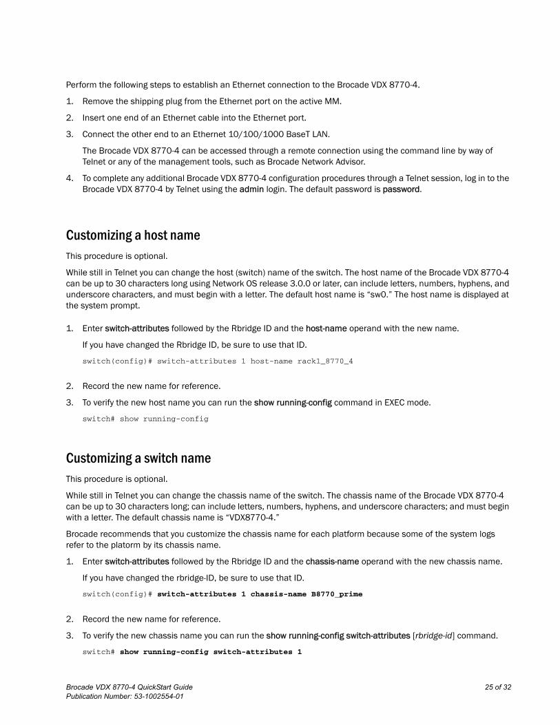
1. Enter switch-attributes followed by the Rbridge ID and the host-name operand with the new name.
If you have changed the Rbridge ID, be sure to use that ID.
switch(config)# switch-attributes 1 host-name rack1_8770_4
2. Record the new name for reference.
3. To verify the new host name you can run the show running-config command in EXEC mode.
switch# show running-config
Customizing a switch nameThis procedure is optional.
While still in Telnet you can change the chassis name of the switch. The chassis name of the Brocade VDX 8770-4 can be up to 30 characters long; can include letters, numbers, hyphens, and underscore characters; and must begin with a letter. The default chassis name is “VDX8770-4.”
Brocade recommends that you customize the chassis name for each platform because some of the system logs refer to the platorm by its chassis name.
1. Enter switch-attributes followed by the Rbridge ID and the chassis-name operand with the new chassis name.
If you have changed the rbridge-ID, be sure to use that ID.
switch(config)# switch-attributes 1 chassis-name B8770_prime
2. Record the new name for reference.
3. To verify the new chassis name you can run the show running-config switch-attributes [rbridge-id] command.
switch# show running-config switch-attributes 1
Brocade VDX 8770-4 QuickStart Guide 25 of 32Publication Number: 53-1002554-01

Setting the date and timeThe MM maintains the current date and time inside a battery-backed real-time clock (RTC) circuit. Date and time are used for logging events. Switch operation does not depend on the date and time; a Brocade VDX 8770-4 with an incorrect date and time value functions properly. Because the date and time are used for logging, error detection, and troubleshooting, you should set them correctly.
Time zones
You can set the time zone for a switch by using the clock TimeZone command. The time zone setting has the following characteristics:
• The time zone setting automatically adjusts for Daylight Savings Time.
• Changing the time zone on a switch updates the local time zone setup and is reflected in local time calculations.
• By default, all switches are in the Greenwich Mean Time (GMT) time zone (0,0). If all switches in a fabric are in one time zone, it is possible for you to keep the time zone setup at the default setting.
• System services that have already started will reflect the time zone changes only after the next reboot.
• Time zone settings persist across failover for high availability.
• Time zone settings are not affected by Network Time Protocol (NTP) server synchronization.
The following regions are supported: Africa, America, Arctic, Antarctica, Asia, Atlantic, Australia, Europe, Indian, and Pacific. One of these, along with a city name, establishes the time zone. Refer to “Setting the time zone.”
Time synchronization
To keep the time in your network current, it is recommended that the principal switch has its time synchronized with at least one external NTP server. The other switches in the fabric will automatically take their time from the principal switch.
All switches in the fabric maintain the current clock server value in nonvolatile memory. By default, this value is the local clock server of the principal switch. Changes to the clock server value on the principal switch are propagated to all switches in the fabric.
When a new switch enters the fabric, the time server daemon of the principal switch sends out the addresses of all existing clock servers and the time to the new switch.
The ntp server command accepts multiple server addresses in either IPv4 or IPv6 format. When multiple NTP server addresses are passed, ntp server sets the first obtainable address as the active NTP server. If there are no reachable time servers, then the local switch time is the default time.
Synchronizing local time using NTP
Perform the following steps to synchronize the local time using NTP.
1. Log in to the switch using the default password (the default password is password).
2. Enter configure terminal to change to global configuration mode.
26 of 32 Brocade VDX 8770-4 QuickStart GuidePublication Number: 53-1002554-01
switch# configure terminalEntering configuration mode terminal
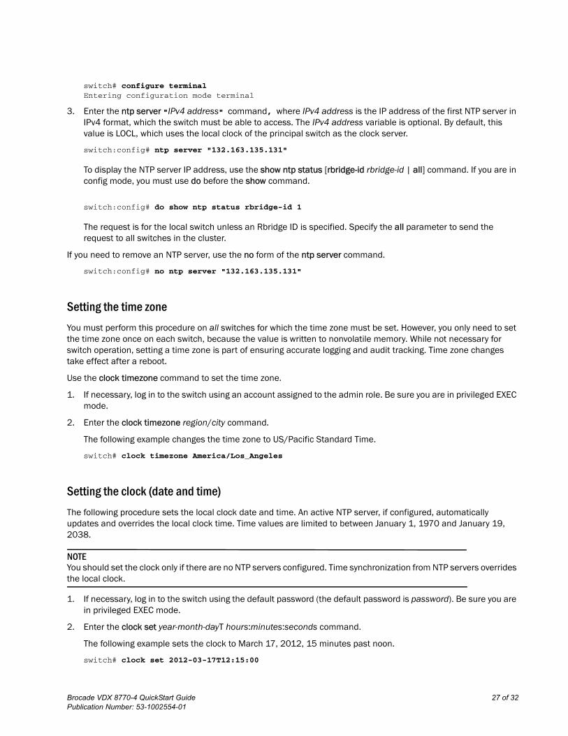
3. Enter the ntp server "IPv4 address" command, where IPv4 address is the IP address of the first NTP server in IPv4 format, which the switch must be able to access. The IPv4 address variable is optional. By default, this value is LOCL, which uses the local clock of the principal switch as the clock server.
switch:config# ntp server "132.163.135.131"
To display the NTP server IP address, use the show ntp status [rbridge-id rbridge-id | all] command. If you are in config mode, you must use do before the show command.
switch:config# do show ntp status rbridge-id 1
The request is for the local switch unless an Rbridge ID is specified. Specify the all parameter to send the request to all switches in the cluster.
If you need to remove an NTP server, use the no form of the ntp server command.
switch:config# no ntp server "132.163.135.131"
Setting the time zone
You must perform this procedure on all switches for which the time zone must be set. However, you only need to set the time zone once on each switch, because the value is written to nonvolatile memory. While not necessary for switch operation, setting a time zone is part of ensuring accurate logging and audit tracking. Time zone changes take effect after a reboot.
Use the clock timezone command to set the time zone.
1. If necessary, log in to the switch using an account assigned to the admin role. Be sure you are in privileged EXEC mode.
2. Enter the clock timezone region/city command.
The following example changes the time zone to US/Pacific Standard Time.
switch# clock timezone America/Los_Angeles
Setting the clock (date and time)
The following procedure sets the local clock date and time. An active NTP server, if configured, automatically updates and overrides the local clock time. Time values are limited to between January 1, 1970 and January 19, 2038.
NOTEYou should set the clock only if there are no NTP servers configured. Time synchronization from NTP servers overrides the local clock.
1. If necessary, log in to the switch using the default password (the default password is password). Be sure you are in privileged EXEC mode.
2. Enter the clock set year-month-dayT hours:minutes:seconds command.
The following example sets the clock to March 17, 2012, 15 minutes past noon.
switch# clock set 2012-03-17T12:15:00
Brocade VDX 8770-4 QuickStart Guide 27 of 32Publication Number: 53-1002554-01
If you want to show the clock and time zone settings, use the show clock [rbridge-id rbridge-id | all] command.
switch# show clock
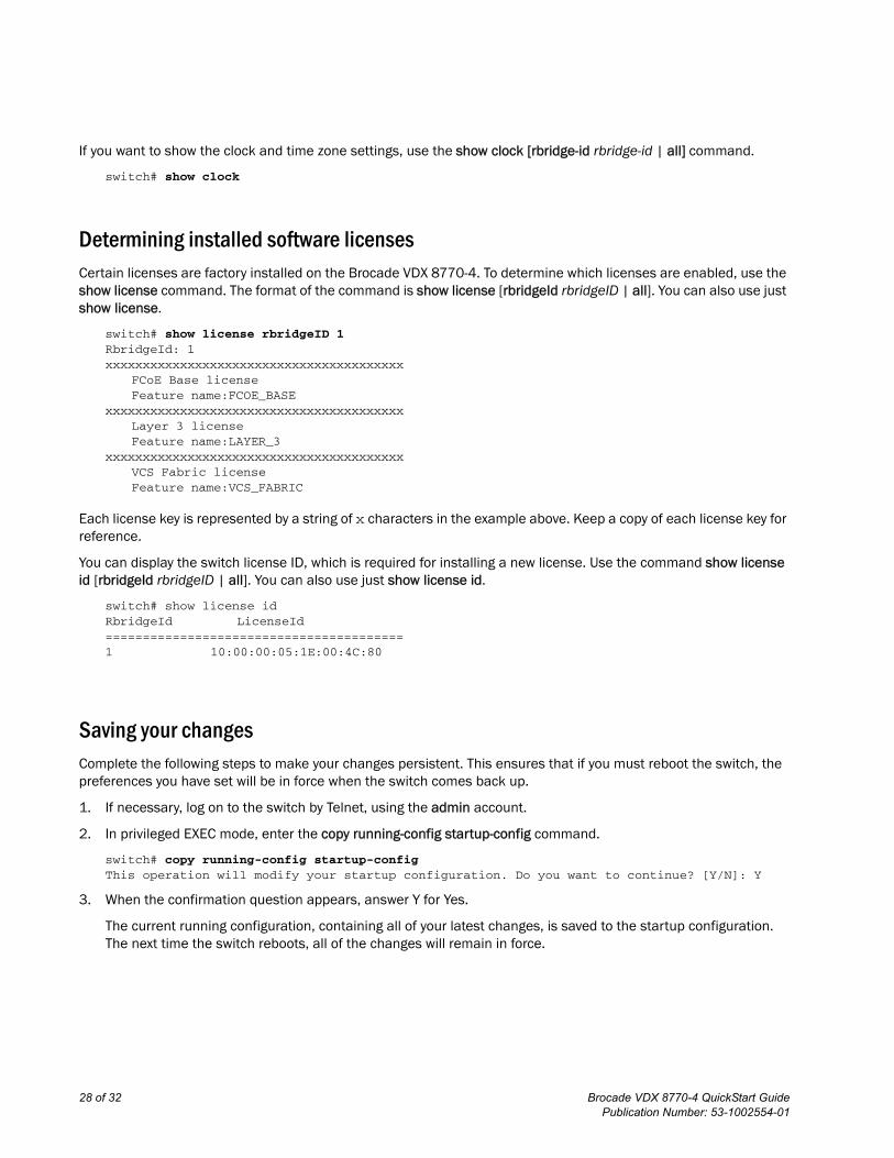
Determining installed software licensesCertain licenses are factory installed on the Brocade VDX 8770-4. To determine which licenses are enabled, use the show license command. The format of the command is show license [rbridgeId rbridgeID | all]. You can also use just show license.
switch# show license rbridgeID 1RbridgeId: 1xxxxxxxxxxxxxxxxxxxxxxxxxxxxxxxxxxxxxxxx
FCoE Base licenseFeature name:FCOE_BASE
xxxxxxxxxxxxxxxxxxxxxxxxxxxxxxxxxxxxxxxxLayer 3 licenseFeature name:LAYER_3
xxxxxxxxxxxxxxxxxxxxxxxxxxxxxxxxxxxxxxxxVCS Fabric licenseFeature name:VCS_FABRIC
Each license key is represented by a string of x characters in the example above. Keep a copy of each license key for reference.
You can display the switch license ID, which is required for installing a new license. Use the command show license id [rbridgeId rbridgeID | all]. You can also use just show license id.
switch# show license idRbridgeId LicenseId========================================1 10:00:00:05:1E:00:4C:80
Saving your changesComplete the following steps to make your changes persistent. This ensures that if you must reboot the switch, the preferences you have set will be in force when the switch comes back up.
1. If necessary, log on to the switch by Telnet, using the admin account.
2. In privileged EXEC mode, enter the copy running-config startup-config command.
switch# copy running-config startup-configThis operation will modify your startup configuration. Do you want to continue? [Y/N]: Y
3. When the confirmation question appears, answer Y for Yes.
The current running configuration, containing all of your latest changes, is saved to the startup configuration. The next time the switch reboots, all of the changes will remain in force.
28 of 32 Brocade VDX 8770-4 QuickStart GuidePublication Number: 53-1002554-01
Verifying correct operationComplete the following steps to verify correct operation for the Brocade VDX 8770-4.
1. Check the LEDs to verify that all components are functional.
2. If necessary, log in to the switch by Telnet, using the admin account.
3. Enter the show chassis command to verify that the Brocade VDX 8770-4 and its components are operating correctly.
4. Enter the show interface command to show the status of all of the ports in the line cards.
5. Enter the show fabric all command to verify the operation of the Brocade VDX 8770-4 in the fabric.
Backing up the configurationComplete the following steps to back up the configuration for the Brocade VDX 8770-4. If you back up your configuration to a USB device, be sure to use a Brocade-branded USB device. The Brocade USB device comes pre-configured with four directories, /firmware, /config, /support, and /firmwarekey. Configuration backups are automatically saved in the /config directory.
1. If necessary, log on to the switch by Telnet, using the admin account.
2. You can choose to back up the the startup configuration or the running configuration or both. To back up these configurations, use the copy command. These examples show backing up the configurations to a Brocade-branded USB device.
a. Insert the Brocade-branded USB device into the USB port on the active management module.
b. Enable the USB device by entering the USB on command.
c. To back up the startup configuration, enter copy startup-config usb://mystartupconfigdate.
The date portion of the target file name should be the current date to indicate when the backup was made. For example: copy running-config usb://myrunningconfig06142012.
d. To back up the running configuration, enter copy running-config usb://myrunningconfigdate.
Alternatively, you can save the configuration files to a remote host using either FTP or SCP. The destination file argument would be either ftp://username:password@host_ip_address/path/filename or scp://username:password@host_ip_address/path/filename respectively. Specifying a path is optional. As with the USB examples, be sure to append the date to the target file name.
ATTENTIONPasswords are not saved in the configuration file, and are not uploaded during a configuration upload.
NOTEBrocade recommends that the configuration be backed up on a regular basis to ensure that a complete configuration is available for downloading to a replacement management module or Brocade VDX 8770-4. Be sure to append the date to the end of the target file names to make it clear which are the latest backups.
Brocade VDX 8770-4 QuickStart Guide 29 of 32Publication Number: 53-1002554-01
Connecting network devicesYou can connect your switch to a variety of network devices. Refer to the topics below for some specific requirements for making these connections.
Connecting to Ethernet devices
For copper connections to a 10/100Base-TX or 1000Base-T switch or another Brocade device, a crossover cable is required.
NOTEThe 802.3ab standard (automatic MDI or MDIX detection) calls for automatic negotiation of the connection between two 1000Base-T ports. Therefore, a crossover cable may not be required; a straight-through cable may work as well.
Connecting to workstations, servers, or routers
Straight-through unshielded twisted pair (UTP) cabling is required for direct UTP attachment to workstations, servers, or routers using network interface cards (NICs).
Fiber cabling is required for direct attachment to Gigabit NICs or switches and routers through fiber ports.
Connecting a network device to a fiber port
For direct attachment from the Brocade device to a Gigabit NIC, switch, or router, fiber cabling with an LC connector is required.
Testing connectivity
After you install the network cables, you can test network connectivity to other devices by observing the LEDs related to network connection and performing trace routes.
Installing transceivers and attaching cablesThe following sets of steps cover the installation of transceivers and cables for most SFP and QSFP transceivers.
Installing SFP and SFP+ transceivers and cables
Complete the following steps to install SFP and SFP+ transceivers.
If you are implementing Brocade trunks, be aware that trunking is supported only on the 48x10GbE line card. The port groups can consist of up to 8 ports. The octet groups are ports 1-8, 9-16, 17-24, 25-32, 33-40, and 41-48.
1. Add the transceivers and cables to the line card ports.
Position one of the optical transceivers so that the key is oriented correctly to the port. Insert the transceiver into the port until it is firmly seated and the latching mechanism clicks.
30 of 32 Brocade VDX 8770-4 QuickStart GuidePublication Number: 53-1002554-01
Transceivers are keyed so that they can only be inserted with the correct orientation. If a transceiver does not slide in easily, ensure that it is correctly oriented.
2. Position a cable so that the key (the ridge on one side of the cable connector) is aligned with the slot in the transceiver. Insert the cable into the transceiver until the latching mechanism clicks.
Cables are keyed so that they can be inserted in only one way. If a cable does not slide in easily, ensure that it is correctly oriented.
3. Repeat step 1 and step 2 for the remaining ports.
4. If you are using direct-attach cables, you can insert them at this time.
5. Organize the cables. Refer to “Managing cables.”
6. Verify the Brocade VDX 8770-4 and port status using the show interface command.
7. Verify fabric connectivity using the show fabric all command.
Installing QSFP transceivers and cables
Complete the following steps to install the QSFP transceivers and cables in the 12x40G line cards.
Because each QSFP transceiver consists of four 10 GbE ports, be aware that any problems with one port could affect all four ports in the quad.
1. Position one of the QSFP transceivers so that the key is oriented correctly to the port.
2. Using the tab, insert the transceiver into the port until it is firmly seated. You can feel a small click when it completely seats.
Transceivers are keyed so that they can only be inserted with the correct orientation. If a transceiver does not slide in easily, ensure that it is correctly oriented.
When the transceiver is correctly seated, the status LED will turn solid amber.
3. Remove the protective plug from the QSFP transceiver and the protective cap from the special QSFP cable and insert it into the transceiver until it is firmly seated.
The cables are also keyed to fit into the transceivers correctly.
When the cable is correctly seated, the status LED will change from amber to green.
4. Repeat step 1 through step 3 for the remaining QSFP ports.
5. Organize the cables. Refer to “Managing cables.”
Managing cablesCables can be organized and managed in a variety of ways; for example, using cable channels on the port sides of the rack or patch panels to minimize cable management. With the horizontal orientation of the line cards in the Brocade VDX 8770-4, a pair of vertical cable management finger assemblies have been provided to keep the cables from hanging down in front of other modules.
Following is a list of recommendations:
Brocade VDX 8770-4 QuickStart Guide 31 of 32Publication Number: 53-1002554-01
• Leave at least 1 m (3.28 ft) of slack for each port cable. This provides room to remove and replace the Brocade VDX 8770-4, allows for inadvertent movement of the rack, and helps prevent the cables from being bent to less than the minimum bend radius.
• The minimum bend radius should be no smaller than ten times the cable radius. The minimum radius to which a 50 micron cable can be bent under full tensile load is 5.1 cm (2 in.). For a cable under no tensile load, that minimum is 3.0 cm (1.2 in.).
• If ISL trunking is in use, group the cables by trunking group.
• Generally, Velcro®-type cable restraints are recommended to avoid creating sharp bends or kinks in the cables. Do not use tie wraps with optical cables because they are easily overtightened and can damage the optic fibers.
• For easier maintenance, label the fiber-optic cables and record the devices to which they are connected.
• Do not route cables in front of the air intake vents.
• Route the cables to the sides of the Brocade VDX 8770-4 through the vertical cable management fingers.
• Keep LEDs visible by routing port cables and other cables away from the LEDs.
Creating Brocade inter-switch link trunksIn VCS mode, unless specifically disabled, Brocade trunking between adjacent switches is automatic in order to form the VCS cluster. This occurs only on the 48x10G line cards. All ports must be in the same port group and must be configured at the same speed. There is a limit of eight ports per trunk group. While a VCS license is required when connecting more than two switches, no separate licensing is required for Brocade trunking. For more information about Brocade trunks, see the Brocade Network OS Administrator’s Guide.
32 of 32 Brocade VDX 8770-4 QuickStart GuidePublication Number: 53-1002554-01