Embed Size (px)
Citation preview

HARDWARE INSTALLATION GUIDE
Brocade ICX 6610 Stackable Switch Hardware Installation Guide
Part Number: 53-1003620-05Publication Date: 15 June 2017

© 2017, Brocade Communications Systems, Inc. All Rights Reserved.
Brocade, the B-wing symbol, and MyBrocade are registered trademarks of Brocade Communications Systems, Inc., in the United States and in othercountries. Other brands, product names, or service names mentioned of Brocade Communications Systems, Inc. are listed at www.brocade.com/en/legal/brocade-Legal-intellectual-property/brocade-legal-trademarks.html. Other marks may belong to third parties.
Notice: This document is for informational purposes only and does not set forth any warranty, expressed or implied, concerning any equipment,equipment feature, or service offered or to be offered by Brocade. Brocade reserves the right to make changes to this document at any time, withoutnotice, and assumes no responsibility for its use. This informational document describes features that may not be currently available. Contact a Brocadesales office for information on feature and product availability. Export of technical data contained in this document may require an export license from theUnited States government.
The authors and Brocade Communications Systems, Inc. assume no liability or responsibility to any person or entity with respect to the accuracy of thisdocument or any loss, cost, liability, or damages arising from the information contained herein or the computer programs that accompany it.
The product described by this document may contain open source software covered by the GNU General Public License or other open source licenseagreements. To find out which open source software is included in Brocade products, view the licensing terms applicable to the open source software, andobtain a copy of the programming source code, please visit http://www.brocade.com/support/oscd.
Brocade ICX 6610 Stackable Switch Hardware Installation Guide2 Part Number: 53-1003620-05

ContentsPreface...................................................................................................................................................................................................................................7
Document conventions............................................................................................................................................................................................................................7Notes, cautions, and warnings.....................................................................................................................................................................................................7Text formatting conventions......................................................................................................................................................................................................... 7Command syntax conventions....................................................................................................................................................................................................8
Brocade resources.....................................................................................................................................................................................................................................8Document feedback..................................................................................................................................................................................................................................8Contacting Brocade Technical Support............................................................................................................................................................................................ 9
Brocade customers..........................................................................................................................................................................................................................9Brocade OEM customers............................................................................................................................................................................................................. 9
About This Document..................................................................................................................................................................................................... 11Supported Software............................................................................................................................................................................................................................... 11What’s new in this document ............................................................................................................................................................................................................ 11
ICX 6610 Overview......................................................................................................................................................................................................... 13Hardware features...................................................................................................................................................................................................................................13Management interfaces........................................................................................................................................................................................................................14
Console management interface ............................................................................................................................................................................................. 15Out-of-band management interface.....................................................................................................................................................................................15Reset button.....................................................................................................................................................................................................................................15
Network interfaces for the ICX 6610............................................................................................................................................................................................. 15Slot locations................................................................................................................................................................................................................................... 16Slot designations............................................................................................................................................................................................................................1710/100/1000 BASE-T ports.................................................................................................................................................................................................17SFP interfaces.................................................................................................................................................................................................................................1740-Gbps QSFP interface stacking ports............................................................................................................................................................................ 17
Specifying a port address....................................................................................................................................................................................................................18Specifying a data port..................................................................................................................................................................................................................18Specifying a stacking port..........................................................................................................................................................................................................18Specifying a management port............................................................................................................................................................................................... 18
Port, system, and power status LEDs............................................................................................................................................................................................ 18Fan trays......................................................................................................................................................................................................................................................21Power supplies.........................................................................................................................................................................................................................................22
PoE and PoE+ capacity on AC and DC power supplies............................................................................................................................................... 23
Installing the ICX 6610 Switch......................................................................................................................................................................................25Unpacking the device............................................................................................................................................................................................................................25
Package contents...........................................................................................................................................................................................................................25General requirements...................................................................................................................................................................................................................25
Installation tasks.......................................................................................................................................................................................................................................26Installation precautions......................................................................................................................................................................................................................... 26
General precautions......................................................................................................................................................................................................................26Lifting precautions.........................................................................................................................................................................................................................27Power precautions.........................................................................................................................................................................................................................27
Preparing the installation site..............................................................................................................................................................................................................28Cabling infrastructure................................................................................................................................................................................................................... 28Installation location........................................................................................................................................................................................................................29
Brocade ICX 6610 Stackable Switch Hardware Installation GuidePart Number: 53-1003620-05 3
Installing the device................................................................................................................................................................................................................................29Desktop installation.......................................................................................................................................................................................................................29Rack mount installation............................................................................................................................................................................................................... 30Two-post rack mount installation............................................................................................................................................................................................31Four-post rack mount installation...........................................................................................................................................................................................36
Connecting devices in a traditional stack...................................................................................................................................................................................... 40Stacking ports and trunks...........................................................................................................................................................................................................40Stacking configuration requirements.....................................................................................................................................................................................41Stacking cables...............................................................................................................................................................................................................................41Stack size.......................................................................................................................................................................................................................................... 41Stacking topologies...................................................................................................................................................................................................................... 42
Connecting devices in a mixed stack..............................................................................................................................................................................................44ICX 6610 stacking ports and trunks.....................................................................................................................................................................................45ICX 6450 stacking ports and trunks.....................................................................................................................................................................................47Stacking configuration requirements.....................................................................................................................................................................................48Stacking cables...............................................................................................................................................................................................................................48Stack size.......................................................................................................................................................................................................................................... 49Stacking topologies...................................................................................................................................................................................................................... 49Connecting ICX 6610 devices in the backbone.............................................................................................................................................................. 53Connecting a peripheral device to an ICX 6610 and to another peripheral device...........................................................................................53Extended distance stacking.......................................................................................................................................................................................................54
Attaching a PC or terminal.................................................................................................................................................................................................................. 54Powering on the system.......................................................................................................................................................................................................................55Power supplies for the Brocade ICX 6610..................................................................................................................................................................................55
Installing and replacing a power supply unit.......................................................................................................................................................................55Installing an AC power supply.................................................................................................................................................................................................. 56Installing a DC power supply.................................................................................................................................................................................................... 57
Installing or replacing fan trays.......................................................................................................................................................................................................... 61
Checking Network Devices and Testing Connectivity.............................................................................................................................................. 63Assigning permanent passwords..................................................................................................................................................................................................... 63
Setting passwords......................................................................................................................................................................................................................... 63Recovering from a lost password............................................................................................................................................................................................64
Configuring IP addresses.................................................................................................................................................................................................................... 64Devices running Layer 2 software.......................................................................................................................................................................................... 65Devices running Layer 3 software.......................................................................................................................................................................................... 65
Connecting network devices.............................................................................................................................................................................................................. 68Connectors....................................................................................................................................................................................................................................... 68Cables.................................................................................................................................................................................................................................................68Connecting to Ethernet or Fast Ethernet hubs..................................................................................................................................................................68Connecting to workstations, servers, or routers................................................................................................................................................................69Connecting a network device to a fiber port.......................................................................................................................................................................70
Testing connectivity................................................................................................................................................................................................................................72Pinging an IP address..................................................................................................................................................................................................................72Observing LEDs............................................................................................................................................................................................................................ 72Tracing a route.................................................................................................................................................................................................................................75
Troubleshooting network connections........................................................................................................................................................................................... 75Digital optical monitoring............................................................................................................................................................................................................75Virtual cable testing.......................................................................................................................................................................................................................75
Managing the ICX 6610 Hardware...............................................................................................................................................................................79
Brocade ICX 6610 Stackable Switch Hardware Installation Guide4 Part Number: 53-1003620-05
Managing temperature settings........................................................................................................................................................................................................ 79Using the temperature sensor..................................................................................................................................................................................................79Displaying the temperature........................................................................................................................................................................................................79Displaying syslog messages for temperature....................................................................................................................................................................80Changing the temperature warning level ............................................................................................................................................................................ 80Changing the temperature poll time...................................................................................................................................................................................... 82
Removing MAC address entries.......................................................................................................................................................................................................82Displaying ICX 6610 CPU usage....................................................................................................................................................................................................82Hardware maintenance schedule..................................................................................................................................................................................................... 82Removing a copper or fiber-optic module...................................................................................................................................................................................83Cabling a fiber-optic module..............................................................................................................................................................................................................84Cleaning the fiber-optic connectors................................................................................................................................................................................................84
Brocade ICX 6610 Switch Technical Specifications................................................................................................................................................ 85System specifications............................................................................................................................................................................................................................85Ethernet.......................................................................................................................................................................................................................................................85LEDs.............................................................................................................................................................................................................................................................85Other............................................................................................................................................................................................................................................................ 86Weight and physical dimensions...................................................................................................................................................................................................... 86Environmental requirements.............................................................................................................................................................................................................. 86Power supply specifications (per PSU).......................................................................................................................................................................................... 86Power consumption (maximum configuration)...........................................................................................................................................................................87Data port specifications (Ethernet)...................................................................................................................................................................................................87Serial port specifications (pinout RJ-45).......................................................................................................................................................................................88Serial port specifications (protocol)..................................................................................................................................................................................................88Regulatory compliance (EMC)...........................................................................................................................................................................................................88Regulatory compliance (safety)..........................................................................................................................................................................................................89Regulatory compliance (environmental).........................................................................................................................................................................................89
Troubleshooting ...............................................................................................................................................................................................................91Diagnosing switch indicators..............................................................................................................................................................................................................91
Power and cooling problems....................................................................................................................................................................................................92Installation......................................................................................................................................................................................................................................... 92In-band access............................................................................................................................................................................................................................... 92
Regulatory Statements....................................................................................................................................................................................................93BSMI statement (Taiwan)..................................................................................................................................................................................................................... 93Canadian requirements.........................................................................................................................................................................................................................93China CC statement...............................................................................................................................................................................................................................94Europe and Australia (CISPR 22 Class A Warning)..................................................................................................................................................................94FCC warning (US only)..........................................................................................................................................................................................................................95Germany..................................................................................................................................................................................................................................................... 95KCC statement (Republic of Korea)................................................................................................................................................................................................. 95VCCI statement........................................................................................................................................................................................................................................95
Cautions and Danger Notices........................................................................................................................................................................................ 97Cautions...................................................................................................................................................................................................................................................... 97
General cautions.............................................................................................................................................................................................................................97Electrical cautions..........................................................................................................................................................................................................................98
Danger Notices..................................................................................................................................................................................................................................... 101General dangers..........................................................................................................................................................................................................................101Electrical dangers........................................................................................................................................................................................................................101
Brocade ICX 6610 Stackable Switch Hardware Installation GuidePart Number: 53-1003620-05 5

Dangers related to equipment weight................................................................................................................................................................................ 103Laser dangers.............................................................................................................................................................................................................................. 103
Brocade ICX 6610 Stackable Switch Hardware Installation Guide6 Part Number: 53-1003620-05
Preface• Document conventions...................................................................................................................................................................................... 7• Brocade resources............................................................................................................................................................................................... 8• Document feedback............................................................................................................................................................................................ 8• Contacting Brocade Technical Support.......................................................................................................................................................9
Document conventionsThe document conventions describe text formatting conventions, command syntax conventions, and important notice formats used inBrocade technical documentation.
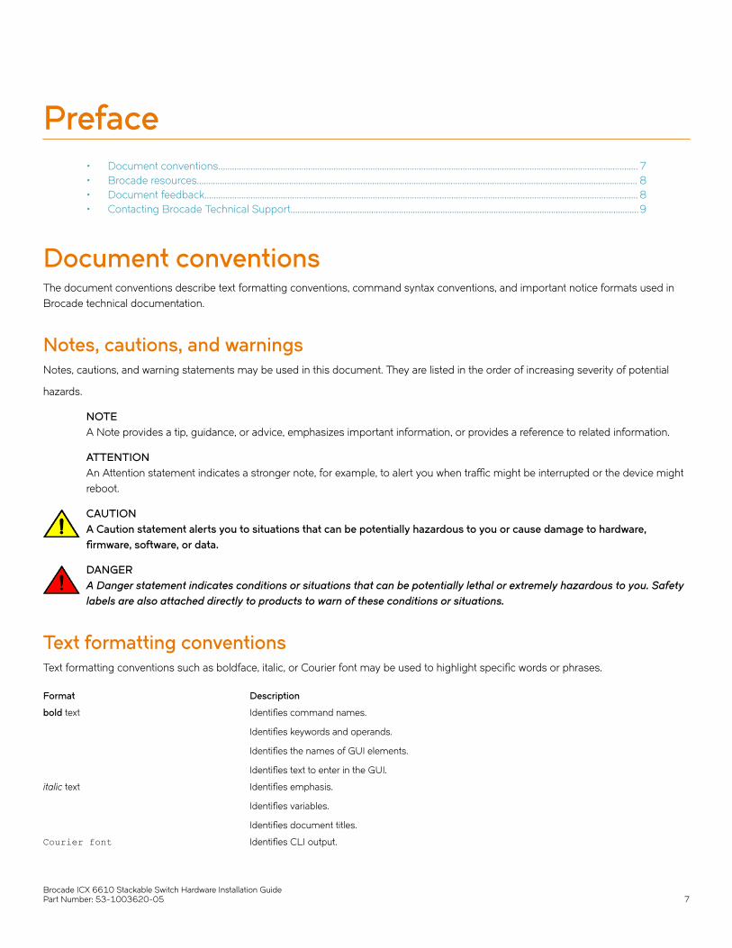
Notes, cautions, and warningsNotes, cautions, and warning statements may be used in this document. They are listed in the order of increasing severity of potential
hazards.
NOTEA Note provides a tip, guidance, or advice, emphasizes important information, or provides a reference to related information.
ATTENTIONAn Attention statement indicates a stronger note, for example, to alert you when traffic might be interrupted or the device mightreboot.
CAUTIONA Caution statement alerts you to situations that can be potentially hazardous to you or cause damage to hardware,firmware, software, or data.
DANGERA Danger statement indicates conditions or situations that can be potentially lethal or extremely hazardous to you. Safetylabels are also attached directly to products to warn of these conditions or situations.
Text formatting conventionsText formatting conventions such as boldface, italic, or Courier font may be used to highlight specific words or phrases.
Format Description
bold text Identifies command names.
Identifies keywords and operands.
Identifies the names of GUI elements.
Identifies text to enter in the GUI.
italic text Identifies emphasis.
Identifies variables.
Identifies document titles.
Courier font Identifies CLI output.
Brocade ICX 6610 Stackable Switch Hardware Installation GuidePart Number: 53-1003620-05 7
Format Description
Identifies command syntax examples.
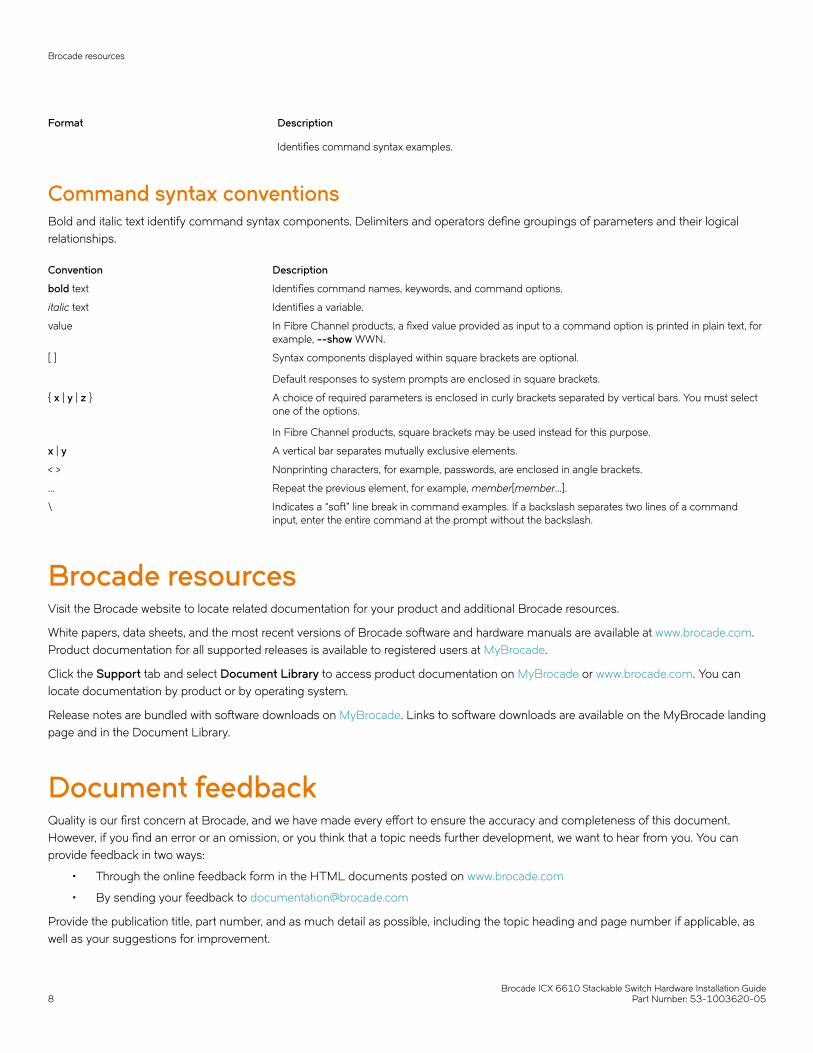
Command syntax conventionsBold and italic text identify command syntax components. Delimiters and operators define groupings of parameters and their logicalrelationships.
Convention Description
bold text Identifies command names, keywords, and command options.
italic text Identifies a variable.
value In Fibre Channel products, a fixed value provided as input to a command option is printed in plain text, forexample, --show WWN.
[ ] Syntax components displayed within square brackets are optional.
Default responses to system prompts are enclosed in square brackets.
{ x | y | z } A choice of required parameters is enclosed in curly brackets separated by vertical bars. You must selectone of the options.
In Fibre Channel products, square brackets may be used instead for this purpose.
x | y A vertical bar separates mutually exclusive elements.
< > Nonprinting characters, for example, passwords, are enclosed in angle brackets.
... Repeat the previous element, for example, member[member...].
\ Indicates a “soft” line break in command examples. If a backslash separates two lines of a commandinput, enter the entire command at the prompt without the backslash.
Brocade resourcesVisit the Brocade website to locate related documentation for your product and additional Brocade resources.
White papers, data sheets, and the most recent versions of Brocade software and hardware manuals are available at www.brocade.com.Product documentation for all supported releases is available to registered users at MyBrocade.
Click the Support tab and select Document Library to access product documentation on MyBrocade or www.brocade.com. You canlocate documentation by product or by operating system.
Release notes are bundled with software downloads on MyBrocade. Links to software downloads are available on the MyBrocade landingpage and in the Document Library.
Document feedbackQuality is our first concern at Brocade, and we have made every effort to ensure the accuracy and completeness of this document.However, if you find an error or an omission, or you think that a topic needs further development, we want to hear from you. You canprovide feedback in two ways:
• Through the online feedback form in the HTML documents posted on www.brocade.com
• By sending your feedback to [email protected]
Provide the publication title, part number, and as much detail as possible, including the topic heading and page number if applicable, aswell as your suggestions for improvement.
Brocade resources
Brocade ICX 6610 Stackable Switch Hardware Installation Guide8 Part Number: 53-1003620-05

Contacting Brocade Technical SupportAs a Brocade customer, you can contact Brocade Technical Support 24x7 online or by telephone. Brocade OEM customers shouldcontact their OEM/solution provider.
Brocade customersFor product support information and the latest information on contacting the Technical Assistance Center, go to www.brocade.com andselect Support.
If you have purchased Brocade product support directly from Brocade, use one of the following methods to contact the BrocadeTechnical Assistance Center 24x7.
Online Telephone
Preferred method of contact for non-urgent issues:
• Case management through the MyBrocade portal.
• Quick Access links to Knowledge Base, Community, DocumentLibrary, Software Downloads and Licensing tools
Required for Sev 1-Critical and Sev 2-High issues:
• Continental US: 1-800-752-8061
• Europe, Middle East, Africa, and Asia Pacific: +800-AT FIBREE(+800 28 34 27 33)
• Toll-free numbers are available in many countries.
• For areas unable to access a toll-free number:+1-408-333-6061
Brocade OEM customersIf you have purchased Brocade product support from a Brocade OEM/solution provider, contact your OEM/solution provider for all ofyour product support needs.
• OEM/solution providers are trained and certified by Brocade to support Brocade® products.
• Brocade provides backline support for issues that cannot be resolved by the OEM/solution provider.
• Brocade Supplemental Support augments your existing OEM support contract, providing direct access to Brocade expertise.For more information, contact Brocade or your OEM.
• For questions regarding service levels and response times, contact your OEM/solution provider.
Contacting Brocade Technical Support
Brocade ICX 6610 Stackable Switch Hardware Installation GuidePart Number: 53-1003620-05 9

Brocade ICX 6610 Stackable Switch Hardware Installation Guide10 Part Number: 53-1003620-05

About This Document• Supported Software..........................................................................................................................................................................................11• What’s new in this document .......................................................................................................................................................................11
Supported SoftwareFor information about the features supported on a hardware platform, refer to the appropriate Features and Standards Support Matrixdocument.
What’s new in this documentThere are no enhancements in this edition.
Brocade ICX 6610 Stackable Switch Hardware Installation GuidePart Number: 53-1003620-05 11

Brocade ICX 6610 Stackable Switch Hardware Installation Guide12 Part Number: 53-1003620-05
ICX 6610 Overview• Hardware features..............................................................................................................................................................................................13• Management interfaces...................................................................................................................................................................................14• Network interfaces for the ICX 6610........................................................................................................................................................15• Specifying a port address...............................................................................................................................................................................18• Port, system, and power status LEDs.......................................................................................................................................................18• Fan trays................................................................................................................................................................................................................ 21• Power supplies....................................................................................................................................................................................................22
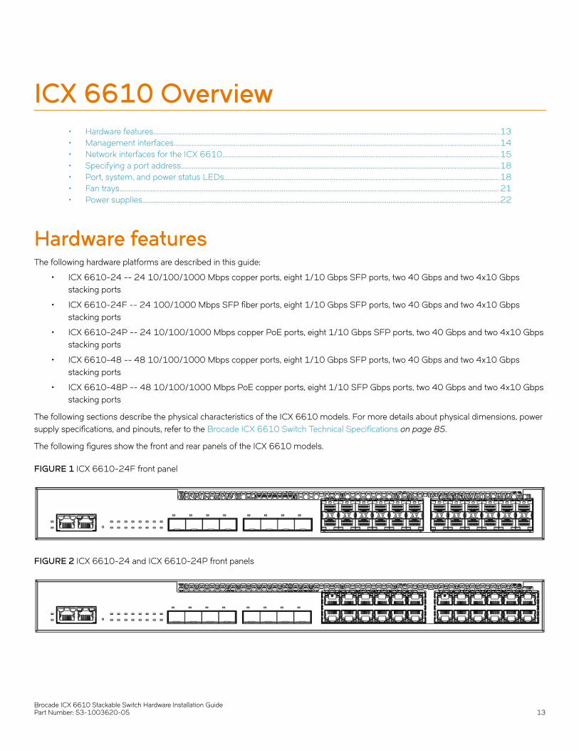
Hardware featuresThe following hardware platforms are described in this guide:
• ICX 6610-24 -- 24 10/100/1000 Mbps copper ports, eight 1/10 Gbps SFP ports, two 40 Gbps and two 4x10 Gbpsstacking ports
• ICX 6610-24F -- 24 100/1000 Mbps SFP fiber ports, eight 1/10 Gbps SFP ports, two 40 Gbps and two 4x10 Gbpsstacking ports
• ICX 6610-24P -- 24 10/100/1000 Mbps copper PoE ports, eight 1/10 Gbps SFP ports, two 40 Gbps and two 4x10 Gbpsstacking ports
• ICX 6610-48 -- 48 10/100/1000 Mbps copper ports, eight 1/10 Gbps SFP ports, two 40 Gbps and two 4x10 Gbpsstacking ports
• ICX 6610-48P -- 48 10/100/1000 Mbps PoE copper ports, eight 1/10 SFP Gbps ports, two 40 Gbps and two 4x10 Gbpsstacking ports
The following sections describe the physical characteristics of the ICX 6610 models. For more details about physical dimensions, powersupply specifications, and pinouts, refer to the Brocade ICX 6610 Switch Technical Specifications on page 85.
The following figures show the front and rear panels of the ICX 6610 models.
FIGURE 1 ICX 6610-24F front panel
FIGURE 2 ICX 6610-24 and ICX 6610-24P front panels
Brocade ICX 6610 Stackable Switch Hardware Installation GuidePart Number: 53-1003620-05 13

FIGURE 3 ICX 6610-24P rear panel
FIGURE 4 ICX 6610-48P rear panel with DC power supply
FIGURE 5 ICX 6610-48 and ICX 6610-48P front panels
FIGURE 6 ICX 6610-48P rear panel
FIGURE 7 ICX 6610-24, ICX 6610-24F, and ICX 6610-48, rear panels
Management interfacesEach ICX 6610 includes the following management interfaces:
• Console management interface (RJ-45 serial port)
• Out-of-band management Interface (RJ-45 port)
• Reset button
These RJ-45 management ports are located together on the left side of the front panel on 24-port models, and in the middle of the rearpanel on 48P-port models.
Management interfaces
Brocade ICX 6610 Stackable Switch Hardware Installation Guide14 Part Number: 53-1003620-05
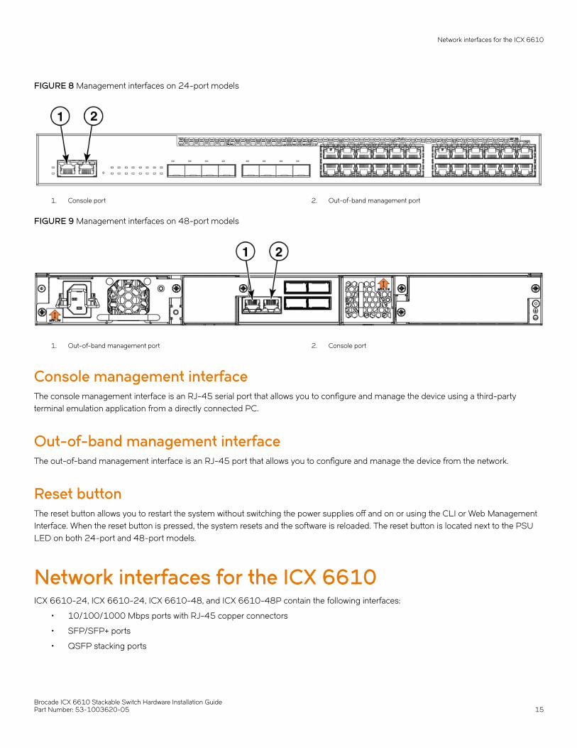
FIGURE 8 Management interfaces on 24-port models
1. Console port 2. Out-of-band management port
FIGURE 9 Management interfaces on 48-port models
1. Out-of-band management port 2. Console port
Console management interfaceThe console management interface is an RJ-45 serial port that allows you to configure and manage the device using a third-partyterminal emulation application from a directly connected PC.
Out-of-band management interfaceThe out-of-band management interface is an RJ-45 port that allows you to configure and manage the device from the network.
Reset buttonThe reset button allows you to restart the system without switching the power supplies off and on or using the CLI or Web ManagementInterface. When the reset button is pressed, the system resets and the software is reloaded. The reset button is located next to the PSULED on both 24-port and 48-port models.
Network interfaces for the ICX 6610ICX 6610-24, ICX 6610-24, ICX 6610-48, and ICX 6610-48P contain the following interfaces:
• 10/100/1000 Mbps ports with RJ-45 copper connectors
• SFP/SFP+ ports
• QSFP stacking ports
Network interfaces for the ICX 6610
Brocade ICX 6610 Stackable Switch Hardware Installation GuidePart Number: 53-1003620-05 15

The ICX 6610-24F contains the following interfaces:
• 100/1000 SFP fiber ports
• SFP/SFP+ ports
• QSFP stacking ports
Slot locationsThere are three slot locations on the ICX 6610: slots 3 and 1 on the front panel and slot 2 on the rear panel.
FIGURE 10 Slot locations on the front panel of the 24-port model of the ICX 6610
1 Slot 3, SFP/SFP+ ports 2 Slot 1, 10/100/1000 Mbps ports
FIGURE 11 Slot locations on the front panel of the 48-port model of the ICX 6610
1 Slot 3, SFP/SFP+ ports 2 Slot 1, 10/100/1000 Mbps ports
The following figure shows slot 2 on the rear panel of the ICX 6610.
FIGURE 12 Slot location on the rear panel of the ICX 6610
Network interfaces for the ICX 6610
Brocade ICX 6610 Stackable Switch Hardware Installation Guide16 Part Number: 53-1003620-05
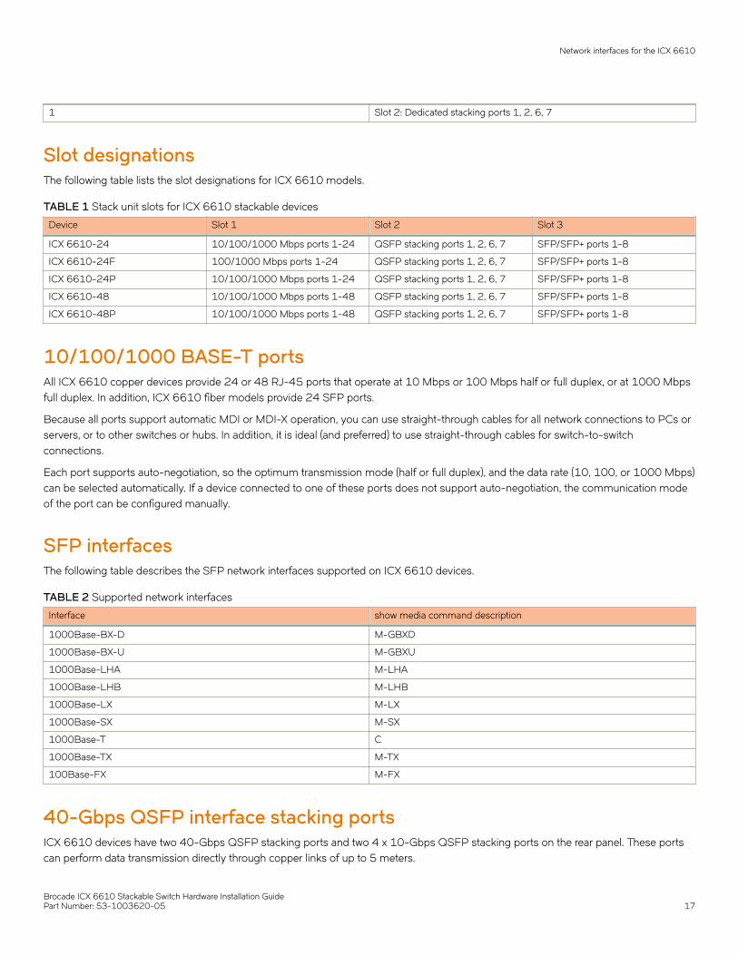
1 Slot 2: Dedicated stacking ports 1, 2, 6, 7
Slot designationsThe following table lists the slot designations for ICX 6610 models.
TABLE 1 Stack unit slots for ICX 6610 stackable devices
Device Slot 1 Slot 2 Slot 3
ICX 6610-24 10/100/1000 Mbps ports 1-24 QSFP stacking ports 1, 2, 6, 7 SFP/SFP+ ports 1-8
ICX 6610-24F 100/1000 Mbps ports 1-24 QSFP stacking ports 1, 2, 6, 7 SFP/SFP+ ports 1-8
ICX 6610-24P 10/100/1000 Mbps ports 1-24 QSFP stacking ports 1, 2, 6, 7 SFP/SFP+ ports 1-8
ICX 6610-48 10/100/1000 Mbps ports 1-48 QSFP stacking ports 1, 2, 6, 7 SFP/SFP+ ports 1-8
ICX 6610-48P 10/100/1000 Mbps ports 1-48 QSFP stacking ports 1, 2, 6, 7 SFP/SFP+ ports 1-8
10/100/1000 BASE-T portsAll ICX 6610 copper devices provide 24 or 48 RJ-45 ports that operate at 10 Mbps or 100 Mbps half or full duplex, or at 1000 Mbpsfull duplex. In addition, ICX 6610 fiber models provide 24 SFP ports.
Because all ports support automatic MDI or MDI-X operation, you can use straight-through cables for all network connections to PCs orservers, or to other switches or hubs. In addition, it is ideal (and preferred) to use straight-through cables for switch-to-switchconnections.
Each port supports auto-negotiation, so the optimum transmission mode (half or full duplex), and the data rate (10, 100, or 1000 Mbps)can be selected automatically. If a device connected to one of these ports does not support auto-negotiation, the communication modeof the port can be configured manually.
SFP interfacesThe following table describes the SFP network interfaces supported on ICX 6610 devices.
TABLE 2 Supported network interfaces
Interface show media command description
1000Base-BX-D M-GBXD
1000Base-BX-U M-GBXU
1000Base-LHA M-LHA
1000Base-LHB M-LHB
1000Base-LX M-LX
1000Base-SX M-SX
1000Base-T C
1000Base-TX M-TX
100Base-FX M-FX
40-Gbps QSFP interface stacking portsICX 6610 devices have two 40-Gbps QSFP stacking ports and two 4 x 10-Gbps QSFP stacking ports on the rear panel. These portscan perform data transmission directly through copper links of up to 5 meters.
Network interfaces for the ICX 6610
Brocade ICX 6610 Stackable Switch Hardware Installation GuidePart Number: 53-1003620-05 17

Specifying a port addressYou can specify a port address for a data port, stacking port, or a management port.
Specifying a data portThe port address format is stack unit/slot/port, where:
• stack unit --Specifies the stack unit ID. Range is from 1 to 8. If the device is not part of a stack, the stack unit ID is 1.
• slot --Specifies the slot number. Can be 1 or 3.
• port --Specifies the port number in the slot. Range is from 1 to 24 (24-port models) or 1 to 48 (48-port models).
This example shows how to specify port 2 in slot 1 of a device that is not part of a stack:
Brocade (config) # interface ethernet 1/1/2
Specifying a stacking portThe port address format is stack unit/slot/port, where:
• stack unit --Specifies the stack unit ID. Range is from 1 to 8.
• slot --Specifies the slot number. Stacking ports are in slot 2.
• port --Specifies the port number in the slot. Dedicated stacking ports are 1, 2, 6, and 7.
This example shows how to specify stacking port 2 in slot 2 of unit 3 in a stack:
Brocade (config) # interface ethernet 3/2/2
Specifying a management portThe management port number is always 1. This example shows how to specify the management port:
Brocade (config) # interface management 1
The Up Link and Down Link LEDs on the front panel indicate operational status. If the Up Link or Down Link LED is on, the port isconnected. If the Up Link or Down Link LED is off, no connection exists, or the link is down.
Port, system, and power status LEDsThe ICX 6610 includes LEDs that indicate the status of device components. This section identifies and describes these LEDs.
Specifying a port address
Brocade ICX 6610 Stackable Switch Hardware Installation Guide18 Part Number: 53-1003620-05

FIGURE 13 Port status LEDs
1 and 2: Port status LEDs
TABLE 3 Port status LEDs
LED Condition Status
Ethernet (1-24/48) On/Flashing Green The port has established a valid link at 1000Mbps. Flashing indicates the port is transmittingand receiving user packets.
On/Flashing YellowThe port has established a valid link at 10 or100 Mbps. Flashing indicates the port istransmitting and receiving user packets.
Off A link is not established with a remote port.
PoE (1-24/48) On The port is providing PoE power to a connecteddevice.
Off The port is not providing PoE power.
SFP/SFP+ (1F-8F) On/Flashing Green The SFP port is operating at 10 Gbps. Flashingindicates the port is transmitting and receivinguser packets.
On/Flashing Yellow The SFP port is operating at 1 Gbps. Flashingindicates the port is transmitting and receivinguser packets.
Off A link is not established with a remote port.
Out-of-band management port (2 LEDs) Off (both LEDs) Offline
On/Flashing (right side) Link-up. Flashing indicates the port istransmitting and receiving user packets.
Green (left side) 1000 Mbps Link-up
Left LED off, right LED on or flashing 10/100 Mbps Link-up. Flashing indicates theport is transmitting and receiving user packets.
Port, system, and power status LEDs
Brocade ICX 6610 Stackable Switch Hardware Installation GuidePart Number: 53-1003620-05 19
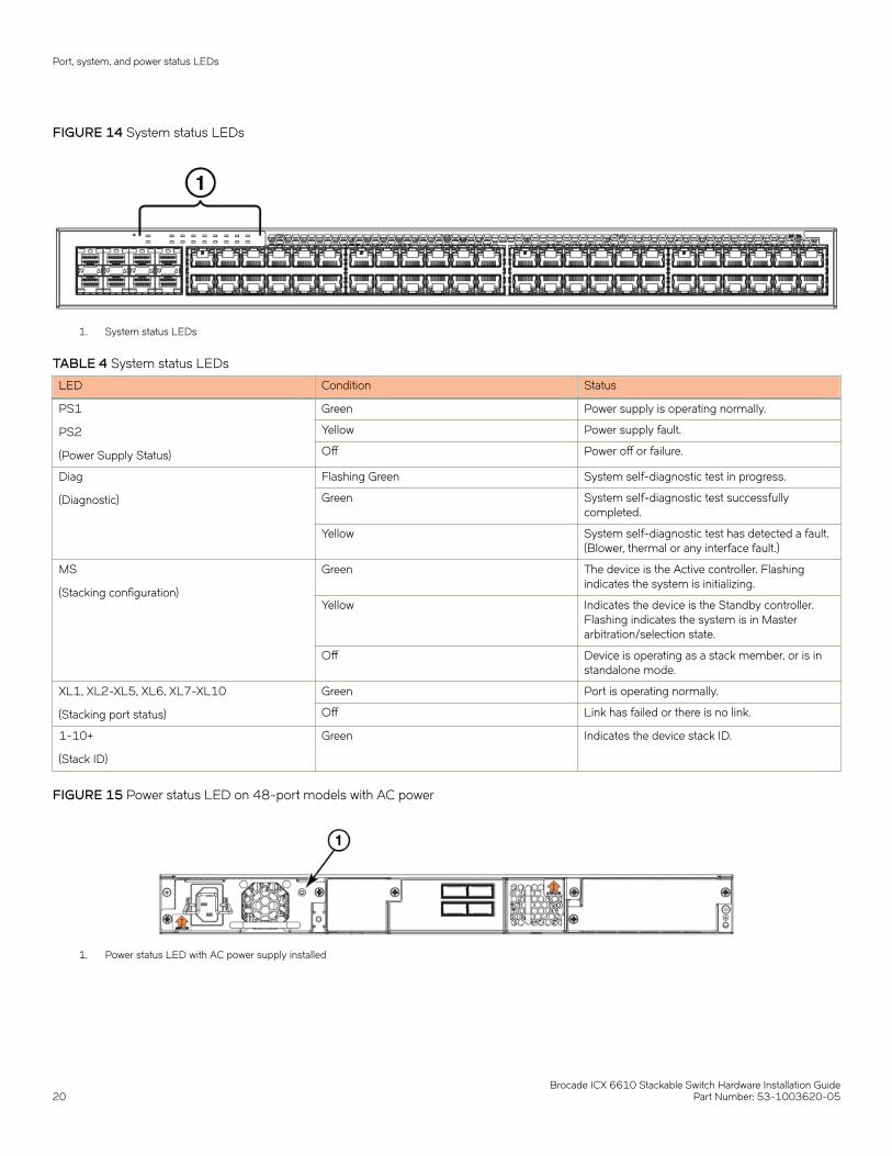
FIGURE 14 System status LEDs
1. System status LEDs
TABLE 4 System status LEDs
LED Condition Status
PS1
PS2
(Power Supply Status)
Green Power supply is operating normally.
Yellow Power supply fault.
Off Power off or failure.
Diag
(Diagnostic)
Flashing Green System self-diagnostic test in progress.
Green System self-diagnostic test successfullycompleted.
Yellow System self-diagnostic test has detected a fault.(Blower, thermal or any interface fault.)
MS
(Stacking configuration)
Green The device is the Active controller. Flashingindicates the system is initializing.
Yellow Indicates the device is the Standby controller.Flashing indicates the system is in Masterarbitration/selection state.
Off Device is operating as a stack member, or is instandalone mode.
XL1, XL2-XL5, XL6, XL7-XL10
(Stacking port status)
Green Port is operating normally.
Off Link has failed or there is no link.
1-10+
(Stack ID)
Green Indicates the device stack ID.
FIGURE 15 Power status LED on 48-port models with AC power
1. Power status LED with AC power supply installed
Port, system, and power status LEDs
Brocade ICX 6610 Stackable Switch Hardware Installation Guide20 Part Number: 53-1003620-05
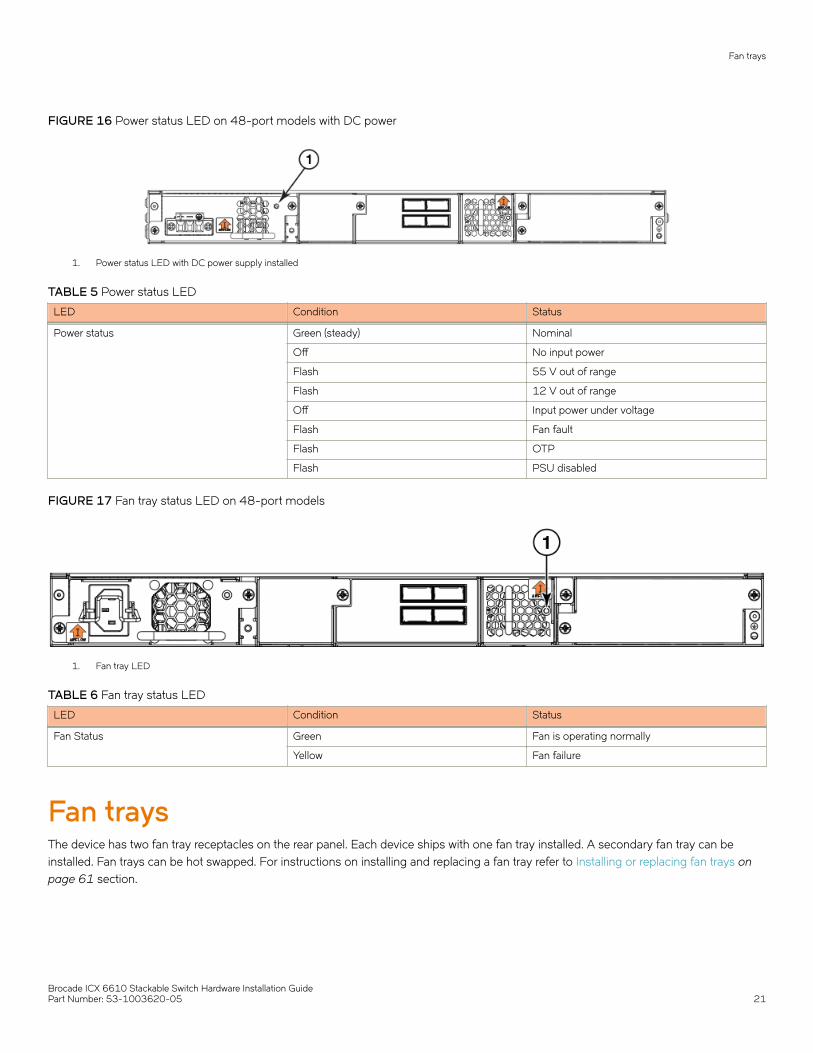
FIGURE 16 Power status LED on 48-port models with DC power
1. Power status LED with DC power supply installed
TABLE 5 Power status LED
LED Condition Status
Power status Green (steady) Nominal
Off No input power
Flash 55 V out of range
Flash 12 V out of range
Off Input power under voltage
Flash Fan fault
Flash OTP
Flash PSU disabled
FIGURE 17 Fan tray status LED on 48-port models
1. Fan tray LED
TABLE 6 Fan tray status LED
LED Condition Status
Fan Status Green Fan is operating normally
Yellow Fan failure
Fan traysThe device has two fan tray receptacles on the rear panel. Each device ships with one fan tray installed. A secondary fan tray can beinstalled. Fan trays can be hot swapped. For instructions on installing and replacing a fan tray refer to Installing or replacing fan trays onpage 61 section.
Fan trays
Brocade ICX 6610 Stackable Switch Hardware Installation GuidePart Number: 53-1003620-05 21
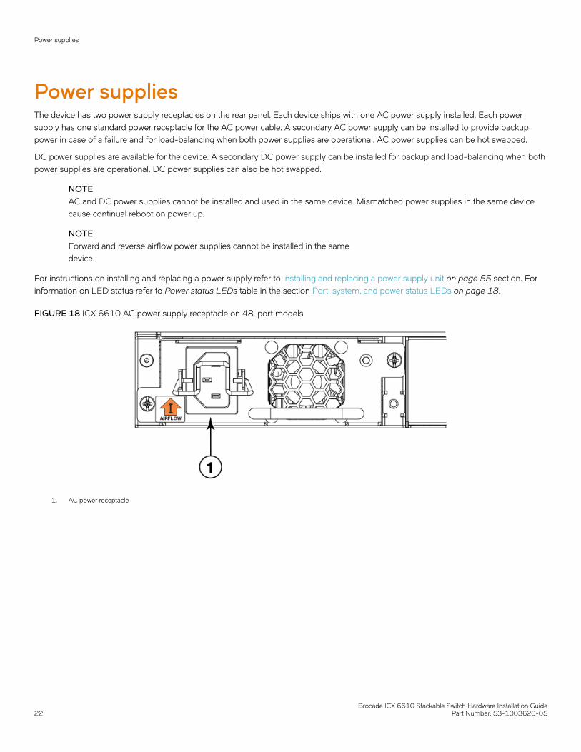
Power suppliesThe device has two power supply receptacles on the rear panel. Each device ships with one AC power supply installed. Each powersupply has one standard power receptacle for the AC power cable. A secondary AC power supply can be installed to provide backuppower in case of a failure and for load-balancing when both power supplies are operational. AC power supplies can be hot swapped.
DC power supplies are available for the device. A secondary DC power supply can be installed for backup and load-balancing when bothpower supplies are operational. DC power supplies can also be hot swapped.
NOTEAC and DC power supplies cannot be installed and used in the same device. Mismatched power supplies in the same devicecause continual reboot on power up.
NOTEForward and reverse airflow power supplies cannot be installed in the samedevice.
For instructions on installing and replacing a power supply refer to Installing and replacing a power supply unit on page 55 section. Forinformation on LED status refer to Power status LEDs table in the section Port, system, and power status LEDs on page 18.
FIGURE 18 ICX 6610 AC power supply receptacle on 48-port models
1. AC power receptacle
Power supplies
Brocade ICX 6610 Stackable Switch Hardware Installation Guide22 Part Number: 53-1003620-05

FIGURE 19 ICX 6610 DC power supply receptacle on 48-port models
1. DC power receptacle
PoE and PoE+ capacity on AC and DC power suppliesSeveral power options are available for the ICX 6610. All power supplies have the same overall form factor but differing power inlets.When a second power supply is installed in the same device for backup or increased capacity, it must be the same type.
Two AC power supplies are available, a 250 Watt unit and a 1000 Watt unit. The 1000 Watt AC power supply can be used for Powerover Ethernet (PoE) applications.
A 510 Watt DC power supply is also available and can be used to supply PoE where DC power is required.
The following table shows capacity per individual power supply and indicates the number of individual devices that can be powered byeach. A second matching power supply can be installed in the device to provide additional PoE power .
TABLE 7 AC and DC power supply capacity
PSU wattage System bus wattage PoE bus wattage Class 4 devices (30 W) perPSU
AC System PSU 250 W 250 W N/A N/A
AC PoE PSU 1000 W 250 W 750 W 25
DC PoE PSU 510 W 250 W 258 W 8
Power supplies
Brocade ICX 6610 Stackable Switch Hardware Installation GuidePart Number: 53-1003620-05 23

Brocade ICX 6610 Stackable Switch Hardware Installation Guide24 Part Number: 53-1003620-05
Installing the ICX 6610 Switch• Unpacking the device.......................................................................................................................................................................................25• Installation tasks................................................................................................................................................................................................. 26• Installation precautions....................................................................................................................................................................................26• Preparing the installation site........................................................................................................................................................................ 28• Installing the device...........................................................................................................................................................................................29• Connecting devices in a traditional stack.................................................................................................................................................40• Connecting devices in a mixed stack........................................................................................................................................................ 44• Attaching a PC or terminal.............................................................................................................................................................................54• Powering on the system................................................................................................................................................................................. 55• Power supplies for the Brocade ICX 6610............................................................................................................................................ 55• Installing or replacing fan trays.....................................................................................................................................................................61
DANGERThe procedures in this manual are for qualified service personnel.
DANGERBefore beginning the installation, see the precautions in “Power precautions.”
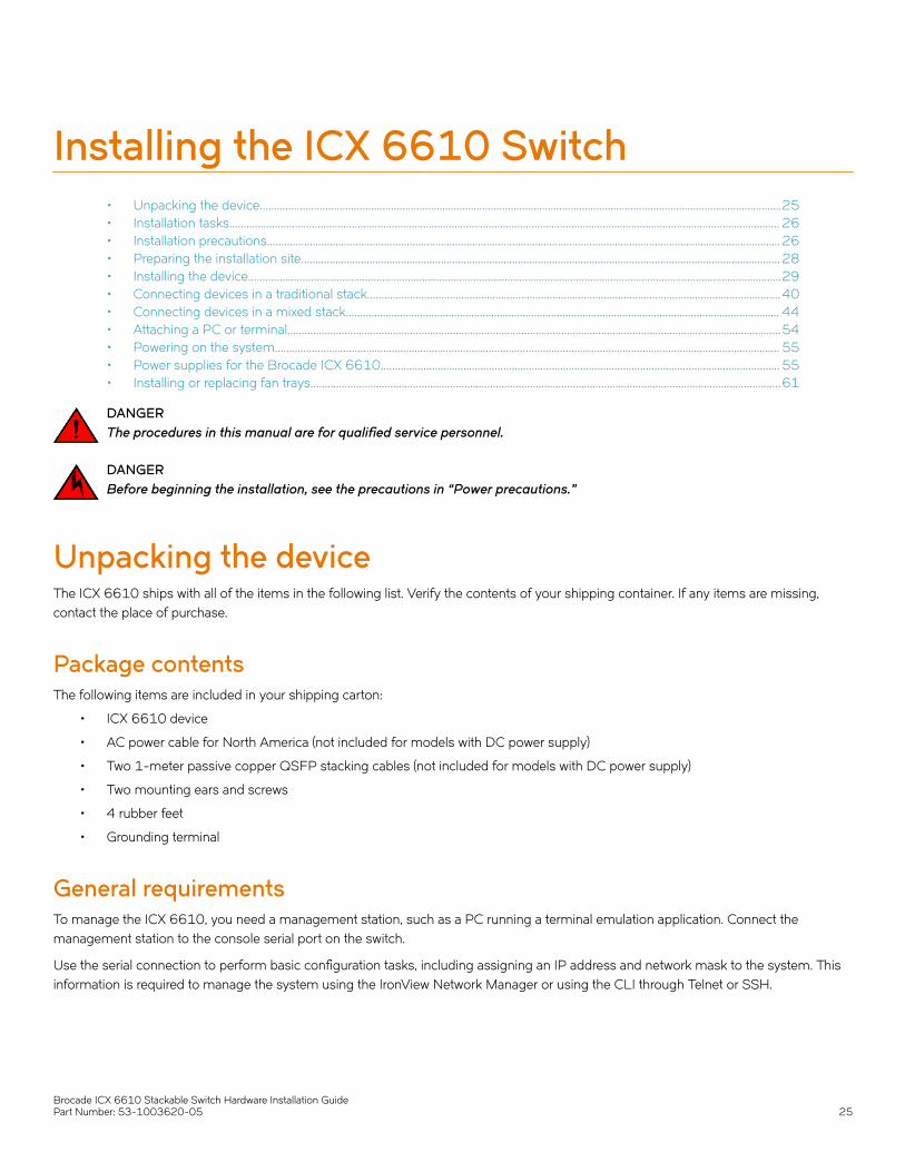
Unpacking the deviceThe ICX 6610 ships with all of the items in the following list. Verify the contents of your shipping container. If any items are missing,contact the place of purchase.
Package contentsThe following items are included in your shipping carton:
• ICX 6610 device
• AC power cable for North America (not included for models with DC power supply)
• Two 1-meter passive copper QSFP stacking cables (not included for models with DC power supply)
• Two mounting ears and screws
• 4 rubber feet
• Grounding terminal
General requirementsTo manage the ICX 6610, you need a management station, such as a PC running a terminal emulation application. Connect themanagement station to the console serial port on the switch.
Use the serial connection to perform basic configuration tasks, including assigning an IP address and network mask to the system. Thisinformation is required to manage the system using the IronView Network Manager or using the CLI through Telnet or SSH.
Brocade ICX 6610 Stackable Switch Hardware Installation GuidePart Number: 53-1003620-05 25
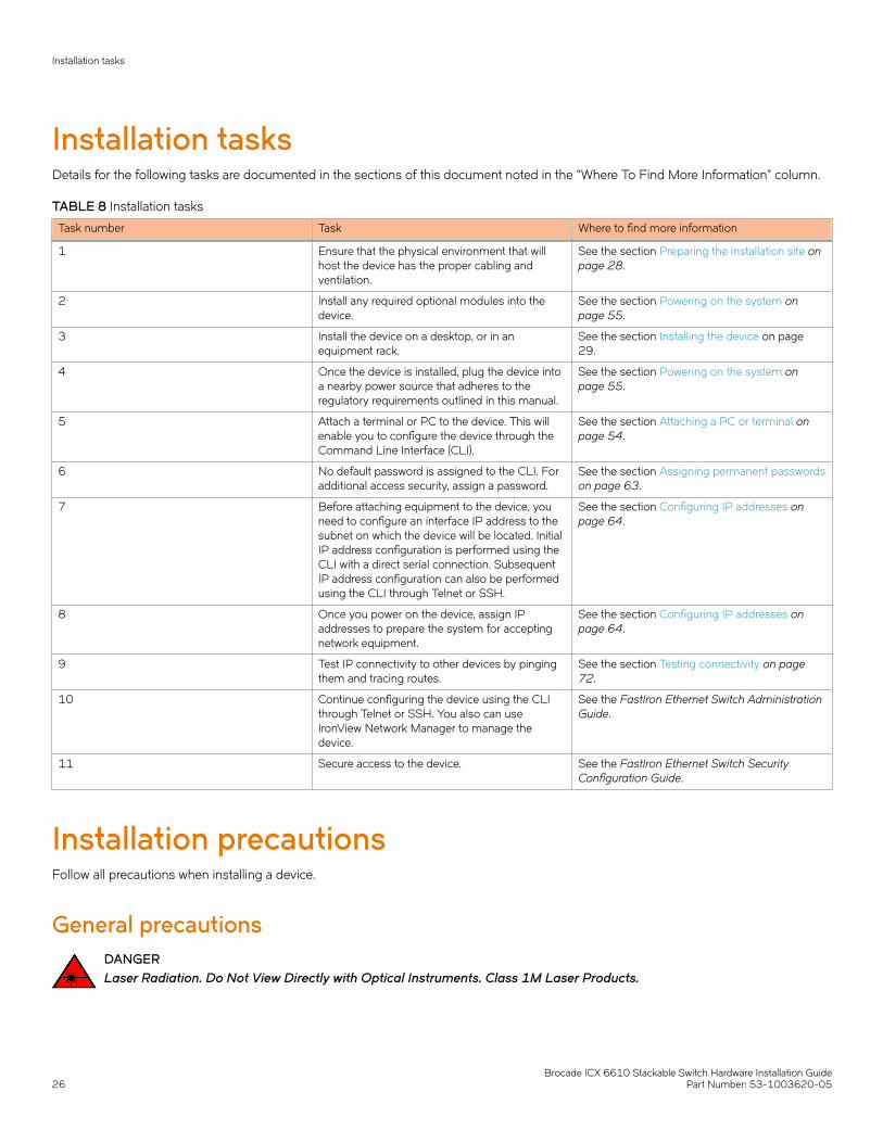
Installation tasksDetails for the following tasks are documented in the sections of this document noted in the “Where To Find More Information” column.
TABLE 8 Installation tasks
Task number Task Where to find more information
1 Ensure that the physical environment that willhost the device has the proper cabling andventilation.
See the section Preparing the installation site onpage 28.
2 Install any required optional modules into thedevice.
See the section Powering on the system onpage 55.
3 Install the device on a desktop, or in anequipment rack.
See the section Installing the device on page29.
4 Once the device is installed, plug the device intoa nearby power source that adheres to theregulatory requirements outlined in this manual.
See the section Powering on the system onpage 55.
5 Attach a terminal or PC to the device. This willenable you to configure the device through theCommand Line Interface (CLI).
See the section Attaching a PC or terminal onpage 54.
6 No default password is assigned to the CLI. Foradditional access security, assign a password.
See the section Assigning permanent passwordson page 63.
7 Before attaching equipment to the device, youneed to configure an interface IP address to thesubnet on which the device will be located. InitialIP address configuration is performed using theCLI with a direct serial connection. SubsequentIP address configuration can also be performedusing the CLI through Telnet or SSH.
See the section Configuring IP addresses onpage 64.
8 Once you power on the device, assign IPaddresses to prepare the system for acceptingnetwork equipment.
See the section Configuring IP addresses onpage 64.
9 Test IP connectivity to other devices by pingingthem and tracing routes.
See the section Testing connectivity on page72.
10 Continue configuring the device using the CLIthrough Telnet or SSH. You also can useIronView Network Manager to manage thedevice.
See the FastIron Ethernet Switch AdministrationGuide.
11 Secure access to the device. See the FastIron Ethernet Switch SecurityConfiguration Guide.
Installation precautionsFollow all precautions when installing a device.
General precautionsDANGERLaser Radiation. Do Not View Directly with Optical Instruments. Class 1M Laser Products.
Installation tasks
Brocade ICX 6610 Stackable Switch Hardware Installation Guide26 Part Number: 53-1003620-05
CAUTIONDo not install the device in an environment where the operating ambient temperature might exceed 45°C (113°F).
CAUTIONMake sure the airflow around the front, sides, and back of the device is notrestricted.
CAUTIONNever leave tools inside the chassis.
DANGERRisk of explosion if battery is replaced by an incorrect type. Dispose of used batteries according to the instructions.
Lifting precautionsDANGERMake sure the rack housing the device is adequately secured to prevent it from becoming unstable or falling over.
DANGERMount the devices you install in a rack as low as possible. Place the heaviest device at the bottom and progressively placelighter devices above.
Power precautionsCAUTIONUse a separate branch circuit for each power cord, which provides redundancy in case one of the circuits fails.
DANGERTo avoid high voltage shock, do not open the device while the power is on.
CAUTIONEnsure that the device does not overload the power circuits, wiring, and over-current protection. To determine thepossibility of overloading the supply circuits, add the ampere (amp) ratings of all devices installed on the same circuit as thedevice. Compare this total with the rating limit for the circuit. The maximum ampere ratings are usually printed on thedevices near the input power connectors.
DANGERRemove both power cords before servicing.
DANGERDisconnect the power cord from all power sources to completely remove power from the device.
CAUTIONBefore plugging a cable into to any port, be sure to discharge the voltage stored on the cable by touching the electricalcontacts to ground surface.
Installation precautions
Brocade ICX 6610 Stackable Switch Hardware Installation GuidePart Number: 53-1003620-05 27

DANGERIf the installation requires a different power cord than the one supplied with the device, make sure you use a power corddisplaying the mark of the safety agency that defines the regulations for power cords in your country. The mark is yourassurance that the power cord can be used safely with the device.
Preparing the installation siteBefore installing the device, plan its location and orientation relative to other devices and equipment.
Cabling infrastructureMake sure that the proper cabling is installed at the site. The following table lists the specifications for the cables used with 10 Gbps, 1Gbps, 100 Mbps, and 10 Mbps ports. For information about supported transceivers, refer to the tables in the Fiber-optic transceivers onpage 70.
NOTECable installation and network configuration affect overall transmission capability. Industry guidelines on cable lengths andrange are provided in the following table. For network-specific recommendations, consult your local Brocade reseller or systemengineer.
TABLE 9 Cable length summary
Cable type Connector type Core diameter(microns)
Modal bandwidth(MHz*km)
Range
10GBase-ER SMF LC 9 µ n/a 40 km
10GBase-LR SMF LC 9 µ n/a 10 km
10GBase-LRM MMF LC 62.5 µ 200 MHz*km 220 m
MMF 50 µ 500 MHz*km 220 m
10GBase-SR MMF LC 50 µ 2000 MHz*km 300 m
10G SFP+ TWNX SFP+ n/a n/a 1, 3, and 5 m
1000Base-BXD SMF LC 9 µ n/a 10 km
1000Base-BXU SMF LC 9 µ n/a 10 km
1000Base-CWDM SMF LC 9 µ n/a 80 km
1000Base-LHA SMF LC 9 µ n/a 80 km
1000Base-LHB SMF LC 9 µ n/a 120 km
1000Base-LX MMF LC 62.5 µ 500 MHz*km 2 - 550 m
MMF 50 µ 400 MHz*km 2 - 550 m
MMF 50 µ 500 MHz*km 2 - 550 m
SMF 9 µ n/a 2 - 10000 m
1000Base-SX MMF LC 62.5 µ 200 MHz*km 0 .5 - 275 m
MMF 50 µ 400 MHz*km 0 .5 - 550 m
MMF 50 µ 500 MHz*km 0 .5 - 550 m
MMF 50 µ 1500 MHz*km 0 .5 - 550 m
MMF 50 µ 2000 MHz*km 0 .5 - 550 m
1000Base-T Copper RJ-45 n/a n/a 100 m
100Base-FX MMF LC 62.5 µ 500 MHz*km 2 km
Preparing the installation site
Brocade ICX 6610 Stackable Switch Hardware Installation Guide28 Part Number: 53-1003620-05
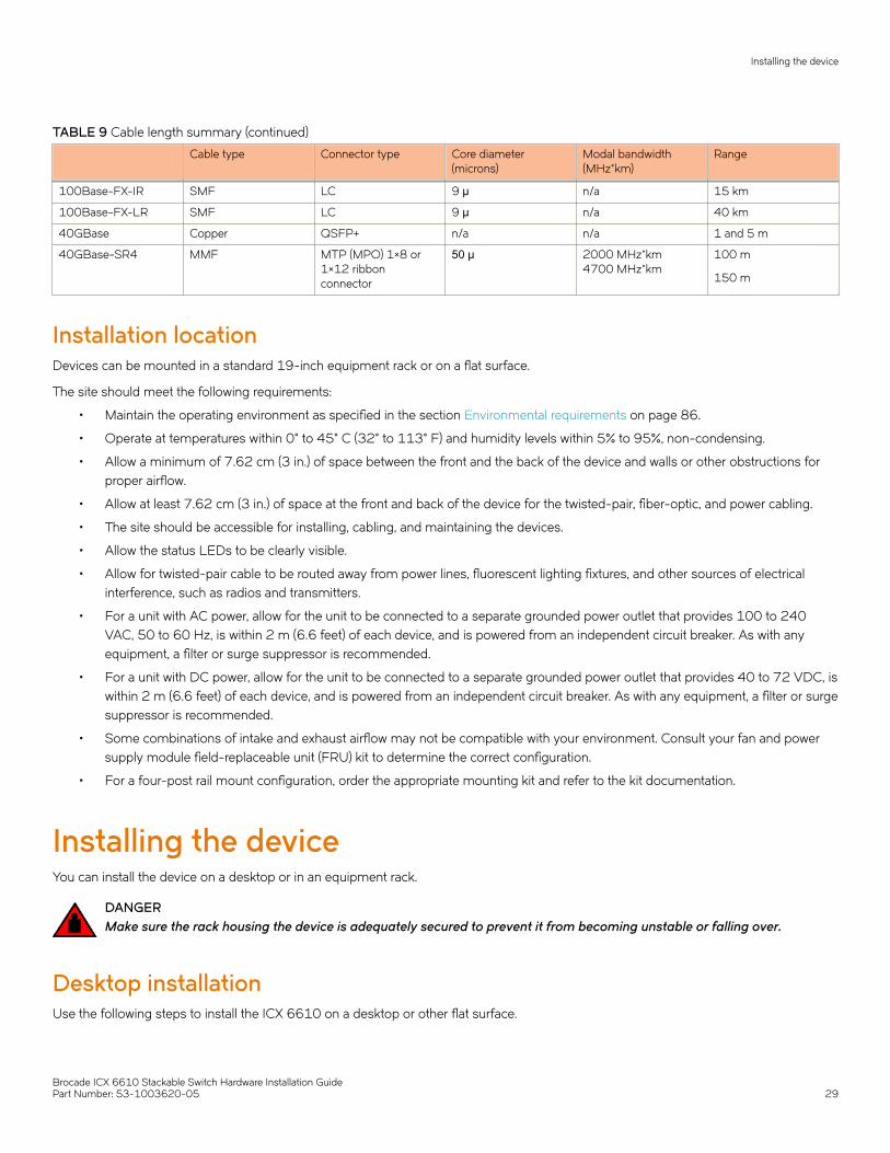
TABLE 9 Cable length summary (continued)
Cable type Connector type Core diameter(microns)
Modal bandwidth(MHz*km)
Range
100Base-FX-IR SMF LC 9 µ n/a 15 km
100Base-FX-LR SMF LC 9 µ n/a 40 km
40GBase Copper QSFP+ n/a n/a 1 and 5 m
40GBase-SR4 MMF MTP (MPO) 1×8 or1×12 ribbonconnector
50 μ 2000 MHz*km4700 MHz*km
100 m
150 m
Installation locationDevices can be mounted in a standard 19-inch equipment rack or on a flat surface.
The site should meet the following requirements:
• Maintain the operating environment as specified in the section Environmental requirements on page 86.
• Operate at temperatures within 0° to 45° C (32° to 113° F) and humidity levels within 5% to 95%, non-condensing.
• Allow a minimum of 7.62 cm (3 in.) of space between the front and the back of the device and walls or other obstructions forproper airflow.
• Allow at least 7.62 cm (3 in.) of space at the front and back of the device for the twisted-pair, fiber-optic, and power cabling.
• The site should be accessible for installing, cabling, and maintaining the devices.
• Allow the status LEDs to be clearly visible.
• Allow for twisted-pair cable to be routed away from power lines, fluorescent lighting fixtures, and other sources of electricalinterference, such as radios and transmitters.
• For a unit with AC power, allow for the unit to be connected to a separate grounded power outlet that provides 100 to 240VAC, 50 to 60 Hz, is within 2 m (6.6 feet) of each device, and is powered from an independent circuit breaker. As with anyequipment, a filter or surge suppressor is recommended.
• For a unit with DC power, allow for the unit to be connected to a separate grounded power outlet that provides 40 to 72 VDC, iswithin 2 m (6.6 feet) of each device, and is powered from an independent circuit breaker. As with any equipment, a filter or surgesuppressor is recommended.
• Some combinations of intake and exhaust airflow may not be compatible with your environment. Consult your fan and powersupply module field-replaceable unit (FRU) kit to determine the correct configuration.
• For a four-post rail mount configuration, order the appropriate mounting kit and refer to the kit documentation.
Installing the deviceYou can install the device on a desktop or in an equipment rack.
DANGERMake sure the rack housing the device is adequately secured to prevent it from becoming unstable or falling over.
Desktop installationUse the following steps to install the ICX 6610 on a desktop or other flat surface.
Installing the device
Brocade ICX 6610 Stackable Switch Hardware Installation GuidePart Number: 53-1003620-05 29

FIGURE 20 Attaching the adhesive feet
1. Attach the four adhesive feet to the bottom of the first switch. If installing multiple switches, attach the adhesive feet to each one.Place each device squarely on top of the one below.
2. Set the device on a flat desktop, table, or shelf near an AC or a DC power source, whichever is appropriate for your installation.Make sure that adequate ventilation is provided for the system. A 3 inch clearance is recommended on each side.
3. If installing a single switch only, refer to the section Powering on the system on page 55.
Rack mount installationNOTEYou will need a Phillips screwdriver for installation.
Before mounting the switch in a rack, pay particular attention to the following factors:
• Temperature: Because the temperature within a rack assembly may be higher than the ambient room temperature, check thatthe rack-environment temperature is within the specified operating temperature range.
• Mechanical loading: Do not place any equipment on top of a rack-mounted unit.
• Circuit overloading: Be sure that the supply circuit to the rack assembly is not overloaded.
• Grounding: Rack-mounted equipment should be properly grounded. Be sure to check supply connections in addition to directconnections to the mains.
Installing the device
Brocade ICX 6610 Stackable Switch Hardware Installation Guide30 Part Number: 53-1003620-05

Two-post rack mount installationNOTEAll ICX 6610 devices are shipped with a two-post rack mount kit to mount the switch into two-post Telco style racks only. If anICX 6610 is to be installed into a standard four-post rack, please make sure that the correct rack mount kit is purchased.
Use the following procedure when installing the ICX 6610 in a two-post rack. For four-post racks, follow the procedures in the section Four-post rack mount installation on page 36.
Remove the rack mount kit from the shipping carton. The kit contains the following:
• Two L-shaped mounting brackets.
• Sixteen 8-32 x 3/8 in., panhead Phillips screws with patchlocks.
• Four 10-32 x 5/8 in., panhead Phillips screws
• Eight 10-32 retainer nuts (for square-hole rack rails)
• Eight 10-32 retainer nuts (for round-hole rack rails)
Installing the device
Brocade ICX 6610 Stackable Switch Hardware Installation GuidePart Number: 53-1003620-05 31
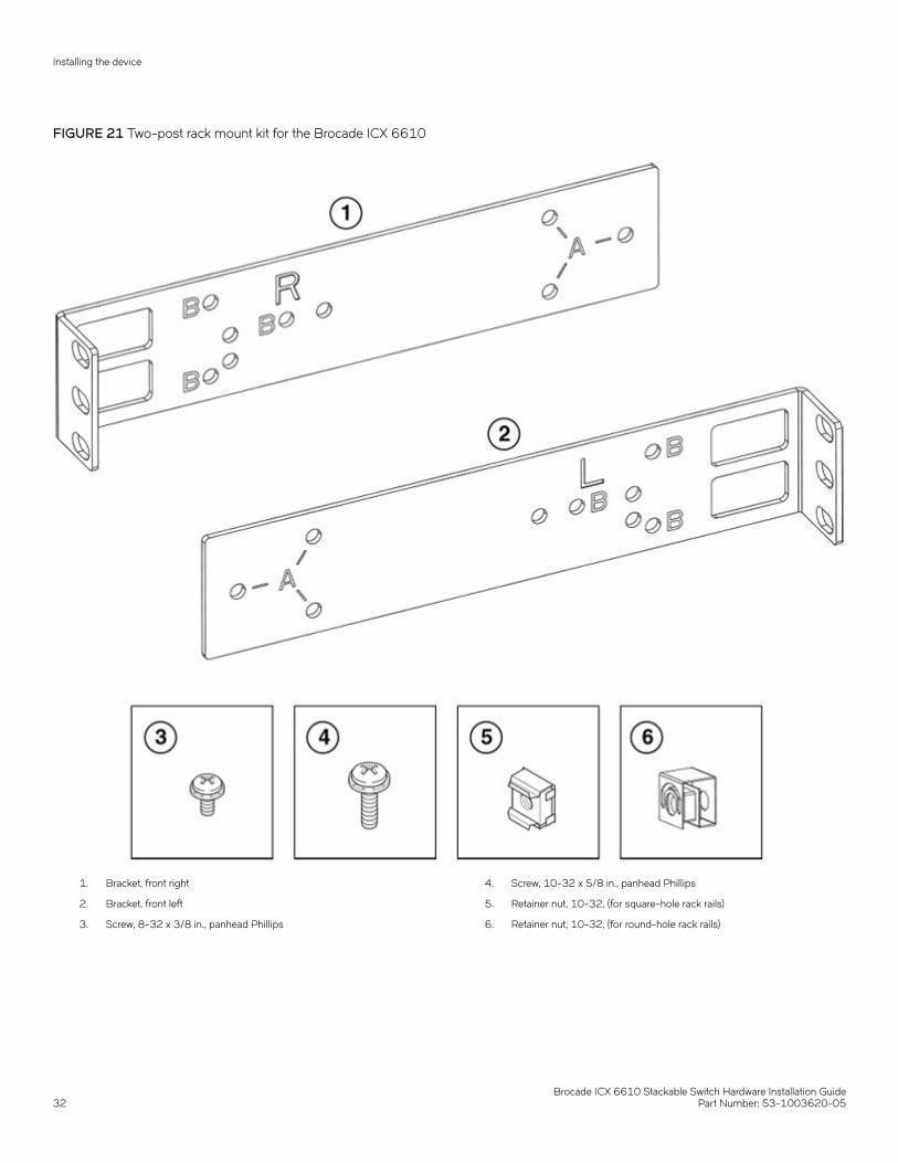
FIGURE 21 Two-post rack mount kit for the Brocade ICX 6610
1. Bracket, front right
2. Bracket, front left
3. Screw, 8-32 x 3/8 in., panhead Phillips
4. Screw, 10-32 x 5/8 in., panhead Phillips
5. Retainer nut, 10-32, (for square-hole rack rails)
6. Retainer nut, 10-32, (for round-hole rack rails)
Installing the device
Brocade ICX 6610 Stackable Switch Hardware Installation Guide32 Part Number: 53-1003620-05
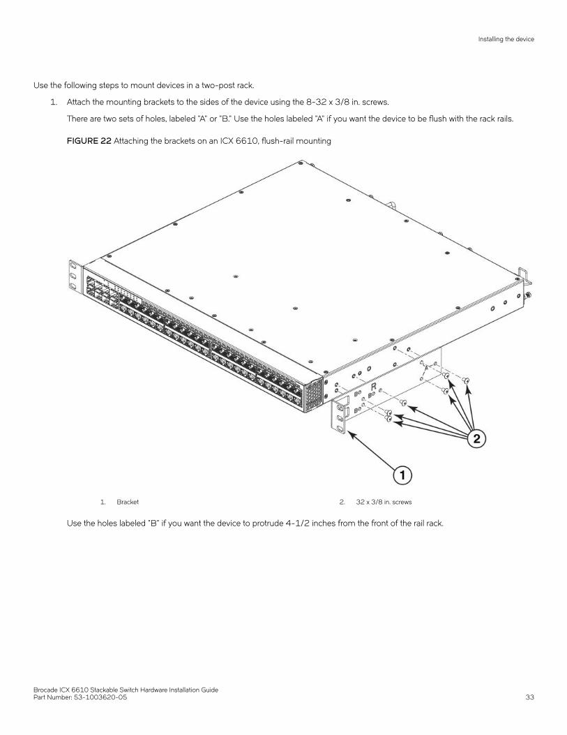
Use the following steps to mount devices in a two-post rack.
1. Attach the mounting brackets to the sides of the device using the 8-32 x 3/8 in. screws.
There are two sets of holes, labeled "A" or "B." Use the holes labeled "A" if you want the device to be flush with the rack rails.
FIGURE 22 Attaching the brackets on an ICX 6610, flush-rail mounting
1. Bracket 2. 32 x 3/8 in. screws
Use the holes labeled "B" if you want the device to protrude 4-1/2 inches from the front of the rail rack.
Installing the device
Brocade ICX 6610 Stackable Switch Hardware Installation GuidePart Number: 53-1003620-05 33
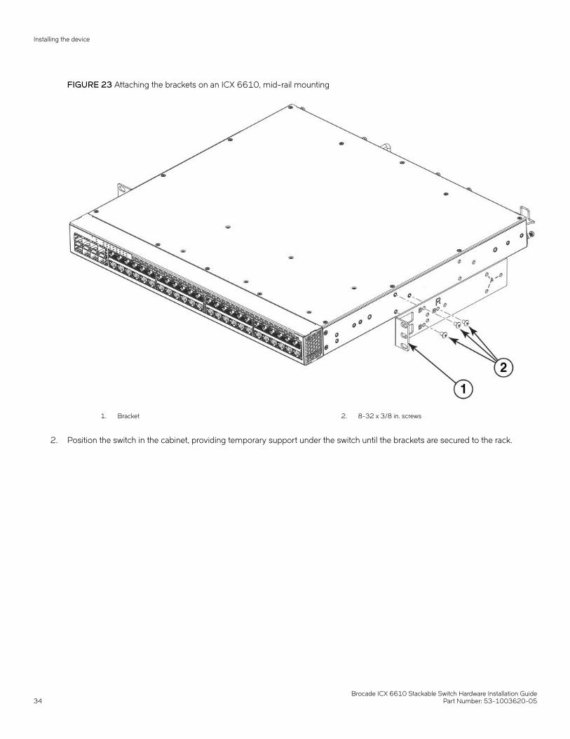
FIGURE 23 Attaching the brackets on an ICX 6610, mid-rail mounting
1. Bracket 2. 8-32 x 3/8 in. screws
2. Position the switch in the cabinet, providing temporary support under the switch until the brackets are secured to the rack.
Installing the device
Brocade ICX 6610 Stackable Switch Hardware Installation Guide34 Part Number: 53-1003620-05
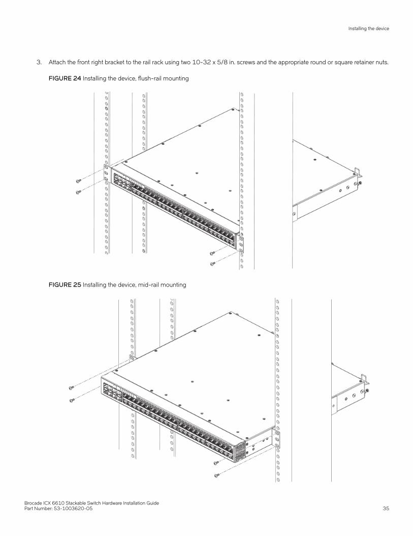
3. Attach the front right bracket to the rail rack using two 10-32 x 5/8 in. screws and the appropriate round or square retainer nuts.
FIGURE 24 Installing the device, flush-rail mounting
FIGURE 25 Installing the device, mid-rail mounting
Installing the device
Brocade ICX 6610 Stackable Switch Hardware Installation GuidePart Number: 53-1003620-05 35

4. Repeat Step 1 to Step 3 to attach the left front bracket to the left front rack rail and tighten all 10-32 x 5/8 in. screws to atorque of 25 in-lb (29 cm-kg).
Four-post rack mount installationKits for four-post rack mounting are not included in the shipping carton and must be ordered separately.
NOTEUse the following procedure when installing the ICX 6610 in a four-post rack cabinet. For two-post cabinets, follow theprocedures in the section Two-post rack mount installation on page 31.
Remove the rack mount kit from the shipping carton. The kit contains the following:
• Two mounting brackets
• Two pairs of extension brackets. Use the shorter pair for racks that are up to 27 inches deep. Use the longer pair for racks up to32 inches deep.
• Thirty-two 8-32 x 3/8 in., panhead Phillips screws with patchlocks
• Eight 10-32 x 5/8 in., panhead Phillips screws
• Eight 32-10 retainer nuts (for square-hole rack rails)
• Eight 32-10 retainer nuts (for round-hole rack rails)
Installing the device
Brocade ICX 6610 Stackable Switch Hardware Installation Guide36 Part Number: 53-1003620-05
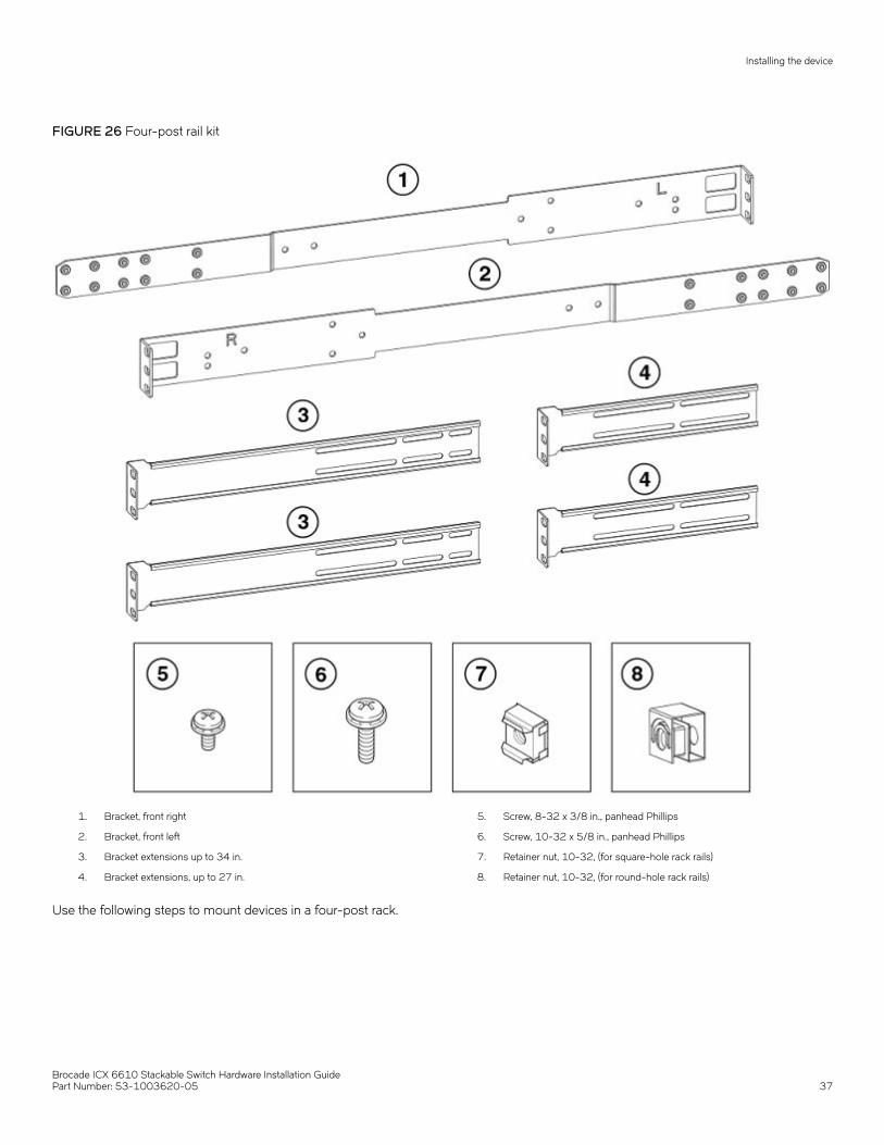
FIGURE 26 Four-post rail kit
1. Bracket, front right
2. Bracket, front left
3. Bracket extensions up to 34 in.
4. Bracket extensions, up to 27 in.
5. Screw, 8-32 x 3/8 in., panhead Phillips
6. Screw, 10-32 x 5/8 in., panhead Phillips
7. Retainer nut, 10-32, (for square-hole rack rails)
8. Retainer nut, 10-32, (for round-hole rack rails)
Use the following steps to mount devices in a four-post rack.
Installing the device
Brocade ICX 6610 Stackable Switch Hardware Installation GuidePart Number: 53-1003620-05 37

NOTEDo not use the hardware supplied in a two-post rack mounting kit to mount an ICX 6610 in a four-post rack. Mounting thedevice in a four-post rack requires additional hardware to prevent possible flexing and distortion of the four-post rack when adevice is not properly installed.
1. Attach the mounting brackets to the sides of the device using the 8-32 x 3/8 in. screws
FIGURE 27 Attaching four-post brackets
1. Bracket 2. 8-32 x 3/8 in. screws
Installing the device
Brocade ICX 6610 Stackable Switch Hardware Installation Guide38 Part Number: 53-1003620-05
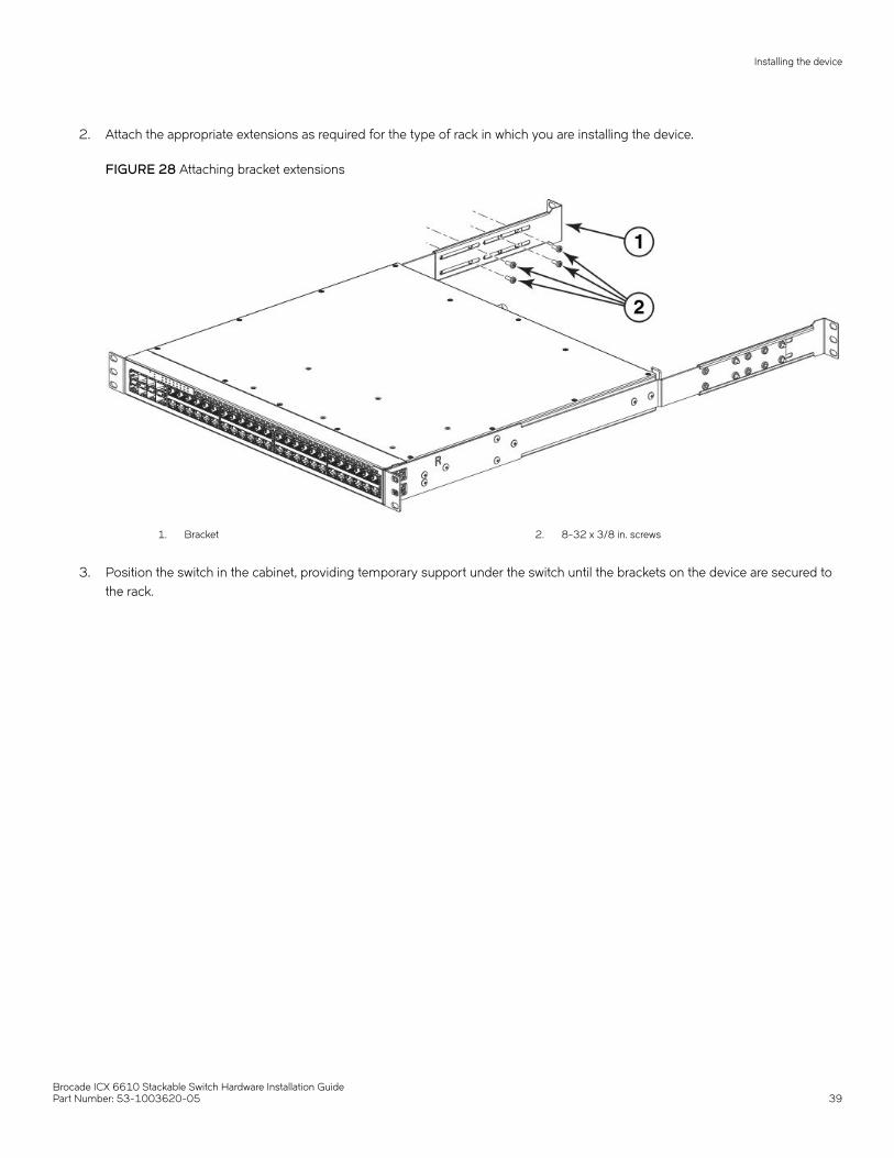
2. Attach the appropriate extensions as required for the type of rack in which you are installing the device.
FIGURE 28 Attaching bracket extensions
1. Bracket 2. 8-32 x 3/8 in. screws
3. Position the switch in the cabinet, providing temporary support under the switch until the brackets on the device are secured tothe rack.
Installing the device
Brocade ICX 6610 Stackable Switch Hardware Installation GuidePart Number: 53-1003620-05 39
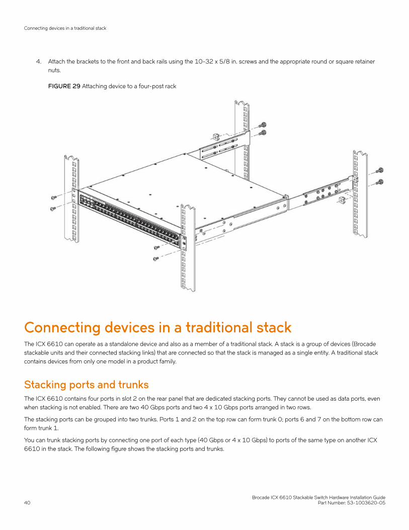
4. Attach the brackets to the front and back rails using the 10-32 x 5/8 in. screws and the appropriate round or square retainernuts.
FIGURE 29 Attaching device to a four-post rack
Connecting devices in a traditional stackThe ICX 6610 can operate as a standalone device and also as a member of a traditional stack. A stack is a group of devices (Brocadestackable units and their connected stacking links) that are connected so that the stack is managed as a single entity. A traditional stackcontains devices from only one model in a product family.
Stacking ports and trunksThe ICX 6610 contains four ports in slot 2 on the rear panel that are dedicated stacking ports. They cannot be used as data ports, evenwhen stacking is not enabled. There are two 40 Gbps ports and two 4 x 10 Gbps ports arranged in two rows.
The stacking ports can be grouped into two trunks. Ports 1 and 2 on the top row can form trunk 0; ports 6 and 7 on the bottom row canform trunk 1.
You can trunk stacking ports by connecting one port of each type (40 Gbps or 4 x 10 Gbps) to ports of the same type on another ICX6610 in the stack. The following figure shows the stacking ports and trunks.
Connecting devices in a traditional stack
Brocade ICX 6610 Stackable Switch Hardware Installation Guide40 Part Number: 53-1003620-05

FIGURE 30 Dedicated stacking ports and trunks in slot 2 on an ICX 6610
1. 1-Port 1, 40 Gbps
2. 2-Trunk 0
3. 3-Port 2, 4 x 10 Gbps
4. 4- Port 6, 40 Gbps
5. 5-Trunk 1
6. 6- Port 7, 4 x 10 Gbps
Trunking requirements• You can connect one or both ports in a trunk. Connecting both ports in a trunk increases stacking bandwidth and provides
resiliency.
• You must connect each port type (40 Gbps or 4x10 Gbps) to the same type of port on another device as shown in thefollowing table.
• If you connect both ports in a trunk, both ports must connect to both ports of one trunk on another device.
TABLE 10 Port connections for trunking between ICX 6610 devices
Valid port connections Invalid port connections
Device 1 Device 2 Device 1 Device 2
Port 1 to Port 1 Port 1 to Port 2
Port 1 to Port 6 Port 1 to Port 7
Port 2 to Port 2 Port 2 to Port 1
Port 2 to Port 7 Port 2 to Port 6
Stacking configuration requirementsBefore configuring the traditional stack using the CLI, physically connect the devices using stacking cables. For information aboutconfiguring a stack, refer to the FastIron Ethernet Switch Stacking Configuration Guide.
Stacking cablesUse 1 meter passive copper QSFP stacking cables or SFP+ fiber-optic cables to connect ICX 6610 devices in a traditional stack. The40G-QSFP-SR4 optical transceiver is also supported.
Stack sizeA traditional stack can contain a maximum of eight ICX 6610 devices.
Connecting devices in a traditional stack
Brocade ICX 6610 Stackable Switch Hardware Installation GuidePart Number: 53-1003620-05 41
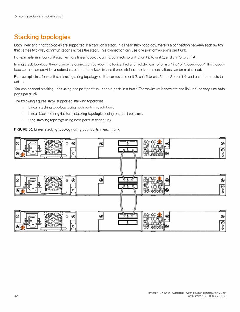
Stacking topologiesBoth linear and ring topologies are supported in a traditional stack. In a linear stack topology, there is a connection between each switchthat carries two-way communications across the stack. This connection can use one port or two ports per trunk.
For example, in a four-unit stack using a linear topology, unit 1 connects to unit 2, unit 2 to unit 3, and unit 3 to unit 4.
In ring stack topology, there is an extra connection between the logical first and last devices to form a "ring" or "closed-loop." The closed-loop connection provides a redundant path for the stack link, so if one link fails, stack communications can be maintained.
For example, in a four-unit stack using a ring topology, unit 1 connects to unit 2, unit 2 to unit 3, unit 3 to unit 4, and unit 4 connects tounit 1.
You can connect stacking units using one port per trunk or both ports in a trunk. For maximum bandwidth and link redundancy, use bothports per trunk.
The following figures show supported stacking topologies:
• Linear stacking topology using both ports in each trunk
• Linear (top) and ring (bottom) stacking topologies using one port per trunk
• Ring stacking topology using both ports in each trunk
FIGURE 31 Linear stacking topology using both ports in each trunk
Connecting devices in a traditional stack
Brocade ICX 6610 Stackable Switch Hardware Installation Guide42 Part Number: 53-1003620-05
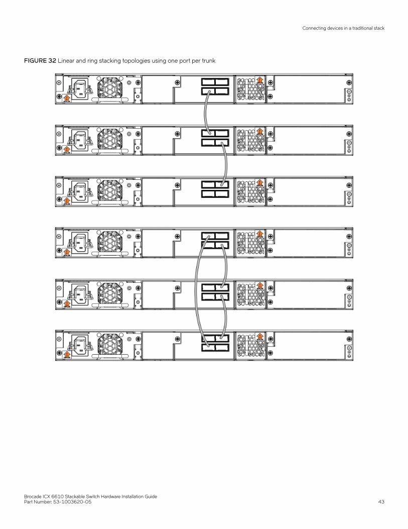
FIGURE 32 Linear and ring stacking topologies using one port per trunk
Connecting devices in a traditional stack
Brocade ICX 6610 Stackable Switch Hardware Installation GuidePart Number: 53-1003620-05 43
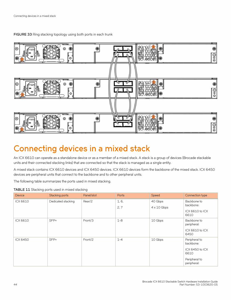
FIGURE 33 Ring stacking topology using both ports in each trunk
Connecting devices in a mixed stackAn ICX 6610 can operate as a standalone device or as a member of a mixed stack. A stack is a group of devices (Brocade stackableunits and their connected stacking links) that are connected so that the stack is managed as a single entity.
A mixed stack contains ICX 6610 devices and ICX 6450 devices. ICX 6610 devices form the backbone of the mixed stack. ICX 6450devices are peripheral units that connect to the backbone and to other peripheral units.
The following table summarizes the ports used in mixed stacking.
TABLE 11 Stacking ports used in mixed stacking
Device Stacking ports Panel/slot Ports Speed Connection type
ICX 6610 Dedicated stacking Rear/2 1, 6,
2, 7
40 Gbps
4 x 10 Gbps
Backbone tobackbone:
ICX 6610 to ICX6610
ICX 6610 SFP+ Front/3 1-8 10 Gbps Backbone toperipheral:
ICX 6610 to ICX6450
ICX 6450 SFP+ Front/2 1-4 10 Gbps Peripheral tobackbone:
ICX 6450 to ICX6610
Peripheral toperipheral:
Connecting devices in a mixed stack
Brocade ICX 6610 Stackable Switch Hardware Installation Guide44 Part Number: 53-1003620-05
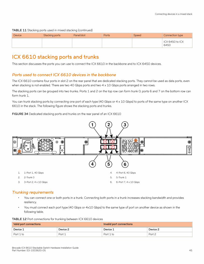
TABLE 11 Stacking ports used in mixed stacking (continued)
Device Stacking ports Panel/slot Ports Speed Connection type
ICX 6450 to ICX6450
ICX 6610 stacking ports and trunksThis section discusses the ports you can use to connect the ICX 6610 in the backbone and to ICX 6450 devices.
Ports used to connect ICX 6610 devices in the backboneThe ICX 6610 contains four ports in slot 2 on the rear panel that are dedicated stacking ports. They cannot be used as data ports, evenwhen stacking is not enabled. There are two 40 Gbps ports and two 4 x 10 Gbps ports arranged in two rows.
The stacking ports can be grouped into two trunks. Ports 1 and 2 on the top row can form trunk 0; ports 6 and 7 on the bottom row canform trunk 1.
You can trunk stacking ports by connecting one port of each type (40 Gbps or 4 x 10 Gbps) to ports of the same type on another ICX6610 in the stack. The following figure shows the stacking ports and trunks.
FIGURE 34 Dedicated stacking ports and trunks on the rear panel of an ICX 6610
1. 1-Port 1, 40 Gbps
2. 2-Trunk 0
3. 3-Port 2, 4 x 10 Gbps
4. 4-Port 6, 40 Gbps
5. 5-Trunk 1
6. 6-Port 7, 4 x 10 Gbps
Trunking requirements• You can connect one or both ports in a trunk. Connecting both ports in a trunk increases stacking bandwidth and provides
resiliency.
• You must connect each port type (40 Gbps or 4x10 Gbps) to the same type of port on another device as shown in thefollowing table.
TABLE 12 Port connections for trunking between ICX 6610 devices
Valid port connections Invalid port connections
Device 1 Device 2 Device 1 Device 2
Port 1 to Port 1 Port 1 to Port 2
Connecting devices in a mixed stack
Brocade ICX 6610 Stackable Switch Hardware Installation GuidePart Number: 53-1003620-05 45
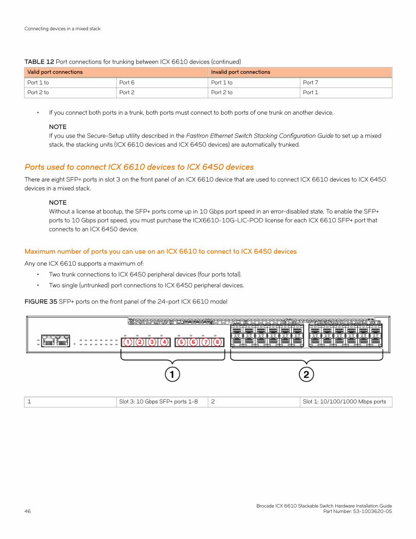
TABLE 12 Port connections for trunking between ICX 6610 devices (continued)
Valid port connections Invalid port connections
Port 1 to Port 6 Port 1 to Port 7
Port 2 to Port 2 Port 2 to Port 1
• If you connect both ports in a trunk, both ports must connect to both ports of one trunk on another device.
NOTEIf you use the Secure-Setup utility described in the FastIron Ethernet Switch Stacking Configuration Guide to set up a mixedstack, the stacking units (ICX 6610 devices and ICX 6450 devices) are automatically trunked.
Ports used to connect ICX 6610 devices to ICX 6450 devicesThere are eight SFP+ ports in slot 3 on the front panel of an ICX 6610 device that are used to connect ICX 6610 devices to ICX 6450devices in a mixed stack.
NOTEWithout a license at bootup, the SFP+ ports come up in 10 Gbps port speed in an error-disabled state. To enable the SFP+ports to 10 Gbps port speed, you must purchase the ICX6610-10G-LIC-POD license for each ICX 6610 SFP+ port thatconnects to an ICX 6450 device.
Maximum number of ports you can use on an ICX 6610 to connect to ICX 6450 devices
Any one ICX 6610 supports a maximum of:
• Two trunk connections to ICX 6450 peripheral devices (four ports total).
• Two single (untrunked) port connections to ICX 6450 peripheral devices.
FIGURE 35 SFP+ ports on the front panel of the 24-port ICX 6610 model
1 Slot 3: 10 Gbps SFP+ ports 1-8 2 Slot 1: 10/100/1000 Mbps ports
Connecting devices in a mixed stack
Brocade ICX 6610 Stackable Switch Hardware Installation Guide46 Part Number: 53-1003620-05

FIGURE 36 SFP+ ports on the front panel of the 48-port ICX 6610 model
1 Slot 3: 10 Gbps SFP+ ports 1-8 2 Slot 1: 10/100/1000 Mbps ports
ICX 6450 stacking ports and trunksThe ICX 6450 contains four SFP+ ports in slot 2 on the front panel that can be used as uplink (data) ports or as stacking ports. Thefollowing figure shows the ports in slot 2. The top row consists of ports 1 and 3, and the bottom row consists of ports 2 and 4.
FIGURE 37 Stacking ports on the front panel of an ICX 6450
1. Console port
2. Slot 2 (SFP and SFP + uplink or stacking ports)
3. Out-of-band management port
4. Slot 1 (10/100/1000 Mbps ports)
Ports 1 and 3 are default stacking ports. Default stacking ports have the capability to accept special stacking packets during a CLI-initiated command sequence of the Secure-Setup utility. If ports 1 and 3 are not used as stacking ports, you can use them as data ports.Configuration is not required to use them as data ports.
All four ports in slot 2 can be used as stacking ports.
The stacking ports can be grouped into two trunks. Ports 1 and 2 can form a trunk. Ports 3 and 4 can form another trunk. By default,ICX 6450 devices are not configured for trunking.
On the ICX 6450, ports 1 and 3 are 10 Gbps ports.
NOTEWithout a license at bootup, ICX 6450 ports 2 and 4 come up in 10 Gbps port speed in an error disabled state. To enableports 2 and 4 to 10 Gbps port speed, you must purchase the ICX6450-2X10G-LIC-POD license.
For more information about enabling ports 2 and 4 to 10 Gbps port speed, refer to the FastIron Ethernet Switch Administration Guide.
Connecting devices in a mixed stack
Brocade ICX 6610 Stackable Switch Hardware Installation GuidePart Number: 53-1003620-05 47

Trunking requirements• You can connect one or both ports in a trunk. Connecting both ports in a trunk increases stacking bandwidth and provides
resiliency.
• If you connect both ports in a trunk, both ports must connect to both ports of one trunk on another device.
• When configuring a trunk, the ports in the same column are always trunked (port 1 to port 2, port 3 to port 4). One or both ofthe two sets of stacking ports can be trunked (or untrunked).
• For ICX 6450 devices, all stacking ports must be configured to 10 Gbps port speed to enable trunking.
NOTEIf you use the Secure-Setup utility described in the FastIron Ethernet Switch Stacking Configuration Guide to set up a mixedstack, the stacking units (ICX 6610 devices and ICX 6450 devices) are automatically trunked.
Stacking configuration requirementsBefore configuring the mixed stack, physically connect the devices using stacking cables.
Secure-Setup utilityTo connect the SFP+ ports on the front of the ICX 6610 to ICX 6450 devices, configure the ports to 10 Gbps using the speedcommand as described in the Secure-Setup utility.
Refer to the FastIron Ethernet Switch Stacking Configuration Guide for a full description of using the Secure-Setup utility to connect theICX 6610 in a mixed stack.
Automatic and manual configuration methodsTo connect an ICX 6610 in the backbone to an ICX 6450 peripheral unit, use the peri-port command or peri-trunk command on theICX 6610.
The ICX 6610 can be configured in a mixed stack manually, automatically, or using the Secure-Setup utility. For information on allconfiguration methods, refer to the FastIron Ethernet Switch Stacking Configuration Guide.
Stacking cablesThe following table shows the cables to connect devices in a mixed stack.
TABLE 13 Cables to connect devices in a mixed stack
To connect this device To this device Use this cable
ICX 6610 ICX 6610 1 meter passive copper QSFP stacking cable
100 meter QSFP fiber-optic cable
ICX 6450 ICX 6450 SFP+ fiber-optic cable
10 Gbps copper stacking cable
ICX 6610 ICX 6450 SFP+ fiber-optic cable
10 Gbps copper stacking cable
Connecting devices in a mixed stack
Brocade ICX 6610 Stackable Switch Hardware Installation Guide48 Part Number: 53-1003620-05

Stack sizeA mixed stack can contain one or two ICX 6610 devices. They form the backbone of the mixed stack. ICX 6450 devices are peripheralunits. There can be one to six ICX 6450 devices in a mixed stack.
Peripheral devices can form one or more substacks. A substack is a topology that is formed by ICX 6450 devices. If ICX 6450 devicesare separated by an ICX 6610 device, the ICX 6450 devices belong to different substacks.
Stacking topologiesTwo basic ring topologies are supported in a mixed stack: single ring and dual ring.
In a linear stack topology, there is a connection between each switch that carries two-way communications across the stack. Thisconnection can use one port or two ports per trunk.
In ring stack topology, there is an extra connection between the logical first and last devices to form a "ring" or "closed-loop." The closed-loop connection provides a redundant path for the stack link, so if one link fails, stack communications can be maintained.
For example, in a four-unit stack using a ring topology, unit 1 connects to unit 2, unit 2 to unit 3, unit 3 to unit 4, and unit 4 connects tounit 1.
You can connect stacking units using one port per trunk or both ports in a trunk. For maximum bandwidth and link redundancy, use bothports per trunk on all stack units.
Topology 1: Single ringIn the following figure, two ICX 6610 devices form the backbone, and there are three ICX 6450 peripheral devices. There can be up tosix ICX 6450 peripheral devices.
This is a single ring configuration in which the second ICX 6610 device is connected to the first ICX 6450 device, and the first ICX 6610device is connected to the last ICX 6450 device. There is one substack that contains three peripheral devices.
Connecting devices in a mixed stack
Brocade ICX 6610 Stackable Switch Hardware Installation GuidePart Number: 53-1003620-05 49
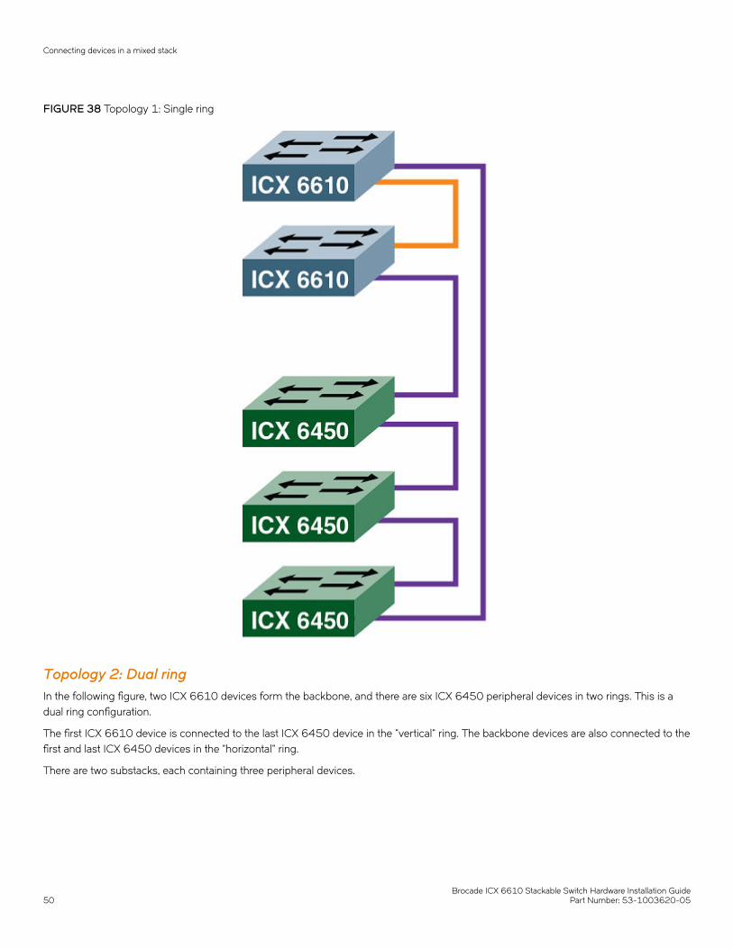
FIGURE 38 Topology 1: Single ring
Topology 2: Dual ringIn the following figure, two ICX 6610 devices form the backbone, and there are six ICX 6450 peripheral devices in two rings. This is adual ring configuration.
The first ICX 6610 device is connected to the last ICX 6450 device in the "vertical" ring. The backbone devices are also connected to thefirst and last ICX 6450 devices in the "horizontal" ring.
There are two substacks, each containing three peripheral devices.
Connecting devices in a mixed stack
Brocade ICX 6610 Stackable Switch Hardware Installation Guide50 Part Number: 53-1003620-05
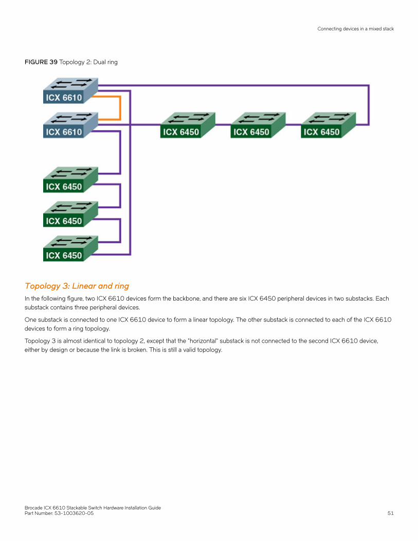
FIGURE 39 Topology 2: Dual ring
Topology 3: Linear and ringIn the following figure, two ICX 6610 devices form the backbone, and there are six ICX 6450 peripheral devices in two substacks. Eachsubstack contains three peripheral devices.
One substack is connected to one ICX 6610 device to form a linear topology. The other substack is connected to each of the ICX 6610devices to form a ring topology.
Topology 3 is almost identical to topology 2, except that the "horizontal" substack is not connected to the second ICX 6610 device,either by design or because the link is broken. This is still a valid topology.
Connecting devices in a mixed stack
Brocade ICX 6610 Stackable Switch Hardware Installation GuidePart Number: 53-1003620-05 51
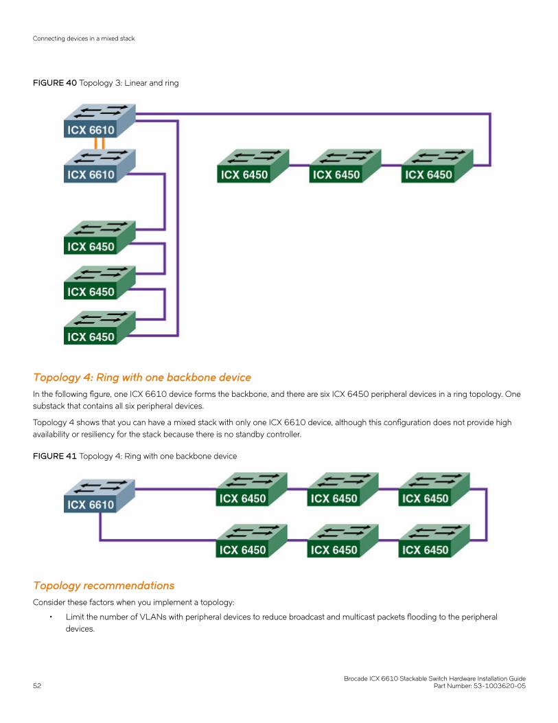
FIGURE 40 Topology 3: Linear and ring
Topology 4: Ring with one backbone deviceIn the following figure, one ICX 6610 device forms the backbone, and there are six ICX 6450 peripheral devices in a ring topology. Onesubstack that contains all six peripheral devices.
Topology 4 shows that you can have a mixed stack with only one ICX 6610 device, although this configuration does not provide highavailability or resiliency for the stack because there is no standby controller.
FIGURE 41 Topology 4: Ring with one backbone device
Topology recommendationsConsider these factors when you implement a topology:
• Limit the number of VLANs with peripheral devices to reduce broadcast and multicast packets flooding to the peripheraldevices.
Connecting devices in a mixed stack
Brocade ICX 6610 Stackable Switch Hardware Installation Guide52 Part Number: 53-1003620-05
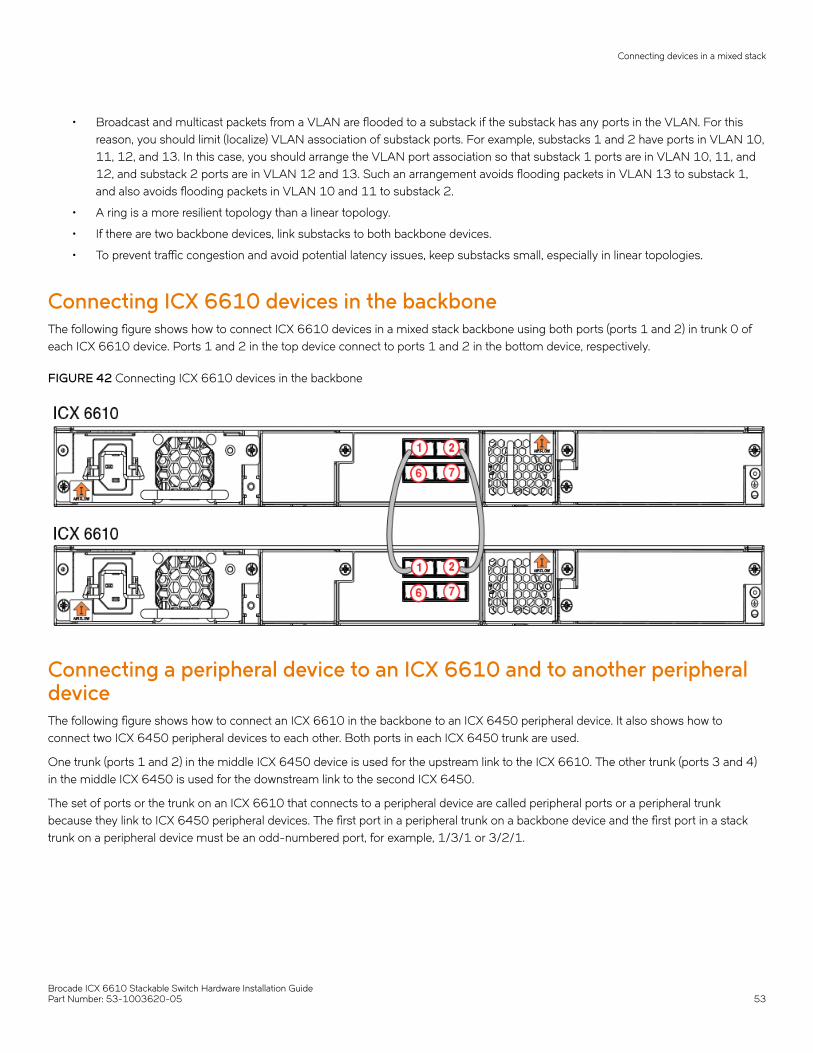
• Broadcast and multicast packets from a VLAN are flooded to a substack if the substack has any ports in the VLAN. For thisreason, you should limit (localize) VLAN association of substack ports. For example, substacks 1 and 2 have ports in VLAN 10,11, 12, and 13. In this case, you should arrange the VLAN port association so that substack 1 ports are in VLAN 10, 11, and12, and substack 2 ports are in VLAN 12 and 13. Such an arrangement avoids flooding packets in VLAN 13 to substack 1,and also avoids flooding packets in VLAN 10 and 11 to substack 2.
• A ring is a more resilient topology than a linear topology.
• If there are two backbone devices, link substacks to both backbone devices.
• To prevent traffic congestion and avoid potential latency issues, keep substacks small, especially in linear topologies.
Connecting ICX 6610 devices in the backboneThe following figure shows how to connect ICX 6610 devices in a mixed stack backbone using both ports (ports 1 and 2) in trunk 0 ofeach ICX 6610 device. Ports 1 and 2 in the top device connect to ports 1 and 2 in the bottom device, respectively.
FIGURE 42 Connecting ICX 6610 devices in the backbone
Connecting a peripheral device to an ICX 6610 and to another peripheraldeviceThe following figure shows how to connect an ICX 6610 in the backbone to an ICX 6450 peripheral device. It also shows how toconnect two ICX 6450 peripheral devices to each other. Both ports in each ICX 6450 trunk are used.
One trunk (ports 1 and 2) in the middle ICX 6450 device is used for the upstream link to the ICX 6610. The other trunk (ports 3 and 4)in the middle ICX 6450 is used for the downstream link to the second ICX 6450.
The set of ports or the trunk on an ICX 6610 that connects to a peripheral device are called peripheral ports or a peripheral trunkbecause they link to ICX 6450 peripheral devices. The first port in a peripheral trunk on a backbone device and the first port in a stacktrunk on a peripheral device must be an odd-numbered port, for example, 1/3/1 or 3/2/1.
Connecting devices in a mixed stack
Brocade ICX 6610 Stackable Switch Hardware Installation GuidePart Number: 53-1003620-05 53
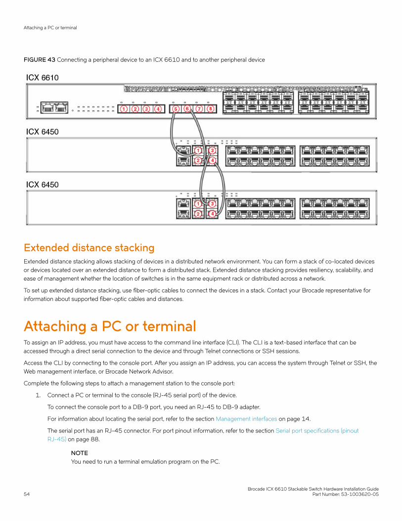
FIGURE 43 Connecting a peripheral device to an ICX 6610 and to another peripheral device
Extended distance stackingExtended distance stacking allows stacking of devices in a distributed network environment. You can form a stack of co-located devicesor devices located over an extended distance to form a distributed stack. Extended distance stacking provides resiliency, scalability, andease of management whether the location of switches is in the same equipment rack or distributed across a network.
To set up extended distance stacking, use fiber-optic cables to connect the devices in a stack. Contact your Brocade representative forinformation about supported fiber-optic cables and distances.
Attaching a PC or terminalTo assign an IP address, you must have access to the command line interface (CLI). The CLI is a text-based interface that can beaccessed through a direct serial connection to the device and through Telnet connections or SSH sessions.
Access the CLI by connecting to the console port. After you assign an IP address, you can access the system through Telnet or SSH, theWeb management interface, or Brocade Network Advisor.
Complete the following steps to attach a management station to the console port:
1. Connect a PC or terminal to the console (RJ-45 serial port) of the device.
To connect the console port to a DB-9 port, you need an RJ-45 to DB-9 adapter.
For information about locating the serial port, refer to the section Management interfaces on page 14.
The serial port has an RJ-45 connector. For port pinout information, refer to the section Serial port specifications (pinoutRJ-45) on page 88.
NOTEYou need to run a terminal emulation program on the PC.
Attaching a PC or terminal
Brocade ICX 6610 Stackable Switch Hardware Installation Guide54 Part Number: 53-1003620-05

2. Launch the terminal emulation program and set the following session parameters:
• Baud: 9600 bps
• Data bits: 8
• Parity: None
• Stop bits: 1
• Flow control: None
The console serial communication port serves as a connection point for management by a PC or SNMP workstation.
Powering on the systemComplete the physical installation before you power on the system.
1. NOTEThe socket should be installed near the equipment and should be easily accessible.
Remove the power cable from the shipping container.
2. Attach the power cable to the power connector.
3. Insert the power cable plug into a 100V-240VAC outlet if your unit uses AC power or a 40-70VDC outlet if your unit uses DCpower.
NOTETo turn the system off, simply unplug the power cable orcables.
Power supplies for the Brocade ICX 6610Each ICX 6610 ships by default with one alternating current (AC) power supply. A second power supply can be added. The ICX 6610can also be ordered with direct current (DC) power supplies.
NOTEAC and DC power supplies cannot be installed and used in the same device. Mismatched power supplies in the same devicecause continual reboot on power up.
If a second power supply is installed and does not match the primary power supply, it will not be operational.
Installing and replacing a power supply unitNOTEPower supplies can be hot swapped with the following precautions.
CAUTIONRemove the power cord from a power supply before you install it in or remove it from the device. Otherwise, the powersupply or the device could be damaged as a result. (The device can be running while a power supply is being installed orremoved, but the power supply itself should not be connected to a power source.)
Power supplies for the Brocade ICX 6610
Brocade ICX 6610 Stackable Switch Hardware Installation GuidePart Number: 53-1003620-05 55

CAUTIONEnsure that the airflow direction of the power supply unit matches that of the installed fan tray. The power supplies and fantrays are clearly labeled with either a green arrow with an "E", or an orange arrow with an "I."
You can run the device with one or two power supply units installed. If you install a second power supply, it is recommended to install asecond fan tray also.
Installing an AC power supplyYou need a #2 Phillips screwdriver and a flat-head screwdriver for installation.
Brocade recommends using an ESD wrist strap during installation.
FIGURE 44 Installing an AC power supply unit
Use the following steps to install an AC power supply in the switch.
1. If replacing a power supply, remove the previously installed power supply from the appropriate slot by removing the two screwswith a flat-head screwdriver.
2. If installing a new power supply into a slot covered with a filler panel:
a) Using a Phillips screwdriver, unscrew the screws on the filler panel.
b) Remove the filler panel.
3. Before opening the package that contains the power supply, touch the bag to the switch casing to discharge any potential staticelectricity.
4. Remove the power supply from the anti-static shielded bag.
5. Holding the power supply level, guide it into the carrier rails on each side and gently push it all the way into the slot, ensuringthat it firmly engages with the connector.
Power supplies for the Brocade ICX 6610
Brocade ICX 6610 Stackable Switch Hardware Installation Guide56 Part Number: 53-1003620-05

6. When you are sure the power supply has properly engaged the connector, tighten the retainer screws to secure the powersupply in the slot.
When the device is powered on, the AC or DC LEDs on the power supply back panel should light green to confirm that the power supplyis correctly installed and supplying power.
You can also verify correct installation by running the show chassis command, as shown in this example:
Device#show chassisThe stack unit 1 chassis info:
Power supply 1 (AC - Regular) present, status okModel Number: 23-0000144-01Serial Number: 028Firmware Ver: APower supply 1 Fan Air Flow Direction: Front to BackPower supply 2 not presentFan 1 ok, speed (auto): [[1]]<->2Fan 2 ok, speed (auto): [[1]]<->2
Fan controlled temperature: 37.5 deg-C
Fan speed switching temperature thresholds:Speed 1: NM<----->70 deg-CSpeed 2: 65<-----> 85 deg-C (shutdown)
Fan 1 Air Flow Direction: Front to BackFan 2 Air Flow Direction: Front to BackMAC-Back Temperature Readings:Current temperature : 37.5 deg-CMAC-Left Temperature Readings:Current temperature : 34.0 deg-CMAC-Right Temperature Readings:Current temperature : 33.0 deg-CMAC-Front Temperature Readings:Current temperature : 33.0 deg-CCPU Temperature Readings:Current temperature : 37.5 deg-CCenter Temperature Readings:Current temperature : 30.5 deg-Csensor A Temperature Readings:Current temperature : 37.5 deg-Csensor B Temperature Readings:Current temperature : 31.0 deg-Csensor C Temperature Readings:Current temperature : 34.5 deg-Csensor D Temperature Readings:Current temperature : 30.5 deg-CWarning level.......: 45.0 deg-CShutdown level......: 85.0 deg-CBoot Prom MAC : 748e.f893.eabeManagement MAC: 748e.f893.eabe
CAUTIONIf you do not install a module or a power supply in a slot, you must keep the slot filler panel in place. If you run the chassiswith an uncovered slot, the system will overheat.
Installing a DC power supplyCAUTIONFor the DC input circuit to the system, make sure there is a 20 Amp circuit breaker, minimum 60 VDC, double pole, on theinput terminal block to the power supply. The input wiring for connection to the product should be copper wire, 12 AWG,marked VW-1, and rated minimum 90°C.
Power supplies for the Brocade ICX 6610
Brocade ICX 6610 Stackable Switch Hardware Installation GuidePart Number: 53-1003620-05 57
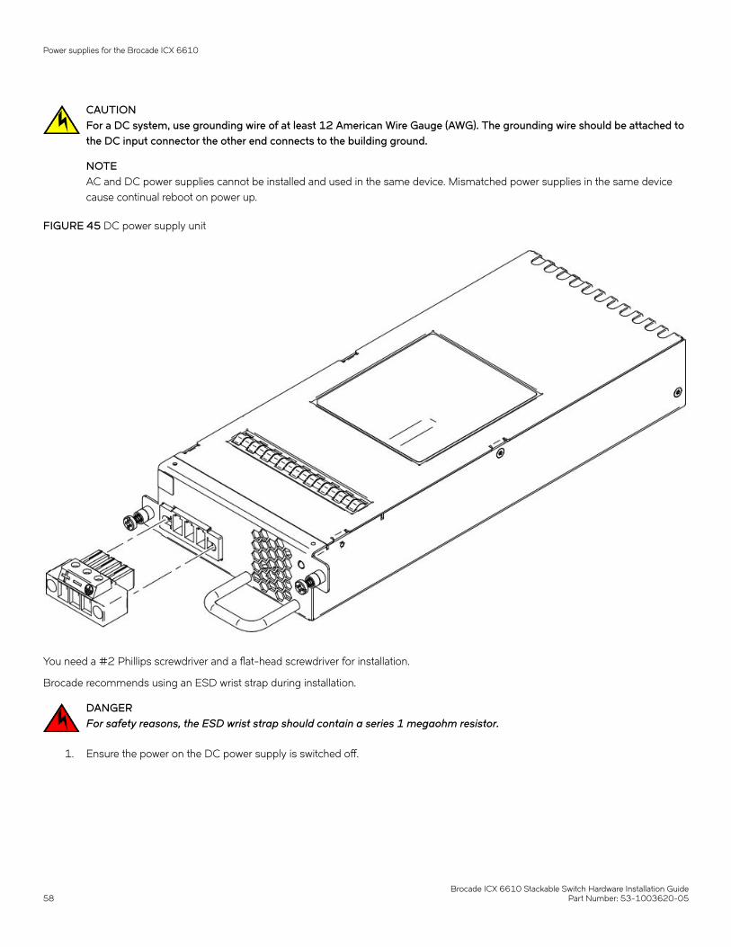
CAUTIONFor a DC system, use grounding wire of at least 12 American Wire Gauge (AWG). The grounding wire should be attached tothe DC input connector the other end connects to the building ground.
NOTEAC and DC power supplies cannot be installed and used in the same device. Mismatched power supplies in the same devicecause continual reboot on power up.
FIGURE 45 DC power supply unit
You need a #2 Phillips screwdriver and a flat-head screwdriver for installation.
Brocade recommends using an ESD wrist strap during installation.
DANGERFor safety reasons, the ESD wrist strap should contain a series 1 megaohm resistor.
1. Ensure the power on the DC power supply is switched off.
Power supplies for the Brocade ICX 6610
Brocade ICX 6610 Stackable Switch Hardware Installation Guide58 Part Number: 53-1003620-05
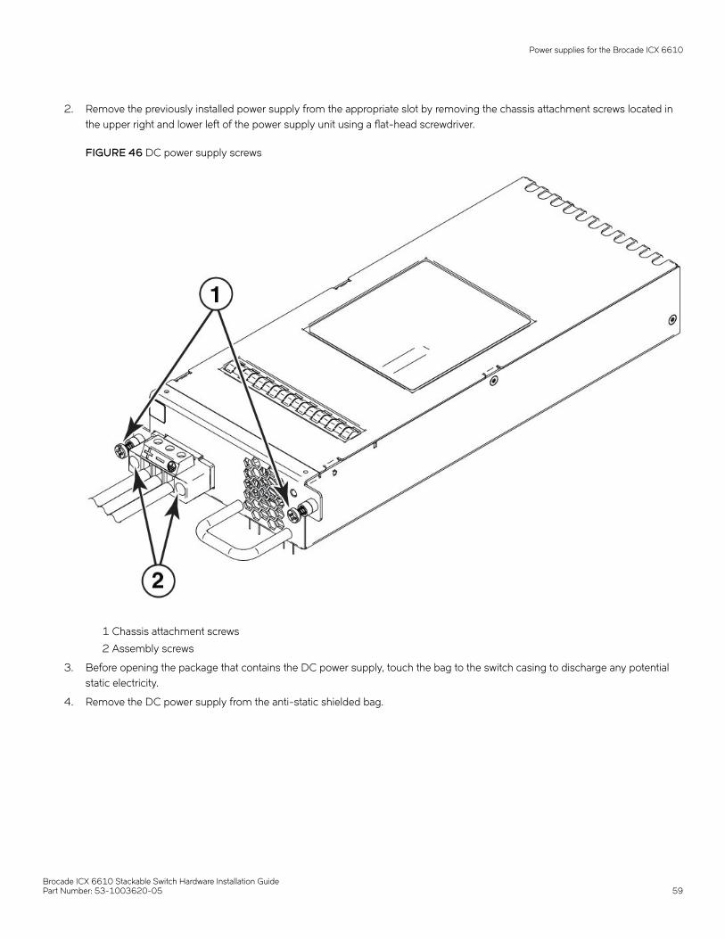
2. Remove the previously installed power supply from the appropriate slot by removing the chassis attachment screws located inthe upper right and lower left of the power supply unit using a flat-head screwdriver.
FIGURE 46 DC power supply screws
1 Chassis attachment screws
2 Assembly screws
3. Before opening the package that contains the DC power supply, touch the bag to the switch casing to discharge any potentialstatic electricity.
4. Remove the DC power supply from the anti-static shielded bag.
Power supplies for the Brocade ICX 6610
Brocade ICX 6610 Stackable Switch Hardware Installation GuidePart Number: 53-1003620-05 59
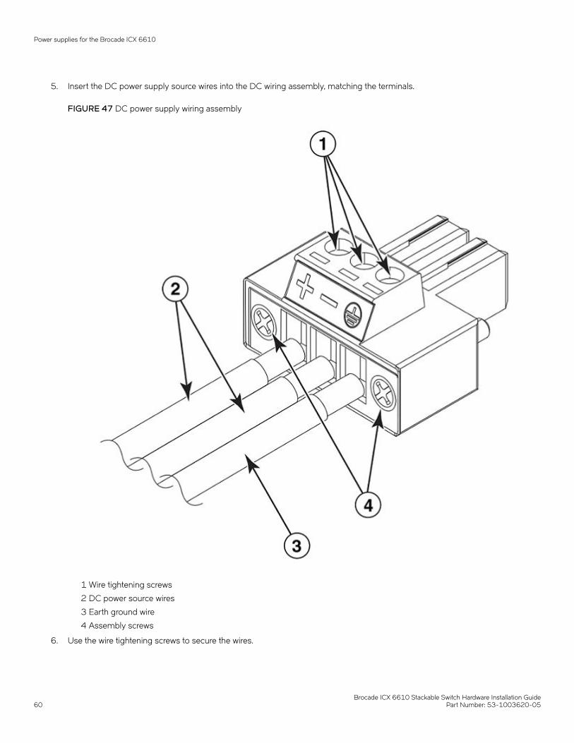
5. Insert the DC power supply source wires into the DC wiring assembly, matching the terminals.
FIGURE 47 DC power supply wiring assembly
1 Wire tightening screws
2 DC power source wires
3 Earth ground wire
4 Assembly screws
6. Use the wire tightening screws to secure the wires.
Power supplies for the Brocade ICX 6610
Brocade ICX 6610 Stackable Switch Hardware Installation Guide60 Part Number: 53-1003620-05
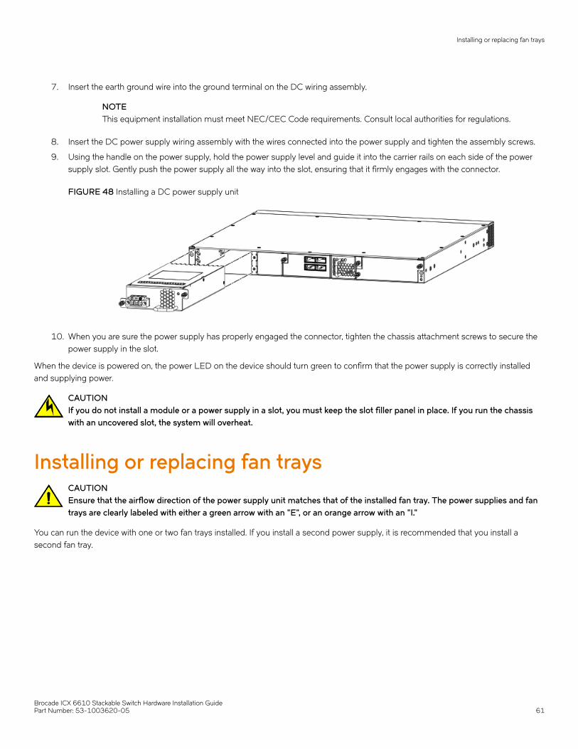
7. Insert the earth ground wire into the ground terminal on the DC wiring assembly.
NOTEThis equipment installation must meet NEC/CEC Code requirements. Consult local authorities for regulations.
8. Insert the DC power supply wiring assembly with the wires connected into the power supply and tighten the assembly screws.
9. Using the handle on the power supply, hold the power supply level and guide it into the carrier rails on each side of the powersupply slot. Gently push the power supply all the way into the slot, ensuring that it firmly engages with the connector.
FIGURE 48 Installing a DC power supply unit
10. When you are sure the power supply has properly engaged the connector, tighten the chassis attachment screws to secure thepower supply in the slot.
When the device is powered on, the power LED on the device should turn green to confirm that the power supply is correctly installedand supplying power.
CAUTIONIf you do not install a module or a power supply in a slot, you must keep the slot filler panel in place. If you run the chassiswith an uncovered slot, the system will overheat.
Installing or replacing fan traysCAUTIONEnsure that the airflow direction of the power supply unit matches that of the installed fan tray. The power supplies and fantrays are clearly labeled with either a green arrow with an "E", or an orange arrow with an "I."
You can run the device with one or two fan trays installed. If you install a second power supply, it is recommended that you install asecond fan tray.
Installing or replacing fan trays
Brocade ICX 6610 Stackable Switch Hardware Installation GuidePart Number: 53-1003620-05 61
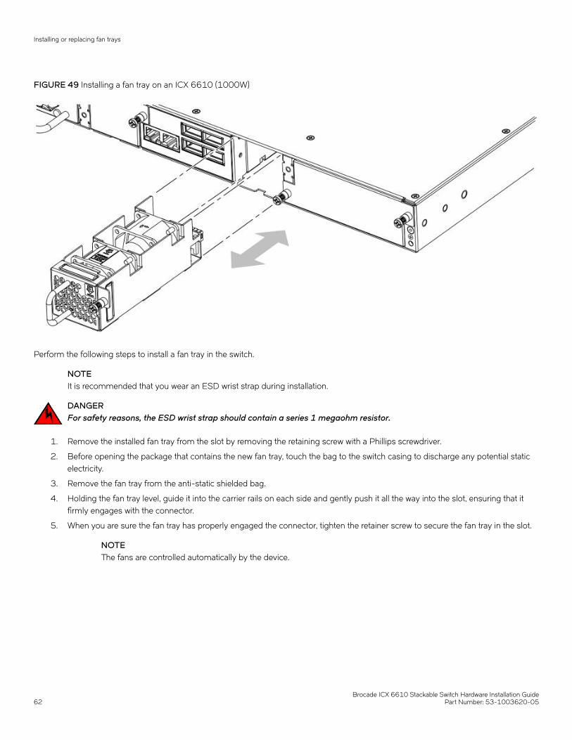
FIGURE 49 Installing a fan tray on an ICX 6610 (1000W)
Perform the following steps to install a fan tray in the switch.
NOTEIt is recommended that you wear an ESD wrist strap during installation.
DANGERFor safety reasons, the ESD wrist strap should contain a series 1 megaohm resistor.
1. Remove the installed fan tray from the slot by removing the retaining screw with a Phillips screwdriver.
2. Before opening the package that contains the new fan tray, touch the bag to the switch casing to discharge any potential staticelectricity.
3. Remove the fan tray from the anti-static shielded bag.
4. Holding the fan tray level, guide it into the carrier rails on each side and gently push it all the way into the slot, ensuring that itfirmly engages with the connector.
5. When you are sure the fan tray has properly engaged the connector, tighten the retainer screw to secure the fan tray in the slot.
NOTEThe fans are controlled automatically by the device.
Installing or replacing fan trays
Brocade ICX 6610 Stackable Switch Hardware Installation Guide62 Part Number: 53-1003620-05
Checking Network Devices and TestingConnectivity
• Assigning permanent passwords................................................................................................................................................................63• Configuring IP addresses...............................................................................................................................................................................64• Connecting network devices.........................................................................................................................................................................68• Testing connectivity.......................................................................................................................................................................................... 72• Troubleshooting network connections......................................................................................................................................................75
DANGERThe procedures in this manual are for qualified service personnel.
Assigning permanent passwordsBy default, the CLI is not protected by passwords. To secure CLI access, Brocade strongly recommends assigning passwords. Refer tothe FastIron Ethernet Switch Administration Guide.
NOTEYou can assign passwords using Brocade Network Advisor if an enable password for a Super User has been configured on thedevice.
The CLI contains the following access levels:
• User EXEC - The level you enter when you first start a CLI session. At this level, you can view some system information, but youcannot configure system or port parameters.
• Privileged EXEC - This level is also called the Enable level and can be secured by a password. You can perform tasks such asmanaging files on the flash module, saving the system configuration to flash, and clearing caches at this level.
• CONFIG - The configuration level. This level lets you configure the system IP address and configure switching and routingfeatures. To access the CONFIG mode, you must already be logged in to the Privileged EXEC level.
You can set the following levels of Enable passwords:
• Super User - Allows complete read-and-write access to the system. This is generally for system administrators and is the onlypassword level that allows you to configure passwords.
NOTEYou must set a Super User password before you can set other types of passwords.
• Port Configuration - Allows read-and-write access for specific ports but not for global (system-wide) parameters.
• Read Only - Allows access to the Privileged EXEC mode and CONFIG mode but only with read access.
Setting passwordsPerform the following steps to set passwords.
1. At the opening CLI prompt, enter the following command to change to the Privileged level of the EXEC mode:
device> enable
Brocade ICX 6610 Stackable Switch Hardware Installation GuidePart Number: 53-1003620-05 63
2. Access the CONFIG mode of the CLI by entering the following command:
device# configure terminaldevice(config)#
3. Enter the following command to set the Super User password:
device(config)# enable super-user-password text
NOTEYou must set the Super User password before you can set other types of passwords.
4. Enter the following commands to set the port configuration and read-only passwords:
device(config)# enable port-config-password textdevice(config)# enable read-only-password text
NOTEIf you forget your Super User password, refer to the task Recovering from a lost password on page 64.
Syntax: enable { super-user-password | read-only-password | port-config-password} text
Passwords can be up to 32 characters long.
Recovering from a lost passwordBy default, the CLI does not require passwords. However, if a password has been configured for the device, but the password has beenlost, you can regain Super User access to the device using the following procedure.
NOTERecovery from a lost password requires direct access to the serial port and a system reset.
Use the following procedure to recover from a lost password.
1. Start a CLI session over the serial interface to the Brocade device.
2. Reboot the device.
3. While the system is booting, before the initial system prompt appears, enter b to enter the boot monitor mode.
4. Enter no password at the prompt. (You cannot abbreviate this command.)
5. Enter boot system flash primary at the prompt. This command causes the device to bypass the system password check.
6. After the console prompt reappears, assign a new password.
Configuring IP addressesYou must configure at least one IP address using the serial connection to the CLI before you can manage the system using the othermanagement interfaces.
Brocade devices support both classical IP network masks (Class A, B, and C subnet masks, and so on) and Classless InterdomainRouting (CIDR) network prefix masks.
• To enter a classical IP network mask, enter the mask in IP address format. For example, enter 10.157.22.99 255.255.255.0for an IP address with a Class C subnet mask.
• To enter a prefix number for a network mask, enter a forward slash (/) and the number of bits in the mask immediately after theIP address. For example, enter 10.157.22.99 /24 for an IP address that has a network mask with 24 significant ("mask") bits.
Configuring IP addresses
Brocade ICX 6610 Stackable Switch Hardware Installation Guide64 Part Number: 53-1003620-05
By default, the CLI displays network masks in classical IP address format (for example, 255.255.255.0). You can change the display tothe prefix format.
Devices running Layer 2 softwareUse the following procedure to configure an IP address on a device running Layer 2 software.
1. At the opening CLI prompt, enter enable.
device> enable
2. Enter the following command at the Privileged EXEC level, and then press Enter. This command erases the factory testconfiguration if it is still present:
device# erase startup-config
CAUTIONUse the erase startup-config command only for new systems. If you enter this command on a system you havealready configured, the command erases the configuration. If you accidentally do erase the configuration on aconfigured system, enter the write memory command to save the running configuration to the startup-config file.
3. Access the global configuration level of the CLI by entering the following command:
device# configure terminaldevice(config)#
4. Configure the IP address and mask for the switch.
device(config)# ip address 10.22.3.44 255.255.255.0
5. Set a default gateway address for the switch.
device(config)# ip default-gateway 10.22.3.1
NOTEYou do not need to assign a default gateway address for single subnet networks.
Syntax: enable [ password ]
Syntax: configure terminal
Syntax: [no] ip address { ip-addr ip-mask | ip-addr/mask-bits }
Syntax: [no] ip default-gateway ip-addr
Devices running Layer 3 softwareBefore attaching equipment to an ICX 6610, you must assign an interface IP address to the subnet on which the device will be located.You must use the serial connection to assign the first IP address. For subsequent addresses, you also can use the CLI through Telnet orSSH.
By default, you can configure up to 24 IP interfaces on each port, virtual interface, and loopback interface. You can increase this amountto up to 64 IP subnet addresses per port by increasing the size of the subnet-per-interface table.
Configuring IP addresses
Brocade ICX 6610 Stackable Switch Hardware Installation GuidePart Number: 53-1003620-05 65
The following procedure shows how to add an IP address and mask to a router port.
1. At the opening CLI prompt, enter enable.
device> enable
2. Enter the following command at the CLI Privileged EXEC level prompt, and then press Enter. This command erases the factorytest configuration if still present:
device# erase startup-config
CAUTIONUse the erase startup-config command only for new systems. If you enter this command on a system you havealready configured, the command erases the configuration. If you accidentally do erase the configuration on aconfigured system, enter the write memory command to save the running configuration to the startup-config file.
3. Access the global configuration level of the CLI by entering the following command:
device# configure terminal device(config)#
4. Configure the IP addresses and mask addresses for the interfaces on the router.
device(config)# interface ethernet 1/1/2device(config-if-e1000-1/1/2)# ip address 10.22.3.44 255.255.255.0
NOTEYou can use the command ip address ip-addr/mask-bits if you know the subnet mask length. In the previousexample, you could enter ip address 10.22.3.44/24.
Syntax: [no] ip address [ ip-addr ip-mask [ secondary ] | ip-addr/mask-bits [ secondary ] ]
Use the secondary parameter if you have already configured an IP address within the same subnet on the interface.
Configuring IP parameters for devices running Layer 3 softwareThis section describes how to configure IP parameters for devices running Layer 3 software.
Configuring IP addresses
You can configure an IP address on the following types of Layer 3 switch interfaces:
• Ethernet port
• Virtual routing interface (also called a Virtual Ethernet or "VE")
• Loopback interface
By default, you can have up to 24 IP addresses on each interface, but you can increase this number to 128 IP addresses.
NOTEOnce you configure a virtual routing interface on a VLAN, you cannot configure Layer 3 interface parameters on individualports in the VLAN. Instead, you must configure the parameters on the virtual routing interface itself.
Configuring IP addresses
Brocade ICX 6610 Stackable Switch Hardware Installation Guide66 Part Number: 53-1003620-05

Assigning an IP address to an Ethernet port
Enter the following commands to assign an IP address to port 1/1/1.
device(config)# interface ethernet 1/1/1device(config-if-1/1/1)# ip address 10.45.6.1 255.255.255.0
You also can enter the IP address and mask in CIDR format, as follows:
device(config-if-1/1/1)# ip address 10.45.6.1/24
Syntax: [no] ip address [ ip-addr | ip-mask ]
or
Syntax: [no] ip address [ ip-addr/mask-bits ]
Assigning an IP address to a loopback interface
Loopback interfaces are always up, regardless of the states of physical interfaces. They can add stability to the network because they arenot subject to route flap problems that can occur due to unstable links between a Layer 3 device and other devices. You can configure upto four loopback interfaces on a Layer 3 device.
You can add up to 24 IP addresses to each loopback interface.
NOTEIf you configure the device to use a loopback interface to communicate with a BGP4 neighbor, you must also configure aloopback interface on the neighbor and configure the neighbor to use that loopback interface to communicate with the Brocadedevice.
To add a loopback interface, enter commands such as those shown in the following example:
device(config)# exitdevice(config)# interface loopback 1device(config-lbif-1)# ip address 10.0.0.1/24
Syntax: interface loopback num
The num parameter specifies the virtual interface number. You can specify from 1 through the maximum number of virtual interfacessupported on the device. To display the maximum number of virtual interfaces supported on the device, enter the show default valuescommand.
Assigning an IP address to a virtual routing interface
A virtual interface is a logical port associated with a Layer 3 Virtual LAN (VLAN) configured on a Layer 3 device. You can configurerouting parameters on the virtual interface to enable the Layer 3 device to route protocol traffic from one Layer 3 VLAN to the other,without using an external router.
NOTEThe device uses the lowest MAC address on the device (the MAC address of port 1 or 1/1/1) as the MAC address for all portswithin all virtual interfaces you configure on the device.
Enter commands similar to the following to add a virtual interface to a VLAN and configure an IP address on the interface.
device(config)# vlan 2 name IP-Subnet_10.1.2.1/24device(config-vlan-2)# untag 1/1/1 to 1/1/4device(config-vlan-2)# router-interface ve1device(config-vlan-2)# interface ve1device(config-vif-1)# ip address 10.1.2.1/24
Configuring IP addresses
Brocade ICX 6610 Stackable Switch Hardware Installation GuidePart Number: 53-1003620-05 67

The first two commands in this example create a Layer 3 protocol-based VLAN name "IP-Subnet_10.1.2.1/24" and add a range ofuntagged ports to the VLAN. The router-interface command creates virtual interface 1 as the routing interface for the VLAN. The lasttwo commands change to the interface configuration level for the virtual interface and assign an IP address to the interface.
Syntax: router-interface ve num
Syntax: interface ve num
Deleting an IP addressEnter a command similar to the following to delete an IP address.
device(config-if-1/1/1)# no ip address 10.1.2.1
This command deletes IP address 10.1.2.1. You do not need to enter the subnet mask.
To delete all IP addresses from an interface, enter the following command:
device(config-if-1/1/1)# no ip address *
Syntax: [no] ip address [ ip-addr | * ]
Connecting network devicesBrocade devices support connections to other vendors’ routers, switches, and hubs, as well other Brocade devices.
ConnectorsFor port pinouts, refer to the section "Pinouts and signalling" in the Hardware Specifications chapter.
CablesRefer to the section Cabling infrastructure on page 28 for cable lengths and types.
Connecting to Ethernet or Fast Ethernet hubsFor copper connections to Ethernet hubs, a 10/100Base-TX or 1000Base-T switch, or another Brocade device, a crossover cable isrequired. If the hub is equipped with an uplink port, it requires a straight-through cable instead of a crossover cable.
NOTEThe 802.3ab standard (automatic MDI or MDIX detection) calls for automatic negotiation of the connection between two1000Base-T ports. In this case, a straight-through cable may work just as well as a crossover cable. For more informationabout this feature, refer to the FastIron Ethernet Switch Security Configuration Guide.
Connecting network devices
Brocade ICX 6610 Stackable Switch Hardware Installation Guide68 Part Number: 53-1003620-05
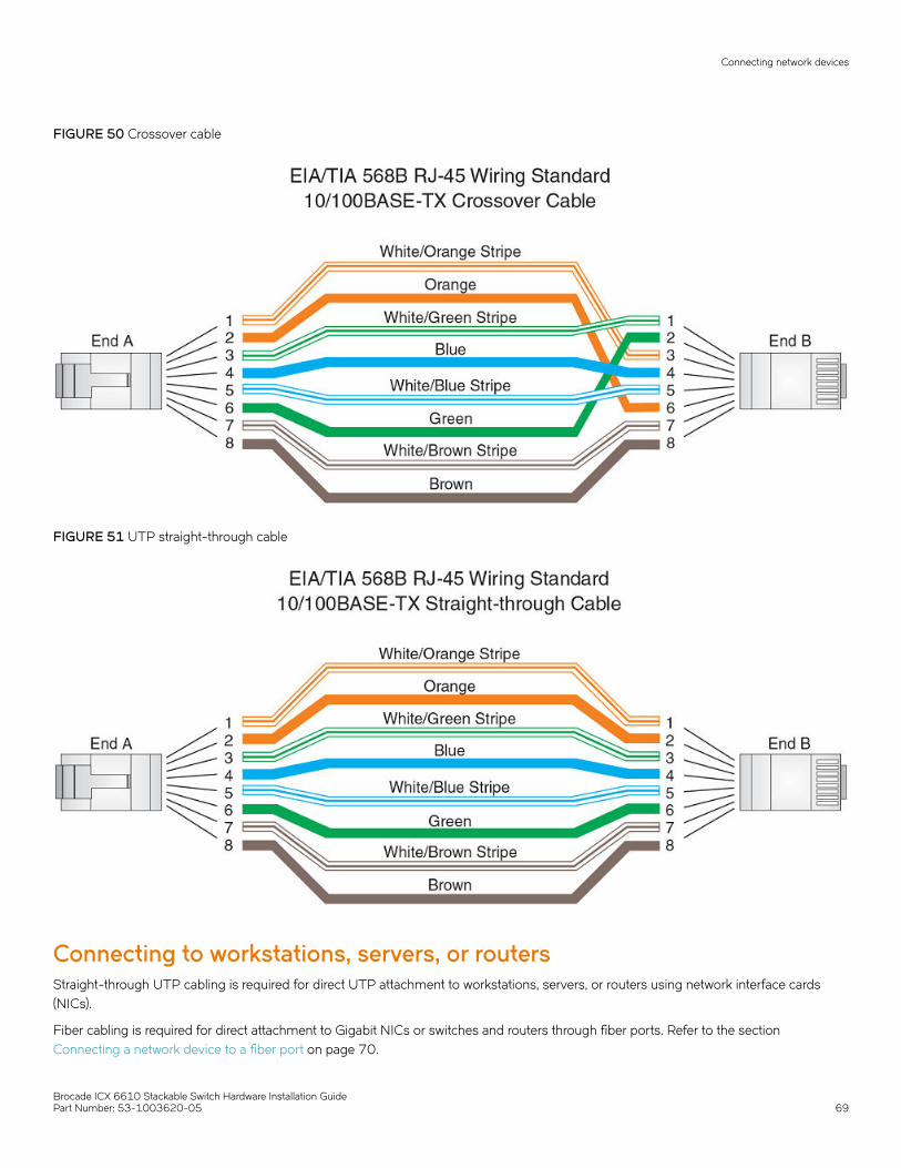
FIGURE 50 Crossover cable
FIGURE 51 UTP straight-through cable
Connecting to workstations, servers, or routersStraight-through UTP cabling is required for direct UTP attachment to workstations, servers, or routers using network interface cards(NICs).
Fiber cabling is required for direct attachment to Gigabit NICs or switches and routers through fiber ports. Refer to the section Connecting a network device to a fiber port on page 70.
Connecting network devices
Brocade ICX 6610 Stackable Switch Hardware Installation GuidePart Number: 53-1003620-05 69
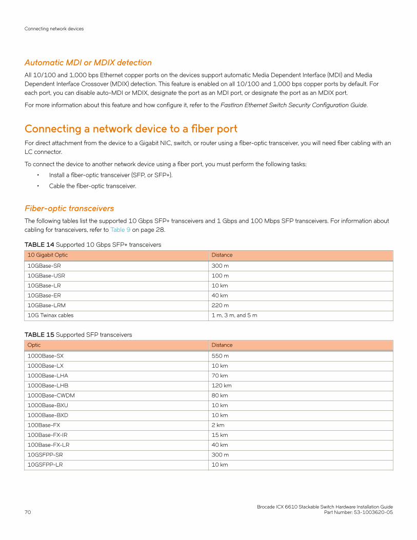
Automatic MDI or MDIX detectionAll 10/100 and 1,000 bps Ethernet copper ports on the devices support automatic Media Dependent Interface (MDI) and MediaDependent Interface Crossover (MDIX) detection. This feature is enabled on all 10/100 and 1,000 bps copper ports by default. Foreach port, you can disable auto-MDI or MDIX, designate the port as an MDI port, or designate the port as an MDIX port.
For more information about this feature and how configure it, refer to the FastIron Ethernet Switch Security Configuration Guide.
Connecting a network device to a fiber portFor direct attachment from the device to a Gigabit NIC, switch, or router using a fiber-optic transceiver, you will need fiber cabling with anLC connector.
To connect the device to another network device using a fiber port, you must perform the following tasks:
• Install a fiber-optic transceiver (SFP, or SFP+).
• Cable the fiber-optic transceiver.
Fiber-optic transceiversThe following tables list the supported 10 Gbps SFP+ transceivers and 1 Gbps and 100 Mbps SFP transceivers. For information aboutcabling for transceivers, refer to Table 9 on page 28.
TABLE 14 Supported 10 Gbps SFP+ transceivers
10 Gigabit Optic Distance
10GBase-SR 300 m
10GBase-USR 100 m
10GBase-LR 10 km
10GBase-ER 40 km
10GBase-LRM 220 m
10G Twinax cables 1 m, 3 m, and 5 m
TABLE 15 Supported SFP transceivers
Optic Distance
1000Base-SX 550 m
1000Base-LX 10 km
1000Base-LHA 70 km
1000Base-LHB 120 km
1000Base-CWDM 80 km
1000Base-BXU 10 km
1000Base-BXD 10 km
100Base-FX 2 km
100Base-FX-IR 15 km
100Base-FX-LR 40 km
10GSFPP-SR 300 m
10GSFPP-LR 10 km
Connecting network devices
Brocade ICX 6610 Stackable Switch Hardware Installation Guide70 Part Number: 53-1003620-05

Installing a transceiverYou can install a new transceiver in an SFP or SFP+ slot while the device is powered on and running.
While installing a transceiver, wear an ESD wrist strap with a plug for connection to a metal surface.
DANGERFor safety reasons, the ESD wrist strap should contain a series 1 megaohm resistor.
DANGERLaser Radiation. Do Not View Directly with Optical Instruments. Class 1M Laser Products.
Use the following steps to install a transceiver:
1. Put on the ESD wrist strap and ground yourself by attaching the clip end to a metal surface (such as an equipment rack) to actas ground.
2. Remove the new transceiver from the protective packaging.
3. Gently insert the transceiver into the slot until it clicks into place. Transceivers are keyed to prevent incorrect insertion.
FIGURE 52 Installing a transceiver
Cabling a fiber-optic transceiverUse the following steps to cable a fiber-optic transceiver.
1. Remove the protective covering from the fiber-optic port connectors and store the covering for future use.
NOTEBefore cabling a fiber-optic transceiver, Brocade strongly recommends cleaning the cable connectors and the portconnectors. For more information, refer to Cleaning the fiber-optic connectors on page 72.
Connecting network devices
Brocade ICX 6610 Stackable Switch Hardware Installation GuidePart Number: 53-1003620-05 71
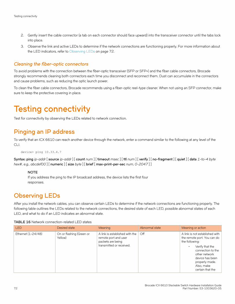
2. Gently insert the cable connector (a tab on each connector should face upward) into the transceiver connector until the tabs lockinto place.
3. Observe the link and active LEDs to determine if the network connections are functioning properly. For more information aboutthe LED indicators, refer to Observing LEDs on page 72.
Cleaning the fiber-optic connectorsTo avoid problems with the connection between the fiber-optic transceiver (SFP or SFP+) and the fiber cable connectors, Brocadestrongly recommends cleaning both connectors each time you disconnect and reconnect them. Dust can accumulate in the connectorsand cause problems, such as reducing the optic launch power.
To clean the fiber cable connectors, Brocade recommends using a fiber-optic reel-type cleaner. When not using an SFP connector, makesure to keep the protective covering in place.
Testing connectivityTest for connectivity by observing the LEDs related to network connection.
Pinging an IP addressTo verify that an ICX 6610 can reach another device through the network, enter a command similar to the following at any level of theCLI.
device> ping 10.33.4.7
Syntax: ping ip-addr [ source ip-addr ] [ count num ] [ timeout msec ] [ ttl num ] [ verify ] [ no-fragment ] [ quiet ] [ data 1-to-4 bytehex#, e.g., abcdef00 ] [ numeric ] [ size byte ] [ brief [ max-print-per-sec num, 0-2047 ] ]
NOTEIf you address the ping to the IP broadcast address, the device lists the first fourresponses.
Observing LEDsAfter you install the network cables, you can observe certain LEDs to determine if the network connections are functioning properly. Thefollowing table outlines the LEDs related to the network connections, the desired state of each LED, possible abnormal states of eachLED, and what to do if an LED indicates an abnormal state.
TABLE 16 Network connection-related LED states
LED Desired state Meaning Abnormal state Meaning or action
Ethernet (1-24/48) On or flashing (Green orYellow)
A link is established with theremote port and userpackets are beingtransmitted or received.
Off A link is not established withthe remote port. You can dothe following:
• Verify that theconnection to theother networkdevice has beenproperly made.Also, makecertain that the
Testing connectivity
Brocade ICX 6610 Stackable Switch Hardware Installation Guide72 Part Number: 53-1003620-05
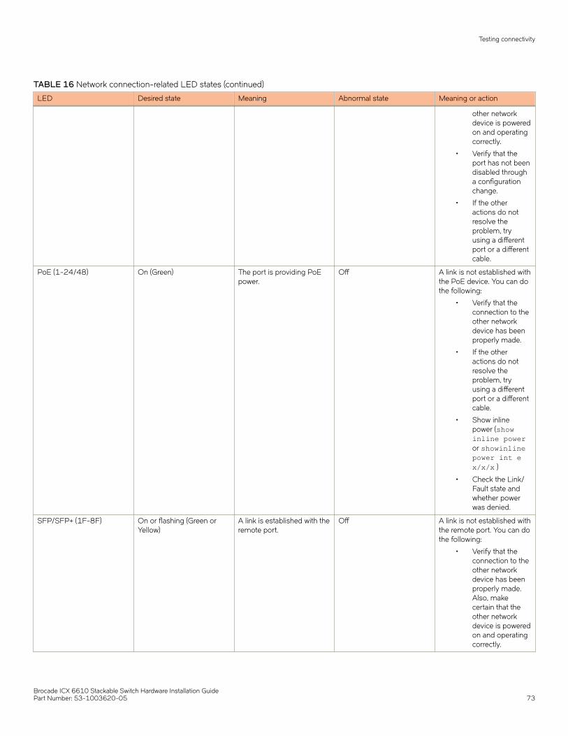
TABLE 16 Network connection-related LED states (continued)
LED Desired state Meaning Abnormal state Meaning or action
other networkdevice is poweredon and operatingcorrectly.
• Verify that theport has not beendisabled througha configurationchange.
• If the otheractions do notresolve theproblem, tryusing a differentport or a differentcable.
PoE (1-24/48) On (Green) The port is providing PoEpower.
Off A link is not established withthe PoE device. You can dothe following:
• Verify that theconnection to theother networkdevice has beenproperly made.
• If the otheractions do notresolve theproblem, tryusing a differentport or a differentcable.
• Show inlinepower (showinline poweror showinlinepower int ex/x/x )
• Check the Link/Fault state andwhether powerwas denied.
SFP/SFP+ (1F-8F) On or flashing (Green orYellow)
A link is established with theremote port.
Off A link is not established withthe remote port. You can dothe following:
• Verify that theconnection to theother networkdevice has beenproperly made.Also, makecertain that theother networkdevice is poweredon and operatingcorrectly.
Testing connectivity
Brocade ICX 6610 Stackable Switch Hardware Installation GuidePart Number: 53-1003620-05 73
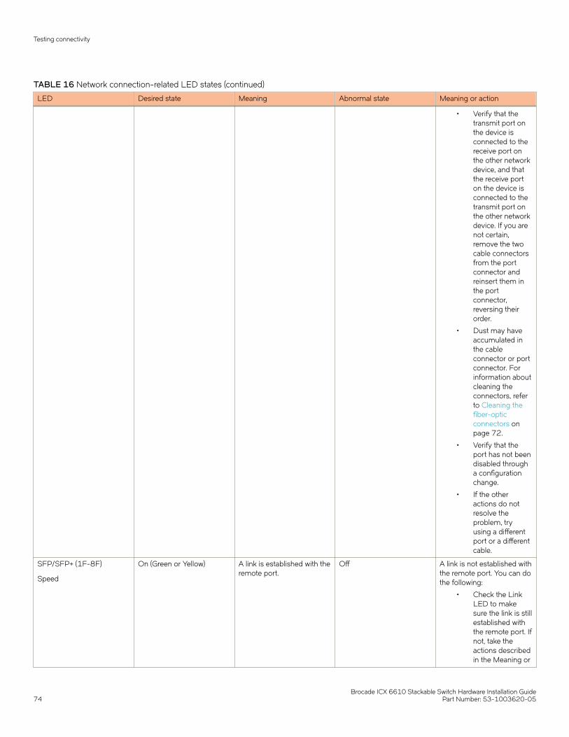
TABLE 16 Network connection-related LED states (continued)
LED Desired state Meaning Abnormal state Meaning or action
• Verify that thetransmit port onthe device isconnected to thereceive port onthe other networkdevice, and thatthe receive porton the device isconnected to thetransmit port onthe other networkdevice. If you arenot certain,remove the twocable connectorsfrom the portconnector andreinsert them inthe portconnector,reversing theirorder.
• Dust may haveaccumulated inthe cableconnector or portconnector. Forinformation aboutcleaning theconnectors, referto Cleaning thefiber-opticconnectors onpage 72.
• Verify that theport has not beendisabled througha configurationchange.
• If the otheractions do notresolve theproblem, tryusing a differentport or a differentcable.
SFP/SFP+ (1F-8F)
Speed
On (Green or Yellow) A link is established with theremote port.
Off A link is not established withthe remote port. You can dothe following:
• Check the LinkLED to makesure the link is stillestablished withthe remote port. Ifnot, take theactions describedin the Meaning or
Testing connectivity
Brocade ICX 6610 Stackable Switch Hardware Installation Guide74 Part Number: 53-1003620-05
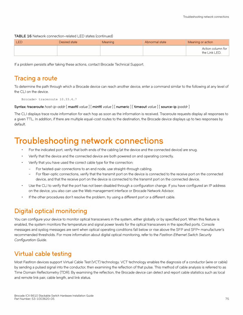
TABLE 16 Network connection-related LED states (continued)
LED Desired state Meaning Abnormal state Meaning or action
Action column forthe Link LED.
If a problem persists after taking these actions, contact Brocade Technical Support.
Tracing a routeTo determine the path through which a Brocade device can reach another device, enter a command similar to the following at any level ofthe CLI on the device.
Brocade> traceroute 10.33.4.7
Syntax: traceroute host-ip-addr [ maxttl value ] [ minttl value ] [ numeric ] [ timeout value ] [ source-ip ipaddr ]
The CLI displays trace route information for each hop as soon as the information is received. Traceroute requests display all responses toa given TTL. In addition, if there are multiple equal-cost routes to the destination, the Brocade device displays up to two responses bydefault.
Troubleshooting network connections• For the indicated port, verify that both ends of the cabling (at the device and the connected device) are snug.
• Verify that the device and the connected device are both powered on and operating correctly.
• Verify that you have used the correct cable type for the connection:
– For twisted-pair connections to an end node, use straight-through cabling.– For fiber-optic connections, verify that the transmit port on the device is connected to the receive port on the connected
device, and that the receive port on the device is connected to the transmit port on the connected device.
• Use the CLI to verify that the port has not been disabled through a configuration change. If you have configured an IP addresson the device, you also can use the Web management interface or Brocade Network Advisor.
• If the other procedures don’t resolve the problem, try using a different port or a different cable.
Digital optical monitoringYou can configure your device to monitor optical transceivers in the system, either globally or by specified port. When this feature isenabled, the system monitors the temperature and signal power levels for the optical transceivers in the specified ports. Consolemessages and syslog messages are sent when optical operating conditions fall below or rise above the SFP and SFP+ manufacturer’srecommended thresholds. For more information about digital optical monitoring, refer to the FastIron Ethernet Switch SecurityConfiguration Guide.
Virtual cable testingMost FastIron devices support Virtual Cable Test (VCT) technology. VCT technology enables the diagnosis of a conductor (wire or cable)by sending a pulsed signal into the conductor, then examining the reflection of that pulse. This method of cable analysis is referred to asTime Domain Reflectometry (TDR). By examining the reflection, the Brocade device can detect and report cable statistics such as localand remote link pair, cable length, and link status.
Troubleshooting network connections
Brocade ICX 6610 Stackable Switch Hardware Installation GuidePart Number: 53-1003620-05 75

Virtual Cable Testing configuration notes• VCT is supported on copper ports only. It is not supported on fiber ports.
• VCT is only supported when Ethernet port speed is configured to Auto. VCT does not work on ports with fixed speeds.
• VCT is not supported on the following:
– ICX 6610-24F– SX-FI24GPP– SX-FI48GPP– SX-FI2XG– SX-FI8XG– SX-FI24HF
• The port to which the cable is connected must be enabled when you issue the command to diagnose the cable. If the port isdisabled, the command is rejected.
• If the port is operating at 100 Mbps half-duplex, the TDR test on one pair will fail.
• If the remote pair is set to forced 100 Mbps, any change in MDI/MDIX may cause the device to interpret the MultilevelThreshold-3 (MLT-3) as a reflected pulse, in which case, the device will report a faulty condition. In this scenario, it isrecommended that you run the TDR test a few times, clearing the registers before each test, for accurate results.
Virtual Cable Test command syntaxTo diagnose a cable using TDR, enter commands such as the following at the Privileged EXEC level of the CLI.
device# phy cable-diagnostics tdr 1/1/1
The clear-diag tdr command clears results of any previous TDR test from test registers for port 1/1/1 (port 1 on slot 1 on device 1).
NOTEIt is recommended that you clear the TDR test registers before each test.
device# clear cable-diagnostics tdr 1/1/1
The command in the previous example diagnoses the cable attached to port 1/1/1.
When you issue the phy cable-diagnostics command, the command brings the port down for a second or two, and then immediatelybrings the port back up.
Syntax: clear cable-diagnostics tdr stackid/slot/port
Syntax: phy cable-diagnostics tdr stackid/slot/port
Viewing the results of the cable analysisTo display the results of the cable analysis, enter a command such as the one shown in the following examples at the Privileged EXEClevel of the CLI.
In the first example, the command displays TDR test results for port 1, slot 1 on device 1 in the stack. The results indicate that the port isdown or the cable is not connected.
device>show cable-diagnostics tdr 1/1/1Port Speed Local pair Pair Length Remote pair Pair status--------- ----- ---------- ----------- ----------- ------------- ----- ------- ----- ------ ----------01 UNKWN Pair A <=3 M Open Pair B <=3 M Open Pair C <=3 M Open Pair D <=3 M Open
Troubleshooting network connections
Brocade ICX 6610 Stackable Switch Hardware Installation Guide76 Part Number: 53-1003620-05
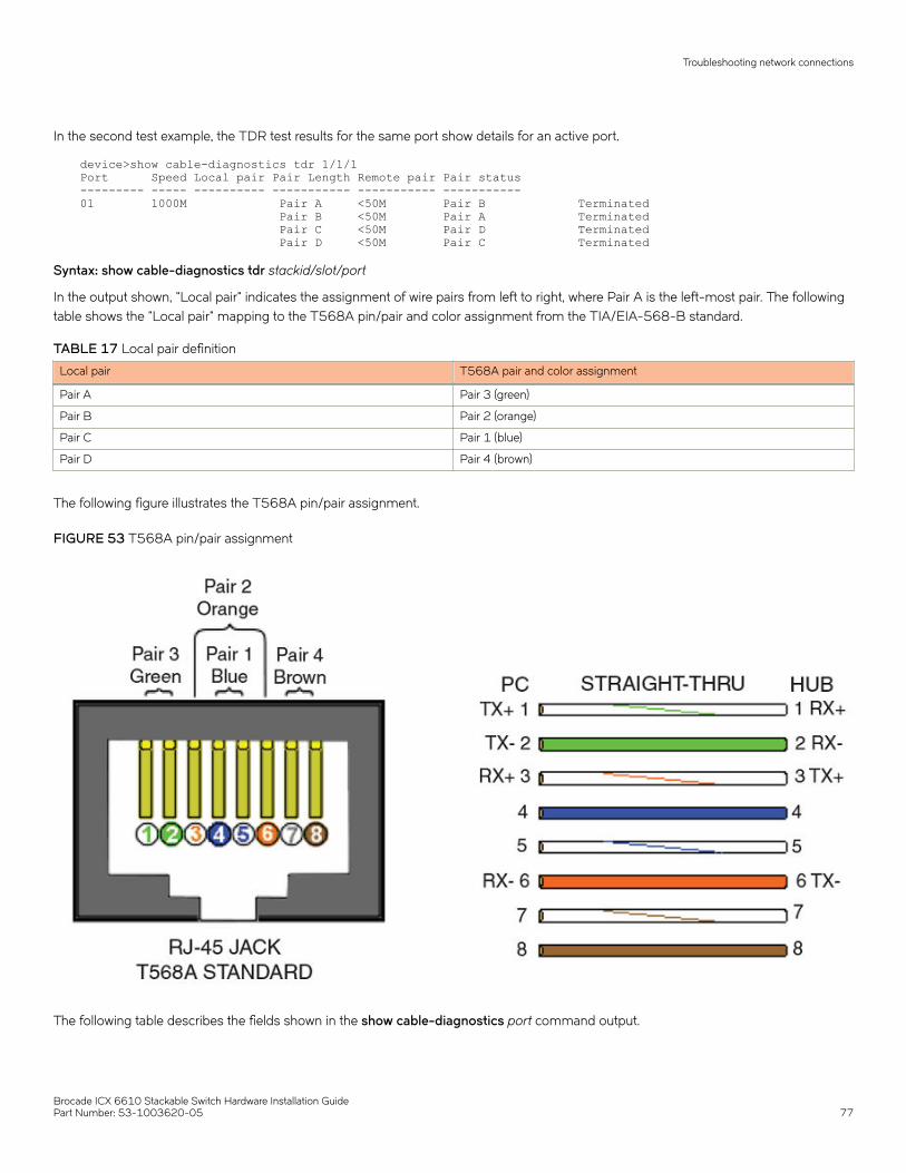
In the second test example, the TDR test results for the same port show details for an active port.
device>show cable-diagnostics tdr 1/1/1Port Speed Local pair Pair Length Remote pair Pair status--------- ----- ---------- ----------- ----------- -----------01 1000M Pair A <50M Pair B Terminated Pair B <50M Pair A Terminated Pair C <50M Pair D Terminated Pair D <50M Pair C Terminated
Syntax: show cable-diagnostics tdr stackid/slot/port
In the output shown, "Local pair" indicates the assignment of wire pairs from left to right, where Pair A is the left-most pair. The followingtable shows the "Local pair" mapping to the T568A pin/pair and color assignment from the TIA/EIA-568-B standard.
TABLE 17 Local pair definition
Local pair T568A pair and color assignment
Pair A Pair 3 (green)
Pair B Pair 2 (orange)
Pair C Pair 1 (blue)
Pair D Pair 4 (brown)
The following figure illustrates the T568A pin/pair assignment.
FIGURE 53 T568A pin/pair assignment
The following table describes the fields shown in the show cable-diagnostics port command output.
Troubleshooting network connections
Brocade ICX 6610 Stackable Switch Hardware Installation GuidePart Number: 53-1003620-05 77

TABLE 18 Cable statistics
Field Meaning
Port The port that was tested.
Speed The port current line speed.
Local pair The local link name. Refer to the previous local pair definition table.
Pair Length The cable length when terminated, or the distance to the point of faultwhen the line is not up.
Remote pair The remote link name.
Pair status The status of the link. This field displays one of the following:
• Terminated: The link is up.
• Shorted: A short is detected in the cable.
• Open: An opening is detected in the cable.
• ImpedMis: The impedance is mismatched.
• Failed: The TDR test failed.
Troubleshooting network connections
Brocade ICX 6610 Stackable Switch Hardware Installation Guide78 Part Number: 53-1003620-05

Managing the ICX 6610 Hardware• Managing temperature settings...................................................................................................................................................................79• Removing MAC address entries..................................................................................................................................................................82• Displaying ICX 6610 CPU usage.............................................................................................................................................................. 82• Hardware maintenance schedule................................................................................................................................................................82• Removing a copper or fiber-optic module..............................................................................................................................................83• Cabling a fiber-optic module........................................................................................................................................................................ 84• Cleaning the fiber-optic connectors...........................................................................................................................................................84
DANGERThe procedures in this manual are for qualified service personnel.
Managing temperature settingsThis section describes how to display temperature settings on the device and how to change the temperature warning and shutdownlevels.
Using the temperature sensorThe device contains temperature sensors that the software reads based on a configurable device poll time. To protect the device fromoverheating, the following temperature threshold levels exist:
• The warning level is the temperature at which the device generates a Syslog message and SNMP trap. It is configurable.
• The shutdown level is the temperature at which the device reboots. It is set by the device and is not configurable.
• The fan speed settings are set by the device, and are not configurable.
Displaying the temperatureTo display the temperature of a device, enter the show chassis command at any level of the CLI.
NOTEThe displayed temperature reflects the temperature of the board inside thedevice.
device#show chassisThe stack unit 1 chassis info:Power supply 1 not presentPower supply 2 (NA - AC - Regular) present, status okPower supply 2 Fan Air Flow Direction: Front to BackFan 1 ok, speed (auto): [[1]]<->2Fan 2 not presentFan controlled temperature: 53.5 deg-CFan speed switching temperature thresholds: Speed 1: NM<----->80 deg-C Speed 2: 75<-----> 85 deg-C (shutdown)Fan 1 Air Flow Direction: Front to Back MAC 1 Temperature Readings: Current temperature : 32.5 deg-CMAC 2 Temperature Readings: Current temperature : 46.5 deg-CCPU Temperature Readings:
Brocade ICX 6610 Stackable Switch Hardware Installation GuidePart Number: 53-1003620-05 79

Current temperature : 39.5 deg-Csensor A Temperature Readings: Current temperature : 28.5 deg-Csensor B Temperature Readings: Current temperature : 45.0 deg-Csensor C Temperature Readings: Current temperature : 33.0 deg-Cstacking card Temperature Readings: Current temperature : 53.5 deg-C Warning level.......: 75.0 deg-C Shutdown level......: 85.0 deg-CBoot Prom MAC : 001b.0387.0124Management MAC: 001b.0387.0124
Syntax: show chassis
Displaying syslog messages for temperatureThe software sends a syslog message and an SNMP trap if the temperature crosses the warning or shutdown thresholds. The followingmethods describe how to view the system log on the device. If you have configured the device to use a syslog server or SNMP trapreceiver, see the documentation for the server or receiver.
To display the system log, enter the show log command at any CLI level.
device# show logSyslog logging: enabled (0 messages dropped, 0 flushes, 0 overruns)Buffer logging: level ACDMEINW, 8 messages loggedlevel code: A=alert C=critical D=debugging M=emergency E=errorI=informational N=notification W=warningStatic Log Buffer:Dynamic Log Buffer (50 entries):at 0 days 0 hours 2 minutes 0 seconds, level alertTemperature 48.0 C degrees, warning level 45.0 C degrees, shutdown level 55.0 C degreesat 0 days 0 hours 1 minutes 0 seconds, level alertTemperature 40.0 C degrees, warning level 35.0 C degrees, shutdown level 45.0 C degrees
Changing the temperature warning levelTo change the temperature at which the device sends a syslog message and an SNMP trap, enter a command similar to the following atthe Privileged EXEC level of the CLI:
device# temperature warning 1 83
Syntax: temperature warning stack-id value
The stack-id can be a value from 1 through 8.
The value variable is the temperature warning level in Celsius. The maximum value of the temperature warning level is 5 degrees belowthe shutdown level, which is automatically set by the device.
If you change the device hardware configuration (for example, by adding a fan tray), the device may change the temperature shutdownlevel the next time it boots. This can result in the temperature warning level being higher than the temperature shutdown level. If thishappens, a warning message is displayed during bootup.
Information on incorrect temperature warning levels also appears when you enter the show chassis command to display chassis statusas shown in the following example.
device#show chassisThe stack unit 1 chassis info: Power supply 1 not presentPower supply 2 (AC - Regular) present, status ok Model Number: 23-0000144-01 Serial Number: 02E
Managing temperature settings
Brocade ICX 6610 Stackable Switch Hardware Installation Guide80 Part Number: 53-1003620-05
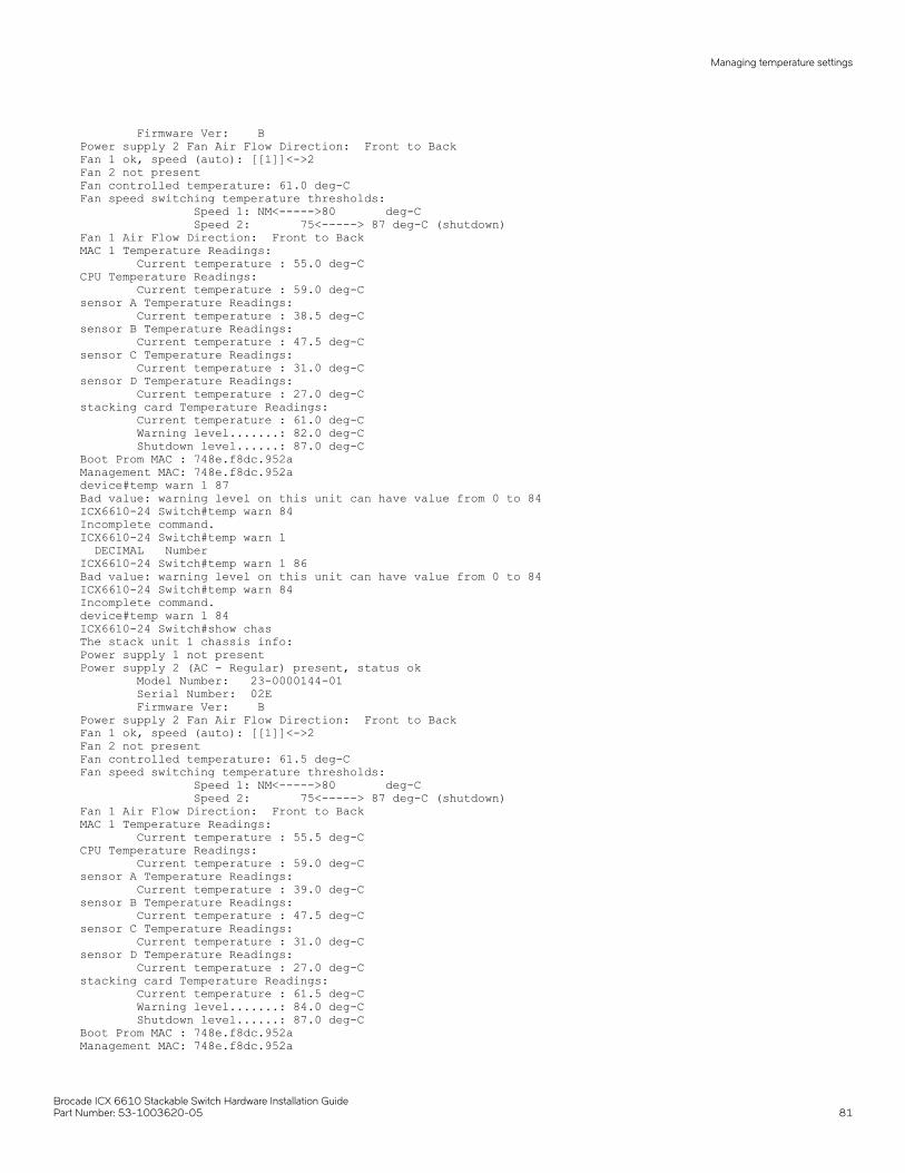
Firmware Ver: BPower supply 2 Fan Air Flow Direction: Front to BackFan 1 ok, speed (auto): [[1]]<->2Fan 2 not presentFan controlled temperature: 61.0 deg-CFan speed switching temperature thresholds: Speed 1: NM<----->80 deg-C Speed 2: 75<-----> 87 deg-C (shutdown)Fan 1 Air Flow Direction: Front to Back MAC 1 Temperature Readings: Current temperature : 55.0 deg-CCPU Temperature Readings: Current temperature : 59.0 deg-Csensor A Temperature Readings: Current temperature : 38.5 deg-Csensor B Temperature Readings: Current temperature : 47.5 deg-Csensor C Temperature Readings: Current temperature : 31.0 deg-Csensor D Temperature Readings: Current temperature : 27.0 deg-Cstacking card Temperature Readings: Current temperature : 61.0 deg-C Warning level.......: 82.0 deg-C Shutdown level......: 87.0 deg-CBoot Prom MAC : 748e.f8dc.952aManagement MAC: 748e.f8dc.952adevice#temp warn 1 87Bad value: warning level on this unit can have value from 0 to 84ICX6610-24 Switch#temp warn 84Incomplete command.ICX6610-24 Switch#temp warn 1 DECIMAL NumberICX6610-24 Switch#temp warn 1 86Bad value: warning level on this unit can have value from 0 to 84ICX6610-24 Switch#temp warn 84Incomplete command.device#temp warn 1 84ICX6610-24 Switch#show chasThe stack unit 1 chassis info: Power supply 1 not presentPower supply 2 (AC - Regular) present, status ok Model Number: 23-0000144-01 Serial Number: 02E Firmware Ver: BPower supply 2 Fan Air Flow Direction: Front to BackFan 1 ok, speed (auto): [[1]]<->2Fan 2 not presentFan controlled temperature: 61.5 deg-CFan speed switching temperature thresholds: Speed 1: NM<----->80 deg-C Speed 2: 75<-----> 87 deg-C (shutdown)Fan 1 Air Flow Direction: Front to Back MAC 1 Temperature Readings: Current temperature : 55.5 deg-CCPU Temperature Readings: Current temperature : 59.0 deg-Csensor A Temperature Readings: Current temperature : 39.0 deg-Csensor B Temperature Readings: Current temperature : 47.5 deg-Csensor C Temperature Readings: Current temperature : 31.0 deg-Csensor D Temperature Readings: Current temperature : 27.0 deg-Cstacking card Temperature Readings: Current temperature : 61.5 deg-C Warning level.......: 84.0 deg-C Shutdown level......: 87.0 deg-CBoot Prom MAC : 748e.f8dc.952aManagement MAC: 748e.f8dc.952a
Managing temperature settings
Brocade ICX 6610 Stackable Switch Hardware Installation GuidePart Number: 53-1003620-05 81

Changing the temperature poll timeBy default, the software polls the temperature sensor every 60 seconds to get the current temperature. This poll rate is controlled by thedevice poll time, which also controls how often the software polls other system components.
To change the poll time, enter a command similar to the following at the global CONFIG level.
device(config)# chassis poll-time 200
Syntax: chassis poll-time value
The value variable can be from 0 through 65535 seconds.
Removing MAC address entriesYou can remove the following types of learned MAC address entries from the system MAC address table:
• All MAC address entries
• All MAC address entries for a specified Ethernet port
• All MAC address entries for a specified VLAN
• A specified MAC address entry in all VLANs
For example, to remove entries for the MAC address 0000.0080.00d in all VLANs, enter the following command at the PrivilegedEXEC level of the CLI.
device# clear mac-address 0000.0080.00d
Syntax: clear mac-address [ mac-address | ethernet port-num | vlan number]
If you enter the clear mac-address command without any parameters, the software removes all MAC entries.
Use the mac-address variable to remove a specified MAC address from all VLANs. Specify the MAC address in the following format:HHHH.HHHH.HHHH.
Use the ethernet port-num parameter to remove all MAC addresses for a specified Ethernet port.
Use the vlan number parameter to remove all MAC addresses for a specified VLAN.
Displaying ICX 6610 CPU usageYou can display the amount of the CPU in use. To do so, enter the show cpu command at any level of the CLI.
device# show cpu31 percent busy, from 3248 sec ago1 sec avg: 10 percent busy5 sec avg: 10 percent busy60 sec avg: 10 percent busy300 sec avg: 10 percent busy
Syntax: show cpu
Hardware maintenance scheduleICX 6610 switch hardware components require minimal maintenance. Brocade recommends cleaning the fiber-optic connectors on afiber-optic port and the connected fiber cable each time you disconnect the cable.
Removing MAC address entries
Brocade ICX 6610 Stackable Switch Hardware Installation Guide82 Part Number: 53-1003620-05
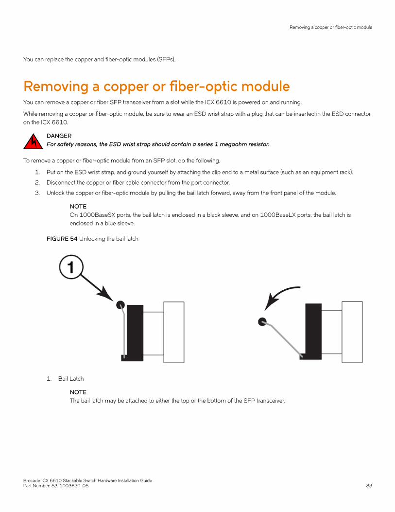
You can replace the copper and fiber-optic modules (SFPs).
Removing a copper or fiber-optic moduleYou can remove a copper or fiber SFP transceiver from a slot while the ICX 6610 is powered on and running.
While removing a copper or fiber-optic module, be sure to wear an ESD wrist strap with a plug that can be inserted in the ESD connectoron the ICX 6610.
DANGERFor safety reasons, the ESD wrist strap should contain a series 1 megaohm resistor.
To remove a copper or fiber-optic module from an SFP slot, do the following.
1. Put on the ESD wrist strap, and ground yourself by attaching the clip end to a metal surface (such as an equipment rack).
2. Disconnect the copper or fiber cable connector from the port connector.
3. Unlock the copper or fiber-optic module by pulling the bail latch forward, away from the front panel of the module.
NOTEOn 1000BaseSX ports, the bail latch is enclosed in a black sleeve, and on 1000BaseLX ports, the bail latch isenclosed in a blue sleeve.
FIGURE 54 Unlocking the bail latch
1. Bail Latch
NOTEThe bail latch may be attached to either the top or the bottom of the SFP transceiver.
Removing a copper or fiber-optic module
Brocade ICX 6610 Stackable Switch Hardware Installation GuidePart Number: 53-1003620-05 83
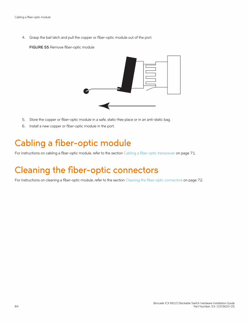
4. Grasp the bail latch and pull the copper or fiber-optic module out of the port.
FIGURE 55 Remove fiber-optic module
5. Store the copper or fiber-optic module in a safe, static-free place or in an anti-static bag.
6. Install a new copper or fiber-optic module in the port.
Cabling a fiber-optic moduleFor instructions on cabling a fiber-optic module, refer to the section Cabling a fiber-optic transceiver on page 71.
Cleaning the fiber-optic connectorsFor instructions on cleaning a fiber-optic module, refer to the section Cleaning the fiber-optic connectors on page 72.
Cabling a fiber-optic module
Brocade ICX 6610 Stackable Switch Hardware Installation Guide84 Part Number: 53-1003620-05
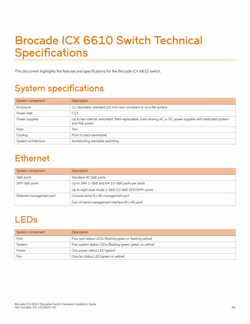
Brocade ICX 6610 Switch TechnicalSpecificationsThis document highlights the features and specifications for the Brocade ICX 6610 switch.
System specificationsSystem component Description
Enclosure 1U, stackable, standard 19-inch rack compliant or on a flat surface
Power inlet C14
Power supplies Up to two internal, redundant, field-replaceable, load-sharing AC or DC power supplies with dedicated systemand PoE power
Fans Two
Cooling Front to back (reversible)
System architecture Nonblocking stackable switching
EthernetSystem component Description
GbE ports Standard 40 GbE ports
SFP GbE ports Up to 384 1-GbE and 64 10-GbE ports per stack
Up to eight dual-mode 1 GbE/10 GbE SFP/SFP+ ports
Ethernet management port Console serial RJ-45 management port
Out-of-band management Interface (RJ-45 port)
LEDsSystem component Description
Port Four port status LEDs (flashing green or flashing yellow)
System Five system status LEDs (flashing green, green, or yellow)
Power One power status LED (green)
Fan One fan status LED (green or yellow)
Brocade ICX 6610 Stackable Switch Hardware Installation GuidePart Number: 53-1003620-05 85

OtherSystem component Description
Serial cable Console serial RJ-45 management port
RJ-45 connector 10/100/1000 Mbps RJ-45 Ethernet port
Weight and physical dimensionsModel Height Width Depth Weight
ICX 6610-24 4.4 cm
1.7 inches
42.9 cm
16.89 inches
40.64 cm
16 inches
6.35 kg
13.97 lb
ICX 6610-24F 4.4 cm
1.7 inches
42.9 cm
16.89 inches
40.64 cm
16 inches
6.48 kg
14.26 lb
ICX 6610-24P 4.4 cm
1.7 inches
42.9 cm
16.89 inches
40.64 cm
16 inches
7.24 kg
15.93 lb
ICX 6610-48 4.4 cm
1.7 inches
42.9 cm
16.89 inches
40.64 cm
16 inches
6.77 kg
14.90 lb
ICX 6610-48P 4.4 cm
1.7 inches
42.9 cm
16.89 inches
40.64 cm
16 inches
7.55 kg
16.60 lb
Environmental requirementsCondition Operational Non-operational
Ambient temperature 0°C to 45°C (32°F to 113°F) -25º C to 70º C (-13º F to 158° F)
Relative humidity (non-condensing)
10% to 93% at 50°C (120°F) 95% maximum
Altitude (above sea level) 0 to 3000 m (10,000 ft) 0 to 4500 m (15,000 ft)
Airflow Front to back (reversible) N/A
Operating noise 39.6 dB to 48.7 dB N/A
Power supply specifications (per PSU)Power supplymodel
Maximum outputpower rating (DC)
Input voltage Input linefrequency
Maximum inputcurrent
Input lineprotection
Maximum inrushcurrent
RPS15-E
RPS15-I
250 W 100 - 240 VAC 50/60 Hz 4.0 A - 2.0 A Line & NeutralFused
35 A peak for <10ms, 10 ms - 150ms <25 A peak,>150 ms the ACinput current will beless than the ratingof the input fusesand other
Other
Brocade ICX 6610 Stackable Switch Hardware Installation Guide86 Part Number: 53-1003620-05
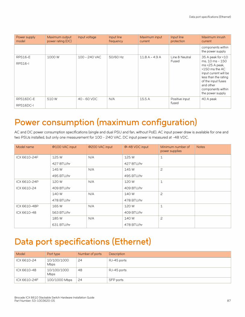
Power supplymodel
Maximum outputpower rating (DC)
Input voltage Input linefrequency
Maximum inputcurrent
Input lineprotection
Maximum inrushcurrent
components withinthe power supply
RPS16-E
RPS16-I
1000 W 100 - 240 VAC 50/60 Hz 11.8 A - 4.9 A Line & NeutralFused
35 A peak for <10ms, 10 ms - 150ms <25 A peak,>150 ms the ACinput current will beless than the ratingof the input fusesand othercomponents withinthe power supply
RPS16DC-E
RPS16DC-I
510 W 40 - 60 VDC N/A 15.5 A Positive inputfused
40 A peak
Power consumption (maximum configuration)AC and DC power consumption specifications (single and dual PSU and fan, without PoE). AC input power draw is available for one andtwo PSUs installed, but only one measurement for 100 - 240 VAC. DC input power is measured at -48 VDC.
Model name @100 VAC input @200 VAC input @-48 VDC input Minimum number ofpower supplies
Notes
ICX 6610-24F 125 W
427 BTU/hr
N/A 125 W
427 BTU/hr
1
145 W
495 BTU/hr
N/A 145 W
495 BTU/hr
2
ICX 6610-24P
ICX 6610-24
120 W
409 BTU/hr
N/A 120 W
409 BTU/hr
1
140 W
478 BTU/hr
N/A 140 W
478 BTU/hr
2
ICX 6610-48P
ICX 6610-48
165 W
563 BTU/hr
N/A 120 W
409 BTU/hr
1
185 W
631 BTU/hr
N/A 140 W
478 BTU/hr
2
Data port specifications (Ethernet)Model Port type Number of ports Description
ICX 6610-24 10/100/1000Mbps
24 RJ-45 ports
ICX 6610-48 10/100/1000Mbps
48 RJ-45 ports
ICX 6610-24F 100/1000 Mbps 24 SFP ports
Data port specifications (Ethernet)
Brocade ICX 6610 Stackable Switch Hardware Installation GuidePart Number: 53-1003620-05 87

Model Port type Number of ports Description
1/10 GbE
40 Gbps
8
4
Dual-mode SFP/SFP+ ports
QSFP stacking ports
ICX 6610-24P 10/100/1000(PoE+)
24 (one powersupply)
Maximum PoE Class 3 ports
Maximum PoE+ ports
ICX 6610-48P 10/100/1000(PoE+)
48 (one powersupply)
48 (two powersupplies)
Maximum PoE Class 3 ports
Maximum PoE+ ports
Serial port specifications (pinout RJ-45)Pin Signal Description
1 Not supported N/A
2 Not supported N/A
3 UART0_TXD Transmit data
4 GND Logic ground
5 GND Logic ground
6 UART0_RXD Receive data
7 Not supported N/A
8 Not supported N/A
Serial port specifications (protocol)Parameter Value
Baud 9600 bps
Data bits 8
Parity None
Stop bits 1
Flow control None
Regulatory compliance (EMC)• FCC Part 15, Subpart B (Class A)
• EN 55022 (CE mark) (Class A)
• EN 55024 (CE mark) (Immunity) for Information Technology Equipment
• ICES-003 (Canada) (Class A)
• AS/NZ 55022 (Australia) (Class A)
• VCCI (Japan) (Class A)
• EN 61000-3-2
Serial port specifications (pinout RJ-45)
Brocade ICX 6610 Stackable Switch Hardware Installation Guide88 Part Number: 53-1003620-05

• EN 61000-3-3
• EN 61000-6-1
Regulatory compliance (safety)• CAN/CSA-C22.2 No. 60950-1-07/UL60950-1 - Safety of Information Technology Equipment
• EN 60825-1 Safety of Laser Products - Part 1: Equipment Classification, Requirements and User's Guide
• EN 60825-2 Safety of Laser Products - Part 2: Safety of Optical Fibre Communications Systems
• EN 60950-1, IEC 60950-1 Safety of Information Technology Equipment
Regulatory compliance (environmental)• 2011/65/EU - Restriction of the use of certain hazardous substance in electrical and electronic equipment (EU RoHS)
• 2012/19/EU - Waste electrical and electronic equipment (EU WEEE)
• 94/62/EC - packaging and packaging waste (EU)
• 2006/66/EC - batteries and accumulators and waste batteries and accumulators (EU battery directive)
• 1907/2006 of the European Parliament and of the Council of 18 December 2006 concerning the Registration, Evaluation,Authorisation and Restriction of Chemicals (EU REACH)
• Section 1502 of the Dodd-Frank Wall Street Reform and Consumer Protection Act of 2010 - U.S. Conflict Minerals
• 30/2011/TT-BCT - Vietnam circular
• SJ/T 11363-2006 Requirements for Concentration Limits for Certain Hazardous Substances in EIPs (China)
• SJ/T 11364-2006 Marking for the Control of Pollution Caused by EIPs (China)
Regulatory compliance (environmental)
Brocade ICX 6610 Stackable Switch Hardware Installation GuidePart Number: 53-1003620-05 89

Brocade ICX 6610 Stackable Switch Hardware Installation Guide90 Part Number: 53-1003620-05
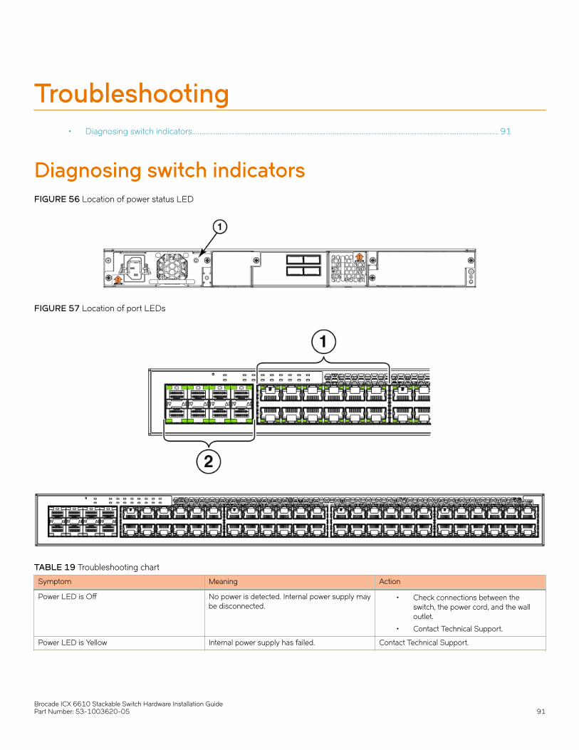
Troubleshooting• Diagnosing switch indicators........................................................................................................................................................................ 91
Diagnosing switch indicatorsFIGURE 56 Location of power status LED
FIGURE 57 Location of port LEDs
TABLE 19 Troubleshooting chart
Symptom Meaning Action
Power LED is Off No power is detected. Internal power supply maybe disconnected.
• Check connections between theswitch, the power cord, and the walloutlet.
• Contact Technical Support.
Power LED is Yellow Internal power supply has failed. Contact Technical Support.
Brocade ICX 6610 Stackable Switch Hardware Installation GuidePart Number: 53-1003620-05 91

TABLE 19 Troubleshooting chart (continued)
Symptom Meaning Action
Diag LED is Yellow The switch self test has detected a fault. • Power cycle the switch to try and clearthe condition. If the condition persists,contact Technical Support.
Link LED is Off No power is detected on the link. • Verify that the switch and attacheddevice are powered on.
• Be sure the cable is plugged into boththe switch and the correspondingdevice.
• Verify that the proper cable type isused and its length does not exceedspecified limits.
• Check the adapter on the attacheddevice and cable connections forpossible defects. Replace thedefective adapter or cable ifnecessary.
Power and cooling problemsIf the power LED does not turn on when the power cord is plugged in, you may have a problem with the power outlet, power cord, orinternal power supply. However, if the unit powers off after running for a while, check for loose power connections, power losses, orsurges at the power outlet, and verify that the fans on the unit are unobstructed and running prior to shutdown. You can also checkwhether fans are obstructed using the show chassis CLI command.
If the device is continuously rebooting, check the temperature of the system. If you have dual power supplies installed, be sure that theymatch. DC and AC power supplies installed in the same unit will cause continuous rebooting.
If you still cannot isolate the problem, the internal power supply may be defective. In this case, contact Technical Support for assistance.
InstallationVerify that all system components have been properly installed. If one or more components appear to be malfunctioning (such as thepower cord or network cabling), test them in an alternate environment where you are sure that all the other components are functioningproperly.
In-band accessYou can access the management agent in the switch from anywhere within the attached network using Telnet, SSH, or other networkmanagement software. However, you must first configure the switch with a valid IP address, subnet mask, and default gateway. If youhave trouble establishing a link to the management agent, check to see if you have a valid network connection. Then verify that youentered the correct IP address. Also be sure the port through which you are connecting to the switch has not been disabled. If it has notbeen disabled, then check the network cabling that runs between your remote location and the switch.
Diagnosing switch indicators
Brocade ICX 6610 Stackable Switch Hardware Installation Guide92 Part Number: 53-1003620-05

Regulatory Statements• BSMI statement (Taiwan)................................................................................................................................................................................93• Canadian requirements................................................................................................................................................................................... 93• China CC statement..........................................................................................................................................................................................94• Europe and Australia (CISPR 22 Class A Warning)............................................................................................................................ 94• FCC warning (US only).................................................................................................................................................................................... 95• Germany................................................................................................................................................................................................................95• KCC statement (Republic of Korea)............................................................................................................................................................95• VCCI statement.................................................................................................................................................................................................. 95
BSMI statement (Taiwan)
Warning:
This is Class A product. In a domestic environment this product may cause radio interference in which case the user may be required totake adequate measures.
Canadian requirementsThis Class A digital apparatus meets all requirements of the Canadian Interference-Causing Equipment Regulations, ICES-003 Class A.
Cet appareil numérique de la classe A est conforme à la norme NMB-003 du Canada.
Brocade ICX 6610 Stackable Switch Hardware Installation GuidePart Number: 53-1003620-05 93

China CC statement
Europe and Australia (CISPR 22 Class A Warning)This is a Class A product. In a domestic environment this product may cause radio interference in which case the user may be required totake adequate measures.
China CC statement
Brocade ICX 6610 Stackable Switch Hardware Installation Guide94 Part Number: 53-1003620-05

FCC warning (US only)This equipment has been tested and complies with the limits for a Class A computing device pursuant to Part 15 of the FCC Rules.These limits are designed to provide reasonable protection against harmful interference when the equipment is operated in a commercialenvironment.
This equipment generates, uses, and can radiate radio frequency energy, and if not installed and used in accordance with the instructionmanual, might cause harmful interference to radio communications. Operation of this equipment in a residential area is likely to causeharmful interference, in which case the user will be required to correct the interference at the user’s own expense.
GermanyMachine noise information regulation - 3. GPSGV, the highest sound pressure level value is 53.0 dB(A) in accordance with EN ISO7779.
Maschinenlärminformations-Verordnung - 3. GPSGV, der höchste Schalldruckpegel beträgt 53.0 dB(A) gemäss EN ISO 7779.
KCC statement (Republic of Korea)
Class A device (Broadcasting Communication Device for Office Use): This device obtained EMC registration for office use (Class A), andmay be used in places other than home. Sellers and/or users need to take note of this.
VCCI statement
This is a Class A product based on the standard of the Voluntary Control Council for Interference by Information Technology Equipment(VCCI). If this equipment is used in a domestic environment, radio disturbance might arise. When such trouble occurs, the user might berequired to take corrective actions.
VCCI statement
Brocade ICX 6610 Stackable Switch Hardware Installation GuidePart Number: 53-1003620-05 95

Brocade ICX 6610 Stackable Switch Hardware Installation Guide96 Part Number: 53-1003620-05

Cautions and Danger Notices• Cautions.................................................................................................................................................................................................................97• Danger Notices................................................................................................................................................................................................101
CautionsA Caution statement alerts you to situations that can be potentially hazardous to you or cause damage to hardware, firmware, software, ordata.
Ein Vorsichthinweis warnt Sie vor potenziellen Personengefahren oder Beschädigung der Hardware, Firmware, Software oder auch voreinem möglichen Datenverlust
Un message de mise en garde vous alerte sur des situations pouvant présenter un risque potentiel de dommages corporels ou dedommages matériels, logiciels ou de perte de données.
Un mensaje de precaución le alerta de situaciones que pueden resultar peligrosas para usted o causar daños en el hardware, el firmware,el software o los datos.
General cautionsCAUTIONDo not install the device in an environment where the operating ambient temperature might exceed 45°C (113°F).
VORSICHT Das Gerät darf nicht in einer Umgebung mit einer Umgebungsbetriebstemperatur von über 45°C (113°F) installiert werden.
MISE EN GARDE N'installez pas le dispositif dans un environnement où la température d'exploitation ambiante risque de dépasser 45°C(113°F).
PRECAUCIÓN No instale el instrumento en un entorno en el que la temperatura ambiente de operación pueda exceder los 45°C (113°F).
CAUTIONMake sure the airflow around the front, sides, and back of the device is notrestricted.
VORSICHT Stellen Sie sicher, dass an der Vorderseite, den Seiten und an der Rückseite der Luftstrom nicht behindert wird.
MISE EN GARDE Vérifiez que rien ne restreint la circulation d'air devant, derrière et sur les côtés du dispositif et qu'elle peut se faire librement.
PRECAUCIÓN Asegúrese de que el flujo de aire en las inmediaciones de las partes anterior, laterales y posterior del instrumento no estérestringido.
CAUTIONEnsure that the airflow direction of the power supply unit matches that of the installed fan tray. The power supplies and fantrays are clearly labeled with either a green arrow with an "E", or an orange arrow with an "I."
VORSICHT Vergewissern Sie sich, dass die Luftstromrichtung des Netzteils der eingebauten Lüftereinheit entspricht. Die Netzteile undLüftereinheiten sind eindeutig mit einem grünen Pfeil und dem Buchstaben "E" oder einem orangefarbenen Pfeil mit demBuchstaben "I" gekennzeichnet.
MISE EN GARDE Veillez à ce que le sens de circulation de l'air du bloc d'alimentation corresponde à celui du tiroir de ventilation installé. Lesblocs d'alimentation et les tiroirs de ventilation sont étiquetés d'une flèche verte avec un "E " ou d'une flèche orange avec un "I ".
Brocade ICX 6610 Stackable Switch Hardware Installation GuidePart Number: 53-1003620-05 97
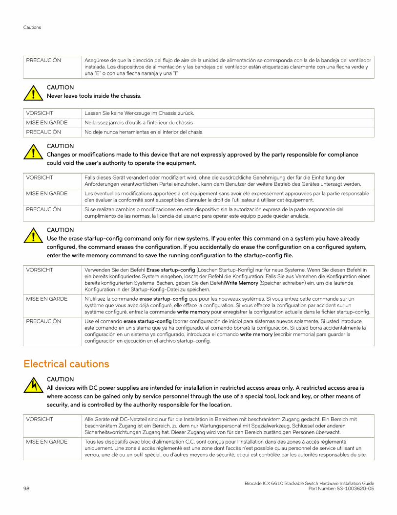
PRECAUCIÓN Asegúrese de que la dirección del flujo de aire de la unidad de alimentación se corresponda con la de la bandeja del ventiladorinstalada. Los dispositivos de alimentación y las bandejas del ventilador están etiquetadas claramente con una flecha verde yuna "E" o con una flecha naranja y una "I".
CAUTIONNever leave tools inside the chassis.
VORSICHT Lassen Sie keine Werkzeuge im Chassis zurück.
MISE EN GARDE Ne laissez jamais d'outils à l'intérieur du châssis
PRECAUCIÓN No deje nunca herramientas en el interior del chasis.
CAUTIONChanges or modifications made to this device that are not expressly approved by the party responsible for compliancecould void the user's authority to operate the equipment.
VORSICHT Falls dieses Gerät verändert oder modifiziert wird, ohne die ausdrückliche Genehmigung der für die Einhaltung derAnforderungen verantwortlichen Partei einzuholen, kann dem Benutzer der weitere Betrieb des Gerätes untersagt werden.
MISE EN GARDE Les éventuelles modifications apportées à cet équipement sans avoir été expressément approuvées par la partie responsabled'en évaluer la conformité sont susceptibles d'annuler le droit de l'utilisateur à utiliser cet équipement.
PRECAUCIÓN Si se realizan cambios o modificaciones en este dispositivo sin la autorización expresa de la parte responsable delcumplimiento de las normas, la licencia del usuario para operar este equipo puede quedar anulada.
CAUTIONUse the erase startup-config command only for new systems. If you enter this command on a system you have alreadyconfigured, the command erases the configuration. If you accidentally do erase the configuration on a configured system,enter the write memory command to save the running configuration to the startup-config file.
VORSICHT Verwenden Sie den Befehl Erase startup-config (Löschen Startup-Konfig) nur für neue Systeme. Wenn Sie diesen Befehl inein bereits konfiguriertes System eingeben, löscht der Befehl die Konfiguration. Falls Sie aus Versehen die Konfiguration einesbereits konfigurierten Systems löschen, geben Sie den BefehlWrite Memory (Speicher schreiben) ein, um die laufendeKonfiguration in der Startup-Konfig-Datei zu speichern.
MISE EN GARDE N'utilisez la commande erase startup-config que pour les nouveaux systèmes. Si vous entrez cette commande sur unsystème que vous avez déjà configuré, elle efface la configuration. Si vous effacez la configuration par accident sur unsystème configuré, entrez la commande write memory pour enregistrer la configuration actuelle dans le fichier startup-config.
PRECAUCIÓN Use el comando erase startup-config (borrar configuración de inicio) para sistemas nuevos solamente. Si usted introduceeste comando en un sistema que ya ha configurado, el comando borrará la configuración. Si usted borra accidentalmente laconfiguración en un sistema ya configurado, introduzca el comando write memory (escribir memoria) para guardar laconfiguración en ejecución en el archivo startup-config.
Electrical cautionsCAUTIONAll devices with DC power supplies are intended for installation in restricted access areas only. A restricted access area iswhere access can be gained only by service personnel through the use of a special tool, lock and key, or other means ofsecurity, and is controlled by the authority responsible for the location.
VORSICHT Alle Geräte mit DC-Netzteil sind nur für die Installation in Bereichen mit beschränktem Zugang gedacht. Ein Bereich mitbeschränktem Zugang ist ein Bereich, zu dem nur Wartungspersonal mit Spezialwerkzeug, Schlüssel oder anderenSicherheitsvorrichtungen Zugang hat. Dieser Zugang wird von für den Bereich zuständigen Personen überwacht.
MISE EN GARDE Tous les dispositifs avec bloc d'alimentation C.C. sont conçus pour l'installation dans des zones à accès réglementéuniquement. Une zone à accès réglementé est une zone dont l'accès n'est possible qu'au personnel de service utilisant unverrou, une clé ou un outil spécial, ou d'autres moyens de sécurité, et qui est contrôlée par les autorités responsables du site.
Cautions
Brocade ICX 6610 Stackable Switch Hardware Installation Guide98 Part Number: 53-1003620-05
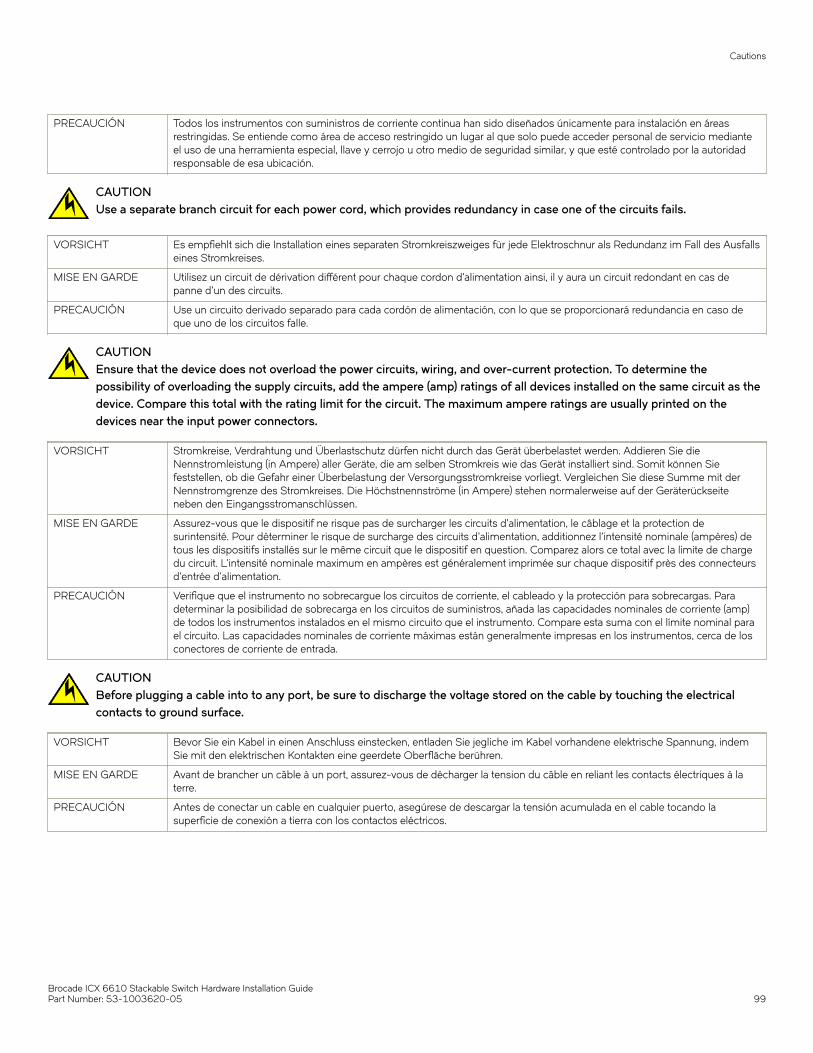
PRECAUCIÓN Todos los instrumentos con suministros de corriente continua han sido diseñados únicamente para instalación en áreasrestringidas. Se entiende como área de acceso restringido un lugar al que solo puede acceder personal de servicio medianteel uso de una herramienta especial, llave y cerrojo u otro medio de seguridad similar, y que esté controlado por la autoridadresponsable de esa ubicación.
CAUTIONUse a separate branch circuit for each power cord, which provides redundancy in case one of the circuits fails.
VORSICHT Es empfiehlt sich die Installation eines separaten Stromkreiszweiges für jede Elektroschnur als Redundanz im Fall des Ausfallseines Stromkreises.
MISE EN GARDE Utilisez un circuit de dérivation différent pour chaque cordon d’alimentation ainsi, il y aura un circuit redondant en cas depanne d’un des circuits.
PRECAUCIÓN Use un circuito derivado separado para cada cordón de alimentación, con lo que se proporcionará redundancia en caso deque uno de los circuitos falle.
CAUTIONEnsure that the device does not overload the power circuits, wiring, and over-current protection. To determine thepossibility of overloading the supply circuits, add the ampere (amp) ratings of all devices installed on the same circuit as thedevice. Compare this total with the rating limit for the circuit. The maximum ampere ratings are usually printed on thedevices near the input power connectors.
VORSICHT Stromkreise, Verdrahtung und Überlastschutz dürfen nicht durch das Gerät überbelastet werden. Addieren Sie dieNennstromleistung (in Ampere) aller Geräte, die am selben Stromkreis wie das Gerät installiert sind. Somit können Siefeststellen, ob die Gefahr einer Überbelastung der Versorgungsstromkreise vorliegt. Vergleichen Sie diese Summe mit derNennstromgrenze des Stromkreises. Die Höchstnennströme (in Ampere) stehen normalerweise auf der Geräterückseiteneben den Eingangsstromanschlüssen.
MISE EN GARDE Assurez-vous que le dispositif ne risque pas de surcharger les circuits d'alimentation, le câblage et la protection desurintensité. Pour déterminer le risque de surcharge des circuits d'alimentation, additionnez l'intensité nominale (ampères) detous les dispositifs installés sur le même circuit que le dispositif en question. Comparez alors ce total avec la limite de chargedu circuit. L'intensité nominale maximum en ampères est généralement imprimée sur chaque dispositif près des connecteursd'entrée d'alimentation.
PRECAUCIÓN Verifique que el instrumento no sobrecargue los circuitos de corriente, el cableado y la protección para sobrecargas. Paradeterminar la posibilidad de sobrecarga en los circuitos de suministros, añada las capacidades nominales de corriente (amp)de todos los instrumentos instalados en el mismo circuito que el instrumento. Compare esta suma con el límite nominal parael circuito. Las capacidades nominales de corriente máximas están generalmente impresas en los instrumentos, cerca de losconectores de corriente de entrada.
CAUTIONBefore plugging a cable into to any port, be sure to discharge the voltage stored on the cable by touching the electricalcontacts to ground surface.
VORSICHT Bevor Sie ein Kabel in einen Anschluss einstecken, entladen Sie jegliche im Kabel vorhandene elektrische Spannung, indemSie mit den elektrischen Kontakten eine geerdete Oberfläche berühren.
MISE EN GARDE Avant de brancher un câble à un port, assurez-vous de décharger la tension du câble en reliant les contacts électriques à laterre.
PRECAUCIÓN Antes de conectar un cable en cualquier puerto, asegúrese de descargar la tensión acumulada en el cable tocando lasuperficie de conexión a tierra con los contactos eléctricos.
Cautions
Brocade ICX 6610 Stackable Switch Hardware Installation GuidePart Number: 53-1003620-05 99

CAUTIONRemove the power cord from a power supply before you install it in or remove it from the device. Otherwise, the powersupply or the device could be damaged as a result. (The device can be running while a power supply is being installed orremoved, but the power supply itself should not be connected to a power source.)
VORSICHT Nehmen Sie vor dem Anschließen oder Abtrennen des Geräts das Stromkabel vom Netzteil ab. Ansonsten könnten dasNetzteil oder das Gerät beschädigt werden. (Das Gerät kann während des Anschließens oder Annehmens des Netzteilslaufen. Nur das Netzteil sollte nicht an eine Stromquelle angeschlossen sein.)
MISE EN GARDE Enlevez le cordon d'alimentation d'un bloc d'alimentation avant de l'installer ou de l'enlever du dispositif. Sinon, le blocd'alimentation ou le dispositif risque d'être endommagé. (Le dispositive peut être en train de fonctionner lorsque vous installezou enlevez un bloc d'alimentation, mais le bloc d'alimentation lui-même ne doit pas être connecté à une sourced'alimentation.)
PRECAUCIÓN Retire el cordón de corriente del suministro de corriente antes de instalarlo o retírarlo del instrumento. De no hacerse así, elsuministro de corriente o el instrumento podrían resultar dañados. (El instrumento puede estar encendido mientras se instalao retira un suministro de corriente, pero el suministro de corriente en sí no deberá conectado a la corriente).
CAUTIONIf you do not install a module or a power supply in a slot, you must keep the slot filler panel in place. If you run the chassiswith an uncovered slot, the system will overheat.
VORSICHT Falls kein Modul oder Netzteil im Steckplatz installiert wird, muss die Steckplatztafel angebracht werden. Wenn ein Steckplatznicht abgedeckt wird, läuft das System heiß.
MISE EN GARDE Si vous n’installez pas de module ou de bloc d'alimentation dans un slot, vous devez laisser le panneau du slot en place. Sivous faites fonctionner le châssis avec un slot découvert, le système surchauffera.
PRECAUCIÓN Si no instala un módulo o un fuente de alimentación en la ranura, deberá mantener el panel de ranuras en su lugar. Si pone enfuncionamiento el chasis con una ranura descubierta, el sistema sufrirá sobrecalentamiento.
CAUTIONFor the DC input circuit to the system, make sure there is a 20 Amp circuit breaker, minimum 60 VDC, double pole, on theinput terminal block to the power supply. The input wiring for connection to the product should be copper wire, 12 AWG,marked VW-1, and rated minimum 90°C.
VORSICHT Für den Eingangs-Gleichstromkreis zum System ist ein 20 A maximum -60 V DC, doppelpoliger Stromkreisunterbrecher amEingang zur Reihenklemme zu installieren. Bei der Eingangsverdrahtung zum Anschluss des Produkts sollte es sich um einen12 AWG-Kupferdraht (VW-1) und einer Mindestnenntemperatur von 90° C handeln.
MISE EN GARDE Pour le circuit d'alimentation C.C du système, assurez-vous de la présence d'un disjoncteur de 20 ampères, maximum -60 VC.C., double coupure, sur l'entrée vers le bloc d'alimentation. Les câbles d'alimentation pour le produit doivent être en fils decuivre, 12 AWG (American Wire Gauge), marqués VW-1 et classés 90 degrés Celsius.
PRECAUCIÓN Para el circuito de entrada de CC al sistema, verifique que existe un cortacircuitos catalogado de 20 amperios, como máximo,-60 VCC, bipolar, en la entrada al bloque terminal. El cableado de entrada para la conexión al producto deberá ser de cablede cobre catalogado, 12 AWG, marcado con VW-1, y tener una capacidad nominal mínima para 90 grados centígrados.
CAUTIONFor a DC system, use grounding wire of at least 12 American Wire Gauge (AWG). The grounding wire should be attached tothe DC input connector the other end connects to the building ground.
VORSICHT Für ein Gleichstromsystem verwenden Erdungskabel von mindestens 12AWG(3.31 mm2) (amerikanische Norm fürDrahtquerschnitte). Der Erdungsdraht sollte DC-Eingang angeschlossen werden, das andere Ende verbindet sich mit demBaugrund.
MISE EN GARDE Pour les systèmes d'alimentation courant continu (C.C), utilisez un fil de mise à terre d'au moins de 12 AWG (ou 3.31mm2).Le fil de mise à terre doit être relié au connecteur du circuit d'alimentation; l'autre extrémité se connecte à la prise terre dubatiment.
PRECAUCIÓN Para un sistema de CC, usar alambre de puesta a tierra de por lo menos 12 AWG (American Wire Gauge). El cable de tierradebe ser conectada a enchufe DC el otro extremo se conecta a la tierra del edificio.
Cautions
Brocade ICX 6610 Stackable Switch Hardware Installation Guide100 Part Number: 53-1003620-05

Danger NoticesA Danger statement indicates conditions or situations that can be potentially lethal or extremely hazardous to you. Safety labels are alsoattached directly to products to warn of these conditions or situations.
Ein Gefahrenhinweis warnt vor Bedingungen oder Situationen die tödlich sein können oder Sie extrem gefährden können.Sicherheitsetiketten sind direkt auf den jeweiligen Produkten angebracht um vor diesen Bedingungen und Situationen zu warnen.
Un paragraphe Danger indique des conditions ou des situations potentiellement mortelles ou extrêmement dangereuses. Des labels desécurité sont posés directement sur le produit et vous avertissent de ces conditions ou situations
Una advertencia de peligro indica condiciones o situaciones que pueden resultar potencialmente letales o extremadamente peligrosas.También habrá etiquetas de seguridad pegadas directamente sobre los productos para advertir de estas condiciones o situaciones.
General dangersDANGERThe procedures in this manual are for qualified service personnel.
GEFAHR Die Vorgehensweisen in diesem Handbuch sind für qualifiziertes Servicepersonal bestimmt.
DANGER Les procédures décrites dans ce manuel doivent être effectuées par un personnel de maintenance qualifié.
PELIGRO Los procedimientos de este manual deben llevarlos a cabo técnicos cualificados.
Electrical dangersDANGERBefore beginning the installation, see the precautions in “Power precautions.”
GEFAHR Vor der Installation siehe Vorsichtsmaßnahmen unter “Power Precautions” (Vorsichtsmaßnahmen in Bezug auf elektrischeAblagen).
DANGER Avant de commencer l'installation, consultez les précautions décrites dans “Power Precautions” (Précautions quant àl'alimentation).
PELIGRO Antes de comenzar la instalación, consulte las precauciones en la sección “Power Precautions” (Precauciones sobre corriente).
DANGERDisconnect the power cord from all power sources to completely remove power from the device.
GEFAHR Ziehen Sie das Stromkabel aus allen Stromquellen, um sicherzustellen, dass dem Gerät kein Strom zugeführt wird.
DANGER Débranchez le cordon d'alimentation de toutes les sources d'alimentation pour couper complètement l'alimentation dudispositif.
PELIGRO Para desconectar completamente la corriente del instrumento, desconecte el cordón de corriente de todas las fuentes decorriente.
DANGERIf the installation requires a different power cord than the one supplied with the device, make sure you use a power corddisplaying the mark of the safety agency that defines the regulations for power cords in your country. The mark is yourassurance that the power cord can be used safely with the device.
GEFAHR Falls für die Installation ein anderes Stromkabel erforderlich ist (wenn das mit dem Gerät gelieferte Kabel nicht passt), müssenSie sicherstellen, dass Sie ein Stromkabel mit dem Siegel einer Sicherheitsbehörde verwenden, die für die Zertifizierung von
Danger Notices
Brocade ICX 6610 Stackable Switch Hardware Installation GuidePart Number: 53-1003620-05 101
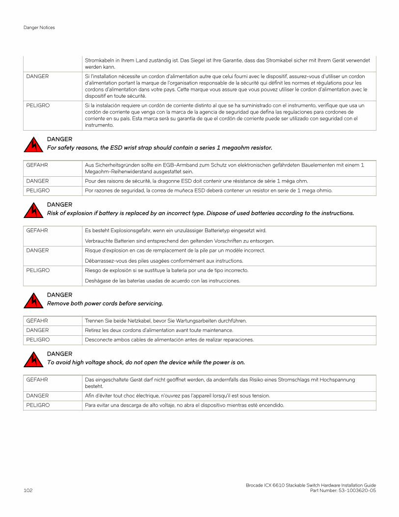
Stromkabeln in Ihrem Land zuständig ist. Das Siegel ist Ihre Garantie, dass das Stromkabel sicher mit Ihrem Gerät verwendetwerden kann.
DANGER Si l'installation nécessite un cordon d'alimentation autre que celui fourni avec le dispositif, assurez-vous d'utiliser un cordond'alimentation portant la marque de l'organisation responsable de la sécurité qui définit les normes et régulations pour lescordons d'alimentation dans votre pays. Cette marque vous assure que vous pouvez utiliser le cordon d'alimentation avec ledispositif en toute sécurité.
PELIGRO Si la instalación requiere un cordón de corriente distinto al que se ha suministrado con el instrumento, verifique que usa uncordón de corriente que venga con la marca de la agencia de seguridad que defina las regulaciones para cordones decorriente en su país. Esta marca será su garantía de que el cordón de corriente puede ser utilizado con seguridad con elinstrumento.
DANGERFor safety reasons, the ESD wrist strap should contain a series 1 megaohm resistor.
GEFAHR Aus Sicherheitsgründen sollte ein EGB-Armband zum Schutz von elektronischen gefährdeten Bauelementen mit einem 1Megaohm-Reihenwiderstand ausgestattet sein.
DANGER Pour des raisons de sécurité, la dragonne ESD doit contenir une résistance de série 1 méga ohm.
PELIGRO Por razones de seguridad, la correa de muñeca ESD deberá contener un resistor en serie de 1 mega ohmio.
DANGERRisk of explosion if battery is replaced by an incorrect type. Dispose of used batteries according to the instructions.
GEFAHR Es besteht Explosionsgefahr, wenn ein unzulässiger Batterietyp eingesetzt wird.
Verbrauchte Batterien sind entsprechend den geltenden Vorschriften zu entsorgen.
DANGER Risque d'explosion en cas de remplacement de la pile par un modèle incorrect.
Débarrassez-vous des piles usagées conformément aux instructions.
PELIGRO Riesgo de explosión si se sustituye la batería por una de tipo incorrecto.
Deshágase de las baterías usadas de acuerdo con las instrucciones.
DANGERRemove both power cords before servicing.
GEFAHR Trennen Sie beide Netzkabel, bevor Sie Wartungsarbeiten durchführen.
DANGER Retirez les deux cordons d'alimentation avant toute maintenance.
PELIGRO Desconecte ambos cables de alimentación antes de realizar reparaciones.
DANGERTo avoid high voltage shock, do not open the device while the power is on.
GEFAHR Das eingeschaltete Gerät darf nicht geöffnet werden, da andernfalls das Risiko eines Stromschlags mit Hochspannungbesteht.
DANGER Afin d'éviter tout choc électrique, n'ouvrez pas l'appareil lorsqu'il est sous tension.
PELIGRO Para evitar una descarga de alto voltaje, no abra el dispositivo mientras esté encendido.
Danger Notices
Brocade ICX 6610 Stackable Switch Hardware Installation Guide102 Part Number: 53-1003620-05
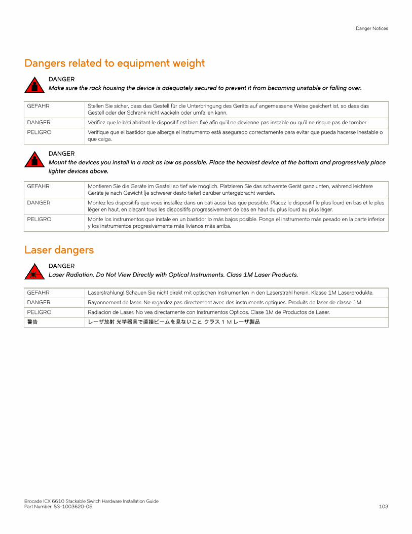
Dangers related to equipment weightDANGERMake sure the rack housing the device is adequately secured to prevent it from becoming unstable or falling over.
GEFAHR Stellen Sie sicher, dass das Gestell für die Unterbringung des Geräts auf angemessene Weise gesichert ist, so dass dasGestell oder der Schrank nicht wackeln oder umfallen kann.
DANGER Vérifiez que le bâti abritant le dispositif est bien fixé afin qu'il ne devienne pas instable ou qu'il ne risque pas de tomber.
PELIGRO Verifique que el bastidor que alberga el instrumento está asegurado correctamente para evitar que pueda hacerse inestable oque caiga.
DANGERMount the devices you install in a rack as low as possible. Place the heaviest device at the bottom and progressively placelighter devices above.
GEFAHR Montieren Sie die Geräte im Gestell so tief wie möglich. Platzieren Sie das schwerste Gerät ganz unten, während leichtereGeräte je nach Gewicht (je schwerer desto tiefer) darüber untergebracht werden.
DANGER Montez les dispositifs que vous installez dans un bâti aussi bas que possible. Placez le dispositif le plus lourd en bas et le plusléger en haut, en plaçant tous les dispositifs progressivement de bas en haut du plus lourd au plus léger.
PELIGRO Monte los instrumentos que instale en un bastidor lo más bajos posible. Ponga el instrumento más pesado en la parte inferiory los instrumentos progresivamente más livianos más arriba.
Laser dangersDANGERLaser Radiation. Do Not View Directly with Optical Instruments. Class 1M Laser Products.
GEFAHR Laserstrahlung! Schauen Sie nicht direkt mit optischen Instrumenten in den Laserstrahl herein. Klasse 1M Laserprodukte.
DANGER Rayonnement de laser. Ne regardez pas directement avec des instruments optiques. Produits de laser de classe 1M.
PELIGRO Radiacion de Laser. No vea directamente con Instrumentos Opticos. Clase 1M de Productos de Laser.
警告 レーザ放射 光学器具で直接ビームを見ないこと クラス1 M レーザ製品
Danger Notices
Brocade ICX 6610 Stackable Switch Hardware Installation GuidePart Number: 53-1003620-05 103