Embed Size (px)
Citation preview

53-1002449-0608 May 2015
Brocade 6505Hardware Installation Guide

© 2015, Brocade Communications Systems, Inc. All Rights Reserved.
ADX, Brocade, Brocade Assurance, the B-wing symbol, DCX, Fabric OS, HyperEdge, ICX, MLX, MyBrocade, OpenScript, The EffortlessNetwork, VCS, VDX, Vplane, and Vyatta are registered trademarks, and Fabric Vision and vADX are trademarks of BrocadeCommunications Systems, Inc., in the United States and/or in other countries. Other brands, products, or service names mentioned may betrademarks of others.
Notice: This document is for informational purposes only and does not set forth any warranty, expressed or implied, concerning anyequipment, equipment feature, or service offered or to be offered by Brocade. Brocade reserves the right to make changes to this documentat any time, without notice, and assumes no responsibility for its use. This informational document describes features that may not becurrently available. Contact a Brocade sales office for information on feature and product availability. Export of technical data contained inthis document may require an export license from the United States government.
The authors and Brocade Communications Systems, Inc. assume no liability or responsibility to any person or entity with respect to theaccuracy of this document or any loss, cost, liability, or damages arising from the information contained herein or the computer programs thataccompany it.
The product described by this document may contain open source software covered by the GNU General Public License or other opensource license agreements. To find out which open source software is included in Brocade products, view the licensing terms applicable tothe open source software, and obtain a copy of the programming source code, please visit http://www.brocade.com/support/oscd.

Contents
Preface..................................................................................................................................... 5Document conventions......................................................................................5
Text formatting conventions.................................................................. 5Command syntax conventions.............................................................. 5Notes, cautions, and warnings.............................................................. 6
Brocade resources............................................................................................ 7Contacting Brocade Technical Support.............................................................7Document feedback.......................................................................................... 8
About This Document................................................................................................................ 9Supported hardware and software.................................................................... 9What’s new in this document............................................................................ 9
Brocade 6505 Introduction.....................................................................................................11Brocade 6505 overview...................................................................................11
Platform features.................................................................................11Platform components.......................................................................... 12
Facility requirements....................................................................................... 13Port side of the Brocade 6505.........................................................................13Nonport side of the Brocade 6505.................................................................. 14
Brocade 6505 Installation and Configuration.......................................................................... 15Items included with the Brocade 6505............................................................ 15Installation and safety considerations............................................................. 15
Installation precautions....................................................................... 15ESD precautions................................................................................. 16Power precautions.............................................................................. 16RTC battery.........................................................................................17Environmental considerations............................................................. 17EIA rack installation considerations.................................................... 17Recommendations for cable management......................................... 18Items required for installation.............................................................. 18
Standalone installation for a Brocade 6505.................................................... 19Rack installation for a Brocade 6505.............................................................. 19Brocade 6505 configuration............................................................................ 19
Providing power to the switch............................................................. 19Creating a serial connection................................................................20Switch IP address............................................................................... 20Date and time settings........................................................................ 21Brocade Inter-Switch Link trunking..................................................... 24Brocade switchstatus policy................................................................ 24
Fabric OS Native and Access Gateway modes.............................................. 25Access Gateway default port mapping................................................25Disabling and enabling Access Gateway mode.................................. 26
Brocade 6505 Operation........................................................................................................ 29
Brocade 6505 Hardware Installation Guide 353-1002449-06

Powering the Brocade 6505 on and off.........................................................29LED activity interpretation............................................................................. 29
Brocade 6505 LEDs..........................................................................30LED locations....................................................................................30LED patterns..................................................................................... 31
POST and boot specifications.......................................................................33POST................................................................................................ 33Boot...................................................................................................33
Interpreting POST results..............................................................................34Brocade 6505 maintenance.......................................................................... 34
Installing an SFP+ transceiver.......................................................... 34Brocade 6505 management..........................................................................36
Removal and Replacement of Power Supplies and Fans.........................................................39Power supply and fan assembly information................................................ 39Removing and replacing a power supply and fan assembly.........................40
Determining the need to replace a power supply and fanassembly..................................................................................... 41
Time and items required................................................................... 41Removing a power supply and fan assembly................................... 42Replacing a power supply and fan assembly....................................43
Adding a second power supply and fan assembly in a Brocade 6505..........43Time and items required................................................................... 43Installing a second power supply and fan assembly.........................44
Brocade 6505 Switch Technical Specifications..................................................................... 45
Regulatory Statements..........................................................................................................51BSMI statement (Taiwan)..............................................................................51Canadian requirements.................................................................................51CE Statement................................................................................................51China CC statement......................................................................................52China ROHS................................................................................................. 53FCC warning (US only)................................................................................. 53Germany....................................................................................................... 53KCC statement (Republic of Korea)..............................................................53VCCI statement.............................................................................................53
Cautions and Danger Notices................................................................................................ 55Cautions........................................................................................................55Danger Notices............................................................................................. 58
4 Brocade 6505 Hardware Installation Guide53-1002449-06

Preface
● Document conventions......................................................................................................5● Brocade resources............................................................................................................ 7● Contacting Brocade Technical Support.............................................................................7● Document feedback.......................................................................................................... 8
Document conventionsThe document conventions describe text formatting conventions, command syntax conventions, andimportant notice formats used in Brocade technical documentation.
Text formatting conventionsText formatting conventions such as boldface, italic, or Courier font may be used in the flow of the textto highlight specific words or phrases.
Format Description
bold text Identifies command names
Identifies keywords and operands
Identifies the names of user-manipulated GUI elements
Identifies text to enter at the GUI
italic text Identifies emphasis
Identifies variables
Identifies document titles
Courier font Identifies CLI output
Identifies command syntax examples
Command syntax conventionsBold and italic text identify command syntax components. Delimiters and operators define groupings ofparameters and their logical relationships.
Convention Description
bold text Identifies command names, keywords, and command options.
italic text Identifies a variable.
value In Fibre Channel products, a fixed value provided as input to a commandoption is printed in plain text, for example, --show WWN.
Brocade 6505 Hardware Installation Guide 553-1002449-06

Convention Description
[ ] Syntax components displayed within square brackets are optional.
Default responses to system prompts are enclosed in square brackets.
{ x | y | z } A choice of required parameters is enclosed in curly brackets separated byvertical bars. You must select one of the options.
In Fibre Channel products, square brackets may be used instead for thispurpose.
x | y A vertical bar separates mutually exclusive elements.
< > Nonprinting characters, for example, passwords, are enclosed in anglebrackets.
... Repeat the previous element, for example, member[member...].
\ Indicates a “soft” line break in command examples. If a backslash separatestwo lines of a command input, enter the entire command at the prompt withoutthe backslash.
Notes, cautions, and warningsNotes, cautions, and warning statements may be used in this document. They are listed in the order ofincreasing severity of potential hazards.
NOTEA Note provides a tip, guidance, or advice, emphasizes important information, or provides a referenceto related information.
ATTENTIONAn Attention statement indicates a stronger note, for example, to alert you when traffic might beinterrupted or the device might reboot.
CAUTIONA Caution statement alerts you to situations that can be potentially hazardous to you or causedamage to hardware, firmware, software, or data.
DANGERA Danger statement indicates conditions or situations that can be potentially lethal orextremely hazardous to you. Safety labels are also attached directly to products to warn ofthese conditions or situations.
Notes, cautions, and warnings
6 Brocade 6505 Hardware Installation Guide53-1002449-06

Brocade resourcesVisit the Brocade website to locate related documentation for your product and additional Brocaderesources.
You can download additional publications supporting your product at www.brocade.com. Select theBrocade Products tab to locate your product, then click the Brocade product name or image to open theindividual product page. The user manuals are available in the resources module at the bottom of thepage under the Documentation category.
To get up-to-the-minute information on Brocade products and resources, go to MyBrocade. You canregister at no cost to obtain a user ID and password.
Release notes are available on MyBrocade under Product Downloads.
White papers, online demonstrations, and data sheets are available through the Brocade website.
Contacting Brocade Technical SupportAs a Brocade customer, you can contact Brocade Technical Support 24x7 online, by telephone, or by e-mail. Brocade OEM customers contact their OEM/Solutions provider.
Brocade customersFor product support information and the latest information on contacting the Technical AssistanceCenter, go to http://www.brocade.com/services-support/index.html.
If you have purchased Brocade product support directly from Brocade, use one of the following methodsto contact the Brocade Technical Assistance Center 24x7.
Online Telephone E-mail
Preferred method of contact for non-urgent issues:
• My Cases through MyBrocade• Software downloads and licensing
tools• Knowledge Base
Required for Sev 1-Critical and Sev2-High issues:
• Continental US: 1-800-752-8061• Europe, Middle East, Africa, and
Asia Pacific: +800-AT FIBREE(+800 28 34 27 33)
• For areas unable to access tollfree number: +1-408-333-6061
• Toll-free numbers are available inmany countries.
Please include:
• Problem summary• Serial number• Installation details• Environment description
Brocade OEM customersIf you have purchased Brocade product support from a Brocade OEM/Solution Provider, contact yourOEM/Solution Provider for all of your product support needs.
• OEM/Solution Providers are trained and certified by Brocade to support Brocade® products.• Brocade provides backline support for issues that cannot be resolved by the OEM/Solution Provider.
Brocade resources
Brocade 6505 Hardware Installation Guide 753-1002449-06

• Brocade Supplemental Support augments your existing OEM support contract, providing directaccess to Brocade expertise. For more information, contact Brocade or your OEM.
• For questions regarding service levels and response times, contact your OEM/Solution Provider.
Document feedbackTo send feedback and report errors in the documentation you can use the feedback form posted withthe document or you can e-mail the documentation team.
Quality is our first concern at Brocade and we have made every effort to ensure the accuracy andcompleteness of this document. However, if you find an error or an omission, or you think that a topicneeds further development, we want to hear from you. You can provide feedback in two ways:
• Through the online feedback form in the HTML documents posted on www.brocade.com.• By sending your feedback to [email protected].
Provide the publication title, part number, and as much detail as possible, including the topic headingand page number if applicable, as well as your suggestions for improvement.
Document feedback
8 Brocade 6505 Hardware Installation Guide53-1002449-06

About This Document
● Supported hardware and software.................................................................................... 9● What’s new in this document............................................................................................ 9
Supported hardware and softwareThis document includes information specific to the Brocade 6520 running Brocade Fabric OS version7.1.0. and later.
What’s new in this documentThe following changes have been made:
• An illustration indicating the port numbers and the port groups is added.• FL_Port type is removed since FL_Port type is not supported.• All references to EIA cabinet have been changed to EIA rack since enclosed cabinets are not
supported by Brocade products.• The regulatory compliance statements are moved to a new chapter/appendix.
‐ China CCC certification has been updated from “GB17625.1-2003 or latest” to“GB17625.1-2012 or latest”.
‐ Laser compliance statement is removed.‐ The Japan VCCI statement has been updated.‐ China RoHS compliance statements are removed and a reference to the latest independent
China RoHS compliance document is added.• A new chapter/appendix on cautions and danger notices is added with translation in multiple
languages.
Brocade 6505 Hardware Installation Guide 953-1002449-06

What’s new in this document
10 Brocade 6505 Hardware Installation Guide53-1002449-06

Brocade 6505 Introduction
● Brocade 6505 overview...................................................................................................11● Facility requirements....................................................................................................... 13● Port side of the Brocade 6505.........................................................................................13● Nonport side of the Brocade 6505.................................................................................. 14
Brocade 6505 overviewThe Brocade 6505 is a 24-port auto-sensing 2, 4, 8, or 16 Gbps Fibre Channel (FC) switch that deliversthe latest Brocade single-chip architecture for Fibre Channel Storage Area Networks (SANs). TheBrocade 6505 is a small-to-midsize business-class switch that is designed to handle smaller-scale SANrequirements.
The Brocade 6505 provides up to 24 ports in a single height (1U) switch that enables the creation ofvery dense fabrics in a relatively small space.
The Brocade 6505 offers Ports on Demand (POD) licensing as well. "Base" models of the switchcontain 12 ports, and an additional 12-port POD license can be purchased. The base model also offersa single power supply and fan module with a second module available as an upgrade for redundancy.
The Brocade 6505 supplies Reliability, Availability, and Serviceability (RAS) performance and thescalability requirements of an enterprise switch along with interoperability and ease-of-use advantages.
The Brocade 6505 can also be configured in Access Gateway (AG) mode that lets you configure yourEnterprise fabric to handle additional N_Ports instead of domains. By reducing the number of domainIDs and ports, you simplify configuration and management in a large fabric.
Switches in AG mode are logically transparent to the host and the fabric. You can increase the numberof hosts that have access to the fabric without increasing the number of switches.
Platform featuresThe Brocade 6505 offers the following features and capabilities:
• Up to 24 auto-sensing ports of high-performance 16-Gbps technology in a single domain.• Ports on Demand scaling from 12 to 24 ports.• 2, 4, 8, and 16 Gbps auto-sensing Fibre Channel switch and router ports.
‐ 2, 4, and 8 Gbps performance is enabled by 8 Gbps SFP+ transceivers.‐ 4, 8, and 16 Gbps performance is enabled by 16 Gbps SFP+ transceivers.
• Universal ports self-configure as E, F, or M ports. D-port functionality is also available for diagnostics.• Airflow is set for port side exhaust.• Inter-Switch Link (ISL) Trunking, which allows up to eight ports (at 2, 4, 8, or 16 Gbps speeds)
between a pair of switches combined to form a single, logical ISL with a speed of up to 128 Gbps(256 Gbps full duplex) for optimal bandwidth utilization and load balancing. The base model permitsone eight-port trunk plus one four-port trunk.
• Dynamic Path Selection (DPS), which optimizes fabric-wide performance and load balancing byautomatically routing data to the most efficient available path in the fabric.
Brocade 6505 Hardware Installation Guide 1153-1002449-06

• Brocade-branded SFP+ optical transceivers that support any combination of Short Wavelength(SWL), Long Wavelength (LWL), and Extended Long Wavelength (ELWL) optical media among theswitch ports.
• Extended distance support enables native Fibre Channel extension up to 7,500 km at 2 Gbps.• Support for unicast traffic type.• Brocade Fabric OS, which delivers distributed intelligence throughout the network and enables a
wide range of value-added applications including Brocade Advanced Web Tools, BrocadeEnhanced Group Management, and Brocade Zoning.
• Licensable fabric services include:
‐ Adaptive Networking with QoS‐ Brocade Extended Fabrics‐ Brocade Fabric Watch‐ ISL Trunking‐ Advanced Performance Monitoring (APM)‐ Server Application Optimization (SAO)
• Support for Access Gateway configuration where server ports connected to the fabric core will bevirtualized.
• Hardware zoning is accomplished at the port level of the switch and by World Wide Name (WWN).Hardware zoning permits or denies delivery of frames to any destination port address.
• Extensive diagnostics and system-monitoring capabilities for enhanced high Reliability, Availability,and Serviceability (RAS).
• The Brocade EZSwitchSetup wizard that makes SAN configuration a three-step point-and-clicktask.
• Real-time power monitoring enables users to monitor real-time power usage of the fabric at a switchlevel.
• Port-to-port latency minimized to 800 nanoseconds through the use of cut-through frame routing at16 Gbps.
Platform components• A system motherboard that features a PowerPC 440EPx Reduced Instruction Set Computer (RISC)
CPU running at 667 MHz, with integrated peripherals.• An RJ45 10/100 BaseT Ethernet system management port, in conjunction with Brocade
EZSwitchSetup, that supports switch IP address discovery and configuration, eliminating the needto attach a serial cable to configure the switch IP address and greatly increasing the ease of use.
• One RS-232 serial port with an RJ45 connector for initial switch setup (if not using EZSwitchSetup)and factory default restoration.
• A USB 2.0 port that provides storage for firmware updates, output of the supportSave command,and storage for configuration uploads and downloads.
• One power supply and fan assembly in the base model. There are two fans per assembly. A secondassembly is available for redundancy and hot-swap capability.
• One LED (green/amber) per FC port to indicate status.• One LED (green) for system power.• One LED (green/amber) for system status.• Two Ethernet port LEDs (integrated with RJ45) for speed and port activity. (A green LED for port
speed and an amber LED for port activity.)• SEEPROM for switch identification.• Voltage monitor.• Fan monitor.• Temperature monitor.• Real-time clock (RTC) with battery.
Platform components
12 Brocade 6505 Hardware Installation Guide53-1002449-06

Facility requirements
The following table provides the facilities requirements that must be met for the Brocade 6505.
Facility requirements TABLE 1
Type Requirements
Electrical • Adequate supply circuit, line fusing, and wire size, as specified by the electrical rating on theswitch nameplate.
• Circuit protected by a circuit breaker and grounded in accordance with local electrical codes.
Refer to Brocade 6505 Technical Specification on page 0 for complete power supplyspecifications.
Thermal • A minimum airflow of 79.8 cubic meters/hour (47 cubic ft/min.) available in the immediatevicinity of the switch.
• Ambient air temperature not exceeding 40 ° C (104 ° F) while the switch is operating.
Rack (when rack-mounted)
• One rack unit (1U) in a 48.3 cm (19-inch) rack.• All equipment in rack grounded through a reliable branch circuit connection.• Additional weight of switch not to exceed the rack’s weight limits.• Rack secured to ensure stability in case of unexpected movement.
Port side of the Brocade 6505The port side of the Brocade 6505 includes the system status LED, the console port, the Ethernet portand accompanying LEDs, the USB port, and the Fibre Channel ports and corresponding port statusLEDs.
FIGURE 1 Port side of the Brocade 6505
1. System status LED2. Management Ethernet port with LEDs3. USB port4. FC ports 0-3 (all LEDs above)5. System power LED6. Serial console port
Facility requirements
Brocade 6505 Hardware Installation Guide 1353-1002449-06

7. Switch ID pull-out tab8. FC ports 4-7
NOTEThe two LEDs on the serial console port are non-functional.
FIGURE 2 Trunking port groups and port numbers of the Brocade 6505
1. Trunking port group 1: FC ports 00-072. Trunking port group 2: FC ports 08-153. Trunking port group 3: FC ports 16-23
NOTEYou can also use port index and PIDs to identify a port. For more information, refer to the Fabric OSAdministrator's Guide.
Nonport side of the Brocade 6505The following figure shows the non-port side of the Brocade 6505, which contains the power supply(including the AC power receptacle and AC power switch) and fan assemblies. The base modelconfiguration with a single assembly is shown.
FIGURE 3 Nonport side of the Brocade 6505
1. Filler panel2. Power supply and fan assembly #13. Power supply and fan assembly LED4. On/off switch5. Power plug receptacle (with plug retainer)6. Captive screw7. Handle
Nonport side of the Brocade 6505
14 Brocade 6505 Hardware Installation Guide53-1002449-06

Brocade 6505 Installation and Configuration
● Items included with the Brocade 6505............................................................................ 15● Installation and safety considerations............................................................................. 15● Standalone installation for a Brocade 6505.................................................................... 19● Rack installation for a Brocade 6505.............................................................................. 19● Brocade 6505 configuration............................................................................................ 19● Fabric OS Native and Access Gateway modes.............................................................. 25
Items included with the Brocade 6505The following items are included with the standard shipment of a fully-configured Brocade 6505. Whenyou open the Brocade 6505 packaging, verify that these items are included in the package and that nodamage has occurred during shipping:
• The Brocade 6505 switch, containing one combined power supply and fan assembly• 16 Gbps or 8 Gbps SFP+ modules for the Fibre Channel ports (speed and quantity as ordered)• One accessory kit, containing the following items:
‐ Serial cable with an RJ45 connector‐ RJ45-to-DB9 adapter‐ One 6 foot power cord‐ Rubber feet, required for setting up the switch as a standalone unit‐ Brocade 6505 EZSwitchSetup poster‐ EZSwitchSetup CD
Installation and safety considerationsYou can install the Brocade 6505 switch in the following ways:
• As a standalone unit on a flat surface.• In an EIA rack using a slim rail rack mount kit. The rack mount kit can be ordered from your switch
retailer.• In an EIA rack using an optional mid-mount rack kit for switches. The optional mid-mount rack kit for
switches can be ordered from your switch retailer.
Installation precautionsWhen using this product, observe all danger, caution, and attention notices in this manual. The noticesare accompanied by symbols that represent the severity of the safety condition.
NOTERefer to Cautions and Danger Notices on page 55 for translations of safety notices for this product.
Brocade 6505 Hardware Installation Guide 1553-1002449-06

ESD precautionsThe Brocade 6505contains electrostatic discharge (ESD) sensitive FRUs. When working with anyBrocade 6505 FRU, use correct ESD procedures.
CAUTIONBefore plugging a cable into to any port, be sure to discharge the voltage stored on the cableby touching the electrical contacts to ground surface.
CAUTIONStatic electricity can damage the chassis and other electronic devices. To avoid damage, keepstatic-sensitive devices in their static-protective packages until you are ready to install them.
Wear a wrist grounding strap connected to chassis ground (if the Brocade 6505 is plugged in) or abench ground.
DANGERFor safety reasons, the ESD wrist strap should contain a series 1 megaohm resistor.
Power precautionsTo install and operate the switch successfully, ensure the following:
• The primary outlet is correctly wired, protected by a circuit breaker, and grounded in accordancewith local electrical codes.
• Connect the power cord only to a grounded outlet.
DANGERMake sure that the power source circuits are properly grounded, then use the power cordsupplied with the device to connect it to the power source.
• The supply circuit, line fusing, and wire size are adequate, as specified by the electrical rating onthe switch nameplate.
• This switch might have more than one power cord. To reduce the risk of electric shock, disconnectboth power cords before servicing.
DANGERRemove both power cords before servicing.
DANGERDisconnect the power cord from all power sources to completely remove power from thedevice.
• This product is designed for an IT power system with phase-to-phase voltage of 230V. Afteroperation of the protective device, the equipment is still under voltage if it is connected to an ITpower system.
DANGERTo avoid high voltage shock, do not open the device while the power is on.
• The power supply standards provided in Brocade 6505 Technical Specification on page 0 aremet.
ESD precautions
16 Brocade 6505 Hardware Installation Guide53-1002449-06

RTC batteryDo not attempt to replace the real-time clock (RTC) battery. There is a danger of explosion if the batteryis incorrectly replaced or disposed of. Contact your switch supplier if the real-time clock begins to losetime.
DANGERRisk of explosion if battery is replaced by an incorrect type. Dispose of used batteries accordingto the instructions.
Environmental considerationsFor successful installation and operation of the switch, ensure that the following environmentalrequirements are met:
• At a minimum, adequate cooling requires that you install the switch with the intake side, as indicatedby the airflow direction of the fan assemblies, facing the cool-air aisle.
• All equipment in the rack should force air in the same direction to avoid intake of exhaust air.
CAUTIONEnsure that the airflow direction of the power supply unit matches that of the installed fantray. The power supplies and fan trays are clearly labeled with either a green arrow with an"E", or an orange arrow with an "I."
• A maximum of 102 cubic meters/hour (60 cubic feet/minute) and a minimum of 74.8 cubic meters/hour (44 cubic feet/minute) of air flow is available for air intake.
CAUTIONMake sure the airflow around the front, sides, and back of the device is not restricted.
• Ensure temperature requirements are met.
CAUTIONDo not install the device in an environment where the operating ambient temperature mightexceed 40°C (104°F).
EIA rack installation considerationsFor successful installation and operation of the switch in an EIA rack, ensure the following requirementsare met:
• The rack must be a standard EIA rack.• A rack space that is at least one rack unit (1U) high; 4.45 cm (1.75 inches) high and 48.3 cm (19
inches) wide.• The two rack kit options for the Brocade 6505 use rails that are slimmer than standard rails to
accommodate the slightly wider chassis. Be sure to use one of these kits. Do not use standard railsto install the in a rack; they will not fit with the switch.
• The equipment in the rack is grounded through a reliable branch circuit connection and maintainsground at all times. Do not rely on a secondary connection to a branch circuit, such as a power strip.
• Airflow and temperature requirements are met on an ongoing basis, particularly if the switch isinstalled in a closed or multi-rack assembly.
RTC battery
Brocade 6505 Hardware Installation Guide 1753-1002449-06

• The additional weight of the switch does not exceed the rack’s weight limits or unbalance the rack inany way.
• The rack is secured to ensure stability in case of unexpected movement, such as an earthquake.
DANGERMake sure the rack housing the device is adequately secured to prevent it from becomingunstable or falling over.
Recommendations for cable managementThe minimum radius to which a 50 micron cable can be bent under full tensile load is 5.1 cm (2 in.).For a cable under no tensile load, that minimum is 3.0 cm (1.2 in.).
Cables can be organized and managed in a variety of ways, for example, using cable channels on thesides of the rack or patch panels to minimize cable management. Following is a list ofrecommendations:
NOTEYou should not use tie wraps with optical cables because they are easily overtightened and candamage the optic fibers.
CAUTIONBefore plugging a cable into to any port, be sure to discharge the voltage stored on the cableby touching the electrical contacts to ground surface.
• Plan for rack space required for cable management before installing the switch.• Leave at least 1 m (3.28 ft) of slack for each port cable. This provides room to remove and replace
the switch, allows for inadvertent movement of the rack, and helps prevent the cables from beingbent to less than the minimum bend radius.
• If you are using Brocade ISL Trunking, consider grouping cables by trunking groups. The cablesused in trunking groups must meet specific requirements, as described in the Fabric OSAdministrator’s Guide .
• For easier maintenance, label the fiber-optic cables and record the devices to which they areconnected.
• Keep LEDs visible by routing port cables and other cables away from the LEDs.• Use Velcro ® type straps to secure and organize fiber-optic cables.
Items required for installationThe following items are required for installing, configuring, and connecting the Brocade 6505 for use ina network and fabric:
• A workstation with an installed terminal emulator, such as HyperTerminal• An unused IP address and corresponding subnet mask and gateway address• A serial cable (provided) if not using EZSwitchSetup• An Ethernet cable• Brocade-branded SFP+ optical transcceivers and compatible cables (Brocade-branded 16 Gbps
SFP+ optical transcceivers required for 16 Gbps performance), as required• Access to an FTP server or USB device for backing up the switch configuration (optional)
Recommendations for cable management
18 Brocade 6505 Hardware Installation Guide53-1002449-06

Standalone installation for a Brocade 6505
Complete the following steps to install the Brocade 6505 as a standalone unit.
1. Unpack the Brocade 6505 and verify the items listed in Items included with the Brocade 6505 onpage 15. Verify the items are present and undamaged.
2. Apply the adhesive rubber feet. Applying the rubber feet onto the switch helps prevent the switchfrom sliding off the supporting surface.a) Clean the indentations at each corner of the bottom of the switch to ensure that they are
free of dust or other debris that might lessen the adhesion of the feet.b) With the adhesive side against the chassis, place one rubber foot in each indentation and
press into place.3. Place the switch on a flat, sturdy surface.4. Provide power to the switch as described in Providing power to the switch on page 19.
ATTENTION
Do not connect the switch to the network until the IP address is correctly set. For instructions on howto set the IP address, see Brocade 6505 configuration on page 19
Rack installation for a Brocade 6505Follow the installation instructions shipped with the appropriate rack mount kit:
• To install the switch into a fixed-rail rack, refer to the Slim Rail Rack Mount Kit InstallationProcedure .
• To install the switch into a 2-post Telco rack, refer to the Flush Mount Rack Mount Kit InstallationProcedure .
Brocade 6505 configurationOnce you have set up the Brocade 6505 in a rack or as a standalone switch, it is time to apply powerand a basic configuration. If you are going to use the Brocade 6505 in a single-switch setup, you canuse EZSwitchSetup to complete the basic configuration.
See the EZSwitchSetup CD, included with the Brocade 6505 EZSwitchSetup poster.
If you do not want to use EZSwitchSetup, continue with the instructions in this section.
Providing power to the switchPerform the following steps to provide power to the Brocade 6505.
1. Connect the power cord to the power supply, and then to a power source. If using two powersupplies, be sure to connect the cords to power sources on separate circuits to protect against AC
Standalone installation for a Brocade 6505
Brocade 6505 Hardware Installation Guide 1953-1002449-06

failure. Ensure that the cords have a minimum service loop of 6 inches available and are routed toavoid stress.
2. Power on the power supplies by flipping both AC switches to the "I" symbol. The power supplyLEDs display amber until power-on self-test (POST) is complete, and then change to green. Theswitch usually requires several minutes to boot and complete POST.
NOTE
Power is supplied to the switch as soon as the first power supply is connected and turned on.
3. After POST is complete, verify that the switch power and status LEDs on the left of the port side ofthe switch are green. See LED locations on page 30 for the specific location of the LEDs.
Creating a serial connection
NOTEYou will perform all configuration tasks in this guide using a serial connection.
Complete the following steps to create a serial connection to the switch.
1. Connect the serial cable to the serial port on the switch and to an RS-232 serial port on theworkstation.
If the serial port on the workstation is RJ45 instead of RS-232, remove the adapter on the end of theserial cable and insert the exposed RJ45 connector into the RJ45 serial port on the workstation.
2. Open a terminal emulator application (such as HyperTerminal on a PC, or TERM, TIP, or Kermit ina UNIX environment), and configure the application as follows:
• In a Windows environment, use 9600 bits per second, 8 databits, no parity, 1 stop bit, and noflow control.
• In a UNIX environment using TIP, enter the following string at the prompt:
tip /dev/ttyb -9600If ttyb is already in use, use ttya instead and enter the following string at the prompt:
tip /dev/ttya -9600
Switch IP addressYou can configure the Brocade 6505 with a static IP address, or you can use a Dynamic HostConfiguration Protocol (DHCP) server to set the IP address of the switch. DHCP is enabled by default.The Brocade 6505 supports both IPv4 and IPv6.
Using DHCP to set the IP address
When using DHCP, the Brocade 6505 obtains its IP address, subnet mask, and default gatewayaddress from the DHCP server. The DHCP client can only connect to a DHCP server that is on thesame subnet as the switch. If your DHCP server is not on the same subnet as the Brocade 6505, usea static IP address.
Creating a serial connection
20 Brocade 6505 Hardware Installation Guide53-1002449-06

Setting a static IP address
1. Log in to the switch using the default password (which is password).2. Use the ipaddrset command to set the Ethernet IP address.
If you are going to use an IPv4 IP address, enter the IP address in dotted decimal notation asprompted. As you enter a value and press Enter for a line in the following example, the next lineappears.
For instance, the Ethernet IP address appears first. When you enter a new IP address and pressEnter or simply press Enter to accept the existing value, the Ethernet Subnetmask line appears.
In addition to the Ethernet IP address itself, you can set the Ethernet subnet mask, the Gateway IPaddress, and whether to obtain the IP address by way of DHCP.
switch:admin> ipaddrsetEthernet IP Address [192.168.74.102]:Ethernet Subnetmask [255.255.255.0]:Gateway IP Address [192.168.74.1]:DHCP [Off]: offIf you are going to use an IPv6 address, enter the network information in semicolon-separatednotation as a standalone command.
switch:admin> ipaddrset -ipv6 --add 1080::8:800:200C:417A/64IP address is being changed...Done.
Date and time settingsThe Brocade 6505 maintains the current date and time inside a battery-backed real-time clock (RTC)circuit. Date and time are used for time stamping log events. Switch operation does not depend on thedate and time; a Brocade 6505 with an incorrect date and time value still functions properly. However,because the date and time are used for logging, error detection, and troubleshooting, you should setthem correctly.
Time zones
You can set the time zone for the switch by name. You can select continent, country, or time zoneregion names.
If the time zone is not set with the named options, the switch retains the offset time zone settings. Thisis a number of hours offset from Greenwich Mean Time (GMT). If you have set the time zone with aname, you can revert to the offset format if you choose. For more information about the tsTimeZonecommand, refer to the Fabric OS Command Reference.
You can set the time zone for a switch using the tsTimeZone command. The tsTimeZone commandallows you to perform the following tasks:
• Display all of the time zones supported in the firmware• Set the time zone based on a country and city combination or based on a time zone ID such as PST
The time zone setting has the following characteristics:
• You can view the time zone settings. However, only those with administrative permissions can setthe time zones.
• The tsTimeZone setting automatically adjusts for Daylight Savings Time.• Changing the time zone on a switch updates the local time zone setup and is reflected in local time
calculations.• By default, all switches are in the GMT time zone (0,0). If all switches in a fabric are in one time zone,
it is possible for you to keep the time zone setup at the default setting.
Setting a static IP address
Brocade 6505 Hardware Installation Guide 2153-1002449-06

• System services that have already started will reflect the time zone changes only after the nextreboot.
• Time zone settings persist across failover for high availability.
Local time synchronization
You can synchronize the local time of the principal or primary fabric configuration server (FCS) switchto a maximum of eight external Network Time Protocol (NTP) servers. To keep the time in your SANcurrent, it is recommended that the principal or primary FCS switch has its time synchronized with atleast one external NTP server. The other switches in the fabric will automatically take their time fromthe principal or primary FCS switch.
All switches in the fabric maintain the current clock server IP address in non-volatile memory. Bydefault, this value is LOCL, the local clock server of the Principal (when FCS not enabled) or Primary(when FCS is enabled) switch. Changes to the clock server value on the Principal or Primary switchare propagated to all switches in the fabric.
When a new switch enters the fabric, the time server daemon of the Principal or Primary switch sendsout the addresses of all existing clock servers and the time to the new switch. If a switch with FabricOS v5.3.0 or later has entered the fabric, it will be able to store the list of all the clock serveraddresses; switches running Fabric OS versions earlier than v5.3.0 will ignore the new list parameterin the payload and will update only the active server address.
If the active NTP server configured is IPv6, then distributing the IP address in the fabric will not bepossible to switches earlier than Fabric OS v5.3.0 because IPv6 is supported for Fabric OS v5.3.0 andlater. The default value LOCL will be distributed to switches earlier than Fabric OS v5.3.0.
The tsClockServer command accepts multiple server addresses in IPv4, IPv6, or DNS name formats.When multiple NTP server addresses are passed, tsClockServer sets the first obtainable address asthe active NTP server. The rest are stored as backup servers that can take over if the active NTPserver fails. The Principal or Primary switch synchronizes its time with the NTP server every 64seconds.
Setting the date
1. Log in to the switch using the default password (which is password).2. Enter the date command, using the following syntax:
date "mmddHHMMyy"The values are:
• mm is the month; valid values are 01 through 12.• dd is the date; valid values are 01 through 31.• HH is the hour; valid values are 00 through 23.• MM is minutes; valid values are 00 through 59.• yy is the year; valid values are 00 through 99 (values greater than 69 are interpreted as 1970
through 1999, and values less than 70 are interpreted as 2000 through 2069).
switch:admin> dateFri Sep 29 17:01:48 UTC 2007switch:admin> date "0927123007"Thu Sep 27 12:30:00 UTC 2007switch:admin>
Local time synchronization
22 Brocade 6505 Hardware Installation Guide53-1002449-06

Setting time zones
You must perform the procedure on all switches for which the time zone must be set. However, you onlyneed to set the time zone once on each switch, because the value is written to nonvolatile memory.
Use one of the two following procedures to set the time zone. The first procedure requires you to selectthe actual time zone and the second requires you to select the country location of the switch.
The following procedure describes how to set the current time zone to Central Standard time usingtimezonename mode.
1. Log in to the switch using the default password (which is password).2. Enter the tsTimeZone command as follows:
Use timezonename to set the time zone by time zone ID, such as PST or Country/City.
The following example shows how to change the time zone to US/Central. The tsTimeZonecommand by itself display the current time zone.
switch:admin> tstimezoneTime Zone : US/Pacificswitch:admin> tstimezone US/Centralswitch:admin> tstimezoneTime Zone : US/CentralThe following procedure describes how to set the current time zone to Pacific Standard Time usinginteractive mode.
1. Enter the tsTimeZone command as follows:
switch:admin> tstimezone --interactiveYou are prompted to select a general location from a list.
Please identify a location so that time zone rules can be set correctly.2. Enter the appropriate number from the list that appears or Ctrl‐D to quit.3. At the prompt, select a country location from the list.4. At the prompt, enter the appropriate number from the list to specify the time zone region or Ctrl‐D
to quit.
Synchronizing local time using NTP
Perform the following steps to synchronize the local time using NTP.
1. Log in to the switch using the default password(which is password).2. Enter the tsClockServer command:
switch:admin> tsclockserver "<ntp1;ntp2>"In the syntax ntp1 is the IP address or DNS name of the first NTP server, which the switch must beable to access. The value ntp2 is the name of the second NTP server and is optional. The entireoperand "<ntp1;ntp2>" is optional; by default, this value is LOCL, which uses the local clock of theprincipal or primary switch as the clock server.
switch:admin> tsclockserverLOCLswitch:admin> tsclockserver "132.163.135.131" switch:admin> tsclockserver132.163.135.131switch:admin>
Setting time zones
Brocade 6505 Hardware Installation Guide 2353-1002449-06

The following example shows how to set up more than one NTP server using a DNS name:
switch:admin> tsclockserver "10.32.170.1;10.32.170.2;ntp.localdomain.net"Updating Clock Server configuration...done.Updated with the NTP serversChanges to the clock server value on the principal or primary FCS switch are propagated to allswitches in the fabric.
Brocade Inter-Switch Link trunkingBrocade Inter-Switch Link (ISL) Trunking is optional software that allows you to create trunking groupsof ISLs between adjacent switches. Up to eight ports within a port group on the Brocade 6505 can beused as a trunking group to achieve speeds up to 128 Gbps (256 Gbps full duplex) for optimalbandwidth utilization and load balancing.
FIGURE 4 Port groups of the Brocade 6505
1. FC ports 0-72. FC ports 8-153. FC ports 16-23
For more information about Brocade ISL Trunking, see the Fabric OS Administrator's Guide.
Brocade switchstatus policyBrocade switchstatus policy is a feature that monitors different switch parameters such as powersupplies, fan units, and so forth and provides switch status based on their health.
The switchstatus policy configuration can be updated using the switchstatuspolicyset command.The example shows the default settings of 2 and 0 for DOWN and MARGINAL units for both BadPowerSupplies and Bad Fans.
switch:admin>switchstatuspolicyset<some output skipped>The minimum number ofBad PowerSupplies contributing to DOWN status: (0..2) [2]Bad PowerSupplies contributing to MARGINAL status: (0..2) [0]<some output skipped>Bad Fans contributing to DOWN status: (0..2) [2]Bad Fans contributing to MARGINAL status: (0..2) [0]<output truncated>
If a second power supply and fan assembly unit is installed in the switch, Brocade recommendschanging the configuration to 2 and 1 for DOWN and MARGINAL for both the Bad PowerSupplies andBad Fans. You can use the switchStatusPolicyShow command to see the results of your changes.
Brocade Inter-Switch Link trunking
24 Brocade 6505 Hardware Installation Guide53-1002449-06
Fabric OS Native and Access Gateway modesThe Brocade 6505 can function in either Fabric OS Native mode or Brocade Access Gateway mode.The switch is shipped in Fabric OS Native mode by default.
• You can enable Access Gateway mode using Fabric OS commands or Web Tools.• All additional POD licenses must be installed before you can enable Access Gateway mode.• When you enable Access Gateway, you can use the default F_Port-to-N_Port mappings or change
this mapping using the command line interface (CLI) or Web Tools (after you configure an IP addressusing instructions under Switch IP address on page 20).
• Access Gateway simplifies SAN deployment by using N_Port ID Virtualization (NPIV). NPIV providesFibre Channel switch functions that improve switch scalability, manageability, and interoperability.For more information on Access Gateway, refer to the following:
‐ For a list of F_Ports mapped to N_Ports by default, refer to Access Gateway default portmapping on page 25.
‐ For general information and details on using Access Gateway, refer to the Brocade AccessGateway Administrator’s Guide
‐ For specific instructions to prepare the edge fabric before connecting it to Access Gateway(because Access Gateway relies on NPIV technology for its connection to the edge fabric),refer to the Brocade Access Gateway Administrator’s Guide .
NOTEAccess Gateway cannot be connected directly into an array; it requires a fabric to support NPIV.
• Fabric OS features available to the Brocade 6505 depend on whether the switch is configured inAccess Gateway or Fabric OS Native mode. For a list of available features for each mode, refer tothe Brocade Access Gateway Administrator’s Guide
• In Access Gateway mode, cascading is not available for the Brocade 6505. Refer to the BrocadeAccess Gateway Administrator’s Guide for details on any other restrictions specific to the Brocade6505.
• In Fabric OS Native mode, the switch provides up to 24 external Fibre Channel ports. Theseuniversal and self-configuring ports are capable of becoming one of the following port types:
‐ F_Port (fabric enabled)‐ E_Port (expansion port)‐ M_Port (mirror port)‐ D_Port (diagnostic port)
• In Access Gateway mode, the switch provides up to 24 external Fibre Channel ports. However, theseports are configured as N_Ports, and you cannot reconfigure these as any other port type.
Access Gateway default port mappingThe following table lists the port mappings of F_Ports to N_Ports.
Fabric OS Native and Access Gateway modes
Brocade 6505 Hardware Installation Guide 2553-1002449-06

Access Gateway default port mappingTABLE 2
Total ports F_Ports N_Ports Default port mapping
24 0-15 16-23 • 0,1 mapped to 16• 2,3 mapped to 17• 4,5 mapped to 18• 6,7 mapped to 19• 8,9 mapped to 20• 10,11 mapped to 21• 12,13 mapped to 22• 14,15 mapped to 23
Disabling and enabling Access Gateway modeThis section provides steps to disable and enable Access Gateway mode using Fabric OS commands.For more information on using these commands, refer to the Brocade Access Gateway Administrator’sGuide or the Brocade Fabric OS Administrator’s Guide .
NOTEYou can also disable and enable Access Gateway mode using Web Tools. Refer to the Web ToolsAdministrator’s Guide for more information.
Enabling Access Gateway mode
Note the following when enabling Access Gateway mode:
• After you enable Access Gateway mode, some fabric information is erased, such as the zone andsecurity databases.
• Enabling Access Gateway mode is disruptive because the switch is disabled and rebooted.• Ensure that no zoning or Admin Domain (AD) transaction buffers are active. If any transaction buffer
is active, enabling Access Gateway mode will fail with the error, "Failed to clear Zoning/AdminDomain configuration."
Use the following steps to enable Access Gateway mode using Fabric OS commands.
1. Before disabling a switch to enable Access Gateway mode, save the current configuration file usingthe configupload command in case you might need this configuration again.
2. Enter the switchshow command to verify the switch mode.
• "Access Gateway Mode" displays for the switchMode value if the switch is in Access Gatewaymode.
• "Native" displays for the switchMode value if the switch is in Fabric OS Native mode.3. Enter switchDisable to disable the switch. Access Gateway mode can only be enabled or disabled
when the switch is in a disabled state.4. Enter ag -modeEnable to enable Access Gateway mode.5. Enter the ag --modeshow command to verify that Access Gateway mode is enabled.
switch:admin> ag --modeshowAccess Gateway mode is enabled.
Disabling and enabling Access Gateway mode
26 Brocade 6505 Hardware Installation Guide53-1002449-06

Disabling Access Gateway mode
When you disable Access Gateway mode, the switch automatically reboots and comes back onlineusing the fabric switch configuration. The Access Gateway parameters, such as F_Port-to-N_Portmapping, Failover, and Failback are automatically removed. When the switch reboots, it starts in FabricOS Native mode. To rejoin the switch to the core fabric, refer to the Brocade Access GatewayAdministrator’s Guide .
Use the following steps to disable Access Gateway mode using Fabric OS commands.
1. Enter the switchshow command to verify the switch mode.
• "Access Gateway Mode" displays if the switch is in Access Gateway mode.• "Native" displays if the switch is in Fabric OS Native mode.
2. Enter switchDisable to disable the switch. Access Gateway mode can only be disabled or enabledwhen the switch is in a disabled state.
3. Enter ag --modeDisable to disable Access Gateway mode.4. Enter the ag --modeshow command to verify that Access Gateway mode is disabled.
switch:admin> ag --modeshowAccess Gateway mode is NOT enabled
Disabling Access Gateway mode
Brocade 6505 Hardware Installation Guide 2753-1002449-06

Disabling Access Gateway mode
28 Brocade 6505 Hardware Installation Guide53-1002449-06

Brocade 6505 Operation
● Powering the Brocade 6505 on and off...........................................................................29● LED activity interpretation............................................................................................... 29● POST and boot specifications.........................................................................................33● Interpreting POST results................................................................................................34● Brocade 6505 maintenance............................................................................................ 34● Brocade 6505 management............................................................................................36
Powering the Brocade 6505 on and off
Complete the following steps to power on the Brocade 6505. These steps apply to the base model ofthe switch which has a single power supply.
1. Connect the power cord to the power connector on the power supply and fan assembly.2. Set the AC power switch to "I".
Power is supplied to the switch as soon as the power supply is connected and powered on.
The switch runs POST by default each time it is powered on; it can take up to several minutes to bootand complete POST.
Complete the following steps to power off the Brocade 6505.
1. Enter the sysShutDown command.
switch:admin> sysshutdownThis command will shutdown the operating systems on yourswitch. You are required to power‐cycle the switch inorder to restore operation.Are you sure you want to shutdown the switch [y/n]? yBroadcast message from root (ttyS0) Mon Sep 12 17: \52:12 2005...The system is going down for system halt NOW !!INIT: Switching to runlevel:INIT: Sending processes the TERM signalswitch:root> Unmounting all filesystems.The system is haltedflushing ide devices: hdaPower down.
2. Set the AC power switches to O.
All devices are returned to their initial state the next time the switch is powered on.
LED activity interpretationSystem activity and status can be determined through the activity of the LEDs on the switch.
There are three possible LED states: no light, a steady light, and a flashing light. Flashing LEDs may beslow, fast, or flickering. The LED colors are either green or amber.
Brocade 6505 Hardware Installation Guide 2953-1002449-06

Sometimes, the LEDs flash either of the colors during boot, POST, or other diagnostic tests. This isnormal; it does not indicate a problem unless the LEDs do not indicate a healthy state after all bootprocesses and diagnostic tests are complete.
Brocade 6505 LEDsThe Brocade 6505 has the following LEDs:
• One system status LED (upper) on the left side.• One power status LED (lower) on the left side.• Two Ethernet port LEDs (one amber, one green).• One bicolor (green and amber) port status LED for each port on the switch. These LEDs are
arrayed above each pair of Fibre Channel ports.• One power supply and fan assembly LED above the AC power switch on each power supply on the
non-port side of the switch.
LED locationsThe following figure shows the LEd locations on the port side of the Brocade 6505. The port statusLEDs for the FC ports are arranged left and right to correspond to the upper and lower portsrespectively in each pair. Refer to Port side of the Brocade 6505 on page 13 for the locations of the FCports.
FIGURE 5 LEDs on the port side of Brocade 6505
1. System power LED (green)2. System status LED green/amber)3. Ethernet port activity LED (amber)4. Ethernet port speed LED (green)5. FC port status LED (port 0)6. FC port status LED (port 4)7. FC port 08. FC port 4
Brocade 6505 LEDs
30 Brocade 6505 Hardware Installation Guide53-1002449-06

NOTEThe two LEDs on the serial console port are non-functional.
FIGURE 6 LEDs on the non-port side of Brocade 6505
1. Power supply and fan assembly #1 status LED
LED patternsThe following table describes the port side LEDs and their behavior.
Port side LED patterns during normal operation TABLE 3
LED name LED color Status of hardware Recommended action
Power Status
(green)
No light System is off or there is an internalpower supply failure.
Verify the system is powered on(power supply switches to I), thepower cables are attached, andyour power source is live.
Otherwise, contact your switchservice provider.
Steady green System is on and power suppliesare functioning properly.
No action required.
System Status
(bicolor)
No light System is off or there is no power. Verify the system is on and hascompleted booting.
Steady green System is on and functioningproperly.
No action required.
Steady amber(for more thanfive seconds)
A system fault has occurred.
This LED displays steady amberduring POST; this is normal anddoes not indicate a fault.
Check the failure indicated on thesystem console.
Contact your switch serviceprovider.
LED patterns
Brocade 6505 Hardware Installation Guide 3153-1002449-06

Port side LED patterns during normal operation (Continued)TABLE 3
LED name LED color Status of hardware Recommended action
Blinking amber Attention is required. A number offactors can cause this status,including;
• failure of a single power supplywhen two power supplies areinstalled
• fan failure• left FRU bay (#1) empty (when
looking at the port side of theswitch)
• one or more environmentalranges has been exceeded.
Check the management interfaceand the error log for details onthe cause of status.
Contact your switch serviceprovider.
Ethernet Speed (green) No light Port speed is 10 Mbps. No action required.
Steady green Port speed is 100 Mbps. No action required.
Ethernet Activity/Link(amber)
No light There is no link. Verify that the Ethernet cable isconnected correctly.
Steady amber There is a link. No action required.
Blinking amber There is link activity (traffic). No action required.
Optical media portstatus(one bicolor LEDfor each FC port)
Off No light or signal carrier on themedia interface.
Verify that the transceiver isinstalled correctly and that thecable is connected correctly.
Steady amber Receiving light or carrier, but notonline.
No action required.
Slow blinkingamber (2 sec)
Disabled (by diagnostics or byportDisable command).
Verify that the diagnostic testsare not being run. Re-enable theport using the portEnablecommand.
Fast blinkingamber (1/2 sec)
Port failure. Check the management interfaceand the error log for details onthe cause of the failure. ContactTechnical Support if necessary.
Steady green Online. No action required.
Slow blinkinggreen (2 sec)
Online but segmented (loopbackcable or incompatible switch).
No action required.
Fast blinkinggreen (1/2 sec)
Internal loopback (diagnostic). No action required.
Flickering green Online, frames flowing throughport.
No action required.
The following table describes the LEDs on the nonport side of the switch.
Brocade 6505 Operation
32 Brocade 6505 Hardware Installation Guide53-1002449-06

Nonport side LED patterns during normal operation TABLE 4
LED name LED color Status of hardware Recommended action
Power supply and fanassembly status(green)
No light Power supply and fan assembly isnot receiving power or is off.
Verify the power supply and fanassembly is on and seated and thepower cord is connected to afunctioning power source.
Steady green Power supply and fan assembly isoperating normally.
No action required.
Flashing green Power supply and fan assembly isfaulty.
Note: When the switch is firstpowered on the power supply andfan assembly status LED willshow flashing green until POSThas completed.
Check the power cable connection.
Verify that the power supply and fanassembly is powered on.
Replace the power supply and fanassembly FRU.
POST and boot specificationsWhen the switch is turned on or rebooted, the switch performs power-on self-test (POST). Total boottime with POST can be several minutes. POST can be omitted after subsequent reboots by using thefastboot command or entering the diagDisablePost command to persistently disable POST.
For more information about these commands, refer to the Fabric OS Command Reference Manual .
POSTThe success or failure results of the diagnostic tests that run during POST can be monitored throughLED activity, the error log, or the command line interface.
POST includes the following tasks:
• Conducts preliminary POST diagnostics.• Initializes the operating system.• Initializes hardware.• Runs diagnostic tests on several functions, including circuitry, port functionality, memory, statistics
counters, and serialization.
BootIn addition to POST, boot includes the following tasks after POST is complete:
• Performs universal port configuration.• Initializes links.• Analyzes fabric. If any ports are connected to other switches, the switch participates in a fabric
configuration.• Obtains a domain ID and assigns port addresses.• Constructs unicast routing tables.• Enables normal port operation.
POST and boot specifications
Brocade 6505 Hardware Installation Guide 3353-1002449-06

Interpreting POST results
POST is a system check that is performed each time the switch is powered on, rebooted, or reset.During POST, the LEDs flash either amber or green. Any errors that occur during POST are listed inthe error log.
Complete the following steps to determine whether POST completed successfully and whether anyerrors were detected.
1. Verify that the switch LEDs indicate that all components are healthy.
Refer to LED patterns on page 31 for descriptions and interpretations of LED patterns. If one ormore LEDs do not display a healthy state, verify that the LEDs on the switch are not set to "beacon"by entering the switchShow command to detect if beaconing is active.
2. Verify that the switch prompt displays on the terminal of a computer workstation connected to theswitch.
If there is no switch prompt when POST completes, press Enter . If the switch prompt still does notdisplay, try opening a Telnet session or accessing the switch through another management tool. Ifthis is not successful, the switch did not successfully complete POST. Contact your switch supplierfor repair.
3. Review the switch error log for errors. Any errors detected during POST are written to the error log,accessible through the errShow command.
For information about all referenced commands, and on accessing the error log, refer to the FabricOS Administrator’s Guide . For information about error messages, refer to the Fabric OS MessageReference Manual .
Brocade 6505 maintenanceThe Brocade 6505 is designed for high availability and low failure; it does not require any regularphysical maintenance. Maintenance includes running diagnostic tests and checking and replacingfield-replaceable units, described in the following sections.
Installing an SFP+ transceiverThe Brocade 6505 only supports Brocade-branded 8 Gbps and 16 Gbps SFP+ optical transceivers.For the Fibre Channel connections, the Brocade 6505 uses SFP+ transceivers that support anycombination of Short Wavelength (SWL), Long Wavelength (LWL), and Extended Long Wavelength(ELWL) optical media.
If you use an unqualified transceiver, the switchShow command output shows the port in a Mod_Invstate. Fabric OS also logs the issue in the system error log.
Complete the following steps to install an SFP+ transceiver.
1. Making sure that the bail (wire handle) is in the unlocked position, position the optical transceiver sothat the key is oriented correctly to the port. Insert the transceiver into the port until it is firmly seatedand the latching mechanism clicks; then close the bail.
The 16 Gbps SFP+ transceivers do not have bails. Use the pull tab on the 16 Gbps SFP+transceivers to help push the transceiver into the port. Do not push too hard on the tab itselfbecasue it can bend.
Interpreting POST results
34 Brocade 6505 Hardware Installation Guide53-1002449-06

Transceivers are keyed so that they can only be inserted with the correct orientation. If a transceiverdoes not slide in easily, ensure that it is correctly oriented.
2. Position a cable so that the key (the ridge on one side of the cable connector) is aligned with the slotin the transceiver. Insert the cable into the transceiver until the latching mechanism clicks.
Cables are keyed so that they can be inserted in only one way. If a cable does not slide in easily,ensure that it is correctly oriented.
NOTEEach SFP+ transceiver has a 10-pad gold-plated PCB-edge connector on the bottom. The correctposition to insert an SFP+ transceiver into the upper row of ports is with the gold-plated edge down.The correct position to insert an SFP+ transceiver into the lower row of ports is with the gold-platededge up.
FIGURE 7 Installing a 16 Gbps SFP+ optical transceiver in the upper row port slot
FIGURE 8 Installing an 8 Gbps SFP+ optical transceiver in the upper row port slot
Brocade 6505 Operation
Brocade 6505 Hardware Installation Guide 3553-1002449-06

Diagnostic tests
In addition to POST, Fabric OS includes diagnostic tests to help you troubleshoot the hardware andfirmware. This includes tests of internal connections and circuitry, fixed media, and the transceiversand cables in use.
The tests are implemented by command, either through a Telnet session or through a console set upto the serial connection to the switch. Some tests require the ports to be connected by external cables,to allow diagnostics to verify the serializer/deserializer interface, transceiver, and cable. Some testsrequire loopback plugs.
Diagnostic tests run at link speeds of 2, 4, 8, or 16 Gbps depending on the speed of the link beingtested and the type of port.
NOTEDiagnostic tests might temporarily lock the transmit and receive speed of the links during diagnostictesting.
For information about specific diagnostic tests, see the Fabric OS Troubleshooting and DiagnosticsGuide .
Brocade 6505 managementYou can use the management functions built into the Brocade 6505 to monitor the fabric topology, portstatus, physical status, and other information to help you analyze switch performance and toaccelerate system debugging.
The Brocade 6505 automatically performs power-on self-test (POST) each time it is turned on. Anyerrors are recorded in the system error log. For more information about POST, see POST and bootspecifications on page 33.
For information about upgrading the version of Fabric OS installed on your switch, see the Fabric OSAdministrator's Guide.
You can manage the Brocade 6505 using any of the management options listed in the following table.Refer to the Fabric OS Command Reference Manual for more information on the CLI commands.
Management options for the Brocade 6505 switchTABLE 5
Management tool Out-of-band support In-band support
Command line interface (CLI)
For more information, refer to the Fabric OSAdministrator’s Guide and the Fabric OS CommandReference Manual .
Ethernet or serialconnection
IP over Fibre Channel
Brocade Web Tools
For information, refer to the Web ToolsAdministrator’s Guide .
Ethernet or serialconnection
IP over Fibre Channel
Standard SNMP applications
For information, refer to the MIB Reference Manual .
Ethernet or serialconnection
IP over Fibre Channel
Diagnostic tests
36 Brocade 6505 Hardware Installation Guide53-1002449-06

Management options for the Brocade 6505 switch (Continued)TABLE 5
Management tool Out-of-band support In-band support
Management Server
For information, refer to the Fabric OSAdministrator’s Guide and the Fabric OS CommandReference Manual .
Ethernet or serialconnection
Native in-band interface(overHBA only)
Brocade Network Advisor
For information, refer to the Brocade NetworkAdvisor documentation set.
Ethernet or serialconnection
IP over Fibre Channel
Brocade 6505 Operation
Brocade 6505 Hardware Installation Guide 3753-1002449-06

Brocade 6505 management
38 Brocade 6505 Hardware Installation Guide53-1002449-06

Removal and Replacement of Power Supplies and Fans
● Power supply and fan assembly information...................................................................39● Removing and replacing a power supply and fan assembly........................................... 40● Adding a second power supply and fan assembly in a Brocade 6505............................43
Power supply and fan assembly information
NOTERead the Installation and safety considerations on page 15 before servicing.
The field-replaceable units (FRUs) in the Brocade 6505 can be removed and replaced without specialtools. The Brocade 6505 can continue operating during the FRU replacement if the conditions specifiedin the procedure are followed.
The base model Brocade 6505 has one power supply and fan assembly, as displayed in the followingfigure. Fabric OS identifies the assemblies from right to left on the nonport side. Even though they arecontained within a single unit, the power supply and fan components are identified separately. In thechassisShow command they are identified as Power Supply Unit:1 and Fan Unit:1.
FIGURE 9 Non-port side of the Brocade 6505
1. Filler panel over FRU bay #22. Power supply and fan assembly #13. Power supply and fan assembly LED4. On/off switch5. Power plug receptacle (with plug retainer)6. Thumbscrew7. Handle
NOTEThe Brocade 6505 has a flexible fan policy. In a switch with two power supply and fan assembliesinstalled, if FRU #2 (on the left when viewed from the non-port side of the switch) is removed, the fanspeed in FRU #1 does NOT accelerate to high speed. However, if FRU #1 is removed, the fan speed inFRU #2 DOES accelerate to high speed.
Brocade 6505 Hardware Installation Guide 3953-1002449-06

NOTEDo not disassemble any part of the power supply or fan assembly. There are no user-serviceable partsinside the power supply and fan assembly.
CAUTIONChanges or modifications made to this device that are not expressly approved by the partyresponsible for compliance could void the user's authority to operate the equipment.
NOTEIf you are using two power supply and fan assemblies, maintain both power supply and fan assembliesin operational condition to provide redundancy.
The cooling system relies on pressurized air; if you are using redundant power supply and fanassemblies, do not leave either of the power supply and fan assembly slots empty longer than twominutes when the Brocade 6505 is operating. If one power supply and fan assembly fails, leave thepower supply and fan assembly in the Brocade 6505 until it can be replaced.
CAUTIONIf you do not install a module or a power supply in a slot, you must keep the slot filler panel inplace. If you run the chassis with an uncovered slot, the system will overheat.
Removing and replacing a power supply and fan assemblyThe Brocade 6505 fans are fixed inside the combined power supply and fan assembly to providenecessary airflow to cool the entire system. There are two fans located in each power supply and fanassembly. The system software sets fan speed and measures the speed through the tachometerinterface.
The following table describes the power supply and fan assembly status LED colors, behaviors, andactions required, if any.
Power supply and fan assembly status LED behavior, description, and required actions TABLE 6
LED color Description Action required
No light Power supply and fan assembly is not receivingpower, or is off.
Verify that the power supply and fanassembly is on and seated and thepower cord is connected to afunctioning power source.
Steady green Power supply and fan assembly is operatingnormally.
No action is required.
Removing and replacing a power supply and fan assembly
40 Brocade 6505 Hardware Installation Guide53-1002449-06

Power supply and fan assembly status LED behavior, description, and required actions(Continued)
TABLE 6
LED color Description Action required
Flashing green (formore than 5seconds)
Power supply and fan assembly is faulty for one ofthe following reasons:
• The assembly is switched off - flashing for ~ 5seconds, then off
• The power cable is disconnected - flashing for ~5 seconds, then off
• The power supply and fan assembly has failed
NOTE: When the Brocade 6505 is first powered on,the power supply and fan assembly status LED willflash until POST has completed.
Try one of the following:
• Check the power cable connection.• Verify that the assembly is
powered on.• Replace the power supply and fan
assembly.
Determining the need to replace a power supply and fan assemblyUse one of the following methods to determine the status of the power supplies:
• Check the power supply and fan assembly status LED next to the on/off switch (refer to LEDlocations on page 30).
• In Web Tools, click the Power Status icon.• Enter the psShow command at the prompt to display power supply and fan assembly status in the
following example:
br6505:admin> psshowPower Supply #1 is OKPower Supply #2 is absentbr6505:admin>Alternatively, you can enter the fanShow or chassisShow commands to determine the status of thepower supply and fan assembly:
br6505:admin> fanshowFan 1 is OK, speed is 8653 RPMFan 2 is absentbr6505:admin>br6505:admin> chassisshowFAN Unit: 1Fan Direction: ForwardTime Awake: 0 days POWER SUPPLY Unit: 1Power Source: ACTime Awake: 0 daysPower Supply #1 is OKPower Supply #2 is absent<additional output truncated>br6505:admin>
Time and items requiredReplacing a power supply and fan assembly in the Brocade 6520 should require less than two minutesto complete.
The following items are required to replace a power supply and fan assembly:
• New power supply and fan assembly• A #1 Phillips screwdriver
Determining the need to replace a power supply and fan assembly
Brocade 6505 Hardware Installation Guide 4153-1002449-06

Removing a power supply and fan assemblyComplete the following steps to remove a combined power supply and fan assembly from a Brocade6505.
1. If the Brocade 6505 has only one power supply and fan assembly, then the switch must be poweredoff prior to replacing the assembly. If the Brocade 6505 has two power supply and fan assembliesinstalled, verify that the other power supply and fan assembly (the one not being replaced) hasbeen powered on for at least four seconds and has a steady green LED.
2. If the Brocade 6505 has two power supply and fan assemblies, skip to step 3. If the Brocade 6505has only one power supply and fan assembly, enter the sysShutDown command before poweringoff the assembly to maintain the reliability of the system.
3. Power off the assembly to be replaced by switching the AC power switch to the O symbol.
If the Brocade 6505 has two power supply and fan assemblies,the fans in the second power supplywill automatically switch to high speed to maintain adequate cooling.
4. Unplug the power cord from the power supply and fan assembly that is being replaced.5. Using a Phillips screwdriver, unscrew the captive screw.6. Remove the power supply and fan assembly from the chassis by pulling the handle out and away
from the chassis.7. Note the part number on the assembly just removed.
FIGURE 10 Inserting the power supply and fan assembly into the switch
1. Brocade 6505 chassis2. Power supply and fan assembly3. Captive screw4. Product labels
Removing a power supply and fan assembly
42 Brocade 6505 Hardware Installation Guide53-1002449-06

Replacing a power supply and fan assemblyComplete the following steps to replace a combined power supply and fan assembly in a Brocade 6505.
CAUTIONThe power supply switch must be in the off position when you insert the power supply into thechassis. Damage to the switch can result if a live power supply is installed.
1. Ensure that the new power supply and fan assembly has the same part number as the power supplyand fan assembly being replaced.
2. Orient the new power supply and fan assembly with the captive screw on the right, as shown in thefigure.
Do not force the installation. If the FRU does not slide in easily, ensure that it is correctly orientedbefore continuing.
CAUTIONCarefully follow the mechanical guides on each side of the power supply slot and make surethe power supply is properly inserted in the guides. Never insert the power supply upsidedown.
3. Gently push the power supply and fan assembly into the chassis until it is firmly seated.4. Using the Phillips screwdriver, secure the power supply and fan assembly to the chassis by
tightening in the captive screw.5. Plug the power cord into the power supply and fan assembly and power on the unit by switching the
AC power switch to the I symbol.6. Verify that the LED on the new power supply and fan assembly displays a steady green light while
the Brocade 6520 is operating. If the LED is not a steady green, ensure that the power supply issecurely installed and seated properly.
7. Optionally, if using the command line interface (CLI), enter the psShow command at the commandline prompt to display the status. You can also use the fanShow or chassisShow commands. Powersupply and fan assembly status can also be viewed using the Web Tools application.
Adding a second power supply and fan assembly in a Brocade 6505Since the base model of the Brocade 6505 has only one power supply and fan assembly, you can add asecond assembly to provide power and cooling redundancy.
Time and items requiredReplacing a power supply and fan assembly in the Brocade 6505 should require less than two minutesto complete.
The following items are required to replace a power supply and fan assembly:
• New power supply and fan assembly• A #1 Phillips screwdriver
Replacing a power supply and fan assembly
Brocade 6505 Hardware Installation Guide 4353-1002449-06

Installing a second power supply and fan assemblyComplete the following steps to install a second power supply and fan assembly in a Brocade 6505.
1. Using the #1 Phillips screwdriver, remove the filler panel covering the second bay on the non-portside of the switch.
2. Orient the new power supply and fan assembly with the captive screw on the right, as shown in Removing a power supply and fan assembly on page 42. The figure shows the installation of theassembly in bay 1 of the switch which is similar to installing it in bay 2.
Do not force the installation. If the FRU does not slide in easily, ensure that it is correctly orientedbefore continuing.
CAUTIONCarefully follow the mechanical guides on each side of the power supply slot and make surethe power supply is properly inserted in the guides. Never insert the power supply upsidedown.
3. Gently push the power supply and fan assembly into the chassis until it is firmly seated.4. Using the Phillips screwdriver, secure the power supply and fan assembly to the chassis by
tightening in the captive screw.5. Plug the power cord into the power supply and fan assembly and into the socket of your power
source.6. Power on the unit by switching the AC power switch to the I symbol.7. Verify that the LED on the new power supply and fan assembly displays a steady green light while
the Brocade 6505 is operating. If the LED is not a steady green, ensure that the power supply issecurely installed and seated properly.
8. Optionally, if using the command line interface (CLI), enter the psShow command at the commandline prompt to display the status. You can also use the fanShow or chassisShow commands.Power supply and fan assembly status can also be viewed using the Web Tools application.
9. After installing the second power supply and fan assembly, Brocade recommends that you changethe switchstatus policy settings for power supplies and fans to the following in order to enable thecall home feature if one power supply goes down:
switch.status.policy.PowerSupplies.down = 1switch.status.policy.PowerSupplies.marginal = 0switch.status.policy.Fans.down:1switch.status.policy.Fans.marginal:0For more details on executing the switchStatusPolicyShow and switchStatusPolicySetcommands,please refer to the Brocade Fabric OS Command Reference Manual .
Installing a second power supply and fan assembly
44 Brocade 6505 Hardware Installation Guide53-1002449-06

Brocade 6505 Switch Technical Specifications
This document highlights the features and specifications for the Brocade 6505 switch.
System specificationsSystem component Description
Enclosure 1U, back-to-front airflow (port-side exhaust), power from back
Power inlet C14
Power supplies Base switch includes a single, hot-swappable power supply with integrated systemcooling fans; optional dual redundant hot-swappable power supply
Fans Two fans per FRU
Cooling Integrated system cooling; back-to-front airflow (port-side exhaust)
System architecture Nonblocking shared memory switch
System processors PowerPC 440EPx @ 667 MHz
Fibre ChannelSystem component Description
Fibre Channel ports Switch mode (default): 12- and 24-port configurations (12-port increment throughPorts on Demand [PoD] license); E, F, M, D ports. Brocade Access Gateway defaultport mapping: 16 F_Ports, 8 N_Ports
ANSI Fibre Channelprotocol
FC-PH (Fibre Channel Physical and Signalling Interface standard)
Modes of operation Fibre Channel Class 2 and Class 3
Fabric initialization Complies with FC-SW-3 Rev. 6.6
FCIP (IP over FibreChannel)
Complies with FC-IP 2.3 of FCA profile
Port Status Bicolor LED (green/amber)
Brocade 6505 Hardware Installation Guide 4553-1002449-06

EthernetSystem component Description
Ethernet management port RJ-45
LEDsSystem component Description
System power LED One power status LED (lower) on the left side.
System status LED One system status LED (upper) on the left side.
Ethernet port LED Two Ethernet port LEDs (one amber, one green).
FC port status LED One bicolor (green and amber) port status LED for each port on the switch. TheseLEDs are arrayed above each pair of Fibre Channel ports.
Fan assembly LED One power supply and fan assembly LED above the AC power switch on eachpower supply on the non-port side of the switch.
Weight and physical dimensionsFully loaded Brocade 6505 switch: One power supply and fan assembly, and no SFP+ transceiversinstalled.
Model Height Width Depth Weight
Brocade 6505 switch 4.3 cm
1.7 in
43.8 cm
17.2 in
44.3 cm
17.4 in
7.82 kg
17.25 lb
Environmental requirementsCondition Operational Non-operational
Ambient temperature 0°C to 40°C (32°F to 104°F) -25°C to 70°C (-13°F to 158°F)
Relative humidity(non-condensing)
10% to 85% at 40°C (104°F) 10% to 90% at 70ºC (158ºF)
Altitude (above sealevel)
0 to 3000 m (10,000 feet) 0 to 12000 m (40,000 feet)
Shock 20 G, 6 ms, half-sine wave 33 G, 11 ms, half-sine wave, 3/eg Axis
Brocade 6505 Switch Technical Specifications
46 Brocade 6505 Hardware Installation Guide53-1002449-06

Condition Operational Non-operational
Vibration 0.5 G sine, 0.4 gms random, 5-500 Hz 2.0 G sine, 1.1 gms random, 5-500 Hz
Airflow Two power supply and fan assemblies
• Maximum - 35.70 cmh (21 cfm)
• Nominal - 16.99 cmh (10 cfm)
One power supply and fan assembly
• Maximum - not available
• Nominal - not available
NOTE: Airflow is port-side exhaust.
N/A
Heat dissipation 338 BTU/hr (24-port configuration) N/A
Power supply specifications (per PSU)Power supplymodel
Maximumoutput powerrating (DC)
Input voltage Input linefrequency
Maximuminput current
Input lineprotection
Maximuminrushcurrent
XBR-5100-0001
150 W 100 - 240 VAC(nominal)
85 - 264 VAC(range)
50/60 Hz(nominal)
47/63 Hz(range)
2.5 A AC lines arefused.
Maximum of35 A @ 240VAC for 10 msor less.
Power consumptionIdle, no optics: 60 W
Maximum, fully populated with 16 Gbps SWL optics: 80 W
Data port specifications (Fibre Channel)Name Number Description
Brocade 6505switch
12 or 24 Fibre Channel ports in the Brocade 6505 switch are compatible with SWL,LWL, and ELWL SFP+ transceivers (for 16-Gbps performance).
Brocade 6505 Switch Technical Specifications
Brocade 6505 Hardware Installation Guide 4753-1002449-06

Fibre Channel data transmission rangesPort speed (Gbps) Cable size
(microns)Short wavelength(SWL)
Long wavelength(LWL)
Extended longwavelength (ELWL)
1 50 500 m (1,640 ft)(OM2)
860 m (2,821 ft)(OM3)
N/A N/A
62.5 300 m (984 ft) N/A N/A
9 N/A 10 km (6.2 miles) 80 km (50 miles)
2 50 300 m (984 ft) (OM2)
500 m (1,640 ft)(OM3)
N/A N/A
62.5 150 m (492 ft) NA NA
9 N/A 10 km (6.2 miles) 80 km (50 miles)
4 50 150 m (492 ft) (OM2)
380 m (1,246 ft)(OM3)
N/A N/A
62.5 70 m (230 ft) N/A N/A
9 N/A 10 km (6.2 miles) N/A
8 50 50 m (164 ft) (OM2)
150 m (492 ft) (OM3)
N/A N/A
62.5 21 m (69 ft) N/A N/A
9 N/A 10 km (6.2 miles) N/A
16 50 N/A N/A N/A
62.5 21 m (69 ft) N/A N/A
9 N/A 10 km (6.2 miles) N/A
Serial port specifications (pinout RJ-45)Pin Signal Description
1 Not supported N/A
Brocade 6505 Switch Technical Specifications
48 Brocade 6505 Hardware Installation Guide53-1002449-06
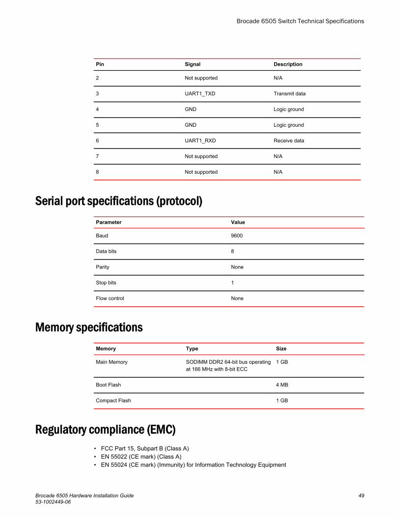
Pin Signal Description
2 Not supported N/A
3 UART1_TXD Transmit data
4 GND Logic ground
5 GND Logic ground
6 UART1_RXD Receive data
7 Not supported N/A
8 Not supported N/A
Serial port specifications (protocol)Parameter Value
Baud 9600
Data bits 8
Parity None
Stop bits 1
Flow control None
Memory specificationsMemory Type Size
Main Memory SODIMM DDR2 64-bit bus operatingat 166 MHz with 8-bit ECC
1 GB
Boot Flash 4 MB
Compact Flash 1 GB
Regulatory compliance (EMC)• FCC Part 15, Subpart B (Class A)• EN 55022 (CE mark) (Class A)• EN 55024 (CE mark) (Immunity) for Information Technology Equipment
Brocade 6505 Switch Technical Specifications
Brocade 6505 Hardware Installation Guide 4953-1002449-06

• ICES-003 (Canada) (Class A)• AS/NZ 55022 (Australia) (Class A)• VCCI (Japan) (Class A)• EN 61000-3-2• EN 61000-3-3• EN 61000-6-1
Regulatory compliance (safety)• CAN/CSA-C22.2 No. 60950-1-07/UL60950-1 - Safety of Information Technology Equipment• EN 60825-1 Safety of Laser Products - Part 1: Equipment Classification, Requirements and User’s
Guide• EN 60825-2 Safety of Laser Products - Part 2: Safety of Optical Fibre Communications Systems• EN 60950-1, IEC 60950-1 Safety of Information Technology Equipment
Regulatory compliance (environmental)• 2011/65/EU - Restriction of the use of certain hazardous substance in electrical and electronic
equipment (EU RoHS)• 2012/19/EU - Waste electrical and electronic equipment (EU WEEE)• 94/62/EC - packaging and packaging waste (EU)• 2006/66/EC - batteries and accumulators and waste batteries and accumulators (EU battery
directive)• 1907/2006 of the European Parliament and of the Council of 18 December 2006 concerning the
Registration, Evaluation, Authorisation and Restriction of Chemicals (EU REACH)• Section 1502 of the Dodd-Frank Wall Street Reform and Consumer Protection Act of 2010 - U.S.
Conflict Minerals• 30/2011/TT-BCT - Vietnam circular• SJ/T 11363-2006 Requirements for Concentration Limits for Certain Hazardous Substances in EIPs
(China)• SJ/T 11364-2006 Marking for the Control of Pollution Caused by EIPs (China)
Brocade 6505 Switch Technical Specifications
50 Brocade 6505 Hardware Installation Guide53-1002449-06

Regulatory Statements
● BSMI statement (Taiwan)................................................................................................51● Canadian requirements...................................................................................................51● CE Statement..................................................................................................................51● China CC statement........................................................................................................52● China ROHS................................................................................................................... 53● FCC warning (US only)................................................................................................... 53● Germany......................................................................................................................... 53● KCC statement (Republic of Korea)................................................................................53● VCCI statement...............................................................................................................53
BSMI statement (Taiwan)
Warning:
This is Class A product. In a domestic environment this product may cause radio interference in whichcase the user may be required to take adequate measures.
Canadian requirementsThis Class A digital apparatus meets all requirements of the Canadian Interference-Causing EquipmentRegulations, ICES-003 Class A.
Cet appareil numérique de la classe A est conforme à la norme NMB-003 du Canada.
CE Statement
ATTENTIONThis is a Class A product. In a domestic environment, this product might cause radio interference, andthe user might be required to take corrective measures.
The standards compliance label on this device contains the CE mark which indicates that this systemconforms to the provisions of the following European Council directives, laws, and standards:
Brocade 6505 Hardware Installation Guide 5153-1002449-06

• Electromagnetic Compatibility (EMC) Directive 2004/108/EEC• Low Voltage Directive (LVD) 2006/95/EC• EN50082-2/EN55024:1998 (European Immunity Requirements)
‐ EN61000-3-2/JEIDA (European and Japanese Harmonics Spec)‐ EN61000-3-3
China CC statement
China CC statement
52 Brocade 6505 Hardware Installation Guide53-1002449-06

China ROHS
Refer to the latest revision of the China ROHS document (P/N 53‐1000428‐xx) which ships with theproduct.
FCC warning (US only)This equipment has been tested and complies with the limits for a Class A computing device pursuantto Part 15 of the FCC Rules. These limits are designed to provide reasonable protection against harmfulinterference when the equipment is operated in a commercial environment.
This equipment generates, uses, and can radiate radio frequency energy, and if not installed and usedin accordance with the instruction manual, might cause harmful interference to radio communications.Operation of this equipment in a residential area is likely to cause harmful interference, in which casethe user will be required to correct the interference at the user’s own expense.
GermanyMachine noise information regulation - 3. GPSGV, the highest sound pressure level value is 70.0 dB(A)in accordance with EN ISO 7779.
Maschinenlärminformations-Verordnung - 3. GPSGV, der höchste Schalldruckpegel beträgt 70.0 dB(A)gemäss EN ISO 7779.
KCC statement (Republic of Korea)
Class A device (Broadcasting Communication Device for Office Use): This device obtained EMCregistration for office use (Class A), and may be used in places other than home. Sellers and/or usersneed to take note of this.
VCCI statement
China ROHS
Brocade 6505 Hardware Installation Guide 5353-1002449-06

This is a Class A product based on the standard of the Voluntary Control Council for Interference byInformation Technology Equipment (VCCI). If this equipment is used in a domestic environment, radiodisturbance might arise. When such trouble occurs, the user might be required to take correctiveactions.
Regulatory Statements
54 Brocade 6505 Hardware Installation Guide53-1002449-06
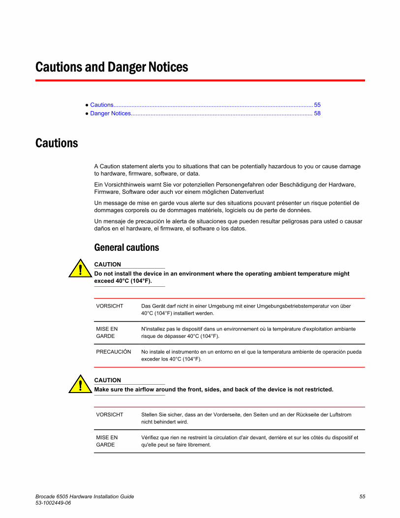
Cautions and Danger Notices
● Cautions.......................................................................................................................... 55● Danger Notices............................................................................................................... 58
Cautions
A Caution statement alerts you to situations that can be potentially hazardous to you or cause damageto hardware, firmware, software, or data.
Ein Vorsichthinweis warnt Sie vor potenziellen Personengefahren oder Beschädigung der Hardware,Firmware, Software oder auch vor einem möglichen Datenverlust
Un message de mise en garde vous alerte sur des situations pouvant présenter un risque potentiel dedommages corporels ou de dommages matériels, logiciels ou de perte de données.
Un mensaje de precaución le alerta de situaciones que pueden resultar peligrosas para usted o causardaños en el hardware, el firmware, el software o los datos.
General cautionsCAUTIONDo not install the device in an environment where the operating ambient temperature mightexceed 40°C (104°F).
VORSICHT Das Gerät darf nicht in einer Umgebung mit einer Umgebungsbetriebstemperatur von über40°C (104°F) installiert werden.
MISE ENGARDE
N'installez pas le dispositif dans un environnement où la température d'exploitation ambianterisque de dépasser 40°C (104°F).
PRECAUCIÓN No instale el instrumento en un entorno en el que la temperatura ambiente de operación puedaexceder los 40°C (104°F).
CAUTIONMake sure the airflow around the front, sides, and back of the device is not restricted.
VORSICHT Stellen Sie sicher, dass an der Vorderseite, den Seiten und an der Rückseite der Luftstromnicht behindert wird.
MISE ENGARDE
Vérifiez que rien ne restreint la circulation d'air devant, derrière et sur les côtés du dispositif etqu'elle peut se faire librement.
Brocade 6505 Hardware Installation Guide 5553-1002449-06

PRECAUCIÓN Asegúrese de que el flujo de aire en las inmediaciones de las partes anterior, laterales yposterior del instrumento no esté restringido.
CAUTIONEnsure that the airflow direction of the power supply unit matches that of the installed fan tray.The power supplies and fan trays are clearly labeled with either a green arrow with an "E", oran orange arrow with an "I."
VORSICHT Vergewissern Sie sich, dass die Luftstromrichtung des Netzteils der eingebauten Lüftereinheitentspricht. Die Netzteile und Lüftereinheiten sind eindeutig mit einem grünen Pfeil und demBuchstaben "E" oder einem orangefarbenen Pfeil mit dem Buchstaben "I" gekennzeichnet.
MISE ENGARDE
Veillez à ce que le sens de circulation de l'air du bloc d'alimentation corresponde à celui dutiroir de ventilation installé. Les blocs d'alimentation et les tiroirs de ventilation sont étiquetésd'une flèche verte avec un "E " ou d'une flèche orange avec un " I ".
PRECAUCIÓN Asegúrese de que la dirección del flujo de aire de la unidad de alimentación se correspondacon la de la bandeja del ventilador instalada. Los dispositivos de alimentación y las bandejasdel ventilador están etiquetadas claramente con una flecha verde y una "E" o con una flechanaranja y una "I".
CAUTIONChanges or modifications made to this device that are not expressly approved by the partyresponsible for compliance could void the user's authority to operate the equipment.
VORSICHT Falls dieses Gerät verändert oder modifiziert wird, ohne die ausdrückliche Genehmigung derfür die Einhaltung der Anforderungen verantwortlichen Partei einzuholen, kann dem Benutzerder weitere Betrieb des Gerätes untersagt werden.
MISE ENGARDE
Les éventuelles modifications apportées à cet équipement sans avoir été expressémentapprouvées par la partie responsable d'en évaluer la conformité sont susceptibles d'annuler ledroit de l'utilisateur à utiliser cet équipement.
PRECAUCIÓN Si se realizan cambios o modificaciones en este dispositivo sin la autorización expresa de laparte responsable del cumplimiento de las normas, la licencia del usuario para operar esteequipo puede quedar anulada.
Electrical cautionsCAUTIONBefore plugging a cable into to any port, be sure to discharge the voltage stored on the cableby touching the electrical contacts to ground surface.
VORSICHT Bevor Sie ein Kabel in einen Anschluss einstecken, entladen Sie jegliche im Kabelvorhandene elektrische Spannung, indem Sie mit den elektrischen Kontakten eine geerdeteOberfläche berühren.
Cautions and Danger Notices
56 Brocade 6505 Hardware Installation Guide53-1002449-06

MISE ENGARDE
Avant de brancher un câble à un port, assurez-vous de décharger la tension du câble enreliant les contacts électriques à la terre.
PRECAUCIÓN Antes de conectar un cable en cualquier puerto, asegúrese de descargar la tensiónacumulada en el cable tocando la superficie de conexión a tierra con los contactos eléctricos.
CAUTIONStatic electricity can damage the chassis and other electronic devices. To avoid damage, keepstatic-sensitive devices in their static-protective packages until you are ready to install them.
VORSICHT Statische Elektrizität kann das System und andere elektronische Geräte beschädigen. UmSchäden zu vermeiden, entnehmen Sie elektrostatisch empfindliche Geräte erst aus derenantistatischer Schutzhülle, wenn Sie bereit für den Einbau sind.
MISE ENGARDE
L'électricité statique peut endommager le châssis et les autres appareils électroniques. Pouréviter tout dommage, conservez les appareils sensibles à l'électricité statique dans leuremballage protecteur tant qu'ils n'ont pas été installés.
PRECAUCIÓN La electricidad estática puede dañar el chasis y otros dispositivos electrónicos. A fin de impedirque se produzcan daños, conserve los dispositivos susceptibles de dañarse con la electricidadestática dentro de los paquetes protectores hasta que esté listo para instalarlos.
CAUTIONIf you do not install a module or a power supply in a slot, you must keep the slot filler panel inplace. If you run the chassis with an uncovered slot, the system will overheat.
VORSICHT Falls kein Modul oder Netzteil im Steckplatz installiert wird, muss die Steckplatztafel angebrachtwerden. Wenn ein Steckplatz nicht abgedeckt wird, läuft das System heiß.
MISE ENGARDE
Si vous n’installez pas de module ou de bloc d'alimentation dans un slot, vous devez laisser lepanneau du slot en place. Si vous faites fonctionner le châssis avec un slot découvert, lesystème surchauffera.
PRECAUCIÓN Si no instala un módulo o un fuente de alimentación en la ranura, deberá mantener el panel deranuras en su lugar. Si pone en funcionamiento el chasis con una ranura descubierta, elsistema sufrirá sobrecalentamiento.
CAUTIONCarefully follow the mechanical guides on each side of the power supply slot and make sure thepower supply is properly inserted in the guides. Never insert the power supply upside down.
VORSICHT Beachten Sie mechanischen Führungen an jeder Seite des Netzteils, das ordnungegemäß indie Führungen gesteckt werden muss. Das Netzteil darf niemals umgedreht eingestecktwerden.
Cautions and Danger Notices
Brocade 6505 Hardware Installation Guide 5753-1002449-06

MISE ENGARDE
Suivez attentivement les repères mécaniques de chaque côté du slot du bloc d'alimentation etassurez-vous que le bloc d'alimentation est bien inséré dans les repères. N'insérez jamais lebloc d'alimentation à l'envers.
PRECAUCIÓN Siga cuidadosamente las guías mecánicas de cada lado de la ranura del suministro de energíay verifique que el suministro de energía está insertado correctamente en las guías. No insertenunca el suministro de energía de manera invertida.
CAUTIONThe power supply switch must be in the off position when you insert the power supply into thechassis. Damage to the switch can result if a live power supply is installed.
VORSICHT Der Schalter des Netzteils muss in der Stellung „Aus“ stehen, wenn das Netzteil in dasGehäuse eingesetzt wird. Wenn ein spannungsführendes Netzteil (Schalterstellung "Ein")eingebaut wird, kann dies zu Beschädigungen am Switch führen.
MISE ENGARDE
Le commutateur d'alimentation doit être en position d'arrêt lorsque vous insérez la sourced'alimentation dans le châssis. Si une source d'alimentation sous tension est installée, desdommages peuvent être causés.
PRECAUCIÓN El interruptor de la fuente de alimentación debe estar en la posición de apagado en elmomento de introducirla en el chasis. El conmutador puede resultar dañado si se instala unafuente de alimentación activa.
Danger Notices
A Danger statement indicates conditions or situations that can be potentially lethal or extremelyhazardous to you. Safety labels are also attached directly to products to warn of these conditions orsituations.
Ein Gefahrenhinweis warnt vor Bedingungen oder Situationen die tödlich sein können oder Sie extremgefährden können. Sicherheitsetiketten sind direkt auf den jeweiligen Produkten angebracht um vordiesen Bedingungen und Situationen zu warnen.
Un paragraphe Danger indique des conditions ou des situations potentiellement mortelles ouextrêmement dangereuses. Des labels de sécurité sont posés directement sur le produit et vousavertissent de ces conditions ou situations
Una advertencia de peligro indica condiciones o situaciones que pueden resultar potencialmenteletales o extremadamente peligrosas. También habrá etiquetas de seguridad pegadas directamentesobre los productos para advertir de estas condiciones o situaciones.
Electrical dangersDANGERFor safety reasons, the ESD wrist strap should contain a series 1 megaohm resistor.
Danger Notices
58 Brocade 6505 Hardware Installation Guide53-1002449-06

GEFAHR Aus Sicherheitsgründen sollte ein EGB-Armband zum Schutz von elektronischen gefährdetenBauelementen mit einem 1 Megaohm-Reihenwiderstand ausgestattet sein.
DANGER Pour des raisons de sécurité, la dragonne ESD doit contenir une résistance de série 1 mégaohm.
PELIGRO Por razones de seguridad, la correa de muñeca ESD deberá contener un resistor en serie de 1mega ohmio.
DANGERMake sure that the power source circuits are properly grounded, then use the power cordsupplied with the device to connect it to the power source.
GEFAHR Stellen Sie sicher, dass die Stromkreise ordnungsgemäß geerdet sind. Benutzen Sie dann dasmit dem Gerät gelieferte Stromkabel, um es an die Srromquelle anzuschließen.
DANGER Vérifiez que les circuits de sources d'alimentation sont bien mis à la terre, puis utilisez lecordond'alimentation fourni avec le dispositif pour le connecter à la source d'alimentation.
PELIGRO Verifique que circuitos de la fuente de corriente están conectados a tierra correctamente; luegouse el cordón de potencia suministrado con el instrumento para conectarlo a la fuente decorriente
DANGERRemove both power cords before servicing.
GEFAHR Trennen Sie beide Netzkabel, bevor Sie Wartungsarbeiten durchführen.
DANGER Retirez les deux cordons d'alimentation avant toute maintenance.
PELIGRO Desconecte ambos cables de alimentación antes de realizar reparaciones.
DANGERDisconnect the power cord from all power sources to completely remove power from the device.
GEFAHR Ziehen Sie das Stromkabel aus allen Stromquellen, um sicherzustellen, dass dem Gerät keinStrom zugeführt wird.
DANGER Débranchez le cordon d'alimentation de toutes les sources d'alimentation pour coupercomplètement l'alimentation du dispositif.
PELIGRO Para desconectar completamente la corriente del instrumento, desconecte el cordón decorriente de todas las fuentes de corriente.
Cautions and Danger Notices
Brocade 6505 Hardware Installation Guide 5953-1002449-06

DANGERTo avoid high voltage shock, do not open the device while the power is on.
GEFAHR Das eingeschaltete Gerät darf nicht geöffnet werden, da andernfalls das Risiko einesStromschlags mit Hochspannung besteht.
DANGER Afin d'éviter tout choc électrique, n'ouvrez pas l'appareil lorsqu'il est sous tension.
PELIGRO Para evitar una descarga de alto voltaje, no abra el dispositivo mientras esté encendido.
DANGERRisk of explosion if battery is replaced by an incorrect type. Dispose of used batteriesaccording to the instructions.
GEFAHR Es besteht Explosionsgefahr, wenn ein unzulässiger Batterietyp eingesetzt wird.
Verbrauchte Batterien sind entsprechend den geltenden Vorschriften zu entsorgen.
DANGER Risque d'explosion en cas de remplacement de la pile par un modèle incorrect.
Débarrassez-vous des piles usagées conformément aux instructions.
PELIGRO Riesgo de explosión si se sustituye la batería por una de tipo incorrecto.
Deshágase de las baterías usadas de acuerdo con las instrucciones.
Dangers related to equipment weightDANGERMake sure the rack housing the device is adequately secured to prevent it from becomingunstable or falling over.
GEFAHR Stellen Sie sicher, dass das Gestell für die Unterbringung des Geräts auf angemessene Weisegesichert ist, so dass das Gestell oder der Schrank nicht wackeln oder umfallen kann.
DANGER Vérifiez que le bâti abritant le dispositif est bien fixé afin qu'il ne devienne pas instable ou qu'ilne risque pas de tomber.
PELIGRO Verifique que el bastidor que alberga el instrumento está asegurado correctamente para evitarque pueda hacerse inestable o que caiga.
Cautions and Danger Notices
60 Brocade 6505 Hardware Installation Guide53-1002449-06