Embed Size (px)
Citation preview


1
Compact wall mounted and free standing pressurisation units, utilising the latest microprocessor control. For use on sealed heating and cooling systems, offering accurate control and reliability.
♦ Digital equipment comes with a 4 digit bright LED display with scrolling messages including pump operation and alarm modes.
♦ Single or twin pump configurations.♦ Complete with integral water break tank utilising an AB airgap and a WRAS approved float valve.♦ Twin pump equipment operates as cyclic duty – standby with automatic changeover.♦ Internal alarm with mute function.♦ Security password protected.♦ Auto resetting low water detection, for pump protection.♦ Auto resetting high and low pressure alarm.♦ Digital pressure setpoint with adjustable differential.♦ Flood protection through a pump run limit timer.♦ Normally closed, common fault, volt free contact (Boiler interlock).♦ Normally open, individual volt free contacts for pump trip, high pressure, low pressure and sensor health.♦ All volt free contacts are rated for use with electrical supplies up to 230v with a maximum current draw of 5 amps.
♦ RS 485 Connectivity
♦ Hours run counter(per pump)
♦ 12 month service reminder
♦ Excessive start alarm (>3 times in 8 hours)
♦ Pump pulse option
(2 second pulse per pump
if inactive for 60 days)
♦ Fill system option(Not available on 13OD/23OD)
Broag P ressur i sa t i on equ ipment

2
Broag P ressur i sa t i on equ ipment

3

4
Remtank Unvented Cyl inders Expansion Vessel suppl ied with k i ts
Maximum e
Using
Water at 10 C expands approx. 0.5%Water at 60 C expands approx. 1.7%
Using a safety factor of 25% water expands between 10 C and 60 C @ 1.5%Using the vessel efficiency calculated as above = 42.8%1000 Ltr x 1.5% = 15 Ltr expansion; 15 / 42.8% = 35 (35 Ltr vessel)800 Ltr x 1.5% = 12 Ltr expansion; 12 / 42.8% = 28 (35 Ltr vessel)500 Ltr x 1.5% = 7.5 Ltr expansion; 7.5 / 42.8% = 17.5 (24 Ltr vessel)
(NOTE: The above sizing relates to Cylinder water content ONLY. Any additional system expansion should be calculated independently.)
o
o
o o

5
6
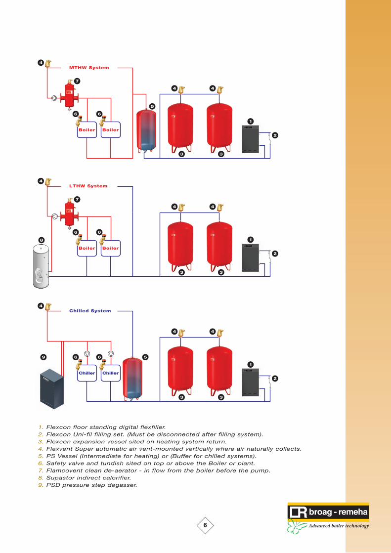
1. Flexcon floor standing digital flexfiller.2. Flexcon Uni-fil filling set. (Must be disconnected after filling system).3. Flexcon expansion vessel sited on heating system return.4. Flexvent Super automatic air vent-mounted vertically where air naturally collects.5. PS Vessel (Intermediate for heating) or (Buffer for chilled systems).6. Safety valve and tundish sited on top or above the Boiler or plant.7. Flamcovent clean de-aerator - in flow from the boiler before the pump.8. Supastor indirect calorifier.9. PSD pressure step degasser.

7
R e m t a n k S S D i re c t u n v e n t e d c y l i n d e r s
Select ion Guide
*In areas with a high concentration of
Chlorine (200 ppm or above) additional
protection of the cylinder is required
with an electronic anode.
This is an optional extra and is not
reflected in the pricing.
Property Type Direct SizeBedsit
1/2 beds with 1 bath / shower
3 beds with 1 bath / shower
4 beds with 1 bath / shower
2/3 beds with 2 baths / showers
4/5 beds with 2 baths / showers
Sports club, Restaurant etc.
Hotels, Schools etc
120
150 or 180
180 or 210
210
210 or 250
300 or 500
800 or 1000
Technical Speci f icat ion Direct ( including Ki t )
Volume (Nominal)
1750
606
42
342
3/4”
7 bar
95ºC
6 bar
2
3 kW
101 mins
144 mins
35 Ltr
977
555
20.8
141
3/4”
7 bar
95ºC
6 bar
2
3 kW
34 mins
40 mins
35 Ltr
1167
555
23.5
174
3/4”
7 bar
95ºC
6 bar
2
3 kW
46 mins
65 mins
35 Ltr
1347
555
26.5
207
3/4”
7 bar
95ºC
6 bar
2
3 kW
56 mins
80 mins
35 Ltr
1569
555
33
243
3/4”
7 bar
95ºC
6 bar
2
3 kW
69 mins
98 mins
35 Ltr
1759
555
35.5
286
3/4”
7 bar
95ºC
6 bar
2
3 kW
80 mins
114 mins
35 Ltr
1823
734
59
559
3/4”
7 bar
95ºC
6 bar
2
3 kW
159 mins
256 mins
50 Ltr
Direct Height (mm)
Diameter (mm)
Weight (Dry kg)
Weight (Normal Full kg)
T&P Tapping
T&P Pressure Setting
T&P Temperature Setting
Expansion Relief Setting
Electrical Heater Quantity
Electrical Heater Rating (Each)
Re-heat Times (2x3 kW)
Heat Up Times (From Cold)
Expansion Vessel
120 litres 150 litres 180 litres 210 litres 250 litres 300 litres 500 litres
Direct unvented cylinders for potable water installations
Fluid Flow SequenceMains Water Isolation Valve (Not Supplied)
3 bar Pressure Reducing Valve
Safety Group (6 bar Expansion Relief Valve c/w Non Return Valve)
Expansion Vessel
Drain Valve (Not Supplied)
Stainless Supastor Hot Water Calorifier
Pressure Reducing
Valve Pre-SetSafety Group c/w
Non Return Valve
6 bar Relief
Tundish Combined Temperature
& Pressure Relief Valve
Factory Fitted
7 bar / 95oC
Expansion Vessel
120 - 500 3/4” Connection
800 - 1000 1” (Floor Standing Model)
2 off 3kW 230v/50Hz
Immersion Heater
VesselsDirect vessels
can be supplied
without kits as
a storage vessel
800 litres 1000 litres
1960
950
100
900
3/4”
7 bar
95ºC
6 bar
2
3 kW
260 mins
400 mins
80 Ltr
2360
950
115
1115
3/4”
7 bar
95ºC
6 bar
2
3 kW
318 mins
512 mins
80 Ltr
Insulation is interlocked polystyrene to allow for inspection of cylinder if required.
N.B. The expansion vessel provided is sized to accommodate a total hot water system volume of 1.25 times the calorifier size. It is theresponsibility of the installer to verify that this vessel size is appropriate for the installation and add additional vessels if required.

8
R e m t a n k S S D i re c t u n v e n t e d c y l i n d e r s
120 to 300 litre 500 to 1000 litre
1750
606
47
1” BSP (M)
282
1532
1444
Top Centre
1” BSP (M)
977
555
51
1” BSP (M)
289
749
644
Top Centre
1” BSP (M)
1167
555
51
1” BSP (M)
289
939
834
Top Centre
1” BSP (M)
1347
555
51
1” BSP (M)
289
1119
1014
Top Centre
1” BSP (M)
1569
555
51
1” BSP (M)
289
1341
1236
Top Centre
1” BSP (M)
1759
555
51
1” BSP (M)
289
1531
1426
Top Centre
1” BSP (M)
1823
734
52
1” BSP (M)
317
1517
932
1517
1” BSP (M)
Height A (mm)
Diameter B (mm)
Cold Water C (mm)
Cold Water Connection
Immersion D (mm)
T&P Valve J (mm)
Immersion K (mm)
DHW Flow J
DHW Connection
120 litres 150 litres 180 litres 210 litres 250 litres 300 litres 500 litresDirect Direct Direct Direct Direct Direct Direct
Volume (Nominal)
Technical Speci f icat ion Connect ions800 litres 1000 litres
Direct Direct
1960
950
338
1 1/2”BSP (M)
343
1603
1103
1603
1 1/2”BSP (M)
2360
950
338
1 1/2”BSP (M)
343
2003
1103
2003
1 1/2”BSP (M)
Secondary Flow
(120 - 300)
(500 - 1000)

9
R e m t a n k S S I n d i re c t u n v e n t e d c y l i n d e r s
Select ion Guide
*In areas with a high concentration of
Chlorine (200 ppm or above) additional
protection of the cylinder is required
with an electronic anode.
This is an optional extra and is not
reflected in the pricing.
Property Type Indirect SizeBedsit
1/2 beds with 1 bath / shower
3 beds with 1 bath / shower
4 beds with 1 bath / shower
2/3 beds with 2 baths / showers
4/5 beds with 2 baths / showers
Sports club, Restaurant etc.
Hotels, Schools etc
120
150 or 180
180 or 210
210
210 or 250
300 or 500
800 or 1000
Indirect unvented cylinders for potable water installations
Fluid Flow SequenceMains Water Isolation Valve (Not Supplied)
3 bar Pressure Reducing Valve
Safety Group (6 bar Expansion Relief Valve c/w Non Return Valve)
Expansion Vessel
Drain Valve (Not Supplied)
Stainless Supastor Hot Water Calorifier
Pressure Reducing
Valve Pre-SetSafety Group c/w
Non Return Valve
6 bar Relief
Tundish
2 Port Valve For Use
With The IMIT
Thermostat
Controlling The
Primary Flow (Boiler)
Water To The Coil
Combined Temperature &
Pressure Relief Valve
7 bar / 95oC
3kW 230v/50Hz
Immersion Heater
IMIT Combined
Thermostat &
Safety Relay
Technical Speci f icat ion Indirect ( including Ki t )
Volume (Nominal) 120 litres 150 litres 180 litres 210 litres 250 litres 300 litres 500 litres 800 litres 1000 litres
Indirect Height (mm)
Diameter (mm)
Weight (Dry kg)
Weight (Normal Full kg)
T&P Tapping
T&P Pressure Setting
T&P Temperature Setting
Expansion Relief Setting
Electrical Heater Quantity
Electrical Heater Rating (Each)
Re-heat Times (82º Supply)
Heat Up Times (From Cold)
Max. Primary Pressure (Coil)
Primary Flow Rate (Boiler L/min)
Primary Resistance (mbar)
976
555
23
143
3/4”
7 bar
95ºC
6 bar
1
3 kW
17 mins
29 mins
16 bar
25
64.9
464
24.7
35 Ltr
1167
555
27
177
3/4”
7 bar
95ºC
6 bar
1
3 kW
20 mins
31 mins
16 bar
34
141.9
493
26.2
35 Ltr
1347
555
30
210
3/4”
7 bar
95ºC
6 bar
1
3 kW
25 mins
37 mins
16 bar
34
141.930
493
26.2
35 Ltr
1569
555
38
248
3/4”
7 bar
95ºC
6 bar
1
3 kW
22 mins
27 mins
16 bar
42
324.8
627
33.4
35 Ltr
1759
555
41
291
3/4”
7 bar
95ºC
6 bar
1
3 kW
24 mins
30 mins
16 bar
42
354.6
684
36.4
35 Ltr
1960
950
110.5
911
3/4”
7 bar
95ºC
6 bar
2
3 kW
31 mins
40 mins
16 bar
92
1287.0
1695
90.2
80 Ltr
2360
950
124.5
1245
3/4”
7 bar
95ºC
6 bar
2
3 kW
40 mins
49 mins
16 bar
92
1287.0
1695
90.2
80 Ltr
Continuous Output (mbar)
Coil Rating kW
Expansion Vessel
1750
606
50
350
3/4”
7 bar
95ºC
6 bar
1
3 kW
28 mins
35 mins
16 bar
42
520
985
52.4
35 Ltr
1823
734
68.5
569
3/4”
7 bar
95ºC
6 bar
1
3 kW
31 mins
38 mins
16 bar
67
509.8
1059
56.4
50 Ltr
Insulation is interlocked polystyrene to allow for inspection of cylinder if required.
Expansion Vessel
120 - 500 3/4” Connection
800 - 1000 1” (Floor Standing Model)
N.B. The expansion vessel provided is sized to accommodate a total hot water system volume of 1.25 times the calorifier size. It is theresponsibility of the installer to verify that this vessel size is appropriate for the installation and add additional vessels if required.

10
R e m t a n k S S I n d i re c t u n v e n t e d c y l i n d e r s
1750
606
47
1” BSP (M)
412
47
722
1”BSP (M)
802
1” BSP (F)
1225
1532
N/A
Top Centre
1”BSP (M)
976
555
51
1” BSP (M)
419
51
379
1” BSP (M)
518
1” BSP (F)
627
749
N/A
Top Centre
1”BSP (M)
1167
555
51
1” BSP (M)
419
51
379
1”BSP (M)
518
1” BSP (F)
721
939
N/A
Top Centre
1”BSP (M)
1347
555
51
1” BSP (M)
419
51
379
1”BSP (M)
518
1” BSP (F)
845
1119
N/A
Top Centre
1”BSP (M)
1569
555
51
1” BSP (M)
419
51
554
1”BSP (M)
634
1” BSP (F)
984
1341
N/A
Top Centre
1”BSP (M)
1759
555
51
1” BSP (M)
419
51
579
1”BSP (M)
659
1” BSP (F)
1108
1531
N/A
Top Centre
1”BSP (M)
1823
734
52
1” BSP (M)
932
312
832
1”BSP (M)
1142
1” BSP (F)
952
1517
N/A
1517
1”BSP (M)
Height A (mm)
Diameter B (mm)
Cold Water C (mm)
Cold Water Connection
Immersion D (mm)
Primary Flow F (mm)
Primary Return E (mm)
Primary Connection
DHW Return G (mm)
Secondary Return Connection (mm)
Thermostat H (mm)
T&P Valve J (mm)
Immersion K (mm)
DHW Flow J
DHW Connection
120 litres Indirect
150 litres Indirect
180 litres Indirect
210 litresIndirect
250 litres Indirect
300 litres Indirect
500 litres Indirect
800 litres Indirect
1000 litres Indirect
1960
950
50
1.1/2”BSP (M)
343
338
1038
1”BSP (M)
1238
1.1/2” BSP (F)
1103
1603
1103
1603
1.1/2”BSP (M)
2360
950
338
1.1/2”BSP (M)
343
338
1038
1”BSP (M)
1238
1.1/2” BSP (F)
1103
2023
1103
2003
1.1/2”BSP (M)
Volume (Nominal)
Technical Speci f icat ion Connect ions
120 to 300 litre 800 to 1000 litre500 litre
Secondary Flow
(120 - 300)
(500 - 1000)
Indirect unvented cylinders for potable water installations

11
Pressure Reducing
Valve Pre-SetTundish
2 Port Valve For Use With
The IMIT Thermostat
Controlling The Primary Flow
(Boiler) Water To The Coil
Combined Temperature &
Pressure Relief Valve
Factory Fitted 7 bar / 95oC
3kW 230v/50Hz
Immersion Heater
IMIT Combined
Thermostat &
Safety Relay
R e m t a n k S S S o l a r u n v e n t e d c y l i n d e r s
Technical Speci f icat ion SS Solar ( including Ki t )
Volume (Nominal) 250 litres 300 litres 500 litres 800 litres 1000 litres
Supastor Solar Height (mm)
Diameter (mm)
Weight (Dry kg)
Weight (Normal Full kg)
T&P Tapping
T&P Pressure Setting
T&P Temperature Setting
Expansion Relief Setting
Electrical Heater Quantity
Electrical Heater Rating (Each)
Primary Re-heat Times (82º Supply)
Primary Heat Up Times (From Cold)
Max. Primary Pressure (Coil)
Primary Flow Rate (Boiler L/M)
Primary Resistance (mbar)
1568
555
43
253
3/4”
7 bar
95ºC
6 bar
1
3 kW
22 mins
27 mins
16 bar
42
324.8
627
33.4
1750
606
55
355
3/4”
7 bar
95ºC
6 bar
1
3 kW
28 mins
35 mins
16 bar
42
520
985
52.4
1823
734
75.5
576
3/4”
7 bar
95ºC
6 bar
1
3 kW
31 mins
38 mins
16 bar
67
509.8
1059
56.4
1960
950
122.9
923.4
3/4”
7 bar
95ºC
6 bar
2
3 kW
31 mins
40 mins
16 bar
92
1287.0
1695
90.2
2360
950
136.9
1257.4
3/4”
7 bar
95ºC
6 bar
2
3 kW
40 mins
49 mins
16 bar
92
1287.0
1641
87.4Primary Coil Rating KW
Expansion Vessel
Primary Continuous Output (mbar)
210 litres
1754
555
46
296
3/4”
7 bar
95ºC
6 bar
1
3 kW
24 mins
30 mins
16 bar
42
354.6
684
36.4
Select ion Guide
*In areas with a high concentration of
Chlorine (200 ppm or above) additional
protection of the cylinder is required
with an electronic anode.
This is an optional extra and is not
reflected in the pricing.
Property Type Solar SizeBedsit
1/2 beds with 1 bath / shower
3 beds with 1 bath / shower
4 beds with 1 bath / shower
2/3 beds with 2 baths / showers
4/5 beds with 2 baths / showers
Sports club, Restaurant etc.
Hotels, Schools etc
120
150 or 180
180 or 210
210
210 or 250
300 or 500
800 or 1000
35 Ltr 35 Ltr 35 Ltr 50 Ltr 80 Ltr 80 Ltr
Insulation is interlocked polystyrene to allow for inspection of cylinder if required.
Fluid Flow SequenceMains Water Isolation Valve (Not Supplied)
3 bar Pressure Reducing Valve
Safety Group (6 bar Expansion Relief Valve c/w Non Return Valve)
Expansion Vessel
Drain Valve (Not Supplied)
Stainless Supastor Hot Water Calorifier
Expansion Vessel
120 - 500 3/4” Connection
800 - 1000 1” (Floor Standing Model)
Solar unvented cylinders for potable water installations
Safety Group c/w
Non Return Valve
6 bar Relief
N.B. The expansion vessel provided is sized to accommodate a total hot water system volume of 1.25 times the calorifier size. It is theresponsibility of the installer to verify that this vessel size is appropriate for the installation and add additional vessels if required.

12
R e m t a n k S S S o l a r u n v e n t e d c y l i n d e r s
Technical Speci f icat ion Connect ions
2360
950
338
1.1/2”BSP (M)
343
338
1038
1” BSP (M)
1238
1” BSP (F)
1103
2023
1103
2003
1.1/2”BSP (M)
1443
1853
1”BSP (M)
1103
1568
555
51
1” BSP (M)
881
51
379
1” BSP (M)
634
1” BSP (F)
1216
1341
N/A
Top Centre
1” BSP (M)
1098
1341
1”BSP (M)
289
1754
555
51
1” BSP (M)
834
51
379
1” BSP (M)
659
1” BSP (F)
1108
1531
N/A
Top Centre
1” BSP (M)
1288
1531
1”BSP (M)
289
1750
606
47
1” BSP (M)
1117
47
372
1” BSP (M)
774
1” BSP (F)
1225
1532
N/A
Top Centre
1” BSP (M)
1017
774
1”BSP (M)
282
1823
734
52
1” BSP (M)
932
312
832
1” BSP (M)
952
1” BSP (F)
952
1517
N/A
1517
1” BSP (M)
1077
1437
1”BSP (M)
558
1960
950
338
1.1/2”BSP (M)
343
338
1038
1” BSP (M)
1238
1” BSP (F)
1103
1603
1103
1603
1.1/2”BSP (M)
1193
1603
1”BSP (M)
1103
210 litresSolar
Height A (mm)
Diameter B (mm)
Cold Water C (mm)
Cold Water Connection
Immersion D (mm)
Primary Flow F (mm)
Primary Return E (mm)
Primary Connection
DHW Return G (mm)
DHW Return Connection (mm)
Thermostat H (mm)
T&P Valve J (mm)
Immersion K (mm)
DHW Flow J (mm)
DHW Connection
Solar Return L (mm)
Solar Flow J (mm)
Secondary Connection
Thermostat Primary Coil Pocket (mm)
250 litresSolar
300 litresSolar
500 litresSolar
800 litresSolar
1000 litresSolar
Volume (Nominal)
120 to 300 litre 500 litre 800 to 1000 litre
Secondary Flow
(120 - 300)
(500 - 1000)
Solar unvented cylinders for potable water installations

13
Wi r i n g d e t a i l s f o r a l l D i g i t a l P re s s u r i s a t i o n U n i t s
♦ Supply Voltage 230- v- Single Phase. ♦ Fuse Rating - 5 Amps ♦ Max Full Load Current - 4.5 Amps
• Under normal operation there is a permanent live feed back to the boiler, the water temperature is regulated by the operation of the motorised valve feeding the internal coil.
• To control the heating times, connect the electrical feed to the thermostat from the program or time clock (L).• When the Remtank Calorifier is at the desired temperature, the motorised valve will close and the boiler, itself, will register no demand
from the cylinder and shut down if appropriate.• Note: Control of hot water via Rematic 2945ck and Broag Priority Kits.• When using the Rematic 2945ck controller and Broag Priority Kits in conjunction with the supplied HWS immersion sensor, fit the
supplied brass pocket in the secondary return connection and connect immersion sensor into pocket, the secondary return connection should then be connected into the cold feed supply at the base of the calorifier between the safety group and the calorifier. Sensor wiring connections can be found in the boiler control wiring details.
• The 2 port valve must be wired as detailed in the diagrams above, with the electrical supply coming from the Priority Kit/Boiler controls.To ensure the correct operation of the Priority Kit set the control thermostat (connected to the 2 port valve) 10oC higher than the boiler or controller hot water temperature.

14
A s s e m b l y f o r D i re c t , I n d i re c t a n d S o l a r
1
1
2
2
3
3
4
4
5
5
6
6
A A
B B
C C
D D
Appendix 4
Stainless Supastor Direct Assembly
RJAC MC RJAC 25/05/2006 02/02/2006
Designed by Checked by Approved by Date
1 / 1 Edition Sheet
Date
400mm Maximum Length
400m
mM
inim
umLe
ngth
150mm Minimum Length
200mm Minimum Length
T&P TundishDrain Valve
(Not Supplied)
To Drain To Drain
Pressure Reducing ValveCold Water Inlet
Safety Group
Secondary Return(Anode Connection)
Hot Water Outlet
NOTE: The location of the Pressure Reducing Valve, Expansion Vessel, Safety Group and Drain Valve is flexible, as long as the distances shown and written instructions are followed.
This clause allows the Expasnion Vessel to be located above the Hot Water Calorifer / Cylinder.
1
1
2
2
3
3
4
4
5
5
6
6
A A
B B
C C
D D
Appendix 3
Stainless SupastorIndirect and Solar Assembly
RJAC MC RJAC 25/05/2006 02/02/2006
Designed by Checked by Approved by Date
1 / 1 Edition Sheet
Date
400mm Maximum Length
400m
mM
inim
umLe
ngth
150mmMinimum Length
Hot Water Outlet
Pressure Reducing ValveCold Water Inlet
T&P Tundish
200mm Minimum Length
Drain Valve(Not Supplied)
To Drain
To DrainSafety Group
Primary Return (Boiler)
Primary Flow (Boiler)
Secondary Return(Anode Connection)
NOTE: The location of the Pressure Reducing Valve, Expansion Vessel, Safety Group and Drain Valve is flexible, as long as the distances shown and written instructions are followed.
This clause allows the Expasnion Vessel to be located above the Hot Water Calorifer / Cylinder.

Issue 1 date: 30 10 20082Ed/6262/xx/xxxxIssue 1 date: 30 10 20082Ed/6262/xx/xxxx